installation & maintenance - jh process process equipment - ansima… · installation &...
TRANSCRIPT
Sundyne Corporation is ISO 9001-2000 compliant is certified by Lloyd’s Register Quality Assurance Limited
INSTALLATION & MAINTENANCE (With Priming & Suction Lift Data) KPMODEL KP326/KPi50160/KPj50160 Issued July, 2007
T. S. U. Liquid poured into the casing for initial priming
must be compatible to the incoming liquid. Incompatibility may cause a severe accident.
“Simple by Design”
JH Process Equipment Inc. | 617 Jeffers Circle, Exton, PA 19341 | 610-903-0900 | www.jhprocess.com

2
TABLE OF CONTENTS
1 LIMITED WARRANTY 4
2 PUMP IDENTIFICATION 8
3 SAFETY CHECK LIST 9
4 PRINCIPLE OF MAGNETIC DRIVE PUMPS 11
5 HOW THE KP SELF-PRIMING PUMP WORKS 12
6 PIPING AND INSTALLATION 13 6-a Sump Application 13 6-b Tank Car Unloading 14 6-c Foundation 6-d Installation and Electrical Connections 6-e Earthing Arrangement
16 16 17
7 PUMP START UP AND SHUTDOWN 18 7-a Pre-Start Check List 7-b Start Up and Operation 7-c Shutdown Procedure
18 18 19
8 DISASSEMBLY AND MAINTENANCE 19 8-a Basic Disassembly for Inspection 19 8-b Inspection Checklist 20 8-c Detailed Wear Parts Tolerances 22 8-d Parts Replacement Procedures 23
9 ASSEMBLY 25 9-a Wet End Assembly 25 9-b Mounting the Outer Drive Magnet to the Motor Shaft
or Bearing Frame Shaft 28
9-c Mounting the Motor Risers and Foot 30 9-d Mounting the Wet End With the Bracket/Motor 30 9-e Aligning Pump Mounting Feet 30
10 TRIMMING THE IMPELLER 31

3
TABLE OF CONTENTS 11 BEARING FRAME DISASSEMBLY AND MAINTENANCE 34 11-a Disassembly 34 11-b Inspection and Maintenance of Bearing Frame 37 11-c Assembly of the Bearing Frame 37 12 DRAWINGS 40 13 PART LIST 41 13-a Parts List 1 – Wet End Parts 41 13-b Parts List 2 – Drive End Parts-ANSI Pumps With
NEMA Motors 45
13-c Parts List 3 – Drive End Parts-ANSI Pumps With IEC Motors
47
13-d Bearing Frame Parts List 49 14 PREVENTIVE MAINTENANCE AND PERIODIC CHECK UP 50 15 KP ENGINEERING DATA 51 15-a Priming Time Graphs 51 15-b How to Estimate Priming Time and Temperature
Rise 52
15-c Temperature Rise Graph Using a Thermowell 54
15-d NPSH 55 15-e Common Chemical Properties 59 15-f Unit Conversions 60 16 SHIPPING WEIGHTS 61 16-a Pump Weight 61 16-b Motor Weight 61 17 18
SPECIFICATIONS Addendum 1 – Inactive Parts
61 61
CAUTION Read all instructions before removing pump from shipping container or preparing it for operation. It is important to install and operate the pump correctly to eliminate any possible mishap that may be detrimental to property or personnel. Keep this manual for future reference.

4
Two year limited warranty Ansimag pumps are warranted by Ansimag to the original user against defects in workmanship and materials under normal use for two years after the date of purchase. Any part returned to an Ansimag- designated, authorized service location, shipping cost prepaid, will be evaluated for defects. Parts determined by Ansimag to be defective in material or workmanship will be repaired or replaced at Ansimag's option as the exclusive remedy. Limitation of liability To the extent allowable under applicable law, Ansimag's liability for consequential damages is expressly disclaimed. Ansimag's liability in all events is limited to and shall not exceed the purchase price paid. Warranty disclaimer Ansimag has made a diligent effort to illustrate and describe the products in this literature accurately; however, such illustrations and descriptions are for the sole purpose of identification and do not express or imply a warranty that the products are merchantable, or fit for a particular purpose, or that the products will necessarily conform to the illustration or descriptions. Except as provided below, no warranty or affirmation of fact, expressed or implied, other than as stated in "LIMITED WARRANTY" is made or authorized by Ansimag. Product suitability Many states and localities have codes and regulations governing the sale, construction, installation and/or use of products for certain purposes, which may vary from those in neighboring areas. While Ansimag attempts to assure that its products comply with such codes, it cannot guarantee compliance, and cannot be responsible for how the product is installed or used. Before purchasing and using a product, please review the product application as well as the national and local codes and regulations, and be sure that product, installation, and use complies with them. Warranty exclusions Wear items that must be replaced on a regular basis are not covered under this warranty. Such items include, but are not limited to mouth rings, thrust rings, O-rings, bushings and shafts. Items that have been subject to extreme heat or have been used with abrasive or incompatible chemicals are not covered under this warranty.
1. Limited Warranty

5
EC Declaration of Conformity Manufacturer: Sundyne Corporation
Details of Equipment:
Model Prefix
Alternative Model Description
Description Harmonised Standards applied in order to verify compliance to the Directive
KF KF K K
KM KM KV KV KP KP
ALA (PR, PS, QS, QT Couplings) ALI (PR, PS, QS, QT Couplings)
ALA (A, B,C Couplings) ALI (A, B, C Couplings) ALA (AA, AB Couplings) ALI (AA, AB Couplings)
VALA VALI
SPALA SPALI
Magnetic Drive Sealless
Centrifugal Pumps
MACHINERY DIRECTIVE 98/37/EEC: EN 292-1 Safety of Machinery - Basic Concepts, general principles of design. EN 292-2/A1 Technical principles and specifications (and amendment 1). EN 809 Pumps and pump units for liquids - Common Safety Requirements. ATEX DIRECTIVE 94/9/EC: EN 13463-1 Non-Electrical equipment for potentially explosive atmospheres. Part 1: Basic method and requirements. EN 13463-5 Non-electrical equipment Part 5: Protection by constructional safety ‘c’.
Directives to which the above equipment complies to:
Machinery Directive Directive relating to Machinery (98/37/EC)
ATEX Directive Directive on equipment and protective systems intended for use in potentially explosive atmospheres (94/9/EC)
Group II Categories 2 and 3 (gas)
Notified body: Intertek Testing and Certification Ltd Intertek House Cleeve Road, Leatherhead, Surrey, KT22 7SB UK
Certification Numbers: ITS03ATEX11180
ATEX Technical Construction File Number:
ATEX-ANSIMAG-001
Year in Which CE Mark was affixed: 1996 We certify that Plastic Lined magnetically driven bareshaft, close-coupled, and separately mounted pumps manufactured by the Sundyne Corporation meet the requirements of the above Directives, when installed, operated and maintained in accordance with our published Installation and Operating Manual. Plastic Lined magnetic drive pumps must not be put into service until all the conditions relating to safety noted in these documents have been met. Authorised Signatories on behalf of Sundyne Corporation:
Name: Jeff Wiemelt Position: Vice President and General Manager of Sundyne Corporation, The Americas
Name: Kerry Kramlich
Position: Pump Engineering Manager
Date of issue: 16th June 2003 Place of Issue: United Kingdom

6
SAFETY WARNING
Genuine parts and accessories have been specifically designed and tested for use with these products to ensure continued product quality and performance. Testing cannot be performed on all parts nor on accessories sourced from other vendors, incorrect design and/or fabrication of such parts and accessories may adversely affect the performance and safety features of these products. Failure to properly select, install or use authorised Sundyne parts and accessories is considered misuse, and damage or failure caused by misuse is not covered by Sundyne’s warranty. Additionally, modification of Sundyne products or removal of original components may impair the safety of these products and their effective operation.
EUROPEAN UNION MACHINERY DIRECTIVE (CE mark system)
This document incorporates information relevant to the Machinery Directive 98/37/EC. It should be read prior to the use of any of our equipment. Individual maintenance manuals which also conform to the EU Directive should be read when dealing with specific models.
EUROPEAN UNION ATEX DIRECTIVE
This document incorporates information relevant to the ATEX Directive 94/9/EC (Directive on equipment and protective systems intended for use in potentially explosive atmospheres). It should be read prior to the use of any of our equipment. Compliance to the Directive is based on Atmospheres having pressures up to but not exceeding 350psi and temperatures ranging from –120 °F to + 250 °F depending on the model. As indicated in the ATEX Directive 94/9/EC, it is the responsibility of the user of the pump to indicate to Sundyne Corporation the Zone and Corresponding group (Dust or Gas) that the pump is to be installed within. Should the pump be put into service in a potentially explosive atmosphere, the user of the pump must put the grounding connector into use.

7
2. PUMP IDENTIFICATION Every pump and wet end shipped has a serial number, model number, and code number stamped on a stainless steel identification tag. This plate is riveted on a bracket or casing. Please confirm all information stamped on the plate as soon as pump is received. Any discrepancy between the order and the information stamped on plate must be reported to your local dealer. If pump is purchased with a factory supplied motor, the motor nameplate must also
be checked to verify motor's compatibility with pump and with order. Pay special attentionto voltage, HP, RPM, and frequency information. Maintenance instructions in this manual are based on K Series ANSI and ISO models equipped with NEMA or IEC motors. Because Ansimag keeps permanent records for all pumps by serial number, this number should be included with all correspondence. The model number, including impeller diameter (in inches), together with the pump code number define the type of pump in detail. Figure 2-1 Name Plate

8
PUMP CODE KP 326 C 02 AK 1 1 1 1 1 A SERIES KP - Series KP HYDRAULICS 326 326 i50160 i50160 j50160 j50160 CONFIGURATION Close Couple C Long Couple L Wet End W MOTOR FRAME Wet End 00 143/145 TC 02 182/184 TC 03 213/215 TC 04 254/256 TC 05 284/286 TSC 07 DRIVE SIZE AK – 10 HP AK BK –15 HP BK CK – 30 HP CK O-RING Viton 1 EPDM 2 Gortex 4 WEAR PARTS SIC CFR – PTFE 1 SIC / SIC 2 Carbon / CFR – PTFE 3 Carbon / SIC 4 WETTED MATERIALS ETFE 1 PFA 2 PUMP CASE MATERIAL CI /ETFE 1 PUMP CASE FLANGE ANSI 150 1 ISO PN 16 3 JIS 10 4 ANSI 150 w/Gooseneck 6
THIRD PARTY CERTIFICATION None 0 ATEX / CE A
Notes: 1. Drive Size: AK-drive 10 hp max @ 3600 rpm, 5hp max @ 1800 rpm BK-drive 15 hp max @ 3600 rpm, 7.5 hp max @1800 rpm
CK-drive 30 hp max @ 3600 rpm, 15 hp max @1800 rpm 2. The impeller used in the self-priming pump Model KP326 is different from the impellers used in standard (non-
self-priming) pumps. Using an unmodified impeller will cause a significant reduction in priming performance. 3. “Wetted Materials” include impeller, shaft support, main bushing, rear casing, and volute with check valve.

9
3. SAFETY CHECK LIST
Warning! Magnetic Field Hazard. Magnetic drive pumps contain some of the world's strongest magnets. These magnets are located in the impeller and outer drive magnet assemblies. The powerful magnetic fields could adversely affect persons who are assisted by electronic devices that may contain reed switches, and these people should not handle magnetic pumps or their parts. Pacemakers and defibrillators are examples of these devices.
Warning! Hot Surfaces Hazard. These pumps are designed to handle liquids at temperatures up to 250oF and will become hot on the outside. This creates a hazard of burns to personnel coming in contact with the equipment.
Warning! Magnetic Forces Hazard. Use only the recommended disassembly and assembly procedures when separating the wet end from the drive end. These procedures are found in Sections 8-a and 9-a. The magnetic forces are strong enough to abruptly pull the drive end and wet end together. Be very careful to keep fingers away from mating faces of wet end and drive end to avoid injury.
Warning! Rotating Parts Hazard. The pump contains parts, which rotate during operation. Before operation the pump must have the coupling guard secured in place and be completely assembled. To prevent injury during maintenance the pump and/or driver must be disconnected and locked out from the power source. Local safety standards apply.
Warning! Chemical Hazard. The pumps are designed to handle all types of chemical solutions. Many are hazardous to personnel. This hazard could take the form of leaks and spills during maintenance. Plant procedures for decontamination should be followed during pump disassembly and part inspection. Keep in mind there is always the possibility of small quantities of liquid being trapped between pump components.
Caution! Magnetic Field Sensitive Items. Do not put magnetic field sensitive items such as credit cards, floppy diskettes or magnetic tapes near the impeller or drive magnet assemblies.
Caution! Magnetic Tools. Do not use steel or irontools near magnets. Steel tools such as wrenches and screwdrivers are easily attracted to magnets and can break them on contact.
Caution! Compatibility. Liquid poured into casing for initial priming must be compatible to incoming liquid.
Magnetic Field Hazard

10
Caution! Power Monitor Protection. A power monitor is a good protection device that can detect changes in a pump’s motor power consumption associated with harmful pump conditions, such as low flow or dry running. The Global Power Monitor is recommended to help prevent the following conditions:
• Dry Running • Pump Seizure • Closed Valve • Severe Cavitation • Clogged Suction Filter • Excess (High) Flow
Safety
TEMPERATURE CLASSIFICATION - (ATEX DIRECTIVE 94/9/EC) The maximum surface temperature of a metallic magnetic drive pump is the highest temperature ascertained from any one of the following conditions: 1. The temperature of the pumped liquid, plus 20°C. or 2. The ambient temperature plus 20°C. or 3. The ambient temperature plus 39°C (only in the case of separately mounted pumps with oil lubricated bearing assemblies) or 4. The temperature of the heating medium being used in the heating jacket (if fitted) The actual classification is calculated by obtaining the maximum surface temperature and than using the following table to obtain the relevant Temperature Class:
Temperature Class Maximum Surface Temperature (°C)
T1 450 (842°F) T2 300 (572°F) T3 200 (392°F) T4 135 (275°F) T5 100 (212°F) T6 85 (185°F)
Example: The pump is pumping a liquid with a temperature of 120°C. The pump is close coupled and therefore does not have an external oil lubricated bearings. The maximum ambient temperature in which the pump may operate is 30°C Condition 1 equates to 120°C + 20°C = 140°C
Condition 2 equates to 30°C + 20°C = 50°C Condition 3 does not apply. Condition 4 does not apply.
Thus the maximum surface temperature of the pump is 140°C which equates to a temperature classification of T3.

11
4. PRINCIPLE OF MAGNETIC DRIVE PUMPS
OUTER YOKEINNER YOKE
LOAD IS APPLIED
OUTER MAGNET ASSEMBLY
INNER MAGNET ASSEMBLY
ATTRACTION REPULSION Figure 4-1 A magnetic coupling consists of two magnet assemblies. One is the outer drive magnet assembly (the driver magnet) and the other is the inner drive magnet assembly (the driven magnet). The outer drive magnet assembly is connected to a motor and the inner drive magnet assembly is directly or indirectly attached to a pump impeller. As Figure 4-1 shows, at rest, magnet components of the outer drive magnet assembly are aligned with their counterparts in the inner drive magnet assembly. When load (torque) is applied, the coupling deflects angularly, and the magnets create a force of simultaneous attraction and repulsion. This force is used to transfer torque from the motor to the impeller.
Figure 4-2
This permanent-permanent magnet coupling creates neither slippage nor induction currents during rotation. If excessive torque is applied, the magnets will de-couple. The magnets will not re-couple unless the pump is stopped. There is no energy loss in this permanent-permanent coupling unless an electrically conductive containment is placed between the outer and inner magnets. If an electrically conductive material is used for the rear casing, eddy currents will be generated which will cause some energy loss. ANSIMAG's KP Series pumps use only non-conductive containment shells. ANSIMAG's KP Series pumps have an inner drive magnet assembly, which is indirectly attached to the impeller (CFR/ETFE) or directly molded into the impeller (GFR/PFA). Figure 4-2 shows the magnets behind the impeller.

12
5. HOW THE KP SELF-PRIMING PUMP WORKS
1) Liquid retained in casing 2) Priming 3) Pumping (Note: Cross Sections above are shown without goosenecks. A gooseneck is recommended when priming out of a source lower than the pump (sump applications) to ensure liquid retention equal to that shown in drawing 1.)
Figure 5-1 KP Priming 1) The KP priming cycle begins with an initial fill or liquid charge of the large priming casing
through the 1-1/2" port located next to the discharge flange. The KP pump design enables a large volume of liquid to remain in the casing for re-priming even when the suction and discharge lines drain back to the source. A swing check valve located on the front of the internal volute acts as a back flow protector against any siphon action.
2) On startup, the initial charge of liquid that fills the internal volute expels into the discharge
reservoir by centrifugal force from impeller rotation. Simultaneously, a lower pressure is formed in the suction pulling back the internal swing check valve allowing only air from the suction line to enter the impeller eye. Priming action of the ANSIMAG KP Series pump is a simple process where air from the suction line is drawn into the lower pressure impeller eye and mixed with liquid from the discharge reservoir re-circulation channel through the volute. The double volute design works by drawing liquid in through the lower volute and acceleration hole while the top volute diffuses and discharges the liquid. An acceleration hole is located directly across the impeller periphery near the lower volute where the exposed impeller vanes are able to pull in the liquid faster, therefore achieving a reduction in priming time. Arrows in Figure 4-3 indicate direction of flow. The mixture of air and liquid leaves the impeller periphery at the cutwater point and passes into the discharge reservoir. Providing a relatively large liquid-free surface allows a sudden reduction in velocity separating and venting air out the discharge while the liquid settles downward reentering the lower volute to repeat the cycle. Liquid will rise in the suction piping as atmospheric pressure, the pressure acting on the liquid surface, pushes liquid into the suction pipe as the pump continues to reduce air from the line.
3) Once all the air is evacuated from the suction pipe, liquid fills the pump and runs like any
other centrifugal pump. A pocket of air may exist in the suction line due to the suction piping arrangement. If the pump loses prime from a large air pocket, it will fully recover and re-prime to continue pumping.

13
6. PUMP INSTALLATION 6-a Sump Application (Pump requires gooseneck - optional 3"x 3"gooseneck available.) Figure 6-1 represents a recommended piping setup for sump applications where the liquid source is located below the pump. The KP is capable of priming trouble-free and repeatedly when properly installed. Due to the wide variety of suction piping conditions in the field, some arrangements may differ and additional precautions should be emphasized. Suction lift, horizontal line length, pipe size and the existence of filter chambers are most influential to the suction performance. These conditions will alter the static suction head and volume of air, which the self-priming pump has to purge out. Variations in specific gravity (SG) and vapor pressures of the liquid also change the suction performance.
Lv
Figure 6-1 Sump piping *Initial priming can be done through 1-1/2" filling port located next to discharge. With internal check valve properly installed, pump will remain primed thereafter. For convenience, a permanently piped 1-1/2" filling line can be installed. Recommendations for Suction Piping (internal suction check valve installed.) 1) Suction piping should be kept as short as possible. 2) Suction piping must be sealed air tight to prevent atmospheric pressure from canceling
pump vacuum. 3) Static vertical lift (Lv) is limited to 20 ft with water (SG: 1.0). Limit decreases with
heavier fluids. 4) Minimize suction piping restrictions such as filters and reduced port valves. 5) Install a vacuum/pressure gauge near pump suction for performance indication. 6) Install a full port ball valve. Recommendations for Discharge Piping 1) Storage tank must be vented to the atmosphere.

14
2) If static discharge pressure (pressure indicated when pump is off) is greater than 10 psig,
then an alternate valved air bleeding line (1/2" to 1") is required allowing pump to exhaust freely back to the source tank (Figure 6-1). Air bleeding line location on discharge (Ha) is approximately 1 ft above the pump while end of line is submerged approximately 1 ft in source liquid. Ball valve on bleed line should remain open when priming and closed when pumping, unless discharge loss is satisfactory. Line aids in re-circulating under low flow conditions.
3) In situations where static discharge head (HD) is greater than 70 ft (based on water, SG:
1.0), add a discharge check valve and remove internal check valve to eliminate any risk of water hammer damage to pump and gauges. Valve also assists in maintaining prime for next cycle.
4) Install discharge valve. 5) Install discharge pressure gauge. (Possible location, tee off air bleeding line.) 6-b Tank Car Unloading (Gooseneck and internal check valve are optional)
Figure 6-2 Tank car unloading
* Initial priming can be done through 1-1/2" filling port located next to discharge or padding car with 1-10 psig. Pump will remain primed thereafter. Recommended Suction Piping (internal suction check valve removed) 1) Tank car must be vented to atmosphere or pressure blanketed. Sealed cars generally will
present NPSH problems. 2) Suction piping should be kept as short as possible. 3) Suction piping must be sealed air tight to prevent atmospheric pressure from canceling
vacuum. 4) Static vertical lift (Lv) is limited to 20 ft with water (SG: 1.0). (Typically out of car Hs ≅ 5-8 ft)
Limit decreases with heavier fluids. 5) Angling the horizontal run downward (α) will reduce chances of trapping air pockets. 6) Install a full port ball valve on suction pipe near pump and at operators elevated platform.

15
7) Install a vacuum/pressure gauge near pump suction for performance indication. 8) Minimize suction piping restrictions such as filters and reduced port valves. 9) Remove internal pump suction check valve. This will reduce the chance of water hammer
when the pump is stopped. Product remaining in the discharge line will fall back through the pump filling up the suction piping until the levels equalize when the tank is empty or the valve is closed. This liquid remaining in the suction line will reduce the priming time required for the next tank car.
Recommended Discharge Piping 1) Storage tank must be vented to atmosphere. 2) Install discharge valve. 3) During priming the pump cannot produce more than 10 psi discharge pressure. If static
discharge pressure (pressure indicated when pump is off) is greater than 10 psig, an alternate, valved air bleed line (1/2" to 1") is required, allowing the pump to exhaust freely back to the tank. (Figure 5-1) A check valve is recommended above the bleed line in this scenario; however, DO NOT install a check valve if no bleed line is being used. (Use a standard full port ball valve instead.) The air bleeding line location on discharge (Ha) is approximately 1 ft above the pump before the discharge valve, while end of line follows suction pipe back to the tank car into the opened dome. Line should remain suspended above liquid surface. Ball valve should remain open when priming and closed when pumping, unless discharge loss is satisfactory. Line aids in re-circulating under low flow conditions.
4) Install discharge pressure gauge. (Possible location, tee off air bleeding line.)

16
6-c Foundation and Mounting
Figure 6-3 Foundation
The foundation should be sufficiently substantial to absorb vibration and form a permanent support for the base plate. This is important in maintaining the alignment of a direct connected rigid unit. A concrete foundation on a solid base should be satisfactory. Foundation bolts of the proper size (1/2" -13 x 7" long recommended for ordinary installation) should be embedded in the concrete, located by a drawing or template. A pipe sleeve larger than the bolt should be used to allow movement for final positioning of the bolts. The base plate should be supported on rectangular metal blocks and shims or on metal wedges having a small taper. The support pieces should be placed close to the foundation bolts. A spacing of 24 inches is suggested. A gap of about 3/4 inches to 1-1/2 inches should be allowed between the base plate and the foundation for grouting. Adjust the metal supports or wedges until the shafts of the pump and driver are level. Check the coupling faces as well as the suction and discharge flanges of the pump for horizontal or vertical position by means of a level. Correct the positions, if necessary, by adjusting the supports or wedges under the base plate as required. When the alignment is correct, the foundation bolts should be tightened evenly but not too firmly. The units can then be grouted to the foundation. Legs of the base plate should be completely filled with grout and it is desirable to grout the leveling pieces, shims or wedges in place. The foundation bolts should not be tightened until the grout is hardened, usually about 48 hours after pouring. Never set the pump in its operating position without first securing the pump so that it cannot move out of position. 6-d Installation and Electrical Connections Ansimag KP Series pumps are easily inspected without removing the casing from any piping, by separating the drive end from the wet-end. In a close-coupled pump this requires moving the motor, drive magnet and bracket backwards and away from the casing. To be able to do this the motor must have sufficient clearance behind the motor fan cover to move the motor

17
backward approximately 10" [250 mm]. Close-coupled installations should feature the following: 1) Allow at least 10" [250 mm] of clearance behind the motor. 2) The base plate under the motor must be flat and long enough to allow for safe movement
of the motor. 3) The motor electrical wiring should include a flexible section near the motor to allow
movement of 10" for servicing of the pump without disconnecting piping. The recommended installation is illustrated in Figure 6-4.
Figure 6-4: Flexible Electrical Connection on the Motor
6-e Earthing Arrangement Pumps that have been supplied in accordance to the ATEX Directive (94/9/EC) will be identified by a label with the following symbol on it. Such units are supplied with an earthing ground lug that is attached by a M6 screw (60-70 in-lb) and a lock washer (kit, P4107) to the bracket. Once the unit is installed and leveled, it should be wired to earth with a suitable earthing cable.
Figure 6-5: Earthing Arrangements
18
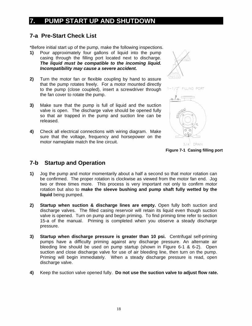
7. PUMP START UP AND SHUTDOWN 7-a Pre-Start Check List *Before initial start up of the pump, make the following inspections. 1) Pour approximately four gallons of liquid into the pump
casing through the filling port located next to discharge. The liquid must be compatible to the incoming liquid. Incompatibility may cause a severe accident.
2) Turn the motor fan or flexible coupling by hand to assure
that the pump rotates freely. For a motor mounted directly to the pump (close coupled), insert a screwdriver through the fan cover to rotate the pump.
3) Make sure that the pump is full of liquid and the suction
valve is open. The discharge valve should be opened fully so that air trapped in the pump and suction line can be released.
4) Check all electrical connections with wiring diagram. Make
sure that the voltage, frequency and horsepower on the motor nameplate match the line circuit.
Figure 7-1 Casing filling port 7-b Startup and Operation 1) Jog the pump and motor momentarily about a half a second so that motor rotation can
be confirmed. The proper rotation is clockwise as viewed from the motor fan end. Jog two or three times more. This process is very important not only to confirm motor rotation but also to make the sleeve bushing and pump shaft fully wetted by the liquid being pumped.
2) Startup when suction & discharge lines are empty. Open fully both suction and
discharge valves. The filled casing reservoir will retain its liquid even though suction valve is opened. Turn on pump and begin priming. To find priming time refer to section 15-a of the manual. Priming is completed when you observe a steady discharge pressure.
3) Startup when discharge pressure is greater than 10 psi. Centrifugal self-priming
pumps have a difficulty priming against any discharge pressure. An alternate air bleeding line should be used on pump startup (shown in Figure 6-1 & 6-2). Open suction and close discharge valve for use of air bleeding line, then turn on the pump. Priming will begin immediately. When a steady discharge pressure is read, open discharge valve.
4) Keep the suction valve opened fully. Do not use the suction valve to adjust flow rate.

19
7-c Shutdown (If the pump is to be shut down for any reason, follow this procedure.) 1) Close discharge valve slowly to prevent water hammer. 2) Shut off the motor. 3) Close the suction valve. 8. DISASSEMBLY AND MAINTENANCE WARNING! Before disassembly, the pump must have the drive "locked out" and be flushed of all dangerous liquids. Follow all Federal, State, Local and company regulations with regard to pump decontamination prior to disassembly and inspection. Ansimag KP Series pumps are provided with a low point casing drain to maximize pump decontamination. Both the long coupled and close coupled KP Series pumps can be pulled back from the casing. Therefore, if permitted by company regulations, pump disassembly and inspection can be conducted on site. Before inspecting, be sure to have a spare casing O-ring on hand to reinstall after the inspection is completed. 8-a. Basic Disassembly for Inspection 1) Stop the pump, lock out the pump starter, shut off all the valves connected to pump,
and drain and decontaminate the pump. Warning! Be sure pump is flushed of dangerous or hazardous liquids and all internal pressure is relieved before opening the pump for inspection.
2) Remove the bolts securing the motor and/or the bracket to the base. Remove the bolts
securing the pump bracket to the rear support. 3) Use the jackscrews to separate the motor and pump drive end at least 10" [250 mm]
back from the pump wet end. Caution! Cantilevered mounts require that the motor fan end be supported. Caution! You are separating the magnet coupling.
3a. Long coupled pumps, remove coupling guard and coupling. Remove bolts securing pump-bearing frame to rear support. Pull bearing frame back from pump wet end.
4) Remove (6) bolts securing the rear support to the back plate. Carefully pull back the rear support and containment shell unit. Caution! Wear protective clothing, eyewear and gloves as required for the pumped liquid. Caution! The impeller assembly contains very powerful magnets. Keep impeller separated from magnetic tools and structures
5) The impeller and shaft may come with the containment shell or remain in the pump casing. Remove the impeller from the casing. Remove the shaft from the impeller. Caution! If the shaft is dropped on a hard surface such as concrete the impact may cause the shaft to break.

20
6) Remove (10) 5/8 X 1.5 bolts that hold the back plate to the pump case. Reinstall the
top bolt, leaving it loose, to protect the back plate from falling. Work the back plate loose from the pump case. Remove the remaining bolt and the back plate.
7) Lift out the volute assembly, including front shaft support and check valve. 8) Remove the check valve and front shaft support from the volute. 8-b. Inspection Checklist Since most wearing parts on a mag drive pump cannot be monitored, it is important to inspect the pump for wear after the initial 500 hours or three months of operation, whichever comes first. Inspect again in six or twelve months, depending on the results of the first inspection. Before inspecting, be sure to have a spare casing O-ring, back plate O-ring and check valve O-ring on hand to reinstall after the inspection is completed. To inspect the pump interior, be sure that the pump has first been flushed of all dangerous liquids. Operating conditions vary so widely that recommending one schedule of preventive maintenance for all centrifugal pumps is not possible. In the case of magnetic drive pumps, particularly of non-metallic pumps, traditional maintenance techniques such as vibration monitoring are not useful or reliable for wet end preventive maintenance. These techniques are effective only for bearing frames (non-liquid contact components) and for motor bearings. For best maintenance results, keep a record of actual operating data such as flow, pressure, motor load, and hours of operation. The length of the safe operation period will vary with different applications and can be determined only from experience. The inspection checklist is as follows: 1) Check for cracks in silicon carbide parts such as the thrust ring and shaft. 2) Check for signs of melting or deforming in the shaft support, bushing and the socket of
the containment shell where the pump shaft is held. Dry-running during initial startup or during operation may cause heat-related deflection or wear of these parts.
3) Inspect the casing liner to be sure there are no signs of abrasion or cuts deeper than
0.05" [1.3 mm]. Pay particular attentionto the notches in the front face of the pump case that locate the volute. Liner cracks may occur if the lining is corroded or placed in an extremely cold place, or if a chemical penetrates the liner and corrodes the outside metal casing. Most liner damage can be spotted visually. To detect hairline cracks, a 15-20 KV electrostatic discharge tester is recommended, which is often used to test lined pipe.
4) The 1.25” carbon bushing should be checked for wear and scoring or grooving. The
dimensions are given in Section 8-c. The SiC bushing will not exhibit wear under normal operation. Polishing on SiC surfaces is a normal condition of running and does not require replacement. However, the inner surface must be checked for cracks, chips or scratches. Verify that the main bushing is tightly pressed into the impeller. It should be impossible to dislodge the bushing by hand. Check for signs of melting around the circumference of the main bushing.

21
5) Check the mouth ring face for wear. The lubrication flutes are reliable indicators of mouth ring wear. If they are not visible, it is time to replace the mouth ring. A part replacement procedure is described in Section 8-d. If a CFR Teflon® mouth ring is used and excessive wear is observed, replace it with a silicon carbide mouth ring.
Figure 8-1 6) Check the impeller vanes for material trapped inside. If any of the five flow paths
become clogged, a hydrodynamic imbalance may cause excessive wear to the mouth ring and main bushing.
7) Check the inner magnet encapsulation for cracks or grooves in excess of 1/32"
[0.8mm]. Fluid inside the magnet area may cause swelling which could wear on the containment shell.
8) Check impeller and inner drive lugs for looseness or swelling due to plastic deformation.
If necessary, removal of the bushing and separation of the impeller and inner drive are required to further inspect the impeller snap fit tabs and contact surfaces of the drive lugs. Replace the impeller if the snap fit tabs or drive lugs are visibly cracked or deformed. Replace the inner drive if the drive lug contact surfaces are swollen or deformed. Note: See Parts Replacement Procedures for additional instruction and tooling.
9) Check for slurry. If the pumped liquid contains slurry, it may build up near the back of
the main bushing. This build-up may cause clogging of the journal bearing area of the main bushing and create a dry-run condition. Estimate the rate of build-up from the first inspection and schedule the unit for future maintenance accordingly.
10) Inspect the containment shell for signs of abrasion. Replace if scratches or grooves in
the inner surface are deeper than 1/32" [0.8mm]. Also replace if the outside has grooves deeper than 0.020 [0.5mm] inches. Inspect the back thrust ring for chips or cracks.
11) Inspect the volute for signs of wear or cracking.
LUBRICATION FLUTES
Fig. 9-1

22
8-c. Detailed Wear Parts Tolerances
A) Main bushing C) Mouth ring
B) Pump shaft Measuring flute depth
Date inspected DIMENSION Original 3mo./500hr 12mo./2000hr Wear dimension / / / / / / Limits 1.25"
A1-A2 Dia. (in) (mm)
1.259" dia 3.20 mm
< 1.284"dia (3.26 mm)
Bushings A3-A4 Dia. (in) (mm)
1.259" dia 3.20 mm
< 1.284"dia (3.26 mm)
B1-B2 Dia. (in) (mm)
1.259" dia 3.20 mm
< 1.284"dia (3.26 mm)
B3-B4 Dia. (in) (mm)
1.259" dia 3.20 mm
< 1.284"dia (3.26 mm)
1.25"
C1-C2 Dia. (in) (mm)
1.256" dia 3.19 mm
> 1.250"dia (3.18 mm)
Shaft C3-C4 Dia. (in) (mm)
1.256" dia 3.19 mm
> 1.250"dia (3.18 mm)
D1-D2 Dia. (in) (mm)
1.256" dia 3.19 mm
> 1.250"dia (3.18 mm)
D3-D4 Dia. (in) (mm)
1.256" dia 3.19 mm
> 1.250"dia (3.18 mm)
Mouth Ring
All mouth ring wear surfaces are made with grooves. These grooves provide cooling flow. When new, the grooves are 0.063" [1.60 mm] deep. The minimum groove depth is 0.031" [0.79 mm]. Replace when grooves are less the 0.031" [0.79 mm].
* Under normal operating conditions, the shaft should last for many years. When the shaft is subjected to dry running, thermal stress cracks may develop. If cracks are found, a replacement shaft is necessary to prevent damage to other pump components. Figure 8-2 Parts Wear Record Format

23
8-d. Parts Replacement Procedures K+ Bushing Installation/Removal Tool
Figure 8-3: K+ Bushing/Installationtool Drawing
Figure 8-4: KP Bushing Installation Figure 8-5: KP Bushing Removal *CAUTION: Support impeller on the shroud, outside of the mouth ring area, to avoid crushing the nose during bushing installation

24
1. After removing the bushing from the impeller, insert the inner drive removal tool (PT0820) into the bushing bore of the impeller. Then while holding the tool in place, drop the tool and the impeller assembly onto a hard surface from a height of approximately six inches. The gap will allow the weight of the inner drive to separate the snap fit tabs while ensuring the inner drive does not contact the hard surface. Caution: Proper use of the tool allows convenient and safe separation of the parts. (Do not pry parts apart. Prying causes damage to the plastic surfaces.)
Figure 8-6: Separation of the impeller and inner drive
2. To remove the mouth ring from the impeller eye use a screwdriver or other flat bladed tool. Note: The silicon carbide mouth rings should be removed only if inspection shows that replacement is required. Removal is likely to damage the SiC mouth ring. KP mouth ring removal
1. Cut exposed TFE O-ring. 2. Pull out the O-ring sections with pliers. 3. Carefully use screwdriver to loosen and remove.
Figure 8-7: Remove Mouth Ring
3. Removing the containment shell from the rear support is a simple process. The two components easily pull apart. Occasionally the stainless steel ring in the containment shell may stick into the rear support. If this happens, rest the rear support bolt lugs on some blocks and gently tap on the stainless steel ring using a long arbor. This will release the containment shell from the rear support Note: 8” KP models must be removed by tapping gently on the dome with a soft hammer.
Figure 8-8: Remove Containment Shell
9. ASSEMBLY 9-a Wet End Assembly
Cut

25
1) To insert shaft support
into volute, place volute on flat, clean surface with suction side down. Use an arbor press to press the shaft support into position. Avoid damaging SiC thrust ring by using something softer like a section of PVC pipe, which is about the same size as the ring. When fully inserted the thrust ring face should lay flush with volute surface.
Figure 9-1 K1104
Figure 9-2 Shaft support into volute (The mandrel from the “Versa-Tool” makes a good pressing arbor. Place a soft material between the mandrel and the silicon carbide face, to prevent damage.)
2) Check Valve: Press O-ring
into face of check valve. It should snap into position. Place valve, O-ring facing out, inside suction end of volute so the arms of the valve rest in the volute’s internal shoulders. Make sure the valve swings freely. If for any reason it hangs up, use sandpaper to remove any burrs. (The ends of the check valve “hinge pin” may need to be ground to fit it in the volute.)
Figure 9-4 KP0 130 Figure 9-5 Assembled Volute 3) Hold assembled volute
by the shaft support and slowly guide into the casing, matching the two lobes @ 180º apart with casing cutouts. Position with prim-ing acceleration hole down and cutwater up.
Figure 9-6 Volute in casing Figure 9-7 Volute into casing
Figure 9-3 KP0130

26
4) Once volute is assembled place large O-ring inside flat area surrounding volute. O-ring will stay in place as shown in figure on the right. Position back plate lining up horizontally four bolt positions. Bolt the back plate to the casing use a 15/16" wrench to tighten the ten 5/8"-11x1.5" hex bolts. Tighten the bolts incrementally in a star pattern to a final torque of 50 ft-lbs (67 N-m.)
Figure 9-8 Placing back plate on casing
5) Impeller consists of parts shown in Figure 9-9.
For Impeller and Inner Drive: Align the drive lugs of the Impeller and Inner Drive and press / snap together. Use arbor press with mouth ring circular riser and flat plate, as needed. Then insert main bushing; no keyway exists. a) O-ring: The O-ring should be
stretched over outer diameter on the mouth ring until locked into groove.
b) Mouth ring: Align the notches on the back side of the mouth ring with the driving “dogs” on the impeller. Press fit the mouth ring into impeller eye on seat provided.
c) Main bushing: For the CFR / ETFE Impeller use the keyless ribbed bushing. For the GFR / PFA Impeller, align the molded key in the impeller bore with the keyway on the main bushing. Press the main bushing into the impeller bore with a drill/arbor press, using a 2" arbor or metal disk between the press and bushing. Insert the cone shaped end of the main bushing first.
Caution: Do not use a hydraulic press, as you cannot feel stoppage when the cone shaped side hits the bottom of the 2-1/8" impeller bore.
Figure 9-9 Impeller assembly (Keyed Bushing shown as the example)
See Figure 8-4. * On older models a separate key was used.

27
6) Mounting rear casing and impeller a) Align the two flats on the shaft with the
mating flats in the containment shell. Insert shaft into socket of rear casing. If necessary, gently drive the shaft into its socket with a soft hammer. .
b) The rear support is clocked with the two
“grooved” ears horizontal. Insert the containment shell into the rear support with the groove in the shaft at the 11:00 O’clock position. If necessary, tap the containment shell into place with a soft hammer until it is evenly seated.
c) Slide impeller assembly onto the shaft. d) Place O-ring in groove of containment
shell. e) Line up the end of the shaft with the bore
of the shaft support in the volute and close the two assemblies together. Using six 1/2"-13 x 1-3/4" hex bolts, bolt the rear support onto the back plate. Tighten the bolts incrementally in a star pattern to a torque of 40 ft-lbs (54 N-m.).
Confirm that the impeller has some axial endplay of 1/16” to 1/8” inside the casing by rocking the assembled wet end back and forth. You should hear the impeller moving inside.
Figure 9-10 Assembling impeller/rear casing

28
9-b Mounting the Outer Drive to the Motor Shaft or Bearing Frame Shaft 1) Place the motor vertically on a worktable or floor so that the shaft is pointing upwards. Be
sure to cover the floor with corrugated cardboard or similar material to prevent damage to the fan cover.
2) If necessary, place the correct motor mounting plate(s) onto the C-face of the motor. Be
sure to align the holes in the motor mounting plate(s) with the threaded holes on the motor.
3) Place the bracket onto the motor mounting plate (or motor face) and line up the bracket
holes with the holes on the motor C-face and the motor mounting plate(s). Use four ½” socket cap screws with lock washers to secure the bracket and motor mounting plate(s) to the motor. Tighten the bolts to snug only. Note that the holes on the motor mounting plate(s) are not tapped. The plates are actually sandwiched between the bracket and the motor.
4) Back out the two set screws on the hub of the outer drive and place the outer drive onto
the motor shaft. Position the outer drive so that the groove in the outer drive lines up with the end of the bracket +1/16, -0” (+1.6mm, -0mm). See Figure 9-11. Figure 9-12 shows the outer drive position with respect to the motor mounting plate for reference. Tighten the set screw to 10 ft-lb (13.6 N-m.) Install the 3/8” NPT pipe plug into the hole on the top of the bracket or bearing frame. This is to keep dirt out of the motor shaft area.
Figure 9-11 Outer drive position with respect to bracket
Drive End

29
6-3/8K3001
Motor frame 143TC/145TC
6-3/8
Motor frame 182TC/184TC
K3002 6-3/8
Motor frame 213TC/215TC
K3002 6-3/8
Motor frame 254TC/256TC
Motor frame 284TSC
K3001 K3002 K3004
Adapter Plate Figure 9-12 Outer Drive position with respect to motor 5) The outer magnet ring, OMR, (P4091X) is interchangeable to maintain the outer drive
mounting positions without removing the adapter hub (P4069X). After the initial installation, the outer magnet ring of the outer drive assembly can be attached to the initial adapter hub position using the two countersunk screws (02-414DJ). Tighten the screws to 60-70 in-lb using a long T handle 5/32” allen wrench. Ensure the polygon drive and mounting surfaces of the adapter hub and OMR are clean and smooth; a light oil may be used for preservation.
Fig. 9-13. Outer Drive Assembly
Adapter Hub and OMR Assembly Installation
30
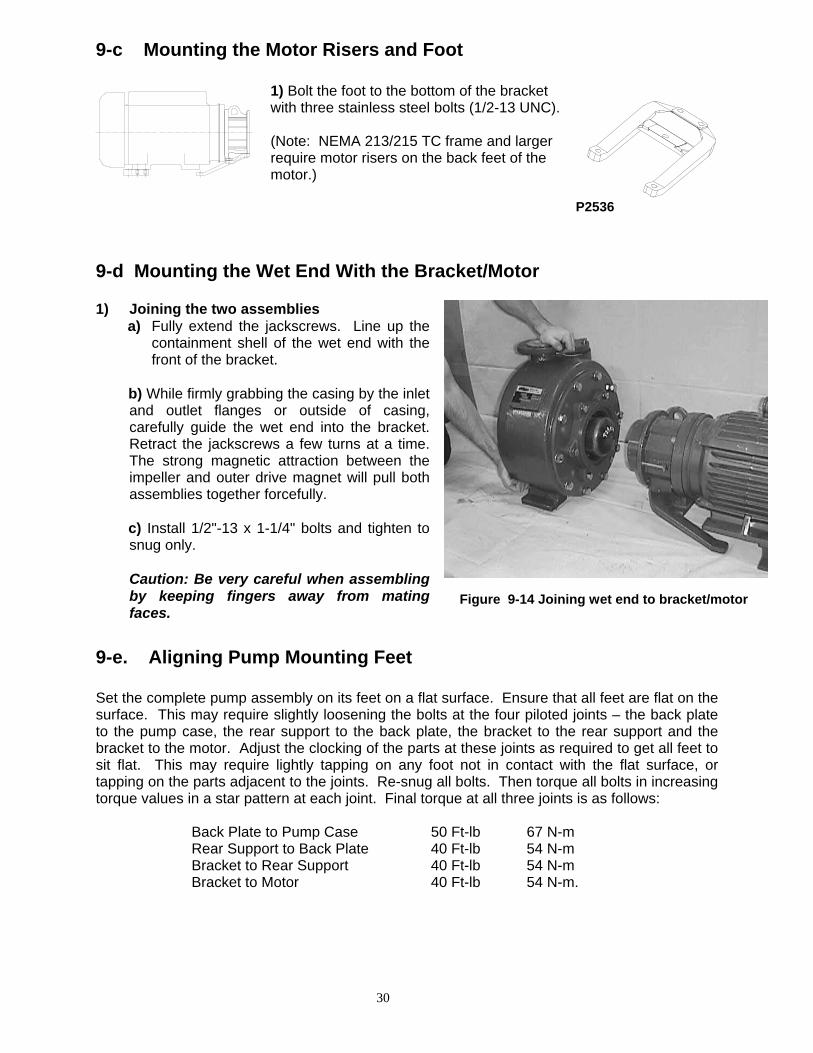
9-c Mounting the Motor Risers and Foot
1) Bolt the foot to the bottom of the bracket with three stainless steel bolts (1/2-13 UNC). (Note: NEMA 213/215 TC frame and larger require motor risers on the back feet of the motor.)
P2536 9-d Mounting the Wet End With the Bracket/Motor 1) Joining the two assemblies
a) Fully extend the jackscrews. Line up the containment shell of the wet end with the front of the bracket.
b) While firmly grabbing the casing by the inlet
and outlet flanges or outside of casing, carefully guide the wet end into the bracket. Retract the jackscrews a few turns at a time. The strong magnetic attraction between the impeller and outer drive magnet will pull both assemblies together forcefully.
c) Install 1/2"-13 x 1-1/4" bolts and tighten to
snug only. Caution: Be very careful when assembling
by keeping fingers away from mating faces.
9-e. Aligning Pump Mounting Feet Set the complete pump assembly on its feet on a flat surface. Ensure that all feet are flat on the surface. This may require slightly loosening the bolts at the four piloted joints – the back plate to the pump case, the rear support to the back plate, the bracket to the rear support and the bracket to the motor. Adjust the clocking of the parts at these joints as required to get all feet to sit flat. This may require lightly tapping on any foot not in contact with the flat surface, or tapping on the parts adjacent to the joints. Re-snug all bolts. Then torque all bolts in increasing torque values in a star pattern at each joint. Final torque at all three joints is as follows:
Back Plate to Pump Case 50 Ft-lb 67 N-m Rear Support to Back Plate 40 Ft-lb 54 N-m Bracket to Rear Support 40 Ft-lb 54 N-m Bracket to Motor 40 Ft-lb 54 N-m.
Figure 9-14 Joining wet end to bracket/motor

31
10. TRIMMING THE IMPELLER
Fig. 10.1 Fig. 10.2 1. Slide impeller and inner drives with lugs onto trimming tool (PT0827) and secure with
support and bolt; Figure 10.1 and 10.2. This tool will prevent lathe jaws from damaging the impeller.
2. Place the trimming tool and impeller into lathe and tighten gently, making sure to center it. 3. Continue with step 3 instruction below. For the GFR / PFA impellers 1) Carefully slide an impeller-trimming
tool (PT0554) into the main bushing assembly area as shown. Secure (PT0555) with tension disc.
2) Place the impeller into the lathe and
gently tighten, making sure it's centered. Be aware of the magnetic attraction with the impeller and lathe jaws.
3) Adjust lathe speed to 700 rpm. 4) Slowly take rough-cuts up to 1/4"
diameter at a time across width B. As you near desired diameter, take smaller and slower cuts for a smoother finish.
5) Final KP impeller modification is
trimming the front shroud 3/4" off the diameter of the finished trim. Clean excess plastic with knife.
6) Chamfer at approximately 0.050" x
45º.
PT0554
PT0555
Figure 10-3 KP+ impeller trimming

32
CFR / ETFE Drive Lug Disassembly Tool (PT0820) Material: UHMW
Fig. 10-4
CFR / ETFE Impeller Trim Arbor (PT0827)
Fig. 10-5

33
To make your own KP impeller trimming tools…
Figure 10-6
Figure 10-7

34
11. BEARING FRAME DISASSEMBLY & MAINTENANCE
Fig. 11-1: Bearing Frame Assembly
11-a. Disassembly
Tools Needed: Adjustable wrench T handle long 3/16” Allen wrench
1) Remove the coupling guard. Disconnect the
flexible coupling between the motor shaft and bearing frame shaft. Drain the oil from the bearing frame using the drain plug on the bottom (8). Unbolt the bearing frame foot from the base plate.
Fig. 11-2: Drain Plug

35
2) Decouple the bearing frame
from the pump by removing the four bolts that connect the bearing frame to the pump rear casing support. Use the jackscrews provided to safely decouple the outer drive from the inner drive. If the bearing frame happens to be an older model without jackscrews, manually pull on the bearing frame to decouple the outer drive from the inner drive.
Fig. 11-3: Bolts to Connect Bearing Frame
Fig. 11-4: Jackscrews to Decouple Drives
3)
Disconnect the outer drive(9) from the shaft by removing the 3/8” NPT plug to expose the two set screws that secure the outer drive to the shaft. Loosen the set screws with the T handle long 3/16” Allen wrench. Note: When a two-piece outer drive assembly is installed, it is possible to remove only the OMR, leaving the hub mounted to the drive shaft. To remove the OMR, remove the two (2) countersunk, flat mounting screws on the interior bottom surface of the OMR. If needed, ¼ - 20 UNC jackscrews are available
Fig. 11-5: Remove 3/8” Plug to Expose Set Screws
Fig. 11-6: Loosen Set Screws

36
4) The outer drive should slide
off the shaft by hand. If not there may be oxidation buildup between the outer drive and the shaft. Use a nonmetallic mechanical puller and the ¼-20 UNC holes provided to extract the outer drive. Do not force the outer drive off the shaft since this could damage the bearings or labyrinth seal. Caution: Use nonmetallic tools to avoid personal injury or damage to the parts.
Fig. 11-7: Slide Outer Drive off Shaft or OMR from
Adapter Hub
Fig. 11-8: Slide Outer Drive off Shaft or OMR from
Adapter Hub 5) Unbolt and remove the
bearing cap.
Fig. 11-9: Unbolt Bearing
Cap Fig. 11-10: Remove
Bearing Cap 6) Extract the shaft by
carefully pulling the shaft towards the motor end. It may be necessary to lightly tap the pump side of the shaft with a hammer against a brass rod to unseat the shaft assembly. There is a tight fit between the shaft assembly and the bearing frame.
Fig. 11-11: Tap Out Shaft Assembly
Fig. 11-12: Remove Shaft Assembly
11-b. Inspection & Maintenance of Bearing Frame

37
The following components should be inspected and replaced as needed: Bearings: The bearings should be cleaned if they are dirty. If they seem to be noisy or rough when rotated they need to be replaced. Check for pits or grooves in the outer race of the bearings and replace the bearing unit if any are found. The oil should be changed whenever the bearings are replaced. Shaft Assembly: Check all rotating smooth machined surfaces for wear and scoring, and replace the shaft assembly if necessary. Labyrinth Seals: Replace the labyrinth seals if they are worn or damaged or if the O-rings are worn. Oil: Ansimag recommends flushing the bearing housing to remove dirt, grit and other impurities that may have entered the bearing housing during shipment or installation. The recommended lubricant is ISO VG 68 synthetic lubricant. Make the first oil change after 400 hours of operation for new bearings if the pump is operating under normal conditions, i.e. experiencing only moderate temperature changes, humidity and dirt. Check the level and condition of the oil through the sight glass on the bearing frame. Check for unusual noise, vibration, and bearing frame oil temperatures.
Amount of oil required: 33 fl.oz. (1.03 qt.) Schedule for Oil Changes: Oil temps below 160 F = 36 months
Oil temps between 160 F and 200 F = 24 months Oil temps between 200 F and 250 F = 12 months * Maintenance intervals based on a clean reservoir protected from contamination. Drain if
contaminated. Also shorten first drain if added to dirty reservoir. 11-c. Assembly of the Bearing Frame [If shaft assembly and labyrinth seals are already assembled skip to Step 5] 1) Start by lightly lubricating the labyrinth seals on
the outside O-ring. Install the labyrinth seal with the expulsion port at the 6 o’clock position facing down, since it works by gravity.
Figure 11-13: Labyrinth Seal w/ Port
at 6 o’clock 2) Use an arbor press and
wide flat arbor (necessary

38
to distribute the load over the entire face) to install the labyrinth seal into the bearing cap. The OD of the seal is stepped - insert the smaller diameter into the bearing cap. Press it in only as far as the first step will allow and avoid angular misalignment. Discard any residual material from the outer O-ring.
Figure 11-14: Install Labyrinth Seal in Bearing
Cap
Figure 11-15: Labyrinth Seal in Bearing Cap
3) Use an arbor press and wide
flat arbor (necessary to distribute the load over the entire face) to install the labyrinth seal into the bearing frame housing cavity, facing the pump side. Insert the smaller diameter of the seal into the cavity. Press it in only as far as the first step will allow and avoid angular misalignment. Discard any residual material from the outer O-ring.
Figure 11-16: Install Labyrinth Seal into Cavity
Fig. 11-17: Labyrinth Seal in Cavity
4) To assemble the shaft assembly, be
aware that the bearing with the lock ring is installed on the motor side. Place the bearing with the lock ring facing down, trying to avoid any angular misalignment and insert the shaft with the longer keyway first until the shaft bottoms out in the bearing. Place the other bearing on the other end of the shaft and press the shaft in until the shaft shoulder bottoms out against the bearing inner race.
Figure 11-18: Shaft Assembly
-Bearings-
Pump Side Shaft
Motor Side

39
5) To press the shaft assembly into the bearing frame carefully stand the bearing frame upright on the pump side end. Lightly lubricate the first step on both sides of the shaft to allow it to slide through the labyrinth seal bore. Drop in the carbon steel wave washer as shown in the drawing. Insert the shaft assembly (with the shortest keyway first) by aligning the bearing with the bearing seat and lightly tapping the end of the shaft with a brass hammer until the shaft assembly bottoms out in the bearing seat.
6) To install the bearing frame cap, lightly apply a small bead of grease in the O-ring groove
in the bearing cap. The grease will keep the O-ring from falling out of its seat when the bearing cap is bolted down. Install the bearing cap over the shaft and bolt down with the four supplied 3/8-16 UNC bolts. Rotate the shaft to insure that the shaft spins freely. Make sure that the rotors on both ends of the bearing frame are seated against the stator by pressing them together with hand pressure.
7) Secure the bearing frame on
a level plane before filling with oil. Remove the breathing tube and filling until the oil level is in the middle of the bull’s eye in the sight glass. If the bearing frame is filled on an uneven surface or tilted afterward, oil will fill the labyrinth seal. Oil will slowly leak out of the seal port at the 6 o’clock position until the labyrinth seal is fully purged.
Fig. 11-21: Remove Breathing Tube
Fig. 11-22: Fill Bearing Frame with Oil
Figure 11-19, Insert Shaft Assembly into
Bearing Frame
Figure 11-20: Tap Shaft Assembly into Place

40
12. DRAWINGS
Figure 12-1 Dimensional Drawing
Model Suction Size (in.) Discharge Size (in.) B CP1 CP2 D E1 G1 G2 O S X Y KP326 3.00" 2.00" 8.00 15.87 27.63 8.25 4.88 16.75 16.75 19.00 9.50 10.75 4.00
41
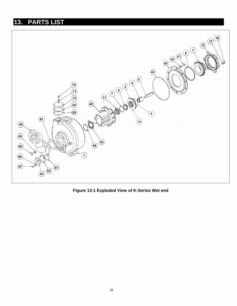
13. PARTS LIST
Figure 13-1 Exploded View of K-Series Wet end
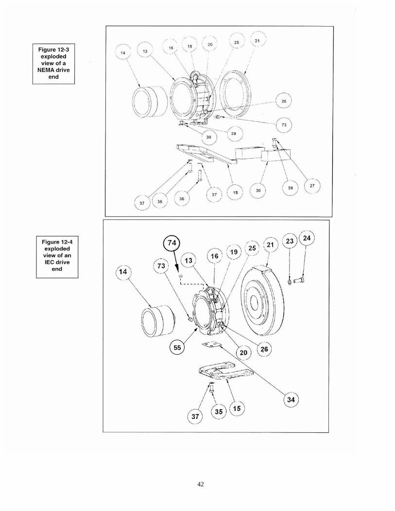
42
55

43
13. PART LIST
13-a Parts List 1 – Wet End Parts - Recommended Spare Parts for all levels of service. Item Part Name Qty Part #
1 KP Casing ETFE w/ ductile iron (ANSI) ETFE w/ductile iron (ISO) ETFE w/ductile iron (JIS)
1 KP0020
RKP0020 RJP0020
2
2a
Fully Encapsulated Drive– CFR-ETFE A-drive 10hp/3600, 5hp/1800 B-drive 15hp/3600, 7.5hp/1800 C-drive 30 hp/3600, 15hp/1800 Impeller – GFR-PFA A-drive 10hp/3600, 5hp/1800 B-drive 15hp/3600, 7.5hp/1800 C-drive 30 hp/3600, 15hp/1800 Impeller Only (CFR / ETFE)
1
1
P2843GE P2843HE P2843IE
P2843J P2843K P2843L P4161
3
4
Containment Shell CFR-ETFE w/CFR-Teflon® CFR-PFA w/CFR-Teflon Inner Drive Only (CFR/ ETFE) A-Drive 10hp / 3600, 5 hp / 1800 B- Drive 15 hp / 3600, 57.5 hp / 1800 C- Drive 30 hp / 3600, 15 hp / 1800
1
1
P2912A P2912B
P4172A P4172B P4172C
5
Mouth Ring CFR-Teflon® SiC
1 K0503 K0507
6 Pump Shaft SiC
1 K0607
ΤΤ 7 O-ring (Mouth Ring)
1 K0706
8 O-ring, Containment Shell Viton® EPDM Gore-Tex® Teflon® Viton®
1 K0801 K0802 P2343
9 Main Bushing CFR / ETFE , SiC Ribbed, Keyless CFR-ETFE/SiC GFR-PFA/SiC Carbon Ribbed, Keyless Carbon
1 P4175 K0907
K0907P
P4175A K0908
11 Shaft Support/Thrust Ring CFR-ETFE/SiC CFR-PFA/SiC
1 K1104
K1104P
12 Rear Support
1 P2363A
17 Lockwasher, Rear Support/Casing
6 HL1/2
18 Hex Bolts, Rear Support/Casing
6 HH1/2x1.75
40 Back Plate ETFE w/ductile iron
1 KP0115
44
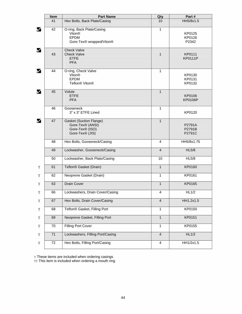
Item Part Name Qty Part # 41 Hex Bolts, Back Plate/Casing
10 HH5/8x1.5
42 O-ring, Back Plate/Casing Viton® EPDM Gore-Tex® wrapped/Viton®
1 KP0125 KP0126 P2342
43
Check Valve Check Valve ETFE PFA
1
KP0111
KP0111P
44 O-ring, Check Valve Viton® EPDM Teflon® Viton®
1 KP0130 KP0131 KP0132
45 Volute ETFE PFA
1 KP0106
KP0106P
46 Gooseneck 3” x 3” ETFE Lined
1 KP0120
47 Gasket (Suction Flange) Gore-Tex® (ANSI) Gore-Tex® (ISO) Gore-Tex® (JIS)
1 P2791A P2791B P2791C
48 Hex Bolts, Gooseneck/Casing
4 HH5/8x1.75
49 Lockwasher, Gooseneck/Casing
4 HL5/8
50 Lockwasher, Back Plate/Casing
10 HL5/8
Τ 61 Teflon® Gasket (Drain)
1 KP0160
Τ 62 Neoprene Gasket (Drain)
1 KP0161
Τ 63 Drain Cover
1 KP0165
Τ 66 Lockwashers, Drain Cover/Casing
4 HL1/2
Τ 67 Hex Bolts, Drain Cover/Casing
4 HH1.2x1.5
Τ 68 Teflon® Gasket, Filling Port
1 KP0150
Τ 69 Neoprene Gasket, Filling Port
1 KP0151
Τ 70 Filling Port Cover
1 KP0155
Τ 71 Lockwashers, Filling Port/Casing
4 HL1/2
Τ 72 Hex Bolts, Filling Port/Casing
4 HH1/2x1.5
Τ These items are included when ordering casings ΤΤ This item is included when ordering a mouth ring

45
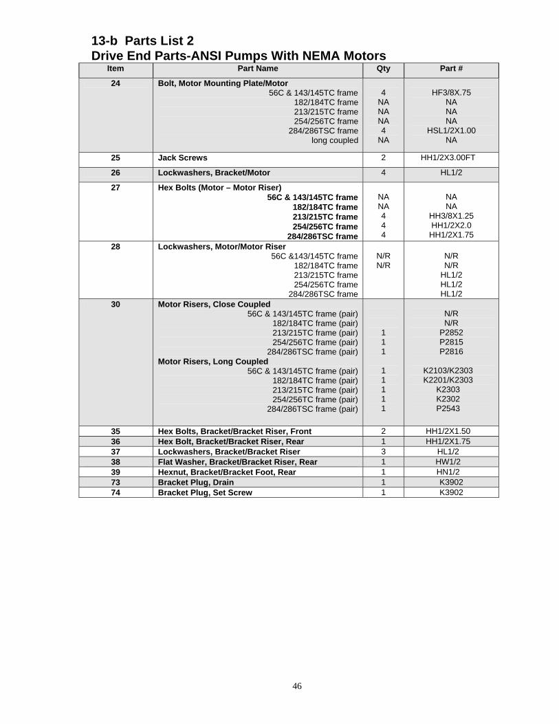
13-b Parts List 2 Drive End Parts-ANSI Pumps With NEMA Motors
Item Part Name Qty Part #
13 Close Coupled Bracket, NEMA 1 P2562
14 Outer Drive Magnet A drive, 56C frame
A drive, 143/145TC frame A drive, 182/184TC frame A drive, 213/215TC frame
A drive, long coupled
B drive, 56C frame B drive, 143/145TC frame
B drive, 182/184TC frame B drive, 213/215TC frame
B drive, 254/256TC & 284/286TSC B drive, long coupled
C drive, 182/184TC frame C drive, 213/215TC frame
C drive, 254/256TC & 284/286TSC C drive, 324/326TSC frame
C-drive, long coupled
1 K1400 K1402 K1401 K1408 K1411
P2236D P2236E K1404 K1403 K1409 K1412
P2236Z P2236F P2236G P2236N P2236L
14a Outer Magnet Ring 1
A Drive P4091A
B Drive P4091B
C Drive P4091C
14b Adapter Hub 1
56C P4069M
143/145TC P4069P
182/184TC P4069W
213/215TC P4069U
254/256TC & 284/286TSC P4069J
324/326TC Contact Ansimag Representative
Long Coupled P4069F
14c Flat Head Countersunk Cap Screws 2 02-414DJ
15 Bracket Foot, CloseCoupled 1 P2536
16 Lockwashers, Rear Support/Bracket 4 HL1/2
19 Hex Bolts, Rear Support/Bracket 4 HH1/2X1.5
20 Hex Bolts, Bracket/Motor 56C & 143/145TC frame
182/184TC frame 213/215TC frame 254/256TC frame
284/286TSC frame
4 HH1/2X1.25 HH1/2X1.50 HH1/2X2.00 HH1/2X2.50 HH1/2X1.25
21 Motor Mounting Plate 56C & 143/145TC frame
182/184TC frame 213/215TC frame 254/256TC frame
284/286TSC frame long coupled
1
NA 1 2 1
NA
K3001
N/R K3002 K3002 K3004
NA
46
13-b Parts List 2 Drive End Parts-ANSI Pumps With NEMA Motors
Item Part Name Qty Part #
24 Bolt, Motor Mounting Plate/Motor 56C & 143/145TC frame
182/184TC frame 213/215TC frame 254/256TC frame 284/286TSC frame long coupled
4
NA NA NA 4
NA
HF3/8X.75
NA NA NA
HSL1/2X1.00 NA
25 Jack Screws 2 HH1/2X3.00FT
26 Lockwashers, Bracket/Motor 4 HL1/2
27 Hex Bolts (Motor – Motor Riser) 56C & 143/145TC frame
182/184TC frame 213/215TC frame 254/256TC frame
284/286TSC frame
NA NA 4 4 4
NA NA
HH3/8X1.25 HH1/2X2.0
HH1/2X1.75 28
Lockwashers, Motor/Motor Riser 56C &143/145TC frame
182/184TC frame 213/215TC frame 254/256TC frame
284/286TSC frame
N/R N/R
N/R N/R
HL1/2 HL1/2 HL1/2
30 Motor Risers, Close Coupled 56C & 143/145TC frame (pair)
182/184TC frame (pair) 213/215TC frame (pair) 254/256TC frame (pair)
284/286TSC frame (pair) Motor Risers, Long Coupled
56C & 143/145TC frame (pair) 182/184TC frame (pair) 213/215TC frame (pair) 254/256TC frame (pair)
284/286TSC frame (pair)
1 1 1
1 1 1 1 1
N/R N/R
P2852 P2815 P2816
K2103/K2303 K2201/K2303
K2303 K2302 P2543
35 Hex Bolts, Bracket/Bracket Riser, Front 2 HH1/2X1.50 36 Hex Bolt, Bracket/Bracket Riser, Rear 1 HH1/2X1.75 37 Lockwashers, Bracket/Bracket Riser 3 HL1/2 38 Flat Washer, Bracket/Bracket Riser, Rear 1 HW1/2 39 Hexnut, Bracket/Bracket Foot, Rear 1 HN1/2 73 Bracket Plug, Drain 1 K3902 74 Bracket Plug, Set Screw 1 K3902

47
13-c Parts List 3 Drive End Parts - ANSI Pumps With IEC Motors
Part Name Qty Part #
13 Bracket, Close Coupled, IEC 1 RK1302 14 Outer Drive Magnet
A drive, IEC B5 80 frame A drive, IEC B5 90 frame
A drive, IEC B5 100/112 frame A drive, IEC B5 132 frame
B drive, IEC B5 80 frame B drive, IEC B5 90 frame
B drive, IEC B5 100/112 frame B drive, IEC B5 132 frame B drive, IEC B5 160 frame C drive, IEC B5 132 frame C drive, IEC B5 160 frame
1 RK1400 RK1401 RK1402 RK1403 P2236H RK1404 RK1405 RK1406 RK1407 P2236V P2236U
14a Outer Magnet Ring 1 A – Drive P4091A B – Drive P4091B C – Drive P4091C
14b Adapter Hub 1 IEC B5 80 P4069N IEC B5 90 P4069R IEC B5 100/112 P4069S IEC B5 132 P4069V IEC B5 160 P4069K
14c Flat Head Counter sunk 2 02-414DJ 15 Bracket Foot – Close Coupled
80, 90,100/112 frame 132 frame 160 frame
1 RK4507 RK4507 RK4507
16 Lockwashers, Rear Support/Bracket 4 HL1/2 19 Hex Bolts, Rear Support/Bracket 4 HH1/2X1.5 20 Hex Bolts, Bracket/Motor Mounting Plate 4 HHM12X35 21 Motor Mounting Plate
80, 90 frame 100/112 frame
132 frame 160 frame
1 RK3002 RK3003 RK3004 RK3005
23 Lockwashers, Motor Mounting Plate/Motor 80 – 100/112 frame
132 frame 160 frame
4 HLM10 HLM12 HLM16
24 Hex Bolts, Motor Mounting Plate/Motor 80, 90, 100/112 frame
132 frame 160 frame
4 HHM10X25 HHM12x30 HHM16X40
25 Jack Screws, M12 2 HHM12X45FT 26 Lockwashers, Bracket/Motor Mounting Plate 4 HLM12

48
13-c Parts List 3 Drive End Parts - ANSI Pumps With IEC Motors
Part Name Qty Part # 35 Hex Bolts, Bracket/Bracket Foot
80, 90, 100/112 frame 132, 160 frame
3 HHM12X40 HHM12x40
37 Lockwashers, Bracket/Bracket Foot 3 HLM12 51 Name Plate, ATEX/CE 1 P4071
55 Earthing Kit, Grounding Lug 1 P4107
73 Bracket Plug, Drain 1 K3902

49
13-d Bearing Frame Parts BEARING FRAME ONLY
Item
#
Part Name
Qty
KP326 Kpi50160 KPj50160
Bearing Frame Assembly P2350 01 Hex Bolt, 3/8-16X7/8 4 HH3/8X0.88 04 SKF Ball Bearing #6207NRJ 1 K3502 05 SKF Ball Bearing #6207 1 K3501 06 Inpro Bearing Isolator 1518-A-09944-0 2 P2434 08 O-Ring #153 1 K3603 10 Wave Spring Washer 1 K3702 11 3/8” NPT Plug 3 K3902 12 1” NPT Sight Window 1 K4002 14 Bearing Frame Shaft 1 P2010 15 ¼” X 1/8” Reducing Bushing 1 K3802 16 1/8” Breathing Tube 1 K3801 17 Bearing Frame Housing 1 P2015 18 Key, ¼ X ¼ X 1-1/4 1 P1632E 19 Key, 3/16 X 3/16 X 1-1/2 1 P1632A 20 Bearing Frame Cap 1 P2564 21 Bearing Frame Oil 1 P2501 26 Hex Bolt, ½-13 X 3.00, Fully Threaded 2 HH1/2X3.00FT

50
14. PREVENTIVE MAINTENANCE AND PERIODIC CHECK UP Since most wearing parts on a mag-drive pump cannot be monitored, it is important to inspect the pump for wear after the initial 500 hours or three months of operation, whichever comes first. Inspect again in six or twelve months depending on the result of the first inspection. Before inspecting, be sure to have a spare casing O-ring on hand to re-install after the inspection is completed. To inspect inside of the pump, be sure that the pump has first been flushed of all dangerous liquids before isolating the pump by closing the inlet and outlet valves.
Operating conditions vary so widely that recommending one schedule of preventive maintenance for all centrifugal pumps is not possible. In the case of magnetic drive pumps, particularly of non-metallic pumps, traditional maintenance techniques, such as vibration monitoring, are not useful or reliable techniques for wet end preventive maintenance. These techniques are effective only for bearing frames (non-liquid contact components) and for motor bearings. For best maintenance results, keep a record of actual operating data such as flow, pressure, motor load and hours of operation. The length of the safe operation period will vary with different applications and can only be determined from experience. The inspection checklist is as follows: 1) Check for cracks in the silicon carbide parts such as the thrust ring and shaft. 2) Check for signs of melting or deforming in the shaft support, main bushing, and the
socket of the rear casing where the pump shaft is held. Dry running during initial startup or during operation may cause heat-related deflection or wear of these parts.
3) Inspect the casing liner to be sure there are no signs of excess abrasion or cuts.
Liner cracks may occur if the lining is corroded or placed in an extremely cold place or if a chemical penetrates the liner and corrodes the outside metal casing. Most liner damage can be spotted visually. To detect hairline cracks, a 15-20 kV electrostatic discharge tester is recommended which is often used to test lined pipe.
4) Check the carbon bushing for wear and scoring or grooving. The SiC bushing will not
exhibit wear under normal operation. Polishing on SiC surfaces is a normal condition of running and does not require replacement. However, check the inner surface for cracks, chips, or scratches. Verify that the main bushing is tightly pressed into the impeller. It should be impossible to dislodge the bushing by hand. Check for signs of melting around the circumference of the bushing.
5) Check the face of the mouth ring for wear. The
lubrication flutes are reliable indicators of wear. If they are not visible, it is time to replace the mouth ring. A more detailed part check up is described later. If a CFR-Teflon® mouth ring is used, and excessive wear is observed, replace it with a silicon carbide mouth ring.
6) Check the impeller vanes for material trapped inside. If any of the five flow paths become clogged, a hydrodynamic imbalance may cause excessive wear to the mouth ring and main bushing.
LUBRICATION FLUTES

51
7) Check the inner magnet encapsulation for cracks or grooves in excess of 1/32". Fluid inside the magnet area may cause swelling which could wear on the containment shell).
8) Check for slurry. If the pumped liquid contains slurry, it may build up near the back of
the main bushing. This build-up may cause clogging of the journal bearing area of the main bushing and create a dry run condition. Estimate the rate of build-up from the first inspection and schedule the unit for future maintenance accordingly.
15. KP ENGINEERING DATA 15-a Priming Time Graphs
KP326
02468
101214161820
0 25 50 75 100 125 150 175 200 225 250 275 300Priming Time (sec.)
6.375" Imp 6.000" Imp 5.750” Imp 5.500" Imp
(Using a 3" Suction Line)
rpm: 3600 SG: 1.0
02468
101214161820
0 10 20 30 40 50 60 70 80 90 100 110 120 130Priming Time (sec.)
6.375" Imp 6.000" Imp 5.750" Imp 5.500" Imp
(Using a 2" Suction Line)
rpm: 3600 SG: 1.0
0
2
4
6
8
10
12
0 100 200 300 400 500 600 700 800Priming Time (sec.)
6.375" Imp 6.000” Imp 5.750" Imp 5.500" Imp
(Using a 3" Suction Line)
rpm: 1800 SG: 1.0
0
2
4
6
8
10
12
0 100 200 300 400 500 600 700Priming Time (sec.)
6.375" Imp 6.000" Imp 5.750" Imp 5.500" Imp
(Using a 2" Suction Line)
rpm: 1800 SG: 1.0
Figure 15-1 Priming time graphs Note: Above priming times were measured with a pump using an internal check valve. Piping was arranged with the pump elevated directly above the liquid source at above specified heights. Height measured is from liquid surface to pump centerline with 1-ft horizontal section. These graphs indicate the average time for priming of ambient water. The priming times shown were determined according to the Hydraulic Institute Seal-less Centrifugal Pump

52
Standards (HI 5.1-5.6 1992) stating: “The priming time shall be the total elapsed time between starting the unit and the time required to obtain a steady discharge gauge reading, or full flow through the discharge nozzle.”
15-b How to Estimate Priming Time and Temperature Rise Due to the wide array of piping schematics and chemical properties, it is important to estimate priming times for each application. Factors that lengthen priming time are: • Piping volume (size and length of suction pipe) • Air leaks in suction piping. • Temperature rise of liquid (As temperature rises the pump’s vacuum capability falls) • Discharge venting (any resistance to air escaping increases priming time) Priming time estimations can be calculated for particular setups by the following procedures. 1) Find static vertical lift: For priming, find the total vertical lift in the suction piping and
multiply by the specific gravity. This number should be equal or less than 20 ft for 3600 rpm and 12ft @ 1750 rpm. Lv= Lift * SG
2) Find priming time for static lift: Refer back to Figure 16-1. Find chart representing
your suction-piping diameter, either a 2" or 3" and motor speed. Use known total vertical lift and read across to appropriate impeller diameter to indicate your preliminary priming time t (sec) for a straight static vertical lift. (Lift shown in curve has one-foot horizontal run.)
3) Calculating priming time for various piping layouts: Equationto use for estimating
priming time for various lengths of vertical or horizontal piping.
tpt = Total priming time before temperature correction. (sec)
t = Time to prime from chart on Figure 16-1. (sec)
Lt = Total suction piping length including both horizontal and vertical (ft).
Lv(ft)Lt(ft)*t(sec)tpt =
Lv = Vertical height of suction pipe measured from liquid surface to centerline of pump multiplying by specific gravity(ft).
4) Calculating temperature rise: Find temperature rise by the following equation taking
into consideration the temperature rise effect of specific heat. Temperature rise can be calculated based on known priming data using water for different motor speeds.
Temperature rise for 3600 rpm Temperature rise for 1750 rpm Tr t 6
cp=
°(min) ( F / min)* Tr t 1cp
=°(min) * ( F / min)
where: t = Time to prime from chart on Figure 16-1. (sec) cp = Specific heat of chemical (btu/lb/°F) or (cal/g/°C)
5) Static priming lift check: Now that the temperature rise is known Tr (°F), we need to assure that the pump will prime at its new temperature. Add value Tr to starting temperature or room temperature giving us the temperature of the pump liquid at the end of the priming cycle. Look up the vapor pressure (mmHg) for your chemical (refer to section 16-e or other source) at the new temperature and find the vapor

53
pressure height Hvp (ft) by converting to an equivalent feet of H20. (Use the unit conversion chart in section 16-f.). Once the vapor pressure is in ft of H20, add the value to the previously determined Lv. If Hvp(ft) + Lv(ft) is greater than 20 ft, application is not recommended.
6) New corrected priming time: Use the adjusted vertical lift from step 5 to find a new time tcpt (sec) and insert into the equation from step 3 to recalculate priming time.
tcpt = tpt(sec)*
EXAMPLE: Assume: • Application: 33.6 % Hydrochloric Acid • Starting temperature: 68°F • Specific gravity (SG): 1.171 • Total piping length (Lt) = 36 (ft) • Static vertical lift =11 (ft) • Impeller diameter = 6.000" • Suction pipe diameter = 3 (in) • Motor speed = 3600 rpm
Find priming time and temperature rise of 33.6% HCl with above conditions. 1) Find Lv: Lv =11 x 1.171 Lv=12.9 ft 2) Use priming time chart (Figure 16-1) to find time for 12.9 ft with 6.000" impeller @ 3600 rpm. T = 80 sec 3) Calculate the total priming time before temperature correction.
(ft)(ft)(sec)
LvLtttpt ∗= tpt 80 36
12.9= ∗(sec) ( ft)
( ft)
tpt = 223.3 sec or 3.72 minutes 4) Calculate the corrected temperature rise of HCl 33.6% including specific heat
Tr 3.72 60.591
=°
°(min) * ( F / min)
(btu / lb/ F) Tr = 37.7 °F
5) Static priming lift check Temperature when finishing priming: 68°F + 37.7°F = 105.7 °F Convert vapor pressure of HCl 33.6 % at 105.7°F to feet of water
Hvp= 148 mmHg * 0.04457 Hvp = 6.6 ft Check: Hvp + Lv ≤ 20 ft. 6.6 ft +12.9 ft = 19.5 ft (If lift is less than 20 ft, application is still recommended.)
6) Calculate the total corrected priming time tcpt using steps 2 & 3. From Figure 16-1 priming time with 19.5-ft lift with 6.000" impeller @ 3600 rpm is 129 seconds.
Lt(ft)
Lv(ft

54
tcpt = tpt(sec)*Lv(ft)Lt(ft)
tcpt = 129(sec)*12.9(ft)36(ft)
tcpt = 360 seconds
*This pump will prime in approximately 6 minutes with a temperature rise of 37.7°F.
15-c Temperature Rise Graph Using a Thermowell
KP Temperature Rise using Rotomolded Thermowell
water @ 3600 rpm
0
20
40
60
80
100
120
140
160
180
0 20 40 60 80 100 120 140Time (minutes)
Thermowell Actual
Figure 15-2 (Note: Figure 15-2 temperature rise curve was generated using water with starting temperature of 62°F. The pump was filled through the filling port, using a full-size impeller-6.450". The suction valve remained closed and the discharge valve remained open during the entire test. Temperature rise measurements: Actual- thermocouple in liquid, Thermowell- thermocouple inside a 316 SS rotolined thermowell.) The main purpose for monitoring the temperature rise in the KP casing is to eliminate the risk of excessive overheating while priming in the event of a system problem. The thermowell is constructed of 316 SS, which is threaded directly into the KP casing, located next to the suction flange. With the wide range of processing liquids, chemical compatibility was achieved by lining the thermowell with ETFE, the same material as the casing lining. Its availability provides pump protection by adding thermal monitoring options for a temperature-activated

55
switch to limit the pump from high temperatures or as a probe location for visual monitoring for the operator to use. When using the thermowell for a high temperature safety switch, set the maximum allowable temperature to be 225°F. This will protect the pump from unusual operation, which would cause overheating. 15-d NPSH NPSH (net positive suction head) is the total suction head (in feet of liquid absolute) being pumped at the pump’s centerline or impeller eye. There are two forms of NPSH and it is important to differentiate between them. NPSHR means net positive suction head required which represents the pump requirements for normal operation. Data for the required NPSH is accumulated through factory testing by the manufacturer for each pump size and speed. The NPSHR increases with greater pump speed and capacity. NPSHA means net positive suction head available from the piping supply system. NPSHA must always be greater than NPSHR to maintain pump performance. When considering a centrifugal self-priming pump for an application, available NPSH should be thoroughly understood and calculated. A loss of efficiency and capacity along with cavitation and vibration will occur if suction conditions are insufficient. This can lead to pump failures. NPSHA can be determined by some simple calculations using the following equation.
Ha = Hp ± Hs - Hvp - Hfl
Ha = Available NPSH (feet of liquid) Hp = Absolute pressure on the surface of the suction liquid. For self-priming
applications, all tanks should be vented to atmospheric pressure or padded. Hs = Static head measured from the surface of the liquid above (+) or below (-)
the centerline of the pump. (feet of liquid) Hvp = Absolute vapor pressure of the liquid at the temperature it is being pumped.
(feet of liquid) Hfl = Friction head loss is the sum of all friction losses in the suction line at the
specified flow rate measured from the suction source to the suction pump flange. (feet of liquid)
Example 1: Suction Lift Assume the application is 28.9% hydrochloric acid @ 68°F and flow is 150 gpm, vapor pressure is 7.75 mmHg and specific gravity is 1.144 with a vertical lift of 9 ft. The suction tank is vented and the barometric pressure reads 29.75 inches of mercury. There is a total of 15 ft of 3" pipe with three 90° flanged elbows and one full port ball valve. What's the available NPSH under these conditions?
1) Determine Hp
ft1.144
1.32*29.75 Hp absolute) liquid, of (feet SG
1.32*inHg Hp 33.34==== (Equation converts inches of mercury to feet of liquid)
2) Hs = -9 ft

56
3) Hvp= vapor pressure of 28.9% HCl @ 68°F = 0.30 in Hg
ft1.144
1.32*0.31 Hvp liquid) of (feet SG
1.32*inHg Hvp 36.0====
Example 1: (Continued) 4) Hfl = Head loss per 100 ft (based on flow of water in new steel pipe) = 5.13, velocity =
6.51 ft/sec (Note: pipe friction loss & resistance coefficient for fittings were found in Cameron Hydraulic Data)
pipe loss = 15 ft * 5.13/100 = 0.77 ft
valve loss = (Resistance coefficient K=0.05) 2gv*K=H
2
2(32.2)6.51*0.05=H
2
H=0.03 ft
elbow loss = K=0.36 H = K * v2g
2
H = 0.36* 6.512(32.2)
2
H = 0.24 * 3 = 0.72 ft
Hfl = 0.77 + 0.03 + 0.72 = 1.52 ft
5) Calculate available NPSH: Ha = Hp ± Hs - Hvp - Hfl Ha = 29.38 - 9 - 0.31 - 1.52 Ha = 18.55 ft
6) Now that the available NPSH is known for example 1 at 18.55 ft, we need to check the
pumps required NPSH to assure that NPSHA > NPSHR. Refer to the KP Performance Curve manual on NPSH and find the proper speed & suction pipe diameter curve as shown in Figure 16-3. For this example 1, the 18.55-ft calculated is clearly above the 15 ft @ 150 gpm shown in Figure 16-3. The pump will have no trouble functioning properly at the desired flow unless available NPSH falls below the 15 ft required.
KP NPSH Curve3500 rpm S G = 1.00
Capacity (U.S. Gallons Per Minute)
0
5
10
15
20
25
30
35
0 50 100 150 200 250 300
3" Inlet
Figure 15-3

57
EXAMPLE 2: (Tank Unloading) Assume the application is 93.19% sulfuric acid @ 68°F at 160 gpm. Vapor pressure is 0.3 mmHg and specific gravity is 1.835, viscosity is 22 cP. Once the pump primes there is actually 10 ft of static head on the vented suction tank car. As the tank car finishes unloading, static head drops to 4 ft. Barometric pressure reads 29.3 inches of mercury. There is a total of 36 ft of 3" pipe with five 90° flanged elbows and two full port ball valves. What is the available NPSH under these conditions at the beginning of pumping and when the car nears empty?
1) Determine Hp
ft1.835
1.32*29.3 Hp absolute) liquid, of (feet SG
1.32*inHg Hp 1.18====
2) Hs = 10 ft. 3) Hvp = vapor pressure of 93.19% sulfuric acid @ 68°F = 0.01 inHg
ft1.835
1.32*0.01 Hvp liquid) of (feet SG
1.32*inHg Hvp 01.0====
4) Hfl = Head loss per 1000ft (based on friction loss for viscous liquids flowing through a
new steel pipe) = 98.2 velocity = 6.94 ft/sec (Note: pipe friction loss & resistance coefficient for fittings were found in Cameron Hydraulic Data)
Pipe loss = 36 ft * 98.2/1000 = 3.5 ft
Valve loss = K=0.05 H = K * v2g
2
H = 0.05* 6.942(32.2)
2
H = 0.04 * 2 = 0.08 ft
Elbow loss = K=0.36 H = K * v2g
2
H = 0.36* 6.942(32.2)
2
H = 0.27 * 5 = 1.35 ft
Hfl = 3.5 + 0.08 + 1.35 = 4.93
5) Calculate available NPSH: NPSHA with 10 ft static head Ha = Hp ± Hs - Hvp - Hfl Ha = 18.1 + 10 - 0.01 - 4.93 Ha = 23.16 ft NPSHA with 4 ft static head Ha = Hp ± Hs - Hvp - Hfl Ha = 18.1 + 4 - 0.01 - 4.93 Ha = 17.16 ft 6) Refer to the KP Performance Curve manual on NPSH and find the proper speed &
suction pipe diameter curve as shown in Figure 15-3. For this example 2, the pump should have no trouble pumping 160 gpm when the tank car is full however, when

58
nearing empty the available NPSH drops close to the required NPSH at 16 ft. Any alterations in the factors affecting available NPSH will change the pump’s capabilities. It is important to maintain sufficient available NPSH so the pump does not lose prime by cavitation before the tank car is empty.
Let’s assume that if the full-port ball valves were actually reduced-port valves and the barometric pressure dropped to 28.5 inHg. The ball valve reduces the 3" pipe to a 2" diameter seat with a 40° conical inlet and expands with a 40° conical outlet back to the 3" pipe inner diameter. How does this affect available NPSH?
Adjust Hp
ft1.835
1.32*28.5 Hp liquid) of (feet SG
1.32*inHg Hp 6.17====
Adjust Hfl (Note: Resistance coefficients for fittings were found in Cameron Hydraulic Data)
valve contraction friction coefficient K=? K
..0.5 1d1
2
d22
sinθ
2K ..0.5 1
22
32sin
402 K=0.16
valve enlargement friction coefficient
K=? K ..2.6 sinθ
21
d12
d22
2
K ..2.6 sin402
122
32
2
K=0.1
valve loss = K= 0.16 + 0.10=0.26 * 2= 0.52 H = K * v2g
2
H = 0.52 * 15.32(32.2)
2
H = 1.9 ft
Use the new value for Hp and substitute new the valve loss into step 4, then recalculate available NPSH:
NPSHA with 10 ft static head Ha = Hp ± Hs - Hvp - Hfl Ha = 17.6 + 10 - 0.01 - 6.75 Ha = 20.84 ft NPSHA with 4 ft static head Ha = Hp ± Hs - Hvp - Hfl Ha = 17.6 + 4 - 0.01 -6.75 Ha = 14.84 ft
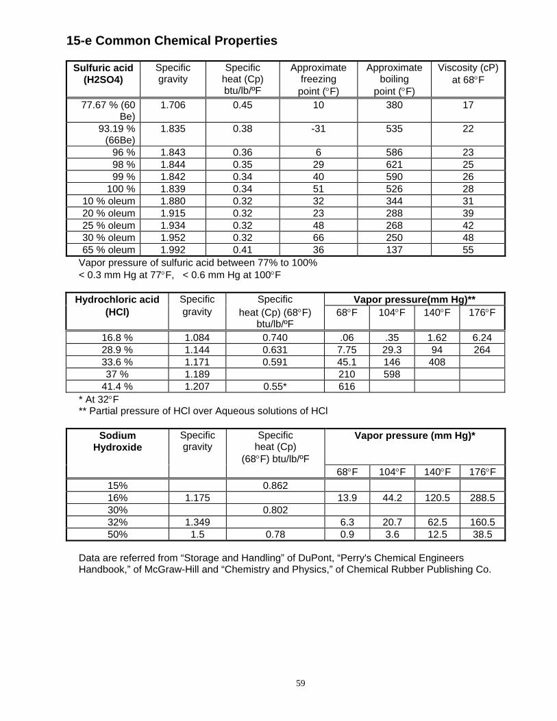
59
15-e Common Chemical Properties
Sulfuric acid (H2SO4)
Specific gravity
Specific heat (Cp) btu/lb/ºF
Approximate freezing
point (°F)
Approximate boiling
point (°F)
Viscosity (cP) at 68°F
77.67 % (60 Be)
1.706 0.45 10 380 17
93.19 % (66Be)
1.835 0.38 -31 535 22
96 % 1.843 0.36 6 586 23 98 % 1.844 0.35 29 621 25 99 % 1.842 0.34 40 590 26
100 % 1.839 0.34 51 526 28 10 % oleum 1.880 0.32 32 344 31 20 % oleum 1.915 0.32 23 288 39 25 % oleum 1.934 0.32 48 268 42 30 % oleum 1.952 0.32 66 250 48 65 % oleum 1.992 0.41 36 137 55
Vapor pressure of sulfuric acid between 77% to 100% < 0.3 mm Hg at 77°F, < 0.6 mm Hg at 100°F
Hydrochloric acid Specific Specific Vapor pressure(mm Hg)**
(HCl) gravity heat (Cp) (68°F) btu/lb/ºF
68°F 104°F 140°F 176°F
16.8 % 1.084 0.740 .06 .35 1.62 6.24 28.9 % 1.144 0.631 7.75 29.3 94 264 33.6 % 1.171 0.591 45.1 146 408 37 % 1.189 210 598
41.4 % 1.207 0.55* 616 * At 32°F ** Partial pressure of HCl over Aqueous solutions of HCl
Sodium
Hydroxide Specific gravity
Specific heat (Cp)
(68°F) btu/lb/ºF
Vapor pressure (mm Hg)*
68°F 104°F 140°F 176°F 15% 0.862 16% 1.175 13.9 44.2 120.5 288.5 30% 0.802 32% 1.349 6.3 20.7 62.5 160.5 50% 1.5 0.78 0.9 3.6 12.5 38.5
Data are referred from “Storage and Handling” of DuPont, “Perry's Chemical Engineers Handbook,” of McGraw-Hill and “Chemistry and Physics,” of Chemical Rubber Publishing Co.

60
15-f Unit Conversions Flow (capacity)
gpm (US) m3/h L/min gpm (UK) 1 0.2271 3.785 0.8327 4.403 1 16.6 3.666 0.2642 0.06 1 0.2200 1.201 0.2727 4.5458 1
gpm (US) x 0.2271 = m3/h L/min x 0.2642 = gpm (US) m3/h x 4.403 = gpm (US) gpm (US) x 3.785 = L/min m3/h x 16.6 = L/min L/min x 0.06 = m3/h
Head ( pressure / vacuum ) ft (H²O) m (H²O) psi kg/cm2 KPa inch Hg mm Hg bar
1 0.3048 0.4335 0.03048 2.989 0.8851 22.48 0.02987 3.281 1 1.422 0.100 9.807 2.904 73.76 0.3685 2.307 0.7031 1 0.07031 6.895 2.042 51.87 0.0690 32.83 10.01 14.23 1 98.07 29.04 737.6 3.685 0.3349 0.1020 0.1450 0.01020 1 0.2961 7.521 0.01 1.132 0.3450 0.491 0.03443 3.377 1 25.4 0.0339
0.04457 0.5339 0.01933 0.001356 0.1330 0.03937 1 0.005 33.5 2.714 14.50 0.2714 100 29.5 200 1
ft (in water) x 0.3048 = m (in water) psi x 2.307 = ft (in water) m (in water) x 3.2808 = ft (in water) ft (in water) x .433 = psi kg/cm2 x 0.328 = ft (in water) psi x 6.895 = kPa ft (in water) x 3.049 = kg/cm2 KPa x 0.1450 = psi
Volume ft3 m3 liter gallon (US) gallon (UK) lbs of water 1 0.02832 28.32 7.481 6.229 62.44
35.31 1 1000 264.2 220.00 2205 0.03531 0.001 1 0.2642 0.2200 2.204 0.1337 0.003785 3.785 1 0.8327 8.347 0.1606 0.004545 4.548 1.201 1 10.025
0.01620 0.0004537 0.4537 .1198 0.09975 1 Temperature conversions
°F °C °F °C °F °C °F °C °F °C °F °C °F °C °F °C Δ°F Δ°C
-60 -51 0 -18 60 15.6 120 48.9 180 82.2 240 116 300 149 360 182 1 0.6-55 -48 5 -15 65 18.3 125 51.7 185 85.0 245 118 305 152 365 185 2 1.1-50 -46 10 -12 70 21.1 130 54.4 190 87.8 250 121 310 154 370 188 3 1.7-45 -43 15 -9.4 75 23.9 135 57.2 195 90.6 255 124 315 157 375 191 4 2.2-40 -40 20 -6.7 80 26.7 140 60.0 200 93.3 260 127 320 160 380 193 5 2.8-35 -37 25 -3.9 85 29.4 145 62.8 205 96.1 265 129 325 163 385 196 6 3.3-30 -34 30 -1.1 90 32.2 150 65.6 210 98.9 270 132 330 166 390 199 7 3.9-25 -32 35 1.67 95 35.0 155 68.3 215 102 275 135 335 168 395 202 8 4.4-20 -29 40 4.44 100 37.8 160 71.1 220 104 280 138 340 171 400 204 9 5.0-15 -26 45 7.22 105 40.6 165 73.9 225 107 285 141 345 174 405 207 10 5.6-10 -23 50 10.0 110 43.3 170 76.7 230 110 290 143 350 177 410 210 11 6.1
-5 -21 55 12.8 115 46.1 175 79.4 235 113 295 146 355 179 415 213 12 6.7°F=1.8 °C+32 °C=0.55 x (°F - 32)

61
16 SHIPPING WEIGHTS
16-a Pump Weight
KP326 NEMA
T and TC Frame Size Close
Coupled Long
Coupled lbs kg lbs kg
143 - 145 240 109 --- --- 182 - 184 237 108 238 108 213 - 215 246 112 --- --- 254 - 256 257 117 --- --- 284 TSC 264 120 --- --- Wet end only 206 lbs 94 kg
16-b Motor Weight Refer to manufacturer's catalog
17. SPECIFICATIONS
Maximum Viscosity 1200 SSU Maximum Operating Temperature
250°F Maximum Internal Pressure 285 psi Minimum Operating Temperature -20F
18. INACTIVE PARTS
2 Impeller – CFR-ETFE A-drive 10hp/3600, 5hp/1800
B-drive 15hp/3600, 7.5hp/1800 C-drive 30 hp/3600, 15hp/1800
1 P2843G P2843H P2843I

ANSIMAG, 14845 W. 64th Avenue, Arvada, CO 80007, USA Phone: (303)425-0800 Fax: (303)425-0896
www.Sundyne.com KP Installation&Maintenance, July, 2007
JH Process Equipment Inc. | 617 Jeffers Circle, Exton, PA 19341 | 610-903-0900 | www.jhprocess.com