installation & maintenance manual col-met … booth manual...installation & maintenance...
TRANSCRIPT
Installation &Maintenance Manual
Col-Met Spray Booths1635 Innovation Drive.
Rockwall Tx. 75032www.colmetsb.com
888-452-6684

Contents 1. Introduction .......................................................................................................... 5
1.1 Introduction ............................................................................................................................. 5 1.2 Receiving, Unpacking, And Reporting Missing Items............................................................... 5 1.3 Back-Charges For Material And Labor .................................................................................... 6
2. Safety ..................................................................................................................... 72.1 Safety Alert Symbol And Signal Words ........................................................................................ 7
2.1.1 Assembly Hazards .......................................................................................................... 7 2.1.2 Operational Hazards ....................................................................................................... 8 2.1.3 Maintenance Hazards ..................................................................................................... 9 2.1.4 Fire Hazard ...................................................................................................................... 9
2.2 Safety Decals ......................................................................................................................... 10 2.3 NFPA 33 ................................................................................................................................. 11
3. COMPONENT DESCRIPTION .............................................................................. 143.1 Compliance To Applicable Codes ........................................................................................... 14 3.2 Material Specifications ........................................................................................................... 14 3.3 General Description ............................................................................................................... 14
3.3.1 Paint Area ...................................................................................................................... 14 3.3.2 Exhaust Fan And Chambers .......................................................................................... 14 3.3.3 Product Doors ................................................................................................................ 14 3.3.4 Door Latch ..................................................................................................................... 14 3.3.5 Door Limit Switch ........................................................................................................... 14 3.3.6 Air Make Up Unit (Optional) ........................................................................................... 15
3.4 Exhaust Filter Manometer ...................................................................................................... 15 3.5 Air Solenoid Valve ........................................................................................................................... 15 3.6 Control Panel ......................................................................................................................... 15
4. Installation ........................................................................................................... 164.1 General .............................................................................................................................. 16 4.2 Preliminary ......................................................................................................................... 16 4.3 Planning Ahead .................................................................................................................. 16 4.4 Booth Assembly ................................................................................................................. 17 4.5 Lights ................................................................................................................................. 18 4.6 Manometer ......................................................................................................................... 20 4.7 Exhaust Filter Installation ................................................................................................... 23 4.8 Intake Filter Installation ...................................................................................................... 23 4.9 Motor Installation................................................................................................................ 24 4.9.1 Mounting ........................................................................................................................ 24 4.9.2 Install Sheaves And Fan Belts ....................................................................................... 24 4.9.3 Electrical ........................................................................................................................ 24
4.10 Tubeaxial Fan .................................................................................................................. 26 4.11 Exhaust Duct Installation .................................................................................................. 26 4.12 Product Door .................................................................................................................... 27 4.13 Access Door Limit Switch Installation ............................................................................... 28 4.14 Access Door Latch Installation.................……………...….…………………………….……29 4.15 Product Door Limit Switch Installation .............................................................................. 30 4.16 Solenoid Wiring Diagram ................................................................................................. 31
www.colmetsb.com Page 3 888-452-6684
COL-MET Spray Booths
4.17 Checklist……….……………………………………………………...…………………………….32
5. Maintenance ........................................................................................................ 335.1 Maintenance Interval Cart ...................................................................................................... 33 5.2 Daily ...................................................................................................................................... 34
5.2.1 Inspect Filters ................................................................................................................ 34 5.2.2 Filter Maintenance ......................................................................................................... 34 5.2.3 Determine Filter Condition ............................................................................................. 34
5.3 Every Two Months ................................................................................................................. 34 5.3.1 Lubricate Door Latches ................................................................................................. 34
5.4 Every Six Months ................................................................................................................... 35 5.4.1 Check Fan Belts ............................................................................................................ 35
5.5 Every Year ............................................................................................................................................ 35 5.5.1 Inspect Motor ................................................................................................................ 35 5.5.2 Inspect Fan Wheel ........................................................................................................ 35 5.5.3 Inspect And Clean Air Solenoid Valve .................................................................................. 36
6 Warranty ................................................................................................................... 376.1 Returning Items For Credit.................................................................................................... 37 6.2 Back Charges For Material And Labor .................................................................................. 38
www.colmetsb.com Page 4 888-452-6684
COL-MET Spray Booths
1. INTRODuCTION
1.1 IntroductIon
Thank you for purchasing a Col-Met Spray Booth.
Read and understand this manual before using your booth and follow all of the safety instructions. Keep this manual with your booth at all times.
This manual explains the assembly and routine maintenance of the Col-Met spray booth.
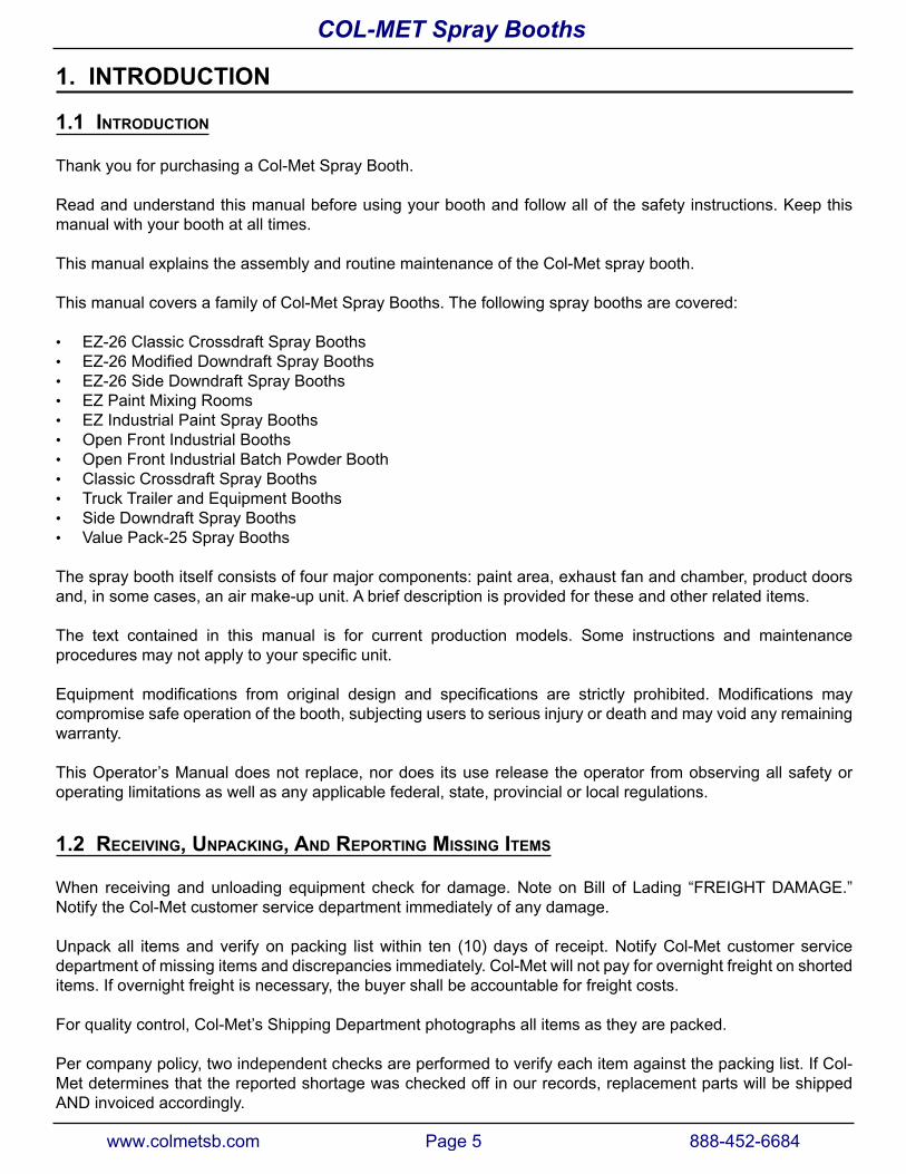
This manual covers a family of Col-Met Spray Booths. The following spray booths are covered:
• EZ-26 Classic Crossdraft Spray Booths• EZ-26ModifiedDowndraftSprayBooths• EZ-26 Side Downdraft Spray Booths• EZ Paint Mixing Rooms• EZ Industrial Paint Spray Booths• Open Front Industrial Booths• Open Front Industrial Batch Powder Booth• Classic Crossdraft Spray Booths• Truck Trailer and Equipment Booths• Side Downdraft Spray Booths• Value Pack-25 Spray Booths
The spray booth itself consists of four major components: paint area, exhaust fan and chamber, product doors and, in some cases, an air make-up unit. A brief description is provided for these and other related items.
The text contained in this manual is for current production models. Some instructions and maintenance proceduresmaynotapplytoyourspecificunit.
Equipment modifications from original design and specifications are strictly prohibited. Modifications maycompromise safe operation of the booth, subjecting users to serious injury or death and may void any remaining warranty.
This Operator’s Manual does not replace, nor does its use release the operator from observing all safety or operating limitations as well as any applicable federal, state, provincial or local regulations.
1.2 receIvIng, unpackIng, and reportIng MIssIng IteMs
When receiving and unloading equipment check for damage. Note on Bill of Lading “FREIGHT DAMAGE.” Notify the Col-Met customer service department immediately of any damage.
Unpack all items and verify on packing list within ten (10) days of receipt. Notify Col-Met customer service department of missing items and discrepancies immediately. Col-Met will not pay for overnight freight on shorted items. If overnight freight is necessary, the buyer shall be accountable for freight costs.
For quality control, Col-Met’s Shipping Department photographs all items as they are packed.
Per company policy, two independent checks are performed to verify each item against the packing list. If Col-Met determines that the reported shortage was checked off in our records, replacement parts will be shipped AND invoiced accordingly.
www.colmetsb.com Page 5 888-452-6684
COL-MET Spray Booths
Items that can be shipped UPS usually take from one to three days to receive, depending on distance. Items too largeforUPSwillshipviacommonfreight.Thisshippingmethodtypicallytakesfromonetofivedaystoreachthe destination.
During the warranty period, Col-Met Spray Booths will repair or replace, free of charge, any parts that Col-MetSprayBoothshasverifiedtobedefectiveinmaterialsorworkmanship.Ifinspectionoftheequipmentdoesnotdisclose any defect in workmanship of material, repairs will be made at a reasonable charge, which will include the costs of labor, materials and transportation.
1.3 Back-charges For MaterIal and laBor
Col-Met Spray Booths shall not be held responsible for any Back-Charges incurred for materials or labor without prior written consent.
Should a problem arise, please notify Col-Met immediately. Once the issue is investigated, should costs be incurred,anamountshallbeagreedonbybothpartiesbefore-hand.DoNOTattemptmodificationsorrepairswithout prior consent as this may void further warranty repairs or credit. Col-Met will not accept back-charges associated with late delivery.
Please address warranty repairs to:
Col-Met Spray Booths1635 Innovation DriveRockwall, TX 75032Attention: Customer Service
For all electrical and gas control service issues please direct to:
Col-Met Spray Booths1635 Innovation DriveRockwall, TX 75032Attention: Controls Engineering Manager
www.colmetsb.com Page 6 888-452-6684
COL-MET Spray Booths
2. SafETy
2.1 saFety alert syMBol and sIgnal Words
Before assembling, operating or servicing the spray booth, you must read, understand and follow the instructions and safety warnings in this manual. Your spray booth may not be equipped with some of the optional equipment described in this manual.
NEVER aLLOW aNyONE TO OPERaTE THIS EQuIPMENT WITHOuT PROPER TRaINING!
The safety information in this manual is denoted by the safety alert symbol: ^
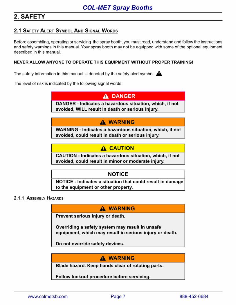
The level of risk is indicated by the following signal words:
^ DaNGERDaNGER - Indicates a hazardous situation, which, if not avoided, WILL result in death or serious injury.
^ WaRNINGWaRNING - Indicates a hazardous situation, which, if not avoided, could result in death or serious injury.
^ CauTIONCauTION - Indicates a hazardous situation, which, if not avoided, could result in minor or moderate injury.
NOTICENOTICE - Indicates a situation that could result in damage to the equipment or other property.
2.1.1 asseMBly hazards
^ WaRNINGPrevent serious injury or death.
Overriding a safety system may result in unsafe equipment, which may result in serious injury or death.
Do not override safety devices.
^ WaRNINGBlade hazard. Keep hands clear of rotating parts.
follow lockout procedure before servicing.
www.colmetsb.com Page 7 888-452-6684
COL-MET Spray Booths
^ WaRNINGPrevent serious injury or death.
use adequate lifting devices to raise, move and install booth components.
^ WaRNINGPrevent serious injury or death.
Electrical installations must be performed by qualified electricians.
Installation must conform to all national, local, and provincial codes and standards.
2.1.2 operatIonal hazards
^ WaRNINGPrevent serious injury or death.
Do not operate machine with guards and/or covers open or removed.
^ WaRNINGPrevent serious injury or death.
Only trained and qualified personnel may operate booth.
^ WaRNINGPrevent serious injury or death.
Never operate spray booth while under the influence of drugs, alcohol or while feeling ill.
^ WaRNINGPrevent serious injury or death.
always wear personal protective equipment (PPE) appropriate for job.
Read Material Safety Data Sheet for products used in spray booth.
www.colmetsb.com Page 8 888-452-6684
COL-MET Spray Booths
^ WaRNINGShock hazard.
Only a qualified electrician may open electrical control cabinet.
Disconnect and lockout / tagout all power sources before adjusting, repairing, or cleaning booth.
2.1.3 MaIntenance hazards
^ WaRNINGPrevent serious injury or death.
Disconnect and lockout / tagout all power sources before adjusting, repairing, or cleaning booth.
^ WaRNINGPrevent serious injury or death.
Service, maintenance and adjustments must be performed by trained and qualified personnel.
^ WaRNINGBurn hazard. Do not touch hot parts.
allow to cool before servicing.
^ WaRNINGPrevent serious injury or death.
always wear personal protective equipment (PPE) appropriate for job.
Read Material Safety Data Sheet for products used in spray booth.
2.1.4 FIre hazard
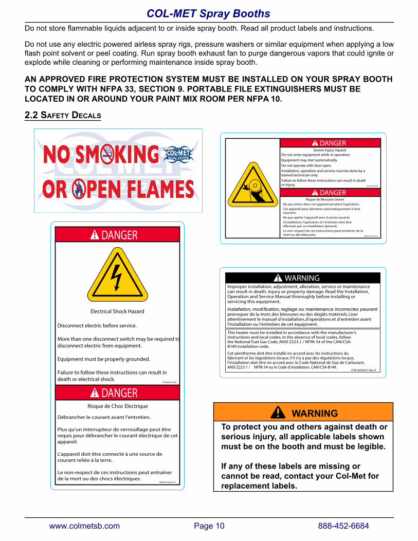
Nosmokingoropenflame inornear spraybooth.Local firecodesprohibit smoking in thevicinityof spraypainting operations.
^ WaRNINGExplosion and fire hazard.
No smoking or open flame within 50 feet of spray booth.
www.colmetsb.com Page 9 888-452-6684
COL-MET Spray Booths
Donotstoreflammableliquidsadjacenttoorinsidespraybooth.Readallproductlabelsandinstructions.
Do not use any electric powered airless spray rigs, pressure washers or similar equipment when applying a low flashpointsolventorpeelcoating.Runsprayboothexhaustfantopurgedangerousvaporsthatcouldigniteorexplode while cleaning or performing maintenance inside spray booth.
AN APPROVED FIRE PROTECTION SYSTEM MUST BE INSTALLED ON YOUR SPRAY BOOTH TO COMPLY WITH NFPA 33, SECTION 9. PORTABLE FILE EXTINGUISHERS MUST BE LOCATED IN OR AROUND YOUR PAINT MIX ROOM PER NFPA 10.
2.2 saFety decals
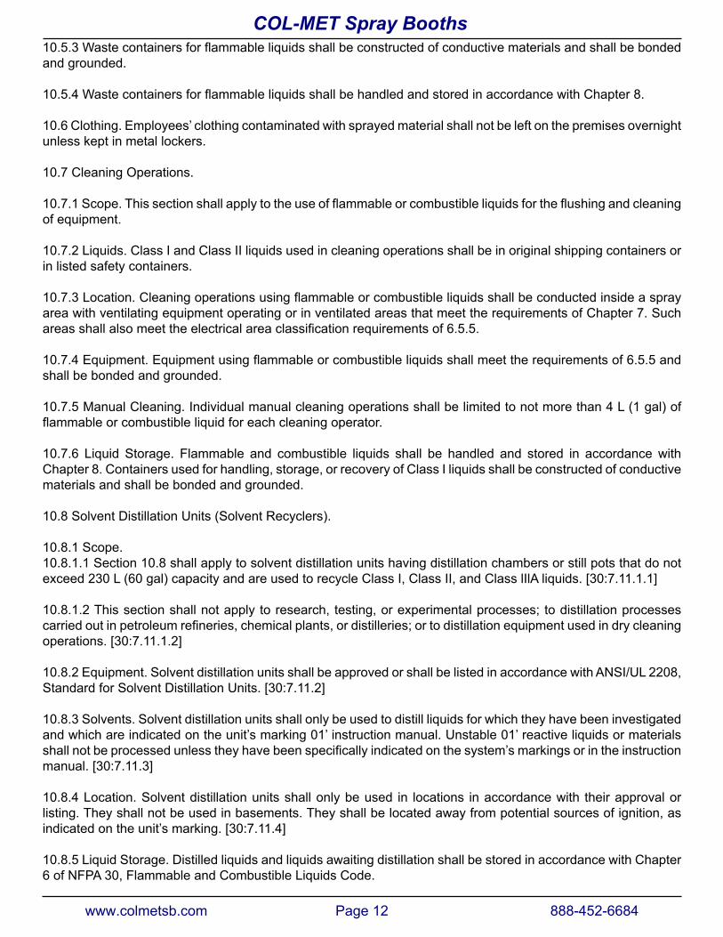
DANGER
DANGERPrinted in USA
Imprimé aux É.-U.
Electrical Shock Hazard
Risque de Choc Electrique
Disconnect electric before service.
More than one disconnect switch may be required todisconnect electric from equipment.
Equipment must be properly grounded.
Failure to follow these instructions can result indeath or electrical shock.
Débrancher le courant avant l’entretien.
Plus qu’un interrupteur de verrouillage peut êtrerequis pour débrancher le courant électrique de cetappareil.
L’appareil doit être connecté à une source decourant reliée à la terre.
Le non-respect de ces instructions peut entraînerde la mort ou des chocs électriques.
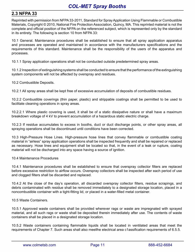
DANGER
DANGER
Severe Injury Hazard
Risque de Blessures GravesNe pas entrer dans cet appareil pendant l’opération.Cet apparell peut démarrer automatiquement à toutmoment.Ne pas opérer l’apparell avec la porte ouverte.L’installation, l’opération et l’entretien doit êtree�ectués par un installateur éprouvé.Le non-respect de ces instructions peut entraîner de lamort ou des blessures.
Do not enter equipment while in operation.Equipment may start automatically.Do not operate with door open.Installation, operation and service must be done by atrained technician only.Failure to follow these instructions can result in deathor injury. Printed in USA
Imprimé aux É.-U.
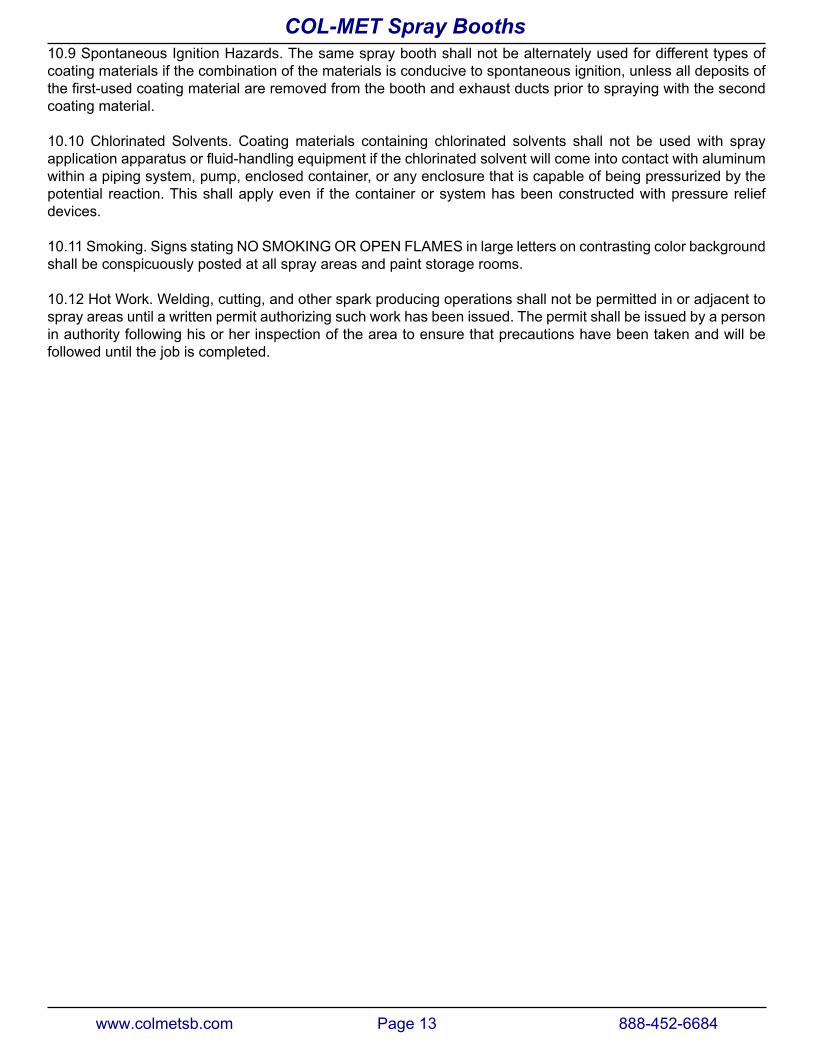
WARNINGImproper installation, adjustment, alleration, service or maintenance can result in death, injury or property damage. Read the Installation, Operation and Service Manual thoroughly before installing orservicing this equipment.
provoquer de la mort, des blessures ou des dégâts matériels. Liser attentivement le manuel d’installation, d’operations et d’entretien avant l’installation ou l’entretien de cet équipment.
This heater must be installed in accordance with the manufacturer’s instructions and local codes. In the absence of local codes, followthe National Fuel Gas Code, ANSI Z223.1 / NFPA 54 of the CAN/CSA-B149 installation code.
Cet aérotherme doit être installé en accord avec les instructions dufabricant et les régulations locaux. S’il n’y a pas des régulations locaux,l’installation doit être en accord avec le Code National de Gaz de Carburant,ANSI Z223.1 / NFPA 54 ou le Code d’installation, CAN/CSA-B149.
P/N 01010431 Rev A
^ WaRNINGTo protect you and others against death or serious injury, all applicable labels shown must be on the booth and must be legible.
If any of these labels are missing or cannot be read, contact your Col-Met for replacement labels.
www.colmetsb.com Page 10 888-452-6684
COL-MET Spray Booths
2.3 nFpa 33Reprinted with permission from NFPA 33-2011, Standard for Spray Application Using Flammable or Combustible Materials, Copyright © 2010, National Fire Protection Association, Quincy, MA. This reprinted material is not the completeandofficialpositionoftheNFPAonthereferencedsubject,whichisrepresentedonlybythestandardin its entirety. The following is section 10 from NFPA 33:
10.1 General. Maintenance procedures shall be established to ensure that all spray application apparatus and processes are operated andmaintained in accordancewith themanufacturers specifications and therequirements of this standard. Maintenance shall be the responsibility of the users of the apparatus and processes.
10.1.1 Spray application operations shall not be conducted outside predetermined spray areas.
10.1.2 Inspection of extinguishing systems shall be conducted to ensure that the performance of the extinguishing system components will not be affected by overspray and residues.
10.2 Combustible Deposits.
10.2.1 All spray areas shall be kept free of excessive accumulation of deposits of combustible residues.
10.2.2 Combustible coverings (thin paper, plastic) and strippable coatings shall be permitted to be used to facilitate cleaning operations in spray areas.
10.2.2.1 Where plastic covering is used, it shall be of a static dissipative nature or shall have a maximum breakdown voltage of 4 kV to prevent accumulation of a hazardous static electric charge.
10.2.3 If residue accumulates to excess in booths, duct or duct discharge points, or other spray areas, all spraying operations shall be discontinued until conditions have been corrected.
10.3 High-Pressure Hose Lines. High-pressure hose lines that convey flammable or combustible coatingmaterial in “airless” spray application operations shall be inspected frequently and shall be repaired or replaced as necessary. Hose lines and equipment shall be located so that, in the event of a leak or rupture, coating material will not be discharged into any space having a source of ignition.
10.4 Maintenance Procedures
10.4.1Maintenanceprocedures shall be established to ensure that overspray collector filters are replacedbeforeexcessiverestrictiontoairflowoccurs.Overspraycollectorsshallbeinspectedaftereachperiodofuseandcloggedfiltersshallbediscardedandreplaced.
10.4.2At the close of the day’s operation, all discarded overspray collector filters, residue scrapings, anddebris contaminated with residue shall be removed immediately to a designated storage location, placed in a noncombustiblecontainerwithatight-fittinglid,orplacedinawater-filledmetalcontainer.
10.5 Waste Containers.
10.5.1 Approved waste containers shall be provided wherever rags or waste are impregnated with sprayed material, and all such rags or waste shall be deposited therein immediately after use. The contents of waste containers shall be placed in a designated storage location.
10.5.2 Waste containers containing flammable liquids shall be located in ventilated areas that meet therequirementsofChapter7.Suchareasshallalsomeellheelectricalareac1assificalionrequirementsof6.5.5.
www.colmetsb.com Page 11 888-452-6684
COL-MET Spray Booths
10.5.3Wastecontainersforflammableliquidsshallbeconstructedofconductivematerialsandshallbebondedand grounded.
10.5.4WastecontainersforflammableliquidsshallbehandledandstoredinaccordancewithChapter8.
10.6 Clothing. Employees’ clothing contaminated with sprayed material shall not be left on the premises overnight unless kept in metal lockers.
10.7 Cleaning Operations.
10.7.1Scope.Thissectionshallapplytotheuseofflammableorcombustibleliquidsfortheflushingandcleaningof equipment.
10.7.2 Liquids. Class I and Class II liquids used in cleaning operations shall be in original shipping containers or in listed safety containers.
10.7.3Location.Cleaningoperationsusingflammableorcombustibleliquidsshallbeconductedinsideasprayarea with ventilating equipment operating or in ventilated areas that meet the requirements of Chapter 7. Such areasshallalsomeettheelectricalareaclassificationrequirementsof6.5.5.
10.7.4Equipment.Equipmentusingflammableorcombustibleliquidsshallmeettherequirementsof6.5.5andshall be bonded and grounded.
10.7.5 Manual Cleaning. Individual manual cleaning operations shall be limited to not more than 4 L (1 gal) of flammableorcombustibleliquidforeachcleaningoperator.
10.7.6 Liquid Storage. Flammable and combustible liquids shall be handled and stored in accordance with Chapter 8. Containers used for handling, storage, or recovery of Class I liquids shall be constructed of conductive materials and shall be bonded and grounded.
10.8 Solvent Distillation Units (Solvent Recyclers).
10.8.1 Scope.10.8.1.1 Section 10.8 shall apply to solvent distillation units having distillation chambers or still pots that do not exceed 230 L (60 gal) capacity and are used to recycle Class I, Class II, and Class lIlA liquids. [30:7.11.1.1]
10.8.1.2 This section shall not apply to research, testing, or experimental processes; to distillation processes carriedoutinpetroleumrefineries,chemicalplants,ordistilleries;ortodistillationequipmentusedindrycleaningoperations. [30:7.11.1.2]
10.8.2 Equipment. Solvent distillation units shall be approved or shall be listed in accordance with ANSI/UL 2208, Standard for Solvent Distillation Units. [30:7.11.2]
10.8.3 Solvents. Solvent distillation units shall only be used to distill liquids for which they have been investigated and which are indicated on the unit’s marking 01’ instruction manual. Unstable 01’ reactive liquids or materials shallnotbeprocessedunlesstheyhavebeenspecificallyindicatedonthesystem’smarkingsorintheinstructionmanual. [30:7.11.3]
10.8.4 Location. Solvent distillation units shall only be used in locations in accordance with their approval or listing. They shall not be used in basements. They shall be located away from potential sources of ignition, as indicated on the unit’s marking. [30:7.11.4]
10.8.5 Liquid Storage. Distilled liquids and liquids awaiting distillation shall be stored in accordance with Chapter 6 of NFPA 30, Flammable and Combustible Liquids Code.
www.colmetsb.com Page 12 888-452-6684
COL-MET Spray Booths
10.9 Spontaneous Ignition Hazards. The same spray booth shall not be alternately used for different types of coating materials if the combination of the materials is conducive to spontaneous ignition, unless all deposits of thefirst-usedcoatingmaterialareremovedfromtheboothandexhaustductspriortosprayingwiththesecondcoating material.
10.10 Chlorinated Solvents. Coating materials containing chlorinated solvents shall not be used with spray applicationapparatusorfluid-handlingequipmentifthechlorinatedsolventwillcomeintocontactwithaluminumwithin a piping system, pump, enclosed container, or any enclosure that is capable of being pressurized by the potential reaction. This shall apply even if the container or system has been constructed with pressure relief devices.
10.11 Smoking. Signs stating NO SMOKING OR OPEN FLAMES in large letters on contrasting color background shall be conspicuously posted at all spray areas and paint storage rooms.
10.12 Hot Work. Welding, cutting, and other spark producing operations shall not be permitted in or adjacent to spray areas until a written permit authorizing such work has been issued. The permit shall be issued by a person in authority following his or her inspection of the area to ensure that precautions have been taken and will be followed until the job is completed.
www.colmetsb.com Page 13 888-452-6684
COL-MET Spray Booths
3. COMPONENT DESCRIPTION
3.1 coMplIance to applIcaBle codes
This Spray Booth is designed to be in strict accordance with the National Fire Protection Association Standard Number 33, “Spray Application Using Flammable Combustible Materials. The NFPA Standard Safety Code for the Design, Construction and Ventilation of Spray Finishing Operations.” This spray booth meets or exceeds the requirements of the Occupational Safety and Health Administration (OSHA).
3.2 MaterIal specIFIcatIons
Thesprayboothpanels,filterracksandproductdoorsareconstructedof18-gaugesteel,conformingtoASTMA527 “Lock Forming Quality” and are hot dipped galvanized per ASTM A525. All structural steel conforms to ASTM A36.
3.3 general descrIptIon
The spray booth consists of four major components: paint area, exhaust fan and chamber, product doors and, in some cases, an air make-up unit. A brief description is provided for these and other related items.
3.3.1 paInt area
The paint area is the actual “booth” part of the spray booth. Parts are placed in this area, through product doors, ifsoequipped,tobepainted.Airflowsfromtheintakefiltersoftheboothtotheexhaustfilters.Theboothisconstructed of 18-gauge galvanized sheet metal panels which are bolted together. The booth exhaust is routed through the exhaust plenum at the exit of the booth. The exhaust fan then routes the exhaust out through the exhaust duct and discharges it at a point above the roof height of the building.
3.3.2 exhaust Fan and chaMBers
The booth exhaust chamber(s) is/are located as shown in the mechanical drawing package included with this manual. Exhaust gases are pumped through the exhaust duct by an electrically powered fan. The fan is made of spark resistant material and the motor is located out of the air stream. The exhaust chamber(s) operate(s) under anegativepressuretoinducetherequiredairflowthroughtheexhaustfilters.
3.3.3 product doors
Theproductdoorscanbefilteredorsolidandmaybeeitheroverheaddoors,bi-folddoors,or tri-folddoors.Some industrial spray booths have an open front in lieu of product doors.
Overhead doors are equipped with an intrinsically safe pneumatic safety edge. There are two 3-button controls to operate each door. Doors can be manually operated also.
3.3.4 door latch
Door latches secure doors in closed position and hold contact against foam rubber seal. Latches are pressure relief latches that allow doors to open in case of explosion. This feature also allows for ease of booth operator egress from spray booth by applying moderate pressure to the door from inside booth.
3.3.5 door lIMIt sWItch
Optional micro switch to indicate when a door is open on the booth. If a door is in the open position, micro switch contact is opened which breaks the circuit for the paint air solenoid.
www.colmetsb.com Page 14 888-452-6684
COL-MET Spray Booths
3.3.6 aIr Make up unIt (optIonal)Theairmakeupunit(AMU)suppliesfiltered,heatedatmosphericair.Thisunitmaybeheatedbynaturalgas,LP gas, steam coils or hot water coils. The temperature of the AMU discharge air is controlled by a thermostat. Theairflowcapacityofthefanandmotorarematchedtotheairflowcapacityofthesprayboothexhaustfans.Some air makeup units also have the capability to provide a paint cure cycle. This cycle, employed after the paint spraying operations are complete, typically involves supplying air that is heated to the paint area of the booth to decrease paint cure times.
3.4 exhaust FIlter ManoMeter
Manometerisusedtomeasurepressuredropacrossexhaustfilterstoindicatetheconditionofthefilters.
3.5 aIr solenoId valve
The function of this valve is to interrupt supply of compressed air to painting equipment under certain conditions. This is done to prevent painting from occurring when booth is not operating as designed or if any booth doors are open. Air solenoid valve is electrically interlocked with booth intake and exhaust fans. If optional switches are purchased, it is also interlocked with product doors and personnel doors. lf a fan is not operating properly, or if adoorisopenforlongerthanafewseconds,airsolenoidvalvewillshutoffflowofpressurizedairtospraygun.
Unitshouldbeinstalleddownstreamofanyregulatorsandfiltersandupstreamofpaintingequipment.Itshouldbelocatednearfittingtowhichpaintingequipmentconnectsinordertoinsurerapidlossofsupplypressure.
3.6 control panel
Paint spray booth may be equipped with an optional electrical control panel. Refer to electrical control drawings for electrical schematic. Also shown on this drawing is the wiring required for installation. No spare parts are provided with control panel. Panel and its associated wiring must be installed by a licensed electrician.
The cabinet that houses controls is either NEMA 1 or NEMA 12 rated. It is not suitable for installation in a Class I, Division II area. Refer to Chapter 6 in the NFPA 33 Standard and consult with the local authority having jurisdictionfordefinitionofthisareaforpaintspraybooth.
www.colmetsb.com Page 15 888-452-6684
COL-MET Spray Booths
4. INSTaLLaTION
4.1 general
Thismanualisaguideforinstallingavarietyofspraybooths.Theassemblydrawingsenclosedarespecificforthe booth you have purchased. This drawing is an exploded isometric drawing showing the relationship of each panel or part to the next one. A packing list of all components is provided and must be used in addition to the drawing to identify all components.
AllDAMAGESMUSTbereportedwithin24hoursofreceiptandafreightclaimfiledwiththecarrier.
4.2 prelIMInary
COL-MET booths are manufactured in accordance with NFPA 33, UFC 45 and NEC 516. However, local codes and regulations may apply to the installation and use of this product. All permits and approvals be obtained prior to installation and use of the spray booth.
1. Uncrate and inventory all spray booth components to ensure all of the parts are accounted for. Eachcomponent is numbered on the exploded view.
2. Thefloorsurfaceoftheboothmustbenon-combustiblematerialofsuchcharacterastofacilitatethesafecleaningandremovalofresidues.Thefloorsurfacemustbeflatandlevel.
3. Markthedimensionaloutlineofboothonfloor.4. Follow the step-by-step instructions provided.
4.3 plannIng ahead
1. Clearances between other work areas and combustible storage areas must be held as follows:• 3 ft. minimum clearance at all sides and sealed entry ways (i.e., door ways).• 3 ft. minimum clearance at all non-sealed entry ways (i.e., the open face of spray booth or a silhouette
openings).• 10 ft. minimum clearance must be held between the exhaust stack of the booth and the intake of another
apparatus. NFPA 33 dictates a minimum discharge clearance of 3 ft. from the nearest combustiblematerial; however, stack height requirements vary with individual states and can be up to 1½ times thebuilding’s roof height from grade.
• 10 ft. minimum clearance must be held between the intake of this booth and the exhaust of any otherapparatus.
2. Permits are not included. It is the responsibility of the end user to acquire all permits to install a booth.3. A FIRE SUPRESSION SYSTEM IS NOT INCLUDED WITH THE BOOTH BUT IT IS REQUIRED.Generally
thisissuppliedandinstalledbyalicensed local installer.4. Electrical installation must be performed by a licensed electrician familiar with national, local electrical codes
and regulations in your location.
www.colmetsb.com Page 16 888-452-6684
COL-MET Spray Booths
4.4 Booth asseMBly
Whenassemblingbooth,leaveboltsfingertightuntileachsectionisassembled.Allflangesshouldfaceoutward.Install bolts from inside so nut is outside booth. Use a drift pin to align panel holes when two or more panels are difficulttoalignbyhand.
Layoutallfloorchannelforexhaustchamberandwalls.Asyouattachwallpanelstogether,theywillalsobolttothefloorchannel.
^ WaRNINGPrevent serious injury or death.
Most booth components weigh 50-500 lbs.
use adequate lifting devices to raise, move and install booth components.
NOTICEPrevent equipment damage.
Spray booth roof will not support a person. Do not attempt to stand or walk on spray booth roof.
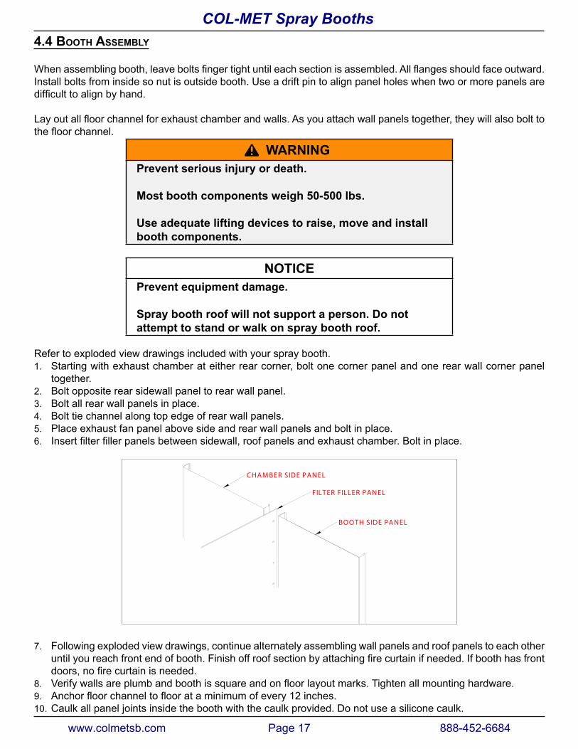
Refer to exploded view drawings included with your spray booth.1. Starting with exhaust chamber at either rear corner, bolt one corner panel and one rear wall corner panel
together. 2. Bolt opposite rear sidewall panel to rear wall panel.3. Bolt all rear wall panels in place.4. Bolt tie channel along top edge of rear wall panels.5. Place exhaust fan panel above side and rear wall panels and bolt in place.6. Insertfilterfillerpanelsbetweensidewall,roofpanelsandexhaustchamber.Boltinplace.
CHAM BER SIDE PANEL
FILTER FILLER PANEL
BOOTH SIDE PANEL
7. Following exploded view drawings, continue alternately assembling wall panels and roof panels to each otheruntilyoureachfrontendofbooth.Finishoffroofsectionbyattachingfirecurtainifneeded.Ifboothhasfrontdoors,nofirecurtainisneeded.
8. Verifywallsareplumbandboothissquareandonfloorlayoutmarks.Tightenallmountinghardware.9. Anchorfloorchanneltofloorataminimumofevery12inches.10. Caulk all panel joints inside the booth with the caulk provided. Do not use a silicone caulk.
www.colmetsb.com Page 17 888-452-6684
COL-MET Spray Booths
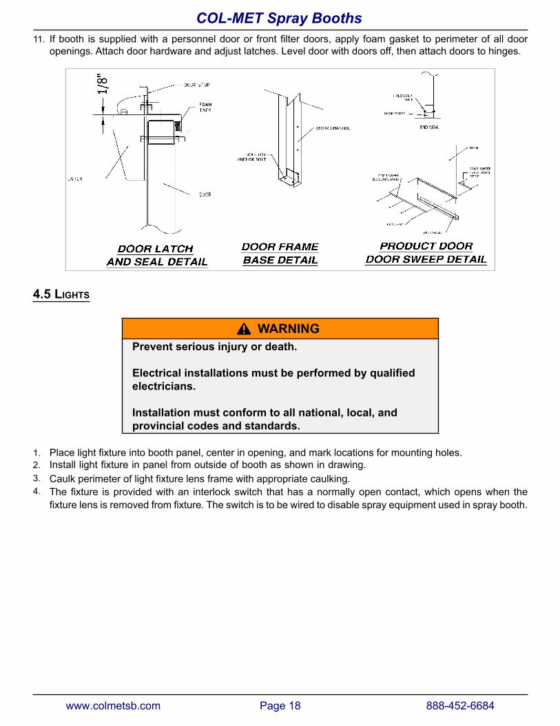
11. Ifbooth issuppliedwithapersonneldooror frontfilterdoors,apply foamgasket toperimeterofalldooropenings. Attach door hardware and adjust latches. Level door with doors off, then attach doors to hinges.
4.5 lIghts
^ WaRNINGPrevent serious injury or death.
Electrical installations must be performed by qualified electricians.
Installation must conform to all national, local, and provincial codes and standards.
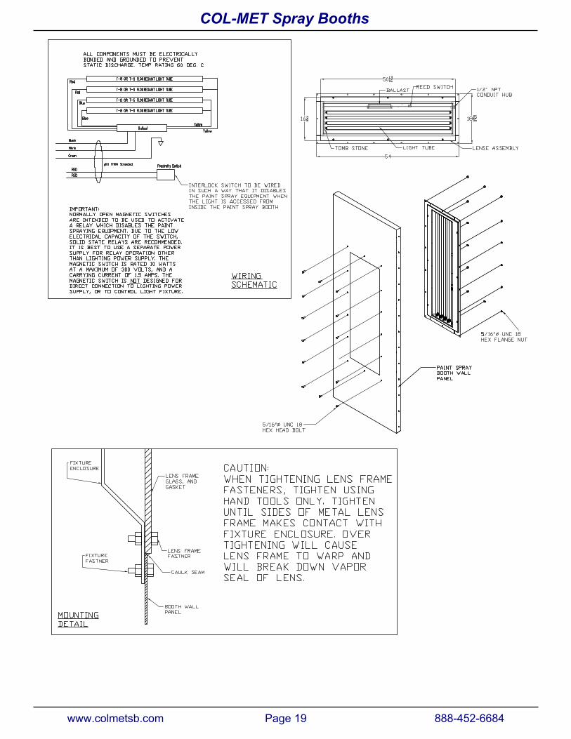
1. Placelightfixtureintoboothpanel,centerinopening,andmarklocationsformountingholes.2. Installlightfixtureinpanelfromoutsideofboothasshownindrawing.3. Caulkperimeteroflightfixturelensframewithappropriatecaulking.4. Thefixture isprovidedwithan interlockswitch thathasanormallyopencontact,whichopenswhen the
fixturelensisremovedfromfixture.Theswitchistobewiredtodisablesprayequipmentusedinspraybooth.
www.colmetsb.com Page 18 888-452-6684
COL-MET Spray Booths
www.colmetsb.com Page 19 888-452-6684
COL-MET Spray Booths
4.6 ManoMeter
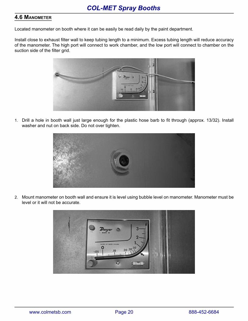
Located manometer on booth where it can be easily be read daily by the paint department.
Installclosetoexhaustfilterwalltokeeptubinglengthtoaminimum.Excesstubinglengthwillreduceaccuracyof the manometer. The high port will connect to work chamber, and the low port will connect to chamber on the suctionsideofthefiltergrid.
1. Drillahole inboothwall just largeenoughfor theplastichosebarb tofit through(approx.13/32). Installwasher and nut on back side. Do not over tighten.
2. Mount manometer on booth wall and ensure it is level using bubble level on manometer. Manometer must belevel or it will not be accurate.
www.colmetsb.com Page 20 888-452-6684
COL-MET Spray Booths
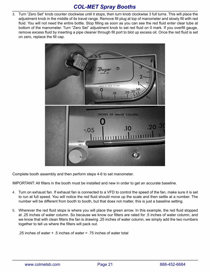
3. Turn “Zero Set” knob counter clockwise until it stops, then turn knob clockwise 3 full turns. This will place theadjustmentknobinthemiddleofitstravelrange.Removefillplugattopofmanometerandslowlyfillwithredfluid.Youwillnotneedtheentirebottle.Stopfillingassoonasyoucanseetheredfluidentercleartubeatbottomofthemanometer.Turn“ZeroSet”adjustmentknobtosetredfluidon0mark.Ifyouoverfillgauge,removeexcessfluidbyinsertingapipecleanerthroughfillporttoblotupexcessoil.Oncetheredfluidissetonzero,replacethefillcap.
Complete booth assembly and then perform steps 4-6 to set manometer.
IMPORTANT:Allfiltersintheboothmustbeinstalledandnewinordertogetanaccuratebaseline.
4. Turn on exhaust fan. If exhaust fan is connected to a VFD to control the speed of the fan, make sure it is settorunatfullspeed.Youwillnoticetheredfluidshouldmoveupthescaleandthensettleatanumber.Thenumber will be different from booth to booth, but that does not matter, this is just a baseline setting.
5. Wherevertheredfluidstopsiswhereyouwillplacethegreenarrow.Inthisexample,theredfluidstoppedat.25inchesofwatercolumn.Sobecauseweknowourfiltersareratedfor.5inchesofwatercolumn,andweknowthatwithcleanfiltersthefanisdrawing.25inchesofwatercolumn,wesimplyaddthetwonumberstogethertotelluswherethefilterswillpackout.
.25 inches of water + .5 inches of water = .75 inches of water total
www.colmetsb.com Page 21 888-452-6684
COL-MET Spray Booths
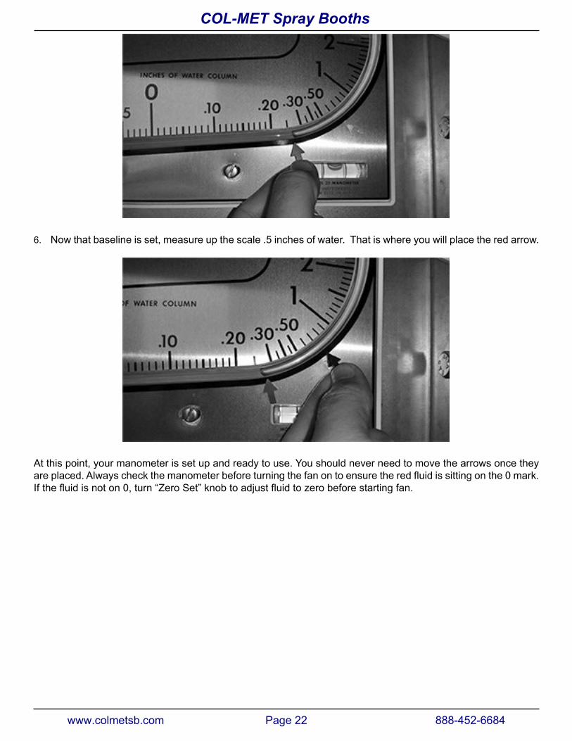
6. Now that baseline is set, measure up the scale .5 inches of water. That is where you will place the red arrow.
At this point, your manometer is set up and ready to use. You should never need to move the arrows once they areplaced.Alwayscheckthemanometerbeforeturningthefanontoensuretheredfluidissittingonthe0mark.Ifthefluidisnoton0,turn“ZeroSet”knobtoadjustfluidtozerobeforestartingfan.
www.colmetsb.com Page 22 888-452-6684
COL-MET Spray Booths
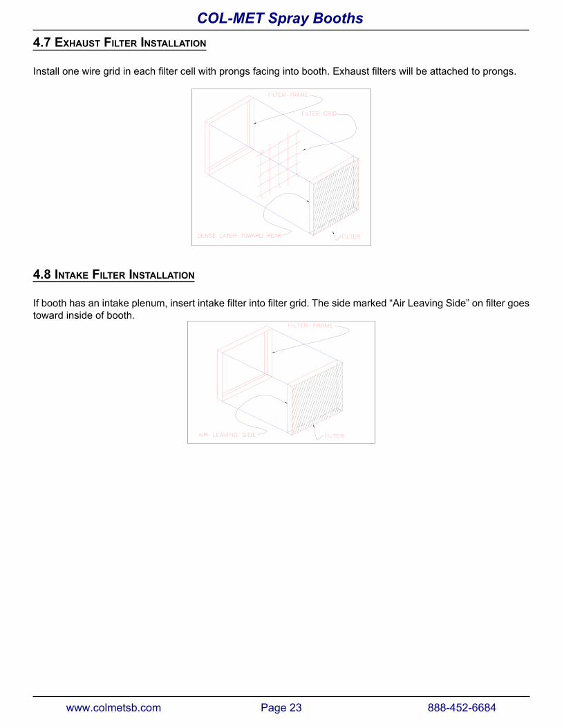
4.7 exhaust FIlter InstallatIon
Installonewiregridineachfiltercellwithprongsfacingintobooth.Exhaustfilterswillbeattachedtoprongs.
4.8 Intake FIlter InstallatIon
Ifboothhasanintakeplenum,insertintakefilterintofiltergrid.Thesidemarked“AirLeavingSide”onfiltergoestoward inside of booth.
www.colmetsb.com Page 23 888-452-6684
COL-MET Spray Booths
4.9 Motor InstallatIon
Couplings, drive belts, chains or other mounted devices must be in proper alignment, balanced and secure for safe motor operation.
4.9.1 MountIng
Thismotormustbesecurelymounted.Sufficientventilationmustbeprovidedtoinsureproperoperation.
4.9.2 Install sheaves and Fan Belts
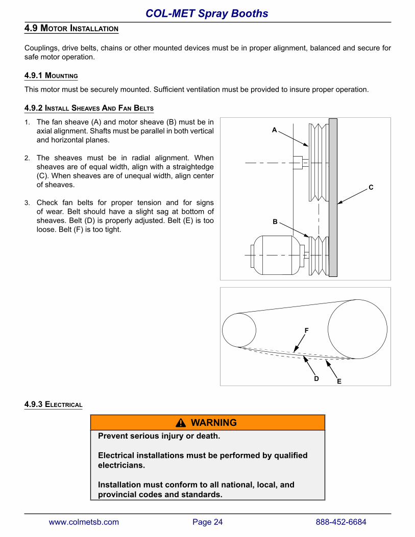
1. The fan sheave (A) and motor sheave (B) must be inaxial alignment. Shafts must be parallel in both verticaland horizontal planes.
2. The sheaves must be in radial alignment. Whensheaves are of equal width, align with a straightedge(C). When sheaves are of unequal width, align centerof sheaves.
3. Check fan belts for proper tension and for signsof wear. Belt should have a slight sag at bottom ofsheaves. Belt (D) is properly adjusted. Belt (E) is tooloose. Belt (F) is too tight.
D E
F
4.9.3 electrIcal
^ WaRNINGPrevent serious injury or death.
Electrical installations must be performed by qualified electricians.
Installation must conform to all national, local, and provincial codes and standards.
A
B
C
www.colmetsb.com Page 24 888-452-6684
COL-MET Spray Booths
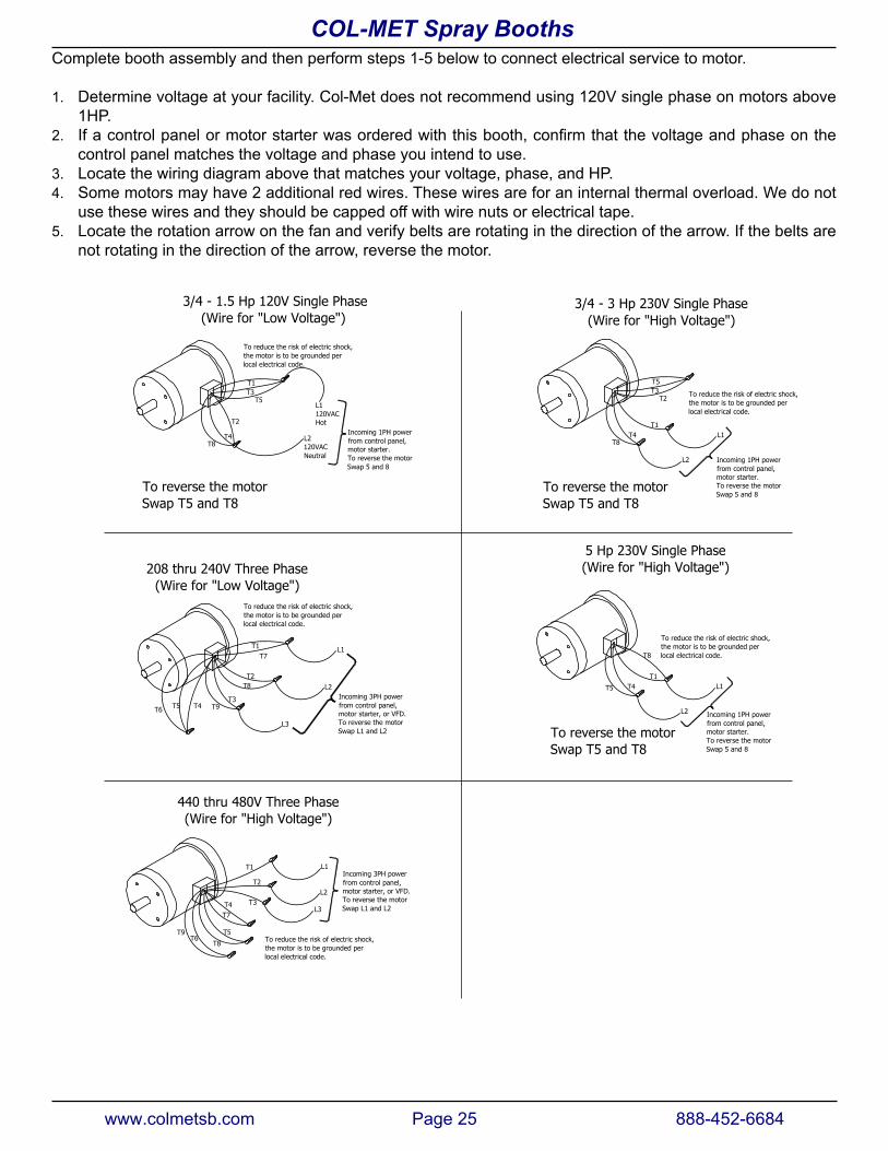
Complete booth assembly and then perform steps 1-5 below to connect electrical service to motor.
1. Determine voltage at your facility. Col-Met does not recommend using 120V single phase on motors above1HP.
2. Ifacontrolpanelormotorstarterwasorderedwiththisbooth,confirmthatthevoltageandphaseonthecontrol panel matches the voltage and phase you intend to use.
3. Locate the wiring diagram above that matches your voltage, phase, and HP.4. Some motors may have 2 additional red wires. These wires are for an internal thermal overload. We do not
use these wires and they should be capped off with wire nuts or electrical tape.5. Locate the rotation arrow on the fan and verify belts are rotating in the direction of the arrow. If the belts are
not rotating in the direction of the arrow, reverse the motor.
T1T4
T8L1
L2
T2T3T5T1
T3T5
L2120VACNeutral
L1120VACHot
T8T4
T2
3/4 - 3 Hp 230V Single Phase(Wire for "High Voltage")
5 Hp 230V Single Phase(Wire for "High Voltage")
T5
L2
L1
T8
T4T1T2
T3T9
L2
L3
T7T1
T1
T2
T3
L1
T5
T7T4
To reverse the motorSwap T5 and T8
To reverse the motorSwap T5 and T8
L1
T4T5T6
T8
L2
L3
T6T9
T8
To reduce the risk of electric shock,the motor is to be grounded perlocal electrical code.
To reverse the motorSwap T5 and T8
To reduce the risk of electric shock,the motor is to be grounded perlocal electrical code.
To reduce the risk of electric shock,the motor is to be grounded perlocal electrical code.
To reverse the motorSwap L1 and L2
Incoming 3PH powerfrom control panel,motor starter, or VFD.
To reverse the motorSwap L1 and L2
Incoming 3PH powerfrom control panel,motor starter, or VFD.
To reduce the risk of electric shock,the motor is to be grounded perlocal electrical code.
To reduce the risk of electric shock,the motor is to be grounded perlocal electrical code.
To reverse the motorSwap 5 and 8
Incoming 1PH powerfrom control panel,motor starter.
To reverse the motorSwap 5 and 8
Incoming 1PH powerfrom control panel,motor starter.
To reverse the motorSwap 5 and 8
Incoming 1PH powerfrom control panel,motor starter.
3/4 - 1.5 Hp 120V Single Phase (Wire for "Low Voltage")
208 thru 240V Three Phase(Wire for "Low Voltage")
440 thru 480V Three Phase(Wire for "High Voltage")
www.colmetsb.com Page 25 888-452-6684
COL-MET Spray Booths
4.10 tuBeaxIal Fan
^ WaRNINGfan assembly is heavy.
Fan assembly weight is approximately 50 - 200 lbs., depending on model. use and adequate lifting device to install fan assembly.
^ WaRNINGPrevent serious injury or death.
Electrical installations must be performed by qualified electricians.
Installation must conform to all national, local, and provincial codes and standards.
Thefanandmotorassemblywillbolttoexhaustroofpanel.
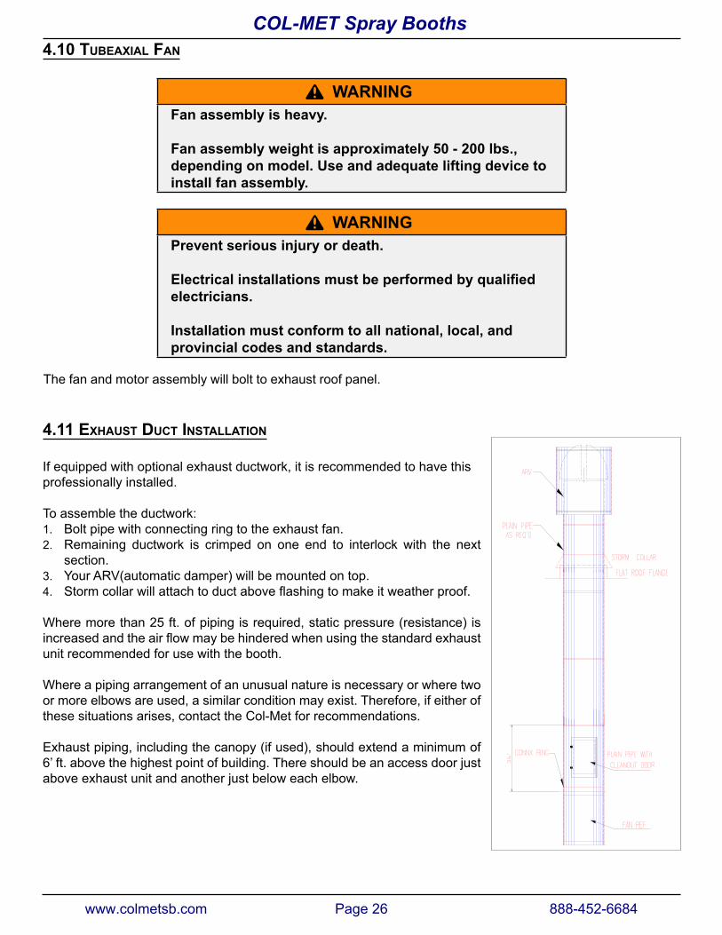
4.11 exhaust duct InstallatIon
If equipped with optional exhaust ductwork, it is recommended to have this professionally installed.
To assemble the ductwork:1. Bolt pipe with connecting ring to the exhaust fan.2. Remaining ductwork is crimped on one end to interlock with the next
section.3. Your ARV(automatic damper) will be mounted on top.4. Stormcollarwillattachtoductaboveflashingtomakeitweatherproof.
Where more than 25 ft. of piping is required, static pressure (resistance) is increasedandtheairflowmaybehinderedwhenusingthestandardexhaustunit recommended for use with the booth.
Where a piping arrangement of an unusual nature is necessary or where two or more elbows are used, a similar condition may exist. Therefore, if either of these situations arises, contact the Col-Met for recommendations.
Exhaust piping, including the canopy (if used), should extend a minimum of 6’ ft. above the highest point of building. There should be an access door just above exhaust unit and another just below each elbow.
www.colmetsb.com Page 26 888-452-6684
COL-MET Spray Booths
4.12 product door
A
A
B
B
A
A
B
B
A
A
B
B
A
A
B
B
C
C
D
D
C
C
D
D
C
C
D
D
C
C
D
D
E
E E
E
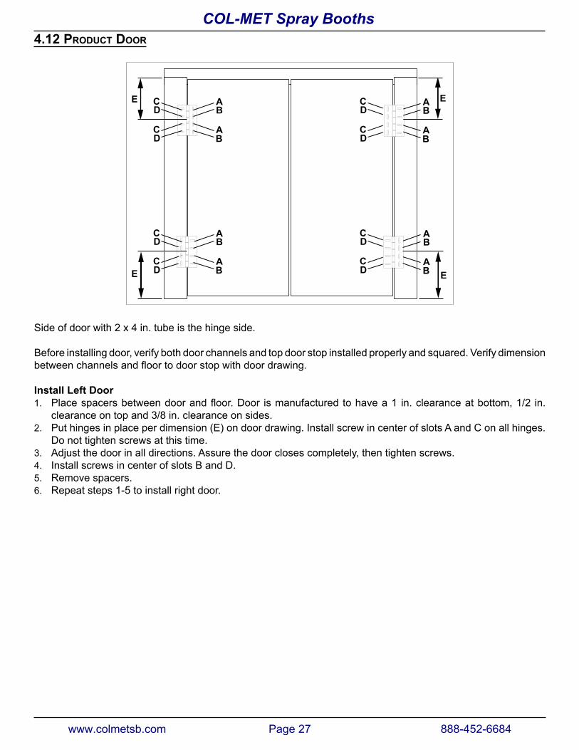
Side of door with 2 x 4 in. tube is the hinge side.
Before installing door, verify both door channels and top door stop installed properly and squared. Verify dimension betweenchannelsandfloortodoorstopwithdoordrawing.
Install Left Door1. Placespacersbetweendoorandfloor.Door ismanufacturedtohavea1 in.clearanceatbottom,1/2 in.
clearance on top and 3/8 in. clearance on sides.2. Put hinges in place per dimension (E) on door drawing. Install screw in center of slots A and C on all hinges.
Do not tighten screws at this time.3. Adjust the door in all directions. Assure the door closes completely, then tighten screws.4. Install screws in center of slots B and D.5. Remove spacers.6. Repeat steps 1-5 to install right door.
www.colmetsb.com Page 27 888-452-6684
COL-MET Spray Booths
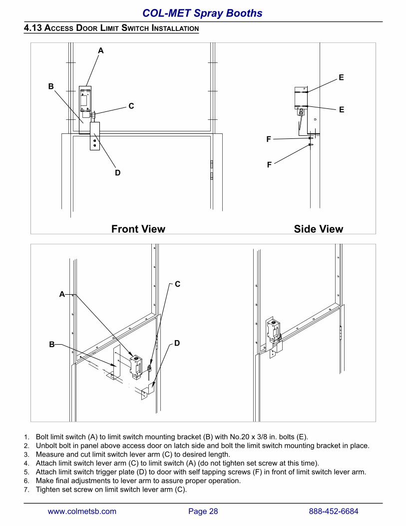
4.13 access door lIMIt sWItch InstallatIon
Front View Side View
B
A
C
D
F
F
E
E
B
AC
D
1. Bolt limit switch (A) to limit switch mounting bracket (B) with No.20 x 3/8 in. bolts (E).2. Unbolt bolt in panel above access door on latch side and bolt the limit switch mounting bracket in place.3. Measure and cut limit switch lever arm (C) to desired length.4. Attach limit switch lever arm (C) to limit switch (A) (do not tighten set screw at this time).5. Attach limit switch trigger plate (D) to door with self tapping screws (F) in front of limit switch lever arm.6. Makefinaladjustmentstoleverarmtoassureproperoperation.7. Tighten set screw on limit switch lever arm (C).
www.colmetsb.com Page 28 888-452-6684
COL-MET Spray Booths
www.colmetsb.com Page 29 888-452-6684
COL-MET Spray Booths
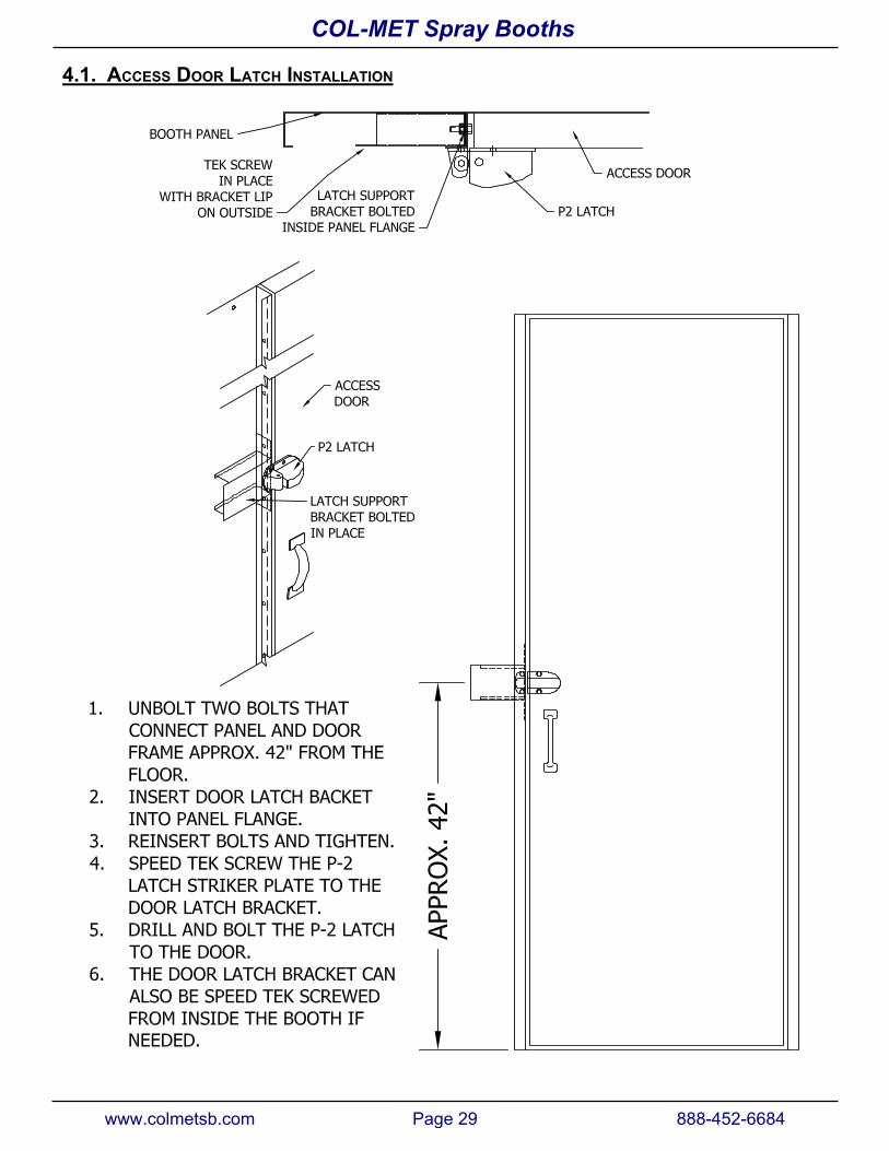
4.1. access Door lATCH InstallatIon
B
AC
D
F
E
E
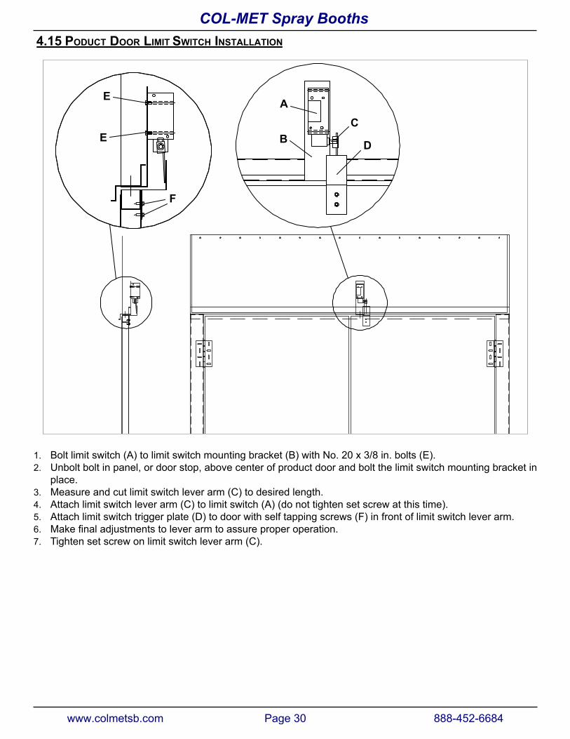
1. Bolt limit switch (A) to limit switch mounting bracket (B) with No. 20 x 3/8 in. bolts (E).2. Unbolt bolt in panel, or door stop, above center of product door and bolt the limit switch mounting bracket in
place.3. Measure and cut limit switch lever arm (C) to desired length.4. Attach limit switch lever arm (C) to limit switch (A) (do not tighten set screw at this time).5. Attach limit switch trigger plate (D) to door with self tapping screws (F) in front of limit switch lever arm.6. Makefinaladjustmentstoleverarmtoassureproperoperation.7. Tighten set screw on limit switch lever arm (C).
www.colmetsb.com Page 30 888-452-6684
COL-MET Spray Booths4.15 PODUCT Door lIMIT SWITCH InstallatIon
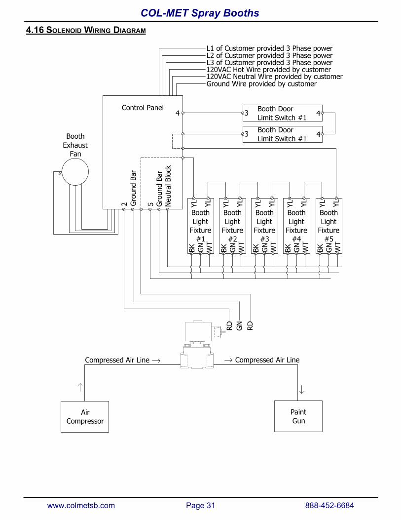
Control Panel
BoothExhaust
Fan
L1 of Customer provided 3 Phase powerL2 of Customer provided 3 Phase powerL3 of Customer provided 3 Phase power120VAC Hot Wire provided by customer120VAC Neutral Wire provided by customerGround Wire provided by customer
Booth DoorLimit Switch #1
3 4
Booth DoorLimit Switch #1
3 4
4
BoothLight
Fixture#1
BK GN
WT
YL YLBoothLight
Fixture#2
BK GN
WT
YL YL
BoothLight
Fixture#3
BK GN
WT
YL YL
BoothLight
Fixture#4
BK GN
WT
YL YL
BoothLight
Fixture#5
BK GN
WT
YL YL5 Neu
tral
Blo
ckG
roun
d Ba
r
Gro
und
Bar
RD
2
RDGN
AirCompressor
PaintGun
Compressed Air Line Compressed Air Line
www.colmetsb.com Page 31 888-452-6684
COL-MET Spray Booths4.16 SOLENOID WIRING DIAGRAM
Check the following items prior to start up:
1. Motors wired for proper voltage.2. All fans and motors turn freely.3. Lubricate all bearings.4. Checkinstallationofexhaustfanforproperairflowdirection.Generally,airflowisoutofbooth.5. Listen for excessive or unusual noise when booth is operating.6. With booth operating, open any door for 30 seconds and see if spray gun will shut down. This will verify
proper safety operation of the booth.
www.colmetsb.com Page 32 888-452-6684
COL-MET Spray Booths
4.17 CHECKLIST
5. MaINTENaNCE
^ WaRNINGPrevent serious injury or death.
Disconnect and lockout / tagout all power sources before adjusting, repairing, or cleaning booth.
^ WaRNINGPrevent serious injury or death.
Service, maintenance and adjustments must be performed by trained and qualified personnel.
^ WaRNINGBurn hazard. Do not touch hot parts.
allow to cool before servicing.
^ WaRNINGPrevent serious injury or death.
always wear personal protective equipment (PPE) specific to the job.
Read Material Safety Data Sheet for products used in spray booth.
Review and follow all safety precautions before performing any maintenance.
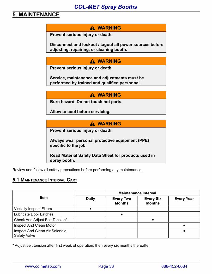
5.1 MaIntenance Interval cart
ItemMaintenance Interval
Daily Every Two Months
Every Six Months
Every year
Visually Inspect Filters ●
Lubricate Door Latches ●
Check And Adjust Belt Tension* ●
Inspect And Clean Motor ●
Inspect And Clean Air Solenoid Safety Valve
●
* Adjustbelttensionafterfirstweekofoperation,theneverysixmonthsthereafter.
www.colmetsb.com Page 33 888-452-6684
COL-MET Spray Booths
5.2 daIly5.2.1 Inspect FIlters
Visuallyinspectallfiltersfordamageanddebrisbuildup.Replacedamagedorcloggedfilters.
5.2.2 FIlter MaIntenance
^ WaRNINGPrevent serious injury or death.
always wear personal protective equipment (PPE) specific to the job.
Wearpersonalprotectiveequipmenttoprotectagainstdrypaintanddustparticleswhilehandlingfilters.
Checkmanometergaugedailyforconditionoffilters.Donotchangefilterbasedonitsappearance.
Filtersarenotnecessarilychangedatequaltimeintervals.Theusablelifeofafilterisrelatedto:
• Filter material weave.• Paint sprayed.• Distancefromguntofilter.• Paint gun type.• Amount of thinner used.• Spray pressure.
5.2.3 deterMIne FIlter condItIon
1. Thefilterconditionisacceptablewhenthemanometertubescaleisbetweenthetwoarrows.
2. Whenmanometerscaleexceedsredpointerflag,filtersmustbechanged.
3. Ifadifferentfiltermediaistobeused,manometersetupproceduremustbedoneagain.
5.3 every tWo Months5.3.1 luBrIcate door latches
Lubricate bearing pin and laminated cam with SAE 30-50 high temperature oil. Tighten set screws in handle as needed.
For use in cold areas, use SAE 10-20 high temperature oil.
Test explosion-venting feature to verify proper operation. Corrosion and/or build-up of foreign materials may affect proper operation of latches.
www.colmetsb.com Page 34 888-452-6684
COL-MET Spray Booths
5.4 every sIx Months5.4.1 check Fan Belts
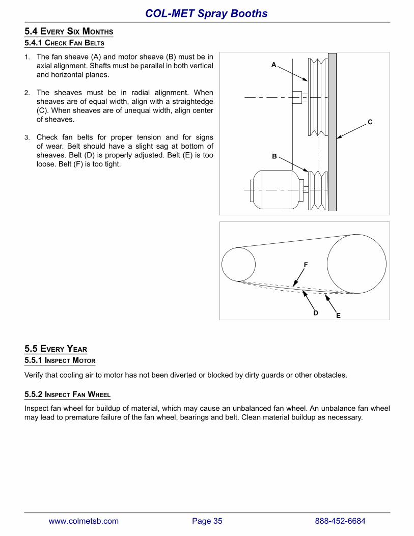
1. The fan sheave (A) and motor sheave (B) must be inaxial alignment. Shafts must be parallel in both verticaland horizontal planes.
2. The sheaves must be in radial alignment. Whensheaves are of equal width, align with a straightedge(C). When sheaves are of unequal width, align centerof sheaves.
3. Check fan belts for proper tension and for signsof wear. Belt should have a slight sag at bottom ofsheaves. Belt (D) is properly adjusted. Belt (E) is tooloose. Belt (F) is too tight.
D E
F
5.5 every year5.5.1 Inspect Motor
Verify that cooling air to motor has not been diverted or blocked by dirty guards or other obstacles.
5.5.2 Inspect Fan Wheel
Inspect fan wheel for buildup of material, which may cause an unbalanced fan wheel. An unbalance fan wheel may lead to premature failure of the fan wheel, bearings and belt. Clean material buildup as necessary.
A
B
C
www.colmetsb.com Page 35 888-452-6684
COL-MET Spray Booths
5.5.3 Inspect and clean aIr solenoId valve
The function of this valve is to interrupt the supply of compressed air to the painting equipment when the booth is not operating as designed or if any booth doors are open.
^ WaRNINGPrevent serious injury.
Turn off electrical power, depressurize valve, and vent fluid to a safe area before servicing valve.
The time between cleanings varies depending on the medium and service conditions. If voltage to coil is correct, sluggishvalveoperation,excessivenoiseorleakageindicatesthatcleaningisrequired.Closestrainerorfilterwhen cleaning valve. Thoroughly clean all parts. If parts are worn or damaged, install a complete rebuild kit.
Follow instructions included with rebuild kit.
www.colmetsb.com Page 36 888-452-6684
COL-MET Spray Booths
6 WaRRaNTy
Col-Met Spray Booths has a full one year Warranty on all parts and materials. This warranty does not extend to include labor costs for the replacement of parts or materials covered under warranty.
If a part is believed defective, please notify our Customer Service Department. A replacement item shall be shipped and regular freight shall be paid by Col-Met.
If Col-Met requires the defective part to be returned, appropriate return freight costs shall be paid by Col-Met.
IMPORTANT:Beforereturningthedefectivepart(s),youmustfirstgetanRGA(ReturnofGoodsAuthorization)from our Customer Service Department. A copy of the RGA document MUST be included with the returned item(s).
The Seller warrants to Buyer that the equipment mentioned herein shall be free from defects of materials or workmanship under normal use and maintenance for a period of one (1) year from date of shipment. The liability of Seller under this warranty shall be limited to the repair or replacement, at Seller’s option, of any part or component which may prove to be defective under normal use, service and maintenance after Seller, in its sole discretion, determines same to be defective. Said warranty is conditioned upon Buyer giving Seller immediate written notice of an alleged defect and refraining from the attempted repair of alleged defects without prior written consent of Seller. The Seller makes no warranty whatsoever with respect to accessories or components not supplied by Seller. For any components purchased by Seller for use on or in conjunction with the equipment which is the subject of this contract, the Seller extends to the Buyer only the same warranty granted to Seller by the component vendor or manufacturer.
THIS LIMITED WARRANTY IS EXCLUSIVE AND IS IN LIEU OF ANY OTHER WARRANTIES (EXPRESS OR IMPLIED) INCLUDING WARRANTY OF MERCHANTABILITY OR WARRANTY OF FITNESS FOR PARTICULAR PURPOSE AND OF ANY NON-CONTRACTUAL LIABILITIES INCLUDING PRODUCT LIABILITIES BASED ON NEGLIGENCE OR STRICT LIABILITY. EVERY FORM OF LIABILITY FOR DIRECT, SPECIAL, OR CONSEQUENTIAL DAMAGES OR LOSS IS EXPRESSLY EXCLUDED AND DENIED. IN NO CASE SHALL COL-MET SPRAY BOOTHS LIABILITY ON THIS WARRANTY EXCEED THE AMOUNT OF THE PURCHASE PRICE.
The performance and safety of the equipment mentioned herein is contingent upon proper installation, the use of suitable process materials and operation and maintenance by properly trained personnel.
During the warranty period, Col-Met Spray Booths will repair or replace, free of charge, any parts that Col-Met SprayBoothshasverifiedtobedefectiveinmaterialsorworkmanship.Ifinspectionoftheequipmentdoesnotdisclose any defect in workmanship of material, repairs will be made at a reasonable charge, which will include the costs of labor, materials and transportation.
6.1 returnIng IteMs For credIt
Col-Met Spray Booths will take back any standard stocked items returned and issue a credit, less a 15% handling and restocking fee. Customer is responsible for all Freight Charges and the item MUST be returned in its original condition. If the item is damaged in transit you will not receive credit. Col-Met will mark the Bill of Lading “Damaged” and send you pictures of the damaged item. For custom or non-stock special order items you must contact our Customer Service Department to determine is the item may be returned. Any restocking charges shall be determined on a case by case basis.
www.colmetsb.com Page 37 888-452-6684
COL-MET Spray Booths
If an item needs to be returned, Col-Met will issue you an RGA (Return Goods Authorization) form. Please ensure that a copy is sent back with returned item(s). Without an RGA the product may be lost or returned to stock with no credit issued. Please note that in some cases the freight may be more than the item is worth when credit is received.
6.2 Back charges For MaterIal and laBor
Col-Met Spray Booths shall not be held responsible for any Back-Charges incurred for materials or labor without prior written consent.
Should a problem arise, please notify Col-Met immediately. Once the issue is investigated, should costs be incurred,anamountshallbeagreedonbybothpartiesbefore-hand.DoNOTattemptmodificationsorrepairswithout prior consent as this may void further warranty repairs or credit. Col-Met will not accept back-charges associated with late delivery.
Please address warranty repairs to:
Col-Met Spray Booths1635 Innovation DriveRockwall, TX 75032Attention: Customer Service
For all electrical and gas control service issues please direct to:
Col-Met Spray Booths1635 Innovation DriveRockwall, TX 75032Attention: Controls Engineering Manager
www.colmetsb.com Page 38 888-452-6684
COL-MET Spray Booths
www.colmetsb.com Page 39 888-452-6684
COL-MET Spray Booths