installation manual · pdf filebattery 4 detector circuits 4 l+ as latch line 4 l+ as id-...
TRANSCRIPT

INSTALLATIONMANUAL
SECURIT 800L+ CONTROL PANELWith additional options

1
CONTENTSWarnings 2Standards 2Warranty Statement 2Product Description 2Available Parts 2Intended use 2Specifications 3
Processor Version 3Power Supply 3Keypads 3General 3Factory Defaults 3
Installation 4Mounting 4Wiring 4Battery 4Detector Circuits 4L+ as Latch Line 4L+ as ID- (detector reset) 5Sounders 5Strobe 5Keyswitch Connections 5Aux DC power 5PCB Layout 5Mounting & wiring Keypads 6
Powering Up 6Entering Engineering Mode 7Programming 7
Chime 7Sound options 7Exit Time 7Entry Time 7Sounder Duration 8Night & Hone Set Exit Time 8
Circuit Programming 9Zone Selections 9
Extended Programming 9Home Set Zone Selection 9/10Engineer Access Code 10Engineer Log Review 10Engineer Test Options 10Restoring Default Programming 11Restoring Default Codes 11Glossary Of Terms 11/12Information Table 13Sounder Wiring Chart 13Fault Finding 14Wiring Diagram 15

2
WARNINGSProlonged short circuit of any supply can cause damage to the unit. Take the necessaryprecautions in not allowing liquids to spill on or into the unit.
STANDARDSThis unit conforms to EMC directive 89/336/EEC & LVD 73/23/EEC. This unit has beentested and has proven to meet all current emission and immunity regulations as set out bythe EU. This unit conforms to the requirements of BS4737 part 1 1986 which relates tosecurity control equipment.
WARRANTY STATEMENTThis product is covered by the IntelliSense warranty in force as of the purchase date, a copymay be obtained from the address at the end of this document.
PRODUCT DESCRIPTIONThe Securit 800L is an 8 zone programmable microprocessor control panel using state ofthe art technology and manufacturing techniques. The panel has many advanced featuresthat can only be found in more expensive control panels. These features include two usercodes, Chime, Fire, and Keypad PA. There are many options in the programming functionsto allow the control panel to be versatile and user friendly. This panel is the ideal choice forresidential or light commercial installations.
AVAILABLE PARTSA selection of spares and extras are available. These are:-
• Remote Keypad - giving full control over the control panel.
• Spare PCB - for replacement in the event of failure.
These can be obtained from your original place of purchase.
INTENDED USEThis panel is designed to be used in residential and light commercial applications such ashomes, small shops etc.

3
SPECIFICATIONS SPECIFICATION FOR SOFTWARE REVISION NUMBER V3.0The software revision number is located on the top of the main processor
Power SupplyMains Supply Voltage 230 V AC NominalPSU output voltage 13.7 V NominalMaximum output current 1 A (total)Aux. current 500 mA Max.Battery Fuse 1 A (20 mm)Panel Quiescent 40 mA
KeypadsSupply Voltage 13.7 VQuiescent Current 20 mAActive 45 mAMaximum number allowed 6
General Normal operating temperature 0°C to 40°C
Humidity 10 to 90% R.H. non condensingDimensions W 263 mm H 223 mm D 82 mmControl Panel Weight 2.7 kg Excluding Battery
Standby Battery 7.0 Ah 12 V Rechargeable Lead AcidStandby Time (load dependant) 24 hrs with 2.8 Ahr nom.
60 hrs with 7.0 Ahr nom.Based on panel, Keypad, & 2 pir’s40+20+25+25mA = 110mA Quiescent
Cable RunsZone/circuits 100m max with 50mA load.Sounder 50m max with 7/0.2
100m max with 16/0.2 or 2 x 7/0.2
Factory DefaultsUser/customer Code 1 1234User/customer Code 2 Disabled (0000)Engineer Code 7890Circuit 1 Entry Circuit. (Fixed)Circuit 2 Alarm Circuit isolated in Night set.Circuit 3 Alarm Circuit.Circuit 4 Alarm Circuit.Circuit 5 Alarm Circuit.Circuit 6 Alarm Circuit.Circuit 7 Alarm Circuit.Circuit 8 P.A (Personal Attack)Full Set Exit Time 30 SecondsNight set Exit Time 15 SecondsEntry time 30 SecondsSounder Ring Time 15 MinutesChimes DisabledProgrammable options Non selected
PROCESSORVERSION
POWERSUPPLY
KEYPADS
GENERAL
FACTORYDEFAULTS

4
INSTALLATIONLocate the control panel out of sight, such as in a hall, under stairs or in acupboard where connection is easy and the detector zone and mainscables can be concealed. Avoid areas subject to high temperatures orhumidity such as next to a boiler, airing cupboard or conservatory.
Mounting
1. Remove the lid screws and remove lid.2. Remove the PCB or keypad packaging.3. Place the panel in the selected position and mark the three fixing holes.4. Mount the Panel securely using all three mounting hole positions.5. Attach the tamper spring and mount the PCB onto the support pillars.
WIRING THE CONTROL PANEL
ELECTRICAL SAFETY NOTICE.
THIS PRODUCT MUST BE EARTHEDThis Power Supply must be permanently connected to the mains supplyin accordance with current IEE wiring regulation. A 3 amp fused spur,installed by a qualified electrician, is strongly recommended.
Any fault which could be mains related must be diagnosed andcorrected by a qualified electrician to ensure continued safe operation.
CAUTION: Under certain circumstances the transformer metalworkcan reach 70°C. this is normal and within prescribed limits.
Battery connection.
Maximum battery size 12V 7.0Ah
This panel requires a standby battery to be fitted to provide power in theevent of mains failure. A valve regulated lead acid battery must be used.
Detector circuits
Connections are provided for up to eight detector circuits of which normallyclosed detection devices must be used. A common tamper loop is providedfor all detection devices marked as 24 HR Tamper. One or more devicesmay be connected to each alarm circuit. These should be connected in aseries configuration. These circuit connections are located to the bottomright of the PCB (see diagram B).
PIR Latch Line (L+)
In the event of two or more detectors (motion sensors or glassbreakdetectors) being fitted to any single zone, latching detectors should beused. The 'L+' connection provides this function. It is low (0 V) whenunset and high (12 V) when set. It should be connected to the appropriateSET or LATCH terminal in your detector. See glossary for explanation.
INSTALLATIONPROCEDURES
MOUNTINGPROCEDURE
MAINS POWERWARNING
BATTERYSPECIFICATION
DETECTORCIRCUITS
LATCH LINEDESCRIPTION

5
Detector reset (L+ when programmed for ID)
Some detectors require the removal of power to reset (e.g. Viper Plus® orSmoke detectors). The L+ terminal can be programmed to be used as an 'ID'output using option 7-4. The L+ terminal should then be used as the negativesupply for these devices. The positive supply should be taken from the AUX +.
Internal Sounders, Speakers, Strobe and Keyswitch Wiring.
DIAGRAM A
A maximum of two 16 ohm speakers may befitted in parallel.
External Sounder & Strobe.
Diagram A shows the connection for external sounder and strobe. Please notesounder trigger is applied negative. (Negative ring).
ST- Strobe switched negative trigger.S - Sounder switched negative trigger+ Sounder hold off/strobe positive supply.- Sounder hold off supply & sounder tamper feed (negative)-R Sounder tamper return. (negative)
AUX DC - Detector power.
The auxiliary power is provided from connections marked 'AUX'. This is toprovide the 12 V supply for detectors e.g. movement or glassbreak detectors.The auxiliary power output is rated at 500 mA max. (12 VDC nominal). Seediagram B
DIAGRAM B
DETECTORRESET
SOUNDERS
EXTERNALDEVICES
AUXILIARYPOWER
PCB BOARDLAYOUT
Keyswitch Connections
Open = ON Closed = OFF
Z8 only
OFF
ON
6
MOUNTING A REMOTE KEYPAD
1. Choose the keypad location and then mark the holes for mounting.2. Make sure the cable is run through the backbox.3. Screw the backbox in the selected position making sure it is not twisted.
WIRING A REMOTE KEYPAD
Use 6 core cable for connection of all remote keypads.
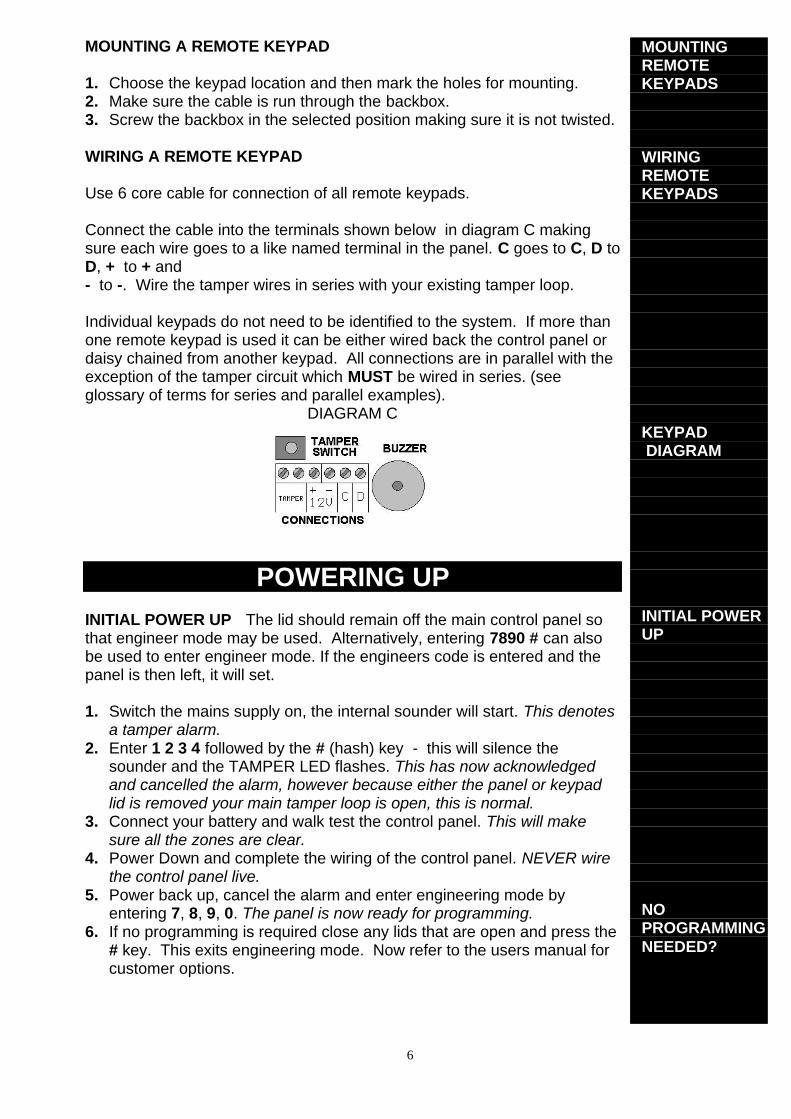
Connect the cable into the terminals shown below in diagram C makingsure each wire goes to a like named terminal in the panel. C goes to C, D toD, + to + and- to -. Wire the tamper wires in series with your existing tamper loop.
Individual keypads do not need to be identified to the system. If more thanone remote keypad is used it can be either wired back the control panel ordaisy chained from another keypad. All connections are in parallel with theexception of the tamper circuit which MUST be wired in series. (seeglossary of terms for series and parallel examples).
DIAGRAM C
POWERING UPINITIAL POWER UP The lid should remain off the main control panel sothat engineer mode may be used. Alternatively, entering 7890 # can alsobe used to enter engineer mode. If the engineers code is entered and thepanel is then left, it will set.
1. Switch the mains supply on, the internal sounder will start. This denotesa tamper alarm.
2. Enter 1 2 3 4 followed by the # (hash) key - this will silence thesounder and the TAMPER LED flashes. This has now acknowledgedand cancelled the alarm, however because either the panel or keypadlid is removed your main tamper loop is open, this is normal.
3. Connect your battery and walk test the control panel. This will makesure all the zones are clear.
4. Power Down and complete the wiring of the control panel. NEVER wirethe control panel live.
5. Power back up, cancel the alarm and enter engineering mode byentering 7, 8, 9, 0. The panel is now ready for programming.
6. If no programming is required close any lids that are open and press the# key. This exits engineering mode. Now refer to the users manual forcustomer options.
MOUNTINGREMOTEKEYPADS
WIRINGREMOTEKEYPADS
KEYPAD DIAGRAM
INITIAL POWERUP
NOPROGRAMMINGNEEDED?
7
To enter engineering mode, enter the engineering code and then press the #(HASH) key. This forces the panel into engineering mode Note: If leftunattended for approximately 60 seconds it will revert to day mode.
To exit engineering mode, confirm any options you have selected with the *(STAR) key, then close ALL tamper circuits and wait for approximately 60seconds after which the panel will automatically exit engineering mode orpressing the # (HASH) key will manually exit engineering.If you need to stay in engineering for longer unattended periods, once inengineering mode open a tamper circuit. The easiest way to do this is toremove the lid of the panel or keypad.
PROGRAMMING
To exit all options press * to confirm the selection The accept tone willsound.
CHIME 2 1 (Range - any alarm zone)
Enter 2-1. Enter the keys corresponding to the zone(s) required to chime. Onexit from engineer mode zones selected will be set to chime, the customer maydisable chime only on zones programmed with this option (see user manual).If no zones are selected the user will not be able to access their chime optionand an error tone will be heard.
SOUND OPTIONS 2 2
Enter 1 Disable exit / entry sounds in part and home setEnter 2 Disable accept / error sounds in part and home set
EXIT TIME 3 0 (Range 10-90 Seconds.)
Enter 3-0. A new time can be programmed by entering a key from the table.
Enter 1 10 Seconds. Led 1 on.Enter 2 15 Seconds. Led 2 on.Enter 3 30 Seconds. Led 3 on. (Factory default)Enter 4 45 Seconds. Led 4 on.Enter 5 60 Seconds. Led 5 on.Enter 6 90 Seconds. Led 6 on.
ENTRY TIME 3-1 (Range 10-90 seconds)
Enter 3-1. A new time can be programmed by entering a key from the table.
Enter 1 10 Seconds. Led 1 on.Enter 2 15 Seconds. Led 2 on.Enter 3 30 Seconds. Led 3 on. (Factory default)Enter 4 45 Seconds. Led 4 on.Enter 5 60 Seconds. Led 5 on.Enter 6 90 Seconds. Led 6 on.
ENTERENGINEERINGMODE
EXITENGINEERINGMODE
STAY INENGINEERINGMODE
PROGRAMMING
GENERAL
CHIME
SOUNDOPTIONS
TIMERSEXIT TIME
ENTRY TIME

8
SOUNDER DURATION (sounder ring time) 3-2 (Range 3-20 minutes)
Enter 3-2. A new time can be programmed by entering a key fromthe table.
Enter 1 3 minutes. Led 1 on.Enter 2 4 minutes. Led 2 on.Enter 3 5 minutes. Led 3 on.Enter 4 10 minutes. Led 4 on.Enter 5 15 minutes. Led 5 on. (Factory default)Enter 6 20 minutes. Led 6 on.
NIGHT SET / HOME SET EXIT TIME 3-3 (Range 0-90 seconds)
Enter 3-3. A new time may be programmed by entering a key from thetable.
Enter 0 0 Seconds. All LED's off ( Instant ).Enter 1 10 Seconds. Led 1 on.Enter 2 15 Seconds. Led 2 on. (Factory default)Enter 3 30 Seconds. Led 3 on.Enter 4 45 Seconds. Led 4 on.Enter 5 60 Seconds. Led 5 on.Enter 6 90 Seconds. Led 6 on.
NOTE: If extension speakers are fitted then the exit sounder volume forNight or Home set can be altered by the control on the PCB markedVOLUME
Option Option Results from choosing option no.Code Description 0 1 2 3 4 5 63-0 Exit Time (secs) 10 15 30 45 60 903-1 Entry Time (secs) 10 15 30 45 60 903-2 Sounder Duration (mins) 3 4 5 10 15 203-3 Night / Home Exit (secs) 0 10 15 30 45 60 90
ExamplesChange the FULL set exit time to 60 secondsENTER THIS 3-0 5 *
Description Choose full set Select 60 seconds Confirm selection
Change the Sounder duration to 3 minutesENTER THIS 3-2 1 *
Description Choose sounder Select 3 minutes Confirm selection
Change the ENTRY time to 45 secondsENTER THIS 3-1 4 *
Description Choose entry Select 45 seconds Confirm selection
SOUNDERDURATION
NIGHT / HOMESET EXIT TIMER
SUMMARY

9
CIRCUIT PROGRAMMING 4 (Range 2-7)
Circuits 2 - 7 can be reprogrammed to suit your requirements. Circuit 1 isfixed as a Final exit circuit. Circuit 8 has limited options.
ENTER PROGRAM ZONE ENTER PROGRAM ZONE4 - 2 2 4 - 6 64 - 3 3 4 - 7 74 - 4 4 4 - 8 84 - 5 5
Select the circuit you wish to alter, it may then be programmed by entering onekey from the following table.
N/S = Night Set
Option no. Zones 2-7 Zone 81 Alarm Alarm2 Alarm with walk through Fire3 Alarm & Isolate in Night Set PA4 Alarm, Walk through & Isolate in N/S Keyswitch5 Alarm, Walk through & N/S Entry6 Fire7 Entry Route8 P.A
SEE GLOSSARY OF TERMS (p.11) FOR DESCRIPTIONS OF ZONE TYPES etc.
To program zone 3 as an “Entry Route” enter - 4 3 7 *To program zone 8 as a “Keyswitch” enter - 4 8 4 *Momentary keyswitch Turn and hold for 0.5 sec = FULL SET
Turn and hold for 2.3 sec = PART SET
EXTENDED PROGRAMMING OPTIONS 7 (Range 1-8)
Enter 7 - 1 Disables sounder & strobe in night set.Enter 7 - 2 Keypress tamper alarm (after 16 incorrect keypresses)Enter 7 - 3 Full set door sense setting.Enter 7 - 4 Convert L+ to ID- output.Enter 7 - 5 Allow Manual Isolation of Zone 1 (Entry/Exit) In Night Set.Enter 7 - 6 Remote Keypad PA Enable (Operated by * & # ).Enter 7 - 7 L+ signals first to alarm.Enter 7 - 8 Inhibit strobe in Night and Home Set and testing. (For
speech dialler connection)
HOME SET ZONE SELECTION 8 (Range 1-8 N/A if Fire or PA)
The Home Set feature enables parts of the premises to be alarm protectedwhile other parts are occupied. This is similar to Night Set except that anExit/Entry route is not required as part of the Setting or Unsetting procedure.
In programming mode press 8 to select Home Set zone selection mode, thenby pressing the keys 1-8 on the keypad you will select which zones you wantISOLATED during home set. As a key is pressed, its relevant LED on thedisplay will toggle on or off. Any LED’s that are ON will be ISOLATED duringhome set and any that are off will remain ACTIVE.
CIRCUITPROGRAMMING
ZONESELECTIONS
EXTENDEDPROGRAMMING
HOME SETZONESELECTION

10
ENGINEER ACCESS CODE 1-1
The engineer access code is programmed to 7890 by default. To changethis code (while in engineering mode):
1. Enter 1-1. LEDs 1, 2, 3 and 4 will illuminate.2. Enter the new 4 digit code. After each keypress one LED will go out.
The speaker will emit an accept tone if the new code is accepted.If the speaker emits an error tone, then your new chosen code is invalid.This could be due to a conflict with another code. At this time your oldaccess code is still valid. Repeat the procedure using a different code.
ENGINEER EVENT LOG REVIEW 5 (Choices of set & unset)
The Panel stores the last set and unset states and the last alarm event. Thelog is arranged into SET and UNSET events. Log entries indicate the firstand subsequent alarms and also isolated circuits. First to alarm is shownby the LED being ON continuously. Subsequent alarms are shown by theLED(s) flashing and isolated circuits by the LED(s) pulsing slowly. Thebuzzer sounds whilst reviewing the SET logs and is silent while reviewingthe UNSET logs.
To view the engineers log press the 5 key from the program mode. The logstarts viewing DAY 1 SET. View the remaining logs by pressing therelevant key 2 for 2nd, 3 for 3rd and so on up to 9. Press the 0 key to get thelast alarm condition.
The # key alternates between SET and UNSET logs and can be used atany time.
ENGINEER TEST OPTIONS 6 (Range 0-5)
To conduct testing activities first press the 6 key from within engineeringmode and then one of the option below.
Enter 0 Internal buzzer ( entry exit sound etc. )Enter 1 Internal Sounder ( Alarm sounds from speaker / keypad )Enter 2 External SounderEnter 3 External StrobeEnter 4 L+ Terminal( even if programmed as ID- )Enter 5 FULL LOAD ( Everything enabled )
ENGINEERACCESS CODE
ENGINEERLOG REVIEW
ENGINEERTEST OPTIONS

11
FACTORY PROGRAMMING DEFAULTS 9-9
Restoring programming Defaults.
Enter 9-9, The sounder will give a rapid pipping sound, wait for 5 seconds, anaccept tone sounds, the factory programming defaults are restored. The userand engineer codes do not change.Note: If any keys are pressed this procedure will be aborted.
Restoring Code Defaults1. Place the small link supplied with the spare fuses, on the memory link.
This is positioned above the volume control and is labelled “MemoryDefault”.
2. Remove the mains and battery supply.3. Wait a few seconds then re-connect the battery and then the mains
Refer to page 6 regarding initial power up. The speaker will emit the accepttone and the factory user code defaults will be restored.
4. Be sure to remove the link .
Locking the Engineer Code
Use this option with care. You can lock the engineer code to preventunauthorised alteration. To enable the engineer code must end in 9. If theengineer code is lost, it will not be possible to enter engineer mode, the PCBwill need to be replaced. This is considered to be a “Chargeable repair”.
GLOSSARY OF TERMSFULL SETThis is a setting method normally used when leaving the premises. Full systemarmed.
NIGHT SETThis is a setting method normally used when going to bed
HOME SETThis is a setting method normally used for high security protection whilst stillinside the premises. For example an antiques cabinet etc.
ALARMThis is a zone that will trigger the panel when activated, providing the panel isset.
WALK THROUGHThis zone will be disabled during an entry period.
ISOLATE IN NIGHT SETThis simply means the zone will be disabled when the panel is NIGHT SET. Forexample downstairs
NIGHT SET ENTRYWhen the panel is NIGHT SET the zone, when activated, will start the entrytimer but if the panel is FULL SET then this zone will acts as an ALARM zone.
FACTORYDEFAULTS
RESTOREDEFAULTPROGRAMMING
RESTOREDEFAULTCODES
GLOSSARY OFTERMS

12
ENTRY CIRCUITThis will start the entry timer when activated providing the panel is set.
FIRE (for use with smoke detectors etc.)A zone that when activated emits an ascending sound from any internal speakers.If the panel is set, external sirens and strobes will also sound but in an unset statethe external sounders will pulse every two seconds.
TAMPERThis is a loop that should run through every device on your system. If broken, ittriggers the internal speakers. If the panel is set, the external sounders andstrobes will also trigger. The tamper LED is shown on the keypad as TPR.
CHIMEChime is similar to a doorbell. This can be used to alert a user to a certain zonebeing triggered during the day.
DOOR SENSE SETTINGThis allows you to have a variable FULL SET EXIT TIME. You can program theEXIT time to maximum and when you full set the system, the exit time will drop to8 seconds as soon as the EXIT door has closed thus avoiding the preset exit time.
KEYSWITCHThis allows the panel to be Full set, Part set, Unset and Reset via zone 8.
Note: To use the keyswitch for setting and unsetting, connect to zone 8 andprogram that zone to be KEYSWITCH. To set the panel, turn the key so that thecontacts are open, hold in this position for about a second for full set or about 2seconds for night set. To unset the panel, turn and hold for about ½ second. Toreset open and close the keyswitch after an alarm condition.
THE ACCEPT TONEThis is heard when an action is accepted.
THE ERROR TONEThis is heard when an action is not accepted.
SERIES AND PARALLEL
LATCHING DETECTORSThese detectors, when triggered during a set period, latch on to aid the process ofalarm event origin checking. These detectors are only normally used if manydetectors are to be used on a single zone but are to cover a large area of space.
GLOSSARYOF TERMS

13
THIS INFORMATION SHOULD BE KEPT EITHER INSIDE THE CONTROL PANEL ORWITH THE INSTALLER. IT CAN BE USED TO REFER TO PROGRAMMING DETAILSWHEN NEEDED.
ZONE ZONE USE / LOCATION RESISTANCE1 ΩΩ2 ΩΩ3 ΩΩ4 ΩΩ5 ΩΩ6 ΩΩ7 ΩΩ8 ΩΩ
TIMER VALUEFULL SECONDS
NIGHT SECONDSEXT
SOUNDERMINUTES
TICK BOX 1 2 3 4 5 6 7 8 CHECKEDEXTENDEDOPTIONS
BATTERY VOLTAGE VAUX. VOLTAGE VINSTALLED BY
SOUNDER CONNECTIONSCONTROL
PANEL ST- S- + - -R
SONADE 2000 STROBE- B D A T
FLASHGUARD XL+ STROBE- SIREN- SUPPLY+ SUPPLY- TAMPER OUT
STARLIGHT 2000 ST -R +H -H RTN
AG 6 & AG 8 ST- -SW V+ V- RET
NOVA GUARD 2+T STROBE- S- 12V+ 12V- R
SPIRIT AU1000 STB- TRG- HOLD OFF + HOLD OFF- RTN-
GENERALTERMINALS
STROBETRIG -
SIRENTRIG - SUPPLY+ SUPPLY- TAMPER
RETURN
NOTE: When installing a self-actuating sounder remove panel link between R- and -.

14
FAULT FINDING
A selection of common known problems and solutions are listed below.Problem Cause AnswerProgrammed 7-5 but zone1 will not isolate in nightset.
Have not MANUALLY isolated zonewhen setting panel.
When night setting entercode * 0 * 1.
Zone 1 is permanently lit Memory default link is on. Remove link.
Tamper will not clear withlid on. Tamper loop open
Check 24hr tamper, sounder tamperand all devices for an open tamperloop.
PA will not work on thekeypad
Not holding * & # long enough oroption not enabled
Be sure to HOLD * & # until the alarmactivates. Enable option 7-2.
Mains light not on. No mains Check fuse & mains supplyBattery not taking over aftermains fail
Battery fuse blown or battery notconnected or flat battery.
Connect battery and check 1Abattery fuse. Fit new battery.
Remote keypad notresponding Incorrect wiring Check wiring. C to C & D to D.
Zones failing to activate. Incorrect wiring Make sure the devices are wired inseries NOT parallel.
Zone activates during entry Seeing an alarm zone on entry ordeviating from entry route.
Make sure all zones on entry routeare programmed with walkthrough.Do not deviate.
Zone activates even in daymode Programmed to PA or FIRE. Reprogram the zone to be an alarm
zone or similar.
If you are still experiencing problems then contact our technical helpline with information athand regarding your situation. If your problem stems from wiring, you may be required towrite down wiring instructions so have a pen and paper at hand.
General questions & AnswersQuestion Answer
Can two bell boxes be used on the system Yes, make sure tampers are in series anddo not exceed the current limit
Can a “sound bomb” be installedYes, connect between AUX+ and S-. Besure not to exceed maximum currentrating.
How many PIR’s can be connected to azone
While it is better practice to limit thenumber of detectors per zone, upto 10 maybe fitted. Zone resistance should notexceed 50 ohms.
Can the engineer set the panel without theneed of a user code
Yes, if the engineer code is entered thepanel will start the set. The engineer codewill also unset if the panel was set usingthe engineer code, it will not unset if a userset the panel.
What happens if the zone is still in faultwhen the bell cuts off
The panel will re-arm. Any zone in faultwill be temporally isolated and will re-armwhen the fault clears.
Will there be any further alarms
Any further alarm activation’s will triggerthe bells again for the selected time. If anyzone activates three times in succession itwill be isolated. Alarms can occur fromother zones.

15
Wiring Diagram
Please Note:
IntelliSense are always endeavouring to improve quality and specification of all its productsand may alter or amend this product and instructions without notice. All information is givenin good faith but without warranty.
IntelliSense UKUnit 25 Walkers Road,North Moons Moat Industrial Estate,Redditch,Worcestershire.B98 9HE
Telephone: +44 (0) 1527 68111Fax: +44 (0) 1527 68222Technical Support 08457 660533 Local Rate, 9am – 5pm Weekdays (UK Only)Email [email protected] [email protected] www.getintellisense.co.uk
Printed & Manufactured in China by IntelliSense. Document No 5-051-613-00 Rev B
Certificate No CC106