installation manual 4.5” i.f.s. suspension 1997- curr ... · 1997 — curr. ford f150 w/4.2 or...
TRANSCRIPT

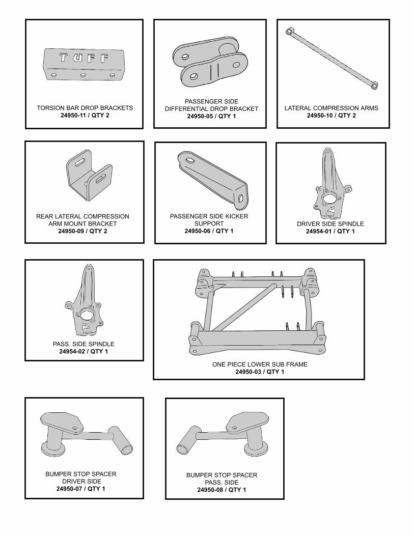
PART NUMBER : 24940 1997 — CURR. FORD F150 W/4.2 OR 4.6 LITER 4.5” SUSPENSION SYSTEM WITH FRONT SPINDLES Part # Description Qty. 24954-01 Driver Side Spindle 1 24954-02 Passenger Side Spindle 1 24950-03 One Piece Lower Sub Frame 1 24950-05 Pass. Side Differential Drop Bracket 1 24950-06 Pass. Side Differential Kicker Support 1 24950-07 Driver Side Bump Stop Bracket 1 24950-08 Pass. Side Bump Stop Bracket 1 24950-09 Rear Lateral Compression Arm Mounts 2 24950-10 Lateral Compression Arms 2 24950-11 Torsion Bar Drop Brackets 2 24950NB Hardware Bag 1 24950SL Poly Bushings & Sleeve Bag 1 BL401 4” Rear Lifted Blocks 2 TCI-R31 Rear Add-A-Leafs 2 CB38 3/8” Centering Bolts and Nuts 1 5U-283R 9/16” x 3 1/2” x 12 1/2” Round U-bolts 4 24940INST Instruction Sheet 1
This box kit will not fit vehicles that have the 5.4 liter engine. If the vehicle that you are working on has the 5.4 liter engine, please contact Tuff Country or your local Tuff Country dealer and order part # 24950 Tuff Country EZ-Ride Suspension recommends using a medium off set tire and wheel combination. The stock wheels will not work in combination with the new spindle design. Congratulations on your selection to purchase a Tuff Country EZ-Ride Suspension System. We at Tuff Country are proud to offer a high quality product at the industries most competitive pricing. Thank you for your confidence in us, and our product. Before installation begins, it is the customers/installers responsibility to make sure that all parts are on hand. If any parts are missing, please feel free to call one of our customer service representative @ (800) 288-2190. Tuff Country EZ-Ride Suspension highly recommends that a qualified and or certified installer performs this installation. If you desire to return your vehicle to stock, it is the customers responsibility to save all stock hardware.
IMPORTANT CUSTOMER INFORMATION
This vehicles reaction and handling characteristics may differ from standard cars and/or trucks. Modifications to improve and/or enhance off road performance may raise the intended center of gravity. Extreme caution must be utilized when encountering driving conditions which may cause vehicle imbalance or loss of control. DRIVE SAFELY! Avoid abrupt maneuvers, such as sudden sharp turns which could cause a roll over, resulting in serious injury or death. It is the customers responsibility to make sure that a re-torque is performed on all hardware associated with this suspension system after the first 100 miles of installation. It is also the customers responsibility to do a complete re-torque after every 3000 miles or after every off road use. After the original installation, Tuff Country EZ-Ride Suspension also recommends having the alignment check every 6 months to ensure proper tracking, proper wear on tires and front end components. Tuff Country EZ-Ride Suspension take no responsibility for abuse, improper installation or improper suspension maintenance. It is the responsibility of the customer or the installer to wear safety glasses at all times when performing this installation. It is the customers/installers responsibility to read and understand all steps before installation begins. OEM manual should be used as a reference guide. The Tuff Country EZ-Ride Suspension product safety label that is included in your kit box must be installed inside the cab in plain view of all occupants. It is the responsibility of the installers to make sure that the rear view mirror hanger is hung from the rear view mirror. The rear view mirror hanger has instructions on proper post installation procedure. Make sure to use locktite on all new and stock hardware associated with this installation.
INSTALLATION MANUAL 4.5” I.F.S. SUSPENSION
1997- CURR. FORD F150 W/4.2 OR 4.6 LITER
PART # 24940 SJ101402

LIMITED LIFETIME WARRANTY Notice to all Tuff Country EZ-Ride Suspension customers: It is your responsibility to keep your original sales receipt! If failure should occur on any Tuff Country EZ-Ride Suspension component, your original sales receipt must accompany the warranted unit to receive warranty. Warranty will be void if the customer can not provide the original sales receipt. Do not install a body lift in conjunction with a suspension system. If a body lift is used in conjunction with any Tuff Country EZ-Ride Suspension product, your Tuff Country EZ-Ride Suspension WARRANTY WILL BE VOID. Tuff Country Inc. (“Tuff Country”) suspension products are warranted to be free from defects in material and workmanship for life if purchased, installed and maintained on a non-commercial vehicle; otherwise, for a period of twelve (12) months, from the date of purchase and installation on a commercial vehicle, or twelve thousand (12,000) miles (which ever occurs first). Tuff Country does not warrant or make any representations concerning Tuff Country Products when not installed and used strictly in accordance with the manufacturer’s instructions for such installation and operation and accordance with good installation and maintenance practices of the automotive industry. This warranty does not apply to the cosmetic finish of Tuff Country products nor to Tuff Country products which have been altered, improperly installed, maintained, used or repaired, or damaged by accident, negligence, misuse or racing. (“Racing is used in its broadest sense, and, for example, without regards to formalities in relation to prizes, competition, etc.) This warranty is void if the product is removed from the original vehicle and re-installed on that or any other vehicle. This warranty is exclusive and is in lieu of any implied warranty of merchantability, fitness for a particular purpose or other warranty of quality, whether express or implied, except the warranty of title. All implied warranties are limited to the duration of this warranty. The remedies set forth in this warranty are exclusive. This warranty excludes all labor charges or other incidental of consequential damages. Any part or product returned for warranty claim must be returned through the dealer of the distributor from whom it was purchased. Tuff Country reserves the right to examine all parts returned to it for warranty claim to determine whether or not any such part has failed because of defect in material or workmanship. The obligation of Tuff Country under this warranty shall be limited to repairing, replacing or crediting, at its option, any part or product found to be so defective. Regardless of whether any part is repaired, replaced or credited under this warranty, shipping and/or transportation charges on the return of such product must be prepaid by the customer under this warranty.
Special Note: After the installation is complete, a front end alignment is required. Also, some vehicles may need to have a exhaust modification performed. Special Note: After completion of the installation and the new tires and wheels have been installed, trimming of the plastic valance may be needed. Tuff Country recommends running a 315/75R16 for maximum tire clearance. For a list of all parts, please refer to the Parts Description Page, at the end of the Installation Manual. Please Follow Instruction Carefully
Before installation begins, drive and check to make sure there are no uncommon sounds and or frame damage. Also at this time measure from the center of the hub to the bottom of the fender well and record measurements below. Pre Installation Measurements: Driver Side Front:______________________________ Passenger Side Front:__________________________ Driver Side Rear:______________________________ Passenger Side Rear:__________________________ At the end of the installation take the same measurements and compare to the pre-installation measurements. Post Installation Measurements: Driver Side Front:______________________________ Passenger Side Front:__________________________ Driver Side Rear:______________________________ Passenger Side Rear:__________________________
Please follow instructions carefully:
Front End Installation: 1. To begin installation, block the rear tires of the vehicle so that the vehicle is stable and can’t roll backwards. Safely lift the front of the vehicle and support the frame with a pair of jack stands. Place a jack stand on both the driver and passenger side. Next, remove the wheels and tires from both sides. 2. Remove the stock front upper skid plate. Save the stock upper skid plate and hardware for later re-installation. 3. Working on the driver side, remove the stock hardware on the top of the stock shock. The upper stock hardware may be discarded. Remove the stock hardware on the lower shock mount and save hardware for later re-installation. The stock shock may be discarded. Special

Note: New longer front shocks are needed, if you have not already ordered shocks, please contact Tuff Country or your local Tuff Country dealer and order the proper shocks. Tuff Country recommends using a 23” fully extended nitrogen gas shock. Repeat procedure on the passenger side. 4. Remove the stock front driveline from the stock location on the front differential. Save the stock hardware for later re-installation. Special Note: Tie the stock front drive line up and out of the way. 5. Measure exposed threads on the torsion bar adjustment bolt and record measurement here for a later reference. Record Driver Side measurement here:______________ Record Passenger Side measurement here:__________
See Illustration # 1 6. Working on the driver side, attach the torsion bar removing tool to the stock torsion bar cross member, making sure that the unloading bolt in the center of the torsion bar removing tool is in the small divot of the stock torsion bar key. Adjust the torsion bar key up high enough so that the stock small metal adjusting block and bolt can be removed. Set the stock torsion bar block and hardware a side for later re-installation. Repeat procedure on passenger side.
See Illustration # 2 7. Mark both torsion bars before removal so that they can be re-installed back into the same location. Example: Driver vs. Passenger and front vs. rear. Tap the stock torsion bars forward until the stock torsion bar cross member can be removed. 8. Working on the driver side, remove the stock bolts that connects the stock torsion bar cross member to the stock mounting point. Save the stock hardware for later re-installation. Repeat procedure on the passenger side. Remove the stock torsion bar cross member from the stock location and set a side for later re-installation. 9. Working on the driver side, slide the stock torsion bar out of the stock rear lower control arm and set a side for later re-installation. Repeat procedure on passenger side. 10. Working on the driver side, remove the stock sway bar end link from the stock sway bar and the stock lower control arm and discard the stock end link and all the stock hardware. Repeat procedure on the passenger side. 11. Working on the driver side, remove the stock bolt that connects the stock brake line bracket to the stock frame rail. Save the stock hardware for later re-installation. 12. Working on the driver side, remove any stock brake line bracket that connect to the stock steering knuckle and the stock upper control arms.
13. Working on the driver side, remove the (2) stock bolts that connect the stock brake caliper to the stock rotor. Save the stock hardware for later re-installation. Using a bungee cord, carefully tie the stock brake caliper up and out of the way in the fender well. Special Note: Take special care not to kink or over extend the stock brake line. 14. Working on the driver side, remove the stock cap right in the middle of the stock hub assembly. Set the stock cap a side for later re-installation. 15. Working on the driver side, remove the stock cotter pin and nut that connects the stock axle to the hub assembly. Save the stock nut for later re-installation.
See Illustration # 3 16. Working on the driver side, loosen the stock nut that connects the stock upper control arm ball joint to the stock steering knuckle. Do not remove the stock nut completely. Carefully break the stock taper on the stock upper control arm ball joint. Special Note: Take special care not to rip or tear the stock ball joint dust boot. 17. Working on the driver side, loosen the stock nut that connects the stock lower control arm ball joint to the stock steering knuckle. Do not remove the stock nut completely. Carefully break the stock taper on the stock lower control arm ball joint. Special Note: Take special care not to rip or tear the stock ball joint dust boot. 18. Working on the driver side, loosen the stock nut that connects the stock outer tie rod ball joint to the stock steering knuckle. Do not remove the stock nut completely. Carefully break the stock taper on the stock outer tie rod ball joint. Special Note: Take special care not to rip or tear the stock outer tie rod ball joint dust boot. 19. Working on the driver side, move back to the stock nuts holding the upper control arm ball joint, the lower control arm ball joint and the outer tie rod ball joint to the stock steering knuckle and remove completely. Save all (3) nuts and washers for later re-installation. 20. Working on the driver side, use a suitable removal tool to remove the stock axle from the hub assembly. Special Note: Take special care not to damage the stock threads on the stock axle. 21. Carefully remove the stock hub assembly and the stock steering knuckle form the stock location. 22. Working on the driver side stock hub assembly, remove the (3) stock bolts that connect the stock hub assembly to the stock steering knuckle. Save the stock hardware and stock hub assembly for later re-installation. A new steering knuckle is used, the stock steering knuckle can be discarded.
23. Locate the new driver side steering knuckle. Using the stock hardware that was removed from step # 22, secure the new driver side steering knuckle to the stock hub assembly. Torque to 92 ft lbs. Special Note: Make sure to use thread locker or lock tite. 24. Set the new driver side steering knuckle and the stock hub assembly a side for later re-installation. 25. Working on the driver side, scribe a mark on the CV plate and another directly across to the stock differential, this will allow you to re-install the stock CV back into the stock location at a later step.
See Illustration # 4 26. Working on the driver side, unbolt and remove the (6) stock bolts holding the inner CV to the stock differential. Save the stock hardware for later re-installation. Set the stock axle a side for later re-installation. 27. Working on the driver side, remove the stock hardware that connects the stock lower control arm into the stock front and rear lower control arm location. Save the stock front lower control arm hardware. The stock rear lower control arm hardware may be discarded. Set the stock lower control arm a side for later re-installation. 28. Repeat step’s 11 - 27 on the passenger side. 29. Working on the driver side, remove the stock bolt that connects the lower rear portion of the front differential to the stock rear cross member. Save the stock hardware for later re-installation. 30. Working on the driver side, remove the (2) stock bolts that connect the stock rear cross member to the stock rear lower control arm drop bracket. Repeat procedure on the passenger side. The stock rear cross member and hardware may be discarded.
31. Locate the new one piece lower sub frame, the stock front lower control arm hardware that was removed from step # 27, (2) 5/8” x 5 1/2” bolts, (4) 5/8” flat washers, (2) 5/8” unitorque nuts and (2) 5/8” lock washers. Install the new one piece lower sub frame into the stock front and rear lower control arm pockets. Secure the front portion of the sub frame into the stock front lower control arm pocket using the stock hardware. Special Note: Make sure to use thread locker or lock tite. Do not tighten at this point. Secure the rear portion of the new sub frame into the stock rear lower control arm pocket using the new 5/8” x 5 1/2” bolts and hardware. Do not tighten at this point.
See Illustration # 5 / Front Location See Illustration # 6 / Rear Location
32. Locate the driver and passenger side bump stop spacers, (2) 3/8” x 1 1/4” self threading bolts, (2) 3/8” flat washers and (2) 3/8” lock washers. Working on the driver side rear lower control arm pocket, remove the new 5/8” x 5 1/2” bolt and hardware that connects the new one
piece lower sub frame into the stock rear lower control arm pocket. Save the new hardware for later re-installation. Install the new driver side bump stop spacer into the rear pocket on the new one piece lower sub frame located in the stock rear lower control arm pocket. Secure using the new 5/8” x 5 1/2” bolt and hardware that was removed earlier in this step. Do not tighten at this point. Special Note: The driver and passenger side bump stop brackets are a mirror image of each other, to determine the driver side bump stop spacer from the passenger side bump stop spacer, the hole in the upper portion of the bump stop bracket needs to be towards the rear of the vehicle. See Illustration # 7 for proper placement. Repeat procedure on the passenger side.
See Illustration # 7 33. Working on the driver side, hold the new driver side bump stop bracket flush with the stock bump stop location. Using the new driver side bump stop bracket as a guide, carefully drill a 5/16” hole into the stock bump stop location. Secure the new driver side bump stop spacer to the bottom side of the bump stop location using the new 3/8” x 1 1/4” self threading bolt and hardware. Torque to 34 ft. lbs. Special Note: Make sure to use thread locker or lock tite. Repeat procedure on the passenger side.
See Illustration # 7 34. Secure the front differential with a pair of hydraulic floor jacks. Place one jack stand on the driver side and one on the passenger side. 35. Working on the driver side, remove the stock bolt that holds the upper portion of the differential into the stock location. Save the stock hardware for later re-installation. Repeat procedure on the passenger side. 36. Carefully lower down on both jack stands at the same time until the front and rear portion of the driver side differential seat into the new pockets on the front and rear portion of the new one piece lower sub frame. 37. Locate the stock front differential rear hardware that was removed in step # 29. Also, locate the stock front differential front hardware that was removed from step # 35. Secure the front and rear portion of the stock differential into the new lower one piece sub frame using the stock hardware Special Note: Make sure to use thread locker or lock tite. Do not tighten at this point.
See Illustration # 8 / Front Location See Illustration # 9 / Rear Location
38. Locate the passenger side differential relocation bracket, the passenger side kicker support bracket, the passenger side stock hardware that was removed from step # 35, (1) 7/16” x 4 1/2” bolt, (1) 7/16” x 1 1/2” bolt, (4) 7/16” flat washers, (2) 7/16” unitorque nuts and (2) 7/16” lock washers. Working on the passenger side, install the new passenger side differential drop bracket into the stock location and secure using the stock

hardware. Special Note: The new passenger side differential drop bracket has a bend on one of the legs of the bracket. This leg of the bracket needs to be installed towards the rear of the vehicle. Make sure to use thread locker or lock tite. Do not tighten at this point.
See Illustration # 10 39. Raise up on the hydraulic floor jack until the passenger side of the front differential seats properly into the newly installed passenger side differential drop bracket. Also at this time install the passenger side kicker support bracket. Secure the passenger side kicker support bracket, the newly installed passenger side differential drop bracket using the new 7/16” x 4 1/2” bolt and hardware. Special Note: Make sure to use thread locker or lock tite. Do not tighten at this point.
See Illustration # 11
40. Working on the passenger side, install the rear portion of the passenger side kicker support bracket to the inner part of the passenger side stock rear lower control arm pocket. Secure using the new 7/16” x 1 1/2” bolt and hardware. Special Note: Make sure to use thread locker or lock tite. Do not tighten at this point.
See Illustration # 11
41. Remove the 2 hydraulic floor jacks from under the front differential.
42. Move back to all new and stock hardware associated with the new lower one piece sub frame, the new and stock hardware associated with the front differential, the front passenger side differential drop bracket and the passenger side kicker support and torque to proper specs. Refer to the torque setting sheet at the end of the installation manual. 43. Locate the stock driver and passenger side lower control arms that were removed in step # 27, (4) 5/8” x 5 1/2” bolts, (8) 5/8” flat washers, (4) 5/8” unitorque nuts and (4) 5/8” lock washers. Working on the driver side, install the stock lower control arm into the front and rear pockets of the new one piece lower sub frame using the new 5/8” x 5 1/2” bolts and hardware. Special Note: Make sure to use thread locker or lock tite. Do not tighten at this point. Repeat procedure on the passenger side.
See Illustration # 12 / Front Portion See Illustration # 13 / Rear Portion
44. Locate the stock driver and passenger side axles and the stock hardware that was removed in step # 25. Working on the driver side install the driver side axle to the stock front differential and secure using the stock hardware. Torque to 65 ft lbs. Special Note: Make sure to use thread locker or lock tite. Also, make sure that the stock axle is re-installed back into the stock location on the stock front differential. Refer to the scribe mark that was made in step # 25. Repeat
procedure on the passenger side. See Illustration # 14
45. Locate the new driver side steering knuckle and stock hub assembly, the stock hardware for the upper control arm ball joint, lower control arm ball joint and outer tie rod ball joint that was removed from step # 19. Using the stock hardware, secure the new driver side steering knuckle and stock hub assembly to the stock upper control arm ball joint, the stock lower control arm ball joint and the stock outer tie rod assembly. Torque the stock hardware on the upper and lower ball joints to 85 ft lbs. Torque the outer tie rod ball joint hardware to 68 ft. lbs. Special Note: When installing the new driver side spindle, make sure that the stock brake line is located towards the inside of the vehicle. Make sure to use thread locker or lock tite. Also when performing this step, slide the stock axle into the stock hub assembly location. Repeat procedure on the passenger side using the passenger side steering knuckle.
See Illustration # 15
46. Locate the stock hardware that connects the stock front axle to the stock hub assembly that was removed in step # 15. Working on the driver side, secure the stock front axle to the hub assembly using the stock hardware. Torque to 112 ft. lbs. Make sure to use thread locker or lock tite. Also, make sure to re-install the stock cotter pin. Replace the stock hub assembly cap that was removed from step # 14. Repeat procedure on the passenger side. 47. Move back to all associated hardware that connects the stock lower control arms to the new one piece lower sub frame and torque 125 ft. lbs. 48. Locate the stock brake caliper hardware that was removed in step # 13. Working on the driver side, re-install the stock brake caliper to the stock rotor and secure using the stock hardware. Torque to 76 ft. lbs. Repeat procedure on the passenger side. 49. Locate (2) new torsion bar drop blocks, (6) 1/2” x 1 1/2” bolts, (12) 1/2” flat washers, (6) 1/2” unitorque nuts and (6) lock washers. Working on the driver side, install the new torsion bar drop block into the stock location and secure using the new 1/2” x 1 1/2” bolts and hardware. Torque to 85 ft. lbs. Make sure to use thread locker or lock tite. Repeat procedure on the passenger side.
See Illustration # 16
50. Locate the stock driver and passenger side torsion bars that were removed from step # 9. Working on the driver side, slide the stock torsion bar into the stock lower control arm and let hang. Special Note: Make sure to re-install the stock torsion bar back into the stock location. Example: Driver vs. Passenger and front vs. rear. Repeat procedure on the passenger side.

cross member, carefully drill a 1/2” hole into the stock transfer case cross member where the mark was scribed in step # 56. Repeat procedure on the passenger side. 58. Working on the driver side lateral compression arm, remove the new rear lateral compression arm mount and save hardware for later re-installation. Repeat procedure on passenger side. 59. Working on the driver side, secure the new rear lateral compression arm mount to the previously drilled hole in the stock transfer case cross member using the new 1/2” x 1 1/2” bolt and hardware. Torque to 85 ft lbs. Make sure to use thread locker or lock tite. Repeat procedure on the passenger side.
See Illustration # 17 60. Working on the driver side, secure the new lateral compression arm into the newly installed rear lateral compression arm mount using the new 1/2” x 3 1/2” bolt and hardware. Torque to 85 ft lbs. Make sure to use thread locker or lock tite. Repeat procedure on the passenger side.
61. Working on the driver side, torque the 1/2” bolt and hardware that connects the new lateral compression arm to the front mount on the newly installed lower one piece sub frame. Torque to 85 ft lbs. Make sure to use thread locker or lock tite. Repeat procedure on the passenger side.
62. Move back to all newly installed brackets and make sure that all stock and new hardware is torqued to proper specifications. Special Note: Refer to the torque sheet at the end of the installation manual. 63. Locate (2) 3/8” x 10” bolts, (2) sway bar end links, (8) sway bar end link bushings, (8) sway bar end link washers and (2) 3/8” unitorque nuts. Working on the driver side, install the new sway bar end link and hardware into the stock location. Torque to 32 ft lbs. Make sure to use thread locker or lock tite. Repeat procedure on the passenger side.
See Illustration # 18
64. Locate the new front shocks (Not included in this suspension system) and the lower stock hardware that was removed from step # 3. Install the new shock into the stock upper location using the new hardware that was included with the new shocks. Torque to 28 ft lbs. Secure the bottom of the new shock into the stock location using the stock hardware. Torque to 65 ft lbs. Make sure to use thread locker or lock tite.
65. Locate the stock drive line hardware that was removed in step # 4. Re-install the stock front drive line to the front differential using the stock hardware. Torque to 45 ft lbs. Make sure to use thread locker or lock tite.
51. Locate the stock torsion bar cross member and the stock hardware that was removed in step # 8. Working on the driver side, install the stock torsion bar cross member to the newly installed torsion bar drop bracket and secure using the stock hardware. Torque to 75 ft lbs. Make sure to use thread locker or lock tite. Special Note: Install the stock torsion bar cross member to the inside of the new torsion bar drop blocks. Repeat procedure on the passenger side.
See Illustration # 16
52. Locate the stock driver and passenger side torsion bar key’s that were removed from step # 6. Working on the driver side, install the stock torsion bar key back into the stock torsion bar cross member. Holding the stock torsion bar key into the stock location, slide the driver side torsion bar into the stock torsion bar key. Repeat procedure on the passenger side. 53. Locate the small metal adjusting blocks and bolts that were removed from step # 6. Working on the driver side, attach the torsion bar removing tool, making sure that the unloading bolt in the center tool is in the small divot of the torsion bar key. Adjust the torsion bar key up high enough so that the small metal adjusting block and stock bolt can be re-installed, Refer back to step # 5 and adjust the stock bolt to the stock location. Repeat procedure on passenger side. Remove the torsion bar removing tool. 54. Locate (2) new lateral compression arms, (8) MO2050 poly bushings, (4) 1/2” x 2 1/8” crush sleeve and (2) lube packs. Install the new poly bushings and sleeves into each end of the new lateral compression arms. Special Note: Make sure to use the lithium grease that is provide when installing the new bushings and sleeves. 55. Locate (2) 1/2” x 3 1/2” bolts, (4) 1/2” flat washers, (2) 1/2” unitorque nuts, (2) 1/2” lock washers and the new lateral compression arms. Working on the driver side, install the new lateral compression arm to the front mount on the rear portion of the new lower one piece sub frame and secure using the new 1/2” x 3 1/2” bolt and hardware. Make sure to use thread locker or lock tite. Do not tighten at this point. Repeat procedure on the passenger side. 56. Locate (2) new rear lateral compression arm mounts, (2) 1/2” x 1 1/2” bolts, (2) 1/2” x 3 1/2” bolts, (8) 1/2” flat washers, (4) 1/2” unitorque nuts and (4) 1/2” lock washers. Install the new rear lateral compression arm mounts to the previously installed lateral compression arms and secure using the new 1/2” x 3 1/2” bolts and hardware. Make sure to use thread locker or lock tite. Do not tighten at this point. Working on the driver side, hold the new lateral compression arm up to the stock transfer case cross member and scribe a mark on the stock transfer case cross member were the rear mount is to be located. Special Note: Make sure that the new lateral compression arms are parallel to the frame

stock spring clamps. Safely remove the stock centering bolt and discard. Install the new rear add-a-leaf to the stock spring assembly. Secure the new rear add-a-leaf to the stock spring assembly using the new 3/8” center bolt and nut. Special Note: The new rear add-a-leaf has an off set centering pin hole, the longer side of the new rear add-a-leaf needs to be installed towards the rear of the vehicle. The new rear add-a-leaf should be installed into the stock spring assembly in progression in order. The new rear add-a-leaf should be installed between the stock overload and the stock spring pack. The stock overload is usually the un-arched spring at the bottom of the stock leaf pack. Also, Tuff Country EZ-Ride Suspension recommends not using any air tools when installing the new add-a-leafs into the stock spring assembly. If air tools are used the centering bolt may strip, causing the stock spring assembly to come apart. Torque the new centering bolt and nut to 28 ft. lbs. Remove the “C” clamps from the stock spring assembly. With a suitable cutting tool, cut off the extra thread from the new centering bolt. Repeat procedure on passenger side.
See Illustration # 19 76. Locate (2) new 4” lifted rear blocks. Working on the driver side, install (1) new 4” lifted rear block between the stock rear axle and the stock spring assembly. Special Note: The new 4” lifted block has a slight taper to it, the small end of the new block needs to be installed with the small end towards the front of the vehicle. Repeat procedure on passenger side.
See Illustration # 19
77. Raise up on both hydraulic floor jacks at the same time until the driver and passenger side stock spring assembly seats flush with newly installed 4” block. 78. Locate (4) new 9/16” x 3 1/2” x 12 1/2” round U-bolts, (8) 9/16” U-bolt high nuts, (8) 9/16” U-bolt washers and the stock upper U-bolt plate that were removed from step # 72. Working on the driver side, install (2) new 9/16” x 3 1/2” x 12 1/2” round U-bolts into the stock location and secure using the new 9/16” high nuts and washers. Torque to 120 ft lbs. With a suitable cutting tool, cut off the extra thread from the new U-bolts. Repeat procedure on passenger side.
See Illustration # 19
79. Locate the new rear shocks (Not included in this suspension system). Working on the driver side, install the new rear shocks absorbers using the stock hardware removed from step # 71. Repeat procedure on passenger side. 80. Check and double check to make sure that all step related with the rear end were performed properly. Check and double check to make sure that all stock and new hardware is torque to proper torque specifications. Use the torque setting sheet at the end of the installation manual.
66. Locate the stock front upper skid plate and the hardware that was removed from step # 2. Install the stock front upper skid plate into the stock location and secure using the stock hardware. Torque to 28 ft lbs. Make sure to use thread locker or lock tite. 67. Install the tires and wheels and carefully lower the vehicle to the ground. 68. Locate the stock hardware that was removed from step # 11. Working on the driver side, install the stock brake line bracket into the stock location and secure using the stock hardware. Torque to 18 ft lbs. Make sure to use thread locker or lock tite.
Congratulations. Front End Installation Complete. Rear End Installation: 69. To begin installation, block the front tires of the vehicle so that the vehicle is stable and can’t roll forward. Safely lift the rear of the vehicle and support the frame with a pair of jack stands. Place a jack stand on both the driver and passenger side. Next, remove the wheels and tires from both sides. 70. Position a pair of hydraulic floor jacks under the rear axle. Place one jack stand on the driver side and one on the passenger side. Raise up on both hydraulic floor jacks at the same time until they make contact with the rear axle. 71. Working on the driver side, remove the stock shock from the stock location and save the stock hardware for later re-installation. The stock shock may be discard. Special Note: New longer rear shocks are needed, if you have not already ordered shocks, please contact Tuff Country or your local Tuff Country dealer and order the proper shocks. Tuff Country recommends using a 30” fully extended nitrogen gas shock. 72. Working on the driver side, remove the (2) stock rear U-bolts and discard. Set the upper U-bolt plate a side for later re-installation. Repeat procedure on passenger side. 73. Lower down on both hydraulic floor jacks at the same time until the stock springs separate from the stock rear axle. Lower down approximately 4”. Special Note: Make sure not to over extended any brake lines or hoses when lowering the stock rear axle. This will allow you enough room for the new rear blocks and add-a-leafs to be installed. 74. Working on the driver side, remove the stock block from the stock location and discard. Repeat procedure on the passenger side. 75. Locate (2) new rear add-a-leafs, (2) 3/8” centering bolts and nuts. Working on the driver side, place a pair of “C” clamps around the rear springs about 2” from the

81. Carefully remove both hydraulic floor jacks from under the vehicle. 82. Install the tire wheels and carefully lower the vehicle to the ground. CONGRATULATIONS INSTALLATION COMPLETE
SPECIAL NOTE: A FRONT END ALIGNMENT IS REQUIRED ONCE THE
INSTALLATION IS COMPLETE
IF YOU HAVE ANY QUESTION AND OR CONCERS ABOUT THE INSTALLATION PLEASE FEEL FREE TO CONTACT TUFF COUNTRY
Torque Settings
5/16” 15—18 ft lbs. 3/8” 28—32 ft lbs. 7/16” 30—35 ft lbs. 1/2” 65—85 ft lbs. 9/16” 85—120 ft lbs. 5/8” 95—130 ft lbs. 3/4” 100—140 ft lbs. Special Post Installation Procedure: Once the new Suspension System has been installed. Check the fluid level in the front differential. Top off the fluid with proper differential fluid. On occasion the owner of the vehicle may find burping of fluid coming out of the front vent tube.

ILLUSTRATION # 1
ILLUSTRATION # 2
STOCK TORSION BAR
STOCK TORSION BAR
TORSION BAR PULLER
TORSION BAR CROSS MEMBER
TORSION BAR ADJUSTMENT BOLT
STOCKTORSION BAR
KEY
STOCKTORSION BAR
KEY

ILLUSTRATION # 3
ILLUSTRATION # 4
STOCK DIFFERENTIAL
CV PLATE
STOCK AXLE NUT
STOCK HUB ASSEMBLY
STOCK BRAKE CALIPER
STOCK HARDWARE
REFERENCEMARK

ILLUSTRATION # 5
ILLUSTRATION # 6
NEW ONE-PIECE SUB FRAME (FRONT VIEW)
STOCK HARDWARE
NEW ONE-PIECE SUB FRAME (REAR VIEW)
NEW 5/8” X 5 1/2” BOLTAND HARDWARE

ILLUSTRATION # 7
ILLUSTRATION # 8
STOCK FRONT DIFFERENTIAL
NEW PASSENGER SIDEBUMP STOP BRACKET
STOCK FRONT DIFFERENTIAL BOLT AND HARDWARE
NEW SUB FRAME
FRONT OF VEHICLE
NEW 3/8” X 1 1/4”SELF THREADING
BOLD & HARDWARE
STOCK FRONT UPPER DIFFERENTIAL
MOUNTING POINT

ILLUSTRATION # 9
ILLUSTRATION # 10
NEW PASSENGER SIDEDIFFERENTIAL DROP
BRACKET
STOCK FRONTDIFFERENTIAL
STOCK HARDWARE
STOCK HARDWARE
NEW SUB FRAME

ILLUSTRATION # 11
ILLUSTRATION # 12
STOCK FRONT LOWERCONTROL ARMS
NEW 7/16” X 4 1/2”BOLT & HARDWARE
STOCK HARDWARE
NEW ONE PIECE SUBFRAME
NEW 7/16” X 1 1/2”BOLT & HARDWARE
NEW PASSENGER SIDEKICKER SUPPORT BRACKET
STOCK HARDWARE
NEW 5/8” X 5 1/2”BOLT & HARDWARE

ILLUSTRATION # 13
ILLUSTRATION # 14
STOCK FRONT LOWERCONTROL ARM
NEW 5/8” X 5 1/2“ BOLT& HARDWARE
NEW LOWER ONE PEICE SUBFRAME
STOCK DIFFERENTIAL
CV PLATE
STOCK HARDWARE
REFERENCEMARK

ILLUSTRATION # 16
NEW DRIVER SIDESPINDLE
ILLUSTRATION # 15
NEW TORSION BARDROP BLOCK
STOCK HARDWARE
STOCK HARDWARE

ILLUSTRATION # 17
ILLUSTRATION # 18
STOCK TRANSFER CASE CROSS MEMBER
NEW REAR LATERAL COMPRESSION ARM MOUNTS
NEW SWAYBAR ENDLINK& HARDWARE
1/2” X 1 1/2”BOLTS & HARDWARE

ILLUSTRATION # 19
NEW REAR ADD-A-LEAF
NEW 9/16” X 3 1/2” X 12 1/2”ROUND U-BOLTS &
HARDWARE
NEW 4” REAR LIFTBLOCK
TORSION BAR DROP BRACKETS24950-11 / QTY 2
LATERAL COMPRESSION ARMS24950-10 / QTY 2
REAR LATERAL COMPRESSIONARM MOUNT BRACKET
24950-09 / QTY 2
PASSENGER SIDE KICKER SUPPORT
24950-06 / QTY 1
ONE PIECE LOWER SUB FRAME24950-03 / QTY 1
PASSENGER SIDE DIFFERENTIAL DROP BRACKET
24950-05 / QTY 1
DRIVER SIDE SPINDLE24954-01 / QTY 1
PASS. SIDE SPINDLE24954-02 / QTY 1
BUMPER STOP SPACERDRIVER SIDE
24950-07 / QTY 1
BUMPER STOP SPACERPASS. SIDE
24950-08 / QTY 1