installation manual ahu communication kit gebruikershandleiding/prdca0.pdf · shock, injury or...
TRANSCRIPT
P/NO : MFL50024804
www.lg.com
INSTALLATION MANUAL
AHU COMMUNICATION KIT• Please read this installation manual completely before installing the product.• Installation work must be performed in accordance with the national wiring standards by authorized personnel only.• Please retain this installation manual for future reference after reading it thoroughly.
MODEL : PRDCA0
2 AHU Communication Kit
AHU Communication Kit Manual
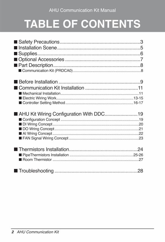
TABLE OF CONTENTSn Safety Precautions.............................................................3n Installation Scene...............................................................5n Supplies..............................................................................6n Optional Accessories .........................................................7n Part Description..................................................................8
n Communication Kit (PRDCA0)...................................................................8
n Before Installation ..............................................................9n Communication Kit Installation ........................................11
n Mechanical Installation.............................................................................11n Electric Wiring Work............................................................................13-15n Controller Setting Method...................................................................16-17
n AHU Kit Wiring Configuration With DDC.........................19n Configuration Concept .............................................................................19n DI Wring Concept.....................................................................................20n DO Wring Concept ...................................................................................21n AI Wring Concept .....................................................................................22n FAN Signal Wiring Concept .....................................................................23
n Thermistors Installation....................................................24n PipeThermistors Installation ...............................................................25-26n Room Thermistor .....................................................................................27
n Troubleshooting ...............................................................28
Safety Precautions
Installation Manual 3
n Installation
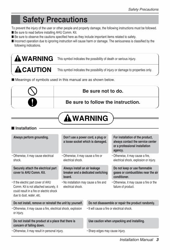
Safety PrecautionsTo prevent the injury of the user or other people and property damage, the following instructions must be followed.n Be sure to read before installing AHU Comm. Kit.n Be sure to observe the cautions specified here as they include important items related to safety.n Incorrect operation due to ignoring instruction will cause harm or damage. The seriousness is classified by the
following indications.
n Meanings of symbols used in this manual are as shown below.
WARNING
CAUTION
This symbol indicates the possibility of death or serious injury.
This symbol indicates the possibility of injury or damage to properties only.
Be sure not to do.
Be sure to follow the instruction.
WARNING
Always perform grounding.
• Otherwise, it may cause electricalshock.
Donʼt use a power cord, a plug ora loose socket which is damaged.
• Otherwise, it may cause a fire orelectrical shock.
For installation of the product,always contact the service centeror a professional installationagency.
• Otherwise, it may cause a fire,electrical shock, explosion or injury.
Securely attach the electrical partcover to AHU Comm. Kit.
• If the electric part cover of AHUComm. Kit is not attached securely, itcould result in a fire or electric shockdue to dust, water, etc.
Always install an air leakagebreaker and a dedicated switchingboard.
• No installation may cause a fire andelectrical shock.
Do not keep or use flammablegases or combustibles near the airconditioner.
• Otherwise, it may cause a fire or thefailure of product.
Do not install, remove or reinstall the unit by yourself.
• Otherwise, it may cause a fire, electrical shock, explosionor injury.
Do not disassemble or repair the product randomly.
• It will cause a fire or electrical shock.
Do not install the product at a place that there isconcern of falling down.
• Otherwise, it may result in personal injury.
Use caution when unpacking and installing.
• Sharp edges may cause injury.
Safety Precautions
4 AHU Communication Kit
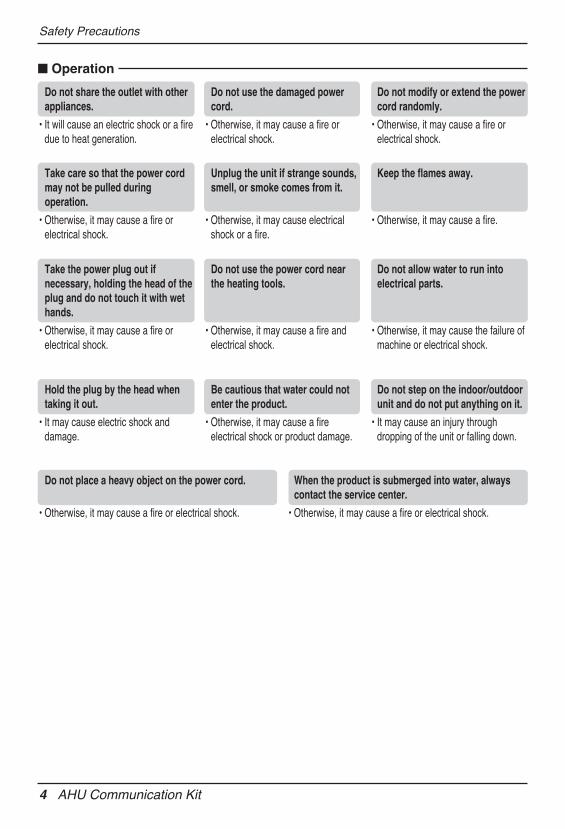
n Operation
Do not share the outlet with otherappliances.
• It will cause an electric shock or a firedue to heat generation.
Do not use the damaged powercord.
• Otherwise, it may cause a fire orelectrical shock.
Do not modify or extend the powercord randomly.
• Otherwise, it may cause a fire orelectrical shock.
Take care so that the power cordmay not be pulled duringoperation.
• Otherwise, it may cause a fire orelectrical shock.
Unplug the unit if strange sounds,smell, or smoke comes from it.
• Otherwise, it may cause electricalshock or a fire.
Keep the flames away.
• Otherwise, it may cause a fire.
Take the power plug out ifnecessary, holding the head of theplug and do not touch it with wethands.
• Otherwise, it may cause a fire orelectrical shock.
Do not use the power cord nearthe heating tools.
• Otherwise, it may cause a fire andelectrical shock.
Do not allow water to run intoelectrical parts.
• Otherwise, it may cause the failure ofmachine or electrical shock.
Hold the plug by the head whentaking it out.
• It may cause electric shock anddamage.
Be cautious that water could notenter the product.
• Otherwise, it may cause a fireelectrical shock or product damage.
Do not step on the indoor/outdoorunit and do not put anything on it.
• It may cause an injury throughdropping of the unit or falling down.
Do not place a heavy object on the power cord.
• Otherwise, it may cause a fire or electrical shock.
When the product is submerged into water, alwayscontact the service center.
• Otherwise, it may cause a fire or electrical shock.
Installation Manual 5
Installation Scene
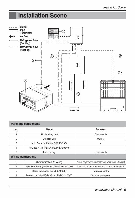
Installation Scene
SignalPipeThermistor
6
8
9
7
2
4
3
1
5
Air flowRefrigerant flow(Cooling) Refrigerant flow(Heating)
1
2
3
4
5
Air Handling Unit
Outdoor Unit
AHU Communication Kit(PRDCA0)
AHU EEV Kit(PRLK048A0/PRLK096A0)
Field piping
Field supply
Multi V
-
-
Field supply
Parts and components
6
7
8
9
Communication Kit Wiring
Pipe thermistors (EBG61287703/EBG61287704)
Room thermistor (EBG36949303)
Remote controller(PQRCVSL0 / PQRCVSL0QW)
Power supply and communication between comm. kit and outdoor unit
Evaporator (In/Out) control of Air Handling Unit
Return air control
Optional accessory
Wiring connections
No. Name Remarks
6 AHU Communication Kit
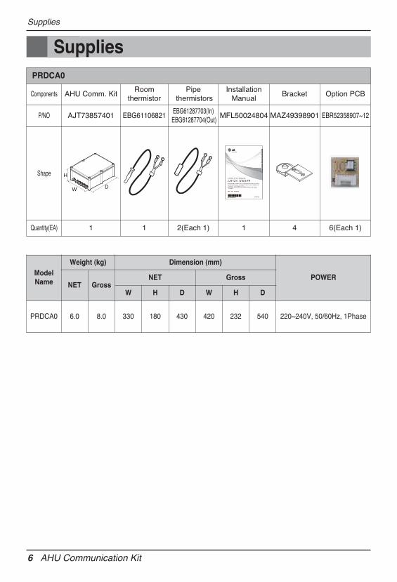
Supplies
SuppliesPRDCA0
Components AHU Comm. KitRoom
thermistorPipe
thermistorsInstallation
ManualBracket Option PCB
P/NO AJT73857401 EBG61106821EBG61287703(In)EBG61287704(Out)
MFL50024804 MAZ49398901 EBR52358907~12
Shape
Quantity(EA) 1 1 2(Each 1) 1 4 6(Each 1)
W D
H
ModelName
Weight (kg) Dimension (mm)
POWERNET Gross
NET Gross
W H D W H D
PRDCA0 6.0 8.0 330 180 430 420 232 540 220~240V, 50/60Hz, 1Phase
Installation Manual 7
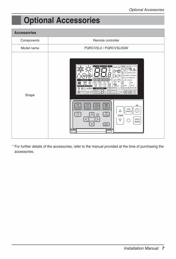
Optional Accessories
Optional Accessories
* For further details of the accessories, refer to the manual provided at the time of purchasing theaccessories.
Accessories
Components Remote controller
Model name PQRCVSL0 / PQRCVSL0QW
Shape
8 AHU Communication Kit
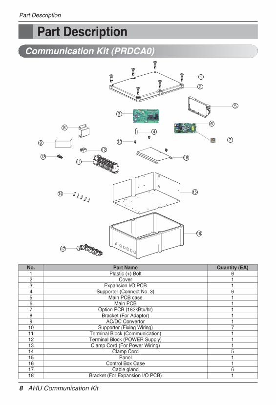
Part Description
Part DescriptionCommunication Kit (PRDCA0)
1
2
12
4
5
13
8
3
9
14
17
11
10
16
15
18
7
6
No. Part Name Quantity (EA)1 Plastic (+) Bolt 62 Cover 13 Expansion I/O PCB 14 Supporter (Connect No. 3) 65 Main PCB case 16 Main PCB 17 Option PCB (182kBtu/hr) 18 Bracket (For Adaptor) 19 AC/DC Convertor 110 Supporter (Fixing Wiring) 711 Terminal Block (Communication) 112 Terminal Block (POWER Supply) 113 Clamp Cord (For Power Wiring) 114 Clamp Cord 515 Panel 116 Control Box Case 117 Cable gland 618 Bracket (For Expansion I/O PCB) 1
Installation Manual 9
Before Installation
n Don't install or operate the unit in rooms mentioned below.① Where mineral oil, like cutting oil is present.② Where the air contains high levels of salt such as air near the ocean.③ Where sulphurous gas is present such as that in areas of hot spring.④ In vehicles or vessels.⑤ Where voltage fluctuates a lot such as that in factories.⑥ Where high concentration of vapor spray are present.⑦ Where machines generating electromagnetic waves are present.⑧ Where acidic or alkaline vapor is present.⑨ The option boxes must be installed with entrances downward.
CAUTION
Before Installation
n Check the mentioned below, when you apply the AHU(Field supply).① If the AHU (Field supply) provided in the field is exclusively for heating, you must not
change the operating mode to cooling on the remote controller. If not, it can cause electricshock, injury or death. If you want to operate in cooling mode, AHU (Field supply) mustcomply with the following details.(Following)- The insulation level of AHU (Field supply) motor must be ʻFʼ or above, and the protection
level must satisfy ʻIP 54ʼ.- AHU (Field supply) must have the drain pan installed.
② Fan speed button on the wired remote controller(PQRCVSL0 /PQRCVSL0QW) is not operated.
③ For refrigerant piping of outdoor unit, refer to the installation manual supplied with theoutdoor unit.
④ For installation of the wired remote controller(PQRCVSL0 /PQRCVSL0QW), refer to themanual supplied with the wired remote controller.
⑤ For protecting the refrigerant cycle, the outside temperature of heat exchanger have to beover 5℃.
n AHU Communication Kit
① Thermistor cable and remote controller wire should be located at least 50mm away frompower supply wires and from wires to the controller. Not following this guideline may resultin malfunction due to electrical noise.
② Use only specified wires, and tightly connect wires to the terminals. Keep wiring in neatorder so that it does not obstruct other equipment. Incomplete connections could result inoverheating, and in worse case electric shock or fire.
10 AHU Communication Kit
Before Installation
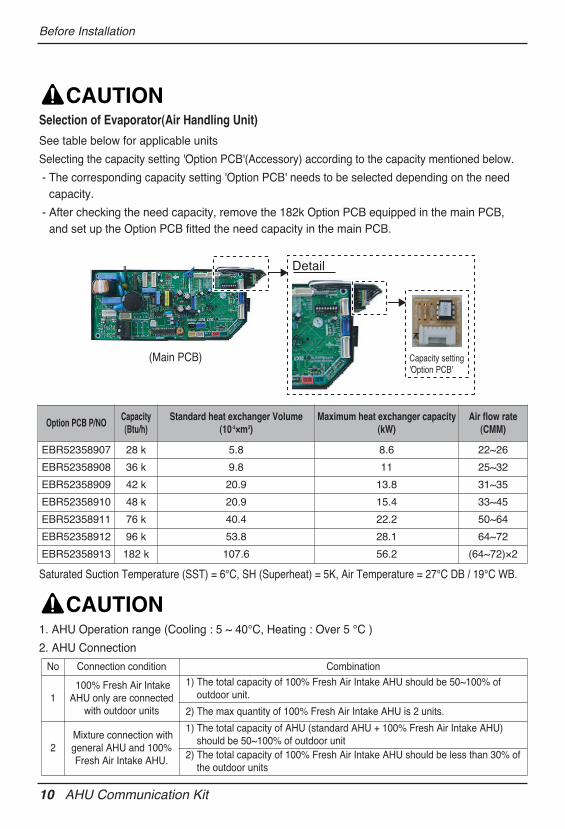
Selection of Evaporator(Air Handling Unit)
See table below for applicable units
Selecting the capacity setting 'Option PCB'(Accessory) according to the capacity mentioned below.
- The corresponding capacity setting 'Option PCB' needs to be selected depending on the needcapacity.
- After checking the need capacity, remove the 182k Option PCB equipped in the main PCB, and set up the Option PCB fitted the need capacity in the main PCB.
CAUTION
1. AHU Operation range (Cooling : 5 ~ 40℃, Heating : Over 5 ℃ )
2. AHU Connection
CAUTION
Saturated Suction Temperature (SST) = 6°C, SH (Superheat) = 5K, Air Temperature = 27°C DB / 19°C WB.
Capacity setting 'Option PCB'
Detail
Option PCB P/NOCapacity(Btu/h)
Standard heat exchanger Volume (10-3×m3)
Maximum heat exchanger capacity(kW)
Air flow rate(CMM)
EBR52358907 28 k 5.8 8.6 22~26
EBR52358908 36 k 9.8 11 25~32
EBR52358909 42 k 20.9 13.8 31~35
EBR52358910 48 k 20.9 15.4 33~45
EBR52358911 76 k 40.4 22.2 50~64
EBR52358912 96 k 53.8 28.1 64~72
EBR52358913 182 k 107.6 56.2 (64~72)×2
(Main PCB)
No Connection condition Combination
1100% Fresh Air Intake
AHU only are connectedwith outdoor units
1) The total capacity of 100% Fresh Air Intake AHU should be 50~100% ofoutdoor unit.
2) The max quantity of 100% Fresh Air Intake AHU is 2 units.
2Mixture connection withgeneral AHU and 100%Fresh Air Intake AHU.
1) The total capacity of AHU (standard AHU + 100% Fresh Air Intake AHU)should be 50~100% of outdoor unit
2) The total capacity of 100% Fresh Air Intake AHU should be less than 30% ofthe outdoor units
Installation Manual 11
Communication Kit Installation
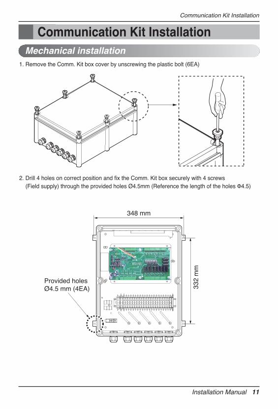
Communication Kit InstallationMechanical installation
1. Remove the Comm. Kit box cover by unscrewing the plastic bolt (6EA)
2. Drill 4 holes on correct position and fix the Comm. Kit box securely with 4 screws (Field supply) through the provided holes Ø4.5mm (Reference the length of the holes Φ4.5)
348 mm
332
mm
Provided holesØ4.5 mm (4EA)
12 AHU Communication Kit
Communication Kit Installation
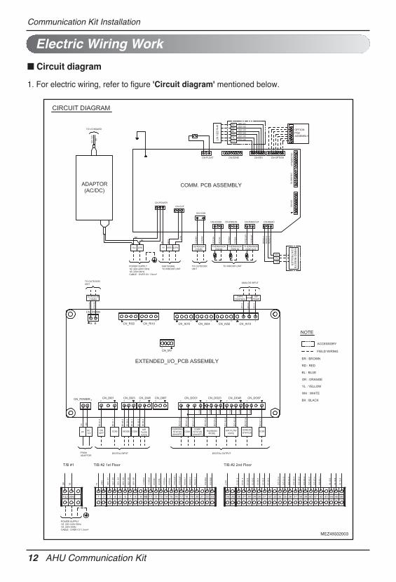
Electric Wiring Work
1. For electric wiring, refer to figure 'Circuit diagram' mentioned below.
n Circuit diagram
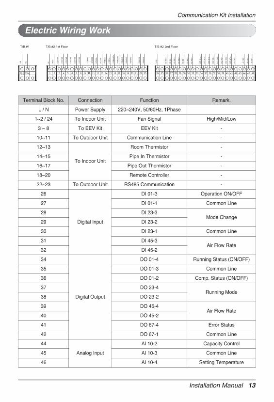
Installation Manual 13
Electric Wiring Work
Communication Kit Installation
Terminal Block No. Connection Function Remark.
L / N Power Supply 220~240V, 50/60Hz, 1Phase
1~2 / 24 To Indoor Unit Fan Signal High/Mid/Low
3 ~ 8 To EEV Kit EEV Kit -
10~11 To Outdoor Unit Communication Line -
12~13
To Indoor Unit
Room Thermistor -
14~15 Pipe In Thermistor -
16~17 Pipe Out Thermistor -
18~20 Remote Controller -
22~23 To Outdoor Unit RS485 Communication -
26
Digital Input
DI 01-3 Operation ON/OFF
27 DI 01-1 Common Line
28 DI 23-3Mode Change
29 DI 23-2
30 DI 23-1 Common Line
31 DI 45-3Air Flow Rate
32 DI 45-2
34
Digital Output
DO 01-4 Running Status (ON/OFF)
35 DO 01-3 Common Line
36 DO 01-2 Comp. Status (ON/OFF)
37 DO 23-4Running Mode
38 DO 23-2
39 DO 45-4Air Flow Rate
40 DO 45-2
41 DO 67-4 Error Status
42 DO 67-1 Common Line
44
Analog Input
AI 10-2 Capacity Control
45 AI 10-3 Common Line
46 AI 10-4 Setting Temperature
14 AHU Communication Kit
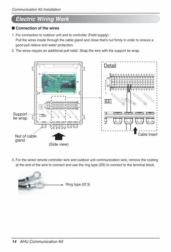
3. For the wired remote controller wire and outdoor unit communication wire, remove the coatingat the end of the wire to connect and use the ring type (Ø3) to connect to the terminal block.
Ring type (Ø 3)
Communication Kit Installation
Electric Wiring Work
1. For connection to outdoor unit and to controller (Field supply) : Pull the wires inside through the cable gland and close that's nut firmly in order to ensure agood pull relieve and water protection.
2. The wires require an additional pull-relief. Strap the wire with the support tie wrap.
Supporttie wrap
Nut of cable gland
(Side view)
Cable Insert
Detail
n Connection of the wires
Installation Manual 15
Communication Kit Installation
Electric Wiring Work
n All field supplied parts and materials and electric works must be conform to local codes.n Use copper wire only.n All wiring must be performed by an authorized electrician.n A main switch or other means for disconnection, having a contact separation in all poles,
must be incorporated in the fixed wiring in accordance with relevant local and nationallegislation.
n Refer to the installation manual attached to the outdoor unit for the size of power supplyelectric wire connected to the outdoor unit, the capacity of the circuit breaker and switch,wiring and wiring instructions.
CAUTION
16 AHU Communication Kit
Communication Kit Installation
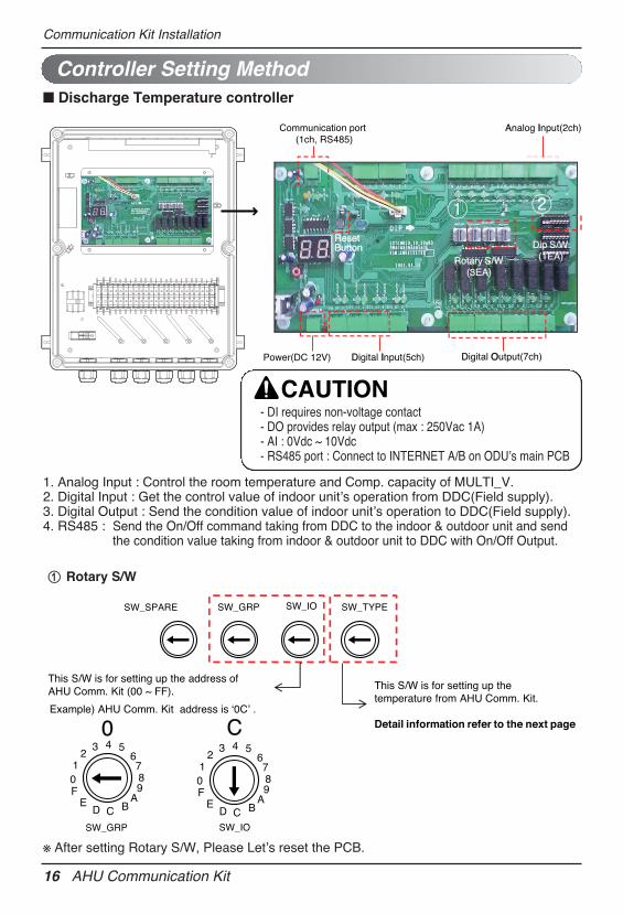
Controller Setting Method
Dip S/W(1EA)
Communication port(1ch, RS485)
Analog IInput(2ch)
Power(DC 12V) Digital IInput(5ch) Digital OOutput(7ch)
Rotary S/W
ResetResetButtonButton
(3EA)
SW_SPARE SW_GRP SW_IO SW_TYPE
This S/W is for setting up the address of AHU Comm. Kit (00 ~ FF). This S/W is for setting up the
temperature from AHU Comm. Kit.
Detail information refer to the next pageExample) AHU Comm. Kit address is ‘0C’ .
SW_GRP SW_IO
0 C
01
23 4 5
6789
ABCD
EF
01
23 4 5
6789
ABCD
EF
1. Analog Input : Control the room temperature and Comp. capacity of MULTI_V.2. Digital Input : Get the control value of indoor unitʼs operation from DDC(Field supply).3. Digital Output : Send the condition value of indoor unitʼs operation to DDC(Field supply).4. RS485 : Send the On/Off command taking from DDC to the indoor & outdoor unit and send
the condition value taking from indoor & outdoor unit to DDC with On/Off Output.
※ After setting Rotary S/W, Please Letʼs reset the PCB.
n Discharge Temperature controller
- DI requires non-voltage contact- DO provides relay output (max : 250Vac 1A)- AI : 0Vdc ~ 10Vdc- RS485 port : Connect to INTERNET A/B on ODUʼs main PCB
CAUTION
① Rotary S/W
Installation Manual 17
Communication Kit Installation
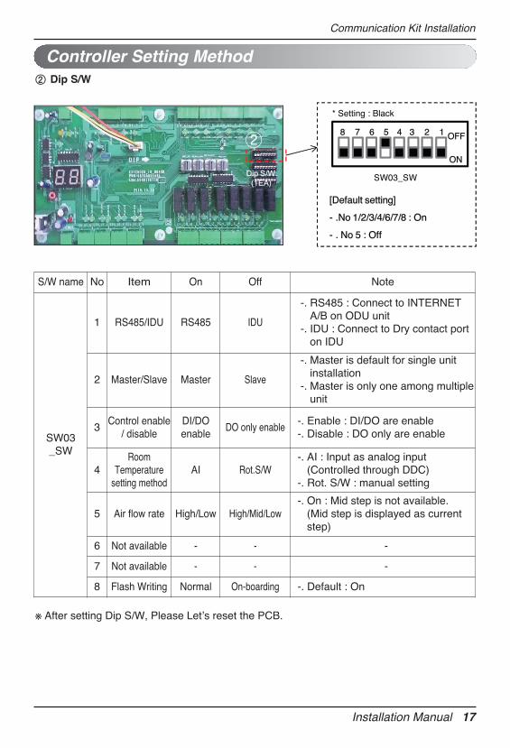
※ After setting Dip S/W, Please Letʼs reset the PCB.
Controller Setting Method
Dip S/W(1EA)
ON
8 7 6 5 4 3 2 1 OFF
SW03_SW
* Setting : Black
[Default setting]
- .No 1/2/3/4/6/7/8 : On
- . No 5 : Off
② Dip S/W
S/W name No Item On Off Note
SW03_SW
1 RS485/IDU RS485 IDU
-. RS485 : Connect to INTERNETA/B on ODU unit
-. IDU : Connect to Dry contact porton IDU
2 Master/Slave Master Slave
-. Master is default for single unitinstallation
-. Master is only one among multipleunit
3Control enable
/ disable DI/DOenable
DO only enable -. Enable : DI/DO are enable-. Disable : DO only are enable
4Room
Temperaturesetting method
AI Rot.S/W-. AI : Input as analog input
(Controlled through DDC)-. Rot. S/W : manual setting
5 Air flow rate High/Low High/Mid/Low -. On : Mid step is not available.
(Mid step is displayed as currentstep)
6 Not available - - -
7 Not available - - -
8 Flash Writing Normal On-boarding -. Default : On
18 AHU Communication Kit
Communication Kit Installation
Controller Setting Method
DipS/W W
Rotary S/W DipS/W
Rotary S/W
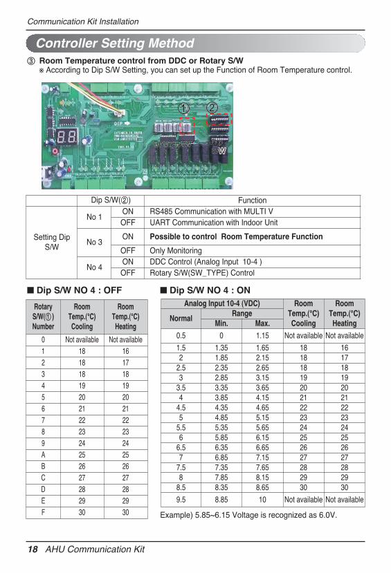
③ Room Temperature control from DDC or Rotary S/W※ According to Dip S/W Setting, you can set up the Function of Room Temperature control.
n Dip S/W NO 4 : OFF n Dip S/W NO 4 : ON
Example) 5.85~6.15 Voltage is recognized as 6.0V.
Dip S/W(②) Function
Setting DipS/W
No 1 ON RS485 Communication with MULTI VOFF UART Communication with Indoor Unit
No 3 ON Possible to control Room Temperature Function
OFF Only Monitoring
No 4ON DDC Control (Analog Input 10-4 )OFF Rotary S/W(SW_TYPE) Control
Rotary S/W(① )Number
RoomTemp.(℃)Cooling
RoomTemp.(℃)Heating
0 Not available Not available 1 18 162 18 173 18 184 19 195 20 206 21 217 22 228 23 239 24 24A 25 25B 26 26C 27 27D 28 28E 29 29F 30 30
Analog Input 10-4 (VDC) RoomTemp.(℃)Cooling
RoomTemp.(℃)Heating
Normal Range
Min. Max. 0.5 0 1.15 Not available Not available
1.5 1.35 1.65 18 162 1.85 2.15 18 17
2.5 2.35 2.65 18 183 2.85 3.15 19 19
3.5 3.35 3.65 20 204 3.85 4.15 21 21
4.5 4.35 4.65 22 225 4.85 5.15 23 23
5.5 5.35 5.65 24 246 5.85 6.15 25 25
6.5 6.35 6.65 26 267 6.85 7.15 27 27
7.5 7.35 7.65 28 288 7.85 8.15 29 29
8.5 8.35 8.65 30 30
9.5 8.85 10 Not available Not available
Installation Manual 19
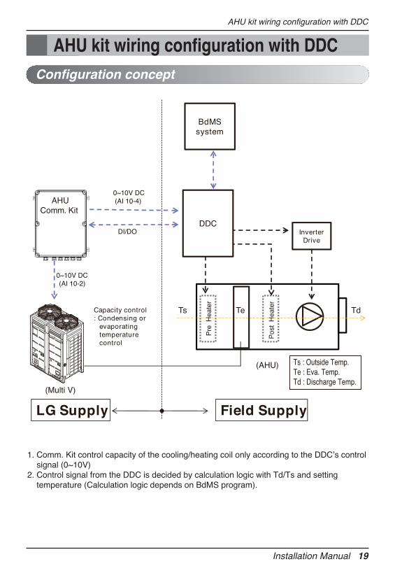
AHU kit wiring configuration with DDC
AHU Comm. Kit
(Multi V)
BdMSsystem
0~10V DC(AI 10-4)
DI/DO
0~10V DC (AI 10-2)
Capacity control : Condensing or
evaporatingtemperature control
InverterDrive
(AHU)
DDC
TdTeTs
Pos
t H
eate
r
Pre
Hea
ter
Field SupplyLG Supply
Ts : Outside Temp.Te : Eva. Temp.Td : Discharge Temp.
Configuration concept
1. Comm. Kit control capacity of the cooling/heating coil only according to the DDCʼs controlsignal (0~10V)
2. Control signal from the DDC is decided by calculation logic with Td/Ts and settingtemperature (Calculation logic depends on BdMS program).
AHU kit wiring configuration with DDC
20 AHU Communication Kit
AHU kit wiring configuration with DDC
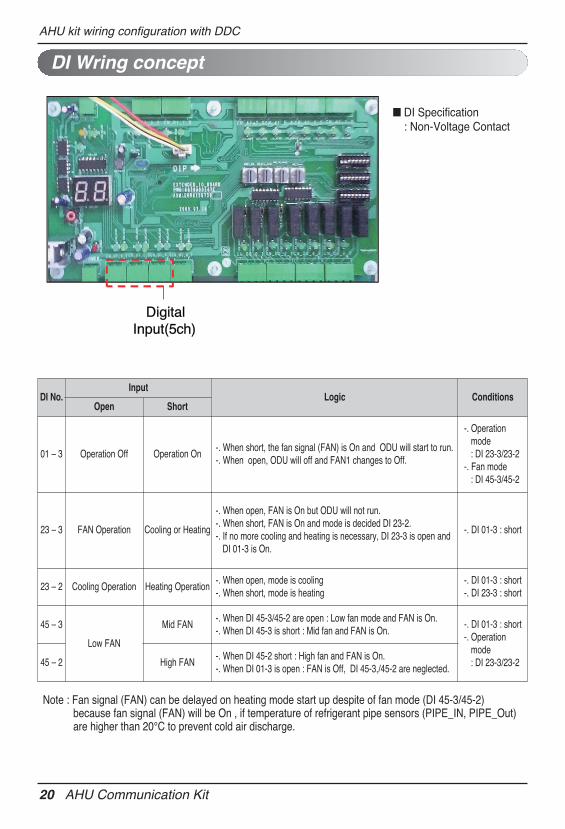
DI Wring concept
Digital Input(5ch)
Note : Fan signal (FAN) can be delayed on heating mode start up despite of fan mode (DI 45-3/45-2) because fan signal (FAN) will be On , if temperature of refrigerant pipe sensors (PIPE_IN, PIPE_Out) are higher than 20℃ to prevent cold air discharge.
n DI Specification: Non-Voltage Contact
DI No. Input
Logic ConditionsOpen Short
01 – 3 Operation Off Operation On-. When short, the fan signal (FAN) is On and ODU will start to run.-. When open, ODU will off and FAN1 changes to Off.
-. Operationmode : DI 23-3/23-2
-. Fan mode : DI 45-3/45-2
23 – 3 FAN Operation Cooling or Heating
-. When open, FAN is On but ODU will not run.-. When short, FAN is On and mode is decided DI 23-2.-. If no more cooling and heating is necessary, DI 23-3 is open and
DI 01-3 is On.
-. DI 01-3 : short
23 – 2 Cooling Operation Heating Operation -. When open, mode is cooling-. When short, mode is heating
-. DI 01-3 : short-. DI 23-3 : short
45 – 3
Low FAN
Mid FAN-. When DI 45-3/45-2 are open : Low fan mode and FAN is On.-. When DI 45-3 is short : Mid fan and FAN is On.
-. DI 01-3 : short-. Operation
mode : DI 23-3/23-2 45 – 2 High FAN
-. When DI 45-2 short : High fan and FAN is On.-. When DI 01-3 is open : FAN is Off, DI 45-3,/45-2 are neglected.
Installation Manual 21
AHU kit wiring configuration with DDC
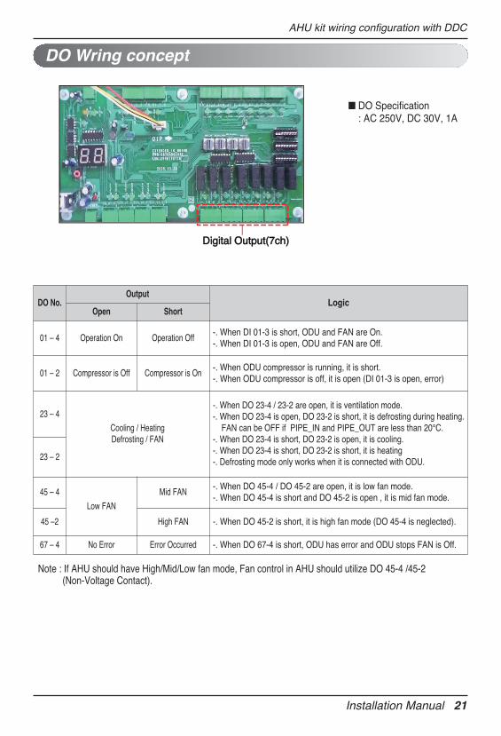
DO Wring concept
Digital Output(7ch)Digital Output(7ch)
Note : If AHU should have High/Mid/Low fan mode, Fan control in AHU should utilize DO 45-4 /45-2 (Non-Voltage Contact).
n DO Specification: AC 250V, DC 30V, 1A
DO No. Output
LogicOpen Short
01 – 4 Operation On Operation Off-. When DI 01-3 is short, ODU and FAN are On.-. When DI 01-3 is open, ODU and FAN are Off.
01 – 2 Compressor is Off Compressor is On-. When ODU compressor is running, it is short.-. When ODU compressor is off, it is open (DI 01-3 is open, error)
23 – 4
Cooling / HeatingDefrosting / FAN
-. When DO 23-4 / 23-2 are open, it is ventilation mode.-. When DO 23-4 is open, DO 23-2 is short, it is defrosting during heating.
FAN can be OFF if PIPE_IN and PIPE_OUT are less than 20℃.-. When DO 23-4 is short, DO 23-2 is open, it is cooling.-. When DO 23-4 is short, DO 23-2 is short, it is heating-. Defrosting mode only works when it is connected with ODU.23 – 2
45 – 4
Low FAN
Mid FAN-. When DO 45-4 / DO 45-2 are open, it is low fan mode.-. When DO 45-4 is short and DO 45-2 is open , it is mid fan mode.
45 –2 High FAN -. When DO 45-2 is short, it is high fan mode (DO 45-4 is neglected).
67 – 4 No Error Error Occurred -. When DO 67-4 is short, ODU has error and ODU stops FAN is Off.
22 AHU Communication Kit
AHU kit wiring configuration with DDC
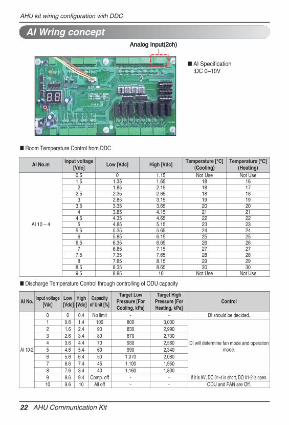
AI Wring conceptAnalog Input(2ch)Analog Input(2ch)
n AI Specification :DC 0~10V
AI No.mInput voltage
[Vdc]Low [Vdc] High [Vdc]
Temperature [℃](Cooling)
Temperature [℃](Heating)
AI 10 – 4
0.5 0 1.15 Not Use Not Use1.5 1.35 1.65 18 162 1.85 2.15 18 17
2.5 2.35 2.65 18 183 2.85 3.15 19 19
3.5 3.35 3.65 20 204 3.85 4.15 21 21
4.5 4.35 4.65 22 225 4.85 5.15 23 23
5.5 5.35 5.65 24 246 5.85 6.15 25 25
6.5 6.35 6.65 26 267 6.85 7.15 27 27
7.5 7.35 7.65 28 288 7.85 8.15 29 29
8.5 8.35 8.65 30 309.5 8.85 10 Not Use Not Use
n Room Temperature Control from DDC
n Discharge Temperature Control through controlling of ODU capacity
AI No.Input voltage
[Vdc]Low[Vdc]
High[Vdc]
Capacity of Unit [%]
Target LowPressure [ForCooling, kPa]
Target HighPressure [ForHeating, kPa]
Control
AI 10-2
0 0 0.4 No limit - - DI should be decided.1 0.6 1.4 100 800 3,000
DI will determine fan mode and operationmode.
2 1.6 2.4 90 830 2,9903 2.6 3.4 80 870 2,7304 3.6 4.4 70 930 2,5605 4.6 5.4 60 990 2,3406 5.6 6.4 50 1,070 2,0807 6.6 7.4 45 1,100 1,9508 7.6 8.4 40 1,160 1,8009 8.6 9.4 Comp. off - - If it is 9V, DO 01-4 is short, DO 01-2 is open.10 9.6 10 All off - - ODU and FAN are Off.
AHU kit wiring configuration with DDC
Installation Manual 23
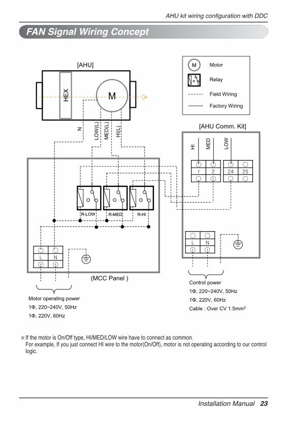
FAN Signal Wiring Concept
※If the motor is On/Off type, HI/MED/LOW wire have to connect as common. For example, If you just connect HI wire to the motor(On/Off), motor is not operating according to our controllogic.
HI
MED
LOW
[AHU Comm. Kit]
HE
X
(MCC Panel )
HI(L
)
ME
D(L
)
LOW
(L)
M
N
[AHU]
R-HIR-MEDR-LOW
Motor operating power
1Φ, 220~240V, 50Hz
1Φ, 220V, 60Hz
M Motor
Relay
Field Wiring
Factory Wiring
Control power
1Φ, 220~240V, 50Hz
1Φ, 220V, 60Hz
Cable : Over CV 1.5mm2
24 AHU Communication Kit
Thermistors Installation
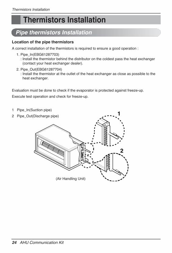
Pipe thermistors Installation
Location of the pipe thermistors
A correct installation of the thermistors is required to ensure a good operation :
1. Pipe_In(EBG61287703): Install the thermistor behind the distributor on the coldest pass the heat exchanger(contact your heat exchanger dealer).
2. Pipe_Out(EBG61287704): Install the thermistor at the outlet of the heat exchanger as close as possible to theheat exchanger.
Evaluation must be done to check if the evaporator is protected against freeze-up.
Execute test operation and check for freeze-up.
1 Pipe_In(Suction pipe)
2 Pipe_Out(Discharge pipe)
(Air Handling Unit)
1
2
Thermistors Installation
Installation Manual 25
Thermistors Installation
Pipe thermistors Installation
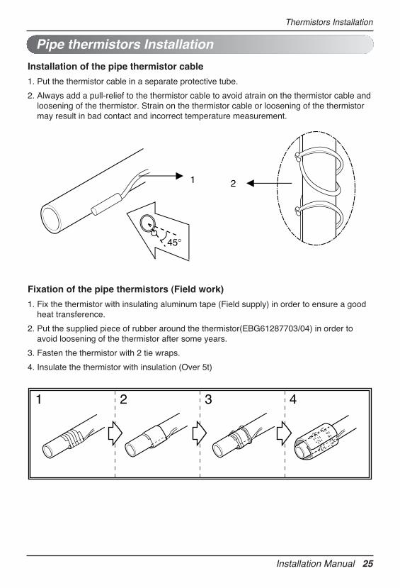
Installation of the pipe thermistor cable
1. Put the thermistor cable in a separate protective tube.
2. Always add a pull-relief to the thermistor cable to avoid atrain on the thermistor cable andloosening of the thermistor. Strain on the thermistor cable or loosening of the thermistormay result in bad contact and incorrect temperature measurement.
2
45°
1
Fixation of the pipe thermistors (Field work)
1. Fix the thermistor with insulating aluminum tape (Field supply) in order to ensure a goodheat transference.
2. Put the supplied piece of rubber around the thermistor(EBG61287703/04) in order toavoid loosening of the thermistor after some years.
3. Fasten the thermistor with 2 tie wraps.
4. Insulate the thermistor with insulation (Over 5t)
1 2 3 4
26 AHU Communication Kit
Thermistors Installation
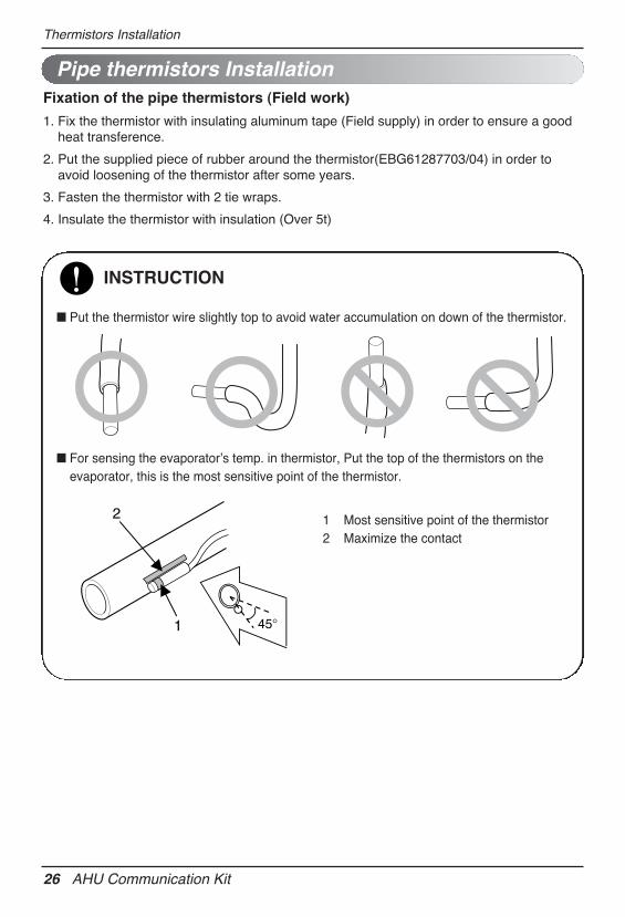
Fixation of the pipe thermistors (Field work)
1. Fix the thermistor with insulating aluminum tape (Field supply) in order to ensure a goodheat transference.
2. Put the supplied piece of rubber around the thermistor(EBG61287703/04) in order toavoid loosening of the thermistor after some years.
3. Fasten the thermistor with 2 tie wraps.
4. Insulate the thermistor with insulation (Over 5t)
INSTRUCTION
n Put the thermistor wire slightly top to avoid water accumulation on down of the thermistor.
n For sensing the evaporatorʼs temp. in thermistor, Put the top of the thermistors on theevaporator, this is the most sensitive point of the thermistor.
1 Most sensitive point of the thermistor2 Maximize the contact
45°
2
1
Pipe thermistors Installation
Installation Manual 27
Thermistors Installation
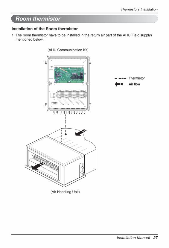
Room thermistor
Installation of the Room thermistor
1. The room thermistor have to be installed in the return air part of the AHU(Field supply)mentioned below.
Thermistor
Air flow
(Air Handling Unit)
(AHU Communication Kit)
Troubleshooting
Troubleshooting
AHU Communication Kit does not work
No power supply Check the electrical connection and voltage of the power
supply.
Wiring is wrong Check the electrical connection of the Communication Kit
(Refer to the circuit diagram of the Communication Kit)
AHU Communication Kit is broken Check the electrical and mechanical part.
Problem Cause Remedy
28 AHU Communication Kit
[Error Code]
Display Number Error Item Cause of Error
CH 01 Room TemperatureTemperature sensor disconnection or
short circuit on Room or RA of Indoor Unit
CH 02 Pipe In Temperature sensor errorTemperature sensor disconnection orshort circuit on pipe inlet of Indoor Unit
CH 03Communication error between wired
remote controller and Comm. Kit
No communication signal for more than 3minutes from wired remote controller to
the Comm. Kit
CH 05Communication error between Comm.
Kit and Outdoor Unit
No communication signal for 5 minutescontinuously from Comm. Kit to Outdoor
Unit
CH 06 Pipe Out Temperature sensor errorTemperature sensor disconnection or
short circuit on pipe outlet of Indoor Unit
CH 09 Option PCB EEPROM errorNo reading signal for 5 times continuously
from EEPROM to Comm. Kit

Installation Manual 29

30 AHU Communication Kit