installation manual bridge alarm system br-1000 · all brand and product names are trademarks,...
TRANSCRIPT

www.furuno.co.jpAll brand and product names are trademarks, registered trademarks or service marks of their respective holders.
Installation ManualBRIDGE ALARM SYSTEM BR-1000
SAFETY INSTRUCTIONS ............................................................................................................. iSYSTEM CONFIGURATION ........................................................................................................ iiEQUIPMENT LISTS..................................................................................................................... iii
1. HOW TO INSTALL THE EQUIPMENT .................................................................................1-11.1 Bridge Panel....................................................................................................................1-11.2 Processor Unit.................................................................................................................1-31.3 Cabin Panel, Timer Reset Panel.....................................................................................1-41.4 AC-DC Power Supply......................................................................................................1-51.5 Watertight Timer Reset Panel .........................................................................................1-6
2. HOW TO CONNECT EXTERNAL EQUIPMENT ..................................................................2-12.1 Connections Inside the Processor Unit ...........................................................................2-12.2 AC-DC Power Supply......................................................................................................2-52.3 Connection of ALARM IN/REMOTE ACK OUT/LOCAL ACK IN/
OPERATOR FITNESS IN Signals...................................................................................2-7
3. HOW TO SET AND CHECK THE SYSTEM .........................................................................3-13.1 How to Set and Connect the PC for Maintenance ..........................................................3-13.2 Settings for Bridge Panel BR-1010 .................................................................................3-33.3 Settings for Processor Unit BR-1020 ............................................................................3-253.4 System Operation Check ..............................................................................................3-303.5 Service Menu ................................................................................................................3-343.6 How to Edit the Alarm List.............................................................................................3-42
APPENDIX 1 JIS CABLE GUIDE...........................................................................................AP-1
PACKING LISTS....................................................................................................................... A-1OUTLINE DRAWINGS.............................................................................................................. D-1INTERCONNECTION DIAGRAMS........................................................................................... S-1PROCESSOR UNIT CONNECTION LISTS.............................................................................. S-3

The paper used in this manualis elemental chlorine free.
・FURUNO Authorized Distributor/Dealer
9-52 Ashihara-cho,Nishinomiya, 662-8580, JAPAN
Telephone : +81-(0)798-65-2111
Fax : +81-(0)798-65-4200
A : SEP 2009.Printed in JapanAll rights reserved.
Pub. No. IME-44500-A
*00016918910**00016918910*(DAMI ) BR-1000*00016918910**00016918910** 0 0 0 1 6 9 1 8 9 1 0 *
i
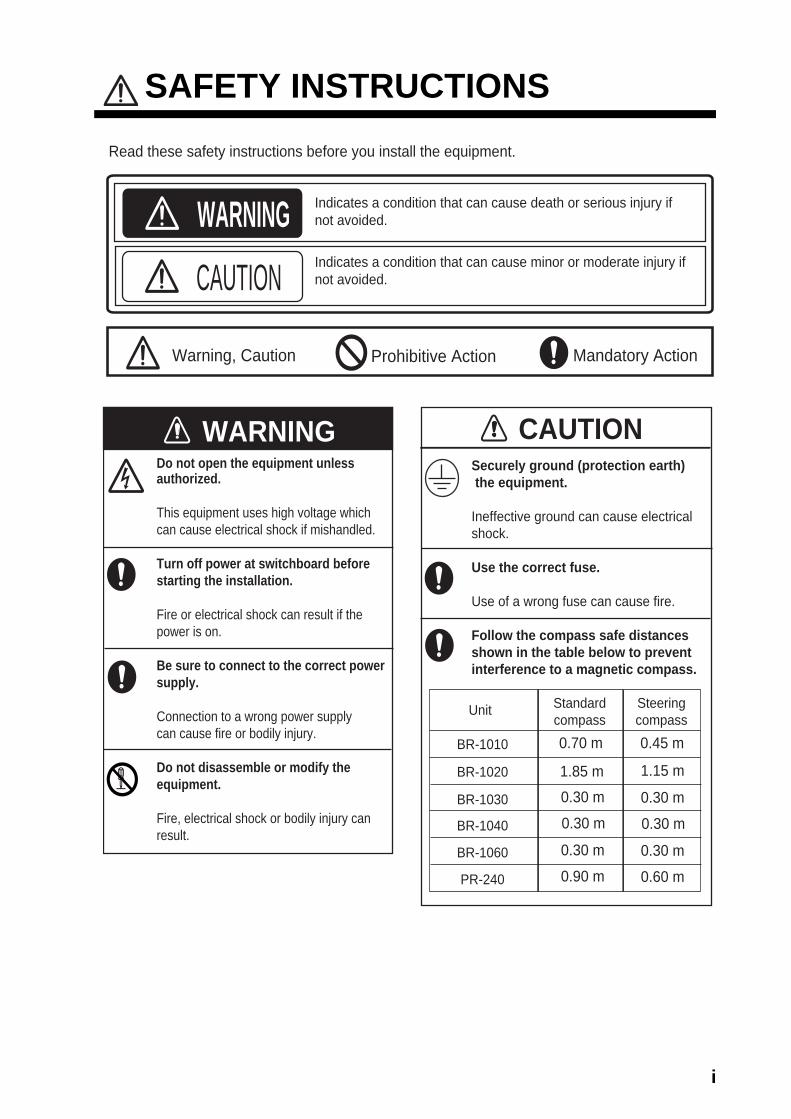
SAFETY INSTRUCTIONS
WARNING Indicates a condition that can cause death or serious injury ifnot avoided.
CAUTION Indicates a condition that can cause minor or moderate injury ifnot avoided.
Mandatory Action Prohibitive Action
Read these safety instructions before you install the equipment.
WARNINGDo not open the equipment unlessauthorized.
This equipment uses high voltage whichcan cause electrical shock if mishandled.
Turn off power at switchboard beforestarting the installation.
Fire or electrical shock can result if thepower is on.
Be sure to connect to the correct powersupply.
Connection to a wrong power supplycan cause fire or bodily injury.
Do not disassemble or modify theequipment.
Fire, electrical shock or bodily injury canresult.
Securely ground (protection earth) the equipment.
Ineffective ground can cause electricalshock.
Use the correct fuse.
Use of a wrong fuse can cause fire.
Follow the compass safe distancesshown in the table below to preventinterference to a magnetic compass.
CAUTION
Warning, Caution
Standardcompass
Steeringcompass
Unit
0.70 mBR-1010 0.45 m
1.15 m
0.30 m
1.85 m0.30 m
0.30 m0.30 m
0.30 m0.30 m
0.60 m0.90 m
BR-1020
BR-1030
BR-1040
BR-1060
PR-240

ii
SYSTEM CONFIGURATION
BRIDGE PANELBR-1010
VDRGPS
24 VDC
1 - 4 units
Autopilot (2 lines)
IAS (2 lines)
External Siren
REMOTE ACK OUT (12 lines)
LOCAL ACK IN (12 lines)
OPERATOR FITNESS IN (7 lines)
ALARM IN (48 lines)
SYSTEM FAIL OUT (2 lines)
4 - 14 units
- Dashed lines indicate optional equipment.- Environment category: All units protected from weather.
AC-DCPOWER SUPPLY
PR-240
ETHERNET HUBHUB-101
PROCESSOR UNITBR-1020
CABIN PANELBR-1030
TIMER RESET PANELBR-1040
WATERTIGHT TIMERRESET PANEL
BR-1060
100-115/200-230 VAC
PROCESSOR UNITBR-1020

iii
EQUIPMENT LISTSStandard Supply
Name Type Code No. Qty RemarksBridge Panel BR-1010 - 1Processor Unit BR-1020 - 1Cabin Panel BR-1030 - - 4-14 unitsTimer Reset Panel
BR-1040 - - 1-4 units
AC-DC Power Supply Unit
PR-240 - 1
Installation Materials
CP24-01300 000-013-149 1 Cable MJ-A3SPF0013-035 (000-135-397) + CP24-01301. See packing list at back of manual.
CP24-01401 001-041-390 - For BR-1030, BR-1040.See packing list at back of manual.
CP24-00151 005-931-190 - For PR-240.See packing list at back of manual.
Spare Parts SP24-00301 001-041-310 1 FuseFGB0-A 125V 3A PBF, 2 pcs.(000-155-850-10)

iv
Optional SupplyName Type Code No. Remarks
Watertight TimerReset Panel
BR-1060 - Installation Materials CP24-010501. See packing list at back of manual.
Processor Unit BR-1020 -Cabin Panel BR-1030 -Timer Reset Panel BR-1040 -Ethernet Hub HUB-101 -Hanger FP24-00500 000-013-160 For BR-1000Cable Assy. MJ-A6SPF0003-050C 000-154-054-10 For VDR, 5 m
MJ-A6SPF0003-100C 000-154-036-10 For VDR, 10 mMJ-A7SPF0007-050C 000-154-028-10 For GPS, 5 mMJ-A7SPF0010-100C 000-159-681-10 For GPS, 10 m
LAN Cable Set CP03-28900 000-082-658 10 m cable, two connectorsCP03-28910 000-082-659 20 m cable, two connectorsCP03-28920 000-082-660 30 m cable, two connectors

1-1
1. HOW TO INSTALL THEEQUIPMENT
Install the equipment following the points shown below.
• Select a location where the temperature and humidity are moderate and stable.• Keep the equipment away from the exhaust vents.• Provide ventilation to keep the equipment cool.• Select a location where vibration and shock are minimal.• Leave space at the sides and rear of the unit for maintenance.• Follow the safe compass distances on page i to prevent the interference to a mag-
netic compass.
1.1 Bridge PanelFlush mount
Fasten the Bridge Panel to the cutout with the hardware supplied.
1. Prepare a cutout in a console. See the outline drawing and the illustration shown below for dimensions.
NOTICEDo not apply paint, anti-corrosive sealantor contact spray to coating or plastic parts of the equipment.
Those items contain organic solvents that can damage coating and plastic parts, especially plastic connectors.
61±0.5(2.40±0.02)
110±0.5(4.33±0.02)
118±
1(4
.64±
0.04
)
221±1(8.70±0.04)
4.5(0.18)
R2.25(0.09)
61±0.5(2.40±0.02)
63.5±
0.5(2
.50±0
.02)
63.5±
0.5(2
.50±0
.02)
Dimensions in millimeters (inches)
1. HOW TO INSTALL THE EQUIPMENT
1-2
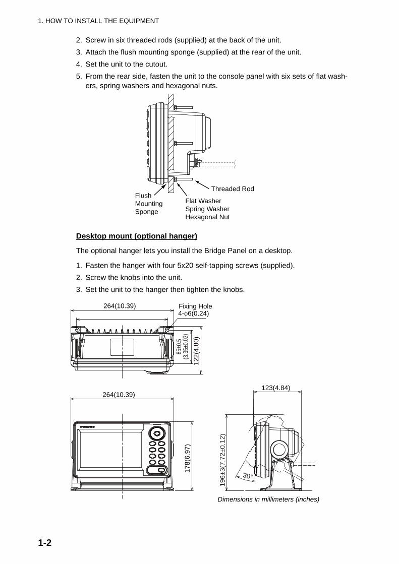
2. Screw in six threaded rods (supplied) at the back of the unit.3. Attach the flush mounting sponge (supplied) at the rear of the unit.4. Set the unit to the cutout.5. From the rear side, fasten the unit to the console panel with six sets of flat wash-
ers, spring washers and hexagonal nuts.
Desktop mount (optional hanger)
The optional hanger lets you install the Bridge Panel on a desktop.
1. Fasten the hanger with four 5x20 self-tapping screws (supplied).2. Screw the knobs into the unit.3. Set the unit to the hanger then tighten the knobs.
Threaded Rod
Flat WasherSpring WasherHexagonal Nut
FlushMountingSponge
30°
264(10.39)
178(
6.97
)
196±
3(7.
72±0
.12)
85±0
.5(3
.35±0
.02)
122(
4.80
)
4-φ6(0.24)Fixing Hole
123(4.84)
Dimensions in millimeters (inches)
264(10.39)

1. HOW TO INSTALL THE EQUIPMENT
1-3
1.2 Processor UnitA maximum of two processor units can be installed, including the optional unit. To in-stall the no. 2 processor unit, the Ethernet Hub HUB-101 is required. (For additional information, see the instruction manual (C4200707) for the HUB-101.)
Fasten the processor unit to a bulkhead or the deck as shown below.
1. Make four pilot holes for φ10 coach bolts or four fixing holes for M10 bolts. See the drawing below for mounting dimensions.
2. Fasten the unit with φ10 coach bolts or M10 bolts. (Supply bolts locally.)
Bulkhead mounting dimensions for the processor unit
354(
13.9
4)
368±
1(14
.49±
0.04
)39
2(15
.43)
360±1(14.17±0.04)
12(0.47)
R6(0.24)
158(6.22)2-φ11(0.43)
360±1(14.17±0.04)
155(6.10)12(0
.47)
21(0
.83)
Fixing Hole
Dimensions in millimeters (inches)

1. HOW TO INSTALL THE EQUIPMENT
1-4
1.3 Cabin Panel, Timer Reset PanelThe Cabin Panel and Timer Reset Panel have the same dimensions. Flush-mount the units as shown below.
A maximum of 10 channels of Cabin Panels connect to one Processor Unit. (Four of the 10 channels can be connected in parallel for a total of 14 channels.) Install the 10 channels of Cabin Panels in the Captain’s quarters, the back-up navigation officers’ quarters, and public areas. The system has five channels to test wire continuity in the Cabin Panels. Install Cabin Panels in the captain’s quarters and officers’ quarters in-dependently to conduct the wiring continuity test independently.
1. Prepare a cutout in the location. See the outline drawing and the figure shown below for dimensions.
2. Unfasten four screws from the front side of the unit to remove the rear cover.3. Put the connection cable through one of the two rubber bushes and set the rear
cover to the cutout. (Select the rubber bush most suitable for your installation.)4. Fasten the rear cover with four 4x16 self-tapping screws (supplied).5. Detach the WAGO connector from the PCB. Attach the wires to the WAGO con-
nector. See Chapter 2 for how to attach the wires to a WAGO connector.6. Attach the WAGO connector to the PCB. As
shown in the illustration at right, run the cable along the left side of the connector and fix the cables to the connector with a cable tie.
74±1(2.92±0.04)
106±
1(4.
17±0
.04)
82±0.5(3.23±0.02)
4-Pilot Holes
75±0
.5(2
.95±
0.02
)
Dimensions in millimeters (inches)

1. HOW TO INSTALL THE EQUIPMENT
1-5
7. Draw out excess cable from the cable entrance, set the unit into the rear cover and fasten the screws unfastened at step 2.
1.4 AC-DC Power SupplyThis bridge alarm system connects to both AC and DC power supplies. AC power for normal use, and DC power when AC power is lost.
Fasten the unit to a desktop with four 4x16 self-tapping screws (supplied). (There is no need to open the cover to install the unit.)
TIMER RESET PANEL
BRIDGEALARM
WATCHRESET
BRIDGE ALARM SYSTEM
TEST
120(
4.72
)
18.5(0.73) 65.5(2.58)
75±0
.5(2
.95±
0.02
)
100(3.94)82±0.5(3.23±0.02)
GroundTerminal
Connector
Rubber Bush
RubberBush
Dimensions in millimeters (inches)
272±1(10.71±0.04)
286(11.26)
167(
6.57
)
100±
1(3.
94±0
.04)
33.5
(1.3
2)
4-φ6(0.24)Fixing Hole
Dimensions in millimeters (inches)

1. HOW TO INSTALL THE EQUIPMENT
1-6
1.5 Watertight Timer Reset PanelFlush mount the Watertight Timer Reset Panel as follows:
1. Prepare a cutout in the mounting location and make six holes.
2. Unfasten two screws from the rear side to remove the lid. Put the connection cable through the rubber bush.
3. Detach the WAGO connector from the PCB. Attach the wires to the WAGO con-nector.
4. Attach the WAGO connector to the PCB. Close the rear lid.5. Set the unit to the cutout. From the rear side, fasten the unit with six sets of bolts,
flat washers, spring washers and hexagonal nuts.
91±1(3.58±0.04)
127±
1(5.
00±0
.04)
103±0.5(4.06±0.02)
137±
0.5(
5.39
±0.0
2)
60±0.5(2.36±0.02)6-φ5(0.2)Fixing Hole
Dimensions in millimeters (inches)
Flat WasherSpring WasherHexgonal Nut
Connector
Ground Terminal
Rubber Bush(Select one.)
Screw for Lid
Screw for Lid

2-1
2. HOW TO CONNECT EXTERNAL EQUIPMENT
The cables described in this manual are shown as Japanese Industrial Standard (JIS). Use the JIS Cable Guide in Appendix 1 to find the equivalent cables locally.
2.1 Connections Inside the Processor UnitAll signal cables are connected to the Processor Unit. Refer to the figure shown below for connections. Record the name of each device and signal connected to the Proces-sor Unit in the list provided at the back of this manual. This information is needed when you set the alarms in Chapter 3.
CABIN PANELBR-1030
MPYC-7(10 channels)
TB28/TB29, TB32 - TB41(Two cabin panels can be connected toTB32 - TB35 via the junction box.)
TTYCS-4MODBUS IN/OUT
IAS*2 (2 lines)
DPYC-1.524 VDC
AC-DC POWER SUPPLY UNIT PR-240
MPYC-4�AUTO PILOT MODE IN (Autopilot mode input)
Autopilot
MPYC-2�PF IN (POWER FAIL IN)
AC-DC POWER SUPPLY UNIT PR-240
MPYC-2EXTERNAL SIREN OUT� External Siren
MPYC-X�OPERATOR FITNESS IN Signal
Navigator(Max. 7 lines)
Cable Clamp(Lay armor of each cable inclamp and tighten clamp.)
Ground Terminal(beneath clamp)IV-2sq.
BRIDGE PANELBR-1010
P5E-4PTX-BL-CBLAN Cable
Navigator(Max. 48lines)
MPYC-XALARM IN Signal�(Alarm input)
Navigator(Max. 12types)
MPYC-X�REMOTE ACK OUT Signal (Alarm stop)
TIMER RESET PANELBR-1040
WATERTIGHT TIMERRESET PANEL
BR-1060
MPYC-7(Max. 4 units)
VDR, IAS(2 lines)
MPYC-2 TB22, TB26SYSTEM FAIL OUT Signal�
Navigator(Max. 12 types)
MPYC-XLOCAL ACK IN Signal�(Alarm stop)
TB27, TB28
TB31
TB31
TB42, TB43
TB30
TB23 - TB25
TB18 - TB21
TB14 - TB17
TB2 - TB13
PROCESSOR UNIT BR-1020 *1
*1 If the number of alarm signals to be connected is greater than 49, use the Ethernet Hub (option) and the No. 2 Processor Unit. You cannot connect Cabin Panels or Timer Reset Panels to the No.2 Processor Unit. Connect to #5-#6 (AC POWER FAIL) of TB31 in the No. 2 Processor Unit.*2 IAS=Integrated Automation System

2. HOW TO CONNECT EXTERNAL EQUIPMENT
2-2
MJ-A3SPF0013-035Power Cable 24 VDC
AC-DC POWERSUPPLY UNIT PR-240
****
VDR
GPS
Ground WireIV-2sqP5E-4PTX-BL-CB
LAN Cable
* Attach EMI core to both LAN cable and power cable, at approx. 10 to 20 mm from the cable end that connects to the BRIDGE PANEL. Fasten core with cable ties as shown below.
BRIDGE PANEL BR-1010
EMI core
Attach cable ties at ends.
PROCESSOR UNITBR-1020
EMI core
MJ-A6SPF0003-050C, 5mMJ-A6SPF0009-100C, 10m
MJ-A7SPF0007-050C, 5mMJ-A7SPF0010-100C, 10m

2. HOW TO CONNECT EXTERNAL EQUIPMENT
2-3
How to prepare the MPYC-type cable
Prepare the cable as shown below. Connect the cables to related WAGO connectors.
How to prepare MPYC-type cable
CABIN PANELBR-1030
TIMER RESET PANEL BR-1040
WATERTIGHT TIMER RESET PANEL BR-1060
PROCESSOR UNITBR-1020
PROCESSOR UNITBR-1020
WAGO connectorWAGO Connector
Ground wire, IV-2sq(Attach crimp-on lugand fasten.)
Ground wire, IV-2sq(Attach crimp-on lugand fasten.)
Groundterminalon cabinet
L=Distance from cable clamp to terminal connection
3
6
Armor
Cut sheath.
Vinyl tape
Sheath
10 10
Remove paint approx. 50 mm
Set this part incable clamp andfasten clamp.
L
Connect wires toWAGO connector
2. HOW TO CONNECT EXTERNAL EQUIPMENT
2-4
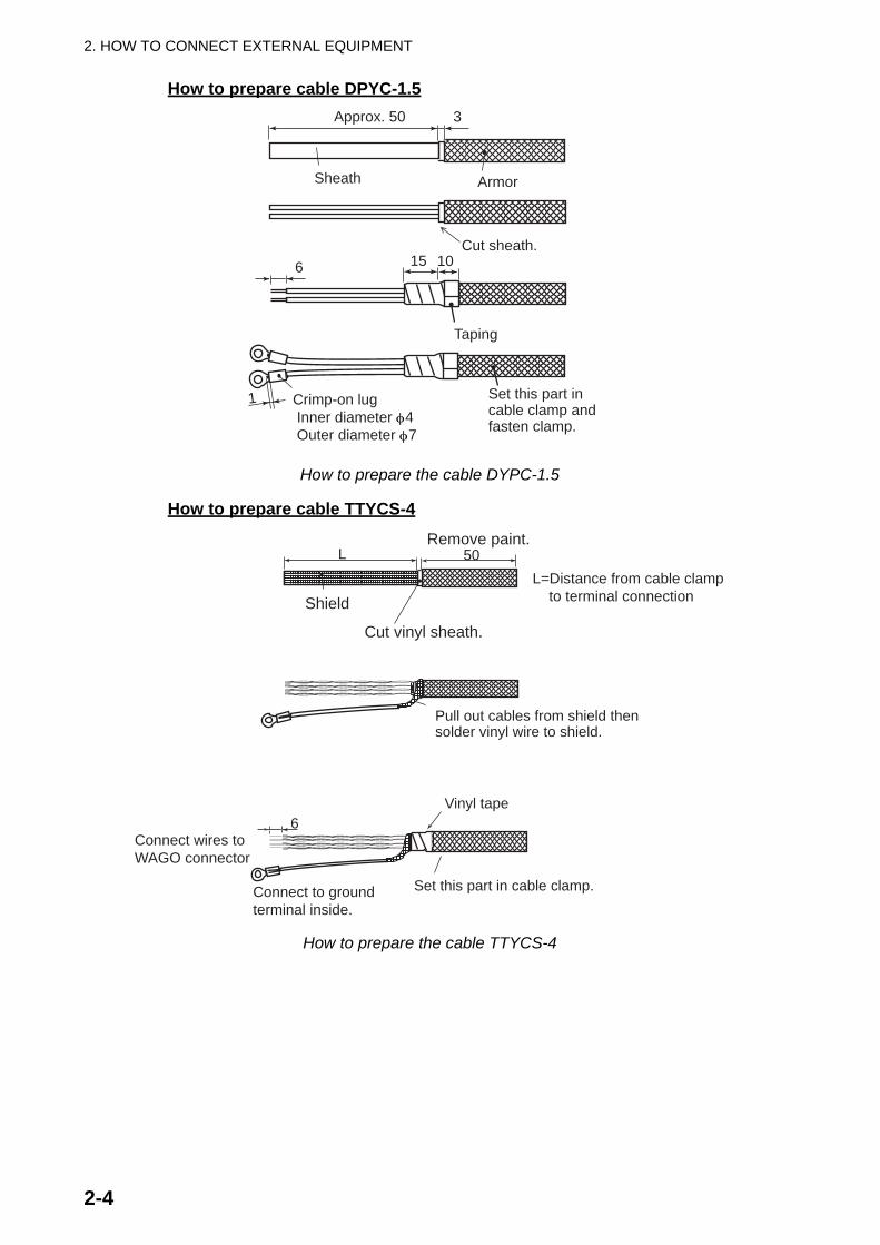
How to prepare cable DPYC-1.5
How to prepare the cable DYPC-1.5
How to prepare cable TTYCS-4
How to prepare the cable TTYCS-4
Approx. 50 3
6
Armor
Cut sheath.
Taping
Sheath
15 10
1 Crimp-on lug Inner diameter φ4 Outer diameter φ7
Set this part incable clamp andfasten clamp.
L
6
50
Shield
Remove paint.
Cut vinyl sheath.
Pull out cables from shield thensolder vinyl wire to shield.
Vinyl tape
Set this part in cable clamp.
L=Distance from cable clamp to terminal connection
Connect to groundterminal inside.
Connect wires toWAGO connector

2. HOW TO CONNECT EXTERNAL EQUIPMENT
2-5
How to connect wires to a WAGO connector
How to connect wires to a WAGO connector
2.2 AC-DC Power Supply
Procedure1. Twist core.2. Set terminal opener as above and push.3. Insert core into hole.4. Release terminal opener.5. Pull wire to confirm it is correctly inserted.
Terminal opener
WAGO connnectorWire
Twist
Push
AC-DC POWER SUPPLYPR-240
Ground Wire (protective)IV-2sq
DPYC-1.5, 2 pcs.24 VDC OUT�
BR-1010BR-1020
DPYC-2.5� 24 VDC IN
MPYC-2
DPYC-1.5100/220 VAC IN �
Ship’s switchboard Connect to batteryvia ship’s mains
� AC FAIL OUTPROCESSORUNIT BR-1020TB31
2. HOW TO CONNECT EXTERNAL EQUIPMENT
2-6
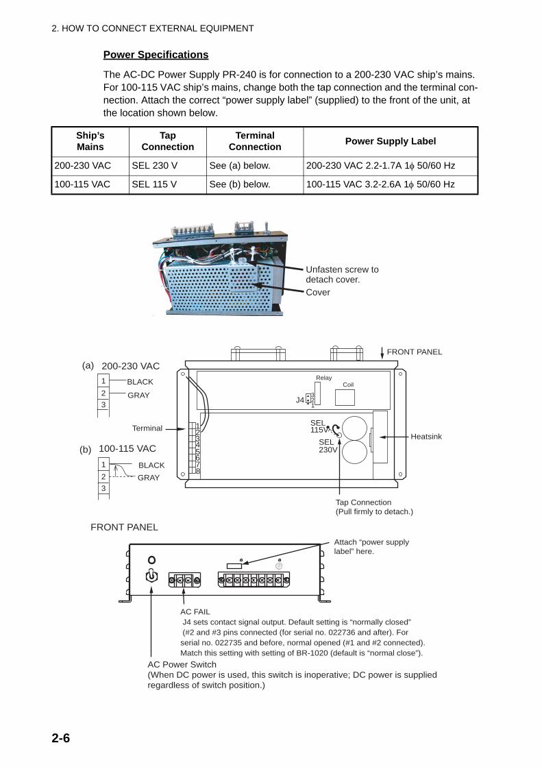
Power Specifications
The AC-DC Power Supply PR-240 is for connection to a 200-230 VAC ship’s mains. For 100-115 VAC ship’s mains, change both the tap connection and the terminal con-nection. Attach the correct “power supply label” (supplied) to the front of the unit, at the location shown below.
Ship’sMains
TapConnection
TerminalConnection Power Supply Label
200-230 VAC SEL 230 V See (a) below. 200-230 VAC 2.2-1.7A 1φ 50/60 Hz
100-115 VAC SEL 115 V See (b) below. 100-115 VAC 3.2-2.6A 1φ 50/60 Hz
Unfasten screw todetach cover.Cover
12345678
Heatsink
Tap Connection(Pull firmly to detach.)
FRONT PANEL
SEL115V
SEL230V
123
100-115 VAC
123
200-230 VAC
Terminal
(a)
(b)
GRAY
BLACK
GRAYBLACK
Attach “power supplylabel” here.
FRONT PANEL
AC FAIL J4 sets contact signal output. Default setting is “normally closed” (#2 and #3 pins connected (for serial no. 022736 and after). Forserial no. 022735 and before, normal opened (#1 and #2 connected).Match this setting with setting of BR-1020 (default is “normal close”).
AC Power Switch(When DC power is used, this switch is inoperative; DC power is supplied regardless of switch position.)
CoilRelay
3
12J4
2. HOW TO CONNECT EXTERNAL EQUIPMENT
2-7
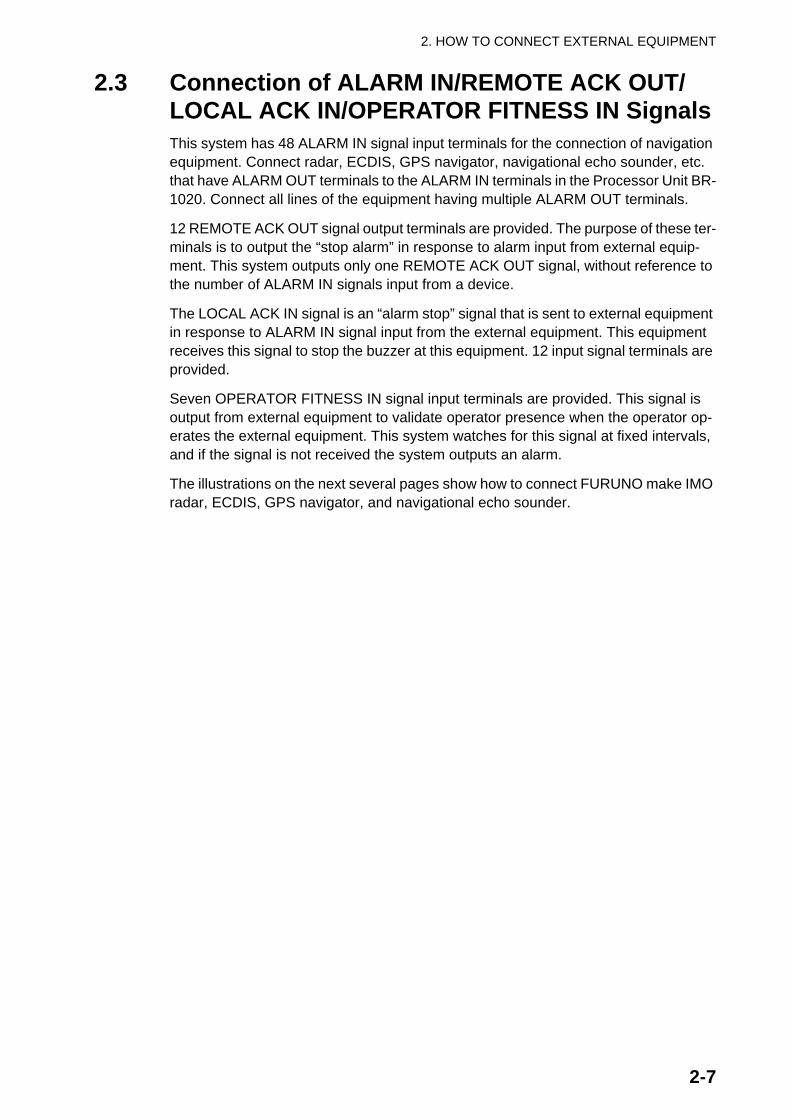
2.3 Connection of ALARM IN/REMOTE ACK OUT/LOCAL ACK IN/OPERATOR FITNESS IN SignalsThis system has 48 ALARM IN signal input terminals for the connection of navigation equipment. Connect radar, ECDIS, GPS navigator, navigational echo sounder, etc. that have ALARM OUT terminals to the ALARM IN terminals in the Processor Unit BR-1020. Connect all lines of the equipment having multiple ALARM OUT terminals.
12 REMOTE ACK OUT signal output terminals are provided. The purpose of these ter-minals is to output the “stop alarm” in response to alarm input from external equip-ment. This system outputs only one REMOTE ACK OUT signal, without reference to the number of ALARM IN signals input from a device.
The LOCAL ACK IN signal is an “alarm stop” signal that is sent to external equipment in response to ALARM IN signal input from the external equipment. This equipment receives this signal to stop the buzzer at this equipment. 12 input signal terminals are provided.
Seven OPERATOR FITNESS IN signal input terminals are provided. This signal is output from external equipment to validate operator presence when the operator op-erates the external equipment. This system watches for this signal at fixed intervals, and if the signal is not received the system outputs an alarm.
The illustrations on the next several pages show how to connect FURUNO make IMO radar, ECDIS, GPS navigator, and navigational echo sounder.
2. HOW TO CONNECT EXTERNAL EQUIPMENT
2-8
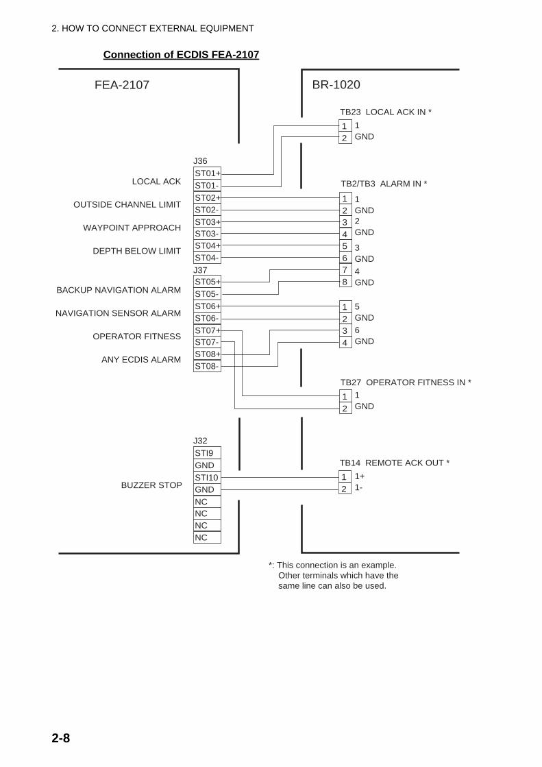
Connection of ECDIS FEA-2107
ST01+ST01-ST02+ST02-ST03+ST03-ST04+ST04-
J36
ST05+ST05-ST06+ST06-ST07+ST07-ST08+ST08-
J37
LOCAL ACK
OUTSIDE CHANNEL LIMIT
WAYPOINT APPROACH
DEPTH BELOW LIMIT
BACKUP NAVIGATION ALARM
NAVIGATION SENSOR ALARM
OPERATOR FITNESS
ANY ECDIS ALARM
12345678
1234
12
TB2/TB3 ALARM IN *
TB27 OPERATOR FITNESS IN *
12
TB23 LOCAL ACK IN *1GND
1GND2GND
3GND4GND
5GND6GND
12
TB14 REMOTE ACK OUT *STI9GNDSTI10GNDNCNCNCNC
J32
1GND
1+1-BUZZER STOP
BR-1020FEA-2107
*: This connection is an example. Other terminals which have the same line can also be used.

2. HOW TO CONNECT EXTERNAL EQUIPMENT
2-9
Connection of IMO radar FAR-2107
FAR-2107 Series
21436587
21
12
TB2 ALARM IN *
TB27 OPERATOR FITNESS IN *
GND1GND2
GND3
GND4
GND1
1+1-
BR-1020
123456789101112
J612
ALARM1_0ALARM1_1ALARM2_0ALARM2_1ALARM3_0ALARM3_1
OPERATOR FITNESSOPERATOR FITNESS
EXT_ALM_ACK_NGND
SYS_FAIL_HSYS_FAIL_C
P
P
P
P
P
P21
1GND
TB14 REMOTE ACK OUT *
TB23 LOCAL ACK IN *
TTYCS-7
*1 *2 *3 Set on menu of FAR-2107.*1 MENU / ALARM / 6 ALARM OUT to select alarm to output.*2 MENU / ALARM / 7 ALARM OUT to select alarm to output.*3 MENU / ALARM / 8 ALARM OUT and select ALARM ACK OUT.*4 MENU / ALARM / 9 ALARM OUT and select OPERATOR FITNESS.(*1 and *2 are normal close signals;*3 and *4 are normal open signals.)
*1
*2
*3
*4
*: This connection is an example. Other terminals which have the same line can also be used.
2. HOW TO CONNECT EXTERNAL EQUIPMENT
2-10
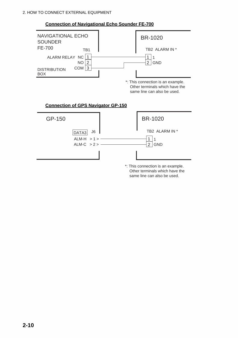
Connection of Navigational Echo Sounder FE-700
Connection of GPS Navigator GP-150
12
TB2 ALARM IN *
1GND
BR-1020NAVIGATIONAL ECHOSOUNDERFE-700
123
TB1
NCNO
COM
*: This connection is an example. Other terminals which have the same line can also be used.
ALARM RELAY
DISTRIBUTIONBOX
12
TB2 ALARM IN *
1GND
BR-1020GP-150
J6
ALM-H > 1 >ALM-C > 2 >
DATA3
*: This connection is an example. Other terminals which have the same line can also be used.

3-1
3. HOW TO SET AND CHECK THE SYSTEMThis chapter shows you how to set the system according to the equipment connected. To make the procedure as easy as possible, an Excel file is used. The Excel file is downloaded from the internet to a PC. The installer enters the settings in the Excel file then uploads the contents of the file to this system. The Excel file can be used again to set this bridge alarm system on another ship.
You can set the system from the Bridge Panel, but that method takes longer than if you use the Excel file. After you have uploaded the contents of the Excel file to the Bridge Panel, you can make small adjustments from the Bridge Panel.
The system accepts 48 channels of ALARM IN signals. These channels are connect-ed to the terminals TB2-TB13 in the Processor Unit. Connect the channels in terminals and write down channel order to prevent confusion, following the interconnection dia-gram. For example, connect the channel no. 1 to #1/2 of TB2 and the channel no. 48 to #7/8 of TB13. Connect other signals and the Cabin Panels according to the inter-connection diagram.
To connect an IAS, see the instructions of the manufacturer of the IAS to set the Mod-bus. (Modbus is the communications protocol used by the IAS.)
3.1 How to Set and Connect the PC for MaintenancePC
• Prepare a laptop PC that meets the requirements shown below.• OS: English or Japanese version Windows XP, or Windows Vista (32 bit)• Microsoft Excel: Excel 2000 or higher (English or Japanese version)• Serial port (If there is no serial port on the laptop, use a serial USB converter
cable (driver).• Set the IP of the PC as shown below.
• IP address: 10.0.0.xxx (xxx=any value except 1, 2 or 3)The IP addresses of the bridge alarm equipment areBR-1010: 10.0.0.1, No.1 BR-1020: 10.0.0.2, No.2 BR-1020: 10.0.0.3
• Subnet mask: 255.255.255.0If you change the IP address on this file, the upload and download connection points change. See Network sheet on page 3-21 for information.
Excel file
The Excel files to use to set this system are on the FURUNO WEB SERVICE. Access this website and download the following two files:
• BR1010CONF.xls• BR1020CONF.xls
Note: These files contain macro functions. When you open the files, make sure you activate the macro functions.
3. HOW TO SET AND CHECK THE SYSTEM
3-2
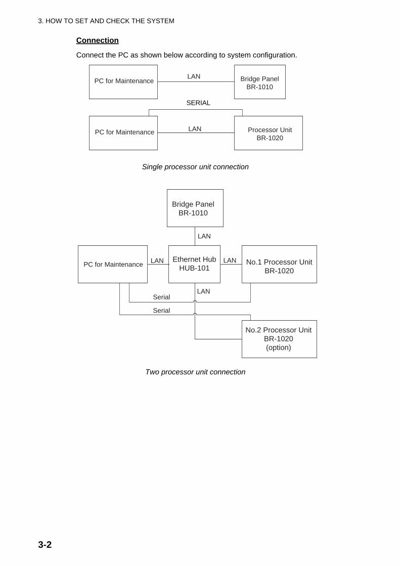
Connection
Connect the PC as shown below according to system configuration.
Single processor unit connection
Two processor unit connection
SERIAL
PC for Maintenance
PC for Maintenance
LAN
LAN
Bridge PanelBR-1010
Processor UnitBR-1020
PC for Maintenance
Serial
Ethernet HubHUB-101
Bridge PanelBR-1010
No.1 Processor UnitBR-1020
No.2 Processor UnitBR-1020(option)
Serial
LAN
LAN
LAN
LAN

3. HOW TO SET AND CHECK THE SYSTEM
3-3
3.2 Settings for Bridge Panel BR-1010The setting data to be uploaded from the PC to the BR-1010 are as shown below.
Setting procedure
The procedure shown below shows how to do all settings collectively. (You can make small adjustments from the BR-1010.)
Note: Before you do this procedure, write down the connections (terminal number, name of equipment connected, signal name) made in the Processor Unit. Use the list at the back of this manual to record this data. Refer to the list to do this procedure.
1. Connect the BR-1010 to the PC as shown in the illustration on page 3-2.2. Open the Definition FIle Update & Backup screen from the BR-1010 as follows:
1) Press the BRILL key while you press the ACK key to turn on the BR-1010. The window below appears, where you are asked to enter the password.
2) Press the up, down, left and right arrows on the Cursor pad followed by the LIST and ESC keys. This is the password to open the Maintenance Mode menu.
Note: If the password is wrong you are asked to turn off the power. Press the BRILL key for more than 10 seconds to turn off the power. Redo the procedure from step 1.
PC for Maintenance Bridge PanelBR-1010
LAN
Check, results
Settings- Alarm/Definition file update, backup- Network settings- Modbus settings, etc.
Enter Password

3. HOW TO SET AND CHECK THE SYSTEM
3-4
This is the Maintenance Mode menu.
3) Press the up or down arrow to select Definition File Update & Back-up then press the ENTER key.
3. Open the Excel file BR1010CONF from the PC.
Maintenance Mode
Self Test Menu
Definition File Update & Back-up
Factory Default
Press [BRILL] key for 10 seconds to power off.
Definition File Update & Back-up
Press [ESC] to exit.
Connecting to Maintenance PC

3. HOW TO SET AND CHECK THE SYSTEM
3-5
4. Open the Config sheet then click the Upload & Download button on the sheet to show the following display.
5. Confirm that the IP address for the BR-1010 is 10.0.0.1. Click the Download but-ton to download the current settings (default values).A bar moves to the right as the download progresses and the message “Com-plete” appears when the download is completed.
6. Set each of the 10 sheets according to the equipment in the system. See the next section for how to enter the values.
7. After you have entered all settings, reopen the Config sheet and click the Upload & Download button.
Config sheet8. Check that the IP address is correct then click the Upload button to upload the
data to the BR-1010.
Click here

3. HOW TO SET AND CHECK THE SYSTEM
3-6
9. Confirm that the data is uploaded to the BR-1010.The yellow progress bar moves to the right as the upload progresses. The mes-sage “Complete” appears when the upload is completed.At the Bridge Panel, the indication at the screen center changes from “Now Writ-ing” to “Connecting to Maintenance PC” when the upload is completed.
10.At the PC, select a name for the updated definition file and save the file.Select a name that is easy to remember, for example, name of ship. If you are set-ting up for several ships, save a file under the name of each ship.
11.Press the BRILL key more than 10 seconds on the BR-1010 to turn off the power. Disconnect the PC from the BR-1010.
Definition File Update & Back-up
Now Writing.
Definition File Update & Back-up
Press [ESC] to exit.
Connecting to Maintenance PC

3. HOW TO SET AND CHECK THE SYSTEM
3-7
[BR-1010 SETTINGS]
This paragraph describes the settings on each sheet in the Excel file.
Channel sheet
The Channel sheets set the input and output channels of the Processor UnitBR-1020.
1. Logical ChannelLogical channel. Do not change the setting.
2. Digital/ModbusSelect to use contact signal or Modbus signal.0: Contact signal (digital channel)1: ModbusAdjustment is normally not required.
3. HOW TO SET AND CHECK THE SYSTEM
3-8
3. IN/OUTSelect the function of the signal, input or output.0: Input1: OutputAdjustment is normally not required.
4. Processor Unit No. (Same as “Input Unit” on the Alarm List editing screen)For contact signal (digital channel), select either the standard BR-1020 or the optional BR-1020. -1: Modbus (For no use) 1: Standard supply BR-1020 2: Optional supply BR-1020Adjustment is normally not required. (The default setting is as follows:1, AL001-AL048 (for standard BR-1020), -1, AL049-AL096 (for Modbus), 2, AL097-AL144 (optional BR-1020), -1, AL145-AL-192 (for Modbus)
5. DIgital Channel (Same as Channel Number/Modbus Address on the Alarm List editing screen)Set input channel number of the BR-1020. Adjustment is normally not required.
6. Modbus Address (Input) (Same as “Channel Number/Modbus” Address on Alarm List editing screen.)Set Modbus address at input side (alarm at IAS side, etc.). Range: 1-64Note: Adjustment is normally not required, but consult with the IAS maker.
7. Modbus Address(Output)Set Modbus address at output side (alarm at BR-1000, etc.)Range: 65-128

3. HOW TO SET AND CHECK THE SYSTEM
3-9
Group sheet
1. Group NumberSet group number. Adjustment is normally not required.
2. Local ACK INSet Local ACK IN group. Adjustment is normally not required.
3. Remote ACK OUTSet Remote ACK IN group. Adjustment is normally not required.
Group sheet

3. HOW TO SET AND CHECK THE SYSTEM
3-10
CPanel sheet
The CPanel sheet has settings for the Cabin Panels. Before you do this procedure, record the terminal numbers (TB32-TB41) where the Cabin Panels are connected in the Processor Unit. The Cabin Panel connected to TB32 has the name “CP001” on this sheet. The Cabin Panel connected to TB41 has the name “CP010”.
CPanel sheet1. Panel Number2. Cabin Panel LED(Alarm)3. Cabin Panel LED(Duty)4. Cabin Panel Buzzer5. IAS Panel Control6. Cabin Panel Test Channel
Do not change the settings of items 1-6.7. Panel Type
Set the type of each Cabin Panel.0: Cabin Panel fitted in Captain’s room1: Cabin Panel installed in the quarters of the officer(s) selected as back-up officer candidate. The Captain of the ship selects which officer is to be the back-up officer.2: Cabin Panel installed in public areas - lobby, dining room, leisure room, etc.
8. Panel NameEnter the name for each Cabin Panel. Use title of person or name of room. A max-imum of 10 alphanumeric characters can be used for panel name.

3. HOW TO SET AND CHECK THE SYSTEM
3-11
TPanel sheet
The TPanel sheet sets the Timer Reset Panel. Do not change the settings on this sheet.
TPanel sheet

3. HOW TO SET AND CHECK THE SYSTEM
3-12
Alarm sheet
The Alarm sheet sets the alarms.
1. Tag NumberDo not change this setting.
2. Channel NumberGive tag numbers to alarm logical channels. Adjustment is normally not required.
3. Alarm Text (Same as “Alarm Text” on the Alarm List editing screen.)Set the name of each alarm. You can use alphanumeric characters, and the name can have a maximum of 32 characters including spaces.Give Tag Numbers (Channel Numbers) according to terminal location on the Pro-cessor Unit BR-1020 as follows. Enter the name of the alarm connected to TB #1/2 in the input box for Tag Number 1. - TB2 #1/2: Tag Number 1 (Channel Number AL001) - TB2 #3/4: Tag Number 2 (Channel Number AL002) - TB13 #7/8: Tag Number 48 (Channel Number AL048)

3. HOW TO SET AND CHECK THE SYSTEM
3-13
If the No.2 processor unit is installed, enter tag numbers as shown below. - No. 2 BR-1020 TB2 #1/2: Tag Number 97 (Channel Number AL097) - TB2 #3/4: Tag Number 98 (Channel Number AL098)Enter a name for the alarm that clearly identifies the type of alarm. These names appear on the Bridge Alarm Display and the Auto Alarm Pop-up Display.Example: No. 1 Radar CPA/TCPA/GZ No. 2 Radar System Fail No. 1 GPS off-track
4. Group Number (Same as “Group Number” on the Alarm List editing screen.) Col-lect like alarms into a group.Range: 1-25, 25 is for Modbus.Examples:• Assign the four lines of alarm signals from the No. 1 radar that are connected to
TB2 in the No. 1 processor unit to Group 1.• Assign the four lines of alarm signals from the No. 2 radar that are connected to
TB3 in the No. 1 processor unit to Group 2.• Assign the eight lines of alarm signals from the ECDIS that are connected to
TB4 and TB5 to Group 3.• Assign the four lines of alarm signals from a GPS navigator that are connected
to #1/2 of TB6 to Group 4.5. Alarm Priority/Status
Assign priority to each alarm. Check with ship personnel to set priority. Priority appears on the Bridge Alarm Display and the Auto Alarm Pop-up Display.0: Emergency1: Urgency2: Primary3: Secondary
6. Type of SignalSet the type of contact signal for each alarm. Set according to equipment con-nected.0: AL Open (Contact signal opens when an alarm is generated - NC.)1: AL Close (Contact signal closes when an alarm is generated - N0.)2: Modbus
7. Active/InactiveActivate or deactivate each alarm. (The Bridge Panel ignores an alarm set as inactive.)0: Inactive1: Active
8. Alarm ExtendedExtend or don’t extend an alarm at the BR-1000 if the BUZ STOP and ACK keys are not operated after a device is restored to normal operation after generating an alarm.0: OFF (Alarm is not extended. Alarm is canceled at the BR-1000 after the alarm is cleared from a device.1: ON (Alarm is extended. Alarm is sent to the Cabin Panels (depending on mode) if the BUZ STOP and ACK keys are not operated.)

3. HOW TO SET AND CHECK THE SYSTEM
3-14
9. Alarm TypeEnable or disable the repeat alarm for Modbus.When a “normal” alarm is generated and the repeat alarm address changes, the alarm changes to a repeat alarm. (Not related to contact signal.)0: Normal Alarm (No repeat alarm)1: Repeat Alarm (With repeat alarm)Note: For Modbus. Consult with the IAS maker.
10.Repeat Alarm Channel NumberIf the Alarm Type is Repeat Alarm, the repeat alarm is generated when the address of the corresponding logical channel changes.
11.VDROutput or don’t output the ALR sentence to a VDR when related alarm is gener-ated.0: Disable (no output)1: Enable (output)

3. HOW TO SET AND CHECK THE SYSTEM
3-15
Menu sheet
The Menu sheet has settings for the Administrator menu and the Service menu. The Administrator menu has items that can be adjusted by ship authorities (like the Cap-tain) according to navigation status. The installer can keep the default settings. See the BR-1000 Operator’s Manual for information about the Administrator menu.
[Administrator menu]1. Mode Select
Set the operating mode.0: Harbour Mode1: Attended Mode2: One-Man Mode
2. Back-up Officer SelectSelect the back-up officer (Range: 0-9).0: Cabin Panel 11: Cabin Panel 2 . . .9: Cabin Panel 10
ACPower Fail

3. HOW TO SET AND CHECK THE SYSTEM
3-16
Select the Cabin Panels that are set as “1 Back-up Officer” with the item “Panel Type” on the CPanel sheet.
3. Captain Back-upSet if the Cabin Panel in the Captain’s room is to give the audible alarm in the 2nd phase of an alarm or not.0: DIsable (no audible alarm)1: Enable (audible alarm sounds)
4. Watch Time Interval SelectSet the watch time interval.Range: 3-12 (m)
5. All Back-up Officer Call IntervalSelect the time interval between the end of the 2nd phase and the start of the 3rd phase. The time unit is seconds.0: 901: 1202: 1503: 180
6. Use Key BeepA beep sounds when a key is operated. This beep can be turned on or off.0: Disable (no beep)1: Enable (beep)
[System Setting menu]
1. IMO/DNV Mode SelectSet the specification for the timing of watch alarm generation, IMO or DNV, See Chapter 1 in the Operator’s Manual for information about this setting.0: IMO (International Maritime Organization)1: DNV (Det Norske Veritas, Norwegian classification society)
2. Buzzer TypeSet the buzzer type for continuous or intermittent.0: Continuous1: Intermit
3. Bridge Panel Buzzer ToneSet the buzzer frequency for the buzzer at the BR-1010.Range: 2100-2300 (Hz)In 10 Hz increments. Adjustment is normally not required.
4. No. 2 Processor Unit ConnectionSet whether the optional BR-1020 is connected or not.0: Disable (no connection)1: Enable (connected)
3. HOW TO SET AND CHECK THE SYSTEM
3-17
5. Use External SirenUse an external siren or not.0: DIsable (don’t use)1: Enable (use)
6. IAS ConnectionSet whether IAS is connected or not.0: Disable (no connection)1: Enable (connected)
7. AC Power FailSet the #5-#6 terminals of TB31 in the processor unit as “normally closed” or “nor-mally open”.0: Normally closed1: Normally open
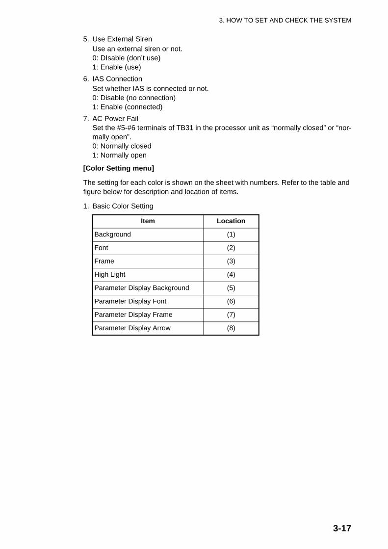
[Color Setting menu]
The setting for each color is shown on the sheet with numbers. Refer to the table and figure below for description and location of items.
1. Basic Color Setting
Item Location
Background (1)
Font (2)
Frame (3)
High Light (4)
Parameter Display Background (5)
Parameter Display Font (6)
Parameter Display Frame (7)
Parameter Display Arrow (8)

3. HOW TO SET AND CHECK THE SYSTEM
3-18
2. Bridge Alarm Color Setting
Item Location
Bridge Alarm Display Page (1)
“BRIDGE ALARM” Font (2)
WATCHALARM
MODEONEMAN
BACK-UPC/OFFICER
TIME INTERVAL
3 MIN
BRIDGEALARM
Description Set
B a s ic C o lo r S e t t in g
B a c k g r o u n d
F o n t
F r a m e
H ig h L ig h t
P a r a m e t e r D is pla y - B a c k g r o u n d
- F o n t
- F r a m e
- A r r o w
(4) High Light(2) Font
(3) Frame(1) Background
C a pta in B a c k-up
Dis a ble
(6) Parameter Display Font
(8) Parameter Display Arrow(5) Parameter Display Background (4) High Light
(7) Parameter Display Frame
WATCHALARM
MODEONEMAN
BACK-UPC/OFFICER
TIME INTERVAL
3 MIN
BRIDGEALARM
No.1 Radar Sys Fail
No.2 Radar Sys Fail
No.3 Radar Sys Fail
No.1 Radar CPA/TCPA/GZ
No.2 Radar CPA/TCPA/GZ
No.3 Radar CPA/TCPA/GZ
No.1 RADAR System Error
No.2 RADAR System Error
Description
Secondary
Priority
001
002
003
004
005
006
007
008
Tag
Secondary
Secondary
Urgency
Urgency
Urgency
Secondary
Secondary
1 2 3 4 5 6 7 8 9 10 11 12
(1) Bridge Alarm Display Page
(2) “BRIDGE ALARM” Font

3. HOW TO SET AND CHECK THE SYSTEM
3-19
3. “WATCH ALARM” Color Setting
4. “MODE” Color Setting
Item Location
“WATCH ALARM” Font (1)
Item Location
“MODE” Font (1)
Parameter Font (2)
“MODE” Background (3)
“ATTEND”, “ONEMAN” Background (4)
WATCHALARM
MODEONEMAN
BACK-UPC/OFFICER
BRIDGEALARM
BRIDGE ALARM SYSTEM BR-1000
NO ALARM
TIME INTERVAL
3 MIN
(1) “WATCH ALARM” Font
WATCHALARM
MODEONEMAN
BACK-UPC/OFFICER
BRIDGEALARM
BRIDGE ALARM SYSTEM BR-1000
NO ALARM
TIME INTERVAL
3 MIN
(3) “MODE” Background
(4) “ATTEND”, “ONEMAN” Background
(1) “MODE” Font
(2) Parameter Font

3. HOW TO SET AND CHECK THE SYSTEM
3-20
5. “BACK-UP” Color Setting
6. “TIME INTERVAL” Color Setting
Item Location
“BACK-UP” Font (1)
Parameter Font (2)
Background (3)
Item Location
“TIME INTERVAL” Font (1)
Parameter Font (2)
Background (3)
WATCHALARM
MODEONEMAN
BACK-UPC/OFFICER
BRIDGEALARM
BRIDGE ALARM SYSTEM BR-1000
NO ALARM
TIME INTERVAL
3 MIN
(1) “BACK-UP” Font(2) Parameter Font(3) Background
WATCHALARM
MODEONEMAN
BACK-UPC/OFFICER
BRIDGEALARM
BRIDGE ALARM SYSTEM BR-1000
NO ALARM
TIME INTERVAL
3 MIN
(1) “TIME INTERVAL” Font
(2) Parameter Font(3) Background

3. HOW TO SET AND CHECK THE SYSTEM
3-21
[Test Mode menu]
The test mode checks the system for proper operation. See section 3.4 for informa-tion.
1. Test Mode ON/OFFTurn test mode ON/OFF.0: OFF (normal operation)1: ON
2. Time Visual/Audible AlarmSet the time interval for the Prewarning and 2nd phase of the watch alarm to use in the test mode.Range: 5-14 (s)
3. Watch Time IntervalSet the watch time interval to use in the test mode.Range: 10-30 (s)
4. All Back-up Officer Call IntervalSet the time interval to use between the 2nd and 3rd phases in the test mode.Range: 10-30 (s)
5. Buzzer SilenceSound or don’t sound the buzzer in the test mode.0: Disable (no buzzer)1: Enable (buzzer sounds)
Network sheet
The network sheet sets the network. These settings cannot be entered or changed from the Bridge Panel.
1. Bridge Panel IP AddressEnter the IP address of the BR-1010. Adjustment is normally not required.
2. No.1 Processor Unit IP Address3. No.2 Processor Unit IP Address
Set the IP address of the No.1 and No.2 Processor Unit. (These are settings for the bridge panel, so it may be necessary to change the setting for the No. 2 Pro-cessor Unit.)Adjustment is normally not required.
4. Subnet MaskSet the subnet mask. Adjustment is normally not required.

3. HOW TO SET AND CHECK THE SYSTEM
3-22
Modbus sheet
Modbus is the communications protocol used between the IAS and this system. These settings cannot be entered or changed from the Bridge Panel.
Note: For Modbus; consult with the IAS maker. The BR-1000 cannot be used with an IAS unless settings are compatible with one another.
1. Modbus ModeSet the Modbus mode.0: RTU1: ASCII
2. Range of IAS Address(Start)Set the start address at the IAS side. Alarm data generated at the IAS is written into the IAS address at the IAS side.Range: 1-64Adjustment is normally not required, but may be required depending on the make of the IAS.
3. Range of IAS address(End)Set the end address at the IAS side.Range: 1-64Adjustment is normally not required, but may be required depending on the make of the IAS.
4. Range of BR-1000 Address(Start)Set the start address at the BR-1000 side. Generated alarm data is written into the BR-1000 address at the BR-1000 side.Range: 65-128Adjustment is normally not required, but may be required depending on the make of the IAS.
5. Range of BR-1000 Address(End)Set the end address at the BR-1000 side.Range: 65-128Adjustment is normally not required, but may be required depending on the make of the IAS.
3. HOW TO SET AND CHECK THE SYSTEM
3-23
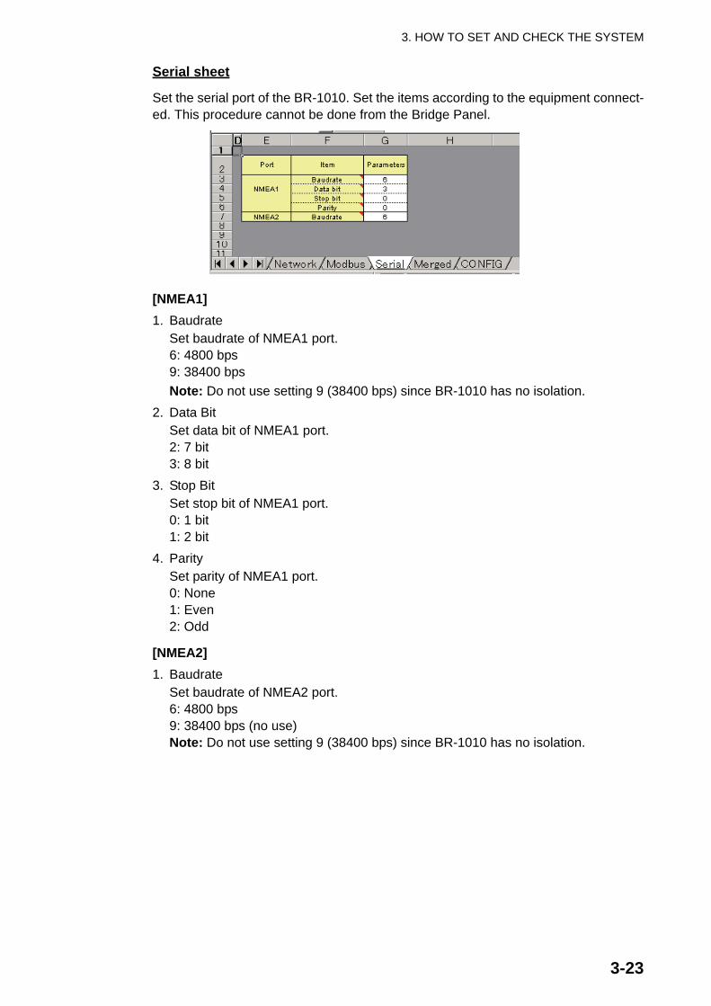
Serial sheet
Set the serial port of the BR-1010. Set the items according to the equipment connect-ed. This procedure cannot be done from the Bridge Panel.
[NMEA1]1. Baudrate
Set baudrate of NMEA1 port.6: 4800 bps9: 38400 bpsNote: Do not use setting 9 (38400 bps) since BR-1010 has no isolation.
2. Data BitSet data bit of NMEA1 port.2: 7 bit3: 8 bit
3. Stop BitSet stop bit of NMEA1 port.0: 1 bit1: 2 bit
4. ParitySet parity of NMEA1 port.0: None1: Even2: Odd
[NMEA2]1. Baudrate
Set baudrate of NMEA2 port.6: 4800 bps9: 38400 bps (no use)Note: Do not use setting 9 (38400 bps) since BR-1010 has no isolation.

3. HOW TO SET AND CHECK THE SYSTEM
3-24
Merged sheet
Settings for a Merged System. A Merged System uses the Cabin Panels of an IAS to forward the alarms generated at the BR-1000. (The Cabin Panels of the BR-1000 are not installed.) Consult with the IAS maker.Range: 65-128
Config sheet
The Config sheet shows the software version of the BR-1010. Modification of the con-tents of this sheet is not necessary. Use the sheet to upload and download data.

3. HOW TO SET AND CHECK THE SYSTEM
3-25
3.3 Settings for Processor Unit BR-1020Connect the PC to the BR-1020 as shown below. Do the procedure below to update the BR-1020.
How to update the BR-1020
This section shows you how to update the BR-1020. This is the only procedure avail-able to update the BR-1020.
1. Connect the PC to the BR-1020 and turn on the Bridge Panel.2. Open the Maintenance Excel file BR1020CONF from the PC.3. Open the Config sheet and click the Upload & Download button to show the
BR-1000 Maintenance window.
4. Check that the IP address for the BR-1020 is correct then click the Download but-ton.
5. Change the settings on the Processor Unit sheet. See “Description of settings for BR-1020” on the next page.
Software update
LAN
Serial
PC for Maintenance Processor UnitBR-1020
Check, results
Settings- Network settings- Serial communications settings- Modbus settings
Serialport
Serialport

3. HOW TO SET AND CHECK THE SYSTEM
3-26
6. After you have set all items, reopen the Config sheet and click the Upload & Download button.
7. Check that the IP address shown in the window is correct.
8. Click the Upload button to upload setting data. When the uploading is completed, the message “Complete” appears.
9. Give a name to the updated definition file and save the file. Select a name that is easy to remember; for example, name of ship.
10.Disconnect the PC from the BR-1020. Open the BR-1020 then push the Reset button inside.
RESET button S3
1 2 3 4
ON

3. HOW TO SET AND CHECK THE SYSTEM
3-27
Description of settings for BR-1020
Processor Unit sheet
[Network]
Enter network settings here.
1. IP AddressSet the IP address for the BR-1020. Adjustment is normally not required.
2. Subnet maskSet the subnet mask for the BR-1020. Adjustment is normally not required.
[UART1], [UART2]
UART1 and UART2 are settings for the serial lines for terminals TB-42 and TB-43 in the Processor Unit.
1. Modbus(RTU) / Modbus(ASCII) / NMEASelect a Modbus mode or NMEA for UART.0: Modbus(RTU)1: Modbus(ASCii)2: NMEA (no use)
2. BaudrateSet baudrate of UART.0: DIPSW1: 4800 bps2: 9600 bps3: 19200 bps4: 38400 bpsFor 0(DIPSW), see the table below to set baud rate with DIP switch S3, inside the BR-1020. See page 3-26 for the location of S3.
S3 #1 S3 #2 Baudrate(bps) for TB-42 S3 #3 S3 #4 Baudrate(bps)
for TB-43
0 0 4800 0 0 4800
0 1 9600 0 1 9600
1 0 19200 1 0 19200
1 1 19200 1 1 19200
H
3. HOW TO SET AND CHECK THE SYSTEM
3-28
3. Data BitSet data bit of UART.0: 7 bit1: 8 bit
4. Stop BitSet stop bit of UART.0: 1 bit1: 2 bit
5. ParitySet parity of UART.0: None1: Even2: Odd
[Modbus]
1. Slave AddressSet slave address.Range: 1-247
2. IAS Address(Start)Set the start address at the IAS side. (Range: 1-64)Adjustment is normally not required, but may be required depending on the make of the IAS.If change is necessary, set this address the same as that for “Range of IAS Adddress(Start)” at the BR-1010.
3. IAS address(End)Set the end address at the IAS side. (Range: 1-64)Adjustment is normally not required, but may be required depending on the make of the IAS.If change is necessary, set this address the same as that for “Range of IAS Adddress(End)” at the BR-1010.
4. BR Address(Start)Set the start address at the BR-1000 side. (Range: 65-128)Adjustment is normally not required, but may be required depending on the make of the IAS.If change is necessary, set this address the same as that for “Range of BR Adddress(Start)” at the BR-1010.
5. BR Address(End)Set the end address at the BR-1000 side. (Range: 65-128)Adjustment is normally not required, but may be required depending on the make of the IAS. If change is necessary, set this address the same as that for “Range of BR Adddress(End)” at the BR-1010.

3. HOW TO SET AND CHECK THE SYSTEM
3-29
Config sheet
The Config sheet shows the software version of the BR-1020. Use this sheet to upload and download setting data. Modification of this sheet is not necessary.
After entering all settings, click the Upload & Download button, enter the IP address of the BR-1020 then click the Upload button to upload the setting data.

3. HOW TO SET AND CHECK THE SYSTEM
3-30
3.4 System Operation CheckYou check the system operation from the Test Mode Menu. This method is faster than checking the bridge alarm and watch alarm through normal operation.
Operation with the test mode active
[Bridge alarm]
• The Initial Setting Display and the Alarm List editing screen cannot be opened when a bridge alarm is active.
• Press the BUZ STOP and ACK keys to stop an alarm. The system goes into “Pend-ing” state then you can open the menu. To show the Initial Setting Display, press the ESC key and “Pending Alarm” appears at the screen center. Press the MENU key to show the display. “Pending” means that the buzzer has been stopped and alarm acknowledged, but the cause of the alarm has not yet been removed.
[Watch alarm]
• The Initial Settings Display can be shown when a watch alarm is active.• When a watch alarm is active and the MENU key is pressed, the audible alarm
stops (audible alarms stop even if the alarm is sent to the next stage) and the win-dow for password entry appears.
• The watch timer restarts after a watch alarm is stopped.• If the bridge alarm and watch alarm are generated simultaneously, priority is given
to the bridge alarm. In that case, the Initial Setting Display cannot be opened.
Do the following to check operation. Note that the system returns to the standby dis-play if there is no menu operation in 60 seconds.
1. Press the MENU key, and the message “Enter Password” appears.
WATCHALARM
MODEONEMAN
BACK-UPC/OFFICER
BRIDGEALARM
BRIDGE ALARM SYSTEM BR-1000
NO ALARM
TIME INTERVAL
3 MIN
BRIDGE ALARM SYSTEM BR-RR 1000
NO ALARMEnter Password

3. HOW TO SET AND CHECK THE SYSTEM
3-31
2. Press the up, down, left and right arrow pads on the Cursor pad followed by the LIST and ESC keys. This is the password to open the Service menu.
3. Press the down arrow to select (highlight) Test Mode Menu then press the ENTER key. The values shown in the Set column are those uploaded from the PC.
4. With Test Mode ON/OFF selected, press the ENTER key.
5. Press the right arrow to select ON then press the ENTER key.
6. Press the ESC key to show the following window.
7. Select Yes then press the ENTER key.• To return to the Service Menu without making any changes, select No then press
the ENTER key.• Select Cancel and press the ENTER key to close the window and return to the
Test Mode menu.
WATCHAlarm
MODEONEMAN
BACK-UPC/OFFICER
TIME INTERVAL
3 MIN
BRIDGEAlarm
Color Setting Menu Test Mode Menu
System Setting Menu
Description Set
S e rvic e Menu
Cabin Panel Setting Menu
WATCHALARM
MODEONEMAN
BACK-UPC/OFFICER
TIME INT3 MIN
BRIDGEALARM
Description Set
T es t Mode Menu
OF F
5 s e c 15 s e c
15 s e c Disable
T e s t Mode ON / OFF
> T ime V is ua l / Audio Alarm> Watch Time Interval> All Back-up Offcer Call Interval> Buzzer Silence
OF F
T e s t Mode ON/OFF
ON
T e s t Mode ON/OFF
Do you w a nt to s a ve ?
Y e s N o C a nc e l

3. HOW TO SET AND CHECK THE SYSTEM
3-32
When Yes is selected and the MODE box at the left side of the display shows TEST MODE and the test mode starts.
Note: To stop the test mode, select OFF at step 5 in this procedure, press the ENTER key then do steps 6 and 7. Make sure you quit the test mode by this method.
• The test mode generates the watch alarm faster than the normal method. Check that the Bridge Panel and all Timer Reset Panels and Cabin Panels operate nor-mally. To check the bridge alarm, create a condition that causes an external equip-ment to generate an alarm. Check that all units of the system respond to the alarm. The alarm timing is shown in the illustration below and on the next page.
Watch alarm sequence in test mode
TEST MODEONEMAN
TEST MODEATTENDED
TEST MODEHARBOUR
Watch Time Interval(10-30 s)
Time Visual/AudibleAlarm Alarm setting (5-14 s)
All Back-up Offcer CallInterval (10-30 s)
BRIDGE PANELTIMER RESET PANEL
(incl. watertight type)
Back-up nav. officer quartersand CABIN PANELS
in all public areas
All nav. officer quartersand CABIN PANELS
in all public areas
Visual ALM* + Audible ALM
Visual ALM (lighting)+ Audible ALM
Visual ALM (lighting)+ Audible ALM
BUZZER STOP � ACKTimer starts
Timerreset
2nd stage
3rd stage
NO BUZZER STOP � NO ACKAlarm forwarded
- TIMER RESET- OPERATOR FITNESS- ACK
Visual ALM*
Visual ALM (lighting)+ Audible ALM
Visual ALM*+ Audible ALM
If none of the above,alarm is forwarded
*Red flashing at Bridge Panel, yellow flashing at Timer Reset Panel
1ststage
After specifiedinterval elapses
Prewarning

3. HOW TO SET AND CHECK THE SYSTEM
3-33
Bridge alarm sequence in test modeThe Test Mode menu has various alarm-related parameters that can be changed. Ad-justment is not normally required.
Menu item: Time Visual / Audible Alarm (sec)
Set the time interval for the visual and audible alarms in the test mode.
The range is 5-14 (s). Use the left or right arrow to set.
Menu item: Watch Time Interval
Set the watch time interval for the test mode.
The setting range is 10-30 (s). The selected interval appears in the TIME INTERVAL box at the lower left corner.
External equipmentgenerates alarm
1st stage
Time Visual/AudibleAlarm setting
(5-14 s)
BRIDGE PANELTIMER RESET PANEL
(incl. watertight type)
Back-up nav. officer quartersand CABIN PANELS
in all public areas
Back-up nav. officer quartersand CABIN PANELS
in all public areas
Visual ALM (flashing) + Audible ALM
Visual ALM (lighting)+ Audible ALM
Visual ALM (lighting)+ Audible ALM
BUZZER STOP � ACK
Timerreset
2nd stage
3rd stage
NO BUZZER STOP � NO ACKAlarm forwarded
Visual ALM (lighting)+ Audible ALM
Visual ALM (red flashing)+ Audible ALM (buzzer)
If NO BUZ STOP � NO ACK,then alarm is forwarded
All Back-up Officer CallInterval (10-30 s)
T ime Visual / Audible Alarm (sec)
5 sec
Wa tc h T ime Inte rva l (sec)
10 sec
3. HOW TO SET AND CHECK THE SYSTEM
3-34
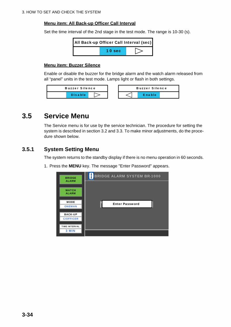
Menu item: All Back-up Officer Call Interval
Set the time interval of the 2nd stage in the test mode. The range is 10-30 (s).
Menu item: Buzzer Silence
Enable or disable the buzzer for the bridge alarm and the watch alarm released from all “panel” units in the test mode. Lamps light or flash in both settings.
3.5 Service MenuThe Service menu is for use by the service technician. The procedure for setting the system is described in section 3.2 and 3.3. To make minor adjustments, do the proce-dure shown below.
3.5.1 System Setting MenuThe system returns to the standby display if there is no menu operation in 60 seconds.
1. Press the MENU key. The message "Enter Password" appears.
All Back-up Officer Call Interval (sec)
10 sec
B uzze r S ile nc e
Dis a ble
B uzze r S ile nc e
E na ble
WATCHALARM
MODEONEMAN
BACK-UPC/OFFICER
BRIDGEALARM
BRIDGE ALARM SYSTEM BR-1000
NO ALARM
TIME INTERVAL
3 MIN
BRIDGE ALARM SYSTEM BR-RR 1000
NO ALARMEnter Password

3. HOW TO SET AND CHECK THE SYSTEM
3-35
2. Press the up, down, left and right arrows on the Cursor pad followed by the LIST and ESC keys. This is the password to open the Service menu.
3. System Setting Menu is selected (highlighted); press the ENTER key.
4. DNV/ IMO Mode Select is selected; press the ENTER key.
5. Press the left or right arrow to select IMO or DNV. See Chapter 1 in the Operator’s Manual for a description of the IMO and DNV modes.
6. Press the ENTER key.7. If required, set other items.
WATCHAlarm
MODEONEMAN
BACK-UPC/OFFICER
TIME INTERVAL
3 MIN
BRIDGEAlarm
Color Setting Menu Test Mode Menu
System Setting Menu
Description Set
S e rvic e Menu
Cabin Panel Setting Menu
WATCHALARM
MODEONEMAN
BACK-UPC/OFFICER
TIME INTERVAL
3 MIN
BRIDGEALARM
DN V / IMO Mode S e le c t
B ridge P a ne l B uzze r T one (Hz)
B uzze r T ype
No.2 Processor Unit Connection
2160Hz
IMO Description Set
No
Continuous
S ys tem S e tting Menu
Use External Siren No
IAS Connection EnableAC Power Fail AL Open
DNV / IMO Mode S e le c t
IMO
DNV / IMO Mode S e le c t
DN V

3. HOW TO SET AND CHECK THE SYSTEM
3-36
8. After you set all items required, press the ESC key to quit. You are asked if you are sure to save the settings.
9. Select Yes then press the ENTER key. Your settings are saved and the Service menu is redisplayed.• To return to the Service Menu without making any changes, select No then press
the ENTER key.• Select Cancel then press the ENTER key to close the window and return to the
Test Mode menu.
Description of System Setting Menu
Menu item Options Function
DNV/ IMO Mode Select
DNV, IMO Select the timing specification of alarmforwarding in the watch alarm.DNV: Det Norske VeritasIMO: International Maritime Organization
Buzzer Type Continuous, Intermit Select buzzer type.Continuous: Continuous buzzerIntermit: Intermittent buzzer
Bridge Panel Buzzer Tone (Hz)
2100-2300 Hz Set the frequency of the buzzer released from the Bridge Panel.
No.2 Processor Unit Connection
Enable, Disable Select whether the No.2 Processor Unit is connected or not.Enable: ConnectedDisabled: Not connected
Use External Siren Enable, Disable Use external siren or not.Enable: Use external siren.Disable: Don’t use external siren.
IAS Connection Enable, Disable Select whether IAS is connected or not.Enable: ConnectedDisable: Not connected
AC Power Fail AL Close, AL Open Set input terminals #5, #6 of TB31 inBR-1020.AL Close: Close, normally openAL Open: Open, normally closed
WATCHALARM
MODEONEMAN
BACK-UPC/OFFICER
TIME INTERVAL
3 MIN
BRIDGEALARM
DN V / IMO Mode S e le c t
B ridge P a ne l B uzze r T one
B uzze r T ype
No.2 Processor Unit Connection
2160Hz
IMO Description Set
No
Continuous
S ys tem S e tting Menu
Use External Siren Disable
DN V/ IMO Mode S e le c t
B ridge P a ne l B uzze r T one
B uzze r T ype
No 2 Processor Unit Connection
2160Hz
IMODescription Set
No
Continuous
S ys tem S etting Menu
Do you w a nt to s a ve?
Y e s N o C a nc e l
IAS Connection Enable
AC Power Fail AL Open

3. HOW TO SET AND CHECK THE SYSTEM
3-37
3.5.2 Cabin Panel Setting MenuThe purpose of this menu is to give names to the Cabin Panels. Record beforehand where the Cabin Panels are connected (TB32-TB41) on the Processor Unit.
1. At the Service menu, select Cabin Panel Setting Menu then press the ENTER key.
2. Cabin Panel 1 is selected; press the ENTER key.
3. Panel Type is selected; press the ENTER key. The panel type selection window appears.
4. Use the left or right arrow to select a type then press the ENTER key.• Captain: For the Cabin Panel installed in the Captain’s room.• Back-up: For the Cabin Panel installed in the sleeping quarters of the backup
officer. Consult with the Captain of the ship to set this item.• Public: For the Cabin Panel installed in a public area.
WATCHALARM
MODEONEMAN
BACK-UPC/OFFICER
TIME INTERVAL
3 MIN
BRIDGEALARM
Cabin Panel 6Cabin Panel 1
Cabin Panel 2
Cabin Panel 3
Cabin Panel 4
Cabin Panel 5
Cabin Panel 7
Cabin Panel 8
Cabin Panel 9
Cabin Panel 10
Cabin Panel Setting Menu
DescriptionDescription
WATCHALARM
MODEONEMAN
BACK-UPC/OFFICER
TIME INTERVAL
3 MIN
BRIDGEALARM
Description Set
C a bin P a ne l 1
Panel Type
Panel Name
Captain
Capt.
P a ne l T ype
C a pta in
P a ne l T ype
P ublic
P a ne l T ype
Back-up

3. HOW TO SET AND CHECK THE SYSTEM
3-38
5. Select Panel Name then press the ENTER key.The Panel Name entry window appears. The names for cabin panels are con-tained in the definition file. If required, you can change the name here.
6. Enter the title of the person who uses the room or the name of the room. Press the ENTER key.The name can have up to 10 alphanumeric characters. See the illustration below for how to enter name.
7. Enter the name for other Cabin Panels if necessary.8. Press the ESC key to close the window.9. Select Yes then press the ENTER key to save settings and return to the Service
menu.
How to enter data
When you open the data input window, a flashing cursor is to right of the enteredalphabet. The keyboard appears together with the text input box and the alphabet “q” is selected (highlighted).
1. Use the Cursor pad on the Bridge Panel to put the cursor on [←] on the keyboard.2. Press the ENTER key. The input cursor moves to the input field.3. Do steps 1 and 2 to set the cursor to the right of the character to change.4. Use the up or down arrow on the Bridge Panel to select BS on the keyboard.5. Press the ENTER key. The character to the left of the cursor is erased.6. Use the up or down arrow on the Bridge Panel to select the character to input then
press the ENTER key. The selected character appears to the left of the cursor.7. After you have finished selecting characters, select End on the keyboard then
press the ENTER key. The keyboard is erased.
P a ne l N a me
Capt.
A la rm T e x t
IN o . 1 R a d a r C PA / T C PA / G Z
1 2 3 4 5 6 7 8 9 0 _ =
BS
`
q w e r t y u i o p [ ] \
a s d f g h j k l ; ‘
z x c v b n m . /
Shift
Caps
Space
End
Menu itemInput field
Itemselected
(yellowhighlight)
Input cursor: Red vertical bar
Softwarekeyboard
3. HOW TO SET AND CHECK THE SYSTEM
3-39
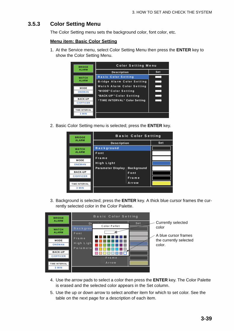
3.5.3 Color Setting MenuThe Color Setting menu sets the background color, font color, etc.
Menu item: Basic Color Setting
1. At the Service menu, select Color Setting Menu then press the ENTER key to show the Color Setting Menu.
2. Basic Color Setting menu is selected; press the ENTER key.
3. Background is selected; press the ENTER key. A thick blue cursor frames the cur-rently selected color in the Color Palette.
4. Use the arrow pads to select a color then press the ENTER key. The Color Palette is erased and the selected color appears in the Set column.
5. Use the up or down arrow to select another item for which to set color. See the table on the next page for a description of each item.
WATCHALARM
MODEONEMAN
BACK-UPC/OFFICER
TIME INTERVAL
3 MIN
BRIDGEALARM
Description Set
C olor S e tting Menu
Wa tc h A la rm C olor S e tting
B ridge A la rm C olor S e tting B a s ic C olor S e tting
“MODE” C olor S e tting
“BACK-UP ” C olor S e tting
“TIME INTERVAL Color Setting”
WATCHALARM
MODEONEMAN
BACK-UPC/OFFICER
TIME INTERVAL
3 MIN
BRIDGEALARM
Description Set
B a s ic C olor S e tting
B a c k ground F ont F ra me H igh L ight
- F ont- F ra me
- A rrow
Parameter Display - Background
WATCHALARM
MODEONEMAN
BACK-UPC/OFFICER
TIME INTERVAL
3 MIN
BRIDGEALARM
Description Set
B a s ic C olor S e tting
B a c k ground F ont F ra me H igh L ight P a ra me te r Dis pla y - B a c k g r o u n d
- F o n t
- F ra me - A rrow
Description Set
B a s ic C olor S e tting
B a c k groundF ontF ra meH igh L ightP a ra me te r Dis pla y-ll Baa yy c k g r o u n d
- F o n t
- F ra me- A rrow
C o lo r P a l le tCurrently selectedcolor
A blue cursor framesthe currently selectedcolor.

3. HOW TO SET AND CHECK THE SYSTEM
3-40
6. After you have set all items, press the ESC key. The save confirmation window appears.
7. Select Yes then press the ENTER key.
* See page 3-18 for location.
Bridge Alarm Color Setting
Set colors for the bridge alarm related displays, such as the Auto Alarm Pop-up Dis-play that appears when a bridge alarm is generated.
* See page 3-18 for location.
Watch Alarm Color Setting
Select the font color for the “WATCH ALARM” indication.
* See page 3-19 for location.
Menu item No. ofcolors Function Location*
Background 40 colors Background color (1)
Font 40 colors Normal font color (2)
Frame 40 colors Normal frame color (3)
High Light 40 colors Color of the highlight cursor (4)
Parameter Display Background
40 colors Background color for the Parameter Setting Display
(5)
Parameter Display Font
40 colors Font color for the Parameter Setting Display
(6)
Parameter Display Frame
40 colors Color of the frame in the ParameterSetting Display
(7)
Parameter Display Arrow
40 colors Color of the arrow in the ParameterSetting Display
(8)
Menu item No. of colors Function Location*
Bridge AlarmDisplay Page
40 colors Color for page number in the Bridge Alarm Display Page
(1)
“BRIDGE ALARM” Font
40 colors Color for “BRIDGE ALARM” (2)
Menu item No. of colors Function Location*
“WATCH ALARM” Font
40 colors Color for “WATCH ALARM” (1)

3. HOW TO SET AND CHECK THE SYSTEM
3-41
“MODE” Color Setting
Select the colors related to the “MODE” indication.
* See page “3-19 for location.
“BACK-UP” Color Setting
Select the colors related to the “BACK-UP” indication.
* See page 3-20 for location.
“TIME INTERVAL” Color Setting
Select the colors related to the “TIME INTERVAL” indication.
* See page 3-20 for location.
Menu item No. of colors Function Location*
“MODE” Font 40 colors Color for “MODE” (1)
Parameter Font 40 colors Color for the parameter (2)
“MODE”Background
40 colors Background color for “MODE” (3)
“ATTEND”,“ONEMAN”Background
40 colors Background color for “ATTEND”,“ONEMAN”
(4)
Menu item No. of colors Function Location*
“BACK-UP” Font 40 colors Color for “BACK-UP” (1)
Parameter Font 40 colors Color for the parameter (2)
Background 40 colors Background color for “BACK-UP” (3)
Menu item No. of colors Function Location*
“TIME INTER-VAL” Font
40 colors Color for “TIME INTERVAL” (1)
Parameter Font 40 colors Color for the parameter (2)
Background 40 colors Background color for “TIME INTERVAL” (3)

3. HOW TO SET AND CHECK THE SYSTEM
3-42
3.6 How to Edit the Alarm List If modification of the data uploaded from the PC is required, follow the procedure in this section to modify the settings from the Bridge Panel.
When the Alarm List editing screen is active, the system operates as follows:
• The system monitors the bridge alarm and watch alarm when the Alarm List editing screen is in use, but does not generate alarms.
• When you quit the Alarm List editing screen, the system generates bridge alarm if there is an alarm active.
• If an alarm is generated when the Alarm List editing screen is active, the BRIDGE ALARM box on the Bridge Panel flashes red, but the audible alarm does not sound from the Bridge Panel or Timer Reset Panel and no alarms are forwarded. The timer is reset when you quit the Alarm List editing screen. The 1st stage of the bridge alarm operates.
• You cannot use the Alarm List editing screen if a bridge alarm is active or the watch alarm is past the 2nd stage,
• If an alarm is generated, press the BUZ STOP and ACK keys to stop the alarms. Then you can use the Alarm List editing screen.
• After you acknowledge a bridge alarm with the ACK key, the Bridge Panel shows “Pending” until the cause for the alarm is removed. You can use the Alarm List edit-ing screen in this condition. When you quit the Alarm List editing screen, the bridge alarm and watch alarm timers are reset. If the cause of the bridge alarm has not been removed, the bridge alarm starts from the 1st stage.
Alarm List editing screen
The system restores the standby display when there is no menu operation in 60 sec-onds. Settings are not saved when this occurs.
1. At the standby display, press the LIST key to show the Bridge Alarm Display.2. Press the EDIT key, and the message "Enter Password" appears.
WATCHALARM
MODEONEMAN
BACK-UPC/OFFICER
BRIDGEALARM
No.1 Radar Sys Fail
No.2 Radar Sys Fail
No.3 Radar Sys Fail
No.1 Radar CPA/TCPA/GZ
No.2 Radar CPA/TCPA/GZ
No.3 Radar CPA/TCPA/GZ
No.1 RADAR System Error
No.2 RADAR System Error
Description
Secondary
Priority
001
002
003
004
005
006
007
008
Tag
Secondary
Secondary
Urgency
Urgency
Urgency
Secondary
Secondary
1 2 3 4 5 6 7 8 9 10 11 12
TIME INTERVAL
3 MIN
No.1 Radar Sys Fail
No.2 Radar Sys Fail
No.3 Radar Sys Fail
No.1 Radar CPA/AA TCPA/GZ
No.2 Radar CPA/AA TCPA/GZ
No.3 Radar CPA/AA TCPA/GZ
No.1 RADAR System Error
No.2 RADAR System Error
Description
Secondaryrr
Priority
001
002
003
004
005
006
007
008
Tag
Secondaryrr
Secondaryrr
Urgency
Urgency
Urgency
Secondaryrr
Secondaryrr
1 2 3 4 5 6 7 8 9 10 11 12
Enter Password

3. HOW TO SET AND CHECK THE SYSTEM
3-43
3. Press the up, down, left and right arrows on the Cursor pad followed by the LIST and ESC keys. This is the password to open the Alarm List editing screen.Page numbers appear at the top of the screen and the currently selected page number flashes. The cursor selects the first item in the selected page.
4. Use the left or right arrow to select the page to edit.5. Use the up or down arrow to select the item to edit then press the ENTER key.
For example, if you select Tag 004 on page 1, the screen looks like the one shown below. This tag is for the input signal connected to #7/8 of TB2 in the Processor Unit. Tag 001 on page 1 is for the input signal connected to #1/2 of TB2 in the Pro-cessor Unit.
As shown in the illustration there are 11 items per input signal.6. Use the arrow pads to select the item to edit then press the ENTER key.
For example, select Active/Inactive. The following window appears.
7. Use the left or right arrow to select setting then press the ENTER key.
1Selected page no.flashes every 0.5 s.
WATCHALARM
MODEONEMAN
BACK-UPC/OFFICER
TIME INTERVAL
3 MIN
BRIDGEALARM
No.1 Radar Sys Fail
No.2 Radar Sys Fail
No.3 Radar Sys Fail
No.1 Radar CPA/TCPA/GZ
No.2 Radar CPA/TCPA/GZ
No.3 Radar CPA/TCPA/GZ
No.1 RADAR System Error
No.2 RADAR System Error
Description
Secondary
Priority
001
002
003
004
005
006
007
008
Tag
Secondary
Secondary
Urgency
Urgency
Urgency
Secondary
Secondary
1 2 3 4 5 6 7 8 9 10 11 12
WATCHALARM
MODEONEMAN
BACK-UPC/OFFICER
TIME INTERVAL
3 MIN
BRIDGEALARM
Input Unit
Alarm Priority / Status
Channel Number/Modbus Address
Group Number
Alarm Text
Type of Signal
Urgency
PU1
Active
No.1 Radar CPA/TCPA/GZ004
Description Set
Active / Inactive
AL Close
01
04
ON Alarm Extend
WATCHALARM
MODEONEMAN
BACK-UPC/OFFICER
TIME INTERVAL
3 MIN
BRIDGEALARM
Alarm Type Repeat Alarm Address
Normal
No.1 Radar CPA/TCPA/GZ004
Description Set
Send to VDR Disable
WATCHALARM
MODEONEMAN
BACK-UPC/OFFICER
TIME INTERVAL
3 MIN
BRIDGEALARM
Input Unit
Alarm Priority / Status
Channel Number/Modbus Address
Group Number
Alarm Text
Type of Signal
Urgency
PU1
Active
No.1 Radar CPA/TCPA/GZ004
Description Set
Active / Inactive
AL Close
01
04
ON Alarm Extend
Input Unit
Alarm Priority / Status
Channel Number/rr Modbus Address
Group Number
Alarm Text
Type of Signal
Urgency
PU1
Active
No.1 Radar CPA/AA TCPA/GZ004
Description Set
Active / Inactive
AL Close
01
04
ONAlarm Extend
A c tive / Ina c tive
A c tive
Current setting

3. HOW TO SET AND CHECK THE SYSTEM
3-44
8. After you have set all items required, press the ESC key.9. To change another input signal, do steps 4 through 8.10.Press the ESC key to quit.
Description of Items in Alarm List editing screen
(1) Input UnitSet the medium which receives the alarm signals.PU1: No.1 Processor UnitPU2: No.2 Processor UnitModbus: ModbusPU2 is not shown when “No.2 Processor Unit Connection” is set for “Disabled”.
(2) Channel Number/Modbus AddressSelect digital channel or Modbus address. Use digital channel if Input Unit (above) is set for PU1 or PU2. In that case the setting range is 001-048. For Mod-bus, the setting range is 001-032.
See the previous section for how to enter alphanumeric data.
(3) Alarm TextEdit the name of the alarm for connected equipment. The name can have up to 32 alphanumeric characters. You can use upper case, lower case, numerals and symbols. If there are many alarm signals connected, be sure to select a name which identifies the alarm clearly. Characters are entered the same as described in the previous section. Alarm names are shown on the Bridge Alarm Display and Auto Alarm Pop-up Display.
(4) Group NumberThis system allows you to register in groups the equipment that transmits the REMOTE ACK OUT signal (buzzer stop) and receives the LOCAL ACK IN signal (buzzer stop).- PU1, PU2: 001-025- Modbus: 012-059For example, four types of alarm signals from the No.1 radar are connected to the system. Assign a group number to those alarm signals.
C hannel Number/Modbus Address
0 0 4
A la rm T e x t
Group Number
0 0

3. HOW TO SET AND CHECK THE SYSTEM
3-45
(5) Alarm Priority/StatusSet priority and status for the alarm selected. Consult with ship personnel to decide alarm priority. Priority is shown on the Bridge Alarm Display and Auto Alarm Pop-up Display.
(6) Type of SignalSet the type of contact signal input from external equipment, among the three choices described below.- AL Open: Contact signal opens when an alarm is generated (NC signal).- AL Close: Contact signal closes when an alarm is generated (NO signal).- Modbus: Modbus setting
(7) Active / InactiveMake an alarm active or inactive.Active: Selected alarm is watched by the system. Alarm name in the Alarm List is white.Inactive: Selected alarm is not watched by the system. Alarm name in the Alarm List is gray.
Alarm Priority / Status
P rima ry
Alarm Priority / Status
U rge nc y
Alarm Priority / Status
S e c onda ry
Alarm Priority / Status
E me rge nc y
A c tive / Ina c tive A c tive / Ina c tive
Ina c tive A c tive
WATCHALARM
MODEONEMAN
BACK-UPC/OFFICER
TIME INTERVAL
3 MIN
BRIDGEALARM
No.1 Radar Sys Fail
No.2 Radar Sys Fail
No.3 Radar Sys Fail
No.1 Radar CPA/TCPA/GZ
No.2 Radar CPA/TCPA/GZ
No.3 Radar CPA/TCPA/GZ
No.1 RADAR System Error
No.2 RADAR System Error
Description
Secondary
Priority
001
002
003
004
005
006
007
008
Tag
Secondary
Secondary
Urgency
Urgency
Urgency
Secondary
Secondary
1 2 3 4 5 6 7 8 9 10 11 12
Inactive: Alarm name in gray
Active: Alarm name in white
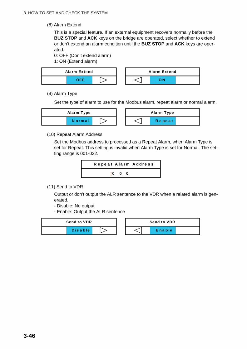
3. HOW TO SET AND CHECK THE SYSTEM
3-46
(8) Alarm ExtendThis is a special feature. If an external equipment recovers normally before the BUZ STOP and ACK keys on the bridge are operated, select whether to extend or don’t extend an alarm condition until the BUZ STOP and ACK keys are oper-ated.0: OFF (Don’t extend alarm)1: ON (Extend alarm)
(9) Alarm Type
Set the type of alarm to use for the Modbus alarm, repeat alarm or normal alarm.
(10) Repeat Alarm AddressSet the Modbus address to processed as a Repeat Alarm, when Alarm Type is set for Repeat. This setting is invalid when Alarm Type is set for Normal. The set-ting range is 001-032.
(11) Send to VDROutput or don’t output the ALR sentence to the VDR when a related alarm is gen-erated.- Disable: No output- Enable: Output the ALR sentence
Alarm Extend
OFF
Alarm Extend
ON
Alarm Type
N orma l
Alarm Type
R e pe a t
R e pe a t A la rm A ddre s s
0 0 0
Send to VDR
Dis a ble
Send to VDR
E na ble

AP-1
APPENDIX 1 JIS CABLE GUIDE
DTMTT
P Y
C Y S-S
3. Sheath Type
4. Armor Type 5. Shielding Type 6. Core Sheath
Ethylene Propylene
2. Insulation Type 1. Core Type Double core power line
Triple core power line
1mm Multi core
0.75mm twisted pair communications (1Q = quad cable)
Corrosive resistantSteel
Vinyl
All cores in one sheath
Individually sheathed cores
DPYCYS - 1.5 EX:
The following reference table lists gives the measurements of JIS cables commonly used with Furuno products:
DPYC
TTYCS-4
MPYC-5
Type Area Diameter
Core Cable
Diameter
DPYC-1.5 1.5mm2 1.56mm 11.7mm
DPYC-2.5 2.5mm2 2.01mm
1 2 3 4 5 6
MPYC - 51 2 3 4
Designation type Core Area (mm ) Designation type # of cores
DPYCY-2.5
DPYCYS-1.5
DPYCYS-2.5
MPYC-7
MPYCY-12
MPYCY-19
TTYCS-1
TTYCS-1Q
TTYCS-4
TTYCYS-1
JIS cable names may have up to 6 alphabetical characters, followed by a dash and a numerical value (example: DPYC-2.5). For core types D and T, the numerical designation indicates the cross-sectional Area (mm2) of the core wire(s) in the cable. For core types M and TT, the numerical designation indicates the number of core wires in the cable.
TPYC
12.8mm
2.5mm2 2.01mm 14.8mm
1.5mm2 1.56mm 14.6mm
2.5mm2 2.01mm 15.5mm
1mm2 1.29mm 13.2mm
1mm2 1.29mm 19.0mm
22.0mm1mm2 1.29mm
0.75mm2 1.11mm 10.1mm
11.3mm
16.3mm
21.1mm
2
0.75mm 1.11mm2
0.75mm 1.11mm2
0.75mm 1.11mm2
Type Area Diameter
Core Cable
Diameter
MPYC-4
MPYC-2
TPYCY-1.5
TPYCY-2.5
TPYCY-4
TPYCYS-1.5
1mm2
1mm2
1.5mm2 1.56mm 14.5mm
2.5mm2 2.01mm 15.5mm
4mm2 2.55mm 16.9mm
1.5mm2 1.56mm 15.2mm
Cables listed in the manual are usually shown as Japanese Industrial Standard (JIS). Use the following guide to locate an
1.29mm
1.29mm 10.0mm
11.2mm
equivalent cable locally.

A-2
A-1
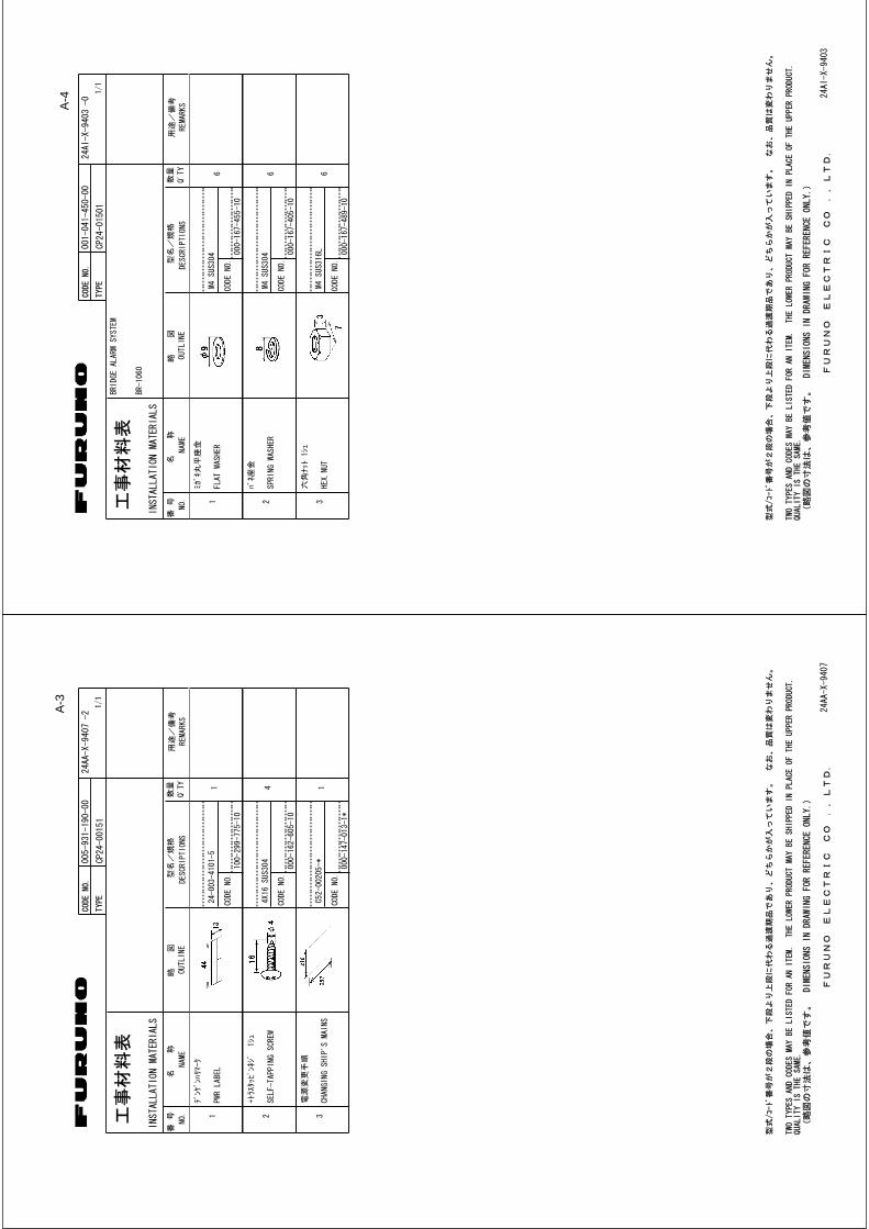
A-4
A-3

A-5

3/Jun/08 R.Esumi

4/Sep/09 R.Esumi

Mar.12'08 R.Esumi

Mar.12'08 R.Esumi
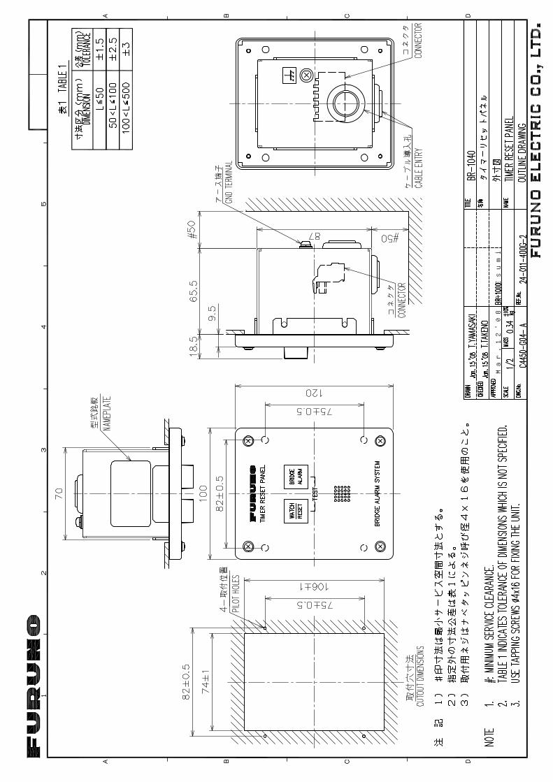
Mar.12'08 R.Esumi

Mar.12'08 R.Esumi

5/Feb/09 R.Esumi

1 2 4 5 63
B
A
D
C
*1)造船所手配。
注記
*2)オプション。
*3)キャビンパネルは最大4台まで分岐可能。
*1: SHIPYARD SUPPLY.
NOTE
*2: OPTION.
*3: MAX. 4 CABIN PANELS CAN BE INSTALLED AT ANOTHER ROOM.
*4)信号種類に応じてジャンパー設定を変更する。 *4: CHANGE JUMPER SETTING AS SIGNAL LEVEL.
1 2 3 4 5 6
J1
NC
7
TX-P
TX-N
RX-P
8
RX-N
NC
NC
NC
IV-2sq.*1
321TB2
4
GND
GND
GND
GND
5 6 7 8 321 4
GND
GND
GND
GND
5 6 7 8
TB3
321 4
GND
GND
GND
GND
5 6 7 8
TB4
321 4
GND
GND
GND
GND
5 6 7 8
TB5
321 4
GND
GND
GND
GND
5 6 7 8
TB6
321 4
GND
GND
GND
GND
5 6 7 8
TB7
321 4
GND
GND
GND
GND
5 6 7 8
TB8
321 4
GND
GND
GND
GND
5 6 7 8
TB9
321 4
GND
GND
GND
GND
5 6 7 8 321 4
GND
GND
GND
GND
5 6 7 8 321 4
GND
GND
GND
GND
5 6 7 8 321 4
GND
GND
5GND
GND
6 7 8
TB10
TB11
TB12
TB13
1 2 3 4 5 6 7 8 9 10
11
12
13
14
15
16
17
18
19
20
21
22
23
24
25
26
27
28
29
30
31
32
33
34
35
36
37
38
39
40
41
42
43
44
45
46
47
48
ALARM IN 1-4 ALARM IN 5-8 ALARM IN 9-12 ALARM IN 13-16 ALARM IN 17-20 ALARM IN 21-24 ALARM IN 25-28 ALARM IN 29-32 ALARM IN 33-36 ALARM IN 37-40 ALARM IN 41-44 ALARM IN 45-48
RJ45
21(-)
(+)
TB1
MPYC
*1
PROCESSOR UNIT制御部
BR-1020
P P
321 4 5 6 7 8 9 10
TB42
TB43
JP1
JP2
JP3
JP4
JP5
RXA
RXB
ISOG
TXA
TXB
321 4 5 6 7 8 9 10
JP1
JP2
JP3
JP4
JP5
RXA
RXB
ISOG
TXA
TXB
*4 *4
MODBUS IN/OUT 1 MODBUS IN/OUT 2
TD-A
TD-B
GND-ISO
RD-A
RD-B
GND-ISOIAS
TTYCS-4
*1
321 4
GND
5 6 7
TB18
321TB22
321 4GND
GND
GND
5 6 7 8
GND
321 4 5 6321TB26
321 4 5 6 7
TB20
321 4 5 6 7
TB19
321 4 5 6 7
TB21
同上
DITTO
MPYC*1
MPYC-7*1
MPYC-7*1
MPYC-7*1
MPYC-7*1
航法装置NAV EQUIPMENT
GND
GND
GND
12V
WABA
BUZ
STP
RST
GND
12V
WABA
BUZ
STP
RST
GND
12V
WABA
BUZ
STP
RST
TIMER RESET PANEL1 TIMER RESET PANEL2 TIMER RESET PANEL3 TIMER RESET PANEL4
GND
12V
WABA
BUZ
STP
RST
A+
COMB+
A+
COMB+ 1 2 3 4 5 6 7
SYSTEM FAIL OUT 1/2OPERATORSFITNESS IN 1-4
OPERATORS
TB27
TB28
321 4 5 6 7 8 9 10
JP1
JP2
JP3
JP4
JP5
RXA
RXB
ISOG
TXA
TXB
TB42/43
*4
TD-A
TD-B
GND-ISO
RD-A
RD-B
GND-ISOIAS
TTYCS-1*1
またはOR
同上
DITTO
同上
DITTO
同上
DITTO
VDROR
IAS
VDROR
IAS
321 4
TB30
NC
NC
321 4GND
GND
5 6 7 8
GND
TB31
AP1
AP2
NCNC
AUTOPILOT
オー
トパイ
ロッ
ト
PR-240
TB2(1,2)
PF
EXTERNALSIREN OUT
AUTOPILOTMODE IN/PF IN
FITNESS IN 5-7
同上
DITTO
NAME
名称
TITLE
kgMASS
DWG No.
SCALE
APPROVED
CHECKED
DRAWN
REF.No.INTERCONNECTION DIAGRAM
相互結線図
T.YAMASAKI BR-1000
ブリッジアラームシステム
BRIDGE ALARM SYSTEM
T.TAKENO
ACOM
MPYC-2*1
MPYC-2
MPYC-2
*1
*1
航法装置NAV EQUIPMENT
同上
同上
同上
同上
同上
同上
同上
同上
同上
同上
DITTO
同上
DITTO
12/Mar/09
13/Mar/09
C4450-C01- B 24-011-5035-1
1 2 3 4 5 6 7 8
NC
TX-P
TX-N
RX-P
RX-N
NC
NC
NC
RJ45
DPYC-1.5
*1
NETWORK
BR-1010BRIDGE PANELブリッジパネル
1 2 3
MJ-A3SPF
2
TB1
(-)
3(+)
1E
ミドリGRN
クロ
BLK
シロ
WHT
3A
(+)
(-)
GND
MJ-A3SPF0013,3.5m
CN1
1 2 3 4 5 6NC
MJ-A6SPF
NMEA1
1 2 3 4 5 6 7SHIELD
GND
+12V
RD2-C
RD2-H
TD2-B
TD2-A
NMEA2
IV-2sq.*1
クロ
BLK
シロ
WHT
*2
RX-H
RX-C
TD-A
TD-B
キ ミドリGRN
YEL
VDR
GPS
MJ-A6SPF0003,5/10m,φ
6
MJ-A7SPF0010,10m,φ
7*2
MJ-A7SPF0007,5m,φ
7
PR-240
AC/DCPOWER SUPPLY UNIT
TB1
7 6 5 4
ACIN
ACIN
DCIN+
DCIN-
TB2
ACFAIL
ACFAIL
1 2
24VDC
100/220VAC
1φ,50/60Hz
TB31(5,6)
BR-1020
MPYC-2
DPYC-1.5
DPYC-1.5
*1
*1
*1
IV-2sq.*1
TD1-A
TD1-B
RD1-H
RD1-C
SHIELD
MJ-A7SPF
FR-FTPC-CY
P5E-4PTX-BL-CB,2/5/10m
*2
PP
PP
P P
DITTO
DITTO
DITTO
DITTO
DITTO
DITTO
DITTO
DITTO
DITTO
321 4 5
TB36
321 4 5
TB33
321 4 5
TB34
321 4 5
TB35
GND
12V
DTY
ALM
BUZ
GND
12V
DTY
ALM
BUZ
GND
12V
DTY
ALM
BUZ
GND
12V
DTY
ALM
BUZ
CABIN PANEL5CABIN PANEL4CABIN PANEL3CABIN PANEL2
321 4
GND
5
TB32
12V
DTY
ALM
BUZ
CABIN PANEL1
7321 4 5 6
TB29
CABINTEST5
GND
GND
GND
GND
CABINTEST4
CABINTEST3
CABINTEST2
87GND
8
TB28
CABINTEST1
321 4 5 6 7
GND
12V
NC
DUTY
ALM
BUZ
キャビンパネルCABIN PANEL
IV-2sq.*1
TEST
BR-1030 #5
BR-1020
321 4
GND
GND
GND
GND
5 6 7 8321 4
GND
GND
GND
GND
5 6 7 8 321 4
GND
GND
GND
GND
5 6 7 8
1 2 3 4 5 6 7 8 9
10
11
12
TB23
TB24
TB25
321 4 5 6321 4 5 6
TB14
TB15
321 4 5 6 321 4 5 6
TB16
TB17
1+
1-
2+
2-
3+
3-
4+
4-
5+
5-
6+
6-
7+
7-
8+
8-
9+
9-
10+
10-
11+
11-
12+
12-
LOCAL ACK IN 1-4 LOCAL ACK IN 5-8 LOCAL ACK IN 9-12REMOTE ACKOUT 1-3
REMOTE ACK REMOTE ACK REMOTE ACKOUT 4-6 OUT 7-9 OUT 10-12
321 4 5 6 7
GND
12V
NC
DUTY
ALM
*1
BUZ
キャビンパネルCABIN PANEL
IV-2sq.*1
321 4 5 6 7
GND
12V
NC
DUTY
ALM
BUZ
キャビンパネルCABIN PANEL
IV-2sq.*1
TEST
TEST
BR-1030 #1
MPYC-7
321 4 5
TB41
321 4 5
TB40
321 4 5
TB39
321 4 5
TB38
GND
12V
DTY
ALM
BUZ
GND
12V
DTY
ALM
BUZ
GND
12V
DTY
ALM
BUZ
GND
12V
DTY
ALM
BUZ
CABIN PANEL7 CABIN PANEL8 CABIN PANEL9 CABIN PANEL10
321 4 5
TB37
GND
12V
DTY
ALM
BUZ
CABIN PANEL6
*1
MPYC-7
同上
同上
同上
DITTO
DITTO
DITTO
BR-1030#2
BR-1030#3
BR-1030#4
JB
*1
JB
*1
CABINTEST5
TB29(7)
*1
MPYC-7
*1
JB
同上
DITTO
BR-1030#6
6(TEST)
BR-1030#2
6(TEST)
6(TEST)
6(TEST)
BR-1030#3
BR-1030#4
BR-1030#5-#10
*1
MPYC-7
*3BR-1030 #11
SELECTIVE STANDARD:選択標準:4-14台
BETWEEN 4 AND 14 SETS
*1JB
同上
同上
同上
同上*2
*2
DITTO
DITTO
DITTO
DITTO
BR-1030#7
BR-1030#8
BR-1030#9
BR-1030#10
*1JB *1JB *1JB
同上
DITTO
同上
DITTO
同上
DITTO
同上
DITTO
同上
DITTO 航法装置
NAV EQUIPMENT航法装置NAV EQUIPMENT
MPYC
MPYC
*1
*1
321 4 5 6 7
GND
12V
WATCH_ALM
BRIDGE_ALM
BUZZER
BUZZER_STOP
TIMER_RESET
IV-2sq.*1
TIMER RESET PANELタイマーリセットパネル
BR-1040/1060
MPYC-2
MPYC-4*1
*1
EXT.SIREN
外部
サイレ
ン
電源
POWER
SUPPLY
25/Mar/09 R.Esumi

D
A
B
C
2 31
kgSCALE
APPROVED
CHECKED
DRAWN
MASS NAME
TITLE
名称
DWG.No. REF.No.
T.YAMASAKI
相互結線図
INTERCONNECTION DIAGRAMC4450-C02- A 24-011-5039-0
BR-1000
ブリッジアラームシステム(No.2)
BRIDGE ALARM SYSTEM (No.2)
T.TAKENO
*1)造船所手配。
注記
*2)オプション。
*1: SHIPYARD SUPPLY.
NOTE
*2: OPTION.
1 2 3 4 5 6 7
RJ45
8
1 2 3 4 5 6 7
RJ45
8
1 2 3 4 5 6 7
RJ45
81 2
イーサネットハブETHERNET HUBHUB-101 *2
1 2 3 4 5 6
J1
NC
7
RJ45
TX-P
TX-N
RX-P
8
RX-N
NC
NCNC
DPYC-1.5*1
21(-)
(+)
TB1
1 2 3 4 5 6
J1
NC
7
RJ45
TX-P
TX-N
RX-P
8
RX-N
NC
NCNC
MOD-Z072,5m
1 2 3
MJ-A3SPF
ミドリGRN
クロ
BLK
シロ
WHT
3A
MJ-A3SPF0013,3.5m
(+)
(-)
GND
IV-2sq.*1
BRIDGE PANELBR-1010
ブリッジパネル
NC
TX-P
TX-N
RX-P
RX-N
NC
NC
NC
1 2 3 4 5 6 7
RJ45
8
VH2P-MVVS0.75x2C,3.5m
クロ
BLK
シロ
WHT
P5E-4PTX-BL-CB
5m
(CAT5)
STPLANCABLE
21(-)
(+)
TB1
DPYC-1.5*1
BR-1020(No.2) *2
TB31
PFGND
5 6
PR-240
TB2(1,2)
PROCESSOR UNIT制御部BR-1020(No.1)
PROCESSOR UNIT制御部
CN1
CN5
23/May/08
26/May/08
+ - + - + - + -
JUNCTION BOX *1
BR-1020(No.1)
TPYC-1.5 *1
2
TB1
(-)
3(+)
1E
IV-2sq.*1
DPYC-1.5
TB1
7 6 5 4
ACIN
ACIN
DCIN+
DCIN-
TB2
ACFAIL
ACFAIL
1 2
PR-240*2AC/DC POWER
SUPPLY UNIT
DPYC-1.5
*1
*1
MPYC-2*1
24VDC
100/220VAC
1φ,50/60Hz
10/Jun/08 R.Esumi

PROCESSOR UNIT CONNECTION LIST S-3
ALARM IN REMOTE ACK OUTTerminal No. Device Signal Name, Type Terminal No. Device
TB2 #1/2 TB14 #1/2#3/4 #3/4#5/6 #5/6#7/8 #7/8
TB15 #1/2TB3 #1/2 #3/4
#3/4 #5/6#5/6 #7/8#7/8 TB16 #1/2
#3/4TB4 #1/2 #5/6
#3/4 #7/8#5/6 TB17 #1/2#7/8 #3/4
#5/6TB5 #1/2 #7/8
#3/4#5/6 LOCAL ACK IN#7/8 Terminal No. Device
TB23 #1/2TB6 #1/2 #3/4
#3/4 #5/6#5/6 #7/8#7/8 TB24 #1/2
#3/4TB7 #1/2 #5/6
#3/4 #7/8#5/6 TB25 #1/2#7/8 #3/4
#5/6TB8 #1/2 #7/8
#3/4 TB17 #1/2#5/6 #3/4#7/8 #5/6
#7/8TB9 #1/2
#3/4 OPERATOR FITNESS IN#5/6 Terminal No. Device#7/8 TB27 #1/2
#3/4TB10 #1/2 #5/6
#3/4 #7/8#5/6 TB28 #1/2#7/8 #3/4
#5/6TB11 #1/2
#3/4 CABIN PANEL#5/6 Terminal No. Device#7/8 TB32
TB33TB12 #1/2 TB34
#3/4 TB35#5/6 TB36#7/8 TB37
TB38TB13 #1/2 TB39
#3/4 TB40#5/6 TB41#7/8
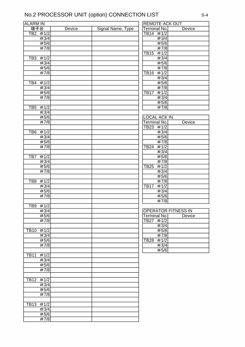
No.2 PROCESSOR UNIT (option) CONNECTION LIST S-4
ALARM IN REMOTE ACK OUT端子台 Device Signal Name, Type Terminal No. Device
TB2 #1/2 TB14 #1/2#3/4 #3/4#5/6 #5/6#7/8 #7/8
TB15 #1/2TB3 #1/2 #3/4
#3/4 #5/6#5/6 #7/8#7/8 TB16 #1/2
#3/4TB4 #1/2 #5/6
#3/4 #7/8#5/6 TB17 #1/2#7/8 #3/4
#5/6TB5 #1/2 #7/8
#3/4#5/6 LOCAL ACK IN#7/8 Terminal No. Device
TB23 #1/2TB6 #1/2 #3/4
#3/4 #5/6#5/6 #7/8#7/8 TB24 #1/2
#3/4TB7 #1/2 #5/6
#3/4 #7/8#5/6 TB25 #1/2#7/8 #3/4
#5/6TB8 #1/2 #7/8
#3/4 TB17 #1/2#5/6 #3/4#7/8 #5/6
#7/8TB9 #1/2
#3/4 OPERATOR FITNESS IN#5/6 Terminal No. Device#7/8 TB27 #1/2
#3/4TB10 #1/2 #5/6
#3/4 #7/8#5/6 TB28 #1/2#7/8 #3/4
#5/6TB11 #1/2
#3/4#5/6#7/8
TB12 #1/2#3/4#5/6#7/8
TB13 #1/2#3/4#5/6#7/8