installation manual central fire detection panel bz...
TRANSCRIPT
INSTALLATION MANUAL
BDL−4.998.098.932A1.en / 06.12.2000
ST−FIR/ PRM1 / deh
Seite 11
Central fire detection panelBZ 500 LSN

Installation manual BZ 500 LSN
BDL−4.998.098.932A1.en / 06.12.2000
ST−FIR/ PRM1/ dehpage 2
Summary1. Installation instructions 3. . . . . . . . . . . . . . . . . . . . . . . . . . . . . . . . . . . . . . . . 1.1. Notes on installation location 3. . . . . . . . . . . . . . . . . . . . . . . . . . . . . . . . . . . . . 1.2. Module layout 4. . . . . . . . . . . . . . . . . . . . . . . . . . . . . . . . . . . . . . . . . . . . . . . . . . 1.3. Installation process 5. . . . . . . . . . . . . . . . . . . . . . . . . . . . . . . . . . . . . . . . . . . . . 1.4. Expansion module installation process 9. . . . . . . . . . . . . . . . . . . . . . . . . . . .
2. Connections 13. . . . . . . . . . . . . . . . . . . . . . . . . . . . . . . . . . . . . . . . . . . . . . . . . 2.1. General overview of the ANNE 10 connections board 13. . . . . . . . . . . . . . 2.2. Interconnection of internal modules 16. . . . . . . . . . . . . . . . . . . . . . . . . . . . . . 2.3. LSN elements 17. . . . . . . . . . . . . . . . . . . . . . . . . . . . . . . . . . . . . . . . . . . . . . . . . 2.4. Interface for MOD 300, UGM 2020 and RUBIN peripherals 18. . . . . . . . . .
3. Coding 20. . . . . . . . . . . . . . . . . . . . . . . . . . . . . . . . . . . . . . . . . . . . . . . . . . . . . . . 3.1. ANNE 10 connections board. 20. . . . . . . . . . . . . . . . . . . . . . . . . . . . . . . . . . . . 3.2. ERSE 10 interface expansion 20. . . . . . . . . . . . . . . . . . . . . . . . . . . . . . . . . . . 3.3. ATE 100 LSN display panel 21. . . . . . . . . . . . . . . . . . . . . . . . . . . . . . . . . . . . . 3.4. TRN relay module panel 22. . . . . . . . . . . . . . . . . . . . . . . . . . . . . . . . . . . . . . . 3.5. Relay panel circuit board 23. . . . . . . . . . . . . . . . . . . . . . . . . . . . . . . . . . . . . . .
4. Configuration 25. . . . . . . . . . . . . . . . . . . . . . . . . . . . . . . . . . . . . . . . . . . . . . . .
5. Commisssioning 26. . . . . . . . . . . . . . . . . . . . . . . . . . . . . . . . . . . . . . . . . . . . .
6. Notes on maintenance and service 27. . . . . . . . . . . . . . . . . . . . . . . . . . . . 6.1. General 27. . . . . . . . . . . . . . . . . . . . . . . . . . . . . . . . . . . . . . . . . . . . . . . . . . . . . . 6.2. Documents 27. . . . . . . . . . . . . . . . . . . . . . . . . . . . . . . . . . . . . . . . . . . . . . . . . . . 6.3. Resetting the hardware 28. . . . . . . . . . . . . . . . . . . . . . . . . . . . . . . . . . . . . . . . 6.4. Testing battery charge voltage 29. . . . . . . . . . . . . . . . . . . . . . . . . . . . . . . . . . . 6.5. Starting deeply discharged batteries 29. . . . . . . . . . . . . . . . . . . . . . . . . . . . . 6.6. Setting battery charge voltage 30. . . . . . . . . . . . . . . . . . . . . . . . . . . . . . . . . . . 6.7. Replacement and disposal 30. . . . . . . . . . . . . . . . . . . . . . . . . . . . . . . . . . . . . . 6.8. Measuring system for fault finding 31. . . . . . . . . . . . . . . . . . . . . . . . . . . . . . .
7. Technical data 32. . . . . . . . . . . . . . . . . . . . . . . . . . . . . . . . . . . . . . . . . . . . . . . . 7.1. Dimensions/weight/colour of the control unit 32. . . . . . . . . . . . . . . . . . . . . . . 7.2. Ambient conditions 32. . . . . . . . . . . . . . . . . . . . . . . . . . . . . . . . . . . . . . . . . . . . . 7.3. Power supply 33. . . . . . . . . . . . . . . . . . . . . . . . . . . . . . . . . . . . . . . . . . . . . . . . . 7.4. Transmission equipment control 33. . . . . . . . . . . . . . . . . . . . . . . . . . . . . . . . . 7.5. ERWE 10 voltage transformer 33. . . . . . . . . . . . . . . . . . . . . . . . . . . . . . . . . . 7.6. Switching outputs (panel points) 34. . . . . . . . . . . . . . . . . . . . . . . . . . . . . . . . . 7.7. Serial interfaces 34. . . . . . . . . . . . . . . . . . . . . . . . . . . . . . . . . . . . . . . . . . . . . . . 7.8. LSN components 35. . . . . . . . . . . . . . . . . . . . . . . . . . . . . . . . . . . . . . . . . . . . . . 7.9. Fuses 35. . . . . . . . . . . . . . . . . . . . . . . . . . . . . . . . . . . . . . . . . . . . . . . . . . . . . . . .
8. List of abbreviations 36. . . . . . . . . . . . . . . . . . . . . . . . . . . . . . . . . . . . . . . . . .
9. Notices 37. . . . . . . . . . . . . . . . . . . . . . . . . . . . . . . . . . . . . . . . . . . . . . . . . . . . . .
Installation manual BZ 500 LSN
BDL−4.998.098.932A1.en / 06.12.2000
ST−FIR/ PRM1/ dehpage 3
1. Installation instructions
1.1. Notes on the installation location
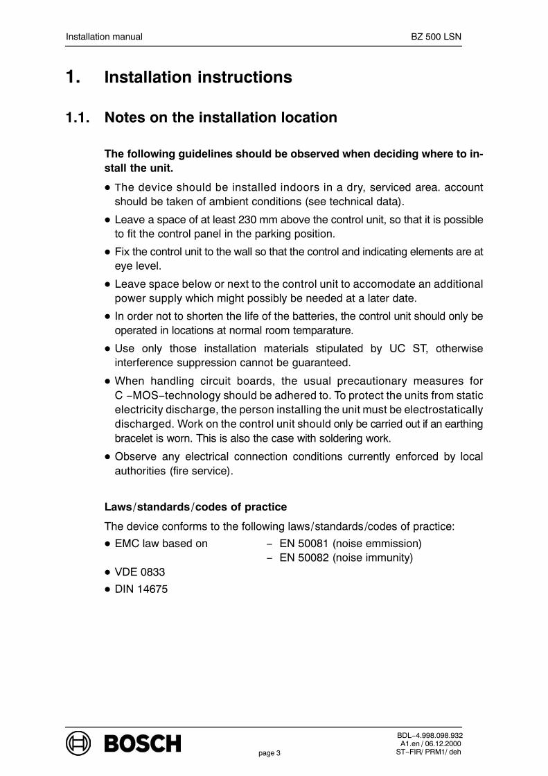
The following guidelines should be observed when deciding where to in-stall the unit.
The device should be installed indoors in a dry, serviced area. accountshould be taken of ambient conditions (see technical data).
Leave a space of at least 230 mm above the control unit, so that it is possibleto fit the control panel in the parking position.
Fix the control unit to the wall so that the control and indicating elements are ateye level.
Leave space below or next to the control unit to accomodate an additionalpower supply which might possibly be needed at a later date.
In order not to shorten the life of the batteries, the control unit should only beoperated in locations at normal room temparature.
Use only those installation materials stipulated by UC ST, otherwiseinterference suppression cannot be guaranteed.
When handling circuit boards, the usual precautionary measures forC −MOS−technology should be adhered to. To protect the units from staticelectricity discharge, the person installing the unit must be electrostaticallydischarged. Work on the control unit should only be carried out if an earthingbracelet is worn. This is also the case with soldering work.
Observe any electrical connection conditions currently enforced by localauthorities (fire service).
Laws/standards/codes of practice
The device conforms to the following laws/standards/codes of practice:
EMC law based on − EN 50081 (noise emmission)− EN 50082 (noise immunity)
VDE 0833
DIN 14675
Installation manual BZ 500 LSN
BDL−4.998.098.932A1.en / 06.12.2000
ST−FIR/ PRM1/ dehpage 4
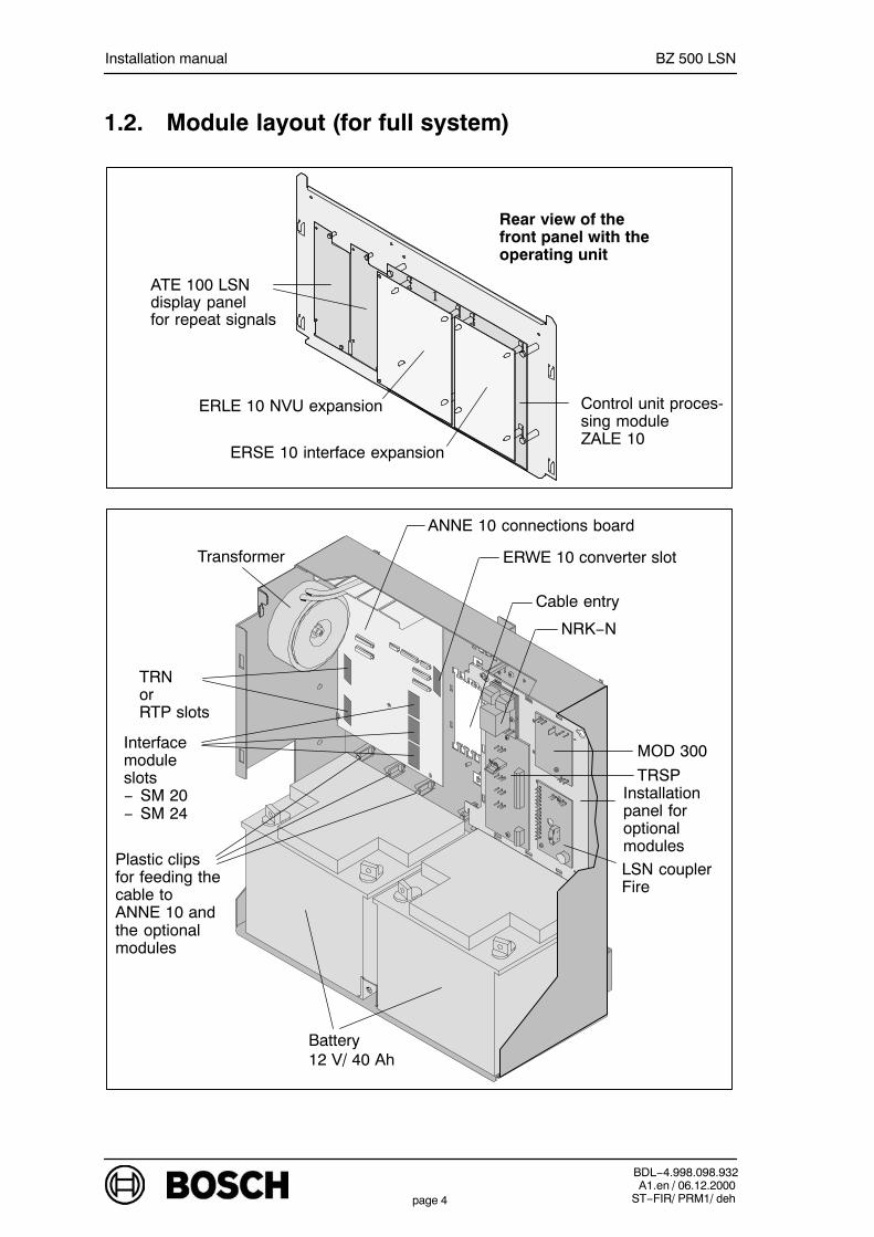
1.2. Module layout (for full system)
1
Rear view of thefront panel with theoperating unit
NRK−N
Installationpanel foroptionalmodules
Plastic clips for feeding thecable toANNE 10 andthe optionalmodules
TRN or RTP slots
ANNE 10 connections board
Transformer
Interfacemoduleslots− SM 20− SM 24
Cable entry
Battery12 V/ 40 Ah
LSN couplerFire
MOD 300
TRSP
ATE 100 LSNdisplay panelfor repeat signals
Control unit proces-sing moduleZALE 10
ERLE 10 NVU expansion
ERSE 10 interface expansion
ERWE 10 converter slot
Installation manual BZ 500 LSN
BDL−4.998.098.932A1.en / 06.12.2000
ST−FIR/ PRM1/ dehpage 5
1.3. Notes on the installation location
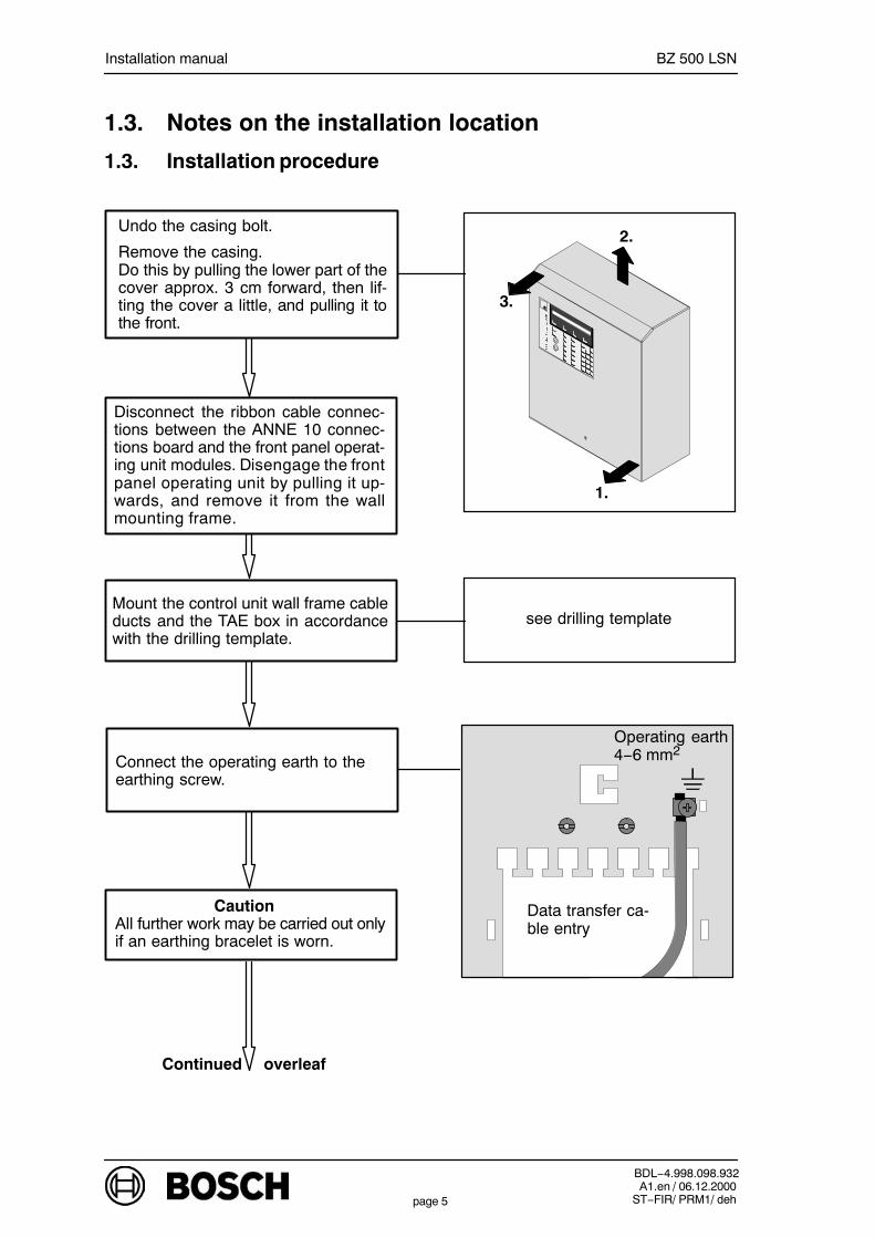
1.3. Installation procedure
Mount the control unit wall frame cableducts and the TAE box in accordancewith the drilling template.
Undo the casing bolt.
Remove the casing. Do this by pulling the lower part of thecover approx. 3 cm forward, then lif-ting the cover a little, and pulling it tothe front.
see drilling template
Continued overleaf
1.
3.
2.
Disconnect the ribbon cable connec-tions between the ANNE 10 connec-tions board and the front panel operat-ing unit modules. Disengage the frontpanel operating unit by pulling it up-wards, and remove it from the wallmounting frame.
Caution All further work may be carried out onlyif an earthing bracelet is worn.
Operating earth4−6 mm2
Data transfer ca-ble entry
Connect the operating earth to theearthing screw.

Installation manual BZ 500 LSN
BDL−4.998.098.932A1.en / 06.12.2000
ST−FIR/ PRM1/ dehpage 6
Additional earthwire terminal
Connect the mains cable to the 230Vterminal on the ANNE 10 connectionsboard. Press the unlocking lever backwith a screwdriver, and insert the wirefrom above.Pinch off the protective conductor asclose as possible (it does not come intocontact, protection class II).
Strip, and relieve the strain on the peri-pheral cable (above or below the cableentry). Connect the shielding wire asclose as possible to the terminal Stickthe self adhesive labels, which have si-gnal names printed on them, to the ap-propriate connector.
Continued overleaf
Data transfer cableentry
Cabletie
J−Y(St)Y
In order to minimise electromagneticirradiation:− use only telecomunications cable
with static shielding− connect the shielding wire as
closely as possible (max. 3 cm)
SI MAINS
230Vinput
ANNE 10
Unlocking lever
NL1
Slot the RTP, TRN, SM 20, SM 24 andERWE 10 modules into the ANNE 10connections board as required. Fit anyoptional modules to the installation pa-nel in the wall mounting frame.See chapters 1.4.1 and 1.4.2 for notes
Cable tie
Caution Before carrying out furtherwork, check that the 230V mains cableis off circuit. Mains voltage should pre-ferably be protected by an M 10A fuse,and as a separate circuit.Put the ferrite sleeve over the NYM3x1.5 mains cable (230 V). Using theNYM I 3x2.5, strip the mains cable ca-sing beforehand. Fix the ferrite sleeveto the wall mounting frame using a ca-ble tie.
NYMFerrite shell
Cable tie

Installation manual BZ 500 LSN
BDL−4.998.098.932A1.en / 06.12.2000
ST−FIR/ PRM1/ dehpage 7
Fit ERSE 10, ERLE 10, ATE 100 LSN and the key switch to theback of the front panel as required.Write the repeat signal stickers andstick them to the front panel as requi-red.
Insert the front panel operating unit inthe maintenance position.
Continued overleaf
Front panel in the maintenanceposition
Connect the ZALE 10, ERSE 10,ERLE 10 and ATE 100 LSN modules tothe ANNE 10 (ribbon cable).
See chapter 2.2 for notes
See chapters 1.4.3 and 1.4.4 fornotes
See chapter 2.2 for notes
Insert the batteries, connect to theANNE 10 and close the terminal cov-ers.Connect PTC as required.
PC port
LSN
SYSTEM ON
Move the”SYSTEM ON” link from theANNE 10 connections board.

Installation manual BZ 500 LSN
BDL−4.998.098.932A1.en / 06.12.2000
ST−FIR/ PRM1/ dehpage 8
Screw in the 230 V mains fuse. Themains supply fuse must be removedagain when work is carried out on thepower pack. Make the unit operational by pluggingin the ”SYSTEM ON” jumper. The ”SY-STEM ON” jumper turns the controlunit electronics on and off.
Put on the container cover. Do this bysliding the cover upwards, holding itaway slightly at the bottom and thenraising cover about 10 mm and lettingit drop down to engage. Push the co-ver down at the bottom.
Check all control unit, detector and pe-ripheral device functions. If all thefunctions are working correctly, placethe installation handbook and the in-ventory details in front of the batteries.
Screw on the casing. Seal the screwwith a paper seal.Fill in the line assignment list and storeit together with the operating instruc-tions in the optional document pocketor near the control unit.
3.
1.
2.
Paper seal
Important notes:
Before plugging the PC/laptop into thePC port, the interface module for inter-face 1 (COM1), which may already beoccupied, must be removed. Confi-gure the control unit by downloadingfrom the PC/laptop. After configurationand once the PC/laptop interface ca-ble has been removed, the interfacecan be occupied once more.See chapter 4 for notes
COM1
PC port
LSN
SYSTEM ON
PC port
Inte
rfac
e 1
Installation manual BZ 500 LSN
BDL−4.998.098.932A1.en / 06.12.2000
ST−FIR/ PRM1/ dehpage 9
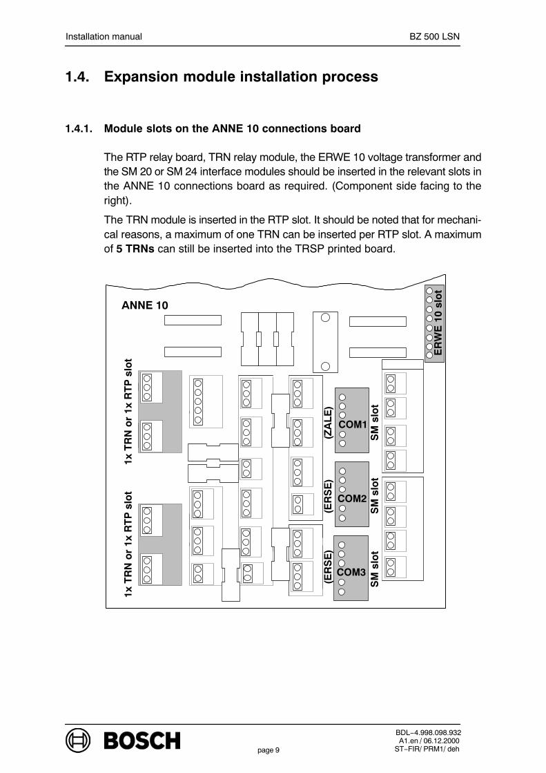
1.4. Expansion module installation process
1.4.1. Module slots on the ANNE 10 connections board
The RTP relay board, TRN relay module, the ERWE 10 voltage transformer andthe SM 20 or SM 24 interface modules should be inserted in the relevant slots inthe ANNE 10 connections board as required. (Component side facing to theright).
The TRN module is inserted in the RTP slot. It should be noted that for mechani-cal reasons, a maximum of one TRN can be inserted per RTP slot. A maximumof 5 TRNs can still be inserted into the TRSP printed board.
COM1
COM2
ANNE 10
COM3
ER
WE
10
slo
t
SM
slo
t
1x T
RN
or
1x R
TP
slo
t1x
TR
N o
r 1x
RT
P s
lot
SM
slo
tS
M s
lot
(ZA
LE
)(E
RS
E)
(ER
SE
)

Installation manual BZ 500 LSN
BDL−4.998.098.932A1.en / 06.12.2000
ST−FIR/ PRM1/ dehpage 10
1.4.2. Installation of optional modules
The installation plate is engaged atthe bottom in slots and is held by fa-stening screws at the top to secure itto the wall mounting frame. (installa-tion example, see fig.).The modules on the installation plateshould always be cabled on the leftso that the installation plate can laterbe engaged in the maintenance posi-tion.
LSA+distribu-tor
With the exception of AT 2000, whichmust be mounted on the installationplate if the TAE box is has been fittedin the designated place inside thecontrol unit, all other optional modu-les can be mounted either directlyonto the wall mounting frame or onthe installation plate, depending onthe space available (installation example, see fig.)
TRSP
NRK N
Installation plate fastening screws
MOD 300NRK N
LSNcoupler
Installation plate locating slots
Slots for engaging the installationplate in the maintenance position
Continued overleaf
AT 2000

Installation manual BZ 500 LSN
BDL−4.998.098.932A1.en / 06.12.2000
ST−FIR/ PRM1/ dehpage 11
Installation plate engaged in themaintenance position.
1.4.3. In installation of ATE 100 LSN display panel, ERLE 10 LSN expansion,ERSE 10 interface expansion
ATE 100 LSN:Screw the ATE in the position pro-vided on the front panel.ERLE 10:Push the spacer onto theZALE 10. Press ERLE 10 ontothe spacer.ERSE 10:Push the spacer onto theZALE 10. Press ERSE 10 ontothe spacer.
Ribbon cable connections, seechapter 2.2Coding for ATE 100 LSNsee chapter 3.3
The expansion modules aremounted on the back of the frontpanel.
ATE 100 LSN
ERSE 10 interface expansion
ERLE 10 NVU expansion
Rear view of front panel
ATE 100 LSN
ZALE 10
Installation manual BZ 500 LSN
BDL−4.998.098.932A1.en / 06.12.2000
ST−FIR/ PRM1/ dehpage 12
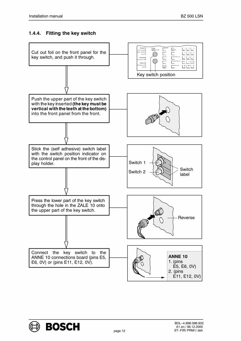
1.4.4. Fitting the key switch
Cut out foil on the front panel for thekey switch, and push it through.
Press the lower part of the key switchthrough the hole in the ZALE 10 ontothe upper part of the key switch.
Connect the key switch to theANNE 10 connections board (pins E5,E6, 0V) or (pins E11, E12, 0V).
ANNE 101. (pins
E5, E6, 0V)2. (pins
E11, E12, 0V)
Internal buzzer
Switch off
Reset
Control
Service
Further
function
Zone
detectors
Alarm
Transmission unit
Extinguishing area
Switching point
Operation
Code operation
Daytime operation
Service
Controlling
Transmission unit
Switch off
Transmission unit
Alarm
ABC
JKL
STU
DEF
MNO
VWX
GHI
PQR
YZ
1 2 3
4 5 6
7 8 9
CE 0 enter
yes stop no
−/:
Key switch position
Push the upper part of the key switchwith the key inserted (the key must bevertical with the teeth at the bottom)into the front panel from the front.
Stick the (self adhesive) switch labelwith the switch position indicator onthe control panel on the front of the dis-play holder.
Switchlabel
0
02
1
Switch 1
Switch 2
Reverse
Installation manual BZ 500 LSN
BDL−4.998.098.932A1.en / 06.12.2000
ST−FIR/ PRM1/ dehpage 13
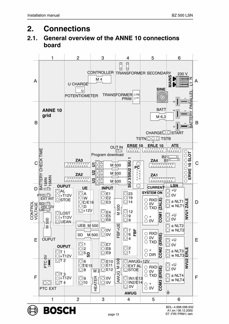
2. Connections2.1. General overview of the ANNE 10 connections
board
ER
WE
10
SL
OT
3 4 5 6
A
B
C
D
1
EXTPTC
T 4+T12VT 3
T 2+T12VT 1
109
87/E156
521
SD
HE
AT
ER
0V0V
M 2
UEB
PT
C0V
OUPUT
UEAN+T12VLOST
STOE+T12VAL
0V
E12E11E10
E9E8E7
0V0V
E6E5E4
E3E2E1
INPUTUE
IN2/E14IN1/E13
STOEEXT AL
AW
UG
AWUG+12V
FB
F
FB
F+
UE
12
467
8912
141923
+12VDC/E16WA
OUPUT
0V+
TXD0VRXD
0V+
TXD0VRXD
DIR+
TXD0VRXD
M 500
SIU
3S
IIU2
SIU
1
U3
U2
U1
+−
+−
+−
w NLT2a NLT2
0V+U
w NLT1a NLT1
0V+U
NV
U1
ZA
LE
ZA2
ZA3
1MIN
15M
IN
EXT INT
BA
TT
ER
Y C
HE
CK
TIM
E
ERSE 10
PC
INOUT
Program download
ERLE 10 ATE
ZA1
ZA4
SYSTEM ON
CURRENT LSN
B1B2
+−
+ −
+−
BA
TT
ER
YP
AR
ALL
EL
M 6,3
BATT
TSTN+
TSTB
CHARGE START
M 4
CONTROLLER
U CHARGE
POTENTIOMETER
TRANSFORMER SECONDARY
MA
INS
21
TRANSFORMER
24V 12VUE
SD
CO
NT
RO
LV
OLT
AG
E
2
3 4 5 61 2
E
F
A
B
C
D
E
F
ANNE 10grid
L1N
230 V
SINE
AWUG
PTC
PRIM
M 500
M 500
w NLT4a NLT4
0V+U
w NLT3a NLT3
0V+U
NV
U2
ER
LE
CO
M1
(ZA
LE
)C
OM
2 (E
RS
E)
CO
M3
(ER
SE
)
M 5
00
SD M 500
OUPUT
M 5
00M
500
M 500
Installation manual BZ 500 LSN
BDL−4.998.098.932A1.en / 06.12.2000
ST−FIR/ PRM1/ dehpage 14
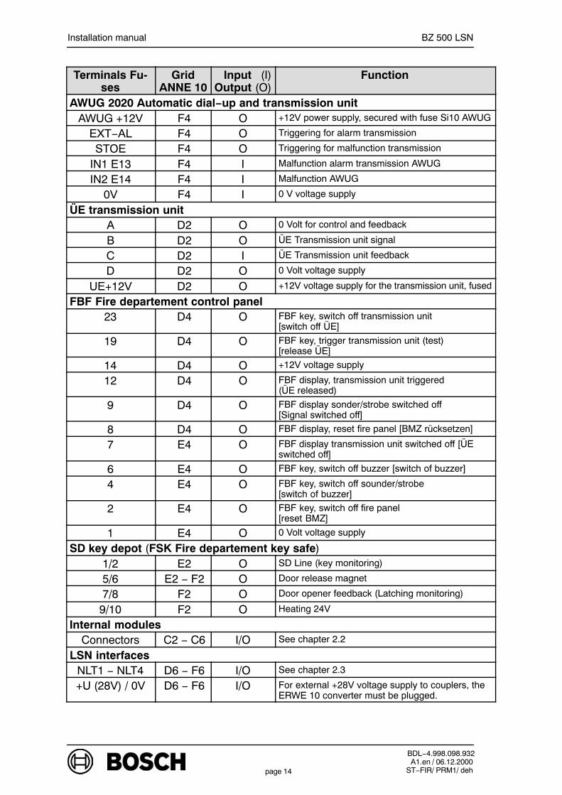
Terminals Fu-ses
GridANNE 10
Input (I)Output (O)
Function
AWUG 2020 Automatic dial−up and transmission unitAWUG +12V F4 O +12V power supply, secured with fuse Si10 AWUG
EXT−AL F4 O Triggering for alarm transmission
STOE F4 O Triggering for malfunction transmission
IN1 E13 F4 I Malfunction alarm transmission AWUG
IN2 E14 F4 I Malfunction AWUG
0V F4 I 0 V voltage supply
ÜE transmission unitA D2 O 0 Volt for control and feedback
B D2 O ÜE Transmission unit signal
C D2 I ÜE Transmission unit feedback
D D2 O 0 Volt voltage supply
UE+12V D2 O +12V voltage supply for the transmission unit, fused
FBF Fire departement control panel23 D4 O FBF key, switch off transmission unit
[switch off ÜE]
19 D4 O FBF key, trigger transmission unit (test)[release ÜE]
14 D4 O +12V voltage supply
12 D4 O FBF display, transmission unit triggered(ÜE released)
9 D4 O FBF display sonder/strobe switched off[Signal switched off]
8 D4 O FBF display, reset fire panel [BMZ rücksetzen]
7 E4 O FBF display transmission unit switched off [ÜEswitched off]
6 E4 O FBF key, switch off buzzer [switch of buzzer]
4 E4 O FBF key, switch off sounder/strobe [switch of buzzer]
2 E4 O FBF key, switch off fire panel[reset BMZ]
1 E4 O 0 Volt voltage supply
SD key depot (FSK Fire departement key safe)1/2 E2 O SD Line (key monitoring)
5/6 E2 − F2 O Door release magnet
7/8 F2 O Door opener feedback (Latching monitoring)
9/10 F2 O Heating 24V
Internal modulesConnectors C2 − C6 I/O See chapter 2.2
LSN interfacesNLT1 − NLT4 D6 − F6 I/O See chapter 2.3
+U (28V) / 0V D6 − F6 I/O For external +28V voltage supply to couplers, theERWE 10 converter must be plugged.
Installation manual BZ 500 LSN
BDL−4.998.098.932A1.en / 06.12.2000
ST−FIR/ PRM1/ dehpage 15
Terminals Fu-ses
GridANNE 10
Input (I)Output (O)
Function
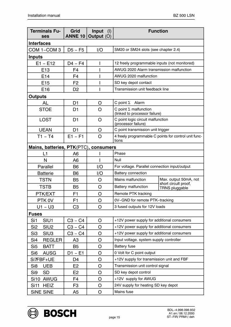
InterfacesCOM 1−COM 3 D5 − F5 I/O SM20 or SM24 slots (see chapter 2.4)
InputsE1 − E12 D4 − F4 I 12 freely programmable inputs (not monitored)
E13 F4 I AWUG 2020 Alarm transmission malfunction
E14 F4 I AWUG 2020 malfunction
E15 F2 I SD key depot contact
E16 D2 I Transmission unit feedback line
OutputsAL D1 O C point Alarm
STOE D1 O C point malfunction(linked to processor failure)
LOST D1 O C point logic circuit malfunction(processor failure)
UEAN D1 O C point transmission unit trigger
T1 − T4 E1 − F1 O 4 freely programmable C points for control unit func-tions
Mains, batteries, PTK(PTC), consumersL1 A6 I Phase
N A6 I Null
Parallel B6 I/O For voltage. Parallel connection input/output
Batterie B6 I/O Battery connection
TSTN B5 O Mains malfunction Max. output 50mA, notshort circuit proof
TSTB B5 O Battery malfunctionshort circuit proof,TRNS pluggable
PTK/EXT F1 O Remote PTK tracking
PTK 0V F1 O 0V−GND for remote PTK−tracking
U1 − U3 C3 O 3 fused outputs for 12V loads
FusesSi1 SIU1 C3 − C4 O +12V power supply for additional consumers
Si2 SIU2 C3 − C4 O +12V power supply for additional consumers
Si3 SIU3 C3 − C4 O +12V power supply for additional consumers
Si4 REGLER A3 O Input voltage. system supply controller
Si5 BATT B5 O Battery fuse
Si6 AUSG D1 − E1 O 0 Volt for C point output
Si7FBF+UE D4 O +12V supply for transmission unit and FBF
Si8 UEB E2 O Transmission unit control signal
Si9 SD E2 O SD key depot control
Si10 AWUG F4 O +12V supply for AWUG
Si11 HEIZ F3 O 24V supply for heating SD key depot
SiNE SiNE A5 O Mains fuse

Installation manual BZ 500 LSN
BDL−4.998.098.932A1.en / 06.12.2000
ST−FIR/ PRM1/ dehpage 16
2.2. Electrical connection of internal modules
ZA2
ZA3
ERSE ERLE ATE
ZA1
ZA4
+−
+−
+ −
ANNE 10
PTC 0V
PTC EXT
Batt.
Batt.
ERSE 10 ERLE 10
Battery12V/40Ah
ATE1
ATE100
ATE100
+−
ZALE 10
ATE2
AN2
AN3
AN4
AN1
ERS1 ERL1
PTCBattery12V/40Ah
+−
ZAL1ZAL1
AN1 AN1
In order to minimise electro-magnetic emissions:The ATE 100 LSN ribbon cablemust not run parallel to theZALE 10 cables.
LSN LSN
PARALLEL
only optional
Coding see chapter. 3.3

Installation manual BZ 500 LSN
BDL−4.998.098.932A1.en / 06.12.2000
ST−FIR/ PRM1/ dehpage 17
2.3. LSN elements
LSN−Elements on the control unit in its basic configuration
1. LSN−ring
b NLT 1a NLT 10V+U
The ERWE 10 converter must be plugged into the ANNE 10 connections board toproduce the 28V (+U/0V power supply required for the) coupler.
NVU 1 (ZALE)
Limit for each NVU: − max. 2 spur or 1 ring− cable length 1000m max.− power consumption 100mA max.− a max. of 127 LSN−elements may be connected
For spur and ring circuits, the shielding wire should − always be earthed from the control unit− be run as short as possible to the earth terminal− be looped through the LSN−elements
Additional shielding terminals in other places are not permittedWhen there are ring circuits, the shielding wire should be connected to both ring ends.
b NLT 2a NLT 20V+U
1. LSN−spur
2. LSN−spur
b NLT 1a NLT 10V+U
NVU 1 (ZALE)
b NLT 2a NLT 20V+U
I
II
I
II
or
Notes on detector repeat signal units:The maximum cable length for ∑ of all detector repeat signal units is 500m.
NVU 1 (ZALE)
Connection options:− 2 rings or− 1 ring and 2 spurs or− 4 spurs
NVU 2 (ERLE)
I
II
III
IV
LSN elements on the control unit with ERLE NVU expansion
L1
L2
L3
Cable length:
L1 < 1000 m
L2 + L3 < 1000 m
E E
E E
E E
E E
Installation manual BZ 500 LSN
BDL−4.998.098.932A1.en / 06.12.2000
ST−FIR/ PRM1/ dehpage 18
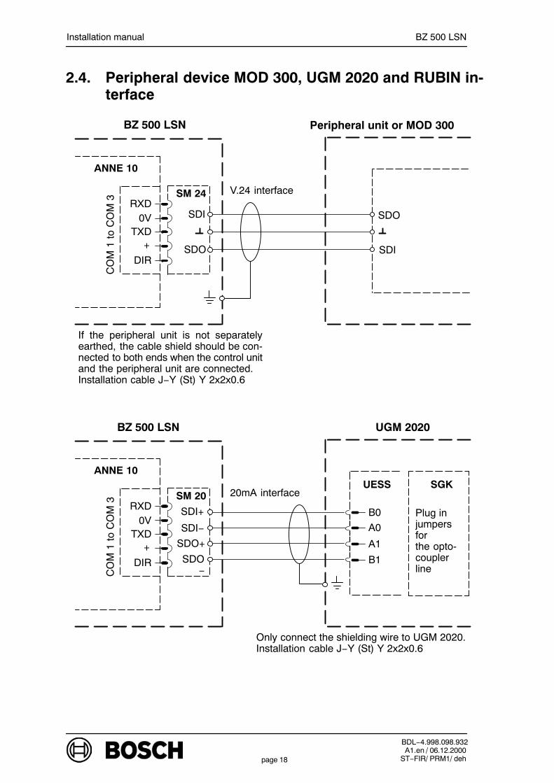
2.4. Peripheral device MOD 300, UGM 2020 and RUBIN in-terface
SDO
SDI
V.24 interface
If the peripheral unit is not separatelyearthed, the cable shield should be con-nected to both ends when the control unitand the peripheral unit are connected. Installation cable J−Y (St) Y 2x2x0.6
BZ 500 LSN
SDI
SDO
ANNE 10
SM 24
CO
M 1
to C
OM
3 RXD0V
TXD+
DIR
20mA interface
UGM 2020
Only connect the shielding wire to UGM 2020. Installation cable J−Y (St) Y 2x2x0.6
B0
A0
A1
B1
SGKUESS
Plug in jumpersforthe opto-couplerline
BZ 500 LSN
SDI+
SDI−
SDO+
SDO−
ANNE 10
SM 20
CO
M 1
to C
OM
3 RXD0V
TXD+
DIR
Peripheral unit or MOD 300

Installation manual BZ 500 LSN
BDL−4.998.098.932A1.en / 06.12.2000
ST−FIR/ PRM1/ dehpage 19
20mA interface
RUBIN
Only connect the shielding wire to RUBIN Installation cable J−Y (St) Y 2x2x0.6
BZ 500 LSN
SDI+
SDI−
SDO+
SDO−
ANNE 10
SM 20
CO
M 1
to C
OM
3 RXD0V
TXD+
DIR
RUBIN
OVS
SDO−
SDO+
SDI−
SDI+

Installation manual BZ 500 LSN
BDL−4.998.098.932A1.en / 06.12.2000
ST−FIR/ PRM1/ dehpage 20
3. Coding
3.1. ANNE 10 connections board
Remove jumperBR1/BR2 whenATE 100 LSN isconnected
Control voltage
Jumper for automaticalstarting the charge pro-cess when battery vol-tage 10,5 Volt
1 M
IN15
MIN
EXT INT
ANLAGE EIN
(STROM)
B1B2
24V 12V
UE
SD
ANNE 10
Battery−test interval
Batterie−Prüfzeit
PTK
LADE START
DOWN LOAD
AUS EIN
SwitchoverINT: without PTK
trackingngEXT: with PTK
tracking
Jumper on EIN”load a completelynew program”(not during configu-ration)
Isolating jumperfor switching On/Off the paneland for currentmeasurement
Key depotSD−control12 V24 V (only with
ERWE 10)
Transmission unittransmission unitcontrol12 V24 V (only with
ERWE 10)
PC Anschluß
Sch
nitts
telle
1
COM1
15 Min.1 Min.
3.2. ERSE 10 expansion interfaces
ERSE 10
ZAL1
AN1
EIN AUS
BR1 BR3
To restart completely (resethardware), bridge the two BR1jumper pins for 1 second.
DOWN LOADjumper on ON”load completely new program”(not in the case of configuration).
On Off

Installation manual BZ 500 LSN
BDL−4.998.098.932A1.en / 06.12.2000
ST−FIR/ PRM1/ dehpage 21
3.3. AE 100 LSN display panel
B1B2
ANNE 10
PC port
Notes on the first ATE 100 LSN connection:Jumpers BR1 and BR2 mustalready have been removedwhen the first ATE 100 LSN is connected.
Notes on the second ATE 100 LSN interface connection:In the case of expansion with a second ATE 100 LSN, theconductor tract connection on the first ATE 100 LSNmust be interrupted. No alterations may be made to thesecond ATE 100 LSN.
1. ATE 100 LSN

Installation manual BZ 500 LSN
BDL−4.998.098.932A1.en / 06.12.2000
ST−FIR/ PRM1/ dehpage 22
3.4. TRN panel realy module
D1BAX 12
Rel 1
T 1
BR1
ST1
R1 *) R2 *)
D2BAX 12
Rel 2
BR2
T 2
ST2+12V
BR3 *)
*) R1, R2 and jumper BR3 not fitted.
RA1 RD1 RR1 RA2 RD2 RR2
Jumper assignment plan:
Relay controlFit jumper
BR1Fit jumper
BR2Fit jumper
BR3
Rel 1 from ST1/T1 + − −
Rel 1 + Rel 2 from ST1/T1 + − +
Rel 2 from ST2/T2 − + −
Rel 2 + Rel 1 from ST2/T2 − + +

Installation manual BZ 500 LSN
BDL−4.998.098.932A1.en / 06.12.2000
ST−FIR/ PRM1/ dehpage 23
3.5. RTP Relay panel board
STRA
RE ARA
AOUTD1
+12V
STRB
STRC
STRD
RKAMKAAKA
RE C
D3
RE W
D2
RE D
D4
R2 *)RKBMKBAKB
R3 *)RKCMKCAKC
R4 *)RKDMKDAKD
+12V
AIN
RE A
RE W
RE C
RE D
RB
BOUT
BIN
RC
COUT
CIN
RD
DOUT
DIN
R1 *)
RTP
RC.. NC contact (relay not activated)MK.. Central contactAK.. Make contact (relay activated)
*) R1−R4 not mounted
Installation manual BZ 500 LSN
BDL−4.998.098.932A1.en / 06.12.2000
ST−FIR/ PRM1/ dehpage 24
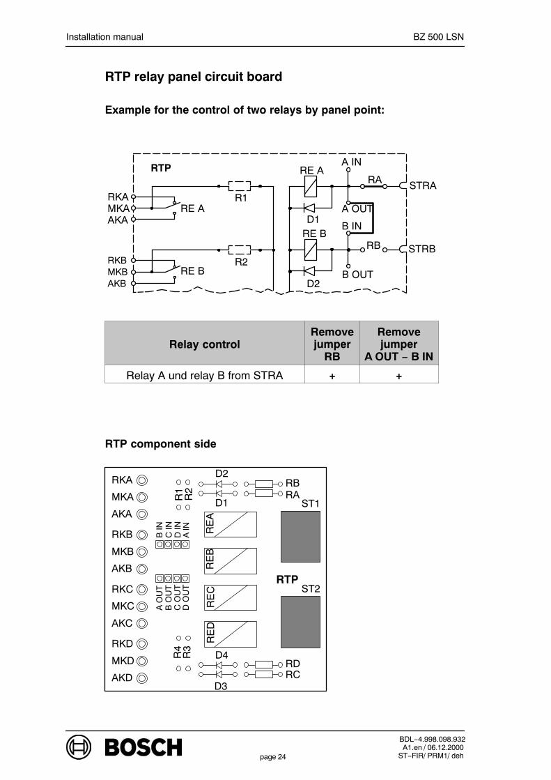
RTP relay panel circuit board
Example for the control of two relays by panel point:
STRA
RE ARA
A OUTD1
STRB
RE B
D2
R2
A IN
RB
B OUT
B IN
R1
RTP
RKAMKAAKA
RKBMKBAKB
RE A
RE B
Relay controlRemovejumper
RB
Removejumper
A OUT − B IN
Relay A und relay B from STRA + +
RTP component side
ST1
ST2
RKA
MKA
AKA
RKB
MKB
AKB
RKC
MKC
AKC
RKD
MKD
AKD
A O
UT
B O
UT
C O
UT
D O
UT
B IN
C IN
D IN
A IN
D2
D1RARB
RCRD
D4
D3
RE
AR
EB
RE
CR
ED
R2
R1
R4
R3
RTP
Installation manual BZ 500 LSN
BDL−4.998.098.932A1.en / 06.12.2000
ST−FIR/ PRM1/ dehpage 25
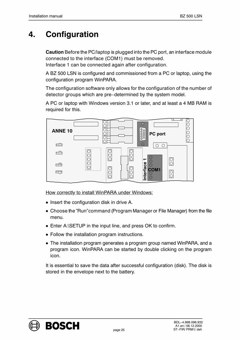
4. Configuration
Caution Before the PC/laptop is plugged into the PC port, an interface moduleconnected to the interface (COM1) must be removed. Interface 1 can be connected again after configuration.
A BZ 500 LSN is configured and commissioned from a PC or laptop, using theconfiguration program WinPARA.
The configuration software only allows for the configuration of the number ofdetector groups which are pre−determined by the system model.
A PC or laptop with Windows version 3.1 or later, and at least a 4 MB RAM isrequired for this.
ANNE 10PC port
Inte
rfac
e 1
COM1
How correctly to install WinPARA under Windows:
Insert the configuration disk in drive A.
Choose the ”Run”command (Program Manager or File Manager) from the filemenu.
Enter A:\SETUP in the input line, and press OK to confirm.
Follow the installation program instructions.
The installation program generates a program group named WinPARA, and aprogram icon. WinPARA can be started by double clicking on the programicon.
It is essential to save the data after successful configuration (disk). The disk isstored in the envelope next to the battery.

Installation manual BZ 500 LSN
BDL−4.998.098.932A1.en / 06.12.2000
ST−FIR/ PRM1/ dehpage 26
5. Setting up
Before connecting the system voltage (with the ”System ON” jumper on ANNE10), it is necessary first to check that all intended modules are properly plugged in, and all ribbon cables are correctly connected.
Caution: The ”system ON” jumper on ANNE 10 has no function in relation to thePSU. The PSU is permanently operational once the power supply has beenconnected on and the line fuse (230V supply) has been inserted (as is thebattery charge).
The program can be restarted on ZALE 10 by bridging the ”RESET” pins.
SYSTEM ON
(POWER)
PC port
COM1
ANNE 10
Monitoring the system while it is in operation
The system configuration is checked each time it is started. If there are defects,the system will not enter the operational status, and a message to this effect willbe issued.
Entering the date/time
It is only possible to set the date/time with service rights.
Sequence of operations:
Press the ”Code” button.
Enter the user code.
Press ”ENTER”
Select the date/time function from the menu (”further functions” button).
Select the digit position to be changed by pressing the ”yes” or ”no” buttons.
Enter the new value on the numeric keyboard, and press ”ENTER” to con-firm.
Exit the date/time function by pressing the ”STOP” button.

Installation manual BZ 500 LSN
BDL−4.998.098.932A1.en / 06.12.2000
ST−FIR/ PRM1/ dehpage 27
6. Notes on maintenance and service
6.1. General
Maintenance and inspection procedures must be carried out at the intervalsspecified by appropriately qualified staff. VDE 0833 specifications areadditionally valid for all work of this kind.
Configuration, comissioning and maintenance are implemented throughsoftware, using a PC or laptop. A PC or laptop with 386 or higher CPU isrecommended.
Hang the operating unit in the maintenance position
The operating unit can be hung in the maintenance position for the purpose ofmaintenance.
System power measuring pointsIt is possible to measure the system power on the ANNE 10 connections board.The ”SYSTEM ON (POWER)” jumper, which is fitted in the factory, must beremoved to do this.
SYSTEM ON
(CURRENT)
Disconnecting jumper for system voltage and currentmeasurement.
PC port
COM1
ANNE 10
6.2. Documents
01 3.002.219.470 1 BZ 500 LSN operating instructions
02 3.002.218.156 1 AHB EMZ/CIE connection handbook
Item Number LE* Name

Installation manual BZ 500 LSN
BDL−4.998.098.932A1.en / 06.12.2000
ST−FIR/ PRM1/ dehpage 28
6.3. Hardware reset
ZALE 10 control unit display
The program can be restarted on ZALE 10 by bridging the ”RESET” pins.Bridging time 1 second.
ZALE 10
”Reset” pins
ERLE 10 NVU expansion
ERLE 10
ZAL1
AN1
”Reset” pins
The program can be restarted on ERLE 10 bybridging the ”RESET” pins.Bridging time 1 second.
ERSE 10 interface expansion
”Reset” pins
The program can be restarted on ERSE 10 bybridging the ”RESET” pins.Bridging time 1 second.
ERSE 10
ZAL1
AN1
Installation manual BZ 500 LSN
BDL−4.998.098.932A1.en / 06.12.2000
ST−FIR/ PRM1/ dehpage 29
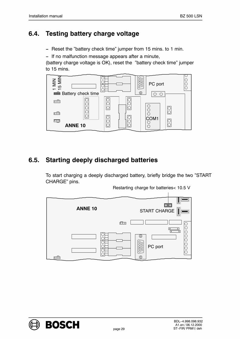
6.4. Testing battery charge voltage
− Reset the ”battery check time” jumper from 15 mins. to 1 min.
− If no malfunction message appears after a minute,(battery charge voltage is OK), reset the ”battery check time” jumper to 15 mins.
1 M
IN15
MIN
Battery check time
PC port
COM1
ANNE 10
6.5. Starting deeply discharged batteries
To start charging a deeply discharged battery, briefly bridge the two ”STARTCHARGE” pins.
Restarting charge for batteries< 10.5 V
ANNE 10 START CHARGE
PC port
Installation manual BZ 500 LSN
BDL−4.998.098.932A1.en / 06.12.2000
ST−FIR/ PRM1/ dehpage 30
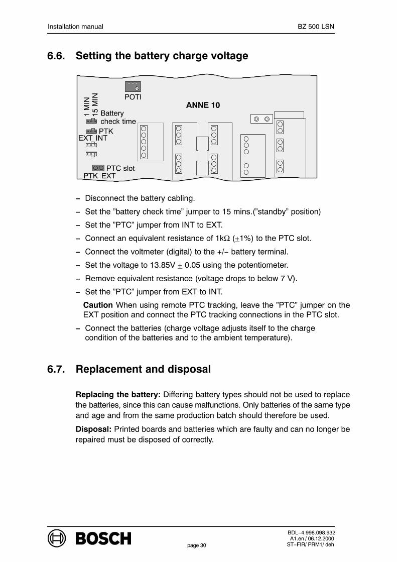
6.6. Setting the battery charge voltage
1 M
IN15
MIN
EXT INT
ANNE 10
PTK
POTI
EXTPTK
Batterycheck time
PTC slot
− Disconnect the battery cabling.
− Set the ”battery check time” jumper to 15 mins.(”standby” position)
− Set the ”PTC” jumper from INT to EXT.
− Connect an equivalent resistance of 1kΩ (+1%) to the PTC slot.
− Connect the voltmeter (digital) to the +/− battery terminal.
− Set the voltage to 13.85V + 0.05 using the potentiometer.
− Remove equivalent resistance (voltage drops to below 7 V).
− Set the ”PTC” jumper from EXT to INT.
Caution When using remote PTC tracking, leave the ”PTC” jumper on theEXT position and connect the PTC tracking connections in the PTC slot.
− Connect the batteries (charge voltage adjusts itself to the charge condition of the batteries and to the ambient temperature).
6.7. Replacement and disposal
Replacing the battery: Differing battery types should not be used to replacethe batteries, since this can cause malfunctions. Only batteries of the same typeand age and from the same production batch should therefore be used.
Disposal: Printed boards and batteries which are faulty and can no longer berepaired must be disposed of correctly.
Installation manual BZ 500 LSN
BDL−4.998.098.932A1.en / 06.12.2000
ST−FIR/ PRM1/ dehpage 31
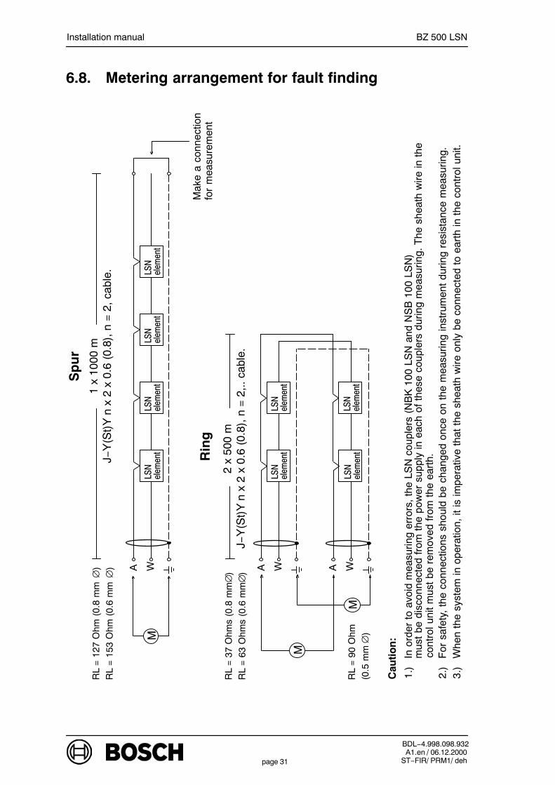
6.8. Metering arrangement for fault findingS
pu
r
RL
= 1
27 O
hm (
0.8
mm
∅)
RL
= 1
53 O
hm (
0.6
mm
∅)
M
A WLSN
element
LSN
element
LSN
element
LSN
element
Mak
e a
conn
ectio
nfo
r m
easu
rem
ent
M
RL
= 3
7 O
hms
(0.8
mm
∅)
RL
= 6
3 O
hms
(0.6
mm
∅)
Rin
g
LSN
element
LSN
element
LSN
element
A W A WM
RL
= 9
0 O
hm(0
.5 m
m∅
)
Cau
tio
n:
1.)
In o
rder
to
avoi
d m
easu
ring
erro
rs,
the
LSN
cou
pler
s (N
BK
100
LS
N a
nd N
SB
100
LS
N)
mus
t be
dis
conn
ecte
d fr
om t
he p
ower
sup
ply
in e
ach
of t
hese
cou
pler
s du
ring
mea
surin
g. T
he s
heat
h w
ire in
the
2.)
For
saf
ety,
the
con
nect
ions
sho
uld
be c
hang
ed o
nce
on t
he m
easu
ring
inst
rum
ent
durin
g re
sist
ance
mea
surin
g.
3.)
Whe
n th
e sy
stem
in o
pera
tion,
it is
impe
rativ
e th
at t
he s
heat
h w
ire o
nly
be c
onne
cted
to
eart
h in
the
con
trol
uni
t.
LSN
element
1 x
1000
m J−
Y(S
t)Y
n x
2 x
0.6
(0.
8), n
= 2
, cab
le.
2 x
500
mJ−
Y(S
t)Y
n x
2 x
0.6
(0.
8), n
= 2
,.. c
able
.
con
trol
uni
t m
ust
be r
emov
ed f
rom
the
ear
th.

Installation manual BZ 500 LSN
BDL−4.998.098.932A1.en / 06.12.2000
ST−FIR/ PRM1/ dehpage 32
7. Technical Data
VdS − Certification No. G 298002
7.1. Dimensions/weight/colour of the control unit
Dimensions (H x W x D) 501 x 443 x 236 mm
Colour
− Casing cover: light grey
− Front components white grey
Weight (full configuration)
− Control unit without battery approx. 17 kg
− Control unit with two batteries approx. 26 kg
7.2. Ambient conditions
Degree of protection IP 40 VDE 0470 Part 1/EN 60529
Class of protection II VDE 0106 Part 1
Surge category II VDE 0804
Environmental classS2, J2, SM2, SE2, E2 VDE 0839 Part 10
EMV noise emission class W EN 50081
EMV noise immunity EN 50082
Pollution severity 2 VDE 0800 Part 6
Environmental class 3K5 EN 60721−3−3
− Temperature 268 K ... 318 K (−5° C ... +45° C)
− Storage temperature 253 K ... 333 K (−20° C ... +60° C)
− Rel. humidity 5 − 95 %
Installation manual BZ 500 LSN
BDL−4.998.098.932A1.en / 06.12.2000
ST−FIR/ PRM1/ dehpage 33
7.3. Power supply
Mains voltage 230 V (−15% ... +10%)
Mains supply cable NYM 3 x 1.5 mm2
Mains frequency 50 Hz
System voltage fuse M 10 A
Operating voltage 11 V ... 15 V (14 V at 20° C)
Consumption in full configuration max. 110 W
Battery capacity max. 2x 12 V/40 Ahin control unit casing
Battery charge voltage is variedaccording to temperature
Duration max. 72 hours
max. power supply unit current 5.4 A(battery charge current + bias current)
Class of protection II
7.4. Transmission equipment control
Principle Current amplification
Control voltageat Ri = 50 Ω ... 1000 Ω: 12 V (24 V with ERWE 10)
Line resistance− at Ri = 50 Ω ... 100 Ω: max. 10 Ω− at Ri = 100 Ω ... 1000 Ω: max. 20 ΩMonitoring Short circuit, wire break
7.5. ERWE 10 voltage transformer
The maximum current output at 28 V is 0.6 A with a current input of approx. 1.4A (12 V).
Installation manual BZ 500 LSN
BDL−4.998.098.932A1.en / 06.12.2000
ST−FIR/ PRM1/ dehpage 34
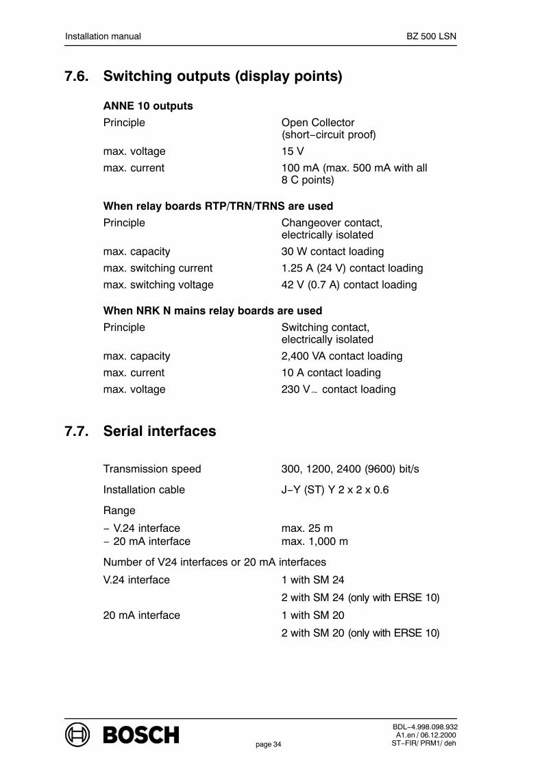
7.6. Switching outputs (display points)
ANNE 10 outputs
Principle Open Collector (short−circuit proof)
max. voltage 15 V
max. current 100 mA (max. 500 mA with all8 C points)
When relay boards RTP/TRN/TRNS are used
Principle Changeover contact, electrically isolated
max. capacity 30 W contact loading
max. switching current 1.25 A (24 V) contact loading
max. switching voltage 42 V (0.7 A) contact loading
When NRK N mains relay boards are used
Principle Switching contact, electrically isolated
max. capacity 2,400 VA contact loading
max. current 10 A contact loading
max. voltage 230 V contact loading
7.7. Serial interfaces
Transmission speed 300, 1200, 2400 (9600) bit/s
Installation cable J−Y (ST) Y 2 x 2 x 0.6
Range
− V.24 interface max. 25 m− 20 mA interface max. 1,000 m
Number of V24 interfaces or 20 mA interfaces
V.24 interface 1 with SM 24
2 with SM 24 (only with ERSE 10)
20 mA interface 1 with SM 20
2 with SM 20 (only with ERSE 10)
Installation manual BZ 500 LSN
BDL−4.998.098.932A1.en / 06.12.2000
ST−FIR/ PRM1/ dehpage 35
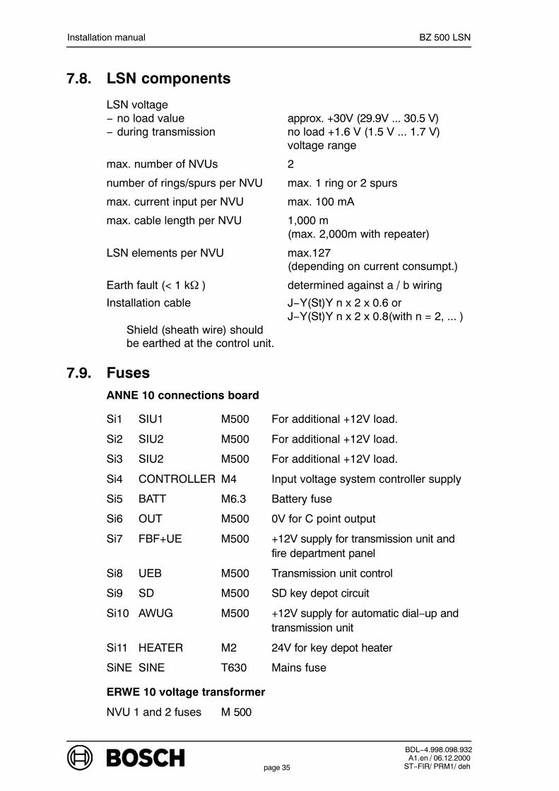
7.8. LSN components
LSN voltage− no load value approx. +30V (29.9V ... 30.5 V)− during transmission no load +1.6 V (1.5 V ... 1.7 V)
voltage range
max. number of NVUs 2
number of rings/spurs per NVU max. 1 ring or 2 spurs
max. current input per NVU max. 100 mA
max. cable length per NVU 1,000 m (max. 2,000m with repeater)
LSN elements per NVU max.127 (depending on current consumpt.)
Earth fault (< 1 k ) determined against a / b wiring
Installation cable J−Y(St)Y n x 2 x 0.6 orJ−Y(St)Y n x 2 x 0.8(with n = 2, ... )
Shield (sheath wire) shouldbe earthed at the control unit.
7.9. FusesANNE 10 connections board
Si1 SIU1 M500 For additional +12V load.
Si2 SIU2 M500 For additional +12V load.
Si3 SIU2 M500 For additional +12V load.
Si4 CONTROLLER M4 Input voltage system controller supply
Si5 BATT M6.3 Battery fuse
Si6 OUT M500 0V for C point output
Si7 FBF+UE M500 +12V supply for transmission unit and fire department panel
Si8 UEB M500 Transmission unit control
Si9 SD M500 SD key depot circuit
Si10 AWUG M500 +12V supply for automatic dial−up andtransmission unit
Si11 HEATER M2 24V for key depot heater
SiNE SINE T630 Mains fuse
ERWE 10 voltage transformer
NVU 1 and 2 fuses M 500
Installation manual BZ 500 LSN
BDL−4.998.098.932A1.en / 06.12.2000
ST−FIR/ PRM1/ dehpage 36
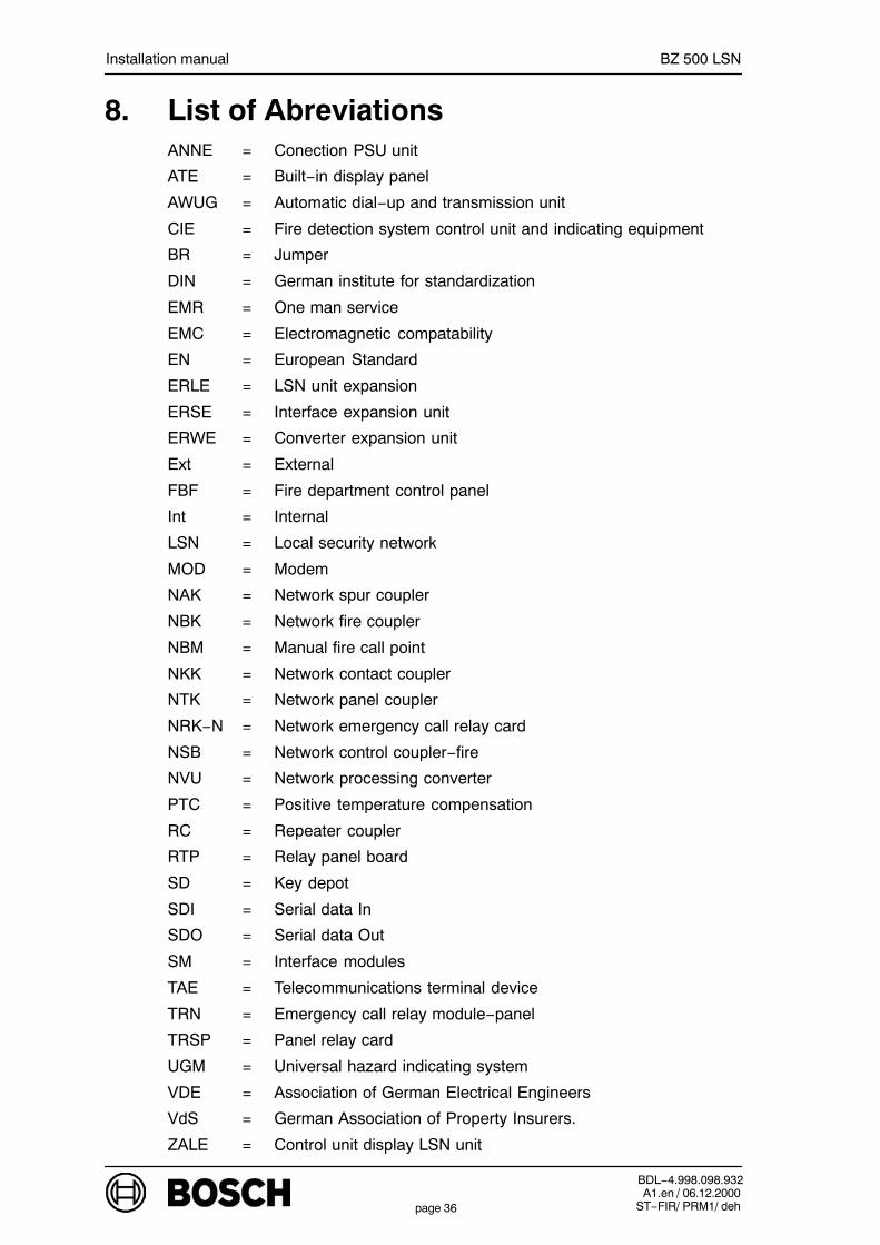
8. List of AbreviationsANNE = Conection PSU unit
ATE = Built−in display panel
AWUG = Automatic dial−up and transmission unit
CIE = Fire detection system control unit and indicating equipment
BR = Jumper
DIN = German institute for standardization
EMR = One man service
EMC = Electromagnetic compatability
EN = European Standard
ERLE = LSN unit expansion
ERSE = Interface expansion unit
ERWE = Converter expansion unit
Ext = External
FBF = Fire department control panel
Int = Internal
LSN = Local security network
MOD = Modem
NAK = Network spur coupler
NBK = Network fire coupler
NBM = Manual fire call point
NKK = Network contact coupler
NTK = Network panel coupler
NRK−N = Network emergency call relay card
NSB = Network control coupler−fire
NVU = Network processing converter
PTC = Positive temperature compensation
RC = Repeater coupler
RTP = Relay panel board
SD = Key depot
SDI = Serial data In
SDO = Serial data Out
SM = Interface modules
TAE = Telecommunications terminal device
TRN = Emergency call relay module−panel
TRSP = Panel relay card
UGM = Universal hazard indicating system
VDE = Association of German Electrical Engineers
VdS = German Association of Property Insurers.
ZALE = Control unit display LSN unit

Installation manual BZ 500 LSN
BDL−4.998.098.932A1.en / 06.12.2000
ST−FIR/ PRM1/ dehpage 37
9. Notes
_____________________________________________________________
_____________________________________________________________
_____________________________________________________________
_____________________________________________________________
_____________________________________________________________
_____________________________________________________________
_____________________________________________________________
_____________________________________________________________
_____________________________________________________________
_____________________________________________________________
_____________________________________________________________
_____________________________________________________________
_____________________________________________________________
_____________________________________________________________
_____________________________________________________________
_____________________________________________________________
_____________________________________________________________
_____________________________________________________________
_____________________________________________________________
_____________________________________________________________
_____________________________________________________________

Installation manual BZ 500 LSN
BDL−4.998.098.932A1.en / 06.12.2000
ST−FIR/ PRM1/ dehpage 38
_____________________________________________________________
_____________________________________________________________
_____________________________________________________________
_____________________________________________________________
_____________________________________________________________
_____________________________________________________________
_____________________________________________________________
_____________________________________________________________
_____________________________________________________________
_____________________________________________________________
_____________________________________________________________
_____________________________________________________________
_____________________________________________________________
_____________________________________________________________
_____________________________________________________________
_____________________________________________________________
_____________________________________________________________
_____________________________________________________________
_____________________________________________________________
_____________________________________________________________
_____________________________________________________________
_____________________________________________________________

Installation manual BZ 500 LSN
BDL−4.998.098.932A1.en / 06.12.2000
ST−FIR/ PRM1/ dehpage 39

Bosch Security Systems130 Perinton ParkwayFairport, New York, 14450, USA
Info−ServiceTelephone: +1 (585) 223 4060Fax: +1 (585) 223 4060