installation manual - costco mat installation manual mat installation manual 3 read these cautions...
TRANSCRIPT

CONTENTSWelcome to PremierMaterials and Cautions
PART 1Inspect the Mat and Sensor
PART 2Control and Electrical Service
PART 3Install the Mat
PART 4Embed the Mat
PART 5Final Wiring and Control
PART 6Troubleshooting Guide
800-276-2419
Radiant MatInstallation Manual
Please be aware that local codes may require this product and/or the thermostatic control to be installed or connected by an electrician.

2 Mat Installation Manual Mat Installation Manual 3
ShieldedPower Leads
Factory connection (between power leads and heating wire).
Welcome to Premier Floor Warming Premier Mat is a floor-warming product for interior floors. It cannot be used for exterior applications, snow melting, or ceilings. Install only below ceramic or porcelain tile, stone, or brick floors, or in a self-leveling mortar bed below vinyl floors, floating wood and laminate floors. Use only cement-based polymer modified mortar. Do not use solvent-based adhesives or pre-mixes because they are not as heat resistant.The heating wire is woven into a special fiber mesh to make rectangular mats. One or more mats wired in parallel at the thermostatic control may be used to warm a tile floor, but care must be taken not to exceed the capacity of the wiring, the control, the breaker, or the Ground Fault CircuitInterrupter (GFCI).
Materials and Tools Needed• Floor-warming mat(s)• Installation DVD and manual (included in the installation kit)• Double-sided tape (included in the installation kit)• Floor-sensing control (with built-in GFCI)• Floor sensor (included with control)• Hot-glue gun• An extra-deep electrical box for the floor-sensing control. Can be single-gang
for one or two mats, or 4” square with a mud ring for more mats. Do not use a “gangable” type box because they are too narrow.
• 12-gauge electrical wiring• Digital ohmmeter (multi-meter) able to measure up to 20,000 ohms (Ω)• Tile installation products (mortar, backer board, tile, etc.)• Trowel (plastic preferred) with 3/8” notches (or greater), and other tiling tools• Various electrical and construction tools (wire stripper, screwdriver, chisel, etc.)• Insulation (for under the floor)• Book or video on electrical wiring techniques• Book or video on installing tile, stone, or other floor coverings
The mat is designed to deliver 12 watts per square foot. The floor temperature attainable is dependent on how well the floor is insulated, the temperature of the floor before start up, and in the case of uninsulated slab applications, the thermal drain of the underlying materials. These are the three most common installations:
1. Wood framing: With the mat installed on a well-insulated wood subfloor, and thin-set mortar and tile on top, most floors can be heated up to 20°F warmer than they would otherwise be.
2. Insulated concrete slab: With the mat installed on an insulated concrete slab (see page 6), and thin-set mortar and tile on top, most floors can be heated up to perhaps 15°F warmer than they would otherwise be.
3. Uninsulated concrete slab: With the mat installed on an uninsulated concrete slab, and thin-set mortar and tile on top, most floors can be heated up to perhaps 10°–15°F warmer than they would otherwise be.
Please consult the factory if there are questions regarding the surface temperature that can be expected from the mat in any particular construction.
Woven Fiber Mesh Tape
Heating Wire
4” squareelectrical boxPower
supply Single gangmud ring
Mat power lead
Floor-warming mat
Tile, stone, or laminate floor covering
Thin-set, thick-set, thin-slab, or self-leveling mortar bed
Sensor installed in floor(equidistant between two heating elements)
Power leadconduitSensor wireconduit(optional)
Bottom platecut outs
General layout of the Mat installation. For details, consult this manual or call toll-free 1-800-276-2419.

2 Mat Installation Manual Mat Installation Manual 3
Read these cautions carefully before beginning the installation.
NEVER:NEVER install the mat under carpet, wood, vinyl, or other non-masonry flooring withoutembedding it in thin-set, thick-set, or self-leveling mortar.
NEVER install the mat in adhesives or glues intended for vinyl tile or other laminateflooring. It must be embedded in polymer modified cement-based mortar.
NEVER cut the heating wire. The power leads can be cut shorter, if necessary, but notremoved completely.
NEVER bang a trowel on the mat/wire to remove excess mortar from the trowel.
NEVER cut the mats to make them shorter. Only the fiber mesh can be cut to make turnsor to help make the mat fit a particular area.
NEVER attempt to repair the heating wire if it is damaged. Contact the factory forinstructions before proceeding.
NEVER splice one mat heating wire to another mat heating wire to make a longer mat.Multiple mats must be connected in parallel in a junction box or to the control.
NEVER install one mat on top of another or overlap the mat on itself. This will causedangerous overheating.
NEVER forget to install the floor sensor.
NEVER install the mats over expansion joints in the mortar or slab unless an appropriateantifracture membrane is installed per Tile Council of America (TCA) recommendations.
NEVER install mats under cabinets or other built-ins, or in small closets. Excessive heat willbuild up in these small spaces, and the mat can be damaged by fasteners (nails,screws, etc.) used to install built-ins.
NEVER remove the nameplate label from the mat power leads.
NEVER install Premier mats in any walls.
ALWAYS:ALWAYS completely embed the heating wire and factory connection in mortar.
ALWAYS enter mat and sensor resistance readings in the Mat and Sensor Resistance Log(see page 4) before, during, and after the installation process.
ALWAYS pay close attention to voltage and amperage requirements of the breaker, thecontrol, and the mat. For instance, do not supply 240 VAC to 120-VAC mats orcontrols.
ALWAYS make sure all electrical work is done by qualified persons in accordance with localbuilding and electrical codes, and the National Electrical Code (NEC), especiallyArticle 424, Part IX of the NEC, ANSI/NFPA 70, and Section 62 of CEC Part I.
ALWAYS use copper only as supply conductors.
ALWAYS affix the warning label (included with your mat) to the control cover plate orother location where it is easily noticed in the area containing the mat.
ALWAYS seek help if a problem arises. If ever in doubt about the correct installationprocedure to follow, or if the product appears to be damaged, the factory mustbe contacted before proceeding with the installation.Call 1-800-276-2419 if there are any questions or problems regarding the installation of the mat or its related electrical components.
NEVER cut the heating wire.
NO!
NEVER bang a trowel on the mat or the heating wire to remove excess mortar. The heating wire can be damaged or severed by this practice.
NO!
Make sure sensor, factory splices and all heating cables are embedded in the floor mortar. Never in a wall or through the floor.
4 Mat Installation Manual Mat Installation Manual 5PART 1: Inspect the Mat and Sensor
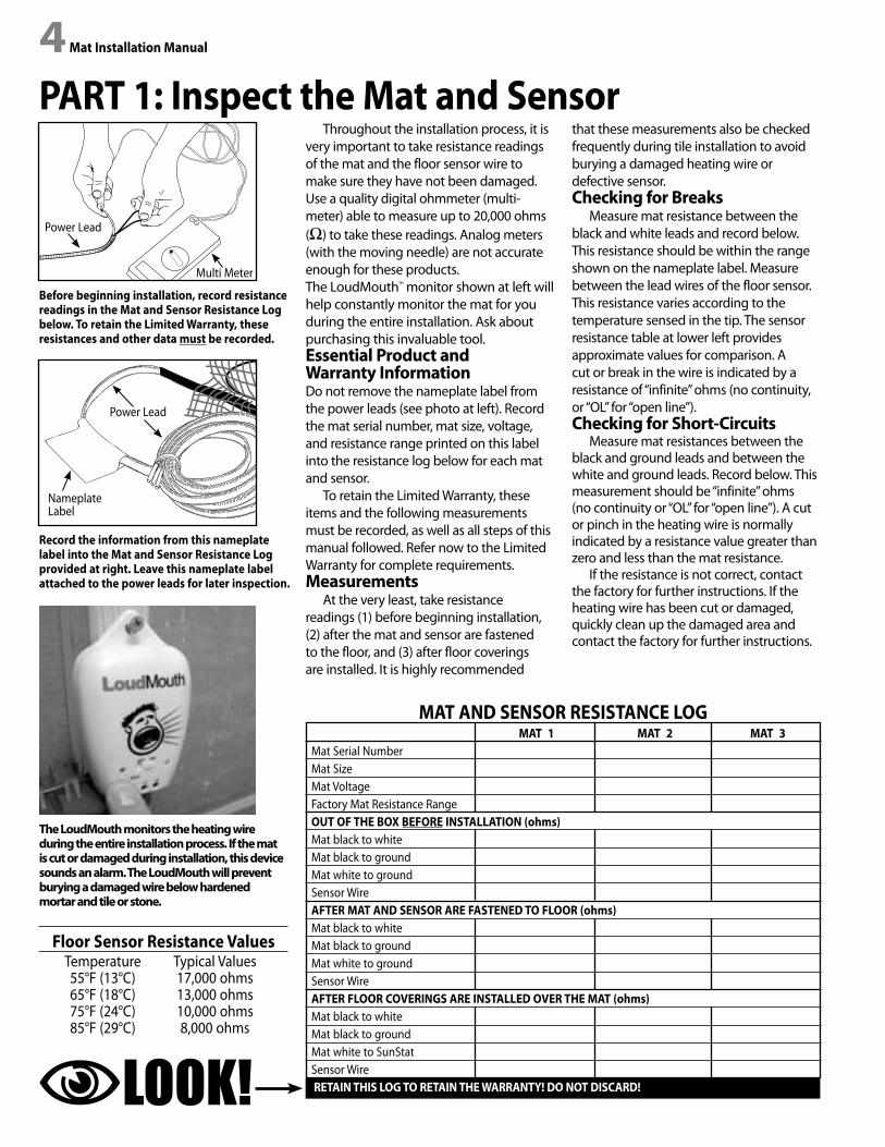
Before beginning installation, record resistance readings in the Mat and Sensor Resistance Log below. To retain the Limited Warranty, these resistances and other data must be recorded.
Record the information from this nameplate label into the Mat and Sensor Resistance Log provided at right. Leave this nameplate label attached to the power leads for later inspection.
Floor Sensor Resistance Values Temperature Typical Values 55°F (13°C) 17,000 ohms 65°F (18°C) 13,000 ohms 75°F (24°C) 10,000 ohms 85°F (29°C) 8,000 ohms
Throughout the installation process, it is very important to take resistance readings of the mat and the floor sensor wire to make sure they have not been damaged. Use a quality digital ohmmeter (multi-meter) able to measure up to 20,000 ohms (Ω) to take these readings. Analog meters (with the moving needle) are not accurate enough for these products.The LoudMouth™ monitor shown at left will help constantly monitor the mat for you during the entire installation. Ask about purchasing this invaluable tool.Essential Product andWarranty InformationDo not remove the nameplate label from the power leads (see photo at left). Record the mat serial number, mat size, voltage, and resistance range printed on this label into the resistance log below for each mat and sensor.
To retain the Limited Warranty, these items and the following measurements must be recorded, as well as all steps of this manual followed. Refer now to the Limited Warranty for complete requirements.Measurements
At the very least, take resistance readings (1) before beginning installation, (2) after the mat and sensor are fastened to the floor, and (3) after floor coverings are installed. It is highly recommended
that these measurements also be checked frequently during tile installation to avoid burying a damaged heating wire or defective sensor.Checking for Breaks
Measure mat resistance between the black and white leads and record below. This resistance should be within the range shown on the nameplate label. Measure between the lead wires of the floor sensor. This resistance varies according to the temperature sensed in the tip. The sensor resistance table at lower left provides approximate values for comparison. A cut or break in the wire is indicated by a resistance of “infinite” ohms (no continuity, or “OL” for “open line”).Checking for Short-Circuits
Measure mat resistances between the black and ground leads and between the white and ground leads. Record below. This measurement should be “infinite” ohms (no continuity or “OL” for “open line”). A cut or pinch in the heating wire is normally indicated by a resistance value greater than zero and less than the mat resistance.
If the resistance is not correct, contact the factory for further instructions. If the heating wire has been cut or damaged, quickly clean up the damaged area and contact the factory for further instructions.
MAT 1 MAT 2 MAT 3Mat Serial NumberMat SizeMat VoltageFactory Mat Resistance RangeOUT OF THE BOX BEFORE INSTALLATION (ohms)Mat black to whiteMat black to groundMat white to groundSensor WireAFTER MAT AND SENSOR ARE FASTENED TO FLOOR (ohms)Mat black to whiteMat black to groundMat white to groundSensor WireAFTER FLOOR COVERINGS ARE INSTALLED OVER THE MAT (ohms)Mat black to whiteMat black to groundMat white to SunStatSensor Wire RETAIN THIS LOG TO RETAIN THE WARRANTY! DO NOT DISCARD!
MAT AND SENSOR RESISTANCE LOG
The LoudMouth monitors the heating wire during the entire installation process. If the mat is cut or damaged during installation, this device sounds an alarm. The LoudMouth will prevent burying a damaged wire below hardened mortar and tile or stone.
LOOK!
Nameplate Label
Power Lead
Power Lead
Multi Meter

4 Mat Installation Manual Mat Installation Manual 5PART 2: Control and Electrical Service
Do not perform any electrical work unless qualified to do so. Contact the factory with any additional questions before beginning the installation.The Control
Use a SunStat floor-sensing control to directly regulate the floor temperature where the mat(s) are placed. The control has its own “ground fault protection” (GFCI) which will guard against electrical hazards in case the mats are damaged. The control handles up to 150 sq. ft. (15amps total), and comes with its own floor sensor that must be installed to operate correctly.Getting Started
Find a good place for the control, preferably on an interior wall, and measure 54” to 60” above the floor. Make sure it is not located in a confined space where airflow is restricted. Each mat has a 10’-long power lead. Locate the control within reach of the mat power lead. Mount to the stud an extra-deep, single-gang electrical box (for one or two mats), or mount a 2-1/8” deep, 4” square box (for more mats) with a single-gang mud ring, according to local code requirements. If the control box must be mounted in a location that is too far to reach with the power lead wires, it will be necessary to mount a junction box where the lead wires can be terminated. Use a standard junction box with a cover, mounting it below the floor, in the attic, or in another easily accessible location. It must remain easily accessible and not located behind a wall, cabinet, or similar obstruction. Then use 12-gauge NM type or other accepted electrical wiring to connect from the junction
box to the control box.New construction. To accommodate
installation of up to three mats, it is recommended that a 3/4” conduit be installed from the box to the bottom plate directly below to contain the mat power leads. (See Appendix for connecting multiple mats). Drill two holes in the top and two corresponding holes in the side of the plate to receive the conduit. One hole is for routing the power leads, and the other is for the floor-sensor wire. Fasten the conduit to the stud with conduit strap.
Existing construction. For a remodeling project, conduit may not be required for the mat power leads, especially for a wall that is already covered. Check the local code.Wiring
It is recommended that the system be installed on its own dedicated circuit, directly from the circuit breaker panel. However, small systems may be able to tap into an existing circuit. Make sure there is adequate capacity for the mat(s) as well as any appliances (such as a hair dryer) that might use the same circuit. The mat(s) should not be installed on a circuit with lighting or fans (exhaust fan, hot tub, etc.) due to possible interference problems which can cause the GFCI on the control to false-trip.
Install 12-gauge insulated electrical wire to the control boxes following all local codes. Leave 6” to 8” of extra wire at the control box, but do not energize the circuit.
Remember: The heating wire must never be cut shorter. The power leads may be cut shorter, if necessary, but never removed completely. Multiple mats are to be connected in parallel not in series (see Appendix).
Conduit enclosing shielded power leads.
Sensor wire enclosed in optional conduit.
Sensor wire
Power lead conduit
Power lead conduit
Sensor wireconduit
Mat Amperage Requirements120 VAC 2’ Wide Mats
Mat Amp ResistanceSize Draw Range30” x 5’ 1.3 84-10230” x 7’ 1.8 61-7530” x 9’ 2.3 47-5830” x 11’ 2.8 37-4630” x 13’ 3.3 30-3730” x 15’ 3.8 24-29

6 Mat Installation Manual Mat Installation Manual 7
Select Type of ConstructionThe cross sections on these pages
depict types of construction (slab vs. frame floor) and applications commonly used in the installation of the mat. Choose the best installation detail for the particular construction and application.
Insulation. In new slab construction, it is highly recommended that foam insulation be installed under and around the slab to prevent loss of radiant heat into the surrounding soil.
In existing construction where insulation under the slab is absent, it is strongly recommended that a layer of insulating material be attached to the slab prior to the installation of the mat.
Cork, for example, possesses a minimal R value that will help keep the radiant heat at the floor surface. Consult the cork manufacturer regarding proper application and attachment of the cork to the concrete slab.
Antifracture membrane. While optional, it is recommended that an antifracture membrane (crack isola-tion membrane) be installed directly to the slab or the self-leveling mortar layer underneath the tile. This flexible layer reduces the chance of minor stress and fracturing in the slab from being transmitted upward to the tile.
Reinforcement. To further strengthen the floor, consider laying a 1-1/4” to 2” mudbed, reinforced with metal or plastic lath, directly onto the optional antifracture membrane. Then install the mat(s).
PART 3:Install the Mat
Tile or stone
Thin-set
TCA RH115
Floor-warming mat
Antifracture membrane(optional)
Existing/new slab
Tile or stone
Thin-set
TCA F114
Floor-warming mat
Antifracture membrane(optional)
Existing/new slab
1-1/4” to 2” mudbed
Metal/plastic lath reinforcement
Tile or stone
Thin-set
TCA F205
Antifracture membrane (optional)
Existing/new slab
Self-leveling thin-set
Floor-warming mat
Tile or stone
Thin-set
TCA F135
Floor-warming mat
Existing/new slab
Insulating Material(i.e., 1/2” cork. Consult corkmanufacturer regardingattachment to concrete slab.)

6 Mat Installation Manual Mat Installation Manual 7In framed-floor construction, the
two primary concerns are insulation and floor rigidity. Without proper insulation, radiant heat leaks into the joist spaces. And unless the plywood subfloor is properly reinforced, stresses in the subflooring can cause unsightly cracking in the tile floor.
Insulation. The use of insulation in the joist spaces dramatically enhances the performance and efficiency of the floor-warming system. Insulation with an R value of 19 will be sufficient for most regions, while in more temperate areas R-11 will suffice.
Do not install rigid insulation layers directly above or below backer board or mortar. If possible, install insulation as shown in the diagrams at right.
Reinforcement. There are several options for strengthening the subfloor:
1. Add 3/4”-thick plywood on top of the existing subfloor.
2. Pour a 1/4”–1/2”-thick layer of self-leveling mortar over the existing subfloor, then install the mat on top of the mortar layer.
3. Install a quality cementitious backer board or fiber cement underlayment over the subfloor. Then lay the mat and tile.
Antifracture membrane. While optional, it is recommended that an antifracture membrane (crack isola-tion membrane) be installed to re-duce the chance of minor stress and fracturing in the subflooring from being transmitted upward to the tile. If an antifracture membrane is used, install the mat above the membrane, unless otherwise recommended by the membrane manufacturer.
In place of an antifracture mem-brane, an uncoupling system can be installed to prevent deflection in the subfloor from affecting the tile surface
Tile or stone
Thin-set
TCA RH130
Floor-warming mat
Floor joist
Antifracture membrane (optional)
Plywood (per TCNA recommendations)
Existing plywood subfloor
Insulation (per IRC recommendations)
Tile or stone
Thin-set
TCA RH135
Floor-warming mat
Floor joist
Antifracture membrane (optional)
Backer board
Existing plywood subfloor
Insulation (per IRC recommendations)
Tile or stone
Thin-set
TCA F147
Uncoupling system (per uncouplingmanufacturer’s recommendations)
Floor joist
Thin-set
Floor-warming mat
Existing plywood subfloor
Insulation (per IRC recommendations)
Tile or stone
Thin-set
TCA F141
Floor-warming mat
Floor joist
Self-leveling thin slab
Antifracture membrane (optional)
Existing plywood subfloor
Insulation (per IRC recommendations)

8 Mat Installation Manual Mat Installation Manual 9Mortar Beds
The mats can be installed in three types of mortar beds: thin-set or thick-set mortar beds 3/8” to 1” thick, and self-leveling mortar beds 1/4” to 1/2” thick.
Thin-set Mortar Beds. If the mat will be placed directly onto the slab, or if backer board or plywood reinforcement is used on a plywood subfloor, first install the mat then apply the thin-set mortar bond coat directly over the mat and lay the tile.
Thick-set Mortar Beds. If a thicker mortar bed is used to strengthen the floor, the mat can be installed under either the mortar bed (also known as “dry-set”) or under the mortar bond coat directly below the tile or stone. In a thick-set application, the mat is generally installed above the mortar bed, but before the thin-set bond coat. Thick mortar beds of this type require the use of a reinforcing mesh or lath. If plastic lath is used instead of the typical metal lath, the mat can be installed before pouring the self-leveling mortar bed.
CAUTION:If metal lath is used in the mortar bed, do not allow the mat to come in direct contact with the lath. Damage to the heating wire could result.
Self-leveling Mortar Beds. Self-leveling mortar beds are appropriate if installing non-masonry floor coverings such as engineered wood, vinyl, laminate, or carpet. Attach the mat to the slab or subfloor, then pour a 1/4”–1/2”-thick layer of self-leveling mortar over the mat according to manufacturer’s specifications. Install the floor coverings after the mortar has cured.
It is strongly recommended that tile and stone flooring be installed according to manufacturer’s recommendations, TCNA guidelines, and ANSI specifications. Follow industry and manufacturer’s recommendations when installing non-masonry floor coverings, such as hardwood, vinyl, laminate, or floating floors.
Other ConsiderationsExpansion joints. In slab or mortar
applications, do not install the mats
through an expansion joint unless an appropriate antifracture membrane is installed per Tile Council of America (TCNA) recommendations. If not using an antifracture membrane, install the mats right up to the joint, if necessary, but not through the joint.
Mosaic tile. When laying mosaic tile, first embed the heating mat in the appropriate mortar bed as shown in the diagrams on the previous pages, and allow to cure per manufacturer’s instructions. Then thin-set the mosaic tile according to typical practice.
REMEMBER:If in doubt about any aspect or phase of the installation, consult with building professionals and/or the manufacturer regarding specific installation details before beginning.
Prepare the FloorThe floor must be completely swept
and damp-mopped to remove all nails, wood fragments, dirt, and other construction debris. Make absolutely sure there are no objects on the floor or fasteners penetrating the floor that might damage the heating wire.
Study the Factory-supplied Items and the Design
Make sure all the correct materials have been purchased. A general list of materials is found at the beginning of this manual.
Study the design carefully before installation. Determine exactly which areas of the floor will be heated. Review the location of the control and where
the mat begins and ends, as well as the general layout pattern.
Next, roll out the mat to make sure it fits the space allocated and the power leads reach the electrical box. Install the mat 4” to 6” away from walls, showers, tubs, and wax toilet rings, but install right up to vanities and counter areas, especially kick spaces. Heat will radiate only about 1-1/2” to 2” from the heating wire. The mat may be installed close to the wall, if needed, but never where a baseboard nail may damage the heating wire.
REMEMBER:NEVER install mats under cabinets or other built-ins, or in small closets. Excessive heat will build up in these small spaces, and the mat can be damaged by the fasteners (nails, screws, etc.) used to install the built-ins. And . . .NEVER cut or shorten the heating wire to make it fit the space. This will cause dangerous overheating and will void the warranty!
Install the Power Leads and Sensor Wire
In new construction, feed a steel fish tape, spare wire, cord, or string through the conduit installed earlier, and pull the power leads back through the conduit up to the electrical box. If using the floor-sensing control, feed the sensor wire down from the electrical box to the floor, but do not place the sensor wire and power leads in the same conduit.
Place matunder the
kick space forwarm toes!
Place mat 4” to 6” fromthe wax toilet ring andbeneath the pedestal
front edge and tile.
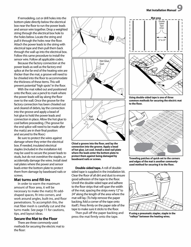
8 Mat Installation Manual Mat Installation Manual 9If remodeling, cut or drill holes into the
bottom plate directly below the electrical box near the floor to run the power leads and sensor wire together. Drop a weighted string through the electrical box hole to the holes below. Locate the string and pull it through the holes near the floor. Attach the power leads to the string with electrical tape and then pull them back through the wall up into the electrical box. Follow this same procedure to install the sensor wire. Follow all applicable codes.
Because the factory connection at the power leads as well as the factory end splice at the far end of the heating wire are thicker than the mat, a groove will need to be chiseled into the floor to accommodate the thickness of these items. This will prevent potential “high spots” in the floor.
With the mat rolled out and positioned onto the floor, use a pencil to mark where the power leads will lay along the floor over to the wall. Once the groove for the factory connection has been chiseled out and cleared of debris, lay the connection into the groove and apply a bead of hot glue to hold the power leads and connection in place. Allow the hot glue to cool before proceeding. (The groove for the end splice will need to be made after the mat(s) are in their final position and secured to the floor.)
Be sure to protect the wires against damage where they enter the electrical box. If needed, insulated electrical staples (included in the installation kit) may be used to secure the power leads to studs, but do not overdrive the staples, or accidentally damage the wires. Install steel nail plates where the power and sensor leads enter the bottom plate to protect them from damage by baseboard nails or screws. Mat turns and fill-ins
In order to warm the maximum amount of floor area, it will be necessary to make the mat(s) fit odd-shaped spaces, fit into corners, and work around angles, built-ins, and floor penetrations. To accomplish this, the mat fiber mesh is carefully cut and the turns made. See page 11 for cautions, tips, and layout ideas.
Secure the Mat to the FloorThere are three commonly-used
methods for securing the electric mat to the floor:
Double-sided tape. A roll of double-sided tape is supplied in the installation kit. Clear the floor of all dirt and dust to ensure good adhesion of the tape to the floor. Unroll the double-sided tape and adhere to the floor strips that will span the width of the mat, spacing the strips every 12” to 24” along the length of the area where the mat will lay. (To help remove the paper backing, fold a corner of the tape onto itself). Press firmly on the paper side of the tape to make sure it sticks to the floor.
Then pull off the paper backing and press the mat firmly onto the tape.
Chisel a groove into the floor, and lay the connection into the groove. Apply a bead of hot glue. Let cool. Install a steel nail plate where the leads enter the bottom plate to protect them against being damaged by baseboard nails or screws.
Using double-sided tape is one of three common methods for securing the electric mat to the floor.
If using a pneumatic stapler, staple in the “valleys” between the heating wires.
Mat areaDoubleSidedTapestrips
12” to 24”
Hot Glue Gun
Nail Plate
Troweling patches of quick-set to the corners and edges of the mat is another commonly-used method for securing it to the floor.

10 Mat Installation Manual Mat Installation Manual 11
Chisel a groove into the floor for the end splice. Lay the splice into the groove and hot glue into place. Let cool before proceeding.
To recess the sensor into the floor, cut away a small area of the mat mesh and chisel out a shallow pocket for the sensor. Thread the sensor wire 6”–12” into the weave of the mat and center the sensor tip exactly between two of the heating wires. Hot glue the sensor tip into place.
Pneumatic staples. If stapling the mat to the floor, it is recommended that 3/8” x 1/4” chisel point staples be used. Initially attach the mat every 2 to 3 ft. on either side of the mat, stapling in the “valleys” between the heating wires. By stapling in the “valleys,” it will be easier to pull up and reposition the mat, if necessary. When satisfied with the layout, go back and put in a staple every 12” to secure the mat. Proceed slowly and be very careful not to staple the heating wire.
Quick-set. Place the mat into position on the floor. Use the double-sided tape to hold the mat in place, then trowel small patches of quick- set to the corners and edges of the mat. When dry (follow manufacturer’s instructions), the mat will be permanently adhered to the floor.
Note: Regardless of the method used to attach the mat to the floor, make sure to stretch the mat tightly and pull out the slack as it is being secured to the floor. The tighter the mat, the easier it will be to apply the thin-set over it.Recess the end splice.
With the mat secured to the floor, use a pencil to mark the spot where the end splice will be recessed. Chisel out the groove for the end splice, and hot glue the splice into the groove. Let cool before proceeding.Install the Sensor intothe Floor
Like the factory connection and end splice, the floor sensor tip will also need to be recessed into the floor. With the mat positioned and secured to the floor, locate the precise spot where the sensor will go and “thread” the sensor 6”–12” into the weave of the mat mesh, making sure to place the sensor tip exactly between two of the heating wires. Installing the sensor tip too close to either of the heating wires will send an exaggerated temperature reading to the thermostatic control.
At the spot where the sensor tip will be recessed into the floor, use a utility knife to cut out a small amount of the fiber mesh. Chisel out a shallow pocket
for the sensor. Be very careful not to damage the heating wire or the sensor wire with the utility knife or chisel. Hot glue the sensor tip into the pocket chiseled out for it.
Conduct a resistance check! With the mat(s) secured to the floor and the sensor installed into the floor, con- duct another resistance check of both the mat and the sensor with a digital ohmmeter, and record these readings in the Mat and Sensor Resistance Log on page 4. Failure to take and record these resistance readings will void the warranty!
Take photos of the installation! This will provide a record of how and where the mats were laid onto the floor.
If the flooring will not be installed immediately, cover the mat with corrugated box material or plywood for short-term protection. Never leave the mat unprotected.
Knife
Hot Glue Gun
End Splice
Hot Glue Gun
Chisel

10 Mat Installation Manual Mat Installation Manual 11Mat Turns and Fill-in Techniques
Carefully cut the woven mat mesh to effect turns. NEVER cut, nick, or otherwise damage the heating wire.
When making mat turns, make sure the mats are fastened to the floor such that the heating wires are no closer than 2” from each other. NEVER overlap or cross one heating wire or mat over another; dangerous overheating will occur.
Roll-over Turn 90° or Flip Turn
180° or Back-to-Back TurnFill-in Technique
Cut
Rollover
Rotate Rotate
Rotate
Flip
Removemat mesh
Fill loose wire indesired area
Move remaining matup to new positon
Cut
Cut
Cut
Flip
Roll-over Turn 90° or Flip Turn
180° orBack-to-Back Turn
Fill-in Technique
Cut mat Rotate 90°
Cut mat Rollover
Cut mat
Flip matover
Rotate 90°
Mat meshremoved
Use clips or hot glue to attach wire to the oor.
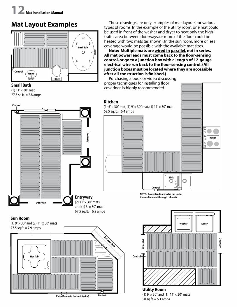
12 Mat Installation Manual Mat Installation Manual 13Mat Layout Examples
Small Bath(1) 11' × 30" mat27.5 sq.ft. = 2.8 amps
Vanity
Toilet
Bath Tub
Control
Control
Range
Sink
Kitchen(1) 5' × 30" mat, (1) 9' × 30" mat, (1) 11' × 30" mat62.5 sq.ft. = 6.4 amps
Entryway(2) 11' × 30" mats and (1) 5' × 30" mat67.5 sq.ft. = 6.9 amps
Control
Doorway
Doorw
ay
Sun Room(1) 9' × 30" and (2) 11' x 30" mats77.5 sq.ft. = 7.9 amps
Hot Tub
Outside Deck
Patio Doors (to house interior) Control
Utility Room(1) 9' × 30" and (1) 11' × 30" mats50 sq.ft. = 5.1 amps
Doorw
ay
Doorw
ay
Washer Dryer
Control
NOTE: Power leads are to be run under the subfloor, not through cabinets.
These drawings are only examples of mat layouts for various types of rooms. In the example of the utility room, one mat could be used in front of the washer and dryer to heat only the high-traffic area between doorways, or more of the floor could be heated with two mats (as shown). In the sun room, more or less coverage would be possible with the available mat sizes.
Note: Multiple mats are wired in parallel, not in series. All mat power leads must come back to the floor-sensing control, or go to a junction box with a length of 12-gauge electrical wire run back to the floor-sensing control. (All junction boxes must be located where they are accessible after all construction is finished.)
Purchasing a book or video discussing proper techniques for installing floor coverings is highly recommended.

12 Mat Installation Manual Mat Installation Manual 13PART 4: Embed the Mat
While embedding the mat, periodically check mat resistance to make sure the heating wire has not been damaged. If the mat has been damaged, locate the damaged area and quickly clean away all mortar materials, and call the factory (800-276-2419) for assistance. When finished tiling, take another resistance reading and record it in the resistance log (page 4).Thin-setting Techniques
Consider using a plastic trowel to avoid possible damage to the mat.
One-step application. Directly apply the thin-set onto the mat with a 1/4” x 3/8” notched trowel, and then lay the tile directly onto the thin-set.
Two-step application. Apply the thin-set onto the mat with the flat side of the trowel to fill in the voids of the mat. Then trowel more thin-set with the notched side and set the tile.
Back-butter. Apply thin-set with the flat side of the trowel to fill the void areas of the mat. Then “back-butter” thin-set onto the underside of each tile, comb with the notched side of the trowel, and set the tile.
Double-layer thin-set. Flat trowel thin-set over the entire mat. Let cure. Then trowel fresh thin-set on top of the dry layer, and set the tile. This technique is especially recommended when laying mosaic and other small tile (smaller than 6” x 6”).
Self-leveling mortar. Pour a layer of self-leveling mortar over the mat. Let cure. Then thin-set the tile, stone, or other floor covering over the mortar.
NEVER install nail-down hardwood flooring over the mat. Only floating or glue-down hardwood or laminate flooring is permitted.
NEVER allow the mat to come into direct contact with metal lath reinforcement; the heating wire could be damaged by the lath. The mat and metal lath must be embedded in separate layers of mortar. If using plastic lathing, the mat can be embedded with the plastic lath in a single mortar layer.
WARNING!Do not snag the heating wire with the trowel.NEVER clean the trowel of excess mortar by banging it against the mat. The heating wire, pow er lead, or sensor wire could be damaged or severed!O
ne-s
tep
appl
icat
ion
Two-
step
app
licat
ion
Back
-but
ter
Dou
ble-
laye
rSe
lf-le
velin
g m
orta
rTrowel thin-set onto mat.
Trowel thin-set into voids.
Trowel thin-set into voids.
Trowel thin-set onto mat.Allow it to cure.
Pour mortar onto mat.Allow it to cure.
Lay the tile.
Lay the tile.
Lay the tile.
Lay the small-fomat tile.
Lay the tile.
Trowel new layer of thin-set.
Back-butter tile with thin-setand comb with notched side.
Trowel a second layer.
Trowel a layer of thin-set.
14 Mat Installation Manual Mat Installation Manual 15PART 5: Final Wiring and Control
WARNING!Make certain the power from the breaker box or electrical source is turned off before beginning work.
All electrical work should be performed by qualified persons, according to all national and local building and electrical codes. Review the CAUTIONS on page 3, and study the wiring diagram on page 15 for guidance in making final electrical connections to the control.
In new construction, remember to install a mud ring over the face of the electrical box(es) if using a 4” square box. This must be done before sheet-rock and wall finishes are applied.Make Connections to the Control
Make sure that the power leads and sensor wire have already been fed from the mat up the wall to the control electrical box.
If not already done, install a 12-gauge insulated electrical wire to the control electrical box. Normally, this wire is color-coded for connection: For 120 volt connection, black is line voltage, white is neutral, and ground bare.
Make connections starting with the “line” wires on the control. Connect the black “line” wire from the control to the black wire of the incoming power. Connect the white “line” wire from the control to the white wire of the incoming power.
Now make the “load” connections. Connect the black “load” wire from the control to the black wire(s) coming from the mat(s). Connect the white “load” wire from the control to the white wire(s) coming from the mat(s).
The ground wire(s) from the mat(s) should connect to the ground wire of the incoming power. If using a metal electrical box, install a short piece of ground wire to connect also to the control electrical box.
Finally, insert the sensor wires into the proper terminals on the control.
Before placing the control into the electrical box, lightly tug on the wires to make sure all wires are secure in the wire nuts.
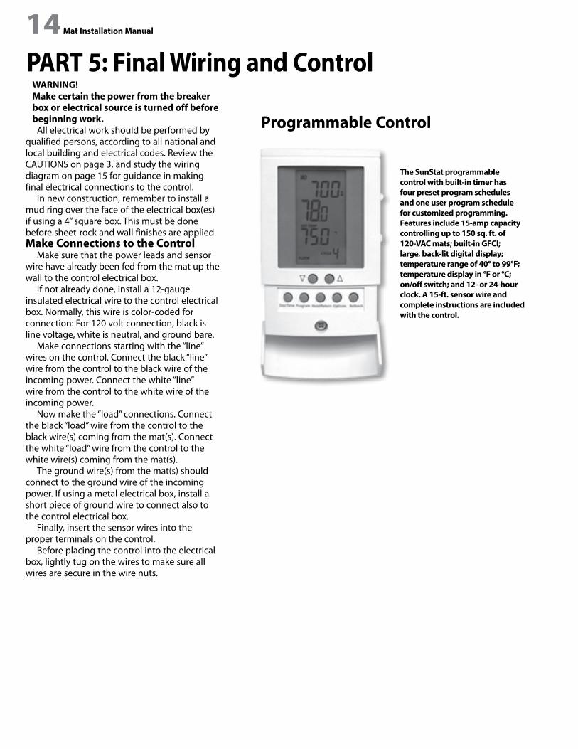
Programmable Control
The SunStat programmable control with built-in timer has four preset program schedules and one user program schedule for customized programming. Features include 15-amp capacity controlling up to 150 sq. ft. of 120-VAC mats; built-in GFCI; large, back-lit digital display; temperature range of 40° to 99°F; temperature display in °F or °C; on/off switch; and 12- or 24-hour clock. A 15-ft. sensor wire and complete instructions are included with the control.
14 Mat Installation Manual Mat Installation Manual 15
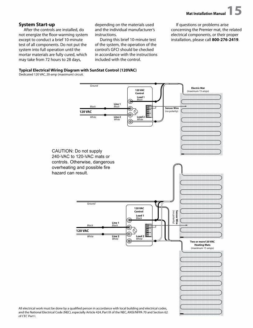
Typical Electrical Wiring Diagram with SunStat Control (120VAC)Dedicated 120 VAC, 20-amp (maximum) circuit.
Ground
Black Black
Black
WhiteWhite White
Line 1
Load 1
Load 2Line 2
120 VACSensor Wire(no polarity)
Electric Mat(maximum 15 amps)120 VAC
Control
Two or more120 VAC
Heating Mats(maximum 15 amps)
Ground
Black Black
Black
WhiteWhite White
Line 1
Load 1
Load 2Line 2
120 VAC
Senso
r Wire
(no
po
larity)
120 VACControl
Ground
Black Black
Black
WhiteWhite White
Line 1
Load 1
Load 2Line 2
120 VACSensor Wire(no polarity)
Electric Mat(maximum 15 amps)120 VAC
Control
Two or more120 VAC
Heating Mats(maximum 15 amps)
Ground
Black Black
Black
WhiteWhite White
Line 1
Load 1
Load 2Line 2
120 VAC
Senso
r Wire
(no
po
larity)
120 VACControl
System Start-upAfter the controls are installed, do
not energize the floor-warming system except to conduct a brief 10-minute test of all components. Do not put the system into full operation until the mortar materials are fully cured, which may take from 72 hours to 28 days,
depending on the materials used and the individual manufacturer’s instructions.
During this brief 10-minute test of the system, the operation of the control’s GFCI should be checked in accordance with the instructions included with the control.
If questions or problems arise concerning the Premier mat, the related electrical components, or their proper installation, please call 800-276-2419.
Ground
Black Black
Black
WhiteWhite White
Line 1
Load 1
Load 2Line 2
120 VACSensor Wire(no polarity)
120 VACSunStat Control
CAUTION: Do not supply 240-VAC to 120-VAC mats or controls. Otherwise, dangerous overheating and possible fire hazard can result.
16 Mat Installation Manual Mat Installation Manual 17
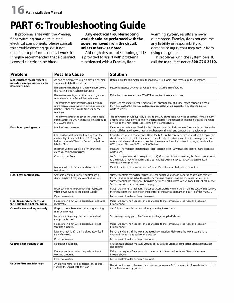
If problems arise with the Premier, floor-warming mat or its related electrical components, please consult this troubleshooting guide. If not qualified to perform electrical work, it is highly recommended that a qualified, licensed electrician be hired.
Any electrical troubleshooting work should be performed with the power removed from the circuit, unless otherwise noted.
Although this troubleshooting guide is provided to assist with problems experienced with a Premier, floor-
warming system, results are never guaranteed. Premier, does not assume any liability or responsibility for damage or injury that may occur from using this guide.
If problems with the system persist, call the manufacturer at 800-276-2419.
PART 6: Troubleshooting Guide
ProblemMat resistance measurement isoutside the range printed on the nameplate label.
Floor is not getting warm.
Floor heats continuously.
Floor temperature shows over 90° F but floor is not that warm.
Control is not working correctly.
Control is not working at all.
GFCI conflicts and false-trips
Possible CauseAn analog ohmmeter (using a moving needle) was used to take the reading.
If measurement shows an open or short circuit, the heating wire has been damaged.
If measurement is just a little low or high, room temperature has affected the resistance.
The resistance measurement could be from more than one mat wired in series, or wired in parallel. Either will provide false resistance readings.
The ohmmeter may be set to the wrong scale. For instance, the 200 K ohms scale measures up to 200,000 ohms.
Mat has been damaged.
GFCI has tripped, indicated by a light on the control. Light may be labeled “GFI”, may be below the words “Stand by”, or on the button labeled “Test”.
Incorrect voltage supplied, or mismatched electrical components used.
Concrete slab floor.
Mats are wired in “series” or “daisy chained” (end-to-end).
Sensor is loose or broken. If control has a digital display, it may indicate “Er3” or “LO”.
Incorrect wiring. The control was “bypassed” when it was wired to the power supply.
Defective control.
Floor sensor is not wired properly, or is located incorrectly.
If a programmable control, the programming may be incorrect.
Incorrect voltage supplied, or mismatched components used.
Floor sensor is not wired properly, or is not working properly.
Loose connection(s) on line side and/or load side of control.
Defective control.
No power is supplied.
Floor sensor is not wired properly, or is not working properly.
Defective control.
An electric motor or a ballasted light source is sharing the circuit with the mat.
SolutionObtain a digital ohmmeter able to read 0 to 20,000 ohms and remeasure the resistance.
Record resistance between all wires and contact the manufacturer.
Make the room temperature 75°–85°F, or contact the manufacturer.
Make sure resistance measurements are for only one mat at a time. When connecting more than one mat to the control, multiple mats must be wired in parallel (i.e., black to black, white to white).
The ohmmeter should typically be set to the 200 ohms scale, with the exception of mats having a rating above 200 ohms on their nameplate label. If the resistance reading is outside the range printed on the nameplate label, contact the manufacturer.
Measure mat resistance. Check for both “open circuit” and “short circuit” as detailed earlier in this manual. If damaged, record resistances between all wires and contact the manufacturer.
Check for loose wire connections. Reset the GFCI on the control or circuit breaker. If it trips again, check for a short circuit in the mat as detailed earlier in this manual. If mat is damaged, record resistance between all wires and contact the manufacturer. If mat is not damaged, replace the GFCI control. Also see “GFCI conflicts” below.
Measure “line” voltage, then measure “load” voltage. Both 120-V mats and controls have black and white leads.
Surface temperatures rise slowly in a slab. If, after 5 to 8 hours of heating, the floor is not warmer to the touch, check for mat damage (see “Mat has been damaged” above). Measure “load” voltage/amperage to mat.
Multiple mats must be connected in “parallel” (or black-to-black, white-to-white).
SunStat controls have a floor sensor. Pull the sensor wires loose from the control and reinsert them. If this does not solve the problem, measure resistance across the sensor wires. For a SunStat control the resistance should be between 17,000 ohms (at 55°F) and 8,000 ohms (at 85°F). See sensor wire resistance values on page 4.
Make sure wiring connections are correct. Consult the wiring diagram on the back of the control, the instructions that came with the control, or the wiring diagram on page 16 of this manual.
Return control to dealer for replacement.
Make sure only one floor sensor is connected to the control. Also see “Sensor is loose or broken” above.
Carefully read and follow control programming instructions.
Test voltage, verify parts. See “Incorrect voltage supplied” above.
Make sure only one floor sensor is connected to the control. Also see “Sensor is loose or broken” above.
Remove and reinstall the wire nuts at each connection. Make sure the wire nuts are tight. Check all connections back to the breaker.
Return control to dealer for replacement.
Check circuit breaker. Measure voltage at the control. Check all connections between breaker and control.
Make sure only one floor sensor is connected to the control. Also see “Sensor is loose or broken” above.
Return control to dealer for replacement.
Electric motors and other electrical devices can cause a GFCI to false-trip. Run a dedicated circuit to the floor-warming system.

16 Mat Installation Manual Mat Installation Manual 17Appendix: Connecting Multiple Mats
Connecting LoudMouth
NOTE: The thermostatic control is not shown in these diagrams in order to simplify them. These diagrams are given only as examples of how to properly connect multiple mats. Care must be taken not to overfill a box. Be sure to use wire nuts that are the correct size for the connections being made. Follow all codes for wiring. If in doubt, consult an electrician.
Illustration showing how to connect three mats at the thermostatic control electrical box.
Illustration showing how to connect multiple mats from
multiple junction boxes at one thermostatic control
electrical box.
Illustrations showing (left) how to connect the LoudMouth monitor to two cables, and (right) how to connect the LoudMouth to three cables. The LoudMouth can monitor no more than three cables simultaneously. Do NOT leave the power leads connected in “series” like this when making final wiring connections; the cables will not heat sufficiently.

18 Mat Installation Manual
Mat Layout Grid Use this grid to draw a scaled layout of the room to be heated.

18 Mat Installation Manual Mat Installation Manual 19
Watts Radiant (the Company) warrants its electric floor-warming mats and cables (the Product) to be free from defects in materials and workmanship for twenty-five (25) years from the date of manufacture. Thermostats and controls sold by Watts Radiant are warranted, parts and materials, for two (2) years from the date of purchase. The sole remedy for controls is product replacement. This warranty is transferable to subsequent owners.
Under this Limited Warranty, Watts Radiant will provide the following:If the Product is determined by Watts Radiant to be defective in materials and workmanship, and has not been damaged as a result of
abuse, misapplication or modification, the Company will refund all or part of the manufacturer’s published list price of the Product at the time of purchase in accordance with the following: 100% for the first ten (10) years, then prorated on a diminishing 25-year scale for the remaining warranty period.
For example: (1) Product found defective in the 5th year will receive the full manufacturer’s published list price of the Product at the time of purchase;(2) Product found defective in the 15th year, with 10 years remaining in the warranty period, will receive 10/25ths of the manufacturer’s published list price of the Product at the time of purchase. In order to make a claim, you must:(a) Provide the Company with sufficient details relating to the nature of the defect, the installation, the history of operation, and any repairs that may have been made.(b) At the Company’s discretion and at the owner’s expense, ship the Product to the Company or the Company’s local representative or distributor.(c) Provide proof that the Product was installed in accordance with the applicable Product Installation Manual and any special written design or installation guidelines by Watts Radiant for this project.(d) Provide proof that the Product was installed in accordance with the National Electrical Code (NEC) or the Canadian Electrical Code (CEC), and all applicable local building and electrical codes.(e) Provide a retail sales receipt or proof of purchase.The following are not covered by this Limited Warranty:(a) Any incidental or consequential damage, including inconvenience, loss of time or loss of income.(b) Any labor or materials required to repair or replace the Product or control, not authorized in writing by the Company.(c) Any labor or materials required to remove, repair or replace flooring materials.(d) Any freight or delivery costs related to the Product, the control, or any related flooring or electrical products.Watts Radiant assumes no responsibility under this warranty for any damage to the Product caused by any trades people, visitors on the job
site, or damage caused as a result of post-installation work. The staff at Watts Radiant is available to answer any questions regarding the proper installation or application of the Product at this toll-free phone number: 800-276-2419. If you are ever in doubt about the correct installation procedure to follow, or if the Product appears to be damaged, you must call us before proceeding with the installation, or proposed repair.
WATTS RADIANT DISCLAIMS ANY WARRANTY NOT PROVIDED HEREIN, INCLUDING ANY IMPLIED WARRANTY OF MERCHANTABILITY OR IMPLIED WARRANTY OF FITNESS FOR A PARTICULAR PURPOSE. WATTS RADIANT FURTHER DISCLAIMS ANY RESPONSIBILITY FOR SPECIAL, INDIRECT, SECONDARY, INCIDENTAL, OR CONSEQUENTIAL DAMAGES ARISING FROM OWNERSHIP OR USE OF THIS PRODUCT, INCLUDING INCONVENIENCE OR LOSS OF USE. THERE ARE NO WARRANTIES WHICH EXTEND BEYOND THE FACE OF THIS DOCUMENT. NO AGENT OR REPRESENTATIVE OF WATTS RADIANT HAS ANY AUTHORITY TO EXTEND OR MODIFY THIS WARRANTY UNLESS SUCH EXTENSION OR MODIFI-CATION IS MADE IN WRITING BY A CORPORATE OFFICER.
DUE TO DIFFERENCES IN BUILDING AND FLOOR INSULATION, CLIMATE, AND FLOOR COVERINGS, WATTS RADIANT MAKES NO REPRESENTATION THAT THE FLOOR TEMPERATURE WILL ACHIEVE ANY PARTICULAR TEMPERATURE, OR TEMPERATURE RISE. UL® STANDARD LISTING REQUIREMENTS LIMIT THE HEAT OUTPUT OF REGULAR MATS TO 12 WATTS PER SQUARE FOOT, CABLES TO 15 WATTS PER SQUARE FOOT DEPENDING ON CABLE INSTALL SPACING, AND UNDERFLOOR MATS TO 10 WATTS PER SQUARE FOOT, AND AS SUCH, USERS MAY OR MAY NOT BE SATISFIED WITH THE FLOOR WARMTH THAT IS PRODUCED. WATTS RADIANT DOES WARRANT THAT ALL PRODUCTS WILL PRODUCE THE RATED OUTPUT LISTED ON THE PRODUCT NAMEPLATE, WHEN OPERATED AT THE RATED VOLTAGE.
Some states do not allow the exclusion or limitation of incidental or consequential damages and some states do not allow limitations on how long implied warranties may last. Therefore, the above limitations or exclusions may not apply to you. This warranty gives you specific legal rights and you may also have other rights, which vary from state to state. SO FAR AS IS CONSISTENT WITH APPLICABLE STATE LAW, ANY IMPLIED WARRANTIES THAT MAY NOT BE DISCLAIMED, INCLUDING IMPLIED WARRANTIES OF MERCHANTABILITY OR FITNESS FOR A PARTICULAR PURPOSE ARE LIMITED IN DURATION TO TWENTY-FIVE YEARS FROM THE DATE OF MANUFACTURE.
Terms and ConditionsShipping Discrepancies: Incoming materials should be inventoried for completeness and for possible shipping damage. Any visible
damages or shortages must be noted prior to accepting the material. Once the receiving personnel accept the material on their dock, they have relieved the freight company of any responsibility. Any discrepancy concerning type or quantity of material shipped, must be brought to the attention of Watts Radiant within 15 days of the shipping date entered on the packing slip for the order.
Return Policy: Watts Radiant items may be returned within 180 days from the date of purchase, if they are not damaged or used. There will be a 25% restock charge applied to items returned due to overstock or customer order error. All returned items must be in new condition. Products, controls or other parts that have a quality defect will be replaced (not credited) at no charge to the customer. If an item is shipped in error, there will be no restocking charge. All items returned, for replacement, credit or repair, must have a Returned Goods Authorization (RGA) number, or they will not be accepted. Please call our order desk for an RGA number. Products older than 180 days are excluded from these terms and conditions and may not be returned.
Products that have been damaged, or Products that have been cut, may not be returned. This includes Products that have had mortar or concrete materials applied to them. These Products cannot be repaired and cannot be resold; therefore, we cannot accept them.
Effective: APRIL 1, 2006. This warranty applies to all Products purchased after this date.
Watts Radiant, Inc. 4500 E. Progress Place Springfield, MO 65803-8816800-276-2419 (toll-free phone) 417-864-6108 (phone) 417-864-8161 (fax) www.wattsradiant.com
Electric Floor-warming Products
25-year Limited Warranty

800-276-2419 (toll-free phone)417-864-8161 (fax)premierunderfloor.com
IOM-PR-Mat-EN-1111