installation manual - firesense...2 afp-3030 installation manual — p/n doc-01-031:f 19/11/2018...
TRANSCRIPT

Fire Alarm Control Panel
AFP-3030Installation ManualAustralia Edition
Document DOC-01-031 Rev: F19/11/2018 ECN: 19-0109

2 AFP-3030 Installation Manual — P/N DOC-01-031:F 19/11/2018
Installation PrecautionsAdherence to the following will aid in problem-free installation with long-term reliability:WARNING - Several different sources of power can be con-nected to the fire alarm control panel. Disconnect all sources of power before servicing. Control unit and associated equipment may be damaged by removing and/or inserting cards, modules, or inter-connecting cables while the unit is energized. Do not attempt to install, service, or operate this unit until manuals are read and understood.
Verify that wire sizes are adequate for all initiating and indicating device loops. Most devices cannot tolerate more than a 10% volt-age drop from the specified device voltage.
Like all solid state electronic devices, this system may operate erratically or can be damaged when subjected to lightning induced transients. Although no system is completely immune from lightning transients and interference, proper grounding will reduce suscepti-bility. Overhead or outside aerial wiring is not recommended, due to an increased susceptibility to nearby lightning strikes. Consult with the Technical Services Department if any problems are anticipated or encountered.
Disconnect AC power and batteries prior to removing or inserting circuit boards. Failure to do so can damage circuits.
Remove all electronic assemblies prior to any drilling, filing, reaming, or punching of the enclosure. When possible, make all
cable entries from the sides or rear. Before making modifications, verify that they will not interfere with battery, transformer, or printed circuit board location.
Do not tighten screw terminals. Over-tightening may damage threads, resulting in reduced terminal contact pressure and diffi-culty with screw terminal removal.
This system contains static-sensitive components. Always ground yourself with a proper wrist strap before handling any cir-cuits so that static charges are removed from the body. Use static suppressive packaging to protect electronic assemblies removed from the unit.
Follow the instructions in the installation, operating, and pro-gramming manuals. These instructions must be followed to avoid damage to the control panel and associated equipment. FACP operation and reliability depend upon proper installation.
The equipment must be correctly programmed and installed to suit the specific application. Please ensure correct operational parameters are set prior to commissioning. If further details on pro-gramming options are required, please consult the programming manual or contact our helpful technical support personnel.
Documentation FeedbackYour feedback helps us keep our documentation up-to-date and accurate. If you have any comments or suggestions about our online Help or printed manuals, you can email us.
Please include the following information:
• Product name and version number (if applicable)• Printed manual or online Help• Topic Title (for online Help)• Page number (for printed manual)• Brief description of content you think should be improved or corrected• Your suggestion for how to correct/improve documentation
Send email messages to:
Please note this email address is for documentation feedback only. If you have any technical issues, please contact Technical Services.
EMC Warning:
This is a Class A product. In a domestic environment, this product may cause radio interference in which case the user may be required to take adequate measures.
Electromagnetic Interface (EMI) tests are performed in accordance with Class A requirements of AS/NZS CISPR 22:2009

Table of Contents
Section 1: About This Manual .......................................................................................................................................... 51.1: Agency Approvals..............................................................................................................................................................................................51.2: Related Documents ............................................................................................................................................................................................51.3: Cautions and Warnings ......................................................................................................................................................................................6
Section 2: System Overview............................................................................................................................................. 72.1: System Description............................................................................................................................................................................................7
2.1.1: Standard Features....................................................................................................................................................................................72.1.2: Options....................................................................................................................................................................................................72.1.3: System Limitations .................................................................................................................................................................................7
2.2: Specifications.....................................................................................................................................................................................................82.2.1: Supply Rating .........................................................................................................................................................................................82.2.2: Environmental Specifications.................................................................................................................................................................8
2.3: System Components ..........................................................................................................................................................................................82.3.1: Replacement Kits....................................................................................................................................................................................8
2.4: Product Diagram................................................................................................................................................................................................92.4.1: Main Power Supply ..............................................................................................................................................................................10
2.5: System Cabinets...............................................................................................................................................................................................102.6: Compatible Equipment ....................................................................................................................................................................................11
Section 3: Installation ..................................................................................................................................................... 123.1: Preparing for Installation .................................................................................................................................................................................123.2: Installation Checklist .......................................................................................................................................................................................12
3.2.1: Memory-Backup Battery ......................................................................................................................................................................133.3: Attaching Option Boards .................................................................................................................................................................................133.4: Connecting the Network Communications Module ........................................................................................................................................143.5: Connecting the Loop Control and Expander Modules ....................................................................................................................................15
3.5.1: Mounting Instructions...........................................................................................................................................................................153.5.2: Setting SLC Loop Number ...................................................................................................................................................................153.5.3: Installing a Multi-layer Module into the Chassis .................................................................................................................................15
3.6: Form-C Relays on the CPU .............................................................................................................................................................................173.7: Connecting Power Sources and Outputs..........................................................................................................................................................18
3.7.1: Overview...............................................................................................................................................................................................183.7.2: Connecting 240 V Mains Supply..........................................................................................................................................................183.7.3: Connecting Local and Remotely Powered Devices..............................................................................................................................193.7.4: Checking AC Power .............................................................................................................................................................................213.7.5: Auxiliary Power Supply Connections ..................................................................................................................................................22
3.8: Installing Printers.............................................................................................................................................................................................223.8.1: Printer Installation Sequence ................................................................................................................................................................223.8.2: Configuring the Printer .........................................................................................................................................................................22
3.9: Wiring a Signalling Line Circuit (SLC)...........................................................................................................................................................233.9.1: SLC Overview ......................................................................................................................................................................................233.9.2: SLC Capacity........................................................................................................................................................................................233.9.3: SLC Installation ....................................................................................................................................................................................24
3.10: Connecting a FAAST Intelligent Aspiration Detector ...................................................................................................................................243.11: Connecting a PC for Programming................................................................................................................................................................24
Section 4: Testing the System ....................................................................................................................................... 254.1: Operational Checks..........................................................................................................................................................................................254.2: Battery Checks and Maintenance ....................................................................................................................................................................25
4.2.1: PSI Status..............................................................................................................................................................................................26
Appendix A: Electrical Specifications ........................................................................................................................... 27A.1: Operating Power .............................................................................................................................................................................................27A.2: SLC Loops ......................................................................................................................................................................................................27A.3: Notification Appliance Circuits ......................................................................................................................................................................27A.4: Networks.........................................................................................................................................................................................................27A.5: Wire Requirements .........................................................................................................................................................................................27A.6: Power Supply Calculations.............................................................................................................................................................................28
A.6.1: Calculating the System Current Draws................................................................................................................................................28A.6.2: How to Use the Calculating Tables .....................................................................................................................................................28A.6.3: Calculation for Main Supply Current ..................................................................................................................................................30A.6.4: Calculating the Maximum Secondary Power Quiescent Current Draw ..............................................................................................30A.6.5: Calculating the Maximum Secondary Power Fire Alarm Current Draw.............................................................................................31
A.7: Calculating the Battery Requirements ............................................................................................................................................................31A.7.1: Battery Power Equations ...................................................................................................................................................................31A.7.2: Recommended Standby Battery Sizes .................................................................................................................................................31
AFP-3030 Installation Manual — P/N DOC-01-031:F 19/11/2018 3

Table of Contents
Appendix B: Cabinet and Mounting Information.......................................................................................................... 32B.1: CAB650 Mounting Details ......................................................................................................................................................................32B.2: CAB900 Mounting Details ........................................................................................................................................................................33B.3: CAB 18U Cabinet Mounting Dimensions ................................................................................................................................................34B.4: CAB 28U Cabinet Mounting Dimensions ......................................................................................................................................................35B.5: CAB 40U Cabinet Mounting Dimensions ......................................................................................................................................................36B.6: Laying Out Equipment in Cabinet and Chassis ..............................................................................................................................................37B.7: Installing Replacement Equipment ................................................................................................................................................................37
B.7.1: Installing a replacement keypad...........................................................................................................................................................37
4 AFP-3030 Installation Manual — P/N DOC-01-031:F 19/11/2018

Section 1: About This Manual
1.1 Agency Approvals• AS 7240.2-2004
Fire Detection and Alarm SystemsPart 2: Control and Indicating Systems(ISO 7240.2:2003, MOD)
The AFP-3030 supports the following optional functions of AS7240.2:– Output to fire alarm devices, to clause 7.8– Control of fire alarm devices, to clause 7.9– Output to fire protection equipment, Output Type B to clause 7.10– Delays to outputs, to clause 7.11– Dependency on more than one fire signal, Type A Dependency to clause 7.12– Supervisory signal condition, to clause 8– Fault signals from points, to clause 9.3– Output to fault warning routing equipment, to clause 9.9– Disabled condition, to clause 10– Disablement of addressable points, to clause 10.5as well as these ancillary functions not required by AS7240.2:– Any output may be programmed (at Access Level 3) to only respond to signals from one of the following:
from any zone (Z000 to Z999), orfrom any logic zone (ZL1 to ZL1000), orfrom any release zone (ZR0 to ZR9), orfrom any special zone, orfrom any fault zone (ZT1 to ZT100)
– The ability to disable any input or output, not just those required by AS7240.2– The PSI PCB has a terminal labelled ‘General Fault Input’, which is normally a closed circuit. Interrupting this circuit results in
a “PSI EXT FLT MONITOR” fault warning.– Outputs to automatic fire protection equipment (smoke control) may be configured so that they can be reset following an alarm
by either:the ‘RESET’ control, orthe ‘SMOKE CONTROL Reset’ control
– The fire panel retains a history of the last 4000 events.– The ability to test the alarm devices by pressing the ‘Alarm Devices Test’ control.
• AS 7240.4-2004Fire Detection and Alarm SystemsPart 4: Power Supply Equipment(ISO 7240.4:2003, MOD)
The AFP-3030 supports the following optional functions of AS7240.4:– Battery function check, to clause 5.5
• AS 4428.3-2010Fire Detection, Warning, Control, and Intercom Systems - Control and Indicating EquipmentPart 3: Fire Brigade Panel
• AS 1670.1-2004Fire Detection InstallationsPart 1: Fire Detection and Alarm Systems
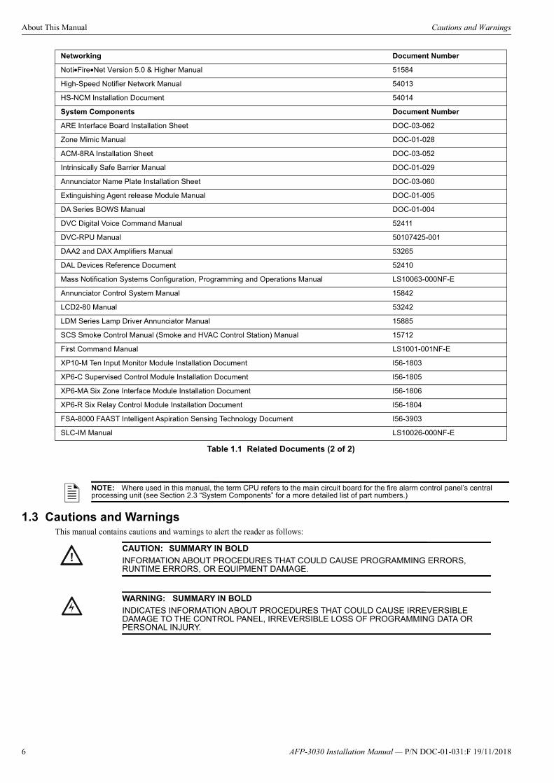
1.2 Related Documents The table below provides a list of documents referenced in this manual, as well as documents for selected other compatible devices.
Off-line Programming Utility Document Number
VeriFire Tools Programming Utilities Available for download:www.notifier.com.au
Fire Alarm Control Panel (FACP) and Main Power Supply Installation Document Number
AFP-3030 Installation, Programming, and Operations Manuals DOC-01-031DOC-01-032DOC-01-033
NPS (Notifier Power Supply) Installation Sheet DOC-03-057
Battery Connection Installation Kit DOC-03-046
Table 1.1 Related Documents (1 of 2)
AFP-3030 Installation Manual — P/N DOC-01-031:F 19/11/2018 5
About This Manual Cautions and Warnings
1.3 Cautions and WarningsThis manual contains cautions and warnings to alert the reader as follows:
Networking Document Number
Noti•Fire•Net Version 5.0 & Higher Manual 51584
High-Speed Notifier Network Manual 54013
HS-NCM Installation Document 54014
System Components Document Number
ARE Interface Board Installation Sheet DOC-03-062
Zone Mimic Manual DOC-01-028
ACM-8RA Installation Sheet DOC-03-052
Intrinsically Safe Barrier Manual DOC-01-029
Annunciator Name Plate Installation Sheet DOC-03-060
Extinguishing Agent release Module Manual DOC-01-005
DA Series BOWS Manual DOC-01-004
DVC Digital Voice Command Manual 52411
DVC-RPU Manual 50107425-001
DAA2 and DAX Amplifiers Manual 53265
DAL Devices Reference Document 52410
Mass Notification Systems Configuration, Programming and Operations Manual LS10063-000NF-E
Annunciator Control System Manual 15842
LCD2-80 Manual 53242
LDM Series Lamp Driver Annunciator Manual 15885
SCS Smoke Control Manual (Smoke and HVAC Control Station) Manual 15712
First Command Manual LS1001-001NF-E
XP10-M Ten Input Monitor Module Installation Document I56-1803
XP6-C Supervised Control Module Installation Document I56-1805
XP6-MA Six Zone Interface Module Installation Document I56-1806
XP6-R Six Relay Control Module Installation Document I56-1804
FSA-8000 FAAST Intelligent Aspiration Sensing Technology Document I56-3903
SLC-IM Manual LS10026-000NF-E
NOTE: Where used in this manual, the term CPU refers to the main circuit board for the fire alarm control panel’s central processing unit (see Section 2.3 “System Components” for a more detailed list of part numbers.)
Table 1.1 Related Documents (2 of 2)
!CAUTION: SUMMARY IN BOLD
INFORMATION ABOUT PROCEDURES THAT COULD CAUSE PROGRAMMING ERRORS, RUNTIME ERRORS, OR EQUIPMENT DAMAGE.
!WARNING: SUMMARY IN BOLD
INDICATES INFORMATION ABOUT PROCEDURES THAT COULD CAUSE IRREVERSIBLE DAMAGE TO THE CONTROL PANEL, IRREVERSIBLE LOSS OF PROGRAMMING DATA OR PERSONAL INJURY.
6 AFP-3030 Installation Manual — P/N DOC-01-031:F 19/11/2018

Section 2: System Overview
2.1 System Description
2.1.1 Standard Features• Connections to easily mount from one to ten Signalling Line Circuit (SLC) loops• Network operation• Uses Notifier’s VIEW® early warning fire detection and the FlashScan® or CLIP families of detectors and modules• Alarm, Fault, and Supervisory relays• Support for 32 annunciator addresses with either 64 or 96 points each (depending on the capability of the annunciator)• Supports Open (Style 4) and Closed (Style 6/7) SLC loops• Logic Equations• Multi-line display• Ability to activate local sounder or relay bases in alarm or pre-alarm• Supervisory duct and smoke detectors• Supports Intelligent Sensing algorithms• EIA-485 connections for wiring ACS annunciators (including LDM custom graphic annunciators), TM-4 transmitter• EIA-232 connection for printer • Autoprogram feature for faster programming of new devices• Easy connection to VeriFire® Tools programming utility• The basic system power supply charges sealed lead-acid batteries ranging in capacity from 11 to 85 amp hours, and provides up to
5 amps of power for use by the CPU. • Easy connection to auxiliary power supplies and battery chargers for custom design of very large systems.• Ground fault detection• Mass Notification System compatible1
2.1.2 OptionsRefer to Section 2.3 “System Components” for descriptions of the various optional modules.
• Rubberized keypad with a standard “QWERTY” keyboard layout, a 640-character LCD display, indicator LEDs, and switches.• Separately ordered Loop Control Modules and Loop Expander Modules provide up to ten SLC loops. • Optional equipment includes: ACS devices, ACM-8RA remote relay module to provide additional relay points, and audio/voice
components.
2.1.3 System LimitationsSystem expansion must take into consideration the following:
1. The physical limitations of the cabinet configuration.2. The electrical limitations of the system power supply.3. The capacity of the secondary power source (standby batteries).
1. Control Active LED is not supported.
AFP-3030 Installation Manual — P/N DOC-01-031:F 19/11/2018 7
System Overview Specifications
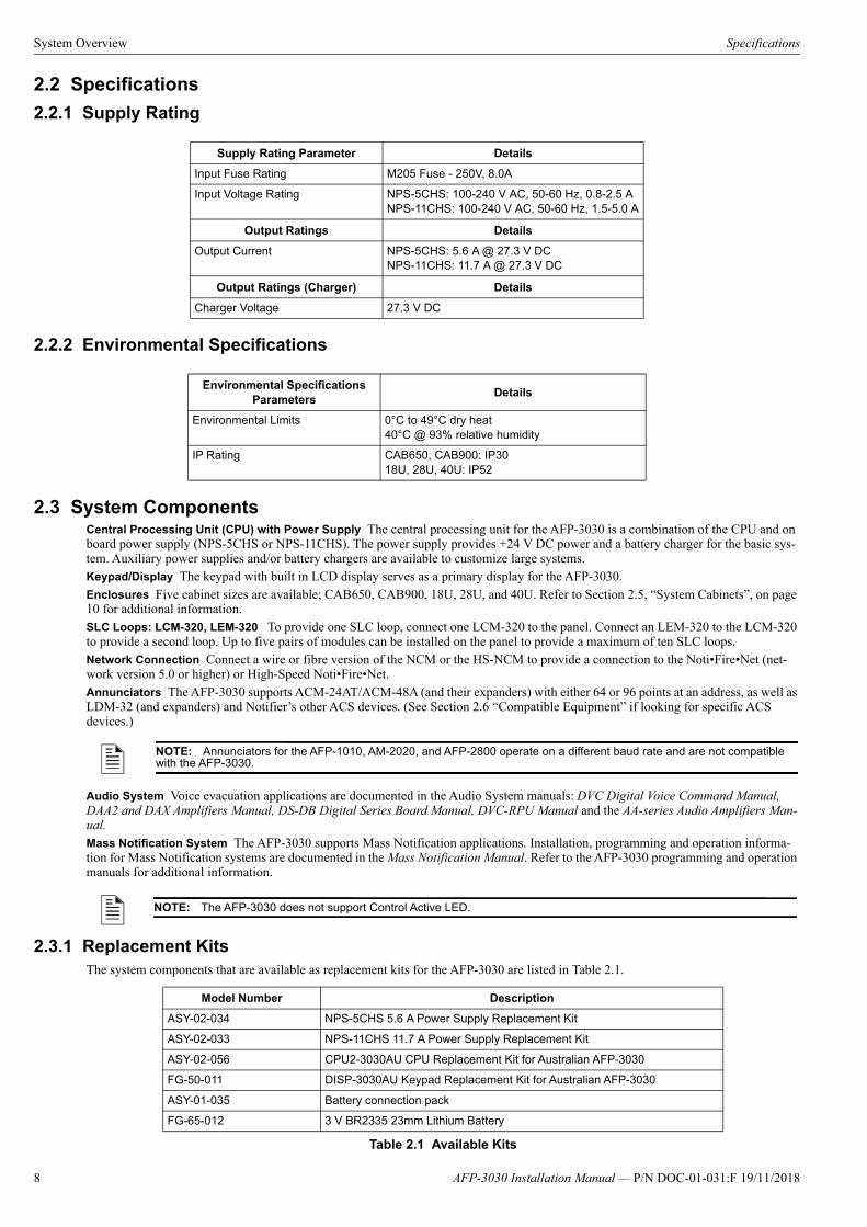
2.2 Specifications
2.2.1 Supply Rating
2.2.2 Environmental Specifications
2.3 System ComponentsCentral Processing Unit (CPU) with Power Supply The central processing unit for the AFP-3030 is a combination of the CPU and on board power supply (NPS-5CHS or NPS-11CHS). The power supply provides +24 V DC power and a battery charger for the basic sys-tem. Auxiliary power supplies and/or battery chargers are available to customize large systems.Keypad/Display The keypad with built in LCD display serves as a primary display for the AFP-3030.Enclosures Five cabinet sizes are available; CAB650, CAB900, 18U, 28U, and 40U. Refer to Section 2.5, “System Cabinets”, on page 10 for additional information.SLC Loops: LCM-320, LEM-320 To provide one SLC loop, connect one LCM-320 to the panel. Connect an LEM-320 to the LCM-320 to provide a second loop. Up to five pairs of modules can be installed on the panel to provide a maximum of ten SLC loops. Network Connection Connect a wire or fibre version of the NCM or the HS-NCM to provide a connection to the Noti•Fire•Net (net-work version 5.0 or higher) or High-Speed Noti•Fire•Net. Annunciators The AFP-3030 supports ACM-24AT/ACM-48A (and their expanders) with either 64 or 96 points at an address, as well as LDM-32 (and expanders) and Notifier’s other ACS devices. (See Section 2.6 “Compatible Equipment” if looking for specific ACS devices.)
Audio System Voice evacuation applications are documented in the Audio System manuals: DVC Digital Voice Command Manual, DAA2 and DAX Amplifiers Manual, DS-DB Digital Series Board Manual, DVC-RPU Manual and the AA-series Audio Amplifiers Man-ual.Mass Notification System The AFP-3030 supports Mass Notification applications. Installation, programming and operation informa-tion for Mass Notification systems are documented in the Mass Notification Manual. Refer to the AFP-3030 programming and operation manuals for additional information.
2.3.1 Replacement KitsThe system components that are available as replacement kits for the AFP-3030 are listed in Table 2.1.
Supply Rating Parameter Details
Input Fuse Rating M205 Fuse - 250V, 8.0A
Input Voltage Rating NPS-5CHS: 100-240 V AC, 50-60 Hz, 0.8-2.5 ANPS-11CHS: 100-240 V AC, 50-60 Hz, 1.5-5.0 A
Output Ratings Details
Output Current NPS-5CHS: 5.6 A @ 27.3 V DCNPS-11CHS: 11.7 A @ 27.3 V DC
Output Ratings (Charger) Details
Charger Voltage 27.3 V DC
Environmental Specifications Parameters
Details
Environmental Limits 0°C to 49°C dry heat40°C @ 93% relative humidity
IP Rating CAB650, CAB900: IP3018U, 28U, 40U: IP52
NOTE: Annunciators for the AFP-1010, AM-2020, and AFP-2800 operate on a different baud rate and are not compatible with the AFP-3030.
NOTE: The AFP-3030 does not support Control Active LED.
Model Number Description
ASY-02-034 NPS-5CHS 5.6 A Power Supply Replacement Kit
ASY-02-033 NPS-11CHS 11.7 A Power Supply Replacement Kit
ASY-02-056 CPU2-3030AU CPU Replacement Kit for Australian AFP-3030
FG-50-011 DISP-3030AU Keypad Replacement Kit for Australian AFP-3030
ASY-01-035 Battery connection pack
FG-65-012 3 V BR2335 23mm Lithium Battery
Table 2.1 Available Kits
8 AFP-3030 Installation Manual — P/N DOC-01-031:F 19/11/2018
Product Diagram System Overview
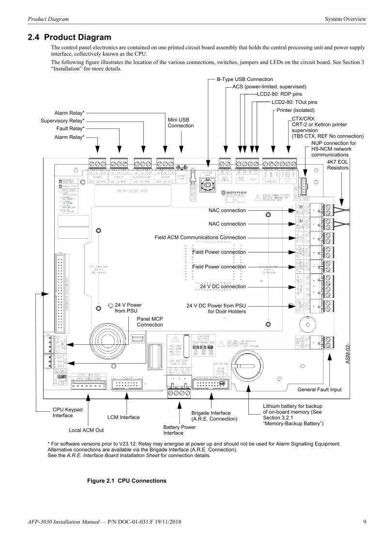
2.4 Product DiagramThe control panel electronics are contained on one printed circuit board assembly that holds the central processing unit and power supply interface, collectively known as the CPU.
The following figure illustrates the location of the various connections, switches, jumpers and LEDs on the circuit board. See Section 3 “Installation” for more details.
Figure 2.1 CPU Connections
Alarm Relay*
Fault Relay*
Supervisory Relay*
Alarm Relay*Mini USB Connection
ACS (power-limited, supervised)
Printer (isolated)
CTX/CRXCRT-2 or Keltron printer supervision(TB5 CTX, REF No connection)
Lithium battery for backup of on-board memory (See Section 3.2.1 “Memory-Backup Battery”)
CPU Keypad Interface LCM Interface
NAC connection
AS
M-0
2-
LCD2-80: TOut pins
B-Type USB Connection
Battery Power Interface
Brigade Interface (A.R.E. Connection)
LCD2-80: RDP pins
24 V DC Power from PSUfor Door Holders
NAC connection
24 V DC connection
Field ACM Communications Connection
Field Power connection
Field Power connection
Local ACM Out
General Fault Input
NUP connection for HS-NCM network communications
24 V Power from PSU
Panel MCP Connection
4K7 EOL Resistors
* For software versions prior to V23.12: Relay may energise at power up and should not be used for Alarm Signalling Equipment. Alternative connections are available via the Brigade Interface (A.R.E. Connection).See the A.R.E. Interface Board Installation Sheet for connection details.
AFP-3030 Installation Manual — P/N DOC-01-031:F 19/11/2018 9
System Overview System Cabinets
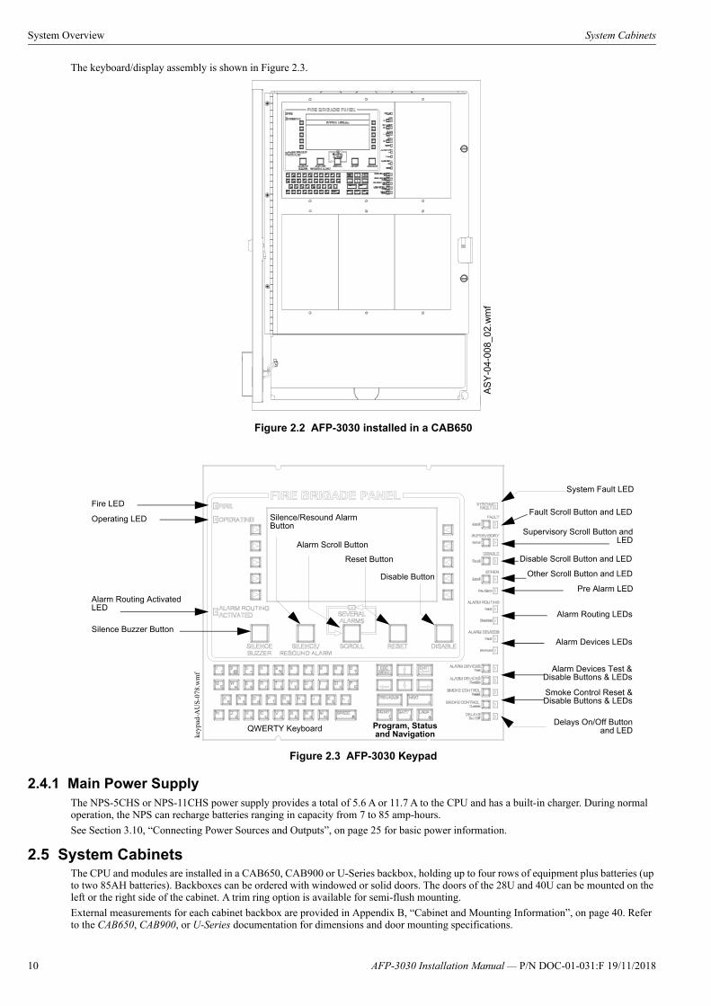
The keyboard/display assembly is shown in Figure 2.3.
Figure 2.2 AFP-3030 installed in a CAB650
Figure 2.3 AFP-3030 Keypad
2.4.1 Main Power SupplyThe NPS-5CHS or NPS-11CHS power supply provides a total of 5.6 A or 11.7 A to the CPU and has a built-in charger. During normal operation, the NPS can recharge batteries ranging in capacity from 7 to 85 amp-hours.
See Section 3.10, “Connecting Power Sources and Outputs”, on page 25 for basic power information.
2.5 System CabinetsThe CPU and modules are installed in a CAB650, CAB900 or U-Series backbox, holding up to four rows of equipment plus batteries (up to two 85AH batteries). Backboxes can be ordered with windowed or solid doors. The doors of the 28U and 40U can be mounted on the left or the right side of the cabinet. A trim ring option is available for semi-flush mounting.
External measurements for each cabinet backbox are provided in Appendix B, “Cabinet and Mounting Information”, on page 40. Refer to the CAB650, CAB900, or U-Series documentation for dimensions and door mounting specifications.
AS
Y-0
4-00
8_02
.wm
f
Silence Buzzer Button
Operating LED Silence/Resound Alarm Button
Alarm Routing Activated LED
Alarm Routing LEDs
QWERTY Keyboard
Fire LED
Alarm Scroll Button
Fault Scroll Button and LED
Reset Button
Disable Button
keyp
ad-A
US
-078
.wm
f Alarm Devices Test &Disable Buttons & LEDs
Program, Status and Navigation
Supervisory Scroll Button andLED
Other Scroll Button and LED
Smoke Control Reset &Disable Buttons & LEDs
Delays On/Off Buttonand LED
System Fault LED
Alarm Devices LEDs
Pre Alarm LED
Disable Scroll Button and LED
10 AFP-3030 Installation Manual — P/N DOC-01-031:F 19/11/2018
Compatible Equipment System Overview
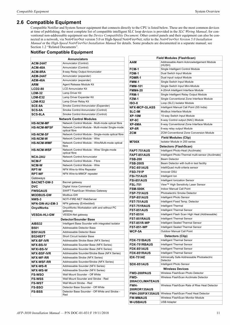
2.6 Compatible EquipmentCompatible Notifier and System Sensor equipment that connects directly to the CPU is listed below. These are the most common devices at time of publishing; the most complete list of compatible intelligent SLC loop devices is provided in the SLC Wiring Manual; for con-ventional non-addressable equipment see the Device Compatibility Document. Other control panels and their equipment can also be con-nected in a network, via Noti•Fire•Net version 5.0 or High-Speed Noti•Fire•Net; refer to the Noti•Fire•Net Version 5.0 Installation Manual or the High-Speed Noti•Fire•Net Installation Manual for details. Some products are documented in a separate manual; see Section 1.2 “Related Documents”.
Notifier Compatible Equipment
AnnunciatorsACM-24AT Annunciator (Control)
ACM-48A Annunciator (Control)
ACM-8RA 8-way Relay Output Annunciator
AEM-24AT Annunciator (expander)
AEM-48A Annunciator (expander)
ARM Agent Release Module Kit
LCD2-80 LCD Annunciator Kit
LDM-32 Lamp Driver Kit
LDM-E32 Lamp Driver Expander Kit
LDM-R32 Lamp Driver Relay Kit
SCE-8A Smoke Control Annunciator (Expander)
SCS-8A Smoke Control Annunciator (Control)
SCS-8LA Smoke Control Annunciator (Control)
Network Control ModulesHS-NCM-MF Network Control Module - Multi-mode optical fibre
HS-NCM-MFSF Network Control Module - Multi-mode/ Single-mode optical fibre
HS-NCM-SF Network Control Module - Single-mode optical fibre
HS-NCM-W Network Control Module - Wire
HS-NCM-WMF Network Control Module - Wire/Multi-mode optical fibre
HS-NCM-WSF Network Control Module - Wire/ Single-mode optical fibre
NCA-2AU Network Control Annunciator
NCM-F Network Control Module - Fibre
NCM-W Network Control Module - Wire
RPT-W NFN Wire-to-Wire Repeater
RPT-WF NFN Wire-to-MMOF repeater
GatewaysBACNET-GW-3 Bacnet gateway
DVC Digital Voice Command
FWSGAUS SWIFT FlashScan Wireless Gateway
MODBUS-GW Modbus-GW
NWS-3 NOTI-FIRE-NET WebServer
NFN-GW-AU-EM-3 NFN gateway (Embedded)
OnyxWorks OnyxWorks Workstation with and without PC gateway
VESDA-HLI-GW VESDA-Net gateway
Detector/Sounder BaseAIBS32 Intelligent Base Sounder with integrated isolator
B501 Addressable Detector Base
B501AUS Addressable Detector Base
B524IEFT Short Circuit Isolator Base
NFX-BF-IVR Addressable Strobe Base (NFX Series)
NFX-BS-IV Addressable Sounder Base (NFX Series)
NFXI-BS-IV Addressable Sounder Base (NFX Series)
NFX-BSF-IVR Addressable Sounder/Strobe Base (NFX Series)
NFX-WF-RR Addressable Strobe (NFX Series)
NFX-WSF-RR Addressable Sounder/Strobe (NFX Series)
NFX-WS-R Addressable Sounder (NFX Series)
NFX-WS-W Addressable Sounder (NFX Series)
FS-WSO Wall Mount Sounder - Off White
FS-WSS Wall Mount Sounder and Strobe - Red
FS-WST Wall Mount Strobe - Red
FS-BSO Detector Base Sounder - Off White
FS-BSS Detector Base Sounder - Off White and Strobe - Red
Field Modules (FlashScan)AAM Addressable Alarm Acknowledgement Module
(HUSH)
FCM-1 Single Intelligent Control Module
FDM-1 Dual Switch Input Module
FDMR-1 Dual input/ output Module
FMM-1 Single Switch Input Module
FMM-101 Single Switch Input Mini-Module
FMM4-20 4-20mA Intelligent Interface Module
FRM-1 Single Intelligent Relay Output Module
FZM-1 Single Conventional Zone Interface Module
ISO-X Loop (SLC) Isolator Module
NFX-MCP-GLASS Intelligent Manual Call Point (SS India)
SLC-IM Modbus Interface Module
XP-10M 10-way Switch Input Module
XP-6C 6-way Control output (NAC) Module
XP-6MA 6-way Conventional Zone Interface Module
XP-6R 6-way relay output Module
ZCM ZCM Conventional Zone Conversion Module
Field Modules (Clip)M700X Isolator Module in 200 series
Detectors (FlashScan)FAPT-751AUS Intelligent Photo-Heat (Acclimate)
FAPT-851AUS Intelligent Photo-Thermal multi-sensor (Acclimate)
FSB-200 Beam Detector
FSB-200S Beam Detector with built-in test facility
FSC-851AUS IntelliQuad multi-criteria sensor
FSD-751P Innovair DSU
FSI-751AUS Intelligent Ion
FSI-851AUS Intelligent Ionization Sensor
FSL-751 View™ High Sensitivity Laser Sensor
FSM-500K Indoor Manual Call Point
FSP-751AUS Photoelectric Smoke Detector
FSP-851AUS Intelligent Photo Sensor
FST-751AUS Intelligent Fixed Temp. Detector
FST-751RAUS Intelligent Thermal
FST-851AUS Intelligent Thermal Sensor
FST-851H Intelligent Flash Scan High Heat (Addressable)
FST-851RAUS Intelligent Thermal Sensor
FST-851R-WP Intelligent Sealed Thermal Sensor
FST-851-WP Intelligent Sealed Thermal Sensor
WCP-5A Outdoor Manual Call Point
Detectors (Clip)FDX-751BAUS Intelligent Thermal Sensor
FDX-751RBAUS Intelligent Thermal Sensor
FDX-851AUS Intelligent Thermal Sensor
FDX-851RAUS Intelligent Thermal Sensor
IDX-751AE Intrinsically Safe Addressable Photoelectric Detector
SDX-851AUS Intelligent Photo Sensor
Wireless DevicesFWD-200PAUS Wireless FlashScan Photo Detector
FWD-200ACCLIMATEAUS
Wireless FlashScan Acclimate Detector
FWH-200ROR135AUS
Wireless FlashScan Rate of Rise Heat Detector
FWH-200FIX135AUS Wireless FlashScan Fixed Heat Detector
FW-MMAUS Wireless FlashScan Monitor Module
W-USBAUS USB Adapter
AFP-3030 Installation Manual — P/N DOC-01-031:F 19/11/2018 11
Section 3: Installation
3.1 Preparing for InstallationChoose a location for the fire alarm system that is clean, dry, and vibration-free with moderate temperature. The area should be readily accessible with sufficient room to easily install and maintain it. There should be sufficient space for cabinet door(s) to open completely.
Carefully unpack the system and inspect for shipping damage. Count the number of conductors needed for all devices and find the appro-priate knockouts.
Before installing the fire alarm system, read the following:
• Review the installation precautions at the front of this manual.• Installers should be familiar with the standards and codes specified in Section 1.1 “Agency Approvals”.• All wiring must comply with the National and Local codes for fire alarm systems.• Do not draw wiring into the bottom 25 cm of the cabinet except when using a separate battery cabinet; this space is for internal
battery installation.• Review installation instructions in Section 3.2 “Installation Checklist”.
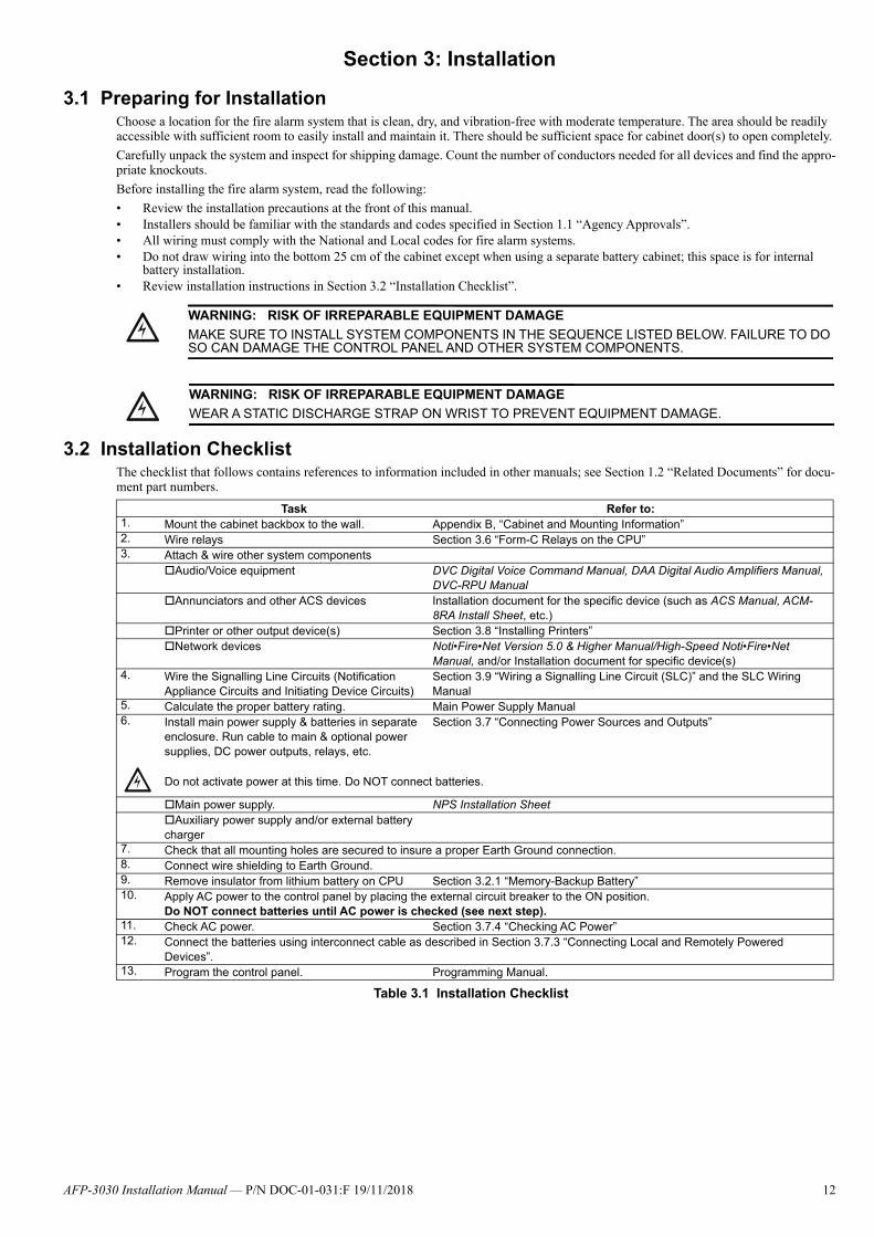
3.2 Installation ChecklistThe checklist that follows contains references to information included in other manuals; see Section 1.2 “Related Documents” for docu-ment part numbers.
!WARNING: RISK OF IRREPARABLE EQUIPMENT DAMAGE
MAKE SURE TO INSTALL SYSTEM COMPONENTS IN THE SEQUENCE LISTED BELOW. FAILURE TO DO SO CAN DAMAGE THE CONTROL PANEL AND OTHER SYSTEM COMPONENTS.
!WARNING: RISK OF IRREPARABLE EQUIPMENT DAMAGE
WEAR A STATIC DISCHARGE STRAP ON WRIST TO PREVENT EQUIPMENT DAMAGE.
Task Refer to:1. Mount the cabinet backbox to the wall. Appendix B, “Cabinet and Mounting Information”2. Wire relays Section 3.6 “Form-C Relays on the CPU”3. Attach & wire other system components
Audio/Voice equipment DVC Digital Voice Command Manual, DAA Digital Audio Amplifiers Manual, DVC-RPU Manual
Annunciators and other ACS devices Installation document for the specific device (such as ACS Manual, ACM-8RA Install Sheet, etc.)
Printer or other output device(s) Section 3.8 “Installing Printers” Network devices Noti•Fire•Net Version 5.0 & Higher Manual/High-Speed Noti•Fire•Net
Manual, and/or Installation document for specific device(s)4. Wire the Signalling Line Circuits (Notification
Appliance Circuits and Initiating Device Circuits)Section 3.9 “Wiring a Signalling Line Circuit (SLC)” and the SLC Wiring Manual
5. Calculate the proper battery rating. Main Power Supply Manual6. Install main power supply & batteries in separate
enclosure. Run cable to main & optional power supplies, DC power outputs, relays, etc.
Section 3.7 “Connecting Power Sources and Outputs”
Do not activate power at this time. Do NOT connect batteries.
Main power supply. NPS Installation SheetAuxiliary power supply and/or external battery charger
7. Check that all mounting holes are secured to insure a proper Earth Ground connection.8. Connect wire shielding to Earth Ground.9. Remove insulator from lithium battery on CPU Section 3.2.1 “Memory-Backup Battery”10. Apply AC power to the control panel by placing the external circuit breaker to the ON position.
Do NOT connect batteries until AC power is checked (see next step).11. Check AC power. Section 3.7.4 “Checking AC Power”12. Connect the batteries using interconnect cable as described in Section 3.7.3 “Connecting Local and Remotely Powered
Devices”.13. Program the control panel. Programming Manual.
Table 3.1 Installation Checklist
!
AFP-3030 Installation Manual — P/N DOC-01-031:F 19/11/2018 12

Attaching Option Boards Installation
3.2.1 Memory-Backup BatteryThe lithium battery on the CPU provides backup of the CPU’s on-board memory during power loss. The CPU ships with an insulator to prevent the battery from discharging. To preserve the battery, the insulating tube should be left in place as long as possible before applying AC power.
If the insulator is not removed before applying AC power, the control panel will show a fault situation.
This battery’s shelf-life should exceed 10 years, but if for some reason it fails, the control panel will show a fault when powered up. To replace the lithium battery:
1. Make a full backup of all system settings to prevent loss of all programming data.
2. Disconnect all power sources.3. Lift clip gently using a hardware tool or screwdriver, and remove battery
from under clip (use fingers, as screwdriver could damage components) before inserting new battery.
4. Follow system power-up procedures.5. Dispose of used battery promptly. Keep away from children. Do not disassemble and do not dispose of in fire.
3.3 Attaching Option BoardsIf installing option boards into a CAB650, CAB900, or U-Series backbox, mount & connect those boards at this time. This section con-tains general instructions for mounting an option board; see the documentation that shipped with your board for any product-specific instructions.
As described in Appendix B.6, “Laying Out Equipment in Cabinet and Chassis”, up to three option boards can be mounted in CHS-3L or four option boards can be mounted in the CHS-4L; additional modules can be mounted in other chassis.
Mounting procedures: Chassis mount1. Install two 3/4 inch (19.05 mm) stand-offs onto the chassis as shown in Figure 3.1. 2. Place the first option board over the stand-offs so that holes line up.3. If no more option boards will be mounted in that position, securely fasten all stand-offs with screws (provided with module). If
mounting a second option board, attach another layer of stand-offs and repeat steps 2-3. Note: Set the switches on an option board before mounting another layer in front of it.
4. If mounting a pair of SLC loop modules, refer to Section 3.5 “Connecting the Loop Control and Expander Modules” and to Section 3.5.3 “Installing a Multi-layer Module into the Chassis”.
!CAUTION: BATTERY REPLACEMENT
THE BATTERY USED IN THIS DEVICE MAY PRESENT A RISK OF FIRE OR CHEMICAL BURN IF MISTREATED. DO NOT RECHARGE, DISASSEMBLE, HEAT ABOVE 100°C, OR INCINERATE.A REPLACEMENT 3 V BR2335 LITHIUM BATTERY CAN BE ORDERED FROM NOTIFIER BY QUOTING THE PART NUMBER FG-65-012. USE OF ANY OTHER BATTERY MAY PRESENT A RISK OF FIRE OR EXPLOSION.
Lift clip gently while removing battery
Dotted line indicates location of insulator
AS
M-0
2-0
56-B
atte
ry.w
mf
CH
S-3
L.jp
g, C
HS
-
To mount option boards against the CHS-3L or CHS-4L
backplate, attach stand-offs to the chassis studs.
Figure 3.1 Mounting Option Boards in CHS-3L and CHS-4L
Slide tabs at bottom of option boards into the
matching slot.
AFP-3030 Installation Manual — P/N DOC-01-031:F 19/11/2018 13
Installation Connecting the Network Communications Module
5. For the top (second) layer of option boards, slide the tab at the bottom of the board into the slots on the chassis, and lay the boardback onto the top of the chassis so that the studs line up with mounting holes on the option board. Securely fasten all stand-offs withscrews provided with module.
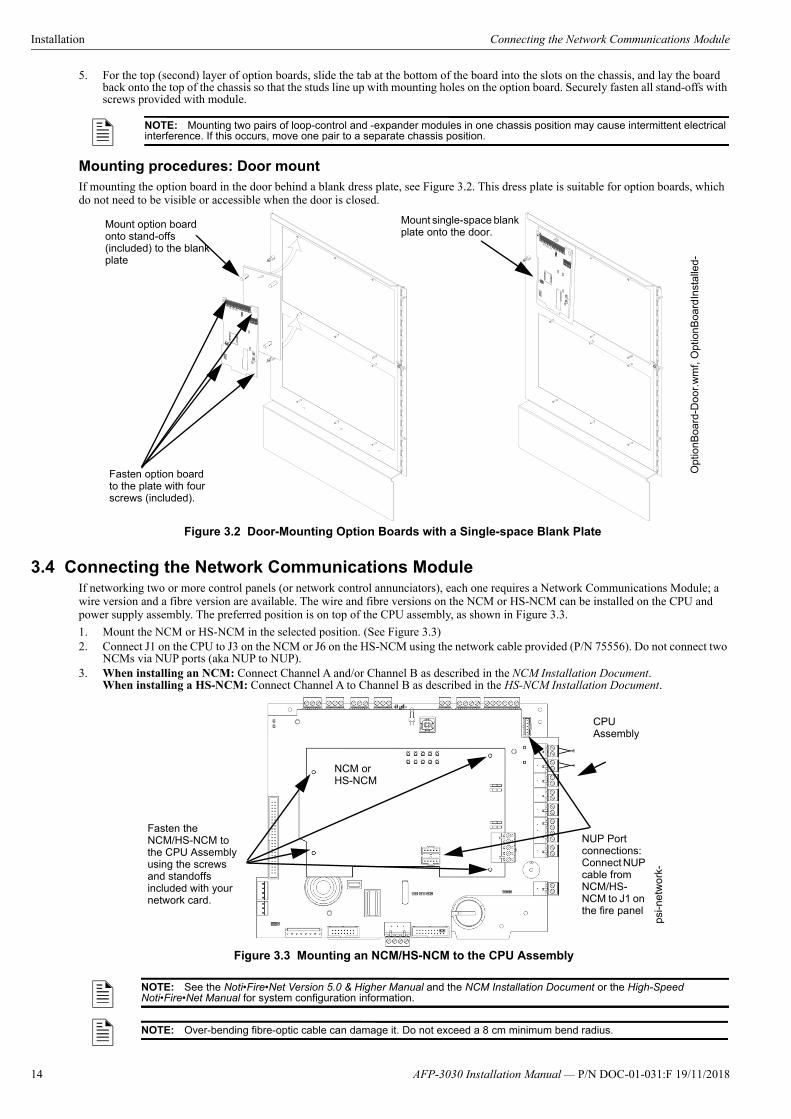
Mounting procedures: Door mountIf mounting the option board in the door behind a blank dress plate, see Figure 3.2. This dress plate is suitable for option boards, which do not need to be visible or accessible when the door is closed.
3.4 Connecting the Network Communications ModuleIf networking two or more control panels (or network control annunciators), each one requires a Network Communications Module; a wire version and a fibre version are available. The wire and fibre versions on the NCM or HS-NCM can be installed on the CPU and power supply assembly. The preferred position is on top of the CPU assembly, as shown in Figure 3.3.
1. Mount the NCM or HS-NCM in the selected position. (See Figure 3.3)2. Connect J1 on the CPU to J3 on the NCM or J6 on the HS-NCM using the network cable provided (P/N 75556). Do not connect two
NCMs via NUP ports (aka NUP to NUP).3. When installing an NCM: Connect Channel A and/or Channel B as described in the NCM Installation Document.
When installing a HS-NCM: Connect Channel A to Channel B as described in the HS-NCM Installation Document.
NOTE: Mounting two pairs of loop-control and -expander modules in one chassis position may cause intermittent electrical interference. If this occurs, move one pair to a separate chassis position.
Fasten option board to the plate with four screws (included).
Opt
ionB
oard
-Do
or.w
mf,
Opt
ionB
oard
Inst
alle
d-
Mount option board onto stand-offs (included) to the blank plate
Mount single-space blank plate onto the door.
Figure 3.2 Door-Mounting Option Boards with a Single-space Blank Plate
NOTE: See the Noti•Fire•Net Version 5.0 & Higher Manual and the NCM Installation Document or the High-Speed Noti•Fire•Net Manual for system configuration information.
NOTE: Over-bending fibre-optic cable can damage it. Do not exceed a 8 cm minimum bend radius.
Figure 3.3 Mounting an NCM/HS-NCM to the CPU Assembly
psi-n
etw
ork
-
CPU Assembly
NCM orHS-NCM
Fasten the NCM/HS-NCM to the CPU Assembly using the screws and standoffs included with your network card.
NUP Port connections: Connect NUP cable from NCM/HS-NCM to J1 on the fire panel
14 AFP-3030 Installation Manual — P/N DOC-01-031:F 19/11/2018

Connecting the Loop Control and Expander Modules Installation
3.5 Connecting the Loop Control and Expander Modules
3.5.1 Mounting InstructionsMount loop control and expander modules within the cabinet with the CPU. Typical mounting positions are in the row immediately below the fire panel. Follow the basic chassis-mounting instructions given for option boards. Loop-expander modules are mounted first; Loop-control modules are mounted on top of those. Alternately, loop-control and loop-expander modules can be attached to each other and mounted as a pair to the chassis. See Figure 3.5 for connection instructions, connector locations and stand-off lengths.
If using loop control and expander modules in CHS-4L see Figure 3.6.
After all loop-control and loop-expander modules are mounted in the cabinet, connect the SLC loops to TB1 on each loop-control and loop-expander module as shown in Figure 3.8. Daisy-chain the loop-control modules as shown in Figure 3.7. The ribbon-cable connec-tion runs from header J7 on the CPU to header J1 (“Data in”) on the first loop-control module, from J3 (“Data out”) on that unit to J1 on the next unit in the chain, and likewise for up to five loop-control modules. Each module should be assigned a unique SLC loop number (see below); loop number does not need to match the module’s location in this daisy-chain.
FlashScan devices can operate in either FlashScan or, for retrofit applications, CLIP mode. Each LCM-320 or LEM-320 running a Flash-Scan SLC can support up to 159 detectors and 159 modules. CLIP loops are limited to 99 detectors and 99 modules. These and other capacity restrictions for CLIP mode loops are discussed in Section 3.9 “Wiring a Signalling Line Circuit (SLC)”. Refer to the SLC Wir-ing Manual for wiring requirements and specific details.
3.5.2 Setting SLC Loop NumberAssign a unique SLC loop number to the loop control module by setting SW1 on the module to 1, 3, 5, 7, or 9. The loop expander mod-ule which is mounted behind this loop control module will be assigned the next-higher even number. For example, if the LCM-320 is set to loop number 5, the LEM-320 mounted to it will be set to loop number 6.
3.5.3 Installing a Multi-layer Module into the ChassisFollow the instructions illustrated in Figures 3.4 through 3.7 to install a pair of loop control/expander modules.
1. Angle the module into the chassis so that the upper end of the rear board (or boards) fits into the top slot.2. Bring the module back down so that the lower board edges slip into the bottom slots.3. Secure the module to the chassis with the two module screws. Tighten securely.4. Connect the ribbon cable to the module.
NOTE: NCM hardware is not compatible with HS-NCM hardware and should not be mixed on the same network.
NOTE: Mounting two pairs of loop control and expander modules in one chassis position may cause intermittent electrical interference. If this occurs, move one pair to a separate chassis position.
!CAUTION: DO NOT EXCEED 99 ADDRESSES FOR CLIP
DO NOT PROGRAM MORE THAN 99 ADDRESSES ON A CLIP-MODE SLC LOOP, BECAUSE THIS WILL SLOW THE SYSTEM DOWN AND COMPROMISE THE RESPONSE TIME OF THE PANEL TO DISPLAY OFF-NORMAL EVENTS.
SW1 Set to assign a unique SLC loop number
J3 Data Out to next LCM-320
J1 Data In from control panel or from previous LCM-320
Ground Fault LEDs:D32 Loop Expander Module Ground FaultD28 Loop Control Module Ground Fault
J2 LEM-320 Connection
TB1 SLC Loop Connection
LCM-320 Connection
LCM-320 LEM-320
NOTE: Note: Do not cut any jumpers on the LCM-320 or LEM-320.
TB1 SLC Loop Connection
LCM
-320
.wm
f
LEM
-320
.wm
f
Figure 3.4 LCM-320 and LEM-320 Diagram
JP2 See note.
Stand-offlocations
JP1 See note.
AFP-3030 Installation Manual — P/N DOC-01-031:F 19/11/2018 15

Installation Connecting the Loop Control and Expander Modules
NOTE: Depending on system components, clearance may be tight. Do not force modules! Move the assembly around gently until you find the angle where components and mounting studs pass each other without scraping together.
J2
SLCB+ A+ B- A- T
B1
J1
J1
Figure 3.5 Connecting Loop Control Modules with Loop Expander Modules
Loop Expander Module
LoopControlModule
J1
J2
Loop Expander Module
LoopControlModule
The long-pin end plugs directly into the back of
the Loop Control Module board.
The short-pin end plugs directly into the top of the Loop Expander Module plug.
Stand-offlocations
J2 on LCM-320“LEM-320 Data”
Loop Expander Module mounted behind Loop Control Module
LEM
-
!CAUTION:
IF THE STACKER-CONNECTOR IS INSTALLED UPSIDE-DOWN, THE SHORT-PIN END OF THE PLUG CAN FAIL TO MAKE A SECURE CONNECTION WHEN PLUGGED THROUGH THE LOOP CONTROL MODULE.
WARNING: RISK EQUIPMENT DAMAGE.
USE SPECIFIED STAND-OFF MOUNTING LOCATIONS ONLY. SEE FIGURES 3.4 AND 3.5. DO NOT USE CORNER HOLES FOR INSTALLATION PURPOSES.
Angle tab on loop control module into slot on CHS-4L
Use a slimline screwdriver (3/32”) to fasten down LEM-320 through the hole in the LCM-320 board.
CH
S-4
L-LE
M-L
CM
.cdr
Figure 3.6 Inserting Pair of Loop Control and Expander Modules into CHS-4L
For mounting in CHS-3L, see Figure 3.1
16 AFP-3030 Installation Manual — P/N DOC-01-031:F 19/11/2018
Form-C Relays on the CPU Installation
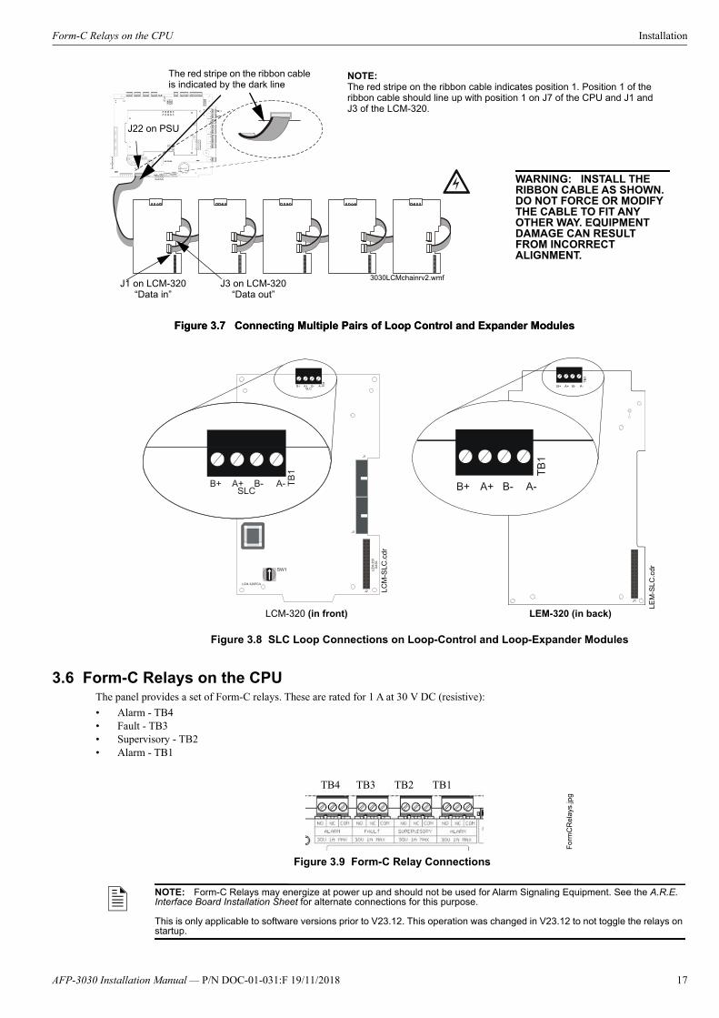
3.6 Form-C Relays on the CPUThe panel provides a set of Form-C relays. These are rated for 1 A at 30 V DC (resistive):
• Alarm - TB4• Fault - TB3• Supervisory - TB2• Alarm - TB1
Figure 3.7 Connecting Multiple Pairs of Loop Control and Expander Modules
J22 on PSU
J1 on LCM-320“Data in”
J3 on LCM-320“Data out”
3030LCMchainrv2.wmf
Figure 3.7 Connecting Multiple Pairs of Loop Control and Expander Modules
NOTE:The red stripe on the ribbon cable indicates position 1. Position 1 of the ribbon cable should line up with position 1 on J7 of the CPU and J1 and J3 of the LCM-320.
WARNING: INSTALL THE RIBBON CABLE AS SHOWN. DO NOT FORCE OR MODIFY THE CABLE TO FIT ANY OTHER WAY. EQUIPMENT DAMAGE CAN RESULT FROM INCORRECT ALIGNMENT.
!
The red stripe on the ribbon cable is indicated by the dark line
LEM
-SL
C.c
dr
LCM
-SLC
.cdr
LCM-320 (in front) LEM-320 (in back)
Figure 3.8 SLC Loop Connections on Loop-Control and Loop-Expander Modules
NOTE: Form-C Relays may energize at power up and should not be used for Alarm Signaling Equipment. See the A.R.E. Interface Board Installation Sheet for alternate connections for this purpose.
This is only applicable to software versions prior to V23.12. This operation was changed in V23.12 to not toggle the relays on startup.
For
mC
Re
lays
.jpg
Figure 3.9 Form-C Relay Connections
TB4 TB3 TB2 TB1
AFP-3030 Installation Manual — P/N DOC-01-031:F 19/11/2018 17
Installation Connecting Power Sources and Outputs
3.7 Connecting Power Sources and Outputs
3.7.1 OverviewComplete all mounting procedures and check all wiring before applying power. Electrical connections include the following:
• Primary power source. +24 V DC, delivered through the NPS main power supply. For cabinet placement information seeAppendix B.6 “Laying Out Equipment in Cabinet and Chassis” and the NPS Installation Sheet.
• Secondary power source. +24 V DC from batteries, installed in the control panel (or in an optional battery cabinet). Secondary(battery) power is required to support the system during loss of primary power.
• External power sources. +24 V DC auxiliary power supplies.• Accessory power for peripheral devices. The NPS provides +24 V DC power to devices within the same enclosure as the CPU. If
those devices have outputs, the outputs must be power-limited. Power rating is limited by the NPS primary power source, which is+24 V DC and 5.6 Amps (NPS-5CHS) or 11.7 Amps (NPS-11CHS) max.
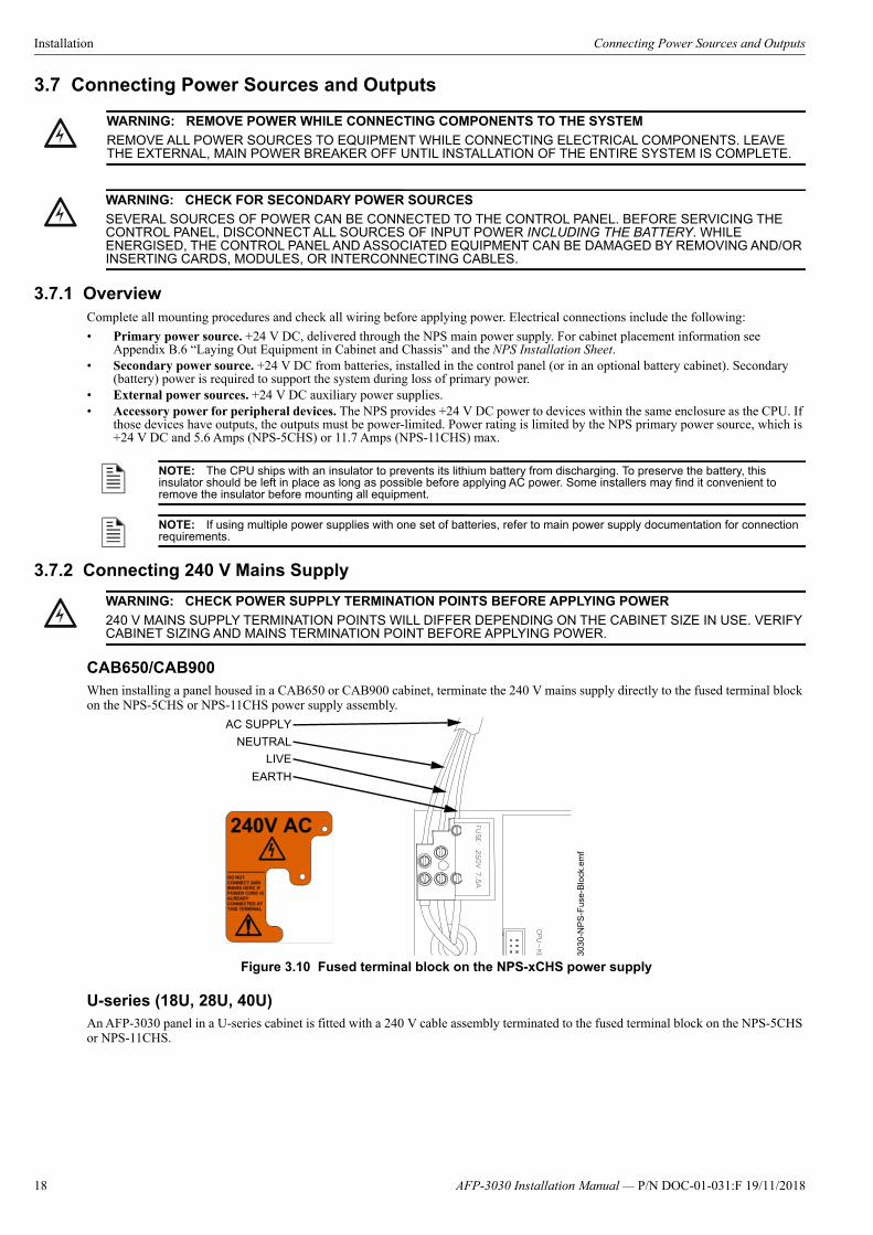
3.7.2 Connecting 240 V Mains Supply
CAB650/CAB900When installing a panel housed in a CAB650 or CAB900 cabinet, terminate the 240 V mains supply directly to the fused terminal block on the NPS-5CHS or NPS-11CHS power supply assembly.
U-series (18U, 28U, 40U)An AFP-3030 panel in a U-series cabinet is fitted with a 240 V cable assembly terminated to the fused terminal block on the NPS-5CHS or NPS-11CHS.
!WARNING: REMOVE POWER WHILE CONNECTING COMPONENTS TO THE SYSTEM
REMOVE ALL POWER SOURCES TO EQUIPMENT WHILE CONNECTING ELECTRICAL COMPONENTS. LEAVE THE EXTERNAL, MAIN POWER BREAKER OFF UNTIL INSTALLATION OF THE ENTIRE SYSTEM IS COMPLETE.
!WARNING: CHECK FOR SECONDARY POWER SOURCES
SEVERAL SOURCES OF POWER CAN BE CONNECTED TO THE CONTROL PANEL. BEFORE SERVICING THE CONTROL PANEL, DISCONNECT ALL SOURCES OF INPUT POWER INCLUDING THE BATTERY. WHILE ENERGISED, THE CONTROL PANEL AND ASSOCIATED EQUIPMENT CAN BE DAMAGED BY REMOVING AND/OR INSERTING CARDS, MODULES, OR INTERCONNECTING CABLES.
NOTE: The CPU ships with an insulator to prevents its lithium battery from discharging. To preserve the battery, this insulator should be left in place as long as possible before applying AC power. Some installers may find it convenient to remove the insulator before mounting all equipment.
NOTE: If using multiple power supplies with one set of batteries, refer to main power supply documentation for connection requirements.
!WARNING: CHECK POWER SUPPLY TERMINATION POINTS BEFORE APPLYING POWER
240 V MAINS SUPPLY TERMINATION POINTS WILL DIFFER DEPENDING ON THE CABINET SIZE IN USE. VERIFY CABINET SIZING AND MAINS TERMINATION POINT BEFORE APPLYING POWER.
Figure 3.10 Fused terminal block on the NPS-xCHS power supply
303
0-N
PS
-Fus
e-B
lock
.em
f
AC SUPPLY
NEUTRAL
LIVE
EARTH
18 AFP-3030 Installation Manual — P/N DOC-01-031:F 19/11/2018

Connecting Power Sources and Outputs Installation
Terminate 240 V mains supply to the double GPO inside the cabinet, and use this GPO to provide power to the NPS-5CHS or NPS-11CHS via the pre-terminated cable assembly.
3.7.3 Connecting Local and Remotely Powered Devices Refer to Figure 3.12 for power connections for a locally powered device. Refer to Figures 3.13 and 3.14 for power connections to a remote or secondary device from a locally powered device.
Figure 3.12 Connecting a Locally Powered CPU to power
Figure 3.11 GPO in U-series cabinets
FUSEDTERMINAL
BLOCK
240 V CABLEASSEMBLY
GPOExternal mains
terminates here inU-series cabinets
303
0-N
PS
-GP
O.e
mf
RedRed
BlackBlack
To NPS Power Supply
To Battery
BlackRed
AFP-3030 Installation Manual — P/N DOC-01-031:F 19/11/2018 19

Installation Connecting Power Sources and Outputs
Figure 3.13 Connecting a Remotely Powered CPU to the Main CPU
Main CPU(Locally Powered)
Red (+)Black (-)
Red (+)Black (-)
Remote CPU
20 AFP-3030 Installation Manual — P/N DOC-01-031:F 19/11/2018

Connecting Power Sources and Outputs Installation
Figure 3.14 Connecting a Secondary CPU to the Main CPU within the same cabinet
3.7.4 Checking AC PowerPower up the fire panel by switching on the PSU switch. The device will be on when the PSU switch is illuminated (red).
Figure 3.15 Location of the PSU Switch
Table 3.2 contains a checklist for checking the system with AC power applied to the main power supply:
NOTE: The Remote/Secondary CPU must be programmed with the Main PS Node number of the CPU from which it is drawing power. This node number must be separate from its own node number. Refer to the ‘SUPERVISION’ section of the AFP-3030 Programming Manual for more information.
Main CPU(Locally Powered)
Red (+)
Black (-)
Red (+)Black (-)
Secondary CPU
!CAUTION: CONFIRM BATTERIES ARE NOT CONNECTED
WHILE CHECKING AC POWER, MAKE SURE BATTERIES ARE NOT CONNECTED.
PSU Switch
AFP-3030 Installation Manual — P/N DOC-01-031:F 19/11/2018 21
Installation Installing Printers
3.7.5 Auxiliary Power Supply ConnectionsIf an optional auxiliary power supply is installed in the cabinet, connect it at this time. Follow the connection procedures specified by your auxiliary power supply.
3.8 Installing PrintersThis section contains information on connecting a printer to the CPU and for setting the printer options. The basic steps are as follows:
1. Make custom cable & connect it from printer to EIA-232 terminal on the CPU.2. Connect printer’s power supply.3. Configure printer settings as described in printer documentation.
Overview: PRN Printer
The PRN provides a printed record (80 columns on standard 9" x 11" tractor-feed paper) of all system events (alarm, trouble) and status changes within the system. The control panel can be configured to time-stamp the printout with the current time-of-day and date for each event. The printer can be located up to 15 metres from the control panel. Installation and configuration instructions follow.
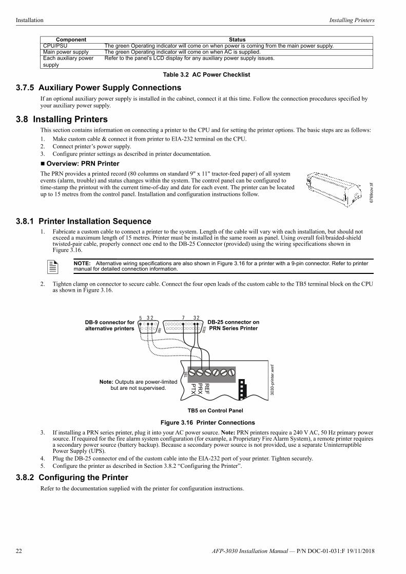
3.8.1 Printer Installation Sequence1. Fabricate a custom cable to connect a printer to the system. Length of the cable will vary with each installation, but should not
exceed a maximum length of 15 metres. Printer must be installed in the same room as panel. Using overall foil/braided-shieldtwisted-pair cable, properly connect one end to the DB-25 Connector (provided) using the wiring specifications shown inFigure 3.16.
2. Tighten clamp on connector to secure cable. Connect the four open leads of the custom cable to the TB5 terminal block on the CPUas shown in Figure 3.16.
3. If installing a PRN series printer, plug it into your AC power source. Note: PRN printers require a 240 V AC, 50 Hz primary powersource. If required for the fire alarm system configuration (for example, a Proprietary Fire Alarm System), a remote printer requiresa secondary power source (battery backup). Because a secondary power source is not provided, use a separate UninterruptiblePower Supply (UPS).
4. Plug the DB-25 connector end of the custom cable into the EIA-232 port of your printer. Tighten securely.5. Configure the printer as described in Section 3.8.2 “Configuring the Printer”.
3.8.2 Configuring the PrinterRefer to the documentation supplied with the printer for configuration instructions.
Component StatusCPU/PSU The green Operating indicator will come on when power is coming from the main power supply.Main power supply The green Operating indicator will come on when AC is supplied.Each auxiliary power supply
Refer to the panel’s LCD display for any auxiliary power supply issues.
Table 3.2 AC Power Checklist
6769
cov.
tif
NOTE: Alternative wiring specifications are also shown in Figure 3.16 for a printer with a 9-pin connector. Refer to printer manual for detailed connection information.
Note: Outputs are power-limited but are not supervised.
DB-25 connector on PRN Series Printer
TB5 on Control Panel
Figure 3.16 Printer Connections
RE
FP
RX
PT
X
303
0-p
rinte
r.w
mf
DB-9 connector for alternative printers
22 AFP-3030 Installation Manual — P/N DOC-01-031:F 19/11/2018

Wiring a Signalling Line Circuit (SLC) Installation
PRN Printer SettingsSet the printer options (under the menu area) according to the settings listed in Table 3.3.
3.9 Wiring a Signalling Line Circuit (SLC)
3.9.1 SLC OverviewCommunication between the CPU and intelligent and addressable initiating, monitor, and control devices takes place through a Signal-ling Line Circuit (SLC). This manual provides requirements and performance details specific to this control panel; for installation infor-mation and general information, refer to the SLC Wiring Manual.
For electrical specifications, see Appendix A.2 “SLC Loops”. For additional notes on SLC resistance values, see Section 4.1 “Opera-tional Checks”.
3.9.2 SLC CapacityThe AFP-3030 supports up to five pairs of LCM-320 and LEM-320 modules, providing from one to ten SLC loops. Loop capacity depends on operating mode:
• Flash Scan: 01-159 intelligent detectors, 01-159 monitor and control modules• CLIP: 01-99 intelligent detectors, 01-99 monitor and control modulesFlashScan devices can operate in either FlashScan or CLIP mode. Older models of CLIP devices only support addresses up to address99. CLIP loops are limited to 99 detectors and 99 modules.
The following configuration guidelines may be used to improve the response times of CLIP loops:
1. All manual pull stations must be assigned addresses from 1-20.2. Loops must be programmed for Rapid Poll (refer to the programming manual for specific instructions).3. Modules on a fully loaded loop must adhere to a ratio of two monitor modules to one control module.
*Protocol: When printing in graphics mode, set I/OSerial Protocol to “Robust XON/OFF”.
Option SettingL/R Adjust 0Font HS DraftCPI 10 CPILPI 6 LPISkip 0.0ESC Character ESCEmulate FX-850Bidirectional Copy ONI/O Interface Buffer Serial Baud Format Protocol *
Serial40K
96008 Bit, None, 1 StopENQ/STX
CG-TAB GraphicCharacter Set StandardCountry E-USA ASCIISelect Zero ONAuto-CR OFFAuto-LF OFF
Option SettingMenu Lock ONLanguage English
Paper Single Form Adjust Trac 1 Form Adjust Trac 2 Form Adjust Auto Sheet Feeder Form Adjust
12/72
12/72
12/72
12/72Auto Tear OFFF-Eject OFFForm Length Trac 1 Lines Standard Trac 2 Lines Standard
6610.5”
6610.5”
Barcode OffBarmode Unsecured
Option Setting
Table 3.3 PRN Setup Options
NOTE: Response times for CLIP loops may vary. CLIP loops must be tested to assure that actuation of notification appliances occurs within 10 seconds after activation of an initiating device.
AFP-3030 Installation Manual — P/N DOC-01-031:F 19/11/2018 23
Installation Connecting a FAAST Intelligent Aspiration Detector
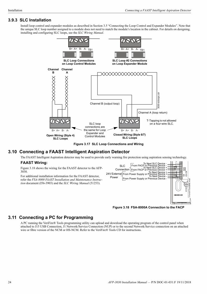
3.9.3 SLC InstallationInstall loop control and expander modules as described in Section 3.5 “Connecting the Loop Control and Expander Modules”. Note that the unique SLC loop number assigned to a module does not need to match the module’s location in the cabinet. For details on designing, installing and configuring SLC loops, see the SLC Wiring Manual.
3.10 Connecting a FAAST Intelligent Aspiration DetectorThe FAAST Intelligent Aspiration detector may be used to provide early warning fire protection using aspiration sensing technology.
FAAST Wiring:Figure 3.18 shows the wiring for the FAAST detector to the AFP-3030.
For additional installation information for the FAAST detector, refer the FSA-8000 FAAST Installation and Maintenance Instruc-tion document (I56-3903) and the SLC Wiring Manual (51253).
3.11 Connecting a PC for ProgrammingA PC running the VeriFire® Tools programming utility can upload and download the operating program of the control panel when attached to J15 USB Connection, J1 Network/Service Connection (NUP) or to the second Network/Service connection on an attached wire or fibre version of the NCM or HS-NCM. Refer to the VeriFire® Tools CD for instructions.
B+ A+ B- A- B+ A+ B- A-
TB1 B+ A+ B- A- TB1B+ A+ B- A-
T-Tapping is not allowed on a four-wire SLC.
Channel B (output loop)
Channel A (loop return)
Open Wiring (Style 4) SLC Loops
Closed Wiring (Style 6/7) SLC Loops
SLC Loop #2 Connectionson Loop Expander Module
SLC Loop Connections on Loop Control Modules
SLC loop connections are
the same for Loop Expander and
Control Modules
Channel B
Channel A
3030
-slc
loop
s.cd
r
Figure 3.17 SLC Loop Connections and Wiring
FAA
ST
Term
Blk
.wm
f
To Next SLC Device +From FACP or Previous Device +
To Next SLC Device -From FACP or Previous Device -
Figure 3.18 FSA-8000A Connection to the FACP
To Next Device +From Power Supply or Previous Device +
To Next Device -
SLC Connection
24V External Power From Power Supply or Previous Device -
24 AFP-3030 Installation Manual — P/N DOC-01-031:F 19/11/2018

Section 4: Testing the System
4.1 Operational ChecksBetween formal periodic testing and servicing intervals, the following operation checks should be performed monthly.
• Check that the green OPERATING LED lights.• Check that all status LEDs are off.• Press and hold the LAMP TEST key. Verify that all LEDs and all LCD display segments work.• Before proceeding: a) notify the fire department and the central alarm receiving station if transmitting alarm conditions; b) notify
facility personnel of the test so that alarm sounding devices are disregarded during the test period; and c) when necessary, disableactivation of alarm notification appliances and speakers to prevent their sounding.
• Activate an Initiating Device Circuit using an alarm initiating device or an addressable initiating device on the SLC and check thatall programmed active notification appliances function. Reset the alarm initiating device, the control panel, and any other associatedequipment. In voice alarm applications, confirm that the proper tone(s) and/or messages sound during alarm conditions. Select thepaging function and confirm that the message can be heard in the affected fire zones. Repeat the above step with each InitiatingDevice Circuit and each addressable device.
• Zero Ohms to ground will cause a ground fault.• On systems equipped with a firefighter’s telephone circuit, make a call from a telephone circuit and confirm a ring indication.
Answer the call and confirm communication with the incoming caller. End the call and repeat for each telephone circuit in thesystem.
• Remove AC power, activate an Initiating Device Circuit through an alarm initiating device or an addressable initiating device onthe SLC, and check that programmed active notification appliances sound, and alarm indicators illuminate. Measure the batteryvoltage with notification appliances active. Replace any battery with a terminal voltage less than 21.6 V DC and reapply AC Power.
• Return all circuits to their pretest condition.• Check that all status LEDs are off and the green POWER LED is on.• Notify fire, central station and/or building personnel when you finish testing the system.
4.2 Battery Checks and Maintenance
Maintenance-free sealed lead-acid batteries used in the system do not require the addition of water or electrolyte. These batteries are charged and maintained in a fully charged state by the main power supply's float charger during normal system operation. A discharged battery typically reaches the float voltage of 27.3 V DC within 24 hours.
Follow the manufacturer recommendations for battery replacement intervals. Minimal replacement battery capacity appears on the con-trol panel marking label. Immediately replace a leaking or damaged battery. You can get replacement batteries from the manufacturer.
• If a battery leaks and contact is made with the Sulfuric Acid, immediately flush skin and/or eyes with water for at least 15 minutes.Water and household baking soda provides a good neutralizing solution for Sulfuric Acid.
continued…
NOTE: SLC Resistance Values: The total DC resistance of the SLC pair cannot exceed 50 ohms.For instructions on how to measure the total DC resistance of a populated SLC pair, refer to the “Measuring Loop Resistance” section of the SLC Wiring Manual (P/N 51253). The minimum DC resistance between conductors of an unpopulated SLC pair cannot be less than 1 K ohms. Measure DC resistance on an unpopulated loop as shown in Figure 4.1 on page 25.
NOTE: The battery test requires fully charged batteries. If batteries are new or discharged due to a recent power outage, allow the batteries to charge for 24 hours before testing.
SL
C-m
ea
s5.c
dr
SLC Out
SLC Return
SLC Return
SLC Out
STEP 2 STEP 3
Step 1. Disconnect the SLC channel B (Out) and SLC channel A (Return) at the control panel.Step 2. Measure and record the resistance at SLC Out.Step 3. Measure and record the resistance at SLC Return.
The minimum resistance is the lesser of two and three.
Figure 4.1 Measuring DC Resistance on an Unpopulated SLC Loop
!CAUTION:
THE MAXIMUM CURRENT RATING OF THE BATTERIES IS 11.6A. THE BATTERY CONNECTION IS FUSED. IF THE FUSE NEEDS TO BE REPLACED, IT MUST BE REPLACED WITH A 20A BLADE FUSE.
!WARNING: BATTERIES CONTAIN SULFURIC ACID,
WHICH CAN CAUSE SEVERE BURNS TO THE SKIN AND EYES AND DAMAGE TO FABRICS.
25AFP-3030 Installation Manual — P/N DOC-01-031:F 19/11/2018
Testing the System Battery Checks and Maintenance
• If Sulfuric Acid gets into eyes, seek immediate medical attention.• Ensure proper handling of the battery to prevent short circuits.• Take care to avoid accidental shorting of the leads from uninsulated work benches, tools, bracelets, rings, and coins.
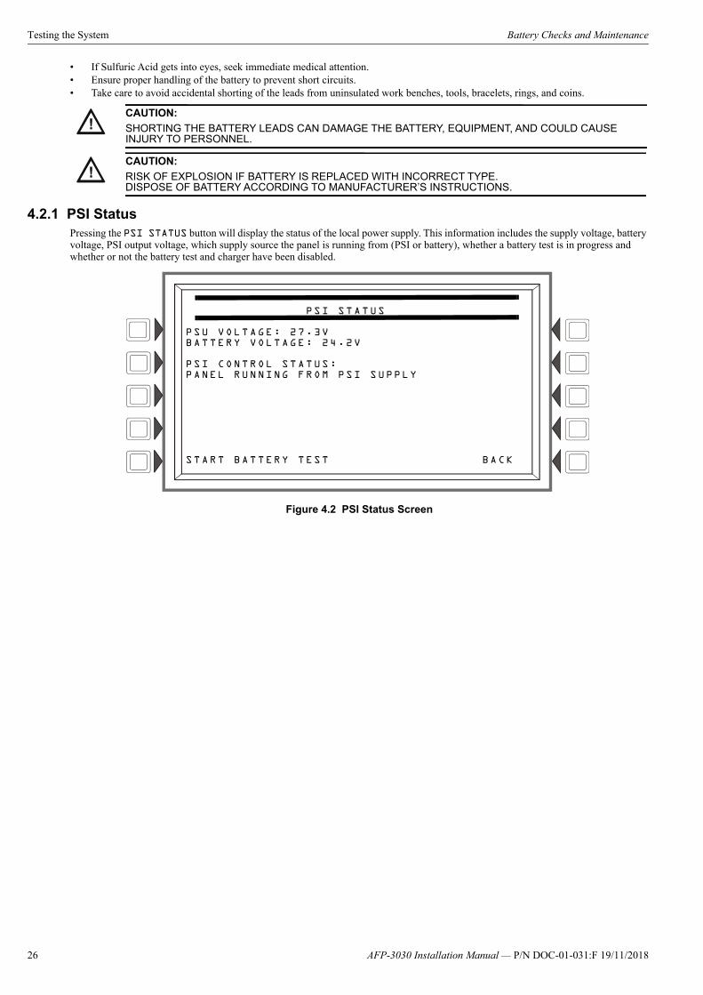
4.2.1 PSI StatusPressing the PSI STATUS button will display the status of the local power supply. This information includes the supply voltage, battery voltage, PSI output voltage, which supply source the panel is running from (PSI or battery), whether a battery test is in progress and whether or not the battery test and charger have been disabled.
Figure 4.2 PSI Status Screen
!CAUTION:
SHORTING THE BATTERY LEADS CAN DAMAGE THE BATTERY, EQUIPMENT, AND COULD CAUSE INJURY TO PERSONNEL.
!CAUTION:
RISK OF EXPLOSION IF BATTERY IS REPLACED WITH INCORRECT TYPE.DISPOSE OF BATTERY ACCORDING TO MANUFACTURER’S INSTRUCTIONS.
PSI STATUS
PSU VOLTAGE: 27.3VBATTERY VOLTAGE: 24.2V
PSI CONTROL STATUS:PANEL RUNNING FROM PSI SUPPLY
START BATTERY TEST BACK
26 AFP-3030 Installation Manual — P/N DOC-01-031:F 19/11/2018
Appendix A: Electrical Specifications
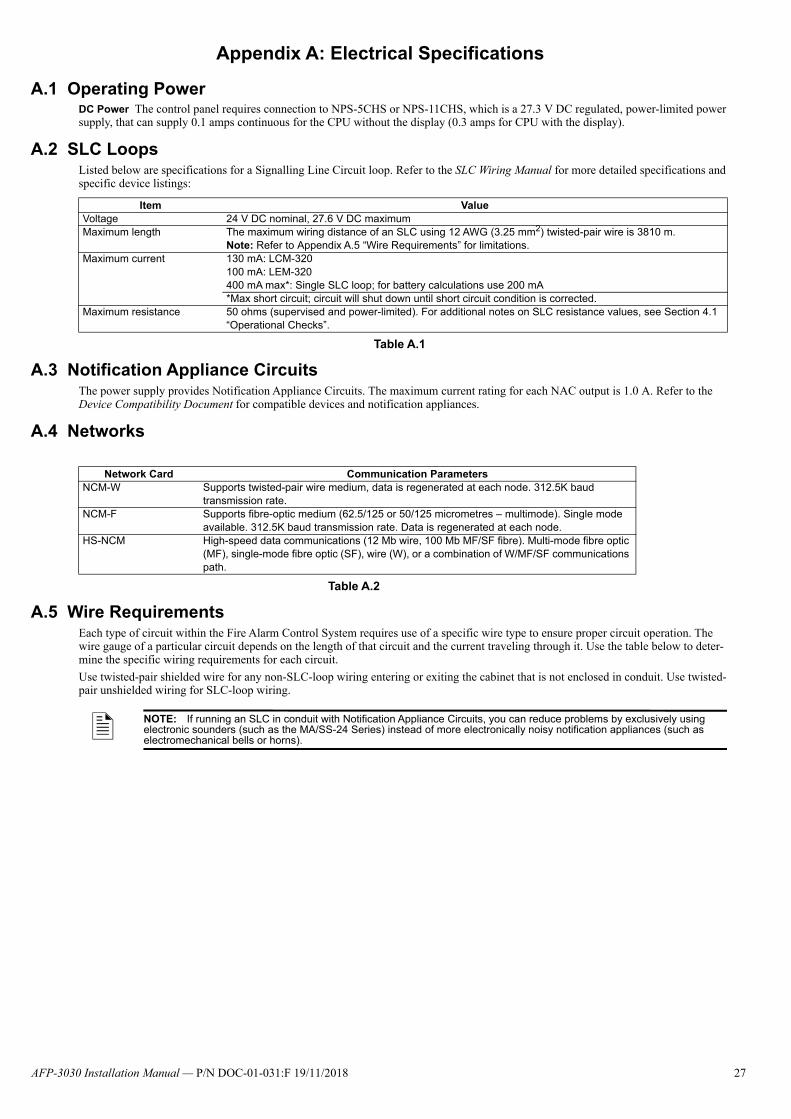
A.1 Operating PowerDC Power The control panel requires connection to NPS-5CHS or NPS-11CHS, which is a 27.3 V DC regulated, power-limited power supply, that can supply 0.1 amps continuous for the CPU without the display (0.3 amps for CPU with the display).
A.2 SLC LoopsListed below are specifications for a Signalling Line Circuit loop. Refer to the SLC Wiring Manual for more detailed specifications and specific device listings:
A.3 Notification Appliance CircuitsThe power supply provides Notification Appliance Circuits. The maximum current rating for each NAC output is 1.0 A. Refer to the Device Compatibility Document for compatible devices and notification appliances.
A.4 Networks
A.5 Wire RequirementsEach type of circuit within the Fire Alarm Control System requires use of a specific wire type to ensure proper circuit operation. The wire gauge of a particular circuit depends on the length of that circuit and the current traveling through it. Use the table below to deter-mine the specific wiring requirements for each circuit.
Use twisted-pair shielded wire for any non-SLC-loop wiring entering or exiting the cabinet that is not enclosed in conduit. Use twisted-pair unshielded wiring for SLC-loop wiring.
Item ValueVoltage 24 V DC nominal, 27.6 V DC maximumMaximum length The maximum wiring distance of an SLC using 12 AWG (3.25 mm2) twisted-pair wire is 3810 m.
Note: Refer to Appendix A.5 “Wire Requirements” for limitations.Maximum current 130 mA: LCM-320
100 mA: LEM-320 400 mA max*: Single SLC loop; for battery calculations use 200 mA*Max short circuit; circuit will shut down until short circuit condition is corrected.
Maximum resistance 50 ohms (supervised and power-limited). For additional notes on SLC resistance values, see Section 4.1 “Operational Checks”.
Table A.1
Network Card Communication ParametersNCM-W Supports twisted-pair wire medium, data is regenerated at each node. 312.5K baud
transmission rate.NCM-F Supports fibre-optic medium (62.5/125 or 50/125 micrometres – multimode). Single mode
available. 312.5K baud transmission rate. Data is regenerated at each node.HS-NCM High-speed data communications (12 Mb wire, 100 Mb MF/SF fibre). Multi-mode fibre optic
(MF), single-mode fibre optic (SF), wire (W), or a combination of W/MF/SF communications path.
Table A.2
NOTE: If running an SLC in conduit with Notification Appliance Circuits, you can reduce problems by exclusively using electronic sounders (such as the MA/SS-24 Series) instead of more electronically noisy notification appliances (such as electromechanical bells or horns).
27AFP-3030 Installation Manual — P/N DOC-01-031:F 19/11/2018
Electrical Specifications Power Supply Calculations
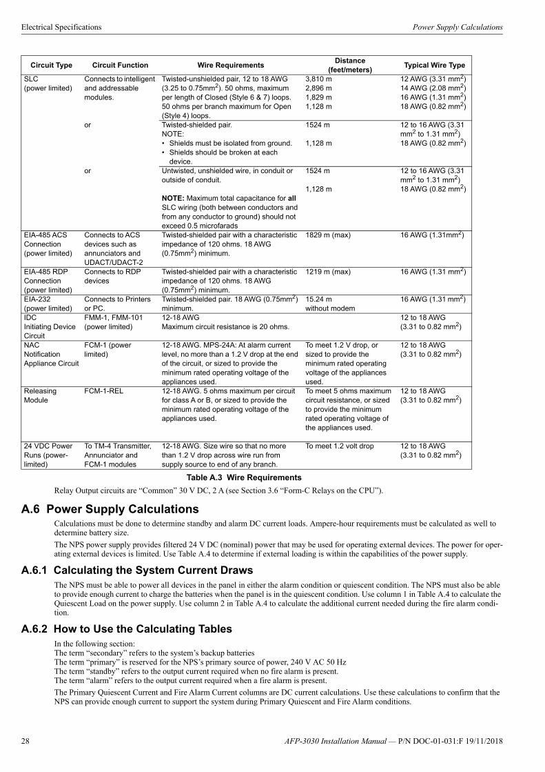
Relay Output circuits are “Common” 30 V DC, 2 A (see Section 3.6 “Form-C Relays on the CPU”).
A.6 Power Supply CalculationsCalculations must be done to determine standby and alarm DC current loads. Ampere-hour requirements must be calculated as well to determine battery size.
The NPS power supply provides filtered 24 V DC (nominal) power that may be used for operating external devices. The power for oper-ating external devices is limited. Use Table A.4 to determine if external loading is within the capabilities of the power supply.
A.6.1 Calculating the System Current DrawsThe NPS must be able to power all devices in the panel in either the alarm condition or quiescent condition. The NPS must also be able to provide enough current to charge the batteries when the panel is in the quiescent condition. Use column 1 in Table A.4 to calculate the Quiescent Load on the power supply. Use column 2 in Table A.4 to calculate the additional current needed during the fire alarm condi-tion.
A.6.2 How to Use the Calculating TablesIn the following section:The term “secondary” refers to the system’s backup batteriesThe term “primary” is reserved for the NPS’s primary source of power, 240 V AC 50 HzThe term “standby” refers to the output current required when no fire alarm is present.The term “alarm” refers to the output current required when a fire alarm is present.
The Primary Quiescent Current and Fire Alarm Current columns are DC current calculations. Use these calculations to confirm that the NPS can provide enough current to support the system during Primary Quiescent and Fire Alarm conditions.
Circuit Type Circuit Function Wire RequirementsDistance
(feet/meters) Typical Wire Type
SLC(power limited)
Connects to intelligent and addressable modules.
Twisted-unshielded pair, 12 to 18 AWG (3.25 to 0.75mm2). 50 ohms, maximum per length of Closed (Style 6 & 7) loops. 50 ohms per branch maximum for Open (Style 4) loops.
3,810 m2,896 m1,829 m1,128 m
12 AWG (3.31 mm2)14 AWG (2.08 mm2)16 AWG (1.31 mm2)18 AWG (0.82 mm2)
or Twisted-shielded pair.NOTE:• Shields must be isolated from ground.• Shields should be broken at each
device.
1524 m
1,128 m
12 to 16 AWG (3.31 mm2 to 1.31 mm2)18 AWG (0.82 mm2)
or Untwisted, unshielded wire, in conduit or outside of conduit.
NOTE: Maximum total capacitance for all SLC wiring (both between conductors and from any conductor to ground) should not exceed 0.5 microfarads
1524 m
1,128 m
12 to 16 AWG (3.31 mm2 to 1.31 mm2)18 AWG (0.82 mm2)
EIA-485 ACS Connection(power limited)
Connects to ACS devices such as annunciators and UDACT/UDACT-2
Twisted-shielded pair with a characteristic impedance of 120 ohms. 18 AWG (0.75mm2) minimum.
1829 m (max) 16 AWG (1.31mm2)
EIA-485 RDP Connection(power limited)
Connects to RDP devices
Twisted-shielded pair with a characteristic impedance of 120 ohms. 18 AWG (0.75mm2) minimum.
1219 m (max) 16 AWG (1.31 mm2)
EIA-232(power limited)
Connects to Printers or PC.
Twisted-shielded pair. 18 AWG (0.75mm2) minimum.
15.24 mwithout modem
16 AWG (1.31 mm2)
IDCInitiating Device Circuit
FMM-1, FMM-101 (power limited)
12-18 AWG Maximum circuit resistance is 20 ohms.
12 to 18 AWG (3.31 to 0.82 mm2)
NACNotification Appliance Circuit
FCM-1 (power limited)
12-18 AWG. MPS-24A: At alarm currentlevel, no more than a 1.2 V drop at the end of the circuit, or sized to provide theminimum rated operating voltage of theappliances used.
To meet 1.2 V drop, or sized to provide the minimum rated operating voltage of the appliances used.
12 to 18 AWG (3.31 to 0.82 mm2)
Releasing Module
FCM-1-REL 12-18 AWG. 5 ohms maximum per circuitfor class A or B, or sized to provide theminimum rated operating voltage of theappliances used.
To meet 5 ohms maximum circuit resistance, or sized to provide the minimum rated operating voltage of the appliances used.
12 to 18 AWG (3.31 to 0.82 mm2)
24 VDC Power Runs (power-limited)
To TM-4 Transmitter, Annunciator and FCM-1 modules
12-18 AWG. Size wire so that no morethan 1.2 V drop across wire run fromsupply source to end of any branch.
To meet 1.2 volt drop 12 to 18 AWG (3.31 to 0.82 mm2)
Table A.3 Wire Requirements
28 AFP-3030 Installation Manual — P/N DOC-01-031:F 19/11/2018

Power Supply Calculations Electrical Specifications
Quantities List the number of devices powered by the MAIN 24 V Main Output on the NPS and any auxiliary 24 V Outputs. Use these quantities to calculate total current draw of each set of devices in calculation columns 1, 2, and 3.Calculation Column 1 (Primary, Quiescent Current in amps) Add the contents of Column 1 to get the current drawn from the NPS during a quiescent condition, with AC power applied.Calculation Column 2 (Primary, Fire Alarm Current in amps) Column 2 lets the system designer determine the current load that the NPS must support during a fire alarm.
Typically, a system should contain capacity to activate all output circuits and relays, and support fire alarms on no less than 10% of Initi-ating Device Circuits.
If the system provides power for Notification Appliance Circuits, refer to the Device Compatibility Document for 24 V DC notification appliances.
NOTE: A current calculation tool can also be found in the Download Centre on the Notifier website: http://www.notifier.com.au/
AFP-3030 Installation Manual — P/N DOC-01-031:F 19/11/2018 29
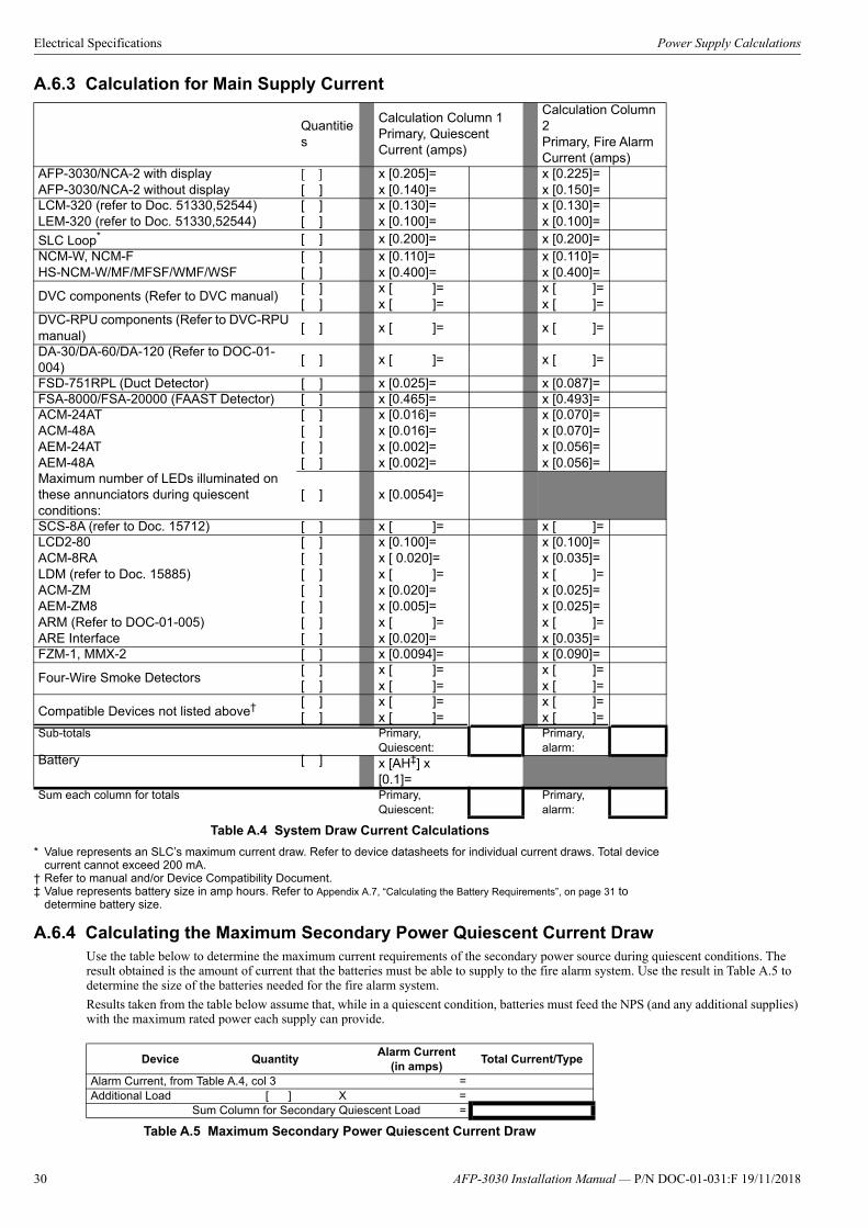
Electrical Specifications Power Supply Calculations
A.6.3 Calculation for Main Supply Current
A.6.4 Calculating the Maximum Secondary Power Quiescent Current DrawUse the table below to determine the maximum current requirements of the secondary power source during quiescent conditions. The result obtained is the amount of current that the batteries must be able to supply to the fire alarm system. Use the result in Table A.5 to determine the size of the batteries needed for the fire alarm system.
Results taken from the table below assume that, while in a quiescent condition, batteries must feed the NPS (and any additional supplies) with the maximum rated power each supply can provide.
Quantities
Calculation Column 1Primary, QuiescentCurrent (amps)
Calculation Column2Primary, Fire Alarm Current (amps)
AFP-3030/NCA-2 with displayAFP-3030/NCA-2 without display
[ ][ ]
x [0.205]=x [0.140]=
x [0.225]=x [0.150]=
LCM-320 (refer to Doc. 51330,52544)LEM-320 (refer to Doc. 51330,52544)
[ ][ ]
x [0.130]=x [0.100]=
x [0.130]=x [0.100]=
SLC Loop*
* Value represents an SLC’s maximum current draw. Refer to device datasheets for individual current draws. Total devicecurrent cannot exceed 200 mA.
[ ] x [0.200]= x [0.200]=NCM-W, NCM-FHS-NCM-W/MF/MFSF/WMF/WSF
[ ][ ]
x [0.110]=x [0.400]=
x [0.110]=x [0.400]=
DVC components (Refer to DVC manual)[ ][ ]
x [ ]=x [ ]=
x [ ]=x [ ]=
DVC-RPU components (Refer to DVC-RPU manual)
[ ] x [ ]= x [ ]=
DA-30/DA-60/DA-120 (Refer to DOC-01-004)
[ ] x [ ]= x [ ]=
FSD-751RPL (Duct Detector) [ ] x [0.025]= x [0.087]=FSA-8000/FSA-20000 (FAAST Detector) [ ] x [0.465]= x [0.493]=ACM-24ATACM-48AAEM-24ATAEM-48A
[ ][ ][ ][ ]
x [0.016]=x [0.016]=x [0.002]=x [0.002]=
x [0.070]=x [0.070]=x [0.056]=x [0.056]=
Maximum number of LEDs illuminated on these annunciators during quiescent conditions:
[ ] x [0.0054]=
SCS-8A (refer to Doc. 15712) [ ] x [ ]= x [ ]=LCD2-80ACM-8RALDM (refer to Doc. 15885)ACM-ZMAEM-ZM8ARM (Refer to DOC-01-005)ARE Interface
[ ][ ][ ][ ][ ][ ][ ]
x [0.100]=x [ 0.020]=x [ ]=x [0.020]=x [0.005]=x [ ]=x [0.020]=
x [0.100]=x [0.035]=x [ ]=x [0.025]=x [0.025]=x [ ]=x [0.035]=
FZM-1, MMX-2 [ ] x [0.0094]= x [0.090]=
Four-Wire Smoke Detectors [ ][ ]
x [ ]=x [ ]=
x [ ]=x [ ]=
Compatible Devices not listed above†
† Refer to manual and/or Device Compatibility Document.
[ ][ ]
x [ ]=x [ ]=
x [ ]=x [ ]=
Sub-totals Primary, Quiescent:
Primary, alarm:
Battery [ ] x [AH‡] x [0.1]=
‡ Value represents battery size in amp hours. Refer to Appendix A.7, “Calculating the Battery Requirements”, on page 31 to determine battery size.
Sum each column for totals Primary, Quiescent:
Primary, alarm:
Table A.4 System Draw Current Calculations
Device QuantityAlarm Current
(in amps)Total Current/Type
Alarm Current, from Table A.4, col 3 =Additional Load [ ] X =
Sum Column for Secondary Quiescent Load =
Table A.5 Maximum Secondary Power Quiescent Current Draw
30 AFP-3030 Installation Manual — P/N DOC-01-031:F 19/11/2018
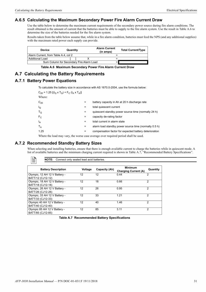
Calculating the Battery Requirements Electrical Specifications
A.6.5 Calculating the Maximum Secondary Power Fire Alarm Current DrawUse the table below to determine the maximum current requirements of the secondary power source during fire alarm conditions. The result obtained is the amount of current that the batteries must be able to supply to the fire alarm system. Use the result in Table A.6 to determine the size of the batteries needed for the fire alarm system.
Results taken from the table below assume that, while in a fire alarm condition, batteries must feed the NPS (and any additional supplies) with the maximum rated power each supply can provide.
A.7 Calculating the Battery Requirements
A.7.1 Battery Power Equations
A.7.2 Recommended Standby Battery SizesWhen selecting and installing batteries, ensure that there is enough available current to charge the batteries while in quiescent mode. A list of available batteries and the minimum charging current required is shown in Table A.7, “Recommended Battery Specifications”.
Device QuantityAlarm Current
(in amps)Total Current/Type
Alarm Current, from Table A.4, col 2 =Additional Load [ ] X =
Sum Column for Secondary Fire Alarm Load =
Table A.6 Maximum Secondary Power Fire Alarm Current Draw
To calculate the battery size in accordance with AS 1670.0-2004, use the formula below:
C20 = 1.25 [(IQ x TQ) + FC (IA x TA)]
Where:
C20 = battery capacity in Ah at 20 h discharge rate
IQ = total quiescent current
TQ = quiescent standby power source time (normally 24 h)
FC = capacity de-rating factor
IA = total current in alarm state
TA = alarm load standby power source time (normally 0.5 h)
1.25 = compensation factor for expected battery deterioration
Where the load may vary, the worse case average over required period shall be used.
NOTE: Connect only sealed lead acid batteries.
Battery Description Voltage Capacity (Ah)Minimum
Charging Current (A)Quantity
Olympic, 12 AH 12 V Battery - BATT/12 (CJ12-12)
12 12 0.44 2
Olympic, 18 AH 12 V Battery - BATT/18 (CJ12-18)
12 18 0.66 2
Olympic, 26 AH 12 V Battery - BATT/26 (CJ12-26)
12 26 0.95 2
Olympic, 33 AH 12 V Battery - BATT/33 (CJ12-33)
12 33 1.21 2
Olympic 40 AH 12 V Battery - BATT/40 (CJ12-40)
12 40 1.46 2
Olympic 85 AH 12 V Battery - BATT/85 (CJ12-85)
12 85 3.11 2
Table A.7 Recommended Battery Specifications
AFP-3030 Installation Manual — P/N DOC-01-031:F 19/11/2018 31
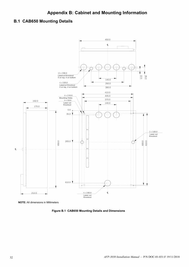
3
Appendix B: Cabinet and Mounting Information
B.1 CAB650 Mounting Details
450.0
650.
0
212.0
170.0
192.0140.0370.0
410.0
600.
061
0.0
35.0
0.0
265.0
610.0
405.0
260.0140.0
380.0
22.5
35.0
4 x D25.0Lasercut Knockout2 on top, 2 on bottom
10 x D50.0Lasercut Knockout5 on top, 5 on bottom
4 x D5.0Laser cut Knockout
2 x D25.0 Laser cutKnockout
4 x D10.0Mounting Holes
4 x D50.0
Laser cutKnockout
Figure B.1 CAB650 Mounting Details and Dimensions
NOTE: All dimensions in Millimeters
AFP-3030 Installation Manual — P/N DOC-01-031:F 19/11/20182

CAB900 Mounting Details Cabinet and Mounting Information
B.2 CAB900 Mounting Details
Figure B.2 CAB900 Mounting Details and Dimensions
NOTE: All dimensions in Millimeters
192
212
140.0370.0405.0410.0
265.0
0.0
515.0
35.0
860.0
860.
0
850.
0
450.0
900.
0
260.0140.0
380.0
22.5
35.0
4 x D50Laser cutKnockouts
4 x D25Laser cutKnockouts
4 x D10Mounting holes
4 x D5.0Laser cut
Knockouts
10 x D50.0Laser cut knockouts5 on top, 5 on bottom
4 x D25.0Laser cut knockouts2 on top, 2 on bottom
AFP-3030 Installation Manual — P/N DOC-01-031:F 19/11/2018 33
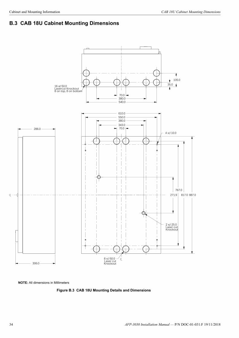
Cabinet and Mounting Information CAB 18U Cabinet Mounting Dimensions
B.3 CAB 18U Cabinet Mounting Dimensions
Figure B.3 CAB 18U Mounting Details and Dimensions
NOTE: All dimensions in Millimeters
70.0
380.0550.0
817.0767.0
610.0
887.0
286.0
306.0
343.0
271.9
8 x 50.0Laser cutKnockout
4 x 10.0
2 x 25.0Laser cut Knockout
70.0380.0540.0
35.0105.0
16 x 50.0Lasercut Knockout8 on top, 8 on bottom
34 AFP-3030 Installation Manual — P/N DOC-01-031:F 19/11/2018
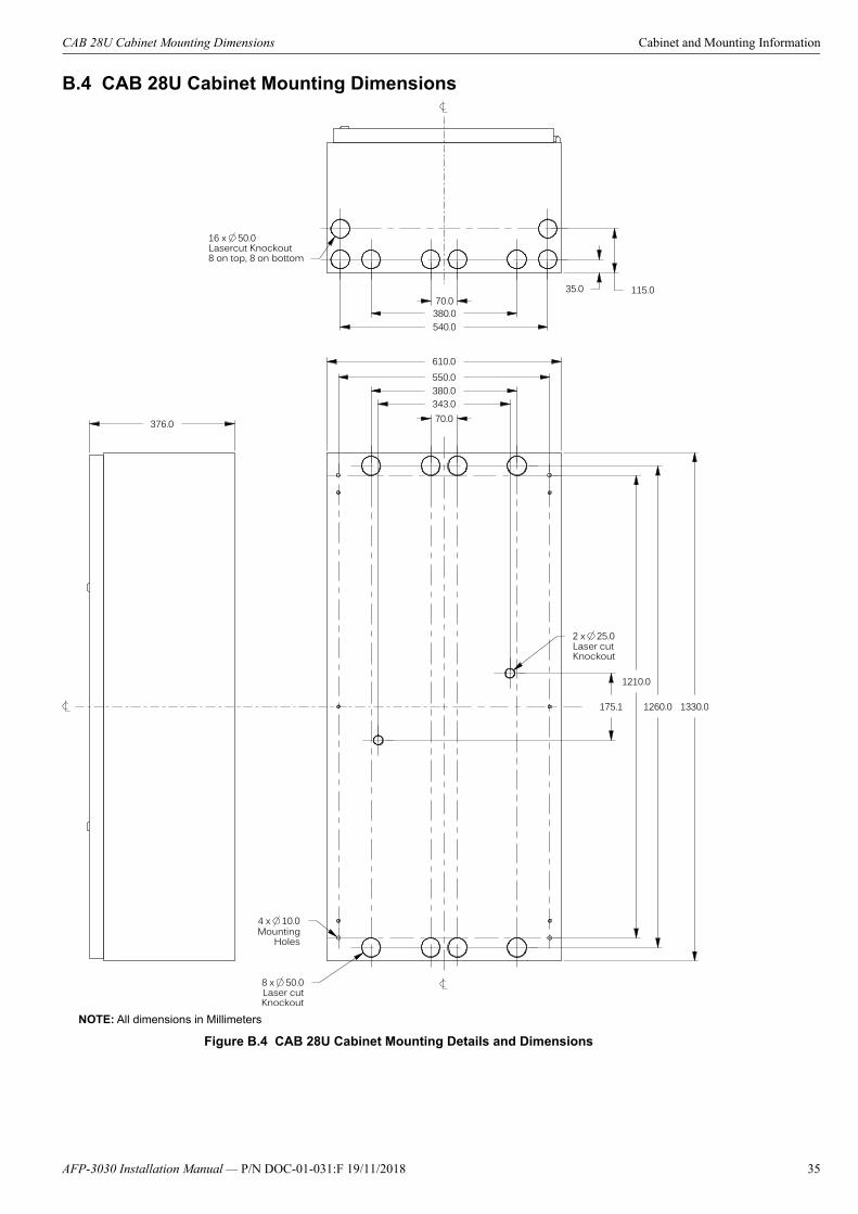
CAB 28U Cabinet Mounting Dimensions Cabinet and Mounting Information
B.4 CAB 28U Cabinet Mounting Dimensions
Figure B.4 CAB 28U Cabinet Mounting Details and Dimensions
NOTE: All dimensions in Millimeters
1330.0
376.0 70.0
380.0550.0
343.0
1260.0
1210.0
175.1
8 x 50.0Laser cutKnockout
4 x 10.0
2 x 25.0Laser cut Knockout
610.0
70.0380.0540.0
35.0 115.0
16 x 50.0Lasercut Knockout8 on top, 8 on bottom
MountingHoles
AFP-3030 Installation Manual — P/N DOC-01-031:F 19/11/2018 35

Cabinet and Mounting Information CAB 40U Cabinet Mounting Dimensions
B.5 CAB 40U Cabinet Mounting Dimensions
Figure B.5 CAB 40U Cabinet Mounting Details and Dimensions
NOTE: All dimensions in Millimeters
70.0
380.0343.0
550.0
1795.0
1745.0
707.5 1865.0
376.04 x 10.08 x 50.0
Laser cutKnockout
2 x 25.0Laser cut Knockout
610.0
70.0380.0540.0
35.0 105.0
16 x 50.0Lasercut Knockout8 on top, 8 on bottom
36 AFP-3030 Installation Manual — P/N DOC-01-031:F 19/11/2018

Laying Out Equipment in Cabinet and Chassis Cabinet and Mounting Information
B.6 Laying Out Equipment in Cabinet and Chassis The AFP-3030 allows for flexible system design. It mounts in a CAB650 or CAB900 backbox using the CHS-3L or in a U-Series back-box using the CHS-4L. Follow these guidelines when deciding where to locate equipment in the backbox. The number of layers that can be mounted in each position of the chassis depends on the module size.
CHS-3L
The CPU and power supply assembly mount in the top row of the CAB650 or CAB900 cabinet. The AFP-3030 keypad is door mounted in front of the CPU and power supply assembly. The CHS-3L Chassis is mounted below the CPU and power supply assembly.
In the CAB900, a second CHS-3L Chassis can be installed below the first for additional equipment.
CHS-4L
The CPU and power supply assembly mount in the top row of the U-Series cabinet. The AFP-3030 keypad is door mounted in front of the CPU and power supply assembly. The CHS-4L Chassis is mounted below the CPU and power supply assembly.
In the 28U and 40U cabinets, additional CHS-4L Chassis can be installed below the first for additional equipment.
B.7 Installing Replacement Equipment
B.7.1 Installing a replacement keypadThe keypad enables the user to operate and program the fire panel.
1. Open the cabinet inner door and unplug the ribbon cable connecting the keypad to the CPU board.2. From the cabinet inner door, remove:
a. The flanged nuts from the inner door studs.
!CAUTION:
IT IS CRITICAL THAT ALL MOUNTING HOLES OF THE FIRE ALARM CONTROL PANEL ARE SECURED WITH A SCREW OR STAND-OFF TO INSURE CONTINUITY OF EARTH GROUND.
Figure B.6 Chassis CHS-3L
1
2
3
Three positions on chassis CHS-3L
CH
S-3
L-
Figure B.7 Chassis CHS-4L
Chs
-4L.
jpg
1
2
3
Four positions on chassis CHS-3L
4
!CAUTION: POWER DOWN THE FIRE PANEL BEFORE FITTING THE KEYPAD.
AFP-3030 Installation Manual — P/N DOC-01-031:F 19/11/2018 37
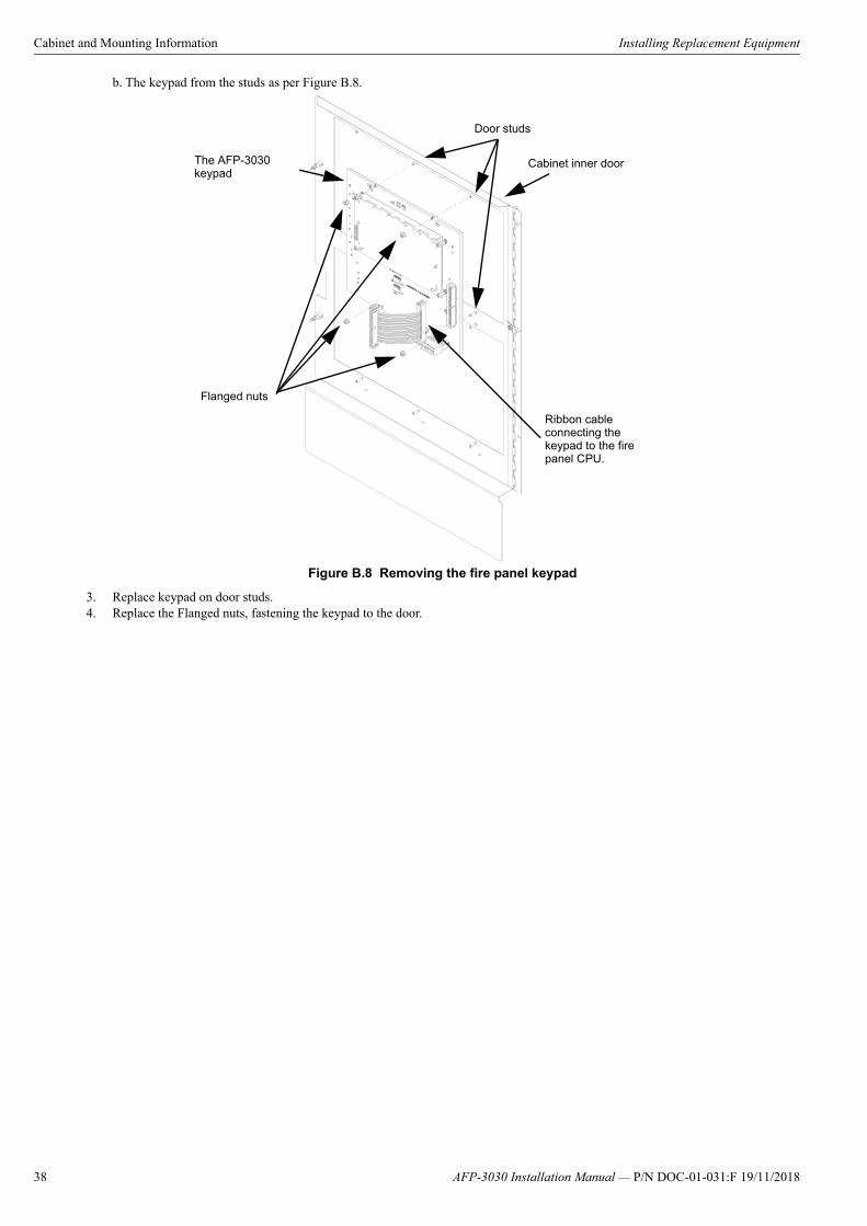
Cabinet and Mounting Information Installing Replacement Equipment
b. The keypad from the studs as per Figure B.8.
3. Replace keypad on door studs.4. Replace the Flanged nuts, fastening the keypad to the door.
Figure B.8 Removing the fire panel keypad
Ribbon cable connecting the keypad to the fire panel CPU.
Cabinet inner doorThe AFP-3030 keypad
Door studs
Flanged nuts
38 AFP-3030 Installation Manual — P/N DOC-01-031:F 19/11/2018

39AFP-3030 Installation Manual — P/N DOC-01-031:F 19/11/2018
Notes

AFP-3030 Installation Manual — P/N DOC-01-031:F 19/11/201840
Index
AAlarm Relays see Relays 17
BBackboxes 8, 10Battery
Battery Calculations 27, 28, 30–31Battery Checks 25Memory-Backup Battery 13
BMP-1 37
CCabinets, also see Backboxes 8, 37Chassis
CHS-3L 37Circuit Board, also see CPU 9Control Panel Circuit Board, also see CPU 9CPU 9
Drawing 9Installation Steps 37
DDoors 8, 10Dress Panels 8DS-DB 30DVC-RPU 30
EElectrical Connections 18Electrical Specifications 27
HHS-NCM-W/F
Mounting 14
IIndicating Device Circuits, also see NACs 27Installation
Checklist 12Preparation 12
LLCM-320/LEM-320, see SLC Loop Modules
MMain Power Supply 10Maintenance 25Manual Pull Station 23Memory-Backup Battery
Insulator 13
NNACs
Specifications 27NCM-W/F
Mounting 14Networking 14Notification Appliance Circuits, also see NACs 27
OOperating Power 27Operational Checks 25
Output Relays, also see Form-C RelaysSpecifications 17
PPC Connection 24Power
AC Power Checklist 21Auxiliary Power 22Installation Steps 18Locally Powered Devices 19Main Power Supply 10Power Supply Calculations 27, 28, 30–31PSU Switch 21Remote Device Powered By Local Device
19Specifications 18Terminating mains supply 18
Printers 23Installation 22PRN Printer Settings 23
RRelated Documentation 5
SSignalling Line Circuit, also see SLC 23SLC Loop Modules
SLC Loop Number 15SLC, also see SLC Wiring Manual
Specifications 27Specifications 27
Environmental Specifications 8Supply Ratings 8
Supervisory Relays, also see Relays 17Supplemental Documentation 5System
Features 7Limitations 7Options 7System Description 7
System Current Draws 27, 28, 30–31
TTesting 25Trouble Relays, also see Relays 17
UUpload/Download Software 24
VVeriFire® Tools 24
WWiring, also see SLC 23
Wire Requirements 27

AFP-3030 Installation Manual — P/N DOC-01-031:F 19/11/2018

New South Wales(Head Office)9 Columbia WayBaulkham Hills NSW2153
ph +61 (0)2 9894-1444www.notifier.com.au
New Zealand56 Cawley St Potts StreetAUCKLAND, NZ1051
ph +64 (0)9 623-5275www.notifier.co.nz