installation manual for weka boxcoolers · weka_inst_manual_boxcoolers_20140310 1 . installation...
TRANSCRIPT

WEKA_Inst_Manual_Boxcoolers_20140310
1
INSTALLATION MANUAL FOR WEKA BOXCOOLERS WEKA BOXCOOLERS B.V. INDUSTRIEWEG 8 NL-2921 LB KRIMPEN A/D IJSSEL NETHERLANDS
Phone +31 180 516 588 Fax +31 180 516 064 E-mail address [email protected] Website WekaBoxcoolers.com

WEKA_Inst_Manual_Boxcoolers_20140310
2
1. INTRODUCTION 4
1.1 Guarantee and liability 4
1.2 Receipt of goods 4
2. PREPARATIONS BEFORE INSTALLATION 5
2.1 Shape of sea-chest 5
2.2 Clearance for dismantling and cleaning 5
2.3 Sea-chest construction 5
2.4 Orientation & Leveling 5
2.5 Inlet- and Outlet grids in the ship’s hull 6
2.5.1 Inlet grids 6 2.5.2 Outlet grids 6
2.6 Protection of ship’s hull 6 2.6.1 Sacrificial anodes in the sea-chest 6 2.6.2 ICCP Systems 7
2.7 Protection of Boxcooler 7 2.7.1 Temporary protection unit - WEKA Guard 7 2.7.2 Permanent protection unit - WEKA Protector 7
2.8 Fittings & Piping 8 2.8.1 Construction and nozzle load 8 2.8.2 Vents 8 2.8.3 Drains 8 2.8.4 Valves 8
2.9 Instructions for conservation 8 2.10 Leakage due to damaged tubes 8
3. UNPACKING 9
3.1 Steps to be followed during unpacking of the Boxcooler 9
3.2 Hoisting instruction 9 3.2.1 Hoisting tools 9 3.2.2 Rotating the tube bundle 9
4. INSTALLATION 11 4.1 Cut-out in, Mounting frame and final painting 11

WEKA_Inst_Manual_Boxcoolers_20140310
3
4.2 Installation of the Boxcooler 11 4.3 Electric insulation from the ship’s hull 12
5. START-UP OPERATION 13
5.1 Connection of protectors 13
5.2 Dirt removal 13
5.3 Operating procedures 13
5.3.1 Start-up 13 5.3.2 Shut-down operation 13 5.3.3 Inhibitors 13 5.3.4 Bolted joints 13
6. MAINTENANCE 14
6.1 Inspection 14
6.2 Cleaning 14
6.3 Locating tube leaks when loosing coolant 14
7. PERFORMANCE FAILURES 15
ATTACHMENT I BOXCOOLER EXPLODED VIEW
ATTACHMENT II MOUNTING PRINCIPLE
ATTACHMENT III HOISTING WITH EYE-BOTLS
ATTACHMENT IV HOISTING WITH HOISTING BAR
ATTACHMENT V HOISTING WITH HOISTING BEAMS
ATTACHMENT VI FITTING MOUNTING FRAME TO TOPPLATE
ATTACHMENT VII INSTALLING TUBE BUNDLE
ATTACHMENT VIII INSTALLING THE BONNET
ATTACHMENT IX PLACEMENT OF SACRIFICIAL ANODES IN THE SEACHEST
ATTACHMENT X PLUG FOR LEAKING TUBES
ATTACHMENT XI INSTRUCTIONS FOR INLET AND OUTLET SLOTS

WEKA_Inst_Manual_Boxcoolers_20140310
4
INTRODUCTION • Read this instruction manual before proceeding with installation of WEKA Boxcooler • Important documents besides this instruction manual are the order confirmation, the specification sheet and drawings.
1.1 Guarantee and liability The “General conditions of sale of WEKA Boxcoolers BV” are applicable. Also refer to the order confirmation for possible additions.
1.2 Receipt of goods • Upon receipt of goods, please report any damage or discrepancy to WEKA Boxcoolers BV • Compare the data on the identification plate, order confirmation and on the drawing • Always store the Boxcoolers in a dry room with stable temperature conditions • When the Boxcooler is not put into operation immediately after receipt, then follow the “Instruction for conservation”

WEKA_Inst_Manual_Boxcoolers_20140310
5
2. PREPARATIONS BEFORE INSTALLATION 2.1 Shape of sea-chest The water content of the sea-chest has no significant influence on the thermal behavior of the Boxcooler. The shape of the sea-chest is not critical, as long as there is a free space around the Boxcoolers bundle of not less than 150mm. The shape of the top-plate is of great influence for the cooling. No flow restrictions may be used on the underside of the top-plate, to guarantee a smooth flow to the outlet grids. Preferably the top plate near the outlet grids should be inclined (e.g. 10 degrees) to improve the water circulation to the outlet as well as the de-aeration of the sea-chest. Preferably the sea-chest should allow withdrawal of the tube stack without dry-docking the ship. This can be realized by several means such as:
• Observing the waterline • Trimming the ship • Implementing a ‘ cofferdam’
In case more than one Boxcooler is needed for the thermal duty, Boxcoolers can either be connected in series or in parallel.
2.2 Clearance for dismantling and cleaning Provide sufficient clearance above the Boxcooler to permit withdrawal and replacement of the tube bundle. It may be desirable to provide extra flange connections in the piping near the Boxcooler to make an easy dismounting possible.
2.3 Sea-chest construction The top-plate of the sea-chest must be constructed for bearing the complete Boxcooler. A weak construction may lead to leakage between bundle and mounting frame. The top of the mounting frame, which is welded to the top-plate of the sea-chest, must be fitted below or at the light-ship waterline. Install a permanent vent pipe DN50 (2”) or larger at the highest point on the top-plate of the sea-chest. The minimum distance between tube bundle and the sea-chest walls shall be 150 mm (6”) or larger to secure a proper water flow around the tubes. Near frames or reinforcement bars a minimum distance of 100 mm (4”) is required.
The sea-chest shall be designed so as to avoid stray currents. Open frames or other openings between sea-chest are not recommended. Should openings be required, WEKA should be consulted. Protective devices against ship corrosion, such as anodes, should not be placed in sea-chests. See also section 2.6.1
2.4 Orientation & Leveling The Boxcooler can be positioned both athwart-ships or longitudinally, see Attachment II. The Boxcooler must be set level and square so that pipe connections can be made without force. An inclined installation is only allowed after consulting WEKA Boxcoolers BV. If the low temperature system consist of more than one Boxcooler in series or parallel then each Boxcooler must be installed in a separate sea-chest. The frames between the various sea-chests should be either closed or completely open. Partly opened frames can cause local high velocities of sea-water which can cause serious damage to the Boxcooler.

WEKA_Inst_Manual_Boxcoolers_20140310
6
2.5 Inlet- and Outlets grids in the ship’s hull 2.5.1 Inlet grids (bottom) The actual required opening is stated on the Specification sheet of the Boxcooler. The grids must be oriented transversely on the sailing direction. This prevents too much turbulence and too high water velocities near the lower end of the bundle. The width of the grids must be not larger than 50 mm, length 500-600 mm. A pattern of holes is also acceptable. See attachment XI. The inlet grids need to be located in the lowest possible position just below the Boxcooler. The distance between the inlet-grids and the bundle must not be less than 150 mm (6”). This is to minimize the risk for unacceptable vibrations. Also in shallow, muddy waters, this configuration can be beneficial.
2.5.2 Outlet grids (side) The actual required opening is stated on the Specification sheet of the Boxcooler.
The grids must be oriented longitudinally to the sailing direction and must be positioned as high as possible in the sea-chest directly under the top-plate but still below the empty waterline. Maximum distance from underside of the top-plate to the uppermost outlet slot is 25 mm. The width of the grids must not be larger than 50 mm, length 500-600 mm. A pattern of holes is also acceptable. See Attachment XI.
The distance between the outlet grids and the bundle of the Boxcooler must be not less than 150 mm (6”).
Please contact WEKA Boxcoolers BV for having the total number and size of the grids estimated for the application. A drawing of the sea-chest with all relevant dimensions must be sent together with your request.
2.6 Protection of the ship’s hull 2.6.1 Sacrificial anodes in the sea-chest The ship needs to be protected from corrosion. Corrosion protection for the hull should not be placed in the sea-chest. Protective devices against ship corrosion, such as sacrificial anodes, may induce stray currents, which may damage the Boxcooler. Should anodes be required in a sea-chest, care must be applied as to their number, weight and position, in order to avoid the generation of potentially excessive stray currents. The size and placement of the anodes must relate to the design of the sea-chest and the placement of the Boxcooler. Please consult WEKA Boxcoolers BV for advice regarding the amount and placement of the sacrificial anodes.
Large sacrificial anodes may cause stray currents which may damage the Boxcooler. Reference is also made to sections 2.3 and 2.7.2.

WEKA_Inst_Manual_Boxcoolers_20140310
7
The following advice is given for general consideration.
Boxcoolers- as electrically (galvanically) isolated from the ship’s hull – are subject to damage by stray current. While WEKA Boxcoolers have WEKA Guard and WEKA Protector devices to protect from stray currents, excessive stray currents may damage even WEKA Boxcoolers. More information about stray currents may be found on WEKA’s web page.
If sacrificial anodes are prescribed for corrosion protection of the sea-chest, such anodes shall be placed at the bottom of the sea-chest, below the Boxcooler. The anodes should be equally spread at all sides on the bottom.
If sacrificial anodes are prescribed, the weight should be kept as low as possible. Unnecessarily large anodes may try to protect the ship’s hull also outside the sea-chest; the resulting stray current flows resulting may damage the Boxcooler. The weight per anode should in any case not exceed 2 kg. A schematic overview is shown in enclosure (Attachment IX).
2.6.2 ICCP Systems Where an ICCP (Impressed Current Cathodic Protection) system will be used on board, WEKA should be advised of the electrical output of the system (i.e. the current rating per anode) in order to advise the minimum distance between anode and Boxcooler sea-chest. In all cases the Dielectric Shield of the ICCP anode must never cover the Boxcoolers sea-chest grating.
2.7 Protection of the Boxcooler 2.7.1 Temporary protection unit - WEKA Guard In the shipment a device is included which protects the Boxcooler from damage by regular welding currents. This device (WEKA-Guard) must be connected to the Boxcooler and to the ship’s hull during the newbuilding process of the ship, when the ship-based electrical supply is not yet available. If not installed, the Boxcooler may suffer from severe corrosion due to welding currents. With Boxcoolers in place, welds must be made using the most modern and best available professional welding methods. Once the ship is completed and due for delivery, the WEKA Guard will be replaced by the WEKA Protector, which from this point takes over the protection of the Boxcooler. An instruction on how to connect the WEKA Guard is included in the shipment of the Boxcooler and can be downloaded from www.Boxcoolers.com.
2.7.2 Permanent protection unit - WEKA Protector WEKA strongly recommends the yard to install one WEKA Protector per Boxcooler. This protects the Boxcooler from damage by well designed and properly working regular ICCP-systems or by regular currents originating from small sacrificial anodes. The WEKA Protector is a small device, which is placed in the vicinity of the Boxcooler to be protected. An instruction on how to install and operate the WEKA Protector will be included in the shipment of the Boxcooler and can be downloaded from www.Boxcoolers.com.

WEKA_Inst_Manual_Boxcoolers_20140310
8
2.8 Fittings & Piping 2.8.1 Construction and nozzle load The piping must be constructed in a way that the Boxcooler can be mounted without any problems. The Boxcooler is not intended to serve as an anchor point for piping; this can result in over-stressing or damaging of the bonnet. Therefore the piping must be designed and installed in such a way that the piping loads on the Boxcooler are negligible.
2.8.2 Vents It is advisable to install vent valves in the piping for de-aeration of the system.
2.8.3 Drains The piping must be provided with drains near the Boxcooler. Installing valves on the drains is recommended.
2.8.4 Valves It may be desirable to provide valves in the piping systems to permit inspection and repairs without draining the complete system.
2.9 Instructions for conservation The Boxcooler is supplied without any conservation. In case the Boxcooler will not be installed immediately, we advise to treat the Boxcooler with a rust preventive liquid of a type suited for long term conservation. When necessary, contact a specialized company. Take the material of the Boxcooler (see Specification sheet) into consideration. Be aware that in uncontrolled storage conditions large amounts of water can accumulate in the heat exchanger as a result of condensation.
2.10 Leakage due to damaged tubes Leakage due to damaged tubes is normal, and in line with industrial experience. Each Boxcooler from WEKA is designed with a sufficient over-capacity. The Boxcooler is a cooling system, not only a number of tubes.
When a leakage is found (procedure described in Section 6.3), the leaking tube shall be plugged off at both ends. Plugs for this purpose are supplied with each order, can be ordered from WEKA, or can be easily produced by any mechanical workshop or on board ship in a lathe in copper or brass material. The form and dimensions can be found on the enclosed drawing. (Attachment X)

WEKA_Inst_Manual_Boxcoolers_20140310
9
3. UNPACKING Warning: The bundle of tubes can easily be damaged. Prevent this by removing the cover and sidewalls carefully!
Boxcoolers are generally packed in wooden cases. It is advised to unpack near the jobsite, to prevent damage.
3.1 Steps to be followed during the unpacking of the Boxcooler a. Remove the cover of the case. b. Take the mounting frame out of the case and weld it on top of the sea-chest. c. Close the case until the tube bundle is needed for installation. d. Remove the cover and sidewalls of the case. e. Remove the bonnet from the tube-sheet by removing the bolts. f. Rotate the tube bundle as described in section 3.2.2. g. Attach the hoisting beams or eye-bolts to make the tube bundle suitable for hoisting. Perform the hoisting as described in
section 3.2.
3.2 Hoisting instruction Hoisting of the Boxcoolers, and parts of it, may only be done by trained and skilled personnel. Use hoisting materials and tools, which are suited for the load. The weight of the tube bundles can be found on the Specification sheet of the Boxcooler.
3.2.1 Hoisting Tools For hoisting of the tube bundles there are three ways of hoisting; 1. Using four eye-bolts M12 (DIN580; C15). Four threaded holes are available in the tube-sheet for this purpose. Eye-bolts are
not supplied with the Boxcooler. Make sure the load is uniformly spread over all the eye-bolts. See Attachment III for details. 2. Using the hoisting bar and beam according to Attachment IV. These may be used for hoisting the tube bundle out of the
packaging and to the jobsite. These tools are not supplied with the Boxcooler. In Attachment IV details can be found to fabricate these parts.
3. Only applicable when hoisting beams according to Attachment V are supplied. Use the hoisting beams that are supplied with the Boxcooler. These beams must be fitted to the tube-sheet using M12 bolts with a minimum tensile strength of 500N/mm² (72500 psi). Four threaded holes are available in the tube-sheet for this purpose. See Attachment V for details.
Warning: Do not hoist the Boxcooler by using cables or chains that are put through the lane in the middle of the bundle or connected to a support plate. This may cause severe damage to the tube bundle.
3.2.2 Rotating the tube bundle Each tube bundle must be rotated using a hoisting procedure to get it into the mounting position (see figure below). The rotating must be performed on a flat sub-soil. Always use a protective material such as rubber between the sub-soil and the tube bundle to prevent damage. Rotating a tube bundle - which is standing on the tube sheet - by pushing it over and let it fall to the floor is not allowed.

WEKA_Inst_Manual_Boxcoolers_20140310
10

WEKA_Inst_Manual_Boxcoolers_20140310
11
4. INSTALLATION 4.1 Cut-out in, Mounting frame and final painting Cut a hole to the correct size in the top-plate of the sea-chest. Size of the cut-out is obtained using the dimensions A and C from the Specification sheet of the Boxcooler together with Attachment VI. Radius in each corner of the cut-out to be <50 mm. Place the mounting frame into position and weld it to the top-plate according to the right detail of figure below.
An extra protection with Hempel coating (or equal) is required for the top-plate and mounting frame. Please refer to www.Boxcoolers.com: Downloads – Information Material- Corrosion protection, for details.
Take precautions to prevent bending due to heat input. Large mounting frames have an extra reinforcement strip between the long sides. Do not remove this until the mounting frame is welded to the top-plate. Round all edges after welding – before the touch-up paint is applied. See also Attachment VI.
4.2 Installation of the Boxcooler Perform the following steps during installation of the Boxcooler.
Step 1: Place the mounting frame gasket (the gasket without web-pattern) into position on the mounting frame. Place the tube bundle into position on the mounting frame. For hoisting instructions see section 3.2. Install the hexagon socket head screws and washers in the stepped holes in the tube-sheet. First the plastic washer, then the metal washer and finally the hexagon head screw. Make sure there is a plastic bushing fitted in the hole of the tube-sheet. The metal washer must be mounted with the sloped side facing up. Tighten them with a wrench moment of 10-12 Nm. See Attachment VII for more details.
Conductive grease, such as copper slip, must not be applied.

WEKA_Inst_Manual_Boxcoolers_20140310
12
Step 2: Place the bonnet gasket (the gasket with web-pattern) on the tube-sheet and check if the gaskets web matches the lanes between the tubes and to the partition plates in the bonnet. Make sure there is an insulation bushing in each hole of the tube-sheet. Next, position the bonnet and install all hexagon bolts according to Attachment VIII. It is important that these bolts are tightened 3 times and use with a limitation of 20 Nm (14 lb ft) the first time. The maximum wrench moment is 50-60 Nm (35-45 lb ft). Note: Excessive tightening may endanger the electric insulation! (See section 4.3)
Step 3: Verify by measuring that the tube bundle is insulated from its surrounding parts. See section 4.3 for the applicable method. Step 4: Connect the piping.
4.3 Electric insulation from the ship’s hull To prevent corrosion of the sea-chest, and to safeguard the anti-marine growth characteristics of the Boxcooler, the tube bundle must be fully electrically insulated from the top-plate of the sea-chest. For this reason, the bolt holes are provided with insulation bushings. Verify during installation of the tube bundle that these bushings are present in each hole and that they are not broken. There shall be bushings for the hexagon socket head screw as well as for the hexagon bolts. See Attachment I.
After installing the complete Boxcooler including the bonnet, verify it is insulated from the rest of the ship.
That should be done as follows:
Tube bundle not in water Measure the resistance between the tube-sheet and a bare piece of the top-plate of the sea-chest. The resistance must be more than 500 Ω. Values under 50 Ω are not acceptable. Values between 50 Ω and 500 Ω need further investigation to determine the cause for these values.
Tube bundle in water Measure the potential (DC) between the tube-sheet and a bare piece of the top-plate of the sea-chest. The voltage should be approximately 350 mV. In case a very low voltage is measured (=0V) this indicates a short-circuit and a non-isolated Boxcooler.
Before Assembling After Assembling

WEKA_Inst_Manual_Boxcoolers_20140310
13
5. START-UP OPERATION The equipment is designed for use with the conditions specified on the identification plate, specification sheet and/or drawing. It must not be operated at conditions which exceed those specified.
5.1 Connection of protectors All nozzle openings must be inspected for foreign material. Protective plugs and covers may not be removed until just prior to connecting the piping.
5.2 Dirt removal The entire system shall be clean before starting operation. If foreign material can be expected, the use of strainers in the piping towards the heat exchangers is required.
5.3 Operating procedures
5.3.1 Start-up During start-up all vent valves should be opened and left open until all passages have been purged from air and are completely filled with fluid.
5.3.2 Shut-down operation When shutting down the system, the Boxcooler should be drained completely or filled with suitable antifreeze liquid when there is the possibility of freezing or corrosion damage. A complete draining of the tube bundle is only possible after disassembly of the bundle and pouring the water out the bundle.
5.3.3 Inhibitors There can be reasons to add an inhibitor to the circuit of the Boxcooler. Contact a specialized company, which can also check for harmfulness of the inhibitor to the materials of the Boxcooler (see Specification sheet for material of the tube bundle). Follow the instructions of the supplier for use of the inhibitor.
5.3.4 Bolted joints Due to normal relaxing of the gasket joints all external bolted joints require re-tightening after the Boxcooler has once reached its operating temperature. Re-tightening may only be done when the unit is cold and depressurized. The same wrench moments as mentioned in section 4.2, steps 1 and 2 are applicable.

WEKA_Inst_Manual_Boxcoolers_20140310
14
6. MAINTENANCE 6.1 Inspection At regular intervals, i.e. the docking periods of the ship, an examination shall be made of the exterior condition of the Boxcooler. The condition of the sea-chest is to be inspected with regard to dirt and anti-fouling paint. It is not necessary to examine the interior of the Boxcooler (the inside of the Boxcooler).
6.2 Cleaning Provided the Boxcooler is properly installed and electrical insulated from the ship’s hull, marine growth will not occur on the Boxcooler. Still, when dry-docking there is a possibility that the Boxcooler is or becomes dirty from mud or sand. Cleaning of the Boxcooler can easily be done from outside by using a high-pressure water jet. The tube-stack of the Boxcooler will probably have a greenish or brownish appearance. Don’t remove this layer since this consists of copper-oxide. The copper-oxide is a stable chemical fraction and is the very reason for why the Boxcooler shows anti-fouling growth characteristics.
6.3 Locating leaking tubes when loosing coolant Extreme weather conditions, collision and objects entering the sea-chest can damage the tube bundles of the Boxcooler and cause leakages of the pipes. If this happens there are ways to overcome the problems and to repair the leaking pipes: The ship is afloat Depressurize and drain the freshwater cooling system by closing off the valves on the inlet- and outlet piping of the Boxcooler. The ship must be trimmed to make sure the top of the tube-sheet is below the waterline. Loosen the hexagon bolts but do not remove them. Wait until the coolant has leaked out under the bonnet. If water leaks between the tube-sheet and mounting frame, tighten the hexagon socket head bolts until leaking stops. Never loosen the hexagon socket head bolts when the ship is afloat!!!
After that, the hexagon bolts and the bonnet can be removed. Due to the pressure acting on the outside of the tube bundle, the water will make it visible which tube is leaking.
Leaking tubes can be plugged off with conical plugs (copper or brass). Do not apply too much force when installing a plug. This will cause deformation of the tube-sheet that will result in leakage of the surrounding tubes. Conical plugs of the correct size are obtainable from WEKA Boxcoolers BV. The ship is in dry-dock Depressurize and drain the freshwater cooling system by closing off the valves on the inlet- and outlet piping of the Boxcooler.
Dismount the Boxcooler from the sea-chest. Fit the bonnet and the bonnet gasket to the tube-sheet and blind all nozzle openings. Test the Boxcooler with hydraulic pressure or compressed air (submerge Boxcooler in water) applying the pressure stated on the identification plate. At the point where water or air appears, the tube bundle is leaking. Again, plug off the leaking pipes as described above.

WEKA_Inst_Manual_Boxcoolers_20140310
15
7. PERFORMANCE FAILURES The failure of the Boxcooler to perform satisfactorily may be caused by one or more factors, such as:
- Excessive fouling at the outside of the tubes. - The Boxcooler is not installed correctly. - Electrical insulation between tube-sheet and hull fails.
Solution: - Clean tube bundle according to section 6.2 - Re-install the Boxcooler to obtain electrical acc. to section 4.3.
b. Presence of air or gas resulting from improper piping installation or lack of suitable vents.
Solution : Ventilate complete system
c. Restricted outboard water flow.
Solution : - Check the inlet and outlet for an unrestricted entrance. - Check for air-traps in the upper region of the sea-chest. - Check the size of the openings and/or consult WEKA Boxcoolers BV
d. Operating conditions differ from design conditions.
WEKA_Inst_Manual_Boxcoolers_20140310
16
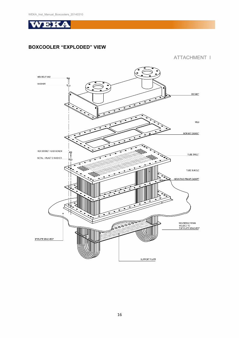
BOXCOOLER “EXPLODED” VIEW
ATTACHMENT I

WEKA_Inst_Manual_Boxcoolers_20140310
17
Mounting Principle
ATTACHMENT II
LONGITUDINAL MOUNTING
ATHWARTSHIP MOUNTING
HOISTING WITH EYE-BOLTS

WEKA_Inst_Manual_Boxcoolers_20140310
18
ATTACHMENT III
WEIGHT BUNDLE <600KG (13001b)

WEKA_Inst_Manual_Boxcoolers_20140310
19
±0.6"
HOISTING BEAM
HOISTING BAR TUBE (Ø 32mm*4mm) LINED WITH RUBBER
HOISTING WITH HOISTING BAR
ATTACHMENTA ATTACHMENT IV
MAXIMUM LOAD: 1100 kg (2400lbs)
HOISTING BEAM
MEASUREMENTS IN mm
INSERT HOISTING LUGS IN 11mm GAPS BETWEEN
HOISTING LUG, 2’ REQUIRED
DIMENSION IN mm: 1" = 25.4 mm MATERIAL: A106B/St. 37

WEKA_Inst_Manual_Boxcoolers_20140310
20
HOISTING WITH HOISTING BEAMS
ATTACHMENT V
WEIGHT BUNDLE >400 KG (880lbs)

WEKA_Inst_Manual_Boxcoolers_20140310
21
FITTING MOUNTING FRAME TO TOPPLATE
ATTACHMENT VI
TYPICAL CROSS - SECTION
TOP VIEW
-SIZE OF THE HOLE TO BE CUT IN THE TOP-PLATE OF THE SEA-CHEST: LENGTH(minimum) = A-100mm (A-4") WIDTH (minimum) = C - 100mm (C - 4) -BRING THE MOUNTING FRAME INTO POSITION AND WELD IT TO THE TOP PLATE OF THE SEA-CHEST
EDGES ROUNDED R=3mm (1/8") minimum

WEKA_Inst_Manual_Boxcoolers_20140310
22
INSTALLATION TUBE BUNDLE
ATTACHMENT VII
INSTALLING THE TUBE BUNDLE TO THE MOUNTING FRAME - PUT THE MOUNTING FRAME GASKET ON THE MOUNTING FRAME - SECURE THE HOISTING TOOL TO THE THREADED HOLES IN THE TUBE-SHEET (SEE ATTACHMENT III AND V), AND
PLACE THE BUNDLE INTO POSITION - INSTALL THE HEXAGON BOLTS INCLUDING THE WASHERS, METAL- AND PLASTIC RINGS.

WEKA_Inst_Manual_Boxcoolers_20140310
23
INSTALLING THE BONNET
ATTACHMENT VIII
INSTALLING THE BONNET TO THE TUBE-SHEET / MOUNTING FRAME
- POSITION THE BONNET GASKET ON THE TUBE-SHEET - SECURE THE BONNET TO THE TUBE-SHEET / MOUNTING FRAME BY MEANS OF THE M12 HEXAGON
BOLTS.
BOLT TIGHTENING PROCEDURE
- FOLLOW A DIAMETRICALLY STAGGERED PATTERN (AS ILLUSTRATED) - APPLY A WRENCH MOMENT OF 10-12 Nm - REPEAT THIS PATTERN 2 TO 3 TIMES. - THE MAXIMUM WRENCH MOMENT IS 50-60 Nm.

WEKA_Inst_Manual_Boxcoolers_20140310
24
PLACEMENT OF THE SACRIFICIAL ANODES IN SEA-CHEST ATTACHMENT IX
SPREAD AT ALL SIDES
WEIGHT PER ANODE NOT TO EXCEED 2 KG

WEKA_Inst_Manual_Boxcoolers_20140310
25
PLUG FOR LEAKING TUBES ATTACHMENT X
MEASUREMENTS IN mm
MATERIAL: COPPER OR BRASS

WEKA_Inst_Manual_Boxcoolers_20140310
26
INSTRUCTIONS FOR INLET AND OUTLET SLOTS
ATTACHMENT XI
NOTE: TOTAL REQUIRED OPENING AREA FOR INLET AND OUTLET RESPECTIVELY IS GIVEN FROM SPECIFICATION SHEET OF THE BOXCOOLER INSTALLED