installation manual sb-210+ 30 domestic refrigerated...
TRANSCRIPT
Installation Manual
SB-210+ 30 Domestic Refrigerated Container (DRC) UnitSingle Temperature SystemTK 54654-5-IM (Rev. 0, 12/10)
Copyright© 2010 Thermo King Corp., Minneapolis, MN, U.S.A.
Printed in U.S.A.

2
Release History
Released (12/10)

3
Domestic Refrigerated Container (DRC)
4
Introduction
This manual was written to assist with the installation of the Thermo King SB-210+ 30 Single Temperature refrigeration systems onto a Domestic
Refrigerated Container (DRC) that is specifically designed and built for refrigerated applications.
Due to its complexity, you should not attempt this installation unless you:
• Are an experienced mechanic
• Can safely lift 34 kilos (75 lbs.)
• Are certified or trained in the repair and maintenance of diesel powered refrigeration systems
• Have a basic understanding of electricity and electrical wiring
• Have the necessary tools and equipment to complete the installation.
This manual is published for informational purposes only. Thermo King makes no representations warranties express or implied, with respect to
the information recommendations and descriptions contained herein. Information provided should not be regarded as all-inclusive or covering
all contingencies. If further information is required, Thermo King Corporation Service Department should be consulted.
Thermo King’s warranty shall not apply to any equipment which has been “so installed, maintained, repaired or altered as, in the
manufacturer’s judgment, to affect its integrity.”
Manufacturer shall have no liability to any person or entity for any personal injury, property damage or any other direct, indirect,
special, or consequential damages whatsoever, arising out of the use of this manual or any information, recommendations or
descriptions contained herein.

5
Table of Contents
Safety Precautions . . . . . . . . . . . . . . . . . . . . . . . . . . . . . . . . . . . . . . . . . . . 6
Domestic Refrigerated Container (DRC) Requirements . . . . . . . . . . . . . . 8
SB-210+ 30 Unit Dimensions . . . . . . . . . . . . . . . . . . . . . . . . . . . . . . . . . . 9
Evaporator Opening Requirements . . . . . . . . . . . . . . . . . . . . . . . . . . . . . 10
Mounting Hardware Requirements . . . . . . . . . . . . . . . . . . . . . . . . . . . . . 12
Bulkhead Dimensions (Option) . . . . . . . . . . . . . . . . . . . . . . . . . . . . . . . . 14
Lifting Bar Dimensions . . . . . . . . . . . . . . . . . . . . . . . . . . . . . . . . . . . . . . 16
Required Tools . . . . . . . . . . . . . . . . . . . . . . . . . . . . . . . . . . . . . . . . . . . . . 18
Installation Components . . . . . . . . . . . . . . . . . . . . . . . . . . . . . . . . . . . . . 20
Unpacking the Unit . . . . . . . . . . . . . . . . . . . . . . . . . . . . . . . . . . . . . . . . . 22
Installing the Unit . . . . . . . . . . . . . . . . . . . . . . . . . . . . . . . . . . . . . . . . . . 24
Installing the Exhaust Extension . . . . . . . . . . . . . . . . . . . . . . . . . . . . . . . 26
Installing the Drain Hoses . . . . . . . . . . . . . . . . . . . . . . . . . . . . . . . . . . . . 28
Installing the Bulkhead (Option) . . . . . . . . . . . . . . . . . . . . . . . . . . . . . . . 30
Installing the Fuel Tank . . . . . . . . . . . . . . . . . . . . . . . . . . . . . . . . . . . . . . 32
Installing the Fuel Lines . . . . . . . . . . . . . . . . . . . . . . . . . . . . . . . . . . . . . 34
Installing the Fuel Level Sensor Harness (Option) . . . . . . . . . . . . . . . . . 36
Installing the Battery . . . . . . . . . . . . . . . . . . . . . . . . . . . . . . . . . . . . . . . . 38
SR-2 Programming Procedures . . . . . . . . . . . . . . . . . . . . . . . . . . . . . . . . 40
SYSTEM CHECK LIST. . . . . . . . . . . . . . . . . . . . . . . . . . . . . . . . . . . . . . 41

6
Safety Precautions
The symbol appears next to a point that is particularly important:
DANGER: Addresses a circumstance that, if encountered, will lead to death or serious injury
WARNING: Addresses a circumstance that, if encountered, might lead to death or serious injury.
CAUTION: Addresses a circumstance that, if encountered, may cause damage to equipment or minor injury.
DANGER: Never operate the unit with the discharge valve closed because it could cause the compressor to explode, causing death or serious injury.
DANGER: Never apply heat to a sealed refrigeration system or container because it could explode, causing death or serious injury
DANGER: Fluorocarbon refrigerants, in the presence of an open flame or electrical short, produce toxic gases that are severe respiratory irritants capable of causing death.
DANGER: Be careful when working with a refrigerant or refrigeration system in any enclosed or confined area with a limited air supply (i.e., a trailer, container or the hold of a ship). Refrigerant tends to displace air and can cause oxygen depletion which may result in death by suffocation.
WARNING: Always wear goggles or safety glasses. Refrigerant liquid, refrigeration oil, and battery acid can permanently damage the eyes (see First Aid under Refrigeration Oil).
WARNING: Keep your hands away from fans and belts when the unit is running. This should also be considered when opening and closing the compressor service valves.
WARNING: Make sure gauge manifold hoses are in good condition. Never let them come in contact with a belt, fan motor pulley, or any hot surface.
WARNING: Make sure all mounting bolts are tight and are of correct length for their particular application
WARNING: Never drill holes in the unit unless absolutely necessary. Holes drilled into the unit may weaken structural components. Holes drilled into electrical wiring can cause fire or explosion.
WARNING: When using ladders to install or service refrigeration systems, always observe the ladder manufacturer’s safety labels and warnings. A work platform is the recommended method for installations.
WARNING: Exposed coil fins are very sharp and can cause painful lacerations.

7
Safety Precautions (continued)
Refrigerant
First Aid
FROST BITE: In the event of frost bite, the objectives of First Aid are to
protect the frozen area from further injury, to warm the affected area
rapidly and to maintain respiration.
EYES: For contact with liquid, immediately flush eyes with large amounts
of water and get prompt medical attention.
SKIN: Flush area with large amounts of lukewarm water. Do not apply
heat. Remove contaminated clothing and shoes. Wrap burns with dry,
sterile, bulky dressing to protect from infection/injury. Get medical
attention. Wash contaminated clothing before reuse.
INHALATION: Move victim to fresh air and use CPR or mouth-to-mouth
ventilation, if necessary. Stay with victim until arrival of emergency
medical personnel.
Refrigeration Oil
First Aid
NOTE: In case of eye contact, immediately flush with plenty of water
for at least 15 minutes. CALL A PHYSICIAN. Wash skin with soap and
water.
WARNING: Although fluorocarbon refrigerants are classified as safe refrigerants, certain precautions must be observed when handling them or servicing a unit in which they are used. When released to the atmosphere in the liquid state, fluorocarbon refrigerants evaporate rapidly, freezing anything they contact.
WARNING: Avoid refrigeration oil contact with the eyes. Avoid prolonged or repeated contact of refrigeration oil with skin or clothing. Wash thoroughly after handling refrigeration oil to prevent irritation.

8
Domestic Refrigerated Container (DRC) Requirements
Approximate Weight of SB-210+ 30 (refrigeration unit only) = 742 kg (1635 lbs.)
Front Wall Requirements
Evaporator Opening RequirementsIMPORTANT: The location of the evaporator opening in the front wall
of the container is critical to the proper installation and operation of
the Thermo King unit. See “Evaporator Opening Requirements” on
pages 10-11.
Unit Mounting Hardware
IMPORTANT: The location of the unit mounting bolts in the front wall
of the container is critical for proper unit installation. See “Mounting
Hardware Requirements” on pages 12-13.
Fuel Tank Mounting
Unit Dimensions
Adequate clearance must be provided to allow for routine service and
maintenance of the Thermo King unit. See “SB-210+ 30 Unit Dimensions”
on page 9.
DANGER: The front wall of the container must be structurally strong enough to support the combined weight of the Thermo King refrigeration unit, the fuel tank with mounting hardware, and the full capacity of diesel fuel!
DANGER: The use of mounting hardware other than specified for installing the refrigeration unit could result in severe damage to equipment, void the warranty or cause personal injury or death!
DANGER: An improperly installed fuel tank could lead to serious injury or death! Consult your container, trailer or rail car manufacturer for specific details on proper fuel tank installation and recommendations.

9
SB-210+ 30 Unit Dimensions

10
Evaporator Opening Requirements
Evaporator Opening RequirementsIMPORTANT: The location of the evaporator opening in the front wall
of the container is critical for the proper installation and operation of
the Thermo King unit. VERIFY ALL DIMENSIONS BEFORE
INSTALLING UNIT!
1. The evaporator opening must be square and the diagonal measurements
must be ±3.0 mm (0.12 in.)
2. The gasket surface around the opening must be at least 76.2 mm
(3.00 in.) wide, be flat ±3.2 mm (0.05 in.) and free of rivets, seams or
bolt heads.

11
Evaporator Opening Requirements

12
Mounting Hardware Requirements
Unit Mounting Hardware
IMPORTANT: The location of the unit mounting bolts in the front wall
of the container is critical for proper unit installation.
All UNIT mounting hardware must be:
• Mounting bolts must be square with the front wall and securely
fastened to the container to allow the mounting nuts be torqued to
82 N•m (60 ft. lbs.) from outside the container.
• Mounting bolts must be 1/2-13 UNC- 28 rolled thread, grade 5,
medium carbon steel, zinc plated with dichromate finish.
• Mounting bolts must extend a minimum 57.2 mm (2.25 in.) beyond
the front wall.
• Matching locking nuts and flat washers (supplied) must be used to
secure the unit.
DANGER: The use of mounting hardware other than specified for installing the refrigeration unit could result in severe damage to equipment, void the warranty or cause personal injury or death!

13
Mounting Hardware Requirements

14
Bulkhead Dimensions (Option)
THERMO KING RECOMMENDS USING A BULKHEAD
Bulkheads are available from authorized Thermo King Dealers
Return Airflow
Restrictions of the return airflow adversely affects the performance of the
unit. The area directly behind the evaporator return air inlet must not be
restricted.
Bulkhead Function
A bulkhead is used to keep the return airflow from being restricted if the
load shifts. The bulkhead also prevents the load from shifting into the
return airflow passageway on the front wall of the inter modal container.

15
Bulkhead Dimensions (Option)
16
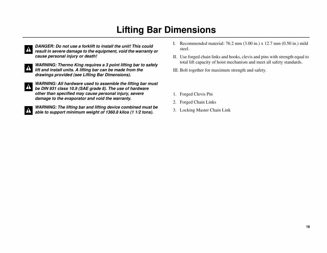
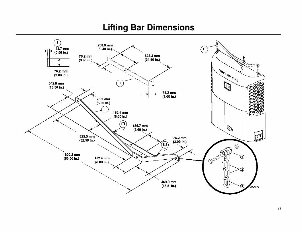
Lifting Bar Dimensions
I. Recommended material: 76.2 mm (3.00 in.) x 12.7 mm (0.50 in.) mild
steel.
II. Use forged chain links and hooks, clevis and pins with strength equal to
total lift capacity of hoist mechanism and meet all safety standards.
III. Bolt together for maximum strength and safety.
1. Forged Clevis Pin
2. Forged Chain Links
3. Locking Master Chain Link
DANGER: Do not use a forklift to install the unit! This could result in severe damage to the equipment, void the warranty or cause personal injury or death!
WARNING: Thermo King requires a 3 point lifting bar to safely lift and install units. A lifting bar can be made from the drawings provided (see Lifting Bar Dimensions).
WARNING: All hardware used to assemble the lifting bar must be DIN 931 class 10.9 (SAE grade 8). The use of hardware other than specified may cause personal injury, severe damage to the evaporator and void the warranty.
WARNING: The lifting bar and lifting device combined must be able to support minimum weight of 1360.8 kilos (1 1/2 tons).
17
Lifting Bar Dimensions

18
Required Tools
1. Safety Glasses
2. Drill
3. Drill Bits
4. Tape Measure
5. Mechanics Tools
6. Lifting Bar
7. Work Platform (Recommended)
8. Torque Wrench
9. Forged Eyebolts
NOTE: Equipment such as scales, gauges, refrigerant leak detectors,
and torque wrenches should be in good working condition and
routinely calibrated to assure accurate readings.

19
Required Tools

20
Installation Components
Unit Installation Components
1. Locking nuts 1/2-13
2. Washers 1/2 in.
3. Self tapping screws
4. Clamps
5. Cable ties
6. Fuel line fittings: 1/4 in. and 3/8 in.
7. Drain hose check valve
8. Exhaust pipe extension, hanger and clamps

21
Installation Components

22
Unpacking the Unit
Units are shipped attached to disposable wooden pallet and wrapped with
protective cardboard and plastic stretch wrap.
• To avoid unnecessary damage to your unit, place the crated unit
near the container prior to its removal.
• DO NOT use a sharp knife to remove the stretch wrap or cardboard
wrap as damage to the exterior of the unit will result!
Unpacking the Unit
• Carefully remove plastic stretch wrap from unit.
• Carefully remove the top cardboard cover.
• Carefully remove the outer cardboard wrap.
• Remove installation kit boxes, bottom panel, and any other loose
components from rear of unit.
• Remove the tie bands securing the fuel lines to the rear of the unit.
• Attach forged eyebolts and 3 point lifting bar to unit.
• Remove hardware holding unit to wooden pallet.
• Unit is now ready for installation.
DANGER: Do not use a forklift to install the unit! This could result in severe damage to the equipment, void the warranty or cause personal injury or death!
WARNING: Thermo King requires a 3 point lifting bar to safely lift and install units. A lifting bar can be made from the drawings provided (see Lifting Bar Dimensions).

23
Unpacking the Unit

24
Installing the Unit
Unit InstallationNOTE: Unbolt and remove any upper cross bracing or supports from
the container that interfere with the installation of the unit using the
3 point lifting bar.
1. Install two 5/8-11 forged lifting eyebolts (installer supplied) into
threaded holes located on the top of the unit (Detail I).
2. Attached the lifting bar to the both eyebolts and the unit support
bracket. Lift unit up to the front wall opening:
• Align the eight mounting studs on the container with the mounting
holes in the unit. Push the unit up flush with the front wall of the
container.
• Install the supplied locking nuts and flat washers onto each
mounting stud and tighten mounting hardware securely.
See Access to Mounting Holes (Detail II).
NOTE: All nuts that hold the unit to the container should be elastic
stop nuts (Nylock Type) provided in the installation kit.
Access to Mounting Holes (Detail II)
3. Top side mounting hole through the hinged roadside grille.
4. Center side mounting hole through hinged roadside grille.
5. Lower side mounting hole through hinged roadside panel and control
box hole.
6. Center side mounting hole through hinged lower curbside door.
7. Lower side mounting hole through hinged curbside panel.
8. Center side mounting hole through hinged curbside grille.
9. Top side mounting hole through hinged curbside grille.
10. Top center mounting hole from top of the unit.
NOTE: After the unit has been secured, reinstall any upper cross
bracing and supports that may have been removed from the
container earlier.
WARNING: Do not use a forklift to install the unit! This could result in severe damage to equipment, void the warranty or cause personal injury or death!
WARNING: Use only locking hooks to safely lift the unit! Failure to use locking hooks could result in severe damage to the equipment, void the warranty or cause personal injury or death! (Detail I).
WARNING: Thermo King requires a 3 point lifting bar to safely lift and install units. A lifting bar can be made from the drawings provided (see Lifting Bar Dimensions).

25
Installing the Unit

26
Installing the Exhaust Extension
Installation
1. Install the exhaust hanger onto the stud located on the container.
2. Install the extension pipe onto the end of the exhaust pipe of the unit.
3. Install exhaust clamps as shown and tighten securely.

27
Installing the Exhaust Extension
2
1
3
3

28
Installing the Drain Hoses
Installation
DRC applications typically have the fuel tank mounted directly under the
refrigeration unit which interferes with the drain hoses. The drain hoses
will need to be routed off to one side and down the container wall.
1. Route both drain hoses off to one side of the container.
2. Secure with screws and clamps provided in installation kit.
IMPORTANT: Drain hoses should run down from the unit with no
kinks or sharp bends.
3. Cut off excess hose and attach the drain hose check valves provided in
the installation kit onto the ends of each hose with cable ties.

29
Installing the Drain Hoses

30
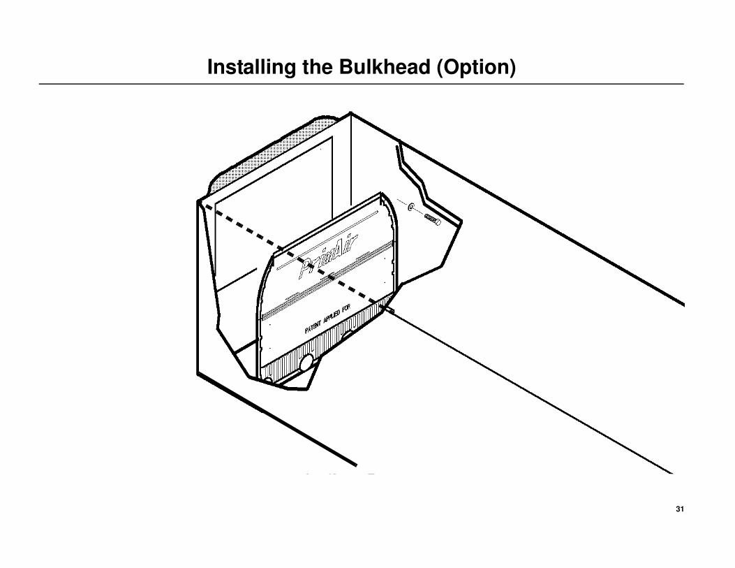
Installing the Bulkhead (Option)
THERMO KING RECOMMENDS USING A BULKHEAD
Bulkheads are available from authorized Thermo King dealers.
Return Airflow
Restrictions of the return airflow adversely affects the performance of the
unit. The area directly behind the evaporator return air inlet must not be
restricted.
Bulkhead Function
A bulkhead is used to keep the return airflow from being restricted if the
load shifts. The bulkhead also prevents the load from shifting into the
return airflow passageway on the front wall of the container.
Typical Bulkhead Shown
Follow bulkhead manufacturer specific details for proper installation and
recommendations.
CAUTION: Do not drill holes into refrigeration, electrical or mechanical components or severe damage to the equipment will result!
31
Installing the Bulkhead (Option)
32
Installing the Fuel Tank
Consult your container manufacturer for specific details on proper fuel tank installationand recommendations.

33
Installing the Fuel Tank
BLANK PAGE
34
Installing the Fuel Lines
Fuel Line Installation
1. Uncoil the fuel supply and return lines from the rear of the unit.
IMPORTANT: The fuel lines must remain routed through the provided
insulated clamp as shown, then down to the fuel tank.
2. Route the 3/8” FUEL SUPPLY line to the fuel tank fitting:
• The supply line when installed into the tank must be no higher than
25.4 mm (1.00 in.) from the bottom of the tank. Determine this
length and cut the supply line.
• Cut the end of the supply line at a 45 degree angle and slide on the
fuel line fittings.
• Insert the supply line into the fuel pickup fitting until it is 25.4 mm
(1.00 in.) from the bottom of the tank then tighten the fuel line
fitting securely.
3. Route the 1/4” FUEL RETURN line to the fuel tank:
• Cut the return line to the appropriate length and slide on the fuel
line fittings.
• Install the line onto the fuel return fitting and then tighten the fuel
line fitting securely.
4. Remove the plastic cap from the fuel vent and point the outlet to the
rear of the container.
NOTE: Add a sufficient amount of fuel (1/4 tank) to allow the unit to
run for 8 to 12 hours during engine break-in and pre-delivery
procedures.
DANGER: Leaking fuel lines could cause a fire resulting in death or serious injury! All fuel line fittings must be tight and leak free!
DANGER: Do not route fuel lines with battery cables or electrical wires, as this could cause a fire!

35
Installing the Fuel Lines
2 3
IMPORTANT: The fuel lines must remain routed through the
provided insulated clamp as shown, then down to the fuel
tank.

36
Installing the Fuel Level Sensor Harness (Option)
Wire Routing and Connections
1. Locate the short factory installed fuel level sensor harness with the
3-pin connector. This connector is located outside the control box and
cable tied to other harnesses at the rear of the unit near the frame
mounted ground plate.
• Apply a light coating of Superlube or equivalent to this connector.
• Connect the 6 ft. (1.8 m) fuel level sensor harness to the mating
3-pin connector on the factory installed harness.
• Route the harness to the fuel tank.
IMPORTANT: The use of the supplied crimp and solder style
connectors with separate heat shrink tubing is required when
connecting the fuel level sensor harness wires.
2. At the tank, connect the harness wires to the fuel level sensor wires
(wires are not polarity sensitive) by:
• Sliding supplied heat shrink tubing onto each wire and positioning
them away from the joint.
• Striping the wire ends, inserting them into the wire connectors and
crimping securely.
• Soldering the wires to the wire connectors with a soldering gun.
• Sliding the heat shrink tubing over the wire connectors and
applying heat with a heat gun.
3. Use supplied cable ties, clamps and screws to secure the harness as
shown.
IMPORTANT: See “SR-2 Programming Procedures” on page 40 to
enable the fuel level feature.
DANGER: Do not route electrical wires with fuel lines as this could cause a fire!

37
Installing the Fuel Level Sensor Harness (Option)

38
Installing the Battery
NOTE: Thermo King units are designed for one 12 volt, group 31
battery. The battery must be suitable for deep cycling, heavy duty
and rated with a minimum of 95 amp/hr.
1. Install the battery into the tray.
2. Install the battery hold down bracket and rods. Loosely install hardware
onto the rods.
NOTE: One of the hold down rods must fit into the notch located on
the channel under the battery. You may have to move the electrical
harness slightly to access this notch.
3. Align the tab of the battery hold down bracket over the two existing
holes in the frame support channel.
4. Install the two mounting bolts and flat washers through the hold down
bracket and support channel. Torque hardware to 13.5 N•m
(120 in-lbs).
5. Tighten the two battery hold down rods to 2.25 N•m (20 in -lbs.)
DO NOT over tighten as this may crack or distort the battery!
6. Install positive + battery cable on the positive battery post first to
minimize accidental electrical shorting. Tighten the bolt securely.
7. Install negative - battery cable on negative battery post second to
minimize accidental electrical shorting. Tighten the bolt securely.
CAUTION: Set all electrical controls to the OFF position before connecting the battery to prevent the unit from starting!
CAUTION: Always wear protective clothing, gloves and eye wear when handling and installing batteries!
CAUTION: Cover battery terminals to prevent accidental shorting during battery installation!

39
Installing the Battery
40
SR-2 Programming Procedures
Fuel Level
1. Enter the Guarded Access Menu.
2. Scroll down and select: Unit Configuration
3. Scroll down and select: Fuel Level Sensor.
The choices are: NONE, SOLID STATE and FLOAT.
• Scroll to FLOAT by pressing the + key then the YES key.
• Fuel Level Percent will now be in the gauge menu.
• Press the exit key.
• The unit is now programmed to indicate fuel level.
Remote Satellite Device (if applicable)
1. Enter the Guarded Access Menu.
2. Scroll down and select: Programable Features
3. Scroll down and select: Remote Device
The choices are: Enable/Disable.
• Scroll to Enable then press the + key then the YES key
• Press the exit key.
• The unit is now programmed to accept remote satellite
communications.

41
SYSTEM CHECK LIST
All unit mounting hardware torqued to specifications.
No air gaps between unit and container wall.
Drain hoses properly routed, secured with drain valves installed.
Fuel tank and mounting straps installed per tank manufacturers
specifications
Fuel lines properly routed and fuel fittings tightened securely.
Bulkhead (recommended) installed.
Battery secured and all connections clean and tight.
Doors closed and secured.
Run Pre-Trip test (refer to Host Unit Operating Manual).
Unit operated under load for eight hours to properly break-in engine.
Release to customer.