installation manual - the home depot manual 2 forward and important notes 3 product line .. 4—7...
TRANSCRIPT

Inspired by Nature……
NEXTSTONE™ INSTALLATION
MANUAL
2
Forward and Important Notes ………………………………………………… 3
Product Line ……………………………………………………………….. 4—7
Basic Tools …………………………………………………………………….. 8
Preparing the Wall ……………………………………………………….. 9—10
Starter Strip Installation ………………………………………………………. 11
Corner Installation ...………………………………………………….…. 12—19
Panel Installation ……………………………………………………….. 20— 24
Accent Rock Installation (for Random Rock Panels Only)……………………. 25
Trim Installation ………………………………………………………… 26—30
Mounting Block Installation …………………………………………………. 30
Column Wrap and Post Cover Installation………………………………. 31— 37
Mitered Corner Installation ……………………………………………... 38—39
Mailbox Installation …………………………………………………….. 40—43
Touch Up ……………………………………………………………………... 44
Clean Up …………………………………………………………………….. 45
Frequently Asked Questions ……………………………………………. 46—47
NextStone™ Take Off Guide …………….……………………..…………. 48—
51
Specification Data ……………………………..………….……………. 52— 54
Material Safety Data Sheet …………………….………………………… 55—56
Warranty Information ………………………………………………………... 57
CONTENTS

3
IMPORTANT NOTES
Compared to real or cast stone, NextStone™ polyurethane products are designed for an
easier, quicker installation requiring fewer steps. Masonry skills are not required. This
Manual provides basic guidelines for NextStone™ installation. Additionally, it is
recommended that Installers review applicable building codes for specific products and/
or geographic areas. This publication is not intended to provide specific advice, legal or
otherwise, on particular products or processes. Readers should consult with their own
legal and technical advisors, suppliers, and other appropriate sources including but not
limited to product or package labels, technical bulletins and sales literature that contain
information about known health and safety risks. NextStone™ does not assume any
responsibility for the users non-compliance of applicable laws and regulations.
This Installation Manual should be used as a guide for installation of NextStone™
Products. It is the responsibility of the Contractor and/or the Installer to ensure panels
are installed in accordance with these instructions and any applicable building codes.
The manufacturer assumes no liability for either improper installation or personal injury
resulting from improper use or installation.
STORAGE AND TRANSPORTATION All panels must be stored flat, in the box, at 65° Fahrenheit when possible, until ready
for installation. While polyurethane has minimal expansion and contraction, the effects
of expansion and contraction can be minimized by avoiding installation during periods
of extreme heat or cold. Do not store in direct sunlight before installing.
INSTALLATION BASICS
Never leave cut edges of NextStone™ products exposed. Exposed Polyurethane will
discolor with exposure to sunlight. Use NextStone™ touch-up paint or other color
match with a good quality latex paint. Drive the first screw on the right hand side of the
panel at a 45 degree angle to the left in order to tighten the panel into adjacent the panel,
corner or wall.
ACCLIMATION All products must be allowed to acclimate. Heat and moisture cause expansion. Best results are obtained by installing cool, dry product. NextStone™ does not warrant against gapping caused by expansion and contraction.
FORWARD

4
PRODUCT LINE
PANELS
Castle Rock Panel - Castle Rock Panels provide a more seamless design with vertical
stones. Panels dimensions are 43 ½" x 15 ¼" x 1 ¼" and cover 4.03 square feet each.
(4 panels per carton)
Slatestone Panel - Slatestone panels provide a faux look finish. Dimensions are
43" x 8 ¼" x 1 ¾" and cover 2.14 square feet. Stones vary from 1 ¼" to 2" in height and
have interlocking ends.
(8 panels per carton)
Stacked Stone Panel - Stacked Stone is the new and improved Drystack panel.
Dimensions are 46 ½" x 13 ¼" x 1 ½" and cover 3.63 square feet each. Stones vary in
height and the panels have interlocking ends. (
5 panels per carton)
Random Rock Panel - The original NextStone™ product with the look of quarried
stone. Panels dimensions are 15 ½" x 48" x 1½" and cover 4.75 square feet.
(4 panels per carton)
5
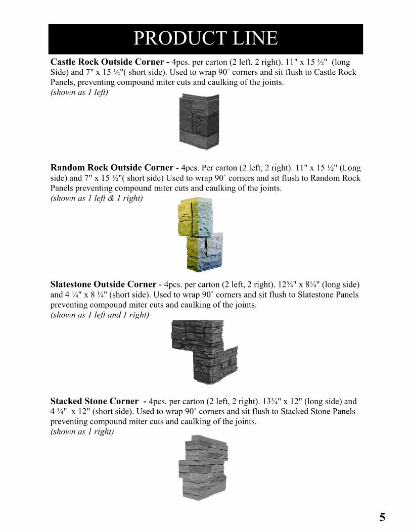
Castle Rock Outside Corner - 4pcs. per carton (2 left, 2 right). 11" x 15 ½" (long
Side) and 7" x 15 ½"( short side). Used to wrap 90˚ corners and sit flush to Castle Rock
Panels, preventing compound miter cuts and caulking of the joints.
(shown as 1 left)
Random Rock Outside Corner - 4pcs. Per carton (2 left, 2 right). 11" x 15 ½" (Long
side) and 7" x 15 ½"( short side) Used to wrap 90˚ corners and sit flush to Random Rock
Panels preventing compound miter cuts and caulking of the joints.
(shown as 1 left & 1 right)
Slatestone Outside Corner - 4pcs. per carton (2 left, 2 right). 12¾" x 8¼" (long side)
and 4 ¼" x 8 ¼" (short side). Used to wrap 90˚ corners and sit flush to Slatestone Panels
preventing compound miter cuts and caulking of the joints.
(shown as 1 left and 1 right)
Stacked Stone Corner - 4pcs. per carton (2 left, 2 right). 13¾" x 12" (long side) and
4 ¼" x 12" (short side). Used to wrap 90˚ corners and sit flush to Stacked Stone Panels
preventing compound miter cuts and caulking of the joints.
(shown as 1 right)
PRODUCT LINE

6
PRODUCT LINE
SANDSTONE ACCESSORIES
Metal Starter Strip - 2" x 48" lengths-Used to begin the first (bottom) course of
NextStone™ panels by securing the bottom panel and avoiding the need to face screw.
Ensures level installation.
Sandstone Window and Door Trim - 4pcs. per carton. 2½" x 4" x 48". Used to trim
around doors and windows. Can also be used as termination ends for wall applications.
Sandstone Outside Corner - 2pcs. per carton.
5½" x 5½" x 48". Used on 90 degree outside corners.
Installed prior to the panels. Panels will then fit
securely behind the corners.
Sandstone Inside Corner - 2pcs. per carton.
3½" x 3½" x 48". Used on 90 degree inside corners.
Installed prior to the panels. Panels will then fit securely
behind the corners.
Large and Small Accent Rocks - Add to Random Rock Panels for a castle stone
effect. Large ( 11½" x 15 ½") or small (7" x 15 ½") Each box contains 3 rocks with
the light, medium, and dark shades of the panel. Adds 3.71 sq.ft of coverage.

7
Ledger 4pcs. per carton. 2½" x 4" x 48". Used as a water sill and
aids in the transition between other siding products and
NextStone™ Panels in wainscot installations.
Ledger Outside Corner - 2pcs. per carton, 4¼" x 6¼" Used to
wrap corners in conjunction with Ledgers. Prevents the need for
compound miter cuts or caulking 90˚ joints.
Ledger Inside Corner - 2pcs. per carton, 9 ¾" x 7 ⅝" Used to
wrap corners in conjunction with Ledgers. Prevents the need for
compound miter cuts or caulking 90˚ joint.
Sandstone Small Mounting Block - 8" x 9". Used behind hose
bibs, electrical boxes, small electrical fixtures, etc., to provide a
flush mounting surface and watertight installation.
Sandstone Large Mounting Block - 10" x 13". Numerous
uses such as mounting large exterior lights or as a house address
block. Provides a flush mounting surface form\ watertight
installations.
30" Slatestone Column Wrap - 4 piece.
(Each face measures 30" x 15½"). Use to conceal 14½" x 14½" create posts and columns. Can be capped using the Sandstone
Column Wrap Cap (18" x 18"). Columns can be stacked for taller
post applications.
Slatestone Post Cover - 1 & 2 piece post covers.
(Each face measures 41" x 8"). Can be installed over any 4 x 4 or
6 x 6 post or create column. Can be capped using the Post Cap
(10½" x 10½"). Posts can be stacked for taller post applications or
cut for shorter applications. Converter Kits are available for 4x4
posts.
22" Slatestone Mailbox Enclosure - 22" x 22" x 52". Install
over 4x4 posts. Complete kit includes copper mailbox, flag, and
necessary hardware.
22" Random Rock Mailbox Enclosure - 22" x 22" x 52".
Install over 4x4 posts. Complete kit includes copper mailbox, flag,
and necessary hardware.
PRODUCT LINE

8
BASIC TOOLS /EQUIPMENT
SAFETY EQUIPMENT Always wear safety glasses for eye protection. Wearing a dust mask is recommended.
HAND TOOLS Circular saw with steel or carbide tip
blade. (NextStone™ does not dull
blades and does not require a special
blade). 4' level, tape measure, chalk
line, power or cordless drill with 4"
bits or extension, framing square or
speed square, jigsaw or saber saw,
wood rasp, and caulking gun.
FASTENERS For exterior applications, good
quality deck screws or stainless steel screws are recommended. Concrete applications
require mechanical fasteners such as Tapcon™ and possibly an adhesive for additional
support (adhesive is not required for installation). There are numerous products on the
market, such as concrete screws, to accomplish this as well as new adhesives which may
not require mechanical fasteners. For Interior Applications, flat head screws are
recommended depending on substrate. The length of the screw will vary depending on
the panel thickness or accessory piece being installed. Verify length under section
specific to product being installed. Using the screw guide points, screw through the
substrate and into a stud when practical, with a minimum of 6 screws per panel and a
screw no less than 1" from each end of the tongue as well as in the bottom right
corner of the tongue. Plumbers tape is used to install outside corners (non flush).
Allow 1 roll for 4 outside corners.
ADHESIVE The use of adhesives are optional, however they may allow for an easier installation
process. NextStone™ recommends the use of a good quality polyurethane adhesive
such as Sonneborn CX- 948, PL Premium Construction Adhesive or Sonneborn
Premium. Most construction based adhesives are not compatible with polyurethane and
should never be used. The surface where the adhesive is to be applied must be sanded
and cleaned prior to applying the adhesive in a vertical application. If using an adhesive
other than those NextStone™ recommends, test on a panel prior to beginning an
installation is advised.

9
NEW CONSTRUCTION
Step 1 All studs must be straight and true to avoid bulges or dips in the finished wall. Correct
any bowed studs prior to installation if necessary.
Step 2 All sheathing must be properly fastened to the framing according to building code
requirements and/or the sheathing manufacturer’s recommendations. NextStone™
should be applied over a sheathing that provides a smooth, flat, solid, non-expansive,
stable surface. Consult local building codes for additional sheathing requirements.
Step 3 Sub wall assembly must be weather tight before applying NextStone™. NextStone™
accessories alone may not constitute a waterproof installation. Wall sheathing should be
weather-resistant, or covered with a weather-resistant barrier such as fanfold
insulation, housewrap, or building paper. Independent studies indicate that the
combination of a weather resistant barrier plus a house wrap results in improved
weather performance. Some building code jur isdictions are cur rently requir ing
this protection. A weather-resistant covering should be properly fastened according to
the manufacturer’s instructions, and be smooth and even. Flashing and caulking should
be added as needed in such areas that transition from NextStone™ ledgers to other
siding products, windows, and doors to control moisture and protect the sub wall
assembly.
EXISTING STRUCTURES
Step 1 Secure or remove any loose siding material and replace any rotten wood. Scrape off
loose caulk and other build-up that may interfere with the NextStone™ installation.
Remove all items such as downspouts, light fixtures, vents. etc. in the area to be
covered.
Step 2 Install suitable sheathing, as needed, to provide a smooth, flat, and stable surface for the
installation of NextStone™ panels. See information in step 3 of the New Construction
section for additional instructions on sub wall protection and flashing.
PREPARING THE WALLS

10
PREPARING THE WALL
OVER MASONRY SUB-SURFACE
Step 1 A smooth, flat, stable surface is required for proper installation of NextStone™.
Concrete walls may need filling unless they are already in a smooth and flat condition.
Uneven walls may require furring strips to provide a flat surface.
Step 2 When applying NextStone™ directly to concrete walls the use of concrete screws is
recommended. Please refer to page 8 for fastener information. NextStone™
recommends testing these products or consulting with the manufacturer before using this
or similar products.
11
STARTER STRIP INSTALLATION
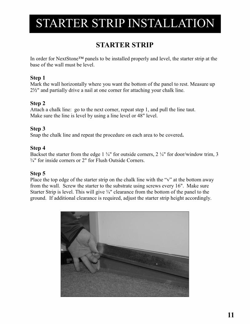
STARTER STRIP In order for NextStone™ panels to be installed properly and level, the starter strip at the
base of the wall must be level.
Step 1 Mark the wall horizontally where you want the bottom of the panel to rest. Measure up
2½" and partially drive a nail at one corner for attaching your chalk line.
Step 2 Attach a chalk line: go to the next corner, repeat step 1, and pull the line taut.
Make sure the line is level by using a line level or 48" level.
Step 3 Snap the chalk line and repeat the procedure on each area to be covered.
Step 4 Backset the starter from the edge 1 ¾" for outside corners, 2 ¼" for door/window trim, 3
¾" for inside corners or 2" for Flush Outside Corners.
Step 5 Place the top edge of the starter strip on the chalk line with the “v” at the bottom away
from the wall. Screw the starter to the substrate using screws every 16". Make sure
Starter Strip is level. This will give ¾" clearance from the bottom of the panel to the
ground. If additional clearance is required, adjust the starter strip height accordingly.
12
CORNER INSTALLATION
SANDSTONE OUTSIDE CORNERS
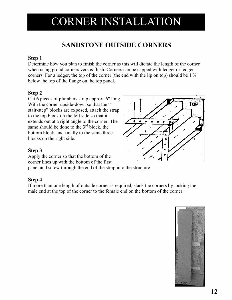
Step 1 Determine how you plan to finish the corner as this will dictate the length of the corner
when using proud corners versus flush. Corners can be capped with ledger or ledger
corners. For a ledger, the top of the corner (the end with the lip on top) should be 1 ⅜"
below the top of the flange on the top panel.
Step 2 Cut 6 pieces of plumbers strap approx. 6" long.
With the corner upside-down so that the “
stair-step” blocks are exposed, attach the strap
to the top block on the left side so that it
extends out at a right angle to the corner. The
same should be done to the 3rd block, the
bottom block, and finally to the same three
blocks on the right side.
Step 3 Apply the corner so that the bottom of the
corner lines up with the bottom of the first
panel and screw through the end of the strap into the structure.
Step 4 If more than one length of outside corner is required, stack the corners by locking the
male end at the top of the corner to the female end on the bottom of the corner.

13
SANDSTONE INSIDE CORNERS
Step 1 Determine how you plan to finish the corner as this will dictate the length of the corner.
Corners can be capped with ledger or ledger corners. For a ledger finish, the top of the
corner (the end with the lip on top) should be 1 ⅝" below the top of the flange on the top
panel.
Step 2 Locate corner so that the bottom of the corner will be flush with the bottom of the
bottom panel. Screw thru the recessed channel at the top, bottom and middle of each
side of the corner using at least a 4 ½" screw. Adhesive maybe applied to the blocks on
the back side of the corner, if appropriate for the installation.
Step 3 If more than one length of outside corner is required, stack the corners by locking the
male end at the top of the corner to the female end on the bottom of the corner.
CORNER INSTALLATION
14
CORNER INSTALLATION
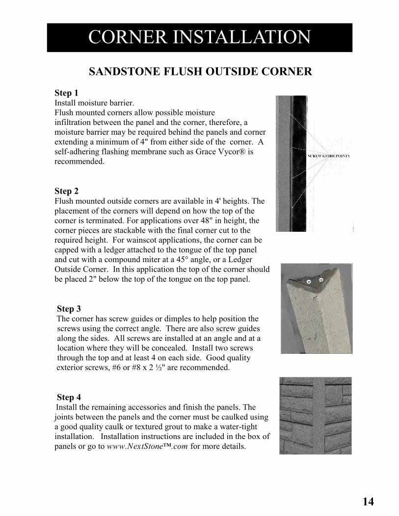
SANDSTONE FLUSH OUTSIDE CORNER
Step 1 Install moisture barrier.
Flush mounted corners allow possible moisture
infiltration between the panel and the corner, therefore, a
moisture barrier may be required behind the panels and corner
extending a minimum of 4" from either side of the corner. A
self-adhering flashing membrane such as Grace Vycor® is
recommended.
Step 2 Flush mounted outside corners are available in 4' heights. The
placement of the corners will depend on how the top of the
corner is terminated. For applications over 48" in height, the
corner pieces are stackable with the final corner cut to the
required height. For wainscot applications, the corner can be
capped with a ledger attached to the tongue of the top panel
and cut with a compound miter at a 45° angle, or a Ledger
Outside Corner. In this application the top of the corner should
be placed 2" below the top of the tongue on the top panel.
Step 3 The corner has screw guides or dimples to help position the
screws using the correct angle. There are also screw guides
along the sides. All screws are installed at an angle and at a
location where they will be concealed. Install two screws
through the top and at least 4 on each side. Good quality
exterior screws, #6 or #8 x 2 ½" are recommended.
Step 4 Install the remaining accessories and finish the panels. The
joints between the panels and the corner must be caulked using
a good quality caulk or textured grout to make a water-tight
installation. Installation instructions are included in the box of
panels or go to www.NextStone™.com for more details.
15
CORNER INSTALLATION
All products must be allowed to acclimate; removed from boxes and stored flat at the installation site for a minimum of 48 hours or until properly acclimated prior to installation. Heat and moisture cause expansion. Best results are obtained by installing a cool, dry product. NextStone™ does not warrant against gapping caused by expansion and contraction or improper installation.
CASTLE ROCK OUTSIDE CORNER
Step 1-Start the 1st course from the outside corner of the wall. Place starter strip top
2 ¾" above the desired starting height of the wall, recess the strip 2" from each side
of the corner edge.
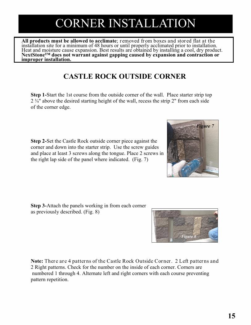
Step 2-Set the Castle Rock outside corner piece against the
corner and down into the starter strip. Use the screw guides
and place at least 3 screws along the tongue. Place 2 screws in
the right lap side of the panel where indicated. (Fig. 7)
Step 3-Attach the panels working in from each corner
as previously described. (Fig. 8)
Figure 7
Figure 8
Note: There are 4 patterns of the Castle Rock Outside Corner . 2 Left patterns and
2 Right patterns. Check for the number on the inside of each corner. Corners are
numbered 1 through 4. Alternate left and right corners with each course preventing
pattern repetition.
16
CORNER INSTALLATION
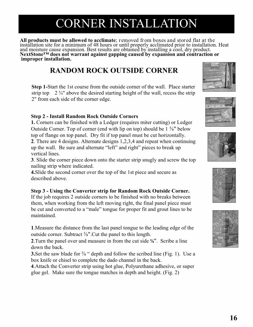
RANDOM ROCK OUTSIDE CORNER
Step 2 - Install Random Rock Outside Corners
1. Corners can be finished with a Ledger (requires miter cutting) or Ledger
Outside Corner. Top of corner (end with lip on top) should be 1 ⅜" below
top of flange on top panel. Dry fit if top panel must be cut horizontally.
2. There are 4 designs. Alternate designs 1,2,3,4 and repeat when continuing
up the wall. Be sure and alternate “left” and right” pieces to break up
vertical lines.
3. Slide the corner piece down onto the starter strip snugly and screw the top
nailing strip where indicated.
4.Slide the second corner over the top of the 1st piece and secure as
described above.
Step 3 - Using the Converter strip for Random Rock Outside Corner.
If the job requires 2 outside corners to be finished with no breaks between
them, when working from the left moving right, the final panel piece must
be cut and converted to a “male” tongue for proper fit and grout lines to be
maintained.
1.Measure the distance from the last panel tongue to the leading edge of the
outside corner. Subtract ⅜".Cut the panel to this length.
2.Turn the panel over and measure in from the cut side ⅝". Scribe a line
down the back.
3.Set the saw blade for ⅜ “ depth and follow the scribed line (Fig. 1). Use a
box knife or chisel to complete the dado channel in the back.
4.Attach the Converter strip using hot glue, Polyurethane adhesive, or super
glue gel. Make sure the tongue matches in depth and height. (Fig. 2)
All products must be allowed to acclimate; removed from boxes and stored flat at the installation site for a minimum of 48 hours or until properly acclimated prior to installation. Heat and moisture cause expansion. Best results are obtained by installing a cool, dry product. NextStone™ does not warrant against gapping caused by expansion and contraction or improper installation.
Step 1-Start the 1st course from the outside corner of the wall. Place starter
strip top 2 ¾" above the desired starting height of the wall, recess the strip
2" from each side of the corner edge.

17
RANDOM ROCK OUTSIDE CORNER, Cont. 5.After curing, fill any gaps between the panel face and converter piece with NextStone™ grout. Fill
from the back side to insure a solid grout line is achieved (Fig. 3). Use putty knife along rock edges
to achieve a smooth surface. After it becomes tacky, use touch up kit to paint the exposed edges and
grout (Fig. 4).
6.Attach the piece as if it were a full panel (Fig. 5).
If terminating the run on the right side with other trim pieces, follow the instructions below
For 2 facing Outside Corners follow Section 3 on previous page.
1 - Starting from the left, take a full panel and attach the bottom tongue into the
starter strip groove, lock in place, and slide the panel left behind the accessory
piece, see back. Using the screw guide points, screw through the substrate and
into a stud when practical, with a minimum of 6 screws per panel and a screw no
less than 1" from each end of the tongue as well as in the bottom right corner of
the tongue. Working left to right continue installing panels in the bottom course
making sure each panel is properly set in the starter strip. For the last panel in the
course, measure from the edge of the grout line to the accessory piece, add 1" If
sliding behind a trim piece, cut the last piece until the panel is locked in the
starter strip, then slide panel back to the left until the shiplap sides are joined.
(Check for level.)
2 - Install the remaining courses by beginning the course from the left with full
panels. The stagger is built in with the corner pieces. Slide the panel down
over the tongue of the first course. Install remaining panels in the course, end
row as before, and check for level. Align panels using the alignment mark at
each side on the tongue. Do not align panels using the top of the tongue. The
remaining courses are installed the same way. Stagger the NextStone™ butt
joints so that no two courses are aligned vertically unless separated by
three courses. (All exposed edges should be painted and caulked behind tr im pieces. )
3 - Cut panels around fixtures and other wall protrusions (hose bibs, electrical boxes, dryer vents, etc)
to accommodate NextStone™ Mounting Blocks. See Install instructions on page 25 or visit
NextStone™.com for details on how to cut panels and install the mounting blocks.
Figure 1 Figure 2 Figure 3 Figure 4 Figure 5

18
SLATESTONE OUTSIDE CORNER Step 1 Metal Starter Strip - Determine at what height above grade level you
want the panel to sit. Measure up 2 ¾" from this point and strike a level
line. Attach the top of the starter strip on this line. End the strip 2"
from each side of the corner.
Step 2 Set the Slatestone outside corner piece against the corner and down
into the starter strip. Use the screw guides and place at least 3
screws along the tongue. Place 2 screws in the right lap side of the
panel where indicated.
Step 3 Attach the panels working out from each side of the corner as
previously described.
Note: There are 4 patterns of the Slatestone Outside Corner.
2 Left patterns and 2 right patterns. Check for numbers on the
backside of the piece. They are numbered 1 through 4. Alternate
left and right corners with each course to prevent pattern repetition.
CORNER INSTALLATION
All products must be allowed to acclimate; removed from boxes and stored flat at the installation site for a minimum of 48 hours or until properly acclimated prior to installation. Heat and moisture cause expansion. Best results are obtained by installing a cool, dry product. NextStone™ does not warrant against gapping caused by expansion and contraction or improper installation.
19
CORNER INSTALLATION
All products must be allowed to acclimate; removed from boxes and stored flat at the installation site for a minimum of 48 hours or until properly acclimated prior to installation. Heat and moisture cause expansion. Best results are obtained by installing a cool, dry product. NextStone™ does not warrant against gapping caused by expansion and contraction or improper installation.
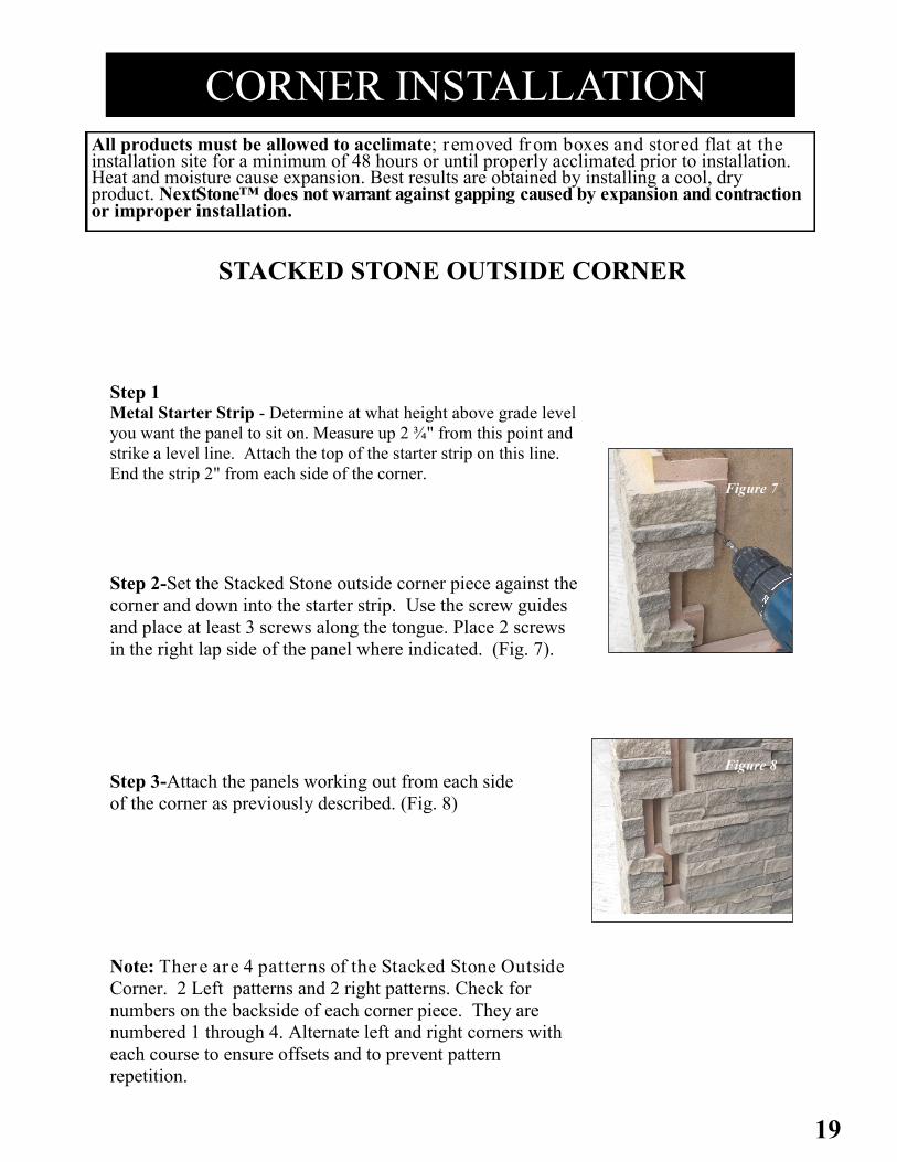
Step 1 Metal Starter Strip - Determine at what height above grade level
you want the panel to sit on. Measure up 2 ¾" from this point and
strike a level line. Attach the top of the starter strip on this line.
End the strip 2" from each side of the corner.
Step 2-Set the Stacked Stone outside corner piece against the
corner and down into the starter strip. Use the screw guides
and place at least 3 screws along the tongue. Place 2 screws
in the right lap side of the panel where indicated. (Fig. 7).
Figure 7
Step 3-Attach the panels working out from each side
of the corner as previously described. (Fig. 8)
Figure 8
Note: There are 4 patterns of the Stacked Stone Outside
Corner. 2 Left patterns and 2 right patterns. Check for
numbers on the backside of each corner piece. They are
numbered 1 through 4. Alternate left and right corners with
each course to ensure offsets and to prevent pattern
repetition.
STACKED STONE OUTSIDE CORNER
20
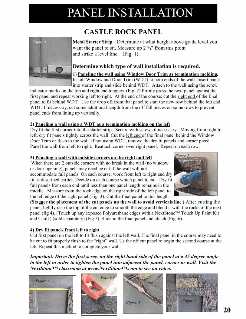
PANEL INSTALLATION
Metal Starter Strip - Determine at what height above grade level you
want the panel to sit. Measure up 2 ¾" from this point
and strike a level line. (Fig. 1)
Determine which type of wall installation is required.
1) Paneling the wall using Window Door Trim as termination molding.
Install Window and Door Trim (WDT) to both ends of the wall. Insert panel
into starter strip and slide behind WDT. Attach to the wall using the screw
indicator marks on the top and right end tongues. (Fig. 2) Firmly press the next panel against the
first panel and repeat working left to right. At the end of the course; cut the right end of the final
panel to fit behind WDT. Use the drop off from that panel to start the new row behind the left end
WDT. If necessary, cut some additional length from the off fall pieces on some rows to prevent
panel ends from lining up vertically.
2) Paneling a wall using a WDT as a termination molding on the left
Dry fit the first corner into the starter strip. Secure with screws if necessary. Moving from right to
left: dry fit panels tightly across the wall. Cut the left end of the final panel behind the Window
Door Trim or flush to the wall. If not using WDT, remove the dry fit panels and corner piece.
Panel the wall from left to right. Reattach corner over right panel. Repeat on each row.
3) Paneling a wall with outside corners on the right and left
When there are 2 outside corners with no break in the wall (no window
or door opening), panels may need be cut if the wall will not
accommodate full panels. On each course, work from left to right and dry
fit as described earlier. Decide on each course which panel to cut. Dry fit
full panels from each end until less than one panel length remains in the
middle. Measure from the rock edge on the right side of the left panel to
the left edge of the right panel (Fig. 3). Cut the final panel to this length.
(Stagger the placement of the cut panels up the wall to avoid verticals line.) After cutting the
panel, lightly rasp the top of the cut edge to smooth the edge and blend it with the rocks of the next
panel (fig 4). (Touch up any exposed Polyurethane edges with a NextStone™ Touch Up Paint Kit
and Caulk) (sold separately) (Fig 5). Slide in the final panel and attach (Fig. 6).
4) Dry fit panels from left to right Cut first panel on the left to fit flush against the left wall. The final panel in the course may need to
be cut to fit properly flush to the “right” wall. Us the off cut panel to begin the second course at the
left. Repeat this method to complete your wall.
Important: Drive the first screw on the right hand side of the panel at a 45 degree angle
to the left in order to tighten the panel into adjacent the panel, corner or wall. Visit the
NextStone™ classroom at www.NextStone™.com to see on video.
CASTLE ROCK PANEL
Figure 1
Figure 4 Figure 3
Figure 6
Figure 2
Figure 5
21
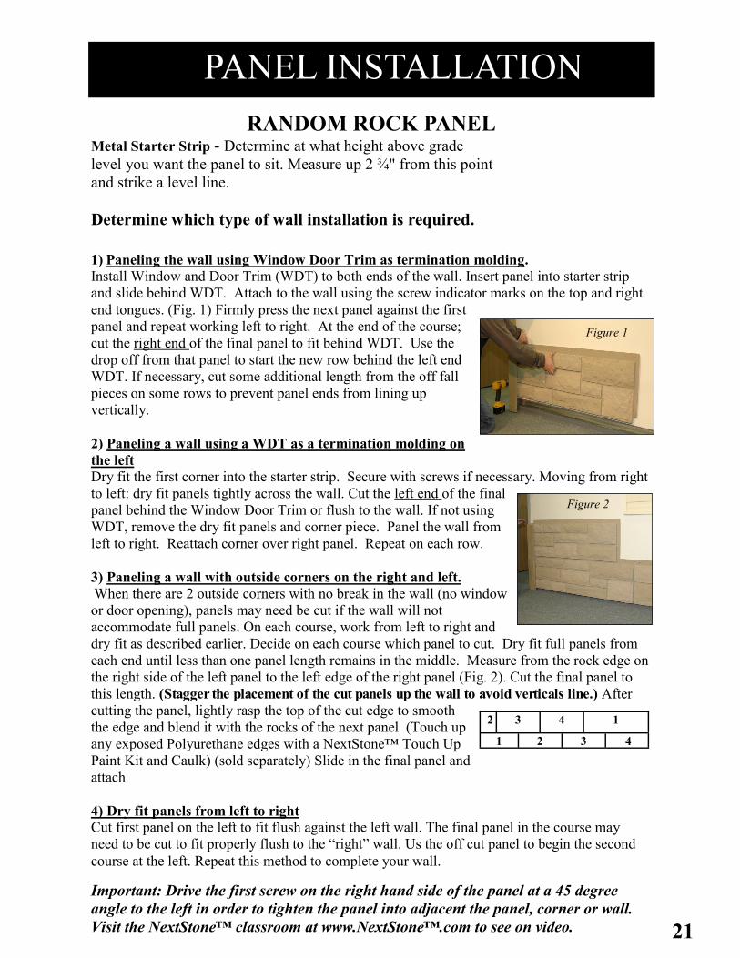
RANDOM ROCK PANEL
Metal Starter Strip - Determine at what height above grade
level you want the panel to sit. Measure up 2 ¾" from this point
and strike a level line.
Determine which type of wall installation is required.
1) Paneling the wall using Window Door Trim as termination molding.
Install Window and Door Trim (WDT) to both ends of the wall. Insert panel into starter strip
and slide behind WDT. Attach to the wall using the screw indicator marks on the top and right
end tongues. (Fig. 1) Firmly press the next panel against the first
panel and repeat working left to right. At the end of the course;
cut the right end of the final panel to fit behind WDT. Use the
drop off from that panel to start the new row behind the left end
WDT. If necessary, cut some additional length from the off fall
pieces on some rows to prevent panel ends from lining up
vertically.
2) Paneling a wall using a WDT as a termination molding on
the left
Dry fit the first corner into the starter strip. Secure with screws if necessary. Moving from right
to left: dry fit panels tightly across the wall. Cut the left end of the final
panel behind the Window Door Trim or flush to the wall. If not using
WDT, remove the dry fit panels and corner piece. Panel the wall from
left to right. Reattach corner over right panel. Repeat on each row.
3) Paneling a wall with outside corners on the right and left.
When there are 2 outside corners with no break in the wall (no window
or door opening), panels may need be cut if the wall will not
accommodate full panels. On each course, work from left to right and
dry fit as described earlier. Decide on each course which panel to cut. Dry fit full panels from
each end until less than one panel length remains in the middle. Measure from the rock edge on
the right side of the left panel to the left edge of the right panel (Fig. 2). Cut the final panel to
this length. (Stagger the placement of the cut panels up the wall to avoid verticals line.) After
cutting the panel, lightly rasp the top of the cut edge to smooth
the edge and blend it with the rocks of the next panel (Touch up
any exposed Polyurethane edges with a NextStone™ Touch Up
Paint Kit and Caulk) (sold separately) Slide in the final panel and
attach
4) Dry fit panels from left to right Cut first panel on the left to fit flush against the left wall. The final panel in the course may
need to be cut to fit properly flush to the “right” wall. Us the off cut panel to begin the second
course at the left. Repeat this method to complete your wall.
Important: Drive the first screw on the right hand side of the panel at a 45 degree
angle to the left in order to tighten the panel into adjacent the panel, corner or wall.
Visit the NextStone™ classroom at www.NextStone™.com to see on video.
PANEL INSTALLATION
2 3 4 1
1 2 3 4
Figure 1
Figure 2

22
PANEL INSTALLATION
SLATESTONE PANEL
Metal Starter Strip - Determine at what height above grade level you want the panel to
sit. Measure up 2 ¾" from this point and strike a level line. (Fig. 1)
Determine which type of wall installation is required.
1) Paneling the wall using Window Door Trim as termination
molding.
Install Window and Door Trim (WDT) to both ends of the wall.
Insert panel into starter strip and slide behind WDT. Attach to the
wall using the screw indicator marks on the top and right end
tongues. (Fig. 2) Firmly press the next panel against the first panel
and repeat working left to right. At the end of the course; cut the
right end of the final panel to fit behind WDT. Use the drop off
from that panel to start the new row behind the left end WDT. If
necessary, cut some additional length from the off fall pieces on
some rows to prevent panel ends from lining up vertically.
2) Paneling a wall using a WDT as a termination molding on the left
Dry fit the first corner into the starter strip. Secure with screws if necessary. Moving from right
to left: dry fit panels tightly across the wall. Cut the left end of the final panel behind the
Window Door Trim or flush to the wall. If not using WDT, remove the dry fit panels and corner
piece. Panel the wall from left to right. Reattach corner over right panel. Repeat on each row.
3) Paneling a wall with outside corners on the right and left
Dry fit Slatestone Corners on the left and right. Secure panels moving towards the
center from both directions. Cut a panel to meet the remaining measurement. Finger
joints on either the left panel or the right panel will need to be cut to accommodate the
final cut piece. Secure the cut piece into the allotted space and screw in to secure all
panels. Using the fall off of cut panel, secure the finger joints on the end to other left or
right corner and begin the next course as described above. (Fig. 2)
*Finger joints can be cut on both panels (See figure 6 on
page 24) to accommodate a cut piece.
4) Dry fit panels from left to right Cut first panel on the left to fit flush against the left wall. The
final panel in the course may need to be cut to fit properly flush
to the “right” wall. Us the off cut panel to begin the second
course at the left. Repeat this method to complete your wall.
Important: Drive the first screw on the right hand side of
the panel at a 45 degree angle to the left in order to
tighten the panel into adjacent the panel, corner or wall.
Visit the NextStone™ classroom at
Figure 1
Figure 2
23
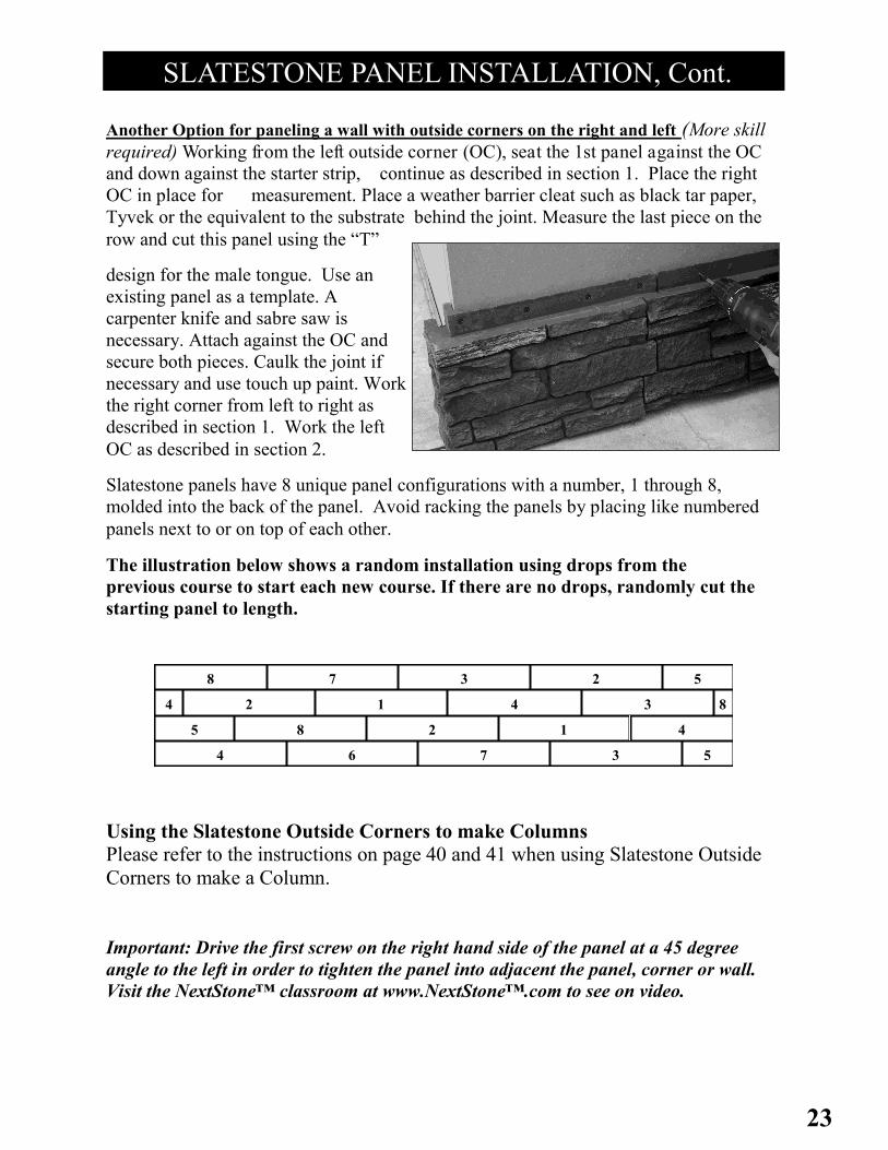
SLATESTONE PANEL INSTALLATION, Cont.
Another Option for paneling a wall with outside corners on the right and left (More skill
required) Working from the left outside corner (OC), seat the 1st panel against the OC
and down against the starter strip, continue as described in section 1. Place the right
OC in place for measurement. Place a weather barrier cleat such as black tar paper,
Tyvek or the equivalent to the substrate behind the joint. Measure the last piece on the
row and cut this panel using the “T”
design for the male tongue. Use an
existing panel as a template. A
carpenter knife and sabre saw is
necessary. Attach against the OC and
secure both pieces. Caulk the joint if
necessary and use touch up paint. Work
the right corner from left to right as
described in section 1. Work the left
OC as described in section 2.
Slatestone panels have 8 unique panel configurations with a number, 1 through 8,
molded into the back of the panel. Avoid racking the panels by placing like numbered
panels next to or on top of each other.
The illustration below shows a random installation using drops from the
previous course to start each new course. If there are no drops, randomly cut the
starting panel to length.
Using the Slatestone Outside Corners to make Columns
Please refer to the instructions on page 40 and 41 when using Slatestone Outside
Corners to make a Column.
Important: Drive the first screw on the right hand side of the panel at a 45 degree
angle to the left in order to tighten the panel into adjacent the panel, corner or wall.
Visit the NextStone™ classroom at www.NextStone™.com to see on video.
4
4 6 7 3 5
5 8 2 1
4 2 1 4 3 8
8 7 3 2 5
24
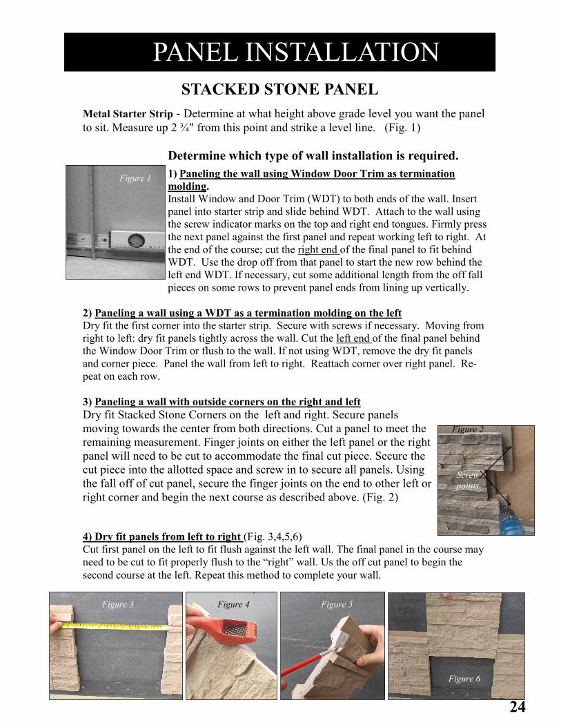
PANEL INSTALLATION
STACKED STONE PANEL
Metal Starter Strip - Determine at what height above grade level you want the panel
to sit. Measure up 2 ¾" from this point and strike a level line. (Fig. 1)
Determine which type of wall installation is required.
1) Paneling the wall using Window Door Trim as termination
molding.
Install Window and Door Trim (WDT) to both ends of the wall. Insert
panel into starter strip and slide behind WDT. Attach to the wall using
the screw indicator marks on the top and right end tongues. Firmly press
the next panel against the first panel and repeat working left to right. At
the end of the course; cut the right end of the final panel to fit behind
WDT. Use the drop off from that panel to start the new row behind the
left end WDT. If necessary, cut some additional length from the off fall
pieces on some rows to prevent panel ends from lining up vertically.
2) Paneling a wall using a WDT as a termination molding on the left
Dry fit the first corner into the starter strip. Secure with screws if necessary. Moving from
right to left: dry fit panels tightly across the wall. Cut the left end of the final panel behind
the Window Door Trim or flush to the wall. If not using WDT, remove the dry fit panels
and corner piece. Panel the wall from left to right. Reattach corner over right panel. Re-
peat on each row.
3) Paneling a wall with outside corners on the right and left
Dry fit Stacked Stone Corners on the left and right. Secure panels
moving towards the center from both directions. Cut a panel to meet the
remaining measurement. Finger joints on either the left panel or the right
panel will need to be cut to accommodate the final cut piece. Secure the
cut piece into the allotted space and screw in to secure all panels. Using
the fall off of cut panel, secure the finger joints on the end to other left or
right corner and begin the next course as described above. (Fig. 2)
4) Dry fit panels from left to right (Fig. 3,4,5,6) Cut first panel on the left to fit flush against the left wall. The final panel in the course may
need to be cut to fit properly flush to the “right” wall. Us the off cut panel to begin the
second course at the left. Repeat this method to complete your wall.
Screw
points
Figure 2
Figure 1
Figure 3 Figure 4 Figure 5
Figure 6
Figure 1
25
ACCENT ROCKS (for Random Rock Panels only)
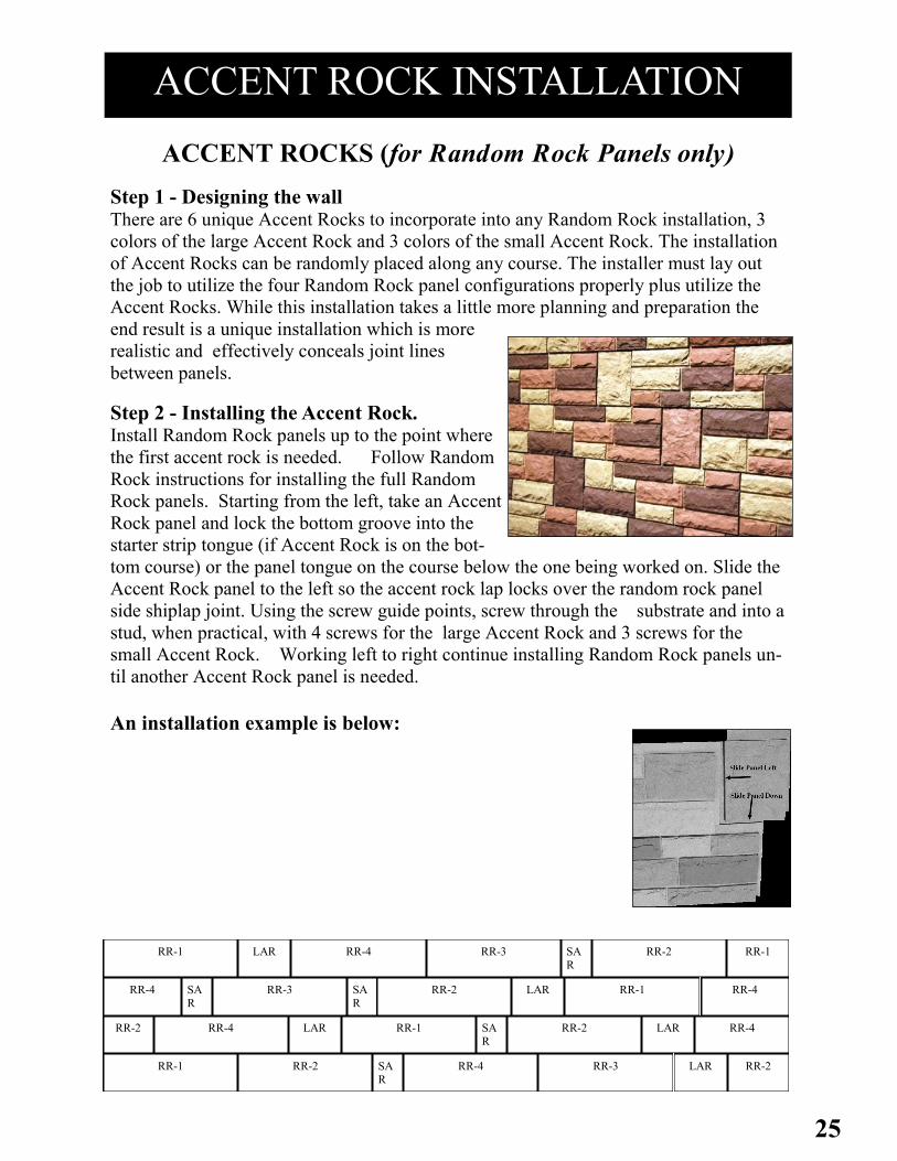
Step 1 - Designing the wall There are 6 unique Accent Rocks to incorporate into any Random Rock installation, 3
colors of the large Accent Rock and 3 colors of the small Accent Rock. The installation
of Accent Rocks can be randomly placed along any course. The installer must lay out
the job to utilize the four Random Rock panel configurations properly plus utilize the
Accent Rocks. While this installation takes a little more planning and preparation the
end result is a unique installation which is more
realistic and effectively conceals joint lines
between panels.
Step 2 - Installing the Accent Rock. Install Random Rock panels up to the point where
the first accent rock is needed. Follow Random
Rock instructions for installing the full Random
Rock panels. Starting from the left, take an Accent
Rock panel and lock the bottom groove into the
starter strip tongue (if Accent Rock is on the bot-
tom course) or the panel tongue on the course below the one being worked on. Slide the
Accent Rock panel to the left so the accent rock lap locks over the random rock panel
side shiplap joint. Using the screw guide points, screw through the substrate and into a
stud, when practical, with 4 screws for the large Accent Rock and 3 screws for the
small Accent Rock. Working left to right continue installing Random Rock panels un-
til another Accent Rock panel is needed.
An installation example is below:
ACCENT ROCK INSTALLATION
SAR
LAR RR-1 RR-4 RR-3 SAR
RR-2 RR-1
RR-4 SAR
RR-3 RR-2 LAR RR-1 SAR
RR-4
RR-2 RR-1 RR-4 LAR RR-2 RR-4 LAR
RR-1 RR-2 SAR
RR-4 RR-3 LAR RR-2

26
SANDSTONE WINDOW AND DOOR TRIM Step 1 Sandstone Window and Door Trim can be used as a utility
trim to terminate sections of NextStone™ panels, as a cap,
or as a trim piece around windows and doors. For most
applications, Sandstone Window and Door Trim must be
installed prior to the panels.
Step 2 Measure the total height of the wall before the Ledger
attachment to determine quantity and length/height of the
Window and Door Trim.
Step 3 Use a level when placing Window and Door Trim. Install
with dado away from the frame. Screw at a 45° angle
through the top of the piece and down along the inside
edge, making sure to attach securely to the underlying
substrate. To miter for use with ledger, cut the top of the
piece on a 15°angle, with the long side of the angle against
the wall.
Step 4 If desired, a wood rasp can be used to round edges of the door/window trim to provide a
more realistic look. Touch-up paint can be applied to the area formed with the rasp.
Always use a finished end to start and terminate a section of door window trim. Cut
ends can be butted tight and concealed with touch-up paint and caulk. End Ledger with a
factory finished end. (See ledger installation).
TRIM INSTALLATION All products must be allowed to acclimate; removed from boxes and stored flat at the installation site for a minimum of 48 hours or until properly acclimated prior to installation. Heat and moisture cause expansion. Best results are obtained by installing cool, dry product. NextStone™ does not warrant against gapping caused by expansion and contraction.
Window and Door
Trim under the Ledger
27
TRIM INSTALLATION
SANDSTONE LEDGER
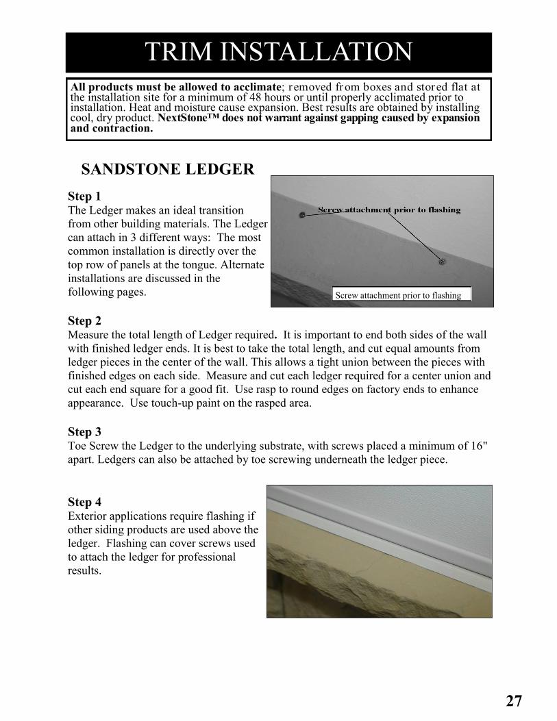
Step 1 The Ledger makes an ideal transition
from other building materials. The Ledger
can attach in 3 different ways: The most
common installation is directly over the
top row of panels at the tongue. Alternate
installations are discussed in the
following pages.
Step 2 Measure the total length of Ledger required. It is important to end both sides of the wall
with finished ledger ends. It is best to take the total length, and cut equal amounts from
ledger pieces in the center of the wall. This allows a tight union between the pieces with
finished edges on each side. Measure and cut each ledger required for a center union and
cut each end square for a good fit. Use rasp to round edges on factory ends to enhance
appearance. Use touch-up paint on the rasped area.
Step 3 Toe Screw the Ledger to the underlying substrate, with screws placed a minimum of 16"
apart. Ledgers can also be attached by toe screwing underneath the ledger piece.
Step 4 Exterior applications require flashing if
other siding products are used above the
ledger. Flashing can cover screws used
to attach the ledger for professional
results.
Screw attachment prior to flashing
All products must be allowed to acclimate; removed from boxes and stored flat at the installation site for a minimum of 48 hours or until properly acclimated prior to installation. Heat and moisture cause expansion. Best results are obtained by installing cool, dry product. NextStone™ does not warrant against gapping caused by expansion and contraction.

28
LEDGER INSTALLATION, Cont.
Step 5 If the ledger is used to go over the top of outside or inside corner
accessories a compound miter is required. (Ledger Inside and Outside
Corners can be used and do not require mitering). This can be achieved
using a chop saw or radial arm saw. Place the ledger on the saw table
with the back of the ledger flush against the fence (just the way it sits
when applied), and make a 45° miter cut. The corner will then require
caulking and NextStone™ touch-up paint.
INSTALL LEDGER ON CUT PANEL (ALTERNATE
INSTALLATION METHOD) If the top panel must be cut horizontally and the tongue is
removed, the ledger is installed using the flat portion on the
bottom of the ledger. The ledger is then glued to the wall behind it
and screwed using the methods described above. To avoid cutting
panels at the top, cut at the base of the panel and “face screw” into
Substrate. Starter strip would not be necessary.
SANDSTONE LEDGER OUTSIDE AND INSIDE
CORNERS
Outside and Inside Ledger Corners can be used for a faster, miter free installation.
Theses pieces are molded for 90˚ angles.
Simply place the Ledger Inside or Outside Corner over the top of the corner, using the
“v” groove. If the corners have been cut for height, use the bottom surface of the Ledger
Corner.
¼" Bead
Adhesive:
= Full Panel
= Cut Panel

29
INSTALL LEDGER USING MOUNTING BLOCKS
(ALTERNATE INSTALLATION METHOD)
Ledgers can be installed using mounting blocks for a totally concealed fastening
system. This installation method is primarily recommended for installations below a
casement.
On the back side of the ledger below the tongue are three pockets. These pockets are
made to accommodate wood blocks made from standard 1 x 6 nominal material cut
1 ½" long. Viewing the ledger from the front, the centerlines of the pockets are 8 5/16"
from the right end, 21 ⅞" from the right end, and 35 ⅜" from the right end respectively.
Dry fit ledger and mark location of the top and right end of the ledger. Blocks should be
fastened to the wall and located to align with the pockets. The top of the blocks should
be ¾" below the top of the ledger. The ledger is then placed on the panel as with the
previously described methods.
After placing the ledger onto the mounting blocks, drive a screw from the bottom of the
ledger into the mounting blocks. Adhesive should be applied to the blocks and to the
ledger using the method illustrated on the previous page.
LEDGER INSTALLATION Cont.
All products must be allowed to acclimate; removed from boxes and stored flat at the installation site for a minimum of 48 hours or until properly acclimated prior to installation. Heat and moisture cause expansion. Best results are obtained by installing cool, dry product. NextStone™ does not warrant against gapping caused by expansion and contraction.

30
TRIM INSTALLATION
MOUNTING BLOCKS Step 1 Locate the center of the object to be attached to the mounting block
(outlet box, hose bib, electrical box, etc.). Then locate where the edge of
the panel to be cut out will fall on the panel to the left and mark. Measure
from the center of the object to the mark locating bottom of the panel and
measure to the mark locating where the left edge of the panel will fall.
Step 2 Transfer these measurements to the back of the panel being cut out
and mark. This mark should correspond with the center of the object
installed. Using this mark as center draw a rectangle 7 ½" x 10 ½"
for the large mounting block or 5" x 6" for the small mounting
block. Mounting blocks can be installed horizontally or vertically.
Step 3 Using the rectangle you drew on the back of the panel as a cutting guide,
cutout the panel. Install the cutout panel in the standard fashion.
Step 4 On the back side of the mounting block you will see a pre-formed area
molded into the block. On the large mounting block it is a round area for round outlet
boxes. On the small mounting block are the pre-formed areas for
plumbing rough-ins, single and double outlet boxes, and round fixture
cutouts.
Step 5 Determine which cut out and what size is appropriate. Drill a hole on the side of the cut
out area to use as a starter hole. Cut the pattern on the block using a saber saw. Always
cut from the back of the mounting block to avoid marring the front surface of the
mounting block. If necessary, use a wood rasp to fine tune the cutout.
Step 6 Apply caulk and/or adhesive to the back of the mounting block to seal
between the mounting block and the panel. Put the mounting block in place
and attach with 3" screws. Place screws where they will be concealed by
the cover plate of the fixture, if possible.
Step 7 Attach electrical boxes to the face of the cover plate as applicable. Install
the fixture and it’s cover plate. Caulk around fixture as necessary.
31
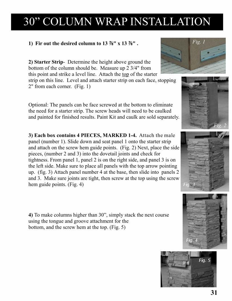
1) Fir out the desired column to 13 ⅞" x 13 ⅞" .
2) Starter Strip- Determine the height above ground the
bottom of the column should be. Measure up 2 3/4" from
this point and strike a level line. Attach the top of the starter
strip on this line. Level and attach starter strip on each face, stopping
2" from each corner. (Fig. 1)
Optional: The panels can be face screwed at the bottom to eliminate
the need for a starter strip. The screw heads will need to be caulked
and painted for finished results. Paint Kit and caulk are sold separately.
3) Each box contains 4 PIECES, MARKED 1-4. Attach the male
panel (number 1). Slide down and seat panel 1 onto the starter strip
and attach on the screw hem guide points. (Fig. 2) Next, place the side
pieces, (number 2 and 3) into the dovetail joints and check for
tightness. From panel 1, panel 2 is on the right side, and panel 3 is on
the left side. Make sure to place all panels with the top arrow pointing
up. (fig. 3) Attach panel number 4 at the base, then slide into panels 2
and 3. Make sure joints are tight, then screw at the top using the screw
hem guide points. (Fig. 4)
4) To make columns higher than 30”, simply stack the next course
using the tongue and groove attachment for the
bottom, and the screw hem at the top. (Fig. 5)
30” COLUMN WRAP INSTALLATION
Fig. 1
Fig. 2
Fig. 2

32
30" COLUMN WRAP, Cont.
Top Course with Screw Hem Attached
Adhesive
Points
Bottom of Cap Fig. 1
Top Course with Screw Hem Removed Bottom of Cap fig. 2
Adhesive
Points
The Sandstone 18" Column Wrap Cap is designed to fit the Slatestone Col-
umn with or without the screw hems.
Screw Attachment: Drive one screw per side through the bottom lip of the
cap all the way into the substrate. Be Careful to angle the Screws so they don’t
run through the top of the cap. Do not overdrive screws.
Adhesive Attachments:
1) If the top course ends with the screw hem attached: Place adhesive in each
corner of the cap and secure. (Fig. 1).
2) If the top course of corners has the screw hems cut off, face screw each piece
1” from the top so that the cap covers the screw heads. Place adhesive on inside
cutouts as shown (Fig. 2).
33
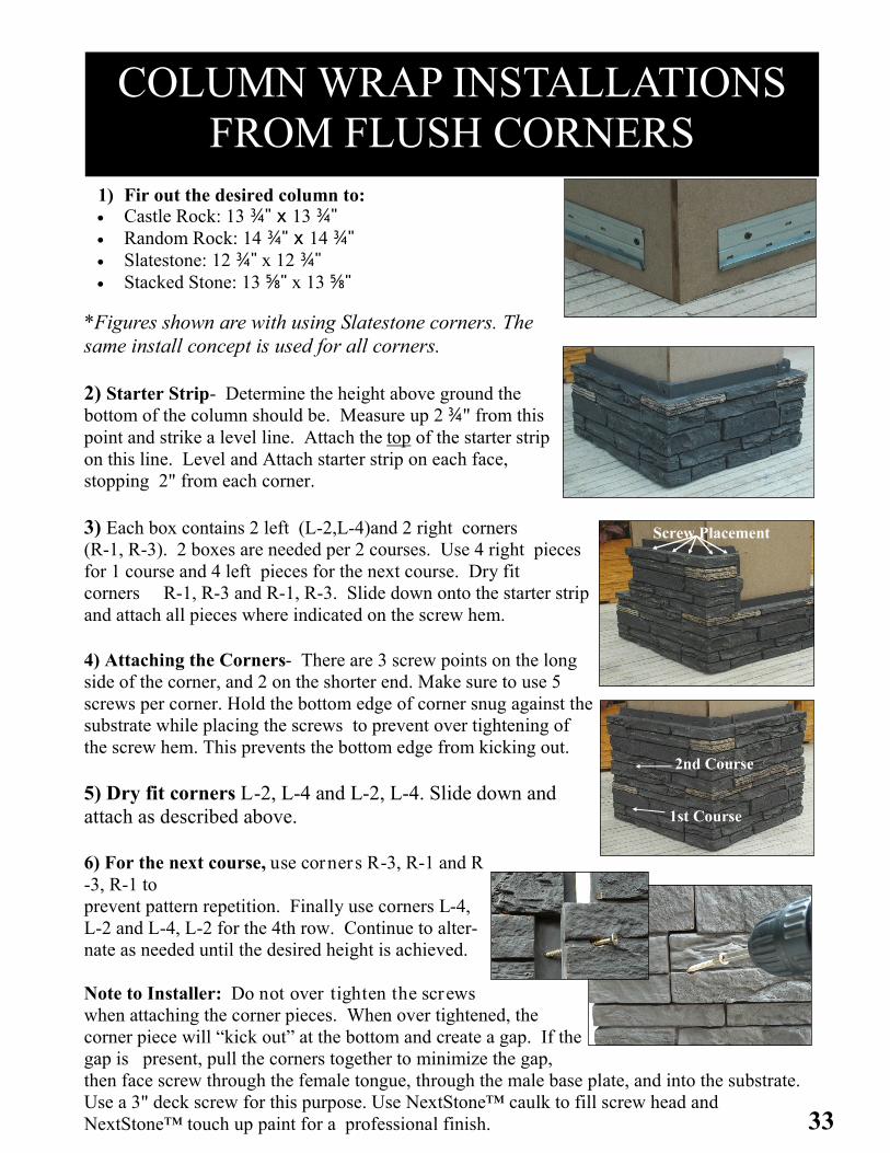
*Figures shown are with using Slatestone corners. The
same install concept is used for all corners.
2) Starter Strip- Determine the height above ground the
bottom of the column should be. Measure up 2 ¾" from this
point and strike a level line. Attach the top of the starter strip
on this line. Level and Attach starter strip on each face,
stopping 2" from each corner.
3) Each box contains 2 left (L-2,L-4)and 2 right corners
(R-1, R-3). 2 boxes are needed per 2 courses. Use 4 right pieces
for 1 course and 4 left pieces for the next course. Dry fit
corners R-1, R-3 and R-1, R-3. Slide down onto the starter strip
and attach all pieces where indicated on the screw hem.
4) Attaching the Corners- There are 3 screw points on the long
side of the corner, and 2 on the shorter end. Make sure to use 5
screws per corner. Hold the bottom edge of corner snug against the
substrate while placing the screws to prevent over tightening of
the screw hem. This prevents the bottom edge from kicking out.
5) Dry fit corners L-2, L-4 and L-2, L-4. Slide down and
attach as described above.
6) For the next course, use corners R-3, R-1 and R
-3, R-1 to
prevent pattern repetition. Finally use corners L-4,
L-2 and L-4, L-2 for the 4th row. Continue to alter-
nate as needed until the desired height is achieved.
Note to Installer: Do not over tighten the screws
when attaching the corner pieces. When over tightened, the
corner piece will “kick out” at the bottom and create a gap. If the
gap is present, pull the corners together to minimize the gap,
then face screw through the female tongue, through the male base plate, and into the substrate.
Use a 3" deck screw for this purpose. Use NextStone™ caulk to fill screw head and
NextStone™ touch up paint for a professional finish.
Screw Placement
2nd Course
1st Course
COLUMN WRAP INSTALLATIONS
FROM FLUSH CORNERS
1) Fir out the desired column to: Castle Rock: 13 ¾" x 13 ¾" Random Rock: 14 ¾" x 14 ¾" Slatestone: 12 ¾" x 12 ¾" Stacked Stone: 13 ⅝" x 13 ⅝"

34
COLUMN WRAPS FROM FLUSH CORNERS, Cont.
The Sandstone 18" Column Wrap cap is designed to fit over the columns if
the top course of corners ends with the screw hems attached or with the
screw hems removed.
Screw Attachment: Drive one scr ew per side through the bottom lip of the cap all
the way into the substrate. Be Careful to angle the Screws so they don’t run through the
top of the cap.
Do not overdrive screws.
Adhesive Attachments: 1) If the top course ends with the screw hem attached:
Place adhesive in each corner of the cap and secure. (Fig. 1).
2) If the top course of corners has the screw hems cut off, face screw each piece
1" from the top so that the cap covers the screw heads. Place adhesive on inside
cutouts as shown (Fig. 2).
Top Course with Screw Hem Attached
Adhesive
Points
Bottom of Cap
Top Course with Screw Hem Removed
Adhesive
Points
Bottom of Cap
35
SLATESTONE 1PC POST COVER INSTALL
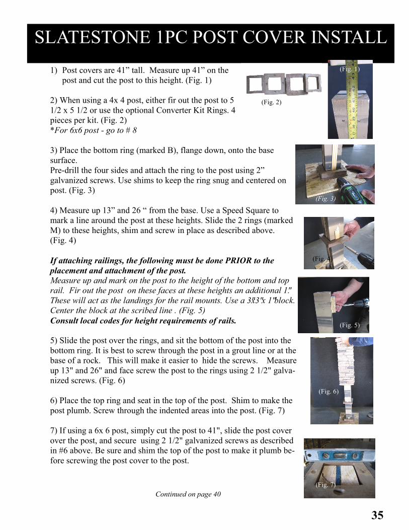
1) Post covers are 41” tall. Measure up 41” on the
post and cut the post to this height. (Fig. 1)
2) When using a 4x 4 post, either fir out the post to 5
1/2 x 5 1/2 or use the optional Converter Kit Rings. 4
pieces per kit. (Fig. 2)
*For 6x6 post - go to # 8
3) Place the bottom ring (marked B), flange down, onto the base
surface.
Pre-drill the four sides and attach the ring to the post using 2”
galvanized screws. Use shims to keep the ring snug and centered on
post. (Fig. 3)
4) Measure up 13” and 26 “ from the base. Use a Speed Square to
mark a line around the post at these heights. Slide the 2 rings (marked
M) to these heights, shim and screw in place as described above.
(Fig. 4)
If attaching railings, the following must be done PRIOR to the
placement and attachment of the post.
Measure up and mark on the post to the height of the bottom and top
rail. Fir out the post on these faces at these heights an additional 1".
These will act as the landings for the rail mounts. Use a 3"x3" x 1" block.
Center the block at the scribed line . (Fig. 5)
Consult local codes for height requirements of rails.
5) Slide the post over the rings, and sit the bottom of the post into the
bottom ring. It is best to screw through the post in a grout line or at the
base of a rock. This will make it easier to hide the screws. Measure
up 13" and 26" and face screw the post to the rings using 2 1/2" galva-
nized screws. (Fig. 6)
6) Place the top ring and seat in the top of the post. Shim to make the
post plumb. Screw through the indented areas into the post. (Fig. 7)
7) If using a 6x 6 post, simply cut the post to 41", slide the post cover
over the post, and secure using 2 1/2" galvanized screws as described
in #6 above. Be sure and shim the top of the post to make it plumb be-
fore screwing the post cover to the post.
(Fig. 2)
(Fig. 1)
(Fig. 3)
(Fig. 4)
(Fig. 5)
(Fig. 6)
(Fig. 7)
Continued on page 40

36
SLATESTONE 2PC POST COVER INSTALL
1) Post covers are 41” tall. Measure up 41” on the post. Cut the post to
this height. (Fig. 1)
2) When using a 4 x 4 post, either fir out the post to
5 ½ x 5 ½ or use the optional Converter Kit Rings.
4 pieces per kit.
(Fig. 2)
3) Place the bottom ring (marked B), flange down, onto the deck.
Predrilled the four sides and attach the ring to the post using 2” galva-
nized screws. Use shims to make the ring snug and centered on post.
(Fig. 3)
4) Measure up 13 ½” and 27 ½ “ from the deck. Use a Speed
Square to mark a line around the post at these heights. Slide the
2 rings (marked M) so the bottom of the ring is on these lines,
shim and screw in place as described above. (Fig. 4)
If attaching railings, the following must be done PRIOR to the
placement and attachment of the post.
Measure up and mark on the post to the height of the bottom and
top rail. Fir out the post on these faces at these heights an additional 1".
These will act as the landings for the rail mounts. Use a 3"x3" x1" block.
Center the block at the scribed line . ( Fig. 5)
Consult local codes for height requirements of rails.
5) Position Side 1, with the arrow facing up. Seat the bottom of the post
into the bottom ring. Face screw the post cover through the rings and into the
wood post using 3" galvanized screws. Screw through the post in a grout
line or at the base of a rock. This will make it easier to hide the screws.
Measure up 14" and 28" and face screw through the posts and into the rings.
The posts are designed with a grout line at these heights. (Fig. 6)
6) Place the top ring and seat into the top of the post. Shim to make the
post plumb. Screw through the indented areas into the post. (Fig. 7)
7) After securing Side 1 in place, move Side 2 into place.
Make sure the arrow is facing up.
Dry fit the piece to make sure all “T” joints line
up and are tight.
Secure side 2 at the ring heights described above.
(Fig. 2)
(Fig. 1)
(Fig. 3)
(Fig. 4)
(Fig. 5)
(Fig. 6)
(Fig. 8)
(Fig. 7)
37
SLATESTONE 1 & 2 PC POST COVER, Cont.
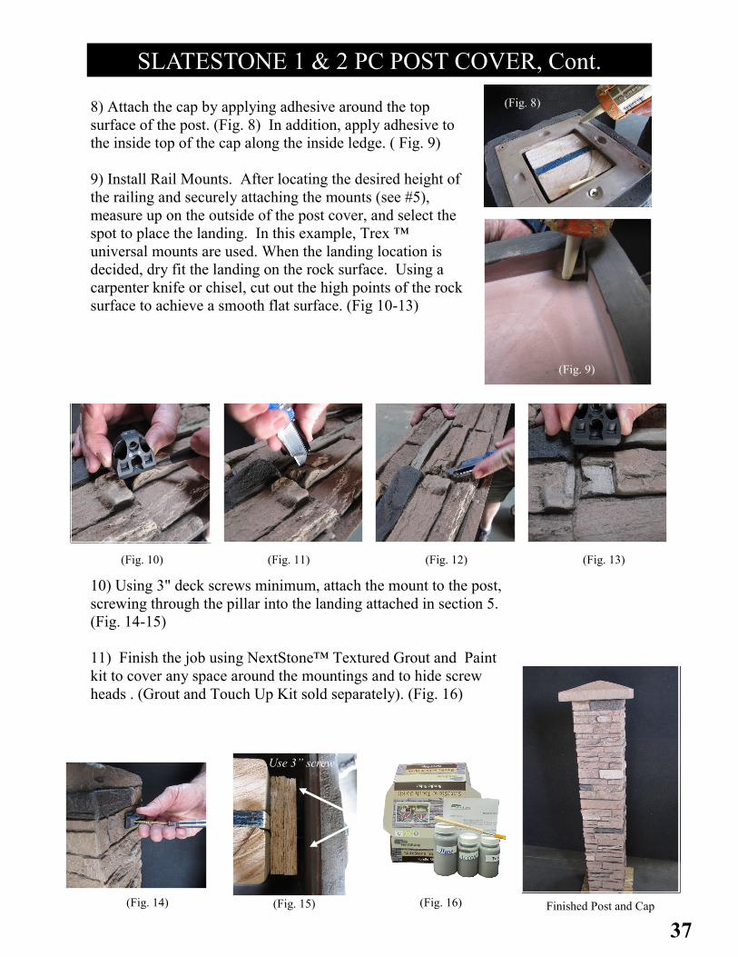
8) Attach the cap by applying adhesive around the top
surface of the post. (Fig. 8) In addition, apply adhesive to
the inside top of the cap along the inside ledge. ( Fig. 9)
9) Install Rail Mounts. After locating the desired height of
the railing and securely attaching the mounts (see #5),
measure up on the outside of the post cover, and select the
spot to place the landing. In this example, Trex ™
universal mounts are used. When the landing location is
decided, dry fit the landing on the rock surface. Using a
carpenter knife or chisel, cut out the high points of the rock
surface to achieve a smooth flat surface. (Fig 10-13)
Use 3” screw
10) Using 3" deck screws minimum, attach the mount to the post,
screwing through the pillar into the landing attached in section 5.
(Fig. 14-15)
11) Finish the job using NextStone™ Textured Grout and Paint
kit to cover any space around the mountings and to hide screw
heads . (Grout and Touch Up Kit sold separately). (Fig. 16)
Finished Post and Cap (Fig. 16) (Fig. 15) (Fig. 14)
(Fig. 13) (Fig. 12) (Fig. 11) (Fig. 10)
(Fig. 9)
(Fig. 8)
38
MITERED CORNER
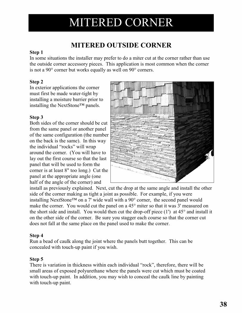
MITERED OUTSIDE CORNER Step 1
In some situations the installer may prefer to do a miter cut at the corner rather than use
the outside corner accessory pieces. This application is most common when the corner
is not a 90° corner but works equally as well on 90° corners.
Step 2
In exterior applications the corner
must first be made water-tight by
installing a moisture barrier prior to
installing the NextStone™ panels.
Step 3
Both sides of the corner should be cut
from the same panel or another panel
of the same configuration (the number
on the back is the same). In this way
the individual “rocks” will wrap
around the corner. (You will have to
lay out the first course so that the last
panel that will be used to form the
corner is at least 8" too long.) Cut the
panel at the appropriate angle (one
half of the angle of the corner) and
install as previously explained. Next, cut the drop at the same angle and install the other
side of the corner making as tight a joint as possible. For example, if you were
installing NextStone™ on a 7' wide wall with a 90° corner, the second panel would
make the corner. You would cut the panel on a 45° miter so that it was 3' measured on
the short side and install. You would then cut the drop-off piece (1') at 45° and install it
on the other side of the corner. Be sure you stagger each course so that the corner cut
does not fall at the same place on the panel used to make the corner.
Step 4
Run a bead of caulk along the joint where the panels butt together. This can be
concealed with touch-up paint if you wish.
Step 5
There is variation in thickness within each individual “rock”, therefore, there will be
small areas of exposed polyurethane where the panels were cut which must be coated
with touch-up paint. In addition, you may wish to conceal the caulk line by painting
with touch-up paint.
39
MITERED CORNER
USING WINDOW DOOR TRIM TO MAKE A CORNER
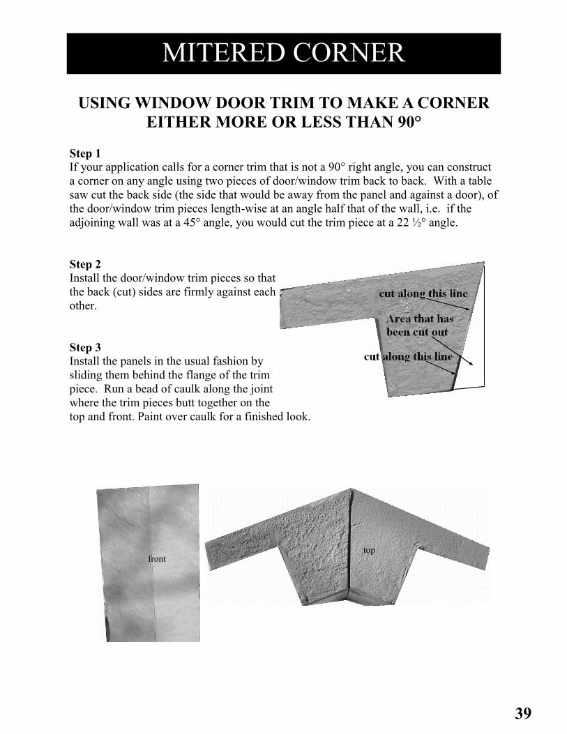
EITHER MORE OR LESS THAN 90° Step 1
If your application calls for a corner trim that is not a 90° right angle, you can construct
a corner on any angle using two pieces of door/window trim back to back. With a table
saw cut the back side (the side that would be away from the panel and against a door), of
the door/window trim pieces length-wise at an angle half that of the wall, i.e. if the
adjoining wall was at a 45° angle, you would cut the trim piece at a 22 ½° angle.
Step 2
Install the door/window trim pieces so that
the back (cut) sides are firmly against each
other.
Step 3
Install the panels in the usual fashion by
sliding them behind the flange of the trim
piece. Run a bead of caulk along the joint
where the trim pieces butt together on the
top and front. Paint over caulk for a finished look.
front top

40
22" RANDOM ROCK MAILBOX INSTALLATION
Unpack and Verify Materials:
1 - Mailbox Enclosure 1 - Mailbox Cover 1 - Metal Mailbox
2 - Removable Brackets (1 top & 1 bottom)
The Hardware Package Contains:
8- 2" Screws 4 - Butterfly Screws
4- 2 ¾" Screws 4 - Washers
2 - Nuts and Bolts (Mailbox door pull)
2– Velcro strips
*Please contact the vendor if materials are missing.
Consider these Points Before Installing:
A) Follow any USPS setback requirements.
B) The front and side edges of the post will end up at 9" back from
the finished front and sides of the mailbox enclosure when installed. Allow for a
24" x 24"
overall footprint making sure that the ground is clear and level.
Do not install in grass areas or lawn. Damage caused by lawn
or garden equipment is not covered under the warranty.
Step 1 - Prepare the Post
A) The mailbox enclosure is designed to fit over a standard 4" x 4" pressure treated
post. Make sure the front post is EXACTLY parallel to the direction you want
the mailbox to face. If the post is off, the mailbox will not face the desired
direction.
B) Make sure the post is plumb in both directions. If the post is not plumb, the mailbox
may appear crooked or skewed once the installation is complete.
C) If possible, leave the post long until the exact height has been measured. Set into
the concrete approximately 18" with an above ground height of at least 36".
Step 2 - Attach the Bottom Bracket
A) Before removing the top and bottom brackets, mark one side for proper orientation
when replaced. (fig. 2A) This will make the screws go back in much easier. Remove the
12 screws holding the bottom bracket into the enclosure. Slide the bottom bracket over the post keeping
the lip on the bottom side. Level the bracket at the desired base height and attach to the
post with 1 - 2" screw per side. Secure through the inner ring of the bracket into the side of
the post. (2B)
Step 3 - Measure and Cut Post
Measure 35" up from the top of the attached bottom bracket. Use a “speed square” to
mark all 4 sides of the post. Cut the post at this height. Be careful to make the top of
the post level.
Step 4 - Setting the Mailbox Enclosure
A) Slide the mailbox enclosure over the post, being careful not to bind the second
bracket as it slides down the post.
B) Set the bottom of the enclosure onto the bottom bracket. Make sure the lip is snug against the rim
of the enclosure as the 3rd bracket locks down onto the top of the post.
C) Secure the bottom of the enclosure to the bracket using the 12 - 2 ½" screws that were removed
in step 2. Drive screws through the face and into the bottom bracket.
2B
4A
Cutaway showing the 3 Support Brackets
(Top bracket removed)
2AMark
41
22" RANDOM ROCK MAILBOX INSTALLATION, Cont.
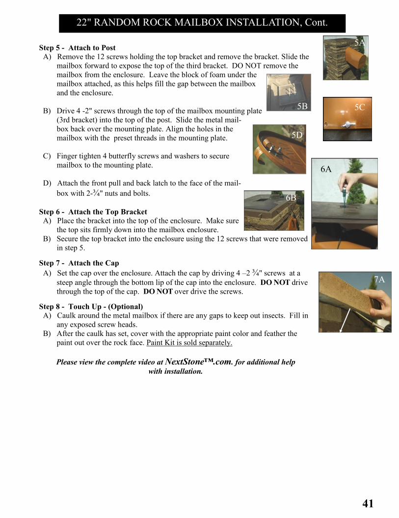
Step 5 - Attach to Post
A) Remove the 12 screws holding the top bracket and remove the bracket. Slide the
mailbox forward to expose the top of the third bracket. DO NOT remove the
mailbox from the enclosure. Leave the block of foam under the
mailbox attached, as this helps fill the gap between the mailbox
and the enclosure.
B) Drive 4 -2" screws through the top of the mailbox mounting plate
(3rd bracket) into the top of the post. Slide the metal mail-
box back over the mounting plate. Align the holes in the
mailbox with the preset threads in the mounting plate.
C) Finger tighten 4 butterfly screws and washers to secure
mailbox to the mounting plate.
D) Attach the front pull and back latch to the face of the mail-
box with 2-¾" nuts and bolts.
Step 6 - Attach the Top Bracket
A) Place the bracket into the top of the enclosure. Make sure
the top sits firmly down into the mailbox enclosure.
B) Secure the top bracket into the enclosure using the 12 screws that were removed
in step 5.
Step 7 - Attach the Cap
A) Set the cap over the enclosure. Attach the cap by driving 4 –2 ¾" screws at a
steep angle through the bottom lip of the cap into the enclosure. DO NOT drive
through the top of the cap. DO NOT over drive the screws.
Step 8 - Touch Up - (Optional)
A) Caulk around the metal mailbox if there are any gaps to keep out insects. Fill in
any exposed screw heads.
B) After the caulk has set, cover with the appropriate paint color and feather the
paint out over the rock face. Paint Kit is sold separately.
Please view the complete video at NextStone™.com. for additional help
with installation.
5A
5B
6A
6B
7A
7A
5D 5C
5D
8C

42
Unpack and Verify Materials:
1 - Mailbox Enclosure (9 pieces) 1 - Metal Mailbox and Flag 1 Cap
4 - Brackets
The Hardware Package Contains:
4 - 1 1/2" Screws 4 - Butterfly Screws
4 - 3" Screws 4 - Washers
40 - 2 1/2" Screws 2 - Nuts and Bolts
*Please contact the vendor if any parts are
missing.
Consider these Points Before Installing:
A) Follow any USPS setback requirements.
B) The front and side edges of the post will end up at
9" back from the finished front and sides of the mailbox enclosure when
installed. Allow for a 24" x 24" overall footprint being sure that the ground
is clear and level.
Do not install in grass areas or lawn. Damage caused by lawn or garden
equipment is not covered under the warranty.
Step 1 - Prepare the Post
A) The mailbox enclosure is designed to fit over a standard 4" x 4" pressure
treated post. Make sure the front post is EXACTLY parallel to the direction
you want the mailbox to face. If the post is off the mailbox will not face the
desired direction.
B) Make sure the post is plumb in both directions. If the post is not plumb, the
mailbox may appear crooked or skewed once the installation is finished.
C) If possible leave the post long until the exact height has been measured. Set
into the concrete approximately 18" with an above ground height of at least
36".
Step 2 - Attach the Bottom Bracket
Slide the bottom bracket (#1)over the post keeping the lip on the bottom
side. Level the bracket at the desired base height and attach to the post
with 1 - 2 " screw per side. Secure through the inner ring of the bracket into the
side of the post.
Step 3– Attach the 2nd bracket. Measure up 24 1/2” from the top of Bracket
#1.Mark a line. Slide the 2nd ring down and secure with the top of the bracket
on this line, using the same procedure as described in Step 2. Make sure the front of
the ring is pointing to the front of the post.
Step 4 - Measure and Cut Post
Measure 35" up from the top of the attached bracket #1. Use a speed square to
mark all 4 sides of the post. Cut the post at this height. Be careful to make the
top of the post level.
Step 5 - Attach 3rd Bracket– Place the 3rd bracket on the top of the post once it is cut to
the correct height. Secure with 4 screws through the top of the bracket into the top of the post.
2
5
6
6C
6
22" SLATESTONE MAILBOX INSTALLATION

43
Step 6 - Attaching the Mailbox Enclosure
A) The enclosure has 9 pieces. All are marked on the inside. Starting with #1, seat
the bottom of the panel in the bottom ring. Secure by face screwing the panel to
the bottom ring using 3 2 1/2” screws. When possible, drive the screw in the grout
lines. This hides the screw head and minimizes any touch up work.
B) Going counter clockwise, seat and secure panels #2, 3 and 4 in the same manner.
C) Attach the address plaque (#9) to the upper front panel(#5) using
(2 ) 1 1/2” screws. (Figs. 6C and 6D)
D) Seat the bottom of the address plaque in the groove of panel#1.
Seat the bottom of panel 5 onto the top of panel 1. Continue
counterclockwise, and attach panels #6,and 7.
E) Slide the metal mailbox through the front opening onto the
mounting plate. Align the holes in the mailbox with the
preset threads in the mounting plate.
F) Finger tighten 4 butterfly screws and washers to secure
mailbox to the mounting plate.
G) Attach the front pull and back latch to the face of the mailbox
with (2)-3/4" nuts and bolts.
H) Attach panel #8 as described earlier.
I) Attach the Flag. Be sure and seat the outer flange to hook
in the slot on the mount. This keeps the flag resting hori-
zontally. Place the bolt through the flag assembly and
mount. Secure on the inside with locking nut. Tighten until
the flag moves with some resistance.
Step 7 - Attach the Top Bracket
A) Place the bracket into the top of the enclosure. Make sure the top seats
firmly down into the mailbox enclosure.
B) Secure the top bracket into the enclosure using 12 screws.
Step 8 - Attach the Cap
A) Seat the cap over the enclosure. Attach
the cap by driving 4 -3" screws at a steep
angle through the bottom lip of the cap
into the enclosure. DO NOT drive
through the top of the cap. DO NOT over
drive the screws.
Step 9 - Touch Up - Optional
A) Caulk around the metal mailbox if there
are any gaps to keep out insects. Fill in any exposed screw heads.
B) After the caulk has set, cover with the appropriate paint color and feather the paint out over the
rock face. Add more texture by using the paint brush to dab a small amount of sand onto the
painted surface.
Please view the complete video at NextStone™.com. for additional help with installation.
6E
7A
7B
88B
8A
5D 6F 6G
6I
44
TOUCH UP
FINISHING THE JOB FOR A
PROFESSIONAL APPEARANCE
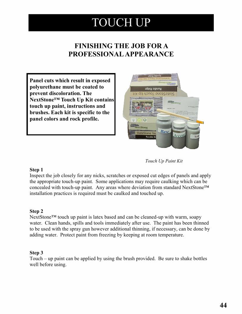
Panel cuts which result in exposed
polyurethane must be coated to
prevent discoloration. The
NextStone™ Touch Up Kit contains
touch up paint, instructions and
brushes. Each kit is specific to the
panel colors and rock profile.
Step 1
Inspect the job closely for any nicks, scratches or exposed cut edges of panels and apply
the appropriate touch-up paint. Some applications may require caulking which can be
concealed with touch-up paint. Any areas where deviation from standard NextStone™
installation practices is required must be caulked and touched up.
Step 2
NextStone™ touch up paint is latex based and can be cleaned-up with warm, soapy
water. Clean hands, spills and tools immediately after use. The paint has been thinned
to be used with the spray gun however additional thinning, if necessary, can be done by
adding water. Protect paint from freezing by keeping at room temperature.
Step 3
Touch – up paint can be applied by using the brush provided. Be sure to shake bottles
well before using.
Touch Up Paint Kit

45
The natural appearance of NextStone™ products are maintained with little
effort. Although NextStone™ products will get dirty, like anything exposed
to the atmosphere, a heavy rain or a simple washing with a garden hose will
do wonders. If additional cleaning is required the following steps outline the
recommended cleaning procedure.
Step 1
Any liquid soap or a light spray of simple green or the equivalent, followed
by light brushing with a soft bristle brush will work with our
product. NextStone™ recommends using whatever product you choose on a
small area first to check for color fastness. You can either use a soft bristle
brush with a garden hose or a pressure washer. If you use a pressure washer,
be SURE not to get closer than 12 inches and not more than 1500 PSI.
Step 2
Although NextStone™ products are not susceptible to mildew, we
recommend using solution X-90. It is very effective in removing mildew
from vinyl siding, and will work on the NextStone™ product. It would be
prudent to test a small area first with any new product.
CLEAN UP

46
FREQUENTLY ASKED QUESTIONS
Q. What is the NextStone™ product made from?
NextStone™ products are manufactured with advanced hybrid polyurethane composites which
allows us to reproduce the most realistic synthetic stone texture and look available.
Q. What is required to cut the NextStone™ product?
NextStone™ products are easily cut with a hand saw, circular saw, or virtually any kind of
carpentry saw or cutting device. (see page 8)
Q. What type of fastener is used to install NextStone™ products?
NextStone™ was designed with ease of installation in mind therefore, depending on the sub-
strate a good quality deck type screw will work. (see page 8)
Q. How are the NextStone™ products installed?
NextStone™ is a mortar-free product that can be easily installed by one or two people using
basic hand or power tools.
Q. How do you avoid repeating color and stone pattern during installation?
NextStone™ panels were designed with basic stone patterns, each numbered on the back of
each panel. These numbers help break up the patterns and color during installation.
Q. What preparation is required to install NextStone™ panels?
NextStone™’s only requirement is a clean and dry substrate as well as 48 hours of acclimation
(see page 9)
Q. What can I apply NextStone™ to? NextStone™ can be easily applied to virtually any solid substrate including block, concrete,
stucco, or wood framed sheathed walls.
Q. What size panels are available?
NextStone™ Castle Rock Panels are 43¼" x 15¼"; Random Rock Panels are 48" x 15 ½";
Slatestone panels are 43" x 8 ¼"; Stacked Stone Panels are 46½" x 13¼"
Q. Is NextStone™ easy to clean?
Because of the closed cell hybrid polyurethane formulation developed by NextStone™, all
products are easily cleaned with a standard garden hose. (see page 48)
Q. Does the product have any R-value?
Yes. Because of NextStone™'s polyurethane formulation, the R value is approximately 4.5 per
inch thickness.
Q. How much does the product weigh?
NextStone™ weighs approximately one pound per square foot making it extremely easy to han-
dle and install, thus eliminating the need for a forklift.
Q. What applications are best suited for NextStone™?
NextStone™ is perfect for almost all commercial and residential, exterior or interior applica-
tions.

47
FREQUENTLY ASKED QUESTIONS Q. What maintenance will be required down the road? Because of the NextStone™ polyurethane formulation and its durable coating there
is virtually no maintenance required. NextStone™ offers a 20 year limited warran-
ty. (see page 57)
Q. How will NextStone™ handle the elements? NextStone™ products have been tested equivalent to 20 years in an advanced
weather testing chamber with very little discoloration to the products.
Q. How does NextStone™ compare in price to the cultured stone type prod-
ucts currently available on the market?
NextStone™ products have been competitively priced and will generally cost less
than cast stone type products. The real savings for the contractor comes from the
cost of labor for installation by a carpenter vs. the cost of labor and material
provided by a mason. With the NextStone™ product the value is added and the
profit is retained by the contractor. For the do-it-yourselfer, the savings come to
those who can install NextStone™ products themselves.
Q. Who can install the NextStone™ panels?
Anyone with a basic understanding of carpentry can easily install NextStone™
products.
Q. Is NextStone™ flammable and what do all those fire test numbers mean?
First, Flame Spread Factor is the distance that the flame spreads across the
specimen piece during the test. This is calculated by measuring the distance across
the panel the flame spreads every 3 seconds during the test. They then compile the
total distance and come up with the Flame Spread Factor. Our product tested at an
average of 30.78.
Second is the Flame Spread Index. This is a mathematical calculation using
calculus and area under a curve to compute a number relative to two points:
Cement and Red Oak. In this index, Red Oak is 100 and cement is 0. There is
some confusion between the tests as our 162 Test now calls this number the
Radiant Panel Index. Ours is 191.13. In the vinyl siding wor ld, anything
under 200 can be placed on wall surfaces. Regardless of tests and numbers, we do
not recommend putting any NextStone™ product near open flames. Although it is
not flammable, it will combust in the presence of flame. We recommend that our
product be placed no closer than 12 inches from areas where an open flame may be
encountered. You may see similar products claiming to have passed the E-84
flame spread test. This is only a portion of E-84 testing and should not be
considered as meeting E-84 requirements. (see page 51)

48
PANELS
Castle Rock Panel dimensions are 15¼" x 43¼" x 1 ½". Each Panel covers 4.03/sq. ft.
Configure Square Footage of area to be covered. (length x width)
Total Square Feet _______ / 4.03sq.ft. = _________ number of Panels necessary.
Round total to nearest box quantities of four (4) panels per box.
Random Rock Panel dimensions are 15 ½" x 48" x 1 ½". Each Panel covers 4.75/sq. ft.
Configure Square Footage of area to be covered. (length x width)
Total Square Feet _______ / 4.75sq.ft. = _________ number of Panels necessary.
Round total to nearest box quantities of four (4) panels per box.
Slatestone Panel dimensions are 8 ¼" x 43" x 1 ¾". Each Panel covers 2.14/sq. ft.
Configure Square Footage of area to be covered. (length x width)
Total Square Feet _______ / 2.14sq.ft. = _________ number of Panels necessary.
Round total to nearest box quantities of eight (8) panels per box.
Stacked Stone Panel dimensions are 13 ¼" x 46½" x 1 ½". Each Panel covers 3.63/sq. ft.
Configure Square Footage of area to be covered. (length x width)
Total Square Feet _______ / 3.63sq.ft. = _________ number of Panels necessary.
Round total to nearest box quantities of five (5) panels per box.
CORNERS
Castle Rock Outside Corner dimensions are 7" x 11" x 15¼"
Configure Vertical Linear Inches.
Total Linear Inches _______ / 15¼"= _____ number of corners necessary.
Castle Rock Outside Corners sit flush with the Castle Rock Panel. Four (4) corners per box, 2
Left / 2 Right.
Random Rock Outside Corner dimensions are 7" x 11" x 15 ½"
Configure Vertical Linear Inches.
Total Linear Inches _______ / 15 ½" = _____ number of pieces of corners.
Random Rock Outside Corners sit flush with each panel. Four (4) corners per box,
2 Left/2Right.
Sandstone Inside Corner dimensions are 3 ½" x 3 ½" x 48"
Configure Vertical Linear Inches.
Total Linear Inches _______ / 48" = _____ number of pieces of corners.
Panels fit behind Corners. Two (2) corners per box. Sandstone Inside Corners can be used
with any rock profile except Slatestone.
TAKE-OFF SHEET

49
Sandstone Outside Corner dimensions are 5 ½" x 5 ½" x 48"
Configure Vertical Linear Inches.
Total Linear Inches _______ / 48" = _____ number of pieces of corners.
Sandstone Outside Corners can be used with any rock profile, except Slatestone. The Panel
will fit behind the corner. Two (2) corners per box.
Sandstone Flush Outside Corner dimensions are 3" x 3" x 48"
Configure Vertical Linear Inches.
Total Linear Inches _______ / 48" = _____ number of pieces of corners.
Sandstone Flush Outside Corners can be used with any rock profile, except Slatestone, and
sit flush to panel ends. Outdoor applications may need caulk or weather seal. Two (2)
corners per box.
Slatestone Outside Corner dimensions are 12 ¾" x 4 ½" x 8 ¼"
Configure Vertical Linear Inches.
Total Linear Inches _______ / 8 ¼" = _____ number of pieces of corners.
Slatestone Outside Corners sit flush with each panel. Four (4) corners per box,
2 Left/2Right.
Stacked Stone Outside Corner dimensions are 4¼" x 13¾" x 13¾"
Configure Vertical Linear Inches.
Total Linear Inches _______ / 13¼" = _____ number of pieces of corners.
Slatestone Outside Corners sit flush with each panel. Four (4) corners per box,
2 Left/2Right.
TAKE-OFF SHEET
CORNERS cont.

50
ACCESSORIES
1. Sandstone Ledger dimensions are 2 ½" x 4" x 48"
Configure Horizontal Linear Feet.
Total Linear Feet ______ / 4' = number of pieces of Ledger.
This accessory is used to trim out the top row and can be used with any rock profile.
Four (4) Ledgers per box.
2. Sandstone Window/Door Trim dimensions are 2 ¼" x 3 ½" x 48"
Configure Vertical and Horizontal Linear Feet.
Total Linear Feet _____ / 4' = number of pieces of window/door trim.
Window/Door Trim will be used on all four window sides as well as the top and sides of
door openings and can be used with any rock profile. Four (4) Trim per box.
3. Sandstone Ledger Outside Corner dimensions are 4 ¼" x 6 ¼" x 2 ½"
Sandstone Ledger Inside Corner dimensions are 9 ¾" x 7 ⅝" x 2 ½"
Ledger Outside and Inside Corners are used to cap corners and show a continuous run of the
Ledger trim piece. Number of pieces depend on number of corners. Two (2) per box,
1 Left / 1 Right.
4. Metal Starter Strips are in 4' lengths.
Configure Horizontal Linear Feet of area to be covered.
Total Linear Feet _______ / 4' =______ number of pieces of starter strip.
- Used to begin the bottom row, Starter Strips are suggested under each panel in order to avoid
face screwing.
5. 12oz. Tubes of Grout _____. (Depending on project, grout/caulk, may or may not be
required).
6. Touch Up Paint Kit _____.
Drystack, Ledgestone, and Random Rock Touch up Paint Kits contain Four 120 cc bottles of
paint, one for each panel color and 1 trim color, plus 4 brushes.
Slatestone Touch Up Paint Kits contain One 120cc and 2 60cc bottles of paint, plus 1 brush.
TAKE-OFF SHEET

51
Note: In all spec data information, weights and dimensions are approximate.
Individual pieces may vary due to the manufacturing process.
Technical Data:
Color Fastness (per ANSI Z 124 xenon arc test): color change @ 2000 hours: 0
Specific Gravity: .6
Insulation value: R 4.5 per inch of thickness
Hardness (durometer D): 68
Coefficient of Expansion (in. /in. F): 4.8"/in./C x 10(-5) (varies depending upon substrate attached to).
Fuel Contributed: 0
Flame Spread (per ASTM E162): Flame Spread Index 191.13
Wind Load Test-( per ASTM E330-02)- Withstands Positive and Negative winds over 200 MPH.
Installation: Detailed installation instructions are available from your local distr ibutor or on line at:
www.NextStone™.com.
Maintenance: NextStone™ products require minimal maintenance. Occasional r insing with water is recommended.
Prior to using any chemical products on NextStone™, test a small inconspicuous area, verifying that no undesired side effects
have occurred.
Warranty: Warranty infor mation is available from your local distr ibutor or online at: www.NextStone™.com.
Important: The infor mation and data herein are believed to be accurate and have been compiled from sources believed
to be reliable. It is offered for you consideration, investigation and verification. Due to the inherent manufacturing
characteristics of polyurethane, and the In Mold coating coloring process of our product, dimensions and weights are
Flame Spread Factor, F9: Heat Evolution Factor, Q: Flame Spread Index, I8: Ave Temp. Rise:
30.78 6.23 191.13 53.8 c
Product Description: NextStone™’s masons and master craftsmen have created products that are an ideal
combination of stone textures and sizes, melding them artistically into an extremely easy to
install paneling system. NextStone™ products are a light weight veneer wall panel system,
providing a very realistic “rock wall” appearance. These products are intended for exterior
applications over masonry, wood framed, or metal framed construction, be it residential or
commercial. The products have been engineered to eliminate additional structural or foundation
support requirements. The basic system requires no caulking.
NextStone™ products are made of uniquely formulated closed cell polyurethane, incorporating
UV inhibitors and fire retardants. The panels and accessory pieces have been cast from real
stone giving them a remarkably realistic rock look. A specially formulated “In Mold Coating”
is chemically and mechanically bonded with the molded surface of the panel. The result is a
lightweight, durable wall panel system with a realistic rock finish.
Limitations: NextStone™ products are intended as wall coverings only and should not be used as pavers or
subjected to foot traffic. NextStone™ products do not add to the structural load bearing
capacity of the substrate to which it is applied. If NextStone™ products are used below grade
or water level, discoloration of the product can occur from the leaching of minerals and
chemicals from the soil and water. The product will not be altered or degraded, but color
fastness is not guaranteed. Avoid installing in locations which will be repeatedly subjected to
abrasion, or repeated contact such as lawn mowers and string trimmers.
SPEC DATA

52
Product Type Length
(inch)
Width
(inch)
Thicknes
s
(inch)
Coverage
Per Piece
Weight
Per
Piece
Qty
Per
Carton
Castle Rock Panel 43.25" 15.5" .88" - 1.44" 4.03 sq. ft. 4.08 lbs. 4
Random Rock Panel 48" 15.5" .88" - 1.5" 4.75 sq. ft. 5.1 lbs. 4
Slatestone Panel 43" 8.25" .88" - 1.5" 2.14 sq. ft. 2.5 lbs. 8
Stacked Stone Panel 46.5" 13.25" .88" - 1.5" 3.63 sq. ft. 4.30 lbs. 5
Accent Rocks, Large 11.5" 15.5" 1.5" 1.2 sq. ft. .94 lbs. 3
Accent Rocks, Small 7" 15.5" 1.5" .63 sq. ft. .71 lbs. 3
Sandstone Ledger 48" 4" 2.5" .6 sq. ft. 2.9 lbs. 4
Outside Ledger Corner 6.25" x 4.25" 4" 2.5" 10.25" .65 lbs. 2
Inside Ledger Corner 9.75" x 7.63" 4" 2.5" 17.5" .67 lbs. 2
Sandstone Window/Door Trim 48" 3.5" 2.25" 1.4 sq. ft. 2.5 lbs. 4
Sandstone Inside Corner 48" 3.5" each leg 2.63" 2.0 sq. ft. 5.1 lbs. 2
Sandstone Outside Corner 48" 5.5" each leg 2.63" 4.0 sq. ft. 6.0 lbs 2
Flush Mount Outside Corner 48" 3"(each side) 1.5" 2.0 sq. ft. 2.47 lbs. 2
Castle Rock Outside Corner 7" x 11" 15.25" 1.5" 1.41 sq. ft. 0.62 lbs. 4
Random Rock Outside Corner 7" x 11" 15.5" 1.5" 1.7 sq. ft. 1.69 lbs. 4
Slatestone Outside Corner 4.5" x 12.75" 8.25" 1.5" 1 sq. ft. 1.0 lbs. 4
Stacked Stone Outside Corner 4.25" x
13.25"
13.25" 1.5" 1.21 sq. ft. 0.6 lbs. 4
Mounting Blocks Large 10" 13" 2.25" n/a 1.75 lbs. 1
Mounting Blocks Small 8" 9" 2.25" n/a 1 lbs. 1
Starter Strip 48" 2.25" 26 gauge n/a .9 lbs. n/a
Slatestone Post Cover 41" 8" 8" n/a 6.61lbs 1 post
Slatestone 2pc Post Cover 41” 8” 8” n/a 6.61 1 post
Post Cover Cap 10.5” 10.5” 3.5” n/a 1.0 lbs. 1 cap
30" Slatestone Column Wrap 16” 16” 30” n/a 25.0 lbs 1
Sandstone 18" Column Wrap Cap 18.5" 18.5" 1.5" 2.38 sq. ft. 2.84 1
22" Slatestone & Random Rock
Mailbox Kit
52" 22" x 22" 1.5" n/a 42.9 lbs. 1 kit
22" Slatestone and Random Rock
Mailbox Cap
23" 23" 4.75" n/a 4.4 lbs. 1
SPEC DATA
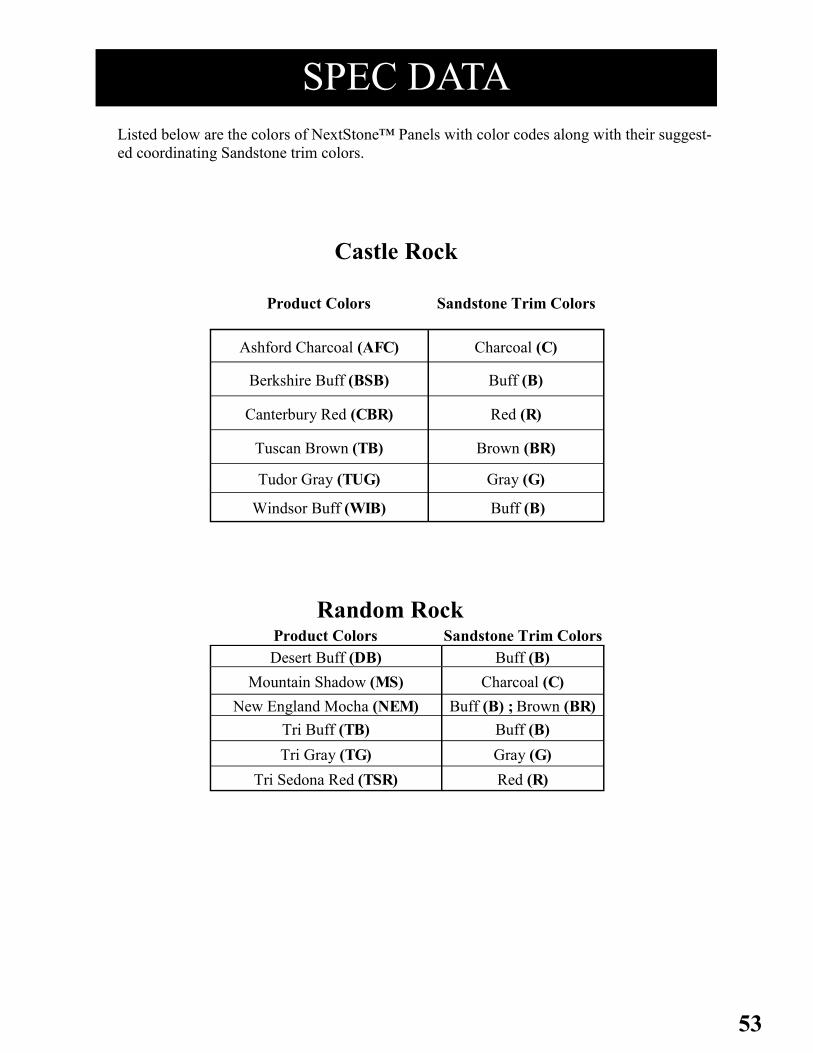
53
SPEC DATA
Product Colors Sandstone Trim Colors
Ashford Charcoal (AFC) Charcoal (C)
Berkshire Buff (BSB) Buff (B)
Canterbury Red (CBR) Red (R)
Tuscan Brown (TB) Brown (BR)
Tudor Gray (TUG) Gray (G)
Windsor Buff (WIB) Buff (B)
Castle Rock
Listed below are the colors of NextStone™ Panels with color codes along with their suggest-
ed coordinating Sandstone trim colors.
Product Colors Sandstone Trim Colors
Desert Buff (DB) Buff (B)
Mountain Shadow (MS) Charcoal (C)
New England Mocha (NEM) Buff (B) ; Brown (BR)
Tri Buff (TB) Buff (B)
Tri Gray (TG) Gray (G)
Tri Sedona Red (TSR) Red (R)
Random Rock

54
SPEC DATA
Listed below are the colors of NextStone™ Panels with color codes along with their suggest-
ed coordinating Sandstone trim colors.
Product Colors Sandstone Trim Colors
Arizona Red (AR) Red (R)
Brunswick Brown (BB) Brown (BR)
Midnight Ash (MA) Charcoal (C)
Onyx (ON) Onyx (ON)
Pewter (PW) Gray (G)
Rundle Ridge (RUR) Charcoal (C),Gray (G)
Rocky Mountain Graphite(RMG) Graphite (GPH)
Sahara (SH) Buff (B)
Slatestone
Product Colors Sandstone Trim Colors
Bedford Charcoal (BC) Charcoal (C)
Carolina Cocoa (CC) Buff (B)
Kentucky Gray (KG) Gray (G)
Sandy Buff (SB) Buff (B)
Volcanic Gray (VG) Gray (G)
Walnut Brown (WB) Brown (BR)
Stacked Stone
55
Effective date: 5/28/04
Supersedes: n/a
Product: Polyurethane siding panels and accessories
Product Use: Exterior and interior siding product
Distributor: NextStone™
P.O. Box 39914
Denver, Co. 80239-0914
(303) 371-8232
(303)371-8296 (fax)
www.NextStone™.com
Section 2: COMPOSITION INFORMATION ON INGREDIENTS:
*No Hazardous Ingredients*
These rigid urethane panels are manufactured from polyurethane, inert fillers, process aids, waxes, colorants and fire retardants.
Section 3: PHYSICAL / CHEMICAL CHARACTERISTICS: Appearance and Odor: Solid, odorless panel, various colors
Boiling Point (degrees Fahrenheit): Not applicable
Vapor Pressure: Solid, Not applicable
Percent Volatile by Volume: 0
Solubility in Water: 0
Specific Gravity (water = 1): .6
Melting Point (degrees Fahrenheit): Not applicable
Evaporation Rate (butyl acetate): Not applicable
Section 4: FIRE AND EXPLOSION DATA:
Flash Point: Not applicable
Auto-ignition temperature: 500 degrees Fahrenheit
Extinguishing Media: Water, CO2, or sand
Special Procedures: Firefighters and others who may be exposed to products of combustion should wear full
protective clothing including self-contained breathing apparatus.
.
Section 1: PRODUCT AND COMPANY IDENTIFICATION:
Component: % Weight Case No.
Polyurethane (rigid)
94.8% None Assigned
Proprietary Ingredients 5.1% n/a (non hazardous)
Material Safety
Data Sheet

56
Component: acgih tlv (units) Osha pel (units)
Processing Waste 5 mg / cubic meter (8 hour twa) 5 mg / cubic meter (8 hour twa)
Processing Waste 10 mg / cubic meter (stel) 10 mg / cubic meter (stel)
Section 5: REACTIVITY DATA:
Stability: Stable under normal conditions
Incompatibility
(Materials to avoid): Avoid open flame. Avoid contact with oxidizing agents. Product may auto-
ignite at temperatures in excess of 450 degrees Fahrenheit.
Hazardous decomposition products: Thermal and / or thermal oxidative decomposition can produce irritation and
toxic fumes and gasses including carbon monoxide, hydrogen cyanide
Section 6: HEALTH HAZARD DATA: Rigid polyurethane is not considered or listed as a hazardous chemical in 29 CFR 1910 subpart Z, Product Safety Act (15
U.S.C. 2051), or the Federal Hazardous substances Act (15 U.S.C. 1261)
Foam dust may be a by-product of the installation process.
Ingestion: Not applicable
Eye Contact: Eye irritation possible
Skin Contact: Waste generated from processing may evoke allergic contact dermatitis in
sensitized individuals.
EMERGENCY AND FIRST AID PROCEDURES:
Eye Contact: Immediately flush with copious amounts of water. Remove to fresh air. If irritation persists, get medical
attention.
Skin Contact: Wash affected area with soap and water. If rash or persistent irritation or dermatitis occurs seek medical
attention.
Inhalation: Remove to fresh air. If persistent irritation, severe coughing or breathing difficulty occurs, seek medical
attention.
Ingestion: Not applicable
Section 7: TOXICITY DATA:
Processing Dust: May cause nasal dryness, irritation and obstructions, coughing, wheezing, and sneezing. Sinusitis and
prolonged colds have also been reported. Depending on the type, processing dust may cause respiratory
sensitization and or irritation.
Section 8: PROTECTION INFORMATION AND CONTROL MEASURES:
Respiratory protection: Dust mask, if dust exceeds allowable exposure limits wear a NIOSH / OSHA
approved respirator.
Eye protection: Safety glasses or goggles
Skin protection: None required (gloves optional)
Engineering Controls: Provide adequate general and local exhaust ventilation to most exposures.
Section 8: PRECAUTIONS FOR SAFE HANDLING AND USE: Release / Spill Handling: Scrap material or dust from sawing or cutting should be handled as an inert
solid, in the fashion of sand.
Waste Disposal Method: Landfill as non-hazardous waste.
Storage: Panels and accessories should be stored in original boxes to prevent damage
or deformation of the product.
Important: The information and data herein are believed to be accurate and have been
compiled from sources believed to be reliable. It is offered for your
consideration, investigation and verification. Buyer assumes all risk of use,
storage and handling of the product in compliance with applicable federal,
state and local laws and regulations. NextStone™ makes no warranty of any
kind, express or implied, concerning the accuracy or completeness of the
information and data herein. The implied warranties of merchantability and
fitness for a particular purpose are specifically excluded. NextStone™ will
not be liable for claims relating to any party’s use of or reliance on
information and data contained herein regardless of whether it is claimed that
the information and data are inaccurate, incomplete or otherwise misleading.

57
Warranty Important:
All Claims under this warranty must be reported to NextStone™ within sixty (60) days of the date that the defect is
first discovered. Claimant should describe the defect and provide name, address, date of installation and warranty
certificate number if available.
Original Owner’s 20 Year Limited Liability Warranty:
NextStone™ rock-face paneling and accessories are manufactured using quality raw materials and
produced with engineering excellence designed for years of maintenance free use. NextStone™ warrants exclu-
sively to the original purchaser of our product for a period of 20 years from the original date of purchase, and is the
owner of the property to which our products were originally applied, that the NextStone™ rock-face paneling
applied to that property will not fade, peel, rot, blister, rust, flake, chip, crack, corrode or be consumed by termites
solely as a result of defects in material or manufacturing. Should any of these defects occur during the 20 year
warranty period, while he or she is the owner of the property to which the NextStone™ urethane rock-face product
(s) were applied, and provided that the terms and conditions of this warranty are met and the claim is properly
reported as stated below, NextStone™ will, at its discretion, repair or replace the material per the schedule below
to the original homeowner, the NextStone™ rock-face paneling and accessories determined to be defective, in
accordance with the terms and conditions of this warranty. In lieu of replacement NextStone™ reserves the right
in its sole discretion to refund actual monies, per the table below rather than replacing the products determined to
be defective.
Conditions Not Covered By This Warranty:
This warranty covers only the specified damages arising solely from defects in the manufacturing of NextStone™'s
urethane rock-face paneling and accessories and only if they occur under normal use and service. It does not
cover, and NextStone™ is not liable for, conditions or failure of or damage to such products resulting from faulty
or improper installation, settlement of the structure on which products are installed or shifting of structural mem-
bers or adjoining surfaces, failure of the structure (including foundations and walls), accidental damage or negli-
gence, intentional acts or damage, fire, wind, flood, lightning, acts of
God, misuse, improper care or failure to provide reasonable and nec-
essary maintenance of the product, normal and expected weather of
the
surface, mildew, exposure to harmful chemicals or vapors or acid
rain, surface discoloration due to atmospheric pollution,
contaminates, staining or oxidation, distortion or warping due to
unusual heat sources (including outdoor grills and reflection from
windows or foil sheathing), or the installation of accessory products
which are Incompatible with the NextStone™ paneling or which are
installed in a manner detrimental to the performance of the
NextStone™ siding. Proper installation is important to the finished
look of the product. Gapping between panels or accessories is not
covered under this warranty. This warranty covers only unpainted
products and is inapplicable to finishing applied to the product by the
homeowner. NextStone™ shall be allowed a reasonable opportunity
and time to investigate the claim and to inspect the rock-face
paneling for defects before repairs are begun. You will be requested
to allow photos and/or samples to be taken, at NextStone™’s option,
in connection with this investigation. If your rock-face paneling
contains manufacturing defects covered by this warranty,
NextStone™ will, at its option, repair or replace the urethane rock-
face paneling determined to be defective in accordance with the
terms of this
warranty, or, in lieu of repair or replacement, NextStone™ may re-
fund the pro-rated portion of the wholesale price of the products
determined to be defective. This warranty shall not cover and
NextStone™ shall not be responsible for costs and expenses incurred
with respect to the removal of defective NextStone™ products or the
installation of replacement materials, including but not limited to
labor and freight. The warranty period shall not be extended by any
such repair or refund settlements on defective siding or accessories.
Due to normal weathering, replacement siding may vary in color and
gloss from products originally installed. Such variances are not de-
fects and NextStone™ is not liable for such variances. NextStone™
reserves the right to discontinue or make changes to any of its prod-
ucts. If products covered by this warranty are no longer available,
NextStone™ shall have the right to substitute a product that in
Years from
Date of
Purchase
NextStone
™’s Cover-
age
Original
Homeowner
Responsibility
1 100% 0%
2 95% 5%
3 90% 10%
4 85% 15%
5 80% 20%
6 75% 25%
7 70% 30%
8 65% 35%
9 60% 40%
10 55% 45%
11 50% 50%
12 45% 55%
13 40% 60%
14 35% 65%
15 30% 70%
16 25% 75%
17 20% 80%
18 15% 85%
19 10% 90%
20 5% 95%
Some states do not allow the exclusion or limitations to incidental or
consequential damages, so the above limitation or exclusion may not
apply to you. This warranty gives you specific legal rights, and you may
have other rights which vary from.

58
NOTES ____________________________________________________________________________________________________________________________________________________________________________________________________________________________________________________________________________________________________________________________________________________________________________________________________________________________________________________________________________________________________________________________________________________________________________________________________________________________________________

59
NOTES ____________________________________________________________________________________________________________________________________________________________________________________________________________________________________________________________________________________________________________________________________________________________________________________________________________________________________________________________________________________________________________________________________________________________________________________________________________________________________________

60
Inspired by Nature……
Designed by NextStone™.
www.NextStone™.com 866-371-8232
VER. 07.27.16