installation millennium™ rooftop manual … · 524158-yim-a-0509 johnson controls unitary...
TRANSCRIPT

ISO 9001Certified Quality
Management System
CONTENTSNOMENCLATURE . . . . . . . . . . . . . . . . . . . . . . . . . . . 5GENERAL . . . . . . . . . . . . . . . . . . . . . . . . . . . . . . . . . 7SAFETY CONSIDERATIONS . . . . . . . . . . . . . . . . . . 7INSTALLATION . . . . . . . . . . . . . . . . . . . . . . . . . . . . . 8GAS HEATING. . . . . . . . . . . . . . . . . . . . . . . . . . . . . 16START-UP . . . . . . . . . . . . . . . . . . . . . . . . . . . . . . . . 59GAS FURNACE OPERATING INSTRUCTIONS. . . 64SERVICE . . . . . . . . . . . . . . . . . . . . . . . . . . . . . . . . . 66MAINTENANCE . . . . . . . . . . . . . . . . . . . . . . . . . . . . 83
See the following pages for a complete Table of Contents.
NOTES, CAUTIONS AND WARNINGS
Installer should pay particular attention to the words: NOTE,CAUTION, and WARNING. Notes are intended to clarify ormake the installation easier. Cautions are given to preventequipment damage. Warnings are given to alert installerthat personal injury and/or equipment damage may result ifinstallation procedure is not handled properly.
INSTALLATION MANUAL
CAUTION: READ ALL SAFETY GUIDES BEFORE YOU BEGIN TO INSTALL YOUR UNIT.
SAVE THIS MANUAL
MILLENNIUM™ ROOFTOP25, 30 & 40 TON
524158-YIM-A-0509
MODELS: Z32
Z33
Z34

524158-YIM-A-0509
2 Johnson Controls Unitary Products
TABLE OF CONTENTSNOMENCLATURE. . . . . . . . . . . . . . . . . . . . . . . . . . . 5GENERAL . . . . . . . . . . . . . . . . . . . . . . . . . . . . . . . . . 7SAFETY CONSIDERATIONS . . . . . . . . . . . . . . . . . . 7
NOTES, CAUTIONS AND WARNINGS. . . . . . . . . . . . . . . 7GAS FIRED MODELS . . . . . . . . . . . . . . . . . . . . . . . . . . . . 7
WHAT TO DO IF YOU SMELL GAS . . . . . . . . . . . . . . . . . . . . . 7ALL MODELS. . . . . . . . . . . . . . . . . . . . . . . . . . . . . . . . . . . 7INSPECTION . . . . . . . . . . . . . . . . . . . . . . . . . . . . . . . . . . . 7REFERENCE . . . . . . . . . . . . . . . . . . . . . . . . . . . . . . . . . . . 8APPROVALS . . . . . . . . . . . . . . . . . . . . . . . . . . . . . . . . . . . 8
INSTALLATION . . . . . . . . . . . . . . . . . . . . . . . . . . . . . 8LIMITATIONS. . . . . . . . . . . . . . . . . . . . . . . . . . . . . . . . . . . 8LOCATION. . . . . . . . . . . . . . . . . . . . . . . . . . . . . . . . . . . . . 8RIGGING AND HANDLING . . . . . . . . . . . . . . . . . . . . . . . 12CLEARANCES. . . . . . . . . . . . . . . . . . . . . . . . . . . . . . . . . 12DUCTWORK . . . . . . . . . . . . . . . . . . . . . . . . . . . . . . . . . . 13AIR HOODS FOR FIXED OUTSIDE AIR(UNITS WITH MANUAL ECONOMIZER) . . . . . . . . . . . . 13
AIR HOODS FOR ECONOMIZER . . . . . . . . . . . . . . . . . . 13AIR HOODS FOR EXHAUST AIR . . . . . . . . . . . . . . . . . . 13CONDENSATE DRAIN . . . . . . . . . . . . . . . . . . . . . . . . . . 13SERVICE ACCESS . . . . . . . . . . . . . . . . . . . . . . . . . . . . . 14COMPRESSORS. . . . . . . . . . . . . . . . . . . . . . . . . . . . . . . 14FILTERS . . . . . . . . . . . . . . . . . . . . . . . . . . . . . . . . . . . . . 14THERMOSTAT (CONSTANT VOLUME UNITS) . . . . . . . 14SPACE SENSOR (VARIABLE AIR VOLUME UNITS). . . 14POWER AND CONTROL WIRING . . . . . . . . . . . . . . . . . 15
POWER WIRING DETAIL . . . . . . . . . . . . . . . . . . . . . . . . . . . . 15ERV . . . . . . . . . . . . . . . . . . . . . . . . . . . . . . . . . . . . . . . . . . . . . 15
GAS HEATING . . . . . . . . . . . . . . . . . . . . . . . . . . . . 16GAS PIPING . . . . . . . . . . . . . . . . . . . . . . . . . . . . . . . . . . 16GAS CONNECTION . . . . . . . . . . . . . . . . . . . . . . . . . . . . 16VENT AND COMBUSTION AIR. . . . . . . . . . . . . . . . . . . . 17ELECTRIC HEAT. . . . . . . . . . . . . . . . . . . . . . . . . . . . . . . 18HOT WATER HEAT . . . . . . . . . . . . . . . . . . . . . . . . . . . . . 18
PIPING CONNECTIONS . . . . . . . . . . . . . . . . . . . . . . . . . . . . . 18STEAM HEAT . . . . . . . . . . . . . . . . . . . . . . . . . . . . . . . . . 19
PIPING CONNECTIONS . . . . . . . . . . . . . . . . . . . . . . . . . . . . . 19STATIC PRESSURE CONTROL PLASTIC TUBING . . . 20EXHAUST STATIC PRESSURE . . . . . . . . . . . . . . . . . . . 20CFM, STATIC PRESSURE, AND POWER - ALTITUDE AND TEMPERATURE CORRECTIONS . . . . . . . . . . . . 45
START-UP . . . . . . . . . . . . . . . . . . . . . . . . . . . . . . . . 59COMPRESSOR ROTATION . . . . . . . . . . . . . . . . . . . . . . 59
SUPPLY AIR FAN INSTRUCTIONS . . . . . . . . . . . . . . . . 59CHECK BLOWER BEARING SET SCREWS . . . . . . . . . . . . . 59CHECKING SUPPLY AIR CFM . . . . . . . . . . . . . . . . . . . . . . . 59FAN ROTATION . . . . . . . . . . . . . . . . . . . . . . . . . . . . . . . . . . . 59BELT TENSION . . . . . . . . . . . . . . . . . . . . . . . . . . . . . . . . . . . 59AIR BALANCE. . . . . . . . . . . . . . . . . . . . . . . . . . . . . . . . . . . . . 59CHECKING AIR QUANTITY . . . . . . . . . . . . . . . . . . . . . . . . . . 60SUPPLY AIR DRIVE ADJUSTMENT . . . . . . . . . . . . . . . . . . . 61
SYSTEM SETPOINTS. . . . . . . . . . . . . . . . . . . . . . . . . . . 61CONSTANT VOLUME AND VARIABLE AIR VOLUME: . . . . . 61
GAS FURNACE OPERATINGINSTRUCTIONS . . . . . . . . . . . . . . . . . . . . . . . . . . . 64
TO LIGHT THE MAIN BURNERS . . . . . . . . . . . . . . . . . . 64TO SHUT DOWN. . . . . . . . . . . . . . . . . . . . . . . . . . . . . . . 64POST-START CHECKLIST (GAS) . . . . . . . . . . . . . . . . . 64MANIFOLD GAS PRESSURE ADJUSTMENT . . . . . . . . 64BURNER INSTRUCTIONS . . . . . . . . . . . . . . . . . . . . . . . 65ADJUSTMENT OF TEMPERATURE RISE . . . . . . . . . . . 65CHECKING GAS INPUT . . . . . . . . . . . . . . . . . . . . . . . . . 65
NATURAL GAS . . . . . . . . . . . . . . . . . . . . . . . . . . . . . . . . . . . . 65ELECTRIC HEATING . . . . . . . . . . . . . . . . . . . . . . . . . . . 66COOLING OPERATING INSTRUCTIONS . . . . . . . . . . . 66
COMPRESSOR . . . . . . . . . . . . . . . . . . . . . . . . . . . . . . . . . . . 66INTERNAL WIRING . . . . . . . . . . . . . . . . . . . . . . . . . . . . . . . . 66CONDENSER FANS. . . . . . . . . . . . . . . . . . . . . . . . . . . . . . . . 66
SERVICE . . . . . . . . . . . . . . . . . . . . . . . . . . . . . . . . . 66REFRIGERATION SYSTEM . . . . . . . . . . . . . . . . . . . . . . 66COMPRESSORS . . . . . . . . . . . . . . . . . . . . . . . . . . . . . . 66MOTORS. . . . . . . . . . . . . . . . . . . . . . . . . . . . . . . . . . . . . 66
INDOOR BLOWER MOTORS. . . . . . . . . . . . . . . . . . . . . . . . . 66POWER EXHAUST OR RETURN AIR FAN MOTORS . . . . . 66CONDENSER FAN MOTORS . . . . . . . . . . . . . . . . . . . . . . . . 66DRAFT MOTOR (GAS FURNACE). . . . . . . . . . . . . . . . . . . . . 66
GAS FURNACE SAFETY FEATURES . . . . . . . . . . . . . . 83COMBUSTION AIR PROVING . . . . . . . . . . . . . . . . . . . . . . . . 83ROLLOUT . . . . . . . . . . . . . . . . . . . . . . . . . . . . . . . . . . . . . . . . 83
MAINTENANCE . . . . . . . . . . . . . . . . . . . . . . . . . . . . 83NORMAL MAINTENANCE . . . . . . . . . . . . . . . . . . . . . . . 83
FILTERS . . . . . . . . . . . . . . . . . . . . . . . . . . . . . . . . . . . . . . . . . 83MOTORS. . . . . . . . . . . . . . . . . . . . . . . . . . . . . . . . . . . . . . . . . 83FAN DRIVES. . . . . . . . . . . . . . . . . . . . . . . . . . . . . . . . . . . . . . 84OUTDOOR COIL. . . . . . . . . . . . . . . . . . . . . . . . . . . . . . . . . . . 84
GAS BURNER. . . . . . . . . . . . . . . . . . . . . . . . . . . . . . . . . 84TO CLEAN BURNERS . . . . . . . . . . . . . . . . . . . . . . . . . . . . . . 84COMBUSTION AIR DISCHARGE. . . . . . . . . . . . . . . . . . . . . . 84CLEANING FLUE PASSAGES AND HEATING ELEMENTS . 84
SECURE OWNERS APPROVAL . . . . . . . . . . . . . . . . . . 85

524158-YIM-A-0509
Johnson Controls Unitary Products 3
LIST OF FIGURESFig. # Pg. #
1 COMPONENT LOCATION. . . . . . . . . . . . . . . . . . . . . . . 62 TYPICAL RIGGING . . . . . . . . . . . . . . . . . . . . . . . . . . . 103 CENTER OF GRAVITY . . . . . . . . . . . . . . . . . . . . . . . . 114 RECOMMENDED DRAIN PIPING . . . . . . . . . . . . . . . . 145 TYPICAL THERMOSTAT WIRING . . . . . . . . . . . . . . . 146 TYPICAL GAS PIPING CONNECTION . . . . . . . . . . . . 167 VENT AND COMBUSTION AIR HOODS. . . . . . . . . . . 178 CLEARANCES . . . . . . . . . . . . . . . . . . . . . . . . . . . . . . . 179 HOT WATER PIPING CROSS-SECTION . . . . . . . . . . 1910 STEAM PIPING CROSS-SECTION . . . . . . . . . . . . . . . 1911 BOTTOM SUPPLY AND RETURN . . . . . . . . . . . . . . . 2112 END RETURN, BOTTOM SUPPLY . . . . . . . . . . . . . . . 2213 BOTTOM RETURN, FRONT & REAR SUPPLY . . . . . 2314 END RETURN, FRONT & REAR SUPPLY . . . . . . . . . 2415 FIELD INSTALLED DISCONNECT . . . . . . . . . . . . . . . 4316 40 TON CONDENSER DETAIL . . . . . . . . . . . . . . . . . . 4317 PARTIAL ROOF CURB MODEL 1RC0455P . . . . . . . . 4418 ALTITUDE/TEMPERATURE CONVERSION
FACTOR . . . . . . . . . . . . . . . . . . . . . . . . . . . . . . . . . . . 4619 FAN PERFORMANCE - 25 TON . . . . . . . . . . . . . . . . . 4820 FAN PERFORMANCE - 30 TON . . . . . . . . . . . . . . . . . 5021 FAN PERFORMANCE - 40 TON . . . . . . . . . . . . . . . . . 5222 POWER EXHAUST - ONE FORWARD CURVE FAN
- 25 TONS . . . . . . . . . . . . . . . . . . . . . . . . . . . . . . . . . . 5623 POWER EXHAUST - TWO FORWARD CURVED FANS
- 30 & 40 TONS . . . . . . . . . . . . . . . . . . . . . . . . . . . . . . 5824 BELT TENSION ADJUSTMENT . . . . . . . . . . . . . . . . . 5925 TYPICAL GAS VALVES . . . . . . . . . . . . . . . . . . . . . . . . 6526 TYPICAL FLAME APPEARANCE . . . . . . . . . . . . . . . . 6627 HOT WATER COIL - 25 & 30 TON, 1 ROW,
AT 10 GPM . . . . . . . . . . . . . . . . . . . . . . . . . . . . . . . . . 7028 HOT WATER COIL - 25 & 30 TON, 1 ROW,
AT 20 GPM . . . . . . . . . . . . . . . . . . . . . . . . . . . . . . . . . 70
Fig. # Pg. #
29 HOT WATER COIL - 25 & 30 TON, 1 ROW,AT 30 GPM . . . . . . . . . . . . . . . . . . . . . . . . . . . . . . . . . 71
30 HOT WATER COIL - 25 & 30 TON, 1 ROW,AT 40 GPM . . . . . . . . . . . . . . . . . . . . . . . . . . . . . . . . . 71
31 HOT WATER COIL - 25 & 30 TON, 2 ROW,AT 60 GPM . . . . . . . . . . . . . . . . . . . . . . . . . . . . . . . . . 72
32 HOT WATER COIL - 25 & 30 TON, 2 ROW,AT 80 GPM . . . . . . . . . . . . . . . . . . . . . . . . . . . . . . . . . 72
33 HOT WATER COIL - 40 TON, 1 ROW, AT 10 GPM . . 7334 HOT WATER COIL - 40 TON, 1 ROW, AT 20 GPM . . 7335 HOT WATER COIL - 40 TON, 1 ROW, AT 30 GPM . . 7436 HOT WATER COIL - 40 TON, 1 ROW, AT 40 GPM . . 7437 HOT WATER COIL - 40 TON, 2 ROW, AT 20 GPM . . 7538 HOT WATER COIL - 40 TON, 2 ROW, AT 40 GPM . . 7539 HOT WATER COIL - 40 TON, 2 ROW, AT 60 GPM . . 7640 HOT WATER COIL - 40 TON, 2 ROW, AT 80 GPM . . 7641 STEAM COIL - 25 & 30 TON (1 ROW) . . . . . . . . . . . . 7742 STEAM COIL - 40 TON (1 ROW) . . . . . . . . . . . . . . . . 7743 TYPICAL CONTROL WIRING . . . . . . . . . . . . . . . . . . . 7844 LEGEND . . . . . . . . . . . . . . . . . . . . . . . . . . . . . . . . . . . 7945 TYPICAL 25 TON POWER WIRING . . . . . . . . . . . . . . 8046 TYPICAL STANDARD GAS HEAT WIRING . . . . . . . . 8147 TYPICAL MODULATING GAS HEAT WIRING . . . . . . 8248 TYPICAL FLUE BAFFLE . . . . . . . . . . . . . . . . . . . . . . . 8549 25 TON CHARGING CURVE . . . . . . . . . . . . . . . . . . . 8650 30 TON CHARGING CURVE . . . . . . . . . . . . . . . . . . . 8751 40 TON CHARGING CURVE . . . . . . . . . . . . . . . . . . . 8852 PRESSURE DROP DRY EVAPORATOR COIL VS
SUPPLY AIR CFM - 25 TON . . . . . . . . . . . . . . . . . . . . 8953 PRESSURE DROP DRY EVAPORATOR COIL VS
SUPPLY AIR CFM - 30 TON . . . . . . . . . . . . . . . . . . . . 9054 PRESSURE DROP DRY EVAPORATOR COIL VS
SUPPLY AIR CFM - 40 TON . . . . . . . . . . . . . . . . . . . . 9155 R-410A QUICK REFERENCE GUIDE . . . . . . . . . . . . . 92

524158-YIM-A-0509
4 Johnson Controls Unitary Products
LIST OF TABLES
Tbl. # Pg. #
1 COOLING & ELECTRICAL APPLICATION . . . . . . . . . . 82 COOLING & ELEC. APP. LIMITATIONS . . . . . . . . . . . . 83 STANDARD GAS HEATING CAPACITIES . . . . . . . . . . 94 TEMPERATURE RISE . . . . . . . . . . . . . . . . . . . . . . . . . . 95 MINIMUM HEATING CFM . . . . . . . . . . . . . . . . . . . . . . . 96 MODULATING GAS HEATING CAPACITIES . . . . . . . . 97 MODULATING HEAT . . . . . . . . . . . . . . . . . . . . . . . . . . 108 UNIT WEIGHTS . . . . . . . . . . . . . . . . . . . . . . . . . . . . . . 119 SUPPLY FAN MOTOR VFD WEIGHTS . . . . . . . . . . . . 1110 EXHAUST FAN MOTOR VFD WEIGHTS . . . . . . . . . . 1111 UNIT CORNERWEIGHT . . . . . . . . . . . . . . . . . . . . . . . 1212 UNIT CENTER OF GRAVITY . . . . . . . . . . . . . . . . . . . . 1213 CONTROL WIRE SIZES . . . . . . . . . . . . . . . . . . . . . . . 1414 PIPE SIZES . . . . . . . . . . . . . . . . . . . . . . . . . . . . . . . . . 1615 GENERAL PHYSICAL DATA . . . . . . . . . . . . . . . . . . . . 2516 REFRIGERANT FACTORY CHARGE R-410A . . . . . . 2617 ELECTRICAL DATA 25 TON BASIC UNIT R-410A . . . 2618 ELECTRICAL DATA 30 TON BASIC UNIT R-410A . . . 2719 ELECTRICAL DATA 40 TON BASIC UNIT R-410A . . . 2720 ELECTRICAL DATA 25 TON W/ELECTRIC HEAT
R-410A . . . . . . . . . . . . . . . . . . . . . . . . . . . . . . . . . . . . . 2821 ELECTRICAL DATA 30 TON W/ELECTRIC HEAT
R-410A . . . . . . . . . . . . . . . . . . . . . . . . . . . . . . . . . . . . . 2922 ELECTRICAL DATA 40 TON W/ELECTRIC HEAT
R-410A . . . . . . . . . . . . . . . . . . . . . . . . . . . . . . . . . . . . . 3023 ELECTRICAL DATA 25 TON W/POWER EXHAUST
R-410A . . . . . . . . . . . . . . . . . . . . . . . . . . . . . . . . . . . . . 3124 ELECTRICAL DATA 30 TON W/POWER EXHAUST
R-410A . . . . . . . . . . . . . . . . . . . . . . . . . . . . . . . . . . . . . 3225 ELECTRICAL DATA 40 TON W/POWER EXHAUST
R-410A . . . . . . . . . . . . . . . . . . . . . . . . . . . . . . . . . . . . . 3326 ELECTRICAL DATA 25 TON W/ELECTRIC HEAT
AND POWER EXHAUST R-410A . . . . . . . . . . . . . . . . 3427 ELECTRICAL DATA 30 TON W/ELECTRIC HEAT
AND POWER EXHAUST R-410A . . . . . . . . . . . . . . . . 3728 ELECTRICAL DATA 40 TON W/ELECTRIC HEAT AND
POWER EXHAUST R-410A . . . . . . . . . . . . . . . . . . . . 4029 ALTITUDE CORRECTION FACTORS . . . . . . . . . . . . . 45
Tbl. # Pg. #
30 FAN PERFORMANCE - 25 TON . . . . . . . . . . . . . . . . . 4731 FAN PERFORMANCE - 30 TON . . . . . . . . . . . . . . . . . 4932 FAN PERFORMANCE - 40 TON . . . . . . . . . . . . . . . . . 5133 COMPONENT STATIC RESISTANCE . . . . . . . . . . . . 5334 SUPPLY FAN MOTOR AND DRIVE DATA . . . . . . . . . 5435 EXHAUST FAN DRIVE DATA . . . . . . . . . . . . . . . . . . . 5436 POWER EXHAUST - ONE FORWARD CURVED
FAN 25 TON . . . . . . . . . . . . . . . . . . . . . . . . . . . . . . . . 5537 POWER EXHAUST - TWO FORWARD CURVED
FANS - 30 & 40 TON . . . . . . . . . . . . . . . . . . . . . . . . . . 5738 BELT ADJUSTMENT . . . . . . . . . . . . . . . . . . . . . . . . . . 6039 BLOWER SPEED RATE OF CHANGE . . . . . . . . . . . . 6140 25 TON DRIVE ADJUSTMENT . . . . . . . . . . . . . . . . . . 6241 30 TON DRIVE ADJUSTMENT . . . . . . . . . . . . . . . . . . 6242 40 TON DRIVE ADJUSTMENT . . . . . . . . . . . . . . . . . . 6343 DRIVE ADJUSTMENT FOR POWER EXHAUST
- 25 TON . . . . . . . . . . . . . . . . . . . . . . . . . . . . . . . . . . . 6344 DRIVE ADJUSTMENT FOR POWER EXHAUST
- 30 & 40 TON . . . . . . . . . . . . . . . . . . . . . . . . . . . . . . . 6445 GAS RATE - CUBIC FEET PER HOUR. . . . . . . . . . . . 6646 STEAM COIL (1 ROW, 40 TON) . . . . . . . . . . . . . . . . . 6747 STATIC RESISTANCE STEAM COIL (25 & 30 TON) . 6748 STEAM COIL (1 ROW, 25 & 30 TON) . . . . . . . . . . . . . 6749 STATIC RESISTANCE STEAM COIL (40 TON) . . . . . 6750 HOT WATER COIL (1 ROW 25 & 30 TON) . . . . . . . . . 6751 HOT WATER COIL (1 ROW, 40 TON). . . . . . . . . . . . . 6852 WATER PRESSURE DROP (1 ROW, 25 & 30 TON) . 6853 WATER PRESSURE DROP (1 ROW, 40 TONS) . . . . 6854 HOT WATER COIL (2 ROW, 25 & 30 TON) . . . . . . . . 6855 WATER PRESSURE DROP (2 ROW, 25 & 30 TON) . 6956 WATER PRESSURE DROP (2 ROW, 40 TON) . . . . . 6957 STATIC RESISTANCE HOT WATER COIL
(25 & 30 TON) . . . . . . . . . . . . . . . . . . . . . . . . . . . . . . . 6958 STATIC RESISTANCE HOT WATER COIL
(40 TON) . . . . . . . . . . . . . . . . . . . . . . . . . . . . . . . . . . . 6959 INDOOR BLOWER BEARING LUBRICATION
SCHEDULE . . . . . . . . . . . . . . . . . . . . . . . . . . . . . . . . . 84

524158-YIM-A-0509
Johnson Controls Unitary Products 5
NOMENCLATURE1
23
4
CO
NTR
OL
ADD
ITIO
NAL
D =
SY
NTH
ES
YS
CO
NTR
OL
CO
NFI
GU
RAT
ION
VOLT
AGE
E =
SY
NTH
ES
YS
CO
NTR
OL,
OPT
ION
S2
= 20
8/23
0-60
DIS
C.,
110V
OU
TLE
T
Cu/
Cu
Con
dens
er C
oil
3 =
380-
60
F =
SY
NTH
ES
YS
, DIS
C.
Cu/
Cu
Eva
pora
tor C
oil
4 =
460-
60E
xhau
st V
FD (C
usto
mer
)5
= 57
5-60
H =
SIM
PLI
CIT
Y C
ON
TRO
L
(see
not
es 3
& 7
)7
= 38
0/41
5-50
I = S
IMP
LIC
ITY
CO
NTR
OL,
DIS
C
N
OTE
S:
1
10V
OU
TLE
T
1.
108K
W n
ot a
vaila
ble
with
208
/230
V.
J =
SIM
PLI
CIT
Y C
ON
TRO
L,
* P
rem
ium
Cab
inet
(6 d
oors
)
2.
Sta
ndar
d ef
ficie
ncy
mot
or m
eets
Can
adia
n
D
ISC
, NO
110
V O
UTL
ET
* S
tand
ard
Cab
inet
(4 d
oors
)
ID B
LOW
ER (S
ee n
ote
4)
min
imum
effi
cien
cy re
gula
tions
man
date
d
K =
SIM
PLI
CIT
Y C
ON
TRO
L W
/SIM
PLI
CIT
Y L
INC
* D
rain
Pan
- po
wde
r coa
t
in C
anad
ian
Ene
rgy
Effi
cien
cy R
egul
atio
ns.
L =
SIM
PLI
CIT
Y C
ON
TRO
L W
/SIM
PLI
CIT
Y L
INC
* D
rain
Pan
- st
ainl
ess
stee
l
3.
(VFD
-CU
STO
ME
R) =
Wire
d fo
r VFD
D
ISC
, 110
V O
UTL
ET
only
; VFD
will
be
cust
omer
sup
plie
d an
d
M =
SIM
PLI
CIT
Y C
ON
TRO
L W
/SIM
PLI
CIT
Y L
INC
N =
YC
CS
CO
NTR
OL
P =
YC
CS
CO
NTR
OL
W/D
ISC
., 11
0V O
UTL
ET
Q =
YC
CS
ZO
NIN
G C
ON
TRO
LR
= Y
CC
S Z
ON
ING
CO
NTR
OL
W/D
ISC
.,
1
10V
OU
TLE
TS
= Y
CC
S-V
AV
CO
NTR
OL
T =
YC
CS
-VA
V C
ON
TRO
L W
/DIS
C.,
110
V O
UTL
ET
* m
ust
mak
e se
lect
ions
field
inst
alle
d. If
VFD
Exh
is a
lso
D
ISC
, NO
110
V O
UTL
ET
in
thes
e op
tions
spec
ified
, it w
ill a
lso
be c
ust s
uppl
ied.
4.
VA
V ID
Blo
wer
requ
ires
hot g
as b
ypas
s .
5.
Pow
er e
xhau
st a
nd b
arom
etric
relie
f not
avai
labl
e in
end
retu
rn c
onfig
urat
ion.
CO
NFI
GU
RAT
ION
6.
Air
foil
fan
avai
labl
e on
coo
ling
only
.
A =
1,2
1 -
BO
TTO
M R
ETU
RN
Con
tact
eng
inee
ring
for
B =
1,4
2 -
BO
TTO
M S
UP
PLY
air f
oil a
pplic
atio
ns.
C =
1,5
3 -
EN
D R
ETU
RN
(5)
Air
Vol
ume
7.
Onl
y av
aila
ble
with
Hi E
FF m
otor
s
ECO
NO
MIZ
ER
D =
3,2
4 -
RE
AR
SU
PP
LY
a =
CV
A =
DU
AL
EN
TH L
ow le
ak ty
pe
E =
3,4
5 -
FRO
NT
SU
PP
LY
b =
VA
V (V
FD-F
AC
TOR
Y IN
STA
LLE
D)
B, =
SIN
GLE
EN
TH L
ow le
ak ty
pe
F =
3,5
c =
BY
PA
SS
FA
CTO
RY
VFD
C, =
DR
Y B
ULB
EN
TH L
ow le
ak ty
pe
FRO
NT
SU
PP
LY -
CO
OLI
NG
ON
LY
d =
VA
V (V
FD-C
US
TOM
ER
) (3)
D =
MA
NU
AL
Low
leak
(Not
w/P
E)
HO
T W
ATER
, STE
AM &
ELE
CTR
IC H
EAT
-
Fan
(See
not
e 6)
E =
NO
NE
BO
TTO
M S
UP
PLY
ON
LY
e =
FOR
WA
RD
CU
RV
E F
AN
Cla
ss I
B =
2,3
,5,7
F =
DU
AL
EN
TH S
td ty
pe
GAS
HEA
T - B
OTT
OM
OR
REA
R S
UPP
LY O
NLY
f = F
OR
WA
RD
CU
RV
E F
AN
Cla
ss II
C =
1,4
,5,7
Y =
1,3
,9,8
G =
SIN
GLE
EN
TH S
td ty
pe
g =
AIR
FO
IL F
AN
[alw
ays
Cla
ss II
]D
= 2
,4,5
,7
Z =
2,3,
9,8
H =
DR
Y B
ULB
Std
type
HEA
T SO
UR
CE
2 =
2,4,
9,8
N =
NA
TUR
AL
GA
S
Blo
wer
Mou
nt
Q =
1,3
,9,7
S =
NA
TUR
AL
GA
S, S
S H
EA
T E
XC
HA
NG
ER
h =
Neo
pren
e
R =
2,3
,9,7
EXH
AUST
(See
not
e 5)
D =
NA
TUR
AL
GA
S, M
OD
ULA
TIN
G H
EA
T*
i =
1 in
ch d
efle
ctio
n sp
ring
S =
1,4
,9,7
A =
BA
RO
J =
2, 5
S =
A, 3
T =
NA
TUR
AL
GA
S, M
OD
ULA
TIN
G H
EA
T, S
S *
j = 2
inch
def
lect
ion
sprin
g
I = 1
,3,5
,8T
= 2,
4,9,
7
B =
1, 3
K =
2, 6
T =
A, 4
HE
AT
EX
CH
AN
GE
RJ
= 2,
3,5,
8
7 =
1,4,
9,8
C =
1, 4
L =
2, 7
U =
A, 5
E =
ELE
CTR
IC H
EA
T
D =
1, 5
M =
2, 8
V =
A, 6
C =
CO
OLI
NG
ON
LY
9 =
Non
-Std
E =
1, 6
N =
NO
NE
W =
A, 7
W =
HO
T W
ATE
R C
OIL
ID M
OTO
R (S
ee n
ote
2)
F =
1, 7
O =
1, 9
X =
A, 8
X =
STE
AM
CO
IL
1 =
10 H
P S
TD
Con
dens
er C
oil
Hea
d P
ress
. Ctrl
.
G =
1, 8
P =
1, 0
Y =
A, 9
2 =
15 H
P S
TD
1 =
STA
ND
AR
D7
= Y
ES
H =
2, 3
Q =
2, 9
Z =
A, 0
3 =
20 H
P S
TD
2 =
TEC
HN
ICO
AT
8 =
NO
I = 2
, 4R
= 2
, 02
= 8,
000
CFM
ER
V
HEA
T C
APAC
ITY
4 =
25 H
P S
TD (E
xcep
t 25T
)
Pip
ing
(See
not
e 4)
3 =
13,0
00 C
FM E
RV
3 =
267
MB
H
5 =
10 H
I-EFF
3 =
STA
ND
AR
D 4
= H
OT
GA
S B
YP
AS
S
5 =
533
MB
H
6 =
15 H
I-EFF
Eva
pora
tor C
oil
9 =
Non
Std
Con
fig
8 =
800
MB
H (4
0T O
NLY
)
7 =
20 H
I-EFF
5 =
STA
ND
AR
D
Pow
er E
xhau
st
4 =
40 K
W
8 =
25 H
I-EFF
(Exc
ept 2
5T)
1 =
MO
DU
LATI
NG
DA
MP
ER
SA
= V
FD M
OD
ULA
TIN
G
M
OTO
R
8 =
80 K
W
9 =
7.5
HP
STD
(25T
Onl
y)
9 =
STD
W/T
EC
HN
ICO
AT
2 =
NO
N-M
OD
. (O
N/O
FF)
1 =
108
KW
(1)
0 =
7.5
HI-E
FF (2
5T O
nly)
0 (Z
ER
O) N
O H
EA
T
Mot
or
1 =
1 R
OW
0 =
5 H
P H
I-EFF
(25T
Onl
y)9
= 5
HP
(25T
Onl
y)
2 =
2 R
OW
3 =
7.5
HP
6 =
7.5
HP
HI-E
FF
1 =
1 R
OW
4 =
10 H
P7
= 10
HP
HI-E
FF5
= 15
HP
(Exc
ept 2
5 To
n)8
= 15
HP
HI-E
FF (E
xcep
t 25
Ton)
Con
fig
A
13D
143
3
N
5A
4
PAC
KAG
E
3
64
7
FILT
ER
S
C
12B
8
1
9A
10
A
11
GEN
ERAT
ION
3
2
Z
1
Z =
Yor
k B
rand
R-4
10A
A =
STA
ND
.B
= 65
%C
= 9
5%D
= 2
" HI-E
FF
A =
1,3
,5,7
REF
RIG
ERAT
ION
(30T
/40T
)
3 =
30 T
ON
4 =
40 T
ON
2 =
25 T
ON
L =
2,4,
5,8
BASI
C U
NIT
Cla
ss I
blow
er is
lim
ited
to 1
5HP
in 2
5/30
Ton
Cla
ss I
blow
er is
lim
ited
to 2
0HP
in 4
0Ton
Cla
ss II
blo
wer
s ar
e no
t HP
lim
ited
K =
1,4
,5,8
A =
A, F
, IL
= D
, G, J
W =
D, E
, JB
= A
, G, I
M =
B, F
, IX
= D
, F, H
C =
A, F
, JN
= B
, F, J
Y =
B, E
, HD
= A
, G, J
O =
B, G
, IZ
= B
, E, I
E =
A, E
, HP
= B
, G, J
2 =
B, E
, JF
= A
, E, I
Q =
C, F
, I3
= B
, F, H
G =
A, E
, JR
= C
, F, J
4 =
C, E
, HH
= A
, F, H
S =
C, G
, I6
= C
, E, I
I = D
, F, I
T =
C, G
, J7
= C
, E, J
J =
D, F
, JU
= D
, E, H
8 =
C, F
, H9
= D
, G, H
K =
D, G
, IV
= D
, E, I
® ® ®

524158-YIM-A-0509
6 Johnson Controls Unitary Products
FIGURE 1 - COMPONENT LOCATION
FILTER ACCESS
EVAPORATOR COILAND DRAINPAN ACCESS
POWER & CONTROL WIRING
COMPRESSOR ACCESS
HEAT SECTION
POWER EXHAUST ACCESS
FILTER ACCESS
EVAPORATOR COILAND DRAINPAN ACCESS
HEAT SECTION
SUPPLY BLOWER & MOTOR
FILTER DRIERS
RIGHT END
LEFT ENDFRONT
REAR
REAR
OPTIONAL POWEROUTLET (115V)

524158-YIM-A-0509
Johnson Controls Unitary Products 7
GENERAL
York Model Z32/Z33/Z34 units are single package coolingonly or cooling with gas, electric, hot water or steam heatingdesigned for outdoor installation on a rooftop and for non-res-idential use.
The units are completely assembled on rigid, permanentlyattached base rails. All piping, refrigerant charge, and electri-cal wiring is factory installed and tested. The units requireelectric power, gas, steam, or hot water connections and ductconnections. Gas fired units also require installation of a fluegas outlet hood.
Reference R-410A Quick Reference Guide, Figure 55 for R-410A Refrigerant information.
SAFETY CONSIDERATIONS
NOTES, CAUTIONS AND WARNINGS
Installer should pay particular attention to the words: NOTE,CAUTION, and WARNING. Notes are intended to clarify ormake the installation easier. Cautions are given to preventequipment damage. Warnings are given to alert installer thatpersonal injury and/or equipment damage may result if instal-lation procedure is not handled properly.
GAS FIRED MODELS
DO NOT store or use gasoline or other flammable vapors andliquids in the vicinity of this or any other appliance.
WHAT TO DO IF YOU SMELL GAS
Do not try to light any appliance. Do not touch any electricalswitch. Do not use any phone in your building. Immediatelycall your gas supplier from a neighbor’s phone. Follow thegas supplier’s instructions. If you cannot reach your gas sup-plier, call the fire department.
ALL MODELS
Installation and servicing of air conditioning equipment canbe hazardous due to system pressure and electrical compo-nents. Only trained and qualified service personnel shouldinstall, repair or service air conditioning equipment.
Untrained personnel can perform basic maintenance func-tions of cleaning coils and filters and replacing filters. All otheroperations should be performed by trained service personnel.When working on air conditioning equipment, observe pre-cautions in the literature, tags and labels attached to the unitand other safety precautions that may apply.
Follow all safety codes, including ANSI Z223.1-Latest Edi-tion: wear safety glasses and work gloves; use quenchingcloth for unbrazing operations; have fire extinguisher avail-able for all brazing operations.
INSPECTION
As soon as a unit is received, it should be inspected for possi-ble damage during transit. If damage is evident, the extent ofdamage should be noted on the carrier’s freight bill. A sepa-rate request for inspection by the carrier’s agent should bemade in writing.
The furnace and its individual shut-off valve mustbe disconnected from the gas supply piping sys-tem during any pressure testing of that system attest pressures in excess of 0.5 psig. Pressuresgreater than 0.5 will cause gas valve damageresulting in a hazardous condition. If gas valve issubjected to a pressure greater than 0.5 psig, itmust be replaced. The furnace must be isolatedfrom the gas supply piping system by closing itsindividual manual shut-off valve during any pres-sure testing of that system at test pressures equalto or less than 0.5 psig.
This Furnace is not to be used for temporary heat-ing of buildings or structures under construction.
This system uses R-410A Refrigerant which oper-ates at higher pressures than R-22. No otherrefrigerant may be used in this system. Gage sets,hoses, refrigerant containers and recovery sys-tems must be designed to handle R-410A. If youare unsure, consult the equipment manufacturer.Failure to use R-410A compatible servicing equip-ment may result in property damage or injury.
Before performing service or maintenance opera-tions on unit, turn off main power switch to unit.Electrical shock could cause personal injury.
Improper installation, adjustment, alteration, ser-vice or maintenance can cause injury or propertydamage. Refer to this manual. For assistance oradditional information consult a qualified installer,service agency or the gas supplier.
524158-YIM-A-0509
8 Johnson Controls Unitary Products
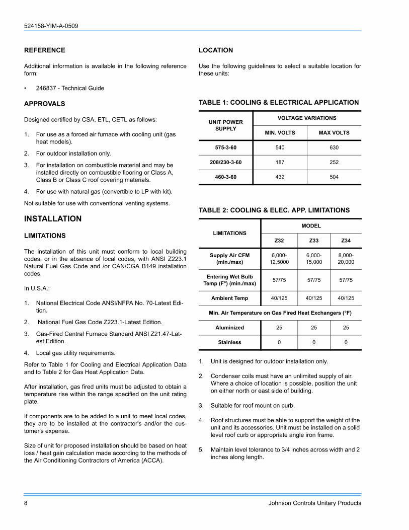
REFERENCE
Additional information is available in the following referenceform:
• 246837 - Technical Guide
APPROVALS
Designed certified by CSA, ETL, CETL as follows:
1. For use as a forced air furnace with cooling unit (gas heat models).
2. For outdoor installation only.
3. For installation on combustible material and may be installed directly on combustible flooring or Class A, Class B or Class C roof covering materials.
4. For use with natural gas (convertible to LP with kit).
Not suitable for use with conventional venting systems.
INSTALLATION
LIMITATIONS
The installation of this unit must conform to local buildingcodes, or in the absence of local codes, with ANSI Z223.1Natural Fuel Gas Code and /or CAN/CGA B149 installationcodes.
In U.S.A.:
1. National Electrical Code ANSI/NFPA No. 70-Latest Edi-tion.
2. National Fuel Gas Code Z223.1-Latest Edition.
3. Gas-Fired Central Furnace Standard ANSI Z21.47-Lat-est Edition.
4. Local gas utility requirements.
Refer to Table 1 for Cooling and Electrical Application Dataand to Table 2 for Gas Heat Application Data.
After installation, gas fired units must be adjusted to obtain atemperature rise within the range specified on the unit ratingplate.
If components are to be added to a unit to meet local codes,they are to be installed at the contractor's and/or the cus-tomer's expense.
Size of unit for proposed installation should be based on heatloss / heat gain calculation made according to the methods ofthe Air Conditioning Contractors of America (ACCA).
LOCATION
Use the following guidelines to select a suitable location forthese units:
1. Unit is designed for outdoor installation only.
2. Condenser coils must have an unlimited supply of air. Where a choice of location is possible, position the unit on either north or east side of building.
3. Suitable for roof mount on curb.
4. Roof structures must be able to support the weight of the unit and its accessories. Unit must be installed on a solid level roof curb or appropriate angle iron frame.
5. Maintain level tolerance to 3/4 inches across width and 2 inches along length.
TABLE 1: COOLING & ELECTRICAL APPLICATION
UNIT POWER SUPPLY
VOLTAGE VARIATIONS
MIN. VOLTS MAX VOLTS
575-3-60 540 630
208/230-3-60 187 252
460-3-60 432 504
TABLE 2: COOLING & ELEC. APP. LIMITATIONS
LIMITATIONSMODEL
Z32 Z33 Z34
Supply Air CFM (min./max)
6,000-12,5000
6,000-15,000
8,000-20,000
Entering Wet Bulb Temp (F°) (min./max) 57/75 57/75 57/75
Ambient Temp 40/125 40/125 40/125
Min. Air Temperature on Gas Fired Heat Exchangers (°F)
Aluminized 25 25 25
Stainless 0 0 0
524158-YIM-A-0509
Johnson Controls Unitary Products 9
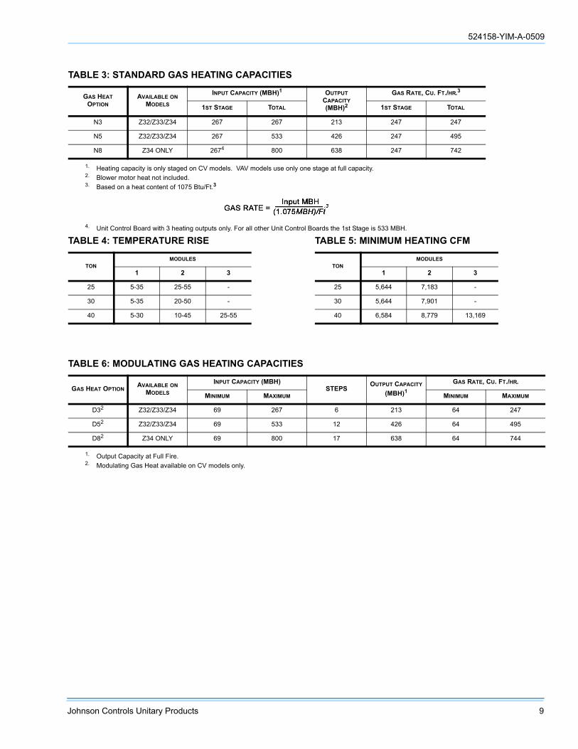
TABLE 3: STANDARD GAS HEATING CAPACITIES
GAS HEAT OPTION
AVAILABLE ON MODELS
INPUT CAPACITY (MBH)1
1. Heating capacity is only staged on CV models. VAV models use only one stage at full capacity.
OUTPUT CAPACITY (MBH)2
2. Blower motor heat not included.
GAS RATE, CU. FT./HR.3
3. Based on a heat content of 1075 Btu/Ft.3
1ST STAGE TOTAL 1ST STAGE TOTAL
N3 Z32/Z33/Z34 267 267 213 247 247
N5 Z32/Z33/Z34 267 533 426 247 495
N8 Z34 ONLY 2674
4. Unit Control Board with 3 heating outputs only. For all other Unit Control Boards the 1st Stage is 533 MBH.
800 638 247 742
TABLE 4: TEMPERATURE RISE
TONMODULES
1 2 3
25 5-35 25-55 -
30 5-35 20-50 -
40 5-30 10-45 25-55
TABLE 5: MINIMUM HEATING CFM
TONMODULES
1 2 3
25 5,644 7,183 -
30 5,644 7,901 -
40 6,584 8,779 13,169
TABLE 6: MODULATING GAS HEATING CAPACITIES
GAS HEAT OPTIONAVAILABLE ON
MODELS
INPUT CAPACITY (MBH)STEPS
OUTPUT CAPACITY (MBH)1
1. Output Capacity at Full Fire.
GAS RATE, CU. FT./HR.
MINIMUM MAXIMUM MINIMUM MAXIMUM
D32
2. Modulating Gas Heat available on CV models only.
Z32/Z33/Z34 69 267 6 213 64 247
D52 Z32/Z33/Z34 69 533 12 426 64 495
D82 Z34 ONLY 69 800 17 638 64 744

524158-YIM-A-0509
10 Johnson Controls Unitary Products
FIGURE 2 - TYPICAL RIGGING
TABLE 7: MODULATING HEAT STAGES OF GAS CONTROL (% OF FULL HEAT OUTPUT)
GAS HEAT OPTION AVAILABLE ON MODELS STEP INPUT OUTPUT % OF TOTAL OUTPUT
D3(Turn down ratio
3.8 to 1)Z32, Z33, Z34
1 69,333 55,466 26%2 106,666 85,333 40%3 165,332 132,266 62%4 202,665 162,132 76%5 229,332 183,466 86%6 266,666 213,333 100%
D5(Turn down ratio
7.7 to 1)Z32, Z33, Z34
1 69,333 55,466 13%2 106,666 85,333 20%3 165,332 132,266 31%4 202,665 162,132 38%5 229,332 183,466 43%6 266,666 213,333 50%7 325,331 260,265 61%8 362,664 290,132 68%9 389,331 311,465 73%10 426,664 341,331 80%11 495,997 396,798 93%12 533,330 426,664 100%
D8(Turn down ratio
11.5 to 1)Z34 Only
1 69,333 55,466 9%2 106,666 85,333 13%3 165,332 132,266 21%4 202,665 162,132 25%5 229,332 183,466 29%6 266,666 213,333 33%7 325,331 260,265 41%8 362,664 290,132 45%9 389,331 311,465 49%10 426,664 341,331 53%11 495,997 396,798 62%12 533,330 426,664 67%13 586,663 469,330 73%14 655,996 524,797 82%15 693,329 554,663 87%16 762,662 610,130 95%17 799,995 639,996 100%
If a unit is to be installed on a roof curb other than aYork roof curb, gasketing must be applied to all sur-faces that come in contact with the unit underside.
If a unit is to be installed on an angle iron frame it isrecommended that it be sized to allow the bottomrail to overhang to facilitate installation of conden-sate drains (see Fig. 4).
RIGGING:
(1) RIG WITH SIX CABLES AND THREE SPREADER BARS AT LEAST 98” ACROSS THE WIDTH OF THE UNIT.
(2) CENTER OF GRAVITY INCLUDES ECONOMIZER AND POWER EXHAUST.
ALL PANELS MUST BE SECURED INPLACE WHEN THE UNIT IS LIFTED.
CABLES
SPREADER BARS(3 PLACES)
27”
32”

524158-YIM-A-0509
Johnson Controls Unitary Products 11
NOTE: If the Millennium is VAV with ERV, add the weight of an exhaust VFD - it will be in the unit.
.
TABLE 8: UNIT WEIGHTSCOMPONENT 25 TON 30 TON 40 TON
Basic Unit 4410 4565 4845Gas Heat
267 MBH 180 180 180533 MBH 320 320 320800 MBH - - 450
Electric Heat40KW 40 40 4080KW 105 105 105
108KW 110 110 110Hot Water Heat
1 Row Coil 70 70 702 Row Coil 85 85 85
Steam Heat1 Row Coil 85 85 85
BlowerForward Curve Fan (Std Fan) 0 0 0
FC IGV 155 155 175Air Foil Fan 135 135 155
AF IGV 155 155 180Motor - Supply Fan
7.5hp 110 - -10hp 145 145 14515hp 200 200 20020hp 240 240 24025hp - 300 300
Supply Fan Motor VFD See Table 9Refrigeration
T-Coat Evap. 32 30 40T-Coat cond. 32 30 40
Hot Gas Bypass 10 10 10Low Ambient Head Pressure Control
208-230/380/460 5 5 5575 25 25 25
Filters6" Rigid 70 70 70
Exhaust1
1. If ERV and Supply Fan VAV are selected, add the weight of an Exhaust VFD, Table 9.
Exhaust TypeBarometric 45 65 65Modulated 140 275 275
Exhaust Motor5hp 80 80 80
7.5hp 110 110 11010hp 145 145 14515hp 200 200 200
Exhaust Motor VFD See Table 10Economizer
Std. Econ. 235 235 235Econ. w/ERV 50 50 50
ControlDisconnect 15 15 15110V outlet 55 55 55Optilogic 20 20 20
Roof CurbPartial Curb 415 415 415
TABLE 9: SUPPLY FAN MOTOR VFD WEIGHTS
Supply Fan Motor VFD 230V 460V 575V
W/O Bypass
7.5hp 60 25 30
10hp 60 25 30
15hp 75 50 60
20hp 75 50 60
25hp 115 50 60
W/Bypass
7.5hp 155 90 120
10hp 155 90 120
15hp 185 140 155
20hp 185 140 155
25hp 255 140 155
TABLE 10: EXHAUST FAN MOTOR VFD WEIGHTS
Exhaust Fan Motor 230V 460V 575V
W/O Bypass
5hp 15 10 20
7.5hp 50 15 20
10hp 50 15 20
15hp 65 40 50
FIGURE 3 - CENTER OF GRAVITY1
1. Refer to Tables 11 and 12 for A, B, C, D and X and Y data respectively.
D
RIGHT ENDCONDENSERCOILS
FRONT
CENTER OFGRAVITY
REAR
240”
92”
A
B
Y
X
C
524158-YIM-A-0509
12 Johnson Controls Unitary Products
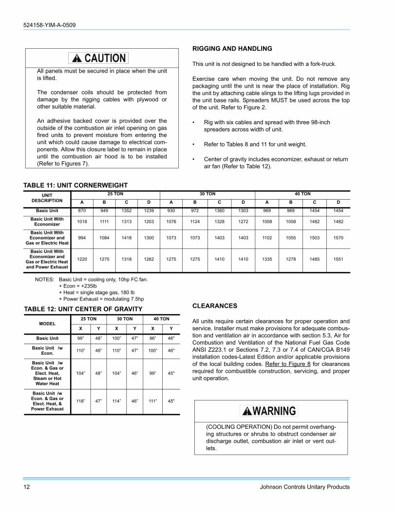
RIGGING AND HANDLING
This unit is not designed to be handled with a fork-truck.
Exercise care when moving the unit. Do not remove anypackaging until the unit is near the place of installation. Rigthe unit by attaching cable slings to the lifting lugs provided inthe unit base rails. Spreaders MUST be used across the topof the unit. Refer to Figure 2.
• Rig with six cables and spread with three 98-inch spreaders across width of unit.
• Refer to Tables 8 and 11 for unit weight.
• Center of gravity includes economizer, exhaust or return air fan (Refer to Table 12).
NOTES: Basic Unit = cooling only, 10hp FC fan.+ Econ = +235lb+ Heat = single stage gas, 180 lb+ Power Exhaust = modulating 7.5hp
CLEARANCES
All units require certain clearances for proper operation andservice. Installer must make provisions for adequate combus-tion and ventilation air in accordance with section 5.3, Air forCombustion and Ventilation of the National Fuel Gas CodeANSI Z223.1 or Sections 7.2, 7.3 or 7.4 of CAN/CGA B149installation codes-Latest Edition and/or applicable provisionsof the local building codes. Refer to Figure 8 for clearancesrequired for combustible construction, servicing, and properunit operation.
All panels must be secured in place when the unitis lifted.
The condenser coils should be protected fromdamage by the rigging cables with plywood orother suitable material.
An adhesive backed cover is provided over theoutside of the combustion air inlet opening on gasfired units to prevent moisture from entering theunit which could cause damage to electrical com-ponents. Allow this closure label to remain in placeuntil the combustion air hood is to be installed(Refer to Figures 7).
TABLE 11: UNIT CORNERWEIGHTUNIT
DESCRIPTION25 TON 30 TON 40 TON
A B C D A B C D A B C D
Basic Unit 870 949 1352 1239 930 972 1360 1303 969 969 1454 1454
Basic Unit With Economizer 1018 1111 1313 1203 1076 1124 1328 1272 1058 1058 1482 1482
Basic Unit With Economizer and
Gas or Electric Heat994 1084 1418 1300 1073 1073 1403 1403 1102 1055 1503 1570
Basic Unit With Economizer and
Gas or Electric Heat and Power Exhaust
1220 1275 1318 1262 1275 1275 1410 1410 1335 1278 1485 1551
TABLE 12: UNIT CENTER OF GRAVITY
MODEL25 TON 30 TON 40 TON
X Y X Y X Y
Basic Unit 99” 48” 100” 47” 96” 46"
Basic Unit /w Econ. 110” 48” 110” 47” 100” 46"
Basic Unit /w Econ. & Gas or
Elect. Heat, Steam or Hot Water Heat
104” 48” 104” 46” 99” 45"
Basic Unit /w Econ. & Gas or Elect. Heat, &
Power Exhaust118” 47” 114” 46” 111” 45"
(COOLING OPERATION) Do not permit overhang-ing structures or shrubs to obstruct condenser airdischarge outlet, combustion air inlet or vent out-lets.

524158-YIM-A-0509
Johnson Controls Unitary Products 13
DUCTWORK
Ductwork should be designed and sized according to themethods in Manual Q of the Air Conditioning Contractors ofAmerica (ACCA).
A closed return duct system should be used. This will not pre-clude use of economizers or outdoor fresh air intake. Thesupply and return air duct connections at the unit should bemade with flexible joints to minimize noise.
When the unit is equipped with power exhaust fans or returnair fan the return duct should have a 90 elbow before openingto the building space to abate noise.
The supply and return air duct systems should be designedfor the CFM and static pressure requirements of the job. Theyshould NOT be sized to match the dimensions of the ductconnections on the unit.
If the unit is equipped with hot water or steam heat then thesupply air direction will be down only.
AIR HOODS FOR FIXED OUTSIDE AIR(UNITS WITH MANUAL ECONOMIZER)
These hoods are factory installed. The dampers may beadjusted by loosening the thumb screw, turning the lever tothe desired position, and retightening the thumb screw.
AIR HOODS FOR ECONOMIZER
There are (3) economizer outside air intake hoods providedwith the unit. The hood on the end of the unit is factorymounted. The (2) front and rear hoods are made operationalper the following instructions.
Remove the screws holding the economizer hood shippingcovers in place. Discard covers.
Rotate the hoods out (each hood is hinged in the lower cor-ner). Secure the hoods with screws along the top and sides.
Apply a bead of RTV sealer along the edge of both hoodsand each pivot joint to prevent water leakage.
Seal any unused screw holes with RTV or by replacing thescrew.
AIR HOODS FOR EXHAUST AIR
When furnished, these hoods and dampers are factoryinstalled.
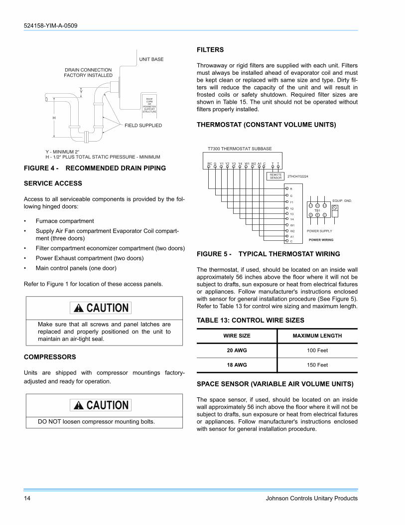
CONDENSATE DRAIN
There is one condensate drain connection. Trap the connec-tion per Figure 4. The trap and drain lines should be pro-tected from freezing.
Plumbing must conform to local codes. Use a sealing com-pound on male pipe threads. Install condensate drain linesfrom the 1-1/2 inch NPT female connections on the unit to anopen drain.
(GAS HEATING OPERATION)
Excessive exposure to contaminated combustionair will result in safety and performance relatedproblems. To maintain combustion air quality, therecommended source of combustion air is the out-door air supply.
The outdoor air supplied for combustion should befree from contaminants due to chemical exposurethat may be present from the following sources:
• Commercial buildings • Indoor pools • Laundry rooms • Hobby or craft rooms • Chemical storage areas
The following substances should be avoided tomaintain outdoor combustion air quality:
• Permanent wave solutions • Chlorinated waxes and cleaners • Chlorine based swimming pool cleaners • Water softening chemicals • De-icing salts or chemicals • Carbon tetrachloride • Halogen type refrigerants • Cleaning solvents (such as perchloroethylene) • Printing inks, paint removers, varnishes, etc. • Hydrochloric acid • Cements and glues • Antistatic fabric softeners for clothes dryers • Masonry acid washing materials
524158-YIM-A-0509
14 Johnson Controls Unitary Products
SERVICE ACCESS
Access to all serviceable components is provided by the fol-lowing hinged doors:
• Furnace compartment
• Supply Air Fan compartment Evaporator Coil compart-ment (three doors)
• Filter compartment economizer compartment (two doors)
• Power Exhaust compartment (two doors)
• Main control panels (one door)
Refer to Figure 1 for location of these access panels.
COMPRESSORS
Units are shipped with compressor mountings factory-adjusted and ready for operation.
FILTERS
Throwaway or rigid filters are supplied with each unit. Filtersmust always be installed ahead of evaporator coil and mustbe kept clean or replaced with same size and type. Dirty fil-ters will reduce the capacity of the unit and will result infrosted coils or safety shutdown. Required filter sizes areshown in Table 15. The unit should not be operated withoutfilters properly installed.
THERMOSTAT (CONSTANT VOLUME UNITS)
The thermostat, if used, should be located on an inside wallapproximately 56 inches above the floor where it will not besubject to drafts, sun exposure or heat from electrical fixturesor appliances. Follow manufacturer's instructions enclosedwith sensor for general installation procedure (See Figure 5).Refer to Table 13 for control wire sizing and maximum length.
SPACE SENSOR (VARIABLE AIR VOLUME UNITS)
The space sensor, if used, should be located on an insidewall approximately 56 inch above the floor where it will not besubject to drafts, sun exposure or heat from electrical fixturesor appliances. Follow manufacturer's instructions enclosedwith sensor for general installation procedure.
FIGURE 4 - RECOMMENDED DRAIN PIPING
Make sure that all screws and panel latches arereplaced and properly positioned on the unit tomaintain an air-tight seal.
DO NOT loosen compressor mounting bolts.
� � � � � � � � � � � � � � � � � � � � � � � � � � � � � � � � � � � � �� � � � � � � � � � � � � �
�
� � � � � � � � � �
� � � � � � � � � � � � � � �� � � � � � � � � � � � �
� � � � � � � �
�
� � � �� � � �� �
� � � � � � � � � � �
� � � � � � �
FIGURE 5 - TYPICAL THERMOSTAT WIRING
TABLE 13: CONTROL WIRE SIZES
WIRE SIZE MAXIMUM LENGTH
20 AWG 100 Feet
18 AWG 150 Feet
� � � � � � � � � � � � � � � � � � � � � � � � � � � � � � � � � � � � � � � � � � � � � � � � � � � � � �
�
�
� �
� �
� �
� �
� �
� �
� �
�
� � � � � � � � � � � � � � � � � �
� � � � � � � � � � � � � � � � � � �
� � � � � �
� � �
� � �
� � � � � � � � �
� � � � � � � � � �
� � � � � � � � � �

524158-YIM-A-0509
Johnson Controls Unitary Products 15
POWER AND CONTROL WIRING
Field wiring to the unit must conform to provisions of NationalElectrical Code (NEC) ANSI / NFPA 70-Latest Edition and / orlocal ordinances. The unit must be electrically grounded inaccordance with the NEC and / or local codes. Voltage toler-ances which must be maintained at the compressor terminalsduring starting and running conditions are indicated on theunit Rating Plate and Table 1.
The internal wiring harnesses furnished with this unit are anintegral part of the design certified unit. Field alteration tocomply with electrical codes should not be required. If any ofthe wire supplied with the unit must be replaced, replacementwire must be of the type shown on the wiring diagram and thesame minimum gauge as the replaced wire.
Power supply to the unit must be NEC Class 1 and mustcomply with all applicable codes. A disconnect switch mustbe provided (factory option available). The switch must beseparate from all other circuits. Wire entry at knockout open-ings requires conduit fittings to comply with NEC and/or LocalCodes. Refer to Figures 11, 12, 13, and 14 for installationlocation of openings.
If installing a field mounted disconnect on the unit, refer toFigure 15 for the recommended mounting location.Unitstrut™ or equivalent rails should be mounted as shown toprovide structure for mounting. The location of the railsshould be adjusted to fit the disconnect within the dimensionsshown. Conduit run from the disconnect to the power entrylocation in the baserail should be routed so that it does notinterfere with the doors of the unit access panels.
NOTE: Since not all local codes allow mounting a discon-nect on the unit, please confirm compliance withlocal code before mounting a disconnect on the unit.
Electrical wiring must be sized properly to carry the load.Each unit must be wired with a separate branch circuit feddirectly from the meter panel and properly fused.
Refer to Figure 5 for typical field wiring and to the appropriateunit wiring diagram mounted inside control doors for controlcircuit and power wiring information.
POWER WIRING DETAIL
Units are factory wired for the voltage shown on the unitnameplate. The main power block requires copper wires.Refer to Electrical Data Tables 17 through 28 to size powerwiring, fuses and disconnect switch. All field supplied wiring,fuses and disconnects must comply with applicable NECcodes.
Power wiring is brought into the unit through the side of thebaserail or the bottom of the unit/control box inside the curb.The baserail has a 2-1/2” diameter hole for field wiring and a3-5/8” hole is provided for a through-the-curb connection. Aremovable patch plate covers both the openings.
ERV
The ERV [Energy Recovery Ventilation] is a separate air han-dler that attaches to the exhaust end of the 25-40T Millen-nium packaged rooftop unit. The ERV is shipped separatelyand assembled to the Millennium at the jobsite. An 'ERV' Mil-lennium is shipped with an end configuration and electrichookups designed to mate with the ERV. This option is avail-able only with the Simplicity® control, and no other powerexhaust option can be supplied if an ERV is selected.
The ERV incorporates a rotating heat exchange wheel and apair of exhaust blowers. It exhausts return air through thewheel, capturing the thermal energy of the exiting hot or coldair as it passes. As the wheel rotates, the incoming airstream,pulled through by the supply fan, regains that energy.
The Millennium ERV has a terminal block and mating con-nectors to simplify hooking up the two systems. The controlsof both units are factory set to interact properly. Power for theERV blower motors and controls is provided through the Mil-lennium unit. The Millennium /ERV dataplate informationincludes the ERV electrical load.
The Millennium Simplicity® control has parameters for theERV; refer to the parameter list. When economizer and ERVoptions are selected on the same unit, the Simplicity® controland the ERV have specific connections and internal rules forthat operation.
Also refer to the ERV Installation Instructions packaged withthe ERV.
Use care to avoid damage when drilling holes forthe disconnect mounting.
When connecting electrical power and control wir-ing to the unit, waterproof connectors MUST BEUSED so that water or moisture cannot be drawninto the unit during normal operation. The abovewaterproofing conditions will also apply wheninstalling a field-supplied disconnect switch.
Waterproof connections MUST be used to ensurethat water cannot penetrate the roof or roof curb.

524158-YIM-A-0509
16 Johnson Controls Unitary Products
GAS HEATING
GAS PIPING
Proper sizing of gas piping depends on the cubic feet perhour of gas flow required, specific gravity of the gas and thelength of run. National Fuel Gas Code Z223.1-Latest Editionshould be followed in all cases unless superseded by localcodes or gas company requirements. Refer to Table 14.
The heating value of the gas may differ with locality. Thevalue should be checked with the local gas utility.
NOTE: There may be a local gas utility requirement specify-ing a minimum diameter for gas piping. All unitsrequire a 1-1/4 inch pipe connection at the entrancefitting. Line should not be sized smaller than theentrance fitting size.
GAS CONNECTION
The gas supply line should be routed within the space andpenetrate the roof at the gas inlet connection of the unit.Refer to Figures 11 through 14 to locate the access opening.Typical supply piping arrangements are shown in Figure 6.
Gas piping recommendations:
1. A drip leg and a ground joint union must be installed in the gas piping.
2. When required by local codes, a manual shut-off valve will have to be installed outside of the unit.
3. Use wrought iron or steel pipe for all gas lines. Pipe dope should be applied sparingly to male threads only.
4. All piping should be cleaned of dirt and scale by ham-mering on the outside of the pipe and blowing out the loose particles. Before initial start-up, be sure that all of the gas lines external to the unit have been purged of air.
5. The gas supply should be a separate line and installed in accordance with all safety codes as prescribed under Limitations. After the gas connections have been com-pleted, open the main shutoff valve admitting normal gas pressure to the mains. Check all joints for leaks with soap solution or other material suitable for the purpose. NEVER USE A FLAME.
6. The furnace and its individual manual shut-off valve must be disconnected from the gas supply piping system dur-ing any pressure testing of that system at test pressures in excess of 0.5 psig.
On VAV units with gas fired furnace, ALL INDIVID-UAL ROOM DAMPER BOXES MUST BE CON-TROLLED FULL OPEN DURING HEATINGOPERATION TO ENSURE PROPER AIRFLOWOVER THE FURNACE. A control contact poweredby the “VAV OPEN” terminals on the Simplicity®control is provided for the damper box interlock.this contact is normally open, and is closed duringheating operation.
TABLE 14: PIPE SIZES
LENGTH IN FEET
NOMINAL IRON PIPE, SIZE
1-1/4 IN.1
1. Maximum capacity of pipe in cubic feet of gas per hour (based upon a pressure drop of 0.3 inch water column and 0.6 specific gravity gas.
1-1/2 IN.1 2 IN.1
10 1,050 1,600 3,05020 730 1,100 2,10030 590 890 1,65040 - 760 1,45050 - - 1,27060 - - 1,15070 - - 1,05080 - - 990
FIGURE 6 - TYPICAL GAS PIPING CONNECTION
Natural gas may contain some propane. Propane,is an excellent solvent and will quickly dissolvewhite lead or most standard commercial pipe seal-ing compounds. Therefore, special shellac basepipe dope compounds such as Gaskolac or Stalas-tic, and compounds such as Rectorseal #5,Clyde’s or John Crane must be applied for wroughtiron or steel pipe.

524158-YIM-A-0509
Johnson Controls Unitary Products 17
7. A 1/8 inch N.P.T. plugged tapping, accessible for test gage connection, must be installed immediately upstream of the gas supply connection to the furnace.
VENT AND COMBUSTION AIR
NOTE: All the hoods and hardware are shipped within theevaporator section. Each hood must be properlyattached to the furnace doors to assure properoperation and compliance with CSA/ETL safety cer-tification. (Refer to Figure 7.)
The products of combustion are discharged horizontallythrough hooded openings in the gas heat access doors.
(Figure 7)
1. Remove the shipping covers that are attached to the heat section door covering the flue outlets.
2. Locate the flue which is shipped in the evaporator sec-tion.
3. Place the flue over the flue outlet and attach with screws provided.
4. Refer to the Gas Furnace Operation Instruction in the Start-up Section of this manual for further instructions.
Disconnect gas piping from unit when leak testingat pressures greater than 0.5 psig. Pressuresgreater than 0.5 psig will cause gas valve damageresulting in a hazardous condition. If gas valve issubjected to pressure greater than 0.5 psig, it mustbe replaced.
FIGURE 7 - VENT AND COMBUSTION AIR HOODS
COMBUSTIONAIR INLET
REMOVE SHIPPINGLABELS PRIOR TOVENT INSTALLATION
HEAT SECTION DOOR
VENT FLUEASSEMBLY
EXHAUST VENT OUTLET
FIGURE 8 - CLEARANCES
60"REAR
60"FRONT
60"ENDS
10'
60"ENDS
REQUIRED CLEARANCES
LEFTRIGHTREARFRONTTOP
60"60"60"60"10'
* Right is the side with access to the Electrical / Gas Controls.* is the side with the Condenser Coils
NOTE: DONOT use the unit roof to support any type ofstructure or bracing.
Front

524158-YIM-A-0509
18 Johnson Controls Unitary Products
ELECTRIC HEAT
Units with electric heat are fully wired and operational whenshipped. Constant volume units are designed for two equalsteps of capacity for 80 and three for 108 kWH heat; 40 kWheat is one step only. Heat outputs on VAV units are all turnedon together at full heat capacity.
HOT WATER HEAT
The YORK Millennium units (25, 30, and 40 Ton sizes) can befurnished with a YORK hot water coil as the heat source. Oneor two row coil units will be factory installed in the heatingsection.
NOTE: The hot water control valve will not be provided. Theinstaller will need to provide a hot water controlvalve, to connect the hot water piping and powerwiring at the job site for the hot water heat section tobe operational.
NOTE: For all hot water coils the entering water tempera-ture should not exceed 200°F.
The hot water coil is located downstream of the supply air fanand just above the supply air opening in the bottom of theunit.
Refer to Tables 50 through 58 and Figures 27 through 40 forflow rate and capacity.
PIPING CONNECTIONS
The hot water piping must enter the unit through the floor ofthe heat section compartment. The access doors to the com-partment are gasketed so the compartment can be sealed.However, as added protection for water leakage into thespace, the piping access holes should be sealed with a heatresistant mastic Figure 9 shows the location of the compart-ment and piping connections.
DO NOT use hot water coils as steam coils underany circumstances.
All piping, control valves, and wiring that is fieldinstalled must be properly insulated and conformto all local and national codes.
There are no provisions in the coil or controlsequence to prevent freezing of condensate. Thecontrol valve, piping and field installed wiring con-nections are particularly vulnerable because theyare installed in the vestibule outside of the condi-tioned air stream. The installing party will beresponsible for properly insulating and installingpower and control wiring, to the actuator and pip-ing.
In one row hot water coil systems DO NOT exceeda 40 gallons per minute flow rate.
In two row hot water coil systems DO NOT exceedan 80 gallons per minute flow rate.
Condensate will freeze on the control valve andpiping if they are not properly insulated. Insulatingthe control valve and piping is the responsibility ofthe installing party.
Piping access holes should be sealed with a heatresistant mastic to prevent damage to equipment.

524158-YIM-A-0509
Johnson Controls Unitary Products 19
STEAM HEAT
The YORK Millennium units (25, 30 and 40 Ton sizes) can befurnished with a YORK single row steam coil. YORK steamcoils are a factory installed option.
NOTE: The steam control valve, power and control wiring tothe actuator of the valve is the responsibility of theinstalling party.
PIPING CONNECTIONS
Refer to Tables 46 through 49 and Figures 41 and 42 for flowrate and capacity.
The steam piping must enter the unit through the floor of theheat section compartment. The access doors to the compart-ment are gasketed so the compartment can be sealed. How-ever, as added protection for condensate leakage into thespace, the piping access holes should be sealed with a heatresistant mastic. The following figure illustrates the location ofthe compartment and piping connections.
DO NOT use tin based solder. Brazing with tinbased solder could cause equipment damage orpossible injury to tenants of the structure that isbeing conditioned.
FIGURE 9 - HOT WATER PIPING CROSS-SEC-TION
FIGURE 10 - STEAM PIPING CROSS-SECTION
� � � � � � � �� � �
� � � � � � � � � � �
� � � � � � !� � � � � � � � !
� �
� � " "
# � � #
� � � "
� � � # #
� $
� " � #
# # � � "
� � � � � � � �� � � � � � � � � �
� � � � � � � � � � �
� � � � � � �� � � � � �
� � �� � �
� � � � � � � � � � �
� � � � � � � � � � % � !
� �
� � " "
# � � #
� $
� " � # � � � � � � !
#
&
� � � � � � � �� � � � � � � � � �
# # � � "
� � � � � � � �
� � � � � � �� � � � � �
All piping and control valves, and wiring that isfield installed must be properly insulated and con-form to all local and national codes.
There are no provisions in the coil or controlsequence to prevent freezing of condensate. Thecontrol valve, piping and field installed wiring con-nections are particularly vulnerable because theyare installed in the vestibule outside of the condi-tioned air stream. The installing party will beresponsible for properly insulating and installingpower and control wiring, to the actuator and pip-ing.
DO NOT use steam coils as hot water coils underany circumstances.
In steam coil systems, the steam pressure shallnot exceed 15 PSI.
Piping access holes should be sealed with a heatresistant mastic to prevent damage to equipment.
DO NOT use tin based solder. Brazing with tinbased solder could cause equipment damage orpossible injury to tenants of the structure that isbeing conditioned.
524158-YIM-A-0509
20 Johnson Controls Unitary Products
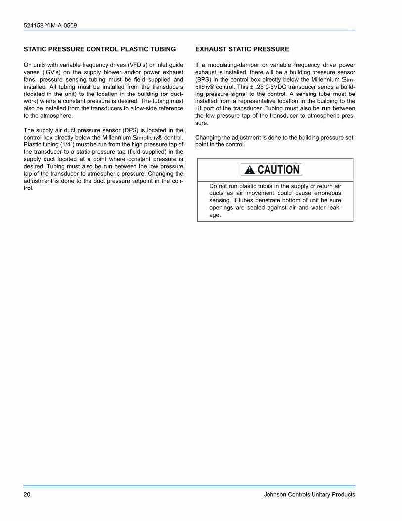
STATIC PRESSURE CONTROL PLASTIC TUBING
On units with variable frequency drives (VFD’s) or inlet guidevanes (IGV's) on the supply blower and/or power exhaustfans, pressure sensing tubing must be field supplied andinstalled. All tubing must be installed from the transducers(located in the unit) to the location in the building (or duct-work) where a constant pressure is desired. The tubing mustalso be installed from the transducers to a low-side referenceto the atmosphere.
The supply air duct pressure sensor (DPS) is located in thecontrol box directly below the Millennium Simplicity® control.Plastic tubing (1/4”) must be run from the high pressure tap ofthe transducer to a static pressure tap (field supplied) in thesupply duct located at a point where constant pressure isdesired. Tubing must also be run between the low pressuretap of the transducer to atmospheric pressure. Changing theadjustment is done to the duct pressure setpoint in the con-trol.
EXHAUST STATIC PRESSURE
If a modulating-damper or variable frequency drive powerexhaust is installed, there will be a building pressure sensor(BPS) in the control box directly below the Millennium Sim-plicity® control. This ± .25 0-5VDC transducer sends a build-ing pressure signal to the control. A sensing tube must beinstalled from a representative location in the building to theHI port of the transducer. Tubing must also be run betweenthe low pressure tap of the transducer to atmospheric pres-sure.
Changing the adjustment is done to the building pressure set-point in the control.
Do not run plastic tubes in the supply or return airducts as air movement could cause erroneoussensing. If tubes penetrate bottom of unit be sureopenings are sealed against air and water leak-age.

524158-YIM-A-0509
Johnson Controls Unitary Products 21
FIGURE 11 - BOTTOM SUPPLY AND RETURN
88.7"
CLCL240"
38.59"83"
4.5"
4.5"
64"
92"
80.93"SEE
DETAILA
26"
4.5"
15.89"
71.61"
127.5"
100.10"
128.50"
SEEDETAIL
CSEE
DETAILB
OPEN3.625"
6.46"
12"MIN
SUPPLY AIR
RETURN AIR
REAR
REAR
LEFTEND
LEFTEND
RIGHT END
RIGHT END
FRONT
FRONT
3-1/16"
1-1/4" FPT
3-5/8"
6.46"
BASE RAIL
DETAIL B(ELECTRICAL CONNECTION)
FOR COOLING ONLY AND ALL HEATING APPLICATIONS
28”
2-1/2”DIA. HOLES
TO GAS VALVEMANIFOLD
7”
1-1/4” NPT
11”
DETAIL C(GAS CONNECTIONTHROUGH CURB)
1-1/2" FP T
DETAIL A(DRAIN CONNECTION)
BASE RAIL
4-5/8”

524158-YIM-A-0509
22 Johnson Controls Unitary Products
FIGURE 12 - END RETURN, BOTTOM SUPPLY
RETURN AIR
SUPPLY AIR
1-1/2" FPT
3-1/16"
3-5/8"
6.46"
2-1/2"
NOTE:FACTORY INSTALLED POWEREXHAUST CANNOT BE ORDEREDWITH END RETURN.
DETAIL A(DRAIN CONNECTION)
DETAIL B(ELECTRICAL CONNECTION)
FOR COOLING ONLY AND ALL HEATING APPLICATIONS
BASE RAIL
BASE RAIL
28”
2-1/2”DIA. HOLES
TO GAS VALVEMANIFOLD
7”
1-1/4” NPT
11”
DETAIL C(GAS CONNECTIONTHROUGH CURB)
4-5/8”
240"
64"
92"
80.93"SEE
DETAILA
100.10"
128.50"
SEEDETAIL
B
75.6"
OPEN
7-7/8"
8.15"76-3/824.9"
6.25"
26"
4.5"
15.89"
71.61"
SEEDETAIL
C
3.625"
6.46"
12"MIN
CL 88.7"
REAR
RIGHT END
LEFT END FRONT
FRONT
RIGHT END
LEFT END
REAR

524158-YIM-A-0509
Johnson Controls Unitary Products 23
FIGURE 13 - BOTTOM RETURN, FRONT & REAR SUPPLY
1-1/2" FPT
3-1/16"
3-5/8"
6.46"
2-1/2"
DETAIL A(DRAIN CONNECTION)
DETAIL B(ELECTRICAL CONNECTION)
FOR COOLING ONLY AND ALL HEATING APPLICATIONS
BASE RAIL
BASE RAIL
28”
2-1/2”DIA. HOLES
TO GAS VALVEMANIFOLD
7”
1-1/4” NPT
11”
DETAIL C(GAS CONNECTIONTHROUGH CURB)
4-5/8”
FRONT SUPPLY: FOR COOLING ONLY APPLICATIONSREAR SUPPLY: FOR COOLING ONLY OR GAS HEAT APPLICATIONS
RETURN AIR
SUPPLY AIR
240"
38.59"83"
4.5"
4.5"
64"
92"
80.93" SEEDETAIL
A
100.10"
128.50"
SEEDETAIL
C
SEEDETAIL
B
26"
55"
75.6"
OPEN
8.15"
3.625"
6.46"
12"MIN
FRONT
FRONT
FRONT
REAR
REAR
LEFT END
LEFT END
REAR
RIGHT END
RIGHT END
524158-YIM-A-0509
24 Johnson Controls Unitary Products
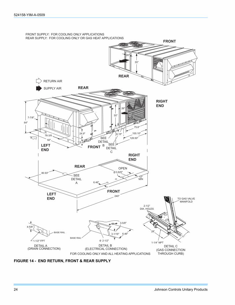
FIGURE 14 - END RETURN, FRONT & REAR SUPPLY
FRONT SUPPLY: FOR COOLING ONLY APPLICATIONS REAR SUPPLY: FOR COOLING ONLY OR GAS HEAT APPLICATIONS
RETURN AIR
SUPPLY AIR
2 4 0 "
6 4 "
9 2 "
8 0 . 9 3 " SEE
DETAIL A
1 0 0 . 1 0 "
1 2 8 . 5 0 "
SEE DETAIL
C
SEE DETAIL
B
2 6 "
5 5 "
7 5 . 6 "
OPEN
7 - 7 / 8 "
8 . 1 5 " 2 4 . 9 "
6 . 2 5 "
3 . 6 2 5 "
6 . 4 6 "
1 2 " M I N
7 6 - 3 / 8
2 6 "
5 5 "
RIGHT END
RIGHT END
LEFT END
LEFT END
REAR
REAR
REAR
FRONT
FRONT
1-1/2" FPT
3-1/16"
3-5/8"
6.46"
2-1/2"
DETAIL A(DRAIN CONNECTION)
DETAIL B(ELECTRICAL CONNECTION)
FOR COOLING ONLY AND ALL HEATING APPLICATIONS
BASE RAIL
BASE RAIL
28”
2-1/2”DIA. HOLES
TO GAS VALVEMANIFOLD
7”
1-1/4” NPT
11”
DETAIL C(GAS CONNECTIONTHROUGH CURB)
4-5/8”
FRONT

524158-YIM-A-0509
Johnson Controls Unitary Products 25
* Unit Control Board with 3 heating outputs only, all other Unit Control Boards 2 / 1.
TABLE 15: GENERAL PHYSICAL DATAUNIT SIZE 25 TON 30 TON 40 TON
UNIT EER / IPLV(STANDARD CAPACITY EVAPORATOR) 10.5 / 12.3 10.5 / 11.0 10.5 / 11.2
COMPRESSOR DATA
NUMBER/SIZE 4 x 5.7Ton 4 x 7 Ton 4 x 8.6 TonTYPE Scroll Scroll Scroll
UNIT CAPACITY STEPS 25%, 50%, 75%, 100% 25%, 50%, 75%, 100% 25%, 50%, 75%, 100%INDOOR FAN AND DRIVE
NUMBER / TYPE 1 / FC 1 / FC 1 / FCDIAMETER X WIDTH (INCHES) 22 x20 22 x 20 25 x 22
HP RANGE 7.5 - 20 10 - 25 10 - 25CFM RANGE (FULL LOAD) 6,000 - 12,500 6,000 - 15,000 8,000 - 18,000
ESP RANGE 0.2” - 4.0” 0.2" - 4.0” 0.2" - 4.0"EXHAUST FAN
NUMBER/SIZE/TYPE 1/FC 2/FC 2/FCHP RANGE (SINGLE MOTOR) 5 - 10 7.5 - 15 7.5 - 15
CFM 3,000 - 9,000 4,000 - 15,000 4,000 - 18,000EVAPORATOR COIL
SIZE (SQ. FT.) 26.0 26.0 30.4ROWS/FPI 3 / 16 4 / 16 4 / 16
CONDENSER COIL
SIZE (SQ. FT.) 65 78 104ROWS/FPI 2/16 2 /16 2 /16
CONDENSER FANS
QUANTITY / DIAMETER (INCHES) 4 / 24 4 / 24 4 / 30NOMINAL CFM 6,800 7,200 9,600
MOTOR HP 1.0 1.5 1.5ELECTRIC HEAT
KW RANGE 40 - 108 40 - 108 40 - 10840 KW / CAPACITY STEPS (CV/VAV) 1 1 180 KW / CAPACITY STEPS (CV/VAV) 2 / 1 2 / 1 2 / 1108 KW / CAPACITY STEPS (CV/VAV) 3 / 1* 3 / 1* 3 / 1*
NATURAL GAS HEAT
UNIT SIZE 25 TON 30 TON 40 TON267 MBH CAPACITY STEPS (CV/VAV) 1 / 1 1 / 1 1 / 1533 MBH CAPACITY STEPS (CV/VAV) 2 / 1 2 / 1 2 / 1800 MBH CAPACITY STEPS (CV/VAV) - - 3 / 1*
267 MBH “MODULATING” CAPACITY STEPS (CV ONLY) 6 / 1 6 / 1 6 / 1533 MBH “MODULATING” CAPACITY STEPS (CV ONLY) 12 / 2 12 / 2 12 / 2800 MBH “MODULATING” CAPACITY STEPS (CV ONLY) - - 17 / 3
HOT WATER COIL
SIZE (INCHES) 22.5” x 65” 22.5" X 65” 22.5" X 65”CAPACITY 25 Ton 30 Ton 40 Ton
STEAM COIL
SIZE (INCHES) 21" X 65"TYPE Steam Coil
FILTERS 2" TA NUMBER / SIZE 4 / 16 x 25 & 6 / 20 x 25 4 / 16 x 25 & 6 / 20 x 25 4 / 16 x 25 & 6 / 20 x 25
FACE AREA (SQ. FT.) 30.4 30.4 30.4FILTERS 2" PLEATED, 30%
NUMBER / SIZE 4 / 16 x 25 & 6 / 20 x 25 4 / 16 x 25 & 6 / 20 x 25 4 / 16 x 25 & 6 / 20 x 25FACE AREA (SQ. FT.) 30.4 30.4 30.4
FILTERS 65% RIGID W/ 2” TA PREFILTERS
NUMBER / SIZE 4 / 16 x 25 & 6 / 20 x 25 4 /16 x 25 & 6 / 20 x 25 4 / 16 x 25 & 6 / 20 x 25FACE AREA (SQ. FT.) 30.4 30.4 30.4
FILTERS 95% RIGID W/ 2” TA PREFILTERS
NUMBER / SIZE 4 ea. 16 x 25 / 6 ea. 20 x 25 4 ea. 16 x 25 / 6 ea. 20 x 25 4 ea. 16 x 25 / 6 ea. 20 x 25FACE AREA (SQ. FT.) 30.4 30.4 30.4

524158-YIM-A-0509
26 Johnson Controls Unitary Products
TABLE 16: REFRIGERANT FACTORY CHARGE R-410A
UNIT (TONS) MODELCHARGE
SYSTEM #1 SYSTEM #2 SYSTEM #3 SYSTEM #4
25 wo/HGBP 12lb 6oz 12lb 9oz 10lb 9oz 10lb 14oz
25 w/HGBP 12lb 14oz 13lb 1oz 11lb 1oz 11lb 6oz
30 wo/HGBP 16lb 16lb 8oz 14lb 18lb 4oz
30 w/HGBP 16lb 8oz 17lb 14lb 8oz 18lb 12oz
40 wo/HGBP 17lb 10oz 17lb 10oz 19lb 13oz 19lb 13oz
40 w/HGBP 18lb 2oz 18lb 2oz 20lb 5oz 20lb 5oz
TABLE 17: ELECTRICAL DATA 25 TON BASIC UNIT R-410A
VoltageCompressors (each) OD Fan Motors Supply Blower
Motor MCA1
(Amps)
Max Fuse2/Breaker3
Size(Amps)
Qty RLA LRA MCC Qty FLA HP FLA
208-3-60 4 23.0 160 36.0 4 4.5
7.5 24.2 140 15010 30.8 149 17515 46.2 168 20020 59.4 184 225
230-3-60 4 23.0 160 36.0 4 4.3
7.5 22.0 137 15010 28.0 144 15015 42.0 162 20020 54.0 177 225
460-3-60 4 12.2 87 19.0 4 2.2
7.5 11.0 72 8010 14.0 75 8015 21.0 84 10020 27.0 91 110
575-3-60 4 8.6 62 13.5 4 1.7
7.5 9.0 52 6010 11.0 55 6015 17.0 62 7020 22.0 69 90
1. Minimum Circuit Ampacity.2. Dual Element, Time Delay Type.3. HACR type per NEC.

524158-YIM-A-0509
Johnson Controls Unitary Products 27
TABLE 18: ELECTRICAL DATA 30 TON BASIC UNIT R-410A
VoltageCompressors (each) OD Fan Motors Supply Blower
Motor MCA1
(Amps)
Max Fuse2/Breaker3
Size(Amps)
Qty RLA LRA MCC Qty FLA HP FLA
208-3-60 4 25.0 164 39.0 4 5.8
10 30.8 162 17515 46.2 181 22520 59.4 197 25025 74.8 217 250
230-3-60 4 25.0 164 39.0 4 5.2
10 28.0 156 17515 42.0 173 20020 54.0 188 22525 68.0 206 250
460-3-60 4 12.2 100 19.0 4 2.6
10 14.0 78 9015 21.0 87 10020 27.0 94 11025 34.0 103 125
575-3-60 4 9.0 78 14.0 4 2.2
10 11.0 59 6015 17.0 66 8020 22.0 72 9025 27.0 79 100
1. Minimum Circuit Ampacity.2. Dual Element, Time Delay Type.3. HACR type per NEC.
TABLE 19: ELECTRICAL DATA 40 TON BASIC UNIT R-410A
VoltageCompressors (each) OD Fan Motors Supply Blower
Motor MCA1
(Amps)
Max Fuse2/Breaker3
Size(Amps)
Qty RLA LRA MCC Qty FLA HP FLA
208-3-60 4 30.1 225 47.0 4 5.8
10 30.8 182 20015 46.2 201 22520 59.4 218 25025 74.8 237 300
230-3-60 4 30.1 225 47.0 4 5.2
10 28.0 177 20015 42.0 194 22520 54.0 209 25025 68.0 228 250
460-3-60 4 16.7 114 26.0 4 2.6
10 14.0 98 11015 21.0 105 12520 27.0 112 12525 34.0 121 150
575-3-60 4 12.2 80 19.0 4 2.2
10 11.0 72 8015 17.0 79 9020 22.0 85 10025 27.0 91 110
1. Minimum Circuit Ampacity.2. Dual Element, Time Delay Type.3. HACR type per NEC.

524158-YIM-A-0509
28 Johnson Controls Unitary Products
TABLE 20: ELECTRICAL DATA 25 TON W/ELECTRIC HEAT R-410A
VoltageCompressors
(each)OD Fan Motors(each)
Supply BlowerMotor Electric Heat Option MCA1
(Amps)
Max Fuse2/Breaker3
Size(Amps)Qty RLA LRA MCC FLA HP FLA Option KW Applied Stages Amps
208-3-60 4 23.0 160 36.0 4.5
7.5 24.2 E4 40 30 1 83.4 140 15010 30.8 E4 40 30 1 83.4 149 17515 46.2 E4 40 30 1 83.4 168 20020 59.4 E4 40 30 1 83.4 184 2257.5 24.2 E8 80 60 2 166.8 197 22510 30.8 E8 80 60 2 166.8 205 22515 46.2 E8 80 60 2 166.8 225 25020 59.4 E8 80 60 2 166.8 241 300
230-3-60 4 23.0 160 36.0 4.3
7.5 22.0 E4 40 36.8 1 92.2 148 15010 28.0 E4 40 36.8 1 92.2 155 17515 42.0 E4 40 36.8 1 92.2 173 20020 54.0 E4 40 36.8 1 92.2 188 2257.5 22.0 E8 80 73.6 2 184.4 220 25010 28.0 E8 80 73.6 2 184.4 227 25015 42.0 E8 80 73.6 2 184.4 245 25020 54.0 E8 80 73.6 2 184.4 260 300
460-3-60 4 12.2 87 19.0 2.2
7.5 11.0 E4 40 36.8 1 46.1 76 8010 14.0 E4 40 36.8 1 46.1 80 9015 21.0 E4 40 36.8 1 46.1 89 10020 27.0 E4 40 36.8 1 46.1 96 1107.5 11.0 E8 80 73.6 2 92.2 110 12510 14.0 E8 80 73.6 2 92.2 114 12515 21.0 E8 80 73.6 2 92.2 122 12520 27.0 E8 80 73.6 2 92.2 130 1507.5 11.0 E1 108 99.4 3 124.5 144 17510 14.0 E1 108 99.4 3 124.5 147 17515 21.0 E1 108 99.4 3 124.5 156 17520 27.0 E1 108 99.4 3 124.5 164 175
575-3-60 4 8.6 62 13.5 1.7
7.5 9.0 E4 40 36.8 1 40.2 59 6010 11.0 E4 40 36.8 1 40.2 62 7015 17.0 E4 40 36.8 1 40.2 69 7020 22.0 E4 40 36.8 1 40.2 78 907.5 9.0 E8 80 73.6 2 80.3 88 10010 11.0 E8 80 73.6 2 80.3 91 10015 17.0 E8 80 73.6 2 80.3 98 11020 22.0 E8 80 73.6 2 80.3 104 1257.5 9.0 E1 108 99.4 3 108.4 115 12510 11.0 E1 108 99.4 3 108.4 118 15015 17.0 E1 108 99.4 3 108.4 125 15020 22.0 E1 108 99.4 3 108.4 136 150
1. Minimum Circuit Ampacity.2. Dual Element, Time Delay Type.3. HACR type per NEC.

524158-YIM-A-0509
Johnson Controls Unitary Products 29
TABLE 21: ELECTRICAL DATA 30 TON W/ELECTRIC HEAT R-410A
VoltageCompressors
(each)OD Fan Motors(each)
Supply BlowerMotor Electric Heat Option MCA1
(Amps)
Max Fuse2/Breaker3
Size(Amps)Qty RLA LRA MCC FLA HP FLA Option KW Applied Stages Amps
208-3-60 4 25.0 164 39.0 5.8
10 30.8 E4 40 30 1 83 162 17515 46.2 E4 40 30 1 83 181 22520 59.4 E4 40 30 1 83 197 25025 74.8 E4 40 30 1 83 217 25010 30.8 E8 80 60 2 167 205 22515 46.2 E8 80 60 2 167 225 25020 59.4 E8 80 60 2 167 241 30025 74.8 E8 80 60 2 167 260 300
230-3-60 4 25.0 164 39.0 5.2
10 28.0 E4 40 36.8 1 92 156 17515 42.0 E4 40 36.8 1 92 173 20020 54.0 E4 40 36.8 1 92 188 22525 68.0 E4 40 36.8 1 92 206 25010 28.0 E8 80 73.6 2 184 227 25015 42.0 E8 80 73.6 2 184 245 25020 54.0 E8 80 73.6 2 184 260 30025 68.0 E8 80 73.6 2 184 277 300
460-3-60 4 12.2 100 19.0 2.6
10 14.0 E4 40 36.8 1 46 78 9015 21.0 E4 40 36.8 1 46 87 10020 27.0 E4 40 36.8 1 46 94 11025 34.0 E4 40 36.8 1 46 103 12510 14.0 E8 80 73.6 2 92 114 12515 21.0 E8 80 73.6 2 92 122 12520 27.0 E8 80 73.6 2 92 130 15025 34.0 E8 80 73.6 2 92 139 15010 14.0 E1 108 99.4 3 125 147 17515 21.0 E1 108 99.4 3 125 156 17520 27.0 E1 108 99.4 3 125 164 17525 34.0 E1 108 99.4 3 125 172 200
575-3-60 4 9.0 78 14.0 2.2
10 11.0 E4 40 36.8 1 40 62 7015 17.0 E4 40 36.8 1 40 69 8020 22.0 E4 40 36.8 1 40 76 9025 27.0 E4 40 36.8 1 40 82 10010 11.0 E8 80 73.6 2 80 91 10015 17.0 E8 80 73.6 2 80 98 11020 22.0 E8 80 73.6 2 80 104 12525 27.0 E8 80 73.6 2 80 111 12510 11.0 E1 108 99.4 3 108 118 15015 17.0 E1 108 99.4 3 108 129 15020 22.0 E1 108 99.4 3 108 131 15025 27.0 E1 108 99.4 3 108 142 150
1. Minimum Circuit Ampacity.2. Dual Element, Time Delay Type.3. HACR type per NEC.

524158-YIM-A-0509
30 Johnson Controls Unitary Products
TABLE 22: ELECTRICAL DATA 40 TON W/ELECTRIC HEAT R-410A
VoltageCompressors
(each)OD Fan Motors(each)
Supply BlowerMotor Electric Heat Option MCA1
(Amps)
Max Fuse2/Breaker3
Size(Amps)Qty RLA LRA MCC FLA HP FLA Option KW Applied Stages Amps
208-3-60 4 30.1 225 47.0 5.8
10 30.8 E4 40 30 1 83 182 20015 46.2 E4 40 30 1 83 201 22520 59.4 E4 40 30 1 83 218 25025 74.8 E4 40 30 1 83 237 30010 30.8 E8 80 60 2 167 205 22515 46.2 E8 80 60 2 167 225 25020 59.4 E8 80 60 2 167 241 30025 74.8 E8 80 60 2 167 260 300
230-3-60 4 30.1 225 47.0 5.2
10 28.0 E4 40 36.8 1 92 177 20015 42.0 E4 40 36.8 1 92 194 22520 54.0 E4 40 36.8 1 92 209 25025 68.0 E4 40 36.8 1 92 226 25010 28.0 E8 80 73.6 2 184 227 25015 42.0 E8 80 73.6 2 184 245 25020 54.0 E8 80 73.6 2 184 260 30025 68.0 E8 80 73.6 2 184 277 300
460-3-60 4 16.7 114 26.0 2.6
10 14.0 E4 40 36.8 1 46 97 11015 21.0 E4 40 36.8 1 46 105 12520 27.0 E4 40 36.8 1 46 112 12525 34.0 E4 40 36.8 1 46 121 15010 14.0 E8 80 73.6 2 92 114 12515 21.0 E8 80 73.6 2 92 122 12520 27.0 E8 80 73.6 2 92 130 15025 34.0 E8 80 73.6 2 92 139 15010 14.0 E1 108 99.4 3 125 147 17515 21.0 E1 108 99.4 3 125 156 17520 27.0 E1 108 99.4 3 125 164 17525 34.0 E1 108 99.4 3 125 172 200
575-3-60 4 12.2 80 19.0 2.2
10 11.0 E4 40 36.8 1 40 72 8015 17.0 E4 40 36.8 1 40 79 9020 22.0 E4 40 36.8 1 40 85 10025 27.0 E4 40 36.8 1 40 91 11010 11.0 E8 80 73.6 2 80 91 10015 17.0 E8 80 73.6 2 80 98 11020 22.0 E8 80 73.6 2 80 104 12525 27.0 E8 80 73.6 2 80 111 12510 11.0 E1 108 99.4 3 108 118 15015 17.0 E1 108 99.4 3 108 125 15020 22.0 E1 108 99.4 3 108 131 15025 27.0 E1 108 99.4 3 108 138 150
1. Minimum Circuit Ampacity.2. Dual Element, Time Delay Type.3. HACR type per NEC.

524158-YIM-A-0509
Johnson Controls Unitary Products 31
TABLE 23: ELECTRICAL DATA 25 TON W/POWER EXHAUST R-410A
VoltageCompressors
(each)OD Fan Motors(each)
Supply BlowerMotor Pwr Exh Motor MCA1
(Amps)
Max Fuse2/Breaker3
Size(Amps)Qty RLA LRA MCC FLA HP FLA HP FLA
208-3-60 4 23.0 160 36.0 4.5
7.5 24.25 16.7 157 175
7.5 24.2 165 17510 30.8 173 200
10 30.85 16.7 165 175
7.5 24.2 173 20010 30.8 180 200
15 46.25 16.7 185 225
7.5 24.2 192 22510 30.8 199 225
20 59.45 16.7 201 250
7.5 24.2 209 25010 30.8 215 250
230-3-60 4 23.0 160 36.0 4.3
7.5 22.05 15.2 152 175
7.5 22.0 159 17510 28.0 166 175
10 28.05 15.2 159 175
7.5 22.0 166 17510 28.0 172 200
15 42.05 15.2 177 200
7.5 22.0 184 22510 28.0 190 225
20 54.05 15.2 192 225
7.5 22.0 199 25010 28.0 205 250
460-3-60 4 12.2 87 19.0 2.2
7.5 11.05 7.6 79 90
7.5 11.0 83 9010 14.0 86 100
10 14.05 7.6 83 90
7.5 11.0 86 10010 14.0 89 100
15 21.05 7.6 91 110
7.5 11.0 95 11010 14.0 98 110
20 27.05 7.6 99 125
7.5 11.0 102 12510 14.0 105 125
575-3-60 4 8.6 62 13.5 1.7
7.5 9.05 6.1 59 60
7.5 9.0 61 7010 11.0 64 70
10 11.05 6.1 61 70
7.5 9.0 64 7010 11.0 66 70
15 17.05 6.1 69 80
7.5 9.0 71 8010 11.0 73 90
20 22.05 6.1 75 90
7.5 9.0 78 9010 11.0 80 100
1. Minimum Circuit Ampacity.2. Dual Element, Time Delay Type.3. HACR type per NEC.
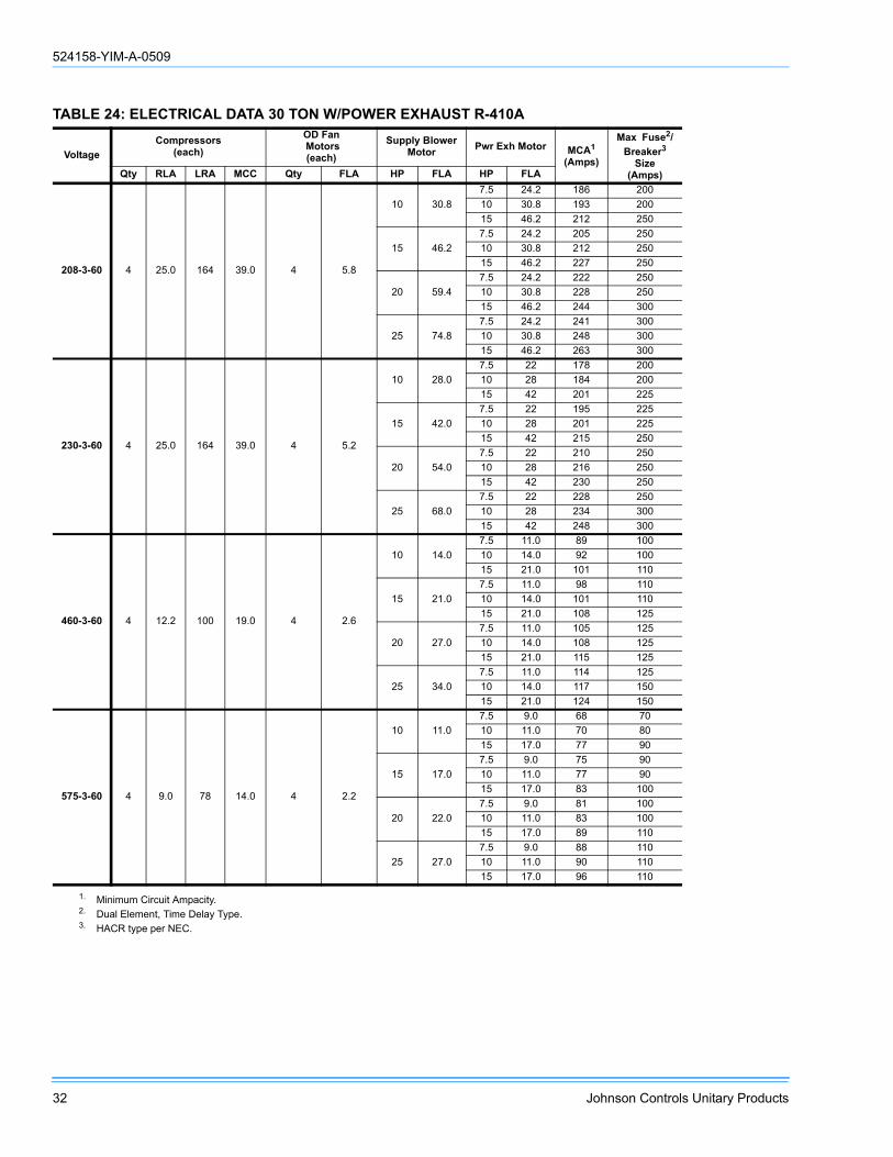
524158-YIM-A-0509
32 Johnson Controls Unitary Products
TABLE 24: ELECTRICAL DATA 30 TON W/POWER EXHAUST R-410A
VoltageCompressors
(each)OD Fan Motors(each)
Supply BlowerMotor Pwr Exh Motor MCA1
(Amps)
Max Fuse2/Breaker3
Size(Amps)Qty RLA LRA MCC Qty FLA HP FLA HP FLA
208-3-60 4 25.0 164 39.0 4 5.8
10 30.87.5 24.2 186 20010 30.8 193 20015 46.2 212 250
15 46.27.5 24.2 205 25010 30.8 212 25015 46.2 227 250
20 59.47.5 24.2 222 25010 30.8 228 25015 46.2 244 300
25 74.87.5 24.2 241 30010 30.8 248 30015 46.2 263 300
230-3-60 4 25.0 164 39.0 4 5.2
10 28.07.5 22 178 20010 28 184 20015 42 201 225
15 42.07.5 22 195 22510 28 201 22515 42 215 250
20 54.07.5 22 210 25010 28 216 25015 42 230 250
25 68.07.5 22 228 25010 28 234 30015 42 248 300
460-3-60 4 12.2 100 19.0 4 2.6
10 14.07.5 11.0 89 10010 14.0 92 10015 21.0 101 110
15 21.07.5 11.0 98 11010 14.0 101 11015 21.0 108 125
20 27.07.5 11.0 105 12510 14.0 108 12515 21.0 115 125
25 34.07.5 11.0 114 12510 14.0 117 15015 21.0 124 150
575-3-60 4 9.0 78 14.0 4 2.2
10 11.07.5 9.0 68 7010 11.0 70 8015 17.0 77 90
15 17.07.5 9.0 75 9010 11.0 77 9015 17.0 83 100
20 22.07.5 9.0 81 10010 11.0 83 10015 17.0 89 110
25 27.07.5 9.0 88 11010 11.0 90 11015 17.0 96 110
1. Minimum Circuit Ampacity.2. Dual Element, Time Delay Type.3. HACR type per NEC.
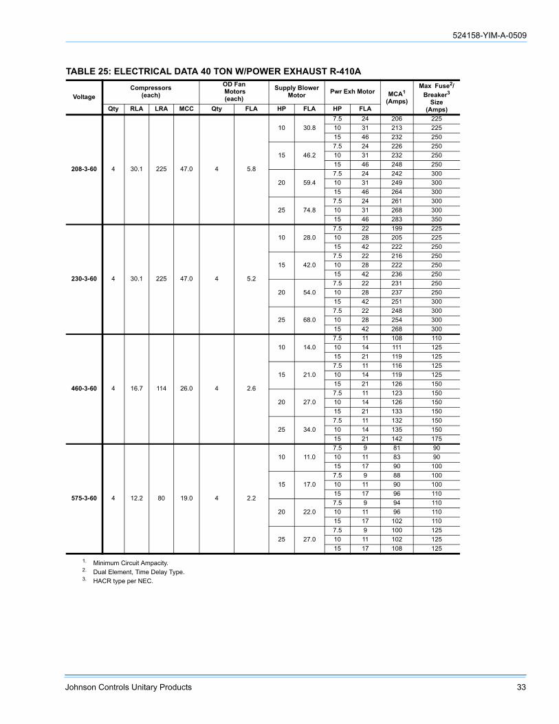
524158-YIM-A-0509
Johnson Controls Unitary Products 33
TABLE 25: ELECTRICAL DATA 40 TON W/POWER EXHAUST R-410A
VoltageCompressors
(each)OD Fan Motors(each)
Supply BlowerMotor Pwr Exh Motor MCA1
(Amps)
Max Fuse2/Breaker3
Size(Amps)Qty RLA LRA MCC Qty FLA HP FLA HP FLA
208-3-60 4 30.1 225 47.0 4 5.8
10 30.87.5 24 206 22510 31 213 22515 46 232 250
15 46.27.5 24 226 25010 31 232 25015 46 248 250
20 59.47.5 24 242 30010 31 249 30015 46 264 300
25 74.87.5 24 261 30010 31 268 30015 46 283 350
230-3-60 4 30.1 225 47.0 4 5.2
10 28.07.5 22 199 22510 28 205 22515 42 222 250
15 42.07.5 22 216 25010 28 222 25015 42 236 250
20 54.07.5 22 231 25010 28 237 25015 42 251 300
25 68.07.5 22 248 30010 28 254 30015 42 268 300
460-3-60 4 16.7 114 26.0 4 2.6
10 14.07.5 11 108 11010 14 111 12515 21 119 125
15 21.07.5 11 116 12510 14 119 12515 21 126 150
20 27.07.5 11 123 15010 14 126 15015 21 133 150
25 34.07.5 11 132 15010 14 135 15015 21 142 175
575-3-60 4 12.2 80 19.0 4 2.2
10 11.07.5 9 81 9010 11 83 9015 17 90 100
15 17.07.5 9 88 10010 11 90 10015 17 96 110
20 22.07.5 9 94 11010 11 96 11015 17 102 110
25 27.07.5 9 100 12510 11 102 12515 17 108 125
1. Minimum Circuit Ampacity.2. Dual Element, Time Delay Type.3. HACR type per NEC.

524158-YIM-A-0509
34 Johnson Controls Unitary Products
TABLE 26: ELECTRICAL DATA 25 TON W/ELECTRIC HEAT AND POWER EXHAUST R-410A
VoltageElectric Heat Option Compressors
(each)OD Fan Motors
(each)Supply Blower
Motor Pwr Exh MotorMCA1
(Amps)
Max Fuse2/Breaker3
Size(Amps)
Model KW Stages Amps Qty RLA LRA MCC Qty FLA HP FLA HP FLA
208-3-60
E4 40 1 83.4 4 23.0 160 36.0 4 4.5
7.5 24.25 16.7 157 175
7.5 24.2 165 17510 30.8 173 200
10 30.85 16.7 165 175
7.5 24.2 173 20010 30.8 180 200
15 46.25 16.7 185 225
7.5 24.2 192 22510 30.8 199 225
20 59.45 16.7 201 250
7.5 24.2 209 25010 30.8 215 250
E8 80 2 166.8 4 23.0 160 36.0 4 4.5
7.5 24.25 16.7 214 225
7.5 24.2 221 22510 30.8 229 250
10 30.85 16.7 222 250
7.5 24.2 229 25010 30.8 236 250
15 46.25 16.7 241 250
7.5 24.2 249 25010 30.8 255 300
20 59.45 16.7 258 300
7.5 24.2 265 30010 30.8 272 300
230-3-60
E4 40 1 92.2 4 23.0 160 36.0 4 4.3
7.5 22.05 15.2 163 175
7.5 22.0 170 17510 28.0 177 200
10 28.05 15.2 170 175
7.5 22.0 177 20010 28.0 183 200
15 42.05 15.2 188 200
7.5 22.0 195 22510 28.0 201 225
20 54.05 15.2 203 225
7.5 22.0 210 25010 28.0 216 250
E8 80 2 184.4 4 23.0 160 36.0 4 4.3
7.5 22.05 15.2 235 250
7.5 22.0 242 25010 28.0 249 250
10 28.05 15.2 243 250
7.5 22.0 249 25010 28.0 255 300
15 42.05 15.2 260 300
7.5 22.0 267 30010 28.0 273 300
20 54.05 15.2 275 300
7.5 22.0 282 30010 28.0 288 300

524158-YIM-A-0509
Johnson Controls Unitary Products 35
460-3-60
E4 40 1 46.1 4 12.2 87 19.0 4 2.2
7.5 11.05 7.6 84 90
7.5 11.0 87 9010 14.0 91 100
10 14.05 7.6 88 100
7.5 11.0 91 10010 14.0 94 100
15 21.05 7.6 96 110
7.5 11.0 100 11010 14.0 103 110
20 27.05 7.6 104 125
7.5 11.0 107 12510 14.0 110 125
E8 80 2 92.2 4 12.2 87 19.0 4 2.2
7.5 11.05 7.6 118 125
7.5 11.0 121 12510 14.0 125 125
10 14.05 7.6 121 125
7.5 11.0 125 12510 14.0 128 150
15 21.05 7.6 130 150
7.5 11.0 133 15010 14.0 136 150
20 27.05 7.6 138 150
7.5 11.0 141 15010 14.0 144 150
E1 108 3 124.5 4 12.2 87 19.0 4 2.2
7.5 11.05 7.6 151 175
7.5 11.0 155 17510 14.0 158 175
10 14.05 7.6 155 175
7.5 11.0 158 17510 14.0 161 175
15 21.05 7.6 164 175
7.5 11.0 167 17510 14.0 170 175
20 27.05 7.6 171 175
7.5 11.0 175 20010 14.0 178 200
TABLE 26: ELECTRICAL DATA 25 TON W/ELECTRIC HEAT AND POWER EXHAUST R-410A (CONTINUED)
VoltageElectric Heat Option Compressors
(each)OD Fan Motors
(each)Supply Blower
Motor Pwr Exh MotorMCA1
(Amps)
Max Fuse2/Breaker3
Size(Amps)
Model KW Stages Amps Qty RLA LRA MCC Qty FLA HP FLA HP FLA

524158-YIM-A-0509
36 Johnson Controls Unitary Products
575-3-60
E4 40 1 40.2 4 8.6 62 13.5 4 1.7
7.5 9.05 6.1 69 70
7.5 9.0 68 7010 11.0 75 80
10 11.05 6.1 68 70
7.5 9.0 71 8010 11.0 73 80
15 17.05 6.1 75 80
7.5 9.0 78 8010 11.0 80 90
20 22.05 6.1 82 90
7.5 9.0 85 9010 11.0 87 100
E8 80 2 80.3 4 8.6 62 13.5 4 1.7
7.5 9.05 6.1 94 100
7.5 9.0 97 10010 11.0 100 110
10 11.05 6.1 97 100
7.5 9.0 100 11010 11.0 102 110
15 17.05 6.1 104 110
7.5 9.0 107 11010 11.0 109 125
20 22.05 6.1 111 125
7.5 9.0 113 12510 11.0 122 125
E1 108 3 108.4 4 8.6 62 13.5 4 1.7
7.5 9.05 6.1 121 150
7.5 9.0 124 15010 11.0 127 150
10 11.05 6.1 124 150
7.5 9.0 127 15010 11.0 129 150
15 17.05 6.1 131 150
7.5 9.0 134 15010 11.0 136 150
20 22.05 6.1 138 150
7.5 9.0 140 15010 11.0 149 150
1. Minimum Circuit Ampacity.2. Dual Element, Time Delay Type.3. HACR type per NEC.
TABLE 26: ELECTRICAL DATA 25 TON W/ELECTRIC HEAT AND POWER EXHAUST R-410A (CONTINUED)
VoltageElectric Heat Option Compressors
(each)OD Fan Motors
(each)Supply Blower
Motor Pwr Exh MotorMCA1
(Amps)
Max Fuse2/Breaker3
Size(Amps)
Model KW Stages Amps Qty RLA LRA MCC Qty FLA HP FLA HP FLA

524158-YIM-A-0509
Johnson Controls Unitary Products 37
TABLE 27: ELECTRICAL DATA 30 TON W/ELECTRIC HEAT AND POWER EXHAUST R-410A
VoltageElectric Heat Option Compressors
(each)OD Fan Motors
(each)Supply Blower
Motor Pwr Exh MotorMCA1
(Amps)
Max Fuse2/Breaker3
Size(Amps)
Model KW Stages Amps Qty RLA LRA MCC Qty FLA HP FLA HP FLA
208-3-60
E4 40 1 83.4 4 25.0 164 39.0 4 5.8
10 30.87.5 24.2 186 20010 30.8 193 20015 46.2 212 250
15 46.27.5 24.2 205 25010 30.8 212 25015 46.2 227 250
20 59.47.5 24.2 222 25010 30.8 228 25015 46.2 244 300
25 74.87.5 24.2 241 30010 30.8 248 30015 46.2 263 300
E8 80 2 166.8 4 25.0 164 39.0 4 5.8
10 30.87.5 24.2 229 25010 30.8 236 25015 46.2 255 300
15 46.27.5 24.2 249 25010 30.8 255 30015 46.2 271 300
20 59.47.5 24.2 265 30010 30.8 272 30015 46.2 287 300
25 74.87.5 24.2 284 35010 30.8 291 35015 46.2 308 350
230-3-60
E4 40 1 92.2 4 25.0 164 39.0 4 5.2
10 28.07.5 22.0 178 20010 28.0 184 20015 42.0 201 225
15 42.07.5 22.0 195 22510 28.0 201 22515 42.0 215 250
20 54.07.5 22.0 210 25010 28.0 216 25015 42.0 230 250
25 68.07.5 22.0 228 25010 28.0 234 30015 42.0 248 300
E8 80 2 184.4 4 25.0 164 39.0 4 5.2
10 28.07.5 22.0 249 25010 28.0 255 30015 42.0 273 300
15 42.07.5 22.0 267 30010 28.0 273 30015 42.0 287 300
20 54.07.5 22.0 282 30010 28.0 288 30015 42.0 302 350
25 68.07.5 22.0 299 35010 28.0 305 35015 42.0 319 350
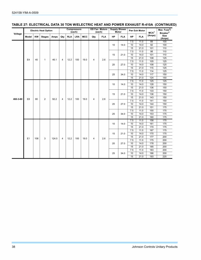
524158-YIM-A-0509
38 Johnson Controls Unitary Products
460-3-60
E4 40 1 46.1 4 12.2 100 19.0 4 2.6
10 14.07.5 11.0 89 10010 14.0 92 10015 21.0 101 110
15 21.07.5 11.0 98 11010 14.0 101 11015 21.0 108 125
20 27.07.5 11.0 105 12510 14.0 108 12515 21.0 115 125
25 34.07.5 11.0 114 12510 14.0 117 15015 21.0 124 150
E8 80 2 92.2 4 12.2 100 19.0 4 2.6
10 14.07.5 11.0 125 12510 14.0 128 15015 21.0 136 150
15 21.07.5 11.0 133 15010 14.0 136 15015 21.0 143 150
20 27.07.5 11.0 141 15010 14.0 144 15015 21.0 151 175
25 34.07.5 11.0 150 17510 14.0 153 17515 21.0 160 175
E1 108 3 124.5 4 12.2 100 19.0 4 2.6
10 14.07.5 11.0 158 17510 14.0 161 17515 21.0 170 175
15 21.07.5 11.0 167 17510 14.0 170 17515 21.0 177 200
20 27.07.5 11.0 175 20010 14.0 178 20015 21.0 185 200
25 34.07.5 11.0 183 20010 14.0 186 20015 21.0 193 225
TABLE 27: ELECTRICAL DATA 30 TON W/ELECTRIC HEAT AND POWER EXHAUST R-410A (CONTINUED)
VoltageElectric Heat Option Compressors
(each)OD Fan Motors
(each)Supply Blower
Motor Pwr Exh MotorMCA1
(Amps)
Max Fuse2/Breaker3
Size(Amps)
Model KW Stages Amps Qty RLA LRA MCC Qty FLA HP FLA HP FLA

524158-YIM-A-0509
Johnson Controls Unitary Products 39
575-3-60
E4 40 1 40.2 4 9.0 78 14.0 4 2.2
10 11.07.5 9.0 71 8010 11.0 73 8015 17.0 80 90
15 17.07.5 9.0 78 9010 11.0 80 9015 17.0 86 100
20 22.07.5 9.0 85 10010 11.0 87 10015 17.0 93 110
25 27.07.5 9.0 91 11010 11.0 93 11015 17.0 99 110
E8 80 2 80.3 4 9.0 78 14.0 4 2.2
10 11.07.5 9.0 100 11010 11.0 102 11015 17.0 109 125
15 17.07.5 9.0 107 11010 11.0 109 12515 17.0 115 125
20 22.07.5 9.0 113 12510 11.0 115 12515 17.0 121 125
25 27.07.5 9.0 120 12510 11.0 122 12515 17.0 128 150
E1 108 3 108.4 4 9.0 78 14.0 4 2.2
10 11.07.5 9.0 127 15010 11.0 129 15015 17.0 136 150
15 17.07.5 9.0 134 15010 11.0 136 15015 17.0 142 150
20 22.07.5 9.0 140 15010 11.0 142 15015 17.0 148 150
25 27.07.5 9.0 147 15010 11.0 149 17515 17.0 155 175
1. Minimum Circuit Ampacity.2. Dual Element, Time Delay Type.3. HACR type per NEC.
TABLE 27: ELECTRICAL DATA 30 TON W/ELECTRIC HEAT AND POWER EXHAUST R-410A (CONTINUED)
VoltageElectric Heat Option Compressors
(each)OD Fan Motors
(each)Supply Blower
Motor Pwr Exh MotorMCA1
(Amps)
Max Fuse2/Breaker3
Size(Amps)
Model KW Stages Amps Qty RLA LRA MCC Qty FLA HP FLA HP FLA

524158-YIM-A-0509
40 Johnson Controls Unitary Products
TABLE 28: ELECTRICAL DATA 40 TON W/ELECTRIC HEAT AND POWER EXHAUST R-410A
VoltageElectric Heat Option Compressors
(each)OD Fan Motors
(each)Supply Blower
Motor Pwr Exh MotorMCA1
(Amps)
Max Fuse2/Breaker3
Size(Amps)
Model KW Stages Amps Qty RLA LRA MCC Qty FLA HP FLA HP FLA
208-3-60
E4 40 1 83.4 4 30.1 225 47.0 4 5.8
10 30.87.5 24 206 22510 31 213 22515 46 232 250
15 46.27.5 24 226 25010 31 232 25015 46 248 250
20 59.47.5 24 242 30010 31 249 30015 46 264 300
25 74.87.5 24 261 30010 31 268 30015 46 283 350
E8 80 2 166.8 4 30.1 225 47.0 4 5.8
10 30.87.5 24 229 25010 31 236 25015 46 255 300
15 46.27.5 24 249 25010 31 255 30015 46 271 300
20 59.47.5 24 265 30010 31 272 30015 46 287 300
25 74.87.5 24 284 35010 31 291 35015 46 306 350
230-3-60
E4 40 1 92.2 4 30.1 225 47.0 4 5.2
10 28.07.5 22 199 22510 28 205 22515 42 222 250
15 42.07.5 22 216 25010 28 222 25015 42 236 250
20 54.07.5 22 231 25010 28 237 25015 42 251 300
25 68.07.5 22 248 30010 28 254 30015 42 268 300
E8 80 2 184.4 4 30.1 225 47.0 4 5.2
10 28.07.5 22 249 25010 28 255 30015 42 273 300
15 42.07.5 22 267 30010 28 273 30015 42 287 300
20 54.07.5 22 282 30010 28 288 30015 42 302 350
25 68.07.5 22 299 35010 28 305 35015 42 319 350

524158-YIM-A-0509
Johnson Controls Unitary Products 41
460-3-60
E4 40 1 46.1 4 16.7 114 26.0 4 2.6
10 14.07.5 11 108 11010 14 111 12515 21 119 125
15 21.07.5 11 116 12510 14 119 12515 21 126 150
20 27.07.5 11 123 12510 14 126 15015 21 133 150
25 34.07.5 11 132 15010 14 135 15015 21 142 175
E8 80 2 92.2 4 16.7 114 26.0 4 2.6
10 14.07.5 11 125 12510 14 128 15015 21 136 150
15 21.07.5 11 133 15010 14 136 15015 21 143 150
20 27.07.5 11 141 15010 14 144 15015 21 151 175
25 34.07.5 11 150 17510 14 153 17515 21 160 175
E1 108 3 124.5 4 16.7 114 26.0 4 2.6
10 14.07.5 11 158 17510 14 161 17515 21 170 175
15 21.07.5 11 167 17510 14 170 17515 21 177 200
20 27.07.5 11 175 20010 14 178 20015 21 185 200
25 34.07.5 11 183 20010 14 186 20015 21 193 200
TABLE 28: ELECTRICAL DATA 40 TON W/ELECTRIC HEAT AND POWER EXHAUST R-410A (CONTINUED)
VoltageElectric Heat Option Compressors
(each)OD Fan Motors
(each)Supply Blower
Motor Pwr Exh MotorMCA1
(Amps)
Max Fuse2/Breaker3
Size(Amps)
Model KW Stages Amps Qty RLA LRA MCC Qty FLA HP FLA HP FLA

524158-YIM-A-0509
42 Johnson Controls Unitary Products
575-3-60
E4 40 1 40.2 4 12.2 80 19.0 4 2.2
10 11.07.5 9 81 9010 11 83 9015 17 90 100
15 17.07.5 9 88 10010 11 90 10015 17 96 110
20 22.07.5 9 94 11010 11 96 11015 17 102 110
25 27.07.5 9 100 12510 11 102 12515 17 108 125
E8 80 2 80.3 4 12.2 80 19.0 4 2.2
10 11.07.5 9 100 11010 11 102 11015 17 109 125
15 17.07.5 9 107 11010 11 109 12515 17 115 125
20 22.07.5 9 113 12510 11 115 12515 17 121 125
25 27.07.5 9 120 15010 11 122 15015 17 128 150
E1 108 3 108.4 4 12.2 80 19.0 4 2.2
10 11.07.5 9 127 15010 11 129 15015 17 136 150
15 17.07.5 9 134 15010 11 136 15015 17 142 150
20 22.07.5 9 140 15010 11 142 15015 17 148 150
25 27.07.5 9 147 15010 11 156 17515 17 155 175
1. Minimum Circuit Ampacity.2. Dual Element, Time Delay Type.3. HACR type per NEC.
TABLE 28: ELECTRICAL DATA 40 TON W/ELECTRIC HEAT AND POWER EXHAUST R-410A (CONTINUED)
VoltageElectric Heat Option Compressors
(each)OD Fan Motors
(each)Supply Blower
Motor Pwr Exh MotorMCA1
(Amps)
Max Fuse2/Breaker3
Size(Amps)
Model KW Stages Amps Qty RLA LRA MCC Qty FLA HP FLA HP FLA
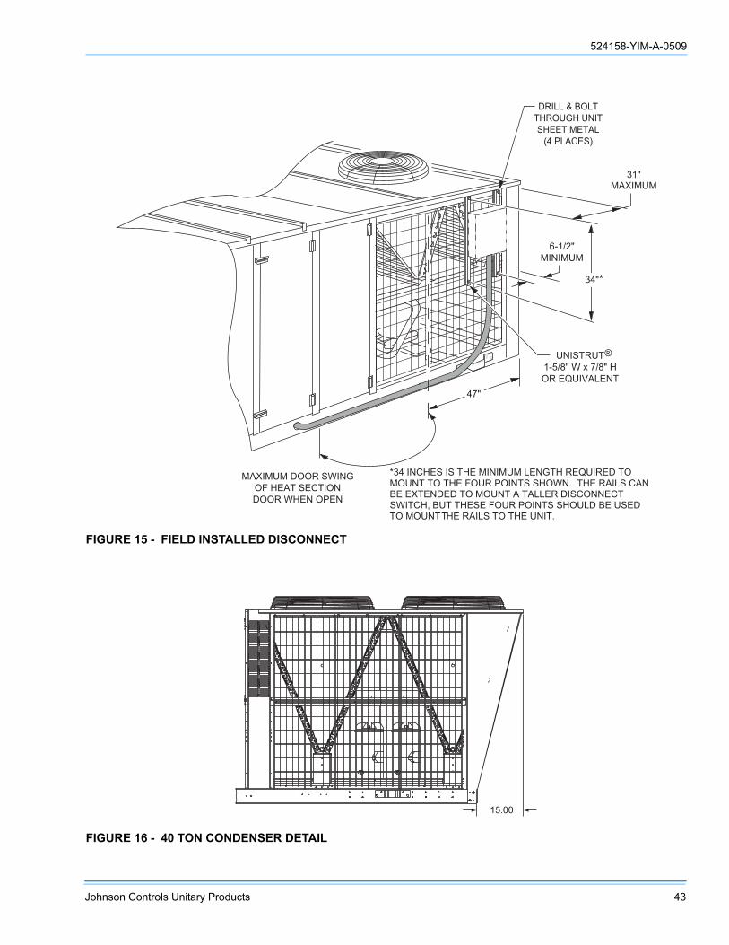
524158-YIM-A-0509
Johnson Controls Unitary Products 43
FIGURE 15 - FIELD INSTALLED DISCONNECT
31"MAXIMUM
DRILL & BOLTTHROUGH UNITSHEET METAL
(4 PLACES)
34"*
6-1/2"MINIMUM
MAXIMUM DOOR SWINGOF HEAT SECTIONDOOR WHEN OPEN
UNISTRUT1-5/8" W x 7/8" HOR EQUIVALENT
47"
*34 INCHES IS THE MINIMUM LENGTH REQUIRED TO MOUNT TO THE FOUR POINTS SHOWN. THE RAILS CANBE EXTENDED TO MOUNT A TALLER DISCONNECT SWITCH, BUT THESE FOUR POINTS SHOULD BE USED TO MOUNTTHE RAILS TO THE UNIT.
®
FIGURE 16 - 40 TON CONDENSER DETAIL
15.00

524158-YIM-A-0509
44 Johnson Controls Unitary Products
FIGURE 17 - PARTIAL ROOF CURB MODEL 1RC0455P
� � � � �
� � � � �
� � � � � � � � ! � � �
� � � � � �
" � � �
� � � �
� " � � �
� � � ! �
� � � �
� � �� � �
� � � � � #
� � � � �� � �
� � � � � #
� � � � � � � � $ � � � % � � � � &
� � � � � # � � % �
� � � ' � " �� � � � �
� " � # � � � # � ( � � � � � � � � � � � � �
� � � � � � � � � � � �
$ � " � � � &
�
�
� � � � � � � ' �
� � � � � � � � � � � � � � � � � � � � �
� � � � �
� � � � �
� � � � �
� � � � �
� � � � �
� � �
( ) * + , - . / ( � 0 1 2� 3 / - 2 4 - / 3
� 5 2 2 - � � 2 - , +� / ) 2 � � . 2 4 2 !
� � � � � � � � �� � � �
�
�
� � ' � � � � � � � � � � � � � � � � � �� � ' � � � � � � � � � � � � � � � � � � � � �
� � � 6 � � 3 / - 2 4 - � . ( ) * + , - . / ( � 7 . - 5 � , � ) 5 2 2 - � 8 2 - , +( / ) 2 � 9 . 2 4 2 � 7 5 2 ( � . ( ) - , + + . ( 1 � , � . ( - 2 3 ( , + + : � . ( ) * + , - 2 00 * 4 - � 7 / 3 ; �
� : 9 . 4 , + � ( ) * + , - . / (
� � � � � � � � � � � � � � � � � � � � �

524158-YIM-A-0509
Johnson Controls Unitary Products 45
CFM, STATIC PRESSURE, AND POWER - ALTI-TUDE AND TEMPERATURE CORRECTIONS
The information below should be used to assist in applicationof product when being applied at altitudes at or exceeding1000 feet above sea level.
The air flow rates listed in the standard blower performancetables are based on standard air at sea level. As the altitudeor temperature increases, the density of air decreases. In
order to use the indoor blower tables for high altitude applica-tions, certain corrections are necessary.
A centrifugal fan is a "constant volume" device. This meansthat, if the rpm remains constant, the CFM delivered is thesame regardless of the density of the air. However, since theair at high altitude is less dense, less static pressure will begenerated and less power will be required than a similarapplication at sea level. Air density correction factors areshown in Table 29 and Figure 18.
The examples below will assist in determining the airflow per-formance of the product at altitude.
Example 1: What are the corrected CFM, static pressure,and BHP at an elevation of 5,000 ft. if the blower performancedata is 6,000 CFM, 1.5 IWC and 4.0 BHP?
Solution: At an elevation of 5,000 ft the indoor blower will stilldeliver 6,000 CFM if the rpm is unchanged. However, Table29 must be used to determine the static pressure and BHP.Since no temperature data is given, we will assume an airtemperature of 70°F. Table 29 shows the correction factor tobe 0.832.
Corrected static pressure = 1.5 x 0.832 = 1.248 IWC
Corrected BHP = 4.0 x 0.832 = 3.328
Example 2: A system, located at 5,000 feet of elevation, is todeliver 6,000 CFM at a static pressure of 1.5". Use the unit
blower tables to select the blower speed and the BHPrequirement.
Solution: As in the example above, no temperature informa-tion is given so 70°F is assumed.
The 1.5" static pressure given is at an elevation of 5,000 ft.The first step is to convert this static pressure to equivalentsea level conditions.
Sea level static pressure = 1.5 / .832 = 1.80"
Enter the blower table at 6000 sCFM and static pressure of1.8". The rpm listed will be the same rpm needed at 5,000 ft.
Suppose that the corresponding BHP listed in the table is 3.2.This value must be corrected for elevation.
BHP at 5,000 ft = 3.2 x .832 = 2.66
TABLE 29: ALTITUDE CORRECTION FACTORS
AIR TEMP ALTITUDE (FEET)
0 1000 2000 3000 4000 5000 6000 7000 8000 9000 10000
40 1.060 1.022 0.986 0.950 0.916 0.882 0.849 0.818 0.788 0.758 0.729
50 1.039 1.002 0.966 0.931 0.898 0.864 0.832 0.802 0.772 0.743 0.715
60 1.019 0.982 0.948 0.913 0.880 0.848 0.816 0.787 0.757 0.729 0.701
70 1.000 0.964 0.930 0.896 0.864 0.832 0.801 0.772 0.743 0.715 0.688
80 0.982 0.947 0.913 0.880 0.848 0.817 0.787 0.758 0.730 0.702 0.676
90 0.964 0.929 0.897 0.864 0.833 0.802 0.772 0.744 0.716 0.689 0.663
100 0.946 0.912 0.880 0.848 0.817 0.787 0.758 0.730 0.703 0.676 0.651
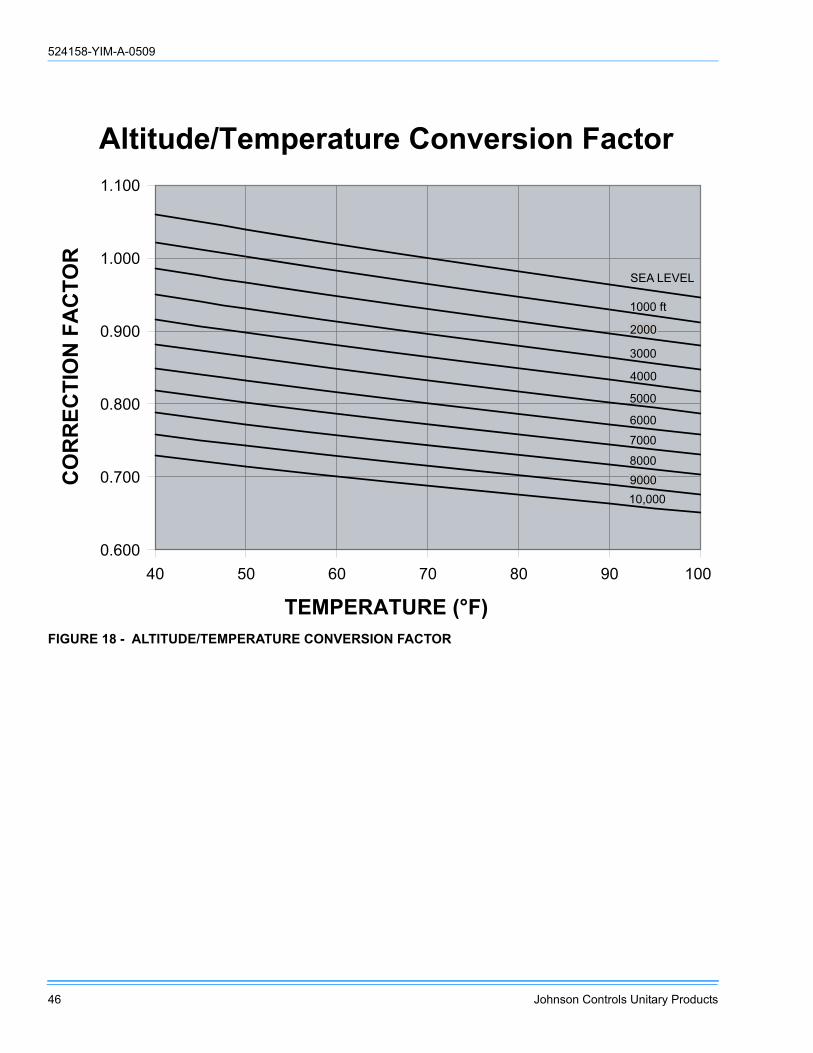
524158-YIM-A-0509
46 Johnson Controls Unitary Products
FIGURE 18 - ALTITUDE/TEMPERATURE CONVERSION FACTOR
������������� ���� ���������� � ����
�����
�����
�����
�����
�����
�����
�� � �� �� �� �� ���
��������� ����
�������� �����
�� �����
���� ��
����
����
���
����
����
����
����
������
����

524158-YIM-A-0509
Johnson Controls Unitary Products 47
4. Shaded RPMs require Class II blower.
TABLE 30: FAN PERFORMANCE - 25 TON1, 2
AIRFLOW CFMAVAILABLE EXTERNAL STATIC PRESSURE (IWG)
0.2 0.4 0.6 0.8 1.0RPM BHP3 RPM BHP3 RPM BHP3 RPM BHP3 RPM BHP3
4000 302 0.5 365 0.7 422 1.0 475 1.3 523 1.55000 341 0.9 396 1.1 447 1.4 495 1.7 540 2.06000 380 1.2 427 1.5 473 1.8 516 2.1 557 2.57000 416 1.8 459 2.1 500 2.5 540 2.8 578 3.28000 452 2.3 491 2.7 528 3.1 565 3.5 600 3.99000 492 3.2 527 3.6 561 4.0 594 4.5 626 4.910000 532 4.2 563 4.5 594 4.9 624 5.4 653 5.811000 578 5.5 605 5.9 632 6.3 659 6.7 686 7.212000 623 6.8 647 7.2 671 7.6 695 8.1 719 8.612500 639 7.4 664 7.9 688 8.4 712 8.9 736 9.5
AIRFLOW CFMAVAILABLE EXTERNAL STATIC PRESSURE (IWG)
1.2 1.4 1.6 1.8 2.0RPM BHP3 RPM BHP3 RPM BHP3 RPM BHP3 RPM BHP3
4000 568 1.8 609 2.2 646 2.5 681 2.8 713 3.25000 582 2.4 621 2.7 657 3.1 692 3.5 724 3.96000 596 2.9 633 3.3 669 3.7 702 4.1 735 4.57000 615 3.6 650 4.0 683 4.5 716 4.9 747 5.48000 633 4.4 666 4.8 698 5.3 729 5.7 759 6.29000 658 5.3 688 5.8 718 6.3 747 6.8 776 7.310000 682 6.3 710 6.8 738 7.3 766 7.8 793 8.411000 713 7.7 739 8.2 765 8.8 791 9.3 816 9.912000 743 9.1 767 9.7 791 10.2 815 10.8 839 11.412500 760 10.0 784 10.6 807 11.2 830 11.7 853 12.3
AIRFLOW CFMAVAILABLE EXTERNAL STATIC PRESSURE (IWG)
2.2 2.4 2.6 2.8 3.0RPM BHP3 RPM BHP3 RPM BHP3 RPM BHP3 RPM BHP3
4000 743 3.5 770 3.9 796 4.3 821 4.6 844 5.05000 754 4.3 783 4.7 810 5.1 836 5.5 861 5.96000 766 5.0 795 5.4 824 5.9 851 6.4 878 6.87000 777 5.8 806 6.3 834 6.8 861 7.3 888 7.88000 788 6.7 817 7.2 844 7.7 871 8.2 898 8.89000 804 7.8 831 8.3 857 8.9 883 9.5 909 10.010000 819 8.9 845 9.5 870 10.1 896 10.7 920 11.311000 841 10.5 866 11.1 890 11.7 914 12.3 938 12.912000 863 12.0 887 12.6 910 13.2 933 13.9 956 14.512500 876 12.9 899 13.6 921 14.2 943 14.8 965 15.5
AIRFLOW CFMAVAILABLE EXTERNAL STATIC PRESSURE (IWG)
3.2 3.4 3.6 3.8 4.0RPM BHP3 RPM BHP3 RPM BHP3 RPM BHP3 RPM BHP3
4000 867 5.4 890 5.8 912 6.2 935 6.6 958 6.95000 885 6.4 909 6.8 932 7.2 956 7.6 979 8.06000 903 7.3 928 7.8 953 8.2 976 8.7 1000 9.17000 914 8.3 939 8.8 963 9.4 988 9.9 1012 10.58000 924 9.3 949 9.9 974 10.5 999 11.2 1023 11.89000 934 10.6 959 11.2 983 11.9 1007 12.5 1030 13.210000 944 11.9 968 12.6 992 13.2 1015 13.8 1037 14.511000 961 13.6 984 14.2 1007 14.9 1029 15.6 1051 16.212000 978 15.2 1000 15.9 1022 16.6 1043 17.3 1064 18.013000 986 16.2 1008 16.8 1029 17.5 1050 18.2 1070 19.0
1. Fan performance is based on wet evaporator coils, clean 2” throwaway filters and system/cabinet effects at standard air density and 0 feet elevation.2. Refer to Tables 57, 15, 21 and 33 for component additions and deductions to fan performance tables.3. BHP includes drive losses.

524158-YIM-A-0509
48 Johnson Controls Unitary Products
FIGURE 19 - FAN PERFORMANCE - 25 TON
0 1 2 3 4 5 6 7 8 9 10 11 12 13
CFM (x1000)
0.0
0.5
1.0
1.5
2.0
2.5
3.0
3.5
4.0
4.5
5.0
5.5
6.0
6.5
7.0
7.5
8.0
Tot
al S
tatic
Pre
ssur
e (I
WG
)
1100 RPM
900
800
700
600
500
1000
A
25 Ton Forward Curve
10
15 BHP
20
7.5
A - Standard Unit
Note: Standard Unit includes wet evaporator coil, clean 2" throwaway filters, systemand cabinet effects at standard air density and 0' elevation.

524158-YIM-A-0509
Johnson Controls Unitary Products 49
4. Shaded RPMs require Class II blower.
TABLE 31: FAN PERFORMANCE - 30 TON 1, 2
AIRFLOW (CFM)AVAILABLE EXTERNAL STATIC PRESSURE (IWG)
0.2 0.4 0.6 0.8 1.0RPM BHP3 RPM BHP3 RPM BHP3 RPM BHP3 RPM BHP3
6000 405 1.3 450 1.6 494 2.0 535 2.3 575 2.77000 444 1.9 485 2.3 524 2.7 562 3.0 599 3.48000 483 2.6 519 2.9 555 3.3 589 3.7 623 4.29000 520 3.5 554 3.9 586 4.3 618 4.7 649 5.210000 558 4.5 588 4.8 618 5.2 647 5.7 676 6.211000 603 5.7 629 6.2 656 6.7 683 7.2 709 7.712000 647 7.0 671 7.5 695 8.1 718 8.6 742 9.213000 687 8.9 709 9.3 731 9.9 753 10.4 776 10.914000 728 10.7 748 11.2 768 11.6 789 12.2 809 12.715000 767 12.7 786 13.2 805 13.8 825 14.4 845 15.0
AIRFLOW (CFM)AVAILABLE EXTERNAL STATIC PRESSURE (IWG)
1.2 1.4 1.6 1.8 2.0RPM BHP3 RPM BHP3 RPM BHP3 RPM BHP3 RPM BHP3
6000 612 3.1 649 3.5 683 3.9 717 4.3 748 4.77000 634 3.8 668 4.3 701 4.7 733 5.1 763 5.68000 655 4.6 687 5.1 719 5.5 749 6.0 779 6.59000 680 5.6 710 6.1 739 6.6 768 7.2 796 7.710000 704 6.7 732 7.2 760 7.7 787 8.3 813 8.911000 735 8.2 761 8.7 787 9.3 812 9.8 837 10.412000 766 9.7 790 10.3 814 10.8 837 11.4 861 12.013000 798 11.5 820 12.1 843 12.7 865 13.3 887 13.914000 830 13.3 851 13.9 872 14.6 893 15.2 914 15.915000 864 15.6 884 16.3 904 16.9 923 17.6 943 18.3
AIRFLOW (CFM)AVAILABLE EXTERNAL STATIC PRESSURE (IWG)
2.2 2.4 2.6 2.8 3.0RPM BHP3 RPM BHP3 RPM BHP3 RPM BHP3 RPM BHP3
6000 779 5.1 808 5.5 837 6.0 864 6.4 890 6.97000 793 6.1 822 6.6 850 7.0 877 7.5 903 8.18000 807 7.0 836 7.6 863 8.1 890 8.6 916 9.29000 823 8.3 850 8.8 877 9.4 902 10.0 928 10.610000 839 9.5 865 10.1 890 10.7 915 11.3 940 12.011000 862 11.0 886 11.6 910 12.2 934 12.9 957 13.512000 884 12.5 907 13.2 930 13.8 953 14.4 975 15.013000 909 14.6 931 15.2 953 15.9 975 16.5 996 17.214000 935 16.6 956 17.3 976 18.0 997 18.7 1017 19.415000 963 18.9 982 19.6 1002 20.4 1021 21.1 1040 21.8
AIRFLOW (CFM)AVAILABLE EXTERNAL STATIC PRESSURE (IWG)
3.2 3.4 3.6 3.8 4.0RPM BHP3 RPM BHP3 RPM BHP3 RPM BHP3 RPM BHP3
6000 916 7.4 940 7.9 964 8.3 988 8.8 1011 9.37000 928 8.6 953 9.1 977 9.6 1000 10.1 1023 10.78000 941 9.8 965 10.3 989 10.9 1013 11.5 1035 12.09000 952 11.2 976 11.8 1000 12.4 1023 13.0 1045 13.610000 964 12.6 987 13.2 1010 13.9 1033 14.5 1055 15.111000 981 14.1 1003 14.8 1025 15.5 1047 16.1 1069 16.812000 997 15.7 1019 16.4 1040 17.1 1061 17.8 1082 18.513000 1017 17.9 1038 18.6 1058 19.4 1078 20.1 1097 20.814000 1037 20.2 1056 20.9 1076 21.6 1094 22.4 1113 23.115000 1059 22.6 1078 23.3 1097 24.1 1115 24.9 1134 25.7
1. Fan performance is based on wet evaporator coils, clean 2” throwaway filters and system/cabinet effects at standard air density and 0 feet elevation.2. Refer to Tables 57, 15, 21 and 33 for component additions and deductions to fan performance tables.3. BHP includes drive losses.

524158-YIM-A-0509
50 Johnson Controls Unitary Products
FIGURE 20 - FAN PERFORMANCE - 30 TON
0 1 2 3 4 5 6 7 8 9 10 11 12 13 14 15
CFM (x1000)
0.0
0.5
1.0
1.5
2.0
2.5
3.0
3.5
4.0
4.5
5.0
5.5
6.0
6.5
7.0
7.5
8.0
Tot
al S
tatic
Pre
ssur
e (I
WG
)
1100 RPM
900800
700
600
500
1000
A
30 Ton Forward Curve
10
15
20 BHP
A - Standard Unit
Note: Standard Unit includes wet evaporator coil, clean 2" throwaway filters, systemand cabinet effects at standard air density and 0' elevation.

524158-YIM-A-0509
Johnson Controls Unitary Products 51
4. Shaded RPMs require Class II blower.
TABLE 32: FAN PERFORMANCE - 40 TON1,2
AIRFLOW (CFM)AVAILABLE EXTERNAL STATIC PRESSURE (IWG)
0.2 0.4 0.6 0.8 1.0RPM BHP3 RPM BHP3 RPM BHP3 RPM BHP3 RPM BHP3
8000 367 1.9 409 2.3 448 2.8 485 3.3 519 3.89000 396 2.5 433 3.0 469 3.5 504 4.0 536 4.510000 424 3.1 458 3.6 491 4.1 523 4.6 553 5.211000 454 4.0 486 4.5 516 5.1 546 5.6 574 6.212000 484 5.0 513 5.5 542 6.1 569 6.6 596 7.213000 507 5.9 535 6.5 562 7.1 589 7.8 614 8.414000 530 6.9 557 7.6 583 8.2 608 8.9 633 9.615000 560 8.4 584 9.1 609 9.7 632 10.4 655 11.216000 589 9.8 612 10.5 634 11.3 656 12.0 678 12.717000 613 11.7 635 12.4 657 13.1 678 13.8 699 14.618000 638 13.6 659 14.3 680 15.0 700 15.7 721 16.5
AIRFLOW (CFM)AVAILABLE EXTERNAL STATIC PRESSURE (IWG)
1.2 1.4 1.6 1.8 2.0RPM BHP3 RPM BHP3 RPM BHP3 RPM BHP3 RPM BHP3
8000 552 4.2 583 4.7 612 5.2 639 5.7 665 6.29000 567 5.0 596 5.5 624 6.0 651 6.6 677 7.110000 582 5.7 610 6.3 637 6.9 663 7.4 688 8.011000 602 6.8 628 7.4 654 8.0 679 8.6 703 9.212000 621 7.9 647 8.5 671 9.1 695 9.8 718 10.413000 639 9.1 664 9.7 687 10.4 710 11.1 733 11.814000 657 10.3 681 11.0 704 11.7 726 12.5 748 13.215000 678 11.9 700 12.6 722 13.3 744 14.1 765 14.916000 699 13.5 720 14.2 741 15.0 761 15.8 781 16.517000 720 15.4 740 16.1 760 16.9 780 17.8 799 18.618000 740 17.3 760 18.1 780 18.9 799 19.7 818 20.6
AIRFLOW (CFM)AVAILABLE EXTERNAL STATIC PRESSURE (IWG)
2.2 2.4 2.6 2.8 3.0RPM BHP3 RPM BHP3 RPM BHP3 RPM BHP3 RPM BHP3
8000 690 6.7 713 7.2 736 7.7 758 8.2 779 8.89000 701 7.7 725 8.2 747 8.8 769 9.4 790 10.010000 712 8.7 736 9.3 759 9.9 781 10.6 802 11.211000 726 9.9 749 10.5 771 11.2 793 11.9 814 12.612000 740 11.1 762 11.8 784 12.5 805 13.2 826 13.913000 755 12.5 776 13.3 797 14.0 818 14.7 838 15.514000 769 14.0 790 14.7 811 15.5 831 16.3 851 17.115000 785 15.6 805 16.4 825 17.2 845 18.0 864 18.916000 801 17.3 820 18.1 839 19.0 858 19.8 877 20.617000 819 19.4 837 20.3 856 21.1 874 22.0 892 22.918000 836 21.5 855 22.4 873 23.3 890 24.2 908 25.1
AIRFLOW (CFM)AVAILABLE EXTERNAL STATIC PRESSURE (IWG)
3.2 3.4 3.6 3.8 4.0RPM BHP3 RPM BHP3 RPM BHP3 RPM BHP3 RPM BHP3
8000 799 9.3 819 9.9 839 10.6 859 11.2 879 11.99000 811 10.6 831 11.3 851 11.9 871 12.6 891 13.310000 823 11.9 843 12.6 863 13.3 883 13.9 902 14.611000 834 13.3 855 14.0 874 14.7 894 15.4 913 16.112000 846 14.6 866 15.4 885 16.1 905 16.8 924 17.513000 858 16.3 877 17.0 896 17.8 915 18.6 934 19.314000 870 17.9 889 18.7 908 19.5 926 20.3 944 21.115000 882 19.7 901 20.5 919 21.4 937 22.2 955 23.116000 895 21.5 913 22.4 931 23.3 948 24.2 966 25.117000 910 23.8 928 24.7 945 25.6 962 - - -18000 925 26.0 - - - - - - - -
1. Fan performance is based on wet evaporator coils, clean 2” throwaway filters and system/cabinet effects at standard air density and 0 feet elevation.2. Refer to Tables 58, 18, 49 and 33 for component additions and deductions to fan performance tables.3. BHP includes drive losses.

524158-YIM-A-0509
52 Johnson Controls Unitary Products
FIGURE 21 - FAN PERFORMANCE - 40 TON
40 Ton Forward Curve
A - Standard Unit
Note: Standard Unit includes wet evaporator coil, clean 2" throwaway filters, systemand cabinet effects at standard air density and 0' elevation.
0 2 4 6 8 10 12 14 16 18 20
CFM (x1000)
0.0
0.5
1.0
1.5
2.0
2.5
3.0
3.5
4.0
4.5
5.0
5.5
6.0
6.5
7.0
Tot
al S
tatic
Pre
ssur
e (I
WG
)
900 RPM
800
700
600
500
400
300
10
15
20
25 BHP
A

524158-YIM-A-0509
Johnson Controls Unitary Products 53
TABLE 33: COMPONENT STATIC RESISTANCE1, 2
COMPONENT COIL LOSSES
CFM
4,000 6,000 8,000 10,000 12,000 14,000 16,000 18,000
COIL LOSSES 25T
3 Row, 16 FPI, dry -0.14 -0.18 -0.24 -0.34 -0.45 - - -
3 Row, 16 FPI, wet Baseline Baseline Baseline Baseline Baseline - - -
COIL LOSSES 30T
4 Row, 16 FPI, dry -0.18 -0.22 -0.32 -0.45 -0.60 -0.76 - -
4 Row, 16 FPI, wet Baseline Baseline Baseline Baseline Baseline Baseline - -
COIL LOSSES 40T
4 Row, 16 FPI, dry -0.15 -0.22 -0.26 -0.31 -0.42 -0.53 -.0.65 -0.79
4 Row, 16 FPI, wet Baseline Baseline Baseline Baseline Baseline Baseline Baseline Baseline
FILTER LOSSES
2” TA or HI EFF. Baseline Baseline Baseline Baseline Baseline Baseline Baseline Baseline
Rigid 6”, 65% 0.06 0.12 0.19 0.27 0.36 0.46 0.58 0.70
Rigid 6”, 95% 0.13 0.26 0.41 0.60 0.81 1.04 1.29 1.57
IGV LOSSES
25 & 30 Ton F.C. 0.02 0.05 0.08 0.13 0.19 0.26 0.34 0.43
40 Ton F.C. 0.01 0.03 0.05 0.08 0.11 0.15 0.19 0.25
GAS HEAT
267 MBH Heat 0.07 0.11 0.14 0.18 0.21 0.25 0.28 0.32
533 MBH Heat 0.14 0.21 0.28 0.35 0.42 0.49 0.57 0.64
800 MBH Heat 0.21 0.32 0.42 0.53 0.64 0.74 0.85 0.95
ELECTRIC HEAT
40KW 0.01 0.02 0.04 0.06 0.10 0.20 0.31 0.40
80KW 0.01 0.04 0.08 0.13 0.20 0.31 0.44 0.56
108KW 0.02 0.05 0.10 0.15 0.31 0.43 0.53 0.68
ECONOMIZER 0.03 0.06 0.10 0.15 0.21 0.28 0.35 0.43
POWER EXHAUST 0.02 0.05 0.08 0.13 0.18 0.25 0.32 0.41
1. Baseline losses based on system/cabinet effects, wet standard coil and 2” throwaway filters at 70°F, 0 feet elevation with standard air.2. See Tables 57, 58, 15, 18 and 21 for hot water and steam water coil static resistance.

524158-YIM-A-0509
54 Johnson Controls Unitary Products
TABLE 34: SUPPLY FAN MOTOR AND DRIVE DATA
ModelBlower
RPM Range
Motor Motor Pulley Blower Pulley Belts
HP FrameSize
MotorEfficiency
(Std. Motor)
MotorEfficiency(Ultra HiEff Opt)
Pitch Dia(Inches)
Bore(Inches)
Pitch Dia(Inches)
Bore(Inches) Designation Qty
25 Ton
567 7.5 213T 88.5 91.7 4.5 1-3/8 13.9 2-3/16 BX56 2
692 10 215T 89.5 91 5.5 1-3/8 13.9 2-3/16 BX56 2
793 15 254T 91 91.7 6.3 1-5/8 13.9 2-3/16 BX56 2
894 20 256T 91 93 7.1 1-5/8 13.9 2-3/16 BX56 2
30 Ton
617 10 215T 89.5 91 4.9 1-3/8 13.9 2-3/16 BX56 2
743 15 254T 91 91.7 5.9 1-5/8 13.9 2-3/16 BX56 2
856 20 256T 91 93 6.7 1-5/8 13.7 2-3/16 5VX610 2
907 25 284T 91.7 93.6 7.1 1-7/8 13.7 2-3/16 5VX610 2
40 Ton
617 10 215T 89.5 91 4.9 1-3/8 13.9 2-7/16 BX67 2
652 15 254T 91 91.7 5.1 1-5/8 13.7 2-7/16 5VX710 2
728 20 256T 91 93 5.7 1-5/8 13.7 2-7/16 5VX710 2
780 25 284T 91.7 93.6 6.1 1-7/8 13.7 2-7/16 5VX710 2
TABLE 35: EXHAUST FAN DRIVE DATA
ModelBlower
RPMRange
Motor Motor Pulley Blower Pulley Belts
HP FrameSize
Motor Eff(Std.
Motor)
MotorEff (Hi
Eff opt)
Pitch Dia(Inches)
Bore(Inches)
Pitch Dia(Inches)
Bore(Inches) Designation Qty
25 Ton
758 5 213T 87.5 89.5 4.9 1-3/8 11.3 2-3/16 BX63 2
852 7.5 215T 88.5 91.7 5.5 1-3/8 11.3 2-3/16 BX63 2
976 10 215T 89.5 91 6.3 1-5/8 11.3 2-3/16 BX63 2
30 Ton
852 7.5 213T 84 86.5 5.5 1-3/8 11.3 1-11/16 B65 2
976 10 215T 86.5 89.5 6.3 1-3/8 11.3 1-11/16 B65 2
1069 15 254T 85.7 89.5 6.9 1-3/8 11.3 1-11/16 B65 2
40 Ton
852 7.5 184T 84 86.5 5.5 1-3/8 11.3 1-11/16 B65 2
976 10 215T 86.5 89.5 6.3 1-3/8 11.3 1-11/16 B65 2
1069 15 254T 85.7 89.5 6.9 1-3/8 11.3 1-11/16 B65 2

524158-YIM-A-0509
Johnson Controls Unitary Products 55
TABLE 36: POWER EXHAUST - ONE FORWARD CURVED FAN 25 TON1
AIRFLOW CFM
AVAILABLE EXTERNAL STATIC PRESSURE (IWG)
0.2 0.4 0.6 0.8 1.0
RPM BHP2 RPM BHP2 RPM BHP2 RPM BHP2 RPM BHP2
2000 --- --- --- --- 524 0.3 609 0.4 685 0.6
3000 --- --- 450 0.4 531 0.5 605 0.7 672 0.8
4000 442 0.7 496 0.8 562 0.9 626 1.1 687 1.2
5000 524 1.2 566 1.4 609 1.5 663 1.7 717 1.8
6000 612 1.9 646 2.2 679 2.4 717 2.6 762 2.7
7000 703 3.0 731 3.3 759 3.5 787 3.7 820 4.0
8000 791 3.8 821 4.3 844 4.8 868 5.2 892 5.5
9000 877 5.8 911 6.2 932 6.5 953 6.9 974 7.3
10000 967 8.4 1004 8.8 1022 9.1 1041 9.4 1059 9.8
AIRFLOW CFM
AVAILABLE EXTERNAL STATIC PRESSURE (IWG)
1.2 1.4 1.6 1.8 2.0
RPM BHP2 RPM BHP2 RPM BHP2 RPM BHP2 RPM BHP2
2000 754 0.7 819 0.8 878 0.9 933 1.1 986 1.2
3000 736 1.0 797 1.1 854 1.3 909 1.5 961 1.7
4000 743 1.4 799 1.5 850 1.7 900 1.9 948 2.1
5000 768 2.0 818 2.2 865 2.4 911 2.6 955 2.8
6000 806 2.9 850 3.1 895 3.3 937 3.6 978 3.8
7000 857 4.2 895 4.4 933 4.6 972 4.8 1010 5.0
8000 921 5.7 953 6.0 985 6.2 1018 6.5 1052 6.8
9000 995 7.6 1020 8.0 1048 8.3 1075 8.5 1103 8.8
10000 1077 10.1 1096 10.4 1119 10.8 1143 11.1 1167 11.4
1. Fan performance is based on system/cabinet effects and back draft damper effects at standard air density and 0 feet of elevation.2. BHP includes 5% drive losses.
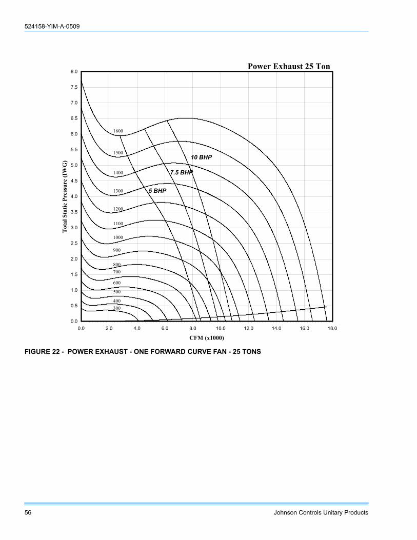
524158-YIM-A-0509
56 Johnson Controls Unitary Products
FIGURE 22 - POWER EXHAUST - ONE FORWARD CURVE FAN - 25 TONS
Power Exhaust 25 Ton
0.0
0.5
1.0
1.5
2.0
2.5
3.0
3.5
4.0
4.5
5.0
5.5
6.0
6.5
7.0
7.5
8.0
0.0 2.0 4.0 6.0 8.0 10.0 12.0 14.0 16.0 18.0
CFM (x1000)
Tot
al S
tatic
Pre
ssur
e (I
WG
)
300400
500
600
700800
900
1000
1100
1200
1300
1400
1500
1600
5 BHP
7.5 BHP
10 BHP
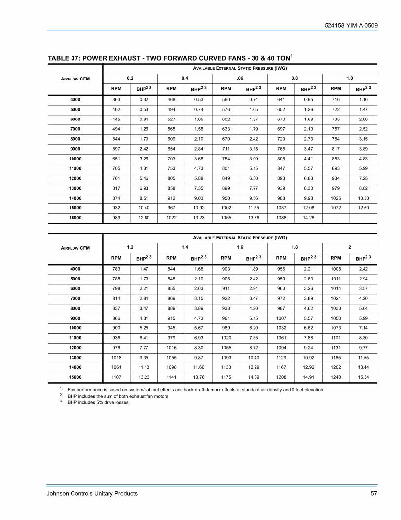
524158-YIM-A-0509
Johnson Controls Unitary Products 57
TABLE 37: POWER EXHAUST - TWO FORWARD CURVED FANS - 30 & 40 TON1
AIRFLOW CFM
AVAILABLE EXTERNAL STATIC PRESSURE (IWG)
0.2 0.4 .06 0.8 1.0
RPM BHP2 3 RPM BHP2 3 RPM BHP2 3 RPM BHP2 3 RPM BHP2 3
4000 363 0.32 468 0.53 560 0.74 641 0.95 716 1.16
5000 402 0.53 494 0.74 576 1.05 652 1.26 722 1.47
6000 445 0.84 527 1.05 602 1.37 670 1.68 735 2.00
7000 494 1.26 565 1.58 633 1.79 697 2.10 757 2.52
8000 544 1.79 609 2.10 670 2.42 729 2.73 784 3.15
9000 597 2.42 654 2.84 711 3.15 765 3.47 817 3.89
10000 651 3.26 703 3.68 754 3.99 805 4.41 853 4.83
11000 705 4.31 753 4.73 801 5.15 847 5.57 893 5.99
12000 761 5.46 805 5.88 849 6.30 893 6.83 934 7.25
13000 817 6.93 858 7.35 899 7.77 939 8.30 979 8.82
14000 874 8.51 912 9.03 950 9.56 988 9.98 1025 10.50
15000 932 10.40 967 10.92 1002 11.55 1037 12.08 1072 12.60
16000 989 12.60 1022 13.23 1055 13.76 1088 14.28 - -
AIRFLOW CFM
AVAILABLE EXTERNAL STATIC PRESSURE (IWG)
1.2 1.4 1.6 1.8 2
RPM BHP2 3 RPM BHP2 3 RPM BHP2 3 RPM BHP2 3 RPM BHP2 3
4000 783 1.47 844 1.68 903 1.89 956 2.21 1008 2.42
5000 788 1.79 848 2.10 906 2.42 959 2.63 1011 2.94
6000 798 2.21 855 2.63 911 2.94 963 3.26 1014 3.57
7000 814 2.84 869 3.15 922 3.47 972 3.89 1021 4.20
8000 837 3.47 889 3.89 938 4.20 987 4.62 1033 5.04
9000 866 4.31 915 4.73 961 5.15 1007 5.57 1050 5.99
10000 900 5.25 945 5.67 989 6.20 1032 6.62 1073 7.14
11000 936 6.41 979 6.93 1020 7.35 1061 7.88 1101 8.30
12000 976 7.77 1016 8.30 1055 8.72 1094 9.24 1131 9.77
13000 1018 9.35 1055 9.87 1093 10.40 1129 10.92 1165 11.55
14000 1061 11.13 1098 11.66 1133 12.29 1167 12.92 1202 13.44
15000 1107 13.23 1141 13.76 1175 14.39 1208 14.91 1240 15.54
1. Fan performance is based on system/cabinet effects and back draft damper effects at standard air density and 0 feet elevation.2. BHP includes the sum of both exhaust fan motors.3. BHP includes 5% drive losses.

524158-YIM-A-0509
58 Johnson Controls Unitary Products
FIGURE 23 - POWER EXHAUST - TWO FORWARD CURVED FANS - 30 & 40 TONS
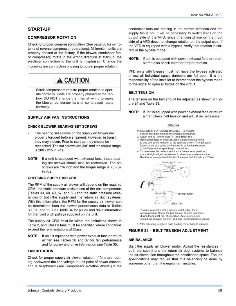
524158-YIM-A-0509
Johnson Controls Unitary Products 59
START-UP COMPRESSOR ROTATION
Check for proper compressor rotation (See page 66 for symp-toms of reverse compressor operations). Millennium units areproperly phased at the factory. If the blower, condenser fan,or compressor, rotate in the wrong direction at start-up, theelectrical connection to the unit is misphased. Change theincoming line connection phasing to obtain proper rotation.
SUPPLY AIR FAN INSTRUCTIONS
CHECK BLOWER BEARING SET SCREWS
• The bearing set screws on the supply air blower are properly torqued before shipment. However, in transit they may loosen. Prior to start up they should be rechecked. The set screws are 3/8" and the torque range is 200 - 215 in.-lbs.
NOTE: If a unit is equipped with exhaust fans, those bear-ing set screws should also be rechecked. The setscrews are 1/4 inch and the torque range is 70 - 87in.-lbs.
CHECKING SUPPLY AIR CFM
The RPM of the supply air blower will depend on the requiredCFM, the static pressure resistances of the unit components(Tables 33, 48, 49, 57, and 58) and the static pressure resis-tances of both the supply and the return air duct systems.With this information, the RPM for the supply air blower canbe determined from the blower performance data in Tables30, 31, and 32. See Table 34 for pulley and drive informationfor the fixed pitch pulleys supplied on the unit.
The supply air CFM must be within the limitations shown inTable 2, and Class II fans must be specified where conditionsexceed the rpm limitations of Class I.
NOTE: If unit is equipped with power exhaust fans or returnair fan see Tables 36 and 37 for fan performanceand for pulley and drive information see Table 35.
FAN ROTATION
Check for proper supply air blower rotation. If fans are rotat-ing backwards the line voltage to unit point of power connec-tion is misphased (see Compressor Rotation above.) If the
condenser fans are rotating in the correct direction and thesupply fan is not, it will be necessary to switch leads on theoutput side of the VFD, since changing phase on the inputside of a VFD does not change rotation on the output side. Ifthe VFD is equipped with a bypass, verify that rotation is cor-rect in the bypass mode.
NOTE: If unit is equipped with power exhaust fans or returnair fan also check them for proper rotation.
VFD units with bypass must not have the bypass activatedunless all individual space dampers are full open. It is theresponsibility of the installer to interconnect the bypass modeto the signal to open all boxes on the circuit.
BELT TENSION
The tension on the belt should be adjusted as shown in Fig-ure 24 and Table 38.
NOTE: If unit is equipped with power exhaust fans or returnair fan check belt tension and adjust as necessary.
AIR BALANCE
Start the supply air blower motor. Adjust the resistances inboth the supply and the return air duct systems to balancethe air distribution throughout the conditioned space. The jobspecifications may require that this balancing be done bysomeone other than the equipment installer.
Scroll compressors require proper rotation to oper-ate correctly. Units are properly phased at the fac-tory. DO NOT change the internal wiring to makethe blower, condenser fans or compressor rotatecorrectly.
FIGURE 24 - BELT TENSION ADJUSTMENT
� � � � � � � � � � � � � � � � � � � � � � � � � � � � � � � � � � � � � � � � � � � � � � � � � �
� � � � � � � � � � � � � � < � � � � � � � � � � � � �� � � � / / ) 2 ( � = / * 3 � > / + - ) � 5 / + 0 . ( 1 � 8 / - / 3 � > , ) 2 � - / � 4 5 , ( ( 2 + )� � � � 0 ? * ) - � > 2 + - � > : � � - * 3 ( . ( 1 � ( * - ) � � � � ) 2 2 � 0 2 - , . + � � ! �� � � � ) . ( 1 � , � > 2 + - � - 2 ( ) . / ( � 4 5 2 4 ; 2 3 @ � , 9 9 + : � , � 9 2 3 9 2 ( 0 . 4 * + , 3 � = / 3 4 2� � � � - / � / ( 2 � > 2 + - � , - � - 5 2 � 8 . 0 9 / . ( - � / = � - 5 2 � ) 9 , ( � , ) � ) 5 / 7 ( � � � 5 2 � 0 2 = + 2 4 - . / (� � � � = / 3 4 2 � ) 5 / * + 0 � > 2 � , 9 9 + . 2 0 � * ( - . + � , � ) 9 2 4 . = . 4 � 0 2 = + 2 4 - . / ( � 0 . ) - , ( 4 2� � � � / = � � % $ � � 9 2 3 � . ( 4 5 � / = � ) 9 , ( � + 2 ( 1 - 5 � . ) � / > - , . ( 2 0 �� � � � / � 0 2 - 2 3 8 . ( 2 � - 5 2 � 0 2 = + 2 4 - . / ( � 0 . ) - , ( 4 2 � = 3 / 8 � ( / 3 8 , + � 9 / ) . - . / ( @� � � � * ) 2 � , � ) - 3 , . 1 5 - � 2 0 1 2 � = 3 / 8 � ) 5 2 , A 2 � - / � ) 5 2 , A 2 � , ) � , � 3 2 = 2 3 2 ( 4 2 � + . ( 2 �� � � � � ) 2 � - 5 2 � 3 2 4 / 8 8 2 ( 0 2 0 � 0 2 = + 2 4 - . / ( � = / 3 4 2 � 9 2 3 � � 2 + - � � 0 ? * ) - 8 2 ( - � � , > + 2 �
" � � � = - 2 3 � , 0 ? * ) - . ( 1 @ � 3 2 - . 1 5 - 2 ( � > / + - ) � 5 / + 0 . ( 1 � 8 / - / 3 � > , ) 2 � - / � 4 5 , ( ( 2 + �
� 2 ( ) . / ( � ( 2 7 � > 2 + - ) � , - � - 5 2 � 8 , B . 8 * 8 � 0 2 = + 2 4 - . / ( � = / 3 4 23 2 4 / 8 8 2 ( 0 2 0 � � � 5 2 4 ; � - 5 2 � > 2 + - � - 2 ( ) . / ( � , - � + 2 , ) - � - 7 / � - . 8 2 )0 * 3 . ( 1 � - 5 2 � = . 3 ) - � � � � 5 3 ) � � / = � / 9 2 3 , - . / ( � � � ( : � 3 2 ' - 2 ( ) . / ( . ( 1) 5 / * + 0 � = , + + � > 2 - 7 2 2 ( � - 5 2 � 8 . ( � � , ( 0 � 8 , B � � 0 2 = + 2 4 - . / ( � = / 3 4 2 � A , + * 2 ) �
�
� � � � � � � �
� � � � � �
� � � � � � � � �
� � � � � � �� � � � � � � � � �

524158-YIM-A-0509
60 Johnson Controls Unitary Products
CHECKING AIR QUANTITY
1. Remove the dot plugs from the two 5/16 inch holes in the blower motor and the filter access doors.
2. Insert at least 8 inch of 1/4 inch metal tubing into each of these holes for sufficient penetration into the air flow on both sides of the indoor coil.
3. Using an inclined manometer or other high resolution pressure measurement device, determine the pressure drop across a dry evaporator coil. Since the moisture on an evaporator coil may vary greatly, measuring the pres-sure drop across a wet coil under field conditions would be inaccurate. To assure a dry coil, the compressors should be de-activated while the test is being run.
4. Knowing the pressure drop across a dry coil, the actual CFM through the unit with clean 2 inch filters, can be determined from the curve in Figure 52 and 53.
NOTE: De-energize the compressors before taking any testmeasurements to assure a dry evaporator coil.
After readings have been obtained, remove the tubes andreinstall the two 5/16 inch dot plugs.
It is especially important to limit the rpm of the fan in VFD-bypass-equipped units; it may be tempting to set max rpm inthe VFD to less than 60 Hz - but the bypass will go to 60 Hzimmediately on activation.
On VAV and VFD units be certain all IGV’s on VAVunit are full open, VFD drive is set to maximumoutput, exhaust dampers are closed and individualspace damper boxes are full open.
VFD units with bypass must not have the bypassactivated unless all individual space dampers arefull open.
TABLE 38: BELT ADJUSTMENT
FAN MOTOR HORSE POWER 5 7.5 10 15 20 25
30 TON FORWARD CURVED SUPPLY FAN SIZE: 22 X 20
Belt Deflection Force (lbs) new belts - - 10.5 12.6 15.2 22.1
Belt Deflection Force (lbs) old belts - - 7.1 8.5 10.2 14.8
40 TON FORWARD CURVED SUPPLY FAN SIZE: 25 X 20
Belt Deflection Force (lbs) new belts - - 10.5 12.6 15.2 15.2
Belt Deflection Force (lbs) old belts - - 7.1 8.5 10.2 10.2
30 & 40 TON POWER EXHAUST FAN SIZE: (2) 15 X 15
Belt Deflection Force (lbs) new belts - 7.9 9.4 9.4 - -
Belt Deflection Force (lbs) old belts - 5.3 6.3 6.3 - -
25 TON FORWARD CURVE SUPPLY FAN SIZE: 22 X 20
New Belt - 10.5 10.5 12.6 15.2 -
Old Belt - 7.1 7.1 8.5 10.2 -
25 TON POWER EXHAUST
New Belt 10.5 10.5 12.6 - - -
Old Belt 7.1 7.1 8.5 - - -
Failure to properly adjust the total system air quan-tity can result in extensive blower or duct damage.

524158-YIM-A-0509
Johnson Controls Unitary Products 61
SUPPLY AIR DRIVE ADJUSTMENT
At unit start-up the measured CFM based on Figures 52 and53 may be higher or lower than the specified CFM. Toachieve the specified CFM, the speed of the drive may haveto be decreased or increased by changing the pitch diameter(PD) of the motor sheave as outlined below:
• (Specified CFM/Measured CFM) X PD of standard sheave = PD of new sheave.
Use the following tables and the PD calculated per the aboveequation to select a new motor sheave.
EXAMPLE
• A 30 ton unit was selected to deliver 12,000 CFM with a 20 HP motor and a 856 RPM drive, but the unit is only delivering 11,000 CFM per Figure 20.
• Use the equation to determine the required PD for the new motor sheave (12,000 CFM/11,000 CFM X 6.7” = 7.3091 inch).
• Use the 30 ton table to select a Browning 2B5V74 which will increase the speed of the unit’s drive and its supply air CFM to 111.9%. Thus select the 7.5” PD at 112% increase over standard.
• New drive speed = 1.1194 X 856 = 958.2 RPM
• New supply air = 1.1194 X 11,000 = 12,313 CFM
• Re-use the existing belts and blower sheave.
New motor BHP = (speed increase)3 x estimated motorBHP at original start-up with 11,000 CFM and 856 RPM =(1.119)3 x 11 BHP = 1.4012 x 11 BHP = 15.41 BHP Newmotor amps = (speed increase)3 x measured motor ampsat original start-up with 11,000 CFM and 856 RPM.
.
SYSTEM SETPOINTS
Constant Volume and Variable Air Volume:
Thermostat and space sensor offsets must be made externalto the unit. For internal settings, refer to the Settable Parame-ters in the Unit Control document. All parameters affectingthe unit with that specific set of options and for that specificapplication must be reviewed. In many cases, the default set-tings will be fine - but verify and fine tune where necessary.
Before making any blower speed changes reviewthe installation for any installation errors, leaks orundesirable systems effects that can result in lossof air flow.
Even small changes in blower speed can result insubstantial changes in static pressure and BHP.BHP or AMP draw of the blower motor willincrease (see table 39) by the cube ratio of theblower speed. Static pressure will increase by thesquare ratio of the blower speed. Tables 40, 41and 42 are for reference only. All blower speedchanges must be made by qualified personnel withstrict adherence to the fan laws.
TABLE 39: BLOWER SPEED RATE OF CHANGE
CHANGE IN RPM
CHANGE IN
CFM TSPBHP AND MOTOR AMPS
.90 .90 .81 .73
.93 .93 .86 .79
.95 .95 .90 .86
.98 .98 .95 .93
1.00 1.00 1.00 1.00
1.03 1.03 1.05 1.08
1.05 1.05 1.10 1.16
1.08 1.08 1.16 1.24
1.10 1.10 1.21 1.33
1.13 1.13 1.27 1.42
1.15 1.15 1.32 1.52
1.18 1.18 1.38 1.62
1.20 1.20 1.44 1.73
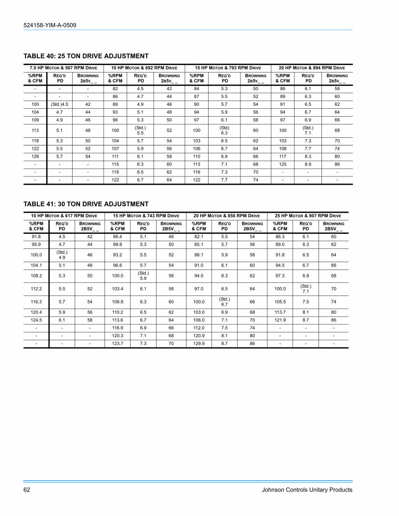
524158-YIM-A-0509
62 Johnson Controls Unitary Products
TABLE 40: 25 TON DRIVE ADJUSTMENT7.5 HP MOTOR & 567 RPM DRIVE 10 HP MOTOR & 692 RPM DRIVE 15 HP MOTOR & 793 RPM DRIVE 20 HP MOTOR & 894 RPM DRIVE
%RPM& CFM
REQ’D PD
BROWNING 2B5V_ _
%RPM& CFM
REQ’D PD
BROWNING 2B5V_ _
%RPM& CFM
REQ’D PD
BROWNING 2B5V_ _
%RPM & CFM
REQ’D PD
BROWNING 2B5V_ _
- - - 82 4.5 42 84 5.3 50 86 6.1 58
- - - 86 4.7 44 87 5.5 52 89 6.3 60
100 (Std.)4.5 42 89 4.9 46 90 5.7 54 91 6.5 62
104 4.7 44 93 5.1 48 94 5.9 56 94 6.7 64
109 4.9 46 96 5.3 50 97 6.1 58 97 6.9 66
113 5.1 48 100 (Std.)5.5 52 100 (Std)
6.3 60 100 (Std.)7.1 68
118 5.3 50 104 5.7 54 103 6.5 62 103 7.3 70
122 5.5 52 107 5.9 56 106 6.7 64 108 7.7 74
126 5.7 54 111 6.1 58 110 6.9 66 117 8.3 80
- - - 115 6.3 60 113 7.1 68 125 8.9 86
- - - 118 6.5 62 116 7.3 70 - - -
- - - 122 6.7 64 122 7.7 74 - - -
TABLE 41: 30 TON DRIVE ADJUSTMENT10 HP MOTOR & 617 RPM DRIVE 15 HP MOTOR & 743 RPM DRIVE 20 HP MOTOR & 856 RPM DRIVE 25 HP MOTOR & 907 RPM DRIVE
%RPM& CFM
REQ’D PD
BROWNING2B5V_ _
%RPM& CFM
REQ’D PD
BROWNING2B5V_ _
%RPM& CFM
REQ’D PD
BROWNING2B5V_ _
%RPM & CFM
REQ’D PD
BROWNING2B5V_ _
91.8 4.5 42 86.4 5.1 48 82.1 5.5 54 86.3 6.1 60
95.9 4.7 44 89.8 5.3 50 85.1 5.7 56 89.0 6.3 62
100.0 (Std.)4.9 46 93.2 5.5 52 88.1 5.9 58 91.8 6.5 64
104.1 5.1 48 96.6 5.7 54 91.0 6.1 60 94.5 6.7 66
108.2 5.3 50 100.0 (Std.)5.9 56 94.0 6.3 62 97.3 6.9 68
112.2 5.5 52 103.4 6.1 58 97.0 6.5 64 100.0 (Std.) 7.1 70
116.3 5.7 54 106.8 6.3 60 100.0 (Std.) 6.7 66 105.5 7.5 74
120.4 5.9 56 110.2 6.5 62 103.0 6.9 68 113.7 8.1 80
124.5 6.1 58 113.6 6.7 64 106.0 7.1 70 121.9 8.7 86
- - - 116.9 6.9 66 112.0 7.5 74 - - -
- - - 120.3 7.1 68 120.9 8.1 80 - - -
- - - 123.7 7.3 70 129.9 8.7 86 - - -

524158-YIM-A-0509
Johnson Controls Unitary Products 63
TABLE 42: 40 TON DRIVE ADJUSTMENT10 HP MOTOR & 617 RPM DRIVE 15 HP MOTOR & 652 RPM DRIVE 20 HP MOTOR & 728 RPM DRIVE 25 HP MOTOR & 780 RPM DRIVE
%RPM & CFM
REQ’D PD
BROWNING2B5V_ _
% RPM & CFM
REQ’D PD
BROWNING2B5V_ _
%RPM & CFM
REQ’D PD
BROWNING 2B5V_ _
%RPM & CFM
REQ’D PD
BROWNING2B5V_ _
91.8 4.5 42 88.2 4.5 44 82.5 4.7 46 83.7 5.1 50
95.9 4.7 44 92.1 4.7 46 86.0 4.9 48 86.9 5.3 52
100.0 (Std.) 4.9 46 96.0 4.9 48 89.5 5.1 50 90.2 5.5 54
104.1 5.1 48 100.0 (Std.)5.1 50 93.0 5.3 52 93.4 5.7 56
108.2 5.3 50 103.9 5.3 52 96.5 5.5 54 96.7 5.9 58
112.2 5.5 52 107.8 5.5 54 100.0 (Std.)5.7 56 100.0 (Std.)
6.1 60
116.3 5.7 54 111.7 5.7 56 103.5 5.9 58 103.3 6.3 62
- - - 115.6 5.9 58 107.0 6.1 60 106.6 6.5 64
- - - 119.5 6.1 60 110.5 6.3 62 109.8 6.7 66
- - - 123.4 6.3 62 114.0 6.5 64 113.1 6.9 68
- - - 127.4 6.5 64 117.5 6.7 66 116.4 7.1 70
- - - - - 66 121.1 6.9 68 119.7 7.5 74
TABLE 43: DRIVE ADJUSTMENT FOR POWER EXHAUST - 25 TON
5 HP Motor & 758 RPM Drive 7.5 HP Motor & 852 RPM Drive 10 HP Motor & 976 RPM Drive
%RPM& CFM
Req’dPD
Browning 2b5v_ _
%RPM& CFM
Req’dPD
Browning 2b5v_ _
%RPM& CFM Req’d PD Browning
2b5v_ _
100 4.9 (Std.) 46 92 5.1 48 93 5.9 56104 5.1 48 96 5.3 50 97 6.1 58109 5.3 50 100 5.5 (Std.) 52 100 6.3 (Std.) 60113 5.5 52 104 5.7 54 103 6.5 62117 5.7 54 108 5.9 56 107 6.7 64122 5.9 56 112 6.1 58 110 6.9 66

524158-YIM-A-0509
64 Johnson Controls Unitary Products
GAS FURNACE OPERATINGINSTRUCTIONS
TO LIGHT THE MAIN BURNERS
1. Turn off electric power to unit.
2. Turn space temperature sensor to lowest setting.
3. Turn gas valve knobs to on position (Refer to Figure 25).
4. Turn on electric power to unit.
5. On Constant Volume units, set space setpoint to warmer or cooler as desired. (If sensor set point temperature is above room temperature, the main burners will ignite). If a second stage of heat is called for, the main burners for second stage heat will ignite for the second stage heat. For VAV units set morning warm-up thermostat far above the return air temperature and cycle the time clock OFF, then ON.
TO SHUT DOWN
1. Turn off electric power to unit.
2. Depress knob of gas valve while turning to off position or move switch to off position. (Refer to Figure 25).
POST-START CHECKLIST (GAS)
After the entire control circuit has been energized and theheating section is operating, make the following checks:
1. Check for gas leaks in the unit piping as well as the sup-ply piping.
2. Check for correct manifold gas pressures. See Checking Gas Input.
3. Check the supply gas pressure. It must be within the lim-its shown on rating nameplate. Supply pressure should be checked with all gas appliances in the building at full fire. At no time should the standby gas pressure exceed 13 inches, nor the operating pressure drop below 6 inches. If gas pressure is outside these limits, contact the local gas utility for corrective action.
MANIFOLD GAS PRESSURE ADJUSTMENT
Small adjustments to the gas flow may be made by turningthe pressure regulator adjusting screw on the automatic gasvalve. Refer to Figure 25.
Adjust as follows:
1. Remove the cap on the regulator. It's located next to the push-on electrical terminals.
2. To decrease the gas pressure, turn the adjusting screw counterclockwise.
3. To increase the gas pressure, turn the adjusting screw clockwise.
NOTE: The factory manifold pressure for each furnacemodule is 3.50 IWG.
TABLE 44: DRIVE ADJUSTMENT FOR POWER EXHAUST - 30 & 40 TON
7.5 HP Motor & 852 RPM Drive 10 HP Motor & 976 RPM Drive 15 HP Motor & 1069 RPM Drive
% RPM& CFM
REQ’DPD (in)
Browning2B5V_ _
% RPM& CFM
REQ’DPD (in)
Browning2B5V_ _
% RPM& CFM
REQ’DPD (in)
Browning2B5V_ _
96.4 5.3 52 93.7 5.9 58 94.2 6.5 64100.0 (Std.) 5.5 54 96.8 6.1 60 97.1 6.7 66103.6 5.7 56 100.0 (Std.) 6.3 62 100.0 (Std.) 6.9 68107.3 5.9 58 103.2 6.5 64 102.9 7.1 70110.9 6.1 60 106.3 6.7 66 108.7 7.5 74114.5 6.3 62 109.5 6.9 68 117.4 8.1 80
Each furnace module is equipped with an auto-matic re-ignition system. DO NOT attempt to man-ually light the burners.

524158-YIM-A-0509
Johnson Controls Unitary Products 65
BURNER INSTRUCTIONS
To check or change burners, pilot or orifices, CLOSE MAINMANUAL SHUT-OFF VALVE AND SHUT OFF ALL POWERTO THE UNIT.
1. Remove the screws holding either end of the manifold to the burner supports.
2. Open the union fitting in the gas supply line just upstream of the unit gas valves and downstream from the main manual shut-off valve.
3. Disconnect wiring to the gas valves and spark ignitors. Remove the manifold-burner gas valve assemblies by pulling back.
4. Remove the heat shield on top of the manifold support.
Burners are now accessible for service.
Reverse the above procedure to replace the assemblies.Make sure that burners are level and seat at the rear of thegas orifice.
ADJUSTMENT OF TEMPERATURE RISE
The temperature rise (or temperature difference between thereturn air and the heated air from the furnace) must lie withinthe range shown on the CGA/ETL rating plate and the data inTable 3.
After the temperature rise has been determined, the CFM canbe calculated as follows:
After about 20 minutes of operation, determine the furnacetemperature rise. Take readings of both the return air and theheated air in the ducts (about six feet from the furnace) wherethey will not be affected by radiant heat. Increase the blowerCFM to decrease the temperature rise; decrease the blowerCFM to increase the rise. Refer to Table 34 for supply airblower motor and drive data. Minimum allowable CFM is6,000 CFM. Limit will open below this rating.
CHECKING GAS INPUT
NATURAL GAS
1. Turn off all other gas appliances connected to the gas meter.
2. With the furnace turned on, measure the time needed for one revolution of the hand on the smallest dial on the meter. A typical gas meter usually has a 1/2 or a 1 cubic foot test dial.
3. Using the number of seconds for each revolution and the size of the test dial increment, find the cubic feet of gas consumed per hour from Table 45.
If the actual input is not within 5% of the furnace rating (withallowance being made for the permissible range of the regu-lator setting), replace the orifice spuds with spuds of theproper size.
NOTE: To find the Btu input, multiply the number of cubicfeet of gas consumed per hour by the Btu content ofthe gas in your particular locality (contact your gascompany for this information - it varies widely fromcity to city).
FIGURE 25 - TYPICAL GAS VALVES
VALVESWITCH
VALVEINLET
ELECTRICALTERMINALS
STANDARD GAS VALVE
VALVESWITCH
VALVEINLET
ELECTRICALTERMINALS
MODULATING GAS VALVE
CFM Btuh 0.8×1.08 F Degrees Temp Rise×--------------------------------------------------------------------------=

524158-YIM-A-0509
66 Johnson Controls Unitary Products
Example: By actual measurement, it takes 7 seconds for thehand on the one cubic foot dial to make a revolution with justa 570,000 Btuh furnace running. Read across to the columnin Table 24, headed 1 Cubic Foot where you will determinethat 525 cubic feet of gas per hour are consumed by the fur-nace at that rate. Multiply 525 x 1050 (the Btu rating of thegas obtained from the local gas company). The result of551,000 Btuh is within 5% of the 570,000 Btuh rating of thefurnace.
ELECTRIC HEATING
The electric furnace is operational as shipped from the fac-tory and does not receive any field adjustments.
COOLING OPERATING INSTRUCTIONS
COMPRESSOR
Compressors are factory mounted ready for operation (Seepage 59 Compressor Rotation).
INTERNAL WIRING
Check all electrical connections in the unit control box;tighten as required.
CONDENSER FANS
Check for proper condenser fan rotation; clockwise facing theair discharge. If condenser fans are rotating backwards, linevoltage to unit single point power connection is misphased(See page 59 Compressor Rotation).
SERVICE
REFRIGERATION SYSTEM
CHARGE: Each system is fully factory charged with R-410A.The correct charge appears on the unit nameplate.
Thermal Expansion Valves: The 30 ton unit has 3 and the 40ton unit has 4 independent refrigeration systems. TheseTXVs are set to maintain 15°F superheat leaving the evapo-rator coil. The superheat on each valve is adjustable, how-ever, adjustments should only be made if absolutelynecessary.
FILTER DRIER: Each system is equipped with a filter drier.The drier should be replaced whenever moisture is indicatedin the system.
COMPRESSORS
Each compressor is inherently protected from over currentand over temperature. High and low pressure switches areinstalled on the discharge and suction lines respectively forhigh and low pressure protection. Scroll compressors operatein only one direction. If the compressor is experiencing lowamperage draw, similar discharge and suction pressure orincreased noise level, it is operating in reverse. Switch twoline voltage connections to correct (See Compressor Rotationpage 59).
MOTORS
INDOOR BLOWER MOTORS
All indoor blower motors are non-inherently protected threephase motors. Overcurrent protection is provided by a man-ual reset starter/overload relay and short circuit protection isprovided by fuses. Where there is a supply fan VFD, an auxil-iary contact provides the overcurrent indication to the Sim-plicity® control.
POWER EXHAUST OR RETURN AIR FAN MOTORS
All motors are non-inherently protected three phase motors.Overcurrent protection is provided by a manual resetstarter/overload relay and short circuit protection is providedby fuses.
CONDENSER FAN MOTORS
All condenser fan motors are inherently protected threephase motors. Short circuit protection is provided by fuses.
DRAFT MOTOR (GAS FURNACE)
All draft motors are line voltage, inherently protected, singlephase PSC motors. Short circuit protection is provided byfuses.
TABLE 45: GAS RATE - CUBIC FEET PER HOUR
Seconds for One Rev.
Size of Test Dial
1/2 cu. Ft. 1 cu. Ft.
2 900 1800
4 450 900
6 300 600
8 225 450
10 180 360
FIGURE 26 - TYPICAL FLAME APPEARANCE
� � � � � � �� �
� � � � �
� � � � � � � � � � C � � � � � �
� � � � � � � � � � � � � � � � � � � !
� � � � D � � � � � � � � � �

524158-YIM-A-0509
Johnson Controls Unitary Products 67
TABLE 46: STEAM COIL (1 ROW, 25 & 30 TON)1
CFMCapacity (MBH) at Steam Pressure (PSI)
2 6 10 15
6000 194.1 207.9 219.8 232.6
8000 221.1 236.9 250.4 265.0
10000 243.2 260.5 275.4 291.4
12000 261.9 280.6 296.6 313.9
15000 285.6 306.0 323.5 342.4
1. Based on 60°F entering air temperature, 2.00” maxi-mum air pressure drop across the coil.
TABLE 47: STEAM COIL (1 ROW, 40 TON)1
1. Based on 60°F entering air temperature, 2.00” maxi-mum air pressure drop across the coil.
CFMCapacity (MBH) at Steam Pressure (PSI)
2 6 10 15
8000 221.1 236.9 250.4 265.0
11000 252.9 271.0 286.4 303.1
14000 278.2 298.0 315.0 333.4
17000 299.4 320.7 339.0 358.8
20000 317.6 340.2 359.6 380.6
TABLE 48: STATIC RESISTANCE STEAM COIL (25 & 30 TON)
CFM 6000 8000 10000 12000 15000
Air Pressure Drop 0.11 0.18 0.26 0.36 0.54
TABLE 49: STATIC RESISTANCE STEAM COIL (40 TON)
CFM 8000 11000 14000 17000 20000
Air Pressure Drop 0.18 0.31 0.48 0.67 0.88
TABLE 50: HOT WATER COIL (1 ROW 25 & 30 TON)1
1. Based on 60°F entering air temperature, 2.00” maximum pressure drop across the hot water coil.
GPM CFM
Capacity (MBH) at Entering Water Temperature
140 °F 160 °F 180 °F 200 °F
10
6000 91.4 115.3 139.3 163.6
8000 102 128.8 155.8 182.9
10000 110.4 139.5 168.8 198.4
12000 117.3 148.4 179.6 211.2
15000 125.9 159.2 192.9 226.9
20
6000 103 129.4 156 182.7
8000 116.8 147 177.2 207.7
10000 128.2 161.3 194.7 228.2
12000 137.8 173.6 209.5 245.6
15000 150 189 228.2 267.8
30
6000 107.6 135 162.5 190.1
8000 122.8 154.3 185.8 217.5
10000 135.5 170.3 205.1 240.2
12000 146.4 184 221.8 259.7
15000 160.3 201.6 243 284.8
40
6000 110.1 138 166 194.1
8000 126.1 158.2 190.5 222.8
10000 139.6 175.2 210.9 246.8
12000 151.2 189.8 228.5 267.5
15000 166.1 208.6 251.3 294.1
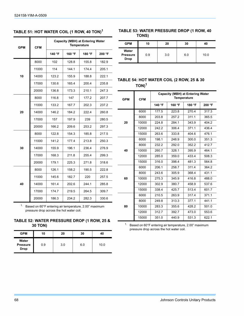
524158-YIM-A-0509
68 Johnson Controls Unitary Products
TABLE 51: HOT WATER COIL (1 ROW, 40 TON)1
1. Based on 60°F entering air temperature, 2.00” maximum pressure drop across the hot water coil.
GPM CFM
Capacity (MBH) at Entering Water Temperature
140 °F 160 °F 180 °F 200 °F
10
8000 102 128.8 155.8 182.9
11000 114 144.1 174.4 205.1
14000 123.2 155.9 188.8 222.1
17000 130.6 165.4 200.4 235.8
20000 136.8 173.3 210.1 247.3
20
8000 116.8 147 177.2 207.7
11000 133.2 167.7 202.3 237.2
14000 146.2 184.2 222.4 260.8
17000 157 197.9 239 280.5
20000 166.2 209.6 253.2 297.3
30
8000 122.8 154.3 185.8 217.5
11000 141.2 177.4 213.8 250.3
14000 155.9 196.1 236.4 276.9
17000 168.3 211.8 255.4 299.3
20000 179.1 225.3 271.8 318.6
40
8000 126.1 158.2 190.5 222.8
11000 145.6 182.7 220 257.5
14000 161.4 202.6 244.1 285.8
17000 174.7 219.5 264.5 309.7
20000 186.3 234.2 282.3 330.6
TABLE 52: WATER PRESSURE DROP (1 ROW, 25 & 30 TON)
GPM 10 20 30 40
Water Pressure
Drop0.9 3.0 6.0 10.0
TABLE 53: WATER PRESSURE DROP (1 ROW, 40 TONS)
GPM 10 20 30 40
Water Pressure
Drop0.9 3.0 6.0 10.0
TABLE 54: HOT WATER COIL (2 ROW, 25 & 30 TON)1
1. Based on 60°F entering air temperature, 2.00” maximum pressure drop across the hot water coil.
GPM CFM
Capacity (MBH) at Entering Water Temperature
140 °F 160 °F 180 °F 200 °F
20
6000 177.5 223.8 270.4 317.3
8000 203.8 257.2 311.1 365.5
10000 224.8 284.1 343.9 404.2
12000 242.2 306.4 371.1 436.4
15000 263.6 333.8 404.6 476.1
40
6000 198.1 248.9 300.0 351.3
8000 232.2 292.0 352.2 412.7
10000 260.7 328.1 395.9 464.1
12000 285.0 359.0 433.4 508.3
15000 316.0 398.4 481.3 564.8
60
6000 206.1 258.7 311.4 364.2
8000 243.6 305.9 368.4 431.1
10000 275.3 345.9 416.8 488.0
12000 302.9 380.7 458.9 537.6
15000 338.4 425.7 513.4 601.7
80
6000 210.5 263.9 317.4 371.1
8000 249.8 313.3 377.1 441.1
10000 283.3 355.6 428.2 501.0
12000 312.7 392.7 473.0 553.6
15000 351.0 440.9 531.3 622.1

524158-YIM-A-0509
Johnson Controls Unitary Products 69
NOTE: Water pressure drop numbers are based on 60°Fentering air temperature, 2.00” maximum air pres-sure drop across the hot water coil(s). ARI certifiedratings at covering other conditions are availableupon request. Hot water coils are approved for usewith glycol (rates available upon request.
TABLE 55: WATER PRESSURE DROP (2 ROW, 25 & 30 TON)
GPM 20 40 60 80
Water Pressure
Drop0.9 3.0 6.0 10.0
TABLE 56: WATER PRESSURE DROP (2 ROW, 40 TON)
GPM 20 40 60 80
Water Pressure
Drop0.9 3.0 6.0 10.0
TABLE 57: STATIC RESISTANCE HOT WATER COIL (25 & 30 TON)
CFM 6000 8000 10000 15000
Air Pressure Drop 1 Row 0.07 0.11 0.16 0.32
Air Pressure Drop 2 Row 0.14 0.23 0.33 0.65
TABLE 58: STATIC RESISTANCE HOT WATER COIL (40 TON)
CFM 8000 11000 14000 20000
Air Pressure Drop 1 Row 0.11 0.19 0.29 0.52
Air Pressure Drop 2 Row 0.23 0.39 0.58 1.06

524158-YIM-A-0509
70 Johnson Controls Unitary Products
FIGURE 27 - HOT WATER COIL - 25 & 30 TON, 1 ROW, AT 10 GPM
8 0 .0
9 0 .0
1 0 0 .0
1 1 0 .0
1 2 0 .0
1 3 0 .0
1 4 0 .0
1 5 0 .0
1 6 0 .0
1 7 0 .0
1 8 0 .0
1 9 0 .0
2 0 0 .0
2 1 0 .0
2 2 0 .0
2 3 0 .0
6 0 0 0 7 0 0 0 8 0 0 0 9 0 0 0 1 0 0 0 0 1 1 0 0 0 1 2 0 0 0 1 3 0 0 0 1 4 0 0 0 1 5 0 0 0
F L O W R A T E (C F M )
CA
PAC
ITY
(MB
H)
1 4 0 ° F1 6 0 ° F1 8 0 ° F2 0 0 ° F
FIGURE 28 - HOT WATER COIL - 25 & 30 TON, 1 ROW, AT 20 GPM
9 0 .0
1 0 0 .0
1 1 0 .0
1 2 0 .0
1 3 0 .0
1 4 0 .0
1 5 0 .0
1 6 0 .0
1 7 0 .0
1 8 0 .0
1 9 0 .0
2 0 0 .0
2 1 0 .0
2 2 0 .0
2 3 0 .0
2 4 0 .0
2 5 0 .0
2 6 0 .0
2 7 0 .0
6 0 0 0 7 0 0 0 8 0 0 0 9 0 0 0 1 0 0 0 0 1 1 0 0 0 1 2 0 0 0 1 3 0 0 0 1 4 0 0 0 1 5 0 0 0
F L O W R A T E (C F M )
CA
PAC
ITY
(MB
H)
1 4 0 °F1 6 0 °F1 8 0 °F2 0 0 °F

524158-YIM-A-0509
Johnson Controls Unitary Products 71
FIGURE 29 - HOT WATER COIL - 25 & 30 TON, 1 ROW, AT 30 GPM
1 0 0 .0
1 1 0 .0
1 2 0 .0
1 3 0 .0
1 4 0 .0
1 5 0 .0
1 6 0 .0
1 7 0 .0
1 8 0 .0
1 9 0 .0
2 0 0 .0
2 1 0 .0
2 2 0 .0
2 3 0 .0
2 4 0 .0
2 5 0 .0
2 6 0 .0
2 7 0 .0
2 8 0 .0
2 9 0 .0
6 0 0 0 7 0 0 0 8 0 0 0 9 0 0 0 1 0 0 0 0 1 1 0 0 0 1 2 0 0 0 1 3 0 0 0 1 4 0 0 0 1 5 0 0 0
F L O W R A T E (C F M )
CA
PAC
ITY
(MB
H)
1 4 0 ° F1 6 0 ° F1 8 0 ° F2 0 0 ° F
FIGURE 30 - HOT WATER COIL - 25 & 30 TON, 1 ROW, AT 40 GPM
180.0
200.0
220.0
240.0
260.0
280.0
300.0
320.0
340.0
360.0
380.0
400.0
420.0
440.0
460.0
480.0
500.0
520.0
540.0
560.0
580.0
6000 7000 8000 9000 10000 11000 12000 13000 14000 15000
F L O W R AT E (C F M )
CA
PAC
ITY
(MB
H)
140 °F160 °F180 °F200 °F

524158-YIM-A-0509
72 Johnson Controls Unitary Products
FIGURE 31 - HOT WATER COIL - 25 & 30 TON, 2 ROW, AT 60 GPM
190 .0
210 .0
230 .0
250 .0
270 .0
290 .0
310 .0
330 .0
350 .0
370 .0
390 .0
410 .0
430 .0
450 .0
470 .0
490 .0
510 .0
530 .0
550 .0
570 .0
590 .0
610 .0
60 00 7000 8 000 9000 1 0000 110 00 1200 0 130 00 1400 0 15 000
F L O W R A T E (C F M )
CA
PAC
ITY
(MB
H)
140 °F160 °F180 °F200 °F
FIGURE 32 - HOT WATER COIL - 25 & 30 TON, 2 ROW, AT 80 GPM
2 0 0 .0
2 2 0 .0
2 4 0 .0
2 6 0 .0
2 8 0 .0
3 0 0 .0
3 2 0 .0
3 4 0 .0
3 6 0 .0
3 8 0 .0
4 0 0 .0
4 2 0 .0
4 4 0 .0
4 6 0 .0
4 8 0 .0
5 0 0 .0
5 2 0 .0
5 4 0 .0
5 6 0 .0
5 8 0 .0
6 0 0 .0
6 2 0 .0
6 4 0 .0
6 0 0 0 7 0 0 0 8 0 0 0 9 0 0 0 1 0 0 0 0 1 1 0 0 0 1 2 0 0 0 1 3 0 0 0 1 4 0 0 0 1 5 0 0 0
F L O W R A T E (C F M )
CA
PAC
ITY
(MB
H)
1 4 0 °F1 6 0 °F1 8 0 °F2 0 0 °F

524158-YIM-A-0509
Johnson Controls Unitary Products 73
FIGURE 33 - HOT WATER COIL - 40 TON, 1 ROW, AT 10 GPM
90 .0
100 .0
110 .0
120 .0
130 .0
140 .0
150 .0
160 .0
170 .0
180 .0
190 .0
200 .0
210 .0
220 .0
230 .0
240 .0
250 .0
8000 9000 10000 11000 12000 13000 14000 15000 16000 17000 18000 19000 20000
F L O W R AT E (C F M )
CA
PAC
ITY
(MB
H)
140 °F160 °F180 °F200 °F
FIGURE 34 - HOT WATER COIL - 40 TON, 1 ROW, AT 20 GPM
1 0 0 .0
1 1 0 .0
1 2 0 .0
1 3 0 .0
1 4 0 .0
1 5 0 .0
1 6 0 .0
1 7 0 .0
1 8 0 .0
1 9 0 .0
2 0 0 .0
2 1 0 .0
2 2 0 .0
2 3 0 .0
2 4 0 .0
2 5 0 .0
2 6 0 .0
2 7 0 .0
2 8 0 .0
2 9 0 .0
3 0 0 .0
8 0 0 0 9 0 0 0 1 0 0 0 0 1 1 0 0 0 1 2 0 0 0 1 3 0 0 0 1 4 0 0 0 1 5 0 0 0 1 6 0 0 0 1 7 0 0 0 1 8 0 0 0 1 9 0 0 0 2 0 0 0 0
F L O W R A T E (C F M )
CA
PAC
ITY
(MB
H)
1 4 0 °F1 6 0 °F1 8 0 °F2 0 0 °F
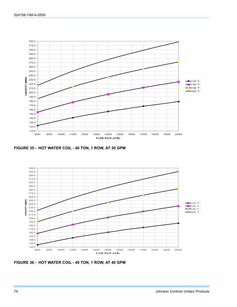
524158-YIM-A-0509
74 Johnson Controls Unitary Products
FIGURE 35 - HOT WATER COIL - 40 TON, 1 ROW, AT 30 GPM
110.0
120.0
130.0
140.0
150.0
160.0
170.0
180.0
190.0
200.0
210.0
220.0
230.0
240.0
250.0
260.0
270.0
280.0
290.0
300.0
310.0
320.0
8000 9000 10000 11000 12000 13000 14000 15000 16000 17000 18000 19000 20000
FLOW RATE (CFM )
CA
PAC
ITY
(MB
H)
140 °F160 °F180 °F200 °F
FIGURE 36 - HOT WATER COIL - 40 TON, 1 ROW, AT 40 GPM
1 2 0 .0
1 3 0 .0
1 4 0 .0
1 5 0 .0
1 6 0 .0
1 7 0 .0
1 8 0 .0
1 9 0 .0
2 0 0 .0
2 1 0 .0
2 2 0 .0
2 3 0 .0
2 4 0 .0
2 5 0 .0
2 6 0 .0
2 7 0 .0
2 8 0 .0
2 9 0 .0
3 0 0 .0
3 1 0 .0
3 2 0 .0
3 3 0 .0
3 4 0 .0
8 0 0 0 9 0 0 0 1 0 0 0 0 1 1 0 0 0 1 2 0 0 0 1 3 0 0 0 1 4 0 0 0 1 5 0 0 0 1 6 0 0 0 1 7 0 0 0 1 8 0 0 0 1 9 0 0 0 2 0 0 0 0
F L O W R A T E (C F M )
CA
PAC
ITY
(MB
H)
1 4 0 °F1 6 0 °F1 8 0 °F2 0 0 °F
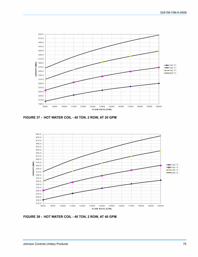
524158-YIM-A-0509
Johnson Controls Unitary Products 75
FIGURE 37 - HOT WATER COIL - 40 TON, 2 ROW, AT 20 GPM
FIGURE 38 - HOT WATER COIL - 40 TON, 2 ROW, AT 40 GPM
190.0
210.0
230.0
250.0
270.0
290.0
310.0
330.0
350.0
370.0
390.0
410.0
430.0
450.0
470.0
490.0
510.0
530.0
8000 9000 10000 11000 12000 13000 14000 15000 16000 17000 18000 19000 20000
F LO W R AT E (C FM )
CA
PAC
ITY
(MB
H)
140 °F160 °F180 °F200 °F
2 1 0 .0
2 3 0 .0
2 5 0 .0
2 7 0 .0
2 9 0 .0
3 1 0 .0
3 3 0 .0
3 5 0 .0
3 7 0 .0
3 9 0 .0
4 1 0 .0
4 3 0 .0
4 5 0 .0
4 7 0 .0
4 9 0 .0
5 1 0 .0
5 3 0 .0
5 5 0 .0
5 7 0 .0
5 9 0 .0
6 1 0 .0
6 3 0 .0
6 5 0 .0
8 0 0 0 9 0 0 0 1 0 0 0 0 1 1 0 0 0 1 2 0 0 0 1 3 0 0 0 1 4 0 0 0 1 5 0 0 0 1 6 0 0 0 1 7 0 0 0 1 8 0 0 0 1 9 0 0 0 2 0 0 0 0
F L O W R A T E (C F M )
CA
PAC
ITY
(MB
H)
1 4 0 °F1 6 0 °F1 8 0 °F2 0 0 °F
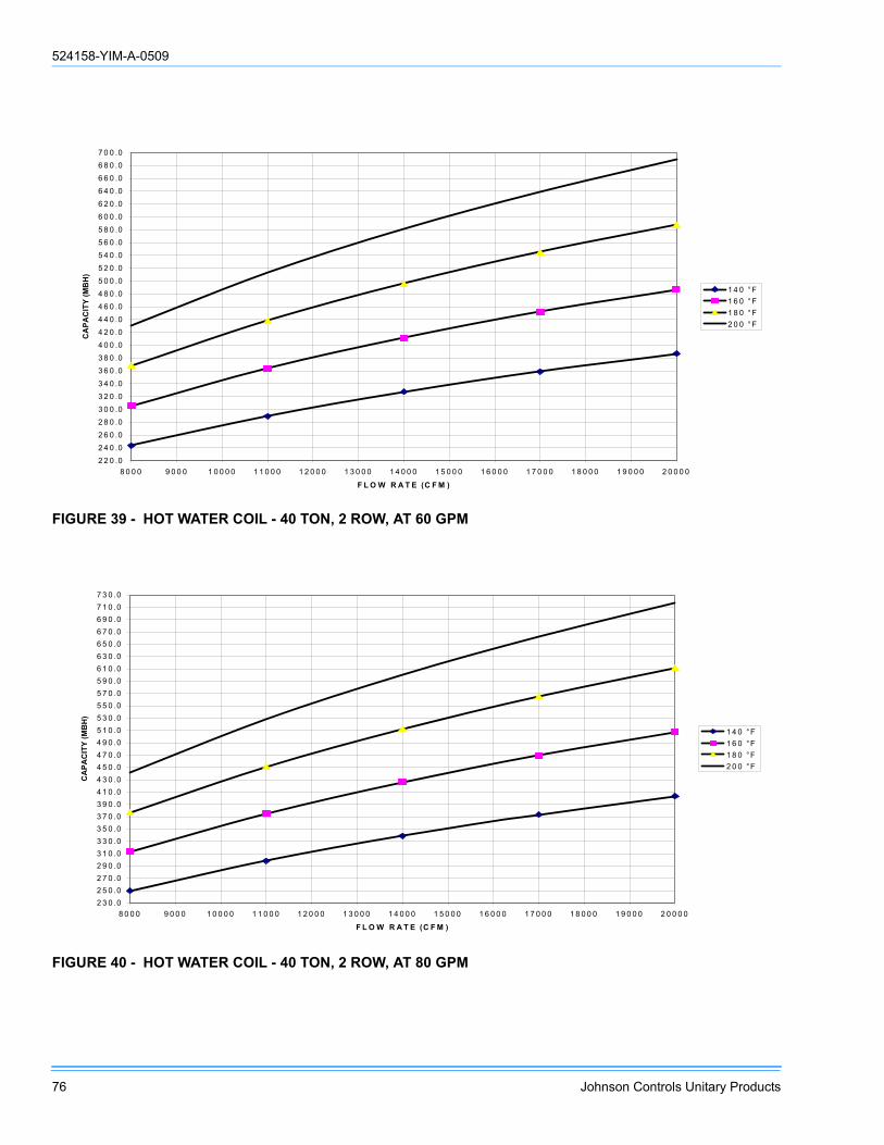
524158-YIM-A-0509
76 Johnson Controls Unitary Products
FIGURE 39 - HOT WATER COIL - 40 TON, 2 ROW, AT 60 GPM
2 2 0 .02 4 0 .02 6 0 .02 8 0 .03 0 0 .03 2 0 .03 4 0 .03 6 0 .03 8 0 .04 0 0 .04 2 0 .04 4 0 .04 6 0 .04 8 0 .05 0 0 .05 2 0 .05 4 0 .05 6 0 .05 8 0 .06 0 0 .06 2 0 .06 4 0 .06 6 0 .06 8 0 .07 0 0 .0
8 0 0 0 9 0 0 0 1 0 0 0 0 1 1 0 0 0 1 2 0 0 0 1 3 0 0 0 1 4 0 0 0 1 5 0 0 0 1 6 0 0 0 1 7 0 0 0 1 8 0 0 0 1 9 0 0 0 2 0 0 0 0
F L O W R A T E (C F M )
CA
PAC
ITY
(MB
H)
1 4 0 °F1 6 0 °F1 8 0 °F2 0 0 °F
FIGURE 40 - HOT WATER COIL - 40 TON, 2 ROW, AT 80 GPM
2 3 0 .02 5 0 .02 7 0 .02 9 0 .03 1 0 .03 3 0 .03 5 0 .03 7 0 .03 9 0 .04 1 0 .04 3 0 .04 5 0 .04 7 0 .04 9 0 .05 1 0 .05 3 0 .05 5 0 .05 7 0 .05 9 0 .06 1 0 .06 3 0 .06 5 0 .06 7 0 .06 9 0 .07 1 0 .07 3 0 .0
8 0 0 0 9 0 0 0 1 0 0 0 0 1 1 0 0 0 1 2 0 0 0 1 3 0 0 0 1 4 0 0 0 1 5 0 0 0 1 6 0 0 0 1 7 0 0 0 1 8 0 0 0 1 9 0 0 0 2 0 0 0 0
F L O W R A T E (C F M )
CA
PAC
ITY
(MB
H)
1 4 0 °F1 6 0 °F1 8 0 °F2 0 0 °F
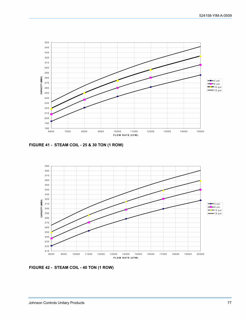
524158-YIM-A-0509
Johnson Controls Unitary Products 77
FIGURE 41 - STEAM COIL - 25 & 30 TON (1 ROW)
1 8 0
1 9 0
2 0 0
2 1 0
2 2 0
2 3 0
2 4 0
2 5 0
2 6 0
2 7 0
2 8 0
2 9 0
3 0 0
3 1 0
3 2 0
3 3 0
3 4 0
3 5 0
6 0 0 0 7 0 0 0 8 0 0 0 9 0 0 0 1 0 0 0 0 1 1 0 0 0 1 2 0 0 0 1 3 0 0 0 1 4 0 0 0 1 5 0 0 0
F L O W R A T E (C F M )
CA
PAC
ITY
(MB
H)
2 p s i6 p s i1 0 p s i1 5 p s i
FIGURE 42 - STEAM COIL - 40 TON (1 ROW)
2 1 0
2 2 0
2 3 0
2 4 0
2 5 0
2 6 0
2 7 0
2 8 0
2 9 0
3 0 0
3 1 0
3 2 0
3 3 0
3 4 0
3 5 0
3 6 0
3 7 0
3 8 0
3 9 0
8 0 0 0 9 0 0 0 1 0 0 0 0 1 1 0 0 0 1 2 0 0 0 1 3 0 0 0 1 4 0 0 0 1 5 0 0 0 1 6 0 0 0 1 7 0 0 0 1 8 0 0 0 1 9 0 0 0 2 0 0 0 0
F L O W R A T E (C F M )
CA
PAC
ITY
(MB
H)
2 p s i6 p s i1 0 p s i1 5 p s i
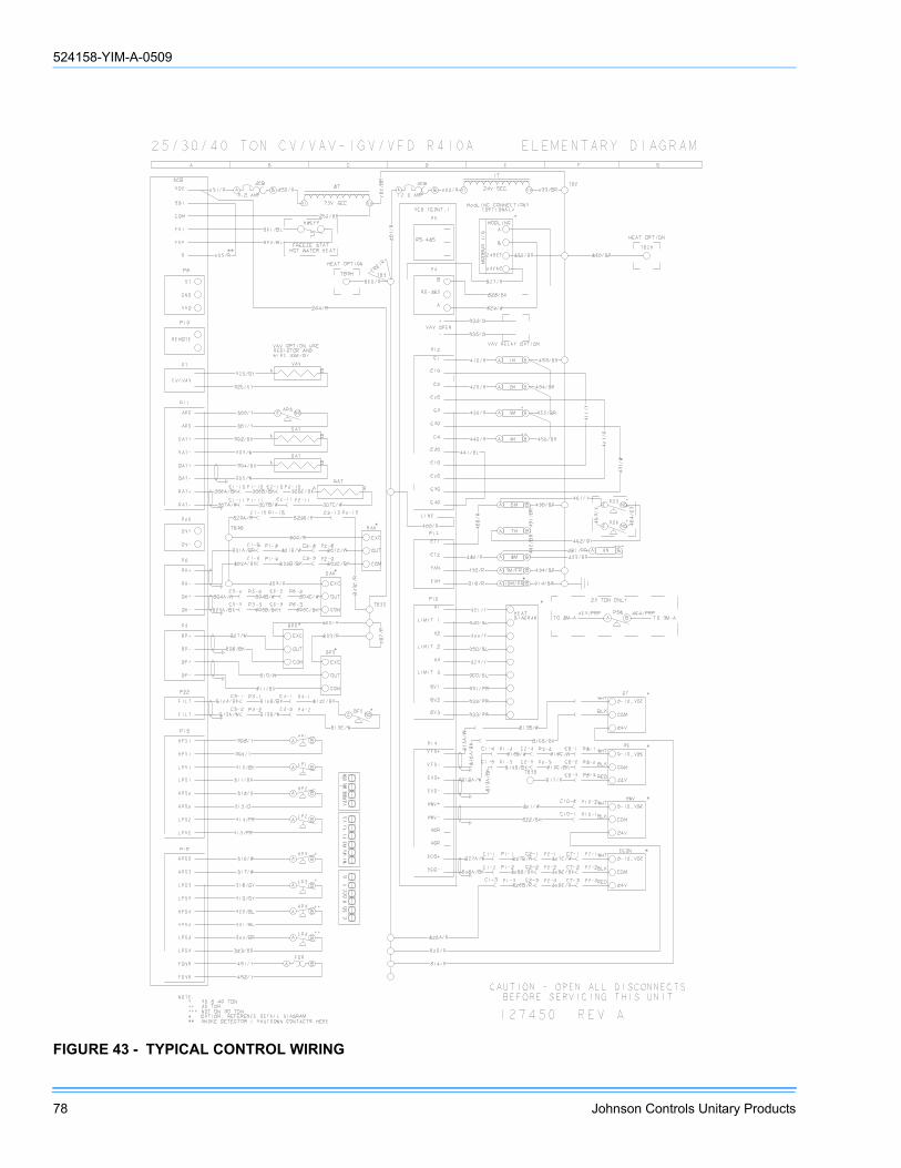
524158-YIM-A-0509
78 Johnson Controls Unitary Products
FIGURE 43 - TYPICAL CONTROL WIRING
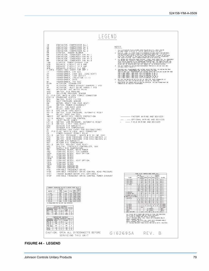
524158-YIM-A-0509
Johnson Controls Unitary Products 79
FIGURE 44 - LEGEND
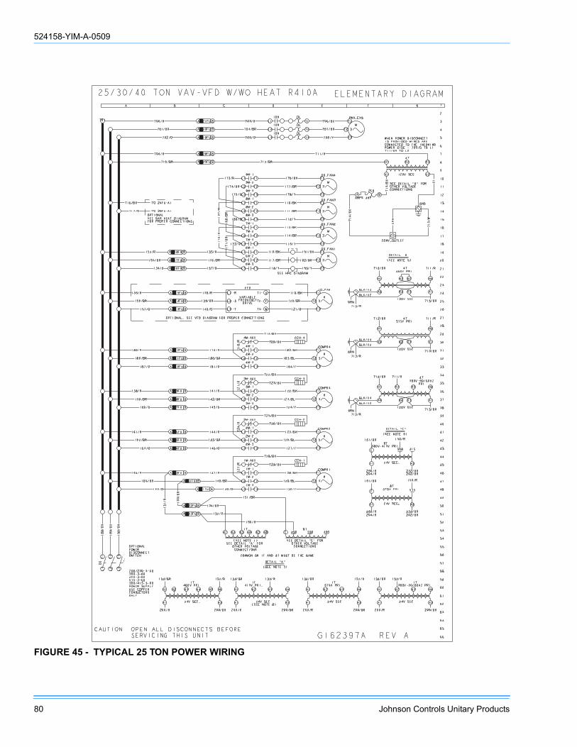
524158-YIM-A-0509
80 Johnson Controls Unitary Products
FIGURE 45 - TYPICAL 25 TON POWER WIRING

524158-YIM-A-0509
Johnson Controls Unitary Products 81
FIGURE 46 - TYPICAL STANDARD GAS HEAT WIRING
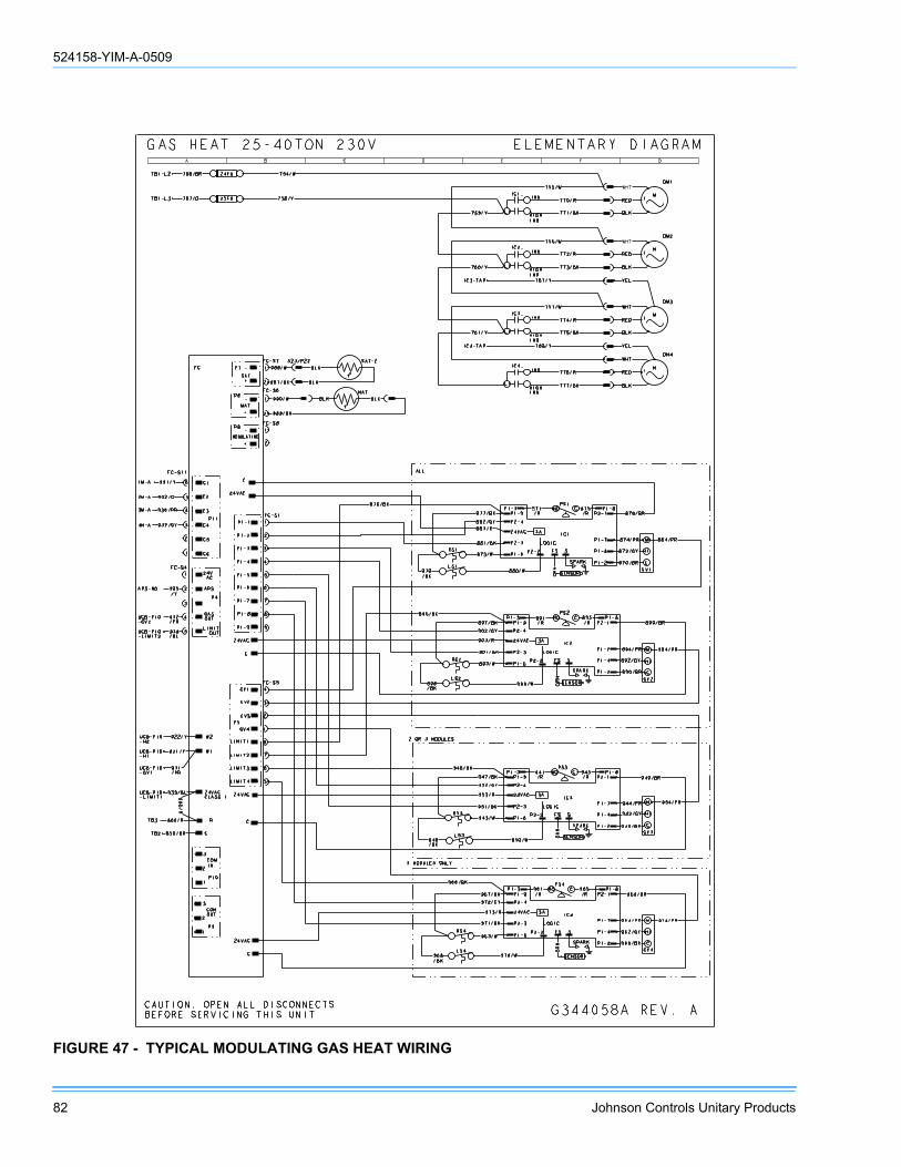
524158-YIM-A-0509
82 Johnson Controls Unitary Products
FIGURE 47 - TYPICAL MODULATING GAS HEAT WIRING
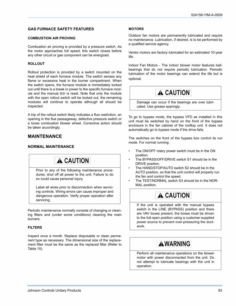
524158-YIM-A-0509
Johnson Controls Unitary Products 83
GAS FURNACE SAFETY FEATURES
COMBUSTION AIR PROVING
Combustion air proving is provided by a pressure switch. Asthe motor approaches full speed, this switch closes beforeany other circuit or gas component can be energized.
ROLLOUT
Rollout protection is provided by a switch mounted on theheat shield of each furnace module. The switch senses anyflame or excessive heat in the burner compartment. Whenthe switch opens, the furnace module is immediately lockedout until there is a break in power to the specific furnace mod-ule and the manual itch is reset. Note that only the modulewith the open rollout switch will be locked out, the remainingmodules will continue to operate although all should beinspected.
A trip of the rollout switch likely indicates a flue restriction, anopening in the flue passageway, defective pressure switch ora loose combustion blower wheel. Corrective action shouldbe taken accordingly.
MAINTENANCE
NORMAL MAINTENANCE
Periodic maintenance normally consists of changing or clean-ing filters and (under some conditions) cleaning the mainburners.
FILTERS
Inspect once a month. Replace disposable or clean perma-nent type as necessary. The dimensional size of the replace-ment filter must be the same as the replaced filter (Refer toTable 15).
MOTORS
Outdoor fan motors are permanently lubricated and requireno maintenance. Lubrication, if desired, is to be performed bya qualified service agency.
Ventor motors are factory lubricated for an estimated 10-yearlife.
Indoor Fan Motors - The indoor blower motor features ball-bearings that do not require periodic lubrication. Periodiclubrication of the motor bearings can extend the life but isoptional.
To go to bypass mode, the bypass VFD as installed in thisunit must be switched by hand on the front of the bypassenclosure in the fan cabinet of the rooftop unit. It does notautomatically go to bypass mode if the drive fails.
The switches on the front of the bypass box control its runmode. For normal running:
• The ON/OFF rotary power switch must be in the ON position.
• The BYPASS/OFF/DRIVE switch S1 should be in the DRIVE position.
• The HAND/STOP/AUTO switch S2 should be in the AUTO position, so that the unit control will properly run the fan and control the speed.
• The TEST/NORMAL switch S3 should be in the NOR-MAL position.
Prior to any of the following maintenance proce-dures, shut off all power to the unit. Failure to doso could cause personal injury.
Label all wires prior to disconnection when servic-ing controls. Wiring errors can cause improper anddangerous operation. Verify proper operation afterservicing.
Damage can occur if the bearings are over lubri-cated. Use grease sparingly.
If the unit is operated with the manual bypassswitch in the LINE (BYPASS) position and thereare VAV boxes present, the boxes must be drivento the full-open position using a customer-suppliedpower source to prevent over-pressuring the duct-work.
Perform all maintenance operations on the blowermotor with power disconnected from the unit. Donot attempt to lubricate bearings with the unit inoperation.

524158-YIM-A-0509
84 Johnson Controls Unitary Products
On an annual basis, check the motor for accumulations ofdust, etc. That may block the cooling slots in the motor shell.Check for loose, damaged or misaligned drive components.Check that all mounting bolts are tight. Replace defectiveparts as required.
If desired, every three years remove both pipe plugs at eachend shell and clean out any hardened grease or foreign mat-ter. Replace one plug on each end with a clean grease fitting.Using a low pressure grease gun, pump grease (ChevronSRI-2 or equivalent) into the bearing cavity until new greaseshows at the open port. Do not over-lubricate. Run the motorfor ten minutes until excess grease is purged from the cavity.Replace the plugs.
FAN DRIVES
Units are supplied with fan shaft bearings that do not requiremaintenance but may be relubricated per Table 59.
Lubricate with a premium quality NLGI 2 grade multi-purposeroller bearing grease having corrosion inhibitors, anti-oxidantadditives and mechanical stability for high speed operation.The grease should also have a minimum base oil viscosity of500 SUS at 100°F. Do not use a heavy, long fibered grease.
The presents of dirt, moisture or chemical fumes around thebearings requires more frequent lubrication.
Fill bearings with lubricant prior to extended shutdown or stor-age. Rotate the shaft monthly during idle periods.
Avoid excessive grease purging from seals during lubrication,this reduces the life of the bearing.
OUTDOOR COIL
Dirt should not be allowed to accumulate on the outdoor coilsurface or other parts in the air circuit. Cleaning should be asoften as necessary to keep coil clean. Use a brush, vacuumcleaner attachment, or other suitable means. If water is usedto clean coil, be sure power to the unit is shut off prior tocleaning.
NOTE: Exercise care when cleaning the coil so that the coilfins are not damaged.
Do not permit the hot condenser air discharge to beobstructed by overhanging structures or shrubs.
GAS BURNER
Periodically (at least annually at the beginning of each heat-ing season) make a visual check of the main burner flame. Ifnecessary, adjust main burner primary air shutters to give adistinct, sharp blue flame as explained under BURNERINSTRUCTIONS.
TO CLEAN BURNERS
Remove them from the furnace as explained in BURNERINSTRUCTIONS. Clean burners with hot water applied alongtop of the burner.
COMBUSTION AIR DISCHARGE
Visually inspect discharge outlet periodically to make surethat the buildup of soot and dirt is not excessive. If necessary,clean to maintain adequate combustion air discharge.
CLEANING FLUE PASSAGES AND HEATING ELEMENTS
With proper combustion adjustment, the heating element of agas fired furnace will seldom need cleaning. If the elementshould become sooted, it can be cleaned as follows:
1. Remove the burner assembly as outlined in BURNER INSTRUCTIONS.
2. Remove the screws holding the top of the flue collector box. Carefully remove the top of the flue collector box. The draft wheel, housing, and draft motor can remain assembled to the flue box top, if cleaning of these com-ponents is not required.
3. This will provide access to flue baffles, then remove the flue baffles from the tube interiors. To remove, the flue baffles, remove the stainless steel screws from the vest panel. Refer to Figure 48.
4. Using a wire brush on a flexible wand, brush out the inside of each heat exchanger from the burner inlet and flue outlet ends.
5. Brush out the inside of the flue collector box, and the flue baffles.
6. Run the wire brush down the vent hoods from the flue collector end.
7. If soot build-up is particularly bad, remove the vent motor and clean the wheels and housings. Run the wire brush down the flue extension at the outlet of the vent hous-ings.
8. After brushing is complete, blow all brushed areas with air or nitrogen. Vacuum as needed.
TABLE 59: INDOOR BLOWER BEARING LUBRICATION SCHEDULE
Shaft Size (Inches)
Operating Speed (RPM)
500 1000 1500 2000
Relubrication Cycle (Months)
1-1/16 - 1-7/16 6 6 6 6
1-1/2 - 1-3/4 6 6 6 4
1-7/8 - 2-3/16 6 6 4 4
2 -1/4 - 3 6 4 4 2
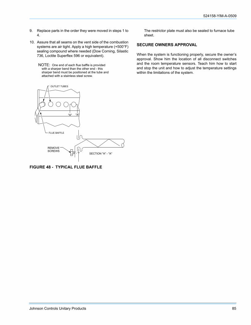
524158-YIM-A-0509
Johnson Controls Unitary Products 85
9. Replace parts in the order they were moved in steps 1 to 4.
10. Assure that all seams on the vent side of the combustion systems are air tight. Apply a high temperature (+500°F) sealing compound where needed (Dow Corning, Silastic 736, Loctite Superflex 596 or equivalent).
The restrictor plate must also be sealed to furnace tube sheet.
SECURE OWNERS APPROVAL
When the system is functioning properly, secure the owner’sapproval. Show him the location of all disconnect switchesand the room temperature sensors. Teach him how to startand stop the unit and how to adjust the temperature settingswithin the limitations of the system.
FIGURE 48 - TYPICAL FLUE BAFFLE
��� ���
����������
���������
�������������������������������������� ������������� ��� ��� ������! ��������������"�� ������ ������ �� ������� ������� ��� �������� ��������#
$�%�&��'$�(�
��'�)� ���!���

524158-YIM-A-0509
86 Johnson Controls Unitary Products
FIGURE 49 - 25 TON CHARGING CURVE
25 TON CHARGING CURVE
200
250
300
350
400
450
500
550
75 100 125 150 175SUCTION PRESSURE (PSIG)
DIS
CH
AR
GE
PRES
SUR
E (P
SIG
)
65 F
75 F
85 F
95 F
105 F
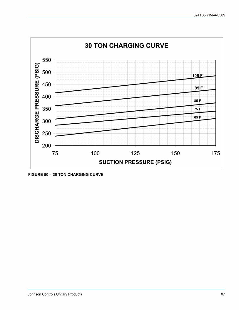
524158-YIM-A-0509
Johnson Controls Unitary Products 87
FIGURE 50 - 30 TON CHARGING CURVE
30 TON CHARGING CURVE
200
250
300
350
400
450
500
550
75 100 125 150 175SUCTION PRESSURE (PSIG)
DIS
CH
AR
GE
PRES
SUR
E (P
SIG
)
105 F
95 F
85 F
75 F
65 F
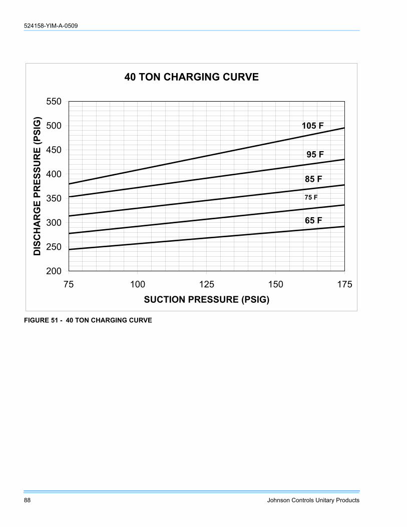
524158-YIM-A-0509
88 Johnson Controls Unitary Products
FIGURE 51 - 40 TON CHARGING CURVE
40 TON CHARGING CURVE
200
250
300
350
400
450
500
550
75 100 125 150 175SUCTION PRESSURE (PSIG)
DIS
CH
AR
GE
PRES
SUR
E (P
SIG
)
105 F
95 F
85 F
75 F
65 F

524158-YIM-A-0509
Johnson Controls Unitary Products 89
FIGURE 52 - PRESSURE DROP DRY EVAPORATOR COIL VS SUPPLY AIR CFM - 25 TON
PRESSURE DROP ACROSS A DRY EVAPORATOR COIL 25T
0
0.1
0.2
0.3
0.4
0.5
0.6
0 1 2 3 4 5 6 7 8 9 10 11 12 13NOMINAL CFM (THOUSANDS)
PRES
SUR
E D
RO
P (in
. wg.
)
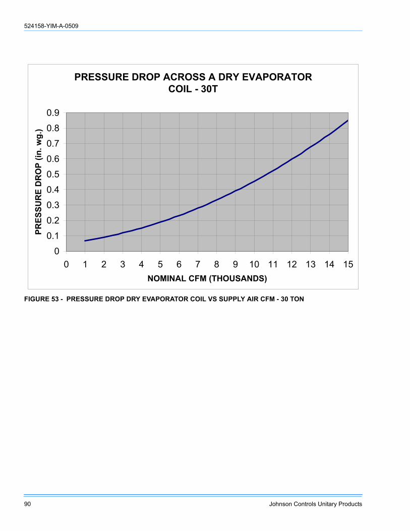
524158-YIM-A-0509
90 Johnson Controls Unitary Products
FIGURE 53 - PRESSURE DROP DRY EVAPORATOR COIL VS SUPPLY AIR CFM - 30 TON
PRESSURE DROP ACROSS A DRY EVAPORATOR COIL - 30T
0
0.1
0.2
0.3
0.4
0.5
0.6
0.7
0.8
0.9
0 1 2 3 4 5 6 7 8 9 10 11 12 13 14 15NOMINAL CFM (THOUSANDS)
PRES
SUR
E D
RO
P (in
. wg.
)

524158-YIM-A-0509
Johnson Controls Unitary Products 91
FIGURE 54 - PRESSURE DROP DRY EVAPORATOR COIL VS SUPPLY AIR CFM - 40 TON
LIOC ROTAROPAVE YRD A SSORCA PORD ERUSSERPT04
01.02.03.04.05.06.07.08.09.0
8171615141312111019876543210)SDNASUOHT( MFC LANIMON
PRES
SUR
E D
RO
P (in
. wg.
)
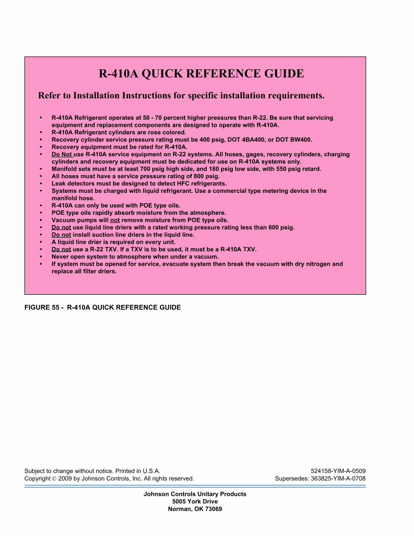
Subject to change without notice. Printed in U.S.A. 524158-YIM-A-0509Copyright © 2009 by Johnson Controls, Inc. All rights reserved. Supersedes: 363825-YIM-A-0708
Johnson Controls Unitary Products5005 York Drive
Norman, OK 73069
FIGURE 55 - R-410A QUICK REFERENCE GUIDE
R-410A QUICK REFERENCE GUIDE
Refer to Installation Instructions for specific installation requirements.
R-410A Refrigerant operates at 50 - 70 percent higher pressures than R-22. Be sure that servicingequipment and replacement components are designed to operate with R-410A.R-410A Refrigerant cylinders are rose colored.Recovery cylinder service pressure rating must be 400 psig, DOT 4BA400, or DOT BW400.Recovery equipment must be rated for R-410A.Do Not use R-410A service equipment on R-22 systems. All hoses, gages, recovery cylinders, chargingcylinders and recovery equipment must be dedicated for use on R-410A systems only.Manifold sets must be at least 700 psig high side, and 180 psig low side, with 550 psig retard.All hoses must have a service pressure rating of 800 psig.Leak detectors must be designed to detect HFC refrigerants.Systems must be charged with liquid refrigerant. Use a commercial type metering device in themanifold hose.R-410A can only be used with POE type oils.POE type oils rapidly absorb moisture from the atmosphere.Vacuum pumps will not remove moisture from POE type oils.Do not use liquid line driers with a rated working pressure rating less than 600 psig.Do not install suction line driers in the liquid line.A liquid line drier is required on every unit.Do not use a R-22 TXV. If a TXV is to be used, it must be a R-410A TXV.Never open system to atmosphere when under a vacuum.If system must be opened for service, evacuate system then break the vacuum with dry nitrogen andreplace all filter driers.