installation of fee guard tank vent line and leak check ... · helium leak check ... this procedure...
TRANSCRIPT

Stanford University Gravity Probe B Program
P0916 Rev -
GRAVITY PROBE B
PROCEDURE FOR
SCIENCE MISSION DEWAR
INSTALLATION OF
FEE GUARD TANK VENT LINE
AND LEAK CHECK WITH SV VERTICAL
P0916 Rev-
May 16, 2002
Prepared by: Checked by:
______________________Date_______ ______________________Date_______
Dave Murray Mike Taber
Cryogenic Test Payload Test Director
Approvals:
______________________Date_______ ______________________Date_______
Dorrene Ross Robert Brumley
Quality Assurance Payload Technical Manager
______________________Date_______
Harv Moskowitz
Payload Safety

Installation of FEE Guard Tank Vent Line Gravity Probe-B Program
and Leak Check with SV Vertical P0916 Rev-
P0916.doc 6/3/2002 9:07:00 AM ii
REVISION RECORD
REVISION ECO PAGES
DATE
Original - All May 16, 2002

Installation of FEE Guard Tank Vent Line Gravity Probe-B Program
and Leak Check with SV Vertical P0916 Rev-
P0916.doc 6/3/2002 9:07:00 AM iii
TABLE OF CONTENTS
A. SCOPE............................................................................................................................... 1
B. SAFETY.............................................................................................................................. 1
B.1. Potential Hazards..................................................................................................................... 1
B.2. Mitigation of Hazards................................................................................................................ 1
B.3. Mishap Notification................................................................................................................... 1
C. QUALITY ASSURANCE ..................................................................................................... 2
C.1. QA Notification ......................................................................................................................... 2
C.2. Red-line Authority..................................................................................................................... 2
C.3. Discrepancies .......................................................................................................................... 2
D. TEST PERSONNEL ........................................................................................................... 3
D.1. Personnel Responsibilities........................................................................................................ 3
D.2. Personnel Qualifications........................................................................................................... 3
D.3. Qualified Personnel .................................................................................................................. 3
E. REQUIREMENTS............................................................................................................... 3
E.1. Electrostatic Discharge Requirements ...................................................................................... 3
E.2. Lifting Operation Requirements ................................................................................................ 3
E.3. Hardware/Software Requirements............................................................................................ 3
E.4. Instrument Pretest Requirements ............................................................................................. 6
E.5. Configuration Requirements ..................................................................................................... 7
E.6. Optional Non-flight Configurations ............................................................................................ 9
E.7. Verification/ Success Criteria.................................................................................................... 9
E.8. Payload Constraints and Restrictions ....................................................................................... 9
F. REFERENCE DOCUMENTS............................................................................................ 10
F.1. Drawings................................................................................................................................ 10
F.2. Supporting documentation...................................................................................................... 10
F.3. Additional Procedures ............................................................................................................ 10
G. OPERATIONS .................................................................................................................. 11
G.1. Perform Preparatory Operations............................................................................................. 11
G.2. Connect GTV to GM............................................................................................................... 12
G.3. Verify Configuration Requirements ......................................................................................... 13
Installation of FEE Guard Tank Vent Line Gravity Probe-B Program
and Leak Check with SV Vertical P0916 Rev-
P0916.doc 6/3/2002 9:07:00 AM iv
G.4. Verify Gas-Module Configuration and Record Initial Conditions............................................... 15
G.5. Set Up Data Acquisition System ............................................................................................. 16
G.6. Prepare FEE Guard Tank Vent Line (FGTVL)......................................................................... 17
G.7. Remove GT Short Vent Line................................................................................................... 18
G.8. Install FGTVL ......................................................................................................................... 20
G.9. Preparing Equipment for Leak Detection................................................................................. 21
G.10. Remove Liquid Helium from Guard Tank............................................................................. 22
G.11. Pump Guard Tank with AP-1............................................................................................... 22
G.12. Configure for Neon Leak Detection ..................................................................................... 24
G.13. Leak Check at 50 Torr ........................................................................................................ 25
G.14. Pumping Guard Tank to Vacuum and Leak Check .............................................................. 26
G.15. Leak Check at low pressure ................................................................................................ 27
G.16. Helium Leak Check............................................................................................................. 29
G.17. Re-pressurize Guard Tank with Helium Gas from Main Tank............................................... 31
G.18. Prepare Fill Line.................................................................................................................. 31
G.19. Open RAV-1 ....................................................................................................................... 32
G.20. Open RAV-2 ....................................................................................................................... 32
G.21. Close RAV-2....................................................................................................................... 33
G.22. Close RAV-1 and Pump Fill Line......................................................................................... 33
G.23. Pump Fill Line..................................................................................................................... 35
G.24. Final Configuration.............................................................................................................. 36
G.25. Configuration of Dewar and GSE ........................................................................................ 36
G.26. Setting up Data Acquisition ................................................................................................. 36
H. PROCEDURE COMPLETION .......................................................................................... 37
I. APPENDICES................................................................................................................... 44
I.1. Appendix 1 Pre-Test Check List............................................................................................. 44
I.2. Appendix 2 Post-Test Check List ........................................................................................... 45
I.3. Appendix 3– Contingency Responses .................................................................................... 46

Installation of FEE Guard Tank Vent Line Gravity Probe-B Program
and Leak Check with SV Vertical P0916 Rev-
P0916.doc 6/3/2002 9:07:00 AM v
LIST OF ABBREVIATIONS AND ACRONYMS
AG-x Gauge x of Gas Module auxiliary section LM Lockheed Martin Co.
AMI American Magnetics Inc. MT Main Tank
ATC Advanced Technology Center MTVC Main Tank Vent Cap
APR-x Pressure regulator x of Gas Module MTVC-G Main Tank Vent Cap pressure gauge
AV-x Valve x of Gas Module auxiliary section MTVC-RV Main Tank Vent Cap relief valve
CG-x Gauge x of portable helium pressurization source MTVC-V Main Tank Vent Cap valve
CPR-x Pressure regulator x of portable helium pressurization NBP Normal boiling point
CV-x Valve x of portable helium pressurization source ONR Office of Naval Research
CN [xx] Data acquisition channel number FCG Fill Cap assembly pressure Gauge
DAS Data Acquisition System PFM Pump equipment Flow Meter
EFM Exhaust gas Flow Meter PG-x Gauge x of Pump equipment
EG-x Gauge x of Gas Module exhaust section PM Pump Module
EH-x Vent line heat exchanger in Gas Module Psi pounds per square inch
EM Electrical Module Psig pounds per square inch gauge
ERV-x Relief valve of Gas Module exhaust section
EV-x Valve number x of Gas Module exhaust section PV-x Valve x of the Pump equipment
FCV Fill Cap Valve QA Quality Assurance
FEE Forward Equipment Enclosure RAV-x Remote Actuated Valve-x
FIST Full Integrated System Test
FGTVL FEE Guard Tank Vent Line RGA Residual Gas Analyzer
GHe Gaseous Helium SMD Science Mission Dewar
GM Gas Module STV SMD Thruster vent Valve
GP-B Gravity Probe-B SU Stanford University
GSE Ground Support Equipment SV-x SMD Valve number x
GT Guard Tank TG-x Gauge x of Utility Turbo System
GTVC Guard Tank Vent Cap TV-x Valve x of Utility Turbo System
GTVC-G Guard Tank Vent Cap pressure gauge UTS Utility Turbo System
GTVC-RV Guard Tank Vent Cap relief valve Vac Vacuum
GTVC-V Guard Tank Vent Cap valve VCP-x Vent cap pressure gauge
GTV-G Guard Tank vent pressure gauge VCRV-x Vent cap relief valve
GTV-RV Guard Tank vent relief valve VCV-x Vent cap valve
GTV-V Guard Tank vent valve VDC Volts Direct Current
GTV-Va Guard Tank Vent auxiliary valve
KFxx Quick connect o-ring vacuum flange (xx mm diameter)
VF-x Liquid helium Fill line valve
LHe Liquid Helium VG-x Gauge x of Vacuum Module
LHSD Liquid Helium Supply Dewar VM Vacuum Module
LHV-x Liquid Helium Supply Dewar valves VV-x Valve x of Vacuum Module
LLS Liquid level sensor VW-x Valve x of Dewar Adapter

Installation of FEE Guard Tank Vent Line Gravity Probe-B Program
and Leak Check with SV Vertical P0916 Rev-
P0916.doc 6/3/2002 9:07:00 AM 1
A. Scope
This procedure describes the steps to effect the removal and replacement of the Guard Tank Short Vent Line with the FEE Guard Tank Vent Line. This process assumes liquid helium in the Guard Tank and the SV in a vertical orientation. The steps for installing the FEE Guard Tank Vent Line are given in a LM Operations Order No. INT-251 and will be carried out by LM personnel.
B. Safety
B.1. Potential Hazards
Liquid helium used in the SMD represents a hazardous material for the personnel involved in the operations. Cryogenic burns can be caused by contact with the cold liquid or gas, high pressures can result if boiling liquid or cold gas is confined without a vent path, and asphyxiation can result if the vent gas is allowed to accumulate.
The SMD Safety Compliance Assessment, document GPB-100153C discusses the safety design, operating requirements and the hazard analysis of the SMD.
B.2. Mitigation of Hazards
B.2.1. Lifting hazards
There are no lifting operations in this procedure
B.2.2. Cryogenic Hazards
Temperature and pressure alarms, provided by the DAS, warn of potential over-pressure conditions. Emergency vent line deflectors are installed over the four burst disks on the SMD vacuum shell.
Only authorized and trained LM and SU personnel are allowed in proximity to the SV without escort. All personnel working at a height 30 inches or more off the floor are required to have a LM approved air tank within easy reach. In the unlikely event of a large LHe spill all employees have been instructed to evacuate the room and contact LM safety.
The following additional requirements apply to all personnel involved directly in cryogenic operations. Gloves that are impervious to liquid helium and liquid nitrogen are to be worn whenever the possibility of splashing or impingement of high-velocity cryogens exists or when handling equipment that has been cooled to cryogenic temperatures. Protective clothing and full-face shields are to be worn whenever the possibility of splashing cryogens exists.
B.2.3. Other Hazards
When appropriate, tools or other items used with the potential to damage the SMD or Probe shall be tethered.
B.3. Mishap Notification

Installation of FEE Guard Tank Vent Line Gravity Probe-B Program
and Leak Check with SV Vertical P0916 Rev-
P0916.doc 6/3/2002 9:07:00 AM 2
B.3.1. Injury
In case of any injury obtain medical treatment by immediately calling 117
B.3.2. Hardware Mishap
In case of an accident, incident, or mishap, notification is to proceed per the procedures outlined SU P0879 and as referenced therein to Lockheed Martin Engineering Memorandum EM SYS229.
B.3.3. Contingency Response
Contingency responses to possible equipment troubles or irregularities (e.g., power failure) are listed in Appendix 3.
C. Quality Assurance
C.1. QA Notification
The NASA representative and SU QA shall be notified 24 hours prior to the start of this procedure. Upon completion of this procedure, QA will certify his/her concurrence that the effort was performed and accomplished in accordance with the prescribed instructions by signing and dating in the designated place(s) in this document.
C.2. Red-line Authority
Authority to red-line (make minor changes during execution) this procedure is given solely to the Test Director or his designate and shall be approved by the QA Representative. Additionally, approval by the Payload Technical Manager shall be required, if in the judgment of the test director or QA Representative, experiment functionality may be affected.
C.3. Discrepancies
A Quality Assurance Representative designated by D. Ross shall review any discrepancy noted during this procedure, and approve its disposition. Discrepancies will be recorded in a D-log or a DR per Quality Plan P0108. Any time a procedure calls for verification of a specific configuration and that configuration is not the current configuration; it represents a discrepancy of one of three types. These types are to be dealt with as described below.
C.3.1. If the discrepancy has minimal effect on procedure functionality (such as the state of a valve that is irrelevant to performance of the procedure) it shall be documented in the procedure, together with the resolution. Redlines to procedures are included in this category.
C.3.2. If the discrepancy is minor and affects procedure functionality but not flight hardware fit or function, it shall be recorded in the D-log. Resolution shall be in consultation with the Test Director and approved by the QA representative.
C.3.3. All critical and major discrepancies, those that effect flight hardware fit

Installation of FEE Guard Tank Vent Line Gravity Probe-B Program
and Leak Check with SV Vertical P0916 Rev-
P0916.doc 6/3/2002 9:07:00 AM 3
or functions, shall be documented in a D-log and also in a Discrepancy Report, per P0108.
D. Test Personnel
D.1. Personnel Responsibilities
The performance of this procedure requires a minimum complement of personnel as determined by the Test Director. However, during the startup of the transfer (Sec. G.14), there are to be a minimum of two qualified persons (Sec. D.3) in attendance. The person performing the operations (Test Director or Test Engineer) is to sign the “Completed by” sign-off. Any other qualified person or QA person who can attest to the successful performance of this procedure may sign the “Witnessed by” sign-off. The Test Director will perform pre-test and Post-Test briefings in accordance with P0875 “GP-B Maintenance and Testing at all Facilities”. Checklists will be used as directed by P0875.
D.2. Personnel Qualifications
The Test Director must have a detailed understanding of all procedures and facility operations and experience in all of the SMD operations. Test Engineers must have SMD Cryogenic operations experience and an understanding of the operations and procedures used for the cryogenic servicing/maintenance of the Dewar.
D.3. Qualified Personnel
The names of those actually performing this procedure are to be initialed and the name of the person acting as Test Director should be circled.
Test Director Test Engineer
Mike Taber
Dave Murray
Tom Welsh
Ned Calder
E. Requirements
E.1. Electrostatic Discharge Requirements
All work on the SV requires the use of grounding wrist straps attached to grounding points on the SV per LM requirement.
E.2. Lifting Operation Requirements
There are no lifting operations in this procedure
E.3. Hardware/Software Requirements
E.3.1. Commercial Test Equipment
Leak Detector
E.3.2. Ground Support Equipment
Installation of FEE Guard Tank Vent Line Gravity Probe-B Program
and Leak Check with SV Vertical P0916 Rev-
P0916.doc 6/3/2002 9:07:00 AM 4
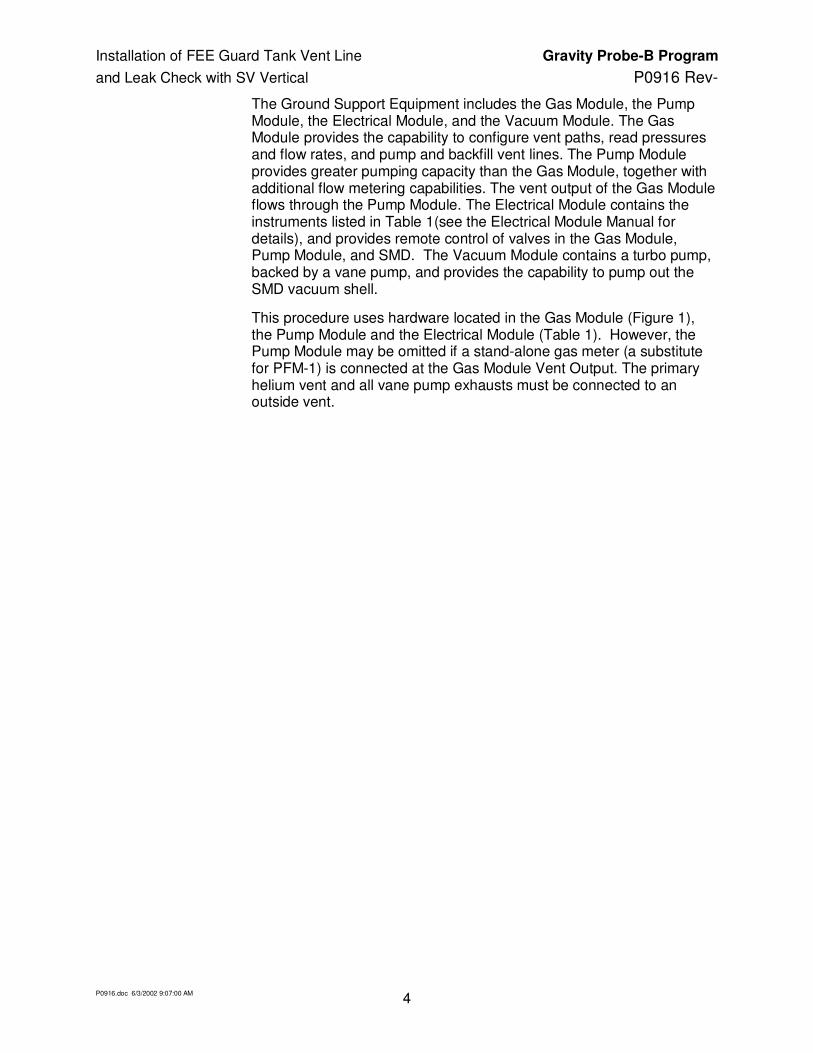
The Ground Support Equipment includes the Gas Module, the Pump Module, the Electrical Module, and the Vacuum Module. The Gas Module provides the capability to configure vent paths, read pressures and flow rates, and pump and backfill vent lines. The Pump Module provides greater pumping capacity than the Gas Module, together with additional flow metering capabilities. The vent output of the Gas Module flows through the Pump Module. The Electrical Module contains the instruments listed in Table 1(see the Electrical Module Manual for details), and provides remote control of valves in the Gas Module, Pump Module, and SMD. The Vacuum Module contains a turbo pump, backed by a vane pump, and provides the capability to pump out the SMD vacuum shell.
This procedure uses hardware located in the Gas Module (Figure 1), the Pump Module and the Electrical Module (Table 1). However, the Pump Module may be omitted if a stand-alone gas meter (a substitute for PFM-1) is connected at the Gas Module Vent Output. The primary helium vent and all vane pump exhausts must be connected to an outside vent.

Installation of FEE Guard Tank Vent Line Gravity Probe-B Program
and Leak Check with SV Vertical P0916 Rev-
P0916.doc 6/3/2002 9:07:00 AM 5
E.3.3. Computers and Software:
The Data Acquisition System (DAS) and data acquisition software are required for this procedure. The DAS reads and displays pressures, temperatures, and flow rates and monitors critical parameters. No additional computers or software are required.
E.3.4. Additional Test Equipment
Description Manufacturer Model
AMI Level Sensor Readout for LHSD AMI 110
E.3.5. Additional Hardware
Description Manufacturer Model
SMD Vent Bayonet O-rings Parker 2-027
SMD Bayonet fit check tool SU N/A
Apiezon MI Products Ltd Model N
No. 5 rubber stopper with .5 psid relief valve
N/A N/A
E.3.6. Tools
Description Serial No. Cal Due
Strap wrench 2-in. N/A N/A
E.3.7. Expendables
Description Quantity Mfr./Part No.
Ethyl alcohol AR N/A
99.99% pure gaseous helium AR N/A
Tie wraps – large size AR N/A

Installation of FEE Guard Tank Vent Line Gravity Probe-B Program
and Leak Check with SV Vertical P0916 Rev-
P0916.doc 6/3/2002 9:07:00 AM 6
E.4. Instrument Pretest Requirements
The GSE instruments required to perform this procedure are listed in Table 1, together with their serial numbers, where available. Instruments that are required to have current calibrations are indicated in the Cal-Required column. Instruments that do not require calibration are those not used to verify performance requirements and are not connected to flight instrumentation. The status column is to be filled in with the due date of the instrument calibration sticker and verified to be in calibration by QE or QE designee. Serial numbers are to be updated as appropriate.
Table 1. Required Instrumentation and Calibration Status
No.
Location
Description
User Name
Serial No.
Cal Required
Status Cal due date
1 DAS Power Supply, H-P 6627A A1, A2, A3, A4 3452A01975 Yes
2 DAS Power Supply, H-P 6627A B1, B2, B3, B4 3452A01956 Yes
3 DAS Data Acquisition/Control Unit H-P 3497A
- 2936A245539 No -
4 DAS Digital Multimeter H-P 3458A
- 2823A15047 Yes
5 EM Vacuum Gauge Controller Granville-Phillips Model 316
EG-1a, -1b 2827 No -
6 EM Vacuum Gauge Controller Granville-Phillips Model 316
AG-2a, -2b 2826 No -
7 EM Vacuum Gauge Controller Granville-Phillips Model 316
EG-3 2828 No -
8 EM MKS PDR-C-2C EG-2, FCG 92022108A No -
9 EM Flow meter – Matheson 8170 EFM-1 96186 No -
10 EM Flow meter totalizer Matheson 8124
EFM-1 96174 No -
11 EM Liquid Helium Level Controller American Magnetics, Inc. 136
LLS Main Tank 96-409-11 No -
12 EM Liquid Helium Level Controller American Magnetics, Inc. 136
LLS Guard Tank 96-409-10 No -
13 EM Liquid Helium Level Controller American Magnetics, Inc. 136
LLS Well 96-409-9 No -
14 EM Liquid Helium Level Controller American Magnetics, Inc. 136
LLS Axial Lock 96-409-12 No -
15 EM Pressure Controller – MKS 152F-92 EV-7a, -7b 96203410A No -
16 EM Power Supply HP 6038A
H08D Tank Heater
96023407A Yes

Installation of FEE Guard Tank Vent Line Gravity Probe-B Program
and Leak Check with SV Vertical P0916 Rev-
P0916.doc 6/3/2002 9:07:00 AM 7
No.
Location
Description
User Name
Serial No.
Cal Required
Status Cal due date
17 EM Power Supply HP 6038A
H09D Tank Heater
3511A-13332 Yes
18 EM Power Supply HP 6038A
RAV Power Supply
3329A-12486 Yes
19 EM Vac Ion Pump power supply Varian 929-0910, Minivac
SIP 5004N No
-
20 EM Flow meter totalizer Veeder-Root
PFM-1 576013-716 No -
21 GM Pressure Gauge, Heise AG-1 CC-122077 No -
22 GM Pressure Gauge, Marshall Town AG-3 N/A No -
23 GM Main Tank Heat Exchanger: a) Thermocouple, b) Current meter, c) Temperature set point controller
EH-1 C-19950 No -
24 GM Guard Tank Heat Exchanger: a) Thermocouple, b) Current meter, c) Temperature set point controller
EH-2 C-09920 No -
25 VM Vacuum Gauge readout, Granville-Phillips 316
VG-3 VG-4
2878 No -
26 VM Vacuum Gauge readout, Granville-Phillips 360
VG-1, VG-2 VG-5
96021521 No -
27 Leak Detector
Standard leak internal to leak detector N/A - N/A Yes
E.5. Configuration Requirements
E.5.1. Main Tank
Liquid in the Main Tank must be at its normal boiling point (NBP), 4.2 K. The SMD is vertical with the +Z axis up. The actuator control valve for EV-9 controls the state to which EV-9 defaults should a power failure occur. For this procedure it must be in the “NBP.” Position, ensuring that EV-9 remains open in the event of power failure.
E.5.2. Guard Tank
The Guard Tank is filled with liquid helium to a level greater than 20%.
Installation of FEE Guard Tank Vent Line Gravity Probe-B Program
and Leak Check with SV Vertical P0916 Rev-
P0916.doc 6/3/2002 9:07:00 AM 8
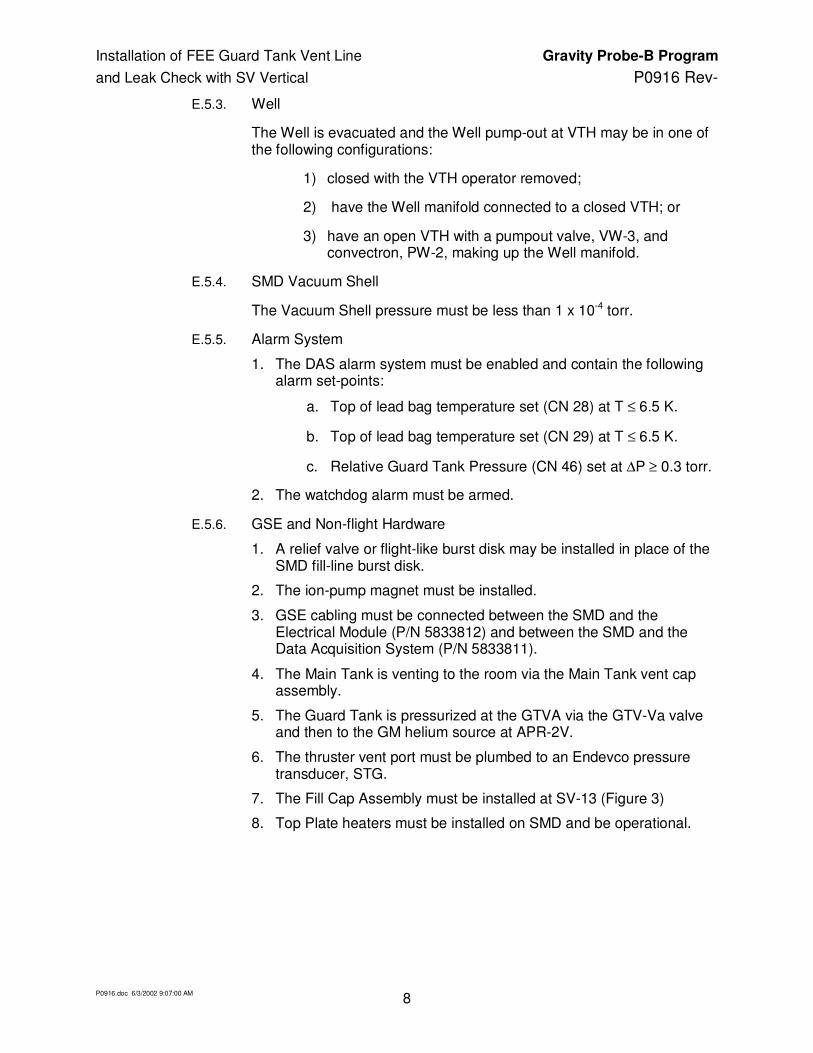
E.5.3. Well
The Well is evacuated and the Well pump-out at VTH may be in one of the following configurations:
1) closed with the VTH operator removed;
2) have the Well manifold connected to a closed VTH; or
3) have an open VTH with a pumpout valve, VW-3, and convectron, PW-2, making up the Well manifold.
E.5.4. SMD Vacuum Shell
The Vacuum Shell pressure must be less than 1 x 10⁻⁴ torr.
E.5.5. Alarm System
1. The DAS alarm system must be enabled and contain the following alarm set-points:
a. Top of lead bag temperature set (CN 28) at T ≤ 6.5 K.
b. Top of lead bag temperature set (CN 29) at T ≤ 6.5 K.
c. Relative Guard Tank Pressure (CN 46) set at ∆P ≥ 0.3 torr.
2. The watchdog alarm must be armed.
E.5.6. GSE and Non-flight Hardware
1. A relief valve or flight-like burst disk may be installed in place of the SMD fill-line burst disk.
2. The ion-pump magnet must be installed.
3. GSE cabling must be connected between the SMD and the Electrical Module (P/N 5833812) and between the SMD and the Data Acquisition System (P/N 5833811).
4. The Main Tank is venting to the room via the Main Tank vent cap assembly.
5. The Guard Tank is pressurized at the GTVA via the GTV-Va valve and then to the GM helium source at APR-2V.
6. The thruster vent port must be plumbed to an Endevco pressure transducer, STG.
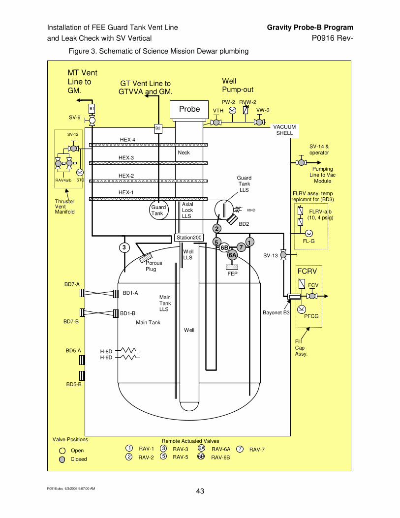
7. The Fill Cap Assembly must be installed at SV-13 (Figure 3)
8. Top Plate heaters must be installed on SMD and be operational.

Installation of FEE Guard Tank Vent Line Gravity Probe-B Program
and Leak Check with SV Vertical P0916 Rev-
P0916.doc 6/3/2002 9:07:00 AM 9
E.6. Optional Non-flight Configurations
The following non-flight modifications of the basic SMD and optional GSE configurations are incidental to the performance of this procedure. Any combination represents an acceptable configuration.
1. The SV is installed in: the SMD transportation and test fixture or in the space vehicle assembly fixture; or the space vehicle tilt dolly.
2. A foreign object and debris shield may cover the upper cone of the SMD. If it is not present, any object that could cause damage to the payload, if dropped, must be tethered.
3. The Vacuum shell pump out port at SV-14 may be connected to the Vacuum Module (P/N 5833816) via a 2-in valve and valve operator and pumping line, with the valve in either the closed position or in the open position. The Vacuum Module pump may be off, actively pumping the pumping line up to a closed SV-14, or actively pumping the vacuum shell
4. If the Vacuum shell operator is not installed, then the vacuum shell valve is closed and capped off.
E.7. Verification/ Success Criteria
N/A
E.8. Payload Constraints and Restrictions
N/A

Installation of FEE Guard Tank Vent Line Gravity Probe-B Program
and Leak Check with SV Vertical P0916 Rev-
P0916.doc 6/3/2002 9:07:00 AM 10
F. Reference Documents
F.1. Drawings
Drawing No. Title
LMMS-5833394 Instrumentation Installation
F.2. Supporting documentation
Document No. Title
LMMC-5835031 GP-B Magnetic Control Plan
GPB-100153C SMD Safety Compliance Assessment
EM SYS229 Accident/Mishap/Incident Notification Process
LMSC-P088357 Science Mission Dewar Critical Design Review
SU/GP-B P0108 Quality Plan
LMMS GPB-100333 Science Mission Dewar Failure Effects and Causes Analysis
SU/GP-B P059 GP-B Contamination Control Plan
SU/GP-B P0879 GP-B Accident/Incident/Mishap Notification Process
F.3. Additional Procedures
Document No. Title
SU/GP-B P0213 Connect Vacuum Module/ Pump on SMD Vacuum Shell
SU/GP-B P0676 Connect Guard Tank Vent Line to Gas Module
SU/GP-B P0875 GP-B Maintenance and Testing at all Facilities
SU/GP-B P0879 Accident/Incident/Mishap Notification Process

Installation of FEE Guard Tank Vent Line Gravity Probe-B Program
and Leak Check with SV Vertical P0916 Rev-
P0916.doc 6/3/2002 9:07:00 AM 11
Operation Number:____________
Date Initiated:____________
Time Initiated:____________
G. Operations
G.1. Perform Preparatory Operations
G.1.1. Verify SU QA notified.
Record: Individual notified __________________,
Date/time ________/________.
G.1.2. Verify NASA representative notified.
Record: Individual notified __________________,
G.1.3. Verify LM SV Operations representative (Frank Mendoza, Norm Bennett) notified of approximate time for RAV-2 operations.
Record: Individual notified __________________,
Date/time ________/________.
G.1.4. Record calibration due dates in Table 1 (Sec. E.4).
G.1.5. Verify that persons actually performing this procedure have initialed their names in Sec. D.3 and the name of the Test Director is circled.
G.1.6. Verify Pre-ops meeting with operations group has been conducted.
G.1.7. Verify Purity of All Sources of Helium Gas
Record serial number on helium bottle/s.
1. ______ 2.______ 3. ______ 4. ______ 5 ______ 6. ______
G.1.8. Verify helium bottle/s have been tested for purity and record Op. Number. Op. Number:_______
Date/time ________/________.
Quality ____________

Installation of FEE Guard Tank Vent Line Gravity Probe-B Program
and Leak Check with SV Vertical P0916 Rev-
P0916.doc 6/3/2002 9:07:00 AM 12
G.2. Connect GTV to GM
G.2.1. Connect GTVA to GM using procedure “Connect Guard Tank Vent to Gas Module, P0676, Record Op number . Note: Stop the procedure at the completion of para. G.6.11, the point at which the UTS is pumping up to a closed GTV-V and with the Guard Tank pressurized at GTV-Va from the helium 6-pack.
G.2.2. Record: Date/Time ______________

Installation of FEE Guard Tank Vent Line Gravity Probe-B Program
and Leak Check with SV Vertical P0916 Rev-
P0916.doc 6/3/2002 9:07:00 AM 13
G.3. Verify Configuration Requirements
G.3.1. Ensure DAS Watch Dog Alarm enabled.
G.3.2. Ensure that Top Plate heaters on SMD are operational.
G.3.3. Verify GSE cabling, excluding P801 and P802 flight cables, are connected between SMD, Electrical Module, Gas Module and Data Acquisition System.
G.3.4. Record MT pressure (STG) ____ torr.
G.3.5. Verify DAS and liquid level alarms enabled and record set points.
1. Main Tank level (“A” or “B”): Record set point _________%
2. Top of lead bag temperature/a – verify [CN 28] on DAS alarm list and set to alarm at T ≤ 6.5 K. Record set point _________K
3. Top of lead bag temperature/b – verify [CN 29] on DAS alarm list and set to alarm at T ≤ 6.5 K. Record set point _________K
4. Relative Guard Tank Pressure – verify [CN46] on DAS alarm list and set to alarm at ∆P ≥ 0.3 torr. Record set point ________torr
5. Relative Main Tank Pressure – verify [CN49] on DAS alarm list and set to alarm at ∆P ≥ 4.0 torr. Record set point ________to
G.3.6. Verify orientation of SMD/SV: is vertical with +Z up.
G.3.7. Verify Main Tank is venting to the room via the Main Tank Vent Cap Assembly (MTVCA) relief valve.
G.3.8. Verify Guard Tank is venting via the GTV-RV of GTVA.
G.3.9. Verify connected/connect the DAS Endevco read out to GTV-G (2 psid) on the GTVA and verify read out and DAS receive appropriate indicated values.
G.3.10. Ensure ion-pump magnet and signal cable installed.
G.3.11. Record Vacuum Shell Pressure.
1. Turn on Vac-ion pump and record time of day _______
2. Use DAS [Monitor Data] for CN 99.
3. When value is steady, record pressure (IP) _______ torr. If pressure is above 1x10⁻⁴ torr, perform procedure P0213, Connect of Vacuum Module / Pump on SMD Vacuum Shell, to connect Vacuum Module and pump out SMD vacuum shell.
ο Pressure is <5x10⁻⁵ torr, continue at step 4.
ο Pressure is >5x10⁻⁵ torr, turn of vac-ion pump and perform P0213, record date/time .

Installation of FEE Guard Tank Vent Line Gravity Probe-B Program
and Leak Check with SV Vertical P0916 Rev-
P0916.doc 6/3/2002 9:07:00 AM 14
4. Exit [Monitor Data] and collect data with [Set Data Interval] to 10 min.
5. When data cycle is complete, turn off Vac-ion pump.
G.3.12. Verify Actuator Control for EV-9 set to “NBP” position.
G.3.13. Record: Date/Time ______________
Quality ___________

Installation of FEE Guard Tank Vent Line Gravity Probe-B Program
and Leak Check with SV Vertical P0916 Rev-
P0916.doc 6/3/2002 9:07:00 AM 15
G.4. Verify Gas-Module Configuration and Record Initial Conditions
G.4.1. Verify valve states as indicated in following Table.
Verify Initial Valve States
Verify Open/Active Verify Closed
Main Tank vent
Not Connected to GM, venting to room SV-9, MTVC-RV MTVC-Va
Guard Tank vent
Connected to GM at “Guard Tank Vent” and pumped by the UTS up to GTV-V
Venting
TV-1, TV-2, EV-5, EV-14, EV-4, EV-7A/B, EV-16
GTV-RV
GTV-V, GTV-Va
Remaining EV valves All other EVs
AV valves APR2, APR2-V All other AVs
G.4.2. Record initial temperatures
1. Top of Lead Bag CN [28] __________ K.
2. Top of Lead Bag CN [29] __________ K.
3. Temperature at bottom of Main Tank CN 09] ________K.
G.4.3. Record pressures.
1. Guard Tank (GTV-G) CN[46]:______ torr (relative to atm.)
2. Main Tank (STG) CN[49]:______ torr. (Endevco on Thruster Vent Manifold)
G.4.4. Record liquid level in Main Tank ______ %.
G.4.5. Record liquid level in Guard Tank ______ %.
G.4.6. Verify Main Tank liquid level is above 35%.
G.4.7. Verify Guard Tank liquid level is above 20%.
G.4.8. Record status of Well pump-out:
ο VTH closed and Well manifold not installed.
ο Well manifold installed, record valve positions and pressure:
VTH ____ , VW-3 _____ , PW-1 _____ torr.
Quality__________

Installation of FEE Guard Tank Vent Line Gravity Probe-B Program
and Leak Check with SV Vertical P0916 Rev-
P0916.doc 6/3/2002 9:07:00 AM 16
G.5. Set Up Data Acquisition System
Note: Refer to DAS operating instructions for information on configurations and mechanics of keyboard/mouse operation.
G.5.1. Verify DAS set to configuration 4Y.
G.5.2. Set DAS to fast scan mode using [other menus], [data config], [fast scan] and [Remove MultScan]
G.5.3. Record directory and data file name .
G.5.4. Start “Special Data Cycle” by using [Other Menus] + [Special Data Col].
G.5.5. Enter CNs: 28, 24, 64, 46 (GTV-G) and 49 (ST-G, Thruster Vent) and 114 (EG-1a).
G.5.6. [Init. Collectn]
G.5.7. [Enter] use default file name.
G.5.8. Record directory and special data file name .
G.5.9. Ensure printer is displaying special Data Cycle data.
G.5.10. Connect/verify connected power supply A1 and A2 to Guard Tank heaters H03D and H-04D.
G.5.11. Turn on power supply A and set outputs A1 and A2 to 0.08 amp current limit.
G.5.12. Verify heater power to H03D and H04D are recorded and plotted at DAS.
G.5.13. Record heater settings in Table G.5
Table G.5 Guard Tank Heater
Date/Time H03D CN64
H04D CN66
GT Temp CN24
Lead Bag CN28
Watt Watt K K
Quality__________

Installation of FEE Guard Tank Vent Line Gravity Probe-B Program
and Leak Check with SV Vertical P0916 Rev-
P0916.doc 6/3/2002 9:07:00 AM 17
G.6. Prepare FEE Guard Tank Vent Line (FGTVL)
G.6.1. Record the bayonet female fit check gap measurements made in LM operations order No. INT-251 for the inboard FEE Guard Tank Vent Line.
1. Maximum gap _________
2. Minimum gap _________
G.6.2. Record the bayonet male fit check gap measurements made in LM operations order No. INT-251 for the outboard end of the FEE Guard Tank Vent Line.
1. Maximum gap _________
2. Minimum gap _________
G.6.3. At a convenient time enter the above values in the Bayonet Usage Book.
G.6.4. Prepare a new bayonet O-ring (Parker Viton 2-027) with a thin layer of Apiezon N vacuum grease. Record: Lot No. ________ , Expiration date __________ .
G.6.5. Install the O-ring into the outlet bayonet O-ring groove of the FGTVL.
G.6.6. Valve configuration: Same as G4.1
Quality__________

Installation of FEE Guard Tank Vent Line Gravity Probe-B Program
and Leak Check with SV Vertical P0916 Rev-
P0916.doc 6/3/2002 9:07:00 AM 18
G.7. Remove GT Short Vent Line
G.7.1. Prepare a No. 5 rubber stopper with a 1 psid relief valve (1/8-in NPT size)
CAUTION
In the following steps the Guard Tank pressure must be prevented from going subatmospheric which could result in air contamination and plugging of the internal Guard Tank vent. Corrective action is to increase the flow rate by raising the Guard Tank heater voltages.
G.7.2. Remove GTSVL from SMD GT vent port (B2) and Immediately install No. 5 stopper/relief valve.
G.7.3. Verify Guard Tank is venting via stopper/RV combination.
G.7.4. Remove O-ring from SMD bayonet and clean O-ring groove with clean room wipes and ethyl/isopropyl alcohol.
G.7.5. Remove stopper assembly and: Immediately insert the male bayonet gauge fit check and using feeler gauges measure gap and record:
Maximum gap _________ Minimum gap _________
G.7.6. Remove tool and reinstall stopper.
G.7.7. Prepare a new bayonet O-ring (Viton 2-027) with a thin layer of Apiezon N vacuum grease. Record: Lot No. ________ , Expiration date __________ .
G.7.8. Install the O-ring into the SMD Guard Tank vent bayonet O-ring.
G.7.9. Remove the Guard Tank Vent Assembly (with GTLVL attached) from the GTSVL and install onto the bayonet outlet for FGTVL. Keep helium purge hose on closed GTV-Va and signal cable on GTV-G.

Installation of FEE Guard Tank Vent Line Gravity Probe-B Program
and Leak Check with SV Vertical P0916 Rev-
P0916.doc 6/3/2002 9:07:00 AM 19
G.7.10. Valve configuration:
Verify Initial Valve States
Verify Open/Active Verify Closed
Main Tank vent
Not Connected to GM, venting to room SV-9, MTVC-RV MTVC-Va
Guard Tank vent
Connected to GM at “Guard Tank Vent” and pumped by the UTS up to GTV-V
TV-1, TV-2, EV-5, EV-14, EV-4, EV-7A/B, EV-16
Venting B2-RV GTV-V, GTV-Va
Remaining EV valves All other EVs
AV valves APR2, APR2-V All other AVs
G.7.11. Record: Date/Time ______________
Quality__________

Installation of FEE Guard Tank Vent Line Gravity Probe-B Program
and Leak Check with SV Vertical P0916 Rev-
P0916.doc 6/3/2002 9:07:00 AM 20
G.8. Install FGTVL
CAUTION In the following steps the Guard Tank pressure must be prevented from going subatmospheric which could result in air contamination and plugging of the internal Guard Tank venting. Corrective action is to increase the flow rate by raising the Guard Tank heater voltages.
CAUTION
Watch the special data collection output to warn of excessive lead bag temperatures. Corrective action is to increase Guard Tank flow by increasing Guard Tank heater voltages.
G.8.1. Perform LM operations order No. INT 251 “Install Guard Tank Vent Line …” up to the point of removing B2 rubber stopper.
G.8.2. Verify helium flow from stopper/relief valve.
NOTE
In the following step ensure helium gas flow out of Guard Tank B2 and out of GTVA (open GTV-Va for purging) as FGTVL is assembled to dewar B2.
G.8.3. Continue with the LM operation.
G.8.4. When the operation is completed verify FGTVL has been purged by Guard Tank outflow and the valve GTV-V and GTV-Va are closed with vent path supplied by GTV-RV.
G.8.5. Record: Date/Time ______________
Quality__________

Installation of FEE Guard Tank Vent Line Gravity Probe-B Program
and Leak Check with SV Vertical P0916 Rev-
P0916.doc 6/3/2002 9:07:00 AM 21
G.9. Preparing Equipment for Leak Detection
G.9.1. Verify SV is vertical, Main Tank is venting to room via SV-9 and Main Tank Vent Cap Assembly relief valve, MTVC-RV
G.9.2. Ensure ‘pump exhaust’ of Gas Module is vented to outside of facility.
G.9.3. Close verify/closed RGA-V.
G.9.4. Install Neon Standard Leak at GTV-Va opening GTV-Va to allow purging of NSL flex hose before making plumbing connection.
G.9.5. Record Neon Standard Leak and calculate leak value:
1. Record original leak value __________ sccs Ne.
2. Record original leak calibration date _______ .
3. Record rate of change in leak value ________ %/year.
4. Calculate present leak value __________ sccs Ne.
G.9.6. Leave GTV-Va open.
G.9.7. Verify the configuration of the Vacuum Module, Gas Module, UTS, RGA, Neon Standard Leak and SMD is as shown in Figures 1b with valve configuration as given below.
G.9.8. Valve configuration:
Open/Active Closed
Main Tank vent
Not Connected to GM SV-9, MTVC-RV
Guard Tank vent
Connected to GM at “Guard Tank Vent” and pumped by the UTS up to GTV-V
TV-1, TV-2, EV-5, EV-14, EV-4, EV-7A/B, EV-16
Venting GTV-RV GTV-V, GTV-Va
Remaining EV valves All other EV valves
Neon leak valves GTV-Va RGA-SOV, RGA-LV, NSL-V
GSE RAVs RAV-3 All other RAVs
SV RAVs RAV-6B RAV-2
Quality__________

Installation of FEE Guard Tank Vent Line Gravity Probe-B Program
and Leak Check with SV Vertical P0916 Rev-
P0916.doc 6/3/2002 9:07:00 AM 22
G.10. Remove Liquid Helium from Guard Tank
G.10.1. Begin recording data in Table G.10.
G.10.2. Input comment to DAS “Begin Guard Tank boil-off”.
G.10.3. Verify heater power to H03D and H04D are recorded and plotted by DAS.
G.10.4. When Guard Tank temperature [CN24] reaches 35 +/-5 K, power off heaters.
Table G.10 Guard Tank boil-off Data
Date/Time H03D H04D GT Temp CN24
Lead Bag CN28
GT LLS
Watt watt K K %
G.10.5. Record: Date/Time ______________
Quality__________
G.11. Pump Guard Tank with AP-1
G.11.1. Put Gas Module control panel into INTLK DEFEAT.
G.11.2. Turn on/verify on AP-1.
G.11.3. Close EV-5.
G.11.4. Verify RGA-LV closed.
G.11.5. Open RGA-SOV slowly.
G.11.6. Open RGA-V slowly.
G.11.7. Open AV-6: AP-1 now pumping up to closed GTV-V.
G.11.8. Open GTV-V gradually, keeping pressure at EG-1a to less than 20 torr.
G.11.9. Enter comment to DAS: “Begin pumping Guard Tank”.
Installation of FEE Guard Tank Vent Line Gravity Probe-B Program
and Leak Check with SV Vertical P0916 Rev-
P0916.doc 6/3/2002 9:07:00 AM 23
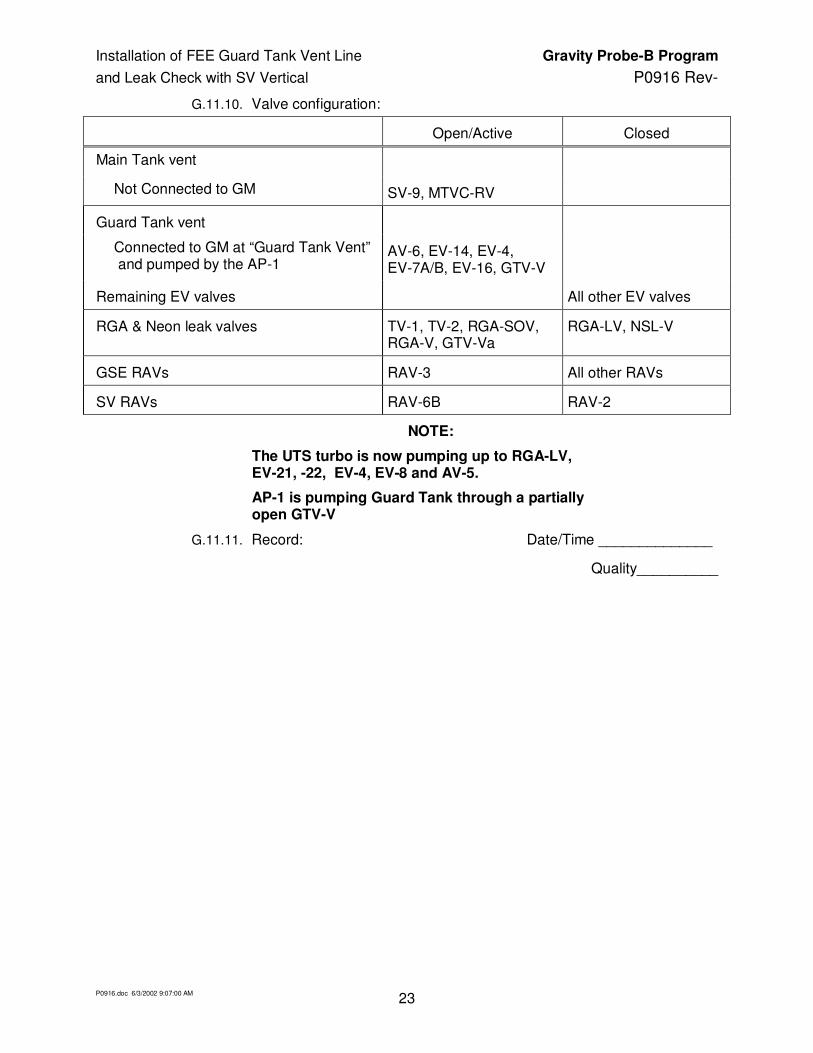
G.11.10. Valve configuration:
Open/Active Closed
Main Tank vent
Not Connected to GM SV-9, MTVC-RV
Guard Tank vent
Connected to GM at “Guard Tank Vent” and pumped by the AP-1
AV-6, EV-14, EV-4, EV-7A/B, EV-16, GTV-V
Remaining EV valves All other EV valves
RGA & Neon leak valves TV-1, TV-2, RGA-SOV, RGA-V, GTV-Va
RGA-LV, NSL-V
GSE RAVs RAV-3 All other RAVs
SV RAVs RAV-6B RAV-2
NOTE:
The UTS turbo is now pumping up to RGA-LV, EV-21, -22, EV-4, EV-8 and AV-5.
AP-1 is pumping Guard Tank through a partially open GTV-V
G.11.11. Record: Date/Time ______________
Quality__________

Installation of FEE Guard Tank Vent Line Gravity Probe-B Program
and Leak Check with SV Vertical P0916 Rev-
P0916.doc 6/3/2002 9:07:00 AM 24
G.12. Configure for Neon Leak Detection
G.12.1. Enter comment to DAS “ Start neon leak at 50 torr”.
G.12.2. Power-on RGA.
G.12.3. Verify RGA-SOV is open.
G.12.4. Adjust RGA-LV to maintain TG-1 between 1E-5 to 8E-5 torr.
G.12.5. Set up RGA in leak detect mode for mass 20.
G.12.6. Start data recording in Table 1.
G.12.7. Bag/verify bagged, connections at GTVA/GTLVL, FGTVL/GTVA and FGTVL/B2 bayonet.
G.12.8. Install/verify installed regulator on Neon supply Bottle.
G.12.9. When GTV-G is approximately 50 torr proceed with the following steps
G.12.10. Valve configuration:
Open/Active Closed
Main Tank vent
Not Connected to GM SV-9, MTVC-RV
Guard Tank vent
Connected to GM at “Guard Tank Vent” and pumped by the UTS
AV-6, EV-14, EV-4, EV-7A/B, EV-16, GTV-V
Remaining EV valves All other EV valves
RGA & Neon leak valves TV-1, TV-2, RGA-V, RGA-SOV, RGA-LV, GTV-Va,
NSL-V
GSE RAVs RAV-3 All other RAVs
SV RAVs RAV-6B RAV-2
Quality__________

Installation of FEE Guard Tank Vent Line Gravity Probe-B Program
and Leak Check with SV Vertical P0916 Rev-
P0916.doc 6/3/2002 9:07:00 AM 25
G.13. Leak Check at 50 Torr
G.13.1. Leak Check GTVA/GTLVL Bayonet at 50 Torr: Date/Time _
1. Record data in Table 1.
2. Open/verify open RGA-SOV.
3. Adjust RGA-LV to maintain TG-1 to 5 +/- 1x10⁻⁵ torr.
4. Verify RGA is in leak check mode for mass 20.
5. Record steady state data in Table 1 and below: Record TG-1 torr, IRGA amp.
6. Introduce neon gas into bagged GTV bayonet for 2 mins.
7. Record steady state data in Table 1 and below: Record TG-1 torr, IRGA amp.
8. Comments:
G.13.2. Leak Check FGTVL/GTVA bayonet at 50 Torr Date/Time .
1. Open/verify open RGA-SOV.
2. Adjust RGA-LV to maintain TG-1 to 5 +/- 1x10⁻⁵ torr.
3. Verify RGA is in leak check mode for mass 20.
4. Record steady state data in Table 2 and below: Record TG-1 torr, IRGA amp.
5. Introduce neon gas into bagged FGTVL/GTVA bayonet for 2 mins.
6. Record reading amps.
7. Comments:
G.13.3. Leak Check FGTVL/B2 bayonet at 50 Torr Date/Time .
1. Adjust RGA-LV to maintain TG-1 to 5 +/- 1x10⁻⁵ torr.
2. Introduce neon gas into bagged FGTVL/B2 bayonet for 2 mins.
3. Record steady state data in Table 2 and below: Record TG-1 torr, IRGA amp.
4. Comments:
5. Enter comment to DAS “End 50 Torr Leak Test”.
Quality__________

Installation of FEE Guard Tank Vent Line Gravity Probe-B Program
and Leak Check with SV Vertical P0916 Rev-
P0916.doc 6/3/2002 9:07:00 AM 26
G.14. Pumping Guard Tank to Vacuum and Leak Check
G.14.1. When EG-1a is between 1 and 10 torr, and GTV-V is fully open:
1. Power off RGA and TG-1.
2. Close RGA-LV and RGA-SOV.
3. Close AV-6.
G.14.2. Open EV-5: now pumping Guard Tank with UTS turbo.
G.14.3. When TG-3 < 1 torr power on TG-1.
G.14.4. Power on TG-1.
G.14.5. Record: TG-1 torr, VG-4 torr Date/Time _
G.14.6. When TG-1 is less than 8E-5 proceed.
G.14.7. Record TG-1 torr. Date/Time
G.14.8. Power on RGA and place in leak check mode for mass 20.
Calibrate RGA at Low Pressure
Note: The neon standard leak has a value of ________ sccs Ne, ref. G5.9.
G.14.9. Open NSL-V.
G.14.10. Record steady state data in Table 1 and below: Record TG-1 torr, IRGA amp.
G.14.11. Close NSL-V
G.14.12. Record steady state data in Table 1 and below: Record TG-1 torr, IRGA amp.
G.14.13. Open NSL-V.
G.14.14. Record steady state data in Table 1 and below: Record TG-1 torr, IRGA amp.
G.14.15. Close NSL-V
G.14.16. Record steady state data in Table 1 and below: Record TG-1 torr, IRGA amp.
G.14.17. When time allows calculate RGA sensitivity, 1.5X10⁻⁶ sccs/change in amps, sccs/amp.
Quality__________

Installation of FEE Guard Tank Vent Line Gravity Probe-B Program
and Leak Check with SV Vertical P0916 Rev-
P0916.doc 6/3/2002 9:07:00 AM 27
G.15. Leak Check at low pressure
NOTE:
Maximum Leak rate shall be less than 1X10⁻⁶
sccs Neon
G.15.1. Leak Check GTVA/GTLVL Bayonet Date/Time
1. Open/verify open RGA-SOV.
2. Adjust RGA-LV to maintain TG-1 on same value as used for low pressure calibration above.
3. Verify RGA is in leak check mode for mass 20.
4. Record steady state data in Table 1 and below: Record TG-1 torr, IRGA amp.
5. Introduce neon gas into bagged GTV bayonet for 2 mins.
6. Record steady state data in Table 1 and below: Record TG-1 torr, IRGA amp.
7. Calculate leak rate using RGA sensitivity determined above sccs Ne.
8. Calculate leak rate: sccs Ne
9. Verify leak rate is less than 1x10⁻⁶ sccs Ne.
10. Comments:
G.15.2. Leak Check FGTVL/GTVA bayonet Date/Time .
1. Verify RGA is in leak check mode for mass 20.
2. Record steady state data in Table 2 and below: Record TG-1 torr, IRGA amp.
3. Introduce neon gas into bagged FGTVL/GTVA bayonet for 2 mins.
4. Record reading amps.
5. Calculate leak rate: sccs Ne
6. Verify leak rate is less than 1x10⁻⁶ sccs Ne.
7. Comments:

Installation of FEE Guard Tank Vent Line Gravity Probe-B Program
and Leak Check with SV Vertical P0916 Rev-
P0916.doc 6/3/2002 9:07:00 AM 28
G.15.3. Leak Check FGTVL/B2 bayonet Date/Time .
1. Adjust RGA-LV to maintain TG-1 on same value as used for low pressure calibration above.
2. Introduce neon gas into bagged FGTVL/B2 bayonet for 2 mins.
3. Record steady state data in Table 1 and below: Record TG-1 torr, IRGA amp.
4. Calculate leak rate: sccs Ne
5. Verify leak rate is less than 1x10⁻⁶ sccs Ne.
6. Comments:
G.15.4. Enter comment to DAS “End low pressure Ne Leak Test”.
G.15.5. Spray Ne around the GTLVL/HEX bayonet and adjacent GM joints up to EV-13 and EV-16.
G.15.6. Record steady state data in Table 1 and below: Record TG-1 torr, IRGA amp.
G.15.7. Turn off RGA.
G.15.8. Close/verify closed RGA-LV.
G.15.9. Close/verify closed RGA-SOV, RGA-V.
G.15.10. Close GTV-Va.
G.15.11. Valve configuration:
Open/Active Closed
Main Tank vent
Not Connected to GM SV-9, MTVC-RV
Guard Tank vent
Connected to GM at “Guard Tank Vent” and pumped by the UTS
TV-1, TV-2, EV-5, EV-14, EV-4, EV-7A/B, EV-16, GTV-V
Remaining EV valves All other EV valves
RGA & Neon leak valves GTV-Va, NSL-V, RGA-SOV, RGA-LV, RGA-V
GSE RAVs RAV-3 All other RAVs
SV RAVs RAV-6B RAV-2
Quality__________
Installation of FEE Guard Tank Vent Line Gravity Probe-B Program
and Leak Check with SV Vertical P0916 Rev-
P0916.doc 6/3/2002 9:07:00 AM 29
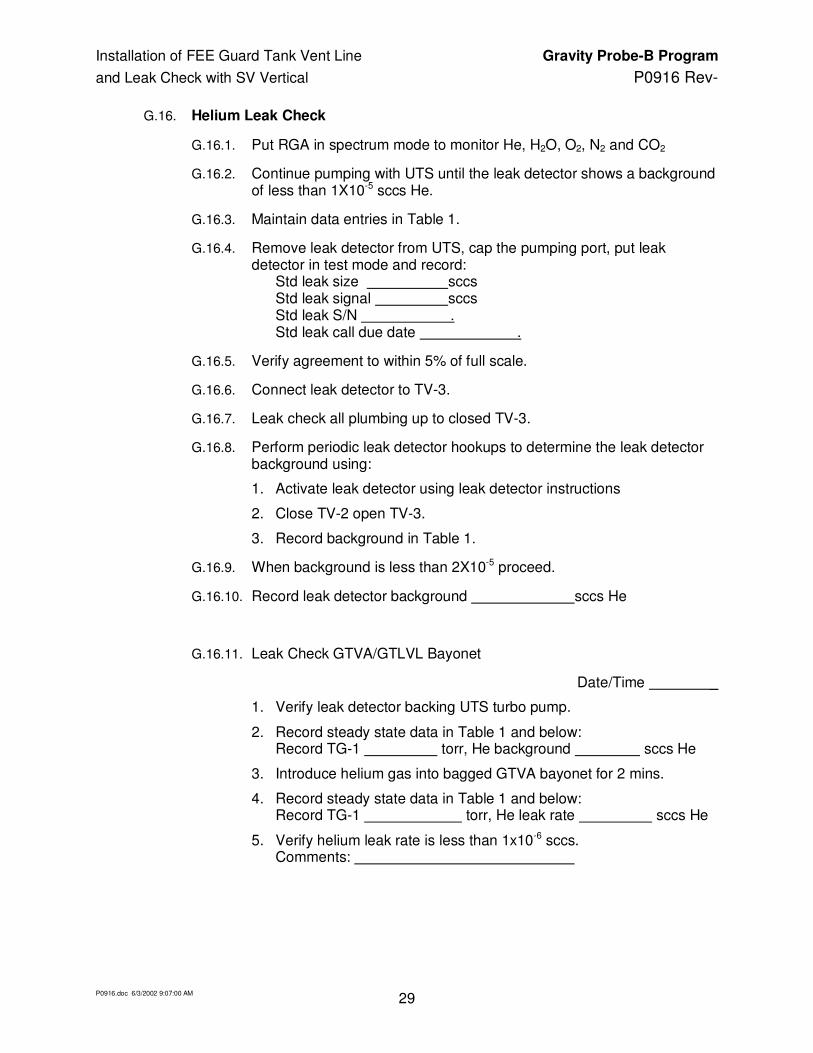
G.16. Helium Leak Check
G.16.1. Put RGA in spectrum mode to monitor He, H2O, O2, N2 and CO2
G.16.2. Continue pumping with UTS until the leak detector shows a background of less than 1X10⁻⁵ sccs He.
G.16.3. Maintain data entries in Table 1.
G.16.4. Remove leak detector from UTS, cap the pumping port, put leak detector in test mode and record: Std leak size sccs Std leak signal sccs Std leak S/N . Std leak call due date .
G.16.5. Verify agreement to within 5% of full scale.
G.16.6. Connect leak detector to TV-3.
G.16.7. Leak check all plumbing up to closed TV-3.
G.16.8. Perform periodic leak detector hookups to determine the leak detector background using:
1. Activate leak detector using leak detector instructions
2. Close TV-2 open TV-3.
3. Record background in Table 1.
G.16.9. When background is less than 2X10⁻⁵ proceed.
G.16.10. Record leak detector background sccs He
G.16.11. Leak Check GTVA/GTLVL Bayonet
Date/Time _
1. Verify leak detector backing UTS turbo pump.
2. Record steady state data in Table 1 and below: Record TG-1 torr, He background sccs He
3. Introduce helium gas into bagged GTVA bayonet for 2 mins.
4. Record steady state data in Table 1 and below: Record TG-1 torr, He leak rate sccs He
5. Verify helium leak rate is less than 1x10⁻⁶ sccs. Comments:
Installation of FEE Guard Tank Vent Line Gravity Probe-B Program
and Leak Check with SV Vertical P0916 Rev-
P0916.doc 6/3/2002 9:07:00 AM 30
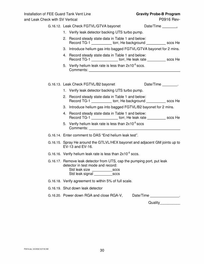
G.16.12. Leak Check FGTVL/GTVA bayonet Date/Time .
1. Verify leak detector backing UTS turbo pump.
2. Record steady state data in Table 1 and below: Record TG-1 torr, He background sccs He
3. Introduce helium gas into bagged FGTVL/GTVA bayonet for 2 mins.
4. Record steady state data in Table 1 and below: Record TG-1 torr, He leak rate sccs He
5. Verify helium leak rate is less than 2x10⁻⁶ sccs. Comments:
G.16.13. Leak Check FGTVL/B2 bayonet Date/Time .
1. Verify leak detector backing UTS turbo pump.
2. Record steady state data in Table 1 and below: Record TG-1 torr, He background sccs He
3. Introduce helium gas into bagged FGTVL/B2 bayonet for 2 mins.
4. Record steady state data in Table 1 and below: Record TG-1 torr, He leak rate sccs He
5. Verify helium leak rate is less than 2x10⁻⁶ sccs Comments:
G.16.14. Enter comment to DAS “End helium leak test”.
G.16.15. Spray He around the GTLVL/HEX bayonet and adjacent GM joints up to EV-13 and EV-16.
G.16.16. Verify helium leak rate is less than 2x10⁻⁶ sccs.
G.16.17. Remove leak detector from UTS, cap the pumping port, put leak detector in test mode and record: Std leak size sccs Std leak signal sccs
G.16.18. Verify agreement to within 5% of full scale.
G.16.19. Shut down leak detector
G.16.20. Power down RGA and close RGA-V, Date/Time .
Quality__________

Installation of FEE Guard Tank Vent Line Gravity Probe-B Program
and Leak Check with SV Vertical P0916 Rev-
P0916.doc 6/3/2002 9:07:00 AM 31
G.17. Re-pressurize Guard Tank with Helium Gas from Main Tank
Date/Time____________
G.17.1. Record: EG1b torr.
G.17.2. Close EV-5, EV-14, and EV-4.
G.17.3. Close TV-1 and shut down UTS.
G.17.4. Valve configuration:
Open/Active Closed
Main Tank vent
Not Connected to GM SV-9, MTVC-RV
Guard Tank vent
Locked up to GM manifold EV-16, GTV-V
Remaining EV valves EV-7A/B All other EV valves
RGA & Neon leak valves GTV-Va, NSL-V, RGA-SOV, RGA-LV, RGA-V
GSE RAVs RAV-3 All other RAVs
SV RAVs RAV-6B RAV-2
Quality__________
G.18. Prepare Fill Line
G.18.1. Verify installed/install 1-in. pumping line from Access-1 of Gas Module to FCV of FCA.
G.18.2. Turn on pump AP-1.
G.18.3. Open AV-8 and AV-3.
G.18.4. Open valve FCV and evacuate to 20 mtorr as measured at AG-2.
G.18.5. Close AV-8.
G.18.6. Open AV-1 and adjust AV-9 to give 1 psig at AG-1.
G.18.7. Close AV-1
G.18.8. Open AV-8 and evacuate to 20 mtorr. as measured at AG-2.
G.18.9. Close AV-8 and FCV.
G.18.10. Once the pressure in the Fill Cap Assembly has stabilized, record
Fill Cap Assembly pressure (FCG): __________ torr.
G.18.11. Open valve SV-13 to bring Fill Cap Assembly up to SMD Fill line pressure and record
Fill line pressure (FCG): _______ torr.
Quality__________

Installation of FEE Guard Tank Vent Line Gravity Probe-B Program
and Leak Check with SV Vertical P0916 Rev-
P0916.doc 6/3/2002 9:07:00 AM 32
G.19. Open RAV-1
G.19.1. Enter comment to DAS “Start repress of GT”. Date/Time _.
G.19.2. Verify all selector switches are off.
G.19.3. Power up RAV power supply to 28 volt at 1.9 a.
G.19.4. Power up RAV controller No. 1.
G.19.5. Position selection switch to RAV-1.
G.19.6. Record initial switch status: Open: θ θ Closed: θ θ
G.19.7. Activate controller No. 1 and record:
1. run time: ________ seconds
2. current draw: ______ amp
3. time of day: _______ hrs
G.19.8. Record final switch status: Open: θ θ Closed: θ θ
G.19.9. Record operation in RAV log book.
G.19.10. Record FCG torr
G.19.11. Record EG-1a torr
Quality__________
G.20. Open RAV-2
G.20.1. Verify closed FCV.
G.20.2. Request LM personnel install arming plug for RAV-2
G.20.3. Request LM SV Operations open RAV-2.
G.20.4. Record FCG torr
G.20.5. Record EG-1a torr
G.20.6. Verify RAV-2 is open by near coincident with SV open command of rise of Guard Tank pressure to the Main Tank pressure (FCG).
G.20.7. Record FCG torr
G.20.8. Record EG-1a torr
Quality__________

Installation of FEE Guard Tank Vent Line Gravity Probe-B Program
and Leak Check with SV Vertical P0916 Rev-
P0916.doc 6/3/2002 9:07:00 AM 33
G.21. Close RAV-2
G.21.1. Request LM SV Operations close RAV-2.
G.21.2. Request LM personnel remove arming plug for RAV-2
G.21.3. Verify by pressure rise in FCG that RAV-2 is closed.
G.21.4. Record:
1. FCG torr
2. EG-1a torr
G.21.5. Verify APR-2 is adjusted to ~.5 psig .
G.21.6. Open EV-23 to regulate pressure to Guard Tank.
G.21.7. Adjust APR-2 gradually to ~2 psig, watching CN28 for temperature excedance.
G.21.8. Valve configuration:
Open/Active Closed
Main Tank vent
Not Connected to GM SV-9, MTVC-RV
Guard Tank vent
Pressurized by APR-2 EV-16, EV-23, APR-2, GTV-V, GTV-RV
GTV-Va
Remaining EV valves EV-7A/B All other EV valves
Fill line FCG, SV-13, AV-1, AV-9
GSE RAVs RAV-1, RAV-3 All other RAVs
SV RAVs RAV-6B RAV-2
Quality__________
G.22. Close RAV-1 and Pump Fill Line
G.22.1. Verify FCV and all AVs closed.
G.22.2. Open AV-3 and AV-8.
G.22.3. Open FCV.
G.22.4. When FCG < 20 mtorr, close FCV.
G.22.5. Open SV-13, record FCG .

Installation of FEE Guard Tank Vent Line Gravity Probe-B Program
and Leak Check with SV Vertical P0916 Rev-
P0916.doc 6/3/2002 9:07:00 AM 34
G.22.6. Close RAV-1.
1. Record initial switch status: Open: θ θ Closed: θ θ
2. Activate controller No. 1 and record:
a. run time: seconds
b. current draw: ______ amp
c. time of day: _______
Immediately:
3. Verify SV-13 open
4. Record FCG torr
5. Open FCV: now pumping fill line with AP-1.
6. Record final switch status: Open: θ θ Closed: θ θ
7. Record operation in RAV log book. 8. Position selection switch to off.
9. Power down RAV controller No. 1.
10. Power off RAV power supply.
G.22.7. Record FCG torr, EG-1a torr.
G.22.8. Record: Date/Time ______________
Quality__________

Installation of FEE Guard Tank Vent Line Gravity Probe-B Program
and Leak Check with SV Vertical P0916 Rev-
P0916.doc 6/3/2002 9:07:00 AM 35
G.23. Pump Fill Line
1. When AG-2b < 20 mtorr,
2. Record AG-2b torr.
3. Close SV-13, torquing to 60 in-lb.
4. Close AV-8.
G.23.2. Backfill with helium gas via AV-1 and AV-9 to 1.5 psig as indicated by AG-1
G.23.3. Close FCV.
G.23.4. Close AV-1.
G.23.5. Open AV-8: pump line to vacuum.
G.23.6. When AG-2b < 20 mtorr
1. Close AV-8
2. Close AV-3.
G.23.7. Record FCG pressure for 30 minutes:
G.23.8. Date:
G.23.9. Time
G.23.10. FCG (torr)
G.23.11. Verify no leakage at SV-13 into fill line.
Quality__________

Installation of FEE Guard Tank Vent Line Gravity Probe-B Program
and Leak Check with SV Vertical P0916 Rev-
P0916.doc 6/3/2002 9:07:00 AM 36
G.24. Final Configuration
G.24.1. Valve configuration:
Open/Active Closed
Main Tank vent
Not Connected to GM SV-9, MTVC-RV
Guard Tank vent
Pressurized by APR-2 EV-16, EV-23, APR-2, GTV-V
GTV-Va
Remaining EV valves EV-7A/B All other EV valves
Fill line FCV, SV-13, AV-1, AV-9
GSE RAVs RAV-3 All other RAVs
SV RAVs RAV-6B RAV-2
G.24.2. Input comment to DAS “GT leak check completed”.
G.24.3. Stop DAS Special Data Cycle.
G.24.4. Remove pumping line between Access 1 and FCV.
Section G.25 complete. Quality__________
G.25. Configuration of Dewar and GSE
G.25.1. Record the Main Tank liquid level (LL-1D or LL-2D): _________ %
G.25.2. Record the following pressures:
1. Main Tank pressure (EG-3): ______ torr
2. Guard Tank pressure (EG-1a/GTVG): ______ torr
Quality__________
G.26. Setting up Data Acquisition
Note: Refer to Operating Instructions for mechanics of DAS keyboard/mouse operations.
G.26.1. Set DAS to configuration choice 4Y.
G.26.2. Stop Special Data Cycle by using [Other Menus] + [Special Data Col] + [ Stop Data Col].
G.26.3. Record Vacuum Shell Pressure.

Installation of FEE Guard Tank Vent Line Gravity Probe-B Program
and Leak Check with SV Vertical P0916 Rev-
P0916.doc 6/3/2002 9:07:00 AM 37
1. Turn on Vac-ion pump and record time of day _______ .
2. Use DAS [Monitor Data] for CN 99.
3. When value is steady, record pressure (IP) _______ torr.
4. Exit [Monitor Data] and collect data with [Set Data Interval] to 15 min.
5. When data cycle is complete, turn off Vac-ion pump.
G.26.4. Set DAS data cycle interval to 15 minutes.
G.26.5. Set Main Tank Liquid Level sampling interval to 10 minutes.
G.26.6. Confirm that the liquid level sensors are set at a sampling rate of 10 minutes or turned off.
G.26.7. Confirm that Vac-ion pump is off.
G.26.8. Enable/verify enabled the alarms on the Main Tank and Well Liquid Level Sensors.
G.26.9. Verify enabled the DAS alarm and record the set points:
a) CN ____, Level _____ d) Main Tank Level: ______ %
b) CN ____, Level _____ e) Guard Tank Level: ______ %
c) CN ____, Level _____
G.26.10. Ensure DAS watchdog timer and alarm enabled.
Quality .
H. Procedure Completion
Completed by:
Witnessed by:
Date:
Time:
Quality Manager: Date
Payload Test Director: Date

Installation of FEE Guard Tank Vent Line Gravity Probe-B Program
and Leak Check with SV Vertical P0916 Rev-
P0916.doc 6/3/2002 9:07:00 AM 38
Table 1 Neon leak Data
Date/Time Neon
Amp
EG-1a
Torr
TG-1
torr
EG-1a
torr
FCG
Torr-diff
Comments

Installation of FEE Guard Tank Vent Line Gravity Probe-B Program
and Leak Check with SV Vertical P0916 Rev-
P0916.doc 6/3/2002 9:07:00 AM 39
Figure 1a. Schematic of Gas Module Plumbing at Start of FEE Guard Tank Vent Line Install
EFM-1 ERV-1 (1/3 psi)
EV-6 EV-15
EV-16
EV-17
EG-1a 1000 torr
Cap
EG-1b conv
EV-7A
EV-7B
EV-4
Pump
Out
Vent Output
EV-8 EV-5
EV-10 EG-3 1000 torr
Cap
ERV-4b 4.0 psi
ERV-4a 2.0 psi
EH-1
MainTank Vent
EV-9
ERV-3b 4.0 psi
ERV-3a 2.0 psi
ERV-2b 4 psi
ERV-2a 2.0 psi
Guard Tank Vent
EV-11 Well Vent
AV-6
Pump Exhaust
(Vent Outside)
AP-1 Vane Pump
AV-8
AG-1 30 in.
to 30 psi AG-2b conv
AV-10
AG-2a Cap 1000 torr
AV-3
AV-1
ARV-1 2.0 psi
AV-2
ARV-2 2.0 psi
AV-4 AV-7 Access-2
LHe Supply Dewar
Access-1
EV-13
EV-18
EV-12 EG-2 100 torr
Cap
ERV-5 (1/3 psi) EV-19
EH-2
ERV-6 (1/3 psi)
EV-21
EV-23
EV-22
EV-20
EV-14
EV-24
He Gas Supply In
AV-9
AG-3
To “a”
To “a”
APR-1
He Gas Out
M
M
AF1
AV-5 APR-2V APR-2
APR-2G
He gas out
APR-3V APR-3 APR-3G
He gas out
APR-4V APR-4 APR-4G He gas out
AV-11
EFM-2
RGA-LV
RGA-SOV
Access-3
EFM-3
He Gas Supply
UTS
Leak Det.
TV-1
GTV-V
B2 Guard Tank Baynt
GTV-Va
GTV-G
To FCV
RGA-V RGA
FEE GTVL OR
GTSVL

Installation of FEE Guard Tank Vent Line Gravity Probe-B Program
and Leak Check with SV Vertical P0916 Rev-
P0916.doc 6/3/2002 9:07:00 AM 40
Figure 1b. Schematic of Gas Module Plumbing for Neon Leak Detection of Guard Tank Vent
EFM-1 ERV-1 (1/3 psi)
EV-6 EV-15
EV-16
EV-17
EG-1a 1000 torr
Cap
EG-1b conv
EV-7A
EV-7B
EV-4
Pump
Out
Vent Output
EV-8 EV-5
EV-10 EG-3 1000 torr
Cap
ERV-4b 4.0 psi
ERV-4a 2.0 psi
EH-1
MainTank Vent
EV-9
ERV-3b 4.0 psi
ERV-3a 2.0 psi ERV-2b
4 psi
ERV-2a 2.0 psi
Guard Tank Vent
EV-11 Well Vent
AV-6
Pump Exhaust
(Vent Outside)
AP-1 Vane Pump
AV-8
AG-1 30 in.
to 30 psi AG-2b conv
AV-10
AG-2a Cap 1000 torr
AV-3
AV-1
ARV-1 2.0 psi
AV-2
ARV-2 2.0 psi
AV-4 AV-7 Access-2
LHe Supply Dewar
Access-1
EV-13
EV-18
EV-12 EG-2 100 torr
Cap
ERV-5 (1/3 psi) EV-19
EH-2
ERV-6 (1/3 psi)
EV-21
EV-23
EV-22
EV-20
EV-14
EV-24
He Gas Supply In
AV-9
AG-3
To “a”
To “a”
APR-1
He Gas Out
M
M
AF1
AV-5 APR-2V APR-2
APR-2G
He gas out
APR-3V APR-3 APR-3G
He gas out
APR-4V APR-4 APR-4G He gas out
AV-11
EFM-2
RGA-LV
RGA-SOV
Access-3
EFM-3
He Gas Supply
UTS
Leak Det.
TV-1
GTV-V
B2 Guard Tank Baynt
NSL-V
GTV-Va
GTV-G
To FCV
NEON STD. LEAK
RGA-V RGA
FEE GTVL OR
GTSVL
GTLVL

Installation of FEE Guard Tank Vent Line Gravity Probe-B Program
and Leak Check with SV Vertical P0916 Rev-
P0916.doc 6/3/2002 9:07:00 AM 41
Figure 2 Gas Module and Vent lines connected to SMD
Main Tank Vent Cap Assy
SV-9
GTV-RV
GTSVL-RV 4+0.3 psid
Guard Tank Short Vent Line OR FGTVL
Guard Tank Long Vent Line
GAS
MODULE
MTFC-RV 0.5 psid
Endevco Pressure Transducer
SV-12
GTVA
STG 15 psia
GTV-Va
GTV-V
GTV-G
Bayonet fitting
MTFC-V
SMD
RAV-4A/B

Installation of FEE Guard Tank Vent Line Gravity Probe-B Program
and Leak Check with SV Vertical P0916 Rev-
P0916.doc 6/3/2002 9:07:00 AM 42
Figure 2 Utility Pump System with RGA for Neon leak detection
RGA-SOVShutoff Valve
TV-5Let-upvalve4" Turbo
LEAKDETECTORRough Pump
ColdCathodeGauge
TV-3ForelineValve
GateValve
1000 T
10 T
UTILITYTURBOSYSTEM
ISO 100to KF 25
PiraniGauge
TV-1
TG-2
TG-4
TG-3
RGA-V
RGA
TV-4
RGA-LVLeak Valve
TV-2
BypassValve
TG-1
EV-21
ToPump
EV-14
EV-5
EV-4
Access 3
GASMODULE
EV-8
AV-5
EV-22
Installation of FEE Guard Tank Vent Line Gravity Probe-B Program
and Leak Check with SV Vertical P0916 Rev-
P0916.doc 6/3/2002 9:07:00 AM 43
Figure 3. Schematic of Science Mission Dewar plumbing
3
FEP
2
5 6B 7
1
Open
Neck Tube
Closed
Valve Positions
Guard Tank
GT Vent Line to GTVVA and GM.
MT Vent Line to GM.
Well Pump-out Manifold
SV-9
Main Tank
Well
Porous Plug
Well LLS
H-8D H-9D
SV-13
PFCG
FCV
Fill Cap Assy.
6A RAV-6A 1 RAV-1 3 RAV-3
5 RAV-5 2 RAV-2
7 RAV-7
6B RAV-6B
Remote Actuated Valves
FCRV
SV-12
STG
Thruster Vent Manifold
Pumping Line to Vac
Module
SV-14 & operator
Bayonet B3
Guard Tank LLS
Main Tank LLS
FLRV-a,b (10, 4 psig)
FL-G
FLRV assy. temp replcmnt for (BD3)
BD2
BD1-A
BD1-B
BD7-A
BD7-B
BD5-A
BD5-B
Axial Lock LLS
Probe
HEX-4
HEX-3
HEX-2
HEX-1
VTH VW-3
PW-2 RVW-2
VACUUM SHELL
Station200
H04D
RAV4a/b
6A
B2
B1
Installation of FEE Guard Tank Vent Line Gravity Probe-B Program
and Leak Check with SV Vertical P0916 Rev-
P0916.doc 6/3/2002 9:07:00 AM 44
I. Appendices
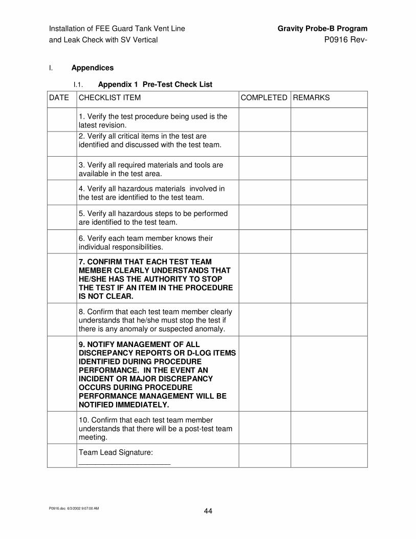
I.1. Appendix 1 Pre-Test Check List
DATE CHECKLIST ITEM COMPLETED REMARKS
1. Verify the test procedure being used is the latest revision.
2. Verify all critical items in the test are identified and discussed with the test team.
3. Verify all required materials and tools are available in the test area.
4. Verify all hazardous materials involved in the test are identified to the test team.
5. Verify all hazardous steps to be performed are identified to the test team.
6. Verify each team member knows their individual responsibilities.
7. CONFIRM THAT EACH TEST TEAM MEMBER CLEARLY UNDERSTANDS THAT HE/SHE HAS THE AUTHORITY TO STOP THE TEST IF AN ITEM IN THE PROCEDURE IS NOT CLEAR.
8. Confirm that each test team member clearly understands that he/she must stop the test if there is any anomaly or suspected anomaly.
9. NOTIFY MANAGEMENT OF ALL DISCREPANCY REPORTS OR D-LOG ITEMS IDENTIFIED DURING PROCEDURE PERFORMANCE. IN THE EVENT AN INCIDENT OR MAJOR DISCREPANCY OCCURS DURING PROCEDURE PERFORMANCE MANAGEMENT WILL BE NOTIFIED IMMEDIATELY.
10. Confirm that each test team member understands that there will be a post-test team meeting.
Team Lead Signature: ______________________

Installation of FEE Guard Tank Vent Line Gravity Probe-B Program
and Leak Check with SV Vertical P0916 Rev-
P0916.doc 6/3/2002 9:07:00 AM 45
I.2. Appendix 2 Post-Test Check List
DATE CHECKLIST ITEM COMPLETED
REMARKS
1. Verify all steps in the procedure were successfully completed.
2. Verify all anomalies discovered during testing are properly documented.
3. Ensure management has been notified of all major or minor discrepancies.
4. Ensure that all steps that were not required to be performed are properly identified.
5. If applicable sign-off test completion.
6. Verify all RAV valve operations have been entered in log book
7. Verify the as-run copy of procedure has been filed in the appropriate binder
Team Lead Signature: ______________________

Installation of FEE Guard Tank Vent Line Gravity Probe-B Program
and Leak Check with SV Vertical P0916 Rev-
P0916.doc 6/3/2002 9:07:00 AM 46
I.3. Appendix 3– Contingency Responses
Condition Circumstance Response
1 Power Failure
Any time Wait for power restoration
Note: the DAS computer will continue to function for several hours, however no data will be collected
DAS computer still operating:
Reset GM valving per the last configuration in procedure and resume procedure
DAS computer not operating:
Reboot computer and launch DRP_SMD and select auto startup option
Reset GM valving per the last configuration in procedure and resume procedure
2
Temperature limits (CN 28 or 29) exceeded
ANY TIME Lower inflow of helium gas to Guard Tank
OR,
INCREASE MAIN TANK VENTING
Open MTVC-V momentarily or if problem persists see 3 below
3
ANY TIME PROMOTE INCREASE IN MAIN TANK VENTING
Power up heater at H08D or H0-9D and starting at 15 vdc input increase power until increased flow has cooled the problem area
4
Burst disk rupture (MT/GT)
ANY TIME Evacuate room