installation of hydraulic kit std controls w/ standard … mio-h29rrg048b001 rev a g&b...
TRANSCRIPT

BULLETIN MIO-H29RRG048B001 REV A
G&B Specialties Inc. 535 West 3rd Street, Berwick, PA, USA Tel: 1-570-752-5901 Fax: (570) 752-6397 1
Installation of Hydraulic Kit
STD Controls w/ standard pump/manifold location SAFETY PRECAUTIONS
If any installation problems are encountered, please call G&B Specialties for technical assistance before continuing with the installation process.
Failure to heed to any of the following warnings could result in severe bodily
injury and/or equipment damage. Read and understand this manual completely before attempting installation of
the equipment.
Installation instructions provided below only address the Rafna Industries railgear equipment. Applicable railway company procedures and policies must be adhered to.
Before performing any work under the vehicle or railgear, ensure the engine is
turned off and the parking brake is set. Beware of all pinch points on the railgear and keep all parts of the body clear.
When routing hydraulic hoses, ensure that the hoses do not contact any sharp
edges or hot surfaces. When routing electrical wires, ensure that the wires do not contact any sharp
edges or hot surfaces.
All wire connections are to be soldered and heat shrink sealed to prevent future corrosion related problems.
All wires must be covered with protective cable loom.
!

BULLETIN MIO-H29RRG048B001 REV A
G&B Specialties Inc. 535 West 3rd Street, Berwick, PA, USA Tel: 1-570-752-5901 Fax: (570) 752-6397 2
THIS PAGE INTENTIONALLY LEFT BLANK

BULLETIN MIO-H29RRG048B001 REV A
G&B Specialties Inc. 535 West 3rd Street, Berwick, PA, USA Tel: 1-570-752-5901 Fax: (570) 752-6397 3
TABLE OF CONTENTS
SECTION DESCRIPTION Pg.
1.0 Installation
Hydraulic Kit Contents ........................................................................ 4 Hydraulic Kit Installation .................................................................... 4-8 Electrical Schematic .......................................................................... 9 Hydraulic Schematic .......................................................................... 10
2.0 Operation Safety Precautions ............................................................................ 11 Hydraulic Kit Operation ..................................................................... 12 Emergency Hand Pump Operation ......................................................... 12-13
3.0 Service Recommended Service Schedule ........................................................... 14 Hydraulic Releif Valve Setting .............................................................. 14 Electrical System Troubleshooting ......................................................... 15
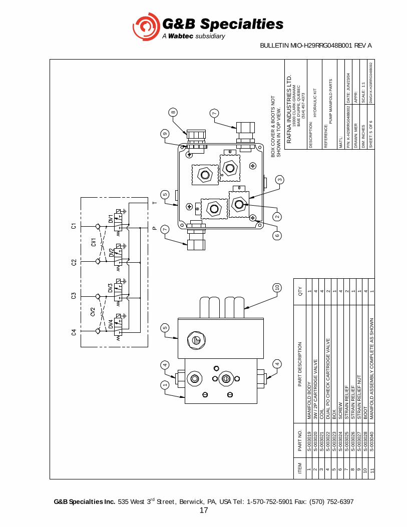
4.0 Parts Hydraulic Pump Components ............................................................... 16 Hydraulic Manifold Components ............................................................ 17 Control Box ..................................................................................... 18

BULLETIN MIO-H29RRG048B001 REV A
G&B Specialties Inc. 535 West 3rd Street, Berwick, PA, USA Tel: 1-570-752-5901 Fax: (570) 752-6397 4
1.0 INSTALLATION OF HYDRAULIC KIT
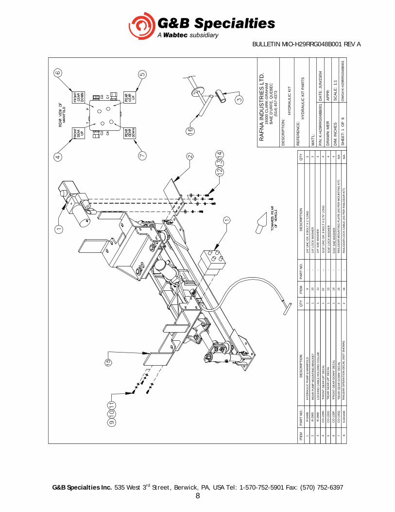
Table 1: Hydraulic Kit Installation Parts Part Number Description Qty
R-048B Hydraulic Pump And Manifold 1 R-2965 Rear Pump Mounting Bracket 1 R-1567 Dash Switch 1 R-1577 In-Line Fuse 5 Amp 1
CO-130G “Railgear Pump” Decal 1 CO-130N “Front Gear Up” Decal 1 CO-130O “Rear Gear Up” Decal 1 CO-130P “Front Gear Down” Decal 1 CO-130Q “Rear Gear Down” Decal 1 R-2868 Locking Cable Holding Collar 1
S-001030 Railgear Operation Decal 2 849FSO-04-04 ¼” Male O-Ring Boss to ¼” Male JIC 90° 7 849FSO-04-06 3/8” Male O-Ring Boss to ¼” Male JIC 90° 3
HFS2-04 Hose 23”Long 2 HFS2-04 Hose 33” Long 2 HFS2-04 Hose 360” Long 2
HU04-04NJ ¼” Female JIC Straight Coupler (On Hoses) 12
1/4” UNC Gr. 8 Bolt x 1” Long 3 1/4” SAE Washer 3 1/4” Lock Washer 3 5/16” UNC Gr. 8 Bolt x 0.75” Long 4 5/16” SAE Washer 4 5/16” Lock Washer 4
Not Supplied 2 & 14 Gauge Wire, Terminals, Loom, Etc. As Req’d 1. The pump is shipped with a manifold, a hand pump handle, a solenoid, and a rubber
terminal boot. 2. Locate and install the solenoid in a convenient location under the hood near the vehicle’s
battery using installer supplied hardware. Ensure that the solenoid’s body is electrically grounded.
3. Install all hydraulic fittings and adapters as shown on hydraulic schematic. 4. Position the rear pump mounting bracket against the right side rear mounting plate as
shown. Clamp it in place. Position the pump on top of the rear pump mounting bracket as shown with the tank towards the right side of the vehicle. Ensure the pump will not interfere with any part of the vehicle or railgear components. The hand pump handle receiver can be turned to point downwards to ease hand pump handle use.
BULLETIN MIO-H29RRG048B001 REV A
G&B Specialties Inc. 535 West 3rd Street, Berwick, PA, USA Tel: 1-570-752-5901 Fax: (570) 752-6397 5
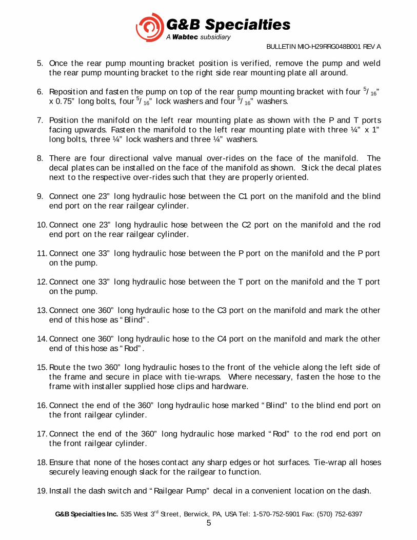
5. Once the rear pump mounting bracket position is verified, remove the pump and weld the rear pump mounting bracket to the right side rear mounting plate all around.
6. Reposition and fasten the pump on top of the rear pump mounting bracket with four 5/16”
x 0.75” long bolts, four 5/16” lock washers and four 5/16” washers. 7. Position the manifold on the left rear mounting plate as shown with the P and T ports
facing upwards. Fasten the manifold to the left rear mounting plate with three ¼” x 1” long bolts, three ¼” lock washers and three ¼” washers.
8. There are four directional valve manual over-rides on the face of the manifold. The
decal plates can be installed on the face of the manifold as shown. Stick the decal plates next to the respective over-rides such that they are properly oriented.
9. Connect one 23” long hydraulic hose between the C1 port on the manifold and the blind
end port on the rear railgear cylinder. 10. Connect one 23” long hydraulic hose between the C2 port on the manifold and the rod
end port on the rear railgear cylinder. 11. Connect one 33” long hydraulic hose between the P port on the manifold and the P port
on the pump. 12. Connect one 33” long hydraulic hose between the T port on the manifold and the T port
on the pump. 13. Connect one 360” long hydraulic hose to the C3 port on the manifold and mark the other
end of this hose as “Blind”. 14. Connect one 360” long hydraulic hose to the C4 port on the manifold and mark the other
end of this hose as “Rod”. 15. Route the two 360” long hydraulic hoses to the front of the vehicle along the left side of
the frame and secure in place with tie-wraps. Where necessary, fasten the hose to the frame with installer supplied hose clips and hardware.
16. Connect the end of the 360” long hydraulic hose marked “Blind” to the blind end port on
the front railgear cylinder. 17. Connect the end of the 360” long hydraulic hose marked “Rod” to the rod end port on
the front railgear cylinder. 18. Ensure that none of the hoses contact any sharp edges or hot surfaces. Tie-wrap all hoses
securely leaving enough slack for the railgear to function. 19. Install the dash switch and “Railgear Pump” decal in a convenient location on the dash.

BULLETIN MIO-H29RRG048B001 REV A
G&B Specialties Inc. 535 West 3rd Street, Berwick, PA, USA Tel: 1-570-752-5901 Fax: (570) 752-6397 6
20. The pump manifold has two wire harnesses and two wires connected to it:
a) One 3’ wire harness for the rear railgear with a control box on the end. b) One 35’ wire harness for the front railgear with a control box on the end. c) One white and one black wire each with ring terminals on the ends.
21. Using suitable 14 gauge wire, cable loom, connectors, solder and heat shrink tubing:
a) Lengthen the white wire if required, and connect it from the manifold to the switching terminal on the railgear pump solenoid previously mounted under the hood.
b) Lengthen the black wire if required, and connect it from the manifold through the firewall to the load terminal on the dash switch.
c) Connect another length of black wire from the power terminal on the dash switch through the firewall to the in-line fuse.
d) Connect another length of black wire from the in-line fuse to the power terminal on the solenoid.
e) Connect another wire from the ground terminal on the dash switch to a suitable ground location on the vehicle.
f) Ensure the manifold is properly grounded to the vehicle chassis by connecting a wire from the manifold to a suitable ground location on the vehicle. The railgear may not be properly grounded due to paint on the mounting plates or tar on the frame.
22. Using suitable 2 gauge wire, cable loom, connectors, solder and heat shrink tubing: a) Connect one wire from the vehicle’s battery to the power terminal on the railgear
pump solenoid. b) Connect another wire from the load terminal on the solenoid to the power terminal
on the pump motor. Use the supplied rubber boot to protect the pump power terminal from shorting out.
c) Ensure the pump motor base is properly grounded to the vehicle chassis by connecting a wire from the pump motor base to a suitable ground location on the vehicle. The railgear may not be properly grounded due to paint on the mounting plates or tar on the frame.
23. Route the 35’ wire harness from the pump along the frame to the front of the vehicle and
secure in place with tie-wraps. If necessary, the control box can be removed from and reinstalled on the wire harness to facilitate routing. Fabricate a bracket and mount the front railgear control box with installer-supplied hardware in a protected vertical position in a suitable location. Ensure the control box is within reach of the railgear locking cable handle.
24. Route the 3’ wire harness from the pump to the rear of the vehicle and secure in place
with tie-wraps. If necessary, the control box can be removed from and reinstalled on the wire harness to facilitate routing. Fabricate a bracket and mount the rear railgear control box with installer-supplied hardware in a protected vertical position in a suitable location. Ensure the control box is within reach of the railgear locking cable handle.
BULLETIN MIO-H29RRG048B001 REV A
G&B Specialties Inc. 535 West 3rd Street, Berwick, PA, USA Tel: 1-570-752-5901 Fax: (570) 752-6397 7
25. Ensure that the control boxes are mounted vertically so that the controls do not fill with water and freeze. They should also be mounted in a location protected from road spray etc.
26. Affix the supplied railgear operation decals in a suitable location adjacent to the front
and rear control boxes. 27. Ensure all wires and terminals are soldered, heat shrink sealed, enclosed in protective
cable loom and secured with tie-wraps. 28. Ensure all holes in the firewall are sealed and protected with a grommet. 29. Fill the hydraulic system and bleed the air out:
a) Fill the pump tank with ESSO Univis Extra (or equivalent) hydraulic fluid. b) Operate the front railgear up and down briefly to circulate the fluid and bleed the
system of air (refer to the Railgear Kit and Hydraulic Kit Operation, Service, and Parts manuals for operation instructions).
c) Refill the pump tank and repeat the above step until all air is removed from the front hydraulic system.
d) Operate the rear railgear up and down briefly to circulate the fluid and bleed the system of air (refer to the Railgear Kit and Hydraulic Kit Operation, Service, and Parts manuals for operation instructions).
e) Refill the pump tank and repeat the above step until all air is removed from the rear hydraulic system.
f) With both front and rear railgear locked in the road position, fill the pump tank to the full line.
30. Follow the Hydraulic System Relief Valve Setting procedure detailed in the Hydraulic Kit
Service section of this manual. 31. Test the fit of the locking cable holding collar on both the front and rear locking cables.
Ensure that the locking cable holding collar keeps the railgear locking pin fully disengaged. Grind the locking cable holding collar or adjust the locking cable handle on the cable to fit if necessary.
32. Test the operation of the controls and directional valve manual over-rides. Refer to the
operation procedure in the Railgear Kit manual and Hydraulic Kit Operation section of this manual.
33. Locate and store the hand pump handle and the locking cable holding collar in a secure
location in the vehicle cab.
*Ensure that the thermal overload wires are properly spliced/connected as shown* *It is recommended that a 200 amp fuse be installed to isolate the hydraulic pump from the vehicle electrical system as shown*
BULLETIN MIO-H29RRG048B001 REV A
G&B Specialties Inc. 535 West 3rd Street, Berwick, PA, USA Tel: 1-570-752-5901 Fax: (570) 752-6397 8
1
"FR
ON
T G
EA
R U
P"
DE
CA
LC
O-1
30
N
7
119 10
8
"FR
ON
T G
EA
R D
OW
N"
DE
CA
L
"RE
AR
GE
AR
UP
" D
EC
AL
1/4
" L
OC
K W
AS
HE
R
1/4
" U
NC
GR
. 8
BO
LT
X 1
" L
ON
G
RA
ILE
AR
OP
ER
AT
ION
DE
CA
L (N
OT
SH
OW
N)
"RE
AR
GE
AR
DO
WN
" D
EC
AL
--
S-0
01
030
CO
-13
0Q
CO
-13
0P
CO
-13
0O
33
2111
R-2
965
R-0
48
B
PA
RT
NO
.IT
EM 3 5 6421
HY
DR
AU
LIC
PU
MP
& M
AN
IFO
LD
RE
AR
PU
MP
MO
UN
TIN
G B
RA
CK
ET
DE
SC
RIP
TIO
NQ
TY
1 1M
AT
'L:
P/N
: K-H
29R
RG
048B
001
DR
AW
N: M
ER
DIM
: IN
CH
ES
SH
EE
T:
1 O
F 6
DW
G#
:K-H
29R
RG
048B
001
AP
PR
:
SC
AL
E:
1:1
DA
TE
: JU
N/2
3/0
4
RA
FN
A I
ND
US
TR
IES
LT
D.
RE
FE
RE
NC
E:
DE
SC
RIP
TIO
N:
193
00 C
LA
RK
-GR
AH
AM
BA
IE D
'UR
FE
, QU
EB
EC
(514
) 45
7-43
73
HY
DR
AU
LIC
KIT
HY
DR
AU
LIC
KIT
PA
RT
S
-1
/4"
SA
E W
AS
HE
R3
5/1
6"
UN
C G
R.
8 B
OL
T X
0.7
5"
LON
G-
12
-
1413
5/1
6"
SA
E W
AS
HE
R
5/1
6"
LO
CK
WA
SH
ER
--
4 44
-R
AIL
GE
AR
MO
UN
TIN
G P
LAT
E (
AS
PE
R M
OU
NT
ING
KIT
)N
/A
DE
SC
RIP
TIO
NIT
EM
PA
RT
NO
.Q
TY
R-2
868
LO
CK
ING
CA
BL
E H
OL
DIN
G C
OL
LAR
15 16-
RA
ILG
EA
R L
OC
K C
AB
LE
(A
S P
ER
RA
ILG
EA
R K
IT)
N/A
2

BULLETIN MIO-H29RRG048B001 REV A
G&B Specialties Inc. 535 West 3rd Street, Berwick, PA, USA Tel: 1-570-752-5901 Fax: (570) 752-6397 9

BULLETIN MIO-H29RRG048B001 REV A
G&B Specialties Inc. 535 West 3rd Street, Berwick, PA, USA Tel: 1-570-752-5901 Fax: (570) 752-6397 10

BULLETIN MIO-H29RRG048B001 REV A
G&B Specialties Inc. 535 West 3rd Street, Berwick, PA, USA Tel: 1-570-752-5901 Fax: (570) 752-6397 11
OPERATION AND SERVICE OF HYDRAULIC KIT (STD) STD Controls
SAFETY PRECAUTIONS
If any operating, service or parts problems are encountered, please call G&B Specialties, Inc. for technical assistance.
Failure to heed to any of the following warnings could result in severe bodily injury
and/or equipment damage. Read and understand this manual completely before attempting operation of the
railgear equipped vehicle. Operating instructions provided below only address the Rafna Industries railgear
equipment. Applicable railway company procedures and policies must be adhered to. Railway company rules governing rail travel must be observed at all times. Before performing any work under the vehicle or railgear, ensure the engine is turned
off and the parking brake is set. Ensure all body parts and loose clothing are clear of any moving parts of the railgear.
Be aware of all pinch points. Note that if the railgear is part way retracted or extended, opening the manifold
directional valve manual over-rides may cause the railgear to drop suddenly causing personal injury. Ensure all body parts are clear of the railgear if it should suddenly drop.
When operating the railgear using the emergency hand pump, ensure that the correct
manual valve over-ride is open for the desired railgear (front or rear) and desired direction of operation (raise or lower).
Do not use the emergency hand pump to raise and lower the railgear on a routine
basis. If the hydraulic pump or manifold should fail, have it repaired as soon as possible.
If the emergency hand pump has been used to raise or lower the railgear, ensure the
manifold directional valve manual over-rides are in the closed and locked position before starting road or rail travel.
Ensure the hydraulic pump has been de-energized before starting road or rail travel.
!

BULLETIN MIO-H29RRG048B001 REV A
G&B Specialties Inc. 535 West 3rd Street, Berwick, PA, USA Tel: 1-570-752-5901 Fax: (570) 752-6397 12
2.0 OPERATION OF HYDRAULIC KIT With the hydraulic kit installed on this vehicle, it may be operated as normal. Never operate the vehicle if the Gross Vehicle Weight Rating (GVWR), Gross Axle Weight Rating Front or Rear (GAWR), or the wheel or tire load ratings are exceeded. Refer to the Railgear Kit Operation, Service and Parts manual for information on the mechanical operation, service and parts of the railgear. Location And Operation Of The Standard Railgear Hydraulic System Controls: The railgear hydraulic system consists of a hydraulic pump and manifold, a front control box and a rear control box. 1. The railgear hydraulic pump must be energized prior to use by turning on the respective dash
switch. At this point the dash switch light should come on but the pump should not run and the railgear should not move until a control button is depressed.
2. The direction of the front or rear railgear movement is selected by pushing the “Up” or “Down”
button on the respective control box located near the railgear. At this point the pump should start and the railgear should move in the selected direction.
3. To stop the movement of the railgear, release the depressed button. 4. The pump must be de-energized after use by turning off the respective dash switch. At this point
the pump should not be able to run and the control buttons should be in-active.
LOCATION AND OPERATION OF THE HYDRAULIC PUMP EMERGENCY HAND PUMP: If the railgear hydraulic system should fail such that the railgear does not respond to depressing the buttons on the front and / or rear control boxes, then the emergency hand pump system may be used to place the vehicle on rail or remove the vehicle from rail. Follow the standard operation procedure (as detailed in the Railgear Kit Operation, Service and Parts Manual) except substitute the following steps when the procedure requires raising or lowering of the railgear. 1. Remove the hand pump handle from storage and insert the handle into the hand pump located on
the body of the hydraulic pump. 2. There are four manifold directional valves, one for each railgear function: “Front Gear Up”,
“Front Gear Down”, “Rear Gear Up”, and “Rear Gear Down”. The manual over-rides for these valves are located on the manifold under rubber boots. Only open one manifold directional valve over-ride at a time. To manually open a manifold directional valve over-ride, remove the rubber boot, push in and twist the knob allowing the knob to extend. To manually close a manifold directional valve over-ride, push the knob in, twist the knob to lock it in place and replace the rubber boot.
3. Select and open the manual over-ride for the respective railgear and desired direction of
movement.

BULLETIN MIO-H29RRG048B001 REV A
G&B Specialties Inc. 535 West 3rd Street, Berwick, PA, USA Tel: 1-570-752-5901 Fax: (570) 752-6397 13
4. Remove the locking cable holding collar from storage. It can be slipped in between the locking cable handle and the locking cable bulkhead fitting to hold the locking cable in the disengaged position.
5. Pump the emergency hand pump handle to move the railgear. It will require 30 to 50 full strokes
to fully raise or lower each railgear. 6. Close the manual over-ride. Ensure all manifold directional valve manual over-rides are closed
and locked in position. Replace all the rubber boots. 7. Remove and store the locking cable holding collar and the hand pump handle. 8. Ensure the railgear lock pins are fully engaged as required by the procedure.

BULLETIN MIO-H29RRG048B001 REV A
G&B Specialties Inc. 535 West 3rd Street, Berwick, PA, USA Tel: 1-570-752-5901 Fax: (570) 752-6397 14
3.0 SERVICE OF HYDRAULIC KIT The hydraulic kit must be serviced regularly to avoid damage to the equipment. The recommended oil for the railgear hydraulic system is ESSO Univis Extra or equivalent. In extremely cold weather areas/seasons, ESSO Univis J13 or equivalent may be used.
Table 1: Recommended Service Schedule
Service Required
Init
ial 10
0 km
(6
2 M
iles
) of
ro
ad a
nd/o
r ra
il us
e
Dai
ly
Wee
kly
Mon
thly
Inspect hydraulic kit fasteners (re-torque if required)
Inspect all hydraulic fittings and hoses for leaks and wear.
Check oil in hydraulic reservoir. (fill with railgear raised if req’d)
Check emergency hand pump and manifold over-ride operation HYDRAULIC SYSTEM RELIEF VALVE SETTING This system is equipped with one relief valve located on the railgear pump body next to the emergency hand pump. This relief valve protects the entire hydraulic system from over pressurization. The relief valve will require adjustment at installation and if ever there appears to be inadequate hydraulic pressure to operate the railgear. 1. Disconnect the hydraulic hose from the “P” port of the pump. 2. Install a hydraulic pressure gauge (up to 3000 PSI) between the disconnected hydraulic hose and
the pump port. The pressure gauge will indicate the relief valve setting when the pump is loaded.
3. Following the procedure in the Railgear Kit Operation, Service and Parts manual, raise the front
railgear completely and continue to raise the railgear so that the hydraulic cylinder creates a load on the pump by trying to “dead-head”. The pressure reading on the pressure gauge should climb to 1800 PSI.
4. If the pressure is not correct, release the railgear controls and adjust the relief valve on the
pump accordingly. Loosen the lock nut and turn the setscrew in to increase the pressure or out to decrease the pressure. Re-check the pressure.
5. Once the correct pressure on the pump relief valve is obtained, ensure the lock nut on the relief
valve is tightened. Release the pressure in the system and remove the pressure gauge. Re-connect all hydraulic hoses.
6. Ensure the railgear is properly raised as per the Railgear Kit Operation, Service and Parts manual.
BULLETIN MIO-H29RRG048B001 REV A
G&B Specialties Inc. 535 West 3rd Street, Berwick, PA, USA Tel: 1-570-752-5901 Fax: (570) 752-6397 15
Electrical System Troubleshooting The following basic test can be performed to check the integrity of the railgear electrical system. Should the railgear pump fail to operate, first check the fuse or the circuit breaker and all wiring for shorts. Then the following test can be performed to verify the integrity of the pump motor and pump solenoid. 1. Pump motor test:
a) Connect one end of a 2 gauge shunt wire to the pump motor power terminal and touch the other end to the battery positive terminal.
b) The pump motor should run upon touching the shunt wire. c) If the pump does not run, the pump is not properly grounded or the pump motor is defective. d) If the pump motor runs, test for a defective solenoid.
2. Solenoid test:
a) Connect one end of a 14 gauge shunt wire to the switching terminal on the solenoid and touch the other end to the battery positive terminal. If the pump does not operate the solenoid is not properly grounded or it is defective. If the pump operates, the problem lies with the fuse/circuit breaker, wiring and/or switches.
Should the pump start running immediately following turning on the respective dash switch, the following tests can be performed to help locate the problem. 1. Disconnect the wire from the switching terminal on the solenoid. If the pump continues to run,
then the solenoid is defective. 2. Check all wiring and switches for shorts and / or loose terminals.

BULLETIN MIO-H29RRG048B001 REV A
G&B Specialties Inc. 535 West 3rd Street, Berwick, PA, USA Tel: 1-570-752-5901 Fax: (570) 752-6397 16
4.0 Parts
10
124
1
17
211
P
5
M
713
14
P
1516
RE
TU
RN
TU
BE
RE
SE
RV
OIR
CLA
MP
SP
RIN
G R
ET
AIN
ER
SO
LEN
OID
(N
OT
SH
OW
N)
O-R
ING
(N
OT
SH
OW
N -
AT
HA
ND
PU
MP
MO
UN
T)
SA
E 0
4 O
-RIN
G P
LUG
BA
LL
FO
LLO
WE
R
S-0
030
161
6
1S
-00
3006
61
/8"
PIP
E P
LUG
(N
OT
SH
OW
N -
TA
NK
PL
UG
)
HA
ND
PU
MP
MO
UN
TIN
G S
CR
EW
S-0
030
09S
-00
3008
S-0
030
07
S-0
030
101
08 97H
AN
D P
UM
P B
OD
Y
PU
MP
HA
ND
LE
SA
E 0
6 O
-RIN
G P
LU
G
11 31
S-0
030
30S
-003
018
S-0
030
171
81
9
17
PA
RT
DE
SC
RIP
TIO
N
S-0
030
04S
-00
3003
S-0
030
02S
-00
3001
PA
RT
NO
.
S-0
030
05
2 43 5
ITE
M
1
M25
4 M
INI P
UM
PM
OT
OR
SU
CT
ION
ELB
OW
BR
EA
TH
ER
PLA
ST
IC R
ES
ER
VO
IR 6
.5"
LO
NG
QT
Y
1 11 11
S-0
030
13
PA
RT
NO
.
S-0
030
12S
-00
3011
S-0
030
14
S-0
030
15
12
14
13
15
ITE
M
11
BA
LL
SP
RIN
G1 2 11
PA
RT
DE
SC
RIP
TIO
N
1 11
1
QT
Y
1
22
24
23
21
20
S-0
030
31S
-003
032
S-0
030
33S
-003
034
S-0
030
35
11
/4"
UN
C S
HS
C S
CR
EW
X 1
.25
LON
G (
NO
T S
HO
WN
) 0
.056
CU
- IN
/RE
V M
ICR
O P
UM
P (
NO
T S
HO
WN
)1
/16
" X
2-1
/4"
X 2
.37
5" O
-RIN
G S
EA
L (N
OT
SH
OW
N)
11
INT
ER
ME
DIA
TE
SH
AF
T (
NO
T S
HO
WN
)T
ER
MIN
AL
BO
OT
(N
OT
SH
OW
N)
11
27
28
26
25
S-0
030
36S
-003
037
S-0
030
38S
-003
041
11
/16
" X
3"
X 3
.13
" O
-RIN
G S
EA
L (N
OT
SH
OW
N)
PU
MP
AS
SE
MB
LY C
OM
PLE
TE
AS
SH
OW
N1
1/1
6"
X 1
/2"
X 5
/8"
O-R
ING
SE
AL
(N
OT
SH
OW
N)
1/4
" D
OW
EL
L P
IN X
1.2
5" L
ON
G (
NO
T S
HO
WN
)11
S-0
030
05A
PLA
ST
IC R
ES
ER
VO
IR 1
1"
LON
GP
UM
P P
AR
TS
RA
FN
A IN
DU
ST
RIE
S L
TD
.
MA
T'L
:
SH
EE
T: 4
O
F 6
P/N
: K
-H29
RR
G04
8B00
2
DR
AW
N: M
ER
DIM
: IN
CH
ES
DW
G#:
K-H
29R
RG
048B
002
DA
TE
: JU
N/2
3/04
AP
PR
:
SC
ALE
: 1
:1
DE
SC
RIP
TIO
N:
193
00 C
LAR
K-G
RA
HA
MB
AIE
D'U
RF
E, Q
UE
BE
C(5
14)
457
-437
3
RE
FE
RE
NC
E:
HY
DR
AU
LIC
KIT
T
83
9
BULLETIN MIO-H29RRG048B001 REV A
G&B Specialties Inc. 535 West 3rd Street, Berwick, PA, USA Tel: 1-570-752-5901 Fax: (570) 752-6397 17
MA
NIF
OLD
BO
DY
ITE
M
1
PA
RT
NO
.
S-0
0301
9
QT
YP
AR
T D
ES
CR
IPT
ION
12
S-0
0302
03W
/ 2P
CA
RT
RID
GE
VA
LVE
43
S-0
0302
1C
OIL
44
S-0
0302
2D
UA
L P
O C
HE
CK
CA
RT
RID
GE
VA
LVE
25
S-0
0302
3B
OX
16
S-0
0302
4S
CR
EW
47
S-0
0302
5S
-003
026
S-0
0302
7S
-003
028
1098
ST
RA
IN R
ELI
EF
BO
OT
ST
RA
IN R
ELI
EF
ST
RA
IN R
ELI
EF
NU
T
2 41 1
4
BO
X C
OV
ER
& B
OO
TS
NO
T
SH
OW
N I
N T
OP
VIE
W.
55
9
8 7
32
104
17
6
RA
FN
A I
ND
US
TR
IES
LT
D.
MA
T'L
:
SH
EE
T: 5
OF
6
P/N
: K-H
29R
RG
048B
002
DR
AW
N: M
ER
DIM
: IN
CH
ES
DW
G#:
K-H
29R
RG
048B
002
DA
TE
: JU
N/2
3/04
AP
PR
:
SC
ALE
: 1:
1
DE
SC
RIP
TIO
N:
193
00 C
LAR
K-G
RA
HA
MB
AIE
D'U
RF
E, Q
UE
BE
C(5
14)
457
-437
3
RE
FE
RE
NC
E: P
UM
P M
AN
IFO
LD P
AR
TS
HY
DR
AU
LIC
KIT
11
S-0
0304
0M
AN
IFO
LD A
SS
EM
BLY
CO
MP
LET
E A
S S
HO
WN
1

BULLETIN MIO-H29RRG048B001 REV A
G&B Specialties Inc. 535 West 3rd Street, Berwick, PA, USA Tel: 1-570-752-5901 Fax: (570) 752-6397 18