installation of the kubota 40 amp alternator upgrade kit
TRANSCRIPT

Installation of the Kubota 40 Amp Alternator Upgrade Kit on a Kubota B7800/ B3030 Tractor
Objective: To help install the Kubota 40 amp alternator upgrade on a Kubota B7800 or the B3030 tractor by using the following instructions. This document was created due to the inadequate instructions that are included in the original kit. The install procedure is presented in a series of PowerPoint slides taking the reader through the process step-by-step.

Front & Left Side Panel Removal
• Remove left side panel and front grill
Pull straight back on panels so clips disengage from frame
Front panel is removed for easy access to remove Positive battery terminal connection. I had to remove the front panel to get a socket into the battery compartment. Also once done I placed a anti-corrosion felt pad onto the terminals.
Before Picture of Engine Compartment with Dyno & Bracket
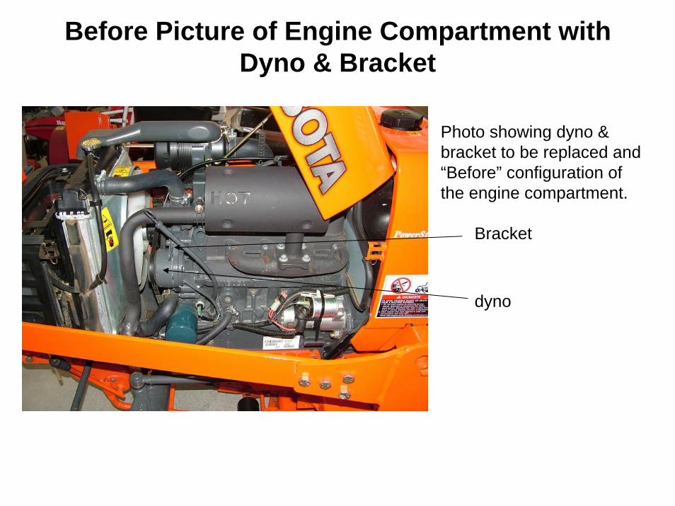
Photo showing dyno & bracket to be replaced and “Before” configuration of the engine compartment.
Bracket
dyno

Muffler Removal for Easy Access
Remove muffler by removing the four mounting nuts, removal of the entire muffler was easier than removing just the exhaust pipe, plus it gave me more access to work and I was able to put a nickel anti-seize compound on the studs when I was replacing the muffler.
Also note bend of the original oil dip stick. This will be reconfigured (re-bent) due to the new larger alternator, see later step below.

Remove Instrument Panel & Steering Wheel•Remove steering wheel by prying up on the center cap and removing nut from column.
•After steering wheel is removed, carefully pry up the instrumentation panel at the seem. Be careful not to deform the plastic, I used a small Craftsman flat blade screw driver starting at the back. Once a small separation was created I used my fingers to slowly pry the panel off. There are 5 clips that hold the panel onto the plastic shroud. See photo on next slide.
•Unscrew the tachometer cable from the back of the panel so that panel can be moved to the side as shown.
Clip locations to hold instrument panel to shroud. Two other clips on the right side not shown.

Remove Instrument Panel, Cont.
Start prying at this location with a small flat screw driver, followed by using your fingers to avoid damage to the plastic. Use care when lifting at clip locations

Removal of the Dyno & Old Bracket
•After all components are removed, remove dyno mounting bolts One on top (shown, one underneath not shown). (Photo is a “before” photo shown with muffler still in place).
•Remove bolts for dyno bracket (2)
•Save old bolts (painted gray).
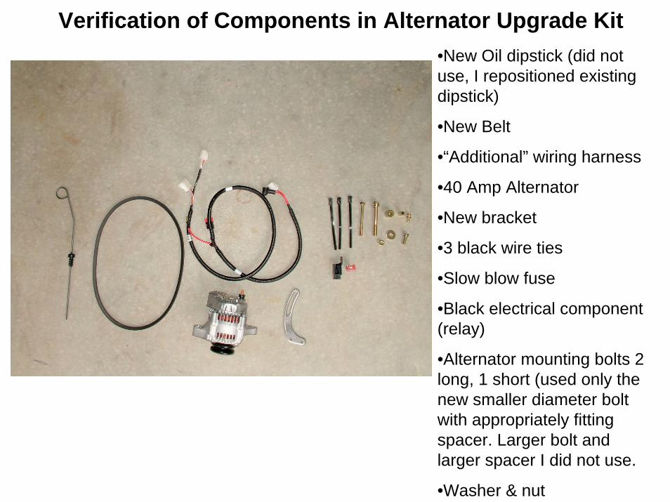
Verification of Components in Alternator Upgrade Kit•New Oil dipstick (did not use, I repositioned existing dipstick)
•New Belt
•“Additional” wiring harness
•40 Amp Alternator
•New bracket
•3 black wire ties
•Slow blow fuse
•Black electrical component (relay)
•Alternator mounting bolts 2 long, 1 short (used only the new smaller diameter bolt with appropriately fitting spacer. Larger bolt and larger spacer I did not use.
•Washer & nut

Verification of Components in Alternator Upgrade Kit
Larger bolt and spacer I did not use.
Smaller diameter bolt & spacer that I did use
40 Amp alternator

Attach New Alternator Bracket & Reposition Oil Dipstick Tube
•Attach the new bracket to the thermostat mount. Reuse the original gray painted bolts. Be certain to torque the bolts down to prevent seepage of coolant from housing. The bottom bolt also attaches the tachometer cable clip that prevents the cable from touching the fan pulley/ belt.
Mounting bolts with new bracket.
Carefully bend the original oil dipstick tube while the dipstick is installed. This must be done to prevent an interference between the tube and the new alternator. I was able to temporarily place the new alternator in place (by hand) and get an approximation of how much I needed to bend the tube. The tube must not touch any of the electrical connection on the back of the alternator.
Alternator & Belt Installation
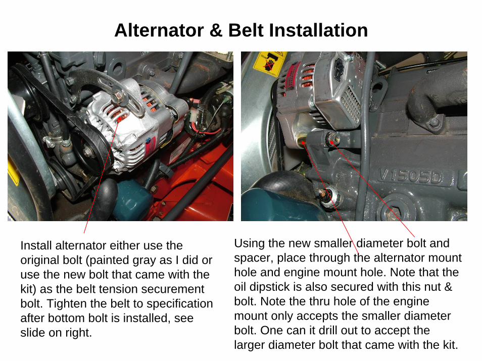
Install alternator either use the original bolt (painted gray as I did or use the new bolt that came with the kit) as the belt tension securement bolt. Tighten the belt to specification after bottom bolt is installed, see slide on right.
Using the new smaller diameter bolt and spacer, place through the alternator mount hole and engine mount hole. Note that the oil dipstick is also secured with this nut & bolt. Note the thru hole of the engine mount only accepts the smaller diameter bolt. One can it drill out to accept the larger diameter bolt that came with the kit.
Alternator Installation
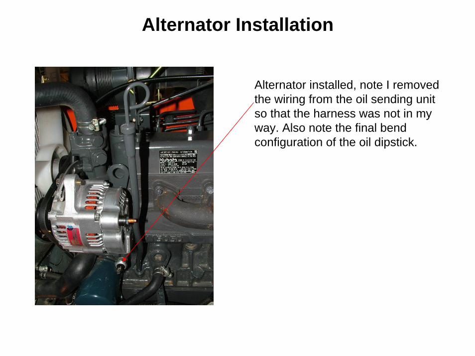
Alternator installed, note I removed the wiring from the oil sending unit so that the harness was not in my way. Also note the final bend configuration of the oil dipstick.

Remove Old Regulator
Remove old regulator from underneath the instrument panel. I used a 10mm flex socket due to the lack of room. Disconnect wiring harness from the regulator from plastic connector. Save old bolt for mounting the new relay, see next slide.

Removal of Old Regulator and Installation of New Relay
Install new wiring harness and connect the white plastic connector that mated up with the old regulator that you previously removed. This only has two wires, the regulator circuit is built into the new alternator, hence less wires. Also mount the new black relay on mount on bracket with a 10mm bolt that was used to mount the old regulator.
Install new wiring harness along side the existing harness. Feed harness through and underneath engine compartment “firewall”. Feed up to the instrument panel. Wire tie the new harness as shown.

Wiring Harness Installation
Place the new slow blow fuse into its housing and connect the new wiring harness to the starter making sure that the existing two wires from the original wiring harness are still attached. Cover the connector with the black rubber boot.
Connect the end of the wiring harness with the black boot to the copper terminal on the alternator and connect the white plastic connector to the appropriate male fitting on the back of the alternator.

Reassembly of Dismantled Components
• Reattach the tachometer cable to the instrument panel, followed by reassembly of the instrument panel. Use care as not scratch the instrument panel lens.
• Reattach the steering wheel, tighten the nut to specification.• Reinstall the muffler using the four nuts, use ant-seize
compound to aid with future removal and to minimize rust.• Replace battery cable and reinstall front and side panels.• Enjoy knowing that now your tractor has enough amperage to
replace or keep up with the draw due to your soon to be newly installed 100 watt driving & fog lights, 110 db horn, siren, and coffee maker.