installation, operating and maintenance … · iom - y-strainers, ... commissioning & operation...
TRANSCRIPT

IOM - Y-STRAINERS, UNIFLOW® F0-F9©
CO
ME
VAL
VALV
E S
YS
TEM
S T
echn
ical
Dep
t. R
ef. I
OM
- Y-
STR
AIN
ER
S, U
NIF
LOW
® F
0-F9
- E
d.18
/02
Com
eval
Val
ve S
yste
ms
rese
rves
the
right
to a
lter a
ny te
chni
cal d
ata
cont
aine
d in
this
Man
ual w
ithou
t prio
r not
ice.
Reg
ular
ly u
pdat
ed d
ata
on w
ww
.com
eval
.es
Page 1
INSTALLATION, OPERATINGAND MAINTENANCE MANUAL
Y-STRAINERSContents
UNIFLOW® F0-F9
1. GENERAL INFORMATION ON THE MANUAL ..............22. NOTES ON POSSIBLE DANGERS ................................22.1Significanceofsymbols ..............................................22.2 Explanatory notes on safety information .....................2
3. PRESERVATION, STORAGE, HANDLING AND TRANSPORT ......................................................................24. DESCRIPTION ................................................................2
4.1 General Description. Area of Application. Operating principles ...........................................................................24.2 Technical data - remarks .............................................24.3 Marking/nameplate .....................................................34.4 CE marking .................................................................3
5. INSTALLATION ...............................................................35.1 General remarks on installation ..................................35.2 Requirements at the place of installation ....................4
6. COMMISSIONING & OPERATION .................................47. CARE AND MAINTENANCE ..........................................58. TROUBLESHOOTING ....................................................59. TROUBLESHOOTING TABLE .......................................510. DISMANTLING THE STRAINER ..................................511. GOODS RETURN & DISPOSAL .................................612. WARRANTY / GUARANTEE ........................................613. PARTS LIST ..................................................................614. ANNEXES .....................................................................6
14.1 Declaration of Conformity .........................................614.2 Data Sheet ................................................................6
IOM - Y-STRAINERS, UNIFLOW® F0-F9©
CO
ME
VAL
VALV
E S
YS
TEM
S T
echn
ical
Dep
t. R
ef. I
OM
- Y-
STR
AIN
ER
S, U
NIF
LOW
® F
0-F9
- E
d.18
/02
Com
eval
Val
ve S
yste
ms
rese
rves
the
right
to a
lter a
ny te
chni
cal d
ata
cont
aine
d in
this
Man
ual w
ithou
t prio
r not
ice.
Reg
ular
ly u
pdat
ed d
ata
on w
ww
.com
eval
.es
Page 2
1. GENERAL INFORMATION ON THE MANUAL-ThisManualprovidesinformationonsafelyusingtheproduct,beingbindingforpreservation,storage,handling,transport,installation,commissioning,operation,maintenance,repairanddisposal,andmustbethoroughlyobservedatanystep.-PleasecontactthesupplierorthemanufacturerincaseofissueswhichcannotbesolvedbyreferencetothisManual.-AnydeviationfromthisManualandsoundengineeringpracticeormodificationontheproductshallbenotifiedtomanu-facturer for advice or approval.-Inaddition,regionalsafetyrequirementsmustbealwaysappliedandobservedatanystep.-Alltheworkrelatedtotheproductmustbecarriedout,supervisedandinspectedbyspecialistpersonnel.Itistheowner’sresponsibilitytodefineareasofresponsibilityandcompetenceandtoensurethepropermonitoring.- This Manual is in accordance with Directive 2014/68/EU on Pressure Equipment (PED).- IncaseofcompliancewithATEXDirective2014/34/EU,pleaseobservealsoadditionalATEXspecificInstructions.-Themanufacturerreservestherighttomaketechnicalmodificationsatanytime.
2. NOTES ON POSSIBLE DANGERS2.1Significanceofsymbols
ATTENTION! ...
Warning of general danger.
2.2ExplanatorynotesonsafetyinformationIn this Manual dangers, risks and items of safety information are highlighted to attract special attention.Informationmarkedwiththesymbolabovedescribespractices,whichiffailtocomplywith,canresultinseriousinjuryordanger of death for users or third parties or in material damage to the system or the environment. It is vital to comply with these practices and to monitor compliance.TherestofinformationnotspecificallyemphasizedinthisManual,alongwithDataSheetandproductmarking,mustalsobeobservedandcompliedwithforsafelyusingtheproduct.
3. PRESERVATION, STORAGE, HANDLING AND TRANSPORT
ATTENTION!
- Protect against external force (impacts, vibrations, etc.).- Allow only skilled personnel; suitable handling and lifting equipment must be used. See Data Sheet for weights or consult manufacturer.- Always use suitable protection equipment, and minimize the use of human body force at any step to avoid injuries.- There is a risk of body member (hand, finger, arm…) crushed against any other solid element (wall, pipe, floor, etc.) during handling. Take this into account and handle with care.- Check correct position of nameplate and handle with care to avoid personnel cuttings.
- Use proper packing for transportation.-Keepstorageprotectionbeforeinstallation.- Use proper packing for transportation.-Keepstorageprotectionbeforeinstallation.- In order to prevent damage, corrosion or rust on the surface, avoid extreme temperatures (keep at 5ºC to 50ºC), avoid highenvironmentalhumidityorcorrosiveenvironment.Keepthestrainersawayfromdirectsunlight,dust,flamesorrain.Donotpileupexcessiveweight.Incaseofseverebumpinginspectthematerialforanydamageandreplaceifnecessary.
4. DESCRIPTION4.1GeneralDescription.AreaofApplication.OperatingprinciplesY-Strainersseriesaredevicesformechanicallyremovingsolidsfromflowingmediabymeansofawiringmeshorperfo-ratedbasket(screen),cleanableandreplaceableinline.Theyareusedtoprotectfromdirtorimpuritiesotherequipmentssuch as valves, pumps and other pipeline accessories. StrainersdiagramswithpartscanbeseenatthelastpageoftheManual.
4.2Technicaldata-remarksCheckproductselection,materialcompatibility,pressureandtemperaturelimitsandotheressentialparameters.Ensureproper safety devices/measures are implemented to prevent exceeding intended use of the product. Contact the manufac-turer for advice in case of pressure tests exceeding the intended use. Refer to Data Sheet for data such as main features, duties/limits of use, dimensions, weights, etc and consult the manufacturer for further information.
IOM - Y-STRAINERS, UNIFLOW® F0-F9©
CO
ME
VAL
VALV
E S
YS
TEM
S T
echn
ical
Dep
t. R
ef. I
OM
- Y-
STR
AIN
ER
S, U
NIF
LOW
® F
0-F9
- E
d.18
/02
Com
eval
Val
ve S
yste
ms
rese
rves
the
right
to a
lter a
ny te
chni
cal d
ata
cont
aine
d in
this
Man
ual w
ithou
t prio
r not
ice.
Reg
ular
ly u
pdat
ed d
ata
on w
ww
.com
eval
.es
Page 3
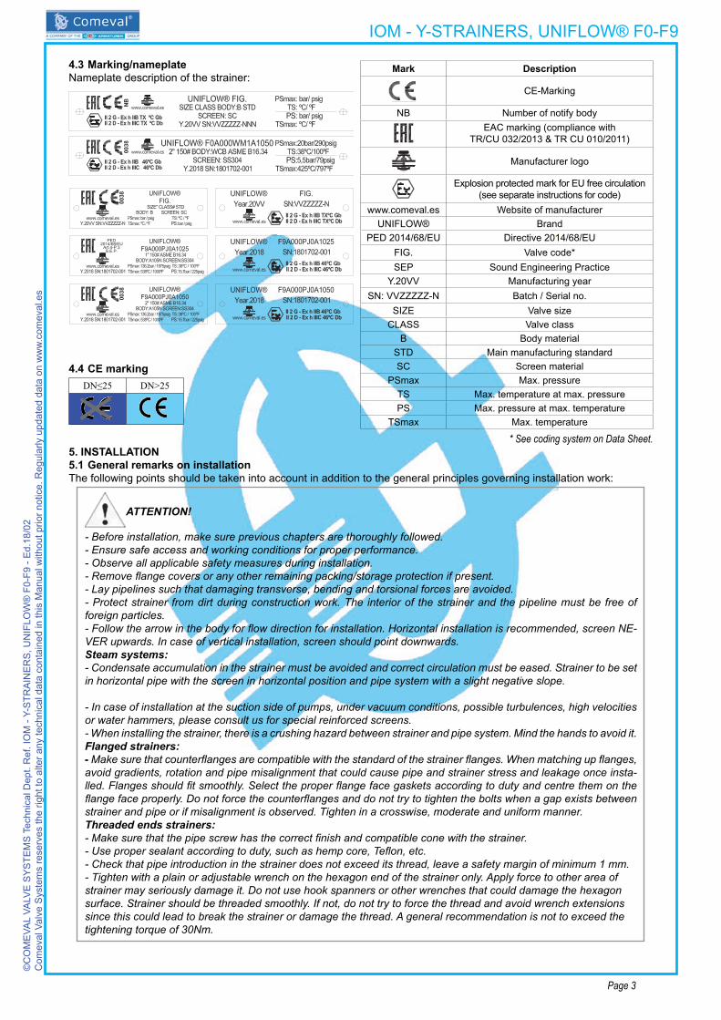
4.3Marking/nameplateNameplate description of the strainer:
Mark Description
CE-Marking
NB NumberofnotifybodyEAC marking (compliance with
TR/CU 032/2013 & TR CU 010/2011)
Manufacturer logo
Explosion protected mark for EU free circulation (see separate instructions for code)
www.comeval.es WebsiteofmanufacturerUNIFLOW® Brand
PED 2014/68/EU Directive 2014/68/EUFIG. Valve code* SEP Sound Engineering Practice
Y.20VV Manufacturing yearSN: VVZZZZZ-N Batch / Serial no.
SIZE ValvesizeCLASS Valve class
B Body materialSTD Main manufacturing standardSC Screen material
PSmax Max. pressureTS Max. temperature at max. pressurePS Max. pressure at max. temperature
TSmax Max. temperature
4.4CEmarkingDN≤25 DN>25
* See coding system on Data Sheet.5. INSTALLATION5.1GeneralremarksoninstallationThefollowingpointsshouldbetakenintoaccountinadditiontothegeneralprinciplesgoverninginstallationwork:
ATTENTION!
- Before installation, make sure previous chapters are thoroughly followed. - Ensure safe access and working conditions for proper performance.- Observe all applicable safety measures during installation.- Remove flange covers or any other remaining packing/storage protection if present.- Lay pipelines such that damaging transverse, bending and torsional forces are avoided.- Protect strainer from dirt during construction work. The interior of the strainer and the pipeline must be free of foreign particles.- Follow the arrow in the body for flow direction for installation. Horizontal installation is recommended, screen NE-VER upwards. In case of vertical installation, screen should point downwards. Steam systems: - Condensate accumulation in the strainer must be avoided and correct circulation must be eased. Strainer to be set in horizontal pipe with the screen in horizontal position and pipe system with a slight negative slope.
- In case of installation at the suction side of pumps, under vacuum conditions, possible turbulences, high velocities or water hammers, please consult us for special reinforced screens.- When installing the strainer, there is a crushing hazard between strainer and pipe system. Mind the hands to avoid it. Flanged strainers:-Make sure that counterflanges are compatible with the standard of the strainer flanges. When matching up flanges, avoid gradients, rotation and pipe misalignment that could cause pipe and strainer stress and leakage once insta-lled. Flanges should fit smoothly. Select the proper flange face gaskets according to duty and centre them on the flange face properly. Do not force the counterflanges and do not try to tighten the bolts when a gap exists between strainer and pipe or if misalignment is observed. Tighten in a crosswise, moderate and uniform manner.Threaded ends strainers:- Make sure that the pipe screw has the correct finish and compatible cone with the strainer. - Use proper sealant according to duty, such as hemp core, Teflon, etc.- Check that pipe introduction in the strainer does not exceed its thread, leave a safety margin of minimum 1 mm.- Tighten with a plain or adjustable wrench on the hexagon end of the strainer only. Apply force to other area of strainer may seriously damage it. Do not use hook spanners or other wrenches that could damage the hexagon surface. Strainer should be threaded smoothly. If not, do not try to force the thread and avoid wrench extensions since this could lead to break the strainer or damage the thread. A general recommendation is not to exceed the tightening torque of 30Nm.

IOM - Y-STRAINERS, UNIFLOW® F0-F9©
CO
ME
VAL
VALV
E S
YS
TEM
S T
echn
ical
Dep
t. R
ef. I
OM
- Y-
STR
AIN
ER
S, U
NIF
LOW
® F
0-F9
- E
d.18
/02
Com
eval
Val
ve S
yste
ms
rese
rves
the
right
to a
lter a
ny te
chni
cal d
ata
cont
aine
d in
this
Man
ual w
ithou
t prio
r not
ice.
Reg
ular
ly u
pdat
ed d
ata
on w
ww
.com
eval
.es
Page 4
ATTENTION!
WeldIing ends strainers:- Welding works must be carried out in accordance with approved procedure and following appropriate safety measures. Check correct pipe alignment. Clean strainer and pipe connections carefully, tack-weld each end of the strainer on to the pipe in 4 or more points depending on size and weight. Take the necessary precautions to prevent thermal stressing/overheating of the strainer.- In case of PWHT, temperature, gradient and time exposure should be controlled to the minimum required depen-ding on the material. PWHT should be applied firstly to one end and secondly to the other end (not simultaneously), and only to a limited area of each end of the strainer, in order to limit the temperature exposure on the welding area, and rest of the strainer body. An appropriate method is the use of ceramic blankets covering the length of the wel-ding area plus a minimum additional length that is determined by the standard of the pipe, being the heating zone limited to the minimum necessary as mentioned before. Electrical resistances must be set carefully in order to allow uniform heating and avoid too hot points. Permanent control and register of the temperature should be carried out during the process in order not to exceed the established temperature/time cycle. Also the adjacent areas should be monitored to control reached temperatures.
5.2Requirementsattheplaceofinstallation- Aggressive environmental conditions may reduce the life span of the product. Consider special construction/protective measures in such a case.-Consider the interactionbetweenthesystemandtheequipment.Foreseeelements toabsorbvibrations,pipedilata-tions, guides, anchoring and proper support according to the weight of the components.-Thesystemandoperationprotocolshouldbeconceivedinsuchawaytoavoidhighvelocities.Preventpulsingfloworwater hammers, which are very harmful for strainers and the rest of the components.- Flooding of the product is not recommended.- Allow enough space for strainer installation, operation and maintenance.
-Planners/constructioncompaniesortheownerareresponsibleforpositioningandinstallingproducts.
6. COMMISSIONING & OPERATION
ATTENTION!
- Before commissioning the strainer, check the material, pressure, temperature, flow direction and other essential parameters. Always use the product within the scope of intended service and operating duties.- Before commissioning, make sure previous chapters have been thoroughly followed.- Regional safety instructions should be adhered to.- It is essential to flush the pipe system thoroughly to eliminate all the particles and impurities which could remain in the pipes and particularly welding residue, chips, tool remains, etc. that could damage the equipment during start- up. Ensure that during cleaning of the pipe system, any chemicals used and temperature are compatible with the strainer construction.- Temperatures above 50ºC or below 0ºC may cause personnel injuries if strainers are touched.- Leakage of media through strainer or connections may also cause scalding, health harm, pollution, fire or damage to other parts of the installation depending on the media. Use suitable protection equipment when approaching the strainer, ensure that the corresponding warning signs are displayed on the strainer or surrounding area, and/or isolate the equipment in case of danger.- Before commissioning a new plant or restarting it after repairs or modification, always ensure that:
- All work has been completed correctly.- The strainer is in the correct position for its function.- Safety devices/measures have been implemented.
- Strainer operation, filling, warming-up and starting-up shall be gradual so as to avoid any inadmissible stress. Check for tightness in strainer connections and body/cover union, and retighten crosswise and gradually if neces-sary until leakage elimination.
- Ensure strainer surface is in good condition and retouch coating protection if any when needed.-Incaseofriskofmediafreezinginsidethestrainer,takeduemeasurestoavoidit.

IOM - Y-STRAINERS, UNIFLOW® F0-F9©
CO
ME
VAL
VALV
E S
YS
TEM
S T
echn
ical
Dep
t. R
ef. I
OM
- Y-
STR
AIN
ER
S, U
NIF
LOW
® F
0-F9
- E
d.18
/02
Com
eval
Val
ve S
yste
ms
rese
rves
the
right
to a
lter a
ny te
chni
cal d
ata
cont
aine
d in
this
Man
ual w
ithou
t prio
r not
ice.
Reg
ular
ly u
pdat
ed d
ata
on w
ww
.com
eval
.es
Page 5
7. CARE AND MAINTENANCETheoperatormustdefinemaintenanceandmaintenance-intervalstomeetrequirements.-Checkforbodyandconnectionstightness.
ATTENTION!
- Before disassembling the strainer, note chapters 3, 10 & 12.- Only carry out maintenance work in the pipework when the strainer has been secured from operation.- Check the strainer surface inside and outside and retouch coating protection if any when needed. If advanced corrosion or erosion is observed, double check service and strainer features and replace the strainer properly.
- If there is leakage through unions, refer to chapters 5 & 6.-Dependingonthedegreeofdirtaccumulation in thesystem,thescreenmustbecleanedafteraspecificnumberofservicehours.Strainer’sscreenmustbeextractedandcleanedwhencloggingbecomesapparent.Screencanbeeasilyextractedbyremovingcoverafterlooseningcoverbolting.- Once the screen is cleaned with compressed air or another method, clean gasket seat surface and insert a new gasket. Thentightenthecoverboltingevenlycrosswisewithuniformtorque.After any maintenance work please refer to chapters 5 and 6 for installation / commissioning.
RecommendedSpareparts:Use only original spare parts.Typeandnumberofeachspareparttobestoredaccordingtomanyfactors:servicelevel,strainersquantity,etc.Asageneral recommendation: 1 spare screen and 4 gaskets for 2 years operation.
8. TROUBLESHOOTINGIn theeventofmalfunctionor faultyoperatingperformance,check that the installationandadjustmentworkhasbeencarried out and completed in accordance with this Manual.
ATTENTION!
- It is essential that the safety regulations are observed when identifying faults.
9. TROUBLESHOOTING TABLE
ATTENTION!
- Read the complete Manual before carrying out installation and repair work.- Read chapter 6 before recommissioning.
FAULT POSSIBLE CAUSE CORRECTING MEASURESNoflowNotenoughflow
Flange covers not removed RemoveflangecoversStrainer clogged Clean/replace screenPiping clogged Check piping system
Brokenflange Bolts not properly tightened Re-alignpipingandfitnewstrainerMatingflangesnotproperlyaligned
Screen deformed or damaged
Vacuum conditions Check the system and install a special reinforced screenClean the screen often to avoid clogging of the system
Installation at suction side of a pumpTurbulencesHigh velocityWater hammer
Leakagebetweenbodyandcover Coverboltingloosenedorgasketdamaged Retighten or change gasket
Technicalsupportalwaysavailablethroughourwebsitewww.comeval.esoryourlocaldistributor.
10. DISMANTLING THE STRAINER
ATTENTION!
The following points must be observed:- Pressureless pipe system.- Medium must be cool.- Plant must be drained.- Note chapter 3 for proper handling and lifting.- Additionally, in case of toxic, corrosive, flammable or caustic media:
- Purge pipe system carefully.- Use proper protection equipment to avoid health harm.- Adopt proper actions to avoid pollution of the environment.

IOM - Y-STRAINERS, UNIFLOW® F0-F9©
CO
ME
VAL
VALV
E S
YS
TEM
S T
echn
ical
Dep
t. R
ef. I
OM
- Y-
STR
AIN
ER
S, U
NIF
LOW
® F
0-F9
- E
d.18
/02
Com
eval
Val
ve S
yste
ms
rese
rves
the
right
to a
lter a
ny te
chni
cal d
ata
cont
aine
d in
this
Man
ual w
ithou
t prio
r not
ice.
Reg
ular
ly u
pdat
ed d
ata
on w
ww
.com
eval
.es
Page 6
11. GOODS RETURN & DISPOSAL -Foranyreturnedgoods,theissuingcompanymustprovideinformationinwrittenonanyhazardsandtheprecautionincase of potentially polluting or harmful residues, or any mechanical damage that could present a health, safety or environ-mentalrisk,asenforcedbyEUHealth,SafetyandEnvironmentLaw,includingtheSafetyDataSheetofthesubstancesidentifiedaspotentiallyhazardous.-Strainersarerecyclableandnotexpectedhazardtotheenvironment,withtheexceptionofsoftparts(PTFEandrubbercompounds)thatshouldbedisposedseparatelyonlybyapprovedprocedure,andnoincinerationispermitted.
12. WARRANTY / GUARANTEE-Theextentandperiodofwarrantycoverarespecifiedinthe“GeneralSalesTerms”ofCOMEVALVALVESYSTEMSvalidatthetimeofdeliveryor,bywayofdeparture,inthecontractofsaleitself.-Weguaranteefreedomoffaultsincompliancewithstate-of-the-arttechnologyandtheconfirmedapplication.- No warranty claims are accepted for any damage caused as the result of incorrect handling or disregard of this Manual, Data Sheet and relevant regulations.- This warranty also does not cover any damage which occurs during operation under conditions deviating from those laid downbyspecificationsorotheragreements.-Justifiedcomplaintswillbeeliminatedbyrepaircarriedoutbyusorbyaspecialistappointedbyus.-Noclaimswillbeacceptedbeyondthescopeofthiswarranty.Therighttoreplacementdeliveryisexcluded.- The warranty shall not cover maintenance work. - Our guarantee coverage does not cover for any commissioning, maintenance or installation of the product or external parts.-Ourguaranteedoesnotcoverproductsprovedtohavebeentamperedwithorfaultedbymaterialwearandtear.-ThePurchaserisresponsibleforcheckingthattheincomingproductisreceivedingoodconditionandconformstotheorderedspecifications.Incaseofdamagecausedduringtransititisnecessarytoimmediatelycomplaintothecarrierwithin24hours.Afterthistimecarrierscouldnotassumethederivedcosts.Incaseofanydeviationinrelationtoorderspecifi-cations, please contact us.
13. PARTS LIST
Nº PART01 Body02 Cover03 Gasket04 Drain plug05 Coverbolt06 Cover nut07 Screen
14. ANNEXES14.1DeclarationofConformity-DC20_15EN14.2DataSheet-DS20 Updated documents on www.comeval.es
COMEVALVALVESYSTEMS,S.L.yCIA.,Soc.ComanditariaLes Rotes, 15 46540 El Puig (Valencia) EspañaPhone+34 961 479 011 · Fax+34 961 472 [email protected] - www.comeval.es