installation, operating and service instructions advantage ... · installation, operating and...
TRANSCRIPT

INSTALLATION, OPERATING AND SERVICE INSTRUCTIONS
ADVANTAGE™ SERIES CAST IRON OIL-FIRED BOILER
104105-05 - 8/14
9700609
For service or repairs to boiler, call your heating contractor. When seeking information on boiler, provide Boiler Model Number and Serial Number as shown on Rating Label.
Boiler Model Number
AO _Boiler Serial Number Installation Date
Heating Contractor Phone Number
Address

2
IMPORTANT INFORMATION - PLEASE READ THIS PAGE CAREFULLY
1. Read and understand all instructions, including all those contained in component manufacturers manuals which are provided with the appliance before installing, starting-up, operating, maintaining or servicing this appliance. Keep this manual and literature in legible condition and posted near appliance for reference by owner and service technician.
2. All heating systems should be designed by competent contractors and only persons knowledgeable in the layout and installation of hydronic heating systems should attempt installation of any boiler.
3. All boilers must be installed in accordance with National, State and Local Plumbing, Heating and Electrical Codes and the regulations of the serving utilities. These Codes and Regulations may differ from this instruction manual. Authorities having jurisdiction should be consulted before installations are made.
In all cases, reference should be made to the following Standards:
USA BOILERS
A. Current Edition of American National Standard ANSI/NFPA 31, “Installation of Oil Burning Equipment”, for recommended installation practices.
B. Current Edition of American National Standard ANSI/NFPA 211, “Chimneys, Fireplaces, Vents, and Solid Fuel Burning Appliances”, For Venting requirements.
C. Current Edition of American Society of Mechanical Engineers ASME CSD-1, “Controls and Safety Devices for Automatically Fired Boilers”, for assembly and operations of controls and safety devices.
D. All wiring on boilers installed in the USA shall be made in accordance with the National Electrical Code and/or Local Regulations.
DANGERDO NOT store or use gasoline or other flammable vapors or liquids in the vicinity of this or any other appliance.
IMPORTANT
This boiler is equipped with a feature that saves energy by reducing the boiler water temperature as the heating load decreases. This feature is equipped with an override which is provided primarily to prevent the use of an external energy management system that serves the same function. THIS OVERRIDE MUST NOT BE USED UNLESS AT LEAST ONE OF THE FOLLOWING CONDITIONS IS TRUE: •Anexternalenergymanagementsystemisinstalledthatreducestheboilerwater temperature as the heating load decreases. •Thisboilerisnotusedforanyspaceheating. •Thisboilerispartofamodularormultipleboilersystemhavingatotalinputof 300,000 BTU/HR or greater. •Thisboilerisequippedwithatanklesscoil.

3
WARNINGThis boiler is suitable for installation on combustible flooring. Do not install boiler on carpeting.
Installation is not complete unless a pressure relief valve is installed into the tapping located on top left corner of rear section - See Piping and Trim Sections of this manual for details.
This boiler is designed to burn No. 2 fuel oil only. Do not use gasoline, crankcase drainings, or any oil containing gasoline. Never burn garbage or paper in this boiler. Do not convert to any solid fuel (i.e. wood, coal). Do not convert to any gaseous fuel (i.e. natural gas, LP). All flammable debris, rags, paper, wood scraps, etc., should be kept clear of the boiler at all times. Keep the boiler area clean and free of fire hazards.This boiler needs fresh air for safe operation and must be installed so there are provisions for adequate combustion and ventilation air.This boiler must be connected to an approved chimney in good condition. Serious property damage could result if the boiler is connected to a dirty or inadequate chimney. The interior of the chimney flue must be inspected and cleaned before the start of the heating season for any obstructions. A clean and unobstructed chimney flue is necessary to allow noxious fumes that could cause injury or loss of life to vent safely and will contribute toward maintaining the boiler's efficiency.Inspect flueways at least once a year - preferably at the start of the heating season. The inside of the combustion chamber, the vent system and boiler flueways should be cleaned if soot or scale has accumulated.When cleaning this boiler, do not damage combustion chamber liner and/or rear target wall. If damaged, combustion chamber insulation must be replaced immediately.This boiler requires regular maintenance and service to operate safely. Follow the instructions contained in this manual. Installation, maintenance, and service must be performed only by an experienced, skilled and knowledgeable installer or service agency.It is the responsibility of the installing contractor to see that all controls are correctly installed and are operating properly when the installation is completed. Do not tamper with or alter the boiler or controls.Do not operate unit if any control, switch, component, or device has been subject to water.Oil Burner and Controls must be checked at least once a year or as may be necessitated.All boilers equipped with burner swing door have a potential hazard which if ignored can cause severe property damage, personal injury or loss of life. Before opening swing door, turn off service switch to boiler to prevent accidental firing of burner outside the combustion chamber. Be sure to tighten swing door fastener completely when service is completed.Appliance materials of construction, products of combustion and the fuel contain alumina, silica, heavy metals, carbon monoxide, nitrogen oxides, aldehydes and/or other toxic or harmful substances which can cause death or serious injury and which are known to the state of California to cause cancer, birth defects and other reproductive harm. Always use proper safety clothing, respirators and equipment when servicing or working nearby the appliance.High water temperatures increase the risk of scalding injury. If this boiler is equipped with a tankless heater for domestic water supply, a flow regulator and automatic mixing valve must be installed properly in tankless heater piping. See Piping and Trim Sections of the manual for details.

4
I. General Information
A. INSPECT SHIPMENT carefully for any signs of damage.
1. ALL EQUIPMENT is carefully manufactured, inspected and packed. Our responsibility ceases upon delivery of crated boiler to the carrier in good condition.
2. ANY CLAIMS for damage or shortage in shipment mustbefiledimmediatelyagainstthecarrierbythe consignee. No claims for variances from, or shortage in orders, will be allowed by the manufacturer unless presented within sixty (60) days after receipt of goods.
B. LOCATEBOILERinfrontoffinalpositionbeforeremoving crate. See Figure 1.1. LOCATE so that smoke pipe connection
to chimney will be short and direct. BOILER IS SUITABLE FOR INSTALLATION ON COMBUSTIBLE FLOOR. Boiler cannot be installed on carpeting.
2. FOR BASEMENT INSTALLATION, provide a solidbase,suchasaconcretepad,iffloorisnotlevel,orifwatermaybeencounteredonflooraround boiler.
3. PROVIDE SERVICE CLEARANCE of at least 24”ontopofboilerforcleaningflueways.Provideat least 24” clearance from front jacket panel for servicing.
4. For minimum clearances to combustible materials. See Figure 2.
C. PROVIDE AIR SUPPLY AND VENTILATION to accommodate proper combustion. If natural ventilation is inadequate, provide a screened opening or duct from the boiler room to the outside. The opening or duct must be sized so the boiler input will not exceed 4,000 BTUH/Sq. In. of free area. If other air consuming appliances are near the boiler, the air inlet should be larger. Consult respective manufacturers.
Table of Contents
I. General Information .................................... 4
II. Installation Instructions .............................. 7
III. Indirect Water Heater Piping .................... 14
IV. Operating & Service Instructions ............ 15
V. Maintenance & Service Instructions. ...... 18
VI. Boiler Cleaning .......................................20
VII. Repair Parts ............................................22
VIII. Appendix Burner Specifications ...........................26

5
Figu
re 1
: A
O(T
)-3 T
hru
AO
(T)-5
Wat
er B
oile
r

6
Figure 2: Minimum Installation Clearances To Combustible Materials (Inches)
TABLE 1: DIMENSIONAL DATA (SEE FIGuRE 1)
TABLE 2: RATING DATA
NOTE 1: Listed clearances comply with American National Standard NFPA 31, Standard for the Installation of Oil Burning Equipment.
NOTE 2: Advantage™ Series boilers can be installed in rooms with clearances from combustible material as listed above. Listed clearances cannot be reduced for alcove or closet installations.
NOTE 3: For reduced clearances to combustible material, protection must be provided as described in the ANSI/NFPA 31 standard.
CA
AboveB
FrontChimney
ConnectorD
RearE
Sides6 24 18 6 6
Boiler Model
DimensionsApprox. Water Content
(Gallons)
Heat Transfer Surface Area
(Sq. Ft.)
Approx. Shipping Weight (LBS.)
"A" "B" "C"
AO(T)-3 17-3/8" 8-1/4" 5-7/8" 16 14.33 560AO(T)-4 22-3/8" 10-7/8" 6-7/8" 20 20.90 680AO(T)-5 27-3/8" 13-3/8" 7-7/8" 24 27.46 800
Maximum Working Pressure - Water: 50 PSIBoilers are shipped with a 30 PSI relief valve.
BoilerModel No.
Burner Capacity DOE Heating
Capacity(MBH)
NET AHRIWater Ratings
(MBH)
Minimum Chimney RequirementsAFUE
%GPH MBH Round
In. Dia.Rectangle
In. x In.Height
Ft.
AO(T)-30.65 91 80 73 6 8 x 8 15 86.10.75 105 92 80 6 8 x 8 15 86.01.00 140 120 104 6 8 x 8 15 84.3
AO(T)-41.25 175 151 131 7 8 x 8 15 85.11.50 210 179 156 8 8 x 8 15 84.0
AO(T)-51.75 245 212 184 8 8 x 8 15 85.12.00 280 241 210 8 8 x 8 15 84.7

7
II. Installation Instructions
A. REMOVE CRATE1. Remove all fasteners at crate skid.2. Lift outside container and remove all other
inside protective spacers and bracing. Remove miscellaneous water trim carton.
3. Using hand truck or pipe rollers under skid, move boiler into position along side installation site.
B. REMOVAL OF BOILER FROM SKID1. Boiler is secured to base with 4 carriage bolts, 2 on
left side and 2 on right side. See Figure 3. Remove all bolts.
5" nipple. Thread ¾" drain valve into ¾" NPT connection on tee. Tighten all joints with wrench until water tight and 1½" NPT return connection on tee is facing away from boiler horizontally to allow for proper burner swing door clearance, see Figures 1 and 4.
NOTE: Vertical piping will prevent door from opening fully for service and cleaning of boiler.
2. Thread relief valve onto factory installed ¾" NPT x 7¼" nipple located in left rear corner on top of boiler as shown in Figure 1. Valve spindle must be in vertical position. Tighten with wrench. Pipe discharge as shown in Figure 4. Installation of the relief valve must be consistent with ANSI/ASME Boiler and Pressure Vessel Code, Section IV.
F. CONNECT SUPPLY AND RETURN PIPING TO HEATING SYSTEM.1. CLEARANCES — Hot water pipes shall have
clearances of at least ½” from all combustible construction.
2. WATER BOILERa. For Forced Circulation HOT WATER HEATING.
See Figure 4. Also, consult Residential Hydronic Heating Installation and Design I=B=R Guide.
b. Use a boiler water bypass if the boiler is to be operated in a system which has a large volume or excessive radiation where low boiler water temperature may be encountered (i.e. converted gravity circulation system, etc.).
Install a pipe tee between the circulator and boiler return along with a second tee in the supply piping as shown in Figure 4. The bypass should be the same size as the supply and return lines. Locate valves in the bypass and supply outlet as illustrated in Figure 4 for regulation ofwaterflowtomaintainhigherboilerwatertemperature.
Set the by-pass and boiler supply valves to a half throttle position to start. Operate boiler until the system water temperature is a normal operating range.
Adjust the valves to provide 180° to 200°F supply water temperature. Opening the boiler supply valves will raise the system temperature, while opening the bypass valve will lower the system supply temperature.
c. If this boiler is connected to heating coils located in air handling units where they may be exposed to refrigerated air the boiler piping must be equippedwithflowcontrolvalvestopreventgravity circulation of boiler water during the operation of the cooling system.
2. Tilt boiler to right and to rear. Using right rear leg as pivot, rotate boiler 90° in a clockwise direction, andlowerleftsideofboilertofloor.Tiltboilerand remove crate skid. Care should be exercised to prevent damage to jacket or burner.
C. MOVE BOILER TO PERMANENT POSITION by sliding or walking.
D. INSPECT COMBUSTION TARGET WALL AND COMBUSTION CHAMBER LINER1. OPEN FLAME OBSERVATION DOOR AND/
OR BURNER SWING DOOR on front of boiler. Useflashlighttoinspecttargetwallsecuredtorear section with silastic sealant. Inspect ceramic fiberblanketsecuredtofloorofboilerwithwaterglass adhesive. If either is damaged they must be replaced.
E. INSTALL WATER BOILER TRIM AND CONTROLS, (see Figure 1)1. Install return piping supplied with boiler. Apply
TeflonorSealanttoalljointspriortoassembly.Thread 1½" NPT x 5" Lg. return nipple into 1½" NPT tapping located in lower left corner of front section. Thread 1½" x ¾" x 1½" NPT tee onto
Figure 3: Removal of Boiler From Skid

8
d. If this boiler is used in connection with refrigeration systems, the boiler must be installed so that the chilled medium is piped in parallel with the heating boiler using appropriate valves to prevent the chilled medium from entering the boiler, see Figure 5. Also, consult Residential Hydronic Heating Installation and Design I=B=R Guide.
e. A hot water boiler installed above radiation level must be provided with a low water cutoff device as part of the installation. See Section VIII, Low Water Cut-Off for additional details.
3. OXYGEN CONTAMINATION:a. There are many possible causes of oxygen
contamination such as:i. Addition of excessive make-up water as a
result of system leaks.
Figure 4: Recommended Boiler Piping for Series Loop Hot Water System
ii. Absorptionthroughopentanksandfittings.iii. Oxygen permeable materials in the
distribution system.b. In order to insure long product life, oxygen
sources should be eliminated. This can be accomplished by taking the following measures:i. Repairing system leaks to eliminate the need
for addition of make-up water.ii. Eliminating open tanks from the system.iii. Eliminatingand/orrepairingfittingswhich
allow oxygen absorption.iv. Use of non-permeable materials in the
distribution system.v. Isolating the boiler from the system water by
installing a heat exchanger.
See Section V, Paragraph B for additional details.
9
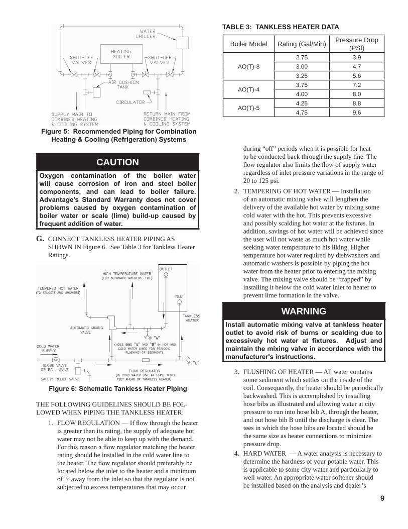
THE FOLLOWING GUIDELINES SHOULD BE FOL-LOWED WHEN PIPING THE TANKLESS HEATER:
1. FLOWREGULATION—Ifflowthroughtheheateris greater than its rating, the supply of adequate hot water may not be able to keep up with the demand. Forthisreasonaflowregulatormatchingtheheaterrating should be installed in the cold water line to theheater.Theflowregulatorshouldpreferablybelocated below the inlet to the heater and a minimum of 3’ away from the inlet so that the regulator is not subjected to excess temperatures that may occur
Figure 5: Recommended Piping for Combination Heating & Cooling (Refrigeration) Systems
CAUTIONOxygen contamination of the boiler water will cause corrosion of iron and steel boiler components, and can lead to boiler failure. Advantage's Standard Warranty does not cover problems caused by oxygen contamination of boiler water or scale (lime) build-up caused by frequent addition of water.
G. CONNECT TANKLESS HEATER PIPING AS SHOWN IN Figure 6. See Table 3 for Tankless Heater Ratings.
Figure 6: Schematic Tankless Heater Piping
Boiler Model Rating (Gal/Min) Pressure Drop (PSI)
AO(T)-32.75 3.93.00 4.73.25 5.6
AO(T)-43.75 7.24.00 8.0
AO(T)-54.25 8.84.75 9.6
TABLE 3: TANKLESS HEATER DATA
during “off” periods when it is possible for heat to be conducted back through the supply line. The flowregulatoralsolimitstheflowofsupplywaterregardless of inlet pressure variations in the range of 20 to 125 psi.
2. TEMPERING OF HOT WATER — Installation of an automatic mixing valve will lengthen the delivery of the available hot water by mixing some cold water with the hot. This prevents excessive andpossiblyscaldinghotwateratthefixtures.Inaddition, savings of hot water will be achieved since the user will not waste as much hot water while seeking water temperature to his liking. Higher temperature hot water required by dishwashers and automatic washers is possible by piping the hot water from the heater prior to entering the mixing valve. The mixing valve should be “trapped” by installing it below the cold water inlet to heater to prevent lime formation in the valve.
WARNINGInstall automatic mixing valve at tankless heater outlet to avoid risk of burns or scalding due to excessively hot water at fixtures. Adjust and maintain the mixing valve in accordance with the manufacturer's instructions.
3. FLUSHING OF HEATER — All water contains some sediment which settles on the inside of the coil. Consequently, the heater should be periodically backwashed. This is accomplished by installing hose bibs as illustrated and allowing water at city pressure to run into hose bib A, through the heater, and out hose bib B until the discharge is clear. The tees in which the hose bibs are located should be the same size as heater connections to minimize pressure drop.
4. HARD WATER — A water analysis is necessary to determine the hardness of your potable water. This is applicable to some city water and particularly to well water. An appropriate water softener should be installed based on the analysis and dealer’s

10
recommendation.Thisisnotonlybeneficialtothetanklessheaterbuttopipingandfixturesplusthemanyotherbenefitsderivedfromsoftwater.
H. INSTALL SMOKEPIPE — The Advantage Series boilershouldbeventedintoafireclaytile-linedmasonry chimney or chimney constructed from type L vent or a factory built chimney that complies with the type HT requirements of UL103. The chimney and ventpipeshallhaveasufficientdraftatalltimes,toassure safe proper operation of the boiler. See Figure 7 for recommended installation.1. Install a draft regulator following the instructions
furnished with the regulator. See Figure 8 for draft regulator locations.
2. Consider the chimney overall. Chimneys that have a high heat loss may become less suitable as the heatlossofthehomegoesdownandtheefficiencyof the boiler installed goes up. Most homes have a chimney appropriate for the fuel and the era in which the home was built. That may have been a coalfiredoraninefficientoilfiredboilerbuiltintoa home without insulation or storm windows. With increasing fuel prices that home probably has been insulatedandfittedwithstormwindowssothatthe heat loss of the home has been reduced. This requires less fuel to be burned and sends less heat up the chimney.
Anewboilerprobablyhasahigherefficiencythanthe boiler being replaced. That probably means that the stack temperature from the new boiler will be lower than that from the old boiler and with less room air being drawn up the chimney to dilute the stack gases. The combination of a large uninsulated chimney,reducedfiringrate,reducedfiringtime,lower stack temperature and less dilution air can,
Figure 7: Recommended Smokepipe Arrangement and Chimney Requirements
Figure 8: Proper and Improper Locations of Draft Regulator

11
Figure 9
Lift "H"(See Figure)
Maximum Length of Tubing"H" + "R" (See Figure)
3/8" ODTubing (3 GPH)
1/2" ODTubing (3 GPH)
0' 84' 100'1' 78' 100'2' 73' 100'3' 68' 100'4' 63' 100'5' 57' 100'6' 52' 100'7' 47' 100'8' 42' 100'9' 36' 100'
10' 31' 100'11' 26' 100'12' 21' 83'13' --- 62'14' --- 41'
TABLE 4: SINGLE STAGE uNITS (3450 RPM) TWO PIPE SYSTEMS
in some cases, contribute to the condensing of small amounts of water vapor in the chimney. Such condensation, when it occurs, can cause chimney deterioration. In extreme cases, condensed water may be visible on the outside of the breeching or chimney. In those extreme cases, the chimney may have to be lined to insulate the chimney and thus prevent the condensation. The addition of dilution air into the chimney may assist in drying the chimney interior surfaces.
A massive chimney on a cold, or exposed outside wall may have produced adequate draft when it wasfiredwithahigherinputandgreatervolumesof heated gases. With reduced input and volume, the draft may be severely affected. In one instance research showed a new chimney of adequate sizing produced only .035" W.C. after 30 minutes ofcontinuousfiringat13.0%CO2. Outside wall chimneys take longer to heat up and can have .00" W.C. draft at burner startup. You may have to consideraspecialalloychimneyfluelinerwithinsulation around it and a stabilizing draft cap or even a draft inducing fan in severe cases.
3. For the same reasons as in 2. above, heat extractors mounted into the breeching are not recommended.
I. FUEL UNITS AND OIL LINES SINGLE-PIPE OIL LINES Standard burners are
provided with single-stage 3450 rpm fuel units with the by-pass plug removed for single-pipe installations.
The single-stage fuel unit may be installed single-pipe with gravity feed or lift. Maximum allowable lift is 8 feet. See Figure 9.
IMPORTANTSingle-pipe installations must be absolutely airtight or leaks or loss of prime may result. Bleed line and fuel unit completely.
TWO-PIPE OIL LINES For two-pipe systems where more lift is required, the two-stage fuel unit is recommended. Table 4 (single-stage) and Table 5 (two-stage) show allowable lift and lengths of 3/8-inch and 1/2-inch OD tubing for both suction and return lines. Refer to Figure 10.
Be sure that all oil line connections are absolutely airtight. Check all connections and joints. Flared fittingsarerecommended.Donotusecompressionfittings.
Open the air-bleed valve and start the burner. For clean bleed, slip a 3/16" ID hose over the end of the bleed valve and bleed into a container. Continue to bleed for 15 seconds after oil is free of air bubbles. Stop burner and close valve.
Figure 10

12
J. SINGLE ZONE WIRING1. 120 Volt Wiring - The boiler should be provided
with its own 15A branch circuit with fused disconnect. All 120 volt connections are made inside the HydroStat relay as follows (see Figure 11).
•Hot("black")-WireNutwithBlackwireofON/ OFF Toggle Switch •Neutral("white")-Terminal"L2" •Ground("green"orbare)-Groundscrewonthe
case2. Thermostat Wiring - Follow thermostat
manufacturer instructions. To insure proper thermostat operation, avoid installation in areas of poor air circulation, hot spots (near any heat source or in direct sunlight), cold spots (outside walls, walls adjacent to unheated areas, locations subject to drafts). Provide Class II circuit between thermostat and boiler. Connect thermostat wire leads to terminals "T" and "T" inside the HydroStat (see Figure 11).
TABLE 5: TWO-STAGE uNITS (3450 RPM) TWO-PIPE SYSTEMS
Lift "H"(See Figure)
Maximum Length of Tubing"H" + "R" (See Figure)
3/8" ODTubing (3 GPH)
1/2" ODTubing (3 GPH)
0' 93' 100'2' 85' 100'4' 77' 100'6' 69' 100'8' 60' 100'10' 52' 100'12' 44' 100'14' 36' 100'16' 27' 100'18' --- 76'

13
Figure 11: Wiring Diagram for Water BoilersWith Beckett AFG Burner and Split Controls
SEQuENCE OF OPERATION LESS TANKLESS HEATERA call for heat by the thermostat energizes the HydroStat control which in turn energizes the primary control. The burner will initiate ignition after completing a 15 second pre-purge cycle. If burner ignites within approximately 45 seconds and the cad cell sees flame, the burner will continue to operate until the call for heat is satisfied or the setting of the high limit is reached. The circulator will operate as long as the thermostat is calling for heat. If the thermostat is not satisfied and the high limit is reached, the circulator will continue to operate, and the burner will stop until the high limit is closed by a drop in boiler water temperature.
SEQuENCE OF OPERATION WITH TANKLESS HEATER A call for heat by the thermostat energizes the HydroStat control which in turn energizes the primary control. The burner will initiate ignition after completing a 15 second pre-purge cycle. If burner ignites within approximately 45 sec-onds and the cad cell sees flame the burner will continue to operate until the call for heat is satisfied. The circulator will also operate when the thermostat calls for heat if the boiler water temperature is up to the setting of the low limit in the Hydrostat control. If boiler water temperature is below the low limit setting the burner will operate but the circulator will not, giving preference to the domestic hot water demand. On call for heat by the thermostat the burner will continue to operate until the thermostat is satisfied or the setting of the high limit is reached. If the thermostat is not satisfied when the high limit is reached the burner will stop but the circulator will continue to operate until the thermostat is satisfied. Any time the boiler water temperature drops below the setting of the low limit the burner will be energized in order to maintain domestic water temperature.

14
III. Indirect Water Heater Piping
A. CONNECT Indirect Water Heater Piping as shown in Figure 12. Refer to Indirect Water Heater Instruction Manual for additional installation information.
Figure 12: Indirect Water Heater Piping on Advantage Series Water Boiler
Advantage SERIES WATER BOILER - Figure 12 shows indirect water heater piping on typical hot water heating system. Boiler piping is the same as for any two-zone system. Figure 12 shows circulator zoning, which is usually preferred for indirectwaterheaters.Sizethecirculatorandindirectwaterheaterpipingtoobtaintheboilerwaterflowthroughtheindirect water heater called for by the indirect water heater manufacturer. Refer to the indirect water heater instruction manual for additional details.

15
IV. Operating and Service Instructions
F. REMOVE GUN ASSEMBLY1. Advantage Series boilers are equipped with Beckett
AFG burners. Items to be checked are nozzle size, head size, gun setting, and positioning of electrodes. This information is shown in Figure 13 and Table 6 at rear of manual.
2. Reinstall gun assembly.
A. ALWAYS INSPECT INSTALLATION BEFORE STARTING BURNER.
B. FILL HEATING SYSTEM WITH WATER.1. Hot Water Boilers: Fill entire Heating System with
water and vent air from system. Use the following procedure on a Series Loop System installed as per Figure 4:a. Close all but one zone valve.b. Open drain valve on boiler.c. Openfillvalve.d. Close purge valve.e. Open relief valve on boiler.f. Allow water to run out of drain valve until zone
hasbeenpurgedofairandfilledwithwater.g. Open zone valve to the second zone to be
purged,thenclosethefirst.Repeatthisstepuntilall zones have been purged but always have one zone open. At completion open all zone valves.
h. Close drain valve.i. When water discharges from relief valve, release
the lever on the top of the relief valve, allowing it to close.
j. Continuefillingthesystemuntilthepressuregaugereads12psi.Closefillvalve.
C. CHECK CONTROLS, WIRING AND BURNER to be sure that all connections are tight and burner is rigid, that all electrical connections have been completed and fusesinstalled,andthatoiltankisfilledandoillineshave been tested.
D. LUBRICATION1. Follow instruction on burner and circulator
label to lubricate, if oil lubricated. Most motors currently used on residential type burners employ permanently lubricated bearings and thus do not requireanyfieldlubrication.Waterlubricatedcirculatorsdonotneedfieldlubrication.
2. Do not over-lubricate. This can cause as much trouble as no lubrication at all.
E. ADJUST CONTROL SETTINGS with burner service switch turned “ON”.1. SET ROOM THERMOSTAT about 10°F below
room temperature.2. PRESS RED RESET BUTTON on the 7505
GeniSys Burner Control and release.3. See HydroStat Model 3250 Installation Instructions
and Operating Manual for adjusting high limit, low limitandeconomyfittings.
Figure 13: "L1" and "V1" Head Electrode Positioning and Gun Setting (Beckett AFG)
G. ADJUST OIL BURNER BEFORE STARTING.1. SET BURNER AIR BAND AND AIR SHUTTER,
see Table 6 at rear of manual.2. OPEN ALL OIL LINE VALVES.3. ATTACH A PLASTIC HOSE TO FUEL PUMP
VENT FITTING and provide a pan to catch the oil.4. OPEN FLAME OBSERVATION DOOR on front of
boiler.
H. START OIL BURNER.1. Openventfittingonfuelpump.2. TURN ‘ON’ BURNER service switch and allow
burnertorununtiloilflowsfromventfittingin a SOLID stream without air bubbles for approximately 10 seconds.
3. Closeventfittingandburnerflameshouldstartimmediately after pre-purge is complete. Pre-purge preventsburnerflameuntil15secondshaselapsedafter initial power is applied to burner. During pre-purge, the motor and ignitor will operate but the oil valve will remain closed. Refer to Oil Primary Control Instructions for more details.

16
I. ADJUST OIL BURNER WHILE OPERATING. (flamepresent)1. ADJUST DRAFT REGULATOR for a draft of
—.02”(watergauge)overthefireafterchimneyhas reached operating temperature and while burner is running.
2. READJUST THE AIR BAND / AIR DAMPER SETTING on burner for a light orange colored flamewhilethedraftoverthefireis-.02”.Useasmoke tester and adjust air for minimum smoke (not to exceed #1) with a minimum of excess air. Make finalcheckusingsuitableinstrumentationtoobtaina CO2of11.5to12.5%withdraftof-.02”(watergauge)infirebox.Thesesettingswillassureasafeandefficientoperatingcondition.Iftheflameappearsstringyinsteadofasolidfire,tryanothernozzle of the same type. Flame should be solid and compact. After all adjustments are made recheck for adraftof-.02”overthefire.
Figure 14: Adjusting Fuel Pump Pressure
3. READJUST THE HEAD / TURBULATOR SETTING only if necessary and applicable.a. Adjusting the head can also be used to optimize
the smoke and CO2 readings. 4. TURN “OFF” BURNER and remove pressure
gauge. Install gauge port/bleeder plug and tighten. Start burner again.
5. FLAME FAILURE The Advantage Series boiler controls operate the
burner automatically. If for unknown reasons theburnerceasestofireandtheresetbuttononthe primary control has tripped, the burner has experienced ignition failure. Before pressing the reset button call your heating contractor immediately.
WARNINGDo not attempt to start the burner when excess oil has accumulated, when the unit is full of vapor, or when the combustion chamber is very hot.
6. CAD CELL LOCATION AND SERVICE Theburnerissuppliedwithacadmiumsulfideflame
detector mounted at the factory, mounted on the bottom of the electronic ignitor. See Figure 15. To service cad cell or to replace the plug in portion, swing open the ignitor. After service is complete, be sure to fasten down the ignitor.
J. CHECK FOR CLEAN CUT OFF OF BURNER.1. AIR IN THE OIL LINE between fuel unit and
nozzle will compress when burner is on and will expand when burner stops, causing oil to squirt from nozzle at low pressure as burner slows down and causing nozzle to drip after burner stops. Usually cycling the burner operation about 5 to 10 times will rid oil line of this air.
2. IF NOZZLE CONTINUES TO DRIP, repeat Paragraph J, Step 1. If this does not stop the dripping, remove cutoff valve and seat, and wipe both with a clean cloth until clean, then replace and readjust oil pressure. If dripping or after burn persist replace fuel pump.
Figure 15: Cad Cell Location
4. ADJUST OIL PRESSURE for Beckett AFG burners (shut the burner off).a. When checking a fuel unit's operating pressure, a
reliable pressure gauge may be installed in either the bleeder port or the nozzle port. See Figure 14.
b. Locate oil pressure adjusting screw and turn screw for appropriate pump pressure, refer to Table 6 at rear of manual.
c. To check the cutoff pressure, deadhead a reliable pressure gauge onto the copper connector tube attached to the nozzle port. Run the burner for a short period of time. Shut the burner off. The pressure should drop and hold.
d. Remove the gauge and install bleeder port and/or reconnect the nozzle port line.

17
K. TEST CONTROLS.
WARNINGBefore installation of the boiler is considered complete, the operation of all boiler controls must be checked, particularly the primary control and high limit control.
1. CHECK THERMOSTAT OPERATION. Raise and lower thermostat setting as required to start and stop burner.
2. VERIFY PRIMARY CONTROL SAFETY FEATURES using procedures outlined in Instructions furnished with control or instructions as follows:CHECKOUT PROCEDUREa. Check wiring connections. Close line switch.
Check power at control.PRIMARY RELAY TESTb. Disconnect cad cell leads from quick connects
on underside at primary control. Reset safety switch.
c. Set controller to call for heat. Burner should start.
d. Jumper the quick connect terminals within 15 to 30 seconds. Burner should run.
e. Remove the quick connect terminals jumper. Burner shuts down in approximately 15 to 60 seconds.
f. If burner operates as described, relay is good. If not, install new relay.
CAD CELL TEST (see Figure 15)g. Open line switch. Clean cell face and see that
cell is securely in socket. Reconnect leads. Reset safety switch.
h. Close line switch. If burner starts and runs beyond safety switch cut-out time, cell is good. If not, install new cell.
3. WARNING — Check High Limit Control — Jumper Thermostat Terminals. Allow burner to operate until shut-down by limit. Installation is not considered complete until this check has been made.REMOVE JUMPER.
4. CHECK OPERATING CONTROL on boiler equipped with tankless heaters. With burner off, draw hot water until burner starts, then turn off hot water and check burner shut-down.
IF CONTROLS DO NOT MEET REQUIREMENTS AS OUTLINED ABOVE, REPLACE CONTROL AND REPEAT CHECK-OUT PROCEDURES.

18
V. Maintenance and Service Instructions
A. WATER BOILERS
1. Filling of boiler and system. GENERAL — In a hot water heating system, the
boiler and entire system (other than the expansion tank) must be full of water for satisfactory operation. Water should be added to the system until the boiler pressure gauge registers 12 psi. To insure that the system is full, water should come out of all air vents when opened.
2. BOILING OUT OF BOILER AND SYSTEM. The oil and grease which accumulate in a new hot water boiler can be washed out in the following manner:a. Remove relief valve using extreme care to avoid
damaging it.b. Add an appropriate amount of recommended boil
out compound.c. Replace relief valve.d. Fill the entire system with water.e. Startfiringtheboiler.f. Circulate the water through the entire system.g. Vent the system, including the radiation.h. Allow boiler water to reach operating
temperature, if possible.i. Continue to circulate the water for a few hours.j. Stopfiringtheboiler.k. Drain the system in a manner and to a location
that hot water can be discharged with safety.l. Remove plugs from all available returns and
wash the water side of the boiler as thoroughly as possible, using a high-pressure water stream.
m.Refillthesystemwithfreshwater.3. Add appropriate boiler water treatment compounds
asrecommendedbyyourqualifiedwatertreatmentcompany.
4. Make pH or Alkalinity Test. After boiler and system have been cleaned and
refilledaspreviouslydescribed,testthepHofthe water in the system. This can easily be done by drawing a small sample of boiler water and testing with hydrion paper which is used in the same manner as litmus paper, except it gives specificreadings.Acolorchartonthesideofthesmall hydrion dispenser gives the reading pH. Hydrion paper is inexpensive and obtainable from any chemical supply house or through your local druggist. The pH should be higher than 7 but lower than 11. Add some of the washout chemical (caustic soda), if necessary, to bring the PH within the specifiedrange.
5. Boiler is now ready to be put into service.
B. EXCESSIVE MAKE-UP WATER A leaky system will increase the volume of make-up
watersuppliedtotheboiler,whichcansignificantlyshorten the life of the boiler. Entrained in make-up water are dissolved minerals, salts and oxygen. When the fresh, cool make-up water is heated in the boiler, the minerals fall out as sediment, the salts coat the inside of the boiler, and the oxygen escapes as a gas. The accumulation of sediment eventually isolates the water from contacting the cast iron. When this happens the cast iron in that area gets extremely hot and eventually cracks. The presence of free oxygen or chloride salts in the boiler corrodes the cast iron from the inside. More make-up water and higher concentrations of contaminants damage the boiler sooner. Our warranty does not cover corrosion and sediment-related damage. Clearly it is in everyone’s best interest to prevent this type of failure. You can do your part by ensuring that your system is leak-free, keeping leakage to less than 2 percent of the total water volume each month.
C. HINTS ON COMBUSTION1. NOZZLES — Although the nozzle is a relatively
inexpensive device, its function is critical to the successful operation of the oil burner. The selection of the nozzle supplied with the Advantage boiler is the result of extensive testing to obtain the best flameshapeandefficientcombustion.Otherbrandsof the same spray angle and spray pattern may be used but may not perform at the expected level of CO2 and smoke. Nozzles are delicate and should be protected from dirt and abuse. Nozzles are mass-produced and can vary from sample to sample. For all of those reasons a spare nozzle is a desirable item for a serviceman to have.
2. FUEL LEAKS — Any fuel leak between the pump and the nozzle will be detrimental to good combustion results. Look for wet surfaces in the air
IMPORTANTIF, DURING NORMAL OPERATION, IT IS NECESSARY TO ADD MORE WATER THAN INDICATED BELOW, CONSULT A QUALIFIED SERVICE TECHNICIAN TO CHECK YOuR SYSTEM FOR LEAKS.
Model No. Gallons Per Month
Gallons Per Year
AO(T)-3 0.3 4
AO(T)-4 0.4 5
AO(T)-5 0.5 6

19
9. FLAME SHAPE — Looking into the combustion chamberthroughtheobservationdoor,theflameshould appear straight with no sparklers rolling up towardthecrownofthechamber.Iftheflamedragsto the right or left, sends sparklers upward or makes wet spots on the target wall, the nozzle should be replaced. If the condition persists look for fuel leaks, air leaks, water or dirt in the fuel as described above.
10. HIGH ALTITUDE INSTALLATIONS Air settings must be increased at high altitudes. Use
instrumentsandsetfor11.5to12.5%CO2.11. START-UP NOISE — Late ignition is the cause of
start-up noises. If it occurs recheck for electrode settings,flameshape,airorwaterinthefuellines.
12.SHUTDOWNNOISE—Iftheflamerunsoutofairbefore it runs out of fuel, an after burn with noise may occur. That may be the result of a faulty cut-off valve in the fuel pump, or it may be air trappedinthenozzleline.Itmaytakeseveralfiringcycles for that air to be fully vented through the nozzle.Waterinthefuelorpoorflameshapecanalsocause shut down noises.
NOTICECHECK TEST PROCEDuRE. A very good test for isolating fuel side problems is to disconnect the fuel system and with a short length of tubing, fire out of an auxiliary five gallon pail of clean, fresh, warm #2 oil from another source. If the burner runs successfully when drawing out of the auxiliary pail then the problem is isolated to the fuel or fuel lines being used on the jobsite.
D. ATTENTION TO BOILER WHILE NOT IN OPERATION1. IMPORTANT:
IF BOILER IS NOT USED DURING WINTER TIME, IT MUST BE FULLY DRAINED TO PREVENT FREEZE DAMAGE.
2. Always keep the manual fuel supply valve shut off if the burner is shut down for an extended period of time.
WARNINGThis boiler contains controls which may cause the boiler to shut down and not restart without service. If damage due to frozen pipes is a possibility, the heating system should not be left unattended in cold weather; or appropriate safeguards and alarms should be installed on the heating system to prevent damage if the boiler is inoperative.
3. To recondition the heating system in the fall season after a prolonged shut down, follow the instructions outlined in Section IV, Paragraphs A through K.
tube, under the ignitor, and around the air inlet. Any such leaks should be repaired as they may cause erratic burning of the fuel and in the extreme case maybecomeafirehazard.
3. AIR LEAKS — Any such leaks should be repaired, as they may cause erratic burning of the fuel and in extremecasesmaybecomeafirehazard.
4. SUCTION LINE LEAKS - Whatever it takes, The Oil Must Be Free of
Air. This can be a tough problem , but it must be resolved. Try bleeding the pump through a clear tube. There must be no froth visible. There are various test kits available to enable you to look at the oil through clear tube. There must be no froth visible. There are various test kits available to enable you to look at the oil through clear tubing adaptedtothesupplylineatthepumpfitting.Aireliminators are on the market that have potential. Also, electronic sight glasses are being used with good success. At times, new tubing must be run to thetankornewfittingsputon.Justmakesureyouget the air out before you leave.
Any air leaks in the fuel line will cause an unstable flameandmaycausedelayedignitionnoises.Useonlyflarefittingsinthefuellines.
5. GASKETLEAKS—If11.5to12.5%CO2 with a #1 smoke cannot be obtained in the breeching, look for air leaks around the burner mounting gasket, observation door, and canopy gasket. Such air leaks will cause a lower CO2 reading in the breeching. The smallerthefiringratethegreatereffectanairleakcan have on CO2 readings.
6. DIRT—Afuelfilterisagoodinvestment.Accidental accumulation of dirt in the fuel system can clog the nozzle or nozzle strainer and produce a poor spray pattern from the nozzle. The smaller the firingrate,thesmallertheslotsbecomeinthenozzleand the more prone to plugging it becomes with the same amount of dirt.
7. WATER — Water in the fuel in large amounts will stall the fuel pump. Water in the fuel in smaller amounts will cause excessive wear on the pump, but more importantly water doesn’t burn. It chills theflameandcausessmokeandunburnedfueltopass out of the combustion chamber and clog the fluewaysoftheboiler.
8. COLD OIL — If the oil temperature approaching the fuel pump is 40°F or lower poor combustion or delayed ignition may result. Cold oil is harder to atomize at the nozzle. Thus, the spray droplets get largerandtheflameshapegetslonger.Anoutsidefuel tank that is above grade or has fuel lines in a shallow bury is a good candidate for cold oil. The best solution is to bury the tank and lines deep enough to keep the oil above 40°F.

20
VI. Boiler Cleaning
Figure 16: Cleaning of Boiler Flueways
A. CLEAN THE FLUEWAYS (See Figure 16).1. Disconnect oil line(s) and remove burner and burner
mounting plate. See Figure 1.2. Lay protective cloth or plastic over combustion
chamber blanket.3. Remove the smokepipe as necessary to gain access
to the boiler canopy.4. Remove the jacket top panels.5. Remove the canopy being careful not to damage the
canopy gaskets.6. Usinga1¼”diameterwireorfibrebristlebrush
(30”handle)cleantheflueways.Brushfromthetopusing diagonal strokes for best results. DO NOT allow brush to strike the target wall or liner in the chamber.
B. CLEAN TOP OF BOILER SECTIONS.1. Brush and vacuum the tops of the boiler sections.
C. CLEAN THE FIREBOX.1. Usingwireorfibrebristlebrush,cleancrown
of boiler and inside of water legs. DO NOT allow brush to strike target wall or blanket in the combustion chamber.
D. AFTER CLEANING, remove protective cloth with debris and vacuum as necessary, but be careful not to damage blanket. Inspect target wall, combustion chamber blanket and burner mounting plate insulation for signs of damage. If damaged, replace as needed.
E. REASSEMBLE BOILER. CAUTION: Do not start the burner unless canopy,
smokepipe and burner swing door are secured in place.1. Install the canopy taking care to align the gaskets
withoutblockingtheflueways.Ifgasketisdamaged,replace as needed.
2. Close and secure burner swing door to front section with fasteners.
3. Reconnect oil line(s).4. Reinstall Top Panels and secure with sheet metal
screws.5. Reinstall smokepipe on canopy and secure to collar
with sheet metal screws.
WARNINGAll boiler cleaning must be completed with burner service switch turned off.
WARNINGThe boiler must be connected to an approved chimney in good condition. Serious property damage could result if the boiler is connected to a dirty or inadequate chimney. The interior of the chimney flue must be inspected and cleaned before the start of the heating season and should be inspected periodically throughout the heating season for any obstructions. A clean and unobstructed chimney flue is necessary to allow noxious fumes that could cause injury or loss of life to vent safely and will contribute toward maintaining the boiler's efficiency.

21
Important Product Safety InformationRefractory Ceramic Fiber Product
Warning:The Repair Parts list designates parts that contain refractory ceramic fibers (RCF). RCF has been classified as a possible human carcinogen. Whenexposed to temperatures above 1805°F, such as during direct flame contact,RCF changes into crystalline silica, a known carcinogen. When disturbed as a result of servicing or repair, these substances become airborne and, if inhaled, may be hazardous to your health.
AVOID Breathing Fiber Particulates and Dust
Precautionary Measures:Do not remove or replace RCF parts or attempt any service or repair work involving RCF without wearing the following protective gear:
1. A National Institute for Occupational Safety and Health (NIOSH) approved respirator
2. Long sleeved, loose fitting clothing3. Gloves4. Eye Protection
• Take steps to assure adequate ventilation.• Wash all exposed body areas gently with soap and water after contact.• Wash work clothes separately from other laundry and rinse washing
machine after use to avoid contaminating other clothes. • Discard used RCF components by sealing in an airtight plastic bag. RCF
and crystalline silica are not classified as hazardous wastes in the United States and Canada.
First Aid Procedures:• If contact with eyes: Flush with water for at least 15 minutes. Seek
immediate medical attention if irritation persists.• If contact with skin: Wash affected area gently with soap and water.
Seek immediate medical attention if irritation persists.• If breathing difficulty develops: Leave the area and move to a location
with clean fresh air. Seek immediate medical attention if breathing difficulties persist.
• Ingestion: Do not induce vomiting. Drink plenty of water. Seek immediate medical attention.

22
All Advantage Repair Parts may be obtained through F.W.Webb Company, 1 Bon Terrain Drive, Amherst, NH 03031
VII. Repair Parts
Bare Boiler Assembly (Exploded View)

23
Item No. Description
[Quantity] Part Number
AO(T)-3 AO(T)-4 AO(T)-5
Bare Boiler Assembly
1A
Bare Boiler Assembly with Rear Target Wall and Front Heater Opening 104118-03 104118-04 104118-05
Bare Boiler Assembly with Rear Target Wall andLess Front Heater Opening 104123-03 104123-04 104123-05
1B Replacement Canopy Assembly with Gasket and Hardware 104937-03 104937-04 104937-05
1C222AR Replacement Assembly with Gasket and Hardware 104139-01222AR Replacement Gasket Only 8036068
1DBurner Swing Door Assembly with Insulation, Port Cover and Hardware 104140-01
Burner Swing Door Insulation Only 820200011E Burner Swing Door Hinge Loop Bracket [2] 100795-021F Combustion Chamber Liner 82020031 82020041 820200511G Rear Target Wall 82020002

24
AO(T)-3 Thru AO(T)-5 Water Boilers - Jacket and Trim

25
Item No. Description
[Quantity] Part Number
AO(T)-3 AO(T)-4 AO(T)-5
Jacket and Trim2A Jacket Set Assembly with Labels and Hardware 104133-03 104133-04 104133-05
2B TACO 00R Circulator with Gaskets 104130-01
2C 1-1/2 NPT Flange and Hardware Kit 60560062D 30 PSI Relief Valve 81660319
2E Barometric Draft Control 8116288 8116289 104101-01
2F Temperature / Pressure Gauge 100282-01
2G Burner Disconnect J-box 103957-01
2H Burner Disconnect J-box Cover 103958-01
2J Power Outlet Connector 8136522
2K Burner with Gasket 0.75 GPH -104095-01
1.25 GPH - 104096-01
1.75 GPH - 104097-01
2L Burner Flange Gasket 8202703
2MHydroStat High Limit less Heater 104579-01
HydroStat High Limit with Heater 104580-01
2NElectro-Well (short) for use less Heater 104098-01
Electro-Well (long) for use with Heater 103941-01
Disconnect Wiring Harness (not shown) 103946-01

26
TABLE 6: BURNER SPECIFICATIONS
Beckett AFG
Boiler Model Firing Rate GPH
Settings Nozzle 2 Pump PressureHead
(Setting)Air
ShutterAir
Band GPH x Angle Type
AO(T)-3
1 0.65 L1 1 1 0.55 x 60B (Hago) 140
1 0.75 L1 10 2 0.65 x 60B (Hago) 140
1.00 L1 5 2 0.85 x 60B (Hago) 140
AO(T)-41.25 V1(0) 10 0.5 1.00 x 60B (Hago) 140
1.50 V1(0) 10 6 1.25 x 60B (Hago) 140
AO(T)-51.75 V1(3) 6 6 1.35 x 45B (Hago) 175
2.00 V1(4) 8 4 1.50 x 45B (Hago) 175
1 Beckett low firing rate baffle required on AO(T)-3 0.65 and 0.75 GPH applications only. 2 Single stage fuel pump pressure has been preset by the burner manufacturer.
VIII. Appendix - Burner Specifications

27

28