installation & operating instructions for genesys series ... genesys 1...medical inc....
TRANSCRIPT
Tri-Tech Medical Inc., 810 Center Road, Bldg.-E, Avon, Ohio 44011Tel. 1-800-253-8692 -or- 440-937-6244 Fax. 440-937-5060
Web site www.tri-techmedical.com E mail address: [email protected] 1 -
Tri-TechMedical Inc.
Manufacturer of Medical Gas Pipeline Equipment
Installation & Operating Instructions forGenesys
Series Manifolds
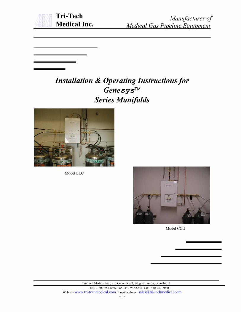
Model LLU
Model CCU

Tri-Tech Medical Inc., 810 Center Road, Bldg.-E, Avon, Ohio 44011Tel. 1-800-253-8692 -or- 440-937-6244 Fax. 440-937-5060
Web site www.tri-techmedical.com E mail address: [email protected]
Tri-TechMedical Inc.
Genesys Manifold SystemsFeatures & Benefits
Features & Benefits
• Fully automatic changeover – no valves or levers to reset after each changeover
• Field upgradeable design – kits allow unit to be changed from i.e. cylinders to portable bulk or fromlower delivery pressure to higher delivery pressure
• Circuit board triggers all required NFPA 99 alarms – simplifying wiring and reducing cost
• Unit includes hi/low line pressure transducer – eliminating need to purchase hi/low pressure switch
• Easy to service layout/design
• Microprocessor based control panel incorporates LED’s and illuminated digital LED displaysreadable even in poor lighting conditions
• Electronic monitoring of circuits with error messages displayed for ease of maintenance
• Accurate, long life pressure transducers for monitoring of line pressure and bank pressures
• Analog gauges also provided for use in event of power failure
• Pressures may be displayed in PSIG / kPa / BAR
• Built in DISS gas specific emergency feed ports
• Built in emergency reserve bank ports
• Input power 110 VAC, 50 to 60 Hz
• Dual line pressure regulators on NFPA 99 models
• Gas specific header bar with integral check valves and cylinder pigtail assemblies
• Variety of header configurations available to meet the available space requirements of yourinstallation
• Available in weatherproof cabinet for outdoor installation

Tri-Tech Medical Inc., 810 Center Road, Bldg.-E, Avon, Ohio 44011Tel. 1-800-253-8692 -or- 440-937-6244 Fax. 440-937-5060
Web site www.tri-techmedical.com E mail address: [email protected] 3 -
Tri-TechMedical Inc. Table of Contents
ContentsGeneral Instructions ----------------- 4
Introduction---------------------------- 4
Features & Benefits ---------------------- 2
Installation - Control Cabinet ------ 5Mounting----------------------------------- 5Wiring -------------------------------------- 8Plumbing ----------------------------------- 6
Installation – Pigtails & Cylinders ---- 10
Remote Alarm Wiring ------------------- 9Alarm Pressure Settings------------------- 9
Start Up and Testing Procedures ----- 12
Model LLU Emergency Reserve------- 13Alarm and Regulator Set Points---------- 13
Cylinder Replacement & Handling --- 14
Line Delivery Pressure Adjustment--- 14
Replacement Parts-------------------- 16
General Maintenance ---------------- 15
Trouble Shooting Guide ------------- 17Table of Error Codes ---------------------- 15
Appendix AGlossary of Terms -------------------- 19
Appendix BTechnical Specifications ------------- 20
Appendix CModel CC Piping Schematic -------- 21
Appendix DModel LL Piping Schematic -------- 22
Appendix EModel CC Wiring Schematic ------- 23
Appendix FModel LL Wiring Schematic ------- 24
Appendix GHeater Wiring Schematic------------ 25
Appendix HField Adjustments--------------------- 26
Technical Assistance----Phone 800-253-8692
or 440-937-6244Fax 440-937-5060E-mail [email protected]

Tri-TechMedical Inc.
Genesys Manifold SystemsIntroduction & General Instructions
IntroductionTri-Tech Medical manifolds are cleaned for use with oxygen. Each system is tested for changeover, triggering ofalarms, leakage and flow. Each unit is designed and prepared for the indicated gas service. Tri-Tech Medicalmanifolds are built in accordance with the National Fire Protection Association and Compressed Gas Associationguidelines.
WarrantyAll Tri-Tech Medical manifolds are warranted against defects in material and workmanship for the period of one yearfrom date of purchase. All circuit boards are warranted against defects in material and workmanship for the period ofthree years from date of purchase.
General Instructions/Location & ShelterManifolds should be installed in accordance with guidelines stated by the National Fire Protection Association, theCompressed Gas Association, OSHA, and all applicable local codes. Carbon Dioxide and Nitrous Oxide manifoldsand cylinders should not be placed in a location where the temperature will exceed 120° F (49° C) or fall below 20° F(-7° C). The manifolds for all other gas services should not be placed in a location where the temperature will exceed120° F (49° C) or fall below 0° F (-18° C). A manifold placed in an open location should be protected against weatherconditions. During winter, protect the manifold from ice and snow. In summer, shade the manifold and cylindersfrom continuous exposure to direct sunlight.
Leave all protective covers in place until their removal is required for installation. This precaution will keep moisture and debrisfrom the piping interior.
CautionFailure to follow the following instructions can result in personal injury or property damage:
• Never permit oil, grease, or other combustible materials to come in contact with cylinders, manifold, andconnections. Oil and grease may react with explosive force when ignited while in contact with some gases– particularly oxygen and nitrous oxide.
• Cylinder and master valves should always be opened very slowly. Heat of recompression may ignitecombustible materials creating an explosive force.
• Pigtails should never be kinked, twisted, or bent into a radius smaller than 3 inches. Mistreatment maycause the pigtail to burst.
• Do not apply heat. Oil and grease may react with explosive force when ignited while in contact with somegases – particularly oxygen and nitrous oxide.
• Cylinders should always be secured with racks, chains, or straps. Unrestrained cylinders may fall over anddamage or break off the cylinder valve which may propel the cylinder from its current position.
• Oxygen manifolds and cylinders should be grounded. Static discharges and lightning may ignite materialsin an oxygen atmosphere, creating a fire or explosive force.
• Welding should not be performed near nitrous oxide piping. Excessive heat may cause the gas to dissociate,creating an explosive force.
• Remove all protective caps prior to assembly. The protective cap may ignite due to heat of recompressionin an oxygen system.
Tri-Tech Medical Inc., 810 Center Road, Bldg.-E, Avon, Ohio 44011Tel. 1-800-253-8692 -or- 440-937-6244 Fax. 440-937-5060
Web site www.tri-techmedical.com E mail address: [email protected]

Tri-Tech Medical Inc., 810 Center Road, Bldg.-E, Avon, Ohio 44011Tel. 1-800-253-8692 -or- 440-937-6244 Fax. 440-937-5060
Web site www.tri-techmedical.com E mail address: [email protected]
Tri-TechMedical Inc.
Genesys Manifold SystemsInstallation Instructions
Control Cabinet Installation
1. Determine and mark the vertical center line forinstallation of the manifold control cabinet.
2. Measure from the floor to a point 60” in height* abovethe finished floor of this vertical line. Using a level,mark a horizontal line at this point extendingapproximately 10” to the left and 10” to the right ofcenter. This line indicates the location for the bottomtwo mounting bolts of the manifold control cabinet.(* - suggested manifold height. Wall mounting heightsmay vary depending on available space, cylinder height,etc.)
3. Draw another horizontal line 12.5” above and parallel tothe lower horizontal line. This line should also extend7” to the left and 7” to the right of center. This lineindicates the location for the upper two mounting boltsof the manifold control cabinet.
4. Measuring from the vertical center line, along the twohorizontal lines, make a mark at 6 ¼” to the left andanother at 6 ¼” to the right of the vertical center line.These four locations are the mounting hole locations forthe manifold control cabinet. Install the manifoldcontrol cabinet using fasteners suitable for the type ofwall construction.
Header Installation
1. Attach the headers to the union on each side of themanifold control cabinet. Using a level, mark theplacement of mounting brackets while keeping theheader on a horizontal plane.
2. Remove the U – bolt assemblies from the headermounting brackets. Position the brackets so that the topof the bracket is aligned with the bottom of the headersand is centered between the cylinder connections. Theend bracket should be placed as close to the last cylinderas possible to provide the most support and stability.
60”
12.5”
12.5”
6.25”
Center Line
Tri-TechMedical Inc.
Genesys Manifold SystemsInstallation Instructions
1.
2.
Plum
1.
2.
3.
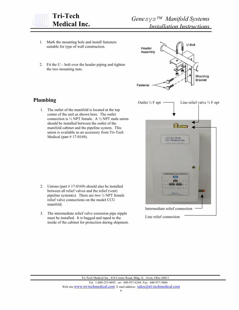
Mark the mounting hole and install fastenerssuitable for type of wall construction.
Fit the U – bolt over the header piping and tightenthe two mounting nuts.
Tri-Tech Medical Inc., 810 Center Road, Bldg.-E, Avon, Ohio 44011Tel. 1-800-253-8692 -or- 440-937-6244 Fax. 440-937-5060
Web site www.tri-techmedical.com E mail address: [email protected]
bing
The outlet of the manifold is located at the topcenter of the unit as shown here. The outletconnection is ½ NPT female. A ½ NPT male unionshould be installed between the outlet of themanifold cabinet and the pipeline system. Thisunion is available as an accessory from Tri-TechMedical (part # 17-0169).
Unions (part # 17-0169) should also be installedbetween all relief valves and the relief (vent)pipeline system(s). There are two ½ NPT femalerelief valve connections on the model CCUmanifold.
The intermediate relief valve extension pipe nipplemust be installed. It is bagged and taped to theinside of the cabinet for protection during shipment.
Outlet ½ F npt Line relief valve ½ F npt
Intermediate relief connection
Line relief connection

Tri-Tech Medical Inc., 810 Center Road, Bldg.-E, Avon, Ohio 44011Tel. 1-800-253-8692 -or- 440-937-6244 Fax. 440-937-5060
Web site www.tri-techmedical.com E mail address: [email protected]
Tri-TechMedical Inc.
Genesys Manifold SystemsInstallation Instructions
Plumbing
1. In addition to connecting the left & rightprimary and secondary portable bulkvessel supply banks, the LLU modelsmust also have a high pressure reservebank of cylinders connected to thecabinet to be in compliance with NFPA99 guidelines.
2. Knock outs have been provided on boththe left and right sides of the controlcabinet to allow for the high pressurereserve piping.
3. A check valve (part number CV-050F)must be installed between the emergencyreserve in use pressure transducer andthe high pressure reserve regulator.
4. The model LLU has one ½ NPT femaleline pressure relief valve connection andtwo ¼ NPT female intermediate pressurerelief valve connections.
Emergency reserve lowpressure transducer
High pressurereserve manifold
Emergency reserve inuse pressure transducer
Check valve
Emergency reserve in usepressure transducer withDISS demand check union
Intermediate relief valve
Line pressure relief valve

Tri-Tech Medical Inc., 810 Center Road, Bldg.-E, Avon, Ohio 44011Tel. 1-800-253-8692 -or- 440-937-6244 Fax. 440-937-5060
Web site www.tri-techmedical.com E mail address: [email protected]
Tri-TechMedical Inc.
Genesys Manifold SystemsInstallation Instructions
Electrical
1. Use one of the two ½” conduit knock-outs providedlocated nearest to the top left corner of the cabinetto route conduit to supply either 110 VAC to thepower supply. Note: Separate conduit should beused for low voltage wires (use knock outsprovided on the left side of the box).
2. Remove the power supply cover by loosening thetwo screws located at the top and bottom of thecover and then sliding the power supply cover tothe right until the screws are in the center of thetear-drop shaped cut out. Next, lift the cover until itclears the screw heads and the fuse. Allow thecover to rest on the dual line regulator assemblyplumbing just below the power supply.
3. Route wires of proper gauge (per local buildingcode requirement) through the power supplyconduit, thru the grommet on the power supplybracket and into the terminal strip.
Neutral
Load
Field Ground
4. Connect the 110 VAC facility emergency powersource electrical wiring to the terminal stripprovided on the front of the power supply mountingbracket (per photos right). (N = neutral, L = load,FG = field ground)
Conduit knockouts for110 VAC
Conduit knockouts forlow voltage alarm signals

Tri-Tech Medical Inc., 810 Center Road, Bldg.-E, Avon, Ohio 44011Tel. 1-800-253-8692 -or- 440-937-6244 Fax. 440-937-5060
Web site www.tri-techmedical.com E mail address: [email protected]
Tri-TechMedical Inc.
Genesys Manifold SystemsInstallation Instructions
Alarm Pressure Settings for CCU Models (all pressures in psig)Normal Delivery Press Line Relief Setting High Line Press Set Point Low Line Press Set Point Secondary In Use Set Point
50 75 60 40 200 left bank / 150 right bank80 150 96 64 300 left bank / 250 right bank
190 250 228 152 300 left bank / 250 right bank
Alarm Pressure Settings for LLU Models (all pressures in psig)Normal Delivery Press Line Relief Setting High Line Press Set Point Low Line Press Set Point Secondary In Use Set Point
50 75 60 40 95 both banks80 150 96 64 95 both banks
190 250 228 152 190 both banks
Wiring – remote alarms
1. Wires for remote alarms should be brought into thecabinet thru conduit or shielded cables (check localcode requirements) thru the knockouts on the left sideof the cabinet shown here. . Note: Separate conduitshould be used for high voltage wires – never runlow voltage wires in the same conduit as highvoltage wires.
2. If you are installing a model CCU (cylinder xcylinder) cabinet there are three alarm signalsrecommended per NFPA 99, High Line Pressure, LowLine Pressure and Reserve in Use. The CCU circuitboard will trigger all three of these alarms (no hi/lowpressure switch is required). The line pressuretransducer has been equipped with a 10’ cable andmay be installed outside of the cabinet – downstreamof the source or main line valve with the cable beingwired to the manifold circuit board.
3. As an option, the line pressure transducer may bemounted inside the cabinet (as shown here). In thisarrangement, a hi/low pressure switch will be requiredto meet the NFPA 99 recommendations. Note: thehi/low pressure switch would be wired directly to themaster alarm panels – not to the manifold circuitboard.
4. Remote alarm wires are connected to the circuit boardat the terminal gate labeled P2. Signal wires andCommon wires for Low Line Pressure, High LinePressure and Secondary in Use should be connected tothe terminals as indicated.
5. Note: all remote alarm terminals are normally closedwhen the gas pressure is in the normal range. Thehi/low set points pre-programmed into the manifoldcircuit board logic chip are as per the following charts:
Knock outs for low voltageremote alarm wiring
Line pressure transducer

Tri-Tech Medical Inc., 810 Center Road, Bldg.-E, Avon, Ohio 44011Tel. 1-800-253-8692 -or- 440-937-6244 Fax. 440-937-5060
Web site www.tri-techmedical.com E mail address: [email protected]
Tri-TechMedical Inc.
Genesys Manifold SystemsInstallation Instructions
Installing pigtails & attachingcylinders – CCU models
1. A fitting on one end of each pigtailis stamped with a flow directionarrow. Verify that the pigtail isoriented properly before connectingit to the manifold header.
2. Connect the pigtails to the valveoutlets on the manifold header withthe direction of flow from thecylinder to the header end of thepigtail. (Note – if the pigtail isinstalled backwards, gas will notflow from the cylinder to theheader).
3. Check the master valves to becertain they are open (turn counter-clockwise to open). (Note: themaster valve should always be leftopen. It is to be used only in theevent of an emergency).
4. SLOWLY open all cylinder valves(turn counter-clockwise to open).Check all cylinder and pigtailconnections for leaks using anoxygen safe leak test solution (anybubbles forming aroundconnections indicate leakage).
Flow direction arrow
Master valve
Attach pigtails toheader check valveoutlets using 1 1 /8”open end wrench
Tri-Tech Medical Inc., 810 Center Road, Bldg.-E, Avon, Ohio 44011Tel. 1-800-253-8692 -or- 440-937-6244 Fax. 440-937-5060
Web site www.tri-techmedical.com E mail address: [email protected]
Tri-TechMedical Inc.
Genesys Manifold SystemsInstallation Instructions
Minimum inlet pressure requirements for LLU Manifold
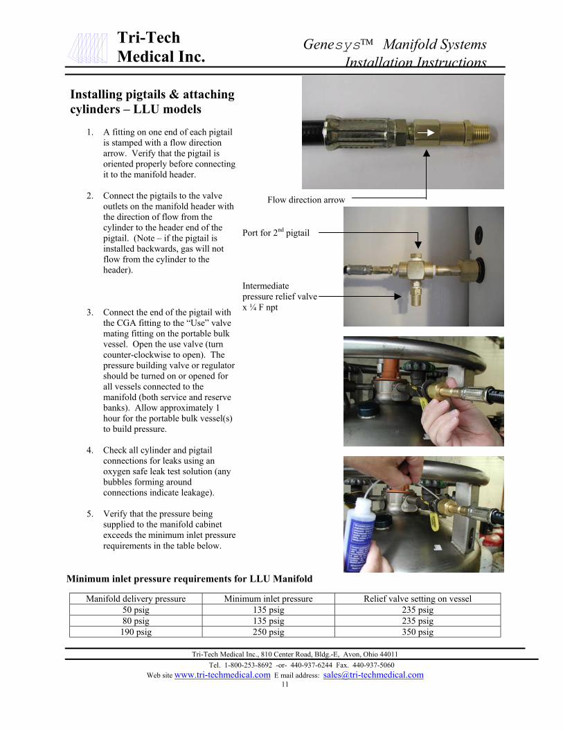
Manifold delivery pressure Minimum inlet pressure Relief valve setting on vessel50 psig 135 psig 235 psig80 psig 135 psig 235 psig190 psig 250 psig 350 psig
Installing pigtails & attachingcylinders – LLU models
1. A fitting on one end of each pigtailis stamped with a flow directionarrow. Verify that the pigtail isoriented properly before connectingit to the manifold header.
2. Connect the pigtails to the valveoutlets on the manifold header withthe direction of flow from thecylinder to the header end of thepigtail. (Note – if the pigtail isinstalled backwards, gas will notflow from the cylinder to theheader).
3. Connect the end of the pigtail withthe CGA fitting to the “Use” valvemating fitting on the portable bulkvessel. Open the use valve (turncounter-clockwise to open). Thepressure building valve or regulatorshould be turned on or opened forall vessels connected to themanifold (both service and reservebanks). Allow approximately 1hour for the portable bulk vessel(s)to build pressure.
4. Check all cylinder and pigtailconnections for leaks using anoxygen safe leak test solution (anybubbles forming aroundconnections indicate leakage).
5. Verify that the pressure beingsupplied to the manifold cabinetexceeds the minimum inlet pressurerequirements in the table below.
Flow direction arrow
Port for 2nd pigtail
Intermediatepressure relief valvex ¼ F npt

Tri-Tech Medical Inc., 810 Center Road, Bldg.-E, Avon, Ohio 44011Tel. 1-800-253-8692 -or- 440-937-6244 Fax. 440-937-5060
Web site www.tri-techmedical.com E mail address: [email protected]
Tri-TechMedical Inc.
Genesys Manifold SystemsStart Up & Checking Procedures
Start up & checking procedures
1. Turn on the 110 VAC to the unit. The digitaldisplay should illuminate showing all zeros for theLine Pressure, Left Bank Pressure and Right BankPressure (model CCU). Both the left & right bankRed (Depleted) LED’s should be illuminated andall digital displays should read zero. Both the leftand right bank Green (In Use) and Yellow LED’s(Ready) should be extinguished.
2. SLOWLY open one cylinder valve on the left bank.The left bank pressure gauge (inside the cabinet)and the digital display (on the outside of thecabinet) should show the full pressure of thecylinder. The Red (Depleted) LED for the left bankshould have extinguished leaving only the Green(In Use) LED illuminated.
3. SLOWLY open one cylinder valve on the rightbank. The right bank pressure gauge (inside thecabinet) and the digital display (on the outside ofthe cabinet) should show the full pressure of thecylinder. The Red (Depleted) and the Green (InUse) LED’s for the right bank should have bothextinguished and the Yellow (Ready) LED shouldhave illuminated.
4. Turn off all open left bank cylinder valves. Createa slight flow of gas in the delivery pipeline system.DISS demand valves have been provided on theline regulators. Mating DISS fittings may be usedto create a flow of gas within the manifold cabinet.The left bank pressure digital display and pressuregauge should fall and the control automaticallyswitches over to the right bank. Delivery pressureremains constant. The left bank Red (Empty) LEDwill illuminate. The reserve in use alarm shouldactivate on the master alarm(s). SLOWLY reopenthe cylinders on the left bank. The left bankpressure gauge and digital display should return tofull pressure. The left bank yellow (Ready) LEDwill illuminate simultaneously the left bank red(Empty) will extinguish. All remote reserve in usealarms will be canceled. Repeat step 4 to simulatean empty right bank.

Tri-TechMedical Inc.
Genesys Manifold SystemsEmergency Reserve – Model LLU
Model LLU – Emergency Reserve PressureSettings & Alarm Set Points
1. The model LLU includes digital displays for theemergency reserve bank pressure the intermediate areapressure.
Remote master alarms will be triggered by the model LLUfor the five required NFPA 99 alarms; high line pressure,low line pressure, secondary in use, emergency reserve inuse and emergency reserve low.
Refer to the chart below for information on setting thedelivery (outlet) pressure of the emergency reserve regulatorand pre-programmed emergency reserve in use andemergency reserve low alarm set points.
2. The emergency reserve low bank pressure transducer(part # 14-3001) should be installed on the extra port onthe RWP series manifold. This port is located prior(upstream) to the master valve and the regulator.
Emergency reserve low bank pressure transducerEmergency reserve in use pressure transducer
3. The emergency reserve in use pressure transducer (part# 14-3002) should be installed on copper tubing(provided by plumbing contractor) after (downstream)the check valve (part # CV-050F). Note: a DISSdemand check union assembly should also be installedin case this transducer would ever need to be replaced.
DISS demand check union assembly (part # PS-24 – oxy)Check valve (part # CV-050F)
4. Both the emergency reserve bank pressure transducerand the emergency reserve in use transducer must bewired to the manifold circuit board as indicated by thelabeling instruction. Remote master alarm signal andcommon wires must also be connected to the manifoldcircuit board as indicated by the labeling instruction.
Tri-Tech Medical Inc., 810 Center Road, Bldg.-E, Avon, Ohio 44011Tel. 1-800-253-8692 -or- 440-937-6244 Fax. 440-937-5060
Web site www.tri-techmedical.com E mail address: [email protected]
Manifold Delivery Pressure
Recommended EmergencyReserve Regulator Delivery
Pressure Setting
Pre-programmedEmergency Reserve in Use
alarm set point
Pre-programmedEmergency Reserve Low
alarm set point50 psig 65 psig 75 psig 1200 psig80 psig 70 psig 80 psig 1200 psig200 psig 170 psig 180 psig 1200 psig
Tri-Tech Medical Inc., 810 Center RoaTel. 1-800-253-8692 -or- 440-9
Web site www.tri-techmedical.com E mail add14
Tri-TechMedical Inc.
Genesys Manifold SystemsCylinder Replacement & Line Pressure Adjustment
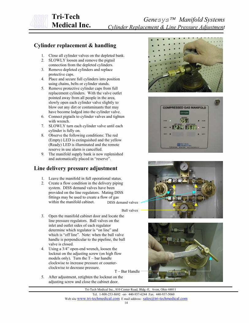
Cylinder replacement & handling
1. Close all cylinder valves on the depleted bank.2. SLOWLY loosen and remove the pigtail
connection from the depleted cylinders.3. Remove depleted cylinders and replace
protective caps.4. Place and secure full cylinders into position
using chains, belts or cylinder stands.5. Remove protective cylinder caps from full
replacement cylinders. With the valve outletpointed away from all people in the area,slowly open each cylinder valve slightly toblow out any dirt or contaminants that mayhave become lodged into the cylinder valve.
6. Connect pigtails to cylinder valves and tightenwith wrench.
7. SLOWLY turn each cylinder valve until eachcylinder is fully on.
8. Observe the following conditions: The red(Empty) LED is extinguished and the yellow(Ready) LED is illuminated and the remotereserve in use alarm is cancelled.
9. The manifold supply bank is now replenishedand automatically placed in “reserve”.
Line delivery pressure adjustment
1. Leave the manifold in full operational status.2. Create a flow condition in the delivery piping
system. DISS demand valves have beenprovided on the line regulators. Mating DISSfittings may be used to create a flow of gaswithin the manifold cabinet.
3. Open the manifold cabinet door and locate theline pressure regulators. Ball valves on theinlet and outlet sides of each regulatordetermine which regulator is “on line” andwhich is “off line”. Note: when the ball valvehandle is perpendicular to the pipeline, the ballvalve is closed.
4. Using a 3/4” open-end wrench, loosen thelocknut on the adjusting screw (on high flowmodels only). Turn the T – bar handleclockwise to increase pressure or counter-clockwise to decrease pressure.
5. After adjustment, retighten the locknut on theadjusting screw and close the cabinet door.
DISS demand valve
Ball valve
s
s
e
T – Bar Handld, Bldg.-E, Avon, Ohio 4401137-6244 Fax. 440-937-5060ress: [email protected]

Tri-Tech Medical Inc., 810 Center Road, Bldg.-E, Avon, Ohio 44011Tel. 1-800-253-8692 -or- 440-937-6244 Fax. 440-937-5060
Web site www.tri-techmedical.com E mail address: [email protected]
Tri-TechMedical Inc.
Genesys Manifold SystemsGeneral Maintenance & Error Codes
General Maintenance
Control Cabinet
Daily – Record line and bank pressuresMonthly – Check regulators, compression fittings
and valves for external leakage.Check valves for closure ability.
Annually – Check relief valve pressuresCheck regulator seats.
Manifold Headers & Pigtails
Daily – Observe nitrous oxide and carbon dioxidesystems for cylinder frosting or surfacecondensation. Should excessivecondensation or frosting occur it may benecessary to increase manifold capacity.
Monthly – Inspect valves for proper closure.Check pigtails for cleanliness, flexibility,wear, leakage, and thread damage.Replace damaged pigtails immediately.Inspect pigtail check valves for closureability.
Every 4 years – Replace all pigtails
Error Codes
This manifold is designed and equipped with someself-diagnostic software. A flashing error code willbe displayed on the left bank and right bankpressure displays when an error occurs. An errorindicates: a loose or disconnected or broken wire, amiss-connected wire, a bad transducer or an over-pressure situation.
ERR 001- Line pressure sensor
ERR 002 – Emergency reserve in use pressuresensor
ERR 003 – Left portable bulk bank pressure sensor
ERR 004 – Right portable bulk bank pressuresensor
ERR 005 – Left cylinder bank pressure sensor orhigh pressure emergency reserve pressure sensor.
ERR 006 – Right cylinder bank pressure sensor.
Error codes correspond from left to right with thesensor input wire terminal connections on the P3, P4and P5 circuit board positions.

Tri-Tech Medical Inc., 810 Center Road, Bldg.-E, Avon, Ohio 44011Tel. 1-800-253-8692 -or- 440-937-6244 Fax. 440-937-5060
Web site www.tri-techmedical.com E mail address: [email protected]
Tri-TechMedical Inc.
Genesys Manifold SystemsReplacement Parts
Item Part Number DescriptionPrimary Regulator & Repair Kits 68-0003 0 – 300 psig delivery, 3,000 psig inlet, 6 port
68-0003RK Rebuild kit for primary regulator 68-0003Line Regulators & Repair Kits 68-0004 5 – 125 psig standard flow line regulator
68-0004RK Rebuild kit for 5 - 125 standard flow line regulator 68-000468-0002 5 – 125 psig high flow line regulator68-0002RK Rebuild kit for 5 - 125 high flow line regulator 68-000268-0001 10 – 200 psig high flow line regulator68-0001RK Rebuild kit for 0 – 200 high flow line regulator 68-0001
Circuit Board 35-1001 Universal Manifold PLC Board35-1002 CCU Manifold PLC Board
Transducers/Sensors 14-3001 0 – 2,500 psig x ¼ M npt14-3002 0 – 500 psig x ¼ M npt14-3003 0 – 250 psig x DISS N214-3004 0 – 100 psig x DISS Oxygen14-3005 0 – 100 psig x DISS Medical Air14-3006 0 – 100 psig x DISS N2O14-3007 0 – 100 psig x DISS CO2
DISS Demand Check Union Assemblies PS-04 Nitrous Oxide ¼ M npt demand valve x 1/8 M npt nipplePS-08 CO2 ¼ M npt demand valve x 1/8 M npt nipplePS-12 N2 ¼ M npt demand valve x 1/8 M npt nipplePS-16 Medical Air ¼ M npt demand valve x 1/8 M npt nipplePS-24 Oxygen ¼ M npt demand valve x 1/8 M npt nipple
Solenoid Valves 48-1001 Used on CC – all gas services except N2, N2O & CO2 – Viton Seals48-1002 Used on CC – N2O & CO2 only – EPDM Seals48-1003 Used on CC for N2 & LL for OXY & N2 – Vtion Seals, left side48-1004 Used on CC for N2 & LL for OXY & N2 – Vtion Seals, right side48-1005 Used on LL for CO2 & N2O – EPDM Seals, left side48-1006 Used on LL for CO2 & N2O – EPDM Seals, right side
Power Supply AA400-C 110 VAC / 24 & 5 VDCGauges 14-1018 0 – 4,000 psig 1 ½” x 1/8 M npt center back
14-1016 0 – 400 psig 2” x ¼ M npt bottom port14-1017 0 – 400 psig 1 ½” x 1/8 M npt center back14-1009 0 – 300 psig 1 ½” x 1/8 M npt center back14-1008 0 – 100 psig 1 ½” x 1/8 M npt center back
Relief Valves RV-22-075 75 psig x ½ M npt inletRV-22-150 150 psig x ½ M npt inletRV-22-250 250 psig x ½ M npt inletRV-11-235 235 psig x ¼ M npt inletRV-11-350 350 psig x ¼ M npt inletRV-11-400 400 psig x ¼ M npt inlet
Check Valve 17-4003 ½ M npt x ½ OD tube compressionPigtails with check valves 20-1001 24” single loop rigid copper O2 – CGA 540
20-0001 24” Flexible stainless braided O2 - CGA 54020-1002 24” single loop rigid copper N2O – CGA 32620-0002 24” Flexible stainless braided N2O - CGA 32620-0003 24” Flexible stainless braided CO2 – CGA 32020-0004 24” Flexible stainless braided AIR – CGA 34620-0005 24” Flexible stainless braided N2 – CGA 580
Pigtails for portable bulk 20-2001 72” Flexible with check valve – O2 – CGA 54020-2002 72” Flexible with check valve – N2 or Ar or He– CGA 58020-2003 72” Flexible with check valve – CO2 – CGA 32020-2004 72” Flexible with check valve – N2O – CGA 326
Union 17-0169 ½” M npt x ½” M npt 3 piece union 1” 11 ½ NPS

Tri-Tech Medical Inc., 810 Center Road, Bldg.-E, Avon, Ohio 44011Tel. 1-800-253-8692 -or- 440-937-6244 Fax. 440-937-5060
Web site www.tri-techmedical.com E mail address: [email protected]
Tri-TechMedical Inc.
Genesys Manifold SystemsTrouble-Shooting Guide
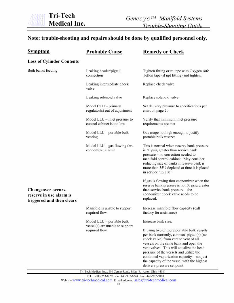
Note: trouble-shooting and repairs should be done by qualified personnel only.
Symptom
Cabinet Indicator Lights
No indicator lights on front panelilluminate when power is connected.
Red indicator lights are on but bothbanks are full
Left & right bank pressure LED’sflashing/blinking “ERR 000#”
Loss of Cylinder Contents
Audible or inaudible gas leakage(origin unknown)
Venting at relief valve
Probable Cause
Power input
Internal wiring disconnected
Circuit board defective
Master valve or cylinder valves onbank are closed
Pigtails are installed with checkvalves in wrong direction
Bank pressure is not sufficient forlogic board to place it in “In Use”or “Ready” status
Loose or disconnected or brokenwire, mis-connected wire, a badtransducer, a calibration problem oran over-pressure situation.
Leakage at manifold pipingconnections
Leakage thru manifold solenoidvent / relief
Regulator with bad seat
Leaking gauge
Regulator set too high
Overpressure due to failed regulatorseat
Regulator freeze-up (N2O or CO2)/ heater failure
Remedy or Check
Check electrical power supply
Check all wiring connections
Replace circuit board
Open valves SLOWLY
Close cylinders and re-install pigtails in proper flowdirection
Replace cylinders with full cylinders. Or, if usingportable bulk vessels, open pressure building valveon vessel or replace portable bulk vessel with higherdelivery pressure portable bulk vessel
Check wires for good and correct location connectionto circuit board (See ERROR CODES pg 15)If all wires are connected properly and locatedproperly – it may be necessary to replace atransducer.Contact Tri-Tech if pressure exceeds transducerrating + 5%. (2,600 psi or 525 psi).
Tighten, reseal or replace
Replace solenoid valve
Rebuild or replace regulator
Replace gauge
Set delivery pressure per specifications
Rebuild or replace regulator
Repair heater or add heater and consider addingadditional cylinders
Tri-Tech Medical Inc., 810 Center Road, Bldg.-E, Avon, Ohio 44011Tel. 1-800-253-8692 -or- 440-937-6244 Fax. 440-937-5060
Web site www.tri-techmedical.com E mail address: [email protected]
Tri-TechMedical Inc.
Genesys Manifold SystemsTrouble-Shooting Guide
Note: trouble-shooting and repairs should be done by qualified personnel only.
Symptom
Loss of Cylinder Contents
Both banks feeding
Changeover occurs,reserve in use alarm istriggered and then clears
Probable Cause
Leaking header/pigtailconnection
Leaking intermediate checkvalve
Leaking solenoid valve
Model CCU – primaryregulator(s) out of adjustment
Model LLU – inlet pressure tocontrol cabinet is too low
Model LLU – portable bulkventing
Model LLU – gas flowing thrueconomizer circuit
Manifold is unable to supportrequired flow
Model LLU – portable bulkvessel(s) are unable to supportrequired flow
Remedy or Check
Tighten fitting or re-tape with Oxygen safeTeflon tape (if npt fitting) and tighten.
Replace check valve
Replace solenoid valve
Set delivery pressure to specifications perchart on page 20
Verify that minimum inlet pressurerequirements are met
Gas usage not high enough to justifyportable bulk reserve
This is normal when reserve bank pressureis 50 psig greater than service bankpressure – no correction needed tomanifold control cabinet. May considerreducing size of banks if reserve bank ismore than 35% depleted at time it is placedin service “In Use”
If gas is flowing thru economizer when thereserve bank pressure is not 50 psig greaterthan service bank pressure – theeconomizer check valve needs to bereplaced.
Increase manifold flow capacity (callfactory for assistance)
Increase bank size.
If using two or more portable bulk vesselsper bank currently, connect pigtail(s) (nocheck valve) from vent to vent of allvessels on the same bank and open thevent valves. This will equalize the headpressure of the vessels and utilize thecombined vaporization capacity – not justthe capacity of the vessel with the highestdelivery pressure set point.
Tri-Tech Medical Inc., 810 Center Road, Bldg.-E, Avon, Ohio 44011Tel. 1-800-253-8692 -or- 440-937-6244 Fax. 440-937-5060
Web site www.tri-techmedical.com E mail address: [email protected]
Tri-TechMedical Inc.
Genesys Manifold SystemsAppendix A
Appendix A
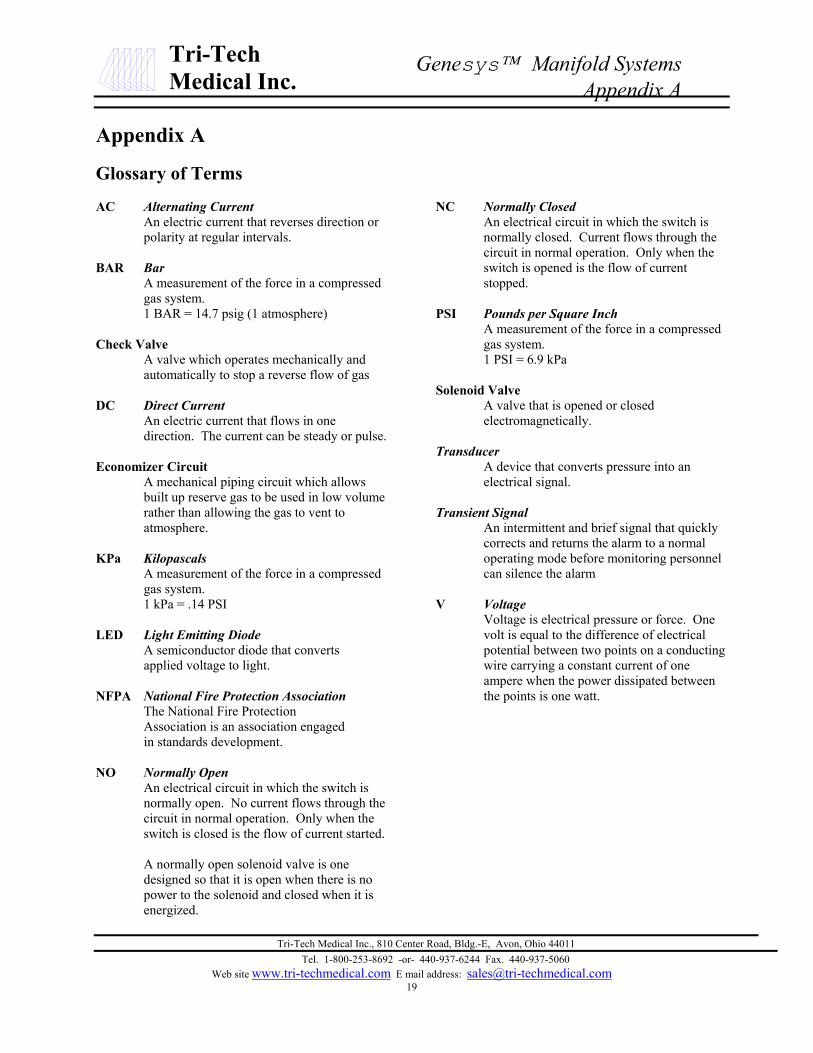
Glossary of Terms
AC Alternating CurrentAn electric current that reverses direction orpolarity at regular intervals.
BAR BarA measurement of the force in a compressedgas system.1 BAR = 14.7 psig (1 atmosphere)
Check ValveA valve which operates mechanically andautomatically to stop a reverse flow of gas
DC Direct CurrentAn electric current that flows in onedirection. The current can be steady or pulse.
Economizer CircuitA mechanical piping circuit which allowsbuilt up reserve gas to be used in low volumerather than allowing the gas to vent toatmosphere.
KPa KilopascalsA measurement of the force in a compressedgas system.1 kPa = .14 PSI
LED Light Emitting DiodeA semiconductor diode that convertsapplied voltage to light.
NFPA National Fire Protection AssociationThe National Fire ProtectionAssociation is an association engagedin standards development.
NO Normally OpenAn electrical circuit in which the switch isnormally open. No current flows through thecircuit in normal operation. Only when theswitch is closed is the flow of current started.
A normally open solenoid valve is onedesigned so that it is open when there is nopower to the solenoid and closed when it isenergized.
NC Normally ClosedAn electrical circuit in which the switch isnormally closed. Current flows through thecircuit in normal operation. Only when theswitch is opened is the flow of currentstopped.
PSI Pounds per Square InchA measurement of the force in a compressedgas system.1 PSI = 6.9 kPa
Solenoid ValveA valve that is opened or closedelectromagnetically.
TransducerA device that converts pressure into anelectrical signal.
Transient SignalAn intermittent and brief signal that quicklycorrects and returns the alarm to a normaloperating mode before monitoring personnelcan silence the alarm
V VoltageVoltage is electrical pressure or force. Onevolt is equal to the difference of electricalpotential between two points on a conductingwire carrying a constant current of oneampere when the power dissipated betweenthe points is one watt.

Tri-Tech Medical Inc., 810 Center Road, Bldg.-E, Avon, Ohio 44011Tel. 1-800-253-8692 -or- 440-937-6244 Fax. 440-937-5060
Web site www.tri-techmedical.com E mail address: [email protected]
Tri-TechMedical Inc.
Genesys Manifold SystemsAppendix B - Specifications
Appendix B – Manifold SpecificationsMaximum Inlet Pressure: Model CCU: 2,500 psig
Model LLU: 400 psig
Operating Ambient Temperature range:
Model CCU: 0 F (-18 C) to 120 F (49 C) all gases except N20 & CO220 F (-7 C) to 120 F (49 C) N2O & CO2
Model LLU -20 F ( -29 C) to 120 F (49 C)
Storage Temperature: -20C(-4F) to +85C(185F)
AC Input: 120 volts AC - 50-60 Hz
Input Fuse: 5 amp input AC line fuse protects the input wiring to power supply
Power Consumption: 45W (0.4 amps using 120 VAC) maximum without heaters245W (2.1 amps using 120 VAC) maximum with heaters
Pressure Measurement Accuracy:
0-100 PSIG transducer +/-1% - Line PressureOxygen, Nitrous Oxide, Medical Air, Carbon Dioxide
0-250PSIG transducer +/-1% - Line Pressure-Nitrogen
0 500 PSIG transducer +/-2% – Bank & Intermediate Pressures model LLU only
0 – 2,500 PSIG transducer +/-2% –Bank Pressures model CCU, Emergency Reserve Bank Pressure model LLU
Solenoid Valve: 24VDC – Normally Open (Valve opens when de-energized)
Dimensions
Control Cabinet: Dimensions excluding inlet & outlet fittings15 ¾” W x 24 ¾” H x 9 ¼” D
Dimensions including inlet & outlet fittings17 ¼” W x 27” H x 9 ¼” D
Line Pressure Transducers: Housing dimensions: 1.990W x 1.990H x 3.625 Lengthincluding inlet fittings
Primary Regulator Settings (CCU Models) Note: All settings done with full cylinder pressure and withslight gas flow thru the manifold. Primary regulator outlet pressure will vary with varying inlet pressures. (Theoutlet pressure will rise as the cylinder pressure decreases). All pressures shown in psig.
Normal Delivery Pressure (factory delivery pressure) Left Primary Regulator Set Point Right Primary Regulator Set Point
50 160 12080 260 220
190 260 220

Tri-Tech Medical Inc., 810 Center Road, Bldg.-E, Avon, Ohio 44011Tel. 1-800-253-8692 -or- 440-937-6244 Fax. 440-937-5060
Web site www.tri-techmedical.com E mail address: sales@tri-techmedica21
Tri-TechMedical Inc.
Genesys Manifold SystemAppendix C Piping Schematic – Model CCU
DISS demand valves –may be used to bleed linepressure during serviceand as emergency feedports for the facility
Ball valves Line pressure reliefvalve ½ F npt
Intermediate pressurerelief valves
Line pressure transducer – maybe installed downstream ofmanifold source valve toeliminate separate hi/lowpressure switch. Manifold PCBwill trigger master alarm hi/lowline pressure alarms
Line pressure regulator
Outlet – ½ F npt
Line pressure regulator
Intermediate pressure gauge
Check valve
Inlet pressure gauge
Inlet pressure transducer
e
Left bank primary regulatoroutlet pressure gauge
Left bank primary regulator
Solenoid valve
Line pressuregauge
Check valv
l.com
Intermediate reliefoutlet – ½ M npt
Inlet pressure gauge
Inlet pressure transducer
Right bank primary regulatoroutlet pressure gauge
Right bank primary regulator

Tri-Tech Medical Inc., 810 Center Road, Bldg.-E, Avon, Ohio 44011Tel. 1-800-253-8692 -or- 440-937-6244 Fax. 440-937-5060
Web site www.tri-techmedical.com E mail address: sales@tri-techmedica22
Tri-TechMedical Inc.
Genesys Manifold SystemsAppendix D Piping Schematic – Model LLU
DISS demand valves –may be used to bleed linepressure during serviceand as emergency feedports for the facility
Ball valves Line pressure reliefvalve ½ F npt
Line pressure transducer – maybe installed downstream ofmanifold source valve toeliminate separate hi/lowpressure switch. Manifold PCBwill trigger master alarm hi/lowline pressure alarms
Line pressure regulator
Outlet – ½ F npt
Line pressure regulator
Intermediate pressure gauge
Check valve
Inlet pressure gauge
Inlet pressure transducer
e
Solenoid valves
Line pressuregauge
Economizer circuit Economizer circuit
Check valv
l.com
Inlet pressure gauge
Inlet pressure transducer

Tri-Tech Medical Inc., 810 Center Road, Bldg.-E, Avon, Ohio 44011Tel. 1-800-253-8692 -or- 440-937-6244 Fax. 440-937-5060
Web site www.tri-techmedical.com E mail address: [email protected]
Tri-TechMedical Inc.
Genesys Manifold SystemsWiring Schematic – Model CCU

Tri-Tech Medical Inc., 810 Center Road, Bldg.-E, Avon, Ohio 44011Tel. 1-800-253-8692 -or- 440-937-6244 Fax. 440-937-5060
Web site www.tri-techmedical.com E mail address: [email protected]
Tri-TechMedical Inc.
Genesys Manifold SystemsWiring Schematic – Model LLU

Tri-Tech Medical Inc., 810 Center Road, Bldg.-E, Avon, Ohio 44011Tel. 1-800-253-8692 -or- 440-937-6244 Fax. 440-937-5060
Web site www.tri-techmedical.com E mail address: [email protected]
Tri-TechMedical Inc.
Genesys Manifold SystemsWiring Schematic – CCU with Heater

Tri-Tech Medical Inc., 810 Center Road, Bldg.-E, Avon, Ohio 44011Tel. 1-800-253-8692 -or- 440-937-6244 Fax. 440-937-5060
Web site www.tri-techmedical.com E mail address: [email protected]
Tri-TechMedical Inc.
Genesys Manifold SystemsAppendix H – Field Adjustments
Appendix HPressure Display Units of Measure
The digital pressure displays may be PSIG, kPa or BAR.If a selection is made at the time of order, your manifoldwill be set up to display the appropriate units. If noselection is made at the time of order, the unit will be setup to display in PSIG when shipped from Tri-TechMedical.
1. To change the units of measure a jumper has beenprovided (see photo – part # AA400-92) whichmust be installed on the circuit board. Beforeproceeding, remove the power from the manifold.
2. Remove the circuit board cover by loosening thefour screws, sliding the cover so the screws arecentered in the large part of the tear-drop shapedopening, then lift the cover off of the mountingposts.
3. Locate the set of jumper pins labeled JA1 on thelower left corner of the circuit board.
4. To change the display to kPa, install the jumperonto the top left & right pins of JA1. To changethe display to BAR, install the jumper onto thenext lower (from the top) left & right pins.
5. Replace the circuit board cover and restore power.The display will now reflect the units of measureselected (kPa or BAR). (Notes: all kPa units arex 10. Bar units are displayed with a one positiondecimal and decimal point.)
JA1 pin block with jumper installed to display BARJA1 pin block