installation operating manualacx advanced controller - 4 system controller acx advanced 1....
TRANSCRIPT
INSTALLATION & OPERATING MANUALACX Advanced Controller
Document Number: ACX_ADVANCED-MAN Rev. 2
UNIPOWER, LLC65 Industrial Park RdDunlap, TN 37327Phone: +1-954-346-2442Toll Free: 1-800-440-3504Web site: www.unipowerco.com
© 2019 UNIPOWER LLCAll Rights Reserved
P O W E R I N G T E C H N O L O G Y
P O W E R I N G T E C H N O L O G Y
Document Number: ACX_ADVANCED-MAN Rev. 2 acx-man-rev2-0719.indd
ACX Advanced Controller - 2
Contents1. Description .............................................................................................................................................4 1.1 Main Unit ..........................................................................................................................................5 1.2 Internal Connection Board ................................................................................................................5 1.3 External Connection Board ...............................................................................................................5 1.4 Extended Boards ...............................................................................................................................5 1.5 4x64 Multiplexer Board ....................................................................................................................52. Specifications ..........................................................................................................................................6 2.1 INPUT ...............................................................................................................................................6 2.2 INTERFACE .....................................................................................................................................6 2.2 BASIC FUNCTIONS .......................................................................................................................6 2.3 ALARMS ..........................................................................................................................................7 2.4 BATTERY MANAGEMENT ...........................................................................................................8 2.5 GENERAL ........................................................................................................................................83. Operation ...............................................................................................................................................9 3.1 Starting the Controller .....................................................................................................................9 3.2 Adding / Removing Modules and Units ...........................................................................................9 3.3 Controller Failure ..............................................................................................................................9 3.4 Control Buttons ...............................................................................................................................10 3.5 Display Icons ..................................................................................................................................104. Menu .....................................................................................................................................................12 4.1 Main Menu ......................................................................................................................................12 4.2 Show Alarms ...................................................................................................................................13 4.3 Show Messages ...............................................................................................................................13 4.4 Show Data .......................................................................................................................................13 4.5 Select / Adjust U1 - U4 ...................................................................................................................17 4.6 Adjust Limits ..................................................................................................................................18 4.7 Miscellaneous .................................................................................................................................26 4.8 Energy Saving Mode.......................................................................................................................285. ControllerAlarms/Messages ............................................................................................................316. ConnectiontoControllerviaPowCom™software ..........................................................................34 6.1 Connecting to the Controller via USB - Direct Communication ....................................................34 6.2 Connecting to Controller via a Network .........................................................................................357. ConnectingtotheControllerviatheWebInterface ........................................................................37 7.1 Connection ......................................................................................................................................37 7.2 Web Interface Menu ........................................................................................................................388. SNMP ....................................................................................................................................................48 8.1 MIB .................................................................................................................................................48 8.2 SNMPNotifications ........................................................................................................................51 8.3 SNMPv3 ..........................................................................................................................................519. ControllerDataLogging-microSDCard .........................................................................................54APPENDIXA-Upgradingthefirmware ....................................................................................................56APPENDIXB- Adding a new language to the Controller .........................................................................61APPENDIXC- Two-Stage Customizable Charging Algorithm ................................................................63PRODUCTSUPPORT ..............................................................................................................................65
REV DESCRIPTION CHK’d&APPR’d/DATE2 PCO# 45394 MM / 07-31-19
P O W E R I N G T E C H N O L O G Y
Document Number: ACX_ADVANCED-MAN Rev. 2 acx-man-rev2-0719.indd
ACX Advanced Controller - 3
FIGURESFigure 1 - Controller Features ..........................................................................................................4Figure 2 - Display Icons .................................................................................................................10Figure 3 - Main Menu ....................................................................................................................12Figure 4 - Show Data .....................................................................................................................13Figure 5a - Show Module Data ......................................................................................................14Figure 5b - Show Module Data with 4x64 Multiplexer .................................................................14Figure 6 - Show Unit Data .............................................................................................................15Figure 7 - Show SLI Data ..............................................................................................................16Figure 8 - External Measurements .................................................................................................16Figure 9 - Symmetry Measurements ..............................................................................................17Figure 10 - Adjust Limits ...............................................................................................................18Figure 11 - Boost charging .............................................................................................................20Figure 12a - Menu Tree part 1 .......................................................................................................29Figure 12b - Menu Tree part 2 .......................................................................................................30Figure 13 - USB Cable ...................................................................................................................34Figure 14 - Communication ...........................................................................................................34Figure 15 - Network .......................................................................................................................35Figure 16 - Password .....................................................................................................................36Figure 17 - Connect .......................................................................................................................38Figure 18 - Web Interface Overview ..............................................................................................39Figure19a-WebInterfaceRectifier ..............................................................................................40Figure19b-WebInterfaceRectifierwith4x64MultiplexerBoard ..............................................40Figure 20 - Web Interface SLI .......................................................................................................41Figure 21 - Web Interface Units .....................................................................................................41Figure 22 - Web Interface Battery ..................................................................................................42Figure 23 - Web Interface Controller .............................................................................................42Figure 24 - Web Interface External Measurements........................................................................42Figure25-WebInterfaceAdmin.Configuration ..........................................................................43Figure26-WebInterfaceConfiguration|System .........................................................................44Figure27-WebInterfaceConfiguration|Test ..............................................................................44Figure28-WebInterfaceConfiguration|Alarm ..........................................................................45Figure29-WebInterfaceConfiguration|Network ......................................................................45Figure30-WebInterfaceConfiguration|Limits ..........................................................................46Figure 31 - SNMPv3 security parameters values in table view .....................................................52Figure 32 - SNMPv3 initialization displayed on the web page .....................................................53
TABLESTable 1 - Alarm Data ......................................................................................................................49Table 2 - Alarm Data ......................................................................................................................55
P O W E R I N G T E C H N O L O G Y
Document Number: ACX_ADVANCED-MAN Rev. 2 acx-man-rev2-0719.indd
ACX Advanced Controller - 4
System Controller ACX Advanced
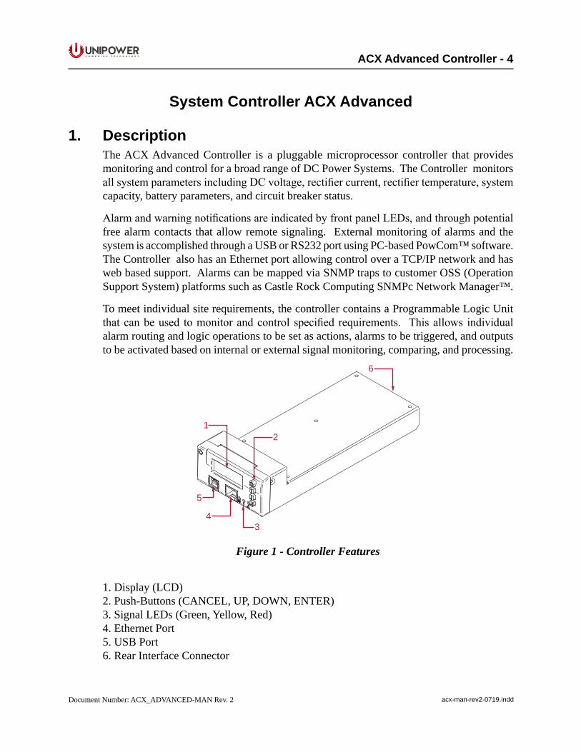
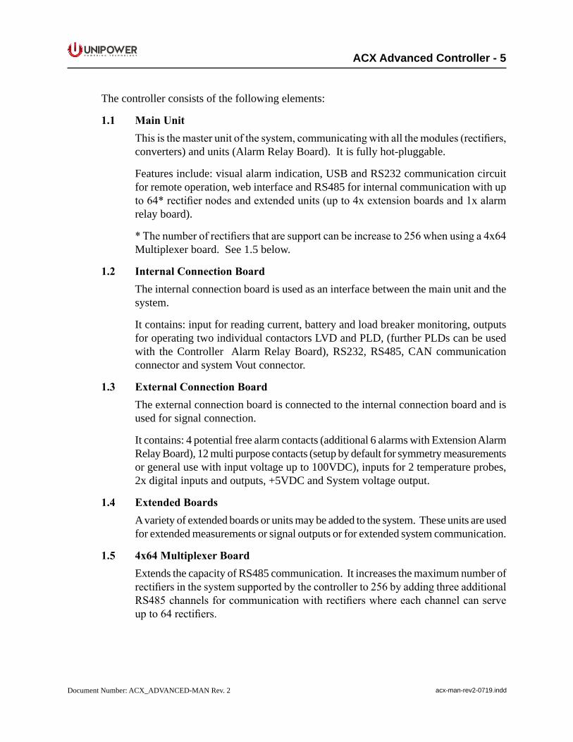
1. DescriptionThe ACX Advanced Controller is a pluggable microprocessor controller that provides monitoring and control for a broad range of DC Power Systems. The Controller monitors allsystemparametersincludingDCvoltage,rectifiercurrent,rectifiertemperature,systemcapacity, battery parameters, and circuit breaker status.
AlarmandwarningnotificationsareindicatedbyfrontpanelLEDs,andthroughpotentialfree alarm contacts that allow remote signaling. External monitoring of alarms and the system is accomplished through a USB or RS232 port using PC-based PowCom™ software. The Controller also has an Ethernet port allowing control over a TCP/IP network and has web based support. Alarms can be mapped via SNMP traps to customer OSS (Operation Support System) platforms such as Castle Rock Computing SNMPc Network Manager™.
To meet individual site requirements, the controller contains a Programmable Logic Unit thatcanbeused tomonitorandcontrol specified requirements. Thisallows individualalarm routing and logic operations to be set as actions, alarms to be triggered, and outputs to be activated based on internal or external signal monitoring, comparing, and processing.
12
34
5
6
Figure 1 - Controller Features
1. Display (LCD)2. Push-Buttons (CANCEL, UP, DOWN, ENTER)3. Signal LEDs (Green, Yellow, Red)4. Ethernet Port5. USB Port6. Rear Interface Connector
P O W E R I N G T E C H N O L O G Y
Document Number: ACX_ADVANCED-MAN Rev. 2 acx-man-rev2-0719.indd
ACX Advanced Controller - 5
The controller consists of the following elements:
1.1 MainUnitThisisthemasterunitofthesystem,communicatingwithallthemodules(rectifiers,converters) and units (Alarm Relay Board). It is fully hot-pluggable.
Features include: visual alarm indication, USB and RS232 communication circuit for remote operation, web interface and RS485 for internal communication with up to64*rectifiernodesandextendedunits(upto4xextensionboardsand1xalarmrelay board).
*Thenumberofrectifiersthataresupportcanbeincreaseto256whenusinga4x64Multiplexer board. See 1.5 below.
1.2 InternalConnectionBoardThe internal connection board is used as an interface between the main unit and the system.
It contains: input for reading current, battery and load breaker monitoring, outputs for operating two individual contactors LVD and PLD, (further PLDs can be used with the Controller Alarm Relay Board), RS232, RS485, CAN communication connector and system Vout connector.
1.3 ExternalConnectionBoardThe external connection board is connected to the internal connection board and is used for signal connection.
It contains: 4 potential free alarm contacts (additional 6 alarms with Extension Alarm Relay Board), 12 multi purpose contacts (setup by default for symmetry measurements or general use with input voltage up to 100VDC), inputs for 2 temperature probes, 2x digital inputs and outputs, +5VDC and System voltage output.
1.4 ExtendedBoardsA variety of extended boards or units may be added to the system. These units are used for extended measurements or signal outputs or for extended system communication.
1.5 4x64MultiplexerBoardExtends the capacity of RS485 communication. It increases the maximum number of rectifiersinthesystemsupportedbythecontrollerto256byaddingthreeadditionalRS485channelsforcommunicationwithrectifierswhereeachchannelcanserveupto64rectifiers.
P O W E R I N G T E C H N O L O G Y
Document Number: ACX_ADVANCED-MAN Rev. 2 acx-man-rev2-0719.indd
ACX Advanced Controller - 6
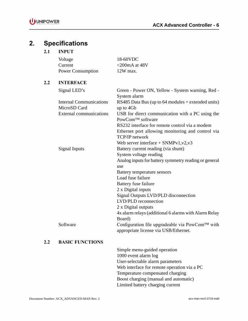
2. Specifications2.1 INPUT Voltage 18-60VDC Current <200mA at 48V Power Consumption 12W max.
2.2 INTERFACE Signal LED’s Green - Power ON, Yellow - System warning, Red -
System alarm Internal Communications RS485 Data Bus (up to 64 modules + extended units) MicroSD Card up to 4Gb External communications USB for direct communication with a PC using the
PowCom™ software RS232 interface for remote control via a modem Ethernet port allowing monitoring and control via
TCP/IP network Web server interface + SNMPv1,v2,v3 Signal Inputs Battery current reading (via shunt) System voltage reading Analog inputs for battery symmetry reading or general
use Battery temperature sensors Load fuse failure Battery fuse failure 2 x Digital inputs Signal Outputs LVD/PLD disconnection LVD/PLD reconnection 2 x Digital outputs 4x alarm relays (additional 6 alarms with Alarm Relay
Board) Software ConfigurationfileupgradeableviaPowCom™with
appropriate license via USB/Ethernet.
2.2 BASICFUNCTIONS Simple menu-guided operation 1000 event alarm log User-selectable alarm parameters Web interface for remote operation via a PC Temperature compensated charging Boost charging (manual and automatic) Limited battery charging current
P O W E R I N G T E C H N O L O G Y
Document Number: ACX_ADVANCED-MAN Rev. 2 acx-man-rev2-0719.indd
ACX Advanced Controller - 7
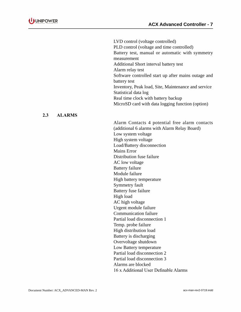
LVD control (voltage controlled) PLD control (voltage and time controlled) Battery test, manual or automatic with symmetry
measurement Additional Short interval battery test Alarm relay test Software controlled start up after mains outage and
battery test Inventory, Peak load, Site, Maintenance and service Statistical data log Real time clock with battery backup MicroSD card with data logging function (option)
2.3 ALARMS Alarm Contacts 4 potential free alarm contacts
(additional 6 alarms with Alarm Relay Board) Low system voltage High system voltage Load/Battery disconnection Mains Error Distribution fuse failure AC low voltage Battery failure Module failure High battery temperature Symmetry fault Battery fuse failure High load AC high voltage Urgent module failure Communication failure Partial load disconnection 1 Temp. probe failure High distribution load Battery is discharging Overvoltage shutdown Low Battery temperature Partial load disconnection 2 Partial load disconnection 3 Alarms are blocked 16xAdditionalUserDefinableAlarms
P O W E R I N G T E C H N O L O G Y
Document Number: ACX_ADVANCED-MAN Rev. 2 acx-man-rev2-0719.indd
ACX Advanced Controller - 8
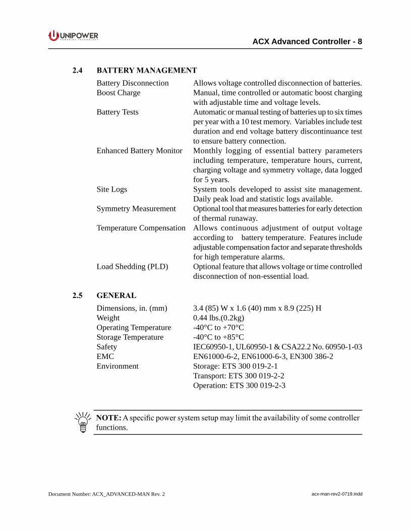
2.4 BATTERYMANAGEMENT Battery Disconnection Allows voltage controlled disconnection of batteries. Boost Charge Manual, time controlled or automatic boost charging
with adjustable time and voltage levels. Battery Tests Automatic or manual testing of batteries up to six times
per year with a 10 test memory. Variables include test duration and end voltage battery discontinuance test to ensure battery connection.
Enhanced Battery Monitor Monthly logging of essential battery parameters including temperature, temperature hours, current, charging voltage and symmetry voltage, data logged for 5 years.
Site Logs System tools developed to assist site management. Daily peak load and statistic logs available.
Symmetry Measurement Optional tool that measures batteries for early detection of thermal runaway.
Temperature Compensation Allows continuous adjustment of output voltage according to battery temperature. Features include adjustable compensation factor and separate thresholds for high temperature alarms.
Load Shedding (PLD) Optional feature that allows voltage or time controlled disconnection of non-essential load.
2.5 GENERAL Dimensions, in. (mm) 3.4 (85) W x 1.6 (40) mm x 8.9 (225) H Weight 0.44 lbs.(0.2kg) Operating Temperature -40°C to +70°C Storage Temperature -40°C to +85°C Safety IEC60950-1, UL60950-1 & CSA22.2 No. 60950-1-03 EMC EN61000-6-2, EN61000-6-3, EN300 386-2 Environment Storage: ETS 300 019-2-1 Transport: ETS 300 019-2-2 Operation: ETS 300 019-2-3
NOTE:Aspecificpowersystemsetupmaylimittheavailabilityofsomecontrollerfunctions.
P O W E R I N G T E C H N O L O G Y
Document Number: ACX_ADVANCED-MAN Rev. 2 acx-man-rev2-0719.indd
ACX Advanced Controller - 9
3. OperationThis section contains a basic description of the Controller functions.
3.1 StartingtheController When the controller is turned ON it takes approximately 5 seconds to analyze the
system and test all addresses for connected modules and units. The green LED on the display starts blinking. No alarm signals are given during this period.
WhentheControlleridentifiesamoduleoraunit,itisautomaticallyaddedtoitsinventory. Modules and units remain in the system memory until a master reset or reconfigurationisperformed.
3.2 Adding/RemovingModulesandUnits
AddingModulesandUnits
The Controller constantly scans for new modules and units. When, for example, a rectifierisaddedtothesystemitremainsinvisibleuntildetectedbytheController.
Ittakessometimefortherectifiertoreachthevalueofthesystemvoltageandsharecurrentwithotherrectifiers.Untilthentherectifiercurrentvalueis0A.
RemovingModulesandUnits
When a module or a unit is removed from the system a communication error alarm is generated.
Toremovetheerrormessagepressthe“Reconfigure”buttonintheInventorywindowin the PowCom™ software (see the PowCom Instruction Manual). It can be also done via the front panel, see section 4.7.14 - Accept Removed Parts.
Reconfiguration removes all non-communicatingmodules and units from theinventory.
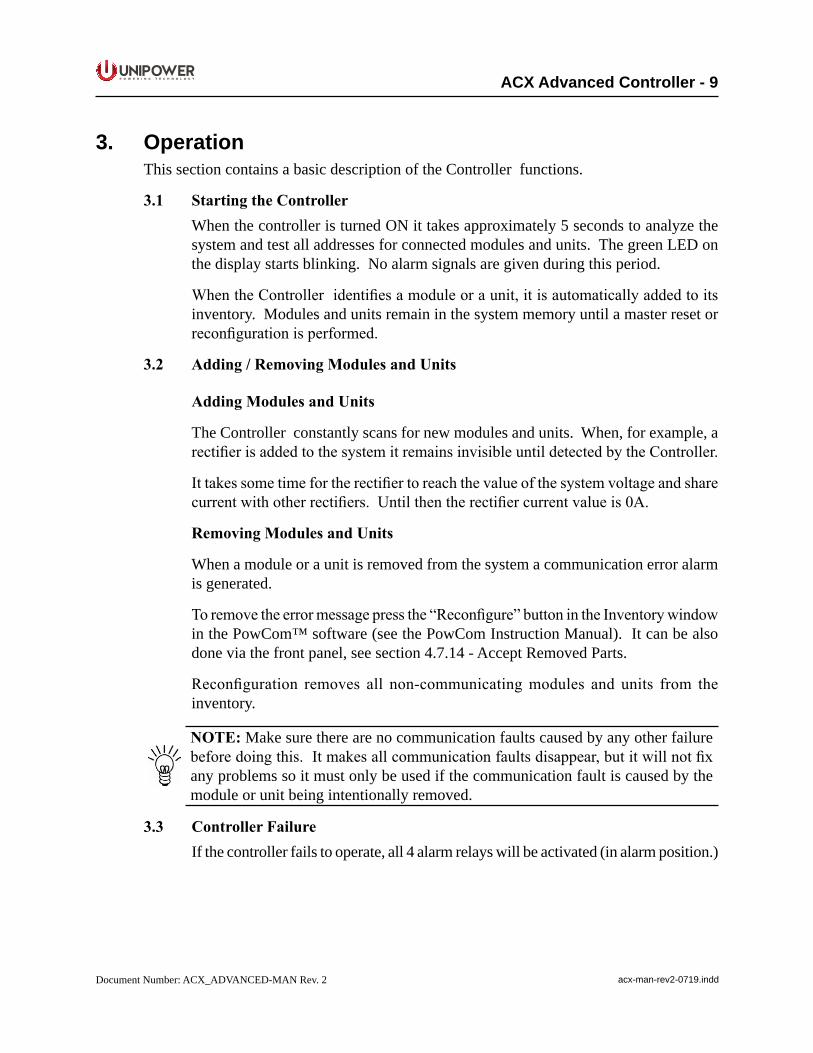
NOTE: Make sure there are no communication faults caused by any other failure beforedoingthis.Itmakesallcommunicationfaultsdisappear,butitwillnotfixany problems so it must only be used if the communication fault is caused by the module or unit being intentionally removed.
3.3 ControllerFailure If the controller fails to operate, all 4 alarm relays will be activated (in alarm position.)
P O W E R I N G T E C H N O L O G Y
Document Number: ACX_ADVANCED-MAN Rev. 2 acx-man-rev2-0719.indd
ACX Advanced Controller - 10
3.4 ControlButtonsTo browse the controller menu, 4 push-buttons are used to scroll and select.
• CANCEL - is used to cancel the current selection on the menu hierarchy. When pressed the menu returns one step back.
• UPARROW - is used to move up in the menu hierarchy, to select options or adjust limits.
• DOWNARROW - is used to move down in the menu hierarchy, to select options or adjust limits
• ENTER-isusedtoselectandconfirmanoptionortomoveforwardonelevelin the menu hierarchy.
If the controller is left unattended the display returns to the Main menu automatically after 2 minutes.
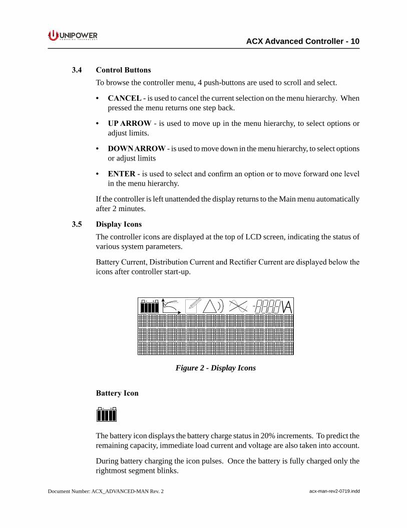
3.5 DisplayIconsThe controller icons are displayed at the top of LCD screen, indicating the status of various system parameters.
BatteryCurrent,DistributionCurrentandRectifierCurrentaredisplayedbelowtheicons after controller start-up.
+-
Figure 2 - Display Icons
BatteryIcon
+-
The battery icon displays the battery charge status in 20% increments. To predict the remaining capacity, immediate load current and voltage are also taken into account.
During battery charging the icon pulses. Once the battery is fully charged only the rightmost segment blinks.
P O W E R I N G T E C H N O L O G Y
Document Number: ACX_ADVANCED-MAN Rev. 2 acx-man-rev2-0719.indd
ACX Advanced Controller - 11
Whenstartingthesystemforthefirsttimeittakessometimebeforethebatteryiconis fully operational and displays correctly. The battery capacity must be set correctly (AdjustLimits→Batterysettings→BatteryCapacity).IftheBatterycapacityisset to 0 (zero) the icon is not shown.
NOTE: The battery charge status may be incorrect if the battery is malfunctioning.
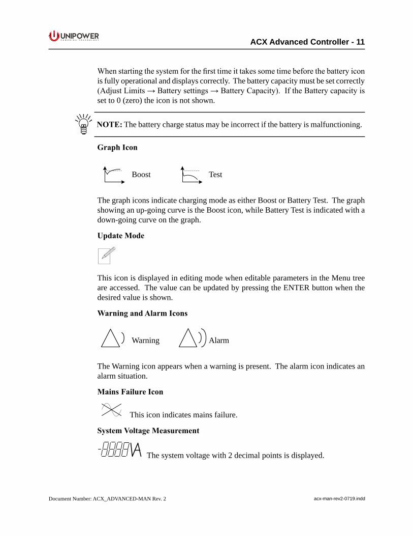
GraphIcon
Boost Test
The graph icons indicate charging mode as either Boost or Battery Test. The graph showing an up-going curve is the Boost icon, while Battery Test is indicated with a down-going curve on the graph.
UpdateMode
This icon is displayed in editing mode when editable parameters in the Menu tree are accessed. The value can be updated by pressing the ENTER button when the desired value is shown.
WarningandAlarmIcons
Warning Alarm
The Warning icon appears when a warning is present. The alarm icon indicates an alarm situation.
MainsFailureIcon
This icon indicates mains failure.
SystemVoltageMeasurement
The system voltage with 2 decimal points is displayed.
P O W E R I N G T E C H N O L O G Y
Document Number: ACX_ADVANCED-MAN Rev. 2 acx-man-rev2-0719.indd
ACX Advanced Controller - 12
4. MenuThecontrollerdisplayisconfiguredintoasetofscrollablemenusthatprovideaneasywaytofindtheinformationorsettingsrequired.Theinformationbelowdescribeshowtonavigatethrough the controller display and explains various menu options and system behavior.
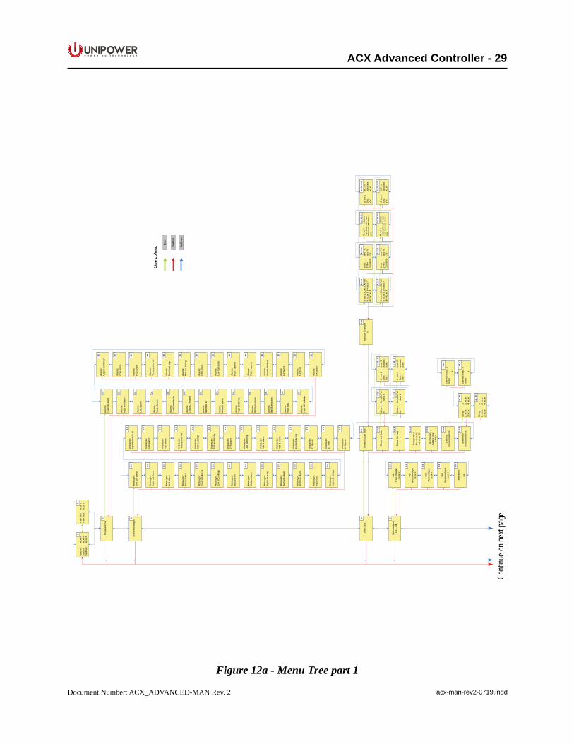
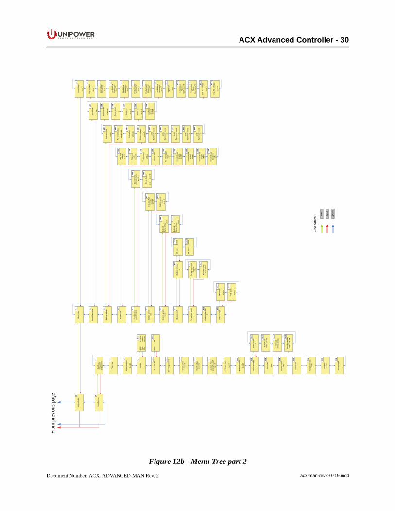
NOTE: See full Controller Menu Tree on pages 31 & 32..
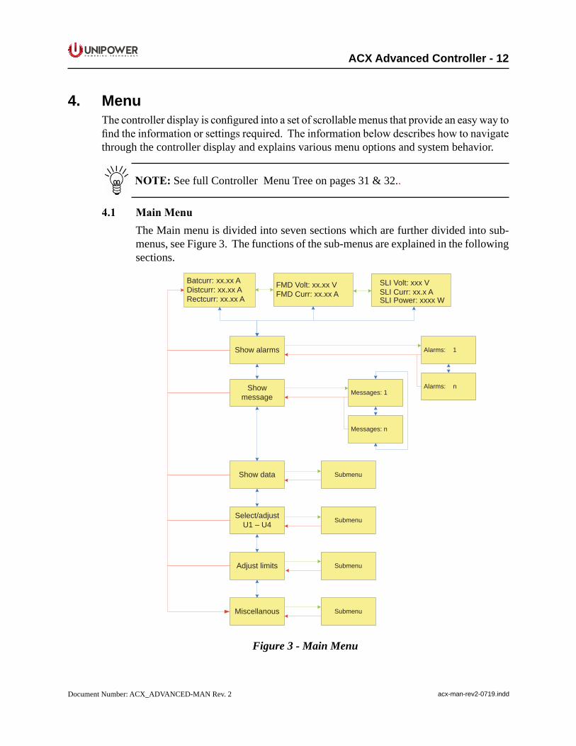
4.1 MainMenuThe Main menu is divided into seven sections which are further divided into sub-menus, see Figure 3. The functions of the sub-menus are explained in the following sections.
Show alarms
FMD Volt: xx.xx VFMD Curr: xx.xx A
Batcurr: xx.xx ADistcurr: xx.xx ARectcurr: xx.xx A
Showmessage
Show data
Select/adjustU1 – U4
Adjust limits
Miscellanous
Alarms: 1
Alarms: nMessages: 1
Messages: n
Submenu
Submenu
Submenu
Submenu
SLI Volt: xxx VSLI Curr: xx.x ASLI Power xx W: xx
Figure 3 - Main Menu
P O W E R I N G T E C H N O L O G Y
Document Number: ACX_ADVANCED-MAN Rev. 2 acx-man-rev2-0719.indd
ACX Advanced Controller - 13
4.2 ShowAlarms This window displays the current alarm status. If there are several concurrent alarms
2smalltriangles(▼▲)appearintheupperrightcorner.Usethearrowkeystoscrollthrough the alarms. Any removed alarm disappears from the alarm list automatically while any new one is added to the alarm menu immediately. Battery failure and symmetry failure alarms need to be reset manually by pressing and holding ENTER for a short time.
4.3 ShowMessages This item displays any messages. If there are multiple concurrent messages, scroll
down to view all of them. New or removed messages are updated on the menu immediately.
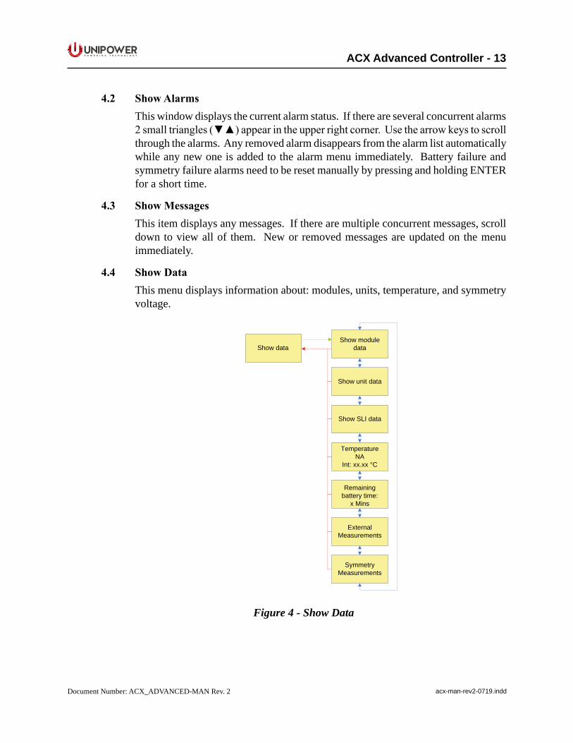
4.4 ShowData This menu displays information about: modules, units, temperature, and symmetry
voltage.
Show module data
Show unit data
Show SLI data
TemperatureNA
Int: xx.xx °C
Remainingbattery time:
x Mins
ExternalMeasurements
SymmetryMeasurements
Show data
Figure 4 - Show Data
P O W E R I N G T E C H N O L O G Y
Document Number: ACX_ADVANCED-MAN Rev. 2 acx-man-rev2-0719.indd
ACX Advanced Controller - 14
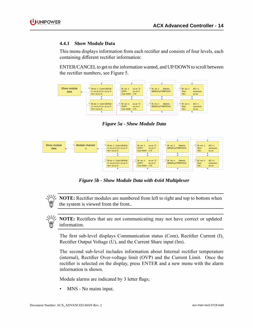
4.4.1 ShowModuleDataThismenudisplaysinformationfromeachrectifierandconsistsoffourlevels,eachcontainingdifferentrectifierinformation:
ENTER/CANCEL to get to the information wanted, and UP/DOWN to scroll between therectifiernumbers,seeFigure5.
Show module data
M.no: 1 Com:Ok/FailI= xx.xx A U= xx.xx VIm= xx.xx A
M.no: n Com:Ok/FailI= xx.xx A U= xx.xx VIm= xx.xx A
M. no: 1 xx.xx °COVP= xx.xx VCurr limit= x %
M. no: n xx.xx °COVP= xx.xx VCurr limit= x %
M. no: 1 AlarmsMNS/Cur/TMP/OVS
M. no: n AlarmsMNS/Cur/TMP/OVS
M. no: 1 AC= xSno: xxxxxxxxVer.: xx.xx
M. no: n AC= xSno: xxxxxxxxVer.: xx.xx
Figure 5a - Show Module Data
Module channel x
M.no: 1 Com:Ok/FailI= xx.xx A U= xx.xx VIm= xx.xx A
M.no: n Com:Ok/FailI= xx.xx A U= xx.xx VIm= xx.xx A
M. no: 1 xx.xx °COVP= xx.xx VCurr limit= x %
M. no: n xx.xx °COVP= xx.xx VCurr limit= x %
M. no: 1 AlarmsMNS/Cur/TMP/OVS
M. no: n AlarmsMNS/Cur/TMP/OVS
M. no: 1 AC= xSno: xxxxxxxxVer.: xx.xx
M. no: n AC= xSno: xxxxxxxxVer.: xx.xx
Show module data
Figure 5b - Show Module Data with 4x64 Multiplexer
NOTE:Rectifiermodulesarenumberedfromlefttorightandtoptobottomwhenthe system is viewed from the front..
NOTE:Rectifiers thatarenotcommunicatingmaynothavecorrectorupdatedinformation.
Thefirst sub-level displaysCommunication status (Com),RectifierCurrent (I),RectifierOutputVoltage(U),andtheCurrentShareinput(Im).
The second sub-level includes information about Internal rectifier temperature(internal),RectifierOver-voltage limit (OVP) and theCurrentLimit. Once therectifierisselectedonthedisplay,pressENTERandanewmenuwiththealarminformation is shown.
Modulealarmsareindicatedby3letterflags;
• MNS - No mains input.
P O W E R I N G T E C H N O L O G Y
Document Number: ACX_ADVANCED-MAN Rev. 2 acx-man-rev2-0719.indd
ACX Advanced Controller - 15
• LOW-Outputvoltagelow(dependsonrectifiertype).
• OFF - No operation, caused by mains failure, other failure or when module is turnedoffmanuallyorautomatically.
• OVS - Overvoltage shutdown.
• FAN - Fan failure. The consequences of a fan failure depend on the type of rectifier.Pleaseseetherectifierchapterofyoursystemmanualfordetails.
• CUR-Currentsharingfault.Rectifieroutputcurrentdeviatestoomuchfromthe average value.
• TMP - Temperature is high. This alarm must be reset manually.
Thefourthsub-leveldisplaysACinputvoltage(ifavailable),Rectifierserialnumber(ifavailable)andrectifiersoftwareversion(ifavailable).
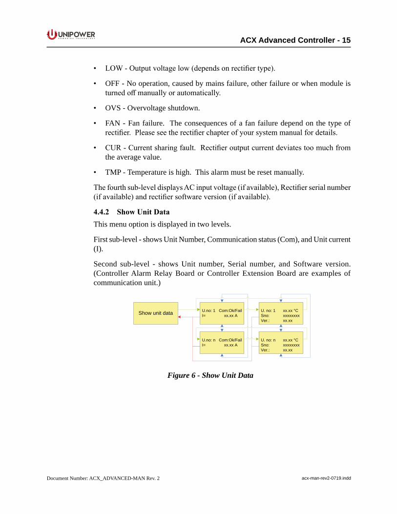
4.4.2 ShowUnitDataThis menu option is displayed in two levels.
First sub-level - shows Unit Number, Communication status (Com), and Unit current (I).
Second sub-level - shows Unit number, Serial number, and Software version. (Controller Alarm Relay Board or Controller Extension Board are examples of communication unit.)
Show unit data U.no: 1 Com:Ok/FailI= xx.xx A
U.no: n Com:Ok/FailI= xx.xx A
U. no: 1 xx.xx °CSno: xxxxxxxxVer.: xx.xx
U. no: n xx.xx °CSno: xxxxxxxxVer.: xx.xx
Figure 6 - Show Unit Data
P O W E R I N G T E C H N O L O G Y
Document Number: ACX_ADVANCED-MAN Rev. 2 acx-man-rev2-0719.indd
ACX Advanced Controller - 16
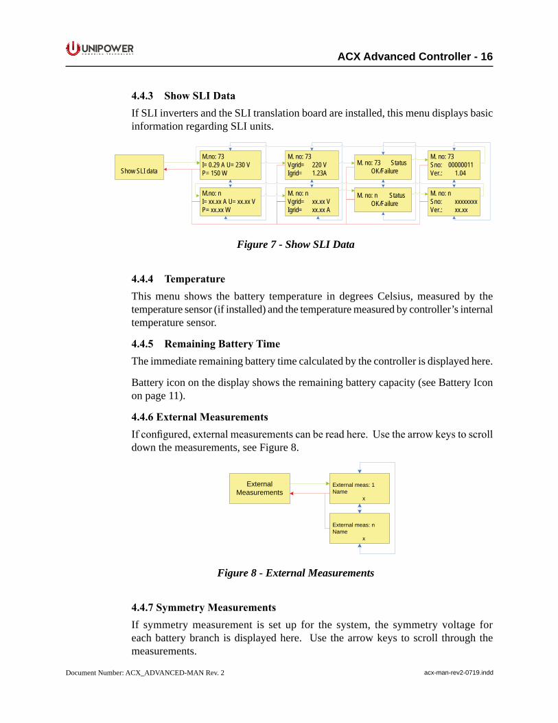
4.4.3 ShowSLIDataIf SLI inverters and the SLI translation board are installed, this menu displays basic information regarding SLI units.
Show SLI data
M.no: 73I= 0.29 A U= 230 VP= 150 W
M.no: nI= xx.xx A U= xx.xx VP= xx.xx W
M. no: 73Vgrid= 220 VIgrid= 1.23A
M. no: nVgrid= xx.xx VIgrid= xx.xx A
M. no: 73 Status OK/Failure
M. no: n Status OK/Failure
M. no: 73Sno: 00000011Ver.: 1.04
M. no: nSno: xxxxxxxxVer.: xx.xx
Figure 7 - Show SLI Data
4.4.4 TemperatureThis menu shows the battery temperature in degrees Celsius, measured by the temperature sensor (if installed) and the temperature measured by controller’s internal temperature sensor.
4.4.5 RemainingBatteryTimeThe immediate remaining battery time calculated by the controller is displayed here.
Battery icon on the display shows the remaining battery capacity (see Battery Icon on page 11).
4.4.6ExternalMeasurementsIfconfigured,externalmeasurementscanbereadhere.Usethearrowkeystoscrolldown the measurements, see Figure 8.
ExternalMeasurements
External meas: 1Name
x
External meas: nName
x
Figure 8 - External Measurements
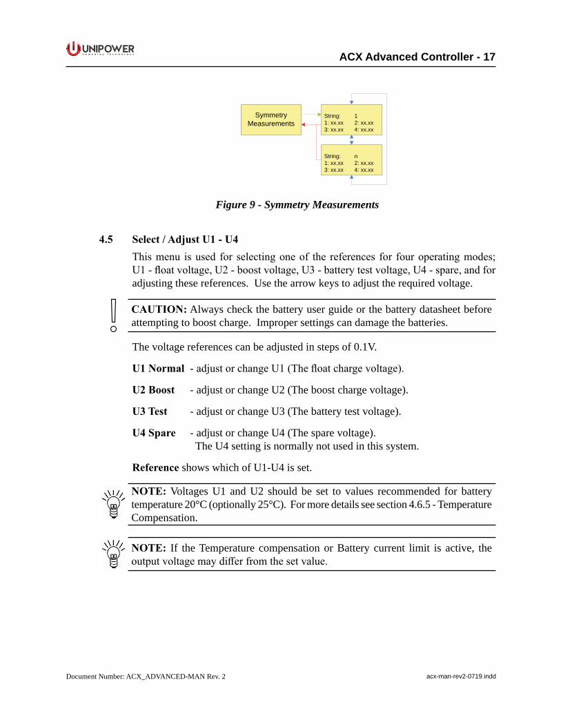
4.4.7SymmetryMeasurementsIf symmetry measurement is set up for the system, the symmetry voltage for each battery branch is displayed here. Use the arrow keys to scroll through the measurements.
P O W E R I N G T E C H N O L O G Y
Document Number: ACX_ADVANCED-MAN Rev. 2 acx-man-rev2-0719.indd
ACX Advanced Controller - 17
SymmetryMeasurements
String: 11: xx.xx 2: xx.xx3: xx.xx 4: xx.xx
String: n1: xx.xx 2: xx.xx3: xx.xx 4: xx.xx
Figure 9 - Symmetry Measurements
4.5 Select/AdjustU1-U4Thismenu isused for selectingoneof the references for fouroperatingmodes;U1-floatvoltage,U2-boostvoltage,U3-batterytestvoltage,U4-spare,andforadjusting these references. Use the arrow keys to adjust the required voltage.
CAUTION: Always check the battery user guide or the battery datasheet before attempting to boost charge. Improper settings can damage the batteries.
The voltage references can be adjusted in steps of 0.1V.
U1Normal -adjustorchangeU1(Thefloatchargevoltage).
U2Boost - adjust or change U2 (The boost charge voltage).
U3Test - adjust or change U3 (The battery test voltage).
U4Spare - adjust or change U4 (The spare voltage). The U4 setting is normally not used in this system.
Referenceshows which of U1-U4 is set.
NOTE: Voltages U1 and U2 should be set to values recommended for battery temperature 20°C (optionally 25°C). For more details see section 4.6.5 - Temperature Compensation.
NOTE: If the Temperature compensation or Battery current limit is active, the outputvoltagemaydifferfromthesetvalue.
P O W E R I N G T E C H N O L O G Y
Document Number: ACX_ADVANCED-MAN Rev. 2 acx-man-rev2-0719.indd
ACX Advanced Controller - 18
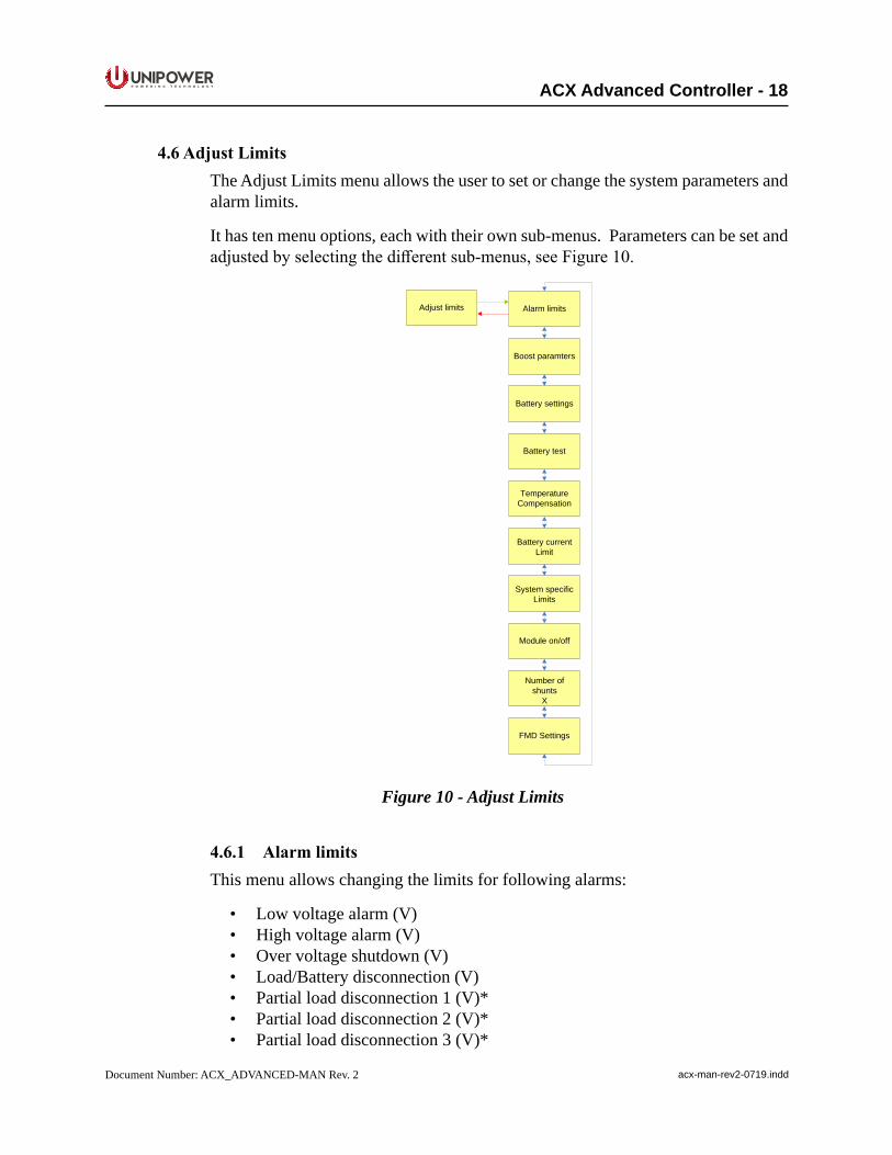
4.6AdjustLimitsThe Adjust Limits menu allows the user to set or change the system parameters and alarm limits.
It has ten menu options, each with their own sub-menus. Parameters can be set and adjustedbyselectingthedifferentsub-menus,seeFigure10.
Adjust limits Alarm limits
Boost paramters
Battery settings
Battery test
TemperatureCompensation
Battery currentLimit
System specificLimits
Module on/off
Number of shunts
X
FMD Settings
Figure 10 - Adjust Limits
4.6.1 AlarmlimitsThis menu allows changing the limits for following alarms:
• Low voltage alarm (V)• High voltage alarm (V)• Over voltage shutdown (V)• Load/Battery disconnection (V)• Partial load disconnection 1 (V)*• Partial load disconnection 2 (V)*• Partial load disconnection 3 (V)*
P O W E R I N G T E C H N O L O G Y
Document Number: ACX_ADVANCED-MAN Rev. 2 acx-man-rev2-0719.indd
ACX Advanced Controller - 19
• Load/Battery reconnection (V)• High load (%)• High temperature alarm (°C)• Low temperature alarm (°C)• Low AC voltage (V)• High AC voltage (V)
*Partialloaddisconnection,ifconfiguredintheConfigWizard,canalsobecontrolledby time. The time counter starts counting after AC mains failure. Then the value appears in minutes [min] instead of Volts [V].
NOTE: The High Load alarm is activated when the load current exceeds the capacity of the installed modules multiplied by the high load limit. This is an indication that thesystemrequiresincreasedrectifiercapacity.
CAUTION: Adjusting the controller alarm and limit settings may have serious impactonsystembehavior.Onlyqualifiedinstallersshouldadjusttheselimits.
To change these limits use the arrow keys and press ENTER to select. See Appendix B,Configurationofyoursystemmanualforthedefaultsettings.
4.6.2 BoostParametersThis menu contains the limits for boost charging control. The following parameters can be set:
• Boost time (Hours)• Boost interval (Weeks)• Boost factor (-)• Boost t1 (V)• Boost t2 (V)• AutoboostEnable(On/Off)
Boost charging can be activated by three methods:
1. Manual boost charging - can be activated manually by selecting U2 via the controller front panel (Select/Adjust U1-U4 > Reference > U2) or via PowCom™ software (Adjust limits window).ReturntofloatchargemanuallybychoosingU1,orautomatically,afterapre-settime.
2. Periodic boost charging - after a pre-set period boost charging will be automatically activated for a pre-set time. The interval and boost time should be programmed (for example 4 hours every 3rd week).
P O W E R I N G T E C H N O L O G Y
Document Number: ACX_ADVANCED-MAN Rev. 2 acx-man-rev2-0719.indd
ACX Advanced Controller - 20
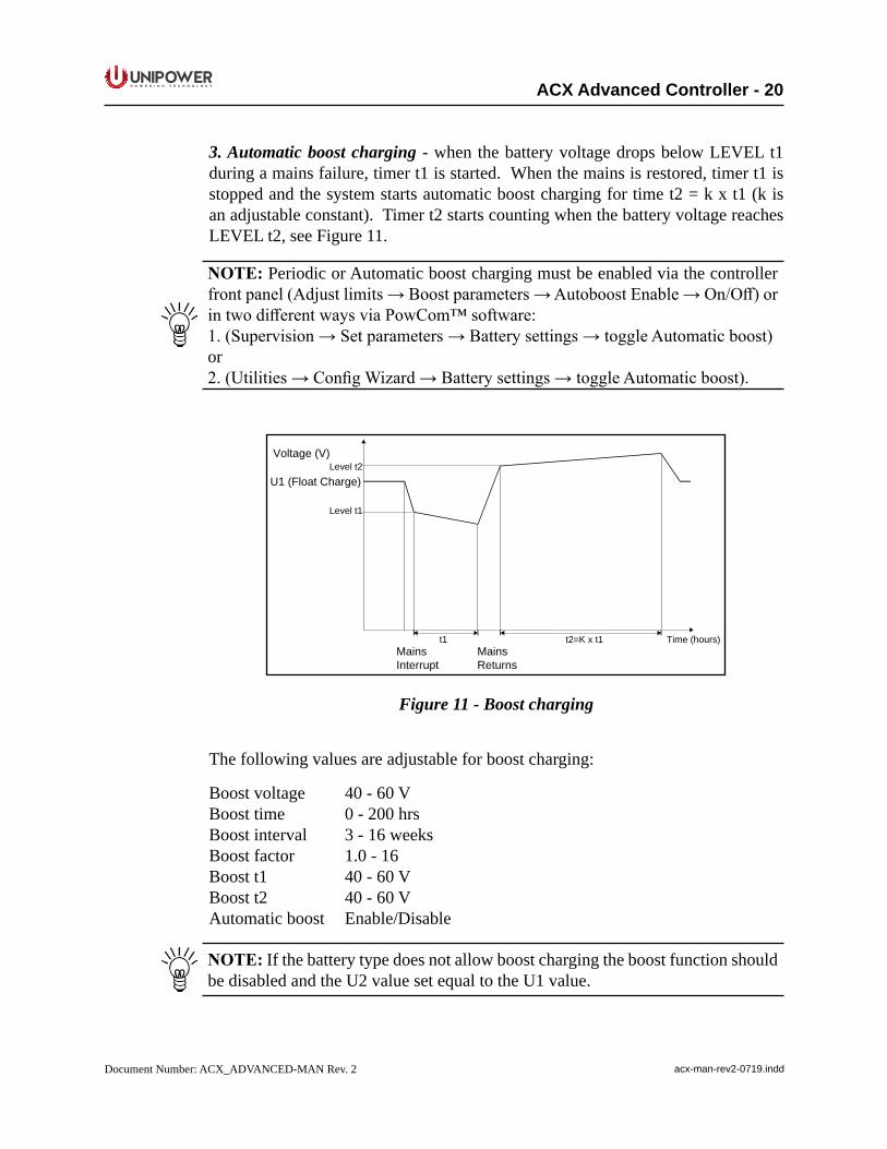
3. Automatic boost charging - when the battery voltage drops below LEVEL t1 during a mains failure, timer t1 is started. When the mains is restored, timer t1 is stopped and the system starts automatic boost charging for time t2 = k x t1 (k is an adjustable constant). Timer t2 starts counting when the battery voltage reaches LEVEL t2, see Figure 11.
NOTE: Periodic or Automatic boost charging must be enabled via the controller frontpanel(Adjustlimits→Boostparameters→AutoboostEnable→On/Off)orintwodifferentwaysviaPowCom™software:1.(Supervision→Setparameters→Batterysettings→toggleAutomaticboost)or2.(Utilities→ConfigWizard→Batterysettings→toggleAutomaticboost).
Voltage (V)Level t2
Level t1
U1 (Float Charge)
MainsInterrupt
MainsReturns
rs)uoh( emiT1txK=2t1t
Figure 11 - Boost charging
The following values are adjustable for boost charging:
Boost voltage 40 - 60 VBoost time 0 - 200 hrsBoost interval 3 - 16 weeksBoost factor 1.0 - 16Boost t1 40 - 60 VBoost t2 40 - 60 VAutomatic boost Enable/Disable
NOTE: If the battery type does not allow boost charging the boost function should be disabled and the U2 value set equal to the U1 value.

P O W E R I N G T E C H N O L O G Y
Document Number: ACX_ADVANCED-MAN Rev. 2 acx-man-rev2-0719.indd
ACX Advanced Controller - 21
4.6.3 BatterySettingsThis menu contains settings for the following battery parameters and limits:
• Symmetry limit (V)• Number of batteries (Branches)• Battery type (Blocks)• Battery capacity (Ah)• Controller Symmetry inputs (-)• Unit 1 - Unit 4 Symmetry inputs (-)
4.6.4 BatteryTestandShortIntervalBatteryTestThis menu contains the following limits and parameters for Battery Test and Short Interval Battery Test:
• Test end voltage (V)• Test end Ah (Ah)• Test duration (Min)• Time of test (-)• Number of tests per year (-)• ShortintervalEnable(On/Off)• Short interval period (Days)• Short interval length (Min)• Short interval deviation (%)
BatteryTestBattery test is used for checking the condition and capacity of installed batteries. The test can be activated Manually or Automatically.
ManualStart-upBattery testing is activated manually by selecting U3 via the controller front panel (Select/ Adjust U1-U4 > Reference > U3) or via PowCom™ software in the Adjust Limits window.
AutomaticStart-upBattery test can be also activated automatically 1-6 times a year via the controller front panel (Adjust Limits > Battery Test > No. of tests per Year) or via PowCom™ software in the Adjust Limits window (Auto Test). The test date is calculated from theinstallationdateofthesystemdefinedinPowCom™software(Supervision>Set installation data).
The day-time (24-hour format) of the battery test is set in ‘Time for Test’.
P O W E R I N G T E C H N O L O G Y
Document Number: ACX_ADVANCED-MAN Rev. 2 acx-man-rev2-0719.indd
ACX Advanced Controller - 22
TestPerformanceOncethebatteryteststarts,therectifiervoltagedecreasestoapre-setvalueU3(checktherectifierdatasheetforminimumvoltage)andisstoppedwhenthesetvalueisreached. Reasons for the test stopping could be:
• battery voltage reaches the End voltage [V]• battery test reaches the Test duration time [min].• discharged capacity reaches the set Ah limit value.
Battery voltage, battery current and Ah are logged during the test. The recommended minimum duration of the test is 5 minutes.
PASSThe battery parameters meet requirements and the voltage reference is set back to U1 when:
• the battery voltage is higher then set End Voltage b. test [V] after expiration of Batt. test time [min].
• the battery voltage is higher then set End Voltage b. test [V] after discharged capacity reaches the set value [Ah].
FAILThe test is interrupted and the battery is considered as faulty when:
• the set voltage value [V] is reached before time [min].• thesetvoltagevalue[V]isreachedbefore“Ahlimitfortest”[Ah].• the symmetry limit is exceeded. SYMMETRY FAULT alarm is activated,
battery test is ended and BATTERY FAILURE alarm is generated.
The battery failure alarm is indicated and further automatically activated battery tests will not be performed while the battery failure alarm is active.
Voltage reference is set to U1 again.
ParameterSettingsThe parameter settings feature allows a partial discharge of the batteries (approximately 30-40% of their capacity) in order to test the batteries for errors. The settings should be done according to the battery manufacturer’s requirements.
The following setting can be used as an example for standard value-regulated lead batteries:
U3 = 1.9V/cellEnd voltage = 1.94V/cellTime = 40% of expected backup timeAh = 40% of nominal battery capacity.
P O W E R I N G T E C H N O L O G Y
Document Number: ACX_ADVANCED-MAN Rev. 2 acx-man-rev2-0719.indd
ACX Advanced Controller - 23
Parameters that can be set or adjusted in the battery test:
BatterytestvoltageU3: 0-100V(CheckRectifierdatasheetformin.voltage.)Symmetry limit: 0.0-4.0VTest end voltage: 0-100VTest duration: 0-20 hoursAh limit: 0-50,000AhTime of test: 0-23 (0=midnight)No of test/year: 0-6
ShortintervalbatterytestThis is used to test for a permanent break or interruption in the battery strings when more than one shunt with extension board is used.
Once this test is Enabled, it is performed in the time interval set in the ‘Short interval period’. The system voltage is decreased to U3 for the time duration set in ‘Short interval length’ and the current through all used shunts is measured. If the current deviationthroughtheshuntsexceedsthevaluesetinthe‘Shortintervaldeviation”orifoneofthecurrentsisequalto0(zero),a‘BatteryFailure”alarmisgenerated.
The test can be Enabled via the controller front panel (Adjust limits > Battery test >ShortIntervalEnable>On/Off)orinoneoftwowaysviaPowCom™software:
1. (Supervision > Set parameters > Battery settings > toggle Short interval Battery Test)
or
2. (Utilities>ConfigWizard>Batterysettingswindow>toggleShort intervalBattery Test).
4.6.5TemperatureCompensationThis menu allows setting of the following parameters for temperature compensation:
• Enabletemperaturecompensation(On/Off)• Compensation factor (V/10°C)• TurntemperaturecompensationOn/Off.
When the battery temperature is higher or lower than 20°C, temperature compensation regulates thesetfloatorboostbatteryvoltagebasedonbattery temperatureandtemperature compensation factor. (This value can be changed to 25°C.)
If the temperature rises by 10 degrees, the voltage decreases according to the adjusted compensation factor, if the temperature drops the voltage is adjusted correspondingly. If the temperature changes by 1 degree, the voltage changes by 1/10 of the compensation factor.
P O W E R I N G T E C H N O L O G Y
Document Number: ACX_ADVANCED-MAN Rev. 2 acx-man-rev2-0719.indd
ACX Advanced Controller - 24
CAUTION: Non-compensating or improper setting shortens battery life by either over- or under-charging.
NOTE: The output voltage is not changed by temp. compensation at a battery temperature 20°C. (This setting can be changed to 25°C)
Example:
A system includes 4 x 12 V battery blocks - 6 cells in each battery block.
The value of 1 cell defined in the battery datasheet:
• 2.28V/20°C• 2.24V/30°C
The difference between values at 20°C and 30°C is 0.04V/cell
6 x 0.04V = 0.24V/10°C - 6 cells in each battery block
The compensation factor value is set for a full battery string which in this case contains 4 x 12V battery blocks. So, the correct compensation factor is:
4 x 0.24V = 0.96V/10°C
NOTE:Theexampleisgeneral.Thetemperaturecompensationfactormaydifferdepending on the installed battery. Check the battery datasheet for correct setting.
4.6.6 BatteryCurrentLimitThis menu allows settings for:
• BatterycurrentlimitEnable(On/Off)• Battery current limit (A)
Thisfunctionlimitsthemaximumcurrentflowingintothebatteriesduringcharging.(It does not limit discharge current!) The minimum charging current is 5A. The maximum charging current value can be set via PowCom™ software to 1000A, via the controller front display it can be higher.
The charging current limit for lead-acid batteries is usually 0.1 of rated capacity. (Checkthebatterydatasheetincaseadifferentvalueisrequired.)
If the current limit is not required or batteries are not installed, keep the function disabled.
CAUTION: Non-limited charge current or improper setting may shorten battery life.
P O W E R I N G T E C H N O L O G Y
Document Number: ACX_ADVANCED-MAN Rev. 2 acx-man-rev2-0719.indd
ACX Advanced Controller - 25
NOTE: Current limiting is not available for all systems that use the ACX Advanced controller. This is the factory default setting.
4.6.7 SystemSpecificLimits(alsoExternalLimits)Theselimitsareusedonlyinspecificsystems.
• External Limit 1 Name of limit• External Limit n Name of limit
There are eight user adjustable limits for PLS logic. If these limits are enabled they canbeadjustedviathecontrollerfrontpanel(Adjustlimits→Systemspecificlimits→Ext.limit1-n)orviaPowCom™software(Supervision→SetParameters→Systemspecificlimits).
4.6.8 ModuleOn/OffModuleOn/Offisusedforswitchingindividualrectifiermodulesonoroff.ThisfunctionneedstobeenabledinConfigWizard.
• ModuleNo.:1(On/Off)• ModuleNo.:n(On/Off)
NOTE:TheconfigurationalsoallowsanEnergySavingModefunctionwheretherectifiersareturnedOnorOffautomaticallybasedonthedeliveredpower.ThisfunctionneedstobeenabledandconfiguredintheConfigWizard.Theautomaticfunction, when active, overrides the manual setting. For more details contact UNIPOWER customer support. (Notavailablewhen4x64Multiplexerinstalled)
4.6.9 No.ofShuntsThe number of battery shunts for the power system is set here. The default number is 1 and this value should not be changed unless extension boards with additional shunts are connected to the system.
4.6.10 FMDsettingsThis sub-menu allows the following settings:
• FMD Voltage (V)• FMD OVP (V)
This menu sets the reference voltage (FMD voltage) and OVP limit for secondary voltage units if these are available in the system.
P O W E R I N G T E C H N O L O G Y
Document Number: ACX_ADVANCED-MAN Rev. 2 acx-man-rev2-0719.indd
ACX Advanced Controller - 26
4.7 MiscellaneousThe miscellaneous menu is used for setting and checking various system parameters.
• Set Time• Relay Test• AlarmBlockingOn/Off• Version• SD Card Info• Set New Password• Shunt Current (A)• Shunt Voltage (mV)• CurrentOffset(A)• VoltageOffset(V)• AudibleAlarmOn/Off• Network Address• Baud Rate• Init Modem• Accept Remove Parts• Reset to Defaults• Master Reset
4.7.1 SetTimeThe time and date are displayed and can be set using the buttons on the controller frontpanel. Theycanalsobe setviaPowCom™software (Supervision→Setdate/time). The clock has a battery back-up and keeps the correct time even if the Controlleristurnedoff.
4.7.2 RelayTestThisfunctionswitchesalarmrelaysOn/Offmanuallyregardlessofanysystemalarms.It is mainly used for testing of alarm relays and related devices.
4.7.3 AlarmBlockingThis function disables all system alarms and alarm relays. The only active and visible alarmis“Alarmsareblocked”.
4.7.4 VersionShowsthecontrollersoftwareversion,configurationnumberandserialnumber.
4.7.5 SDCardInfoProvides the following information about the microSD card status:
• OK - card is working properly• NA - not installed (cannot be detected)• FAIL-filesystemerror(identifieshardware,butcan’tbeusedforreading
or writing)
P O W E R I N G T E C H N O L O G Y
Document Number: ACX_ADVANCED-MAN Rev. 2 acx-man-rev2-0719.indd
ACX Advanced Controller - 27
4.7.6 SetNewPasswordWhenselected,firstentertheoldpassword.Setanewpasswordandconfirmitbyentering the new password again.
NOTE: Make sure the new password is remembered or written down. If the password is forgotten or access is denied, contact UNIPOWER technical support for assistance.
4.7.7 ShuntCurrentDisplays the current rating of the battery shunt, in Amperes [A]. This parameter shows the value of current in the current/voltage ratio of the shunt.
4.7.8 ShuntVoltageDisplays the voltage drop of the battery shunt at rated current, in millivolt [mV]. This parameter shows the value of voltage in the current/voltage ratio of the shunt.
ExampleA shunt with rating 400A/60mV is set as follows: 400A is set as Shunt current and 60mV as Shunt voltage.
4.7.9 CurrentOffsetCurrentoffsetisusedforcalibrationofthecurrentmeasurementinordertoavoidmeasurement offset. To calibrate, turn all battery breakersOFF and adjust theCurrentOffsettozero.
4.7.10 VoltageOffsetThisfunctionsetstheoutputDCvoltagemeasurementsoffset.Measurethevoltageon the DC busbars with a calibrated voltmeter and enter the measured value in the VoltageOffsetmenu.
4.7.11 AudibleAlarmAnaudiblealarmcanbeswitchedOn/Offinthismenuoption.WhenswitchedOnand an alarm occurs the controller makes a sound until any key is pressed.
4.7.12 NetworkAddressFor systems with more than one controller installed in the network setup, this network address must be set to be able to communicate with the PowCom™ software. This setting must not be confused with the controller IP address setting.
The default setting is 2 and it should not be changed for most applications.
4.7.13BaudrateThe speed of communication for RS232 interface can be set here. There are two options 38400 bps or 9600 bps.
P O W E R I N G T E C H N O L O G Y
Document Number: ACX_ADVANCED-MAN Rev. 2 acx-man-rev2-0719.indd
ACX Advanced Controller - 28
4.7.14SNMPVersionThe ACX Advanced supports SNMP in version v1/v2c or v3. The prefered option can be selected here.
4.7.15 InitmodemWhen selected, the controller sends a message to initiate a modem. The initiation messagesetsthemodemtoauto-answeraftertworings.Seetheinstructionsspecificto your modem if it requires additional initialization to operate.
4.7.16 AcceptremovedpartsA unit or module removed from the system generates the Communication failure alarm. Select YES to remove all non-communicating units or modules from the inventory and clear the alarm.
NOTE: Make sure there are no communication faults caused by any other failure beforedoingthis.Itmakesallcommunicationfaultsdisappear;butitwillnotfixany problems, so it must only be used if the communication fault is caused by the module or unit being intentionally removed.
4.7.17 ResettodefaultsThis command returns all settings of the system to default values without deleting logged data or system information. It is recommended to try this instead of Master Reset if a reset is needed. After reset always check all limits and adjust them to the required levels.
4.7.18 MasterresetA master reset completely resets the controller and deletes all stored data including the password. If possible, perform a backup of the controller data to a PC before doing a master reset. After a master reset always check all limits and adjust them to the desired levels.
CAUTION: A Master Reset deletes all information from the system.Use the master reset feature only as a last resort.
4.8 EnergySavingModeInthismodetheACXAdvancedcontrollerisabletoturnoffredundantrectifiersautomaticallydependingontheload.Atleast2rectifiersremainactiveandrotatein a set time periods on every address position.
NOTE: This function can only be enabled/disabled using the PowCom software. See page 28 in the PowCom manual for more details.
P O W E R I N G T E C H N O L O G Y
Document Number: ACX_ADVANCED-MAN Rev. 2 acx-man-rev2-0719.indd
ACX Advanced Controller - 29
Show
alar
msFM
D V
olt:
xx.x
x V
FMD
Cur
r:xx
.xx
ABa
ttcur
r:xx
.xx
AD
istcu
rr:xx
.xx
AR
ectc
urr:
xx.x
x A S
how
mes
sage
s
Show
dat
a
Sel
ect/a
djus
tU
1 –
U4
Alar
ms:
Low
vol
t ala
rm
Alar
ms:
Hig
h vo
lt al
arm
U1
Floa
t vol
tage
:xx
.xx
V
U2
Boo
st v
olta
ge:
xx.x
x V
U3
Test
volta
ge:
xx.x
x V
U4
Spa
re v
olta
ge:
xx.x
x V
Ref
eren
ce:
U1
Sho
wm
odul
eda
ta
Show
uni
tdat
a
Show
SLI
data
Tem
pera
ture
Ext:
xx.x
x °C
Int:
xx.x
x°C
Rem
aini
ngba
ttery
time:
xM
ins
Ext
erna
lm
easu
rem
ents
Sym
met
rym
easu
rem
ents
Strin
g:1
1:xx
.xx
2: x
x.xx
3:xx
.xx
4: x
x.xx
Strin
g:n
1:xx
.xx
2: x
x.xx
3:xx
.xx
4: x
x.xx
Exte
rnal
mea
s: 1
Nam
ex
Exte
rnal
mea
s: n
Nam
ex
U.n
o:1
Com
:Ok/
Fail
I=xx
.xx
A
U.n
o:n
Com
:Ok/
Fail
I=xx
.xx
A
U.n
o: 1
xx.x
x°C
Sno
:xx
xxxx
xxV
er.:
xx.x
x
U.n
o: n
xx.x
x°C
Sno
:xx
xxxx
xxV
er.:
xx.x
x
M.n
o:1
Com
:Ok/
Fail
I= x
x.xx
AU
=xx
.xx
VIm
=xx
.xx
A
M.n
o:n
Com
:Ok/
Fail
I= x
x.xx
AU
=xx
.xx
VIm
=xx
.xx
A
M.n
o: 1
xx.x
x °C
OVP
=xx
.xx
VC
urr l
imit=
x %
M.n
o: n
xx.x
x °C
OVP
=xx
.xx
VC
urr l
imit=
x %
M.n
o: 1
Alar
ms
MN
S/ L
OW
/ O
FF/ O
VS /
FAN
/ CU
R/ T
MP
/PH
S /
CO
M
M.n
o: n
Alar
ms
MN
S/ L
OW
/ O
FF/ O
VS /
FAN
/ CU
R/ T
MP
/PH
S /
CO
M
M.n
o: 1
AC=
xS
no:
xxxx
xxxx
Ver
.:xx
.xx
M.n
o: n
AC=
xS
no:
xxxx
xxxx
Ver
.:xx
.xx
1.1
1
2 3 4 5
2.1
5.1
4.1
4.1.
2.1
4.1.
1.1.
1.1
4.1.
1.1.
1.1.
1
4.1.
7.1
5.2
5.3
5.4
5.5
4.1.
2
4.1.
3
4.1.
4
4.1.
5
4.1.
6
4.1.
7
4.1.
7.1
4.1.
6.1
4.1.
6.1
4.1.
2.1
4.1.
2.1.
1
4.1.
2.1.
1
4.1.
1.1
4.1.
1.1
4.1.
1.1.
1
4.1.
1.1.
14.
1.1.
1.1.
14.
1.1.
1.1.
1.1
2.1
Alar
ms:
LVD
alar
m
2.1
Alar
ms:
Mai
nsfa
ilure
2.1
Alar
ms:
Load
bre
aker
al
2.1
Alar
ms:
Low
AC
volta
ge
2.1
Alar
ms:
Batt.
test
fail
2.1
Alar
ms:
Mod
ule
alar
m
2.1
Alar
ms:
Hig
hba
tt.te
mp
2.1
Alar
ms:
Batt.
sym
alar
m
2.1
Alar
ms:
Batt.
fuse
alar
m
2.1
Alar
ms:
Hig
h lo
ad
2.1
Alar
ms:
Hig
h AC
volta
ge
2.1
Ala
rms:
Urg
ent m
odul
e al
2.1
Ala
rms:
Com
.ala
rm
2.1
Ala
rms:
PLD
alar
m
2.1
Ala
rms:
Tem
p.pr
obe
fail
2.1
Ala
rms:
Dist
rloa
d hi
gh
2.1
Ala
rms:
Bat
t on
disc
hrg
2.1
Ala
rms:
OVS
alar
m
2.1
Ala
rms:
Low
bat
t.tem
p
2.1
Ala
rms:
PLD
2 al
arm
2.1
Ala
rms:
PLD
3 al
arm
2.1
Ala
rms:
Ala
rms
bloc
ked
Ala
rms:
U2
Boos
t
Ala
rms:
U3
Test
Ala
rms:
U4
Spar
e
2.1
2.1
2.1
2.1
Mes
sage
s:Lo
w v
olt a
larm
Mes
sage
s:H
igh
volt
alar
m
3.1
3.1
Mes
sage
s:LV
Dal
arm
3.1
Mes
sage
s:M
ains
failu
re
3.1
Mes
sage
s:Lo
adbr
eake
ral
3.1
Mes
sage
s:Lo
wA
C v
olta
ge
3.1
Mes
sage
s:Ba
tt.te
st fa
il
3.1
Mes
sage
s:M
odul
eal
arm
3.1
Mes
sage
s:H
igh
batt.
tem
p
3.1
Mes
sage
s:Ba
tt.sy
m a
larm
3.1
Mes
sage
s:Ba
tt.fu
se a
larm
3.1
Mes
sage
s:H
igh
load
3.1
Mes
sage
s:H
igh
AC
volta
ge
3.1
Mes
sage
s:U
rgen
t mod
ule
al
3.1
Mes
sage
s:C
om.a
larm
3.1
Mes
sage
s:P
LD a
larm
3.1
Mes
sage
s:Te
mp.
prob
e fa
il
3.1
Mes
sage
s:D
istrl
oad
high
3.1
Mes
sage
s:B
att o
n di
schr
g
3.1
Mes
sage
s:O
VSal
arm
3.1
Mes
sage
s:Lo
w b
att.t
emp
3.1
Mes
sage
s:P
LD 2
ala
rm
3.1
Mes
sage
s:P
LD 3
ala
rm
3.1
Mes
sage
s:A
larm
s bl
ocke
d
Mes
sage
s:U
2B
oost
Mes
sage
s:U
3Te
st
Mes
sage
s:U
4S
pare
3.1
3.1
3.1
3.1
Mod
ule
Cha
nnel
x
4.1.
1
Conti
nue o
n nex
t pag
e
Ente
r
Can
cel
Up/
Dow
n
Line
col
ors:
Figure 12a - Menu Tree part 1
P O W E R I N G T E C H N O L O G Y
Document Number: ACX_ADVANCED-MAN Rev. 2 acx-man-rev2-0719.indd
ACX Advanced Controller - 30
Adj
ust l
imits
Misc
ella
nous
Set T
ime:
XX:X
X:X
XX
X/XX
/XX
XX
Rep
lyte
st
Ala
rmbl
ockin
g
On/
Off
Vers
ion
SD
Car
d In
fo
Set
new
pass
wor
d
Shu
ntcu
rrent
xx.x
x A
Shu
nt v
olta
gexx
.xx
mV
Cur
rent
offs
etEn
sure
fuse
s of
fxx
.xx
A
Vol
tage
offs
et
xx.x
x V
Avai
labl
e al
arm
On/
Off
Net
wor
k ad
ress
Bau
dra
te
xxxx
Init
mod
em
Acce
pt re
mov
edPa
rts
Res
etto
defa
ults
Mas
terr
eset
AC
C:
V.xx
.xx
Sno:
xxxx
xxxx
xC
fg:
xxxx
xxx
Stat
e:N
A
Pow
Com
adr:
X
TCP/
IPad
r:xx
x.xx
x.xx
x.xx
x
Net
mas
k:xx
x.xx
x.xx
x.xx
x
Def
ault
gate
way
:xx
x.xx
x.xx
x.xx
x
Ala
rm li
mits
Boos
tpar
amte
rs
Bat
tery
setti
ngs
Bat
tery
test
Tem
pera
ture
com
pens
atio
n
Bat
tery
curre
ntlim
it
Syst
em s
pecif
iclim
its
Mod
ule
on/o
ff
Num
ber o
f shu
nts
X
FMD
Set
tings
FMD
Vol
t:
xx.x
x V
FMD
OV
P:
xx.x
x V
Ext
Lim
it1
Nam
eof
limit xx
.xx
Ext
Lim
itn
Nam
eof
limit xx
.xx
M.n
o: 1
On/
Off
M.n
o: n
On/
Off
Bat
t.cu
r. lim
itE
nabl
e:O
n/O
ff
Batte
ry c
urre
ntLi
mit
xx.x
x A
Enab
le te
mp.
com
pens
astio
n:O
n/O
ff
Com
p. fa
ctor
:
xx.x
x V
/ xx.
xx°C
Test
end
volta
gexx
.xx
V
Test
end
Ahxx
.xx
Ah
Test
dura
tion
x M
ins
Tim
e of
test
:
x
No
of te
sts
per
year
:x
Sho
rtin
terv
alEn
able
:O
n/O
ff
Sho
rtin
terv
alpe
riod:
x da
ys
Sho
rtin
terv
alle
ngth
:x
Min
s
Sho
rtin
terv
alde
viat
ion:
x %
Sym
met
ry li
mit
xx.x
x V
No
of b
atte
ruie
s:
xB
ranc
hes
Batte
ry ty
pe:
xB
lock
s
Batte
ry c
apac
ity
xx.x
x Ah
ACC
Sym
met
ry in
puts
x
Uni
t 1S
ymm
etry
inpu
tsx
Uni
t 2S
ymm
etry
inpu
tsx
Uni
t 3S
ymm
etry
inpu
tsx
Uni
t 4S
ymm
etry
inpu
tsx
Boos
t tim
e:
x H
ours
Boos
tint
erva
l:
xW
eeks
Boos
tfac
tor:
x
Boo
st t1
:
xx.x
x V
Boo
st t2
:
xx.x
x V
Aut
oboo
stEn
able
:O
n/O
ff
Low
vol
tage
:
xx.x
x V
Hig
h vo
ltage
:
xx.x
x V
Ove
rvol
tage
Shu
tdow
n:xx
.xx
V
Load
/bat
tery
disc
onne
ct:
xx.x
x V
Parti
allo
addi
scon
nect
:xx
.xx
V
Parti
allo
ad 2
disc
onne
ct:
xx.x
x V
Parti
allo
ad 3
disc
onne
ct:
xx.x
x V
Load
/bat
tery
reco
nnec
t:xx
.xx
V
Hig
hlo
ad:
x %
Tem
pera
ture
Ala
rm:
Hig
ht: x
x.xx
°C
Tem
pera
ture
Ala
rm:
Low
: xx.
xx °C
Low
AC
volta
ge:
xx.x
x V
Hig
h AC
vol
tage
:
xx.x
x V
Ente
r
Can
cel
Up/
Dow
n
Line
col
ors:
6 7
6.1
6.6.
1
6.6.
2
6.5.
1
6.5.
2
6.4.
1
6.4.
2
6.4.
3
6.4.
4
6.4.
5
6.4.
6
6.4.
7
6.4.
8
6.4.
9
6.3.
1
6.3.
2
6.3.
3
6.3.
4
6.3.
5
6.3.
6
6.3.
7
6.3.
8
6.3.
9
6.2.
1
6.2.
2
6.2.
3
6.2.
4
6.2.
5
6.2.
6
6.1.
1
6.1.
2
6.1.
3
6.1.
4
6.1.
5
6.1.
6
6.1.
7
6.1.
8
6.1.
9
6.1.
10
6.1.
11
6.1.
12
6.1.
13
7.1
7.2
7.3
7.4
7.5
7.6
7.7
7.8
7.9
7.10
7.11
7.12
7.13
7.15
7.16
7.17
7.12
.1
7.12
.2
7.12
.3
7.12
.4
7.5.
1
7.4.
1
6.2
6.3
6.4
6.5
6.6
6.7
6.8
6.10
6.11
6.11
.1
6.11
.2
6.8.
1.1
6.8.
1.1
6.7.
1
6.7.
1
Ener
gy s
ave
mod
e6.9
Ener
gy s
ave
mod
eE
nabl
e:O
n
Rot
atio
n tim
e :
xx.x
xH
ours6.
9.1
6.9.
2
SNM
Pve
rsio
nxx
x
7.14
7.18
Mod
ule
Cha
nnel
x
6.8.
1
From
prev
ious p
age
Figure 12b - Menu Tree part 2
P O W E R I N G T E C H N O L O G Y
Document Number: ACX_ADVANCED-MAN Rev. 2 acx-man-rev2-0719.indd
ACX Advanced Controller - 31
5. Controller Alarms / MessagesThischapterdescribesthecontrolleralarmsinstandardsystemoperationandconfiguration:
LowsystemvoltageThis alarm is generated when the system voltage drops below the limit set in 4.6.1 - Low voltage alarm.
HighsystemvoltageThis alarm occurs when the system voltage exceeds the limit set in 4.6.1 - High voltage alarm.
Load/BatterydisconnectionThis alarm is generated when the system voltage drops below the limit set in 4.6.1 - Load/Battery disconnection for more than 30s. Load/Battery disconnection must be allowed in theconfiguration.
MainsErrorThisalarmisactivatedwhenACmainsisOfffortwoormorerectifiersexceptforsystemswithonerectifieronly.
DistributionfusefailureThisalarmoccurswhenadistributioncircuitbreakerisswitchedOff.Aloadneedstobeconnected to the breaker as the alarm does not occur if there no load connected.
AClowvoltageThis alarm is generated when the AC Mains voltage drops below the limit set in 4.6.1 - Low AC voltage.
ThisalarmisavailableonlywhenrectifierswithanACmainsvoltagereadingareusedinthe system.
BatteryfailureThis alarm occurs when either a Battery test or a Short interval Battery Test Fails. This alarm needs to be reset manually. For details see 4.6.4.
ModulefailureThis alarm occurs when one of the installed modules indicates a failure alarm.
HighbatterytemperatureThis alarm occurs when the battery temperature exceeds the limit set in 4.6.1 - High temperature alarm.
SymmetryfaultThisalarmisgeneratedwhenthevoltagebetweenbatteryblocksdiffersfromthevaluesetin 4.6.3 - Battery Settings.
This value is calculated from the system voltage based on the battery settings, number of batteries and battery type.
P O W E R I N G T E C H N O L O G Y
Document Number: ACX_ADVANCED-MAN Rev. 2 acx-man-rev2-0719.indd
ACX Advanced Controller - 32
IfAutomaticResetisnotenabledintheconfiguration,thealarmneedstoberesetmanually.
BatteryfusefailureThisalarmoccurswhenabatterycircuitbreakerisswitchedOffandthesystemvoltageis 0.65V higher than the battery voltage. The alarm does not occur when a battery is not connected.(Infirmwareolderthan1.13isthevalue1.4V.)
HighloadThisalarmisactivatedwhentheloadcurrentexceedsthecapacityoftheinstalledrectifiersmultiplied by the limit set in 4.6.1 - High load.
ACHighVoltageThis alarm occurs when the AC Mains voltage exceeds the limit set in 4.6.1 - High AC voltage.
ThisalarmisactivatedonlywhenrectifierswithACmainsvoltagereadingareusedinthesystem.
UrgentmodulefailureThis alarm occurs when two or more installed modules send a failure alarm.
CommunicationfailureThis alarm occurs when installed modules or units are not communicating or are removed from the system. For detail see section 3.2.
PLDDisconnectionThis alarm occurs either when the system voltage drops below the set limit, or when the time reaches the value set in 4.6.1 - Partial load disconnect.
Voltagedisconnectionneedstobeallowedintheconfiguration.
Temp.probefailureThis alarm always appears when:
• The temperature probe is disconnected and temperature compensation is enabled.• Battery temperature is above +80°C or below -20°C, temperature compensation can
be enabled or disabled. (If disabled and temperature is below -40°C the alarm does not appear.)
• Battery temperature is 10°C higher than the temperature of the controller’s internal temperature sensor.
• Battery temperature is 30°C lower than the temperature of the controller’s internal temperature sensor.
This alarm does not appear when:
• The temperature probe is disconnected and temperature compensation is disabled.• Temperature compensation is disabled and the temperature drops below -40°C.
P O W E R I N G T E C H N O L O G Y
Document Number: ACX_ADVANCED-MAN Rev. 2 acx-man-rev2-0719.indd
ACX Advanced Controller - 33
HighdistributionloadIs not used in controller managed systems.
BatteryisdischargingThis alarm appears when the battery is discharging with current higher than 2% of the current rating of the shunt and the system voltage drops 1V below the voltage reference (U1 or U2).
OvervoltageshutdownThisalarmappearswhenthesystemvoltageexceedstherectifierovervoltageshutdownlimitandtherectifiersareswitchedOff.Therectifiersusuallyneedtoberestartedaftersuch an event.
LowbatterytemperatureThis alarm is activated when the battery temperature drops below the temperature set in 4.6.1 - Low temperature alarm
PLD2DisconnectionThis alarm occurs either when the system voltage drops below the set limit, or when the time reaches the value set in 4.6.1 - Partial load 2 disconnect.
Voltagedisconnectionneedstobeallowedintheconfiguration.
PLD3DisconnectionThis alarm occurs either when the system voltage drops below the set limit, or when the time reaches the value set in 4.6.1 - Partial load 3 disconnect.
Voltagedisconnectionneedstobeallowedintheconfiguration.
AlarmsareblockedThis alarm occurs when the Alarms are blocked function is used, see 4.7.3.
16xAdditionalUserDefinableAlarmsThesealarmsaretriggeredwhenuserdefinedalarmsmeetthealarmcondition.Thealarmtextisdefinedbytheuser.
P O W E R I N G T E C H N O L O G Y
Document Number: ACX_ADVANCED-MAN Rev. 2 acx-man-rev2-0719.indd
ACX Advanced Controller - 34
6. Connection to Controller via PowCom™ software
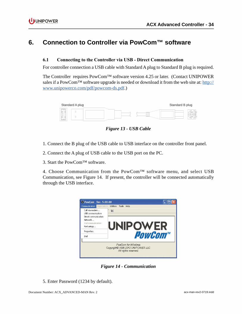
6.1 ConnectingtotheControllerviaUSB-DirectCommunicationFor controller connection a USB cable with Standard A plug to Standard B plug is required.
The Controller requires PowCom™ software version 4.25 or later. (Contact UNIPOWER sales if a PowCom™ software upgrade is needed or download it from the web site at: http://www.unipowerco.com/pdf/powcom-ds.pdf.)
gulpBdradnatSgulpAdradnatS
Figure 13 - USB Cable
1. Connect the B plug of the USB cable to USB interface on the controller front panel.
2. Connect the A plug of USB cable to the USB port on the PC.
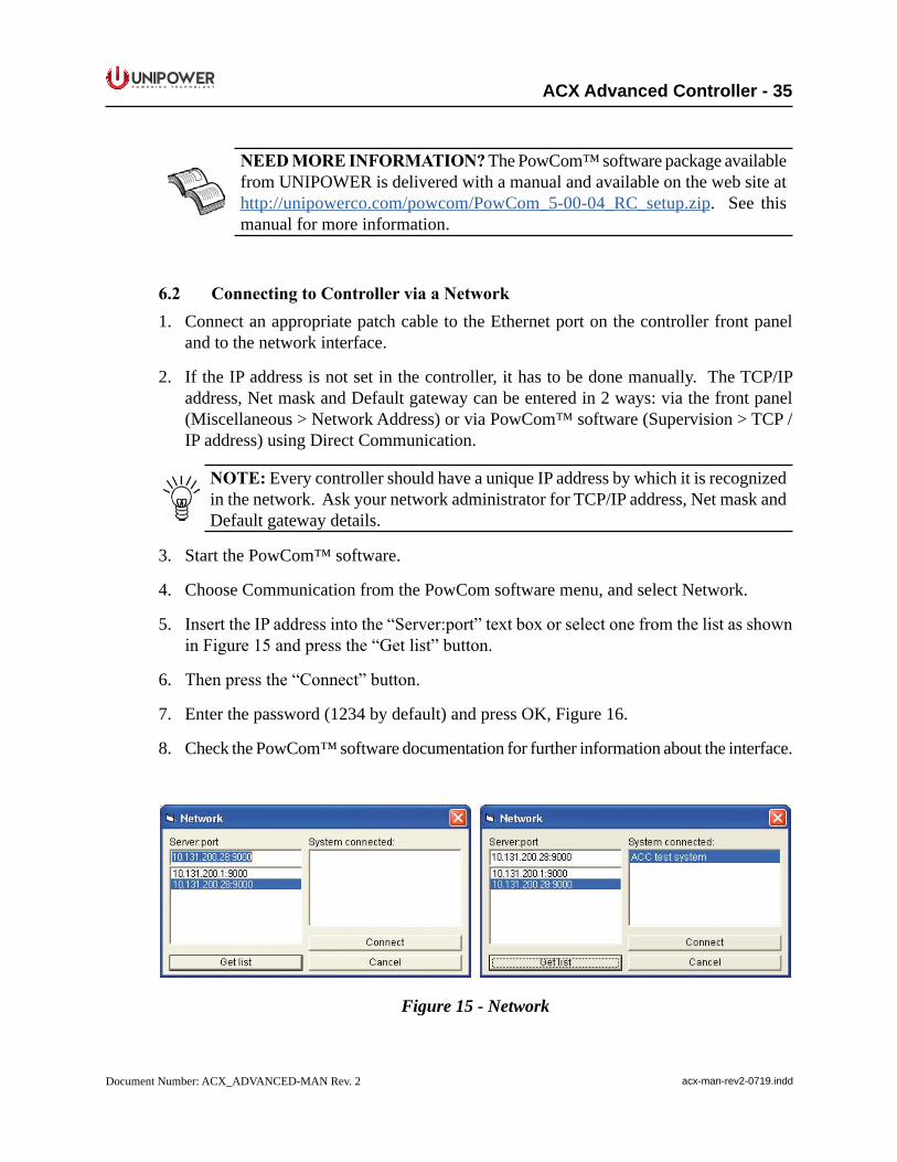
3. Start the PowCom™ software.
4. Choose Communication from the PowCom™ software menu, and select USB Communication, see Figure 14. If present, the controller will be connected automatically through the USB interface.
Figure 14 - Communication
5. Enter Password (1234 by default).
P O W E R I N G T E C H N O L O G Y
Document Number: ACX_ADVANCED-MAN Rev. 2 acx-man-rev2-0719.indd
ACX Advanced Controller - 35
NEEDMOREINFORMATION? The PowCom™ software package available from UNIPOWER is delivered with a manual and available on the web site at http://unipowerco.com/powcom/PowCom_5-00-04_RC_setup.zip. See this manual for more information.
6.2 ConnectingtoControllerviaaNetwork1. Connect an appropriate patch cable to the Ethernet port on the controller front panel
and to the network interface.
2. If the IP address is not set in the controller, it has to be done manually. The TCP/IP address, Net mask and Default gateway can be entered in 2 ways: via the front panel (Miscellaneous > Network Address) or via PowCom™ software (Supervision > TCP / IP address) using Direct Communication.
NOTE: Every controller should have a unique IP address by which it is recognized in the network. Ask your network administrator for TCP/IP address, Net mask and Default gateway details.
3. Start the PowCom™ software.
4. Choose Communication from the PowCom software menu, and select Network.
5. InserttheIPaddressintothe“Server:port”textboxorselectonefromthelistasshowninFigure15andpressthe“Getlist”button.
6. Thenpressthe“Connect”button.
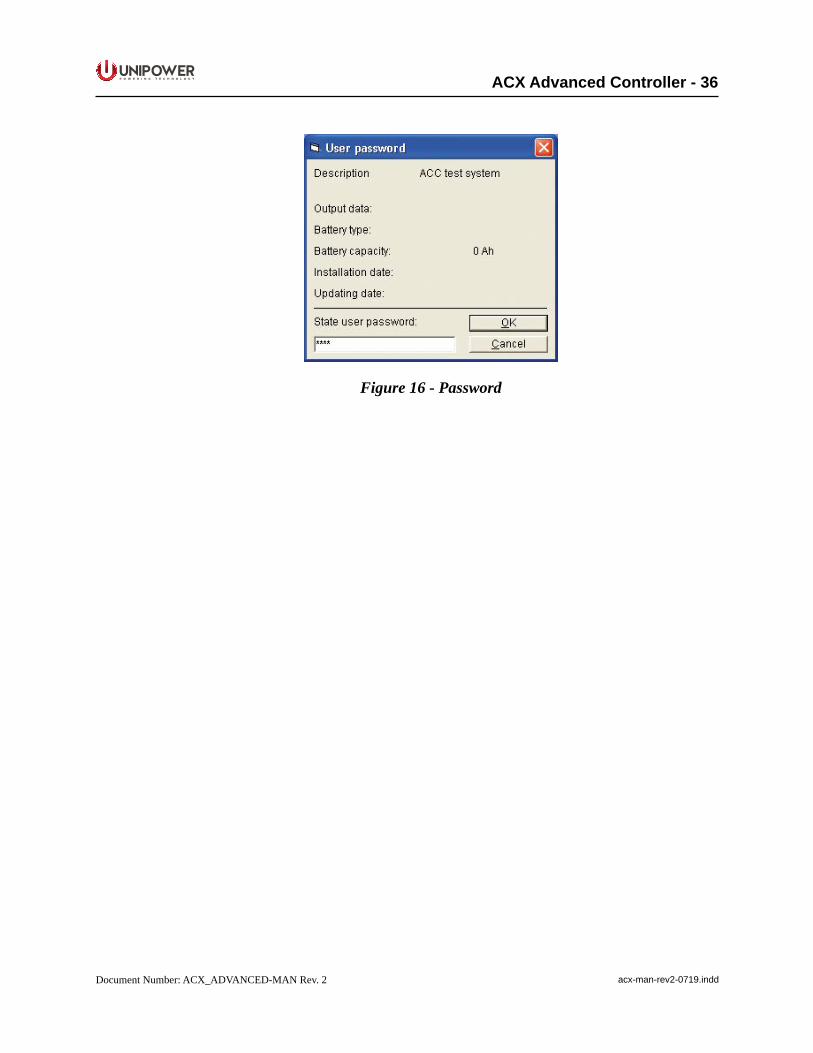
7. Enter the password (1234 by default) and press OK, Figure 16.
8. Check the PowCom™ software documentation for further information about the interface.
Figure 15 - Network
P O W E R I N G T E C H N O L O G Y
Document Number: ACX_ADVANCED-MAN Rev. 2 acx-man-rev2-0719.indd
ACX Advanced Controller - 36
Figure 16 - Password
P O W E R I N G T E C H N O L O G Y
Document Number: ACX_ADVANCED-MAN Rev. 2 acx-man-rev2-0719.indd
ACX Advanced Controller - 37
7. Connecting to the Controller via the Web InterfaceThe controller can be also monitored via an Ethernet 100 BASE-T network using the built-in Web Interface software application.
The Web Interface allows monitoring and setting of the main system parameters and alarms. The browser is automatically refreshed approximately every half-minute.
The Web Interface requires an up to date graphical Internet browser (MS Internet Explorer, Mozilla Firefox or other).
UNIPOWER does not guarantee compatibility with older browser software versions.
NOTE: For connectivity verification in the network between the PC and thecontroller, it is possible to use ICMP (Internet Control Message Protocol). It is chieflyusedby the operating systemsof networked computers to send errormessages—indicating, for instance, that a requested service is not available or that a host or router could not be reached.The ping tool is used directly by user network applications. It sends an “Echo request”andexpectsan“Echoreplay”.Thecontrollercanworkwithmax.1024Bytes only (Windows ping default).
7.1 ConnectionFor Ethernet connection via the Web Interface, follow the instructions below:
1. Connect an appropriate patch cable to the Ethernet Connection on the controller front panel and to the network interface.
2. If the IP address is not set in the controller it has to be done manually. The TCP/IP address, Net mask and Default gateway can be entered in 2 ways: via the front panel (Miscellaneous > Network Address) or via PowCom™ software (Direct communication > Supervision > TCP / IP address).
NOTE: Every controller should have a unique IP address by which is recognized in the network. Ask your network administrator for TCP/IP address, Net mask and Default gateway details.
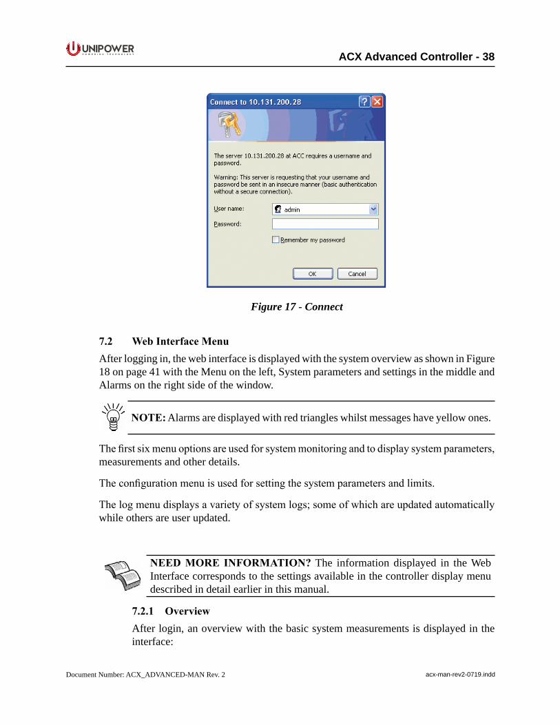
3. Start the Internet browser on the computer and enter the IP address in the Address bar after HTTP and you should get a connection box, see Figure 17 on page 40.
4. Whenlogginginforthefirsttime,enter‘admin’asUsernameandleavethePasswordfieldblank. If a User Account already exists, enter the appropriate Username and Password.
NOTE:thePasswordcanbeeditedafterloginusingtheConfiguration-Adminmenuontheleftside. SeeAdminConfiguration7.2.8.1forfurtherinformationregarding login, user levels and password editing.
P O W E R I N G T E C H N O L O G Y
Document Number: ACX_ADVANCED-MAN Rev. 2 acx-man-rev2-0719.indd
ACX Advanced Controller - 38
Figure 17 - Connect
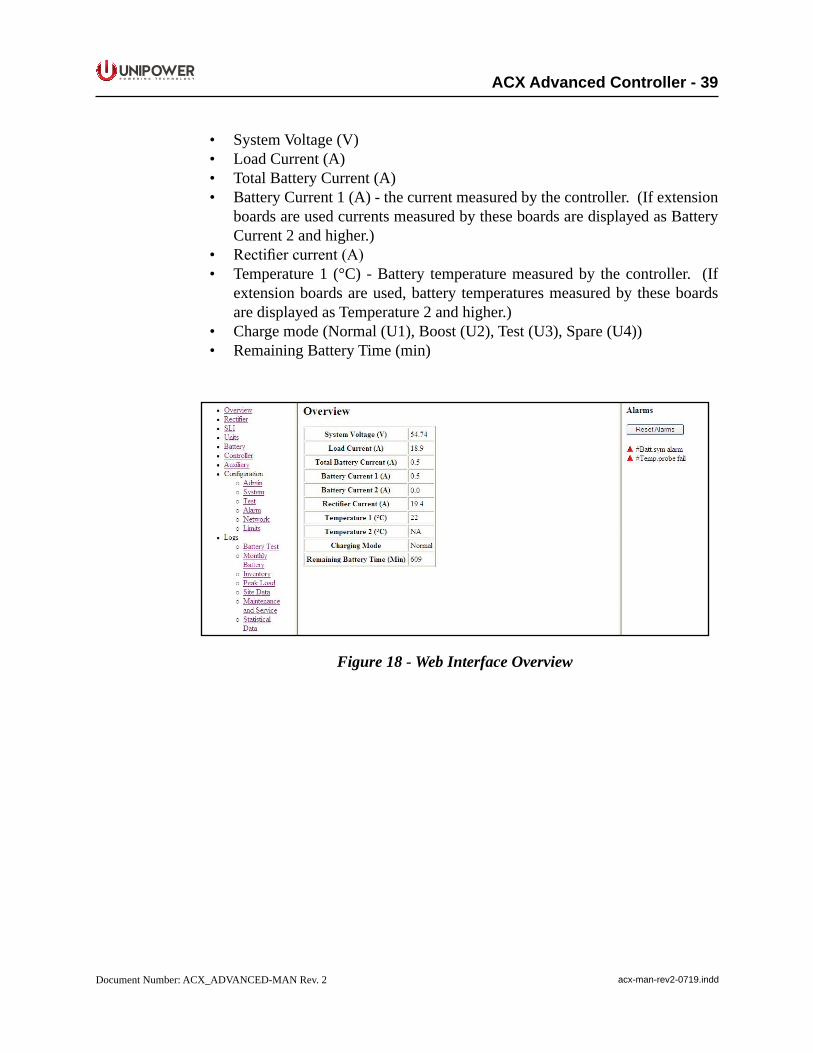
7.2 WebInterfaceMenuAfter logging in, the web interface is displayed with the system overview as shown in Figure 18 on page 41 with the Menu on the left, System parameters and settings in the middle and Alarms on the right side of the window.
NOTE: Alarms are displayed with red triangles whilst messages have yellow ones.
Thefirstsixmenuoptionsareusedforsystemmonitoringandtodisplaysystemparameters,measurements and other details.
Theconfigurationmenuisusedforsettingthesystemparametersandlimits.
Thelogmenudisplaysavarietyofsystemlogs;someofwhichareupdatedautomaticallywhile others are user updated.
NEEDMORE INFORMATION? The information displayed in the Web Interface corresponds to the settings available in the controller display menu described in detail earlier in this manual.
7.2.1 OverviewAfter login, an overview with the basic system measurements is displayed in the interface:
P O W E R I N G T E C H N O L O G Y
Document Number: ACX_ADVANCED-MAN Rev. 2 acx-man-rev2-0719.indd
ACX Advanced Controller - 39
• System Voltage (V)• Load Current (A)• Total Battery Current (A)• Battery Current 1 (A) - the current measured by the controller. (If extension
boards are used currents measured by these boards are displayed as Battery Current 2 and higher.)
• Rectifiercurrent(A)• Temperature 1 (°C) - Battery temperature measured by the controller. (If
extension boards are used, battery temperatures measured by these boards are displayed as Temperature 2 and higher.)
• Charge mode (Normal (U1), Boost (U2), Test (U3), Spare (U4))• Remaining Battery Time (min)
Figure 18 - Web Interface Overview
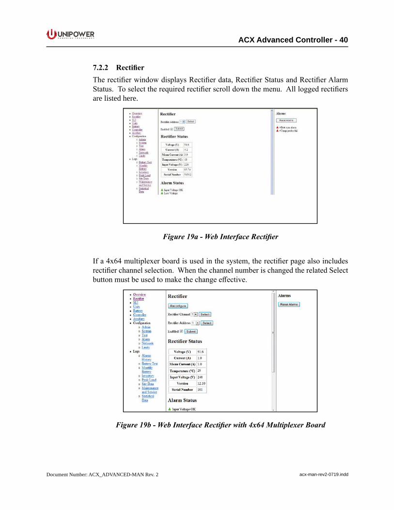
P O W E R I N G T E C H N O L O G Y
Document Number: ACX_ADVANCED-MAN Rev. 2 acx-man-rev2-0719.indd
ACX Advanced Controller - 40
7.2.2 RectifierTherectifierwindowdisplaysRectifierdata,RectifierStatusandRectifierAlarmStatus.Toselecttherequiredrectifierscrolldownthemenu.Allloggedrectifiersare listed here.
Figure 19a - Web Interface Rectifier
Ifa4x64multiplexerboardisusedinthesystem,therectifierpagealsoincludesrectifierchannelselection.WhenthechannelnumberischangedtherelatedSelectbuttonmustbeusedtomakethechangeeffective.
Figure 19b - Web Interface Rectifier with 4x64 Multiplexer Board
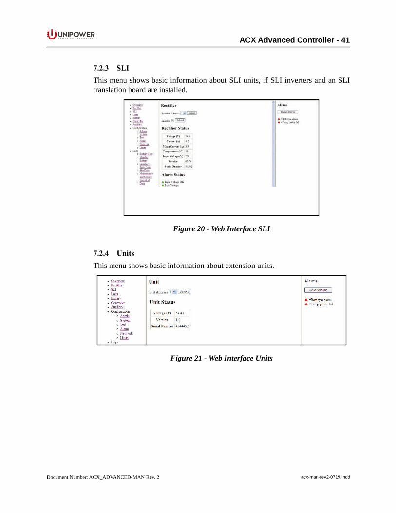
P O W E R I N G T E C H N O L O G Y
Document Number: ACX_ADVANCED-MAN Rev. 2 acx-man-rev2-0719.indd
ACX Advanced Controller - 41
7.2.3 SLIThis menu shows basic information about SLI units, if SLI inverters and an SLI translation board are installed.
Figure 20 - Web Interface SLI
7.2.4 UnitsThis menu shows basic information about extension units.
Figure 21 - Web Interface Units
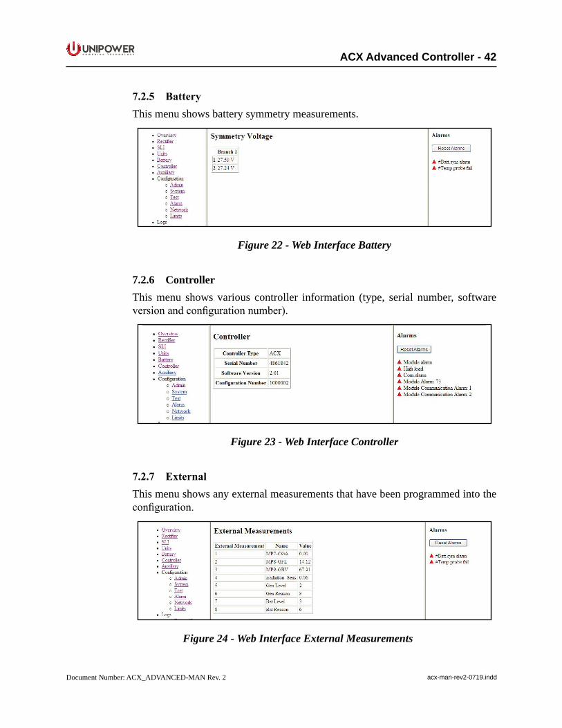
P O W E R I N G T E C H N O L O G Y
Document Number: ACX_ADVANCED-MAN Rev. 2 acx-man-rev2-0719.indd
ACX Advanced Controller - 42
7.2.5 BatteryThis menu shows battery symmetry measurements.
Figure 22 - Web Interface Battery
7.2.6 ControllerThis menu shows various controller information (type, serial number, software versionandconfigurationnumber).
Figure 23 - Web Interface Controller
7.2.7 ExternalThis menu shows any external measurements that have been programmed into the configuration.
Figure 24 - Web Interface External Measurements
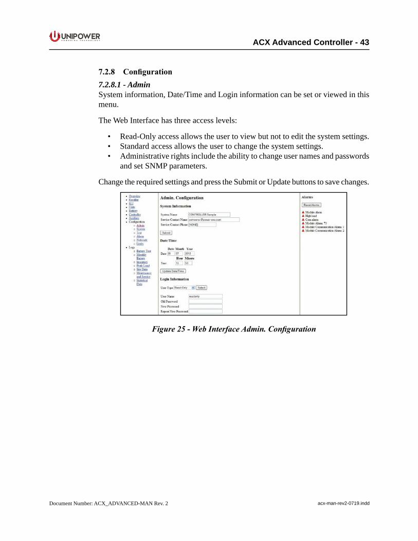
P O W E R I N G T E C H N O L O G Y
Document Number: ACX_ADVANCED-MAN Rev. 2 acx-man-rev2-0719.indd
ACX Advanced Controller - 43
7.2.8 Configuration7.2.8.1 - AdminSystem information, Date/Time and Login information can be set or viewed in this menu.
The Web Interface has three access levels:
• Read-Only access allows the user to view but not to edit the system settings.• Standard access allows the user to change the system settings.• Administrative rights include the ability to change user names and passwords
and set SNMP parameters.
Change the required settings and press the Submit or Update buttons to save changes.
Figure 25 - Web Interface Admin. Configuration
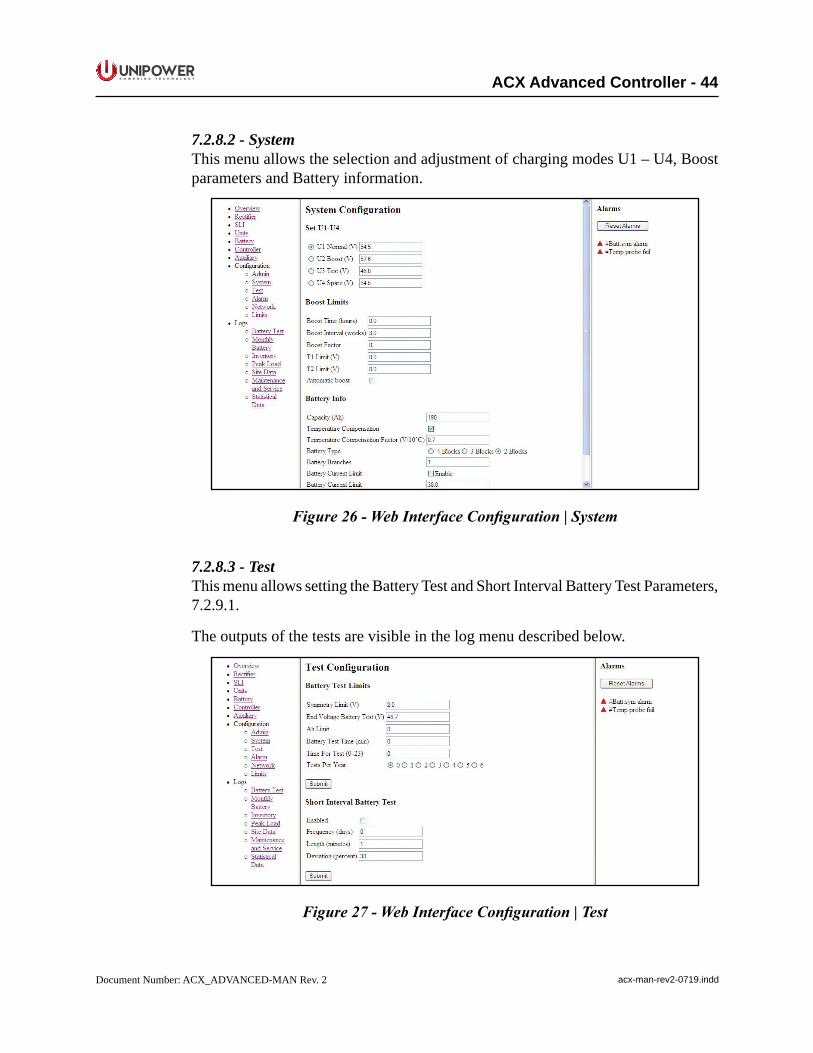
P O W E R I N G T E C H N O L O G Y
Document Number: ACX_ADVANCED-MAN Rev. 2 acx-man-rev2-0719.indd
ACX Advanced Controller - 44
7.2.8.2 - SystemThis menu allows the selection and adjustment of charging modes U1 – U4, Boost parameters and Battery information.
Figure 26 - Web Interface Configuration | System
7.2.8.3 - TestThis menu allows setting the Battery Test and Short Interval Battery Test Parameters, 7.2.9.1.
The outputs of the tests are visible in the log menu described below.
Figure 27 - Web Interface Configuration | Test
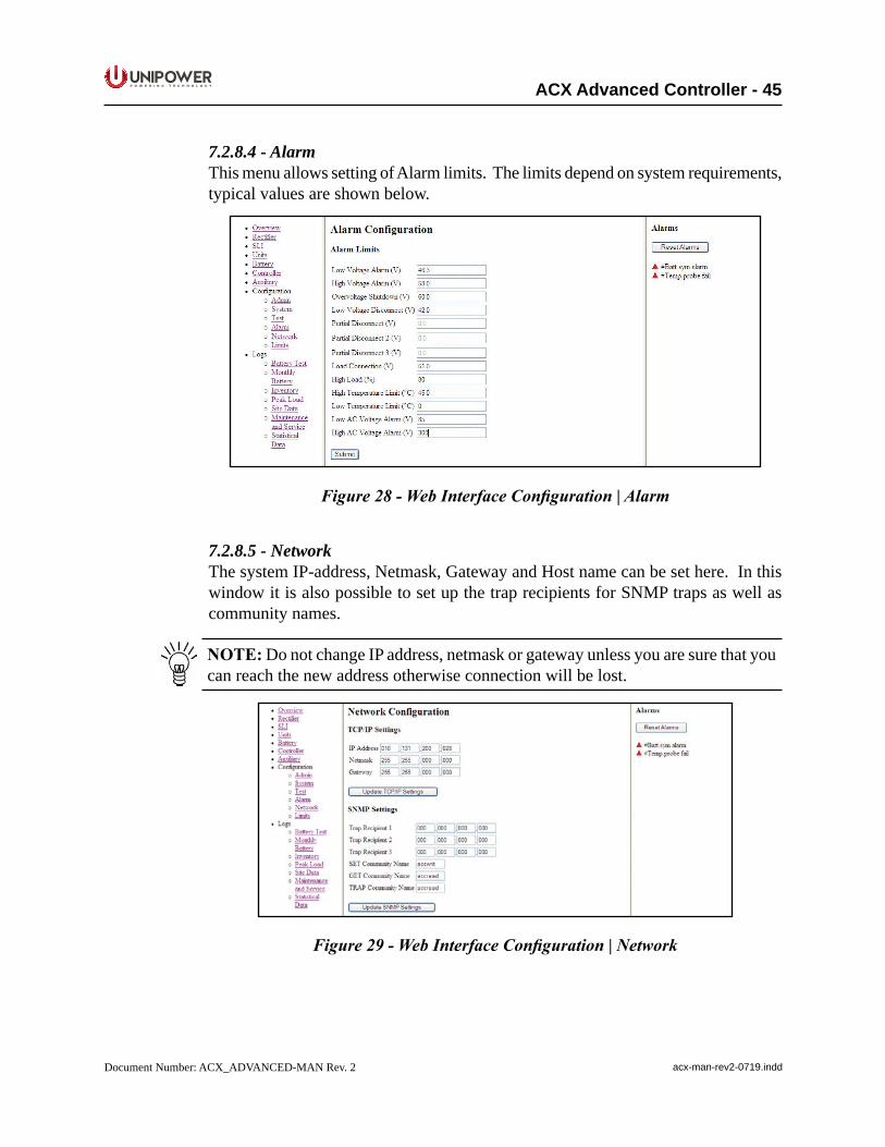
P O W E R I N G T E C H N O L O G Y
Document Number: ACX_ADVANCED-MAN Rev. 2 acx-man-rev2-0719.indd
ACX Advanced Controller - 45
7.2.8.4 - AlarmThis menu allows setting of Alarm limits. The limits depend on system requirements, typical values are shown below.
Figure 28 - Web Interface Configuration | Alarm
7.2.8.5 - NetworkThe system IP-address, Netmask, Gateway and Host name can be set here. In this window it is also possible to set up the trap recipients for SNMP traps as well as community names.
NOTE: Do not change IP address, netmask or gateway unless you are sure that you can reach the new address otherwise connection will be lost.
Figure 29 - Web Interface Configuration | Network
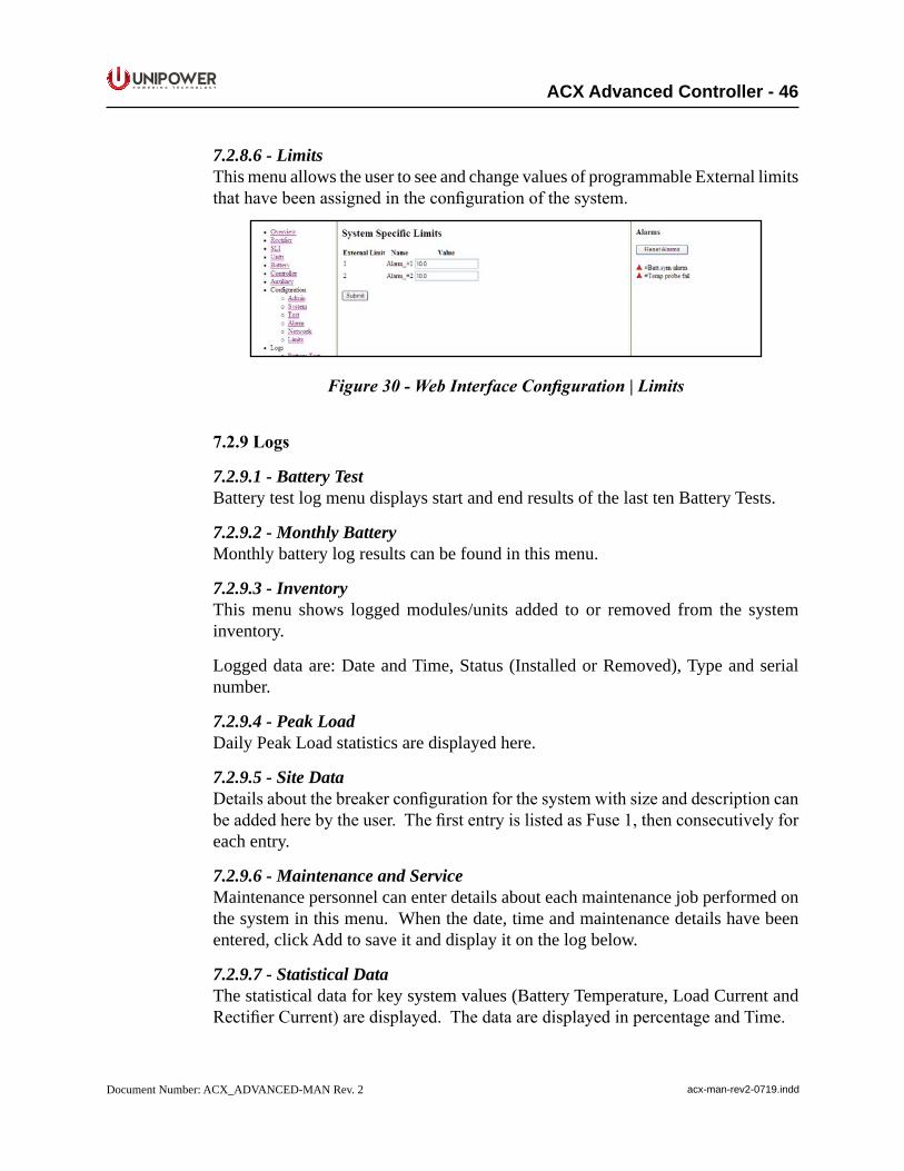
P O W E R I N G T E C H N O L O G Y
Document Number: ACX_ADVANCED-MAN Rev. 2 acx-man-rev2-0719.indd
ACX Advanced Controller - 46
7.2.8.6 - LimitsThis menu allows the user to see and change values of programmable External limits thathavebeenassignedintheconfigurationofthesystem.
Figure 30 - Web Interface Configuration | Limits
7.2.9Logs
7.2.9.1 - Battery TestBattery test log menu displays start and end results of the last ten Battery Tests.
7.2.9.2 - Monthly BatteryMonthly battery log results can be found in this menu.
7.2.9.3 - InventoryThis menu shows logged modules/units added to or removed from the system inventory.
Logged data are: Date and Time, Status (Installed or Removed), Type and serial number.
7.2.9.4 - Peak LoadDaily Peak Load statistics are displayed here.
7.2.9.5 - Site DataDetailsaboutthebreakerconfigurationforthesystemwithsizeanddescriptioncanbeaddedherebytheuser.ThefirstentryislistedasFuse1,thenconsecutivelyforeach entry.
7.2.9.6 - Maintenance and ServiceMaintenance personnel can enter details about each maintenance job performed on the system in this menu. When the date, time and maintenance details have been entered, click Add to save it and display it on the log below.
7.2.9.7 - Statistical DataThe statistical data for key system values (Battery Temperature, Load Current and RectifierCurrent)aredisplayed.ThedataaredisplayedinpercentageandTime.
P O W E R I N G T E C H N O L O G Y
Document Number: ACX_ADVANCED-MAN Rev. 2 acx-man-rev2-0719.indd
ACX Advanced Controller - 47
NOTE: The total percentage may not always be 100 as the values are rounded down to the nearest integer.
P O W E R I N G T E C H N O L O G Y
Document Number: ACX_ADVANCED-MAN Rev. 2 acx-man-rev2-0719.indd
ACX Advanced Controller - 48
8. SNMPSimple Network Management Protocol (SNMP) is an Internet standard protocol for management of network devices. SNMP Management systems can supervise a variety ofnetworkedequipmentsimplybyimportingafilewithdefinitionsoftheManagementInformation Base (MIB). The SNMP Manager program can access and control the UNIPOWER power systems by adding the MIB describing the controller manageable objects toitscollectionofMIBfiles.
The controller implements SNMPv3 as well SNMPv1/2c. The user can select which SNMP protocol will be used, SNMPv1/SNMPv2c or SNMPv3. The available MIB objects are common for both SNMP versions with the exception of security parameters for SNMPv3. If SNMPv3 is selected, the controller does not respond to SNMPv1/2c commands and vice-versa.
SNMPv1/2c uses security parameters called community name. The controller recognizes three community names:
• SET community name (default value is accwrit)• GET community name (default value is accread)• TRAP community name (default value is accread)
Values for the community name can be changed via the web interface. Additionally the TRAP community name can also be changed via SNMP. The maximum length allowed for community names is 15 characters.
8.1 MIBTheMIBforthepowersystemisaprivate,enterprisespecificMIB.Itdefinesanumber of manageable objects including:
BasicSystemInformation• System Name• Controller Type• Controller Software Version• Controller Serial Number
OperationalState• System Voltage• Load Current• Battery Current• RectifierCurrent• Battery Temperature• AC Input Phase Voltage• Remaining Battery Time• Alarms• Tables with Power Module Information (AC/DC, DC/DC and SLI)
P O W E R I N G T E C H N O L O G Y
Document Number: ACX_ADVANCED-MAN Rev. 2 acx-man-rev2-0719.indd
ACX Advanced Controller - 49
NOTE:Ifthe4x64multiplexerboardisused,therectifiertabledisplaysdataonlyfor the selected channel. Channel selection can be changed by setting value of the selectChannel MIB variable. Refreshing data of the newly selected channel requires some time (2 - 3 seconds). This has to be considered when automatic pooling of rectifiertableisperformed.
• Battery Symmetry Table
SystemParametersSetting• Voltage References• Battery Current Limiting• Temperature Compensation• Alarms Limits• Battery Test
SNMPAgentSetting• Community Names• TrapRecipients(Upto8recipientscanbedefined)• SNMPv3 User Parameters
NOTE:ForfulllistofavailableobjectsseeACX-MIB.mibfile.YoucandownloadthelatestACX-MIB.mibfilefromhttps://www.unipowerco.com/MIB_files/ACX-MIB.mib.(saveastextfilewithout.txtextensiononceopenedinbrowser.)
Tip: Alarm data 1-3, Ext Alarm data 1-2 and Status bytes 1-4 objects in the ACX MIB are bit patterns that contain the current alarm status etc. See the following table for details.
Table 1 - Alarm Data
Bit Description CommentAlarm data 1
0 Low voltage alarm1 High voltage alarm2 Low voltage disconnect Ref: Battery/Load disconnected alarm3 Mains failure4 Distribution fuse failure Ref: Load breaker failure5 Low AC Voltage6 Battery failure7 Rectifier module alarm
Alarm data 20 High temperature alarm1 Symmetry failure2 Battery fuse failure3 High Load alarm4 High AC Voltage
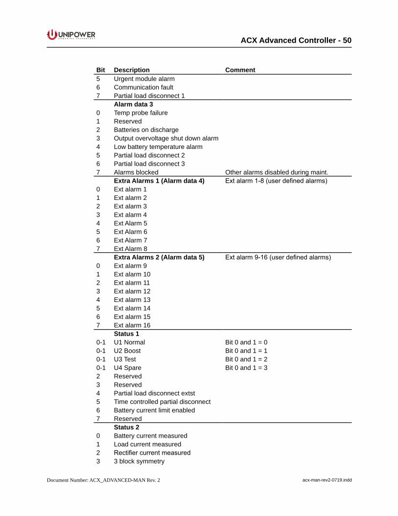
P O W E R I N G T E C H N O L O G Y
Document Number: ACX_ADVANCED-MAN Rev. 2 acx-man-rev2-0719.indd
ACX Advanced Controller - 50
Bit Description Comment5 Urgent module alarm6 Communication fault7 Partial load disconnect 1
Alarm data 30 Temp probe failure1 Reserved2 Batteries on discharge3 Output overvoltage shut down alarm4 Low battery temperature alarm5 Partial load disconnect 26 Partial load disconnect 37 Alarms blocked Other alarms disabled during maint.
Extra Alarms 1 (Alarm data 4) Ext alarm 1-8 (user defined alarms)0 Ext alarm 11 Ext alarm 22 Ext alarm 33 Ext alarm 44 Ext Alarm 55 Ext Alarm 66 Ext Alarm 77 Ext Alarm 8
Extra Alarms 2 (Alarm data 5) Ext alarm 9-16 (user defined alarms)0 Ext alarm 91 Ext alarm 102 Ext alarm 113 Ext alarm 124 Ext alarm 135 Ext alarm 146 Ext alarm 157 Ext alarm 16
Status 10-1 U1 Normal Bit 0 and 1 = 00-1 U2 Boost Bit 0 and 1 = 10-1 U3 Test Bit 0 and 1 = 20-1 U4 Spare Bit 0 and 1 = 32 Reserved3 Reserved4 Partial load disconnect extst5 Time controlled partial disconnect6 Battery current limit enabled7 Reserved
Status 20 Battery current measured1 Load current measured2 Rectifier current measured3 3 block symmetry
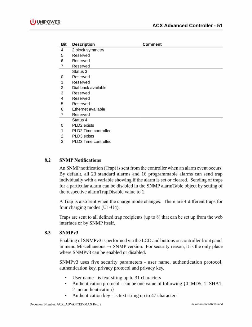
P O W E R I N G T E C H N O L O G Y
Document Number: ACX_ADVANCED-MAN Rev. 2 acx-man-rev2-0719.indd
ACX Advanced Controller - 51
Bit Description Comment4 2 block symmetry5 Reserved6 Reserved7 Reserved
Status 30 Reserved1 Reserved2 Dial back available3 Reserved4 Reserved5 Reserved6 Ethernet available7 Reserved
Status 40 PLD2 exists1 PLD2 Time controlled2 PLD3 exists3 PLD3 Time controlled
8.2 SNMPNotificationsAnSNMPnotification(Trap)issentfromthecontrollerwhenanalarmeventoccurs.By default, all 23 standard alarms and 16 programmable alarms can send trap individually with a variable showing if the alarm is set or cleared. Sending of traps for a particular alarm can be disabled in the SNMP alarmTable object by setting of the respective alarmTrapDisable value to 1.
ATrapisalsosentwhenthechargemodechanges.Thereare4differenttrapsforfour charging modes (U1-U4).
Trapsaresenttoalldefinedtraprecipients(upto8)thatcanbesetupfromthewebinterface or by SNMP itself.
8.3 SNMPv3Enabling of SNMPv3 is performed via the LCD and buttons on controller front panel inmenuMiscellaneous→SNMPversion.Forsecurityreason,itistheonlyplacewhere SNMPv3 can be enabled or disabled.
SNMPv3 uses five security parameters - user name, authentication protocol, authentication key, privacy protocol and privacy key.
• User name - is text string up to 31 characters• Authentication protocol - can be one value of following {0=MD5, 1=SHA1,
2=no authentication}• Authentication key - is text string up to 47 characters
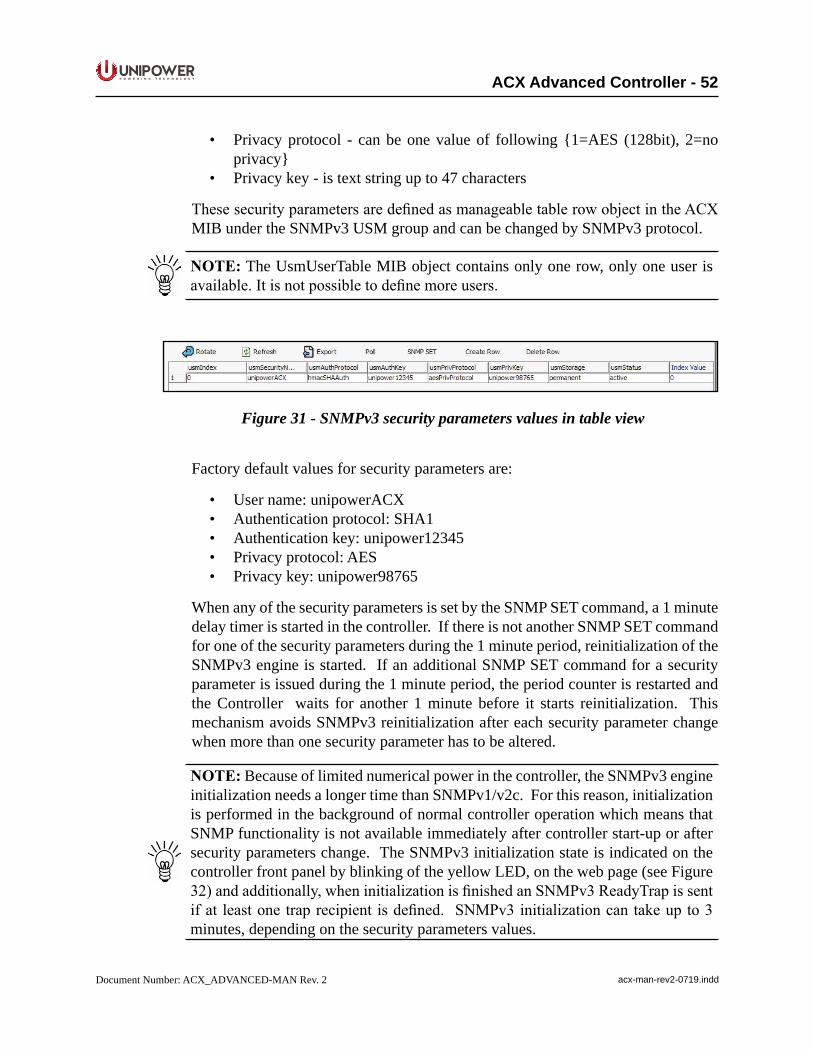
P O W E R I N G T E C H N O L O G Y
Document Number: ACX_ADVANCED-MAN Rev. 2 acx-man-rev2-0719.indd
ACX Advanced Controller - 52
• Privacy protocol - can be one value of following {1=AES (128bit), 2=no privacy}
• Privacy key - is text string up to 47 characters
ThesesecurityparametersaredefinedasmanageabletablerowobjectintheACXMIB under the SNMPv3 USM group and can be changed by SNMPv3 protocol.
NOTE: The UsmUserTable MIB object contains only one row, only one user is available.Itisnotpossibletodefinemoreusers.
Figure 31 - SNMPv3 security parameters values in table view
Factory default values for security parameters are:
• User name: unipowerACX• Authentication protocol: SHA1• Authentication key: unipower12345• Privacy protocol: AES• Privacy key: unipower98765
When any of the security parameters is set by the SNMP SET command, a 1 minute delay timer is started in the controller. If there is not another SNMP SET command for one of the security parameters during the 1 minute period, reinitialization of the SNMPv3 engine is started. If an additional SNMP SET command for a security parameter is issued during the 1 minute period, the period counter is restarted and the Controller waits for another 1 minute before it starts reinitialization. This mechanism avoids SNMPv3 reinitialization after each security parameter change when more than one security parameter has to be altered.
NOTE: Because of limited numerical power in the controller, the SNMPv3 engine initialization needs a longer time than SNMPv1/v2c. For this reason, initialization is performed in the background of normal controller operation which means that SNMP functionality is not available immediately after controller start-up or after security parameters change. The SNMPv3 initialization state is indicated on the controller front panel by blinking of the yellow LED, on the web page (see Figure 32)andadditionally,wheninitializationisfinishedanSNMPv3ReadyTrapissentifat leastonetraprecipient isdefined. SNMPv3initializationcantakeupto3minutes, depending on the security parameters values.
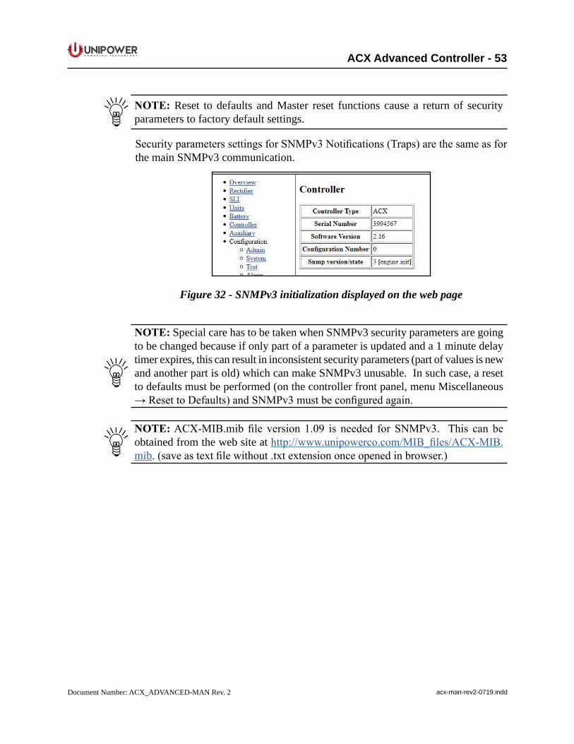
P O W E R I N G T E C H N O L O G Y
Document Number: ACX_ADVANCED-MAN Rev. 2 acx-man-rev2-0719.indd
ACX Advanced Controller - 53
NOTE: Reset to defaults and Master reset functions cause a return of security parameters to factory default settings.
SecurityparameterssettingsforSNMPv3Notifications(Traps)arethesameasforthe main SNMPv3 communication.
Figure 32 - SNMPv3 initialization displayed on the web page
NOTE: Special care has to be taken when SNMPv3 security parameters are going to be changed because if only part of a parameter is updated and a 1 minute delay timer expires, this can result in inconsistent security parameters (part of values is new and another part is old) which can make SNMPv3 unusable. In such case, a reset to defaults must be performed (on the controller front panel, menu Miscellaneous →ResettoDefaults)andSNMPv3mustbeconfiguredagain.
NOTE:ACX-MIB.mibfile version 1.09 is needed forSNMPv3. This can beobtained from the web site at http://www.unipowerco.com/MIB_files/ACX-MIB.mib.(saveastextfilewithout.txtextensiononceopenedinbrowser.)
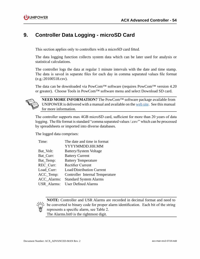
P O W E R I N G T E C H N O L O G Y
Document Number: ACX_ADVANCED-MAN Rev. 2 acx-man-rev2-0719.indd
ACX Advanced Controller - 54
9. Controller Data Logging - microSD Card
ThissectionappliesonlytocontrollerswithamicroSDcardfitted.
The data logging function collects system data which can be later used for analysis or statistical calculations.
The controller logs the data at regular 1 minute intervals with the date and time stamp. Thedata is saved in separatefiles for eachday in comma separatedvaluesfile format(e.g.:20100518.csv).
The data can be downloaded via PowCom™ software (requires PowCom™ version 4.20 or greater). Choose Tools in PowCom™ software menu and select Download SD card.
NEEDMOREINFORMATION? The PowCom™ software package available from UNIPOWER is delivered with a manual and available on the web site. See this manual for more information.
Thecontrollersupportsmax4GBmicroSDcard,sufficientformorethan20yearsofdatalogging.Thefileformatisstandard“commaseparatedvalues/.csv/”whichcanbeprocessedby spreadsheets or imported into diverse databases.
The logged data comprises:
Time: The date and time in format YYYYMMDD.HH.MMBat_Volt: Battery/System VoltageBat_Curr: Battery CurrentBat_Temp: Battery TemperatureREC_Curr: RectifierCurrentLoad_Curr: Load/Distribution CurrentACC_Temp: Controller Internal TemperatureACC_Alarms: Standard System AlarmsUSR_Alarms: UserDefinedAlarms
NOTE: Controller and USR Alarms are recorded in decimal format and need to beconvertedtobinarycodeforproperalarmidentification.Eachbitofthestringrepresentsaspecificalarm,seeTable2.The Alarms.bit0 is the rightmost digit.
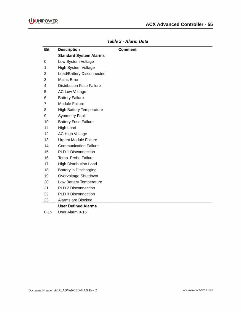
P O W E R I N G T E C H N O L O G Y
Document Number: ACX_ADVANCED-MAN Rev. 2 acx-man-rev2-0719.indd
ACX Advanced Controller - 55
Table 2 - Alarm Data
Bit Description CommentStandard System Alarms
0 Low System Voltage1 High System Voltage2 Load/Battery Disconnected3 Mains Error4 Distribution Fuse Failure5 AC Low Voltage6 Battery Failure7 Module Failure8 High Battery Temperature9 Symmetry Fault10 Battery Fuse Failure11 High Load12 AC High Voltage13 Urgent Module Failure14 Communication Failure15 PLD 1 Disconnection16 Temp. Probe Failure17 High Distribution Load18 Battery is Discharging19 Overvoltage Shutdown20 Low Battery Temperature21 PLD 2 Disconnection22 PLD 3 Disconnection23 Alarms are Blocked
UserDefinedAlarms0-15 User Alarm 0-15
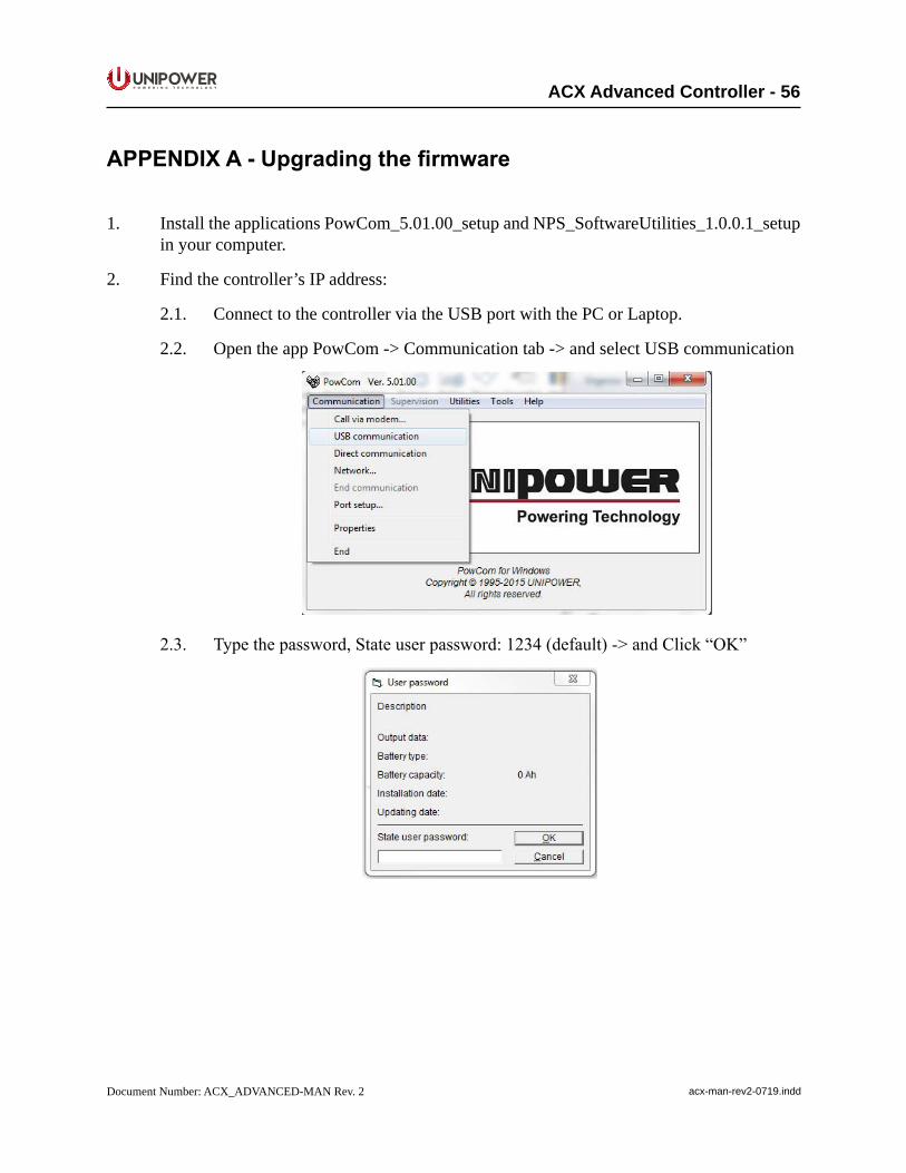
P O W E R I N G T E C H N O L O G Y
Document Number: ACX_ADVANCED-MAN Rev. 2 acx-man-rev2-0719.indd
ACX Advanced Controller - 56
APPENDIXA-Upgradingthefirmware
1. Install the applications PowCom_5.01.00_setup and NPS_SoftwareUtilities_1.0.0.1_setup in your computer.
2. Find the controller’s IP address:
2.1. Connect to the controller via the USB port with the PC or Laptop.
2.2. Open the app PowCom -> Communication tab -> and select USB communication
2.3. Typethepassword,Stateuserpassword:1234(default)->andClick“OK”
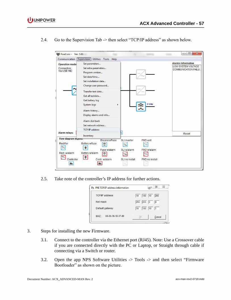
P O W E R I N G T E C H N O L O G Y
Document Number: ACX_ADVANCED-MAN Rev. 2 acx-man-rev2-0719.indd
ACX Advanced Controller - 57
2.4. GototheSupervisionTab->thenselect“TCP/IPaddress”asshownbelow.
2.5. Take note of the controller’s IP address for further actions.
3. Steps for installing the new Firmware.
3.1. Connect to the controller via the Ethernet port (RJ45). Note: Use a Crossover cable if you are connected directly with the PC or Laptop, or Straight through cable if connecting via a Switch or router.
3.2. Open the app NPS Software Utilities -> Tools -> and then select “Firmware Bootloader”asshownonthepicture.
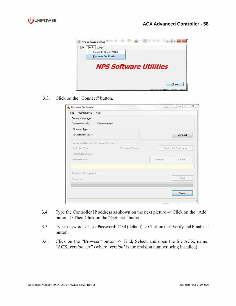
P O W E R I N G T E C H N O L O G Y
Document Number: ACX_ADVANCED-MAN Rev. 2 acx-man-rev2-0719.indd
ACX Advanced Controller - 58
3.3. Clickonthe“Connect”button.
3.4. TypetheControllerIPaddressasshownonthenextpicture->Clickonthe“Add”button->ThenClickonthe“GetList”button.
3.5. Typepassword->UserPassword:1234(default)->Clickonthe“VerifyandFinalize”button.
3.6. Click on the “Browser” button ->Find, Select, and open thefileACX, name:“ACX_version.acx”(where‘version’ is the revision number being installed).
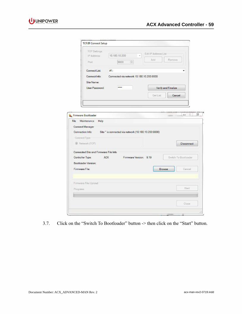
P O W E R I N G T E C H N O L O G Y
Document Number: ACX_ADVANCED-MAN Rev. 2 acx-man-rev2-0719.indd
ACX Advanced Controller - 59
3.7. Clickonthe“SwitchToBootloader”button->thenclickonthe“Start”button.
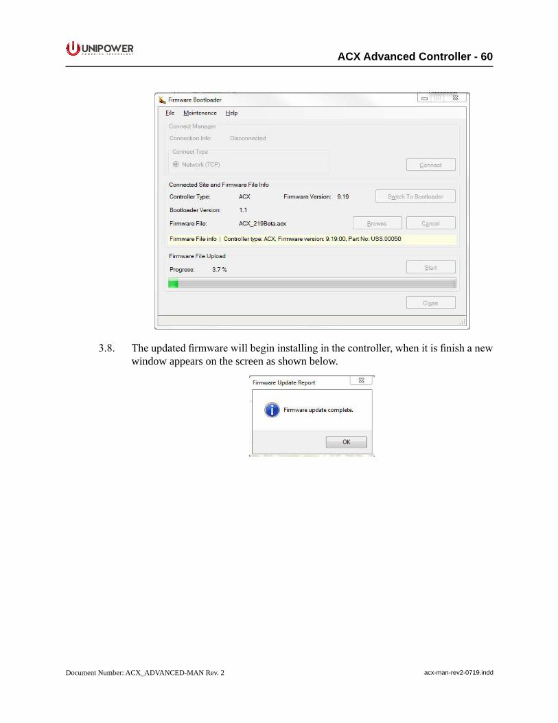
P O W E R I N G T E C H N O L O G Y
Document Number: ACX_ADVANCED-MAN Rev. 2 acx-man-rev2-0719.indd
ACX Advanced Controller - 60
3.8. Theupdatedfirmwarewillbegininstallinginthecontroller,whenitisfinishanewwindow appears on the screen as shown below.
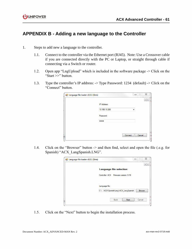
P O W E R I N G T E C H N O L O G Y
Document Number: ACX_ADVANCED-MAN Rev. 2 acx-man-rev2-0719.indd
ACX Advanced Controller - 61
APPENDIX B - Adding a new language to the Controller
1. Steps to add new a language to the controller.
1.1. Connect to the controller via the Ethernet port (RJ45). Note: Use a Crossover cable if you are connected directly with the PC or Laptop, or straight through cable if connecting via a Switch or router.
1.2. Openapp“LngUpload”whichisincludedinthesoftwarepackage->Clickonthe“Start>>”button.
1.3. Type the controller’s IP address: -> Type Password: 1234 (default) -> Click on the “Connect”button.
1.4. Clickonthe“Browser”button->andthenfind,selectandopenthefile(.e.g.forSpanish)“ACX_LangSpanish.LNG”.
1.5. Clickonthe“Next”buttontobegintheinstallationprocess.
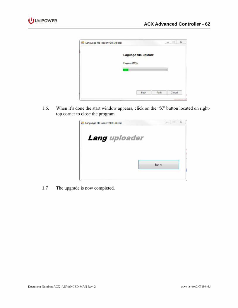
P O W E R I N G T E C H N O L O G Y
Document Number: ACX_ADVANCED-MAN Rev. 2 acx-man-rev2-0719.indd
ACX Advanced Controller - 62
1.6. Whenit’sdonethestartwindowappears,clickonthe“X”buttonlocatedonright-top corner to close the program.
1.7 The upgrade is now completed.
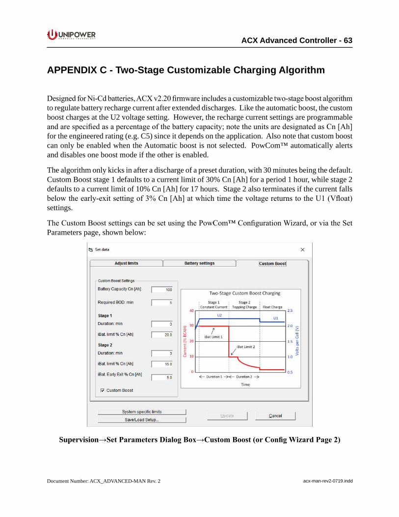
P O W E R I N G T E C H N O L O G Y
Document Number: ACX_ADVANCED-MAN Rev. 2 acx-man-rev2-0719.indd
ACX Advanced Controller - 63
APPENDIX C - Two-Stage Customizable Charging Algorithm
DesignedforNi-Cdbatteries,ACXv2.20firmwareincludesacustomizabletwo-stageboostalgorithmto regulate battery recharge current after extended discharges. Like the automatic boost, the custom boost charges at the U2 voltage setting. However, the recharge current settings are programmable andarespecifiedasapercentageofthebatterycapacity;notetheunitsaredesignatedasCn[Ah]for the engineered rating (e.g. C5) since it depends on the application. Also note that custom boost can only be enabled when the Automatic boost is not selected. PowCom™ automatically alerts and disables one boost mode if the other is enabled.
The algorithm only kicks in after a discharge of a preset duration, with 30 minutes being the default. Custom Boost stage 1 defaults to a current limit of 30% Cn [Ah] for a period 1 hour, while stage 2 defaults to a current limit of 10% Cn [Ah] for 17 hours. Stage 2 also terminates if the current falls belowtheearly-exitsettingof3%Cn[Ah]atwhichtimethevoltagereturnstotheU1(Vfloat)settings.
TheCustomBoostsettingscanbesetusingthePowCom™ConfigurationWizard,orviatheSetParameters page, shown below:
Supervision→SetParametersDialogBox→CustomBoost(orConfigWizardPage2)
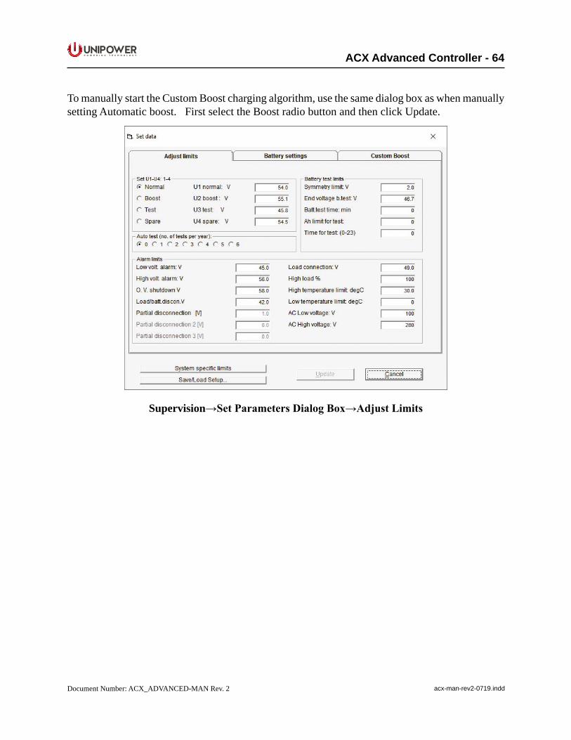
P O W E R I N G T E C H N O L O G Y
Document Number: ACX_ADVANCED-MAN Rev. 2 acx-man-rev2-0719.indd
ACX Advanced Controller - 64
To manually start the Custom Boost charging algorithm, use the same dialog box as when manually setting Automatic boost. First select the Boost radio button and then click Update.
Supervision→SetParametersDialogBox→AdjustLimits
P O W E R I N G T E C H N O L O G Y
Document Number: ACX_ADVANCED-MAN Rev. 2 acx-man-rev2-0719.indd
ACX Advanced Controller - 65
PRODUCT SUPPORT
Product support can be obtained using the following addresses and telephone numbers.
Corporateoffice:UNIPOWER, LLC210 N University DrCoral Springs, FL 33071 United States
Manufacturing facility:UNIPOWER, LLC65 Industrial Park RdDunlap, TN 37327United States
Manufacturing facility:UNIPOWER Slovakia SRO ZLATOVSKA 1279 Business Center 2291105 Trencin, Slovakia
Phone: +1-954-346-2442Toll Free: 1-800-440-3504Web site – www.unipowerco.com
When contacting UNIPOWER, please be prepared to provide:
1. The product model number, spec number, S build number, and serial number - see the equipment nameplate on the front panel2. Your company’s name and address3. Your name and title4. The reason for the contact5. If there is a problem with product operation:
• Is the problem intermittent or continuous?• Whatrevisionisthefirmware?• What actions were being performed prior to the appearance of the problem?• What actions have been taken since the problem occurred?