installation & operating manualliveantares.com/wp-content/uploads/2016/12/adlerbarbour.pdf ·...
TRANSCRIPT

Contents, specifications and availability are subject to change without notice. Tel. (860) 664-4911 • Fax. (860) 664-4912 • www.waecousa.com WAECO USA, Inc. 1WAECO USA • Clinton, CT • www.waecousa.com
Installation &Operating Manual
› For ADLER/BARBOUR SERIESColdMachine™SuperColdMachine™It’s a perfect mate!

2 WAECO USA, Inc. Tel. (860) 664-4911 • Fax. (860) 664-4912 • www.waecousa.com Contents, specifications and availability are subject to change without notice.
IMPORTANT NOTICEBefore you proceed, please read this manual from cover to cover.
Failure to following instructions may void your warranty.
Introduction . . . . . . . . . . . . . . . . . . . . . . . . . . . . . . . . . . . . . .3Terminology . . . . . . . . . . . . . . . . . . . . . . . . . . . . . . . . . . . . . .3Unpacking Equipment . . . . . . . . . . . . . . . . . . . . . . . . . . . . . .4Tools & Equipment Needed for Installation . . . . . . . . . . . . . .4
Planning the Condensing Unit Installation . . . . . . . . . . . . .4Ventilation Requirements . . . . . . . . . . . . . . . . . . . . . . . . . . . .4Duct Kits and Power Duct Kits . . . . . . . . . . . . . . . . . . . . . . . .5Location Considerations . . . . . . . . . . . . . . . . . . . . . . . . . . . . .5
Mounting the Condensing Unit . . . . . . . . . . . . . . . . . . . . . . .6
Planning the Evaporator Installation . . . . . . . . . . . . . . . . . .6Evaporator Location Choices - Vertical Applications . . . . . . . .6Optional Box Modifications & Combinations . . . . . . . . . . . .7–8Horizontal Applications . . . . . . . . . . . . . . . . . . . . . . . . . . . . . .8
Mounting the Evaporator . . . . . . . . . . . . . . . . . . . . . . . . . . .9Refrigerant Couplings . . . . . . . . . . . . . . . . . . . . . . . . . . .10–12Installing the Analog Thermostat . . . . . . . . . . . . . . . . . . . . .13Installing the Digital Thermostat . . . . . . . . . . . . . . . . . . . . .14Mounting the PowerPlate . . . . . . . . . . . . . . . . . . . . . . . . . .15
Electrical Considerations . . . . . . . . . . . . . . . . . . . . . . . . . . .16
Water Cooled Optional Package/Installation . . . . . . . . . . .17Battery Recommendations . . . . . . . . . . . . . . . . . . . . . . . . . .18Wiring the System . . . . . . . . . . . . . . . . . . . . . . . . . . . . . . . .18Voltage Drops . . . . . . . . . . . . . . . . . . . . . . . . . . . . . . . . . . . .19Making the Power Connections . . . . . . . . . . . . . . . . . . . . . .19Wire Size and Wire Size Table . . . . . . . . . . . . . . . . . . . . . . .19Wiring Diagrams . . . . . . . . . . . . . . . . . . . . . . . . . . . . . . .20–23
Operation of System . . . . . . . . . . . . . . . . . . . . . . . . . . . . . .24Start-Up . . . . . . . . . . . . . . . . . . . . . . . . . . . . . . . . . . . . . . . .24AC/DC Operation . . . . . . . . . . . . . . . . . . . . . . . . . . . . . . . . .24Maintenance . . . . . . . . . . . . . . . . . . . . . . . . . . . . . . . . . . . .24Defrosting . . . . . . . . . . . . . . . . . . . . . . . . . . . . . . . . . . . . . . .24Battery Care . . . . . . . . . . . . . . . . . . . . . . . . . . . . . . . . . . . . .24Winter Operation . . . . . . . . . . . . . . . . . . . . . . . . . . . . . . . . .25
Programming Digital Control . . . . . . . . . . . . . . . . . . . . . . .25To Program Set Point . . . . . . . . . . . . . . . . . . . . . . . . . . . . . .25To Program Differential . . . . . . . . . . . . . . . . . . . . . . . . . . . .25
Electronic Module Protection System . . . . . . . . . . . . . . . . .26
Operational Errors Indicated by LED on Condensing Unit . . . . . . . . . . . . . . . . . . . . . . . . . . . . . . .26
Troubleshooting Guide . . . . . . . . . . . . . . . . . . . . . . . . . .27–29
Procedure for Removing Compressor Unit . . . . . . . . . . . . .30
Procedure for Removing Evaporator & Tubeset . . . . . . . . .30
Procedure for Removing PowerPlate & Tube Set . . . . . . . .30
Warranty . . . . . . . . . . . . . . . . . . . . . . . . . . . . . . . . . . . . . . .31
Return Policy . . . . . . . . . . . . . . . . . . . . . . . . . . . . . . . . . . . .31
ColdMachine™
SuperColdMachine™
This manual covers:All air-cooled ColdMachine™ products and all air/water-cooled SuperColdMachine™ products with:
• Standard aluminum “bin” shaped evaporators• Custom formed “flat”, “L”, “U” shaped evaporators• PowerPlate stainless steel holdover evaporators• Analog type thermostatic controls (standard)• Digital type thermostatic controls (optional)

Contents, specifications and availability are subject to change without notice. Tel. (860) 664-4911 • Fax. (860) 664-4912 • www.waecousa.com WAECO USA, Inc. 3
INTRODUCTION
Thank you for purchasing your new ADLER/BARBOUR marinerefrigeration system. This manual will explain how to install thesystem on your boat—in just a few hours—with ordinary tools.
NOTE: This system is charged with HFC134 a non-ozone depletingrefrigerant. Please refer to the TROUBLESHOOTING AND SERVICESECTION of this manual for more details.
VARIABLE CAPACITY COMPRESSOR WITH LOAD MATCHINGCommnecing February 2000, all ADLER/BARBOUR products areequipped with the most advanced DC compressor ever—theDanfoss BD50F. Its wider performance range enables us toprecisely match the compressor speed and capacity to the job itmust do, while still keeping power consumption to a minimum.This means:
For the largest refrigerators, and for all freezer applications,the compressor operates at maximum 3500 RPM, producingapproximately 25% higher performance than previous BD35Fcompressor.
For mid-sized refrigerators, and for most freezer applications,the compressor operates at 3000 RPM, with about 15% higherperformance than previous models.
For smaller refrigerator applications using our VD-150 andVD-151 systems, the compressor will operate at 2500 RPM—stilldelivering slightly higher performance than previously.
For every application, the BD50F-based ADLER/BARBOURproducts deliver top efficiency with minimal power consumption.
TERMINOLOGYBelow are terms and definitions that will be used throughout thismanual:
CONDENSING UNIT:The stainless steel base plate mounted compressor, electronic control module, electrical housing and terminal block,refrigerant couplings, air-cooled condenser and shroud (thecondensing unit comes precharged with R134a refrigerant).Condensing units may be:
• ColdMachine™ (air-cooled only)
• SuperColdMachine™ (air/water-cooled)
EVAPORATOR:Also referred to as “the freezer”, this is the formed aluminum “bin” (or custom-formed “L”, “U”, or “flat”) withconnecting tubeset and couplings (also precharged with R134arefrigerant). Mounts inside the space to be refrigerated.
PowerPlate:The flat, stainless steel, holdover plate-type evaporator(precharged with R134a refrigerant). Mounts inside the space tobe refrigerated.
Tubeset:The copper refrigerant tubing and couplings, also precharged withR134a refrigerant. Tubesets may come attached (evaporators) orseparate (PowerPlates).
Thermostatic Control (T’stat):May be analog (knob) type or digital (LED display) type.
Cabinet, Box, Icebox, Compartment:The insulated space that will be converted into a mechanicalrefrigerator, freezer, or combination refrigerator/freezer.
LED:Light Emitting Diode. Mounted in the junction box, used fordiagnostics.
Electronic Module:The housing attached to the compressor provides complete digitalsystem management.
Junction Box:The stainless steel housing with terminal block, LED, t’stat harnesssocket, fuses and relay.
ColdMachine™:The term “ColdMachine” is used throughout this manual whenreferring to the condensing unit (whether air cooled only ofair/water cooled).

4 WAECO USA, Inc. Tel. (860) 664-4911 • Fax. (860) 664-4912 • www.waecousa.com Contents, specifications and availability are subject to change without notice.
UNPACKING THE EQUIPMENTWhen unpacking the unit, carefully check for shipping damage and identify all listed items to ensure that all components have been received and that no in-transit damage has occurred. File claims for loss or damage directly withthe carrier. If the system was purchased through a dealer, please contact the dealer directly.
All ADLER/BARBOUR refrigeration systems include the following:
• Condensing unit
• Evaporator assembly (either aluminum with integral tube setor PowerPlate with separate tube set)
• Ice cube trays, vertical or horizontal to suit: 2 for smallevaporators, 3 for large evaporators (trays are not included with PowerPlate systems)
• Separator to retain ice cube trays (vertical style only)
• Thermostatic control (either digital with wire harness oranalog (knob type) with wire harness)
• Installation / small parts package
• Template for evaporator mounting hole locations (exceptPowerPlate systems)
• Soft-sealing removable mastic putty (“Mortite”) for tubing exithole through box (never use the durable marine type)
TOOLS AND EQUIPMENTNEEDED FOR INSTALLATION
• Electric drill with assorted small bits including 9/64”
• Stubby Phillips screwdriver
• Hole saw 1-1/2” diameter
• Wrench, open end type, 5/8”
• Wrench, open end type, 13/16”
• Wrench, open end type for powerplate, 3/4”
• Electrical wire, 2 conductor, marine type tinned flexible copperstranded (see Wire Size Table in this manual)
*Alternatively, two (2) adjustable wrenches, 10” size
PLANNING THE CONDENSING UNIT INSTALLATION
Please keep the following points in mind when planning theinstallation.
GENERAL
• The connecting refrigerant tube set between the condensingunit and the freezer is 15’ long (12.5’ for PowerPlate). Planthe location of the two units accordingly.
• The route of the refrigerant tube set through the boat fromthe condensing unit to the icebox must be determined beforestarting any work. The tube set must be kept clear of anybilge water and protected from the chafe and damage.
• Ventilation openings or ventilation duct options will berequired if the compressor unit is located in a small, confinedcompartment. Re-circulating the same is unacceptable.
• Engine room location for the air condensing unit is okay if thecontinuous environment is not over 100°F, but performancewill be much improved is a Duct Kit or Power Duct Kit isinstalled to provide inlet air at under 90°F. A cooler location = less running time = lower amperage draw.
• Accessibility is an important consideration.
• All components must be protected from bilge water, spray or possible physical damage.
VENTILATION REQUIREMENTS
The ColdMachine is a device that moves heat from one place toanother. It does not “create cold.” The heat removed from youricebox by way of the evaporator is transferred to the air aroundthe condensing unit. If you locate the condensing unit in a small,hot or confined enclosure, it will suffocate. Its built-in fan willhave to re-circulate hotter air. It will run continuously, drawexcess amps and not cool efficiently. It will never shut off and itsperformance will be unacceptable.
Let the unit breathe! Position the condensing unit so that its fancan intake air from one space and discharge it to another. Do notre-circulate the same air unless the compartment in which youmount the unit is 100 cubic feet or larger in volume,unobstructed, and mostly below the waterline.

Contents, specifications and availability are subject to change without notice. Tel. (860) 664-4911 • Fax. (860) 664-4912 • www.waecousa.com WAECO USA, Inc. 5
DUCT KITS AND POWERDUCT KITS
To achieve cool airflow through your ColdMachine, we offer fourdifferent packages to improve ventilation:
FOR THE COLDMACHINE:
Part # C8079Ventilation Duct Kit with adapter shroud, 3 ft. of 4” flex duct, 1adapter flange and trim grille. Attaches to the condensing unitwith four screws. Can be used in two ways:
(1) To bring air to the unit from a cooler location—bilge, yachtaccommodation, cool ventilated locker, etc., or
(2) The condensing unit’s fan can be physically reversed and theduct kit can be used to extract air from the unit and dischargeit into another space. This is preferred if the location has coolair available, but has no way to get rid of the warmer air afterit has passed through the condensing unit.
Part # C8075Power Duct Booster Duct Kit—as above, with 5 feet of 4” flexduct, 3 adapter flanges and additional booster fan. Used exactlylike above, plus the longer length and push-pull fans” allow youto go to a greater distance through the boat to pick up cool air orget rid of heated air.
FOR THE SUPERCOLDMACHINE:
Part # C8070Ventilation Duct Kit with 3 ft of flex duct, 1 adapter flange andtrim grille. Attaches to the SuperColdMachine condensing unitwith 4 existing fan mount screws. Can be used in 2 ways:
(1) To bring air to the unit from a cooler location—bilge, yachtaccommodation, cool ventilated locker, etc., or
(2) The condensing unit’s fan can be physically reversed and theduct kit can be used to extract air from the unit and dischargeit into another space. This is preferred if the location has coolair available, but has no way to get rid of the warmer air afterit has passed through the condensing unit.
Part # C8071Power Duct Booster Duct Kit—as above, with 5 feet of 4” flexduct, 3 adapter flanges and additional booster fan. Used exactlylike above, plus the longer length and push-pull fans” allow youto go to a greater distance through the boat to pick up cool air orget rid of heated air.
LOCATION CONSIDERATIONS
IMPORTANT: Find the coolest possible location in the largestcompartment available. However, many other locations areacceptable provided the appropriate ventilation duct kit isinstalled (see below).
ENGINE COMPARTMENTDUCT KIT OR POWER DUCT KIT MANDATORY. Mount the condensing unit as far as possible from the engine,particularly the hot exhaust pipe sections. Route the connectingtubing from the evaporator away from the hot spots such as theengine, manifold or hot water pipes. If the tubing must be runclose enough to local hot spots to become noticeably heated,protect it with insulated sponge tubing (“Armaflex” or similar,available from home improvement outlets).
IMPORTANT: The condensing unit must be mounted horizontally, base down. NO EXCEPTIONS. It will tolerate up to30° off-level but must not be mounted off-level initially.
SAIL BIN, LARGE LAZARETTE, OR ANY CLOSED COMPARTMENTGenerally adequate without ducting, if there is 100 cubic feet ofvolume and half of the outside surfaces are below the waterlinefor heat dissipation. In such a case, heat will transfer outside thecompartment via conduction. Be sure that airflow into and out ofthe condenser is not obstructed by sail bags, lines, etc. Positionthe unit so that it can still move air freely despite an occasionallysail bag or two dropped nearby.
If above conditions cannot be met or if compartment airtemperature exceeds 100°F, you MUST install a duct kit.
UNDER A SETTEE, GALLEY COUNTER, BERTH OR LOCKER (or anyspace under 100 cubic feet)
Position the unit so that it can positively draw air from one spaceand discharge it into another. Simply cutting holes or grilles intothe space will not accomplish this.
The best results are archived by cutting a rectangular opening inthe bulkhead equal to the size of the condenser (8” x 8”). Mountthe unit with its condenser against the opening for air intake.Provide another opening of at least equal size at the other end(or either side) of the unit so that warm air can exhaust. Smallslots or air holes generally are not satisfactory. One big openingis much better. However, if visible finished joinery must be cutinto, plan to use teak louvered grilles (available in many stocksizes from teak woodwork and marine hardware catalogs).Increase the size of the outlet opening by at least 1/3 (ie: toabout 100 square inches or more) to compensate for the teaklouver obstruction.

6 WAECO USA, Inc. Tel. (860) 664-4911 • Fax. (860) 664-4912 • www.waecousa.com Contents, specifications and availability are subject to change without notice.
MOUNTING THE CONDENSING UNIT
MOUNTINGCAUTION: UNIT MUST BE MOUNTED HORIZONTALLY, BASE DOWN.Handle the condensing unit carefully. Do not pick it up by thetubing. The cooling fins on the condenser (the radiator-likeobject) are very thin for maximum efficiency and bend easily. Ifbent, they should be straightened using the flat blade of ascrewdriver or “combed” (using a “fin comb” obtainable at arefrigeration supply house).
Use four (owner-supplied) fasteners to mount the unit on asuitable, sturdy HORIZONTAL platform. Use 1/4” diameter woodscrews, self-tapping screws or machine screws and nuts,depending on the type of mounting platform. There are mountingholes in each of the four corners of the condensing unit base forthis purpose.
Bulkhead Mounting BracketIf this optional part was ordered, it must be bolted through thebulkhead selected, not screwed to it. Use 1/4” or 5/16”diameter bolts with large flat washer or backup plate on otherside. The system is supplied with 4 oversized flat washers. Thesemust be used on the wood or fiberglass bulkhead side—todistribute the bolt loading to the bracket properly.
NOTE: The bracket may seem too light and flexible before it ismounted. Once bolted securely to the bulkhead, then usesupplied bolts to secure the condensing unit base, it becomesstabilized and very rigid.
PLANNING THE EVAPORATOR INSTALLATION
EVAPORATOR LOCATION CHOICES
Vertical ApplicationsLocate the evaporator vertically, as high as possible on any side-wall in the icebox. Template, standoffs (1”) and mounting screws (1-3/4”) are supplied.
Allow sufficient space for access to the freezer interior, insertionand removal of the VertiCube™ ice trays and periodic cleaning.
OPTIONAL BOX MODIFICATIONS AND COMBINATIONSFreezer/Refrigerators—up to 9 cubic feet total:
In many applications, the Adler/Barbour system has substantialsurplus capacity beyond that needed for a refrigerator-only.Therefore, it is often practical to partition the box into twosections if a larger freezer capacity than provided by theevaporator unit itself is desired. The amount of volume allotted toeach section will depend on the individual needs and is subjectto the system’s capacity.
A large size evaporator system (VD-152 or VD-153) is best.The small size evaporator systems (VD-150 or VD-151) willgenerally work only if the total box volume is under 6 cubicfeet.
Small VerticalEvaporator
BASIC REFRIGERATOR UP TO 9 CUBIC FEET
Small vertical evaporator mounted in typical top opening box smallerthan 9 cubic feet.
Small Evaporator:10”L x 6”W x 11”H
Large Evaporator:15”L x 6”W x 12”H

Contents, specifications and availability are subject to change without notice. Tel. (860) 664-4911 • Fax. (860) 664-4912 • www.waecousa.com WAECO USA, Inc. 7
Some experimentation may be necessary before the location ofthe partition is finalized. A minimum of 4” of rigid polyurethanefoam insulation is mandatory on all box surfaces for thisapplication. Please do not attempt it with less. In boxes up to 8or 9 cubic feet, it is generally possible to obtain 2-3 cubic feet ofbelow-freezing space by creating a suitable partition.
For the partition, use a sheet of 2” rigid polyurethane foam corewith fiberglass or Formica faces, tightly fitted and sealed airtightto the box sides and bottom. The necessary materials should beavailable locally (home improvement outlets) and are relativelyeasy to work with.
For cool air feed to the refrigerator side, drill a 3” diameter holehalfway up the partition and leave about a 1” gap at the top. Thiswill allow for natural convection airflow from the freezer to therefrigerator section.
You may need to install a manual damper over the hole to bettercontrol individual compartment temperatures. This can be asimple disc with a single pivot screw. As an alternative, you canuse the Adler/Barbour self-powered, thermostatically controlledAutomatic Shutter (Part #D7230). Use one automatic shutter foreach four cubic feet of refrigerator space. For the shutter, cut aslot 1-1/8” high x 4” wide instead of a 3” hole.
For side door refrigerators, a Spillover Fan Kit #C7210 is preferred—please see the following section.
Large VerticalEvaporator
Optional: Owner installed 2” foamcoreinsulated partition.
3” diameter adjustable opening in middle ofpartition for cold air to refrigerator. Provide a 10 sq. in. opening at top for air return.
Alternative location for evaporator
Large Refrigeration or Combination Box—9–15 cubic feet total
OPTIONS:
• “All Refrigerator” without optional partition: provides amplecapacity for 3 ice trays (which are standard) and frozen food, or9 ice trays only and no frozen food.
• “Divided Refrigerator-Freezer” with customer-installed partition:provides additional freezer capacity (up to approximately 3cubic feet). Minimum 4” of insulation is mandatory, all surfaceincluding lids and countertops.
8 WAECO USA, Inc. Tel. (860) 664-4911 • Fax. (860) 664-4912 • www.waecousa.com Contents, specifications and availability are subject to change without notice.
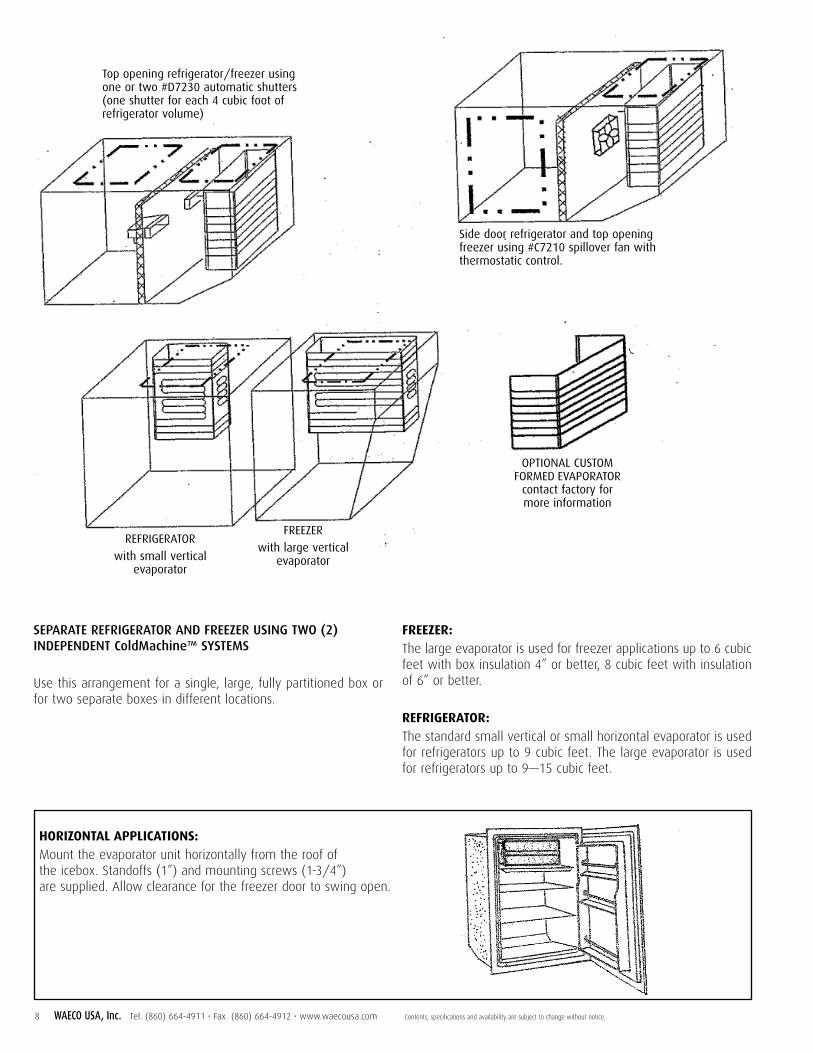
Top opening refrigerator/freezer usingone or two #D7230 automatic shutters(one shutter for each 4 cubic foot ofrefrigerator volume)
SEPARATE REFRIGERATOR AND FREEZER USING TWO (2)INDEPENDENT ColdMachine™ SYSTEMS
Use this arrangement for a single, large, fully partitioned box orfor two separate boxes in different locations.
FREEZER:The large evaporator is used for freezer applications up to 6 cubicfeet with box insulation 4” or better, 8 cubic feet with insulationof 6” or better.
REFRIGERATOR:The standard small vertical or small horizontal evaporator is usedfor refrigerators up to 9 cubic feet. The large evaporator is usedfor refrigerators up to 9—15 cubic feet.
Side door refrigerator and top openingfreezer using #C7210 spillover fan withthermostatic control.
REFRIGERATOR
with small vertical evaporator
FREEZER
with large vertical evaporator
OPTIONAL CUSTOMFORMED EVAPORATOR
contact factory formore information
HORIZONTAL APPLICATIONS:Mount the evaporator unit horizontally from the roof of the icebox. Standoffs (1”) and mounting screws (1-3/4”) are supplied. Allow clearance for the freezer door to swing open.

Contents, specifications and availability are subject to change without notice. Tel. (860) 664-4911 • Fax. (860) 664-4912 • www.waecousa.com WAECO USA, Inc. 9
MOUNTING THE EVAPORATOR
Plan the installation to allow for minimum modification ofexisting shelving.
1. Using the paper template supplied, mark the location of thefour mounting holes.
2. Position the refrigerant tube exit hole in the icebox forminimum bending and strain on the evaporator and tube set.Mark its location (1-1/2” diameter).
3. Drill the mounting holes using a 9/64” drill and the tube setexit hole using a 1-1/2” hole saw.
4. Unroll the entire tube set. An assistant is very helpful here.It is often easier to unroll the entire tube set and stretch itoutside the boat. Feed the tube set and couplings throughthe holes in the icebox and bulkheads while an assistantsupports the freezer unit and keeps the tubing feedingsmoothly without damaging it. Be careful not to kink,flatten or strain joints. Make sure the plastic caps are inplace over the refrigerant couplings. Keep dirt out of thecouplings.
5. Feed the tube set through the boat to the compressor unit.Do not attempt to connect the mating couplings or removethe plastic caps yet.
6. Fasten the freezer unit to the icebox liner with 1-3/4”stainless steel screws and 1” plastic standoffs supplied.
7. Position the rubber insulation sleeve on the tube set so thatits end is flush with the inside of the liner of the icebox withthe balance extending outside.
8. Form excess tubing, if any, into an 18” (approx) diameter coil in the horizontal plane above the compressor unit or at any other convenient location.
9. As shown below, seal the icebox hole using the masticsealant (“Mortite”) supplied.
OUTSIDE OF BOX
SEALING HOLEIN ICEBOX
REFRIGERANTCOUPLINGS
INSIDE OF BOX
InsulationInside of Icebox
Mastic Sealant
Tubing
Fill space with scrap Insulation
Male Couplings Female Couplings
Rubber sleeve

ALL-METAL PIERCING TYPE COUPLINGS
Once connected, the All-Metal Piercing Type Couplings on thissystem cannot be disconnected without total loss of therefrigerant charge.
DESIGN ADVANTAGES: NO LEAKS: Couplings cannot leak prior to connection becauseboth halves are sealed shut by brazed all-metal diaphragms.
MIX & MATCH: Each half of your system is precisely charged withrefrigerant at the factory. After coupling together, the completedsystem will have the correct total charge.
RESULT: Any Adler/Barbour VD-150 series aluminum evaporator,VD-160 PowerPlate, or VD-170 series blower evaporator can beconnected to any CU-100 ColdMachine™ or CU-200SuperColdMachine™ condensing unit.
NOTE: Our 50 Series and 80 Series products each have their own“families” of charge-balanced evaporators. They are notinterchangeable with each other or with the ColdMachine™evaporator family. Nor can a 50 Series or 80 Series condensingunit be used to replace a ColdMachine™ CU-100 or CU-200condensing unit by coupling it to a ColdMachine™ Series VD-150,VD-160, VD-170 evaporator.
TOOLS FOR THE ALL-METAL PIERCING TYPE COUPLINGS:• Use a 5/8” wrench for the male coupling
• Use a 13/16” wrench for the female coupling
• Tighten both couplings to 12–14 ft / lbs. (16.3 to 19.1 newton/meters)
TOOLS FOR THE TUBE SET CONNECTION TO POWERPLATE:• Use a 5/8” wrench for the male coupling. Do not loosen the
coupling from its brazed-on base.
• Use a 3/4” wrench for the female coupling. Do not loosen thecoupling from its brazed-on base.
• Tighten both couplings to 12–15 ft / lbs. (16.3 to 20.3 newton/meters)
BEFORE CONNECTINGSecure tubing and wiring to protect from chafe and vibration.• Coil the excess tubing and the thermostat wiring
harness in an 18” to 24” diameter coil and secure preferably in a horizontal orientation.
• Support the refrigerant tube set and the wire harness usingclamps and/or plastic wire ties (4 supplied).
• Keep the tube set and harness out of bilge water and protectedfrom chafe and vibration.
• The tubing must not be allowed to vibrate or chafe.
• Seal the exit hole in the icebox wall using the suppliedmastic.
ALL-METAL PIERCING TYPE REFRIGERANTCOUPLINGS AS USED ONADLER/BARBOUR SYSTEMS COMMENCINGJANUARY 2001
DESIGN & OPERATIONA complete 5780 series coupling consists of the combination ofmale and female coupling halves. You have the option ofchoosing either coupling half with or without a charging port,depending on your particular application.
COUPLING HALVES BEFORE CONNECTIONDiaphragms in the coupling halves provide a seal that preventsrefrigerant loss before connection. The male half (right unit)contains a cutter blade, the metal refrigerant sealing diaphragmand intermediate synthetic rubber seal which prevents loss ofrefrigerant while the coupling is being connected. The female half(left unit) contains a metal diaphragm, which is leakproof metalclosure.
COUPLING HALVES CONNECTEDTightening the union nut draws the coupling halves together,piercing and folding both metal diaphragms back and openingthe fluid passages, thereby providing minimal restriction to flow.When fully coupled, a parent metal seal forms a permanentleakproof joint between the two coupling halves preventing theloss of refrigerant to the atmosphere.
Diaphragms Cutter
Parent Metal Seal Intermediate Seal
COUPLING HALVES BEFORE CONNECTION
COUPLING HALVES CONNECTED
10 WAECO USA, Inc. Tel. (860) 664-4911 • Fax. (860) 664-4912 • www.waecousa.com Contents, specifications and availability are subject to change without notice.

Contents, specifications and availability are subject to change without notice. Tel. (860) 664-4911 • Fax. (860) 664-4912 • www.waecousa.com WAECO USA, Inc. 11
The three illustrations below show you a cutaway viewof the male and female coupling halves being joined at20%, 50% and 100% connection.
NOTE the way the cutter blades pierce the diaphragmsand fold them back out of the flow path. Also note thedifference in the final sealing area before and aftertorquing.
20% Connected 50% Connected
Final Sealing Areaconnected aftertorquing
Final Sealing Areaconnected prior totorquing
100% Connected

12 WAECO USA, Inc. Tel. (860) 664-4911 • Fax. (860) 664-4912 • www.waecousa.com Contents, specifications and availability are subject to change without notice.
STEP-BY-STEP: ASSEMBLING THE ONESHOT COUPLINGS
COUPLINGS MUST BE IMMACULATELY CLEAN— Leaving plastic caps and plugs in place, carefully wipe off
the fittings to remove dirt, dust and moisture. Now remove theplastic caps from the refrigerant couplings on the compressorunit, and from the mating refrigerant couplings at the end ofthe tube set. Don’t touch the brass hex dome nuts on theside ports of the evaporator couplings! They are there forpossible future servicing only.
CONNECT THE LOWER REFRIGERANT COUPLING FIRST— Thread the coupling halves together by hand to ensure proper
mating of the threads. When screwing the male and femalehalves together, align them carefully to avoid strain and crossthreading. If you have difficulty aligning the coupling halvesproperly, it may be necessary to temporarily shift thecompressor unit for better alignment.
TURN ONLY THE FREE-TURNING PART OF THE FEMALE COUPLING— Do not try to turn the male coupling. Just hold it with your 5/8”
wrench. If the male coupling is twisted from its copper tubing,there will be a refrigerant leak (that is why 2 wrenches mustbe used).
— Using the 5/8” wrench on the male coupling body hex and the13/16” wrench on the female coupling (holding the malecoupling hex stationary), tighten (CW/Clockwise) the femaleuntil the coupling halves bottom out and strong resistance isfelt. THIS WILL REQUIRE ABOUT 6 FULL TURNS.
— Work rapidly to minimize any possible escape of refrigerantpast the temporary rubber O-ring seal (it is inside the malecoupling). Occasionally there may be a slight “hiss” and/or adrop or two of refrigerant oil when making these connections.Don’t stop if this happens—just continue until the couplingsfeel very tight. The final seal is metal-to-metal).
FINAL TIGHTENING— This step must be performed correctly or a permanent
leak-proof joint will not be achieved. — Using a marker pen, draw a line from the male coupling body
to and over the female coupling as a reference. Tighten thefemale coupling one more 1/4 turn while holding the malecoupling hex stationary. This 1/4 turn is essential to ensurethat the final metal-to-metal seal is completed, forming apermanently leak-proof joint.
FINAL TORQUECoupling Torque required: 12 to 14 foot pounds (16.3 to 19.1newton / meters). Imagine a 14 pound weight at the end of aone-foot wrench) EXCEPT for the small PowerPlate-to-tube setcouplings which require 10–15 ft lbs. See the PowerPlate sectionin your manual.
If your final 1/4 turn did not require this much torque, yourcouplings are still loose. TO REPEAT: The 1/4 turn starts afterthe couplings are already very tight.
Now connect the upper set of couplings.— Same procedure except: the male coupling is held securely by
its support bracket, so you do not have to use 2 wrenches.
— Save the plastic caps in the event the unit ever needs to beuninstalled and returned for service.

Contents, specifications and availability are subject to change without notice. Tel. (860) 664-4911 • Fax. (860) 664-4912 • www.waecousa.com WAECO USA, Inc. 13
INSTALLING THE ANALOG (KNOB TYPE) THERMOSTATMount the thermostatic control unit high in the icebox, away frommoisture and spillage. It should also be visible and accessible. Itis acceptable to mount the thermostatic control unit outside ofthe icebox space if you prefer. At least 12” of capillary sensingtube must be inside the box.
The capillary sensing tube is 36” long and must reach from thethermostatic control unit to the clamping plate on the side of thefreezer unit. It must be routed along the icebox wall—clear offood, shelving, etc.
The thermostat can be mounted by using either the adhesivebacking on the thermostat mounting flanges or the stainless steelmounting screws (supplied).
If using the adhesive backing, the mounting area must be cleanand dry. Peel off the protective backing from the adhesive foamon both mounting flanges of the thermostatic control unit,position carefully and press firmly to adhere.
We recommend that you also use the mounting screws by drillingtwo 9/64” holes through the thermostat flange holes.
INSTALLATION PROCEDURE (see drawing below).
1. Carefully unroll just enough capillary tubing to reach themetal and plastic clamp plates on the side of the freezer unit.Via this tube, the thermostatic control unit “senses” thetemperature of the freezer unit. Bend the last 2 inches backinto a “J” shape. Slide the “J” shaped end between the metaland plastic plates and fasten the screws firmly. Be sure thatfour inches of tubing are clamped under the metal plate orthe thermostatic control unit will not function properly.
2. Secure the coil and tube against chafing. (Leave the excesscapillary tubing coiled). The tube must not touch the freezerunit at any point except the clamp plates or an erratic controlcycle will result.
3. Uncoil the 21 foot electrical harness from the thermostat andrun it alongside the refrigerant tube set to the condensingunit phone jack. Plug this harness into its mating receptacleon the face of the junction box.
VertiCube™ Ice Cube Trays
Thermostatic Control
Plastic Plate
Metal Plate
FORMING & ATTACHING THE THERMOSTATSENSING TUBE TO THE EVAPORATORThe sensing tube from the thermostat mustbe formed into a 2-1/2” “J” and clampedbetween the plastic plate and metal plate
Evaporator
USING THEICE TRAY SEPARATOR
The separator keeps the icecube trays in firm contact with
the cold evaporator.

14 WAECO USA, Inc. Tel. (860) 664-4911 • Fax. (860) 664-4912 • www.waecousa.com
INSTALLING THE DIGITAL THERMOSTAT (if supplied)
This optional control has several advanced features, including:• Touch-pad status indicator for cut-out,
cut-in temperatures• LED relay status indicator• Temperature setpoint display• Programmable setpoint and differential• Large (.56”) red LED display
Installing this control is fast and simple. When plan-ning the control location, keep in mind that the sens-ing bulb wire is 10 feet long.
MOUNTING THE CONTROL HEAD1. Make the cutout for the control 3.1” x 1.35”
(79mm x 34mm)
2. Snap the control head through the mount faceplate.
3. Mount the faceplate using the four black screws provided.
MOUNTING THE TEMPERATURE SENSINGBULB1. Run the sensing bulb and wire into the refrigerated
box to be controlled. Mount the sensing bulb on abox side wall midway between top and bottom,using the two nylon clamps and screws provided.(NOTE: This is an air-sensing bulb, and is notclamped to the evaporator.)
2. Keep the bulb as far away as possible from the evaporator (approximately 2 feet away) and out of the direct airflow if a spillover fan kit isinstalled.
3. Secure the excess wire to protect it from chafe anddamage.
CONNECT THE CONTROL HEAD TO THE CONDENSING UNIT1. The digital control has a pre-wired power and
signal cable, terminating in a male 4-pin phoneplug. This plug mates with the phone jack (socket)located on the face of the electrical box on thecondensing unit and marked “T” STAT CONNECTION.
Cut OutDimensions
3.1”
1.35”
Evaporator
Wall oppositeevaporator unit
Contents, specifications and availability are subject to change without notice. Tel. (860) 664-4911 • Fax. (860) 664-4912 • www.waecousa.com WAECO USA, Inc. 15
MOUNTING THE POWERPLATE
1. Plan the installation to position the PowerPlate in thepreferred orientation: on a vertical wall of the refriger-ator (or freezer) cabinet with the label on top. In thisposition, the PowerPlate will perform at maximumefficiency. If this is not possible, it may be installed inany spatial orientation; but a small reduction of efficiency may result.
2. Position the PowerPlate high in the compartment—within 2 inches of the top for best results.
3. Be sure to leave room for mating and tightening thecouplings that connect the PowerPlate to the tube set.
4. Mark and drill four (4) mounting holes using a 9/64”drill and a tube exit hole using a 1-1/2” hole saw.
5. Be sure to use the supplied four (4) plastic spacers toensure that the PowerPlate is spaced away from thecabinet wall to permit air circulation behind it for bestefficiency. Do not mount the PowerPlate flush againstthe wall as a major loss of performance will result.
POWER PLATE TUBE SET
Drill a 1-1/2” diameter hole through the cabinet wall forthe tube set. Unroll the tube set. Feed the end with thecouplings into the box. Do not remove the protective capsyet.
Position the insulating sleeving OUTSIDE (not inside) therefrigerated space. The end of the sleeve should buttagainst the outside wall of the box (you will be sealingthis joint later with mastic putty included in your kit.)
Route the service port coupling ends of the tube setthrough the boat to the condensing unit. Do not removethe protective caps yet.
Before you connect the refrigerant couplings to thepower plate, refer back to the section entitled“Refrigerant Couplings” for additional information. Havethe required 5/8 and 3/4 wrenches at hand now. Do notallow any dirt, sawdust, foam insulation dust, etc., to getinto couplings ends as this will seriously damage the system.
These couplings are different from the couplings that jointhe tube set to the condensing unit. The small couplingsare screwed, o-ringed, and LocTite-sealed to the basesthat are in-turn soldered to the copper tubes. Therefore,it is most important that you do not unscrew the smallcouplings from their bases. Put your wrenches on thecoupling bodies only!
SMALL COUPLING TORQUE REQUIRED
12–15 foot pounds (less than the large couplings)
CONNECTING THE PLATE COUPLINGS (from tube set toPowerPlate)
1. Remove the protective caps of one mating pair of thecouplings inside the box (start with either pair). Screw thecouplings halves together until they bottom metal-to-metalwith very firm pressure (about 4 turns) using two wrenches:5/8” and 3/4”.
2. Mark the coupling halves. Using your two wrenches (do notuse pliers, visegrips, etc) tighten couplings an additional oneflat (1/6 turn). This should require considerable wrenchtorque. If it did not, you did not “bottom” the couplings first.
3. Repeat the above for the other pair of coupling halves.
IMPORTANT: Save all coupling protective caps. Put them in amarked container and keep aboard. If a future service procedurerequires that any coupling pair be disconnected, these caps mustbe re-installed immediately to keep out dirt.
To connect the couplings to condensing unit, please refer tosection entitled “Refrigerant Couplings.” After completing thissection, seal the black rubber insulating sleeve to the outside ofthe refrigerated box airtight, using Mortite or other (removable-type) caulking sealant. All three (3) feet of sleeve must beoutside the box. This sleeve may butt against the outer wall orthe inner liner.
Excess tubing: Form a coil about 18” in diameter, (taking care notto deform the tubes) in the horizontal orientation if possible, andsecure tightly to the bulkheads, etc. using plastic wire straps.Protect tubing from chafe and vibration with soft sleeving asnecessary.

16 WAECO USA, Inc. Tel. (860) 664-4911 • Fax. (860) 664-4912 • www.waecousa.com Contents, specifications and availability are subject to change without notice.
ELECTRICAL CONSIDERATIONS
WATER COOLED OPTION PACKAGE: How it works and why
To get absolutely top performance from yourSuperColdMachine, you can add this package at any timein the future if not with your original installation. If inletair temperature to the SuperColdMachine exceeds 90°F,switching to water cool mode will produce shorter “on”times and lower average amp draw. As air temperatureincreases, the water-cooled advantage increases. In tropical conditions, the total daily power consumption canbe reduced by 25—40%.
When you select “water pump on” using the switch panelprovided with this option, note that the built-in fan (andthe Powerduct fan, if fitted) continues to run. This ensuresa flow of air over the compressor to keep it relatively cooland is normal.
It is strongly recommended that you switch the pump offwhile using dockside power. With the battery chargerworking, it is more important to extend the life of thewater pump than it is to save battery power.
Example: You left the boat on Sunday night, plugged in,freezer full of food, and left the water pump on. OnWednesday, a plastic bag gets sucked into the pumpintake. The pump runs dry, its impeller shaft locks up, thepump motor stalls. The result is a damaged pump bear-ing requiring replacement (available from WAECO USA).The “pump / fan” fuse may or may not blow. If it does,the frozen food may be lost because the unit may shutdown to protect itself. It is important to shut off the pumpwhen you leave.

Contents, specifications and availability are subject to change without notice. Tel. (860) 664-4911 • Fax. (860) 664-4912 • www.waecousa.com WAECO USA, Inc. 17
Preferred Arrangement
UNacceptable Alignment
Acceptable Arrangement
Overboard DischargeCompressor
Water Line Water LineContinuousRise
Vented Line
CockpitDrain
Air Lock
Discharge
Inlet
Base Vertical Discharge Points UP
Base Horizontal Discharge is approx. Horizontal
WATER COOLED OPTION INSTALLATIONPlease refer to the diagrams below.
Basic rules for a good installation.
1. The pump must be at least 1 foot below waterline at alltimes (regardless of which tack you are on).
2. The pump orientation must be as pictured—no other positions will work.
3. The strainer should be mounted with the bowl pointingdownward, otherwise, it will trap air and possibly airlock the water pump.
4. Inlet thruhull must not be “shared” with any power-drivenpump and absolutely not the engine’s intake! you may“tee-off” a toilet inlet, cockpit drain, galley seawater foot-pump line, etc., provided that the seacock is at least 2”below the waterline.
5. Inlet thruhull must have a “scoop” facing forward on theoutside of the hull to prevent “back siphoning.” At highsailing speeds, the flow direction may reverse, introducingair into the pump and damaging it. Failure to provide thisscoop is the major cause of pump failures.
6. Heeling can obviously be a problem since the pump may bewell below the waterline at rest or on one tack, but not onthe other. Traps and airlocks may also be created when theboat is heeling. In most cases, the positive “ram effect”created by the outside hull inlet scoop will overcome theseproblems. This is another reason why the scoop is soimportant.
7. Overboard thruhull (supplied) must be above the waterline—so you can verify pump operation.
8. Total hose length must not exceed the 15 feet furnished.
9. Total lift (example: highest point of piping above pump)must no exceed 5 feet.
10. No “traps” allowed! This means no “dips” in hoses. Theymust run level or steadily uphill from inlet to strainer topump to highest point. To simplify, if you picked the boat upin slings, the entire water circuit (except for strainercontents) must drain through the inlet thruhull.
NO OTHERPOSITIONS ARE
PERMITTED!
18 WAECO USA, Inc. Tel. (860) 664-4911 • Fax. (860) 664-4912 • www.waecousa.com Contents, specifications and availability are subject to change without notice.
BATTERY RECOMMENDATIONS
A minimum of THREE marine-grade batteries are stronglyrecommended: One exclusively for engine starting and the othertwo as a single bank for all other DC electrical devices such aslights, electronics and your system. The second battery or groupof batteries (wired in series or parallel depending on voltage) iscommonly called the “house bank.” A standard marine batteryselector switch should be installed to isolate each battery orbattery bank.
The house bank should be at least 300 amp/hour capacity. Moreis desirable. The larger the battery bank, the longer you canoperate the various loads between engine charging and thefaster you can recharge. This is because the alternator actualoutput in amps is greater into a larger battery bank. Expertssuggest the bank’s nominal amp/hour rating should be fourtimes (4x) the alternator’s rated (hot) output.
The following ampere/hour capabilities are recommended forthe house bank, which serves the ColdMachine™.
For the “casual cruiser” 25-35 feet, seldom away from dockfor longer than overnight …minimum 200 amp/hours
For the “serious cruiser” 30-50 feet, often cruising for a weekor more …minimum 300 amp/hours
For the charter yacht or tropics-based “serious cruiser”operating in hot climates and requiring greater quantities ofice cubes and frozen foods …. Minimum 400 amp/hours.
High Output Alternator, Electrical Management Systems, andBatteries
The continuing proliferation of electrical and electronic devicesaboard boats has produced great interest in reducing engine-running time required for battery charging. Specialty high-outputalternators are readily available. Several manufacturers offercomplete electrical generation and management systems. It isnow entirely practical for medium sized cruising boats to supportDC refrigeration, inverter-driven galley appliances, navigationalsystems including computerized charting and radars, all with veryacceptable daily engine hours for battery charging.
As to batteries, a good deal of misinformation still existsregarding “marine,” “deep-cycle” and “deep-discharge” batteries.These terms generally describe a battery constructed to providesmall-to-moderate currents for long periods of time, as opposedto short bursts of high current to start engines. While “deep-cycle” batteries start engines quite satisfactorily, engine-startingbatteries are very poor for small current, long-term tasks.Automotive, sealed, or so-called “maintenance-free” wet-typebatteries are okay for the engine start battery, but are not suitablefor the house or service battery bank that runs all the otherequipment on your boat regardless of how they are labeled. A
few manufacturers of genuine, marine, heavy-duty, deep cyclewet-type batteries are creating a public awareness of theinadequacies of disguised, re-labeled automotive batteries formarine use, particularly as house batteries in sailing yachts.
GEL and AGM Batteries (as distinguished from so-called“maintenance free” auto batteries ): Several high quality productsare available in all popular sizes. They perform comparably to thevery best wet-type deep cycle traditional batteries, but requirelittle or no maintenance. However they require very carefullyregulated charging systems, and cannot be simply interchangedwith wet batteries.
What all this means is that a boat owner with a full complementof equipment aboard such as electronics, refrigeration, auto-pilot,stereo, etc and who feels the engine must be run too long forbattery charging, can get very substantial improvements by usingthe technology and equipment now available.
We strongly urge all boat owners to take advantage of theexcellent technical manuals, articles and products now availablein the marine industry. There is no longer any reason to put upwith long hours of engine running and marginal electricalsystems.
WIRING THE SYSTEMAll Adler/Barbour products from December 1998 forwardincorporate a new, more powerful and more energy efficient compressor featuring a 3-phase AC motor, which is driven anddigitally managed by the electronic module (the finned deviceon the side of the compressor).
NOTE: The electronic module is not repairable, should not beopened and must be replaced if damaged.
This control unit, like most electrical devices, requires fairly“clean” DC current for stable operation and long service life.Batteries provide clean, ripple-free DC current. Many batterychargers, alternators and AC/DC converters may not. This meansthat the ColdMachine should not be connected directly to any ofthese devices, unless a battery is between them in the circuit.

Contents, specifications and availability are subject to change without notice. Tel. (860) 664-4911 • Fax. (860) 664-4912 • www.waecousa.com WAECO USA, Inc. 19
VOLTAGE DROPSWhen in the starting mode, the ColdMachine may momentarilydraw nearly 10 amps, even though the continuous runningcurrent is between 3 and 5 amps. If the electronic control moduledoes not “see” at least 11.0V DC during the start period, it willabort. Therefore, to avoid erratic problems, the supply wiringmust be correctly sized-please see Wire Size Table.
Make your wiring connection in one of these three ways:1. Directly to the battery via a 15A breaker
(recommended). (*) See note.
2. To a heavy output terminal on the battery selector switch,via a 15A breaker (recommended).
3. To the ship’s distribution breaker panel. This method isacceptable if the selected breaker is directly re-wired tothe main battery selector switch with its own heavy wire.If not directly re-wired, the voltage drops within the panelwill be excessive and cause erratic operation.
Use the shortest possible route for wiring between the unit andbattery to avoid voltage drops.
Install a 15 amp circuit breaker in the positive leg for lineprotection. The circuit breaker is also necessary for long “off”periods because even with the thermostat off, there is still a milli-amp range current flow in the system.
Make sure that all wiring conforms to applicable safetyregulations. Note that a replaceable 15 amp fuse located on thecondensing unit provides backup protection in case the breakershould fail in the shorted condition.
Use marine quality connectors and circuit breaker to preventvoltage drops in the supply circuit to the ColdMachine. Also, donot install voltage dropping devices such as indicator lights, voltand amp meters, etc., in the 12 volt DC wiring circuit.
Correct polarity is critical. If you connect in reverse, the systemwill not operate. Should this occur, correct your wiring. Thesystem will automatically re-start.
(*) NOTE: The main fuse on the CM or SCM junction box is 15amp. WAECO calls for a 15 amp breaker in the (+) DC supply for several reasons:
1. The breaker will generally trip before the fuse will blow,thus saving a crawl through the bilge.
2. The installer may use an incorrect higher-rated breaker, sothe 15A fuse will still provide proper circuit protection.
3. In very hot ambient temperatures, the largest systems maybriefly draw more than 10 amps for a few seconds,resulting in nuisance trips if a 10A breaker is fitted.
MAKING THE POWER CONNECTIONSUse color-coded wire so you know which is positive (+) andwhich is negative (-). Connect the positive wire to the (+) screwon the terminal strip. Contact the (-) terminal screw to thenegative lead to the battery, or the main negative terminal orbusbar.
WIRE SIZEWire size is critical. If you use undersized wire, your system willrun erratically, often fail to start, produce unsatisfactory coolingand fail early in its service life. Use a wire gauge size based onthe total distance from the compressor unit to the battery selectorswitch.
WIRE SIZE TABLE
Maximum distance from Gaugecompressor unit to battery AWG
4’ and under #14
5’ to 10’ #12
11’ to 17’ #10
18’ to 27’ #8*
28’ to 35’ #6*
36’ to 50’ #4*
*The terminal block on the junction box will accept #10 AWG wiremaximum. If you need to run heavier wiring, you shouldterminate it at a suitable-sized heavy terminal strip and run #10AWG from there to your condensing unit.

20 WAECO USA, Inc. Tel. (860) 664-4911 • Fax. (860) 664-4912 • www.waecousa.com Contents, specifications and availability are subject to change without notice.

Contents, specifications and availability are subject to change without notice. Tel. (860) 664-4911 • Fax. (860) 664-4912 • www.waecousa.com WAECO USA, Inc. 21

22 WAECO USA, Inc. Tel. (860) 664-4911 • Fax. (860) 664-4912 • www.waecousa.com Contents, specifications and availability are subject to change without notice.

Contents, specifications and availability are subject to change without notice. Tel. (860) 664-4911 • Fax. (860) 664-4912 • www.waecousa.com WAECO USA, Inc. 23

24 WAECO USA, Inc. Tel. (860) 664-4911 • Fax. (860) 664-4912 • www.waecousa.com Contents, specifications and availability are subject to change without notice.
OPERATION OF SYSTEM
START UPTurn the thermostatic control clockwise to about #2 or #3, (#1 on thethermostatic control is the warmest setting.....#7 is the coldest)
The ColdMachine system will now start. Within a few minutes, theevaporator will begin to frost (note that a PowerPlate will take muchlonger before frost is visible on the surface). The system will operatecontinuously until the box cabinet and contents have been brought to theselected temperature. The system will then cycle off, and thereafter cycleon and off—maintaining proper temperature (similar to a homerefrigerator).
AC/DC OPERATIONThe ColdMachine will also operate automatically at dockside with theaddition of a battery charger. We recommend a quality MARINE batterycharger (not an automotive charger) of sufficient size to handle yourColdMachine along with the other onboard DC loads (such as lights,stereo and electronics).
For the ColdMachine, figure approximately 5 amps when running. Theaverage draw, as the ColdMachine cycles on and off, is 1.8 to 2.4 ampsfor most 4 to 8 cubic foot iceboxes with average (3 inch plus) rigidpolyurethane foam insulation.
MAINTENANCERegular or seasonal maintenance is normally not needed, nor ismaintenance required for winter storage or decommissioning. However,you should wash the evaporator occasionally and again before winterstorage (use a mild detergent such as Joy or Ivory). In addition, the aircondenser (the radiator-like object in the condensing unit) can getclogged with dirt and should be carefully vacuumed seasonally with asoft brush attachment. Be careful not to bend the cooling fins. If a water-cooled option kit is installed, the water circuit must be drained or filledwith anti-freeze solution.
DEFROSTINGDefrost your refrigerator when frost gets over 1/4” thick. This should notoccur in less than a month or so. Excessively fast or thick frost formationis an indication of moist, outside air entering through a poorly-sealed lid,doors or liner joints. These conditions must be eliminated for properperformance.
The best way to defrost is to turn the power off. Open the icebox lid ordoor and allow sufficient time for the freezer unit to defrost naturally.Never use an icepick, knife or other metal object—you could pierce therefrigerant coils.
BATTERY CAREBatteries are one of the most neglected and abused items on boats.Unlike automobiles, boat engines run slowly and infrequently. Thebatteries tend to be buried in the bilge, are damp, dirty and chronicallyundercharged. Boat wiring is subject to corrosion at various connections,which creates voltage drops as we add more electrical devices eachseason. As these electrical loads grow, it becomes even more importantthat you keep your battery and charging system at top efficiency.
In addition, batteries can be deceptive. They may look good and readnormal voltage, but may have deteriorated internally and be unable todeliver adequate power for more than short periods of time.
WET TYPE BATTERIESCheck you batteries at least every month with a hydrometer(inexpensive and available from automotive supply stores). The readingsof each cell should be approximately the same. If one reading is lowerthan the other, it indicates a defective battery. Use distilled water only.
EQUALIZING (WET TYPE BATTERIES ONLY)During periodic equalizing, the battery voltage can exceed 15 or even 16volts. To prevent possible damage to your unit, shut theAdler/Barbour system off before starting the equalizingprocess.
ALL BATTERIESCheck your batteries seasonally with a “battery load tester” (obtain froma boatyard or mechanic). This tests the battery’s condition and capacityunder a heavy actual load.
If your batteries do not pass these test, replace them. You are justwasting valuable fuel, engine hours and time in trying to charge them.Observing the following points can add to the dependability andoperational life of your battery:
• Keep the tops of the batteries clean and dry. A damp battery can lose20% of its charge in a day.
• Keep the battery post clamps tight, clean and free from corrosion.

Contents, specifications and availability are subject to change without notice. Tel. (860) 664-4911 • Fax. (860) 664-4912 • www.waecousa.com WAECO USA, Inc. 25
WINTER OPERATIONIf ambient temperatures drop below 35°F in the operational area of thecondensing unit, it may be necessary to block off half of the aircondenser face area (on the side opposite the condenser fan motor) witha piece of cardboard to maintain system efficiency. The cardboard cansimply be taped in place for the winter season and removed in the springwhen seasonal temperatures return to above 35°F.
PROGRAMMING DIGITAL CONTROL(if supplied with your system)
The digital thermostat is pre-programmed at the factory. If settings haveto be changed, the following information will allow you to easilyprogram the controller.
• SET POINT (SP) This is the desired temperature of the refrigerator. Itis pre-programmed at the factory to a temperature range of 35—45°F(0—20°F for freezer).
TO PROGRAM SET POINT (SP1)1. To start the programming sequence, press the SET button once. Unit
displays “SP1” (set point 1)
2. Press the SET button again to display SP1 value.
3. To program an increase or decrease in SP1, press the appropriateADJUST arrow.
4. To complete the programming sequence, press the SET button untilthe screen goes blank. After five seconds, the unit will automaticallydisplay sensor temperature.
• DIFFERENTIAL (dF) This is the difference between the cut-in and cut-out temperature of the thermostat. The differential must be a negativevalue. If it is set as a positive value, the relay in the thermostat willclose on temperature fall and open on temperature rise. In otherwords, it will respond as a heating thermostat instead of a coolingthermostat. Do not set a positive differential. Do not set a differentialof 0 (zero).
• HIGH & LOW SET POINT LIMITS (HI & LO) Allow you to limit therange at which temperature set points can be programmed. This isfactory set and should not need to be adjusted, unless changing fromrefrigerator to freezer or vice versa..
TO PROGRAM DIFFERENTIAL (dF) (HI) AND (LO) POINTSShould only be adjusted if necessary. To start the process, you mustpress the hidden button located behind the “F” symbol at the upper rightcorner of the control to program these settings. After programming, youmust press the “F” button until the screen goes blank.
1. Press “F” once. “DF1” will appear on the screen. Press “F” again. Anegative value will appear. Use the appropriate “ADJUST” arrow tochange this setting.
2. This event must be set to a negative value but should not be lowerthan —5 to avoid short-cycling.
3. Press the “F” button again. The screen will read “HI”. Press “F” againand you will read a value. This is the high setpoint limit. It preventsthe control from being tampered with and raised any higher than thispoint. Now you can press the “ADJUST” arrows to get to your desiredsetpoint.
4. Press the “F” button again. The screen will display “LO”. Press the “F”and you will read the LO setpoint limit. Use the “ADJUST” arrows tochange it.
5. Pressing the “F” button again will display “CAL”. Press “F” again andyou should see 00. This should never be changed. If “CAL” reads anyvalue either than 00, use the “ADJUST” arrows until it reads 00.
6. Press the “F” button again. You will see a blank screen. Thereprogramming has been accepted and the control will now revert tothe box temperature display mode.
NOTE: If the programming sequence is interrupted for more than 15seconds or not set to the blank screen, the thermostat will revert totemperature display without acknowledging any new inputs.
• CALIBRATION (CAL) Factory calibrated to a certified standard.
Do not alter or change.

26 WAECO USA, Inc. Tel. (860) 664-4911 • Fax. (860) 664-4912 • www.waecousa.com Contents, specifications and availability are subject to change without notice.
ELECTRONIC MODULE SYSTEM MANAGEMENT AND PROTECTION
The ColdMachine is designed for nominal 12 volt DC operating. Thenormal operating range is 10.0 volts —15.0 volts. The electronic modulewill automatically shut off the system if voltage at the module inputterminal falls below 10.0 volts. As the battery recharges, the electronicmodule will automatically turn the system on when the voltage reaches11.1 volts. This circuity protects the battery from the damaging effects ofa complete discharge and also protects the ColdMachine from chroniclow voltage operation.
MANAGEMENT FUNCTIONS INCLUDE:• High and low voltage protection (10.0 V DC to 17.0 V DC ) (*) NOTE
• Reverse polarity protections (compressor will not operate)
• High temperature cutout if electronic unit is overheated
• Overload protection if compressor is dangerously overloaded (byovercharging or extreme high temperature)
• Automatic start abort if the compressor motor cannot rotate
• Battery protection: Low voltage cut out prevents total battery dischargeor drain
• Fan relay circuit protection (0.5 amp max; overcurrent will causesystem to shut down)
• LED diagnostics
(*) NOTE: If voltage reaches 17.0 V DC, the module “thinks” it is a 24 VDC system suffering from low voltage, and LED will display one flash. Themodule will probably survive. The fan(s) and pump (optional) may not.
OPERATIONAL ERRORS INDICATED BY THEFLASHING LED ON THE CONDENSING UNIT
If the electronic module “senses” a malfunction, it will auto-matically switch into its protective mode and will makerepeated start attempts at about 1 minute intervals.
(1) FLASHLow Voltage Supply. If the supply voltage measured at theupper (-) and (+) terminals of the electronic module dropsbelow 10.0 V DC, the system will shut down. It will not restartuntil 11.1 V DC is maintained throughout the momentary high-current start attempt.
(2) FLASHESRelay Coil Circuit Overload. The relay coil and/or its wiring isshorted. The electronic module shuts off the output current thatdrives the coil. The fan(s) and water pump (optional) will notoperate. (*)
(3) FLASHESCompressor Motor Starting Problem. The motor rotor (arma-ture) is mechanically blocked or stuck or the differential pres-sure inside the compressor is too high and the motor cannotstart.
(4) FLASHESUnder-speed Compressor Motor Problem. If the compressorcannot reach or maintain its minimum speed of 1800 RPM (dueto poor condenser air flow, overcharge, air in the system,extremely hot ambient temperature), it will automatically shutdown.
(5) FLASHESElectronic Overload. The electronic module is overheatedand/or the system has been heavily overloaded (by very highambients, fan and/or pump failure, air in the refrigerant circuit,and/or refrigerant overcharge.
If the system displays any unusual symptoms, runs continuous-ly or does not cool properly, please refer to the Trouble shoot-ing guide.
(*) NOTE: Do not operate the system longer than 10 minuteswithout the fan running.
For further assistance, please contact WAECO USA’S
TECHNICAL ASSISTANCE DEPARTMENT Monday through Friday
8am to 5pm ESTTel: (860) 664-4911Fax: (860) 664-4912

Contents, specifications and availability are subject to change without notice. Tel. (860) 664-4911 • Fax. (860) 664-4912 • www.waecousa.com WAECO USA, Inc. 27
LED BLINK SYMPTOM TEST / DIAGNOSIS CORRECTIVECODE ACTION
Compressor and fan do not No power to unit / Blown fuse Replace MAIN fuse (15 amp).attempt to start Correct wiring refer to manual
Reverse polarity Correct polarity
3 Pressure too high Wait, try again
3 Faulty electronic module Replace moduleFaulty compressor Call WAECO USA (860.664-4911)
2 Faulty / shorted delay Replace PCB inside stainlesssteel electrical box
1 Compressor and fan attempt Low voltage at unit: C/o=9.6V Charge batteryto start as shown by momentary C/in=11.0Vvoltage dip, fan movement orcompressor vibration
1 Excessive voltage drop from battery Correct wiring (refer to manual)to unit during start-up attempt
3,4 Internal refrigerant pressures Shut off power, wait 15 minutes,not yet equalized restore power
Faulty electronic module Replace electronic module
3 Faulty compressor Call factory
5 Excessively hot electronic module Improve air flow to unit
4,5 Overheated compressor Improve air flow to unit
2 Compressor does not run, Defective or shorted relay or Replace PCB inside stainless steelfan does not run wiring drawing over 0.5 amps electrical box
activates protective circuit in electronicmodule
Fan / Pump fuse blows Replace fuse (5 amp)
Faulty fan Replace fan
Faulty wiring to fan Repair wiring fault
Fan okay, but module faulty Replace electronic moduletest by putting 12V to fan directly
Intermittent compressor/ Poor electrical supply, chronic Review manual, correct wiring fan operation voltage fluctuations faults, recharge or replace battery
Faulty control module Replace control module
Faulty compressor Call WAECO USA (860.664-4911)
Power duct fan does not run Faulty fan (test with 12V DC power Replace fansource)
Faulty wiring to power duct fan Repair wiring
TROUBLESHOOTING

28 WAECO USA, Inc. Tel. (860) 664-4911 • Fax. (860) 664-4912 • www.waecousa.com Contents, specifications and availability are subject to change without notice.
LED BLINK SYMPTOM TEST / DIAGNOSIS CORRECTIVECODE ACTION
Compressor and fan cycle Digital thermostat control setting Re-program digital control, lower-but box not cold enough too warm or control is defective ing set point (SP) and “HI” and
“LO” settings (see manual) orreplace control
Analog thermostat set too warm Adjust control or replaceor defective
Evaporator too small for box Call WAECO USA (860.664-4911)
Thermostat tube touching evaporator See manual, correct
Compressor and fan runs, Inadequate air flow to condensing Remove blockage and/orevaporator frosts, but box unit improve circulationnot cold enough
Refrigerant undercharge-only part Call WAECO USA (860.664-4911)of the evaporator is frosting*
Refrigerant overcharge-evaporator Call WAECO USA (860.664-4911)is fully frosted plus frost continues along tube set beyond rubberinsulating sleeve
Partial clog in refrigerant circuit Call WAECO USA (860.664-4911)only part of the evaporator isfrosting
3 Box insulation is inadequate or Re-insulate. Contact local dealerbox too large for assistance. Find local dealer
online: www.waecousa.com
3,4,5 Condensing unit in very hot area Relocate unit, remove blockageand/or condenser fins blocked provide better airflow, review
Duct Kit section of this manual
Thermostat tube touching evaporator See manual, correct
Compressor and fan run No refrigerant in system: Loose Call WAECO USA first. Decision tocontinuously, no cooling at all couplings, defective component(s) repair locally or return entire
punctured evaporator, broken system (evaporator & condensingtubing. “Hiss” may be audible unit) to factory will be madeat evaporator when compressor before proceeding.is running
Complete clog inside refrigerant Call WAECO USA for assistancecircuit: no audible “hiss” at in confirming this diagnosis andevaporator while compressor best way to proceedis running
*NOTE: FEDERAL LAW PROHIBITS SERVICING OF THIS REFRIGERANT CIRCUIT BY NON-CERTIFIED OPERATORS.PLEASE CALL WAECO USA’S TECHNICAL SERVICE DEPARTMENT FOR ASSISTANCE.
TROUBLESHOOTING

Contents, specifications and availability are subject to change without notice. Tel. (860) 664-4911 • Fax. (860) 664-4912 • www.waecousa.com WAECO USA, Inc. 29
LED BLINK SYMPTOM TEST / DIAGNOSIS CORRECTIVECODE ACTION
Compressor and fan run Thermostat control set too cold Turn knob (analog) to lowercontinuously, food in refrigerator number, and if digital re-programfreezes
Thermostat shorted, defective or Call WAECO USA (860.664-4911)malfunctioning
Box very small or unusually Install partition betweenwell insulated evaporator and perishable food
section
Thermostat sensing bulb not See manual, correctmounted correctly
Water pump runs, no water flow Air in pump, cannot self-purge Check piping for leaks, air entryre-prime pump, re-pipe(see instructions)
Impeller spindle damaged from Obtain service parts from factorydry running
Obstructions in inlet pipe, strainer, Locate and eliminateor outlet piping
Water pump motor does not run, Blown FAN/PUMP fuse on replace with 5 amp fusedoes not pump condensing unit
Defective wiring Locate and repair
Defective pump replace entire pump
Foreign material jammed pump Disassemble and removeimpeller
TROUBLESHOOTING
30 WAECO USA, Inc. Tel. (860) 664-4911 • Fax. (860) 664-4912 • www.waecousa.com Contents, specifications and availability are subject to change without notice.
PROCEDURE FOR REMOVING COMPRESSOR UNIT1. Turn off DC power supply breaker for unit.
2. Disconnect the mating plugs of the thermostat control wireharness approximately one foot from compressor unit.
3. Remove both DC power supply wires from the upper (-) and(+) screws of the terminal strip module.
4. Shut inlet seacock (if water cool option is installed). Removethe 2 hoses from the condensing unit.
5. Disconnect the mating plugs of the digital or analogthermostat located on the condensing unit.
6. The refrigerant in this system must first be extracted by aqualified technician using approved recovery equipmentbefore the couplings can be loosened or disconnected.
7. Disconnect both refrigerant couplings. Use two open-endwrenches: 13/16” hex or 10” adjustable to turn the femalecoupling. 5/8” hex or 10” adjustable to hold the malecoupling.
8. Turn only the female coupling. Do not turn the male coupling.If you twist the coupling from its soldered tubing connection,you will have a refrigerant leak. This is why you must usetwo wrenches.
9. Remove the compressor unit from the boat. Handle carefully.Do not pick it up by the tubing or electronic module. Becareful not to cut your fingers on the cooling fins and do notbend them (The fins are soft and thin for maximumefficiency).
PROCEDURE FOR REMOVING EVAPORATOR AND TUBE SET1. Turn the thermostatic control to OFF.
2. Disconnect the 12V DC power supply to the compressor unit.Carefully remove the sensing tube of the thermostatic controlfrom its clamp on the side of the freezer by loosening twoscrews and sliding out the “U” bend section of the tube.
3. Disconnect both pairs of refrigerant couplings at thecompressor unit (see item 4 of the “Procedure for RemovingCompressor Unit.”)
4. Remove the soft mastic caulking material from the exit holeinto the icebox where the tubing and wire harness passthrough.
5. Using a “stubby” screwdriver, unscrew the four mountingscrews (save these) and carefully withdraw the entirefreezer and its 15 foot tube set from the icebox.
6. Be careful not to kink or flatten the tubing. Screw the plasticsealing caps into the coupling to keep them clean.
7. Carefully roll up the entire coil by rolling it around acylindrical object of about 18” diameter.
PROCEDURE FOR REMOVING POWERPLATE AND TUBESET1. Defrost the PowerPlate and thoroughly dry the small
couplings.
2. DIsconnect the 12V DC power supply to the condensing unit.
3. Disconnect the couplings at the PowerPlate, using correctwrenches and taking care not to turn the soldered-in bases.
4. Install the plastic caps to protect the coupling.
5. Remove the PowerPlate by extracting the mounting screwsand plastic standoffs.
6. Remove the tubeset, first removing the soft self-sealingmastic at the box exit.
7. Coil the tubeset carefully around a 12” diameter cylindricalobject.

Contents, specifications and availability are subject to change without notice. Tel. (860) 664-4911 • Fax. (860) 664-4912 • www.waecousa.com WAECO USA, Inc. 31
WAECO USA LIMITED WARRANTY
WAECO USA, Inc. warrants its products to be free of defects inmaterials and workmanship for the periods specified below subject to the specified conditions and limitations. What WAECOWill Do: Repair or replace (choice of remedy at Company's discre-tion) goods or parts that prove to be defective in materials orworkmanship after examination by a factory representative orauthorized service dealer.
How long Coverage Lasts: COMPRESSOR PRODUCTS
Labor: WAECO will pay for necessary labor from an authorizedservice agent for one year from date of purchase or third partyinstallation. For OEM factory installed products the duration isone year from the date of purchase of the vehicle (vessel).
Parts: WAECO will pay for necessary parts for two years fromthe date of purchase or third partyinstallation. For OEM factoryinstalled products the duration is two years from the date of purchase of the vehicle (vessel).
What is Not Covered:
1. Damages due to accident, misuse, abuse, normal wear,improper installation, lack of reasonable and necessary main-tenance, transportation, corrosion, tampering, improper repair,unusual physical or electrical stress or recharging of thecoolant.
2. Electric light bulbs or replaceable fuses.
3. Failures due to use of the products in applications for whichthey are not intended.
4. Warranty coverage following unauthorized service.
5. Warranty coverage following transfer of ownership.
How State Law Relates to this Warranty:
This warranty gives you specific legal rights, and you also haveother rights, which vary from State to State.
THERE ARE NO OTHER WARRANTIES OF MERCHANTABILITY, FITNESSFOR PURPOSE OR ANY OTHER KIND. ANY EXPRESSED OR IMPLIEDARE HEREBY DISCLAIMED AND EXCLUDED. THE COMPANY SHALLNOT BE LIABLE FOR CONSEQUENTIAL DAMAGES TO YACHTS, EQUIP-MENT OR OTHER PROPERTY OR PERSONS DUE TO ANY FAILURE OFWAECO USA PRODUCTS. THIS WARRANTY IS EXPRESSLY PROVIDEDIN LIEU OF ALL OTHER WARRANTIES EITHER EXPRESSED OR IMPLIED.
Should your new WAECO USA or ADLER/BARBOUR product notperform properly, please refer to the trouble shooting section
of your owner’s manual first.
If the problem persists, please have the following information available before placing a call to us:
PRODUCT SERIAL NUMBER
DATE OF PURCHASE
LOCATION OF PURCHASE (DEALER)
Call WAECO USA’s Customer Care Department @ (860) 664-4911 Monday – Friday 8:00am to 5:00pm EST.
Please do not return to place of purchase. Call us, it may be something that was simply overlooked
and could easily be resolved over the telephone.
RETURN POLICY
Returned products, parts and assemblies are subject to thefollowing terms and conditions:
1. A Return Merchandise Authorization number (RMA) mustbe issued PRIOR to the item(s) being returned for credit orrepair.
2. RMA’s will be issued prior to the return. When requesting a RMA number, the following information must be furnished:
• Your name or company name, address and telephone number.
• Items (part numbers) being returned.
• Reason for return.
• If possible, supply the WAECO USA order or invoice numberon which the product was shipped.
3. All returns must be sent post paid to:WAECO USA, INCAttention: Service DepartmentRMA#8 Heritage Park RoadClinton, CT 06413
* The RMA number MUST be printed on the exterior carton.
ALL PRODUCTS BEING RETURNED FOR CREDIT ARE SUBJECT TO A 15%RESTOCKING FEE. ALL RMA numbers are valid for 30 days from issuedate.
IMPORTANT INFORMATION

WAECO USA, Inc.P.O. Box #497
8 Heritage Park Road Clinton, CT 06413
Tel. (860) 664-4911 • Fax. (860) 664-4912
www.waecousa.com