installation, operation, and maintenance...installation instructions installation instructions...
TRANSCRIPT
SAFETY WARNINGOnly qualified personnel should install and service the equipment.The installation, starting up, and servicingof heating, ventilating, and air-conditioning equipment can be hazardous and requires specific knowledge andtraining. Improperly installed, adjusted or altered equipment by an unqualified person could result in death orserious injury. When working on the equipment, observe all precautions in the literature and on the tags,stickers, and labels that are attached to the equipment.
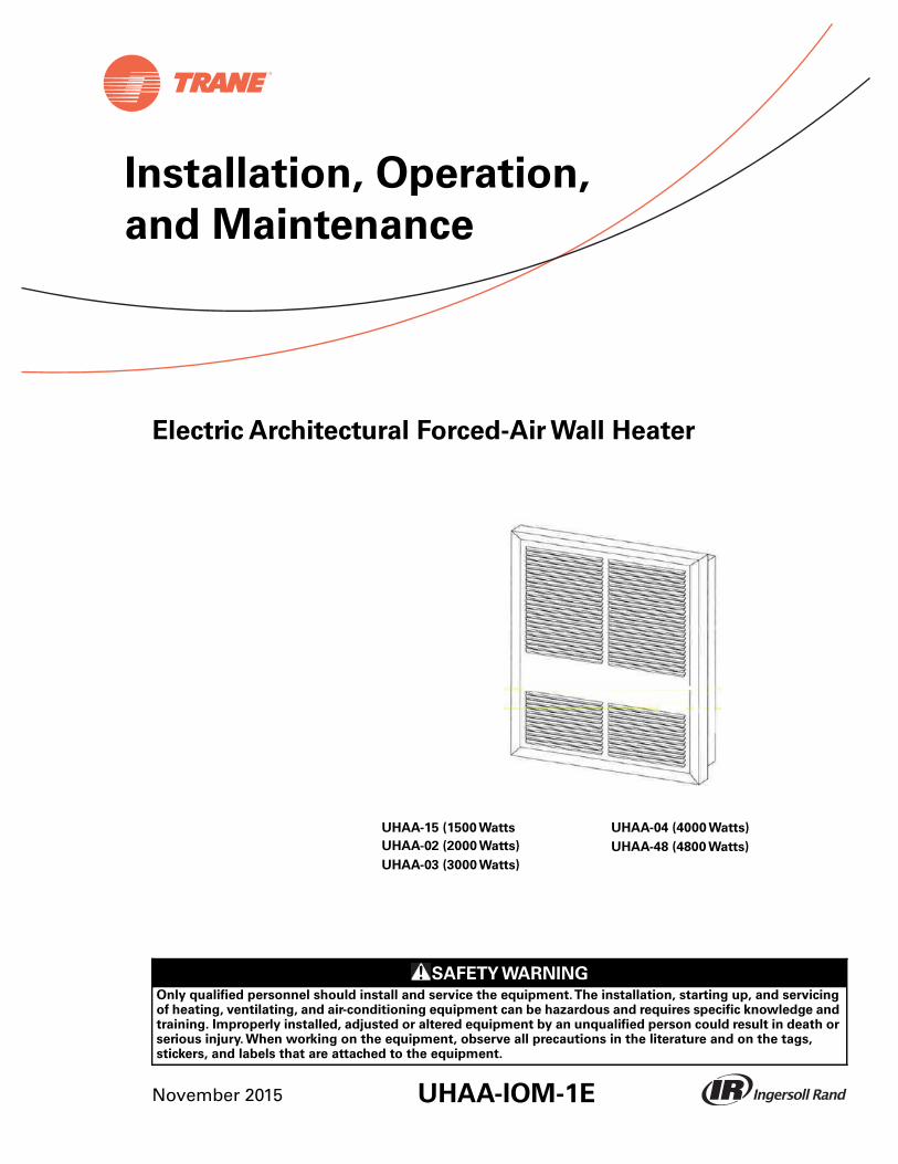
Electric Architectural Forced-Air Wall Heater
Installation, Operation,
and Maintenance
UHAA-15 (1500 Watts UHAA-04 (4000 Watts)
UHAA-02 (2000 Watts) UHAA-48 (4800 Watts)
UHAA-03 (3000 Watts)
UHAA-IOM-1ENovember 2015
Introduction
Warnings, Cautions, and Notices
Safety advisories appear throughout this manual as required.Your personal safety and the properoperation of this machine depend upon the strict observance of these precautions.
The three types of advisories are defined as follows:
WARNING Indicates a potentially hazardous situation which, if not avoided, could result indeath or serious injury.
CAUTIONsIndicates a potentially hazardous situation which, if not avoided, could result inminor or moderate injury. It could also be used to alert against unsafe practices.
NOTICEIndicates a situation that could result in equipment or property-damage onlyaccidents.
WARNING
Proper Field Wiring and Grounding Required!
Failure to follow code could result in death or serious injury. All field wiring MUST beperformed by qualified personnel. Improperly installed and grounded field wiring poses FIREand ELECTROCUTION hazards.To avoid these hazards, you MUST follow requirements for fieldwiring installation and grounding as described in NEC and your local/state electrical codes.Failure to follow code could result in death or serious injury.
WARNING
Personal Protective Equipment (PPE) Required!
Installing/servicing this unit could result in exposure to electrical, mechanical and chemicalhazards.
• Before installing/servicing this unit, technicians MUST put on all PPE required for the work
being undertaken (Examples; cut resistant gloves/sleeves, butyl gloves, safety glasses, hard
hat/bump cap, fall protection, electrical PPE and arc flash clothing). ALWAYS refer to
appropriate Material Safety Data Sheets (MSDS)/Safety Data Sheets (SDS) and OSHA
guidelines for proper PPE.
• When working with or around hazardous chemicals,ALWAYS refer to the appropriate MSDS/
SDS and OSHA/GHS (Global Harmonized System of Classification and Labelling of
Chemicals) guidelines for information on allowable personal exposure levels, proper
respiratory protection and handling instructions.
• If there is a risk of energized electrical contact, arc, or flash, technicians MUST put on all PPE
in accordance with OSHA, NFPA 70E, or other country-specific requirements for arc flash
protection, PRIOR to servicing the unit. NEVER PERFORM ANY SWITCHING,
DISCONNECTING, OR VOLTAGETESTING WITHOUT PROPER ELECTRICAL PPE AND ARC
FLASH CLOTHING. ENSURE ELECTRICAL METERSAND EQUIPMENTARE PROPERLY RATED
FOR INTENDED VOLTAGE.
Failure to follow instructions could result in death or serious injury.
© 2015Trane All rights reserved UHAA-IOM-1E
Introduction
Copyright
This document and the information in it are the property ofTrane, and may not be used orreproduced in whole or in part without written permission.Trane reserves the right to revise thispublication at any time, and to make changes to its content without obligation to notify any personof such revision or change.
Trademarks
All trademarks referenced in this document are the trademarks of their respective owners.
Revision History
• UHAA-IOM-1(September1990)
Original issue of manual, specifically intended for use by experienced service technicians. Providesinstallation procedures and operating instructions for "A" design sequence UHAA ElectricArchitectural Forced-Air Wall Heaters.
• UHAA-IOM-1A(April 1993) Metric dimensions added
• UHAA-IOM-1 B (May 1993) U. L. changes added to wiring diagram. Heater employs a visualalarm light to warn that parts of the heater are getting excessively hot.
• UHAA-IOM-1C (July 1994) Minor change in introduction.
• UHAA-IOM-10(April1997) Modified for Canadian use.
• UHAA-IOM-1E (Nov. 2015) U.L. standard update added page 6 for disconnect switch lockoutinstructions and revised Figure 7 wiring designations for Day/Night Relay.
UHAA-IOM-1E 3
Table of Contents
Model Number Codes . . . . . . . . . . . . . . . . . . . . . . . . . . . . . . . . . . . . . . . . . . . . . . 5
Important Precautions . . . . . . . . . . . . . . . . . . . . . . . . . . . . . . . . . . . . . . . . . . . . . . 6
Installation Instructions . . . . . . . . . . . . . . . . . . . . . . . . . . . . . . . . . . . . . . . . . . . . . 7
Locating the Heater . . . . . . . . . . . . . . . . . . . . . . . . . . . . . . . . . . . . . . . . . . . . . . 7
Before Mounting . . . . . . . . . . . . . . . . . . . . . . . . . . . . . . . . . . . . . . . . . . . . . . . . 8
Mounting Instructions . . . . . . . . . . . . . . . . . . . . . . . . . . . . . . . . . . . . . . . . . . . . 8
Wiring Instructions . . . . . . . . . . . . . . . . . . . . . . . . . . . . . . . . . . . . . . . . . . . . . . 9
Wiring Schematics . . . . . . . . . . . . . . . . . . . . . . . . . . . . . . . . . . . . . . . . . . . . . . . . 10
Operation and Maintenance . . . . . . . . . . . . . . . . . . . . . . . . . . . . . . . . . . . . . . . . 12
Pre-Start Procedures . . . . . . . . . . . . . . . . . . . . . . . . . . . . . . . . . . . . . . . . . . . . 12
Operating Instructions . . . . . . . . . . . . . . . . . . . . . . . . . . . . . . . . . . . . . . . . . . 12
Maintenance Instructions . . . . . . . . . . . . . . . . . . . . . . . . . . . . . . . . . . . . . . . . 13
4 UHAA-IOM-1E
Model Number Codes
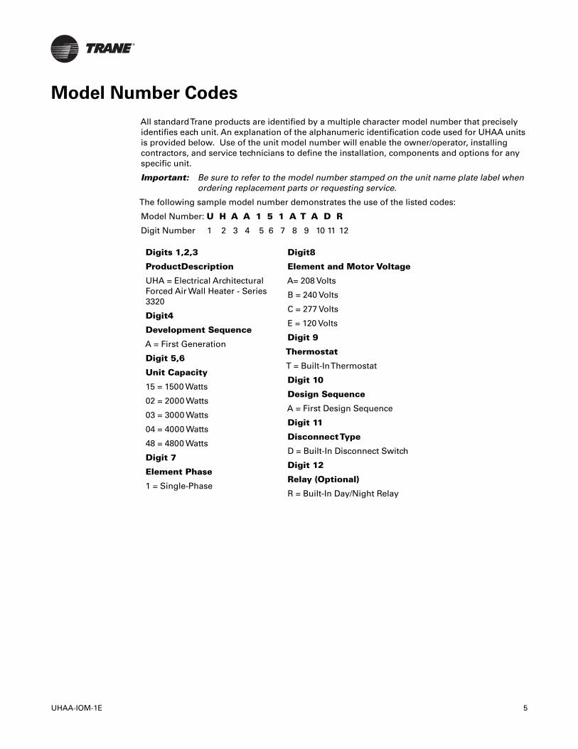
All standardTrane products are identified by a multiple character model number that preciselyidentifies each unit. An explanation of the alphanumeric identification code used for UHAA unitsis provided below. Use of the unit model number will enable the owner/operator, installingcontractors, and service technicians to define the installation, components and options for anyspecific unit.
Important: Be sure to refer to the model number stamped on the unit name plate label whenordering replacement parts or requesting service.
The following sample model number demonstrates the use of the listed codes:
Model Number: U H A A 1 5 1 A T A D R
Digit Number 1 2 3 4 5 6 7 8 9 10 11 12
Digits 1,2,3
ProductDescription
UHA = Electrical ArchitecturalForced Air Wall Heater - Series3320
Digit4
Development Sequence
A = First Generation
Digit 5,6
Unit Capacity
15 = 1500 Watts
02 = 2000 Watts
03 = 3000 Watts
04 = 4000 Watts
48 = 4800 Watts
Digit 7
Element Phase
1 = Single-Phase
Digit8
Element and Motor Voltage
A= 208 Volts
B = 240 Volts
C = 277 Volts
E = 120 Volts
Digit 9
Thermostat
T = Built-InThermostat
Digit 10
Design Sequence
A = First Design Sequence
Digit 11
DisconnectType
D = Built-In Disconnect Switch
Digit 12
Relay (Optional)
R = Built-In Day/Night Relay
UHAA-IOM-1E 5
Important Precautions
Important Precautions
When using electrical appliances, basic precautions should always be followed to reduce the riskof fire, electrical shock, and injury to persons, including the following:
• Read all instructions before using this heater.
• Keep cords and all other combustible material, such as furniture, papers, clothes and curtainsaway from the heater. For safe and efficient operation, keep an open space around heater ofthree feet in front and 12 inches at ends and rear.
• Extreme caution is necessary when any heater is used by or near children or invalids andwhenever the heater is left operating and unattended.
• Do not operate any heater after it malfunctions, has been dropped or damaged in any manner.Return heater to authorized service facility for examination, electrical or mechanicaladjustment, or repair.
• Do not use outdoors.
• To disconnect the heater, turn controls to off, and turn off power to heater circuit at maindisconnect panel (or operate internal disconnect switch if provided).
• Do not insert or allow foreign objects to enter any ventilation or exhaust opening as this maycause an electric shock.
• To prevent a possible fire, do not block air intakes or exhaust in any manner.
• Be aware that the heater has hot and arcing or sparking parts inside.
• WARNING: Do not use it in area where gasoline, paint, or flammable liquids are used or stored.
• Use this heater only as described in this manual. Any other use not recommended by themanufacturer may cause fire, electric shock, or injury to persons.
• This heater may include an audible or visual alarm to warn that parts of the heater are gettingexcessively hot.
• If the alarm sounds (or illuminates), immediately turn the heater off and inspect for any objectson or adjacent to the heater that may have blocked the airflow or otherwise caused hightemperatures to occur.
• DO NOT OPERATETHE HEATER WITHTHE ALARM SOUNDING (OR ILLUMINATING).
• SAVETHESE INSTRUCTIONS.
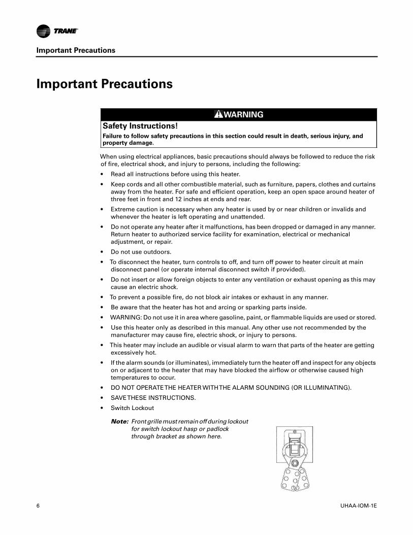
• Switch Lockout
WARNING
Safety Instructions!
Failure to follow safety precautions in this section could result in death, serious injury, andproperty damage.
Note: Front grille must remain off during lockoutfor switch lockout hasp or padlockthrough bracket as shown here.
6 UHAA-IOM-1E
Installation Instructions
Installation Instructions
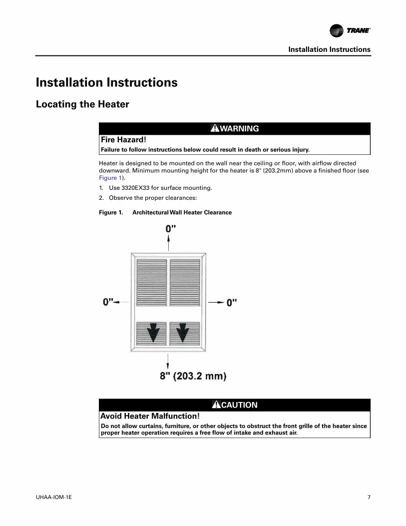
Locating the Heater
Heater is designed to be mounted on the wall near the ceiling or floor, with airflow directeddownward. Minimum mounting height for the heater is 8" (203.2mm) above a finished floor (seeFigure 1).
1. Use 3320EX33 for surface mounting.
2. Observe the proper clearances:
Figure 1. Architectural Wall Heater Clearance
WARNING
Fire Hazard!
Failure to follow instructions below could result in death or serious injury.
CAUTION
Avoid Heater Malfunction!
Do not allow curtains, furniture, or other objects to obstruct the front grille of the heater sinceproper heater operation requires a free flow of intake and exhaust air.
UHAA-IOM-1E 7
Installation Instructions
Before Mounting
1. Insure that supply voltage matches voltage rating on heater label.
2. Turn off electrical power to heater circuit.
Mounting Instructions
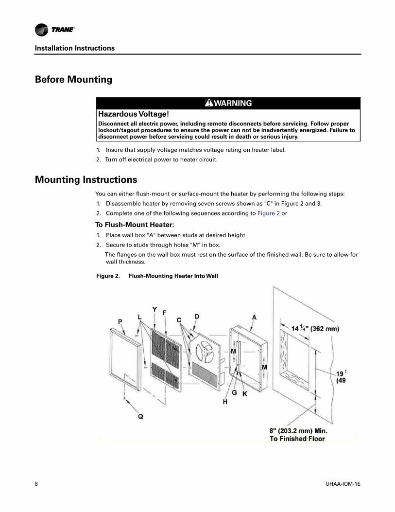
You can either flush-mount or surface-mount the heater by performing the following steps:
1. Disassemble heater by removing seven screws shown as "C" in Figure 2 and 3.
2. Complete one of the following sequences according to Figure 2 or
To Flush-Mount Heater:
1. Place wall box "A" between studs at desired height
2. Secure to studs through holes "M" in box.
The flanges on the wall box must rest on the surface of the finished wall. Be sure to allow forwall thickness.
Figure 2. Flush-Mounting Heater Into Wall
WARNING
Hazardous Voltage!
Disconnect all electric power, including remote disconnects before servicing. Follow properlockout/tagout procedures to ensure the power can not be inadvertently energized. Failure todisconnect power before servicing could result in death or serious injury.
8 UHAA-IOM-1E
Installation Instructions
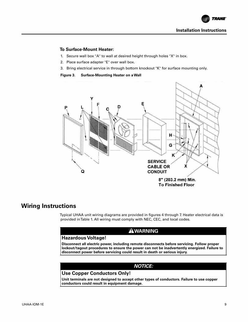
To Surface-Mount Heater:
1. Secure wall box "A" to wall at desired height through holes "X" in box.
2. Place surface adapter "E" over wall box.
3. Bring electrical service in through bottom knockout "K" for surface mounting only.
Figure 3. Surface-Mounting Heater on a Wall
Wiring Instructions
Typical UHAA unit wiring diagrams are provided in figures 4 through 7. Heater electrical data isprovided inTable 1. All wiring must comply with NEC, CEC, and local codes.
WARNING
Hazardous Voltage!
Disconnect all electric power, including remote disconnects before servicing. Follow properlockout/tagout procedures to ensure the power can not be inadvertently energized. Failure todisconnect power before servicing could result in death or serious injury.
NOTICE:
Use Copper Conductors Only!
Unit terminals are not designed to accept other types of conductors. Failure to use copperconductors could result in equipment damage.
UHAA-IOM-1E 9
Wiring Schematics
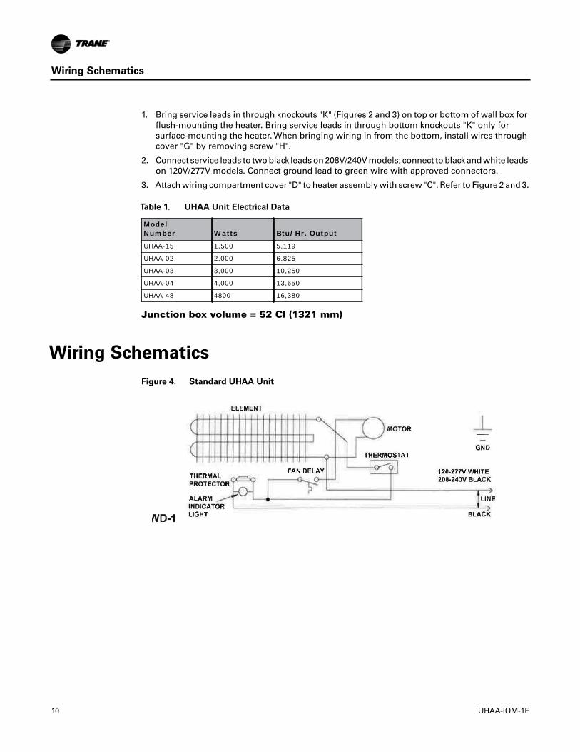
1. Bring service leads in through knockouts "K" (Figures 2 and 3) on top or bottom of wall box forflush-mounting the heater. Bring service leads in through bottom knockouts "K" only forsurface-mounting the heater. When bringing wiring in from the bottom, install wires throughcover "G" by removing screw "H".
2. Connect service leads to two black leads on 208V/240V models; connect to black and white leadson 120V/277V models. Connect ground lead to green wire with approved connectors.
3. Attach wiring compartment cover "D" to heater assembly with screw "C". Refer to Figure 2 and 3.
Junction box volume = 52 CI (1321 mm)
Wiring Schematics
Figure 4. Standard UHAA Unit
Table 1. UHAA Unit Electrical Data
ModelNumber Watts Btu/Hr. Output
UHAA-15 1,500 5,119
UHAA-02 2,000 6,825
UHAA-03 3,000 10,250
UHAA-04 4,000 13,650
UHAA-48 4800 16,380
10 UHAA-IOM-1E
Wiring Schematics
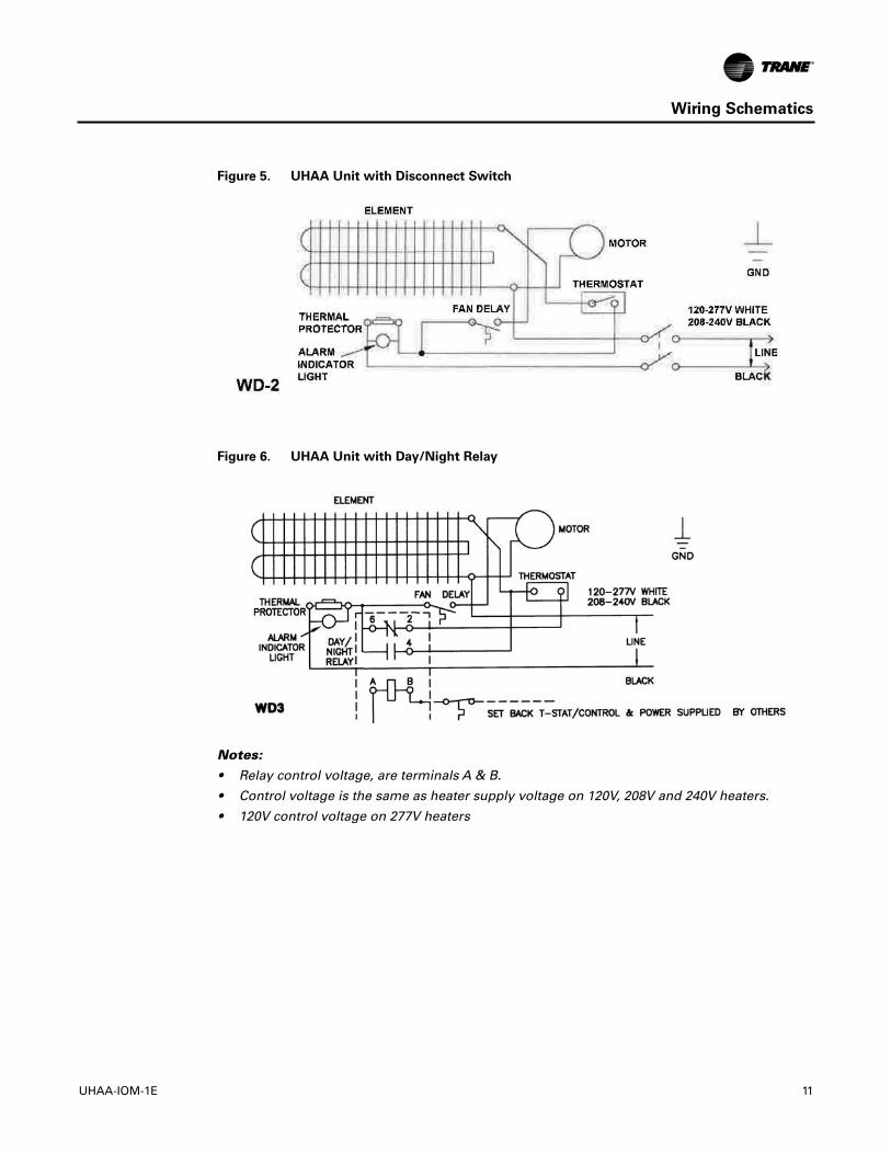
Figure 5. UHAA Unit with Disconnect Switch
Figure 6. UHAA Unit with Day/Night Relay
Notes:
• Relay control voltage, are terminals A & B.
• Control voltage is the same as heater supply voltage on 120V, 208V and 240V heaters.
• 120V control voltage on 277V heaters
UHAA-IOM-1E 11
Operation and Maintenance
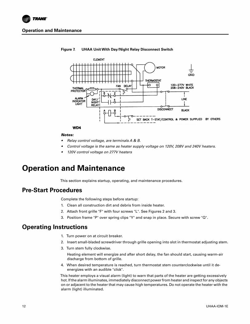
Figure 7. UHAA Unit With Day/Night Relay Disconnect Switch
Notes:
• Relay control voltage, are terminals A & B.
• Control voltage is the same as heater supply voltage on 120V, 208V and 240V heaters.
• 120V control voltage on 277V heaters
Operation and Maintenance
This section explains startup, operating, and maintenance procedures.
Pre-Start Procedures
Complete the following steps before startup:
1. Clean all construction dirt and debris from inside heater.
2. Attach front grille "F" with four screws "L". See Figures 2 and 3.
3. Position frame "P" over spring clips "Y" and snap in place. Secure with screw "Q".
Operating Instructions
1. Turn power on at circuit breaker.
2. Insert small-bladed screwdriver through grille opening into slot in thermostat adjusting stem.
3. Turn stem fully clockwise.
Heating element will energize and after short delay, the fan should start, causing warm-airdischarge from bottom of grille.
4. When desired temperature is reached, turn thermostat stem counterclockwise until it de-energizes with an audible "click".
This heater employs a visual alarm (light) to warn that parts of the heater are getting excessivelyhot. If the alarm illuminates, immediately disconnect power from heater and inspect for any objectson or adjacent to the heater that may cause high temperatures. Do not operate the heater with thealarm (light) illuminated.
12 UHAA-IOM-1E
Operation and Maintenance
Maintenance Instructions
1. Once a year, disconnect electrical power at power source.
2. Remove front grille from heater and clean dust from heater and grille.
3. Lubricate the motor with SAE No. 10 oil. Oil fittings are provided on front and back of motor.
4. Reassemble heater and restore electrical power to it.
WARNING
Hazardous Voltage!
Disconnect all electric power, including remote disconnects before servicing. Follow properlockout/tagout procedures to ensure the power can not be inadvertently energized. Failure todisconnect power before servicing could result in death or serious injury.
UHAA-IOM-1E 13

Notes

Trane optimizes the performance of homes and buildings around the world. A business of Ingersoll Rand, the leader increating and sustaining safe, comfortable and energy efficient environments,Trane offers a broad portfolio of advancedcontrols and HVAC systems, comprehensive building services, and parts. For more information, visit www.Trane.com.
Trane has a policy of continuous product and product data improvement and reserves the right to change design and specifications without notice.
We are committed to using environmentally
conscious print practices that reduce waste.
© 2015Trane All rights reserved
UHAA-IOM-1E 04 Nov 2015
Supersedes UHAA-IOM-1D 04 Apr 1997