installation, operation, and maintenance manual...handwheel operated valves (903, 913, 963)...
TRANSCRIPT

Industrial Process
Installation, Operation, andMaintenance ManualHandwheel Operated Valves (903, 913, 963)


Table of Contents
Introduction and Safety...................................................................................................................................................2Safety message levels.........................................................................................................................................................2User health and safety.......................................................................................................................................................2
Transportation and storage.............................................................................................................................................4Handling and unpacking guidelines................................................................................................................................4Storage, disposal, and return requirements...................................................................................................................4
Product Description..........................................................................................................................................................5Topworks identification....................................................................................................................................................5Bonnet description............................................................................................................................................................5Valve diaphragm identification........................................................................................................................................5
Installation...........................................................................................................................................................................7Install the valve and topworks.........................................................................................................................................7Tighten the bonnet fasteners...........................................................................................................................................7
Fastener torque table for valve body to topworks....................................................................................................8Set the travel stop..............................................................................................................................................................9
Operation...........................................................................................................................................................................11Topworks operation........................................................................................................................................................11
Maintenance......................................................................................................................................................................12Precautions.......................................................................................................................................................................12Inspection.........................................................................................................................................................................12Lubrication requirements...............................................................................................................................................12Disassemble the valve.....................................................................................................................................................12Replace the valve diaphragm.........................................................................................................................................13Change the diaphragm type...........................................................................................................................................15Replace the o-rings..........................................................................................................................................................15
Parts Listing and Cross-Sectional Drawings...........................................................................................................18963 PAS plastic bonnet...................................................................................................................................................18
Table of Contents
Handwheel Operated Valves (903, 913, 963) Installation, Operation, and Maintenance Manual 1

Introduction and SafetySafety message levelsDefinitions
Safety message level Indication
DANGER: A hazardous situation which, if not avoided, willresult in death or serious injury
WARNING: A hazardous situation which, if not avoided, couldresult in death or serious injury
CAUTION: A hazardous situation which, if not avoided, couldresult in minor or moderate injury
Electrical Hazard: The possibility of electrical risks if instructions arenot followed in a proper manner
NOTICE: • A potential situation which, if not avoided,could result in an undesirable result or state
• A practice not related to personal injury
User health and safetyGeneral precautions
This product is designed and manufactured using good workmanship and materials, and meets allapplicable industry standards. This product should be used only as recommended by an ITT engineer.
WARNING:• Misapplication of the valve can result in injury or property damage. Select valves and valve
components of the proper materials and make sure that they are consistent with your specificperformance requirements. Incorrect application of this product includes but is not limited to:• Exceeding the pressure or temperature rating• Failing to maintain this product according to the recommendations• Using this product to handle caustic or hazardous substances that it is not designed to handle
• If the product exhibits any indication of leakage, do not operate. Isolate the product and either repairit or replace it as outlined within this manual.
Introduction and Safety
2 Handwheel Operated Valves (903, 913, 963) Installation, Operation, and Maintenance Manual

Qualifications and trainingThe personnel responsible for the assembly, operation, inspection, and maintenance of the valve must beappropriately qualified. The operating company must do the following tasks:
• Define the responsibilities and competency of all personnel handling this equipment.• Provide instruction and training.• Ensure that the contents of the operating instructions have been fully understood by the personnel.
Instruction and training can be carried out by either ITT or the reseller of the valve by order of theoperating company.
Non-compliance risksFailure to comply with all safety precautions can result in the following conditions:
• Death or serious injury due to electrical, mechanical, and chemical influences• Environmental damage due to the leakage of dangerous materials• Product damage• Property damage• Loss of all claims for damages
Operational safety precautionsBe aware of these safety precautions when operating this product:
• Do not leave hot or cold components of the product unsecured against contact if they are a source ofdanger.
• Do not remove the contact guard for moving parts when the product is in operation. Never operatethe product without the contact guard installed.
• Do not hang items from the product. Any accessories must be firmly or permanently attached.• Do not use the product as a step or hand hold.• Do not paint over the identification tag, warnings, notices, or other identification marks associated
with the product.
Maintenance safety precautionsBe aware of these safety precautions when performing maintenance on this product:
• You must decontaminate the product if it has been exposed to harmful substances such as causticchemicals.
• You must immediately fit or reactivate all safety and protective equipment upon completion of work.
Use of unauthorized partsReconstruction or modification of the product is only permissible after consultation with ITT. Genuinespare parts and accessories authorized by ITT serve to maintain safety. Use of non-genuine ITT parts canannul liability of the manufacturer for the consequences. ITT parts are not to be used in conjunction withproducts not supplied by ITT as this improper use can annul all liability for the consequences.
Unacceptable modes of operationThe operational reliability of this product is only guaranteed when it is used as designated. The operatinglimits given on the identification tag and in the data sheet may not be exceeded under any circumstances. Ifthe identification tag is missing or worn, contact ITT for specific instructions.
Introduction and Safety
Handwheel Operated Valves (903, 913, 963) Installation, Operation, and Maintenance Manual 3

Transportation and storageHandling and unpacking guidelines
CAUTION:Always observe the applicable standards and regulations regarding the prevention of accidents whenhandling the product.
Handling guidelinesFollow these guidelines when handling the product to prevent damage:
• Use care when handling the product.• Leave protective caps and covers on the product until installation.
Unpacking guidelinesFollow these guidelines when unpacking the product:1. Inspect the package for damaged or missing items upon delivery.2. Note any damaged or missing items on the receipt and freight bill.3. If anything is out of order, file a claim with the shipping company.
Storage, disposal, and return requirementsStorage
If you are not immediately installing the product after delivery, store it as follows:• Store the product in a dry room that maintains a constant temperature.• Make sure that the products are not stacked on top of one another.
DisposalDispose of this product and associated components in compliance with federal, state, and local regulations.
ReturnEnsure these requirements are met before you return a product to ITT:
• Contact ITT for specific instructions on how to return the product.• Clean the valve of all hazardous material.• Complete a Material Safety Data Sheet or Process Data Sheet for any process fluid that could remain
on the valve.• Obtain a Return Material Authorization from the factory.
Transportation and storage
4 Handwheel Operated Valves (903, 913, 963) Installation, Operation, and Maintenance Manual

Product DescriptionTopworks identificationModel number
Code Description
903 Cast iron bonnet with rising stem and travel stop903S Cast iron sealed bonnet with rising stem and travel stop913 Stainless steel bonnet with rising stem and travel stop913S Stainless steel sealed bonnet with rising stem and travel stop963 PAS plastic bonnet with rising handwheel and travel stop963S PAS plastic sealed bonnet with rising handwheel and travel stop
Identification tag
Bonnet descriptionNon-Sealed bonnet
The non-sealed bonnet has a weep hole that permits leakage of the process fluid if the diaphragmruptures.
Sealed bonnetThe sealed bonnet uses a special “V-notch” vent plug, which permits diaphragm inspection.
Figure 1: Weep hole and V-notch vent plug
Bonnet weep hole
V-notch vent plug(Sealed bonnet only)
Valve diaphragm identificationDiaphragm tab codes
All diaphragm materials and physical properties are batch traceable via permanent codes molded into thediaphragm tabs. The molding date, grade of diaphragm, and valve size provide traceability to original batchrecords.
Product Description
Handwheel Operated Valves (903, 913, 963) Installation, Operation, and Maintenance Manual 5

Supplier code
Date code
Figure 2: Elastomer diaphragm front
Grade of diaphragm
Valve size
Figure 3: Elastomer diaphragm back
Date code
Material code
Figure 4: PTFE diaphragm
Product Description
6 Handwheel Operated Valves (903, 913, 963) Installation, Operation, and Maintenance Manual

InstallationInstall the valve and topworks
NOTICE:The topworks size and configuration can limit the actual operating pressure. Consult the engineeringcatalog for topworks sizing. Consult the factory or engineering catalog for vacuum operation.
1. If you have a weld end valve, then consider the following:
If you are welding ... Then ...Manually Remove the topworks.
Remove the diaphragm.
In line for schedule 10 or heavierpipe
Remove the topworks.Remove the diaphragm.
In line for schedule 5 or lighterpipe and tubing
You can weld with automatic equipment. Before you performthe weld:1. Do not remove the topworks.2. Set the valve to the open position.3. Properly purge the valve with an inert gas.
2. Install the valve.Install with the raised hash marks (castings) or small machined dots (forgings) on the valve body at the12 o’clock position to achieve the optimum drain angle.
3. Prior to pressurization (with the valve slightly open), tighten the bonnet fasteners.For more information, see Tighten the bonnet fasteners (page 7).
4. Cycle the valve two to three times to verify smooth operation.5. Set the travel stop.
For more information, see Set the travel stop (page 9).
Tighten the bonnet fastenersCAUTION:Do not tighten fasteners while the system is pressurized or at elevated temperatures (greater than 100°F(38°C)).
1. Depressurize the system.2. Position diaphragm so that valve is slightly open.
For valves with an actuator, you may need to use regulated air pressure to actuate the valve.3. Tighten the bonnet fasteners in a crisscross pattern.
Installation
Handwheel Operated Valves (903, 913, 963) Installation, Operation, and Maintenance Manual 7
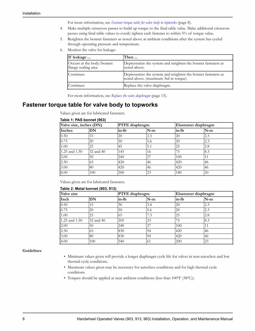
For more information, see Fastener torque table for valve body to topworks (page 8).4. Make multiple crisscross passes to build up torque to the final table value. Make additional crisscross
passes using final table values to evenly tighten each fastener to within 5% of torque value.5. Retighten the bonnet fasteners as noted above at ambient conditions after the system has cycled
through operating pressure and temperature.6. Monitor the valve for leakage:
If leakage ... Then ...Occurs at the body/bonnetflange sealing area
Depressurize the system and retighten the bonnet fasteners asnoted above.
Continues Depressurize the system and retighten the bonnet fasteners asnoted above. (maximum 3rd re-torque)
Continues Replace the valve diaphragm.
For more information, see Replace the valve diaphragm (page 13).
Fastener torque table for valve body to topworksValues given are for lubricated fasteners.
Table 1: PAS bonnet (963)Valve size, inches (DN) PTFE diaphragm Elastomer diaphragmInches DN in-lb N-m in-lb N-m0.50 15 20 2.3 20 2.30.75 20 50 5.6 20 2.31.00 25 45 5.1 25 2.81.25 and 1.50 32 and 40 145 16 75 8.32.00 50 240 27 100 112.50 65 420 46 420 463.00 80 420 46 420 464.00 100 200 23 180 20
Values given are for lubricated fasteners.
Table 2: Metal bonnet (903, 913)Valve size PTFE diaphragm Elastomer diaphragmInch DN in-lb N-m in-lb N-m0.50 15 30 3.4 20 2.30.75 20 50 5.6 20 2.31.00 25 65 7.3 25 2.81.25 and 1.50 32 and 40 205 23 75 8.32.00 50 240 27 100 112.50 65 830 94 420 463.00 80 830 94 420 464.00 100 540 61 200 23
Guidelines• Minimum values given will provide a longer diaphragm cycle life for valves in non-autoclave and low
thermal cycle conditions.• Maximum values given may be necessary for autoclave conditions and for high thermal cycle
conditions.• Torques should be applied at near ambient conditions (less than 100ºF (38ºC)).
Installation
8 Handwheel Operated Valves (903, 913, 963) Installation, Operation, and Maintenance Manual

Set the travel stop1. Do you have a test fixture?
• If Yes: Follow steps 2 through 6.• If No: Proceed to step 7.
23
4
1
1. Stop nut2. Air supply3. Tubing4. Beaker of water
2. Supply air pressure equal to the system operating pressure to one side of the valve.3. Cap the other side of the valve and install a venting rubber or plastic tube.4. Hold the tube in a container of water.5. Turn the handwheel closed until the leakage stops.
Air bubbles indicate leakage.6. Adjust the travel stop nut tight against the spacer.7. Do you have a weir valve?
• If Yes: Follow the steps below.• If No: You must set the travel stop with a test fixture, following the instructions above.
8. If you have an elastomer diaphragm, then follow the steps below:a) Remove pressure from the line containing the valve.b) Remove the bonnet fasteners, nuts, and bonnet.c) Unscrew the diaphragm from the compressor.d) Replace the bonnet on the valve body without a diaphragm.e) Replace two bonnet fasteners and nuts on opposite sides of the bonnet and hand tighten.f) Turn the handwheel until the compressor touches the weir.
The valve will not close further.g) Screw the travel stop nut down until it seats on the spacer.h) Remove the bonnet from the valve body.
Installation
Handwheel Operated Valves (903, 913, 963) Installation, Operation, and Maintenance Manual 9

i) Screw a diaphragm into the compressor and hand tighten. Back off the diaphragm until the boltholes in the diaphragm and bonnet flange align.
j) Rotate the handwheel counterclockwise just enough to permit the flange area of the diaphragm torest flat against the flange area of the bonnet.
k) Replace the bonnet on the valve body.The bonnet should be opened one half to one turn of the handwheel.
l) Tighten the bonnet fasteners.For more information, see Tighten the bonnet fasteners in Installation.
9. If you have a PTFE diaphragm, then follow the steps below:a) Loosen the lock nut.b) Turn the handwheel clockwise until you feel the initial resistance of the diaphragm seating. From
this point, turn the handwheel another 5/8 turn.c) Turn the lock nut down until it bottoms on the spacer.
Installation
10 Handwheel Operated Valves (903, 913, 963) Installation, Operation, and Maintenance Manual

OperationTopworks operation
The valve is closed with a clockwise rotation of the handwheel.Valve size Stem travel Number of turns
Inch DN Inch mm
0.50 15 0.25 6.4 20.75 20 0.38 9.5 31.00 25 0.50 13 41.25 and 1.50 32 and 40 0.81 21 4.882.00 50 1.12 29 6.752.50 65 1.61 41 8.123.00 80 1.61 41 8.124.00 100 2.12 54 10.626.00 150 3.12 79 10.62
Operation
Handwheel Operated Valves (903, 913, 963) Installation, Operation, and Maintenance Manual 11

MaintenancePrecautions
WARNING:• All procedures must be performed by qualified personnel.• When the process fluid is hazardous, thermal (hot or cold), or corrosive, take extra precautions.
Employ the appropriate safety devices and be prepared to control a process media leak.• Always wear protective clothing and equipment to safeguard the eyes, face, hands, skin, and lungs
from the particular fluid in the line.
InspectionInspection area What to look for Action if problem is foundExternal valve parts Excessive wear or corrosion • Replace the affected parts
• Contact ITT to obtainreplacement parts or forspecific instructions
Non sealed bonnet Fluid weeping from the weep hole Replace the valve diaphragmSealed bonnet Fluid weeping from the plug
Loosen the v-notch vent plug 2-3turns to check
Replace the valve diaphragm
Topworks Spindle binding, excessive noise,or dried lubricant
Lubricate the topworks
Diaphragm and valve body Leakage between the diaphragmand valve body
Tighten the bonnet fasteners
For more information, see:• Replace the valve diaphragm in this manual.• Lubrication requirements in this manual.• Tighten the bonnet fasteners in this manual.
Lubrication requirementsWARNING:Standard lubricants are as outlined below. Special lubricants may be required for oxygen or other uniqueservices. Contact ITT for evaluation of non-standard lubricants.
Lubrication scheduleRemove residual grease prior to re-lubrication. Lubricate the spindle threads, thrust bearing, lower spindleface and neck where it interfaces with the compressor, and o-ring whenever the topworks is disassembled.Bonnets are not equipped with grease fittings and must be disassembled to be lubricated.
Acceptable lubricantsBrand Lubricant typeChevron FM ALC EP 2 (FDA Compliant)
Disassemble the valve1. Remove all line pressure.
Maintenance
12 Handwheel Operated Valves (903, 913, 963) Installation, Operation, and Maintenance Manual

2. Turn the valve to the open position counter clockwise at least one turn.3. Remove the bonnet fasteners.4. Lift the topworks assembly from the valve body.
Replace the valve diaphragm1. Disassemble the valve.
For more information, see Disassemble the valve in this manual.2. Unscrew the diaphragm from the compressor by turning the diaphragm counterclockwise.
The replacement diaphragm should be identical in size and grade to the original diaphragm.3. If replacing a PTFE diaphragm, follow these steps.
a) Install the new elastomer backing cushion over the tube nut.
b) Invert the PTFE diaphragm by pressing the center of the diaphragm face with your thumbs whileholding the edge of the diaphragm with your fingers.
c) Engage the threads of the diaphragm into the tube nut by rotating clockwise.
d) Continue rotating the PTFE diaphragm clockwise into the compressor while securing the backingcushion from rotating.
Maintenance
Handwheel Operated Valves (903, 913, 963) Installation, Operation, and Maintenance Manual 13

4. Rotate the diaphragm until hard stop or heavy resistance is achieved and additional force does notsignificantly rotate the diaphragm into the compressor.
5. If replacing a PTFE diaphragm, re-invert the diaphragm.
6. Back off (no more than half turn) until the bolt holes in diaphragm and the bonnet flange align.
Maintenance
14 Handwheel Operated Valves (903, 913, 963) Installation, Operation, and Maintenance Manual

7. Rotate the handwheel counterclockwise just enough to permit the flange area of the diaphragm to restflat against the flange area of the bonnet.
8. Replace the topworks assembly on the body and tighten the bonnet fasteners.For more information, see Tighten the bonnet fasteners (page 7).
9. Set the travel stop.For more information, see Set the travel stop (page 9).
Change the diaphragm type1. Remove the bonnet nuts and lift off the bonnet.2. Remove the plastic cap and travel stop nut.3. Loosen the handwheel setscrew(s) and remove the handwheel from the bonnet.4. Remove the diaphragm, spindle and bushing assembly by withdrawing it through bottom of bonnet.5. Remove the compressor.If the compressor to spindle connection is a ...Then ...Spring pin Drive out the spring pin that retains the
compressor"T" slot Slide the compressor off the spindle
6. Change to the new compressor.If you are changing ... Then ...From an elastomer to a PTFE diaphragm Install a tube nut into the hexagonal hole in the
new compressorFrom a PTFE to an elastomer diaphragm Change to the new compressor.
7. Install the new compressor.If the compressor to spindle connection is a ...Then ...Spring pin Locate the new compressor on the spindle and
drive in the spring pin“T” slot Slide the new compressor onto the spindle
Replace the o-rings1. Disassemble the topworks:
a) Remove the bonnet nuts and lift off the bonnet.b) Remove the plastic cap and travel stop nut.c) Loosen the handwheel setscrews and remove the handwheel from the bonnet.d) Remove the diaphragm, spindle, and bushing assembly by withdrawing it through the bottom of
the bonnet.2. Remove o-ring 1 from the groove in the bushing outside diameter.
Maintenance
Handwheel Operated Valves (903, 913, 963) Installation, Operation, and Maintenance Manual 15

2
3
1
Figure 5: O-rings for 0.50–2.00 inch (DN15–50) valve
1. O-ring 12. O-ring 23. O-ring 3
2
3
4
1
Figure 6: O-rings for 2.50–4.00 inch (DN 65–100)valve
1. O-ring 12. O-ring 23. O-ring 34. O-ring 4
3. Unscrew the diaphragm and spindle assembly from the handwheel bushing.4. Remove o-rings:Valve size (in) Valve size (DN) Action.5–2 15–50 Remove o-ring 2 from the
groove in spindle outsidediameter.
2.5–6 80–150 Remove o-rings 2 and 4 from thespindle plug.
5. Install the thrust bearing or washer:a) Lubricate the thrust bearing or washer.
For more information, see Lubrication requirements (page 12).b) Install the thrust bearing or washer on the shoulder of the bushing.
6. Cover the stem threads with masking tape to protect the o-rings during installation.7. Lubricate o-rings.
For more information, see Lubrication requirements (page 12).
Maintenance
16 Handwheel Operated Valves (903, 913, 963) Installation, Operation, and Maintenance Manual

Valve size (in) Valve size (DN) Action.5–2 15–50 Lubricate o-rings 1 and 2 and
insert them into the grooves inthe bushing and spindle.
2.5–6 80–150 Lubricate o-rings 2 and 4 andinsert them into the grooves inthe spindle plug.
Select the proper o-rings for the valve size.Valve size, inches (DN) O-ring 1 O-ring 2 O-ring 4
0.50 (15) .445 x .063 #107 –0.75 (20) .571 x .063 #109 –1.00 (25) .634 x .063 #110 –1.25 (32) #119 #112 –1.50 (40) #119 #112 –2.00 (50) #119 #112 –2.50 (65) #218 #209 #2123.00 (80) #218 #209 #2124.00 (100) #220 #210 #214
8. Remove the masking tape from the stem threads.9. Screw the diaphragm and spindle assembly into the bushing.10. Install the diaphragm, spindle, and bushing assembly into the bonnet.
Verify that the shim washer is installed.11. Install the handwheel:
a) Tighten the setscrews, ensuring the setscrew ends engage the bushing holes.b) If you do not have a plastic handwheel, then use a thread locking compound.
12. Install o-ring 3 and screw the cap onto the bushing hand tight.Select the proper o-ring for the valve size.
Valve size, inches (DN) O-ring 3
0.50 (15) #1180.75 (20) #1191.00 (25) #1211.25 (32) #1221.50 (40) #1222.00 (50) #1222.50 (65) #1283.00 (80) #1284.00 (100) #130
Maintenance
Handwheel Operated Valves (903, 913, 963) Installation, Operation, and Maintenance Manual 17

Parts Listing and Cross-Sectional Drawings963 PAS plastic bonnetList of parts
1
2
3
45
6
78910
1112
1314
15
16
17
18
19
20
21
22
23
24
Figure 7
25
26
19
27
18
28
Figure 8: Bonnet and bolting detail for fabricationswith studs
29
Figure 9: V-notch vent plug for sealedbonnet
Parts Listing and Cross-Sectional Drawings
18 Handwheel Operated Valves (903, 913, 963) Installation, Operation, and Maintenance Manual

Item Description Material Quantity
11 Spindle Stainless steel (0.5–2 in (DN15–50)Carbon steel (3–4 in (DN80–100)2
1
2 Locknut Stainless steel 43 Washer Stainless steel 14 Wiper seal Viton
Polyolefin foam1
5 O-ring Viton 16 Screw Stainless steel 1 or 27 O-ring Viton 18 O-ring Viton 19 Thrust bearing Polyethylene As required10 Bushing Brass 1111 Compressor Bronze or stainless steel 1123 Spirol pin Silicone 113 Tube nut Brass 114 Backing cushion EPDM 115 Diaphragm PTFE 116 Metal body Stainless steel 117 Cap screw Stainless steel 418 Plain washer Stainless steel 419 Bonnet Polyarylsulfone 120 Hex nut Stainless steel 421 Nut cover cap Polyarylsulfone 422 Shim washer Polyethylene As required23 Handwheel Polyarylsulfone 124 Cap Polyphenylsulfone 1254 Stud Stainless steel 426 Spacer Stainless steel 427 Body Stainless steel 1284 Hex nut Stainless steel 429 V-notch vent plug Stainless steel 1
1 Sanitary internals include a stainless steel spindle and bronze compressor.2 For 3–4 in. (DN80–100) sanitary internals are optional.3 For “T” slot connection between spindle and compressor, the spirol pin is not used.4 ASME grade fasteners are available on tank botton valve.
Parts Listing and Cross-Sectional Drawings
Handwheel Operated Valves (903, 913, 963) Installation, Operation, and Maintenance Manual 19


Visit our Web site for the latest version of this document and more informationhttp://www.ittpureflo.com
ITT Pure-Flo33 Centerville RaodLancaster, PA 17603USATel. 1–717–509–2200Fax (717) 509–2316
ITT Pure-FloRichards Street, KirkhamLancashire PR4 2HUEnglandTel. +44-1772-682696Fax +44-1772-686006
© 2010 ITT Corporation. The original instruction is in English. All non-English instructions are translations of the originalinstruction. HWO-IOM