installation, operation and maintenance · this manual provides instructions for the installation,...
TRANSCRIPT

Installation, Operation and Maintenance
Model 3910 11th Edition (ISO 13709)

FOREWORDThis manual provides instructions for the Installation, Operation, and Maintenance of the Goulds
Model 3910 Vertical Bearing Frame In-line Process Pump designed to meet the requirements of
the 11th Edition (ISO 13709) of API* Standard 610. This manual covers the standard product
plus common options that are available. For special options, supplemental instructions are
supplied. This manual must be read and understood before installation and maintenance.
The design, materials, and workmanship incorporated in the construction of Goulds pumps make them
capable of giving long, trouble-free service. The life and satisfactory service of any mechanical unit,
however, are enhanced and extended by correct application, proper installation, periodic inspection,
condition monitoring, and careful maintenance. This instruction manual was prepared to assist operators
in understanding the construction and the correct methods of installing, operating, and maintaining these
pumps.
ITT - Goulds Pumps shall not be liable for physical injury, damage or delays caused by a failure
to observe the instructions for installation, operation, and maintenance contained in this manual.
� When pumping unit is installed in a potentially explosive atmosphere, the instructions after the Ex symbol must befollowed. Personal injury and/or equipment damage may occur if these instructions are not followed. If there is anyquestion regarding these requirements or if the equipment is to be modified, please contact a Goulds representativebefore proceeding.
Warranty is valid only when genuine ITT - Goulds Pumps parts are used.
Use of the equipment on a service other than stated in the order will nullify the warranty, unless written
approval is obtained in advance from ITT - Goulds Pumps.
Supervision by an authorized ITT - Goulds representative is recommended to assure proper installation.
Additional manuals can be obtained by contacting your local ITT - Goulds representative or by calling
1-(800)-446-8537.
THIS MANUAL EXPLAINS
� Proper Installation
� Start-up Procedures
� Operation Procedures
� Routine Maintenance
� Pump Overhaul
� Troubleshooting
� Ordering Spare or Repair Parts
3910-11th IOM 5/08 5
* American Petroleum Institute
1220 L Street, Northwest
Washington, D.C. 20005

TABLE OF CONTENTSPAGE
9 SAFETY
13 GENERAL INFORMATION
17 INSTALLATION
21 OPERATION
27 PREVENTIVE MAINTENANCE
31 DISASSEMBLY & REASSEMBLY
61 SPARE PARTS
63 APPENDICES
I - 63 Installation & Disassembly Instructions for Goulds ANSI B15.1 Coupling Guards
A - 63 (Casing Mount Motor Support Only) - All Power Ends Except those with
Optional Air Cooling Package
B - 67 (Casing Mount Motor Support Only) - Power Ends with Optional Air Cooling
Package
II - 71 Dial Indicator (Rim-and-Face) Alignment Procedure
III -75 Removal and Installation of Back Pull-Out Assembly Using Goulds Back Pull-Out
Removal Device
3910-11th IOM 5/08 7
1
3
4
5
7
8
6
SECTION
2

8 3910-11th IOM 5/08

S-1
IMPORTANT SAFETY NOTICE
To: Our Valued Customers
User safety is a major focus in the design of our products. Following the precautions outlined in this manual will minimize your risk of injury.
ITT Goulds pumps will provide safe, trouble-free service when properly installed, maintained, and operated.
Safe installation, operation, and maintenance of ITT Goulds Pumps equipment are an essential end user responsibility. This Pump Safety Manual identifies specific safety risks that must be considered at all times during product life. Understanding and adhering to these safety warnings is mandatory to ensure personnel, property, and/or the environment will not be harmed. Adherence to these warnings alone, however, is not sufficient — it is anticipated that the end user will also comply with industry and corporate safety standards. Identifying and eliminating unsafe installation, operating and maintenance practices is the responsibility of all individuals involved in the installation, operation, and maintenance of industrial equipment.
Please take the time to review and understand the safe installation, operation, and maintenance guidelines outlined in this Pump Safety Manual and the Instruction, Operation, and Maintenance (IOM) manual. Current manuals are available at www.gouldspumps.com/literature_ioms.html or by contacting your nearest Goulds Pumps sales representative.
These manuals must be read and understood before installation and start-up.
For additional information, contact your nearest Goulds Pumps sales representative or visit our Web site at www.gouldspumps.com.

S-2
SAFETY WARNINGS
Specific to pumping equipment, significant risks bear reinforcement above and beyond normal safety precautions.
WARNING
A pump is a pressure vessel with rotating parts that can be hazardous. Any pressure vessel can explode, rupture, or discharge its contents if sufficiently over pressurized causing death, personal injury, property damage, and/or damage to the environment. All necessary measures must be taken to ensure over pressurization does not occur.
WARNING
Operation of any pumping system with a blocked suction and discharge must be avoided in all cases. Operation, even for a brief period under these conditions, can cause superheating of enclosed pumpage and result in a violent explosion. All necessary measures must be taken by the end user to ensure this condition is avoided.
WARNING
The pump may handle hazardous and/or toxic fluids. Care must be taken to identify the contents of the pump and eliminate the possibility of exposure, particularly if hazardous and/or toxic. Potential hazards include, but are not limited to, high temperature, flammable, acidic, caustic, explosive, and other risks.
WARNING
Pumping equipment Instruction, Operation, and Maintenance manuals clearly identify accepted methods for disassembling pumping units. These methods must be adhered to. Specifically, applying heat to impellers and/or impeller retaining devices to aid in their removal is strictly forbidden. Trapped liquid can rapidly expand and result in a violent explosion and injury.
ITT Goulds Pumps will not accept responsibility for physical injury, damage, or delays caused by a failure to observe the instructions for installation, operation, and maintenance contained in this Pump Safety Manual or the current IOM available at www.gouldspumps.com/literature.

S-3
SAFETY DEFINITIONS Throughout this manual the words WARNING, CAUTION, ELECTRICAL, and ATEX are used to indicate where special operator attention is required.
Observe all Cautions and Warnings highlighted in this Pump Safety Manual and the IOM provided with your equipment.
WARNING Indicates a hazardous situation which, if not avoided, could result in death or serious injury.
Example: Pump shall never be operated without coupling guard installed correctly.
CAUTION Indicates a hazardous situation which, if not avoided, could result in minor or moderate injury.
Example: Throttling flow from the suction side may cause cavitation and pump damage.
ELECTRICAL HAZARD Indicates the possibility of electrical risks if directions are not followed.
Example: Lock out driver power to prevent electric shock, accidental start-up, and physical injury.
When installed in potentially explosive atmospheres, the instructions that follow the Ex symbol must be followed. Personal injury and/or equipment damage may occur if these instructions are not followed. If there is any question regarding these requirements or if the equipment is to be modified, please contact an ITT Goulds Pumps representative before proceeding.
Example: Improper impeller adjustment could cause contact between the rotating and stationary parts, resulting in a spark and heat generation.

S-4
GENERAL PRECAUTIONS
WARNING
A pump is a pressure vessel with rotating parts that can be hazardous. Hazardous fluids may be contained by the pump including high temperature, flammable, acidic, caustic, explosive, and other risks. Operators and maintenance personnel must realize this and follow safety measures. Personal injuries will result if procedures outlined in this manual are not followed. ITT Goulds Pumps will not accept responsibility for physical injury, damage or delays caused by a failure to observe the instructions in this manual and the IOM provided with your equipment.
General Precautions
WARNING NEVER APPLY HEAT TO REMOVE IMPELLER. It may explode due to trapped liquid.
WARNING NEVER use heat to disassemble pump due to risk of explosion from tapped liquid.
WARNING NEVER operate pump without coupling guard correctly installed.
WARNING NEVER run pump below recommended minimum flow when dry, or without prime.
WARNING ALWAYS lock out power to the driver before performing pump maintenance.
WARNING NEVER operate pump without safety devices installed.
WARNING NEVER operate pump with discharge valve closed.
WARNING NEVER operate pump with suction valve closed.
WARNING DO NOT change service application without approval of an authorized ITT Goulds Pumps representative.
WARNING
Safety Apparel: Insulated work gloves when handling hot bearings or using bearing heater Heavy work gloves when handling parts with sharp edges, especially impellers
Safety glasses (with side shields) for eye protection Steel-toed shoes for foot protection when handling parts, heavy tools, etc. Other personal protective equipment to protect against hazardous/toxic fluids
WARNING
Receiving: Assembled pumping units and their components are heavy. Failure to properly lift and support equipment can result in serious physical injury and/or equipment damage. Lift equipment only at specifically identified lifting points or as instructed in the current IOM. Current manuals are available at www.gouldspumps.com/literature_ioms.html or from your local ITT Goulds Pumps sales representative. Note: Lifting devices (eyebolts, slings, spreaders, etc.) must be rated, selected, and used for the entire load being lifted.
WARNING
Alignment: Shaft alignment procedures must be followed to prevent catastrophic failure of drive components or unintended contact of rotating parts. Follow coupling manufacturer’s coupling installation and operation procedures.

S-5
General Precautions
WARNING Before beginning any alignment procedure, make sure driver power is locked out. Failure to lock out driver power will result in serious physical injury.
CAUTION
Piping: Never draw piping into place by forcing at the flanged connections of the pump. This may impose dangerous strains on the unit and cause misalignment between pump and driver. Pipe strain will adversely effect the operation of the pump resulting in physical injury and damage to the equipment.
WARNING Flanged Connections: Use only fasteners of the proper size and material.
WARNING Replace all corroded fasteners.
WARNING Ensure all fasteners are properly tightened and there are no missing fasteners.
WARNING Startup and Operation: When installing in a potentially explosive environment, please ensure that the motor is properly certified.
WARNING Operating pump in reverse rotation may result in contact of metal parts, heat generation, and breach of containment.
WARNING Lock out driver power to prevent accidental start-up and physical injury.
WARNING The impeller clearance setting procedure must be followed. Improperly setting the clearance or not following any of the proper procedures can result in sparks, unexpected heat generation and equipment damage.
WARNING If using a cartridge mechanical seal, the centering clips must be installed and set screws loosened prior to setting impeller clearance. Failure to do so could result in sparks, heat generation, and mechanical seal damage.
WARNING The coupling used in an ATEX classified environment must be properly certified and must be constructed from a non-sparking material.
WARNING Never operate a pump without coupling guard properly installed. Personal injury will occur if pump is run without coupling guard.
WARNING Make sure to properly lubricate the bearings. Failure to do so may result in excess heat generation, sparks, and / or premature failure.
CAUTION The mechanical seal used in an ATEX classified environment must be properly certified. Prior to start up, ensure all points of potential leakage of process fluid to the work environment are closed.
CAUTION Never operate the pump without liquid supplied to mechanical seal. Running a mechanical seal dry, even for a few seconds, can cause seal damage and must be avoided. Physical injury can occur if mechanical seal fails.
WARNING Never attempt to replace packing until the driver is properly locked out and the coupling spacer is removed.
WARNING Dynamic seals are not allowed in an ATEX classified environment.
WARNING DO NOT operate pump below minimum rated flows or with suction and/or discharge valve closed. These conditions may create an explosive hazard due to vaporization of pumpage and can quickly lead to pump failure and physical injury.

S-6
General Precautions
WARNING Ensure pump is isolated from system and pressure is relieved before disassembling pump, removing plugs, opening vent or drain valves, or disconnecting piping.
WARNING
Shutdown, Disassembly, and Reassembly: Pump components can be heavy. Proper methods of lifting must be employed to avoid physical injury and/or equipment damage. Steel toed shoes must be worn at all times.
WARNING
The pump may handle hazardous and/or toxic fluids. Observe proper decontamination procedures. Proper personal protective equipment should be worn. Precautions must be taken to prevent physical injury. Pumpage must be handled and disposed of in conformance with applicable environmental regulations.
WARNING Operator must be aware of pumpage and safety precautions to prevent physical injury.
WARNING Lock out driver power to prevent accidental startup and physical injury.
CAUTION Allow all system and pump components to cool before handling them to prevent physical injury.
CAUTION
If pump is a Model NM3171, NM3196, 3198, 3298, V3298, SP3298, 4150, 4550, or 3107, there may be a risk of static electric discharge from plastic parts that are not properly grounded. If pumped fluid is non-conductive, pump should be drained and flushed with a conductive fluid under conditions that will not allow for a spark to be released to the atmosphere.
WARNING Never apply heat to remove an impeller. The use of heat may cause an explosion due to trapped fluid, resulting in severe physical injury and property damage.
CAUTION Wear heavy work gloves when handling impellers as sharp edges may cause physical injury.
CAUTION Wear insulated gloves when using a bearing heater. Bearings will get hot and can cause physical injury.

S-7
ATEX CONSIDERATIONS and INTENDED USE Special care must be taken in potentially explosive environments to ensure that the equipment is properly maintained. This includes but is not limited to:
1. Monitoring the pump frame and liquid end temperature. 2. Maintaining proper bearing lubrication. 3. Ensuring that the pump is operated in the intended hydraulic range.
The ATEX conformance is only applicable when the pump unit is operated within its intended use. Operating, installing or maintaining the pump unit in any way that is not covered in the Instruction, Operation, and Maintenance manual (IOM) can cause serious personal injury or damage to the equipment. This includes any modification to the equipment or use of parts not provided by ITT Goulds Pumps. If there is any question regarding the intended use of the equipment, please contact an ITT Goulds representative before proceeding. Current IOMs are available at www.gouldspumps.com/literature_ioms.html or from your local ITT Goulds Pumps Sales representative.
All pumping unit (pump, seal, coupling, motor and pump accessories) certified for use in an ATEX classified environment, are identified by an ATEX tag secured to the pump or the baseplate on which it is mounted. A typical tag would look like this:
The CE and the Ex designate the ATEX compliance. The code directly below these symbols reads as follows:
II = Group 2 2 = Category 2 G/D = Gas and Dust present T4 = Temperature class, can be T1 to T6 (see Table 1)
Table 1
Code
Max permissible surface temperature
oF (oC)
Max permissible liquid temperature
oF (oC) T1 842 (450) 700 (372)
T2 572 (300) 530 (277)
T3 392 (200) 350 (177)
T4 275 (135) 235 (113)
T5 212 (100) Option not available
T6 185 (85) Option not available
The code classification marked on the equipment must be in accordance with the specified area where the equipment will be installed. If it is not, do not operate the equipment and contact your ITT Goulds Pumps sales representative before proceeding.

S-8
PARTS
The use of genuine Goulds parts will provide the safest and most reliable operation of your pump. ITT Goulds Pumps ISO certification and quality control procedures ensure the parts are manufactured to the highest quality and safety levels. Please contact your local Goulds representative for details on genuine Goulds parts.

GENERAL INFORMATION
PUMP DESCRIPTION . . . . . . . . . . . . . . . . . . . . . . . . . . . 13
NAMEPLATE INFORMATION . . . . . . . . . . . . . . . . . . . . . 14
RECEIVING THE PUMP . . . . . . . . . . . . . . . . . . . . . . . . . 15
Storage Requirements . . . . . . . . . . . . . . . . . . . . . . . . . . 15
Handling . . . . . . . . . . . . . . . . . . . . . . . . . . . . . . . . . 15
PUMP DESCRIPTION
The Model 3910 is a vertical bearing frame in-linecentrifugal pump that meets the requirements of API
Standard 610 11th Edition (ISO 13709).
The model is based on 5 power ends and 27 hydraulicpump sizes.
Casing - The casing is a vertical in-line mounted design.The gasket is fully confined. ANSI Class 300 raised faceserrated flanges are standard; ANSI Class 300 flat faceserrated and ring joint flanges are available.
Impeller - The impeller is fully enclosed and key driven bythe shaft. An impeller nut with locking set screw preventsaxial movement.
Seal Chamber Cover - The Model 3910 seal chambercover meets API 682 2nd Edition dimensions for improvedperformance of mechanical seals.
Power End - Regreasable bearings are standard. Thepower end is sealed with labyrinth seals. Pure oil mistlubrication is optional. Some modifications are required toconvert from grease to oil mist.
Shaft - The standard shaft is machined and ground to
comply with API 610 11th Edition (ISO 13709) criteria.
Bearings - The inboard (radial) bearing carries only radialload; it is free to float axially in the frame. The outboard(thrust) bearing is shouldered and locked to the shaft andretained in the bearing frame to enable it to carry radial andthrust loads. All fits are precision machined to industrystandards. The inboard bearing is a single row deep grooveball bearing. The outboard bearing is a duplex angularcontact bearing, which uses a pair of single row angularcontact ball bearings mounted back-to-back.
Motor Support - The fabricated steel motor support isdesigned to support the driver and to provide ample accessto both the seal piping and the coupling.
Direction of Rotation - Counterclockwise (left hand) asviewed from the driver, looking at the pump shaft.
3910-11th IOM 5/08 13
2

NAMEPLATE INFORMATION
Every pump has a Goulds nameplate that providesinformation about the pump. The nameplate is located onthe pump casing.
Special tags which provide additional information(mechanical seal data, etc.) and special tagging required bycustomers are located on the pump casing or on the bearingframe.
The standard nameplate provides information about thepump’s size, rating, bearings, serial number, hydrostatictest pressure of pressure containment parts, maximumallowable working pressure at designated temperature andconstruction / customer’s item number. Rating andhydrostatic test pressure are expressed in English units.Note the format of pump size: Discharge x Suction -Nominal Impeller Diameter in inches, for example, 2x3-13(Fig. 1A).
The standard nameplate is also available in a version whichexpresses the rating and hydrostatic test pressure in metricunits (Fig. 1B).
When ordering spare parts you will need to identify pumpmodel, size, serial number, and the item number of requiredparts. Pump information can be taken from the Gouldsnameplate. Item numbers can be found in this manual.
If applicable, your pump unit may have the ATEX tagaffixed to the pump and/or baseplate (Fig. 2). See theSafety section for a description of the symbols and codes.
14 3910-11th IOM 5/08
Fig. 1A
Fig. 1B
Fig. 2

RECEIVING THE PUMP
Inspect the pump as soon as it is received. Carefully checkthat everything is in good order. Make notes of damaged ormissing items on the receipt and freight bill. File any claimswith the transportation company as soon as possible.
STORAGE REQUIREMENTSShort Term (Less than 6 months) Goulds normal packagingprocedure is designed to protect the pump during shipping. Uponreceipt, store in a covered and dry location.
Long Term (More than 6 months) Preservative treatmentof bearings and machined surfaces will be required. Rotateshaft several times every 3 months. Refer to driver andcoupling manufacturers for their long term storageprocedures. Store in a covered and dry location.
NOTE: Long term storage treatment may bepurchased with initial pump order.
HANDLING
�! WARNINGPump and components are heavy. Failure to properlylift and support equipment could result in seriousphysical injury, or damage to pumps.
Use care when moving pumps. Lifting equipment must beable to adequately support the entire assembly. Hoist barepump using suitable hooks through the holes in the framemounted support or suitable slings through the largeopenings in the casing mounted support (Fig. 3).
Units with drivers mounted are moved with slings underthe pump casing and driver (Figs. 4 and 5).
Or with hooks through the holes in the frame mountedsupport or with slings through the large openings in thecasing mounted support.
�! WARNINGUnits with drivers mounted can be top heavy. Driverweight could cause the assembled unit to overturn andcould result in serious physical injury, or damage topumps.
3910-11th IOM 5/08 15
Fig. 3
Fig. 4
Fig. 5
2

16 3910-11th IOM 5/08

INSTALLATIONGENERAL. . . . . . . . . . . . . . . . . . . . . . . . . . . . . . . . . . 17
SITE/FOUNDATION. . . . . . . . . . . . . . . . . . . . . . . . . . . . 17
ALIGNMENT AND ALIGNMENT CRITERIA . . . . . . . . . . . . . 18
General Considerations. . . . . . . . . . . . . . . . . . . . . . . . . . 18
Alignment Criteria . . . . . . . . . . . . . . . . . . . . . . . . . . . . 18
ALIGNMENT TROUBLESHOOTING . . . . . . . . . . . . . . . . . . 18
PIPING. . . . . . . . . . . . . . . . . . . . . . . . . . . . . . . . . . . . 19
Suction Piping . . . . . . . . . . . . . . . . . . . . . . . . . . . . . . 19
Discharge Piping . . . . . . . . . . . . . . . . . . . . . . . . . . . . . 20
Bypass Piping . . . . . . . . . . . . . . . . . . . . . . . . . . . . . . 20
Auxiliary Piping . . . . . . . . . . . . . . . . . . . . . . . . . . . . . 20
Final Piping Check . . . . . . . . . . . . . . . . . . . . . . . . . . . . 20
� Equipment that will operate in a potentially explosive environment must be installed in accordance with thefollowing instructions.
GENERALProcedures for installation described within this section aregeneral in nature. It is assumed that the installer has a basicknowledge of acceptable methods. More detailedprocedures are described in various publications,
including API Recommended Practice 686/ PIP (ProcessIndustry Practices) REIE 686, “Recommended Practicesfor Machinery Installation and Installation Design.”
SITE/FOUNDATIONA pump should be located near the supply of liquid andhave adequate space for operation, maintenance, andinspection. Be sure to allow for crane or hoist service.
Model 3910 in-line pumps are designed to be mounteddirectly in the piping. The pump casing has a flat basewhich may be mounted on a concrete foundation which hasbeen poured on a solid footing.
The foundation must be able to absorb any vibration and toform a permanent, rigid support for the pumping unit(Fig. 6). Goulds recommends this mounting method.
Optional casing supports, which provide additionalstability, are also available (Fig. 7).
If it is intended that the piping support the pumping unit,piping supports should be properly designed toaccommodate the weight of the pumping unit.
� All equipment being installed must be properlygrounded to prevent unexpected static electricdischarge.
3910-11th IOM 5/08 17
Fig. 6
Fig. 7
3

ALIGNMENT AND ALIGNMENT CRITERIA
� Alignment procedures must be followed to preventunintended contact of rotating parts. Followcoupling manufacturer's installation and operationprocedures.
GENERAL CONSIDERATIONS
�! WARNINGBefore beginning any alignment procedure, make suredriver power is locked out. Failure to lock out driverpower will result in serious physical injury.
To remove coupling guard, refer to coupling guardinstallation and disassembly instructions in Appendix I.
The times at which alignment is checked and adjusted are:
Initial Alignment (Cold Alignment) is done prior tooperation when the pump and the driver are at ambienttemperatures.
Final Alignment (Hot Alignment) is done after operationwhen the pump and driver are at operating temperatures.
• After First Run - To obtain correct alignment whenboth pump and driver are at operating temperature.Thereafter, alignment should be checked periodicallyin accordance with plant operating procedures.
NOTE: Alignment check must be made if processtemperature changes, piping changes and/or pumpservice is performed.
Alignment is achieved by adding or removing shims fromunder the flange of the driver and/or shifting driverhorizontally as needed.
NOTE: Proper alignment is the responsibility of theinstaller and user of the unit.
Accurate alignment of the equipment must be attained.Trouble-free operation can be accomplished by achievingalignment within the levels specified in the followingsection.
Three common alignment methods are utilized:
• Reverse Dial Indicator method is most common.
• Laser method is similar to reverse dial indicatormethod, but uses a laser to obtain the necessary mea-surements.
• Dial Indicator (rim-and-face) method.
Follow alignment equipment manufacturer's procedureswhen utilizing reverse dial indicator or laser methods. Adetailed procedure for alignment using the dial indicator(rim-and-face) method is included as Appendix II.
ALIGNMENT CRITERIAGood alignment is attained when readings as specified in thissection have been achieved with pump and driver at operatingtemperatures (final alignment).
Table 2 shows maximum allowable Total Indicator Reading(T.I.R.) for parallel and angular misalignment.
Table 2Maximum Allowable
Parallel and Angular Misalignment
Group
Maximum Allowable Misalignment
Parallel Angular
All0.05 mm(.002 in.)
0.03 degrees[0.125 mm/cm (.0005 in. /in.)
of coupling face diameter]
ALIGNMENT TROUBLESHOOTING
18 3910-11th IOM 5/08
Problem Probable Cause Remedy
Cannot obtain horizontal (Side-to-Side)alignment, angular or parallel
Driver flange bolt boundLoosen motor support hold down bolts andslide motor support and driver until hori-zontal alignment is achieved.

PIPING
Guidelines for piping are given in the “Hydraulic InstituteStandards,” available from:
Hydraulic Institute9 Sylvan WayParsippany, NJ 07054
and in API RP 686, and must be reviewed prior to pumpinstallation.
�! WARNINGNever draw piping into place by forcing at the flangedconnections of the pump. This may impose dangerousstrains on the unit and cause misalignment betweenpump and driver. Pipe strain will adversely affect theoperation of the pump resulting in physical injury anddamage to the equipment.
� Flange loads from the piping system, includingthose from thermal expansion of the piping, mustnot exceed the limits of the pump. Casing deforma-tion can result in contact with rotating parts whichcan result in excess heat generation, sparks andpremature failure.
1. Piping runs should be as short as possible to minimize
friction losses.
2. It is suggested that expansion loops be properly
designed and installed in suction and/or discharge lines
when handling liquids at elevated tempera- tures, so
thermal expansion of piping will not draw pump out of
alignment.
3. The piping should be arranged to allow pump flushing
prior to removal of the unit on services handling
hazardous liquids.
4. Carefully clean all pipe parts, valves and fittings, and
pump branches prior to assembly.
5. All piping must be supported independently of, and
line up naturally with, the pump flanges. Table 2
shows piping flange alignment criteria.
Table 4Piping Flange Alignment
Type Criteria
Axial Flange gasket thickness ± 0.8 mm (.03 in.).
Parallel0.001 mm/mm (.001 in./in.) of flange diameterto a maximum of 0.8 mm (.03 in.).
Concentric Flange bolts should easily install by hand.
In no case should loads on the pump flanges exceed the
limits stated in API Standard 610, 11th Edition (ISO
13709).
6. Bottom of casing should be supported by a solid
foundation or casing feet should be used.
SUCTION PIPING
� CAUTION
NPSHA must always exceed NPSHR as shown onGoulds performance curves received with order.(Reference Hydraulic Institute for NPSH and pipefriction values needed to evaluate suction piping).
Properly designed and installed suction piping is a necessity fortrouble-free pump operation. Suction piping should be flushedBEFORE connection to the pump.
1. Use of elbows close to the pump suction flange should
be avoided. There should be a minimum of two (2)
pipe diameters of straight pipe [five (5) pipe diameters
is preferred] between the elbow and suction inlet.
Where used, elbows should be long radius.
2. Use suction pipe one (1) or two (2) sizes larger than
the pump suction, with a reducer at the suction flange.
Suction piping should never be of smaller diameter
than the pump suction.
3. Reducers, if used, should be eccentric and located at
the pump suction flange with sloping side down.
� CAUTION
Pump must never be throttled on suction side.
4. A suction screen should be installed prior to initial
start-up and when suction system has been opened for
work. The screen should be of the cone type with a
net area equal to at least three (3) times the cross
sectional area of the suction pipe. The mesh of the
screen should be sized to prevent particles larger than
1.6 mm (1/16 in.) from entering the pump and should
be installed in a spool piece to allow removal for
cleaning. The screen should remain in the system until
periodic inspection shows system is clean.
5. Separate suction lines are recommended when more
than one pump is operating from the same source of
supply.
Suction Lift Conditions1. Suction pipe must be free from air pockets.
2. Suction piping must slope upwards to pump.
3. All joints must be air tight.
4. A means of priming the pump must be provided.
3910-11th IOM 5/08 19
3

Suction Head/Flooded Suction Conditions1. An isolation valve should be installed in the suction
line at least two (2) pipe diameters from the pump
suction to permit closing of the line for pump
inspection and maintenance.
2. Keep suction pipe free from air pockets.
3. Piping should be level or slope gradually downward
from the source of supply.
4. No portion of the piping should extend below pump
suction flange.
5. The size of entrance from supply should be one (1) or
two (2) sizes larger than the suction pipe.
6. The suction pipe must be adequately submerged below
the liquid surface to prevent vortices and air
entrainment at the supply.
DISCHARGE PIPINGProperly designed and installed discharge piping is anecessity for trouble-free pump operation. Dischargepiping should be flushed BEFORE connection to the pump.
1. Isolation and check valves should be installed in
discharge line. Locate the check valve between
isolation valve and pump; this will permit inspection of
the check valve. The isolation valve is required for
priming, regulation of flow, and for inspection and
maintenance of pump. The check valve prevents pump
or seal damage due to reverse flow through the pump
when the driver is turned off.
2. Increasers, if used, should be placed between pump
and check valves.
3. Cushioning devices should be used to protect the pump
from surges and water hammer if quick-closing valves
are installed in system.
BYPASS PIPINGSystems that require operation at reduced flows forprolonged periods should be provided with a bypass lineconnected from the discharge side (before any valves) tothe source of suction.
A minimum flow orifice can be sized and installed inbypass line to preclude bypassing excessive flows. Consultnearest sales office or factory for assistance in sizingorifice.
An automatic recirculation control valve and/or solenoidoperated valve should be considered if a constant bypass(i.e. orifice) is not possible.
AUXILIARY PIPING
� The mechanical seal must have an appropriate sealflush system. Failure to do so will result in excess heatgeneration and seal failure.
� Cooling systems such as those for bearinglubrication, mechanical seal systems, etc., whereprovided, must be operating properly to preventexcess heat generation, sparks, and prematurefailure.
� Sealing systems that are not self purging or selfventing, such as plan 23, require manual ventingprior to operation. Failure to do so will result inexcess heat generation and seal failure.
Auxiliary piping may be required for seal chamber covercooling, mechanical seal flush or other special featuressupplied with the pump. Consult pump data sheet forspecific auxiliary piping recommendations.
If seal chamber cover cooling is required, follow guidelineslisted below.
1. Flows of 4 l/min. (1 GPM) will generally satisfy
cooling requirements.
2. Cooling water pressure should not exceed
7.0 kg/cm2 (100 psig).
FINAL PIPING CHECKAfter connecting the piping to pump:
� The Preventive Maintenance section must beadhered to in order to keep the applicable ATEXclassification of the equipment. Failure to followthese procedures will void the ATEX classificationfor the equipment.
� Check alignment, per alignment criteria outlinedpreviously, to determine if pipe strain has affectedalignment. If pipe strain exists, correct piping.
20 3910-11th IOM 5/08

OPERATIONPREPARATION FOR START-UP . . . . . . . . . . . . . . . . . . . . 21
Checking Rotation . . . . . . . . . . . . . . . . . . . . . . . . . . . . 21
Coupling Pump and Driver . . . . . . . . . . . . . . . . . . . . . . . . 21
Lubricating Bearings . . . . . . . . . . . . . . . . . . . . . . . . . . . 22
Shaft Sealing . . . . . . . . . . . . . . . . . . . . . . . . . . . . . . . 22
Priming Pump . . . . . . . . . . . . . . . . . . . . . . . . . . . . . . 22
Start-up Precautions . . . . . . . . . . . . . . . . . . . . . . . . . . . 23
STARTING PUMP . . . . . . . . . . . . . . . . . . . . . . . . . . . . . 24
OPERATION . . . . . . . . . . . . . . . . . . . . . . . . . . . . . . . . 24
General Considerations. . . . . . . . . . . . . . . . . . . . . . . . . . 24
Operational Checks. . . . . . . . . . . . . . . . . . . . . . . . . . . . 24
Operating at Reduced Capacity . . . . . . . . . . . . . . . . . . . . . 25
Operating Under Freezing Conditions . . . . . . . . . . . . . . . . . . 25
SHUTDOWN . . . . . . . . . . . . . . . . . . . . . . . . . . . . . . . . 25
FINAL ALIGNMENT . . . . . . . . . . . . . . . . . . . . . . . . . . . 25
PREPARATION FOR START-UP
� When installation in a potentially explosiveenvironment, ensure that the motor is properlycertified.
CHECKING ROTATION
� CAUTION
Serious damage may result if pump is run in thewrong rotation.
1. Lock out power to driver.
�! WARNINGLock out driver power to prevent accidental start-upand physical injury.
2. Make sure coupling hubs are securely fastened
to shafts.
�! WARNINGDo NOT jog a coupled pump.
NOTE: Pump is shipped with coupling spacerremoved.
3. Unlock driver power.
4. Make sure everyone is clear. Jog driver just long enough to
determine direction of rotation. Rotation must correspond
to arrow on bearing frame.
5. Lock out power to driver.
COUPLING PUMP AND DRIVER
�! WARNINGLock out driver power to prevent accidental rotationand physical injury.
� The coupling used in an ATEX classified environ-ment must be properly certified.
1. Install and lubricate coupling per manufacturer’s
instructions.
� The coupling guard used in an ATEX classifiedenvironment must be constructed from a non-sparking material.
2. Install coupling guard. Refer to coupling guard
installation instructions in Appendix I.
�! WARNINGNever operate a pump without coupling guard properlyinstalled. Refer to Appendix I for coupling guardinstallation instructions. Personal injury will occur ifpump is run without coupling guard.
3910-11th IOM 5/08 21
4

LUBRICATING BEARINGS
� Bearings musts be lubricated properly in order toprevent excess heat generation, sparks andpremature failure.
Grease LubricationGreased lubricated ball bearings are standard on the Model3910 units.
The bearings are greased at the factory.
See Preventive Maintenance section for lubricationrecommendations.
Pure Oil Mist LubricationPure oil mist is an optional feature for the Model 3910.Follow oil mist generator manufacturer’s instructions. Theinlet and outlet connections are located on the side of thebearing frame.
See Preventive Maintenance section for lubricationrecommendations and connection locations.
�! WARNINGOperation of the unit without proper lubrication willcause bearing failure and pump seizure.
SHAFT SEALING WITHMECHANICAL SEAL
� The mechanical seal used in an ATEX classifiedenvironment must be properly certified.
Pumps may be shipped with or without mechanical sealinstalled. Cartridge type mechanical seals are commonlyused for this model. Cartridge seals are preset at the sealmanufacturer’s facility and require no field settings.Cartridge seals installed by the user require disengagementof the holding clips prior to operation, allowing the seal toslide into place. If the seal has been installed in the pumpby Goulds, these clips have already been disengaged. Forother types of mechanical seals, refer to the sealmanufacturer’s instructions for installation and setting.
Connection of Sealing Liquid
� The mechanical seal must have an appropriate sealflush system. Failure to do so will result in excess heatgeneration and seal failure.
� Cooling systems such as those for bearinglubrication, mechanical seal systems, etc., whereprovided, must be operating properly to preventexcess heat generation, sparks, and prematurefailure.
� Sealing systems that are not self purging or selfventing, such as plan 23, require manual ventingprior to operation. Failure to do so will result inexcess heat generation and seal failure.
For satisfactory operation, there must be a liquid filmbetween seal faces to lubricate them. Refer to sealmanufacturer’s drawing for location of taps. Some methodswhich may be used to flush/cool the seal are:
• Product Flushing - In this arrangement, the pumpage is
piped from the casing (and cooled in an external heat
exchanger when required) then injected into seal
chamber.
• External Flush - A clean, cool compatible liquid is
injected from an outside source directly into seal
chamber. Flushing liquid must be at a pressure 0.35-1.05
kg/cm2 (5-15 psi) greater than seal chamber pressure. Injection
rate should be 2-8 l/min. (12-2 GPM).
• Other methods may be used which make use of multiple
gland connections and/or seal chamber connections.
Refer to documentation supplied with the pump,
mechanical seal reference drawing, and piping diagrams.
PRIMING PUMP
� Pumps must be fully primed at all times duringoperation.
Never start the pump until it has been properly primed.Several different methods of priming can be used, dependingupon type of installation and service involved.
Suction Supply Above Pump1. Slowly open the suction valve (Fig. 8).
2. Open air vents on the suction and discharge piping, casing,
seal chamber, and seal piping, if provided, until all air is
vented and only liquid flows out.
3. Close the vents.
22 3910-11th IOM 5/08
Fig. 8

Suction Supply Below PumpA foot valve and outside source of liquid may be used toprime the pump. Outside source of liquid can come from apriming pump pressurized discharge line, or other supply(Fig. 9 and 10).
1. Close discharge valve and open air vents in suction
and discharge piping, casing, seal chamber, and seal
piping, if provided.
2. Open valve in outside supply line until all air is vented
and only liquid flows out.
�! WARNINGWhen handling hazardous and/or toxic fluids, properpersonal protective equipment is required. If pump isbeing drained, precautions must be taken to preventphysical injury. Pumpage must be handled and dis-posed of in conformance with applicable regulations.
3. Close the vents and then the outside supply line.
Other Methods of Priming Pump
• Priming by ejector.
• Priming by automatic priming pump.
START-UP PRECAUTIONS
� CAUTION
� Ensure that pump and systems are free of foreignobjects before operating and that objects cannotenter the pump during operation. Foreign objects inthe pumpage or piping system can cause blockage offlow which can result in excess heat generation,sparks, and premature failure.
� CAUTION
� A build up of gases within the pump, sealing systemand or process piping system may result in anexplosive environment within the pump or processpiping system. Ensure process piping system, pump,and sealing system are properly vented prior tooperation.
1. All equipment and personal safety related devices and
controls must be installed and operating properly.
2. To prevent premature pump failure at initial start-up
due to dirt or debris in the pipe system, ensure the
pump can be run continuously at full speed and flow
for 2 to 3 hours.
3. Variable speed drivers should be brought to rated
speed as quickly as possible.
4. Variable speed drivers should not be adjusted or
checked for speed governor or overspeed trip settings
while coupled to the pump at initial start-up. If
settings have not been verified, uncouple the unit and
refer to driver manufacturer’s instructions for
assistance.
3910-11th IOM 5/08 23
Fig. 9
Fig. 10
4

5. Running a new or rebuilt pump at slow speeds may not
provide enough flow to adequately flush and cool the
wear ring and seal chamber cover bushing.
6. Pumpage temperatures in excess of 93° C (200° F) will
require warm-up of pump prior to operation. Circulate a
small amount of pumpage through the pump until the
casing temperature is within 56° C (100° F) of the
pumpage temperature and evenly heated.
NOTE: Warm-up rate should not exceed 1.4° C(2.5° F) per minute.
STARTING PUMP
1. Make sure suction valve and any recirculation or
cooling lines are open.
2. Fully close or partially open discharge valve as
dictated by system conditions.
3. Start driver.
� CAUTION
Immediately observe pressure gauges. If dischargepressure is not quickly attained, stop driver, reprime,and attempt to restart.
4. Slowly open discharge valve until the desired flow is
obtained.
� !CAUTION
Observe pump for vibration levels, bearing tempera-ture, and excessive noise. If normal levels areexceeded, shut down and resolve.
OPERATION
GENERAL CONSIDERATIONS
� CAUTION
Always vary capacity with regulating valve in the dischargeline. NEVER throttle flow from the suction side.
Driver may overload if the pumpage specific gravity(density) is greater than originally assumed, or therated flow rate is exceeded.
Always operate the pump at or near the ratedconditions to prevent damage resulting from cavitationor recirculation.
OPERATIONAL CHECKS
� CAUTION
The following are minimum operational checks for thepump only. Consult driver and auxiliary equipmentmanufacturers’ literature for additional information.
1. On grease lubricated units, remove grease relief plugs
to verify that grease is present. Replace plugs.
2. On pure oil mist lubricated units, remove viewing port
plugs and assure oil mist is flowing properly. Replace
plugs.
3. Check bearing temperatures using a pyrometer or other
accurate temperature measuring device. Monitor
bearing temperature frequently during initial operation
to determine if a bearing problem exists as well as to
establish normal bearing operating temperature.
4. On units equipped with auxiliary piping, assure that
proper flows have been established and that equipment
is operating properly.
5. Establish baseline vibration readings to determine
normal running conditions. If it is determined that the
unit is running rough, consult factory.
6. Monitor all gauges to ensure pump is running at or
near rating and that suction screen (when used) is not
clogged.
OPERATING AT REDUCEDCAPACITY
�! WARNINGDo NOT operate pump below minimum rated flows orwith discharge valve closed. These conditions maycreate an explosive hazard due to vaporization ofpumpage and can quickly lead to pump failure andphysical injury.
24 3910-11th IOM 5/08

� CAUTION
Damage occurs from:
1. Increased vibration levels - Affects bearings, seal
chambers, and mechanical seals.
2. Increased radial load - Increases stress on shaft and
bearings.
3. Heat build up - Vaporization causes rotating parts to
score or seize.
4. Cavitation - Increases damage to internal surfaces of
pump.
OPERATING UNDER FREEZINGCONDITIONSExposure to freezing conditions while pump is idle couldcause liquid to freeze and damage the pump.
Liquid inside pump should be drained. Liquid insideauxiliary piping, if supplied, should also be drained.
SHUTDOWN
1. Slowly close discharge valve.
2. Shut down and lock out driver to prevent
accidental rotation.
�! WARNINGWhen handling hazardous and/or toxic fluids, properpersonal protective equipment is required. If pump isbeing drained, precautions must be taken to preventphysical injury. Pumpage must be handled anddisposed of in conformance with applicableregulations.
FINAL ALIGNMENT
� Alignment procedures must be followed to preventunintended contact of rotating parts. Followcoupling manufacturer’s installation and operationprocedures.
1. Run the unit under actual operating conditions for a
sufficient length of time to bring the pump and driver and
associated systems to operating temperature.
2. Shut down and lock out driver as described above.
�! WARNINGBefore beginning any alignment procedure, make suredriver power is locked out. Failure to lock out driverpower will result in serious physical injury.
3. Remove coupling guard. Refer to coupling guard
installation and disassembly instructions in Appendix I.
4. Check alignment while unit is still hot per alignment
criteria in the Installation section.
5. Reinstall coupling guard. Refer to coupling guard
installation and disassembly instructions in Appendix I.
3910-11th IOM 5/08 25
4

26 3910-11th IOM 5/08
3910-11th IOM 5/08 27
PREVENTIVE MAINTENANCEGENERAL COMMENTS . . . . . . . . . . . . . . . . . . . . . . . . . 27
MAINTENANCE SCHEDULE . . . . . . . . . . . . . . . . . . . . . . 27
Routine Maintenance . . . . . . . . . . . . . . . . . . . . . . . . . . . 27
Routine Inspections. . . . . . . . . . . . . . . . . . . . . . . . . . . . 27
3 Month Inspections . . . . . . . . . . . . . . . . . . . . . . . . . . . 27
Annual Inspections . . . . . . . . . . . . . . . . . . . . . . . . . . . . 27
Inspection Intervals. . . . . . . . . . . . . . . . . . . . . . . . . . . . 28
MAINTENANCE OF BEARINGS . . . . . . . . . . . . . . . . . . . . 28
Grease Lubricated Bearings . . . . . . . . . . . . . . . . . . . . . . . 28
Pure Oil Mist Lubricated Bearings (Optional) . . . . . . . . . . . . . . 28
MAINTENANCE OF SHAFT SEALS . . . . . . . . . . . . . . . . . . 29
TROUBLESHOOTING . . . . . . . . . . . . . . . . . . . . . . . . . . 30
GENERAL COMMENTS
A routine maintenance program can extend the life of your pump. Well maintained equipment
will last longer and require fewer repairs. You should keep maintenance records as this will help
pinpoint potential causes of problems.
� The Preventive Maintenance section must be adhered to in order to keep the applicable ATEX classification of theequipment. Failure to follow these procedures will void the ATEX classification for the equipment.
MAINTENANCE SCHEDULE
ROUTINE MAINTENANCE
• Bearing lubrication
• Seal monitoring
• Vibration analysis
• Discharge pressure monitoring
• Temperature monitoring
ROUTINE INSPECTIONS
• Check for unusual noise, vibration and bearingtemperatures.
• Inspect pump and piping for leaks.
• Check seal chamber for leakage.
3 MONTH INSPECTIONS
• Check foundation.
• If pump has been left idle, check mechanical seal.Repair or replace if required.
• Pump should be re-greased at least every 3 months(2000 hours) or more often if there are any adverseatmospheric conditions or other conditions whichmight contaminate or break down the grease.
• Check shaft alignment and realign if required.
ANNUAL INSPECTIONS
• Check pump capacity, pressure and power. If pumpperformance does not satisfy your process requirements,and process requirements have not changed, pumpshould be disassembled, inspected, and worn partsshould be replaced. Otherwise, a system inspectionshould be done.
5

INSPECTION INTERVALS
• Inspection intervals should be shortened appropriatelyif the pumpage is abrasive and/or corrosive,
� or if the enviornment is classified as potentiallyexplosive.
MAINTENANCE OF BEARINGS
� Do not insulate bearing housings as this can resultin excess heat generation, sparks, and prematurefailure.
� Service temperature in an ATEX classified environ-ment is limited to the area classification specified onthe ATEX tag affixed to the pump (reference Table 1in the Safety section for ATEX classifications).
GREASE LUBRICATED BEARINGSGrease lubricated bearings are pre-lubricated at the
factory. Regrease bearings every 2000 operating hours or3 months, whichever occurs first.
Regrease Procedure
NOTE: When regreasing there is danger of impuritiesentering the bearing housing. The grease container,the greasing device, and fittings must be clean.
1. Wipe dirt from both grease fittings (Fig. 11).
2. Remove two grease relief plugs from side of frame
opposite grease fittings.
3. Fill both grease cavities through grease fittings with
recommended grease until fresh grease comes out of
the relief holes. Reinstall grease relief plugs until
immediately prior to starting pump.
NOTE: The bearing temperature usually rises afterregreasing due to an excess supply of grease. Temper-atures will return to normal after pump has run andpurged the excess from the bearings, usually two tofour hours. Grease relief plugs should be removedduring this period, and replaced when temperaturehas stabilized.
For most operating conditions a lithium based mineral oilgrease of NLGI consistency number 2 is recommended.This grease is acceptable for bearing temperatures of -15°Cto 110°C (5°F ro 230°F).
Bearing temperatures are generally about 20°F (18°C)higher than bearing housing outer surface temperature.
Some acceptable greases are:
NLGI Consistency 2
Exxon Unirex N2
Mobil Mobilux EP2
Sunoco Multipurpose EP
SKF LGMT 2
�! CAUTION
Never mix greases of different consistency (NLGI 1 or3 with NLGI 2) or different thickener. For example,never mix a lithium base grease with a polyurea basegrease.
NOTE: If it is necessary to change grease type orconsistency, the pump must be disassembled and theold grease removed from the bearings.
PURE OIL MIST LUBRICATEDBEARINGS (OPTIONAL)
�! WARNINGPumps are shipped without oil. Oil mist lubricatedbearings must be lubricated at the job site.
1. Follow oil mist system supplier’s instructions.
2. Connect oil mist supply lines to upper and center
tapped connection.
28 3910-11th IOM 5/08
Fig. 11

3. Connect drain line to bottom tapped connection
(Fig. 12).
Oil mist lubrication is required above pumpage temperatureof 232°C (450°F), but may be used at lower temperature.
A high quality turbine oil with rust and oxidation inhibitorsshould be used. For the majority of operational conditions,bearing temperatures will run between 50°C (120°F) and82°C (180°F). In this range, an oil of ISO viscosity grade68 at 40°C (100°F) is recommended. If bearing tempera-tures exceed 82°C (180°F), use ISO viscosity grade 100.
Some acceptable oils are:
Exxon Teresstic EP68
Mobil Mobil DTE 26 300 SSU@ 40°C (100°F)
Sunoco Sunvis 968
Royal Purpal SYNFILM ISO VG 68Synthetic Lube
MAINTENANCE OF SHAFT SEALS
� The mechanical seal used in an ATEX classifiedenvironment must be properly certified.
When mechanical seals are furnished by Goulds, amanufacturer’s reference drawing is supplied with the datapackage. This drawing should be kept for future use whenperforming maintenance and adjusting the seal. The sealdrawing will also specify required flush liquid andattachment points. The seal and all flush piping must bechecked and installed as needed prior to starting the pump.
The life of a mechanical seal depends on various factorssuch as cleanliness of the liquid handled and its lubricatingproperties. Due to the diversity of operating conditions it is,however, not possible to give definite indications as to itslife.
�! WARNINGNEVER operate the pump without liquid supplied to themechanical seal. Running a mechanical seal dry, evenfor a few seconds, can cause seal damage and must beavoided. Physical injury can occur if mechanical sealfails.
� The mechanical seal must have an appropriate sealflush system. Failure to do so will result in excess heatgeneration and seal failure.
� Cooling systems such as those for bearinglubrication, mechanical seal systems, etc., whereprovided, must be operating properly to preventexcess heat generation, sparks and prematurefailure.
� Sealing systems that are not self purging or selfventing, such as plan 23, require manual ventingprior to operation. Failure to do so will result inexcess heat generation and seal failure.
3910-11th IOM 5/08 29
Fig. 12
5

TROUBLESHOOTING
30 3910-11th IOM 5/08
Problem Probable Cause Remedy
No liquid delivered.
Pump not primed.Check that pump and suction line are full of liquid.Reprime pump.
Suction line clogged. Remove obstructions.
Impeller clogged with foreign material. Back flush pump to clean impeller.
Foot valve or suction pipe opening notsufficiently submerged.
Consult factory for proper depth.Use baffle to eliminate vortices.
Suction lift too high. Reduce suction lift.
Pump not producingrated flow or head.
Air leak thru gasket. Replace gasket.
Air leak thru seal chamber. Replace or readjust mechanical seal.
Impeller partly clogged. Back flush pump to clean impeller.
Worn wear rings. Replace defective part as required.
Insufficient suction head.Ensure that suction line shutoff valve is fully openand line is unobstructed.Increase suction head.
Worn or broken impeller. Inspect and replace if necessary.
Wrong direction of rotation.Change rotation to concur with directionindicated by arrow on bearing frame.
Pump starts then stopspumping.
Improperly primed pump. Reprime pump.
Air or vapor pockets in suction line. Rearrange piping to eliminate air pockets.
Air leak in suction line. Repair (plug) leak.
Bearings run hot.
Improper alignment. Re-align pump and driver.
Improper lubrication. Check lubricant for suitability and quantity.
Insufficient cooling liquid. Check cooling system.
Pump is noisy orvibrates.
Improper pump/driver alignment. Align shafts.
Partly clogged impeller causing imbalance. Backflush pump to clean impeller.
Broken or bent impeller or shaft. Replace as required.
Impeller out of balance. Balance impeller.
Foundation not rigid.Assure uniform contact of pump and/or supportswith foundation.
Worn bearings. Replace.
Suction or discharge piping not anchored or properlysupported.
Anchor per Hydraulic Institute Standards/API RP 686 recommendations.
Pump is cavitating. Locate and correct system problem.
Excessive leakage fromstuffing box.
Worn mechanical seal parts. Replace mechanical seal.
Overheating mechanical seal. Check lubrication and cooling lines.
Motor requiresexcessive power.
Head lower than rating. Pumps too much liquid.Consult factory.Install throttle valve.Cut impeller.
Liquid heavier than expected. Check specific gravity and viscosity.
Rotating parts bind. Check internal wear parts for proper clearances.
DISASSEMBLY & REASSEMBLY
REQUIRED TOOLS . . . . . . . . . . . . . . . . . . . . . . . . . . . . 31
DISASSEMBLY. . . . . . . . . . . . . . . . . . . . . . . . . . . . . . . 31
INSPECTIONS . . . . . . . . . . . . . . . . . . . . . . . . . . . . . . . 36
RENEWAL OF WEAR PARTS . . . . . . . . . . . . . . . . . . . . . . 41
REASSEMBLY . . . . . . . . . . . . . . . . . . . . . . . . . . . . . . . 44
ASSEMBLY TROUBLESHOOTING . . . . . . . . . . . . . . . . . . . 54
REQUIRED TOOL
DISASSEMBLY
�! WARNINGPump components are heavy. Proper methods of liftingand securing must be employed to avoid physical injuryand/or equipment damage.
�! WARNINGThe Model 3910 may handle hazardous and/or toxic fluids.Proper personal protection is required. Precautions must betaken to prevent physical injury. Pumpage must be handledand disposed of in conformance with applicableregulations.
NOTE: Before disassembling the pump for overhaul,ensure all replacement parts are available.
�! WARNINGLock out power supply to driver to prevent accidentalstartup and physical injury.
PREPARATION FOR DISASSEMBLY1. Shut off all valves controlling flow to and from pump.
�! WARNINGOperator must be aware of pumpage and safetyprecautions to prevent physical injury.
2. Drain liquid from piping; flush pump if necessary.
3. Disconnect all auxiliary piping, tubing and equipmentthat will interfere with removal of back pull-outassembly.
4. Remove coupling guard. Refer to coupling guardinstallation and disassembly instructions in Appendix I.
5. Remove coupling spacer. Follow couplingmanufacturer’s instructions for assistance.
3910-11th IOM 5/08 31
• Open end wrenches
• Lifting sling
• Induction bearing heater
• Brass drift punch
• Spanner wrench
• Allen wrenches
• Torque wrench with sockets
• Dial indicator
• Micrometers (inside and outside)
• Cleaning agents
• Feeler gauges
• Drill
• Tap
• Spanning type puller
• Soft face hammer
• Press
6

REMOVAL OF BACK PULL-OUTASSEMBLY1. Loosen and remove casing stud nuts (425).
2. Separate back pull-out assembly from casing (100) bytightening jacking bolts (418) provided. Tightenjacking bolts evenly using alternating pattern (Fig. 13).
NOTE: Penetrating oil may be used if seal chambercover to casing joint is excessively corroded.
3. Remove back pull-out assembly using Goulds backpull-out device or other suitable means. Refer toinstructions in Appendix III.
�! WARNINGPump components are heavy. Proper methods oflifting and securing must be employed to avoid physicalinjury and/or equipment damage.
4. Remove and discard casing gasket (351). (Replace thiswith new gasket during reassembly.)
5. Secure to prevent movement during transport.Transport back pull-out assembly to a clean work areafor further disassembly.
6. Support and secure back pull-out assembly firmly toworkbench.
REMOVAL OF IMPELLER1. Loosen set screw (198A) in end of impeller nut (304)
(Fig. 14).
2. Loosen and remove impeller nut (304).
NOTE: Impeller nut has LEFT HAND threads.
3. Pull impeller (101) from shaft (122). Use a spanningtype puller if required.
� CAUTION
When handling the impeller, wear heavy work gloves toprevent cutting hands on sharp edges.
4. Remove impeller key (178).
REMOVAL OF COUPLING HUB1. Blue and scribe shaft (122) for relocating coupling hub
during reassembly (Fig. 15).
2. Remove coupling hub.
REMOVAL OF SEAL CHAMBERCOVER1. Loosen and remove gland stud nuts (355 )(Fig. 16).
2. Slide cartridge mechanical seal away from sealchamber cover (184).
3. Install eyebolt in tapped hole provided in seal chambercover (184).
4. Rig lifting sling to eyebolt and to overhead liftingdevice. Take light strain on sling.
32 3910-11th IOM 5/08
Fig. 13
Fig 14
Fig. 15
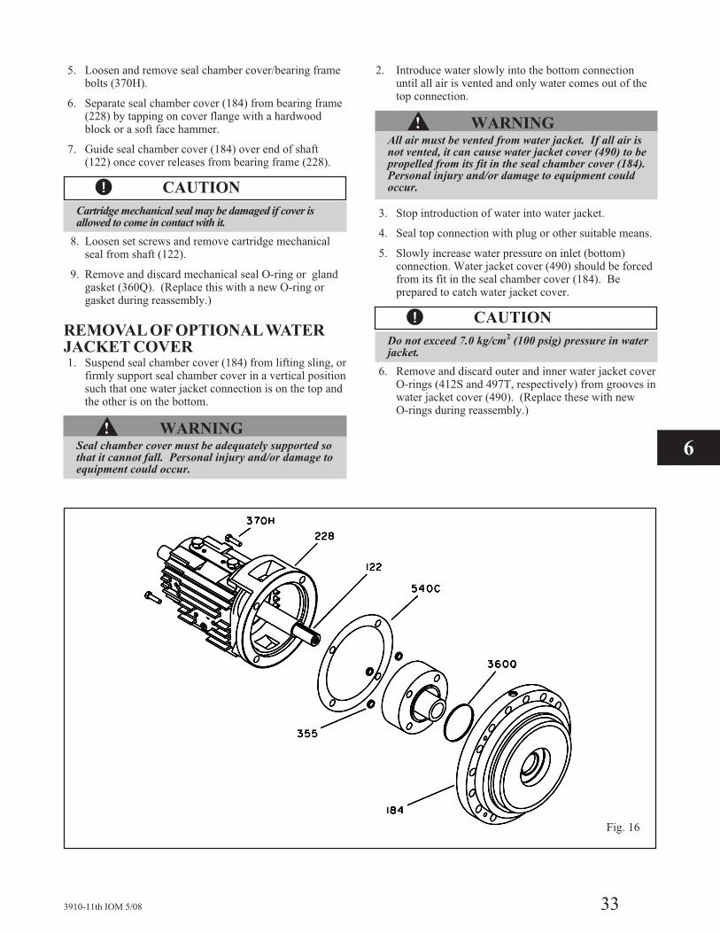
5. Loosen and remove seal chamber cover/bearing framebolts (370H).
6. Separate seal chamber cover (184) from bearing frame(228) by tapping on cover flange with a hardwoodblock or a soft face hammer.
7. Guide seal chamber cover (184) over end of shaft(122) once cover releases from bearing frame (228).
�! CAUTION
Cartridge mechanical seal may be damaged if cover isallowed to come in contact with it.
8. Loosen set screws and remove cartridge mechanicalseal from shaft (122).
9. Remove and discard mechanical seal O-ring or glandgasket (360Q). (Replace this with a new O-ring orgasket during reassembly.)
REMOVAL OF OPTIONAL WATERJACKET COVER1. Suspend seal chamber cover (184) from lifting sling, or
firmly support seal chamber cover in a vertical positionsuch that one water jacket connection is on the top andthe other is on the bottom.
�! WARNINGSeal chamber cover must be adequately supported sothat it cannot fall. Personal injury and/or damage toequipment could occur.
2. Introduce water slowly into the bottom connectionuntil all air is vented and only water comes out of thetop connection.
�! WARNINGAll air must be vented from water jacket. If all air isnot vented, it can cause water jacket cover (490) to bepropelled from its fit in the seal chamber cover (184).Personal injury and/or damage to equipment couldoccur.
3. Stop introduction of water into water jacket.
4. Seal top connection with plug or other suitable means.
5. Slowly increase water pressure on inlet (bottom)connection. Water jacket cover (490) should be forcedfrom its fit in the seal chamber cover (184). Beprepared to catch water jacket cover.
�! CAUTION
Do not exceed 7.0 kg/cm2
(100 psig) pressure in waterjacket.
6. Remove and discard outer and inner water jacket coverO-rings (412S and 497T, respectively) from grooves inwater jacket cover (490). (Replace these with newO-rings during reassembly.)
3910-11th IOM 5/08 33
Fig. 16
6

DISASSEMBLY OF STANDARDGREASE LUBRICATED POWER ENDThis section covers disassembly of standard ring oil oroptional purge oil mist lubricated power end. For powerends with optional features (pure oil mist lubrication,bearing cooling, etc.), refer to the appropriate section.
1. Loosen and remove thrust bearing end cover/bearingframe screws (370N).
2. Pry thrust bearing end cover (109A)/INPRO (123A)with O-ring (412, not shown) out of bearing frame(228). SA thrust bearing end cover is sealed to thebearing frame with a gasket (360A) (Fig. 17).
3. Remove and discard thrust bearing end cover shims(390C). Replace with new shims during reassembly.(Not applicable to pumps with SA bearing frame.)
4. Withdraw shaft/bearing assembly carefully frombearing frame (228).
� CAUTION
Do NOT remove bearings from shaft unlessthey are to be replaced.
5. Bend locking tang of thrust bearing lockwasher (382) fromnotch in bearing locknut (136) (Fig. 18).
NOTE: Save bearings for inspection.
6. Loosen and remove thrust bearing locknut (136) andlockwasher (382).
7. Press or pull duplex thrust bearing (112) from shaft(122).
8. Remove grease shelf (253) from shaft (122).
9. Press or pull radial bearing (168) from shaft (122).
NOTE: Save bearing for inspection.
10. Loosen and remove radial bearing end cover / bearingframe screws (370P) (Fig. 19). Omit this step on SApumps. Radial INPRO Oil Seal (123) is pressed inplace and sealed with an O-ring (Fig. 20).
11. Remove radial bearing end cover (119A)/ RadialINPRO (123) with gasket (360) or Radial INPRO(123) (SA pump only) from bearing frame (228) bytapping out of fit in frame.
34 3910-11th IOM 5/08
Fig. 17
Fig. 18

12. Remove and discard radial bearing end cover gasket(360). (Replace this with a new gasket duringreassembly.)
13. Press Radial and Thrust INPRO (123 & 123A) out ofradial (N/A on SA pumps) and Thrust End Covers(119A & 109A).
DISASSEMBLY OF OPTIONAL PUREOILMIST LUBRICATED POWER ENDPure oil mist lubricated power ends are disassembled in thesame manner as grease lubricated power ends. Greaseshelf (253) is not furnished with pure oil mist lubrication.Disregard any reference to this part.
DISASSEMBLY OF POWER ENDWITH OPTIONAL RADIAL HEATFLINGERThe radial heat flinger (123B) replaces the standard radialINPRO (123) and is removed in the same manner except 3set screws (222) need to be loosened (Fig. 21). Removeand discard frame / seal chamber cover thermal gasket(540C) (Fig. 16). (Replace this with a new gasket duringreassembly. Remainder of disassembly is the same asgrease lubrication.
DISASSEMBLY OF POWER ENDWITH OPTIONAL AIR COOLINGPACKAGE1. Loosen radial heat flinger set screw (222) (Fig. 21).
2. Loosen thrust fan set screw (222). SA pumps thrust fansits on coupling diameter.
3. Slide thrust fan (123E) off shaft (122).
4. Loosen and remove thrust bearing end cover/bearingframe screws (370N).
5. Remove thrust fan guard support (234D).
Remainder of disassembly is the same as steps 2-13 ofgrease lubrication section.
FINAL DISASSEMBLYRemove any remaining plugs and fittings.
3910-11th IOM 5/08 35
Fig. 19
Fig. 20
Fig. 21
6

INSPECTIONS
Model 3910 parts must be inspected to the followingcriteria before they are reassembled to ensure the pump willrun properly. Any part not meeting the required criteriashould be replaced.
NOTE: Clean parts to remove oil, grease or dirt.Protect machined surfaces against damage duringcleaning.
CASING (100)The casing should be inspected for excessive wear,corrosion or pitting. Areas most susceptible are indicatedby the arrows in Fig. 22. Casing should be repaired orreplaced if it exceeds the following criteria:
1. Localized wearing or grooving greater than 3.2 mm(1
8 in.) deep.
2. Pitting greater than 3.2 mm (18 in.) deep.
3. Irregularities in case gasket seat surface which couldhinder or prevent sealing.
IMPELLER (101)1. Inspect impeller vanes for damage. Replace if grooved
deeper than 1.6 mm (116 in.) or if worn evenly more
than 0.8 mm (132 in.). (Area “a” in Fig. 23.)
2. Inspect shrouds for damage. Replace if worn or bentmore than 0.8 mm (1
32 in.). (Area “b” in Fig. 23.)
3. Inspect leading and trailing edges of the vanes for pitting,and erosion or corrosion damage. Replace as in No. 1.(Area “c” in Fig. 23.)
4. Clean and check impeller bore diameter.
5. Check impeller balance. It should be rebalanced if itexceeds the criteria of ISO 1940 G1.0.
NOTE: Balancing impellers to ISO 1940 G1.0 requiresextremely accurate tooling and equipment and shouldnot be attempted unless such tooling and equipmentare available.
BALL BEARINGS (112, 168)1. Ball bearings should be inspected for contamination
and damage. The condition of the bearings willprovide useful information on operating conditions inthe bearing frame (228).
2. Lubricant condition and residue should be noted.
3. Bearing damage should be investigated to determine cause.If cause is not normal wear, it should be corrected beforepump is returned to service.
NOTE: It is good practice to replace all ball bearings thathave been removed from their shaft fits. Always replace ifthey are worn, loose or rough and noisy when rotated.Replacement bearings must be of proper size and type.
4. Replacement bearings must be the same as, orequivalent to, those listed in Table 3.
Table 4Model 3910 Bearings
Group
Radial (Inboard) Thrust(Outboard)Grease Oil Mist
SASX
MX, LAXLX
6210 C3Z6212 C3Z6213 C3Z6218 C3Z
6210 C36212 C36213 C36218 C3
7310 BEGAM7312 BEGAM7312 BEGAM7317 BEGAM
NOTE: Bearing numbers are based on SKF / MRCdesignations.
36 3910-11th IOM 5/08
Fig. 22
Fig. 23

SHAFT (122)1. Check bearing fits. If any are outside the tolerance
shown in Tables 5 or 5A, replace the shaft (Fig. 24).
2. Check shaft surface for damage, especially in areasindicated by arrows in Fig. 24. Replace if damagedbeyond reasonable repair.
3. Check shaft straightness. Use “V” blocks or balancerollers to support the shaft on bearing fit areas.Replace shaft if runout exceeds 0.03 mm (.001 in.)
NOTE: Do NOT use shaft centers for runout check asthey may have been damaged when removing bearingsor impeller.
3910-11th IOM 5/08 37
Fig. 24
Table 5Model 3910 Bearing Fits & Tolerances (SI Units)
According to ISO 286 (ANSI/ABMA Standard 7)
Location DescriptionGroup and Dimensions (mm)
SA SX MX, LA XLX
Radial(Inboard)
Shaft O.D.50.013 60.015 65.015 90.018
50.002 60.002 65.002 90.003
Interference0.002 0.002 0.002 0.003
0.025 0.030 0.030 0.038
Bearing I.D.49.988 59.985 64.985 89.980
50.000 60.000 65.000 90.000
Frame I.D.90.000 110.000 120.000 160.000
90.022 110.022 120.022 160.025
Clearance0.000 0.000 0.000 0.000
0.037 0.037 0.037 0.050
Bearing O.D.90.000 110.000 120.000 160.000
89.985 110.022 119.985 159.975
Thrust(Outboard)
Shaft O.D.50.013 60.015 60.015 85.018
50.002 60.002 60.002 85.003
Interference0.002 0.002 0.002 0.003
0.025 0.030 0.030 0.038
Bearing I.D.49.998 59.985 59.985 84.980
50.000 60.000 60.000 85.000
Frame I.D.110.000 130.000 130.000 180.000
110.022 130.025 130.025 180.025
Clearance0.000 0.000 0.000 0.000
0.037 0.043 0.043 0.050
Bearing O.D.110.000 130.000 130.000 180.000
109.985 129.982 129.982 179.975
6
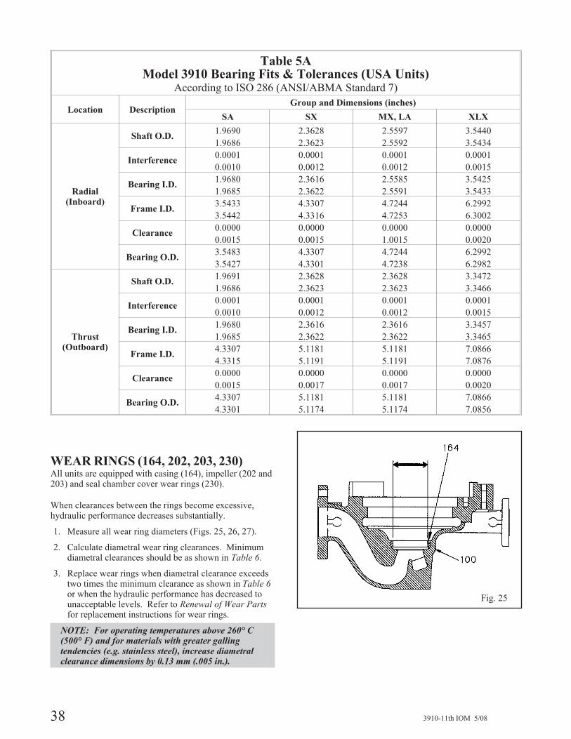
WEAR RINGS (164, 202, 203, 230)All units are equipped with casing (164), impeller (202 and203) and seal chamber cover wear rings (230).
When clearances between the rings become excessive,hydraulic performance decreases substantially.
1. Measure all wear ring diameters (Figs. 25, 26, 27).
2. Calculate diametral wear ring clearances. Minimumdiametral clearances should be as shown in Table 6.
3. Replace wear rings when diametral clearance exceedstwo times the minimum clearance as shown in Table 6or when the hydraulic performance has decreased tounacceptable levels. Refer to Renewal of Wear Partsfor replacement instructions for wear rings.
NOTE: For operating temperatures above 260° C(500° F) and for materials with greater gallingtendencies (e.g. stainless steel), increase diametralclearance dimensions by 0.13 mm (.005 in.).
38 3910-11th IOM 5/08
Table 5AModel 3910 Bearing Fits & Tolerances (USA Units)
According to ISO 286 (ANSI/ABMA Standard 7)
Location DescriptionGroup and Dimensions (inches)
SA SX MX, LA XLX
Radial(Inboard)
Shaft O.D.1.9690 2.3628 2.5597 3.5440
1.9686 2.3623 2.5592 3.5434
Interference0.0001 0.0001 0.0001 0.0001
0.0010 0.0012 0.0012 0.0015
Bearing I.D.1.9680 2.3616 2.5585 3.5425
1.9685 2.3622 2.5591 3.5433
Frame I.D.3.5433 4.3307 4.7244 6.2992
3.5442 4.3316 4.7253 6.3002
Clearance0.0000 0.0000 0.0000 0.0000
0.0015 0.0015 1.0015 0.0020
Bearing O.D.3.5483 4.3307 4.7244 6.2992
3.5427 4.3301 4.7238 6.2982
Thrust(Outboard)
Shaft O.D.1.9691 2.3628 2.3628 3.3472
1.9686 2.3623 2.3623 3.3466
Interference0.0001 0.0001 0.0001 0.0001
0.0010 0.0012 0.0012 0.0015
Bearing I.D.1.9680 2.3616 2.3616 3.3457
1.9685 2.3622 2.3622 3.3465
Frame I.D.4.3307 5.1181 5.1181 7.0866
4.3315 5.1191 5.1191 7.0876
Clearance0.0000 0.0000 0.0000 0.0000
0.0015 0.0017 0.0017 0.0020
Bearing O.D.4.3307 5.1181 5.1181 7.0866
4.3301 5.1174 5.1174 7.0856
Fig. 25

Table 6Minimum Running Clearances
Diameter ofImpeller
Wear Ring
MinimumDiametralClearance
mm in. mm in.
<50 <2.000 0.25 0.010
To to 64.99 2.000 to 2.4999 0.28 0.011
65 to 79.99 2.500 to 2.999 0.30 0.012
80 to 89.99 3.000 to 3.499 0.33 0.013
90 to 99.99 3.500 to 3.999 0.35 0.014
100 to 114.99 4.000 to 4.499 0.38 0.015
115 to 124.99 4.500 to 4.999 0.40 0.016
125 to 149.99 5.000 to 5.999 0.43 0.017
150 to 174.99 6.000 to 6.999 0.45 0.018
175 to 199.99 7.000 to 7.999 0.48 0.019
200 to 224.99 8.000 to 8.999 0.50 0.020
225 to 249.99 9.000 to 9.999 0.53 0.021
250 to 274.99 10.000 to 10.999 0.55 0.022
275 to 299.99 10.000 to 11.999 0.58 0.023
300 to 324.99 12.000 to 12.999 0.60 0.024
SEAL CHAMBER COVER (184)Seal chamber cover is available in two versions: one(optional) has a cooling chamber and water jacket cover(490) and the other (standard) does not. The (optional)cooled version is used when elevated pumpagetemperatures are present.
1. Ensure all gasket/O-ring sealing surfaces are clean andhave no damage that would hinder or prevent sealing(Fig. 28).
2. Ensure all cooling (where applicable), flush and drainpassages are clear.
3. Inspect other surfaces for damage. Replace if worn,damaged or corroded more than 3.2 mm (1
8 in.) deep.
4. Measure inside diameter of seal chamber coverbushing (125). If the diametral clearance between itand the impeller hub (101) exceeds 1.20 mm (.047 in.),one or both parts should be replaced. Refer toRenewal of Wear Parts for replacement instructionsfor seal chamber cover bushing.
3910-11th IOM 5/08 39
Fig. 26
Fig. 27
Fig. 28
6

BEARING FRAME (228)1. Visually inspect bearing frame for damage and cracks.
2. Check frame inside surfaces for rust, scale or debris.Remove all loose and foreign material (Fig. 29).
3. Make sure all lubrication passages are clear.
4. Check bearing bores. If any are outside the tolerancein Table 6, replace the bearing frame.
CARTRIDGE MECHANICAL SEALRefer to mechanial seal manufacturer’s instructions forassistance.
Cartridge type mechanical seals should be serviced by sealmanufacturer.
COUPLING GUARD1. Inspect guard for corrosion or other defects.
2. Replace guard or repair.
�! WARNINGTo avoid physical injury, coupling guard must beinstalled and must be maintained in first-classcondition.
GASKETS, O-RINGS, SHIMS, ANDSEATS
NOTE: Spiral wound gaskets should not be reused.
1. Replace all gaskets, O-rings and shims at eachoverhaul / disassembly.
2. Inspect seats. They must be smooth and free ofphysical defects. Skin cut seats in lathe as necessary,maintaining dimensional relationships with othersurfaces. Replace parts if seats are defective beyondreasonable repair.
GENERALAll other parts should be inspected and repaired orreplaced, as appropriate, if inspection indicates continueduse would be harmful to satisfactory and safe pumpoperation.
Inspection must include, but not be limited to, thefollowing:
• Bearing End Covers (109A) and (119A)
• INPROS (123) and (123A)
• Radial Heat Flinger (123B)*
• Thrust Fan (123E)*
• Bearing Locknut (136)
• Impeller Key (178) and Coupling Key
• Impeller Nut (304)
• Bearing Lockwasher (382)
• Water Jacket Cover (490)*
• All Nuts, Bolts and Screws
* If supplied.
40 3910-11th IOM 5/08
Fig. 29

RENEWAL OF WEAR PARTS
REPLACEMENT OF SEALCHAMBER COVER BUSHINGSeal chamber cover bushing (125) is held in place by apress fit and locked by three set screws.
Removal of Bushing (125)
1. Remove set screws.
2. Press bushing (125) out of fit toward bearing frameside of seal chamber cover (184) bore (Fig. 30).
Installation of Bushing (125)
1. Clean bushing fit in seal chamber cover (184)thoroughly.
2. Chill new bushing (125) using dry ice or other suitablechilling substance, and install bushing into fit of cover(184). Be prepared to tap the bushing in place with ahardwood block or soft faced hammer (Fig. 31).
�! WARNINGDry ice and other chilling substances can cause physicalinjury. Contact supplier for information and advice forproper handling precautions and procedures.
3. Locate, drill and tap three new set screw holes onimpeller side of cover (184) equally spaced betweenoriginal set screw holes.
4. Install set screws and upset threads.
REPLACEMENT OF WEAR RINGSCasing (164), impeller (202 and 203) and seal chambercover wear rings (230) are held in place by a press fit andthree set screws (222E and 320).
Removal of Wear Rings (164, 202, 203, 230)
1. Remove set screws (222E and 320).
2. Remove wear rings from casing (100), impeller (101),and seal chamber cover (184) using suitable pry orpuller to force rings from fits.
Rings may also be machined for removal.
�! CAUTION
Excessive machining can damage ring fits and renderparts unusable.
Installation of Wear Rings (164, 202, 203, 230)
1. Clean wear ring seats thoroughly, insuring they aresmooth and free of scratches.
2. Heat new impeller wear rings (202 and 203) to 82° -93° C (180° - 200° F) using a uniform method forheating (e.g. - oven) and place on impeller (101) wearring seats (Fig. 32).
�! CAUTION
Use insulated gloves to handle rings. Ringswill be hotand can cause physical injury.
3910-11th IOM 5/08 41
Fig. 30
Fig. 31
6
Fig. 32

3. Chill new casing wear ring (164) using dry ice or othersuitable chilling substance, and install ring into fit ofcasing (100). Be prepared to tap the ring in place witha hard wood block or soft faced hammer (Fig. 33).
�! WARNINGDry ice and other chilling substances can cause physicalinjury. Contact supplier for information and advice forproper handling precautions and procedures.
4. Chill new seal chamber cover wear ring (230), usingdry ice or other suitable chilling substance, and installring into fit of cover (184). Be prepared to tap the ringin place with a hardwood block or soft faced hammer(Fig. 34).
�! WARNINGDry ice and other chilling substances can cause physicalinjury. Contact supplier for information and advice forproper handling precautions and procedures.
5. Locate, drill and tap three new set screw holes equallyspaced between the original holes in each new ring andring seat area.
6. Install set screws (222E and 320) and upset threads.
� The impeller and wear ring clearance settingprocedures must be followed. Improperly setting theclearance or not following any of the properprocedures can result in sparks, unexpected heatgeneration and equipment damage.
7. Check casing wear ring (164) runout / distortion bymeasuring bore at each set screw location with insidemicrometers or vernier calipers (Fig. 35). Any distortionin excess of 0.08 mm (.003 in.) should be corrected bymachining prior to trimming new impeller wear rings(202 and 203).
8. Measure bore of casing wear ring (164) to establish therequired impeller wear ring (202) diameter to providethe recommended running clearances as indicated inTable 6 and subsequent note.
9. Repeat steps 7 and 8 for the seal chamber wear ring(230).
10. Turn impeller wear rings (202 and 203) to size aftermounting on impeller (101).
NOTE A: All replacement impeller wear rings, exceptthose hard faced, are supplied 0.51 mm (.020 in.) to0.75 mm (.030 in.) oversize.
NOTE B: Spare hard faced impeller wear rings arenot supplied oversize but are supplied to pre-established proper running clearances when bothimpeller and casing wear rings are renewed.
42 3910-11th IOM 5/08
Fig. 33
Fig. 34
Fig. 35

�! CAUTION
For runout checks, firmly support bearing frameassembly in horizontal position, as shown in Fig. 36.
11. Check impeller wear ring runout in the followingmanner:
a. Install impeller key (178) on shaft (122) of
assembled bearing frame from which the seal
chamber cover (184) has been removed, and on
which the runouts have been determined to be
within the specifications established in
Reassembly section. Key should be at top (12
o’clock) position for installation of impeller (101).
b. Install impeller (101) on shaft (122).
�! CAUTION
When handling the impeller, wear heavy work gloves toprevent cutting hands on sharp edges.
c. Secure impeller (101) firmly with impeller nut
(304).
NOTE: Impeller nut has LEFT HAND threads.
d. Mount dial indicator as shown in Fig. 37.
e. Rotate shaft (122) so indicator rides along the
casing side impeller wear ring (202) surface for
360 degrees.
f. Repeat steps d and e for seal chamber cover side
wear ring (203).
If impeller wear ring (203 and 203) runout is in excess of0.13 mm (.005 in.):
a. Check for distortion at set screw areas.
b. Check shaft (122) runout and all mating surfaces
of shaft and impeller (101) hub for perpendicu-
larity.
c. True up all surfaces found damaged and recheck
impeller wear ring (202 and 203) runout.
3910-11th IOM 5/08 43
Fig. 36
Fig. 37
6
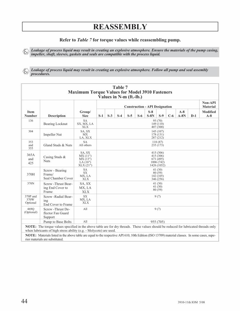
REASSEMBLY
Refer to Table 7 for torque values while reassembling pump.
� Leakage of process liquid may result in creating an explosive atmosphere. Ensure the materials of the pump casing,impeller, shaft, sleeves, gaskets and seals are compatible with the process liquid.
� Leakage of process liquid may result in creating an explosive atmosphere. Follow all pump and seal assemblyprocedures.
44 3910-11th IOM 5/08
Table 7Maximum Torque Values for Model 3910 Fasteners
Values in N-m (ft.-lb.)
ItemNumber Description
Group/Size
Construction - API DesignationNon-APIMaterial
S-1 S-3 S-4 S-5 S-6S-8
S-8N S-9 C-6A-8
A-8N D-1Modified
A-8
136Bearing Locknut
SASX, MX, LA
XLX
95 (70)149 (110)407 (300)
304Impeller Nut
SA, SXMX
LA, XLX
145 (107)178 (131)287 (212)
353and355
Gland Studs & NutsSA
All others118 (87)
235 (173)
365A
and
425
Casing Studs &Nuts
SA, SXMX (11")MX (13")LA (16")
XLX (21")
415 (306)415 (306)671 (495)
1006 (742)1426 (1052)
370HScrew - BearingFrame/Seal Chamber Cover
SASX
MX, LAXLX
41 (30)80 (59)
142 (105)346 (256)
370N Screw -Thrust Bear-ing End Cover toFrame
SA, SX
MX, LA
XLX
41 (30)41 (30)80 (59)
370P and370W
Optional
Screw -Radial Bear-ingEnd Cover to Frame
SXMX, LA
XLX
9 (7)
469Q(Optional)
Screw -Thrust De-flector Fan GuardSupport
All 9 (7)
Pump to Base Bolts All 955 (705)
NOTE: The torque values specified in the above table are for dry threads. These values should be reduced for lubricated threads onlywhen lubricants of high stress ability (e.g. - Molycote) are used.
NOTE: Materials listed in the above table are equal to the respective API 610, 10th Edition (ISO 13709) material classes. In some cases, supe-rior materials are substituted.

3910-11th IOM 5/08 45
ASSEMBLY OF STANDARD GREASELUBRICATED POWER END
This section covers assembly of standard grease lubricatedpower end. For power ends with optional features (pure oilmist lubrication, bearing cooling, etc.), refer to theappropriate section.
�! WARNING
Pump components are heavy. Proper methods of liftingand securing must be employed to avoid physical injuryand/or equipment damage.
NOTE: Make sure that all parts and threads are cleanand that all directions under Inspections have beenfollowed.
� Leakage of process liquid may result in creating anexplosive atmosphere. Follow all pump and sealassembly procedures.
1. Install radial (inboard) bearing (168) on shaft (122)
with shield facing shaft shoulder (Fig. 38).
NOTE: There are several methods used to install bear-ings. The recommended method is to use an inductionheater that heats as well as demagnetizes the bearings.
� CAUTION
Use insulated gloves when using a bearing heater.Bearing will get hot and can cause physical injury.
2. Install grease shelf (253) on shaft (122).
3. Install thrust (outboard) bearings (112) on shaft (122).
� CAUTION
The Model 3910 uses duplex bearings mounted back-to-back. Make sure orientation of the bearings is correct.
NOTE: There are several methods used to installbearings. The recommended method is to use aninduction heater that heats as well as demagnetizes thebearings.
�! CAUTION
Use insulated gloves when using a bearing heater.Bearings will get hot and can cause physical injury.
4. Place bearing lockwasher (382) on shaft (122). Place
tang of lockwasher in keyway of shaft.
5. Thread bearing locknut (136) onto shaft (122). After
bearings and shaft have cooled to ambient temperature,
tighten locknut to torque value shown in Table 7.
6. Bend any tang of bearing lockwasher (382) into a slot of
locknut (136).
Fig. 38 6

NOTE: Coat internal surfaces of bearings withlubricant to be used in service.
7. Press radial INPRO (123) into radial end cover (119A).
Ensure expulsion port is at 6 o'clock position and is
properly seated. Install radial bearing end cover (119A),
and new end cover gasket (360) on bearing frame (228)
(Fig. 39). For SA pumps, press radial INPRO (123) into
bearing frame 228. Ensure expulsion port is at 6 o'clock
position and is properly seated (Fig. 40).
8. For SX, MX, LA, and XLX pumps, install and tighten
radial end cover bolt/bearing frame screws (370P)
evenly to the torque values shown in Table 7.
9. Coat outer races of bearings (112) and (168) with
compatible oil.
10. Coat internal bearing surfaces of bearing frame (228)
with compatible oil.
11. Carefully guide shaft/bearing assembly into bearing
frame (228) until thrust bearing (112) is seated against
shoulder of frame (Fig. 41).
NOTE: Do not force assembly together.
12. Check shaft (122) for free turning. If rubbing or
binding is detected, determine cause and correct.
13. For SX, MX, LA, and XLX pumps, install three (3)
thrust bearing end cover shims (390C) on the thrust
bearing end cover (109A) and align holes. For SA
pumps, install three (3) thrust bearing end cover
gaskets (360A) on the bearing end cover (109A).
Align the gasket to the end cover so that the openings
in the gaskets align with the oil grooves on the end
cover (Fig. 42).
�! CAUTION
Failure to align gasket with oil grooves will result inbearing failure from lack of lubrication.
46 3910-11th IOM 5/08
Fig. 39
Fig. 40
Fig. 41
Fig. 42

14. Install thrust bearing end cover (109A) over shaft
(122) and onto bearing frame (228). For SA pumps,
install thrust cover with the words “Top oil mist” on
top.
15. Install and tighten thrust bearing end cover/bearing
frame screws (370N) evenly to torque valves shown in
Table 7.
�! CAUTION
Do not over tighten thrust bearing end cover/ bearingframe screws.
16. Determine axial end play as follows:
a. Mount dial indicator as shown in Fig. 43.
b. Apply axial force to impeller end of shaft (122)and firmly seat thrust bearing (112) againstshoulder in bearing frame (228).
c. Apply axial force in opposite direction and firmlyseat thrust bearing (112) against thrust bearing endcover (109A).
d. Repeat steps b and c several times and record totaltravel (end play) of rotating element.
e. Total travel (end play) must fall in the range of0.025 to 0.125 mm (0.001 to 0.005 inches).
17. The axial end play is achieved by adding or removing
end cover gaskets (360C) for SA pumps or end cover
shims (390C) between the thrust bearing end cover
(109A) and the bearing frame (228). Add
gaskets/shims if no axial end play is present.
18. Repeat steps 13 - 16. Total travel (end play) should
fall in the range of 0.025 - 0.125 mm
(.001 - .005 in.). If the measured total travel falls
outside this range, remove or add the appropriate
quantity of individual shims to obtain the proper total
travel. For SA pumps, skip steps 19 through 22.
19. Remove thrust bearing end cover (109A).
20. Press INPRO (123A) into thrust bearing end cover
(109A). Ensure expulsion port is at 6 o'clock position
and is properly seated.
21. Install O-ring (412, not shown) into groove in thrust
bearing end cover (109A) (N/A on SA pumps).
22. Lubricate O-ring (412) with a suitable lubricant.
23. Install thrust bearing end cover (109A) with O-ring
(412) over shaft (122) and into bore of bearing frame
(228). Ensure that O-ring is not damaged while
entering bore in frame.
24. Install and tighten thrust bearing end cover/ bearing
frame screws (370N) evenly to torque values shown in
Table 7.
� CAUTION
Do not over tighten thrust bearing end cover/ bearingframe screws.
25. Check shaft (122) for free turning. If rubbing or
excessive drag is detected, determine cause and
correct.
� CAUTION
For runout checks, firmly support bearing frameassembly in horizontal position, as shown in Fig. 36.
26. Check shaft (122) impeller fit runout in the following
manner:
a. Mount dial indicator on bearing frame (228) asshown in Fig. 44.
b. Rotate shaft (122) through maximum arc from oneside of keyway to the other. If total indicatorreading is greater than 0.050 mm (.002 in.),determine cause and correct.
� CAUTION
Avoid turning shaft so that dial indicator contactskeyway. Readings will be incorrect and damage to dialindicator could result.
3910-11th IOM 5/08 47
Fig. 43
Fig. 44
6

27. Check shaft (122) seal fit runout in the following
manner:
a. Mount dial indicator as shown in Fig. 45.
b. Rotate shaft (122) so indicator rides along shaftsurface for 360 degrees. If total indicator readingis greater than 0.050 mm (.002 in), determinecause and correct.
28. Check bearing frame (228) face runout in the
following manner:
a. Mount dial indicator on shaft (122) as shown inFig. 46.
b. Rotate shaft (122) so indicator rides along thebearing frame (228) face for 360 degrees. If totalindicator reading is greater than 0.10 mm (.004 in),disassemble and determine cause.
29. Check bearing frame (228) lock runout in the
following manner:
a. Mount dial indicator on shaft (122) as shown inFig. 47.
b. Rotate shaft (122) so indicator rides along thebearing frame (228) lock for 360 degrees. If totalindicator reading is greater than 0.10 mm (.004 in.),disassemble and determine cause.
30. Install and tighten any plugs and/or fittings removed
during disassembly.
ASSEMBLY OF OPTIONAL PUREOIL MIST LUBRICATED POWEREND
Pure oil mist lubricated power ends are assembled in the samemanner as grease lubricated power ends. Grease shelf (253) isnot furnished with pure oil mist lubrication. Any reference tothis part may be ignored.
ASSEMBLY OF POWER END WITHOPTIONAL RADIAL HEAT FLINGER
The radial heat flinger (123B) replaces the standard radialINPRO (123) and is installed in the same manner exceptthree set screws need to be tightened. Remainder ofassembly is the same as ring oil lubrication. During theassembly of the bearing frame (228) and seal chambercover (184), install bearing frame / seal chamber covergasket (540C) into recess on bearing frame (228) and alignholes (Fig. 57).
ASSEMBLY OF POWER END WITHOPTIONAL AIR COOLINGPACKAGE
Assemble power end as described in steps 1-23 of ring oillubrication section. Note that in step 7, radial heat flinger(123B) replaces the standard radial INPRO (123).
24a. Position thrust fan guard support (234D) on thrust
bearing end cover (109A).
48 3910-11th IOM 5/08
Fig. 46
Fig. 45
Fig. 47

24b. Install and tighten thrust bearing end cover/ bearing
frame screws (370N) evenly to torque values shown
in Table 7.
�! CAUTION
Do not over tighten thrust bearing end cover/ bearingframe screws.
24c. Install thrust fan (123E) over shaft (122).
24d. Position thrust fan (123E) approximately 0.8 mm
(.030 in.) from thrust INPRO (123A) and tighten
deflector fan set screw (222) firmly. On SA, pumps
butt fan against coupling diameter shoulder.
24e. Tighten heat flinger set screws (222) firmly.
Complete assembly of power end as described in steps 25 -30 of grease oil lubrication section. During the assembly ofthe bearing frame (228) and seal chamber cover (184),install bearing frame / seal chamber cover gasket (540C)into recess on bearing frame (228) and align holes(Fig. 57).
INSTALLATION OF OPTIONALWATER JACKET COVER
1. Install outer and inner water jacket cover O-rings
(412S and 497T, respectively) into grooves in water
jacket cover (490) (Fig. 49).
2. Lubricate sealing surfaces in seal chamber cover (184)
and O-rings (412S and 497T) with suitable lubricant.
3. Insert water jacket cover (490) with O-rings (412S and
497T) into fit in seal chamber cover (184). Ensure that
water jacket cover enters uniformly and that O-rings
are not damaged.
3910-11th IOM 5/08 49
Fig. 48
Fig. 49
6

PRELIMINARY INSTALLATION OFSEAL CHAMBER COVER
1. Install eyebolt in tapped hole provided in seal chamber
cover (184) (Fig. 50).
2. Rig sling to eyebolt and to overhead lifting device.
3. Lift seal chamber cover (184) and position to align
with shaft (122).
4. Install seal chamber cover (184) on bearing frame
assembly by guiding cover carefully over shaft (122)
and into bearing frame (228) lock.
5. Install seal chamber cover/bearing frame bolts (370H)
and tighten evenly using alternating pattern. Torque
bolts to values shown in Table 7.
� CAUTION
For runout checks, firmly support bearing frameassembly in horizontal position, as shown in Fig. 36.
6. Check seal chamber cover (184) face runout in the
following manner:
a. Mount dial indicator on shaft (122) as shown inFig. 51.
b. Rotate shaft (122) so indicator rides along the sealchamber cover (184) gasket face for 360 degrees. Iftotal indicator reading is greater than 0.13 mm (.005in.), determine cause and correct.
7. Check seal chamber cover (184) lock runout in the
following manner:
a. Mount dial indicator on shaft (122) as shown inFig. 52.
b. Rotate shaft (122) so indicator rides along the sealchamber cover (184) lock for 360 degrees. If totalindicator reading is greater than 0.13 mm (.005 in.),determine cause and correct.
NOTE: If two dial indicators are available, steps 6and 7 may be performed simultaneously.
� The impeller and wear ring clearance settingprocedures must be followed. Improperly setting theclearance or not following any of the properprocedures can result in sparks, unexpected heatgeneration, and equipment damage.
50 3910-11th IOM 5/08
Fig. 50
Fig. 51
Fig. 52

8. Check seal chamber cover wear ring (230) runout in
the following manner:
a. Mount dial indicator on shaft (122) as shown inFig. 53.
b. Rotate shaft (122) so indicator rides on sealchamber cover wear ring (230) surface for 360degrees. If total indicator reading exceeds 0.15mm (.006 in.), determine cause and correct.
9. Check seal chamber face runout in the following
manner:
a. Mount dial indicator on shaft (122) as shown inFig. 54.
b. Rotate shaft (122) so indicator rides along the sealchamber face for 360 degrees. If total indicator readingis greater than the values shown in Table 7, determinecause and correct.
Table 8Maximum Allowable Seal Chamber Face
Runout
Group Maximum Allowable Total Indicator Reading
SA 0.045 mm (0.0018 in.)
SX 0.05 mm. (.002 in.)
MX, LA 0.06 mm. (.0024 in.)
XLX 0.07 mm. (.0028 in.)
10. Check seal chamber lock (register) runout in the
following manner:
a. Mount dial indicator on shaft (122) or shaft sleeve(126) as shown in Fig. 55.
b. Rotate shaft (122) so indicator rides along the sealchamber lock (register) for 360 degrees. If totalindicator reading is greater than 0.125 mm (.005in.), determine cause and correct.
11. Install impeller key (178) in keyway of shaft (122).
Key should be at top (12 o’clock) position for
installation of impeller (101).
12. Install impeller (101) on shaft (122).
� CAUTION
When handling impeller, wear heavy work gloves toprevent cutting hands on sharp edges.
NOTE: Anti-galling compound should be applied tothe impeller bore to aid in assembly and disassembly.
13. Install impeller nut (304) and tighten firmly.
NOTE: Impeller nut has LEFT HAND threads.
� CAUTION
� The impeller and wear ring clearance settingprocedures must be followed. Improperly setting theclearance or not following any of the properprocedures can result in sparks, unexpected heatgeneration and equipment damage.
3910-11th IOM 5/08 51
Fig. 54
Fig. 53
Fig. 55
6

14. Check impeller (101) impeller wear ring (202) runout
in the following manner:
a. Mount dial indicator as shown in Fig. 63.
b. Rotate shaft (122) so indicator rides along wearring (202) surface for 360 degrees. If totalindicator reading is greater than 0.13 mm (.005in.), determine cause and correct.
INSTALLATION OF CARTRIDGETYPE MECHANICAL SEAL ANDSEAL CHAMBER COVER
NOTE: Refer to mechanical seal manufacturer’s draw-ings and instructions for assistance during installation ofmechanical seal.
1. Loosen and remove impeller nut (304).
NOTE: Impeller nut has LEFT HAND threads.
2. Remove impeller (101), impeller key (178), and seal
chamber cover (184) as described in disassembly.
3. Lubricate all O-rings with suitable lubricant, unless seal
manufacturer’s instructions indicate otherwise.
4. Slide cartridge seal assembly (rotary, stationary, gland,
gland gasket and sleeve) onto shaft (122) (Fig. 57).
NOTE: Ensure that mechanical seal gland pipingconnections are properly oriented.
5. Rig sling to eyebolt and to overhead lifting device.
6. Lift seal chamber cover (184) and position to align
with shaft (122).
7. Install seal chamber cover (184) on power end by guiding
cover carefully over cartridge seal rotary and ensuring
that gland studs (353) smoothly enter holes in cartridge
seal gland and that cover pilots into bearing frame (228)
lock.
� CAUTION
Mechanical seal parts may be damaged if they oradjacent parts are handled improperly.
8. Install seal chamber cover/bearing frame bolts (370H)
and tighten using alternating pattern. Torque bolts to
values shown in Table 7.
9. Install gland stud nuts (355) and tighten evenly to
torque values shown in Table 7.
10. Tighten set screws in locking collar.
11. Disengage spacer ring or clips.
12. Check for free turning. If rubbing or excessive drag is
detected, determine cause and correct.
INSTALLATION OF IMPELLER
NOTE: It is desirable to repeat runout checks on sealchamber cover face, lock and wear ring surfaces aspreviously described in “Preliminary Installation of SealChamber Cover”.
1. Install impeller key (178) in keyway of shaft (122).
Key should be at top (12 o’clock) position for
installation of impeller (101).
� CAUTION
When handling impeller, wear heavy work gloves toprevent cutting hands on sharp edges.
52 3910-11th IOM 5/08
Fig. 56
Fig. 57

2. Install impeller (101) on shaft (122).
NOTE: Anti-galling compound should be applied tothe impeller bore to aid in assembly and disassembly.
3. Install impeller nut (304) and tighten to torque values
shown in Table 7.
NOTE: Impeller nut has LEFT HAND threads.
4. Tighten the set screw (198A) in the end of the impeller
nut (304).
5. Check for free turning. If rubbing or excessive drag is
detected, determine cause and correct.
NOTE: It is desirable to repeat runout check onimpeller wear ring surface as previously described in“Replacement of Wear Rings.”
INSTALLATION OF COUPLING HUB
Install key and pump half coupling hub on shaft (122) untilhub is flush with the scribe mark determined duringdisassembly (Fig. 58). Refer to coupling manufacturer’sinstructions for assistance.
INSTALLATION OF BACKPULL-OUT ASSEMBLY IN CASING
1. Install new casing gasket (351) on gasket surface of
casing (100).
NOTE: Anti-galling compound may be applied to thecasing fits to aid in assembly and disassembly.
2. Replace back pull-out assembly in casing (100) using
Goulds back pull-out device or other suitable means.
Refer to instructions in Appendix III.
3. Lower back pull-out assembly into proper position in
casing (100) by loosening jacking bolts (418) evenly.
NOTE: Ensure that casing gasket is not damaged.
4. Install casing stud nuts (425).
5. Inspect gap between seal chamber cover (184) and casing
(100) and adjust casing stud nuts (425) as necessary to
make gap uniform.
6. Tighten casing stud nuts (425) uniformly, using
alternating pattern, until seal chamber cover (184) is in
metal-to-metal contact with the casing (100). Tighten
each nut to torque value shown in Table 7.
7. Check for free turning. If rubbing or excessive drag is
detected, determine cause and correct.
ADDITIONAL ASSEMBLY
1. Replace coupling spacer, coupling guard and auxiliary
piping, tubing, and equipment that were removed
during preparation for disassembly.
2. Lubricate bearings as described in the Preventive
Maintenance section.
POST ASSEMBLY CHECKS
� All checks and procedures listed under Safety,Installation, Operation and PreventiveMaintenance sections must be followed.
� Rotate shaft by hand to ensure it rotates smoothly andthere is no rubbing which could lead to excess heatgeneration and or sparks.
3910-11th IOM 5/08 53
Fig. 58
6

ASSEMBLY TROUBLESHOOTING
54 3910-11th IOM 5/08
Symptom Probable Cause Remedy
Excessive shaft end play.
Bearing internal clearance too great. Replace bearings with correct type.
Excessive thrust bearing end cover shim packthickness.
Remove individual shims to obtain properthickness.
Thrust bearing end cover loose. Tighten screws.
Excessive shaft runout. Shaft bent. Replace.
Excessive bearing frame flangerunout.
Shaft bent. Replace.
Bearing frame flange distorted. Replace.
Excessive seal chamber coverrunout.
Seal chamber cover not properly seated on frame. Replace or remachine.
Corrosion or wear. Replace or remachine.
Excessive impeller wear ringrunout.
Bent shaft. Replace.
Improper machining of wear ring. Replace or remachine.

3910-11th IOM 5/08 55
THIS PAGE LEFT BLANK INTENTIONALLY
6

56 3910-11th IOM 5/08
PARTS LIST WITH STANDARD MATERIALS OF CONSTRUCTIONMaterials shown are typical. Refer to order documentation for actual materials furnished.
Item Part Name
Qtyper
Pump
Construction - API Designation
S-4 S-6 S-8 C-6 A-8
100 Casing 1 1212 1234 1296
101 Impeller 1 1212 1222 1265 1222 1265
109A Thrust Bearing End Cover 1 1212
112 Ball Bearing, Thrust 1 pair Steel
119A Radial Bearing End Cover 1 2210
122 Shaft 1 2238 2256 2244 2256
123 Deflector, Radial 1 1618
123A. Deflector, Thrust 1 1618
123B Deflector, Fan, Radial 1 1425
123C Deflector, Fan Thrust 1 1425
125 Throat Bushing, Seal Chamber 1 1001 2244 2256 2244 2256
136 Locknut, bearing 1 Steel
164 Wear Ring, Casing 1 1001 1232 1265 1232 1265
168 Ball Bearing, Radial 1 Steel
178 Key, Impeller 1 2229 2224 2229
184 Seal Chamber Cover 1 1212 1234 1296
198A Set Screw, Impeller Nut 1 2229
202 Wear Ring, Impeller 1 1001 1299 1071 1299 1071
203 Wear Ring, Impeller 1 1001 1299 1071 1299 1071
222 Set Screw, deflector 2 2229
222E Set Screw, stationary wear rings 6 2229
228 Bearing Frame 1 1212
230 Wear Ring, Seal Chamber Cover 1 1001 1232 1265 1232 1265
234 Deflector Fan Guard 1 3201
234D Support, Deflector Fan Guard 1 3201
240 Motor Support (Casing Mount) 1 3201
253 Grease Shelf 1 3201
304 Impeller Nut 1 2210 2229
320 Set Screw, Impeller Wear Ring 6 2229
340 Motor Support (Frame Mount) 1 3201
351 Gasket, Casing 1 Spiral Wound 316 Stainless Steel
353 Stud, Gland 4 2239
355 Nut, Gland Stud 4 2285
356A Stud, Casing Var. 2239
360 Gasket, Radial Bearing End Cover 1 Vellumoid
360A Gastket, Thrust Bearing End Cover 3 Vellumoid
370H Screw, Bearing Frame/ Seal Chamber Cover 4 2210
370N Screw, Thrust Bearing End Cover 5 2210
370P Screw, Radial Bearing End Cover 5 2210
382 Lockwasher, Bearing 1 Steel
390C Shim Pack, Thrust Bearing End Cover 1 304SS
408A Plug, Oil Drain 1 Steel with magnetic insert
412 O-ring, Thrust Bearing End Cover 1 Buna N
418 Bolt, Jacking 4 2210
425 Nut, Casing Stud Var. 2239
469P Retainer, Oil Ring 2 2285
497F O-ring, Thrust Deflector 1 Buna N
497H O-ring, Radial Deflector 1 Buna N
497S O-ring, Radial End Cover 1 Buna N
540C Gasket, Frame/Seal Chamber Cover 1 Aramid Fiber

3910-11th IOM 5/08 57
Materials Cross Reference Chart
MaterialGoulds PumpsMaterial Code
ASTMMaterial Designation Other
Cast Iron 1000 A48 Class 25
Cast Iron 1001 A48 Class 20
Nitronic 60 1071 A743 Gr. CF10SMnN
Carbon Steel 1212 A216 WCB
12% Chrome Steel 1222 A743 Gr. CA6NM
12% Chrome Steel 1232 A743 Gr. CA15
12% Chrome Steel 1234 A487 Gr. CA6MN Class A
316L Stainless Steel 1265 A743 Gr. CF3M
316L Stainless Steel 1296 A351 Gr. CF3M
12% Chrome Steel 1299 A743 Gr. CA15
Aluminum 1425 SC64D UNS A03190
Bismuth Bronze 1618 B505 CDA 89320
Steel 2210 A108 Gr. 1211 UNS G12110
316 Stainless Steel 2229 A276 Type 316
4140 Steel 2238 A434 Gr. 4140 Class BD
410 Stainless Steel 2244 A276 Type 410 UNS S41000
316L Stainless Steel 2256 A276 Type 316L UNS S31603
Steel 3201 A283 Grade D
316L Stainless Steel 3223 A240 Type 316L
FASTENERS/PLUGSMaterial Goulds Pumps Material Code ASTM
Carbon Steel 2210 A307 Grade B
316SS 2229 F593 Alloy Group 2
4140 Steel 2239 A193 Grade B7
4140 Steel 2285 A194 Grade 2 H
6

MODEL 3910 SA, SX, MX, AND LA PUMPS WITH
FRAME MOUNTED MOTOR SUPPORT
58 3910-11th IOM 5/08

MODEL 3910 SA, SX, MX, AND LA PUMPS WITH
CASING MOUNTED MOTOR SUPPORT
3910-11th IOM 5/08 59
6

60 3910-11th IOM 5/08

SPARE PARTS
RECOMMENDED SPARE PARTS . . . . . . . . . . . . . . . . . . . . 61
When ordering spare parts, always state Goulds serial number, and indicate part name and item number
from relevant sectional drawing. It is imperative for service reliability to have a sufficient stock of
readily available spares.
RECOMMENDED SPARE PARTS
It is suggested that the following spare parts be stocked, where applicable:
• Thrust Bearing (Duplex Pair) (112)
• Throat Bushing - Seal Chamber Cover (125)
• Bearing Locknut (136)
• Casing Wear Ring (164)
• Radial Bearing (168)
• Impeller Wear Ring - Casing Side (202)
• Impeller Wear Ring - Cover Side (203)
• Set Screws (222E and 320)
• Seal Chamber Cover Wear Ring (230)
• Impeller Nut (304)
• Casing Gasket (351)
• Radial Bearing End Cover Gasket (360)
• Thrust Bearing End Cover Gaskets (360A)
• Bearing Lockwasher (382)
• Cartridge Mechanical Seal (383)
• Thrust Bearing End Cover Shims (390C)
• Thrust Bearing End Cover O-ring (412)
• Water Jacket Cover O-rings (412S and 497T)
• Frame/Seal Chamber Cover Gasket (540C)
For critical services, the following parts should also be stocked, where applicable:
• Impeller (101) with Impeller Rings (202 and 203)
• Thrust Bearing End Cover (109A)
• Radial Bearing End Cover (119A)
• Shaft (122)
• Radial INPRO (123)
• Thrust INPRO (123A)
• Heat Flinger (123B)
• Thrust Fan (123E)
• Impeller Key (178)
An alternative approach is to stock a complete back pull-out assembly. This is a group of assembled
parts which includes all but the casing and coupling.
3910-11th IOM 5/08 61
7

62 3910-11th IOM 5/08
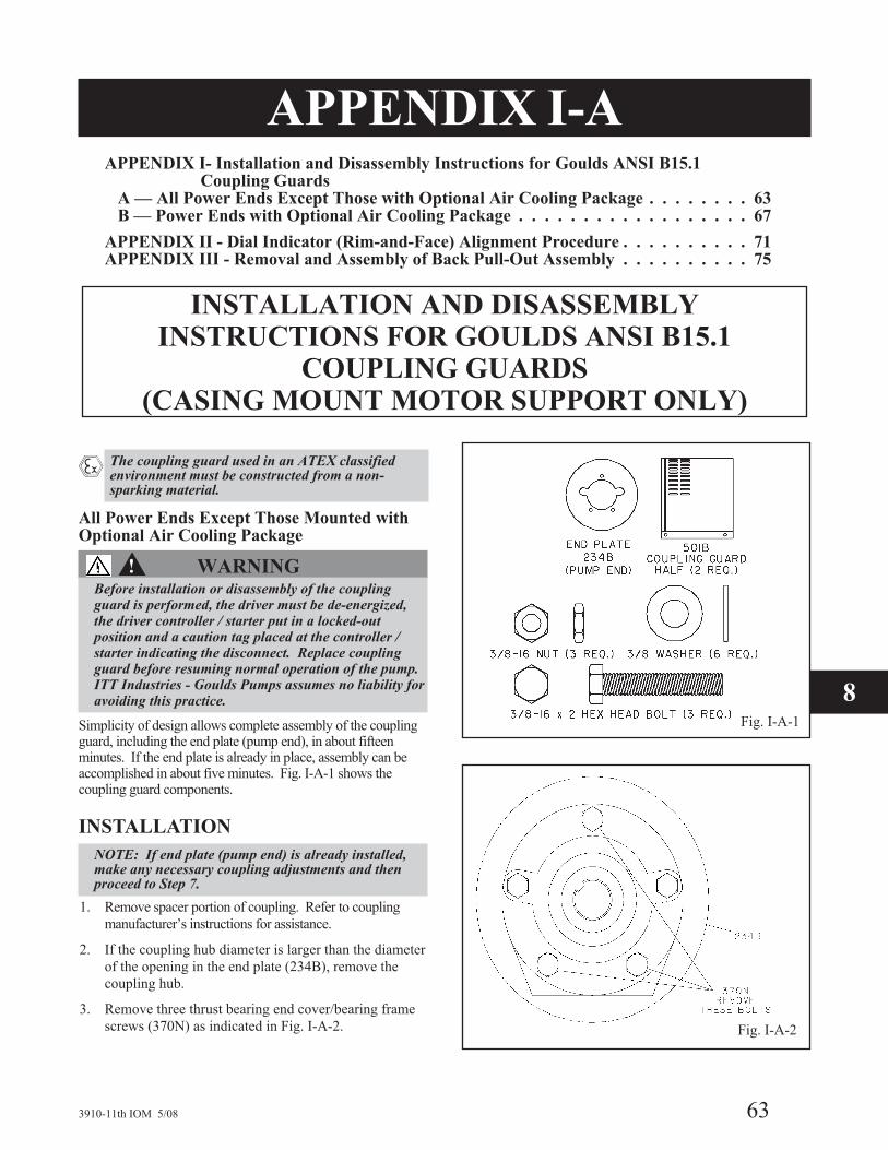
APPENDIX I-AAPPENDIX I- Installation and Disassembly Instructions for Goulds ANSI B15.1
Coupling GuardsA — All Power Ends Except Those with Optional Air Cooling Package . . . . . . . . 63B — Power Ends with Optional Air Cooling Package . . . . . . . . . . . . . . . . . . 67
APPENDIX II - Dial Indicator (Rim-and-Face) Alignment Procedure . . . . . . . . . . 71APPENDIX III - Removal and Assembly of Back Pull-Out Assembly . . . . . . . . . . 75
INSTALLATION AND DISASSEMBLYINSTRUCTIONS FOR GOULDS ANSI B15.1
COUPLING GUARDS(CASING MOUNT MOTOR SUPPORT ONLY)
� The coupling guard used in an ATEX classifiedenvironment must be constructed from a non-sparking material.
All Power Ends Except Those Mounted withOptional Air Cooling Package
�! WARNINGBefore installation or disassembly of the couplingguard is performed, the driver must be de-energized,the driver controller / starter put in a locked-outposition and a caution tag placed at the controller /starter indicating the disconnect. Replace couplingguard before resuming normal operation of the pump.ITT Industries - Goulds Pumps assumes no liability foravoiding this practice.
Simplicity of design allows complete assembly of the couplingguard, including the end plate (pump end), in about fifteenminutes. If the end plate is already in place, assembly can beaccomplished in about five minutes. Fig. I-A-1 shows thecoupling guard components.
INSTALLATION
NOTE: If end plate (pump end) is already installed,make any necessary coupling adjustments and thenproceed to Step 7.
1. Remove spacer portion of coupling. Refer to coupling
manufacturer’s instructions for assistance.
2. If the coupling hub diameter is larger than the diameter
of the opening in the end plate (234B), remove the
coupling hub.
3. Remove three thrust bearing end cover/bearing frame
screws (370N) as indicated in Fig. I-A-2.
3910-11th IOM 5/08 63
Fig. I-A-1
Fig. I-A-2
8
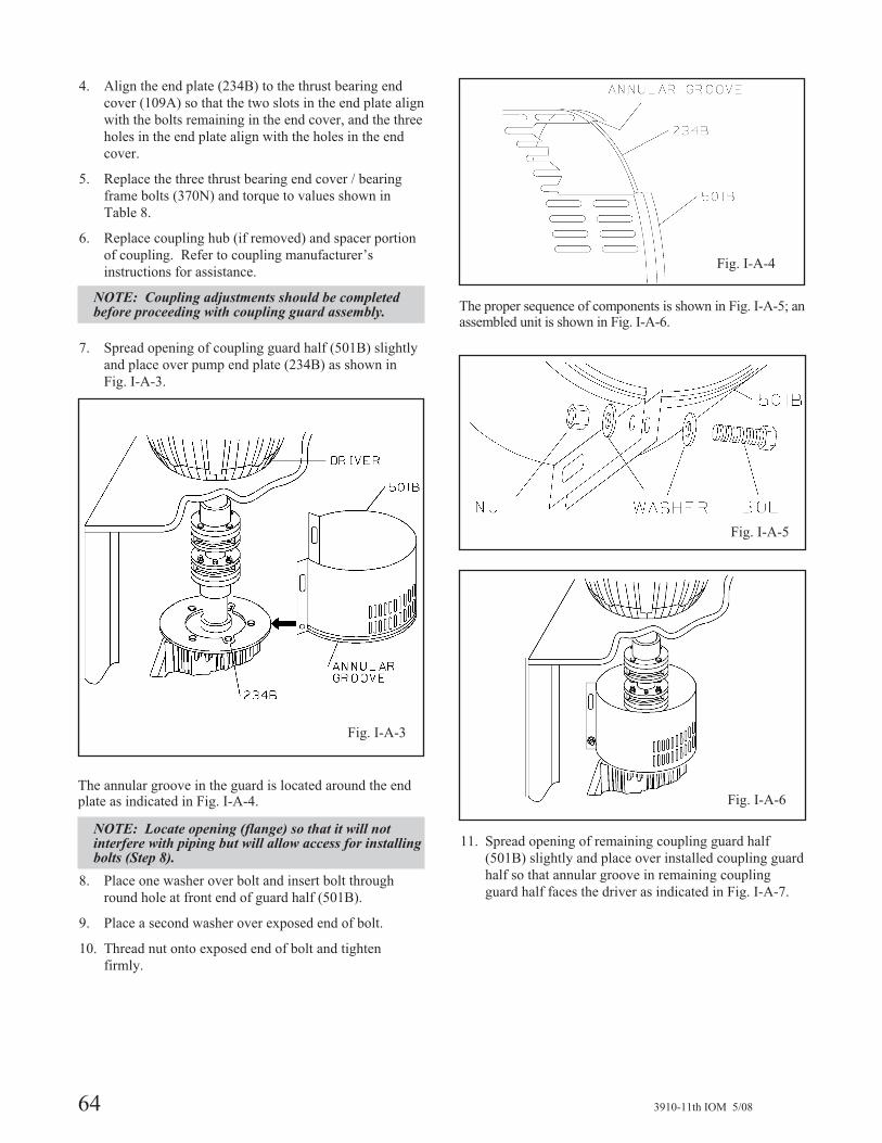
4. Align the end plate (234B) to the thrust bearing end
cover (109A) so that the two slots in the end plate align
with the bolts remaining in the end cover, and the three
holes in the end plate align with the holes in the end
cover.
5. Replace the three thrust bearing end cover / bearing
frame bolts (370N) and torque to values shown in
Table 8.
6. Replace coupling hub (if removed) and spacer portion
of coupling. Refer to coupling manufacturer’s
instructions for assistance.
NOTE: Coupling adjustments should be completedbefore proceeding with coupling guard assembly.
7. Spread opening of coupling guard half (501B) slightly
and place over pump end plate (234B) as shown in
Fig. I-A-3.
The annular groove in the guard is located around the endplate as indicated in Fig. I-A-4.
NOTE: Locate opening (flange) so that it will notinterfere with piping but will allow access for installingbolts (Step 8).
8. Place one washer over bolt and insert bolt through
round hole at front end of guard half (501B).
9. Place a second washer over exposed end of bolt.
10. Thread nut onto exposed end of bolt and tighten
firmly.
The proper sequence of components is shown in Fig. I-A-5; anassembled unit is shown in Fig. I-A-6.
11. Spread opening of remaining coupling guard half
(501B) slightly and place over installed coupling guard
half so that annular groove in remaining coupling
guard half faces the driver as indicated in Fig. I-A-7.
64 3910-11th IOM 5/08
Fig. I-A-3
Fig. I-A-4
Fig. I-A-5
Fig. I-A-6

12. Repeat steps 8-10 for rear end of coupling guard half
(501B), except that nut should be finger tightened only.
13. Adjust length of coupling guard to completely cover
shafts and coupling as shown in Fig. I-A-8 by sliding rear
coupling guard half (501B) towards motor.
14. Repeat steps 8-10 for center slots in coupling guard.
15. Tighten all nuts on the guard assembly firmly.
DISASSEMBLYThe coupling guard must be removed for certainmaintenance and adjustments to the pump, such asadjustment of the coupling. The coupling guard should bereplaced after maintenance is completed.
�! WARNINGBefore assembly or disassembly of the coupling guardis performed, the driver must be de-energized, thedriver controller / starter put in a locked-out positionand a caution tag placed at the controller / starterindicating the disconnect. Replace coupling guardbefore resuming normal operation of the pump. ITTIndustries - Goulds Pumps assumes no liability foravoiding this practice.
�! WARNINGDO NOT resume normal pump operation with thecoupling guard removed.
1. Remove nut, bolt, and washers from center slotted
hole in the coupling guard assembly.
2. Slide driver end coupling guard half (501B) towards
pump (Fig. I-A-8).
3. Remove nut, bolt, and washers from driver coupling
guard half (501B).
4. Spread opening of driver coupling guard half
(501B) slightly and lift over remaining coupling guard
half (Fig. I-A-7).
5. Remove nut, bolt, and washers from remaining
coupling guard half (501B).
6. Spread bottom of coupling guard half slightly and
lift off pump end plate (234B) (Fig. I-A-3).
This completes disassembly of the coupling guard.
NOTE: It is not necessary to remove the end plate(pump end) from the pump bearing frame. Beforeremoving other components, refer to Disassemblysection of this manual.
3910-11th IOM 5/08 65
8
Fig. I-A-8
Fig. I-A-7

66 3910-11th IOM 5/08

APPENDIX I-B
INSTALLATION AND DISASSEMBLYINSTRUCTIONS FOR GOULDS ANSI B15.1
COUPLING GUARDS(CASING MOUNT MOTOR SUPPORT ONLY)
� The coupling guard used in an ATEX classifiedenvironment must be constructed from a non-sparking material.
Power Ends with OptionalAir Cooling Package
�! WARNINGBefore installation or disassembly of the couplingguard is performed, the driver must be de-energized,the driver controller/starter put in a locked-out positionand a caution tag placed at the controller/starterindicating the disconnect. Replace coupling guardbefore resuming normal operation of the pump. ITTIndustries - Goulds Pumps assumes no liability foravoiding this practice.
Simplicity of design allows complete assembly of thecoupling guard, including the thrust end deflector fan guardsupport, in about twenty minutes. If the guard support isalready in place, assembly can be accomplished in aboutten minutes. Fig. I-B-1 shows the coupling guardcomponents.
INSTALLATION
NOTE: If deflector fan guard support is alreadyinstalled, make any necessary coupling adjustmentsand then proceed to step 11.
1. Remove spacer portion of coupling. Refer to coupling
manufacturer’s instruction for assistance.
2. If the coupling hub diameter is larger than the diameter
of the opening in the deflector fan guard support
(234D), remove the coupling hub.
3. Loosen thrust deflector fan set screw (222)(Fig. I-B-2).
4. Slide thrust deflector fan (123E) off shaft (122).
5. Remove thrust bearing end cover/bearing frame screws
(370N) (Fig. I-B-3).
3910-11th IOM 5/08 67
8Fig. I-B-2
Fig. I-B-1
Fig. I-B-3

6. Align the thrust deflector fan guard support (234D) to the
thrust bearing end cover (109A) so that the slots in the
support align with the holes in the end cover.
7. Replace the thrust bearing end cover/bearing frame
screws (370N) and torque to values shown in Table 8.
� !CAUTION
Do not over tighten thrust bearing end cover/ bearingframe screws.
8. Install thrust deflector fan (123E) over shaft
(Fig. I-B-2).
9. Position thrust deflector fan (123E) approximately 0.8
mm (.030 in.) from thrust bearing end cover (109A)
and tighten deflector set screw (222) firmly.
10. Slide thrust deflector fan guard (234) over guard
support (234D) and align holes in guard with tapped
holes in guard support (Fig. I-B-4).
11. Install thrust deflector fan guard/support screws
(469Q) and tighten to value shown in Table 8.
12. Replace coupling hub (if removed) and spacer portion
of coupling. Refer to coupling manufacturer’s
instructions for assistance.
NOTE: Coupling adjustments should be completedbefore proceeding with coupling guard assembly.
13. Spread opening of coupling guard half (501B) slightly
and place over thrust deflector fan guard (234) so that
annular groove in guard half locates around guard
support extension (Fig. I-B-5 and I-B-6).
NOTE: Locate opening (flange) so that it will notinterfere with piping but will allow access for installingbolts (Step 14).
14. Place one washer over bolt and insert bolt through
round hole at front end of guard half (501B).
15. Place a second washer over exposed end of bolt and
tighten firmly.
16. Thread nut onto exposed end of bolt and tighten
firmly.
The proper sequence of components is shown inFig. I-B-7; an assembled unit is shown in Fig. I-B-8.
68 3910-11th IOM 5/08
Fig. I-B-4
Fig. I-B-5
Fig. I-B-6
Fig. I-B-7

17. Spread opening of remaining coupling guard half
(501B) slightly and place over installed coupling guard
half so that annular groove in remaining coupling
guard half faces the driver (Fig. I-B-9).
18. Repeat steps 14-16 for rear end of coupling guard half
(501B), except that nut should be finger tightened only.
19. Adjust length of coupling guard to completely cover
shafts and coupling as shown in Fig. I-B-10 by sliding
rear coupling guard half (501B) towards motor.
20. Repeat steps 14-16 for center slots in coupling guards.
21. Tighten all nuts on the guard assembly firmly.
DISASSEMBLYThe coupling guard must be removed for certainmaintenance and adjustments to the pump, such asadjustment of the coupling. The coupling guard should bereplaced after maintenance is completed.
�! WARNINGBefore assembly or disassembly of the coupling guardis performed, the driver must be de-energized, thedriver controller / starter put in a locked-out positionand a caution tag placed at the controller / starterindicating the disconnect. Replace coupling guardbefore resuming normal operation of the pump. ITTIndustries - Goulds Pumps assumes no liability foravoiding this practice.
�! WARNINGDO NOT resume normal pump operation with thecoupling guard removed.
1. Remove nut, bolt and washers from center slotted hole
in the coupling guard assembly.
2. Slide driver end coupling guard half (501B) towards
pump (Fig. I-B-10).
3. Remove nut, bolt and washers from driver coupling
guard half (501B).
4. Spread opening of driver coupling guard half (501B)
slightly and lift over remaining coupling guard half
(Fig. I-B-9).
5. Remove nut, bolt and washers from remaining
coupling guard half (501B).
6. Spread bottom of coupling guard half slightly and lift
off pump end plate (234B) (Fig. I-B-5).
This completes disassembly of the coupling guard.
NOTE: It is not necessary to remove the thrustdeflector fan guard from the pump bearing frame.Before removing other components, refer toDisassembly section of this manual.
3910-11th IOM 5/08 69
8
Fig. I-B-9
Fig. I-B-10
Fig. I-B-8

70 3910-11th IOM 5/08

APPENDIX IIDIAL INDICATOR (RIM-AND-FACE)
ALIGNMENT PROCEDURE
� Alignment procedures must be followed to preventunintended contact of rotating parts. Followcoupling manufacturer's installation and operationprocedures.
Appendix II details the procedure to be followed whenusing the dial indicator (rim-and-face) method of aligningpump and motor shafts.
Other alignment methods (reverse dial indicator, laser) areacceptable. Maximum allowable misalignment criteria for thesemethods is shown in the Alignment Procedure.
Good alignment is achieved when the dial indicatorreadings as specified in this alignment procedure are equalto 0.05 mm (.002 in.) Total Indicator Reading (T.I.R.) orless when the pump and driver are at operating temperature(Final Alignment).
SET UP1. Mount two dial indicators on the pump coupling half X so
they contact the driver coupling half Y (Fig. II-A).
2. Check setting of indicators by rotating coupling half X
to ensure indicators stay in contact with coupling half
Y but do not bottom out. Adjust indicators
accordingly.
MEASUREMENTTo ensure accuracy of indicator readings:
1. Always rotate both coupling halves together so
indicators contact the same point on coupling half Y.
This will eliminate any measurement problems due to
runout on coupling half Y.
2. Take indicator measurements with driver hold-down
bolts tightened. Loosen hold-down bolts prior to
making alignment corrections.
3. Take care not to damage indicators when moving
driver during alignment corrections.
ANGULAR ALIGNMENTA unit is in angular alignment when indicator A (angularindicator) does not vary by more than 0.05 mm (.002 in.) asmeasured at four points 90° apart at operating temperature.
Axial Correction1. Zero indicator A on suction / discharge centerline
(12 o’clock) towards the suction (Fig. II-B).
2. Rotate indicators/coupling halves 180° (6 o’clock).
Observe needle and record reading.
3a. Negative Reading - The coupling halves are farther
apart at the second (6 o’clock) position than at the
intial (12 o’clock) position. Correct by adding shims
in line with the (12 o’clock) position, or by removing
shims in line with the (6 o’clock) position (Fig. II-B).
3b. Positive Reading - The coupling halves are farther
apart at the intial (12 o’clock) position than at the
second (6 o’clock) position. Correct by adding shims
in line with the (6 o’clock) position, or by removing
shims in line with the (12 o’clock) position (Fig. II-B).
3910-11th IOM 5/08 71
8
Fig. II-A

4. Repeat steps 1 through 3 until indicator A reads 0.05
mm (.002 in.) or less.
Transverse Correction1. Zero indicator A on transverse centerline, 90°
clockwise from suction centerline (3 o’clock,
Fig. II-C).
2. Rotate indicators/coupling halves 180°.
3a. Negative Reading - The coupling halves are farther
apart at the second (9 o’clock) position than at the
initial (3 o’clock) position. Correct by adding shims in
line with the (3 o’clock) position, or by removing
shims in line with the (9 o’clock) position (Fig. II-C).
3b. Positive Reading - The coupling halves are farther
apart at the initial (3 o’clock) position than at the
second (9 o’clock) position. Correct by adding shims
in line with the (9 o’clock) position, or by removing
shims in line with the (3 o’clock) position (Fig. II-C).
NOTE: Drive trains of over 450 pounds are suppliedwith adjustment provisions fastened to the motorsupport which may be used to make all horizontalalignment corrections.
4. Repeat steps 1 through 3 until indicator A reads
0.05 mm (.002 in.) or less.
5. Re-check both axial and transverse readings to ensure
adjustment of one did not disturb the other. Correct as
necessary.
PARALLEL ALIGNMENTA unit is in parallel alignment when indicator P (parallelindicator) does not vary by more than 0.05 mm (.002 in.) asmeasured at four points 90° apart at operating temperature,or when the shaft centerlines are within the recommendedcold setting criteria as shown in Table II-1.
Table II-1Cold Setting of Parallel
Vertical Alignment
Driver Type Set Driver Shaft
Electric Motor 0.05 - 0.10 mm LOW(.002 - .004 in. LOW)
Axial Correction1. Zero indicator P on suction/discharge centerline (12
o’clock) towards the suction (Fig. II-D).
2. Rotate indicator/coupling halves 180° (6 o’clock). Observe
needle and record reading.
3a. Negative Reading - Coupling half X is farther from the
suction than coupling half Y. Correct by moving driver
away from the suction a distance equal to one-half that
of the total reading (Fig. II-D).
3b. Positive Reading - Coupling half X is closer to the
suction than coupling half Y. Correct by moving driver
towards the suction a distance equal to one-half that of
the total reading (Fig. II-D).
NOTE: Equal amounts of shims must be added to orremoved from entire driver face, or the vertical angularalignment will be affected.
4. Repeat steps 1 through 3 until indicator P reads 0.05
mm (.002 in.) or less when hot, or per Table II-1 when
cold.
72 3910-11th IOM 5/08
Fig. II-B
Fig. II-C Fig. II-D
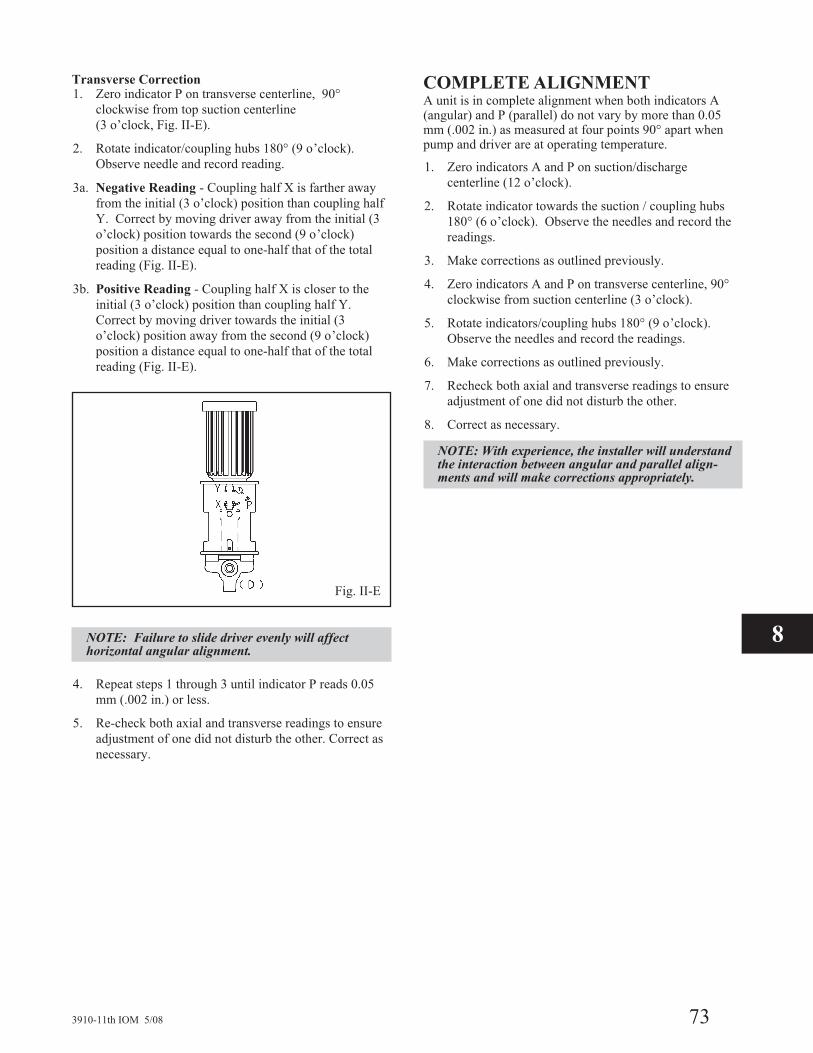
Transverse Correction1. Zero indicator P on transverse centerline, 90°
clockwise from top suction centerline
(3 o’clock, Fig. II-E).
2. Rotate indicator/coupling hubs 180° (9 o’clock).
Observe needle and record reading.
3a. Negative Reading - Coupling half X is farther away
from the initial (3 o’clock) position than coupling half
Y. Correct by moving driver away from the initial (3
o’clock) position towards the second (9 o’clock)
position a distance equal to one-half that of the total
reading (Fig. II-E).
3b. Positive Reading - Coupling half X is closer to the
initial (3 o’clock) position than coupling half Y.
Correct by moving driver towards the initial (3
o’clock) position away from the second (9 o’clock)
position a distance equal to one-half that of the total
reading (Fig. II-E).
NOTE: Failure to slide driver evenly will affecthorizontal angular alignment.
4. Repeat steps 1 through 3 until indicator P reads 0.05
mm (.002 in.) or less.
5. Re-check both axial and transverse readings to ensure
adjustment of one did not disturb the other. Correct as
necessary.
COMPLETE ALIGNMENTA unit is in complete alignment when both indicators A(angular) and P (parallel) do not vary by more than 0.05mm (.002 in.) as measured at four points 90° apart whenpump and driver are at operating temperature.
1. Zero indicators A and P on suction/discharge
centerline (12 o’clock).
2. Rotate indicator towards the suction / coupling hubs
180° (6 o’clock). Observe the needles and record the
readings.
3. Make corrections as outlined previously.
4. Zero indicators A and P on transverse centerline, 90°
clockwise from suction centerline (3 o’clock).
5. Rotate indicators/coupling hubs 180° (9 o’clock).
Observe the needles and record the readings.
6. Make corrections as outlined previously.
7. Recheck both axial and transverse readings to ensure
adjustment of one did not disturb the other.
8. Correct as necessary.
NOTE: With experience, the installer will understandthe interaction between angular and parallel align-ments and will make corrections appropriately.
3910-11th IOM 5/08 73
Fig. II-E
8

74 3910-11th IOM 5/08

APPENDIX IIIREMOVAL AND INSTALLATION OFBACK PULL-OUT ASSEMBLY USING
GOULDS BACK PULL-OUT REMOVAL DEVICE
�! WARNING
Before removal of the back pull-out assembly, thedriver must be de-energized, the driver controller/starter put in a locked-out position and a caution tagplaced at the starter indicating the disconnect.
�! WARNING
Pump components are heavy. Proper methods oflifting must be employed to avoid physical injuryand/or equipment damage.
Goulds back pull-out removal device provides the safestknown method for installation and removal of the backpull-out assembly and was developed to meet safetyrequirements. Other methods for removal andinstallation of the back pull-out do not incorporatethese safety features, and are not recommended. ITTIndustries - Goulds Pumps assumes no liability foravoiding this practice.
Simplicity of design allows complete removal of the Model3910 back pull-out assembly safely and quickly.Components of the standard Goulds back pull-out removaldevice are shown in Fig. III-A, and are:
Back pull-out removal device frame
• ½ in. - 13 eye nut (1)
• ½ in. bolt (1)
• ½ in. washers (2)
• ¾ - 10 bolts (2)
• ¾ - 10 nuts (2)
• ¾ in. washers (4)
• ½ in. hex cap screws (4)
• ½ in. coupling nuts (2)
• ½ in. jam nuts (2)
• ½ in. eyebolt (1)
• Spherical washer (1)
• ¾ in. sleeve (1)
• Bearing frame brackets (2)
• ½ in. threaded rod (2 parts)
3910-11th IOM 5/08 75
Fig. III-A
8

The optional, adjustable removal device (Fig III-B)replaces the standard one-piece removal device with atwo-piece, adjustable unit which can accommodate lessheadroom (with smaller drivers), and greater length (forlonger drivers).
Additonal parts are:
• Back pull-out removal device (upper and lower halves) -replaces standard frame.
• ½ in. bolt (2)
• ½ in. washers (4)
• ½ in. nuts (2)
PREPARATION FOR REMOVAL OFBACK PULL-OUT ASSEMBLY1. Valves must be closed and liquid drained from pumps,
as indicated in Disassembly section.
2. Auxilliary piping, tubing and equipment that could
interfere with removal of the back pull-out must be
removed, as indicated in Disassembly section.
3. Coupling guard must be removed, as described in
Appendix I.
4. Coupling spacer must be removed, as described in
Appendix I.
5. Seal chamber cover / casing stud nuts (425) must be
removed, and jacking bolts (418) tightened to separate
back pull-out from casing (100), as indicated in
Disassembly section.
ASSEMBLY OF GOULDS BACKPULL-OUT REMOVAL DEVICE
Standard1. Thread ½ in. hex jam nut on eyebolt until approxi-
mately 1 in. (25mm) of threads remain between the nut
and the end of the eyebolt.
2. Thread one ½ in. coupling nut on eyebolt and tighten
against jam nut.
3. Thread ½ in. hex nut on threaded rod until
approximately 1 in. (25mm) of threads have been
revealed between the nut and end of the threaded rod.
4. Thread rod into coupling nut until jam nut contacts
coupling nut.
5. Tighten jam nut against coupling nut.
6. Insert sleeve through eye of eyebolt.
7. Place one bracket around sleeve so that large holes in
bracket align with holes in sleeve.
8. Insert one ¾ in. bolt through washer, brackets and
sleeve.
9. Place ¾ in. washer and nut on exposed, threaded end of
bolt and tighten nut against washer.
10. Place second bracket around sleeve in lower leg of
removal device so that large holes in bracket align with
holes in sleeve.
11. Insert second ¾ in. bolt through washer, bracket and
sleeve.
12. Place ¾ in. washer and nut on exposed, threaded end
of bolt and tighten nut against washer.
76 3910-11th IOM 5/08
Fig. III-B

13. Place ½ in. bolt through washer and appropriate hole in
upper leg of removal device.
NOTE: Generally, the second hole from the open endof the upper portion of the removal device gives bestresults. Other holes have been provided for individualadjustments.
14. Place ½ in. washer onto exposed, threaded end of bolt,
thread on ½ in. eye nut and tighten against washer.
Optional (Adjustable)1. Follow steps 1-14 as described under Standard.
2. Measure distance between lower mounting bracket
location on bearing frame (228) and top of driver.
3. Insert lower half of removal device into upper half
until measured distance between bracket and upper leg
is equal to the distance measured in Step 2.
4. Extend length of removal device by pulling lower half
from upper half until next set of adjusting holes in
upper and lower halves align.
5. Insert two ½ in. bolts through washers and adjusting
holes in upper and lower halves of removal device.
6. Place ½ in. washer and nuts on exposed, threaded ends
of two bolts and tighten nuts against washers.
REMOVAL OF BACK PULL-OUTASSEMBLY1. Remove grease fittings or oil mist connections (193)
from bearing frame (228).
2. Fasten upper (first) bracket assembly to upper
machined boss on bearing frame (228) with two ½ in.
bolts (Fig. III-C).
3. Rig sling to eye nut installed in upper leg of removal
device and to overhead lifting device.
4. Lift removal device and bracket assembly with
overhead lifting device and position lower bracket on
lower machined boss of bearing frame (228) so that
holes in bracket align with threaded holes in frame.
5. Fasten lower (second) bracket to lower machined boss
on bearing frame (228) with two ½ in. bolts.
6. Guide threaded rod through mating hole in upright
portion of removal device while raising upper leg.
7. Place spherical washer (two pieces), ½ in. flat washer
and second ½ in. coupling nut on exposed end of
threaded rod and tighten nut against washer.
NOTE: At this point, upright of removal device shouldbe vertical and parallel with centerline of shaft. If not,determine cause and correct.
8. Lift back pull-out assembly/removal device assembly
vertically until seal chamber cover/ stuffing box cover
(184) clears casing studs (356A) (Fig III-D).
3910-11th IOM 5/08 77
Fig III-C
Fig III-D
8

� CAUTION
Do not allow coupling halves or other components tomake contact, as damage to coupling and/or othercomponents could result.
9. Tighten coupling nut on threaded rod to tilt top of back
pull-out assembly towards upright of removal device
(Fig III-E).
10. Repeat steps 8 and 9 until seal chamber cover/ stuffing
box cover (184) aligns with cutout in motor support
(240) and coupling clears top flange of motor support.
11. Move bearing frame assembly/removal device
assembly horizontally until clear of motor support
(240) (Fig III-F).
NOTE: In some cases, it may be necessary to loosenthe coupling guard end plate from the thrust bearingend cover to gain sufficient clearance. Followcoupling guard installation and disassemblyinstructions in Appendix I.
NOTE: With experience, maintenance personnel willunderstand the interactions between vertical androtational movements of the bearing frameassembly/removal device assembly and will makeadjustments appropriately.
12. Follow the remaining instructions in Disassembly.
INSTALLATION OF BACKPULL-OUT ASSEMBLYReverse steps in Removal of Back Pull-Out Assembly,previously described in this appendix.
78 3910-11th IOM 5/08
Fig III-E
Fig III-F

3910-11th IOM 5/08 79
8

HOW TO ORDER PARTS
When ordering parts, call
1-800-446-8537
or your local ITT Industries - Goulds Representative
EMERGENCY SERVICE
Emergency parts service is available
24 hours / day 365 days / year . . .
Call 1-800-446-8537
Form No. I3910-11 5/08 © copyright 2004 Goulds Pumps, Incorporated
a subsidiary of ITT Industries, Inc.
Visit our website at www.gouldspumps.com.