installation, operation, and maintenance - trane · installation, operation, and maintenance...
TRANSCRIPT

LPC-SVX01C-EN
Installation, Operation,and Maintenance
Packaged Climate Changer
Air Handler
Model LPC
“FO” and later design sequence1,500 to 15,000 cfm
July 2006

© 2006 American Standard All rights reserved LPC-SVX01C-EN
About This Manual
Literature Change History
Use this manual for Packaged ClimateChanger air handlers, model LPC. This isthe first revision of this manual. Itprovides specific installation, operation,and maintenance instructions for “DO”and later design sequences. Forprevious design sequence information,contact your local Trane representative.
Warnings and Cautions
Warnings and cautions appear atappropriate sections throughout thismanual. Read these carefully.
WARNINGIndicates a potentially hazardoussituation, which could result in deathor serious injury if not avoided.
CAUTIONIndicates a potentially hazardoussituation, which may result in minoror moderate injury if not avoided.Also, it may alert against unsafepractices.
CAUTIONIndicates a situation that may resultin equipment or property-damage-only accidents.
generalinformation
Sample Warnings and Cautions
WARNINGHazardous Voltage w/Capacitors!Disconnect all electric power,including remote disconnects anddischarge all motor start/runcapacitors before servicing. Followproper lockout/tagout procedures toensure the power cannot beinadvertently energized. Verify withan appropriate voltmeter that allcapacitors have discharged. Failure todisconnect power and dischargecapacitors before servicing couldresult in death or serious injury.
CAUTIONUse Copper Conductors Only!Unit terminals are not designed toaccept other types of conductors.Failure to use copper conductors mayresult in equipment damage.
Special Note on RefrigerationEmissions
World environmental scientists haveconcluded that ozone in our upperatmosphere is being reduced due to therelease of CFC fully halogenatedcompounds.
Trane urges all HVAC service personnelto make every effort to prevent anyrefrigerant emissions while installing,operating, or servicing equipment.Always conserve refrigerants forcontinued use.
Additional specific information onrefrigerant handling is included in thismanual where applicable.
Common HVAC AcronymsFor convenience, a number of acronymsand abbreviations are used throughoutthis manual. These acronyms arealphabetically listed and defined below.
BAS = Building automation systemscfm = Cubic-feet-per-minuteewt = entering water temperatureF/A = Fresh airHVAC = Heating, ventilation and airconditioningI/O = Inputs/outputsIOM= Installation, operation, andmaintenace manualLH = Left-handO/A = Outside airR/A = Return airRH = Right-handrpm = Revolutions-per-minuteS/A = Supply airw.c. = Water columnZSM = Zone sensor module

LPC-SVX01C-EN 3
contents
Cross reference to related publications/information for model LPC units with TracerAH540 controls:• Installation, Operation, and Programming Guide for Tracer AH540 Unit Controller,
CNT-SVX05B-EN• Packaged Climate Changer Air Handler Catalog, CLCH-PRC007-EN
Installation ……………………………………………………………2
general information ……………………………………………2dimensions & weights ………………………………………14pre-installation considerations ………………………………27mechanical requirements …………………………………29electrical requirements ………………………………………33installation procedure ………………………………………36pre-startup requirements ……………………………………40
Operation ……………………………………………………………43
general information …………………………………………43sequence of operation ………………………………………59
Maintenance…………………………………………………………86
diagnostics ……………………………………………………86troubleshooting ………………………………………………89maintenance procedures ……………………………………96appendix ………………………………………………………99

4 LPC-SVX01C-EN
General
Packaged Climate Changer units aredraw-through air handlers that aredesigned for cooling and/or heatingconditions of 1,500 to 15,000 nominal cfm.
Basic unit components consist of coil(s),condensate drain pan, filter, one fanwheel, motor and drive.
Unit control options range from thesimple control interface for field-mountedcontrollers to the sophisticated TracerAH540. For more information on theTracer AH540 controls, see the Operationsection of this manual.
Refrigerant HandlingProcedures
Environmental Accountability PolicyTrane urges that all HVAC servicers tomake every effort to eliminate, if possible,or vigorously reduce the emission of CFC,HCFC, and HFC refrigerants to theatmosphere. Always act in a responsiblemanner to conserve refrigerants forcontinued usage even when acceptablealternatives are available.
Recover and Recycle RefrigerantsNever release refrigerant to theatmosphere! Always recover and/orrecycle refrigerant for reuse,reprocessing (reclaimed), or properlydispose if removing from equipment.Always determine the recycle or reclaimrequirements of the refrigerant beforebeginning the recovery procedure. Obtaina chemical analysis of the refrigerant ifnecessary. Questions about recoveredrefrigerant and acceptable refrigerantquality standards are addressed in ARIStandard 700.
generalinformation
Refrigerant Handling and SafetyConsult the manufacturer’s materialsafety data sheet (MSDS) for informationon refrigerant handling to fullyunderstand health, safety, storage,handling, and disposal requirements. Usethe approved containment vessels andrefer to appropriate safety standards.Comply with all applicable transportationstandards when shipping refrigerantcontainers.
Service Equipment and ProceduresTo minimize refrigerant emissions whilerecovering refrigerant, use themanufacturer’s recommended recyclingequipment per the MSDS. Useequipment and methods which will pullthe lowest possible system vacuum whilerecovering and condensing refrigerant.Equipment capable of pulling a vacuum ofless than 1,000 microns of mercury isrecommended.
Do not open the unit to the atmospherefor service work until refrigerant is fullyremoved/recovered. When leak-testingwith trace refrigerant and nitrogen, useHCFC-22 (R-22) rather than CFC-12 (R-12) or any other fully-halogenatedrefrigerant . Be aware of any new leaktest methods which may eliminaterefrigerants as a trace gas. Performevacuation prior to charging with avacuum pump capable of pulling avacuum of 1,000 microns of mercury orless. Let the unit stand for 12 hours andwith the vacuum not rising above 2,500microns of mercury.
A rise above 2,500 microns of mercuryindicates a leak test is required to locateand repair any leaks. A leak test isrequired on any repaired area.
Charge refrigerant into the equipmentonly after equipment does not leak orcontain moisture. Reference properrefrigerant charge requirements in themaintenance section of this manual toensure efficient machine operation. Whencharging is complete, purge or draincharging lines into an approved refriger-ant container. Seal all used refrigerantcontainers with approved closure devicesto prevent unused refrigerant fromescaping to the atmosphere. Take extracare to properly maintain all serviceequipment directly supporting refrigerantservice work such as gauges, hoses,vacuum pumps, and recycling equipment.
When cleaning system components orparts, avoid using CFC-11 (R-11) or CFC-113 (R-113). Use only cleaning-solventsthat do not have ozone depletion factors.Properly dispose of used materials.Refrigeration system cleanup methodsusing filters and driers are preferred.Check for leaks when excessive purgeoperation is observed.
Keep abreast of unit enhancements,conversion refrigerants, compatibleparts, and manufacturer’s recommenda-tions that will reduce refrigerant emis-sions and increase equipment operatingefficiencies.

LPC-SVX01C-EN 5
Figure I-GI-1. Packaged Climate Changer air handler unit components. Horizontal unit is shown.
Installationgeneralinformation
Galvanized steel cabinet• matt-faced insulation• foil face insulation optional• double wall insulation optional• 2-inch flat filter option on main
sectionInternal filter frameaccommodatestwo-inch filters Sizes: 03, 06, 09, 10, 12, 14, 17, 21, 25
or 30 square feet• 1,500 to 15,000 cfm (708 to 4956 l/s)• UL/CUL listing• ARI 410 and 430 listed• Meets ARI 260 acoustic ratings
Up to 8 rows of coil• 4 or 6 row DX coil with 9,
12, or 14 fpi• 4, 6, or 8-row chilled water
with 9, 12, or 14 fpi• 1 or 2-row hot water coil,
reheat or preheat with 9,12, or 14 fpi
• 1-row steam coil, 6 fpi,reheat or preheat
Forward-curved fan
• fixed pitch or variablepitch sheaves
• constant volume orvariable air volume
Control options• control interface• Tracer AH540
DDC controller
Belt-driven motor• Internal spring isolation
optional• 1/2 to 20 hp• 650 to 1900 rpm
Access section option• with or without preheat coil• one or two-row hot water
(9, 12, or 14 fpi) or• one-row steam distributing
coil (6 fpi)
Filter section option• 2-inch, MERV 7, angle filters• 4-inch, MERV 7, flat filters• 4-inch, MERV 12, flat filters
Other options include:• electric heat with single-point
power connections, reheatposition
• factory mounted and wireddisconnect with motoroverloads
• variable frequency drive factorymounted and wired
Face & bypass optionhelps control preheat
6 LPC-SVX01C-EN
Ultraviolet (UV) GermicidalIrradiation Lights
The United States EnvironmentalProtection Agency (EPA) believes thatmolds and bacteria inside buildings havethe potential to cause health problems insensitive individuals (Note 1). If specified,Trane provides ultraviolet lights (UV-C) asa factory-engineered and installed optionin select commercial air handlingproducts for the purpose of reducingmicrobiological growth (mold andbacteria) within the equipment. Whenfactory provided, polymer materials thatare susceptible to deterioration by theUV-C light will be substituted or shieldedfrom direct exposure to the light. Inaddition, UV-C radiation can damagehuman tissue, namely eyes and skin. Toreduce the potential for inadvertentexposure to the lights by operating andmaintenance personnel, electricalinterlocks that automatically disconnectpower to the lights are provided at all unitentry points to equipment where lightsare located
Note:1. United States Environmental Protec-tion Agency; A Brief Guide to Mold,Moisture and your Home; Brochure EPA402-K-02-003. It’s available online, atwww.epa.gov. Enter “guide to mold” inthe search box to view.
Installationgeneralinformation
WARNINGEquipment Damage FromUltraviolet (UV) Lights!Trane does not recommend fieldinstallation of ultraviolet lights inits air handling equipment for theintended purpose of improvingindoor air quality. High intensityC-band ultraviolet light is knownto severely damage polymer(plastic) materials and poses apersonal safety risk to anyoneexposed to the light withoutproper personal protectiveequipment (can cause damage toeyes and skin). Polymer materialscommonly found in HVACequipment that may besusceptible include insulation onelectrical wiring, fan belts,thermal insulation, variousfasteners and bushings.Degradation of these materialscan result in serious damage tothe equipment. Trane accepts noresponsibility for the performanceor operation of our air handlingequipment in which ultravioletdevices were installed outside ofthe Trane factory.

LPC-SVX01C-EN 7
Installationgeneralinformation
Packaged Climate Changer Unit Configurations and Optional Sections
Available Fan Discharge Configurations Detail
Horizontal Unit, Top Front Fan Discharge
Horizontal Unit, Front Top Fan DischargeVertical Unit, Front Top
Fan Discharge
Vertical Unit, Back Top
Fan Discharge
Vertical Unit, Top Back
Fan Discharge
Vertical Unit, Top Front
Fan Discharge
Electric Heat
Section
OptionalSection
Main Unit Section Configurations
Vertical Unit, Front Top
Discharge
Horizontal Unit, Front Top
Discharge
OR
Top Front
Horizontal Unit Fan
Discharge Option
Top Front Top Back Back Top
Vertical Unit Fan Discharge Options
Face & Bypass
Section
Optional Sections
Flat Filter
Section
Angle Filter
Section OR
Coil Access
Section
Mixing
Section

8 LPC-SVX01C-EN
Installationgeneralinformation
Table I-GI-1. Packaged Climate Changer General Data
Unit size 3 6 8 10 12 14 17 21 25 30Unit nominal airflow, cfm 1500 3000 4000 5000 6000 7000 8500 10500 12500 15000Hydronic & DX coil
coil area, ft2 2.8 5.6 7.5 9.7 12.4 14.3 16.9 20.6 24.2 28.8width, in. 17.5 22.5 27.5 27.5 35.0 35.0 45.0 45.0 51.2 51.2length, in. 23.0 36.0 39.0 51.0 51.0 59.0 54.0 66.0 68.0 81.0velocity, ft./min. 536.7 533.3 537.1 513.3 484.0 488.1 503.7 509.1 516.5 520.3dry weight, lbs. Note 10
1-row 23.5 35.0 41.8 51.5 66.2 72.1 82.8 93.2 109.7 122.5 2-row 29.5 46.3 56.8 70.8 91.0 100.5 116.6 134.2 168.5 190.2 4-row 46.6 75.8 94.7 120.5 152.8 170.7 207.3 240.7 276.3 317.0 6-row 58.6 98.5 124.7 159.3 202.4 227.8 274.9 322.8 372.7 431.2 8-row 73.6 125.4 159.5 204.7 259.4 292.9 351.3 414.5 479.5 556.8wet weight, lbs.Note 10
1-row 29.2 43.6 52.5 64.0 85.8 93.2 108.2 121.5 141.9 158.2 2-row 37.7 59.0 73.0 90.5 119.9 132.4 161.1 184.4 226.6 255.4 4-row 59.8 97.6 123.1 155.7 201.6 225.4 279.1 323.9 373.1 427.8 6-row 76.9 129.4 165.2 210.0 271.2 305.3 374.0 438.9 508.2 587.7 8-row 96.9 165.5 212.2 271.0 348.2 393.3 477.6 563.5 653.7 759.0waterflow limits 1-row min. gpm Note 3 6.1 7.9 9.6 9.6 12.2 12.2 15.7 15.7 17.5 17.5 max. gpm Note 4 32.6 42.0 51.3 51.3 65.3 65.3 83.9 83.9 93.3 93.6 2, 4, 6, & 8-row min. gpm Note 3 6.1 14.9 18.4 18.4 23.6 23.6 30.6 30.6 35.0 35.0 max. gpm Note 4 32.6 79.3 51.3 51.3 65.3 125.9 163.2 163.2 186.6 186.6volume, gallons 1-row 0.7 1.0 1.3 1.5 2.3 2.5 3.1 3.4 3.9 4.3 2-row 1.0 1.5 2.0 2.4 3.5 3.8 5.3 6.0 7.0 7.8 4-row 1.6 2.6 3.4 4.2 5.9 6.6 8.6 10.0 11.6 13.3 6-row 2.2 3.7 4.9 6.1 8.3 9.3 11.9 13.9 16.3 18.8 8-row 2.8 4.8 6.3 7.9 10.6 12.0 15.2 17.9 20.9 24.3Steam coil
area, ft2 1.9 4.5 6.5 8.5 11.7 13.5 6.8 8.4 11.0 13.2width, in. Note 5 12.0 18.0 24.0 24.0 33.0 33.0 18.0 18.0 24.0 24.0length, in. Note 6 23.0 36.0 39.0 51.0 51.0 59.0 54.0 67.0 66.0 79.0area, ft2 Note 7 – – – – – – 9.0 11.2 11.0 13.2width, in. Notes 5 & 7 – – – – – – 24.0 24.0 24.0 24.0length, in. Notes 6 & 7 – – – – – – 54.0 67.0 66.0 79.0weight, lbs. 31.7 54.8 74.8 86.0 114.1 123.3 157.6 179.9 200.0 224.2Fan/motor data
fan wheel size, in. 9x7 12x9 12x12 15x15 18x15 18x18 20x15 20x20 20x18 22x20max rpm 2000 1500 1700 1400 1200 1200 1100 1000 1300 1150motor HP 1/2 - 2 1/2 - 3 3/4 - 5 1 - 5 1 - 7 1/2 1 - 7 1/2 1 -10 2 - 15 3 - 20 3 - 20min. design cfm Note 8 1050 2100 2800 3500 4200 4900 5950 7350 8750 10500max. design cfmNote 9 1800 3600 4800 6000 7200 8400 10200 12600 15000 180002 and 4-in. Flat filter data
quantity - size in. 1 - 20x25 2 - 20x25 2 - 20x25 1 - 16x25 2 - 16x20 2 - 16x20 2 - 16x20 2 - 16x20 2 - 16x25 6 - 16x252 - 20x25 1 - 16x25 1 - 16x25 2 - 16x25 2 - 16x25 6 - 20x25 4 - 20x25
2 - 20x20 2 - 20x20 2 - 20x20 2 - 20x201 - 20x25 1 - 20x25 2 - 20x25 2 - 20x25
area, ft2 3.5 6.9 6.9 9.7 16.3 16.3 22.5 22.5 26.4 30.6nominal air velocity, ft./min. 432.0 432.0 576.0 514.3 369.2 430.8 377.8 466.7 473.5 490.22-in. Angle filter section data
quantity - size in. 2 - 16x25 4 - 20x20 4 - 20x20 4 - 20x20 9 - 20x20 9 - 20x20 6 - 16x25 6 - 16x25 4 - 16x20 12 - 16x202 - 16x20 6 - 20x25 6 - 20x25 12 - 20x20 8 - 20x20
area, ft2 5.6 11.1 11.1 15.6 25.0 25.0 37.5 37.5 42.2 48.9velocity, ft./min. 270.0 270.0 360.0 321.3 240.0 280.0 226.7 280.0 296.2 306.7Mixing section
nominal air velocity, ft./min. 966.4 1066.3 1123.4 1120.4 1184.1 1161.7 1171.1 1120.1 1218.5 1247.1
Notes: 1. Coil width = length in the direction of a coil header, typically vertical. 2. Coil length = length of coil in direction of the coil tubes, typically horizontal and perpendicular to airflow.3. Unit sizes 17-30 have two stacked steam coils. 4. To prevent erosion/noise problems. 5. Coil width = length in the direction of a coil header, typically vertical. 6 . Coil length = length ofcoil in direction of the coil tubes, typically horizontal and perpendicular to airflow. 7. The minimum waterflow is to assure self venting of the coil. There is no minimum water flow limitfor coils that do not require self venting. 8. Minimum airflow limit is for units with hot water, steam, or electric heat. There is no minimum airflow for cooling only units. 9. Due tomoisture carryover limits. 10. Coil weight based on 12 fpi coil.

LPC-SVX01C-EN 9
Installationgeneralinformation
Table I-GI-2. Available motor horsepower and unit voltage
motor horsepowerunit voltage 1/2
3/4 1 1 1/2 2 3 5 7 1/2 10 15 20208/60/1
230/60/1
277/60/1
208/60/3
230/60/3
460/60/3
575/60/3
380/50/3
415/50/3
Table I-GI-3. Available motor horsepower by unit size
motor horsepowerunit size 1/2
3/4 1 1 1/2 2 3 5 7 1/2 10 15 203
6
8
10
12
14
17
21
25
30

10 LPC-SVX01C-EN
Figure I-GI-3. Horizontal Face Split DX CoilFigure I-GI-2. Intertwined DX Coil
Dx Coil Options
Figure I-GI-1. Single Circuit DX Coil
Installationgeneralinformation
Table I-GI-5. Packaged Climate Changer DX Coil Configuration Options
CoilConfiguration Single Horizontal Face Split Intertwined
Unit # # Coil Fin # # Coil Fin # # Coil FinSize Dist. Circuits Width Length Dist. Circuits Width Length Dist. Circuits Width Length
3 1 3 17.5 23.0 – – – – – – – – 6 1 5 22.5 36.0 – – – – – – – – 8 1 7 27.5 39.0 2 7 27.5 39.0 2 7 27.5 39.010 1 10 27.5 51.0 2 10 27.5 51.0 2 10 27.5 51.012 – – – – 2 13 35.0 51.0 2 13 35.0 51.014 – – – – 2 13 35.0 59.0 2 13 35.0 59.017 – – – – 2 17 45.0 54.0 4 17 45.0 54.021 – – – – 2 17 45.0 66.0 4 17 45.0 66.025 – – – – 2 20 51.3 68.0 4 20 51.5 68.030 – – – – 4 40 51.3 81.0 4 40 51.3 81.0
Note: 4-row coils have a 3/16" distributor. 6-row coils have a 1/4" distributor.

LPC-SVX01C-EN 11
Installationgeneralinformation
Packaged Climate Changer Model Number Description
Following is a complete description of the Packaged Climate Changer model number. Each digit in the model number has acorresponding code that identifies specific unit options.
LPC A A 08 F 2 F0 L L B 0 0 000 0 0 A F B H B 0 0 0 0 0 0 0 0 0 0 01,2,3 4 5 6,7 8 9 10,11 12 13 14 15 16 17,18,19 20 21 22 23 24 25 26 27 28 29 30 31 32 33 34 35 36 37
Digit 13 - Unit Coil #1 Type (1st in Air Stream)0 = no unit coil #1hydronic heat coilsA = 1-row, 9 fpiB = 1-row, 12 fpiC = 1-row, 14 fpiD = 2-row, 9 fpiE = 2-row, 12 fpiF = 2-row, 14 fpichilled hydronic coilsG = 4-row, 9 fpiH = 4-row,12 fpiJ = 4-row, 14 fpiK = 6-row, 9 fpiL = 6-row, 12 fpiM = 6-row, 14 fpiN = 8-row, 9 fpiP = 8-row, 12 fpiR = 8-row, 14 fpiDX coils, 3/16” distributorT = 4-row, 9 fpiU = 4-row, 12 fpiV = 4-row, 14 fpiSteam Coil1 = 1-row, 6 fpiDX coils, 1/4” distributor5 = 6-row, 9 fpi6 = 6-row DX, 12 fpi7 = 6-row DX, 14 fpi
Digit 14 - Unit coil #2 type (2nd in airstream)0 = no unit coil #1hydronic reheat coilsA = 1-row, 9 fpiB = 1-row, 12 fpiC = 1-row, 14 fpiD = 2-row, 9 fpiE = 2-row, 12 fpiF = 2-row, 14 fpichilled hydronic coilsG = 4-row, 9 fpiH = 4-row,12 fpiJ = 4-row, 14 fpiK = 6-row, 9 fpiL = 6-row, 12 fpiM = 6-row, 14 fpiDX coils, 3/16” distributorN = 4-row, 9 fpiP = 4-row, 12 fpiR = 4-row, 14 fpisteam coilW = 1-row, 6 fpiDX coils, 1/4” distributor2 = 6-row, 9 fpi3 = 6-row, 12 fpi4 = 6-row, 14 fpi
Digit 1, 2, 3 - Unit modelLPC = Packaged Climate Changer
Digit 4 - Development sequenceA = “A” development sequence
Digit 5 - ConfigurationA = horizontal/front topB = horizontal/top frontC = vertical/front topD = vertical/top frontE = vertical/back topF = vertical/top back
Digit 6, 7 - Unit size03 = 3 square feet of coil06 = 6 square feet of coil08 = 8 square feet of coil10 = 10 square feet of coil12 = 12 square feet of coil14 = 14 square feet of coil17 = 17 square feet of coil21 = 21 square feet of coil25 = 25 square feet of coil30 = 30 square feet of coil
Digit 8 - Unit voltage0 = no motor, controls, electric heatA = 208/60/1B = 230/60/1C = 277/60/1D = 208/60/3E = 230/60 /3F = 460/60/3G = 575/60/3H = 380/50/3J = 415/50/3
Digit 9 - Insulation & Isolation1 = 1 inch, matt faced2 = 1 inch, foil faced3 = 1 inch, double-wall with field provided
external isolaiton4 = 1 inch, double-wall with internal
isolation
Digit 10,11 - Design sequence
Digit 12 - Drain pan type, coil & motorconnection locationR = polymer drain pan, RH coil & motorL = polymer drain pan, LH coil & motorC = polymer drain pan, RH coil & LH motorD = polymer drain pan, LH coil & RH motorE = SS drain pan, RH coil & motorF = SS drain pan, LH coil & motorG = SS drain pan, RH coil & LH motorH = SS drain pan, LH coil & RH motor
Digit 15 - Access section (preheat)0 = nonehydronic coilsA = 1-row, 9 fpiB = 1-row, 12 fpiC = 1-row, 14 fpiD = 2-row, 9 fpiE = 2-row, 12 fpiF = 2-row, 14 fpiG = 1-row steam coil, type NS, 6 fpiR = no coil, matt face insulation
Digit 16 - Electric heat, factory mountedonly0 = none1 = electric heat with 1 stage2 = electric heat with 2 stages4 = electric heat with 4 stages
Digit 17, 18, 19 - Electric heater kW006 - 018 = 1 kW increments020 - 038 = 2 kW increments041 - 059 = 3 kW increments063 - 095 = 4 kW increments95 and < = 5 kW incrementsDigit 17, 18, 19 - Electric heater kW
Digit 20 - Control type0 = none1 = control interface2 = Tracer AH540 zone temp. control3 = Tracer AH540 discharge temp. control
Digit 21 = Electric heater options0 = noneA = line fuseB = door interlocking disconnect switchC = air flow switchcombined optionsD = A and BE = A and CF = B and CG = A, B, and C
Digit 22 – Refrigerant circuit options0 = none1 = single circuit with one stage DX2 = face split circuit with 2 stage DX3 = intertwined circuit with 2 stage DX5 = single circuit with 2 stage DX6 = face split circuit with 4 stage DX7 = intertwined circuit with 4 stage DX

12 LPC-SVX01C-EN
Installationgeneralinformation
Digit 23 - Motor horsepower (hp)0 = noneA = 1/2 hpB = 3/4 hpC = 1 hpD = 1 1/2 hpE = 2 hpF = 3 hpG = 5 hpH = 7 1/2 hpJ = 10 hpK = 15 hpL = 20 hp
Digit 24 - Volume controlA = CV with variable pitch sheavesB = CV with fixed pitch sheavesC = VFD with fixed pitch sheaves
Digit 25 – Drives, fixed/variable0 = noneA = 650 rpm/600 – 700 rpmB = 700 rpm/650 – 750 rpmC = 750 rpm/700 – 800 rpmD = 800 rpm/750 – 850 rpmE = 850 rpm/800 – 900 rpmF = 900 rpm/850 – 950 rpmG = 950 rpm/900 – 1000 rpmH = 1000 rpm/950 – 1050 rpmJ = 1050 rpm/1000 – 1100 rpmK = 1100 rpm/1050 – 1150 rpmL = 1150 rpm/1100 – 1200 rpmM = 1200 rpm/1150 – 1250 rpmN = 1250 rpm/ 1200 – 1300 rpmP = 1300 rpm/1250 – 1350 rpmR = 1350 rpm/1300 – 1400 rpmT = 1400 rpm/1350 – 1450 rpmU = 1450 rpm/1400 – 1500 rpmV = 1500 rpm/1450 – 1550 rpmW = 1550 rpm/1500 – 1600 rpmY = 1600 rpm/1550 – 1650 rpmZ = 1650 rpm/1600 – 1700 rpm1 = 1700 rpm/1650 – 1750 rpm2 = 1750 rpm/1700 – 1800 rpm3 = 1800 rpm/1750 – 1850 rpm4 = 1850 rpm/1800 – 1900 rpm5 = 1900 rpm/1850 – 1950 rpm6 = 1950 rpm/1900 – 2000 rpm7 = 2000 rpm/1950 – 2050 rpm
Digit 26 - Filter type/filter/mixing section0 = noneA = flat unit filterB = flat unit filter & mixing sectionC = angle filter sectionD = flat filter sectionE = angle filter section & mixing sectionF = flat filter section & mixing section
Digit 27 – Face & bypass section (F & B,preheat position)0 = noneA = F & B w/ NC actuatorB = F & B w/ NO actuatorC = F & B w/ field-supplied NO actuatorD = F & B w/ field-supplied NC actuator
Digit 28 - Control option0 = none1 = dehumidification w/RH sensor2 = dehumidification w/comm.RH3 = 2-pipe changeover w/EWT sensor4 = 2-pipe changeover w/comm. EWT5 = CO2 sensor6 = 1 & 4
Digit 29 - Control options 1, factorymounted0 = noneA = low limit switchB = condensate overflow switchC = dirty filter switchD = fan status switchcombined optionsE = A and BF = A and CG = A and DH = B and CJ = B and DK = C and DL = A, B, and, CM = A, B, and DN = A, C, and DP = B, C, and DR = A, B, C, and D
Digit 30 - Control options 20 = noneA = discharge air sensor (DAS)B = mixed air sensor (MAS)D = NO mixing box act.E = NC mixing box act.combined optionsF = A and BH = A and DJ = A and EL = B and DM = B and ER = A, B, and DT = A, B, and E1 = field mounted, NO, mixing box act.2 = field mounted, NC, mixing box act.3 = DAS & field sup. NO mixing box act.4 = DAS & field sup. NC, mixing box act.5 = MAS & field sup. NO mixing box act.6 = MAS & field sup. NC mixing box act.7 = DAS, MAS field sup. NO mix. box act.8 = DAS, MAS field sup. NC mix. box act.
Digit 31 - Control function0 = none1 = mixed air ctrl.2 = mixed air preheat ctrl.3 = economizing with mixed air ctrl.4 = economizing with mixed air preheat ctrl.
Digit 32 - Control options 3, factoryprovided, field installed0 = noneA = outdoor air temperature sensorB = duct static pressure sensorC = A & BD = outdoor air temperature communicatedE = duct static pressure communicatedF = D & E
Digit 33 – Preheat control valve options0 = noneA = 3/4” 2-way, NO 7.3 CvB = 3/4” 2-way, NC 7.3 CvC = 3/4” 3-way, NO 7.3 CvD = 3/4” 3-way, NC 7.3 CvE = 1” 2-way, NO 11.6 CvF = 1” 2-way, NC 11.6 CvG = 1” 3-way, NO 11.6 CvH = 1” 3-way, NC 11.6 CvJ = 1 1/4” 2-way, NO 18.5 CvK = 1 1/4” 2-way, NC 18.5 CvL = 1 1/4” 3-way, NO 18.5 CvM = 1 1/4” 3-way, NC 18.5 CvN = 1 1/2” 2-way, NO 28.9 CvP =1 1/2” 2-way, NC 28.9 CvQ = 1 1/2” 3-way, NO 28.9 CvR =1 1/2” 3-way, NC 28.9 CvT = 2” 2-way, NO 46.2 CvU = 2” 2-way, NC 46.2 CvV = 2” 3-way, NO 46.2 CvW = 2” 3-way, NC 46.2 CvX = 2 1/2” 2-way, NO 54 CvY = 2 1/2” 2-way, NC 54 CvZ = 2 1/2” 3-way, NO 54 Cv1 = 2 1/2” 3-way, NC 54 Cv2 = field supplied 2-way NO3 = field supplied 2-way NC6 = field supplied 3-way NO7 = field supplied 3-way NCNote: NO = Normally open & NC = Normally closed in the
valve’s de-energized state

LPC-SVX01C-EN 13
Installationgeneralinformation
Digit 34 – Cooling control valve options0 = noneA = 3/4” 2-way, NO 7.3 CvB = 3/4” 2-way, NC 7.3 CvC = 3/4” 3-way, NO 7.3 CvD = 3/4” 3-way, NC 7.3 CvE = 1” 2-way, NO 11.6 CvF = 1” 2-way, NC 11.6 CvG = 1” 3-way, NO 11.6 CvH = 1” 3-way, NC 11.6 CvJ = 1 1/4” 2-way, NO 18.5 CvK = 1 1/4” 2-way, NC 18.5 CvL = 1 1/4” 3-way, NO 18.5 CvM = 1 1/4” 3-way, NC 18.5 CvN = 1 1/2” 2-way, NO 28.9 CvP = 1 1/2” 2-way, NC 28.9 CvQ = 1 1/2” 3-way, NO 28.9 CvR =1 1/2” 3-way, NC 28.9 CvT = 2” 2-way, NO 46.2 CvU = 2” 2-way, NC 46.2 CvV = 2” 3-way, NO 46.2 CvW = 2” 3-way, NC 46.2 CvX = 2 1/2” 2-way, NO 54 CvY = 2 1/2” 2-way, NC 54 CvZ = 2 1/2” 3-way, NO 54 Cv1 = 2 1/2” 3-way, NC 54 Cv2 = field supplied, 2-way NO3 = field supplied, 2-way NC6 = field supplied, 3-way NC7 = field supplied, 3-way NC
Note: NO = Normally open & NC = Normally closed in thevalve’s de-energized state
Digit 35 – Reheat control valve options0 = noneA = 3/4” 2-way, NO 7.3 CvB = 3/4” 2-way, NC 7.3 CvC = 3/4” 3-way, NO 7.3 CvD = 3/4” 3-way, NC 7.3 CvE = 1” 2-way, NO 11.6 CvF = 1” 2-way, NC 11.6 CvG = 1” 3-way, NO 11.6 CvH = 1” 3-way, NC 11.6 CvJ = 1 1/4” 2-way, NO 18.5 CvK = 1 1/4” 2-way, NC 18.5 CvL = 1 1/4” 3-way, NO 18.5 CvM = 1 1/4” 3-way, NC 18.5 CvN = 1 1/2” 2-way, NO 28.9 CvP = 1 1/2” 2-way, NC 28.9 CvQ = 1 1/2”3-way, NO 28.9 CvR = 1 1/2” 3-way, NC 28.9 CvT = 2” 2-way, NO 46.2 CvU = 2” 2-way, NC 46.2 CvV = 2” 3-way, NO 46.2 CvW = 2” 3-way, NC 46.2 CvX = 2 1/2” 2-way, NO 54 CvY = 2 1/2” 2-way, NC 54 CvZ = 2 1/2” 3-way, NO 54 Cv1 = 2 1/2” 3-way, NC 54 Cv2 = field supplied, 2-way NO3 = field supplied, 2-way NC6 = field supplied 3-way NO7 = field supplied 3-way NCNote: NO = Normally open & NC = Normally closed in the
valve’s de-energized state
Digit 36 – External exhaust fan support0 = none1 = configure for control2 = configure for exhaust fan start/stop &
status support3 = generic temperature thermistor
Digit 37 – Zone sensor options0 = none1 = sensor w/off, auto, Fahrenheit knob,
on/cancel and comm jack2 = sensor w/Fahrenheit knob, on/cancel
and comm jack4 = sensor only5 = field supplied zone sensorF = standalone operator displayG = 1 & FH = 2 & FJ = 4 & FK = 5 & F

14 LPC-SVX01C-EN
Installationdimensions& weights
Horizontal Unit,in.
HorizontalPackagedClimateChangerdimensions&weights,in-lbs.
unit weightssize H W L A B C D E F G J K(RH) K(LH) M N P R S T SW DW3 24.5 31.2 54.0 20.5 27.2 10.6 9.4 3.0 2.3 10.9 10.9 12.6 17.6 33.0 1.0 1.6 0.8 2.7 15.1 164 2316 30.5 44.2 57.0 26.5 40.2 13.8 12.5 3.0 3.3 15.9 15.9 12.6 17.6 46.0 1.0 1.6 0.8 2.0 15.1 232 3238 34.5 48.2 48.0 30.0 44.2 13.8 15.9 3.5 8.7 18.6 13.6 --- --- 50.0 1.0 1.6 1.0 2.4 15.1 240 33710 34.5 60.2 52.0 30.0 56.2 16.2 18.9 3.5 3.8 20.6 20.6 --- --- 62.0 1.0 1.6 1.0 2.0 15.1 277 39812 42.0 68.2 56.0 37.5 64.2 19.2 19.2 3.5 5.4 24.5 24.5 --- --- 70.0 1.0 1.6 1.0 2.1 15.1 462 60714 42.0 68.2 56.0 37.5 64.2 19.2 22.2 3.5 5.4 23.0 23.0 --- --- 70.0 1.0 1.6 1.0 2.1 15.1 476 61917 52.0 76.2 62.0 47.5 72.2 25.1 20.1 3.5 8.9 28.1 28.1 --- --- 78.0 1.0 1.6 1.0 2.1 15.1 594 77521 52.0 76.2 62.0 47.5 72.2 25.1 25.1 3.5 8.9 25.6 25.6 --- --- 78.0 1.0 1.6 1.0 2.1 15.1 636 81925 59.5 78.2 67.0 53.0 74.2 25.5 23.5 4.5 15.7 27.4 27.4 --- --- 80.0 2.0 2.8 1.3 2.0 18.1 771 100030 59.5 91.2 72.0 53.0 87.2 28.5 26.5 4.5 11.3 32.4 32.4 --- --- 93.0 2.0 2.8 1.3 2.0 18.1 967 1233
Notes: 1. Weight of basic unit includes: cabinet, fan, average drive and filter. Add 9 pounds to basic weight for control box, if applicable2. For units with factory installed VFD, an additional 11.26 inches needs to be added to the width of the unit to accomadote VFD3. SW = Single Wall4. DW = Double Wall

LPC-SVX01C-EN 15
Installationdimensions& weights
Vertical Packaged Climate Changer dimensions & weights, in-lbs.
unit K N Weightssize H W L A B C D E F G J LH RH M SW DW P R S T SW DW
3 47.0 31.2 40.0 20.5 27.2 10.6 9.4 3.0 2.3 10.9 10.9 17.6 12.6 33.0 6.0 6.0 1.6 .75 2.67 21.0 189 287
6 59.0 44.2 46.0 26.5 40.2 13.8 12.5 3.0 2.3 15.9 15.9 17.6 12.6 46.0 6.0 6.0 1.6 .75 2.03 24.4 275 419
8 66.5 48.2 34.0 30.0 44.2 13.8 15.9 3.5 8.7 18.6 13.6 --- --- 50.0 6.0 6.0 1.7 1.0 2.38 12.1 286 428
10 66.5 60.2 38.0 30.0 56.2 16.2 18.9 3.5 3.8 20.6 20.6 --- --- 62.0 6.0 6.0 1.7 1.0 1.96 14.0 316 493
12 82.0 68.2 42.0 37.5 64.2 19.2 19.2 3.5 5.4 24.5 24.5 --- --- 70.0 6.0 6.0 1.7 1.0 2.07 15.0 526 751
14 82.0 68.2 42.0 37.5 64.2 19.2 22.2 3.5 5.4 23.0 23.0 --- --- 70.0 6.0 6.0 1.7 1.0 2.07 13.0 539 769
17 102.5 76.2 45.0 47.5 72.2 25.1 20.1 3.5 8.9 28.1 28.1 --- --- 78.0 6.0 5.0 1.7 1.0 2.06 13.0 709 998
21 102.5 76.2 45.0 47.5 72.2 25.1 25.1 3.5 8.9 25.6 25.6 --- --- 78.0 6.0 5.0 1.7 1.0 2.06 13.0 750 1041
Notes: 1. Vertical units are only available in sizes 3 – 21.2. For units with factory installed VFD, an additional 11.26 inches needs to be added to the width of the unit to accomadote VFD3. SW = Single Wall4. DW = Double Wall
Vertical Unit,in.

16 LPC-SVX01C-EN
Note: Access section is only available with a 1 or 2-row heating coil and ships seperatefrom main unit.
Note: This is a flangededge to secure sectionto either the main unitor another section.
Installationdimensions& weights
Access Section, in.
Access section dimensions & weights, in-lbs.
unit weightsize H L W SW DW
3 24.5 24.3 31.2 69 976 30.5 24.3 44.2 100 1378 34.5 24.3 48.2 106 14810 34.5 24.3 60.2 119 16912 42.0 24.3 68.2 162 21814 42.0 24.3 68.2 157 21317 52.0 24.3 76.2 204 26721 52.0 24.3 76.2 196 25925 59.5 28.3 78.2 248 33630 59.5 28.3 91.2 271 370
Notes: 1. SW = Single Wall2. DW = Double Wall
Airflow

LPC-SVX01C-EN 17
Installationdimensions& weights
(5.6)(5.6)
Note: Angle filter section ships seperate from main unit.
Note: This is a flanged edge to secure section to either the main unit or another section.
Flat Filter Section in.
Angle Filter Section in.
Angle & flat filter section dimensions & weights, in-lbs.
unit flat filter angle filtersize H L W SW DW SW DW
3 24.5 21.5 31.2 46 60 50 646 30.5 24.0 44.2 64 86 68 908 34.5 27.3 48.2 78 107 82 11110 34.5 25.5 60.2 83 115 89 12112 42.0 27.3 68.2 112 151 126 16514 42.0 27.3 68.2 112 151 126 16517 52.0 29.3 76.2 164 209 179 22421 52.0 29.3 76.2 164 209 179 22425 59.5 35.0 78.2 184 250 200 26630 59.5 35.0 91.2 201 275 217 291
Notes: 1. SW = Single Wall2. DW = Double Wall
Airflow
Airflow

18 LPC-SVX01C-EN
Notes:All dimensions are in inches.Damper section ships seperate from main unit.Linkage between dampers factory installed insidemixing box on drive side.
Note: This is a flangededge to secure sectionto either the main unitor another section.
OPENING OPENING
(6.1) (6.1)
Installationdimensions& weights
Damper section dimensions & weights, in-lbs.
unit damper weightssize H L W A B C D qty. - size SW DW
3 24.5 21.5 31.2 14.0 16.0 7.6 5.8 2 - 14.0 x 16.0 80 98
6 30.5 24.0 44.2 14.0 29.0 7.6 5.8 2 - 14.0 x 29.0 119 147
8 34.5 27.3 48.2 19.7 26.0 11.1 5.8 2 - 19.7 x 26.0 135 170
10 34.5 25.5 60.2 14.0 46.0 7.1 5.8 2 - 14.0 x 46.0 168 208
12 42.0 27.3 68.2 19.7 37.0 15.6 5.8 2 - 19.7 x 37.0 186 237
14 42.0 27.3 68.2 19.7 44.0 12.1 5.8 2 - 19.7 x 44.0 199 248
17 52.0 29.3 76.2 19.7 53.0 11.6 5.8 2 - 19.7 x 53.0 274 340
21 52.0 34.0 76.2 25.5 53.0 11.6 5.8 2 - 25.7 x 53.0 309 376
25 59.5 35.0 78.2 25.5 58.0 10.1 6.0 2 - 25.7 x 58.0 318 399
30 59.5 35.0 91.2 25.5 68.0 11.6 6.0 2 - 25.7 x 68.0 355 447
Damper Section, in.
Airflow
Notes: 1. SW = Single Wall2. DW = Double Wall
LPC-SVX01C-EN 19
Installationdimensions& weights
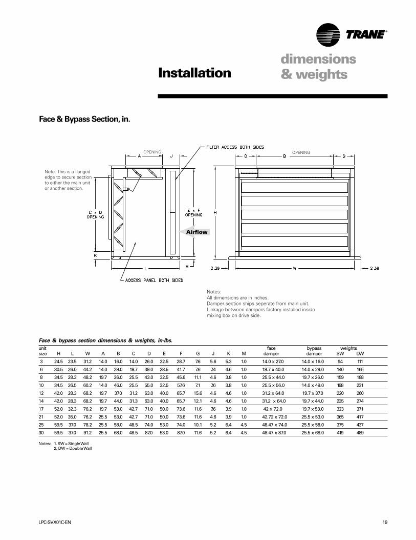
Face & Bypass Section, in.
Face & bypass section dimensions & weights, in-lbs.
unit face bypass weightssize H L W A B C D E F G J K M damper damper SW DW
3 24.5 23.5 31.2 14.0 16.0 14.0 26.0 22.5 28.7 7.6 5.6 5.3 1.0 14.0 x 27.0 14.0 x 16.0 94 111
6 30.5 26.0 44.2 14.0 29.0 19.7 39.0 28.5 41.7 7.6 7.4 4.6 1.0 19.7 x 40.0 14.0 x 29.0 140 165
8 34.5 28.3 48.2 19.7 26.0 25.5 43.0 32.5 45.6 11.1 4.6 3.8 1.0 25.5 x 44.0 19.7 x 26.0 159 188
10 34.5 26.5 60.2 14.0 46.0 25.5 55.0 32.5 57.6 7.1 7.6 3.8 1.0 25.5 x 56.0 14.0 x 49.0 198 231
12 42.0 28.3 68.2 19.7 37.0 31.2 63.0 40.0 65.7 15.6 4.6 4.6 1.0 31.2 x 64.0 19.7 x 37.0 220 260
14 42.0 28.3 68.2 19.7 44.0 31.3 63.0 40.0 65.7 12.1 4.6 4.6 1.0 31.2 x 64.0 19.7 x 44.0 235 274
17 52.0 32.3 76.2 19.7 53.0 42.7 71.0 50.0 73.6 11.6 7.6 3.9 1.0 42 x 72.0 19.7 x 53.0 323 371
21 52.0 35.0 76.2 25.5 53.0 42.7 71.0 50.0 73.6 11.6 4.6 3.9 1.0 42.72 x 72.0 25.5 x 53.0 365 417
25 59.5 37.0 78.2 25.5 58.0 48.5 74.0 53.0 74.0 10.1 5.2 6.4 4.5 48.47 x 74.0 25.5 x 58.0 375 437
30 59.5 37.0 91.2 25.5 68.0 48.5 87.0 53.0 87.0 11.6 5.2 6.4 4.5 48.47 x 87.0 25.5 x 68.0 419 489
Note: This is a flangededge to secure sectionto either the main unitor another section.
OPENING
Notes:All dimensions are in inches.Damper section ships seperate from main unit.Linkage between dampers factory installed insidemixing box on drive side.
OPENING
Airflow
Notes: 1. SW = Single Wall2. DW = Double Wall

20 LPC-SVX01C-EN
Installation
Electric Heat Section
CUSTOMER ELECTRICALCONNECTION LOCATION &SIZE TO BE DETERMINED BYTUTCO
Electric Heat Section Dimensions & Weights, in-lbs.
UnitSize H W A B C D Weight
3 24.5 18.0 12.0 10.4 9.3 12.1 34.0
6 30.5 21.0 16.0 13.6 12.3 8.9 38.0
8 34.5 24.5 16.0 13.6 15.8 9.9 44.0
10 34.5 27.5 20.0 16.0 18.8 11.5 62.0
12 42.0 27.8 20.0 19.0 19.0 13.5 66.0
14 42.0 30.8 20.0 19.0 22.0 13.5 69.0
17 52.0 28.6 20.0 24.9 19.9 7.6 73.0
21 52.0 33.6 20.0 24.9 24.9 7.6 77.0
25 59.5 32.0 20.0 25.3 23.3 7.3 79.0
30 59.5 35.1 20.0 28.3 26.4 4.2 82.0
dimensions& weights

LPC-SVX01C-EN 21
Water Coil Connections left hand
right hand
Note: J = 3.1” on unit sizes 3 and 6= 3.6” on unit sizes 8–21= 4.6” on unit sizes 25 & 30
K = 6.1” on unit sizes 3–21= 8.1” on unit sizes 25 & 30
Installationdimensions& weights
AIR FLOW
AIR FLOW

22 LPC-SVX01C-EN
Water coil connections, in.
left hand connections only right hand connections onlyunit size A B C D A B C D E F G H
one-row coil
3 8 5/8 11 11/16 2 18 5/16 7 7/8 11 1/8 1 3/8 17 5/8 1 11/16 3 11/16 5 3/8 1 1/2
6 11 1/8 14 3/16 2 23 5/16 10 3/8 13 5/8 1 3/8 22 5/8 1 11/16 3 11/16 5 3/8 1 1/2
8, 10 13 5/8 16 11/16 2 28 5/16 12 7/8 16 1/8 1 3/8 27 5/8 1 11/16 3 11/16 5 3/8 1 1/2
12, 14 17 5/16 20 3/8 2 35 13/16 16 11/16 19 13/16 1 3/8 35 1/8 1 1/2 3 7/8 5 3/8 2
17, 21 22 5/16 25 3/8 2 45 13/16 21 11/16 24 13/16 1 3/8 45 1/8 1 1/2 3 7/8 5 3/8 2
25, 30 25 3/8 28 5/8 2 5/8 51 3/8 24 13/16 27 7/8 2 50 13/16 2 4 1/2 6 1/2 2
two-row coil
3 7 5/8 10 13/16 1 3/8 17 8 7/8 12 2 5/8 18 5/16 1 13/16 3 5/8 5 3/8 1 1/2
6 10 13/16 13 7/8 2 22 5/8 10 13/16 13 7/8 2 22 5/8 1 13/16 3 5/8 5 3/8 1 1/2
8, 10 13 5/16 16 3/8 2 27 5/8 13 5/16 16 3/8 2 27 5/8 1 13/16 3 5/8 5 3/8 1 1/2
12, 14 17 20 1/8 2 35 1/8 17 20 1/8 2 35 1/8 1 1/2 3 13/16 5 3/8 2
17, 21 22 25 1/8 2 45 1/8 22 25 1/8 2 45 1/8 1 1/2 3 13/16 5 3/8 2
25, 30 25 1/8 28 3/16 2 51 3/8 25 1/8 28 5/16 2 51 3/8 1 7/8 4 5/8 6 1/2 2 1/2
four-row coil
3 7 5/8 10 13/16 2 5/8 18 5/16 8 7/8 12 2 5/8 18 5/16 4 7 3/16 9 1 1/2
6 10 13/16 13 7/8 2 22 5/8 10 13/16 13 7/8 2 22 5/8 4 7 3/16 9 1 1/2
8, 10 13 5/16 16 3/8 2 27 5/8 13 5/16 16 3/8 2 27 5/8 4 7 3/16 9 1 1/2
12, 14 17 20 1/8 2 35 1/8 17 20 1/8 2 35 1/8 4 7 3/16 9 2
17, 21 22 25 1/8 2 45 1/8 22 25 1/8 2 45 1/8 4 7 3/16 9 2 1/2
25, 30 25 1/8 28 3/16 2 51 3/8 25 1/8 28 5/16 2 51 3/8 4 7 3/16 9 2 1/2
six-row coil
3 7 5/8 10 13/16 2 5/8 18 5/16 8 7/8 12 2 5/8 18 5/16 1 13/16 7 3/16 9 1 1/2
6 10 13/16 13 7/8 2 22 5/8 10 13/16 13 7/8 2 22 5/8 1 13/16 7 3/16 9 1 1/2
8, 10 13 5/16 16 3/8 2 27 5/8 13 5/16 16 3/8 2 27 5/8 1 13/16 7 3/16 9 1 1/2
12, 14 17 20 1/8 2 35 1/8 17 20 1/8 2 35 1/8 1 13/16 7 3/16 9 2
17, 21 22 25 1/8 2 45 1/8 22 25 1/8 2 45 1/8 1 13/16 7 3/16 9 2 1/2
25, 30 25 1/8 28 3/16 2 51 3/8 25 1/8 28 5/16 2 51 3/8 1 13/16 7 3/16 9 2 1/2
eight-row coil
3 7 5/8 10 13/16 2 5/8 18 5/16 8 7/8 12 2 5/8 18 5/16 1 13/16 9 3/8 11 3/16 1 1/2
6 10 13/16 13 7/8 2 22 5/8 10 13/16 13 7/8 2 22 5/8 1 13/16 9 3/8 11 3/16 1 1/2
8, 10 13 5/16 16 3/8 2 27 5/8 13 5/16 16 3/8 2 27 5/8 1 13/16 9 3/8 11 3/16 1 1/2
12, 14 17 20 1/8 2 35 1/8 17 20 1/8 2 35 1/8 1 13/16 9 3/8 11 3/16 2
17, 21 22 25 1/8 2 45 1/8 22 25 1/8 2 45 1/8 1 13/16 9 3/8 11 3/16 2 1/2
25, 30 25 1/8 28 5/16 2 51 3/8 25 1/8 28 5/16 2 51 3/8 1 13/16 9 3/8 11 3/16 2 1/2
Installationdimensions& weights

LPC-SVX01C-EN 23
DX Coil Connections
single circuit coils for unit sizes 3 –10 and horizontal face split coils for unit sizes 12 – 25
right handleft hand
NOTE: DX COIL CONNECTIONS ARE SWEAT STYLE
Single circuit DX coil connections, unit sizes 3 - 10, in.
unit size A B C D (LH) D (RH) G H J K
four-row coil, 3/16” distributor 3 2 3/8 10 5/16 4 5 1/8 7 3/16 1 3/8 5/8 3 1/8 6 1/8
6 2 3/8 17 11/16 4 5 1/8 7 3/16 1 3/8 7/8 3 1/8 6 1/8
8 2 3/8 18 13/16 4 5 1/8 7 3/16 1 3/8 7/8 3 5/8 6 1/8
10 2 1/2 18 3/16 4 5 1/8 7 3/16 1 5/8 7/8 3 5/8 6 1/8
six-row coil, 1/4” distributor 3 2 3/8 11 1 13/16 2 7/8 5 1 3/8 7/8 3 1/8 6 1/8
6 2 3/8 17 11/16 1 13/16 2 7/8 5 1 3/8 7/8 3 1/8 6 1/8
8 2 3/8 19 5/16 1 13/16 2 7/8 5 1 3/8 1 1/8 3 5/8 6 1/8
10 2 1/2 19 1 13/16 2 7/8 5 1 5/8 1 3/8 3 5/8 6 1/8
Note: Single circuit DX coils on unit sizes 3 – 10 have one distributor.
Horizontal face split circuit DX coil connections, unit sizes 8 – 25, in.
unitsize A B C D (LH) D (RH) E F G G1 H H1 J K
four-row coil, 3/16” distributor8 2 3/8 8 1/8 4 5 1/8 7 3/16 17 3/8 22 13/16 1 3/8 1 3/8 5/8 5/8 3 5/8 6 1/8
10 2 3/8 8 1/8 4 5 1/8 7 3/16 14 7/8 22 3/8 1 3/8 1 3/8 7/8 7/8 3 5/8 6 1/8
12, 14 1 7/8 12 5/8 4 5 1/8 7 3/16 19 7/8 31 1/8 1 3/8 1 3/8 7/8 7/8 3 5/8 6 1/8
17, 21 1 7/8 17 5/8 4 5 1/8 7 3/16 25 41 3/8 1 5/8 1 5/8 7/8 7/8 3 5/8 6 1/8
25 1 7/8 18 5/16 4 5 5/16 7 3/16 27 1/2 43 5/16 1 5/8 1 5/8 7/8 7/8 4 5/8 8 1/8
six-row coil, 1/4” distributor
8 2 3/8 8 13/16 1 13/16 2 7/8 5 17 3/8 22 3/8 1 3/8 1 3/8 7/8 7/8 3 5/8 6 1/8
10 2 3/8 13/16 1 13/16 2 7/8 5 14 7/8 22 3/8 1 3/8 1 5/8 7/8 7/8 3 5/8 6 1/8
12, 14 2 3/8 13 1 13/16 2 7/8 5 19 7/8 31 3/8 1 3/8 1 3/8 1 1/8 7/8 3 5/8 6 1/8
17, 21 2 3/8 18 3/16 1 13/16 2 7/8 5 25 42 1 5/8 1 5/8 1 1/8 1 1/8 3 5/8 6 1/8
Installationdimensions& weights
AIR FLOWAIR FLOW

24 LPC-SVX01C-EN
DX Coil Connections
horizontal face split circuit coils for unit size 30
right hand
left hand
NOTE: DX COIL CONNECTIONS ARE SWEAT STYLE
NOTE: DX COIL CONNECTIONS ARESWEAT STYLE
Horizontal face split circuit DX coil connections, unit size 30, in.
A B C D E F Gfour-row coil, 3/16” distributor3 1/8 4 13/16 11 1/8 23 5/8 36 1/8 48 5/8 7/8
six-row coil, 1/4” distributor1 2 5/8 11 7/8 24 3/8 36 7/8 49 3/8 1 3/8
Note: Horizontal face split circuit DX coils on unit size 30 has four distributors.
Installationdimensions& weights
AIR FLOW
AIR FLOW

LPC-SVX01C-EN 25
DX Coil Connections
intertwined coils unit sizes 8 – 30
right hand
left hand
NOTE: DX COIL CONNECTIONS ARE SWEAT STYLE
Intertwined circuit DX coil connections, unit sizes 8 – 30, in.
unit size A B C D E F G H J J1 J2 J3 K K1 K2 K3 L M N P
four-row coil, 3/16” distributor 8 2 3/8 6 3/16 18 3/16 14 1/8 3 3/16 4 11/16 5 5/16 7 5/16 1 3/8 -- 1 3/8 -- 5/8 -- 5/8 -- -- -- -- -10 2 3/8 4 7/8 20 1/8 22 5/8 3 3/16 4 11/16 5 5/16 7 5/16 1 3/8 -- 1 3/8 -- 7/8 -- 7/8 -- -- -- -- --12,14 2 3/8 4 7/8 22 13/16 19 11/16 3 3/16 4 11/16 5 5/16 7 5/16 1 3/8 -- 1 3/8 -- 7/8 -- 7/8 -- -- -- -- --17, 21 2 3/8 4 7/8 17 1/2 14 7/8 3 3/16 4 11/16 5 5/16 7 5/16 1 3/8 1 3/8 1 3/8 1 3/8 5/8 5/8 7/8 5/8 24 7/8 27 3/8 36 1/8 38 5/825 2 3/8 4 7/8 17 1/2 20 3 3/16 4 11/16 5 5/16 7 5/16 7/8 1 3/8 1 3/8 1 3/8 7/8 7/8 7/8 7/8 27 3/8 29 7/8 42 1/2 4530 2 1/2 3 13/16 18 7/8 20 1/8 3 1/8 4 7/8 6 3/16 8 3/16 1 5/8 1 5/8 1 5/8 1 5/8 7/8 7/8 7/8 7/8 27 1/2 28 13/16 43 7/8 45 1/8
six-row coil, 1/4” distributor8 2 3/8 6 3/16 18 5/8 14 7/8 1 2 5/8 3 3/16 5 3/16 1 3/8 -- 1 3/8 -- 7/8 -- 7/8 -- -- -- -- --10 2 3/8 4 7/8 20 1/8 22 5/8 1 2 5/8 3 3/16 5 3/16 1 3/8 -- 1 3/8 -- 7/8 -- 7/8 -- -- -- -- --12,14 2 3/8 4 7/8 23 3/16 19 13/16 1 2 5/8 3 3/16 5 3/16 1 3/8 -- 1 3/8 -- 7/8 -- 1 1/8 -- -- -- -- --17, 21 2 3/8 4 7/8 17 1/2 15 5/16 1 2 5/8 3 3/16 5 3/16 1 3/8 1 3/8 1 3/8 1 3/8 7/8 7/8 7/8 7/8 24 7/8 27 3/8 36 1/2 3925 2 3/8 4 7/8 17 1/2 20 1 2 5/8 3 3/16 5 3/16 1 3/8 1 3/8 1 3/8 1 3/8 7/8 7/8 7/8 7/8 27 3/8 29 7/8 42 1/2 4530 2 1/2 3 13/16 19 11/16 20 7/8 1 2 5/8 6 3/16 8 3/16 1 5/8 1 5/8 1 5/8 1 5/8 1 3/8 1 3/8 1 3/8 1 3/8 27 1/2 28 13/16 44 11/16 45 7/8
Note: DX intertwined coils, on unit sizes 8 – 14 have two distributors. Unit sizes 17 – 30 have four distributors.
Installationdimensions& weights
AIR FLOW
AIR FLOW

26 LPC-SVX01C-EN
Steam Coil Connections
right handleft hand
Steam coil connections, in.
unitsize A B (LH) B (RH) C D E F (LH) F (RH) G G1 H H1 J K
3 4 1/2 10 7/8 7 7/8 1 5/16 2 13/16 -- -- -- 1 -- 1 1/2 -- 3 1/8 6 1/8
6 4 13 3/8 10 3/8 1 5/16 2 1/2 -- -- -- 1 -- 2 -- 3 1/8 6 1/8
8, 10 3 3/16 15 7/8 12 7/8 1 5/16 2 1/2 -- -- -- 1 5/16 -- 2 1/2 -- 3 5/8 6 1/8
12, 14 2 3/8 18 3/16 18 3/16 1 5/16 2 1/2 -- -- -- 1 5/16 -- 3 -- 3 5/8 6 1/8
17, 21 2 3/16 14 7/8 11 7/8 1 5/16 2 1/2 28 37 3/8 34 3/8 1 5/16 1 2 1/2 2 3 5/8 6 1/8
25, 30 2 5/16 15 12 1 5/16 2 1/2 27 13/16 40 1/2 37 1/2 1 5/16 1 5/16 2 1/2 2 1/2 4 5/8 8 1/8Note: Unit sizes 17 – 30 with steam coils are two stacked coils.
Installationdimensions& weights
AIR FLOW AIR FLOW

LPC-SVX01C-EN 27
3
3
3 Ft.
3 Ft.
WARNINGHazardous Voltage w/Capacitors!Disconnect all electric power,including remote disconnects anddischarge all motor start/runcapacitors before servicing.Follow proper lockout/tagoutprocedures to ensure the powercannot be inadvertentlyenergized. For variable frequencydrives or other energy storingcomponents provided by Trane orothers, refer to the appropriatemanufacturer’s literature forallowable waiting periods fordischarge of capacitors. Verifywith an appropriate voltmeterthat all capacitors havedischarged. Failure to disconnectpower and discharge capacitorsbefore servicing could result indeath or serious injury.
Receiving and Handling
Upon delivery, inspect all components forpossible shipping damage. See theReceiving Checklist section for detailedinstructions. Trane recommends leavingunits and accessories in their shippingpackages/skids for protection and ease ofhandling until installation.
Shipping PackagePackaged Climate Changer air handlersship assembled on skids with protectivecoverings over the coil and dischargeopenings. Optional accessory sectionsship attached to one another on aseparate skid for unit sizes except 25 and30. For those sizes, up to two accessorysections may ship on one skid.
Ship-Separate AccessoriesField-installed sensors ship separatelyinside the unit’s main control panel.
Receiving ChecklistComplete the following checklistimmediately after receiving unitshipment to detect possible shippingdamage.����� Inspect individual cartons before
accepting. Check for rattles, bentcarton corners, or other visibleindications of shipping damage.
Installationpre-installationconsiderations
Figure I-PC-1. Top view of Packaged climate changer unit showing recommended
service and code clearances.
Table I-PC-1. Service
Requirements, in. (cm)
Unit Size Dimension A
3 43 (109)6 56 (142)8 59 (150)10 & 12 71 (180)14 79 (201)17 74 (188)21 86 (218)2530
����� If a unit appears damaged, inspect itimmediately before accepting theshipment. Manually rotate the fanwheel to ensure it turns freely. Makespecific notations concerning thedamage on the freight bill. Do notrefuse delivery.
����� Inspect the unit for concealeddamage before it is stored and assoon as possible after delivery.Report concealed damage to thefreight line within the allotted timeafter delivery. Check with the carrierfor their allotted time to submit aclaim.
����� Do not move damaged material fromthe receiving location. It is thereceiver’s responsibility to providereasonable evidence that concealeddamage did not occur after delivery.
����� Do not continue unpacking theshipment if it appears damaged.Retain all internal packing, cartons,and crate. Take photos of damagedmaterial.
����� Notify the carrier’s terminal of thedamage immediately by phone andmail. Request an immediate jointinspection of the damage by thecarrier and consignee.
����� Notify your Trane representative ofthe damage and arrange for repair.Have the carrier inspect the damagebefore making any repairs to the unit.
����� Compare the electrical data on theunit nameplate with the ordering andshipping information to verify thecorrect unit is received.
Installation Preparation
Before installing the unit, consider thefollowing unit location recommendationsto ensure proper unit operation.1. Verify the floor or foundation is level.
Shim or repair as necessary. Toensure proper unit operation, installthe unit level (zero tolerance) in bothhorizontal axes. Failure to level theunit properly can result in condensatemanagement problems, such asstanding water inside the unit.
2. Allow adequate service and codeclearances as recommended in“Service Access” section. Positionthe unit and skid assembly in its finallocation.
3. Consider coil piping and condensatedrain requirements. Allow room forproper ductwork and electricalconnections. Support all piping andductwork independently of the unit toprevent excess noise and vibration.
Service Access
See Table I-PC-1 below and Figure I-PC-1for recommended service and codeclearances.

28 LPC-SVX01C-EN
Step 1: Remove screwsholding hinges tofixed panel nearcoil
Step 3: Swap doors to their oppositesides. Hinges will now belocated on the upstream sideof the fan
Step 2: Repeat Step 1on opposite sideof unit
Step 4: Use self drilling screwsremoved in steps 1 & 2to secure hinges toadjacent upstream panel
pre-installationconsiderationsInstallation
Rigging and Handling
Before preparing the unit for lifting,estimate the approximate center ofgravity for lifting safety. Unit weight maybe unevenly distributed with moreweight in the coil area. Approximate unitweights are given in the Dimensions andWeights section and on the unitnameplate.
Before hoisting the unit into position, usea proper rigging method such as straps,slings, or spreader bars for protectionand safety. Always test-lift the unit (atleast 24 inches) to determine the exactunit balance and stability before hoistingit to the installation location.
WARNINGImproper Unit Lift!Test lift unit approximately 24 inchesto verify proper center of gravity liftpoint. To avoid dropping unit,reposition lifting point if unit is notlevel. Failure to properly lift unit couldresult in death, serious injury, orpossible equipment or property-onlydamage.
Unit LocationRecommendations
When selecting and preparing theinstallation location, follow theserecommendations.1. Consider the unit weight. Reference the
unit weight on the unit nameplate or inthe Dimensions and Weights section.
2. Allow sufficient space forrecommended clearances, accesspanel removal, and maintenanceaccess. Refer to Figure I-PC-1.
3. The installer must provide threadedsuspension rods for ceiling mountedunits. All units must be installed level.
4. Coil piping and condensate drainrequirements must be considered.Allow room for proper ductwork andelectrical connections. Support all pipingand ductwork independently of unit toprevent excess noise and vibration.
Skid Removal
The unit ships on skids that provide forkliftlocations from the front or rear. The skidallows easy maneuverability of the unitduring storage and transportation.Remove the skids before placing the unitin its permanent location.
Remove the skids using a forklift or jack.Lift one end of the unit off of the skids.Vibration isolators for external isolationare field supplied. See Figure I-PC-1 forinstallation recommendations.
Rotating Filter Door Swing
The unit ships with the fillter doors in adownstream configuration. To allow thedoors to swing in an upstreamconfiguration, follow the steps listed in thefigure below.
Figure I-PC-2. Rotating Filter Door Swing

LPC-SVX01C-EN 29
pre-installationconsiderationsInstallation
Fan Discharge Conversion
The LPC Vertical Unit can be ordered infour discharge configurations:Top/Front, Front/Top, Top/Back, and Back/Top Figure I-PC-4. DischargeConfigurations. Field conversions fromone configuration to another can bemade for sizes 8 through 21 by modifyingcertain parts of the cabinet and byrotating the fan. Also, if changing from afront or back discharge to a top dischargeconfiguration, a duct extension will needto be added.For sizes 3 and 6 a new fan assembly willbe needed.There are some differences betweensingle-wall construction cabinets withfiberglass insulation anddouble-wall construction cabinets withfoam insulation that will drive someminor differences in some of the stepsrequired for a field conversion.But overall the basic steps are the samefor both.1. Disconnect power from the unit2. Remove access doors.3. Remove the screws inside the
cabinet along the top of the coil thatsecure the coil to the cabinet roof
4a. If top discharge and no internalisolation remove screws securingduct that connects the fan to the roof
b. If top discharge with internal isolation,duct is not mechanically secured tothe fan so roof & duct can beremoved as one piece.
c. Remove roof5a. If horizontal (front or back) discharge
and no internal isolation, removescrews securing fan housing tocabinet
b. If horizontal (front or back) dischargewith internal isolation loosen andremove j-bolt securing fan housing tocabinet.
c. Remove front and back panel.6. Loosen nuts/bolts securing sliding
motor base in place and loosen nutson belt tensioning bolt.
7. Remove v-belt(s)8. Detach fan from the base and rotate
to the desired discharge position.
Figure I-PC-4. Discharge Configurations
9. It may be necessary to remove andreinstall the fan shaft on the oppositeside depending on the new dischargeposition. Loosen set screws on thefan bearings that hold the shaft inplace. Loosen set screw holding fanin place. Remove shaft from the fanand reinstall so that the driven end ison the opposite side.
10. Reattach fan to the base
11. Reattach v-belt, tighten, and securesliding motor base in place. Becausethe distance between the motor shaftand the fan shaft may change, it maybe necessary to purchase a new v-belt.
12. Cut a hole in the discharge panel forthe air discharge. For double wallunits cover the exposed foaminsulation at the inside edges of thehole using the insulation coverchannels installed on the otherdischarge panel.
30 LPC-SVX01C-EN
pre-installationconsiderationsInstallation
Pre-Installation Checklist
Complete the following checklist beforebeginning unit installation.
����� Verify the unit size and tagging withthe unit nameplate.
����� Make certain the floor or foundationis level, solid, and sufficient to supportthe unit and accessory weights. Seethe Dimensions and Weights section.Level or repair the floor beforepositioning the unit if necessary.
����� Allow minimum recommendedclearances for routine maintenanceand service. Refer to unit submittalsfor dimensions.
����� Allow one and one half fan diametersabove the unit for the dischargeductwork.
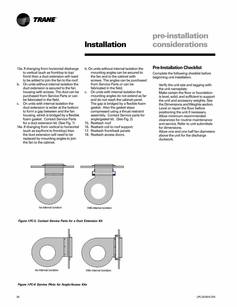
13a. If changing from horizontal dischargeto vertical (such as front/top to top/front) then a duct extension will needto be added to join the fan to the roof.
b. On units without internal isolation theduct extension is secured to the fanhousing with screws. The duct can bepurchased from Service Parts or canbe fabricated in the field.
c. On units with internal isolation theduct extension is wider at the bottomto form a gap between and the fanhousing, which is bridged by a flexiblefoam gasket. Contact Service Partsfor a duct extension kit. (See Fig. 1)
14a. If changing from vertical to horizontal(such as top/front to front/top) thenthe duct extension will need to bereplaced by mounting angles to jointhe fan to the cabinet.
b. On units without internal isolation themounting angles can be secured tothe fan and to the cabinet withscrews. The angles can be purchasedfrom Service Parts or can befabricated in the field.
c. On units with internal isolation themounting angles do not extend as farand do not reach the cabinet panel.The gap is bridged by a flexible foamgasket. Also the gasket stayscompressed using a thrust restraintassembly. Contact Service parts forangle/gasket kit. (See Fig. 2)
15. Reattach roof16. Reattach coil to roof support.17. Reattach front/back panels18. Reattach access doors.
Figure I-PC-5. Contact Service Parts for a Duct Extension Kit
Figure I-PC-6 Service PArts for Angle/Access Kits

LPC-SVX01C-EN 31
this connection to rigid ductwork.
Duct turns and transitions must be madecarefully to minimize air friction losses.Avoid sharp turns and use splitters orturning vanes when elbows are neces-sary. Make turns in the same direction ofrotation of the fan. Discharge ductworkshould run in a straight line, unchanged insize or direction, for at least a distance of1-1/2 fan diametersCondensate DrainConnections
The main drain line and the trap must bethe same size as the drain connection.Refer to Table I-MR-1 for drain line sizes.Refer to Figure I-MR-1 for a guide to trapsizing.
Drain traps must be primed. If they arenot, the trap is essentially non-existentand the drain will likely overflow.
Plug or trap the auxiliary drain connec-tion, if applicable. If the auxiliary drainconnection is left open, air can be drawnin through the opening. This drawn in aircan cause moisture carryover.
All drain lines downstream of the trapmust flow continuously downhill. Ifsegments of the line are routed uphill, thiscan cause the drain line to becomepressurized. With a pressurized drainline, the trap can back up into the drainpan, causing it to overflow.
See Figure I-MR-1 for drain trap recom-mendations.
CAUTIONWater Damage!Failure to make adequate condensatepiping may result in water damage tothe equipment or building.
mechanicalrequirementsInstallation
Duct Connections
WARNINGHazardous Voltage w/Capacitors!Disconnect all electric power,including remote disconnects anddischarge all motor start/runcapacitors before servicing. Followproper lockout/tagout procedures toensure the power cannot beinadvertently energized. Verify with anappropriate voltmeter that allcapacitors have discharged. Failure todisconnect power and dischargecapacitors before servicing couldresult in death or serious injury.
Install all air ducts according to theNational Fire Protection Associationstandards for the “Installation of AirConditioning and Ventilation Systemsother than Residence Type (NFPA 90A)and Residence Type Warm Air Heatingand Air Conditioning Systems (NFPA90B).
For units without internal isolation, inletand discharge air duct connections to theunit should be made with a flexiblematerial minimizing noise and vibration.Typically, about three inches is needed forthis connection to rigid ductwork.
For units with internal isolation, flexiblematerial is not required on the inlet anddischarge air duct connections.
Inlet and discharge air duct connections tothe unit should be made with a flexiblematerial minimizing noise and vibration.Typically, about three inches is needed for
Figure I-MR-1. Recommended drain trap
installation for draw-thru units.
Table I-MR-1. Condensate Piping Sizes
Unit Size 3 6 8 10 12 14 17 21 25 30Main Drain (in) 0.75 0.75 1.00 1.00 1.00 1.00 1.00 1.00 1.25 1.25Main Drain (cm) 1.905 1.905 2.54 2.54 2.54 2.54 2.54 2.54 3.175 3.175Auxiliary Drain (in.) 0.75 0.75 N/A N/A N/A N/A N/A N/A N/A N/AAuxiliary Drain (cm) 1.905 1.905 N/A N/A N/A N/A N/A N/A N/A N/A
Coil Connections
Hydronic CoilsHydronic coil options are either one, two,four, six or eight-row coils with highefficiency Delta-Flo™ fins. Aluminum finsare mechanically bonded to ½ inch O.D.seamless copper tubes. All coils arespecifically designed and circuited forchilled and hot water use only. All coilsare pressure tested at 450 psi. Threadedconnections are standard.
Proper installation and piping is neces-sary to enure satisfactory coil operationand prevent operational damage. Waterinlet and outlet connections protrudethrough the coil access panel. Followstandard piping practices when piping tothe coil.
Steam CoilsPackaged Climate Changer units fittedwith steam coils have labeled holes forpiping penetrations. Check that the coil isinstalled correctly and that the unitinstallation agrees with the submittals.Refer to Figure I-MR-2 for typical steamcoil piping.
H = 1” Of Length for Each 1” Of Negative Pressure+ 1” Additional
J = 1/2 of HL = H + J + Pipe Dia. + Insulation

32 LPC-SVX01C-EN
mechanicalrequirementsInstallation
Coil Connection RecommendationsFollow these recommendations toprevent possible damage when makingcoil connections:1. Install a ½”15 swing-check vacuum
breaker in the unused condensatereturn connection at the top of thecoil. Install this vacuum breaker asclose to the coil as possible.
2. Vent the vacuum breaker to theatmosphere or pipe it to the returnmain at the discharge side of thesteam trap.
Note: A vacuum breaker is mandatorywhen the coil is controlled by a modulat-ing steam supply or two-position (on/off)automatic steam supply valve.
WARNINGHazardous Pressures!
If a heat source is required to raisethe tank pressure during removal ofrefrigerant from cylinders, use onlywarm water or heat blankets to raisethe tank temperature. Do not exceeda temperature of 150°F. Do not, underany circumstances apply directflame to any portion of the cylinder.Failure to follow these safety pre-cautions could result in a violent ex-plosion, which could result in deathor serious injury.
The condensate return line must bepiped full size of the condensate trapconnection, except for a short nipplescrewed directly into the coil headerscondensate return trapping. Do not bushor reduce the coil return tapping size.
Proper Steam Trap InstallationProper steam trap selection andinstallation is necessary for satisfactorycoil performance and service life. Forinstallation, use the following steps:1. Install the steam trap discharge 12
inches below the condensate returnconnection to provide sufficient headpressure to overcome trap lossesand ensure complete condensateremoval. Use float and themostatictraps with atmospheric pressuregravity condensate return, withautomatic controls or when there is apossibility of low pressure steam.
Float and thermostatic traps arerecommended because gravity drainand continuous discharge operation.
2. Trap each coil separately to preventholding up condensate in one ormore of the coils.
3. Install strainers as close as possibleto the inlet side of the trap.
4. Use a V-Port modulating valve toobtain gradual modulation of the coilsteam supply.
5. Do not modulate systems withoverhead or pressurized returnsunless the condensate is drained bygravity into a receiver, vented toatmosphere, and returned to thecondensate pump.
Figure I-MR-2. Typical Piping for Steam Coils
Code of System Components in Piping Diagram
FT Float and thermostatic steam trapBT Bucket steam trapGV Gate valveOV Automatic two-position (on-off) control valveTV Automatic three-way control valveVB Vacuum breakerCV Check valveST StrainerAV Automatic or manual air vent
6. Slowly turn the steam on full for atleast ten minutes before opening thefresh air intake on units with fresh airdampers.
7. Pitch all supply and return steampiping down 1-inch per 10 feet in thedirection of the steam or condensateflow.
8. Do not drain the steam mains ortake-offs through the coils. Drain themains ahead of the coil through asteam trap to the return line.
9. Assure continuous condensateremoval. Overhead returns requireone psig of pressure at the steamtrap discharge for each two feet ofelevation.

LPC-SVX01C-EN 33
• Moisture-indicating sight glass: Install amoisture-indicating sight glass in theliquid line between the expansion valveand filter drier. The sight glass should besized to match the size of the liquid line.
• Filter drier: Install a properly sized liquidline filter-drier upstream from theexpansion valve and as close to theevaporator coil as possible. Select thefilter-drier for a maximum pressure dropof 2 psi at the design condition.
Manual, ball-type shutoff valves on eitherside of the filter drier allows replacementof the core without evacuating the entirerefrigerant charge.
• Access port: The access port allows theunit to be charged with liquid refrigerantand is used to determine subcooling. Thisport is usually a Schraeder valve with acore.
• Solenoid valve: If required by thecompressor unit, install the solenoidvalve between the filter drier and sightglass.
CAUTIONValve Damage!Disassemble the thermal expansionvalve before completing the brazingconnections. If necessary, wrap thevalve in a cool wet cloth while brazing.Failure to protect the valve from hightemperatures may damage internalcomponents.
Figure I-MR-3. Refrigerant Coil with Packed Elbow
Distributor
Coil
PanelPerforated Plate(Packed Elbow)
Cut herefor piping
mechanicalrequirementsInstallation
Refrigerant Coil Piping
Units that are UL listed shall nothave refrigerant temperatures andpressures exceeding that listed onthe unit nameplate.
For unit-installed refrigerant coils, packedelbows are provided. Make pipe connec-tions as shown in Figure I-MR-2.
Note: DX coils ship dehydrated andcharged with a dry air holding charge. Toprevent leaks and system contamination,do not break the seal until the coil isinstalled. All liquid lines have a 5/8”process tube attached. Use only a pipecutter to cut the process tube.
Ensure the coil is installed correctly withairflow in the same direction as indicatedon the coil nameplate or casing (fieldinstalled coils). The suction connectionmust be at the bottom of the suctionheader.
Follow accepted refrigeration pipingpractices and safety precautions fortypical refrigerant coil piping and compo-nents. Specific recommendations areprovided with the highside components,including instructions for pressure-testing,evacuation, and system charging. Followthe general recommendations forcomponent selection and line sizingbelow. Leak test the entire refrigerantsystem after all piping is complete.
Charge the unit according to approximateweight requirements, operating pres-sures and superheat/subcooling mea-surements. Adjust the thermal expansionvalve setting if necessary.
General Refrigerant PipingRecommendations
Note: Refer to the note on page two ofthis manual regarding the handling ofrefrigerants. Line Sizing: Properly sizingthe liquid line is critical to a successfulapplication. If provided, use the liquid linesize recommended by the manufacturerof the compressor unit. The selected tubediameter must be as small as possible,while still providing at least 5°F [2.7°C] ofsubcooling at the expansion valvethroughout the operating envelope.
Routing: Install the liquid line with a slightslope in the direction of flow so that it canbe routed with the suction line. Minimizetube bends and reducers because theseitems tend to increase pressure drop andreduce subcooling at the expansionvalve.
Insulation: The liquid line is generallywarmer than the surrounding air, so itdoes not require insulation.
Components: Liquid-line refrigerantcomponents necessary for a successfuljob include an expansion valve, mois-ture-indicating sight glass, filter drier,manual ball shutoff valves, access port,and possibly a solenoid valve. Positionthese components as close to theevaporator as possible.
• Thermal expansion valve (TEV): Selectthe TEV based on the actual evaporatorcapacity, considering the full range ofloadings. Verify that the valve willsuccessfully operate at the lightest loadcondition, considering if hot gas bypass isto be used. For improved modulation,choose a TEV with balanced port con-struction and an external equalizerconnection. The valve must be designedto operate against a back pressure of 20psi higher than actual evaporatorpressure. Install the TEV directly on thecoil liquid connection(distributor provided).
The remote expansion-valve bulb shouldbe firmly attached to a straight, well-drained, horizontal section of the suctionline. The external equalizer line should beinserted downstream of the remote bulb.

34 LPC-SVX01C-EN
mechanicalrequirementsInstallation
Suction LineLine sizing: Properly sizing the suction lineis critical for ensuring that the oil returnsto the compressor throughout the systemoperating envelope. If provided, use thesuction line size(s) recommended by themanufacturer of the compressor unit. Theselected tube diameter(s) must maintainadequate refrigerant velocities at alloperating conditions.
Routing: To prevent residual or con-densed refrigerant from “free-flowing”toward the compressor, install the suctionline so it slopes slightly — 1 inch per 10feet of run [1 cm per 3 m] — toward theevaporator. Avoid putting refrigerantlines underground. Refrigerant condensa-tion, installation debris inside the line,service access, and abrasion/corrosioncan quickly impair system reliability.
Insulation: After operating the systemand testing all fittings and joints to verifythe system is leak-free, insulate thesuction lines to prevent heat gain andunwanted condensation.
Components: Installing the suction linerequires field installation of thesecomponents: an access port and possiblya suction filter. Position them as close tothe compressor as possible.
• Access port: The access port is used todetermine suction pressure and adjustthe TEV. It should be located near theexternal equalizer line connection. Thisport is usually a Schraeder valve with acore.
• Suction filter: If required by the com-pressor unit, a replaceable-core suctionfilter is installed as close to the compres-sor unit as possible. Adding manual, ball-type shutoff valves upstream anddownstream of the filter simplifiesreplacement of the filter core.
CAUTIONHigh Temperatures While Brazing!Disassemble the thermal expansionvalve before completing the brazingconnections. If necessary, wrap thevalve in a cool wet cloth while brazing.Failure to protect the valve from hightemperatures may result in damageto internal components.
LPC-SVX01C-EN 35
electricalrequirements
Unit Wiring Diagrams
Specific unit wiring diagrams areprovided on the inside of the controlpanel door. Use these diagrams forconnections or trouble analysis.
WARNINGHazardous Voltage w/Capacitors!Disconnect all electric power,including remote disconnects anddischarge all motor start/runcapacitors before servicing. Followproper lockout/tagout procedures toensure the power cannot beinadvertently energized. Verify with anappropriate voltmeter that allcapacitors have discharged. Failure todisconnect power and dischargecapacitors before servicing couldresult in death or serious injury.
Supply Power Wiring
It is the installer’s responsibility to providepower supply wiring to the unit. Wiringshould conform to NEC and all applicablecode requirements. When units areordered without controls, the contractormust also furnish an on/off switch,thermostat, and a fused disconnectswitch in compliance with national andlocal electrical codes.
Bring supply wiring through the knockoutin the unit control box. Connect the threephase wires to the power terminal blockor the non-fused disconnect switch in thecontrol box terminals. Refer to specificwiring diagrams and fuse information inthe unit’s control panel.
Refer to unit specific wiring diagrams forspecific wiring connections. Locate unitwiring diagrams on the inside of thecontrol box cover. Refer to the unitnameplate for unit specific electricalinformation, such as voltage, minimumcircuit ampacity (MCA), and maximumfuse size (MFS).
CAUTIONUse Copper Conductors Only!Unit terminals are not designed toaccept other types of conductors.Failure to use copper conductors mayresult in equipment damage.
CautionMotor Winding Damage!Do not use a megohm meter or applyvoltage greater than 50 DVC to acompressor motor winding while it isunder a deep vacuum. Voltagesparkover may cause damage to themotor windings.
Electrical GroundingRestrictions
All sensor and input circuits are normallyat or near ground (common) potential.When wiring sensors and other inputdevices to the Tracer AH540 controller,avoid creating ground loops withgrounded conductors external to the unitcontrol circuit. Ground loops can affectthe measurement accuracy of thecontroller.
All input/output circuits (except isolatedrelay contacts and optically isolatedinputs) assume a grounded source, eithera ground wire at the supply transformerto control panel chassis, or an installersupplied ground.
Installation
Note: Do not connect any sensor or inputcircuit to an external ground connection.
The installer must provide interconnec-tion wiring to connect wall mounteddevices such as a zone sensor module.Refer to the unit wiring schematic forspecific wiring details and point-to-pointwiring connections. Dashed lines indicatefield wiring on the unit wiring schematics.All interconnection wiring must conformto NEC Class 2 wiring requirements andany state and local requirements. Referto Table 1 for the wire size range andmaximum wiring distance for eachdevice.
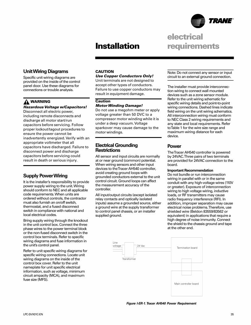
Power
The Tracer AH540 controller is poweredby 24VAC. Three pairs of two terminalsare provided for 24VAC connection to theboard.
Important RecommendationDo not bundle or run interconnectionwiring in parallel with or in the sameconduit with any high-voltage wires (110Vor greater). Exposure of interconnectionwiring to high voltage wiring, inductiveloads, or RF transmitters may causeradio frequency interference (RFI). Inaddition, improper separation may causeelectrical noise problems. Therefore, useshielded wire (Beldon 83559/83562 orequivalent) in applications that require ahigh degree of noise immunity. Connectthe shield to the chassis ground and tapeat the other end.
Figure I-ER-1. Tracer AH540 Power Requirement
Termination board
Main controller board
Transformer
Line voltage 24 Vac

36 LPC-SVX01C-EN
electricalrequirementsInstallation
Table ER-2. LPC Electric Heat kW Limits, Min./Max
unit size
voltage 3 6 8 10 12 14 17 21 25 30208/60/1 6/9 6/18 7/18 8/28 N/A N/A N/A N/A N/A N/A230/60/1 6/11 6/20 7/20 8/30 N/A N/A N/A N/A N/A N/A277/60/1 6/13 6/24 7/24 8/38 N/A N/A N/A N/A N/A N/A208/60/3 6/13 6/26 7/28 8/41 10/50 12/50 14/50 17/50 20/47 20/41230/60/3 6/13 6/26 7/32 8/41 10/53 12/59 14/59 17/59 20/56 20/50460/60/3 6/13 6/24 7/32 8/44 10/53 12/63 14/75 17/95 20/95 20/120575/60/3 6/13 6/26 7/34 8/44 10/53 12/63 14/75 17/95 20/95 20/120380/50/3 6/13 6/26 7/32 8/44 10/53 12/63 14/75 17/95 20/95 20/95415/50/3 6/13 6/26 7/32 8/44 10/53 12/63 14/75 17/95 20/95 20/95minimum air flowcfm 1050 2100 2800 3500 4200 4900 5950 7350 8750 10,500
Note:1. Heaters available in the following kW increments:
6 14 26 44 71 1107 15 28 47 75 1158 16 30 50 79 1209 17 32 53 83
10 18 34 56 8711 20 36 59 9112 22 38 63 9513 24 41 67 100
1. Units drawing less than 100 amps are available with or without door interlocking disconnect. Units drawing more than 100 amps are not available with door interlocking disconnect.2. Units drawing less than 48 amps are available with or without line fusing. Units drawing greater than 48 amps have line fusing as standard.3. Units with electric heat must not be run below the minimum cfm listed above.
Table ER-1. Electric heat voltage
unit heatervoltage voltage
208 208
230 240
277 277
460 480
575 600
380 380
415 415
Useful Formulas:
Single Phase Heater Amps = (kW x 1000)/ Voltage
Three Phase Heater Amps = (kW x 1000)/ (Voltage x 1.73)
Minimum Circuit Ampacity = MCAMCA = 1.25 x (heater amps + motor FLA)
Maximum Fuse Size or Maximum Overcurrent Protection = MFSMFS = (2.25 x motor FLA) + heater amps
kW = (Air Flow x Delta T) / KDelta T = (kW x K) / Air FlowK = 3145 (English)K = 824.7 (SI)
HACR (Heating, Air-Conditioning andRefrigeration) type circuit breakers arerequired in the branch circuit wiring for allfan-coils with electric heat.
SeeTables ED- 3 through ED-6 for motorFLA’s
Select a standard fuse size or HACR typecircuit breaker equal to the MCA.Use the next larger standard size if theMCA does not equal a standard size.
Standard fuse sizes are:15, 20, 25, 30, 35, 40, 45, 50, 60 amps

LPC-SVX01C-EN 37
electricalrequirementsInstallation
Table ER-3. Motor electrical characteristics & motor/VFD weight, lbs.
utilization motor motor VFD VFDhp voltage FLA LRA RPM weight frame size line input weight0.5 208/60/1 3.7 17.4 1725 23 56
230/60/1 3.6 17.3277/60/1 3.2 14.5 1725 23 56208/60/3 2.1 15 1725 21 56230/60/3 2.2 13 1725 23 56460/60/3 1.1 6.5
0.75 208/60/1 5 28.9 1725 33 56230/60/1 4.9 29277/60/1 4.2 29 1725 33 56208/60/3 3.1 20.5 1725 24 56230/60/3 3 20 1725 27 56460/60/3 1.5 10
1 208/60/1 5.3 32.9 1725 35 56230/60/1 5 33277/60/1 4.1 30 1725 35 56208/60/3 3.1 20.3 1725 33 56 6.3 27230/60/3 2.8 20 6.3 27460/60/3 1.4 10 2.5 27575/60/3 1.1 8 1725 34 56 2.3 31400/50/3 2.1 16.8 1450 39 56 2.8 27
1.5 208/60/3 5 34.4 1740 6.3 27230/60/3 4.6 34 6.3 27460/60/3 2.3 17 2.5 27575/60/3 1.65 12.6 1740 39 56 2.3 31400/50/3 2.5 19.7 1450 40 56 2.8 27
2 208/60/3 5.9 42.3 7.3 27230/60/3 5.6 42 1725 7.3 27460/60/3 2.8 21 3.4 27575/60/3 2.2 16.8 1740 45 56 2.6 31400/50/3 3.6 31.6 1450 56 56 3.8 27
3 208/60/3 8.7 64.7 10.4 31230/60/3 8 64 1725 10.4 31460/60/3 4 32 4.8 27575/60/3 3.2 25.6 1725 56 56 3.8 31400/50/3 5.5 44.6 1450 74 182-4T 5.3 27
5 208/60/3 14 91.8 16.8 31230/60/3 13.2 91 1740 16.8 31460/60/3 6.6 45.5 8.3 31575/60/3 5.3 36.4 1740 74 182-4T 5.9 31400/50/3 9.5 68.1 1450 113 213-5T 9.1 31
7.5 208/60/3 22.2 139.4 23.8 76230/60/3 21.6 138.8 1760 23.8 76460/60/3 10.8 69.4 10.6 31575/60/3 8 49 1760 113 213-5T 9.2 31400/50/3 13.5 89.5 1450 129 213-5T 15.2 31
10 208/60/3 28 180 32.2 76230/60/3 28 180 1760 32.2 76460/60/3 14 90 14.2 31575/60/3 11 72 1760 131 213-5T 11.1 31400/50/3 18.5 148.7 1450 167 254T 24.0 76
15 208/60/3 40.6 301 48.3 84230/60/3 40.6 301 1760 48.3 84460/60/3 20.3 150.5 21.0 76575/60/3 16.2 120 1760 162 254T 16.6 76400/50/3 23 148 1465 235 254-6T 24.0 76
20 208/60/3 61 298 1760 198 254-6T 61.9 84230/60/3 50 300 1760 235 254-6T 61.9 84460/60/3 25 150 27.6 76575/60/3 20 135 1760 242 254-6T 21.4 76
38 LPC-SVX01C-EN
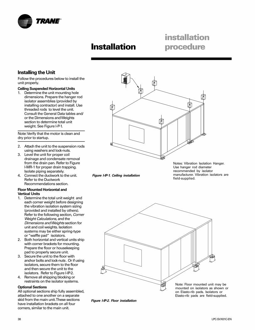
installationprocedureInstallation
Installing the Unit
Follow the procedures below to install theunit properly.
Ceiling Suspended Horizontal Units1. Determine the unit mounting hole
dimensions. Prepare the hanger rodisolator assemblies (provided byinstalling contractor) and install. Usethreaded rods to level the unit.Consult the General Data tables and/or the Dimensions and Weightssection to determine total unitweight. See Figure I-P-1.
Note: Verify that the motor is clean anddry prior to startup.
2. Attach the unit to the suspension rodsusing washers and lock-nuts.
3. Level the unit for proper coildrainage and condensate removalfrom the drain pan. Refer to FigureI-MR-1 for proper drain trapping.Isolate piping separately.
4. Connect the ductwork to the unit.Refer to the DuctworkRecommendations section.
Floor Mounted Horizontal andVertical Units1. Determine the total unit weight and
each corner weight before designingthe vibration isolation system sizing(provided and installed by others).Refer to the following section, CornerWeight Calculations, and theDimensions and Weights section forunit and coil weights. Isolationsystems may be either spring-typeor “waffle pad” isolators.
2. Both horizontal and vertical units shipwith corner brackets for mounting.Prepare the floor or housekeepingpad to properly secure unit.
3. Secure the unit to the floor withanchor bolts and lock-nuts . Or if usingisolators, secure them to the floorand then secure the unit to theisolators. Refer to Figure I-IP-2.
4. Remove all shipping blocking orrestraints on the isolator systems.
Optional SectionsAll optional sections ship fully assembled,attached to one another on a separateskid from the main unit. These sectionshave installation brackets on all fourcorners, similar to the main unit.
Figure I-IP-2. Floor installation
Figure I-IP-1. Ceiling installation
Notes: Vibration Isolation Hanger.Use hanger rod diameterrecommended by isolatormanufacturer. Vibration isolators arefield-supplied.
Note: Floor mounted unit may bemounted on isolators as shown oron Elasto-rib pads. Isolators orElasto-rib pads are field-supplied.

LPC-SVX01C-EN 39
installationprocedureInstallation
LPC Unit Corner WeightCalculations
Calcute model LPC corner weights toensure you size isolators correctly.Remember, units are not internallyisolated and require external isolatorsprovided at installation.
Before calculating the corner weights,you must first calculate the total unitweight. Add the coil, motor, and controlbox weights to the main unit weight toget the total unit weight. Weights arelisted in the Dimensions & Weightssection of this manual.
ExampleThis example uses a size 8 horizontalunit, with a right-hand motor/drive &control box.
Note: Include the wet coil weight. Motor/drive control box always = 9 lbs.
1. Calculate total LPC operating weight:component weight, lbs.main unit 240motor, 460/60/3, ½ hp 438-row hydronic coil 212.2control box 9
Total operating weight = 504.2
Reference Figure I-IP-1 for a visualexplanation of the following steps.
2. Calculate the “leaving air side” cornerweights, labeled C & D in graphic.• Divide the main unit weight by 4 to
get main unit corner weight:240 ÷ 4 = 60 lbs.
• Divide the motor weight by 2 to getthe 2 corners. Add to the main unitcorner weight to get the total cornerweight: 43 ÷ 2 = 21.5 + 60 = 81.5 lbs.
Note: To get the total corner weight youmust add the motor/drive control boxweight to the correct unit side. See step 4.
3. Calculate the “entering air side”corner weights, labeled A & B in thegraphic.• Divide the coil weight by 2 to get the
2 coil weight corners of the enteringair side. Add to the main unit cornerweight of the entering air side: 212.2÷ 2 = 106.1 lbs. + 60 lbs. = 166.1 lbs.
Note: To get the total corner weight youmust add the motor/drive control boxweight to the correct unit side. See step 4.
4. Add the motor/drive control boxweight to the correct unit side.The unit can have the motor/drive controlbox on either the right or left-hand side.Verify this by inspecting the unit orreferencing the unit model number,digit 12 .
In this example (right-hand motor/drive),we will add the control box weight to theleaving air side, corner weight C: 81.5 lbs+ 9 lbs. = 90.5 lbs.
Figure I-IP-1. Corner weight calculation example: size 8 horizontal LPC with a
right-hand motor/drive & control box.
Corner D:main unit ÷ 4 = 60 lb.motor ÷ 2 = 21.5 lb.total corner D = 81.5 lb.
Corner B:main unit ÷ 4 = 60 lb.coil ÷ 2 = 106.1 lb.total corner B = 166.1 lb.
Corner C:main unit ÷ 4 = 60 lb.motor ÷ 2 = 21.5 lb.control box = 9 lb.total corner C = 90.5 lb.
Corner A:main unit ÷ 4 = 60 lb.coil ÷ 2 = 106.1 lb.total corner A = 166.1 lb. A
B
C
D
control box

40 LPC-SVX01C-EN
installationprocedureInstallation
Attaching optional sections tothe model LPC
Note: Gasketing is not required on thisequipment. The Packaged ClimateChanger was designed and tested to beused without gasketing.
Note: All screws, nuts, & bolts required forinstallation are field-provided.
Step 1.
Connect modules to flange on top of unit.
Step 2.
Use the flange on both sides of the unit toconnect modules.
main unit

LPC-SVX01C-EN 41
installationprocedureInstallation
Step 3.
Line up the holes on the unit and moduleand attach together using a #10 - 16 x 0.5inch screw.
Step 4.
Line up the corner brackets on themodule being joined.
Step 5.
Attach the corner brackets using a boltand nut.
Note: Gasketing is not required on theseunits. The Packaged Climate Changer isdesigned and tested to be used withoutgasketing. All screws, nuts, and boltsrequired for installation are field supplied.

42 LPC-SVX01C-EN
4. To install the zone sensor module to astandard junction box:
a. Level and install a 2“ x 4” junctionbox (installer supplied) vertically onthe wall.
b. Pull the control wires through thecutout. Attach the module to the wallusing the screws provided.
5. Strip the insulation on theinterconnection wires back 0.25 inchand connect to TB1. Screw down theterminal blocks.
6. Replace the zone sensor cover andadjustment knob.
If installing a Tracer AH540 zone sensor,see the Tracer Summit Communicationsection for more information.
LPC M-Series
LPC M-Series
installationprocedureInstallation
Installing Wall MountedControls
Wall mounted zone sensors ship taped tothe control box.
Position the controller on an inside wallthree to five feet above the floor and atleast 18 inches from the nearest outsidewall. Installing the controller at a lowerheight may give the advantage ofmonitoring the temperature closer to thezone, but it also exposes the controller toairflow obstructions. Ensure that air flowsfreely over the controller.
Before beginning installation, follow thewiring instructions below. Also, refer tothe unit wiring schematic for specificwiring details and point connections.
Wiring InstructionsAvoid mounting the controller in an areasubject to the following conditions:• Dead spots, such as behind doors or in
corners that do not allow free aircirculation.
• Air drafts from stairwells, outsidedoors, or unsectioned hollow walls.
• Radiant heat from the sun, fireplaces,appliances, etc.
• Airflow from adjacent zones or otherunits.
• Unheated or uncooled spaces behindthe controller, such as outside walls orunoccupied spaces.
• Concealed pipes, air ducts, or chimneysin partition spaces behind the controller.
Zone Sensor Installation
Follow the procedure below to install thezone sensor module.1. Note the position of the setpoint
adjustment knob and gently pry theadjustment knob from the coverusing the blade of a smallscrewdriver.
2. Insert the screwdriver blade behindthe cover at the top of the moduleand carefully pry the cover awayfrom the base.
3. To install the zone sensor modulewithout a junction box (directly to thewall):
a. Using the module base as atemplate, mark the the rectangularcutout for the control wiring andmodule installation holes. Ensure thebase is level.
b. Set the base aside and make thecutout. Then, drill two 3/16” diameterholes approximately one-inch deep.Insert and fully seat the plastic anchors.
c. Pull the control wires through thecutout and attach the module to thewall using the screws provided.
Figure I-IP-3. Wall mounted zone sensor dimensions.
VIEW WITH COVER REMOVED(NOT TO SCALE)
Table ER-4 Zone Sensor Maximum Wiring
Distances, ft (m)
Wire Size Range Max. Wiring Distance16 - 22 AWG 200 (60.96)
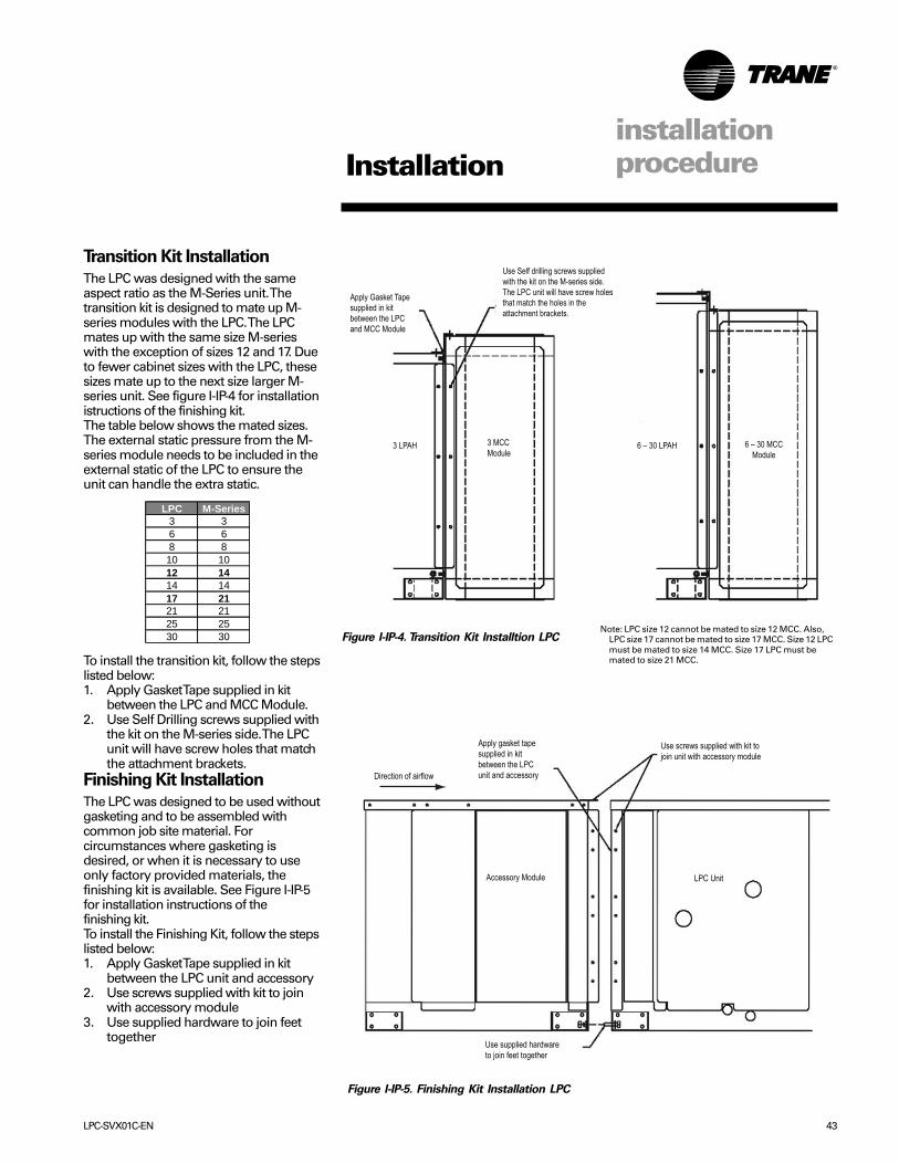
LPC-SVX01C-EN 43
Transition Kit Installation
The LPC was designed with the sameaspect ratio as the M-Series unit. Thetransition kit is designed to mate up M-series modules with the LPC. The LPCmates up with the same size M-serieswith the exception of sizes 12 and 17. Dueto fewer cabinet sizes with the LPC, thesesizes mate up to the next size larger M-series unit. See figure I-IP-4 for installationistructions of the finishing kit.The table below shows the mated sizes.The external static pressure from the M-series module needs to be included in theexternal static of the LPC to ensure theunit can handle the extra static.
To install the transition kit, follow the stepslisted below:1. Apply Gasket Tape supplied in kit
between the LPC and MCC Module.2. Use Self Drilling screws supplied with
the kit on the M-series side. The LPCunit will have screw holes that matchthe attachment brackets.
Finishing Kit Installation
The LPC was designed to be used withoutgasketing and to be assembled withcommon job site material. Forcircumstances where gasketing isdesired, or when it is necessary to useonly factory provided materials, thefinishing kit is available. See Figure I-IP-5for installation instructions of thefinishing kit.To install the Finishing Kit, follow the stepslisted below:1. Apply Gasket Tape supplied in kit
between the LPC unit and accessory2. Use screws supplied with kit to join
with accessory module3. Use supplied hardware to join feet
together
Direction of airflow
Accessory Module LPC Unit
Use supplied hardware to join feet together
Apply gasket tapesupplied in kitbetween the LPCunit and accessory
Use screws supplied with kit tojoin unit with accessory module
installationprocedureInstallation
Figure I-IP-4. Transition Kit Installtion LPC
Figure I-IP-5. Finishing Kit Installation LPC
3 LPAH 3 MCCModule
6 – 30 LPAH 6 – 30 MCCModule
Apply Gasket Tapesupplied in kitbetween the LPCand MCC Module
Use Self drilling screws suppliedwith the kit on the M-series side.The LPC unit will have screw holesthat match the holes in the attachment brackets.
Note: LPC size 12 cannot be mated to size 12 MCC. Also,LPC size 17 cannot be mated to size 17 MCC. Size 12 LPCmust be mated to size 14 MCC. Size 17 LPC must bemated to size 21 MCC.
LPC M-Series3 36 68 810 1012 1414 1417 2121 2125 2530 30

44 LPC-SVX01C-EN
pre-startuprequirementsInstallation
Wire CharacteristicsController communication-link wiringmust be low capacitance, 18-gage,shielded, twisted pair with stranded,tinned-copper conductors. For daisy chainconfigurations, limit the wire run length to5,000 ft. Truck and branch configurationsare significantly shorter. Comm5 wirelength limitations can be extendedthrough the use of a link repeater.
Wire capacitance (measured in picofar-ads/foot [pF/ft] or picofarads/meter[pF/m]) between conductors must be23+/-2 pF/ft (72+/-6 pF/m).Link Configuration andTermination
Communication-link wiring must use oneof the following configurations:• Daisy chain configuration (Figure I-IP-4)• Trunk and branch configuration (Figure
I-IP-52)• Limit total wire length to 5,000 ft.
Comm5 wire length limitations can beextended through the use of a linkrepeater.
• See the following section onTermination resistance placement forComm5 links.
Figure I-IP-6. Daisy Chain Configuration for Communication-link Wiring (Preferred Configuration)
Follow these general guidelines wheninstalling communication wiring on unitswith either a Tracer AH540 controller:• Maintain a maximum 5000 ft.
aggregate run.• Install all communication wiring in
accordance with the NEC and all localcodes.
• Solder the conductors and insulate(tape) the joint sufficiently when splicingcommunication wire. Do not use wirenuts to make the splice.
• Do not pass communication wiringbetween buildings because the unit willassume different ground potentials.
• Do not run power in the same conduitor wire bundle with communication linkwiring.
Note: You do not need to observe polarityfor Comm5 communication links.
Device Addressing
Comm5 devices are given a uniqueaddress by the manufacturer. Thisaddress is called a Neuron ID. Each TracerAH540 controller can be identified by itsunique Neuron ID, which is printed on alabel on the controller’s logic board. TheNeuron ID is also displayed whencommunication is established usingTracer Summit or Rover service tool. TheNeuron ID format is 00-01-64-1C-2B-00.
Communication Wiring
Units with Tracer AH540 Only
CommunicationsTracer AH540 controllers have Comm5communication ports. Typically, acommunication link is applied betweenunit controllers and a building automationsystem. Communication also is possiblevia Rover™, Trane’s service tool. Peer-to-peer communication across controllers ispossible even when a buildingautomation system is not present.
For example: If Tracer AH540 has a wiredoutdoor air temperature sensor andTracer Summit or another Comm5controller sends it a communicatedoutdoor air temperature, the communi-cated value is used by Tracer AH540controller. If a communicated input valueis lost, the controller reverts to using thelocally wired sensor input.
The controller provides six 0.25-inchquick-connect terminals for the Comm5communication link connections, asfollows:• Two terminals for communication to the
board• Two terminals for communication from
the board to the next unit (daisy chain)• Two terminals for a connection from
the zone sensor back to the controller
Note: Communication link wiring is ashielded, twisted pair of wire and mustcomply with applicable electrical codes.

LPC-SVX01C-EN 45
Figure I-IP-7. Trunk and Branch Configuration for Communication Link Wiring
• Total wire length for all branches islimited to 1,600 ft. Comm5 wire lengthlimitations can be extended through theuse of a link repeater.
• The maximum number of branchesis 10.
• See the following section onTermination Resistance Placement forComm5 Links.
Termination ResistancePlacement for Comm5 Links
To correctly install a Comm5 link,termination resistors are required. Fordaisy chain configurations, thetermination resistance (measured inohms) must be 100 ohms at each end. Fortrunk and branch configurations, thetermination resistance must be 50 ohms(use two termination resistors in parallel).
For correct termination placement, followthe guidelines below:• Terminate the daisy chain configuration
with a resistor at the extreme end ofeach wire.
• Terminate a trunk and branchconfiguration with a resistor or resistorsplaced at one point on the link. Thetermination resistance for trunk andbranch configuration can be achievedby using two terminating resistors inparallel. While it is not necessary thatthe termination resistance be placed atthe controller, it may be the mostconvenient.
• When terminating a trunk and branchconfiguration, it is best to terminate atthe point where the branching occurs orat a point very close to it.
• If the link contains more than one typeof wire, the link will probably have to bemanually tuned. Trane recommendsthat only one type of wire be used forthe Comm5 communication link.
• A set of as-built drawings or a map ofthe communication wire layout shouldbe made during installation. Any sketchof the communication layout shouldfeature the terminating resistorplacement. See Figure I-IP-6.
Figure I-IPR-8. Daisy Chain Resistor Placement
pre-startuprequirementsInstallation
Recommended WiringPractices
The following guidelines should befollowed while installing communicationwire.• Comm5 is not polarity sensitive. Trane
recommends that the installer keeppolarity consistent throughout the site.
• Only strip away two-inches maximumof the outer conductor of shielded cable.
• Make sure that the 24VAC powersupplies are consistent in how they aregrounded. Avoid sharing 24VACbetween Comm5 UCMs.
• Avoid over-tightening cable ties andother forms of cable wraps. A tight tieor wrap could damage the wiresinside the cable.
• Do not run Comm5 cable alongside orin the same conduit as 24VAC power.
• In an open plenum, avoid lightingballasts, especially those using 277VAC.
• Do not use a trunk and branchconfiguration, if possible. Trunk andbranch configurations shorten thedistance cable can be run.

46 LPC-SVX01C-EN
Pre-Startup Checklist
Complete this checklist after installing theunit to verify all recommendedinstallation procedures are completebefore unit startup. This does not replacethe detailed instructions in theappropriate sections of this manual.Disconnect electrical power beforeperforming this checklist. Always read theentire section carefully to becomefamiliar with the procedures.
WARNINGHazardous Voltage w/Capacitors!Disconnect all electric power,including remote disconnects anddischarge all motor start/runcapacitors before servicing. Followproper lockout/tagout procedures toensure the power cannot beinadvertently energized. Verify with anappropriate voltmeter that allcapacitors have discharged. Failure todisconnect power and dischargecapacitors before servicing couldresult in death or serious injury.
pre-startuprequirements
Receiving����� Inspect unit and components for
shipping damage. File damage claimsimmediately with the deliveringcarrier.
����� Check unit for missing material. Lookfor ship-with options and sensors thatmay be packaged separately fromthe main unit. See the “Receiving andHandling” section.
����� Check nameplate unit data so that itmatches the sales orderrequirements.
Unit Location����� Remove the shipping skid when the
unit is set in its final position.����� Ensure the unit location is adequate
for unit dimensions, ductwork, piping,and electrical connections.
����� Ensure access and maintenanceclearances around the unit areadequate.
Unit Mounting����� Place unit in its final location.����� Remove shipping skid bolts and skid.����� Properly install any field-provided
isolators per instructions inFigures I-IP-1 and I-IP-2 .
Component Overview����� Inspect fan belt tension and sheave
alignment. Refer to Figure M-MP-1.����� Inspect the fan motor and bearing
lubrication.����� Check the bearing locking collar and
sheave set screw for proper torquesettings. Refer to the Appendix.
����� Ensure the fan rotates freely in thecorrect direction.
����� Verify that a clean air filter is in place.
Installation
Ductwork����� If using return ductwork to the unit,
secure it with three inches of flexibleduct connector.
����� Extend discharge duct upwardwithout change in size or direction forat least one and one half fandiameters.
����� Use a flexible duct connection ondischarge and inlet ductwork.
����� Ensure trunk ductwork is completeand secure to prevent leaks.
����� Verify that all ductwork conforms toNFPA 90A or 90B and all applicablelocal codes.
Unit Piping����� Verify the condensate drain piping is
complete for the unit drain pan.����� Make return and supply water
connections to the unit and/or pipingpackage.
����� Ensure the drain pan and condensateline are not obstructed. Remove anyforeign matter that may have falleninto the drain pan during installation.
����� Verify that piping does not leak. Drainlines should be open whileperforming this test.
����� Treat water to prevent algae, slime,and corrosion.
Electrical����� Check all electrical connections for
tightness.
Unit Panels����� Ensure all unit access panels are in
place and that all screws, nuts, andbolts are tightened to their propertorques.

LPC-SVX01C-EN 47
Operationgeneralinformation
Figure O-GI-1. Packaged Climate Changer Control Panel Components
Wiring ToSensors &Actuators
24-VoltTransformer(With FusedSecondary)
DisconnectSwitch
CustomerConnectionTerminalStrips
Contactor
Wiring To Motor(LocationDependent on RHor LH)
AH540Control Board
Note: All controlcomponentsshown arestandard on theControl Interfacewith the exceptonof the AH540board.
Packaged Climate ChangerControl Options
Packaged Climate Changer units areavailable with two different controloptions:• Control interface• Tracer AH540
Control InterfaceModel Number Digit 20 = 1The control interface option contains adisconnect switch, fan contactor, fusedtransformer, and customer terminal strip.Various end device options are availablefactory-mounted on units with the controlinterface. There are four binary end deviceoptions:1. low limit switch,2. condensate overflow switch3. fan status switch4. filter status switchAlso there are three analog end deviceoptions:1. discharge air sensor2. mixed air sensor3. damper actuator
Tracer AH540 ControllerModel Number Digit 20 = 2 or 3
Tracer AH540 standard control featuresinclude options available as factory-configured or field-configured (usingRover™ service software). For moredetailed information on the Tracer AH540,refer to Trane publication,CNT-SVX05B-EN.
The Tracer AH540 controller operates as astand-alone controller or it can communi-cate as part of a Trane Integrated Com-fort™ System (ICS). In the stand-aloneconfiguration, Tracer AH540 receivesoperation commands from the:• space temperature and discharge air
temperature for constant volume spacetemperature control,
• discharge air temperature for constantvolume discharge air temperaturecontrol, and
• both discharge air temperature and ductstatic pressure for variable air volumecontrol.
For Tracer AH540 zone sensor options, seethe zone sensor section.
For optimal system performance, Pack-aged Climate Changer units can operate
as part of an Integrated Comfort™System (ICS) controlled by TracerSummit®. The controller is linked directlyto the Summit control panel via twistedpair communication wire, requiring noadditional interface device (i.e., a com-mand unit). The Trane ICS system canmonitor or override Tracer AH540 controlpoints. This includes such points astemperature and output positions.
Rover™ Service Software
This windows-based software packageoption allows field service personnel toeasily monitor, save, download, andconfigure Tracer controllers through acommunication link from a portablecomputer. When connected to thecommunication link, Rover can view anyTracer controller that is on the samecommunication link.

48 LPC-SVX01C-EN
Operationgeneralinformation
Table O-GI-1. Tracer AH540 Features and Control Modes
space temp. discharge airfunction control temperature control
fan control on/off variable or on/off
duct static pressure X
hydronic cooling X X
hydronic heating X X
steam heat X X
face & bypass heating X X
ventilation control X X
economizer damper X X
warmup functions X X
mixed air temperature control X X
exhaust fan (on/off) X XDX cooling X Xelectric heat X Xdehumidification Xtwo-pipe changeover X
Figure O-GI-3. Model number digit 37 = 1
Zone sensor with off/auto fan speed
switch, Farenheit setpoint knob,on/cancel,
and communication jack.
Figure O-GI-4. Model number digit 37 = 2
Zone sensor with Farenheit setpoint
knob,on/cancel, and communication jack. Figure O-GI-5. Model number digit 37 = 4
Figure O-GI-2. Tracer AH540 Control Board
Tracer AH540 Zone SensorOptions
Zone sensors are available wall mountedfor design flexibility. Wall-mounted zonesensors have an internal thermistor andoperate on 24 VAC. Zone sensor optionshave a zone sensor setpoint adjustmentknob, communication jack, and service pinmessage request. Also, an option isavailable without a setpoint knob. SeeFigures O-G1-3 through O-GI-5.
The zone sensor module is capable oftransmitting the following information tothe controller:• Timed override on request• Zone setpoint• Current zone temperature• Fan mode selection
Figure O-GI-6. Model number digit 37 =
digital zone sensor option
Figure O-GI-7. Variable frequency drive
(VFD) option

LPC-SVX01C-EN 49
4 CNT-SVX05B-EN
Operator-display connector
Supply fan LED (green)
Exhaust fan LED (green)
Service Pin button
Comm LED (yellow)
Status LED (green)
Test button
DX 1 or Electric 4 LED (green)
DX 2 or Electric 3 LED (green)
DX 4 or Electric 1 LED (green)
Service LED (red)
Universal analog input TB43 (IN13)
DX 3 or Electric 2 LED (green)
Operationgeneralinformation
Communication with othercontrollers
Tracer AH540/541 controllers operateseither in stand-alone mode or as part of abuilding automation system. In eithermode of operation, multiple controllerscan be bound (bindings are configuredusing the Rover service tool) to otherLonTalk®-based controllers so they cancommunicate data to one another.
Figure O-GI-8. Tracer AH540/541 main controller board
Controllers that are bound as peers canshare the following data:• Setpoint• Zone temperature• Zone relative humidity• Outdoor air temperature• Occupancy mode• Heating/cooling mode• Fan status• Unit capacity control
Applications having more than one unitserving a single space can benefit byusing this feature; it allows multiple unitsto share a single space temperaturesensor and prevents multiple units fromsimultaneously heating and cooling.

50 LPC-SVX01C-EN
Operationgeneralinformation
Figure O-GI-9. Tracer AH540 termination board

LPC-SVX01C-EN 51
Operationgeneralinformation
Figure O-GI-10. Power requirements
Operator display
This section explains how to install aTracer AH540/541 operator display andset up the operator display.
Installing the stand-alone operatordisplayWith the attached cable, the stand-aloneoperator display (see Figure O-GI-11)can be mounted up to 10 ft (3 m) from theTracer AH541 controller. You can extendthis distance up to 150 ft (46 m) usingfour-conductor wire and the included pig-tail connectors. Alternately, use threetwisted-pair wires. Trane recommendsthe following four-conductor wires:• Plenum 18 AWG, Trane part number
400-2059• Plenum 22 AWG, Trane part number
400-2020• Non-plenum, Trane part number 400-
1005
Figure O-GI-11. Tracer AH541 stand-alone
operator display
CAUTION AvoidEquipment Damage! Toclean the operator display, use a clothdampened with commercial liquidglass cleaner. Spraying water orcleansers directly on the screen mayresult in equipment damage.
Termination board
Main controller board
Transformer
Line voltage 24 Vac

52 LPC-SVX01C-EN
Operationgeneralinformation
To install the stand-alone operatordisplay:1. Unsnap the gray plastic backing from
the operator display.2. Carefully disconnect the operator-
display cable from the connectorinside the operator display.
3. Use the plastic backing as a templateto mark the position of the fourmounting holes on the mountingsurface. See Figure O-GI-12.
4. Set the plastic backing aside and drillholes for #8 (4 mm) screws or #8 wallanchors.
5. Secure the plastic backing to the wallwith #8 (4 mm) mounting screws(not supplied).
6. Connect the operator-display cable tothe operator display, then snap theoperator display to the plasticbacking. The operator-display cable iskeyed to the connector. If you havedifficulty connecting it, make sure thekey is lined up with the slot.
7. Run the operator-display cable to theTracer AH540/541, affixing it to thewall with wiring staples or wire mold.Do not run operator-display cable inthe same wire bundle with high-voltage power wires. Running input/output wires with 24 Vac power wiresis acceptable.
8. Feed the cable into the Tracer AH540/541 enclosure.
9. Attach the operator-display cable tothe operator-display connector on thecircuit board (see Figure O-GI-13). Theoperator display receives powerfrom the Tracer AH540/541 and turnson automatically when it is connectedto the controller.
Figure O-GI-12. Stand-alone operator-display mounting holes

LPC-SVX01C-EN 53
Operationgeneralinformation
Figure O-GI-13. Operator-display connector on the Tracer AH540/541
Connecting the portableoperator display
The portable operator display is designedfor temporary connections to TracerAH541 controllers. It can be hot swapped.
CAUTIONAvoid Equipment Damage!To clean the operator display, use acloth dampened with commercialliquid glass cleaner. Spraying water orcleansers directly on the screen mayresult in equipment damage.
IMPORTANT: The portable operatordisplay is not used for time clock schedul-ing. To provide scheduling, you must use apermanently-connected door mountedoperator display, stand-alone operatordisplay, or Tracer Summit system.
To connect the portable operator display:1. Open the Tracer AH541 enclosure
door.2. Attach the operator-display cable to
the operator-display connector on thecircuit board (see Figure O-GI-13).
The operator display receives powerfrom the Tracer AH541 and turns onautomatically when it is connected to thecontroller. The operator display is hot-swappable, so there is no need to powerdown the controller.
Setting up the operator displayThe home screen is the starting point fornavigating through the screens of theoperator display. The home screen isdisplayed when the unit is idle. The screencontains the following information fromtop to bottom:• Time and date• The controller location label: When no
location is specified and the controlleris a Tracer AH540, “Tracer AH540” isdisplayed. When no location is specifiedand the controller is a Tracer AH541,“Warning: Unit Config Required” isdisplayed.
• Operating parameters of the controller• Push buttons: Touch one of the five
buttons — View, Alarm, Schedule,Override, or Setup — to access thedesired set of screens.
Note: The schedule button does notappear on the Home screen when aportable operator display is connected tothe controller because the portableoperator display does not have a timeclock and therefore cannot be used to setup schedules.
Setting up time and dateTo change the time for the operatordisplay:1. On the home screen, press the Setup
button. The Setup menu appears.2. Press the down arrow button to go to
Page 2 of 2.3. Press the Change Time button to view
the next screen.4. Using the buttons, type the time using
the format hh:mm, where hh is thehour and mm is the minute. Presseither the AM or PM button, asappropriate.
5. To correct an error, press clear andstart again. To accept the changes,press the OK button.
To change the date for the operatordisplay:1. On the home screen, press the Setup
button. The Setup menu appears.2. Press the down arrow button to go to
page 2 of 2.3. Press the Change Date button to
view the next screen.4. Press the forward and back arrows to
move the cursor from day to monthto year. Use the buttons to type theappropriate date.
5. To correct an error, press the resetbutton. To accept the changes, pressthe OK button.
Calibrating the operator displayTo calibrate the operator display:1. On the home screen, press the Setup
button. The Setup menu appears.2. Press the page down button to go to
Page 2 of 2.3. Press the Display Setup button. The
Display Setup menu appears.4. Press the Calibrate Touch Screen
button. A screen with a targetappears.

54 LPC-SVX01C-EN
CAUTION
Avoid Equipment Damage!Do not allow the operator display tocome in contact with sharp objects.
5. Touch the target using a small, pliable,blunt object, such as a pencil eraser.Hold until the beeping stops. Asecond calibration screen appears.
6. Again, touch the target with theobject. Hold until the beeping stops.The Setup menu appears.
7. Press the Home button. The homescreen appears. Adjusting brightnessand contrast.
To adjust the brightness and contrast ofthe operator display:1. On the home screen, press the Setup
button. The Setup menu appears.2. Press the page down button to go to
Page 2 of 2.3. Press the Display Setup button. The
Display Setup menu appears.4. Press the Adjust Brightness and
Contrast button. The Brightness andContrast screen appears.
5. To increase the brightness, press thebuttons along the top row, insequence, from left to right.To decrease the brightness, press thebuttons from right to left.
6. To increase the contrast, press thebuttons along the bottom row, insequence, from left to right. Todecrease the contrast, press thebuttons from right to left.
7. Press the Home button. The homescreen appears.
Operationgeneralinformation
Setting up, changing, or disabling thesecurity passwordTo set up or change a security password
or to disable its use:
Note: If security is enabled, the logonscreen will display whenever you try tochange a value that is security protected.To log on, type the password using thenumeric type pad. You will remain loggedon while you continue to work. After 20minutes, the system will log you off.
1. On the home screen, press the Setupbutton. The Setup menu appears.
2. Press the page down button to go topage 2 of 2.
3. Press the Display Setup button. TheDisplay Setup menu appears.
4. Press the page down button to go topage 2 of 2.
5. Press the Setup Security Passwordbutton. The Setup Security Passwordscreen appears.
6. To set up or change the password,use the number keys to enter 4 to 8numbers. Press OK. Security isenabled.
Note: If a password was previously setup, a Disable Security button appears onthe Setup Security Password screen.Press the Disable Security button todisable security.

LPC-SVX01C-EN 55
Operationgeneralinformation
Input and Outputs
This chapter provides information aboutthe function of inputs and outputs of theTracer AH540/541 controller. The TracerAH540 is configured at the factory perunit configuration and order information.The field-installed Tracer AH541 must beconfigured using a Rover service tool(refer to the Rover Operation andProgramming guide, EMTX-SVX01E-EN,for more information).
Binary outputsThe Tracer AH540/541 controller has sixbinary outputs that are assigned to thespecific functions shown in Table O-GI-2.The binary outputs are normally-open,form A relays. The relays act as a switchby either completing or breaking thecircuit between the load (the end device)and the 24 Vac power. For example,when binary input BO1 is energized, 24Vac is supplied to terminal BO1, which inturn energizes the supply fan start/stoprelay (see Figure O-GI-14).
Each binary output has a green statusLED on the Tracer AH540/541 controllerboard. The LED is off when the relaycontacts are open. The LED is on whenthe relay contacts are closed.
When the binary output relay is Off(contact is open), a multimeter shouldmeasure 0 Vac across the output termi-nals. When the binary output relay is On(contacts are closed), a multimeter shouldmeasure 24 Vac across the outputterminals.
Analog outputsThe Tracer AH540/541 controller has fiveanalog outputs that are assigned to thespecific functions shown in Table O-GI-3
Table O-GI-2. Binary outputs functions & locations
Tracer AH540 Tracer AH541factory field maximum
output terminal terminal terminal power output label label label label function function ratingBO1 TB21/1 OUT J21 BO1 supply fan start/stop 24 Vac 12 VA
TB21/2 GND groundBO2 TB22/1 OUT J22 BO2 exhaust fan start/stop 24 Vac 12 VA
TB22/2 GND groundBO3 TB23/1 OUT J23 BO3 DX stage 1 or electric stage 4 24 Vac 12 VA
TB23/2 GND groundBO4 TB24/1 OUT J24 BO4 DX stage 2 or electric stage 3 24 Vac 12 VA
TB24/2 GND groundBO5 TB25/1 OUT J25 BO5 DX stage 3 or electric stage 2 24 Vac 12 VA
TB25/2 GND groundBO6 TB26/1 OUT J26 BO4 DX stage 4 or electric stage 1 24 Vac 12 VA
TB26/2 GND ground
Figure O-GI-14. Tracer AH540 Termination Board Example
TB21-1
TB21-2
24VAC
GND
Supply Fan (Start/BO
Table O-GI-3. Analog output functions & locations
Tracer AH540 Tracer AH541factory field maximum
output terminal terminal terminal output range output label label label label function default value1 ratingAO1 TB11/1 OUT J11 AO1 supply fan speed 0 to 10 Vdc 20 mA
TB11/2 GND groundAO2 TB12/1 OUT J12 AO2 cool valve output or 2 to 10 Vdc 20 mA
TB12/2 GND 2-pipe changeover groundAO3 TB13/1 OUT J13 AO3 heat output (water, steam, 2 to 10 Vdc 20 mA
TB13/2 GND or electric heat sequencer) groundAO4 TB14/1 OUT J14 AO4 face & bypass damper 2 to 10 Vdc 20 mA
TB14/2 GND groundAO5 TB15/1 OUT J15 AO5 outdoor air damper 2 to 10 Vdc 20 mA
TB15/2 GND groundAO6 TB16/1 J16 AO4 not used 2 to 10 Vdc 20 mA
TB16/2 ground
1 Each analog output can be configured for 0–10 Vdc or 2–10 Vdc operation, and normally open or normally closed.

56 LPC-SVX01C-EN
Operationgeneralinformation
Table O-GI-4. Analog input functions & locations
Tracer AH540 Tracer AH541factory field
output terminal terminal terminal valid label label label label function sensor type1 rangesIN 1 TB31/1 IN J31 IN1 space temperature 10 kΩ 5 to 122°F
TB31/2 GND thermistorIN 2 TB32/1 IN J32 IN2 local setpoint 1 kΩ 50 to 85°F
TB32/2 GND potentiometerIN 3 TB33/1 IN J33 IN3 fan mode switch2 switched off (4870Ω± 5%)
TB33/2 GND resistance auto (2320Ω± 5%)IN 4 TB34/1 IN J34 IN4 discharge air 10 kΩ -40 to 212°F
TB34/2 GND temperature thermistorIN 5 TB35/1 IN J35 IN5 outdoor air 10 kΩ -40 to 212°F
TB35/2 GND temperature thermistorIN 6 TB36/1 IN J36 IN4 mixed air RTD3 -40 to 212°F
TB36/2 GND temperatureIN 134 TB43 space relative current: 0 to 100%
humidity 4-20 mACO2 sensor current: 0 to 2000 ppm
4-20 mAentering water temperature 10 kΩ -40 to 212°F
thermistorevaporator refrigerant 10 kΩ -40 to 212°Ftemperature thermistorgeneric temperature 10 kΩ -40 to 212°F
thermistorduct J43 duct duct static pressure duct static 0 to 1250 Pastatic static pressure 0 to 5.02 in.
sensor water
Analog inputsThe Tracer AH540/541 controller haseight analog inputs. Table O-GI-4describes the function of each of theanalog inputs. Each function isdescribed in the following paragraphs.
IN1: Space temperatureAnalog input IN1 measures spacetemperature only. The space temperatureis measured with a 10kW thermistor thatis included with Trane zone sensors. TheTracer AH540/541 receives the spacetemperature from either a wired zonesensor or as a communicated value. Acommunicated value has precedenceover a locally wired sensor input.Therefore, the communicated value,when present, is automatically used bythe controller.
If a Tracer AH540/541 is operating inconstant-volume space temperaturecontrol mode and the space temperaturefails or does not receive a communicatedvalue, the controller generates a SpaceTemperature Failure diagnostic.
The space temperature input may alsobe used to generate timed override On/Cancel requests to the controller. If amomentary short in the space tempera-ture signal occurs, the Tracer AH540/541interprets the signal as a timed overrideOn request.
The Tracer AH540/541 uses the timedoverride On request (while the zone is inunoccupied mode) as a request to go tothe occupied bypass mode (occupiedbypass). The occupied bypass mode lastsfor the duration of the occupied bypasstime, typically 120 minutes. The occupiedbypass time can be changed using theRover service tool.
Press the Cancel button on the zonesensor to cancel the override request andreturn the controller to unoccupied mode.This creates a momentary fixed resis-tance (1.5 Ω), which sends a Cancelrequest to the space temperature input.
IN2: Local setpointAnalog input IN2 functions as the local(hard-wired) temperature setpointfor applications using a Trane zone sensorwith a temperature setpoint thumbwheel(see “Zone sensors”). The local setpointinput is configurable (as enabled ordisabled) using the Rover service tool.
Notes: 1 See Appendix for analog input sensor curves .2 Sensor type: Switched resistance fan auto = 2320Ω , ±5%, fan off = 4870Ω , ±5%.3 Sensor type RTD averaging sensor, 1000Ω at 0°C, platinum 385 curve.4 This input is located on the main control board.
A setpoint value communicated bymeans of a Comm5 link can also be usedfor controllers operating on a buildingautomation system. If both hard-wiredand communicated setpoint values arepresent, the controller uses thecommunicated value. If neither a hard-wired nor a communicated setpoint valueis present, the controller uses the storeddefault setpoints (configurable using theRover service tool). If a valid hard-wiredor communicated setpoint value isestablished and then is no longer present,the controller generates a SetpointFailure diagnostic.
IN3: Fan mode switchAnalog input IN3 responds to specificresistances corresponding to a fan modeswitch provided with certain Trane zonesensors. The fan modeswitch on a Tranezone sensor generates the fan modesignal.
The Tracer AH540/541 controller detectsthe unique resistance corresponding toeach position of the fan mode switch. Bymeasuring this resistance, the controllerdetermines the requested fan mode. SeeTable O-GI-5.
If the Tracer AH540/541 controller doesnot receive a hard-wired or communi-cated request for fan mode, the unitrecognizes the fan input as Auto.
Table O-GI-5. Determining fan mode (IN3)
Fan modes Tracer AH540/541 operation
off fan off (4870Ω ±1%)
auto occupied mode: the fan runsunoccupied mode: the fancycles off when no heating orcooling is required (2320Ω ±5%)

LPC-SVX01C-EN 57
Operationgeneralinformation
IN4: Discharge air temperatureThe Tracer AH540/541 controller cannotoperate if the controller does not sense avalid discharge air temperature input. Ifthe sensor returns to a valid input, thecontroller automatically allows the unit toresume operation.
The Tracer AH540/541 controller usesanalog input IN4 as the discharge airtemperature input with a 10kΩ ther-mistor only. This sensor is hardwired andlocated downstream from all unit heating/cooling capacity at the unit dischargearea. The discharge air temperature isused as a control input to the controllerwhich is used for control modes ofoperation: space temperature control anddischarge air temperature control.
Any time the discharge air temperaturesignal is not present, the controllergenerates a Discharge Air Temp Failurediagnostic and performs a unit shutdown.If the sensor returns to a valid input, thecontroller automatically clears thediagnostic and allows the unit to resumeoperation.
IN5: Outdoor air temperatureAnalog input IN5 measures the outdoorair temperature. Analog input IN5measures outdoor air temperature only.The outdoor air temperature is measuredwith a 10kΩ thermistor.
The controller uses the IN5 value todetermine if economizing (free cooling) isfeasible. For economizing to be allowed,economizing must be enabled and theoutdoor air temperature must be belowthe economizer enable point (default 60°F,configurable). If the outdoor air tempera-ture is equal to or above the economizerenable point, or if there is no value ispresent, economizing is not allowed. Ifboth hard-wired and communicatedoutdoor air temperature values arepresent, then the controller uses thecommunicated value.
If a valid hard-wired or communicatedoutdoor air temperature value is estab-lished and then is no longer present, thecontroller generates an Outdoor Air TempFailure diagnostic and economizing is nolonger enabled. If the sensor returns to avalid input, the controller automaticallyclears the diagnostic and allows econo-mizer operation.
IN6: Mixed-air temperatureAnalog input IN6 is used for mixed-airtemperature, with an averaging 1000 (at32°F [0°C]) RTD sensor only. The input isused for mixed-air tempering andoutdoor air economizing operations.
The Tracer AH540/541 controller does notallow economizing if the controller doesnot sense a valid mixed-air temperatureinput. If the sensor returns to a valid input,the controller automatically checks to seeif economizer operation is possible.
If a valid mixed-air temperature signalhas been established by the RTD sensor,but then the value is no longer present,the controller generates a Mixed AirTemperature Failure diagnostic anddisallows economizer operation. Whenthe sensor returns to a valid input, thecontroller automatically clears thediagnostic and checks to see if econo-mizer operation is possible.
IN13: Universal analog inputThe universal analog input IN13 (TB43)can be configured for a variety of sensorsusing the Rover service tool (see“Configuration” sectiuon). The input mustbe configured properly for the sensorwired to the input. The input can be usedfor only one sensor at a time. Thefollowing sensors are supported:• Space relative humidity (4–20 mA)• CO2 sensor (4–20 mA)• Entering water temperature (10kΩ
thermistor)• Evaporator refrigerant temperature
(10kΩ thermistor)• Generic temperature (10kΩ
thermistor)
Relative humidityWhen using the universal analog inputwith a relative humidity sensor firstconfigure the controller input using theRover service tool, and then make thewiring connections. The sensor mustprovide a 4–20 mA and allows two-pipechangeover operation where 20 mA isequal to 100% relative humidity.
A space relative humidity input isrequired for space dehumidificationcontrol. If valid space relative humidityinput does not exist, space dehumidifica-tion control will be disabled. The controllerwill accept a valid hard-wired sensorinput or a communicated value for space
relative humidity. If both a hard-wired anda communicated value exist, the control-ler will use the communicated value forcontrol. The communicated value haspriority over the hard-wired input.
When a space relative humidity input isestablished (either hard-wired or commu-nicated), the controller generates aHumidity Input Failure diagnostic if thesignal is no longer valid, and disablesspace dehumidification. If the sensor orcommunicated value returns to a validinput, the controller automatically clearsthe diagnostic and allows space dehu-midification operation.
CO2 sensorWhen using the universal analog inputwith a CO2 sensor first configure thecontroller input using the Rover servicetool for CO2 and then make the wiringconnections. The sensor must provide a4–20 mA signal, where 20 mA is equal to2000 ppm.
The CO2 input, reported in parts permillion, is not used for any AH540/541control purposes. Instead the input isreported to the building automationsystem using Comm5 or other devices asa data point. When a CO2 sensor input isestablished, the controller generates aCO2 Sensor Failure diagnostic if the signalis no longer valid, but the diagnostic hasno effect on controller operation. If thesensor returns to a valid input, thecontroller automatically clears thediagnostic.
Entering water temperatureThe universal analog input configured asentering water temperature accepts a10kΩ thermistor input. A valid enteringwater temperature value (hard-wired orcommunicated) is required for two-pipechangeover operation for spacetemperature control air-handling unitswith one hydronic coil. If both a hard-wired and a communicated value exist,the controller will use the communicatedvalue for two-pipe changeover operation.The communicated value has priorityover the hard-wired input.
When valid entering water temperatureinput is available to the controller it isused to determine if hot or cold watercapacity is available for space heatingand cooling operation. If the entering

58 LPC-SVX01C-EN
water temperature input is not valid, thecontroller assumes hot water exists anddisables hydronic cooling operation.
When an entering water temperatureinput is established (either hardwired orcommunicated), the controller generatesan Entering Water Temp Failure diagnos-tic, if the signal is no longer valid, andassumes a cold entering water tempera-ture. If the sensor or communicated valuereturns to a valid input, the controllerautomatically clears the diagnostic andallows two-pipe changeover operation.
Evaporator refrigerant temperatureThe universal analog input configured asevaporator refrigerant temperatureaccepts a 10Ω thermistor input. A validevaporator refrigerant temperature isnot required for DX cooling operation butdoes aid in protecting condensing unitcompressors.
When a valid evaporator refrigeranttemperature input is available to thecontroller, it is used to determine if the DXcooling capacity should be decreased toprevent low refrigerant temperatures.This function is referred to as defrostoperation (see “Defrost operation”). Lowrefrigerant temperatures indicate frostconditions on the evaporator andtherefore cooling capacity must bereduced to defrost the coil.
When the evaporator refrigeranttemperature input is established, thecontroller generates an Evap RefrigerantTemp Failure diagnostic if the signal is nolonger valid, but the diagnostic has noaffect on controller operation. If thesensor returns to a valid input, thecontroller automatically clears thediagnostic.
Operationgeneralinformation
Generic temperature inputThe universal analog input configured asgeneric temperature accepts a 10Ωthermistor input. The input can be used ina variety of applications using TracerSummit. This input has no effect on thecontroller operation but will report aGeneric Temperature Failure diagnosticmessage if the input becomes invalid orout or range. The diagnosticautomatically reset when the input isvalid or in range.
J43: Duct static pressureThe duct static pressure input (terminalJ43) interfaces with a specializedpressure transducer only. When a validduct static pressure value (either hard-wired or communicated) exists and avariable-air-volume supply fan is present,the controller uses this value for ductstatic pressure control.
When a duct static pressure is estab-lished, the controller generates a DuctStatic Press Failure diagnostic if thesignal is no longer valid, and shuts downthe unit. When the sensor returns to avalid input, the controller automaticallyclears the diagnostic and allows the unitto resume operation.
The Tracer AH540/541 controller, ifconfigured for variable-air-volumecontrol, cannot operate without a validduct static pressure input. When thesensor returns to a valid input, thecontroller resumes unit operation. Thecontroller is not required to have a ductstatic pressure input for constant-volumespace temperature or constant-volumedischarge air temperature control.

LPC-SVX01C-EN 59
Operationgeneralinformation
Table O-GI-6. Binary input functions & locations
Tracer AH540 Tracer AH541factory field
input terminal terminal terminal powerlabel label label label function functionIN 7 TB37-1 IN J37 IN7 low-temp detection or coil defrost 24 Vdc
TB37-2 GND groundIN 8 TB38-1 OUT J38 IN8 run/stop 24 Vdc
TB38-2 GND groundIN 9 TB39-1 OUT J39 IN9 occupancy or generic1 24 Vdc
TB39-2 GND groundIN 10 TB40-1 OUT J40 IN10 supply fan status 24 Vdc
TB40-2 GND groundIN 11 TB41-1 OUT J41 IN11 filter status 24 Vdc
TB41-2 GND groundIN 12 TB42-1 OUT J42 IN12 exhaust fan status or coil defrost 24 Vdc
TB42-2 GND ground
Note 1 When configured as a generic binary input, it has no direct effect on controller operation.
IN7: Low-temperature detection or coildefrostBinary input IN7 can be configured eitheras a low-temperature detectioninput or a coil defrost input.
Low-temperature detectionWhen configured as a low-temperaturedetection input, IN7 protects thecoils of hydronic units. A low-temperature-detection device(freezestat) connected to the inputdetects the low temperature. The TracerAH540/541 controller can protect the coilusing one binary input. When thecontroller detects the low-temperature-detection signal, the controller generatesa Low Temp Detect diagnostic, whichdisables the fan, opens all unitwater or steam valves, and closes theoutdoor air damper (when present).
The low-temperature detection devicecan be automatically or manually reset.However, you must manually reset theLow Temperature Detect diagnostic toclear the diagnostic and restart the unit.See “Resetting diagnostics” for instruc-tions on clearing controller diagnostics.
Table O-GI-7. Low Temperature Detection Controller Operation
Diagnostic Fan Cool Output Heat Output Face & Bypass Outdoor Air Damper
Low Temperature Off Open (Note 1) Face ClosedDetection
Note 1: When steam is the source of heat, the heat valve is cycled open and closed when the controller is shut down on aLow Temp Detect latching diagnostic. Cycling the steam valve helps prevent excessive cabinet temperatures. See steamvalve cycling in the Sequence of Operation section for further details.
Coil defrostBinary input IN7 can be configured as acoil defrost input in direct expansion(DX) cooling applications when a binarydevice is used to detect low evaporatorrefrigerant temperatures. When the DXcoil refrigerant temperature drops belowthe detecting device threshold and thedevice output changes states, the TracerAH540/541 controller disables all DXcooling until the frost condition is cleared.DX cooling operation automaticallyresumes when the binary input is normal.For more information regarding coildefrost operation, see “Coil defrostbinary input.”
Note: Binary input IN12 can also beconfigured as a coil defrost input.
Table O-GI-8. Coil defrost binary input
configuration
Configuration Contact closed Contact open
not used normal normalnormally closed normal DX coolingdisablednormally open DX cooling disabled normal
ON/CANCEL buttons on the zone sensorMomentarily pressing the ON button onthe zone sensor during unoccupied modeplaces the controller in occupied bypassmode for 120 minutes. You can adjust thenumber of minutes the Tracer AH540/541is placed in the occupied bypass mode byusing the Rover service tool. Thecontroller remains in occupied bypassmode until the override time expires oruntil you press the CANCEL button on thezone sensor.
If the building automation system sendsan unoccupied mode command to thecontroller and ON button on the zonesensor is pressed, the controller goes tooccupied bypass and communicates backto the building automation system that itseffective occupancy mode is occupiedbypass.
If the controller is in the unoccupiedmode, regardless of the source (thebuilding automation system or a hard-wired occupancy binary input), pressingthe ON button causes the controller to gointo the occupied bypass mode for theduration of the configured occupiedbypass time.
Binary inputs
The Tracer AH540/541 controller has sixbinary inputs. Each binary inputassociates an input signal of 0 Vdc withclosed contacts and 24 Vdc with opencontacts. If the wired binary device hasclosed contacts, a multimeter shouldmeasure less than 1.0 Vdc across thebinary input terminals. If the binary inputhas opened, a multimeter shouldmeasure greater than 20 Vdc across thebinary input terminals.
Table O-GI-6 describes the function ofeach of the binary inputs. For an explana-tion of the diagnostics generated by eachinput, see the “Diagnostics” section.
60 LPC-SVX01C-EN
Operationgeneralinformation
IN8: Run/stopThis hard-wired binary input IN8 can beused for a variety of functions toshut down the unit. The Tracer AH540/541controller systematically shuts down unitoperation and reports a Unit Shutdowndiagnostic upon detecting a stop input.For example, a condensate overflowsensor or a smoke detector can beconnected to the run/stop input to shutdown unit operation.
The run/stop input can be configured as alatching or non-latching Unit Shutdowndiagnostic. If the input is configured asnon-latching, the unit will be returned tonormal operation when the input is in therun state. If the run/stop input is config-ured as latching, the input must first bereturned to the run state, and thediagnostic must be reset in the controllerbefore the unit is allowed to run. SeeTable O-GI-9.
Table O-GI-9. Run/Stop IN 8 Binary Input
Configuration
Contact ContactConfiguration Closed Open
Not used Run RunNormally closed Run StopNormally open Stop Run
IN9: Occupancy or genericThe Tracer AH540/541 controller uses theoccupancy binary input IN9 fortwo occupancy-related functions or as ageneric binary input.
Local occupancy mode requestFor controllers not receiving acommunicated occupancy mode request,the local occupancy binary inputdetermines the unit occupancy based onthe hard-wired signal (see Table O-GI-10).Normally, the signal is hard-wired to abinary switch or clock.
If the occupancy input is configured asnormally open and a hard-wired occu-pancy signal on binary input IN9 is open,then the unit switches to occupied mode.If the hard-wired occupancy signal isclosed, the controller switches to unoccu-pied mode (only if the occupied bypasstimer = 0; see “Occupied bypass mode”).
Table 11. Occupancy IN9 binary input
Configuration Contact closed Contact open
normally closed occupied unoccupied
normally open unoccupied occupied
Table O-GI-11. Fan Status Binary IN 10 Configuration
IN 10Configuration Contact Closed Contact Open
Not used Normal NormalNormally closed Latching diagnostic (Note 1) NormalNormally open Normal Latching diagnostic (Note 1)
Note 1: A Low Supply Fan Air Flow diagnostic is generated when the controller turns on the supply fan output, but thesupply fan status binary input indicates the supply fan is not running after the configurable fan delay time.
Generic binary inputBinary input IN9 can be configured as ageneric binary input for a variety ofapplications with a Tracer Summit systemonly. The binary input doesnot affect controller operation. A genericbinary input can be monitored only fromTracer Summit.
IN10: Supply fan statusThe fan status binary input IN10 indicatesthe presence of air flow through thesupply fan of an air-handling unit. ForTracer AH540/541 applications, adifferential pressure switch detects fanstatus, with the high side of thedifferential being supplied at the unitoutlet and the low side supplied inside theunit. During fan operation, differentialpressure closes the normally open switchand confirms that the fan is operatingproperly.
A Low Supply Fan Air Flow diagnostic isdetected during the following twoconditions:• The controller is commanding the fan
On and the fan status switch is not in theclosed position.
• The fan status switch does not close thebinary input within the configurable fanOn delay time limit of the controllercommanding the fan On. Although thefan status switch is normally open, it isconfigurable (see Table O-GI-11).
Table O-GI-12. Filter Status Configuration
IN 11Configuration Contact Closed Contact Open
Not used Clean CleanNormally closed Clean DirtyNormally open Dirty Clean
IN11: Filter statusThe filter status switch connected tobinary input IN11 detects a dirty airfilter and indicates a need formaintenance. For Tracer AH540/541applications, a differential pressure switchdetects filter status, with the high side ofthe differential being supplied at the filterinlet and the low side supplied at the filteroutlet. During fan operation, filterdifferential pressure increases as thefilter becomes increasingly dirty.
A normally open filter status switchcloses when the differential pressurereaches a set threshold. This is a non-latching, informational diagnostic; thecontroller will continue normal unitoperation.
Although the filter status switch isnormally open, it is configurable(see Table O-GI-12).

LPC-SVX01C-EN 61
Operationgeneralinformation
IN12: Exhaust fan status or coil defrostBinary input IN12 can be configuredeither as an exhaust fan status input or acoil defrost input.
Exhaust fan statusWhen configured as an exhaust fanstatus binary input, IN12 indicates thepresence of air flow through an exhaustfan associated with the controlled air-handling unit. For Tracer AH540/541applications, a differential pressureswitch detects exhaust fan status, withthe high side of the differential beingsupplied at the outlet. During exhaust fanoperation, differential pressure closes thenormally open switch and confirms thatthe fan is operating properly.
Table O-GI-13. Exhaust Fan Status Binary IN 12 Configuration
IN 12Configuration Contact Closed Contact Open
Not used Normal NormalNormally closed Exhaust fan diagnostic (Note 1) NormalNormally open Normal Exhaust fan diagnostic (Note 1)
Note 1: A Low Exhaust Fan Air Flow diagnostic is generated when the controller turns on the exhaust fan output, but theexhaust fan status binary input indicates the exhaust fan is not running after a 2 minute time delay. This diagnostic is
A Low Exhaust Fan Air Flow diagnostic isdetected during the following twoconditions:1. The controller is commanding the
exhaust fan On and the status switchis not in the closed position.
2. The fan status switch does not closethe binary input within two minutesof the controller commanding theexhaust fan On.
Although the fan status switch is normallyopen, it is configurable(see Table O-GI-13).
Coil defrostBinary input IN12 can be configured as acoil defrost input.See the “Coil defrost” section.

62 LPC-SVX01C-EN
Operationgeneralinformation
Zone sensors
The controller accepts the following zonesensor inputs:• Space temperature measurement
(10kW thermistor)• Zone sensor setpoint thumbwheel
(either internal or external on the zonesensor module)
• Fan mode switch• Timed override On request• Timed override Cancel request• Communication jack• Service pin message request
Space temperature measurementTrane zone sensors use a 10kΩthermistor to measure the spacetemperature. Typically, zone sensors arewall-mounted in the room and include aspace temperature thermistor. A validspace temperature input is required forthe controller to operate in spacetemperature control. If both a hard-wiredand communicated space temperaturevalue exist, the controller ignores thehard-wired space temperature input anduses the communicated value.
Zone sensor setpoint thumbwheelZone sensors with an internal or externalsetpoint thumbwheel (1kΩ) provide theTracer AH540/541 controller with a localsetpoint (50ºF to 85ºF [10ºC to 29.4ºC]). Aninternal setpoint thumbwheel isconcealed under the front cover of thezone sensor. To access it, remove the zonesensor cover. An external setpointthumbwheel (when present) is accessiblefrom the front cover of the zone sensor.
See “Zone sensor setpoint thumb wheel”section for an explanation of how thecontroller determines the setpoint.
Fan mode switchThe zone sensor fan mode switchprovides the controller with a fan requestsignal (Off, Auto). If the fan control requestis communicated to the controller, thecontroller ignores the hard-wired fanmode switch input and uses thecommunicated value. The zone sensorfan mode switch input can be enabled ordisabled through configuration using theRover service tool. If the zone sensorswitch is disabled, the controller resorts tothe Auto fan mode.
When the fan mode switch is placed inthe Off position, the controller does notcontrol any unit capacity. The unit remainspowered and all outputs are drivenClosed or Off.
Upon a loss of signal on the fan speedinput, the controller reports a diagnosticand reverts to using the Auto fan mode ofoperation.
ON/CANCEL buttonsSome Trane zone sensor modules includetimed override ON and CANCEL buttons.Use the timed override ON and CANCELbuttons to place the controller in override(occupied bypass mode) and to cancelthe override request.
The controller always recognizes thetimed override ON button. If someonepresses the zone sensor timed overrideON button, the controller initializes thebypass timer to 120 minutes (adjustable).
If the controller is unoccupied whensomeone presses the ON button for twoseconds, the controller immediatelychanges to occupied bypass mode andremains in the mode until either the timerexpires or someone presses the zonesensor’s timed override CANCEL button.If the ON button is pressed duringoccupied bypass mode before the timerexpires, the controller re-initializes thebypass timer to 120 minutes.
If the controller is in any mode other thanunoccupied when someone presses theON button, the controller initializes thebypass time to 120 minutes. As timeexpires, the bypass timer continues todecrement. During this time, if thecontroller changes from its current modeto unoccupied (perhaps due to a changebased on the system time-of-dayschedule), the controller switches tooccupied bypass mode for the remainderof the bypass time or until someonepresses the zone sensor timed overrideCANCEL button.
Zone sensor communication jackUse the RJ-11 communication jack(present on some zone sensor modules)as the connection point from the Roverservice tool to the communicationlink when the communication jack iswired to the communication link at thecontroller. By accessing thecommunication jack via Rover, you gaincommunication access to any controlleron the link.
Service Pin message requestPressing the zone sensor ON button forten seconds and then releasing it causesthe controller to transmit a Service Pinmessage. The Service Pin message canbe useful for installing the controller on acommunication network. (See the RoverOperation and Programming guide,EMTX-SVX01E-EN, for moreinformation).
Zone sensor wiring connectionsTypical Trane zone sensor wiringconnections with a fan mode switch areas follows:• 1: Space temperature• 2: Common• 3: Setpoint• 4: Fan mode• 5: Communications• 6: Communications
Typical Trane zone sensor wiring connec-tions without a fan mode switch are asfollows:• 1: Space temperature• 2: Common• 3: Setpoint• 5: Communications• 6: Communications
LPC-SVX01C-EN 63
Operationsequence ofoperation
Sequence of Operation
The Tracer AH540/541 is a configurablecontroller. All of the controller sequencesof operation are predefined with no needfor programming the controller.Configurable parameters are provided toallow the user to adjust the controlleroperation. For example, the minimumoccupied outdoor air damper position canbe changed.
All configuration parameters are set todefaults predetermined through exten-sive air-handling unit testing in severaldifferent operating conditions. The factorydefault settings are also based on the air-handling unit configuration and orderinformation.
Control modesThe Tracer AH540/541 controller isconfigurable to operate in one of twoair-handling temperature control modes:1. Space temperature control2. Discharge air temperature control
When the AH540/541 is configured forspace temperature control, it conforms tothe LonMark® Space Comfort Controller(SCC) profile. When theAH540/541 isconfigured for discharge air temperaturecontrol, it conforms to the LonMark®Discharge Air Controller (DAC) profile.
Note: Some sequences in this chapter arespecific to the space temperature controlmode and some are specific to thedischarge air temperature control mode.Some sequences are common to bothmodes, but operate differently. Wheremode-dependent differences exist, theyare explained in this chapter.
Space temperature controlThe Tracer AH540/541 controller requiresboth a space temperature and dischargeair temperature sensor to be present forspace temperature control operation(also called cascade control). In thiscontrol mode, the Tracer AH5405/541uses the space temperature and themeasured discharge air temperature tomaintain the space temperature at theactive space cooling setpoint or the activespace heating setpoint. The controllermodulates its heating or cooling outputsto control the discharge air temperatureto the discharge air temperature setpoint.This calculated discharge air temperaturesetpoint is the desired discharge airtemperature (supply air temperature)that the unit must deliver to maintainspace temperature at the space heatingor cooling setpoint.
The space temperature can be hard-wired to analog input IN1 on the termina-tion board (10kΩ thermistor only) or canbe communicated to the controller viaComm5. Similarly, a setpoint can beprovided with either a hard-wiredsetpoint thumbwheel to analog input IN2on the controller, with a communicatedvalue, or by using the stored defaultsetpoints in the controller. The dischargeair temperature must be a hard-wiredanalog input IN4 to the termination board(10kΩ thermistor only).
The controller heat/cool mode is deter-mined by either a communicated requestor by the controller itself, when the heat/cool mode is Auto. When the heat/coolmode is Auto, the controller comparesthe active space setpoint and the activespace temperature and decides if thespace needs heating or cooling.
The Tracer AH540/541 controller musthave a valid space temperature anddischarge air temperature input tooperate space temperature control.

64 LPC-SVX01C-EN
Operationsequence ofoperation
When the controller is configured for asupply fan and space temperaturecontrol, the controller will not operate theunit if the space temperature or dis-charge air temperature sensors aremissing or have failed.
The space temperature control algorithmuses two control loops: a space tempera-ture loop and a discharge air tempera-ture loop. The space temperature controlloop compares the active heat/cool spacesetpoint and the space temperature andcalculates a discharge air temperaturesetpoint. The calculated discharge airtemperature setpoint range is bound byconfigurable heating (maximum) andcooling (minimum) limits.
The discharge air temperature loopcompares the discharge air temperatureto the calculated discharge air tempera-ture setpoint (calculated by the spacetemperature loop), and calculates a heator cool capacity to respond to thedischarge air temperature setpoint.
The capacity calculation, as a result of thedischarge air temperature control loop, isused to drive the air-handling unitactuators to maintain space temperatureat the space temperature setpoint.
Control gainsFigure O-SO-1 illustrates the separatecontrol for the space temperature controlloop and discharge air temperaturecontrol loop. The gain parameter valuesthat control the different loops have beendetermined through extensive testing ofdifferent types of heating or coolingcapacities and at operating conditions ofthe air-handling unit.
Heating/cooling mode controlThe heating or cooling mode of thecontroller can be determined two ways:1. Communicated request2. Automatically by the controller
Figure O-SO-1. Space Temperature Control Block Diagram
Space temperature control loop
Space temperature
Space temperature setpoint
Space temperature control gains
Discharge air temp. setpoint limits
Discharge air temperature
Discharge air control gains
Discharge air temp. setpoint
Discharge air control loop
Calculate heat/cool capacity
Use capacity to drive actuators

LPC-SVX01C-EN 65
Table O-SO-3. Space temperature control based on communicated request
RequestNote 1 Supply Fan Mechanical Heating Mechanical Cooling Outdoor Air Damper Exhaust Fan
Auto Enabled Enabled Enabled Enabled Enabled
Heat Enabled Enabled Disabled Enabled Enabled
Morning warmup Enabled Enabled Disabled Closed Disabled
Cool Enabled Disabled Enabled Enabled Enabled
Night purge Enabled Disabled Disabled Ventilation disabled EnabledEconomizer enabled
Pre-cool Enabled Disabled Enabled Ventilation disabled DisabledEconomizer enabled
Off Disabled Disabled Disabled Disabled Disabled
Test Enabled Enabled Enabled Enabled Enabled
Emergency heatNote 2 Enabled Enabled Enabled Enabled Enabled
Fan only Enabled Disabled Disabled DisabledNote 3 Enabled
Note 1: Enabled means that the controller can use it if needed. Disabled means that the controller cannot use it.Note 2: The Tracer AH540 controller does not support emergency heat. Emergency heat is treated as Auto.Note 3: Fan-only operation allows the outdoor air damper to open to its minimum position based on occupancy. Economizing is not allowed.
Figure O-SO-2. Automatic Heat/Cool Changeover Logic Example
Operationsequence ofoperation
Communicated requestA building automation system or peercontroller may communicate the heatingor cooling mode to the controller vianetwork variables nviHeat- Cool and/ornviApplicMode. Heating modecommands the controller to heat only.Cooling mode commands the controllerto cool only. The Auto mode allows thecontroller to automatically change fromheating to cooling or vice versa.
Auto modeA communicated request of Auto or thecontroller default operation (Auto) canplace the unit into heating or coolingmode. When the controller automaticallydetermines the heating or cooling modewhile in Auto mode, the unit switches tothe desired mode based on the controlalgorithm.
If the Tracer AH540/541 controller isoperating space temperature control, ituses the space temperature and spacetemperature setpoint to automaticallydetermine heat or cool mode of opera-tion. When the controller first powers upor after a reset, it makes an initialdetermination if the heat/cool modeshould be heat or cool. If the controller isconfigured as heating and cooling, thecontroller determines the appropriatemode.
For example, if the initial space tempera-ture is less than the occupied space heatsetpoint then the initial heat/cool mode isheating. The heat/cool mode for a cool-only unit is always cool. The heat/coolmode for a heat-only unit is always heat.
When the controller is allowed to auto-matically determine its space heating andcooling mode, the unit changes from coolto heat or from heat to cool, when theintegrated error between the activespace setpoint and the active spacetemperature is 900°F seconds or greater.The integrated error is calculated onceevery ten seconds.
See Figure O-SO-2 for an example of thecontroller changing from space cooling(unit mode = cool) to space heating (unitmode = heat). In this example, the initialunit mode is cool because the space
temperature is above the cool setpoint,and the cooling capacity is greater than0%.
Following the curve from left to right, thespace temperature falls below the coolsetpoint, and the controller reacts bylessening its cooling capacity. When thespace temperature reaches 1, the coolingcapacity is 0%. The rate at which thecontroller reaches 0% capacity dependson the space temperature rate of change.
Point 1 on the curve in Figure O-SO-2indicates the point at which the coolingcapacity equals 0%, space temperature isless than 0.5°F below the cooling setpoint,and the error integrator starts to add up.Error integration does not begin until thecapacity is 0%. See the “Heat/coolchangeover: error integration example”.

66 LPC-SVX01C-EN
Operationsequence ofoperation
Point 2 on the curve indicates the activeheat setpoint. The space temperaturemust fall below the active heat setpointbefore the controller can change toheating. Conversely, the spacetemperature must rise above the activecooling setpoint before the controller canchange to cooling.
Point 3 on the curve indicates the point atwhich the controller switches to heat(from cool) after the error integratorexceeds 900°F • seconds.
The controller must be able to heatbefore it will switch to heat. A unit thatcannot heat will not switch to heat. A unitthat cannot cool will not switch to cool.
Heat/cool changeover: error integrationexampleIf the active space temperature is 66.5°F,the current mode is cooling, the coolingcapacity is 0°F, and the space coolingsetpoint is 70°F. The error calculation is 70– 0.5 – 66.5 = 3°F. If the same error existsfor 60 seconds, the error integration termis (3°F • 60 seconds = 180°F seconds).Therefore, after five minutes (3°F • 300seconds = 900°F seconds), the controllerwill switch from cooling to heating modeif the space temperature is below theoccupied heating setpoint.
Cooling operationThe heating and cooling space setpointhigh and low limits are alwaysapplied to the occupied and occupiedstandby setpoints. During the coolingmode, the Tracer AH540/541 controllerattempts to maintain the active spacetemperature at the active space coolingsetpoint. Based on the controlleroccupancy mode, the active spacecooling setpoint is one of the following:• Occupied cooling setpoint• Occupied standby cooling setpoint• Unoccupied cooling setpoint
Cooling outputs are controlled based onunit configuration and required machinecooling capacity. At 0% machine coolingcapacity, the cooling valve closes and theoutdoor air damper is at its minimumposition. As the required machine coolingcapacity increases, the cooling valve and/or the outdoor air damper opens abovetheir minimum positions.
The discharge air temperature controlalgorithm calculates a desired dischargeair temperature to maintain the spacecooling setpoint. Cool capacity is con-trolled to achieve the desired dischargeair setpoint. Heat capacity can also beused to temper cold outdoor air condi-tions to maintain ventilation and thedischarge air setpoint.
The outdoor air damper provides coolingwhenever economizing is possible andthere is a need for cooling. If economizingis not possible, it will not be used incooling. If economizing is possible, it isalways the first stage of cooling. See“Outdoor air damper operation” sectionfor more information.
Heating operationIn the heating mode, the Tracer AH540/541 controller attempts to maintain thespace temperature at the active heatingsetpoint. Based on the controlleroccupancy mode, the active spaceheating setpoint is one of the following:• Occupied heating setpoint• Occupied standby heating setpoint• Unoccupied heating setpoint
The outputs are controlled based on theunit configuration and the requiredmachine heating capacity. At 0% ma-chine heating capacity, heating capacity isat its minimum position. As the requiredmachine heating capacity increases,heating capacity opens above its mini-mum position. At 100% machine heatingcapacity, heating capacity opens to itsmaximum position.
The economizer outdoor air damper isnever used as a source of heating. It isused only for ventilation when the unit isheating. For more information, see“Outdoor air damper operation” section.
Space temperature setpoint arbitrationThe space temperature setpoint iscommunicated by a building automationsystem or peer-to-peer using a binding(see “Communication with othercontrollers”). When the Tracer AH540/541is in occupied mode, occupied standbymode, or occupied bypass mode, acommunicated setpoint takesprecedence over a local (hard-wired)setpoint.
When neither a communicated nor alocal (hard-wired) setpoint is present, thecontroller uses the locally stored defaultheating and cooling setpoints.
The exception is when the controller is inunoccupied mode. Then the controlleralways uses locally stored defaultunoccupied setpoints. These setpoints areconfigured at the factory prior to ship-ment. Use the Rover service tool tomodify these default unoccupiedsetpoints.
Zone sensor setpoint thumbwheelZone sensors with an internal or externalsetpoint thumbwheel (1Ω) provide theTracer AH540/541 controller with a localsetpoint (50ºF to 85ºF [10ºC to 29.4ºC]).An internal setpoint thumbwheel isconcealed under the front cover of thezone sensor. To access it, remove thezone sensor cover. An external setpointthumbwheel (when present) is accessiblefrom the front cover of the zone sensor.
When the local (hard-wired) setpointthumbwheel is used to determine thesetpoints, all unit setpoints are calculatedbased on the local setpoint value, theconfigured setpoints, and the activemode of the controller.
For example, assume the controller isconfigured with the following defaultsetpoints:• Unoccupied cooling setpoint 85°F
(29.4ºC)• Occupied standby cooling setpoint 76°F
(24.4ºC)• Occupied cooling setpoint 74°F (23.3ºC)• Occupied heating setpoint 70°F (21.1ºC)• Occupied standby heating setpoint 66°F
(18.9ºC)• Unoccupied heating setpoint 60°F
(15.6ºC)
Absolute Setpoint Offset = Setpoint Input– Mean Setpoint
From the default setpoints in this ex-ample, the mean setpoint is the mean ofthe occupied cooling and heatingsetpoints, which is 72°F [(74+70) / 2]. Theabsolute setpoint offset is the differencebetween the setpoint input and the meansetpoint.

LPC-SVX01C-EN 67
Operationsequence ofoperation
Assume a thumbwheel setpoint input of73°F, resulting in an absolute setpointoffset of 1°F (73–72=1). The controlleradds the absolute setpoint offset (1°F) tooccupied and occupied standby defaultsetpoints to derive the effective setpoints,as follows.• Unoccupied cooling setpoint 85°F (same
as default)• Occupied standby cooling setpoint 77°F
(default+1=77)• Occupied cooling setpoint 75°F
(default+1=75)• Occupied heating setpoint 71°F
(default+1=71)• Occupied standby heating setpoint 67°F
(default+1=67)• Unoccupied heating setpoint 60°F (same
as default)
When a building automation system orother controller communicates a setpointto the controller, the controller ignores thehard-wired setpoint input and uses thecommunicated value. The exception isthe unoccupied mode, when the control-ler always uses the stored defaultunoccupied setpoints.
After the controller completes all setpointcalculations based on the requestedsetpoint, the occupancy mode, theheating and cooling mode, and otherfactors, the calculated setpoint is vali-dated against the following setpoint limits:• Heating setpoint high limit• Heating setpoint low limit• Cooling setpoint high limit• Cooling setpoint low limit
These setpoint limits only apply to theoccupied and occupied standby heatingand cooling setpoints. These setpointlimits do not apply to the unoccupiedheating and cooling setpoints stored inthe controller configuration.
Unit configuration also exists to enable ordisable the local (hard-wired) setpoint atthe zone sensor module. This parameterprovides additional flexibility to allow youto apply communicated, hard-wired, ordefault setpoints without having to makephysical wiring changes to the controller.
Discharge air temperature controlThe controller requires a discharge airtemperature sensor (10Ω thermistoronly) to operate in the discharge airtemperature control mode.Discharge air temperature controlmodulates the heating or cooling outputsto maintain discharge air temperature atthe discharge air temperaturesetpoint regardless of the entering airconditions of the air-handlingunit.
Figure O-SO-4 shows the steps the TracerAH540/541 controller takes to controldischarge air. First the controller deter-
Table O-SO-4. Example of configuration parameters
Dishcharge-air cooling setpoint 55°F (18.2°C)
Maximum discharge-air cooling setpoint 68ºF (20.0ºC)
Minimum discharge-air cooling setpoint 50ºF (10.0ºC)
Discharge-air heating setpoint 100ºF (37.8ºC)
Maximum discharge-air heating setpoint1 104ºF (40.0ºC)
Minimum discharge-air heating setpoint 86ºF (30.0ºC)Note1. When the controller is applied to an air-handling unit with a draw-through supply fan,
the maximum discharge-air heating setpoint should be set to 104ºF (default setpoint). Thisprevents the discharge air temperature from exceeding the high temperature limit of thesupply fan motor. Exceeding the motor temperature limit can cause premature failures.
Table O-SO-5. Example of communicated values
Discharge-air cooling setpoint input 50°F (10.0ºC)
Discharge-air heating setpoint input None
Effective heat cool mode Cool
mines if a communicated discharge-airheating setpoint and discharge-air coolingsetpoint are present. The communicatedsetpoint has precedence over theconfigured (default) setpoint. If nocommunicated value is present, thecontroller uses the configured dischargeair temperature setpoint.
Discharge air temperature setpointminimum and maximum limits areplaced on the discharge air setpointdepending on the effective heat or coolmode. If the effective heat/cool mode iscool, the maximum discharge air coolingsetpoint limit and minimum discharge-aircooling setpoint limit the discharge-aircooling setpoint.
The effective discharge air temperaturesetpoint is determined from:• Communicated or configured discharge
air temperature setpoint value• Minimum and maximum heat/cool
setpoint limits• Effective heat/cool mode
See Table O-SO-4 and Table O-SO-5 foran example of how the controllerdetermines the effective discharge airtemperature setpoint.

68 LPC-SVX01C-EN
Operationsequence ofoperation
Figure O-SO-4. Discharge Air Temperature
Control Flow Diagram
Effective heat/cool mode
The communicated heat/coolsetpoint value has precedence overthe configured discharge air temp.heat/cool setpoint
Discharge airheating setpoint
Discharge air coolingsetpoint
Discharge airheat setpointlimits
Discharge aircool setpointlimits
Effective discharge airtemperature setpoint
Discharge air temperaturecontrol loop
Calculate heat/cool capacity
Use capacity todrive actuators
Discharge air control gains
Discharge air temperature(wired sensor)
Effective heat/cool mode
Configured value:• discharge air heating setpoint• discharge air cooling setpoint
Communicated value:• discharge air heating setpoint• discharge air cooling setpoint

LPC-SVX01C-EN 69
Operationsequence ofoperation
Because the effective heat cool mode iscool and the communicated value hasprecedence over the local configurationvalue, the discharge-air cooling setpoint is50°F. The maximum and minimumdischarge-air cooling setpoint limits arethen applied to determine an effectivedischarge-air temperature setpoint of53°F, from Table O-SO-4.
In this example, if the effective heat coolmode is Heat, the effective discharge airtemperature setpoint would be 100°F.
The discharge air temperature controlloop uses the effective discharge airtemperature setpoint, discharge airtemperature (from the wired sensor), andthe configured control gains to calculatean output capacity for the end devices.
Heating/cooling mode controlThe heating or cooling control mode ofthe controller can be determined intwo ways:1. Communicated request2. Automatically by the controller
Communicated requestA building automation system or peercontroller may communicate the heatingor cooling mode to the controller usingnetwork variable nviApplicMode. Heatingmode commands the controller to heatonly. Cooling mode commands thecontroller to cool only. The Auto modeallows the controller to automaticallychange from heating to cooling or coolingto heating.
Auto modeA communicated request of Auto or thecontroller default operation (Auto) canplace the unit into cooling mode. A zonetemperature input is required fordischarge air temperature control whenauto heat/cool changeover is desired.When the controller automaticallydetermines the heating or cooling modeusing auto mode, the unit switches to thedesired mode based on the controlalgorithm and the relationship betweenzone temperature to the configureddaytime warm up start and stopsetpoints. See daytime warm up inconfiguration section of this manual.
When the controller first powers up orafter a reset, it makes an initial determi-nation if the discharge air temperaturecontrol mode should be heating or
cooling. The discharge demand for acooling-only unit is always cooling. Thedischarge demand for a heating only unitis always heating. A unit that can heat orcool initially starts in cooling mode.
Power-up sequenceThis sequence applies to both spacetemperature control and dischargeair temperature control. When 24 Vacpower is initially applied to the AH540/541 controller, the following sequenceoccurs:1. Green Status LED turns On.2. All binary outputs are controlled to
their de-energized state, and analogoutputs are set to the normally closedoutput voltage.
3. The controller reads the inputs todetermine initial values.
4. Power-up control wait feature isapplied. The controller waits 300seconds to allow ample time for thecommunicated control data to arrive. Ifafter 300 seconds, the controller hasnot received any communicated controldata, the unit assumes stand-aloneoperation.
5. Normal operation begins assuming nodiagnostics have been generated.
Manual output test can be initiated at anytime in the power-up sequence or duringnormal operation. Refer to the “Perform-ing a manual output test”section.
Occupancy modes
The occupancy mode can be eithercommunicated to the controller orhard-wired using the occupancy binaryinput IN9+. The valid occupancy modesfor space temperature control are:• Occupied• Unoccupied• Occupied standby• Occupied bypassThe valid occupancy modes for dischargeair temperature control are:• Occupied• Unoccupied• Occupied bypass
Occupied mode
The occupied mode is the normaloperating mode for occupied spaces ordaytime operation. The Tracer AH540/541controller operates this sequenceaccording to the configured control mode.
Space temperature control: OccupiedmodeIf configured for space temperaturecontrol, the controller attempts tomaintain the space temperature at theactive occupied heating or cooling spacesetpoint, based on the measured spacetemperature, the discharge airtemperature, the active setpoint, and theproportional/integral control algorithm.Additional information related tocontroller setpoints can be found in“Space temperature setpointarbitration”section.
Discharge air temperature control:Occupied modeIf configured for discharge airtemperature control, the controllermaintains the discharge air temperatureat the configured discharge air heatingor cooling setpoint. The default occupiedmode of the controller is cooling. In theoccupied mode, the controllercommunicated application mode input(nviApplicMode) and heat/cool modeinput (nviHeatCool) determine thecontroller heating and cooling setpoint.
Unoccupied mode
The unoccupied mode is the normaloperating mode for unoccupied spacesor nighttime operation. When thecontroller is in the unoccupied mode,the controller attempts to maintain thespace temperature between theconfigured unoccupied heating andcooling setpoints, based on the measuredspace temperature. The Tracer AH540/541 controller operates according to theconfigured control mode.

70 LPC-SVX01C-EN
Operationsequence ofoperation
Space temperature control: UnoccupiedmodeIn unoccupied mode, if configured forspace temperature control, the supplyfan is Off whenever the spacetemperature is between the unoccupiedheating and cooling setpoints. If the spacetemperature rises above the unoccupiedcooling setpoint the Tracer AH540/541turns On the supply fan and providescooling at the unoccupied coolingsetpoint.
If the space temperature drops below theunoccupied heating setpoint the control-ler turns On the supply fan and providesheating at the unoccupied heatingsetpoint.
Discharge air temperature control:Unoccupied modeIn unoccupied mode, if configured fordischarge air temperature control,the controller must have either a hard-wired or communicated spacetemperature input from the TracerSummit building automation system.In unoccupied mode, the supply fan is Offwhenever the space temperatureis between the unoccupied heating andcooling setpoints. If the spacetemperature rises above the unoccupiedcooling setpoint the Tracer AH540/541turns On the supply fan and providescooling at the discharge air coolingsetpoint.
If the space temperature drops below theunoccupied heating setpoint the control-ler turns On the supply fan and providesheating at the discharge air heatingsetpoint.
Note that primary heating or coolingcapacity is defined by unit type andwhether heating or cooling is enabled ordisabled. For example, if the economizeris enabled and possible, it will be theprimary cooling capacity. If hydronicheating is possible, it will be the primaryheating capacity.
Occupied standby modeIf configured for space temperaturecontrol, the controller uses the occupiedstandby mode to reduce heating andcooling demands during occupied
hours when a space is vacant orunoccupied. For example, the controllermay use occupied standby mode for aclassroom while the studentsare out ofthe room. In the occupied standby mode,the controller uses the occupied standbycooling and heating setpoints. Becausethe occupied standby setpoints typicallycover a wider range than the occupiedsetpoints, the Tracer AH540/541controller reduces the demand forheating and cooling the space. Also, theoutdoor air economizer damper uses theeconomizer standby minimum position toreduce the heating and cooling demands.
Occupied standby is a mode in which thecontroller has received an occupiedrequest from Tracer Summit, but has alsoreceived a local unoccupied binary inputIN9 signal. For example, an unoccupiedconference room (as sensed by a localoccupancy sensor) in an occupiedbuilding (as commanded by a TracerSummit system) is in occupied standbymode. When the conference roombecomes occupied with people, the localoccupancy sensor changes the controllermode to occupied.
The controller can be placed into theoccupied standby mode when a commu-nicated occupancy request is combinedwith the local (hard-wired) occupancybinary input signal. When the communi-cated occupancy request is unoccupied,the occupancy binary input (if present)does not affect the controller occupancy.When the communicated occupancyrequest is occupied, the controller usesthe local occupancy binary input to switchbetween the occupied and occupiedstandby modes.
During occupied standby mode, thecontroller economizer damper positiongoes to the economizer standby mini-mum position. The economizer standbyminimum position can be changed usingthe Rover service tool.
When no occupancy request is communi-cated, the occupancy binary inputswitches the controller operating modebetween occupied and unoccupied.When no communicated occupancyrequest exists, the unit cannot switch tooccupied standby mode.
Occupied bypass modeIf configured for either spacetemperature control or discharge airtemperature control, the controller usesoccupied bypass mode for timedoverride conditions. For example, if thecontroller is in unoccupied mode andsomeone presses the ON button on thezone sensor, the controller is placed inoccupied bypass mode for 120 minutes(adjustable) or until someone presses theCANCEL button on the zone sensor. Thecontroller can be placed in occupiedbypass mode by either communicatingan occupancy request of Bypass to thecontroller or by using the timed overrideON button on the Trane zone sensor.
When the controller is in unoccupiedmode, you can press the ON button onthe zone sensor to place the controllerinto occupied bypass mode for theduration of the bypass time (typically 120minutes).
If the controller is in the occupied standbymode, you can press the ON button onthe zone sensor to place the controllerinto occupied bypass mode for theduration of the configured bypass time.Typically, the controller is in occupiedstandby mode rather than occupiedmode because of the local binaryoccupancy input.
Sources of occupancy mode controlThere are four ways to control theoccupancy mode (see Table O-SO-4):• Communicated request (usually
provided by the building automationsystem or peer device)
• Pressing the zone sensor timedoverride ON button (or CANCEL button)
• Occupancy binary input (see“Occupancy binary input” for moreinformation)
• Default operation of the controller(occupied mode)
A communicated request from a buildingautomation system or another peercontroller can change the controlleroccupancy. However, if communication islost, the controller reverts to the defaultoperating mode (occupied) after 15minutes (configurable, specified by the“receive heartbeat time”), if no localhard-wired occupancy signal exists.

LPC-SVX01C-EN 71
Operationsequence ofoperation
Occupancy binary inputThe Tracer AH540/541 controller uses theoccupancy binary input IN9 for twooccupancy-related functions. Forcontrollers not receiving a communicatedoccupancy request, the occupancy binaryinput determines the occupancy of theunit based on the hard-wired signal.Normally, the signal is hard-wired to abinary switch or time clock.
When a hard-wired occupancy signal isopen, the unit switches to occupied mode(if the occupancy input is configured asnormally open). When a hard-wiredoccupancy signal is closed, the controllerswitches to unoccupied mode.
For controllers that receive a communi-cated occupancy request from a buildingautomation system, the hard-wiredoccupancy binary input is used with acommunicated occupancy request toplace the controller in either occupiedmode or occupied standby mode.
In occupied mode, the controller operatesaccording to the occupied setpoints. Inoccupied standby mode, the unit control-ler operates according to the occupiedstandby setpoints. When the controllerreceives a communicated unoccupiedrequest, the controller operates accord-ing to the unoccupied setpoints regard-less of the hard-wired occupancy inputstate.
If neither the hard-wired binary input nora communicated request is used to selectthe occupancy mode, the controllerdefaults to occupied mode because theoccupancy binary input (if present)typically is configured as normally openand no occupancy device is connected.
Determining the occupancy modeThe occupancy of the controller isdetermined by evaluating thecombination of three potentialcommunicating inputs, as well as thehard-wired occupancy input and theoccupied bypass timer (see Table O-SO-4).
Three different communicating inputsaffect controller occupancy mode:1. Occupancy – manual command2. Occupancy – schedule3. Occupancy – sensor
These inputs provide maximum flexibility,but the number of inputs you decide touse varies with the application and thefeatures available in your buildingautomation system.
Occupancy – manual commandSome communicating devices mayrequest occupancy based on theinformation communicated in thenetwork variable (nvoOccManCmd).Trane systems and zone sensors do notcommunicate this information to thecontroller, but the Tracer AH540/541controller accepts this network variableas communicated input(nviOccManCmd).
Occupancy – scheduleBuilding automation systems normallycommunicate an occupancy request tothe Tracer AH540/541 controller using anetwork variable input (nviOccSchedule).
Occupancy – sensorSome occupancy sensors may beequipped with the ability to communicatean occupancy mode to the controller. Insuch devices, network variable input(nviOccSensor) is used to communicateoccupancy to the controller. Tranesystems and zone sensors do notcurrently send this variable. The hard-wired occupancy input of this controller ishandled as if it is a communicatedoccupancy sensor input. When both ahard-wired input and a communicatedinput exist, the communicated input isused.

72 LPC-SVX01C-EN
Operationsequence ofoperation
Table O-SO-6. Effective occupancy arbitration for Tracer AH540/541 with operator display

LPC-SVX01C-EN 73
Operationsequence ofoperation
continued Table O-SO-6 Effective occupancy arbitration for Tracer AH540/541 with operator display

74 LPC-SVX01C-EN
Operationsequence ofoperation
Timed override controlThis sequence applies to both spacetemperature control and discharge airtemperature control, with differences asnoted.
If the zone sensor has a timed overrideoption (ON/CANCEL buttons), pushing theON button initiates a timed overriderequest. A timed override requestchanges the occupancy mode fromunoccupied mode to occupied bypassmode. In occupied bypass mode, thecontroller controls the zone temperaturebased on the occupied heating or coolingsetpoints. The occupied bypass time,which resides in the Tracer AH540/541and defines the duration of the override,is configurable from 0 to 240 minutes. Thedefault value is 120 minutes for spacetemperature control; the default value is 0minutes (disabled) for discharge airtemperature control. When the occupiedbypass time expires, the unit transitionsfrom occupied bypass mode to unoccu-pied mode. Pushing the CANCEL buttoncancels the timed override request. Atimed override cancel request will end thetimed override before the occupiedbypass time has expired and will transi-tion the unit from occupied bypass modeto unoccupied mode.
If the controller is in any mode other thanunoccupied when the ON button ispressed, the controller still starts theoccupied bypass timer without changingthe mode to occupied bypass. If thecontroller is placed in unoccupied modebefore the occupied bypass timerexpires, the controller will be placed inoccupied bypass mode and remain in thatmode until either the CANCEL button ispressed on the Trane zone sensor or theoccupied bypass time expires.
Morning warmupThe morning warm-up function initiates aspecial heating sequence to raise spacetemperature to occupied conditions. Thissequence is especially useful for abuilding occupancy transition fromunoccupied to occupied.
The Tracer AH540/541 controller oper-ates this sequence according to theconfigured control mode.
Space temperature control: MorningwarmupThe controller keeps the outdoor airdamper closed (when a mixing box ispresent) anytime during a occupied,occupied bypass, or occupied standbymode when the space temperature is 3ºFor more below the heating setpoint.The damper remains closed indefinitely(no time limit). As the space temperatureincreases above this threshold, theoutdoor damper progressively openstoward the minimum position setpoint.When the space temperature is within 2ºFof the effective heating setpoint, theoutdoor air damper will be at theminimum position setpoint.
The outdoor air damper normally is opento a minimum position during the occu-pied mode when the controller turns Onthe supply fan. The damper normally isclosed during:• Warmup/cool-down mode• Unoccupied mode• Certain diagnostic conditions• Low ambient damper lockout• Anytime the supply fan is Off
Morning warmup can also be a communi-cated request from a Trane TracerSummit building automation system.When the Tracer AH540/541 controllerreceives a communicated morningwarm-up request, heating mode isenabled and the outdoor air dampercloses. The controller remains in morningwarmup until a different request iscommunicated.
Discharge air temperature control:Morning warmupIf the controller is configured fordischarge air temperature control, thecontroller requires a space temperatureinput (hard-wired or communicated) andsetpoint input (local, communicated, ordefault value) to initiate the morningwarmup sequence of operation. Thespace temperature and setpoint inputsare used by the controller to determine ifheating or cooling air should be suppliedto the space.
On a transition from unoccupied tooccupied, occupied bypass, or occupiedstandby, the controller compares thespace temperature to the heatingsetpoint. If the space temperature is 1.5°Fbelow the heating setpoint, morning
warmup is initiated. The outdoor airdamper closes (or remains closed) andheat/cool mode is heating. The morningwarmup control sequence has no timelimit upon a transition from unoccupied tooccupied, when the controller is config-ured for discharge air temperaturecontrol.
Morning warmup can also be a commu-nicated request from a building automa-tion system. When the Tracer AH540/541controller receives a communicatedmorning warmup request, heating modeis enabled and the outdoor air dampercloses. The controller remains in morningwarmup until a different request iscommunicated.
Daytime warmupThis sequence applies to controllersconfigured for discharge air temperaturecontrol. The air-handling units must haveheating capacity (hydronic or steam) anda communicated or wired spacetemperature must exist.
Daytime warmup allows the controller toautomatically change to heating if thespace temperature is below the effectiveheating setpoint by a temperature that ismore than the configured daytime warm-up enable differential. Daytime warmupcoordinates the controller heat/cool toheating, as well as communicates thecontroller mode of operation to the ductsystem for changeover.
The daytime warmup start setpoint is aconfigurable temperature below theeffective space heating setpoint. Whenthe space temperature drops to belowthe start setpoint, the daytime warmupfunction is initiated by the controller.
The daytime warmup terminate setpointis a configurable temperature above thestart setpoint. When the space tempera-ture rises above the stop setpoint, thewarmup function is terminated by thecontroller.
Unlike morning warmup, the outdoor airdamper is at the configured minimumposition or at the communicated mini-mum damper position according to theeffective occupancy.
LPC-SVX01C-EN 75
Cool-downIn cool-down operation the controllercloses the outdoor air damper eliminatingany additional cooling load due to warmoutdoor temperatures. Normally theoutdoor air damper is closed in this modeof operation and hydronic or mechanicalcooling is provided to cool-down thespace. However if the outdoor airtemperature is suitable economizercooling is allowed.
The Tracer AH540/541 controller oper-ates this sequence according to theconfigured control mode.
Space temperature control: Cool-downIf configured for space temperaturecontrol, the controller provides anautomatic cool-down function on atransition from unoccupied to occupied oroccupied standby mode of operation.Cool-down is initiated and the outdoor airdamper remains closed if spacetemperature is greater than 3ºF abovethe active cooling setpoint. As the spacetemperature decreases below thisthreshold, the outdoor damperprogressively opens toward theminimum position setpoint. When thespace temperature is within 2ºF of theeffective cooling setpoint, the outdoordamper will be at the occupied oroccupied-standby minimum positionsetpoint.
Cool-down can also be initiated by abuilding automation system with a modecommand of pre-cool (optimal-start). Thecontroller will stay in the pre-cool until themode is removed by the system. Aheating-only air-handling-unit configura-tion, with no cooling capacity, disables theautomatic cool-down function. Theoutdoor air damper (if present) will opento minimum position and provideeconomizing, if enabled.
Discharge air temperature control: Cool-downIf configured for discharge airtemperature control, the controller entersa cool-down mode only whencoordinated by a building automationsystem (optimal-start). In cool-down, thecontroller’s heat-cool mode is reported
as pre-cool. The controller will stay in thepre-cool until the mode is removed by theautomation system.
Supply fan operationThe controller determines fan operationbased on the selected control mode. If thecontroller is configured for spacetemperature control, the supply fanoperates in constant-volume. Ifconfigured for discharge air temperaturecontrol, the supply fan can be configuredto operate either with constant-volume orvariable-air-volume.
With both constant-volume and variable-air volume supply fan operation, thecontroller turns the supply fan binaryoutput (BO1) On continuously duringoccupied, occupied standby, and occupiedbypass modes.
During the unoccupied heating andcooling modes of operation, the supplyfan will cycle Off when the space tem-perature is between the heating andcooling setpoints. If electric heat isenergized during unoccupied heatingperiods of operation, the supply fan willrun for an additional 120 seconds afterelectric heat capacity is de-energized. Thesupply fan is normally Off during air-handler operation with the followingexceptions:• During unoccupied mode when there is
no requirement for heating and cooling• When entering water temperature
sampling is initiated• As a result of certain diagnostic
conditions• During manual or system overrides
If a supply fan status binary input sensoris wired to the controller (at IN10) it isused to verify fan operation beforeheating and cooling start.
Upon energizing the supply fan outputBO1, the Tracer AH540/541 controllerwaits a configurable time period (fanstatus delay) to allow the fan time toreach a desired air flow. Then thecontroller verifies fan operation (fanstatus).
Operationsequence ofoperation
A Low Supply Fan Air Flow diagnostic isgenerated if the controller powers the fanOn and the fan status switch is not in thefan running position, or if the fan statusswitch is not set to make the fan runwithin the configured time limit after thecontroller commands the fan On. Thislatching diagnostic discontinues unitoperation until the diagnostic is clearedfrom the controller. Fan operation canalso be affected by other diagnosticconditions that cause the controller toshut down the unit.
Constant-volume supply fan operationFor constant-volume supply fanoperation, the controller must beconfigured either for space temperaturecontrol or for discharge air temperaturecontrol with constant-volume.
In constant-volume operation, the fanruns continuously during occupied,occupied standby, and occupied bypassmodes of operation, except when thecontroller is in occupied mode and turnsthe fan Off during entering water sam-pling periods. During unoccupied periods,the supply fan binary output BO1 controlsthe supply fan Off and On depending onheating or cooling requirements. Thesupply fan is normally Off during unoccu-pied modes of operation when spacetemperature is between the unoccupiedheating and cooling setpoints.
If the controller is wired to a Trane zonesensor, the user can change the supplyfan operation through the fan modeswitch (when present). When the fanmode switch is in the Off position, thecontroller shuts down the unit. If the fanmode switch is moved to the Autoposition, the controller operates the fanOn and Off according to heat and cooldemands and the active occupancymode.
Variable-air-volume supply fan operation:Duct static pressureFor variable-air-volume supply fanoperation, the controller must beconfigured for both discharge airtemperature control and for variable-air-volume fan operation. When configuredfor variable-air-volume operation, thecontroller uses a duct static pressurecontrol routine.

76 LPC-SVX01C-EN
Operationsequence ofoperation
Variable-air-volume operation alwaysmaintains duct static pressure control inall modes of operating with the supply fanOn. The air-handling unit duct staticpressure is maintainedby a duct static pressure controlsequence.
The supply fan variable frequency drivein a variable-air-volume system iscontrolled to maintain the duct staticpressure setpoint. When the fan is On, thecontroller reads and compares the ductstatic pressure input to the duct staticpressure setpoint and adjusts the supplyfan speed analog output signal (AO1) tothe variable frequency drive.
The duct static pressure signal can befrom a wired sensor or communicatedvia a network variable. If the controllerdoes not have a valid duct static pressurefrom a wired sensor or communicated,the controller generates a Duct StaticPress Failure diagnostic and shuts downthe unit. The controller does not operateduct static pressure control without avalid duct static pressure input.
If the controller has both a hard-wiredand communicated duct static pressureinput, the communicated value is used forduct static pressure control. The greaterof the two values, local (hard-wired) orcommunicated, is used for duct staticpressure high limit shutdown.
The Tracer AH540/541 controller has aconfigurable duct static pressure highlimit setpoint. If the duct static pressureexceeds the duct static pressure highlimit setpoint, the controller shuts downthe unit and generates a Duct StaticPress High Limit diagnostic. This latchingdiagnostic must be cleared from thecontroller before the unit is allowed tooperate.
Valve OperationThis sequence applies to both spacetemperature control and discharge airtemperature control.
The controller uses analog modulating(0–10 Vdc or 2–10 Vdc) valves for heatingor cooling operation. The controllersupports one or two modulating valvesfor hydronic heating, steam heat, and
hydronic cooling operation. The TracerAH540/541 controller supports both one-and two-valve unit configurations.
Heating only, cooling only, and heatingand cooling controller configurations willalways use the heating analog output forvalve heating and cooling analog outputfor valve cooling. For two-pipechangeover configurations with only onehydronic coil installed, use the coolinganalog output for heating/cooling valveoperation.
Normally, heating and cooling valvesremain closed any time the supply fan isOff. Valves can open when the supply fanis Off during:• Entering water temperature sampling• Freeze avoidance• Certain diagnostic conditions• Valve override open
The Tracer AH540/541 controller oper-ates with either normally open ornormally closed valves. The normal stateof the valve is the position of the valvewhen power is not applied. When poweris applied, the controller has full control ofthe valve. For example, if the fan modeswitch on the zone sensor is in the Offposition, the controller closes the valve,regardless if it is configured normallyopen or normally closed.
Freeze-avoidance valve cyclingDuring low-temperature detect or freeze-avoidance diagnostic conditions thatcause the unit to shutdown, the controlleropens all heating and cooling valves100% to prevent the coil from freezing.When hydronic or steam heat is present,the controller cycles the heat valveoutput On, then Off, over a period of fiveminutes (configurable) to preventexcessive unit cabinet temperatures. Theheat valve output open position isconfigurable from 0 to 100%.
For example, if valve cycling, duty cycle isconfigured for 25% (default), the control-ler opens the valve for 75 seconds (25%of 5 minutes) and closes it for 225seconds.
Two-pipe changeover
This sequence applies only spacetemperature control. The controllerprovides a two-pipe changeover functionwhen an air-handling unit has onehydronic coil for heating and coolingoperation. Two-pipe changeover allowsthe controller to provide heating orcooling to the space depending on theentering water temperature.
When a two-pipe changeover unit hassecondary electric heat the controlleruses the electric heat if the enteringwater temperature is not appropriate forheating. If entering water temperature isappropriate for heating, the controlleruses hydronic heating and disableselectric heat operation.
Two-pipe changeover units without anauxiliary source of heat, like electric heat,determine their mode based on thefollowing sequence:
1. If the controlled space requires heatingor cooling, the controller changes fromheating to cooling and cooling to heatingbased on the space temperature, activesetpoint, and integrated error betweenthe two. Once the controller changesmodes, it verifies the entering watertemperature.
2. If the controller does not have a validentering water temperature (hard-wiredor communicated), the controller as-sumes hot water is present.
3. When the entering water temperatureis not appropriate for the desired capacity(either heating or cooling), the controllerremains at 0% hydronic capacity.Economizer cooling would remainavailable if needed regardless of theentering water conditions.
4. If the entering water temperature isappropriate for heating or cooling, thecontroller energizes the appropriateoutput to control the space temperatureat the heating setpoint in heating mode orcooling setpoint in cooling mode.

LPC-SVX01C-EN 77
Operationsequence ofoperation
Entering water temperaturesampling
This sequence applies to controllersconfigured for space temperaturecontrol.
If configured for space temperaturecontrol, the controller can sample theentering water condition for air-handlingunits with a single hydronic coil. Theentering water temperature is importantfor reliable heating and cooling control.The entering water temperature must beat least 5ºF above the space temperaturefor hydronic heating and 5ºF below thespace temperature for hydronic coolingfor satisfactory capacity control.
Three-way valve applicationsWhen using three-way control valves, thecentral water supply flows continuouslyto the unit valve and is either directedthrough the coil or bypassed around thecoil. Because water flow is continuous,the entering water temperature sensorcan be installed on the pipe where theflow rate is constant. For both three-wayvalves and bleed lines, continuous waterflow when combined with proper sensorlocation gives a continuous and reliablemeasurement of the entering watertemperature.
Note: Entering water sampling (alsoreferred to as purge) is not required forthree-way valve applications.
Two-way valve applicationsThe AH540/541 controller offers a controlsolution for two-way valve applications.The entering water temperaturesampling function (purge) periodicallyopens the two-way valve to allowtemporary water flow, producing areliable entering water temperaturemeasurement.
When water flows normally and fre-quently through the coil, the controllerdoes not initiate the entering watertemperature sampling function becausethe water temperature measurement isvalid for determining the entering watercondition. During unit startup orchangeover, the controller determines itsability to deliver heating or cooling. The
controller initiates the entering watertemperature function to determine if theentering water temperature is adequatefor delivering the desired heating orcooling. The measurement must indicatethat the water is warm enough to heatthe space or cool enough to cool thespace.
When the controller initiates the enteringwater temperature sampling function, thecontroller turns Off the supply fan andopens the hydronic valve for no morethan the maximum sampling time whilemeasuring entering water temperature.An initial stabilization period is allowed toopen the valve to a configured position(50% default) and to flush the piping.
When this temperature stabilizationperiod has expired, the controllercompares the entering water tempera-ture to the effective space temperature(either hard-wired or communicated) todetermine if it can be used for the desiredmode. The controller continues tocompare the entering water temperatureto the effective space temperature for themaximum sampling time.
Whenever the entering water tempera-ture is warmer than 110°F, the controllerassumes the entering water temperatureis hot because it is unlikely the coil woulddrift to a high temperature unless theactual temperature was very high. If theentering water temperature is not usablefor the required space demand, thecontroller closes the water valve andstarts the supply fan until the nextsampling period (configurable). If thecontroller determines the entering watertemperature is adequate for heat orcooling, it resumes normal heating/cooling control and effectively disablesentering water sampling until it isrequired.
Entering water temperature sampling isdisabled when:• Unit configuration is dedicated heating
and cooling or two-pipe changeoverwithout purge (three-way valveapplication).
• Entering water temperature iscommunicated to the controller.
• For cooling, entering water
temperature is less than five degreescolder than the space temperature orgreater than 110°F.
• For heating, entering watertemperature is greater than 5º warmerthan the space temperature.
Face-and-bypass damperoperation
This sequence applies to both spacetemperature control and dischargeair temperature control.
The face-and-bypass damper modulatesa percentage of air to the face of the heatcoil and around the coil (bypass) tomaintain the supply air temperaturesetpoint. The air passing through the hotwater coil is mixed with the air bypassingthe coil to produce a desired discharge airtemperature.
The Tracer AH540/541 controller sup-ports face-and-bypass operation for lowoutdoor temperature heating modes ofoperation only. During low outdoortemperatures, when the outdoor airtemperature is lower than the face-and-bypass heat modulation setpoint, theheating valve is fully opened and theface-and-bypass damper is used forheating to prevent the coil from freezing.During economizer cooling operation,when outdoor temperature is less thanthe face and bypass heat modulationsetpoint, the face-and-bypass damper isfull bypass.
The face-and-bypass heat modulationsetpoint is the outdoor air temperature(40°F default, configurable) at which thecontroller changes over to face andbypass heating operation. The face-and-bypass heat modulation setpoint can bechanged using the Rover service tool.
When the outdoor air temperature isgreater than 3°F above the face-andbypass heating modulation setpoint,the hydronic heating valve is modulatedto maintain discharge air temperature.The face-and-bypass damper ispositioned for full face air flow. When theoutdoor air temperature is less than theface and bypass heating modulationsetpoint, the controller fully

78 LPC-SVX01C-EN
Operationsequence ofoperation
opens the heating valve and uses theheat face-and-bypass damper tomodulate heating capacity to maintainthe desired discharge air temperature.
During diagnostic and fan Off conditions,when the controller shuts down unitoperation, the face-and-bypass damper isin the full bypass position. During freezeavoidance operation or a Low TempDetect diagnostic, the face-and-bypassdamper is driven to full face.
Outdoor air damper operation
This sequence applies to both spacetemperature control and discharge airtemperature control. The controlleroperates the modulating outdoor airdamper according to effective occupancy,outdoor air temperature (communicatedor hardwired sensor), spacetemperature, effective spacetemperature setpoint, discharge airtemperature, and discharge airtemperature setpoint. Default minimumdamper positions are provided and canbe changed using the Rover service toolfor occupied and occupied standbyventilation.
The controller can also receive a commu-nicated outdoor air damper minimumposition setpoint. A communicatedminimum position setpoint has priorityover all configured minimum positionsetpoints. When a communicatedminimum position setpoint is not present,the controller uses the configuredminimum setpoints (see Table O-SO-8).During occupied modes, the damperremains at a minimum damper position,whether it is configured orcommunicated.Mixed-air temperature control
The Tracer AH540/541 controller providesminimum ventilation requirementsaccording to the effective occupancymode. Ventilation requirements aremaintained by mixed-air temperaturecontrol depending onavailable heating and cooling sources,unit configuration, and mixed-airtemperature control type (configurable).Low mixed-air temperatures can be aconcern for units with hydronic heatingand cooling.
Table O-SO-7. Face-and-bypass damper operation based upon outdoor air temperature
Table O-SO-8. Determining the outdoor air damper minimum position setpoint
LPC-SVX01C-EN 79
Mixed-air temperature control is used tomaintain the mixed-air temperatureabove the mixed-air low-limit setpoint(configurable). See Table O-SO-9. If theair-handling unit does not have a mixingbox section, then mixed-air temperaturecontrol is not required.
Heat only, cool only, preheat cool, or coolreheat air-handling configurations with amixing box can be configured for mixed-air temperature control. If cold outdoor airconditions exist, depending on ventilationrequirements, the mixed-air temperaturecan create freezing conditions. Mixed-airtemperature control reduces the outdoorair damper below the minimum positionto maintain mixed-air temperature abovethe mixedair low-limit setpoint.
Air-handling units with preheat can usemixed-air preheat control to maintainmixed-air temperature before reducingventilation. Cold entering air conditionsfrom the mixing box can be heated withthe preheat capacity to maintain themixed-air temperature above the mixed-air low limit setpoint. Mixed-air preheatcontrol attempts to use preheat until ithas reached 100% capacity. At 100%preheat capacity, if mixed-air tempera-ture is below the low-limit temperature,the mixed-air preheat control then lowersthe outdoor air damper below theminimum position to maintain mixed airabove the mixed-air low-limit setpoint.
If ventilation is not a concern, the TracerAH540/541 controller can be configuredfor mixed-air temperature control whenpreheat capacity is available. Mixed-airpreheat control is the best choice forpreheat air-handling units with ventilationrequirements.
Mixed-air temperature sensorlocation
It is important to mount the mixed-airtemperature sensor in the properlocation according to the mixed-airtemperature control configuration.
Economizing
This sequence applies to both spacetemperature control and discharge airtemperature control.
Economizing is a mode in which outdoorair is used as a source of cooling capacitybefore hydronic cooling. With a validoutdoor air temperature (either hard-wired or communicated) or a communi-cated Enable command from the TracerSummit system, the Tracer AH540/541controller uses the modulating econo-mizer damper as the highest prioritysource of free cooling.
Operationsequence ofoperation
Table O-SO-9. Mixed-air temperature control
Economizing is possible during theoccupied, occupied standby, unoccupied,and occupied bypass modes. It requires amixed-air temperature sensor and an air-handling unit equipped with a mixing box.The mixed-air temperature sensor isused as a low-temperature limit, to keepmixed-air temperatures above freezing. Italso requires an outdoor air temperaturevalue to be present. If an outdoortemperature is not available, a communi-cated request can enable economizing.
The controller initiates the economizerfunction if the outdoor air temperature iscold enough to be used as free coolingcapacity. If the outdoor air temperature isless than the economizer enable setpoint(absolute dry bulb), the controllermodulates the outdoor air damper(between the active minimum damperposition and 100%) to control the amountof outdoor air cooling capacity. When theoutdoor air temperature rises 5°F abovethe economizer enable point, the control-ler disables economizing and moves theoutdoor air damper back to its predeter-mined minimum position based on thecurrent occupancy mode or communi-cated minimum damper position (seeTable O-SO-10).

80 LPC-SVX01C-EN
Operationsequence ofoperation
Low ambient damper lockout
The controller closes the outdoor airdamper during any heating, cooling,or economizer mode of operation oroccupancy when extreme outdoor airtemperatures exist. This conditiondisables outdoor air damper ventilationand economizing functions, but lowambient damper lockout does notaffect other unit operations.
The outdoor air temperature must rise9°F (5°C) above the low ambient damperlockout setpoint before economizing andventilation become possible again.
Exhaust fan operation
This sequence applies to both spacetemperature control and dischargeair temperature control.
The exhaust fan/damper is coordinatedwith the unit supply fan and outdoordamper operation. The exhaust output isenergized only when the unit supply fan isoperating and the outdoor damperposition is greater than or equal to the
configurable exhaust fan start setpoint.The exhaust fan output is disabled whenthe outdoor air damper position drops10% (configurable) below the exhaust fanstart setpoint. If the enable point is lessthan 10% (configurable), the unit turns Onat the start setpoint and Off at zero.
The controller logic commands theexhaust fan to be energized/de-energizedbased on the target position of theeconomizing damper. Because of devicestroke time, the state of the exhaust fanmay change before the economizingdamper reaches its target position.
If the exhaust fan start setpoint is set at orlower than the outdoor air damperminimum position, the exhaust fan will beOn continuously when the outdoor airdamper is at minimum position.
If the exhaust fan start setpoint is sethigher than the outdoor air damperminimum position (minimum ventilation)the exhaust fan will be Off during periodsof minimum ventilation. During econo-mizer cooling operation the exhaust fanstart setpoint can be selected to compen-
sate for the increased outdoor ventilation.
The exhaust fan status binary input ispresent to detect operation of a belt-driven exhaust fan. An Exhaust Fan AirFlow diagnostic is detected when thecontrol starts the exhaust fan and theexhaust fan status binary input does notindicate operation after two minutes. Thisis an exhaust fan latching diagnostic anddiscontinues exhaust operation until thediagnostic is reset. All other controlfunctions continue to operate normally.
Electric heat operation
This sequence applies to both spacetemperature control and discharge airtemperature control, with differences asnoted.
The Tracer AH540/541 supports twomethods of controlling staged electricheat:1. Staged electric heat using binary
outputs.
2. Staged electric heat using a sequencer
For details, see “Staged electric heat”.
Table O-SO-10. Relationship between outdoor temperature sensors & damper position

LPC-SVX01C-EN 81
Operationsequence ofoperation
Electric heat operation can produce highdischarge air temperatures if the unit airflow rate is low or the entering airtemperature is high. The controllerprovides an electric heat discharge highlimit control in addition to functional andsafety limits of the product. In draw-through unit configurations in which theelectric heat source is positioned beforethe supply fan in the air stream, thedischarge air temperature is limited to115°F (default). Blow-through electricheat unit configurations allow a dis-charge-air-control high limit of 135°F.
The Tracer AH540/541 controller sup-ports only unit configurations with onesource of heating capacity, with theexception of a two-pipe changeover unitwith electric heat, if the controller isconfigured for space temperature control(see “Two-pipe changeover”). Whenhydronic-heating capacity is available,electric heat operation is disabled. Ifhydronic-heating capacity is not avail-able, electric heat is enabled.
Electric heat is normally disabled during:• Hydronic heating (two-pipe changeover
unit)• Building automation system
mechanical heating lockout is active• Cooling modes of operation (except
dehumidification)• Anytime the supply fan is Off
Electric heat operation is restricted toheating modes of operation. Whenstaged electric heat is mounted inpreheat position (before cooling capac-ity), the controller will not allow the use ofelectric heat for mixed-air preheatcontrol. If mixed-air temperature controlis desired because of installed hydroniccapacity, mixed-air temperature controlshould be used rather than mixed-airpreheat control.
Space temperature control:Electric heat
For space temperature controlapplications, the Tracer AH540/541performs cascade space temperaturecontrol and stages electric heat capacityup and down based on the discharge airtemperature and discharge airtemperature setpoint.
Staged electric heat
The controller stages the heaters Onsequentially, adding 1 stage every 2minutes. In the unoccupied heating mode,the supply fan will delay turning Off for120 seconds after electric heat capacitystages Off to remove residual heat.The controller supports two methods ofcontrolling staged electric heat:• Staged electric heat using binary
outputs
Staged electric heat using binaryoutputsOne to four electric heat stages can bedirectly controlled from binary outputs.Because the controller binary outputs canalso be configured for stages of DXcooling the binary outputs are assignedas follows where the number of electricheat stages plus the number of DXcooling stages cannot exceed fouroutputs.1. BO3: DX cooling stage 1 or Electric
heat stage 42. BO4: DX cooling stage 2 or Electric
heat stage 33. BO5: DX cooling stage 3 or Electric
heat stage 24. BO6: DX cooling stage 4 or Electric
heat stage 1

82 LPC-SVX01C-EN
Operationsequence ofoperation
DX cooling operation
This sequence applies to both spacetemperature control and discharge airtemperature control.
The Tracer AH540/541 controller pro-vides four DX cooling binary outputs tocontrol up to four stages of cooling. Acascade control algorithm is used forspace temperature control. Valid dis-charge air temperature sensor and spacetemperature sensor inputs are requiredfor operation. As space temperaturerises above the cooling setpoint, it createsa demand for more discharge-air coolingcapacity. Discharge air temperaturecontrol directly controls DX cooling toprovide discharge air temperature at thedesired discharge-air cooling setpoint.
Anytime the discharge air temperaturedrops below the discharge-air low-limitsetpoint (45°F, configurable) DX coolingcapacity is reduced to prevent lowdischarge air temperatures.
DX cooling operation will be suspended ifthe outdoor air temperature falls belowthe compressor lockout temperaturesetpoint (50°F default, configurable). DXcooling will automatically resume whenthe outdoor air temperature is greaterthan the compressor lockout tempera-ture plus 5°F. DX cooling can also besuspended by communicated mechanicalcooling lockout command from a buildingautomation system. DX cooling willremain disabled until the mechanicalcooling lockout is released.
DX cooling can be coordinated witheconomizer operation by adjusting theEconomizer Enable Temperature (60°F,default). Given the default setpoints forDX cooling and economizer operationbased on outdoor air temperature, DXand economizer operation will be initiatedwhen outdoor air temperature falls below60°F. DX cooling will be disabled below50°F outdoor air temperature andeconomizing will be disabled above 65°Foutdoor air temperature.
When outdoor air temperature is lessthan 50°F DX cooling operation will bedisabled. When outdoor air temperaturerises above 65°F, economizer operation isdisabled.
DX cooling is normally disabled if:• System mechanical cooling lockout is
active• Outside air temperature is less than
compressor cooling lockout setpoint• Defrost condition exists• Supply fan is Off
Staged DX coolingOne to four DX cooling stages can bedirectly controlled from binary outputs.Since the controller binary outputs canalso be configured for stages of electricheat the binary outputs are assigned asfollows where the number of DX coolingstages plus the number of electric heatstages cannot exceed four outputs.• BO3: DX cooling stage 1 or Electric heat
stage 4• BO4: DX cooling stage 2 or Electric heat
stage 3• BO5: DX cooling stage 3 or Electric heat
stage 2• BO6: DX cooling stage 4 or Electric heat
stage 1The controller will enforce a minimum Ontime and minimum Off time for eachcompressor stage. A compressor will notbe allowed to stage On until thecompressor minimum Off time hasexpired and a compressor will not beallowed to stage Of until the compressorminimum On time has expired.
Inter-stage delays are also enforced. Aminimum of 3 minutes will be enforcedbetween additional cooling stages. Aminimum of 2 minutes will be enforcedbetween subtracting cooling stages.
Defrost operationLow evaporator refrigeranttemperatures can cause the coil to frost.The Tracer AH540/541 controllerprovides two methods of detecting lowevaporator refrigerant temperatures:1. One uses the evaporator refrigerant
temperature (analog input IN13) tomeasure suction temperature
2. The other uses a binary thermostatdevice (binary input IN7 or IN12)applied to the evaporator suction line
Two-circuit split-system DX coolingapplications should provide an evapora-tor refrigerant sensor or binary thermo-stat device on the first circuit or the circuitwith the first cooling stage. As an option,
both an evaporator refrigerant sensorand binary thermostat can be used on aunit with one device installed on eachcircuit. The controller will respondaccording to either frost input.
Two binary thermostat devices can alsobe used with one device installed on eachcircuit. The devices are separately hard-wired to coil defrost inputs IN7 and IN12,or the thermostat devices are wired inseries to coil defrost input IN7 or IN12.
Evaporator refrigerant temperatureA 10kΩ thermistor can be hard-wired tothe universal analog input IN13. Thecontroller has the ability to directlymeasure the evaporator refrigeranttemperature. If evaporator refrigeranttemperature drops below the defrostsetpoint (30°F, default) the controller willunload one compressor stage every 120seconds. If the refrigerant temperaturerises above the defrost setpoint, DXcooling will stop unloading and eachstage that frosted will be enabled after aminimum of 10 minutes. If the refrigeranttemperature increases above the defrostsetpoint + 10°F, an integrating function isinitiated. When the evaporatorrefrigerant time-temperature satisfied,defrost operation is terminated. Whendefrost is terminated, DX cooling capacityis allowed to once again stage On (seeTable O-SO-12).
Coil defrost binary inputThe controller provides two binary inputsthat can optionally be configured for coildefrost, IN7 and IN12. These inputsshould be used if the universal analoginput is not available or cannot beconfigured for evaporator refrigeranttemperature.
When the coil defrost binary input isactive, the controller de-energizes the lastactive DX cooling stage. All subsequentbinary outputs will deenergize; one stageevery 120 seconds or until the coil defrostbinary input resets to a normal state.

LPC-SVX01C-EN 83
Operationsequence ofoperation
DX split-system cooling
The Tracer AH540/541 controllerprovides air-handling-unit, directexpansion-cooling sequence of operationfor split-system air-handling units. For thecontrol system to operate, the controllermust be properly wired and configured tothe condensing unit.
The controller does not provide any lead-lag, condensing unit protection, con-denser fan control, or periodic pump-outcontrol. Pump-out and condenser fancontrol must be coordinated withcondensing unit operation using electro-mechanical devices.
Compressor stages and circuitsThe Tracer AH540/541 controllerprovides four 24 Vac binary outputs(BO3 to BO6) for staged DX cooling. Eachoutput is energized sequentially BO3,BO4, BO5, BO6 as cooling capacitydemand increases in a last-On, first-Offmethod. To optimize the controller abilityto manage coil frost conditions, adhere tothe following staging and circuitinformation when making wiringconnection between the controller andthe condensing unit.
For four-stage, two-circuit condensingunits connect BO3 to the first stage ofcircuit 1, BO4 to the first stage of circuit 2,BO5 to the second stage of circuit 1, and,finally, BO6 to the second stage of circuit2 (see Table O-SO-13).
Frost protectionThe controller provides three options forcoil frost protection. Use the Roverservice tool to properly configure thecontroller for the following options.• Analog thermistor input (evaporator
refrigerant temperature sensor) wiredto the universal analog input (IN13).
• Binary thermostat device wired tobinary input IN7, coil defrost input.
• Binary thermostat device wired tobinary input IN12, coil defrost input.
Two-circuit split-system DX coolingapplications should apply an evaporatorrefrigerant sensor or binary thermostatdevice on the first circuit or the circuit ofthe first cooling stage.
For protection on each circuit both anevaporator refrigerant sensor and binarythermostat sensor or two binary thermo-stat sensors can be used at the sametime. Apply a sensor to each circuit. Thecontroller will respond according to theactive input.
Also two binary thermostat devices canbe applied to each circuit and wired inseries to binary input IN7 or IN12. If either
device detects a low refrigerant tempera-ture condition, the controller will enter adefrost mode of operation.
Minimum On and Off timersRemove (if installed), or disable, allelectromechanical compressor minimumOn and Off timers from the condensingunit. The controller will enforce aminimum On time and minimum Off timefor each compressor stage. Acompressor will not be allowed to stageOn until the compressor minimum Offtime has expired, and a compressor willnot be allowed to stage Off until thecompressor minimum On time hasexpired.
Neglecting to remove or disable theelectromechanical timers will cause thecompressor operation to lose coordina-tion with the controller compressorstaging control, and will result in poorcontrol performance.
Table O-SO-12. Evaporator refrigerant temperature effect onDX cooling
Table O-SO-13. DX cooling compressor circuit wiring

84 LPC-SVX01C-EN
Operationsequence ofoperation
Dehumidification
This sequence applies only to spacetemperature control.
The Tracer AH540/541 controller providesboth occupied and unoccupied dehumidifi-cation control when cooling and reheatcapacity is available. The dehumidificationcontrol sequence is allowed on unitconfigurations with hydronic or DXcooling and hydronic or electric reheat.
Both occupied and unoccupied spacehumidity setpoints are provided as well assetpoint offset values (10% default) toterminate dehumidification mode. Todisable occupied space dehumidification,set the Occupied Space RH setpoint to0%. Likewise, to disable unoccupied spacedehumidification, set the UnoccupiedSpace RH setpoint to 0%. Use the Roverservice tool to edit these setpoints.
Space dehumidification requires a spacerelative humidity sensor input hard-wiredto the universal analog input IN13 or acommunicated RH value. If both a hard-wired relative humidity sensor and acommunicated RH value is present, thecommunicated value will be used fordehumidification control.
Occupied and unoccupied mode dehu-midificationWhen the space relative humidity isgreater than the Occupied Space RHSetpoint, dehumidification control isinitiated. The dehumidification controlmode will remain active until spacerelative humidity is less than the OccupiedSpace RH Setpoint minus Occupied SpaceRH Offset value. The controller willautomatically revert back to occupied oroccupied standby space temperaturecontrol.
When in unoccupied mode and the spacerelative humidity is greater than theUnoccupied Space RH Setpoint, dehu-midification is initiated until space relativehumidity is less then the UnoccupiedSpace RH Setpoint minus UnoccupiedSpace RH Offset value. The controller willautomatically revert back to unoccupiedspace temperature control.
Space temperature and relative humidityare both controlled when dehumidificationis active. Cooling capacity is modulated orstaged to reduce space humidity, whileheating capacity is modulated or staged to
control space temperature. Hydroniccooling capacity is modulated (increasedand decreased) to offset the relativehumidity load in the space. DX coolingcapacity operates as a limit control and isonly allowed to stage up (increase) tomaintain or decrease the relativehumidity in the space.
Occupied and unoccupied modedehumidificiation: Cooling onlyIn occupied or unoccupied mode, whendehumidification mode is active andspace temperature is greater than thespace occupied cooling setpointminus 1.5°F (0.83ºC), dehumidification iscontrolled with only cooling capacity.Cooling capacity is increased to furtherdry the supply air to the space (see A inFigure O-SO-4).
Occupied and unoccupied modedehumidificiation: Cooling and reheatIf the space temperature drops 1.5°F(0.83ºC) below the occupied coolingsetpoint, reheat capacity is invoked andmodulated to maintain spacetemperature control. Cooling capacitycontinues to modulate or stage to reducespace humidity (see B in Figure O-SO-4).
Occupied and unoccupied modedehumidificiation: Reheat onlyAnytime the space temperature dropsbelow the occupied heating setpoint(occupied, occupied standby, orunoccupied), cooling capacity is disabledand reheat only is provided until thespace temperature raises to 3°F (1.67ºC)below the occupied cooling setpoint.
At the time dehumidification is initiated, ifspace temperature is greater than 3ºF(1.67ºC) below the occupied coolingsetpoint, reheat only is provided untilspace temperature rises to within 3ºF(1.67ºC) of the occupied cooling setpoint(see C in Figure O-SO-4.)
Unit protection strategies
The following strategies are initiated, forboth space temperature control anddischarge air temperature control, whenspecific conditions exists to protect theunit or building from damage:• Run/stop binary input (see “IN8: Run/
stop” on page 25)• Supply fan status (“IN10: Supply fan
status”)• Condensing unit protection
1. Coil defrost (see “Defrost operation”)2. Compressor minimum On/Off timers(see “DX cooling operation”)
Figure O-SO-4. Space dehumidification heating & cooling control

LPC-SVX01C-EN 85
Operationsequence ofoperation
• Duct static pressure high limit (see“Variable-air-volume supply fan
operation: Duct static pressure”)• Coil freeze protection
1. Face-and-bypass heating (“Face-and-bypass damper operation”)2. Freeze avoidance (see “Freeze-avoidance valve cycling”)3. Mixed-air temperature control (see“Mixed-air temperature control”)4. Low-temperature detection (see“IN7: Low-temperature detection or coildefrost”)
• Supply fan motor thermal protection(see “Electric heat operation”)
• Filter status (see “Filter status”)• Freeze avoidance (see “Freeze
avoidance”)
Filter statusThe controller filter status is based on thesupply fan cumulative run hours. Thecontroller compares the fan run timeagainst an adjustable fan run hours limit(maintenance required setpoint time,stored in the controller) and recommendsunit maintenance as required. TheMaintenance Required diagnostic isinformational only. Its state does notaffect unit operation.
Use the Rover service tool to edit theMaintenance Required setpoint time.When the setpoint limit is exceeded, thecontroller generates a MaintenanceRequired diagnostic. To disable thediagnostic feature, set the maintenancerequired setpoint time to zero.
You can use Rover service tool or TracerSummit to clear the MaintenanceRequired diagnostic. When the diagnosticis cleared, the controller resets the fanrun time to zero and resumes accumulat-ing fan run hours.
Freeze avoidanceFreeze avoidance is used as low ambienttemperature protection and is onlyinitiated anytime the supply fan is Off. Thecontroller enters the freeze avoidancemode when the outdoor air temperatureis below the freeze avoidance setpoint(configurable). The controller disablesfreeze avoidance when the outdoor airtemperature rises 3°F (1.67ºC) above thefreeze avoidance setpoint. When thecontroller is in freeze avoidance mode:• All water valves are driven open to
allow water to flow through the coil
• Steam and hydronic heat valves arecycled open and closed to prevent
excessive cabinet temperatures• Supply fan is Off• Face-and-bypass damper (when
present) is at full bypass
Freeze avoidance protects the airhandling unit hydronic heating andcooling coils from freezing when coldoutdoor air temperatures are presentand the supply fan is Off. For example,the Tracer AH540/541 is not able to runthe air-handling unit because the run/stopinput is set to stop (supply fan is Off). If theoutdoor air temperature is below thefreeze avoidance setpoint, the TracerAH540/541 opens all water valves.
Overrides
The controller has the capability, whetherusing space temperature control ordischarge air temperature control, tooverride both analog and binary output(typically for testing and commissioning)through the Tracer Summit buildingautomation system or from the Roverservice tool. For more information aboutthe output overrides, refer to literaturefor those products. In addition, AH540/541override capability include:• Manual output test• Emergency override• Water valve overrideManual output test
The controller includes a manual outputtest function, which allows the user tomanually exercise the outputs in apredefined sequence using the Test pushbutton (see “Performing a manual outputtest”). You can also perform the manualoutput test remotely using the Roverservice tool. The Rover service tool
communications through the Comm5 linkto place the controller in service overridemode. From the Rover computer screenyou can step the controller through themanual output test.
Emergency overrideThe Tracer AH540/541 controller can beplaced into emergency override by usingthe communication variable(nviEmergOverride). Emergencyoverride allows a building automationsystem such as Trane Tracer Summitto pressurize, depressurize, or purge theair from a building space. It can also beused to shut down the controlleroperation of the unit.
The emergency override commandinfluences the controller’s supply fan,outdoor air damper, and exhaust fan tocreate the desired condition, as shown inTable O-SO-14.
Duct static pressure (when present) isalways controlled when the supply fan isrunning. Freeze avoidance in emergencyoverride can force the heating andcooling valves open.
Water valve overrideTo support water balancing, the controllerincludes a communication variable(nviValveOverride) that allows a user tospecify the desired state of all watervalves. The states supported are:• Open all valves• Close all valves
Unless the communicated variable isrefreshed within 10 hours, the overrideends and the valve operation reverts tonormal heating/cooling operation.
Use the Rover service tool to access thisfeature.
Table O-SO-14. Emergency override commands

86 LPC-SVX01C-EN
Operationsequence ofoperation
Verifying operation and
communication
This section describes:• Test button• How to perform a manual output test• Service Pin button• Light-emitting diodes (LEDs)• Diagnostic conditions
Test buttonThe Test button is located on the maincontroller board, as identified in Figure O-SO-5. You can use it to perform themanual output test, which verifies that thecontroller is operating properly. Themanual output test is described in thenext section.
Performing a manual output testThe manual output test sequentiallycontrols all outputs to verify their wiringand operation. Normal operation of thecontroller is suspended while the manualoutput test is being performed.
You can use the manual output test toclear the controller of diagnostics. If anydiagnostics are present when a manualtest is initiated, the Status LED blinkstwice. During the second step of the test,the controller attempts to clear thediagnostics. If the controller cannot cleara diagnostic, the controller exits themanual output test.
You can also use the manual output testfor air and water balancing. Step four ofthe test provides cooling capacity. Stepfive provides heating capacity.Step four also opens the outdoor airdamper to the minimum occupiedposition and controls the duct static-pressure to the duct static-pressuresetpoint.
You can perform the manual output testin three ways:• Press the Test button to proceed through
the test sequence• Use the Rover service tool• Use the operator display
To perform a manual output test usingthe Test button:1. Press and hold the Test button for 3 to 4
seconds, then release the button tostart the test mode. The green StatusLED light turns Off when the Test buttonis pressed, and then it blinks (asdescribed in Table O-SO-18) when the
button is released to indicate thecontroller is in manual test mode.
2. Press the Test button (no more thanonce per second) to advance throughthe test sequence.
3. Finish the test by advancing throughthe complete test sequence. The test willend automatically if the unit remains ina single step for ten hours.
Service Pin buttonThe Service Pin button is located on themain circuit board as shown in Figure O-SO-5. You can use the Service Pin buttonto:• Identify a device• Add a device to the active group in
Rover• Verify communication with Rover• Make the green Status LED “wink” to
verify the controller is communicatingon the link
Note: As an alternative to pressing theService Pin button, you can hold downthe zone sensor ON button for 10 secondsto verify communication with Rover bysending a Service Pin message request(see “Service Pin message request”).
Refer to the Rover Operation andProgramming guide, EMTX-SVX01E-EN,for information on how to use the ServicePin button.
Interpreting LEDs
The information in this section will helpyou interpret LED activity. The location ofeach LED is shown in Figure O-SO-5.
Binary output LEDs (green)The FAN (BO1) LED indicates the statusof the first binary output, which controlsthe supply fan. The EX FAN (BO2) LEDindicates the status of the second binaryoutput, which controls the exhaust fan.Binary outputs BO3, BO4, BO5, and BO6indicate the status of stages of DX coolingand electric heat. Table O-SO-16 describesthe LED activity for these binary outputs.
Note: Each binary output LED reflects thestatus of the output relay on the circuitboard. It may or may not reflect the statusof the equipment the binary output iscontrolling. Field wiring determineswhether or not the state of the binaryoutput LED also applies to status of theend device. Table O-SO-16 describes theLED states.
Figure O-SO-5. Location of Test buttons, Service Pin button, and LEDs

LPC-SVX01C-EN 87
Operationsequence ofoperation
Table O-SO-15. Manual output test sequence
Table O-SO-16. Binary output LEDs (green)

88 LPC-SVX01C-EN
Operationsequence ofoperation
Service LED (red)The Service LED indicates whether thecontroller is operating normally.Table O-SO-17 describes Service LEDactivity.
Status LED (green)The green Status LED indicates whetherthe controller is receiving powerand if the controller is in manual testmode. Table O-SO-18 describes StatusLED activity.
Comm LED (yellow)The yellow Comm LED indicates thecommunication status of the controller.Table O-SO-19 describes Comm LEDactivity.
Required inputs for unit operationThe following locally wired sensor orcommunicated inputs are requiredfor each control function listed in Table O-SO-20. If any one of the sensors doesnot exist, the controller operates thecontrol function.
Table O-SO-17. Service LED (red)
Table O-SO-18. Status LED (green)
LPC-SVX01C-EN 89
Operationsequence ofoperation
Table O-SO-19. Comm LED (yellow)
Table O-SO-20. Required inputs

90 LPC-SVX01C-EN
Maintenance diagnostics
Diagnostics
Table M-D-2 describes the diagnostics thatcan be generated by the Tracer AH540/541 controller. There are three types ofdiagnostics:1. Critical: The controller shuts down the
unit to prevent possible damage. Thecontroller cannot operate until thediagnostic condition is corrected.
2. Service required: The controller disablescertain sequences of operation whileattempting to maintain unit operation.For example, if the mixed-airtemperature sensor fails or is not wired,the controller disables economizeroperation.
3. Informational: The controller operatesnormally.
Resetting diagnosticsDiagnostics that cause the unit toshutdown or disable certain operationsare either latching or non-latching.Latching diagnostics require manualresetting. Non-latching diagnosticsautomatically clear when the conditionthat caused the diagnostic is solved.
Resetting is similar to cycling power to theunit. Resetting clears any latching diag-nostics and allows the controller to restartthe air-handling unit, if it is runningnormally. If the condition that caused thelatching diagnostic is still present, how-ever, the controller immediately shutsdown the unit.
You can reset diagnostics in a variety ofways:• Manual output test• Cycling power to the controller• Building automation system• Rover service tool• Any communicating device able to
access the diagnostic reset input ofthe controller• Zone sensor fan mode switch• Operator display
Manual output testUse the Test button on the controllerduring installation to verify proper end-device operation or duringtroubleshooting. When you press the Testbutton, the controller exercises all outputsin a predefined sequence. The first and lastoutputs of the sequence reset thecontroller diagnostics. See “Performing amanual output test”.
Cycling powerWhen the 24 Vac power to the controlleris turned Off and then On, the unit cyclesthrough a power-up sequence (see“Power-up sequence”). By default, thecontroller attempts to reset all diagnosticsduring this sequence.
Building automation systemSome building automation systems canreset controller diagnostics. For morecomplete information, refer to theproduct literature for the buildingautomation system.
Rover service toolYou can reset controller diagnostics withthe Rover service tool (see the RoverOperation and Programming guide,EMTX-SVX01E-EN).
Diagnostic reset inputAny device that can communicate thenetwork variable nviRequest(enumeration “clear_alarm”) can resetcontroller diagnostics.
Zone sensor fan mode switchWhen the zone sensor fan mode switch ischanged from Off to Auto, the controllerattempts to reset all diagnostics. If thezone sensor fan mode switch has beendisabled by configuration, then the switchis ignored and cannot be used to resetdiagnostics.
Operator displayYou can view and reset active diagnosticsfrom the operator display. Activediagnostics are indicated by a flashingstatus light on the display.
Interpreting multiple diagnosticsTwo or more diagnostics can be presentat the same time. Diagnostics arereported in the order in which they occur,but each diagnostic has a differentpriority. For example, if a freezestatcondition occurs, the controllercommunicates a Low Temp Detectdiagnostic message at priority one, shutsdown the air-handler, and opens allvalves. If a stop input conditionthen occurs, the controller communicatesa Unit Shutdown diagnostic message atpriority two. However, because the LowTemp Detect diagnostic has a higherpriority, the controller does not close thevalves.
Table M-D-1 lists the Tracer AH540/541diagnostics in order of priority, with1 being the highest and 22 being thelowest.
Table M-D-2 interprets each diagnosticaccording to what effect it has on thecontroller outputs.
Table M-D-1. Diagnostics in order of priority

LPC-SVX01C-EN 91
Maintenance diagnostics
Table M-D-2. Tracer AH540/541 diagnostics

92 LPC-SVX01C-EN
Maintenance diagnostics
Table M-D-2 continued – Tracer AH540/541 diagnostics

LPC-SVX01C-EN 93
Maintenance troubleshooting
Troubleshooting
Use Tables M-T-1 through M-T-7 to assistdiagnosis of the following operationalproblems you might have with the TracerAH540/541 controller:• Fans do not energize
• Valves stay closed• Outdoor air damper stays open• Outdoor air damper stays closed• DX cooling binary outputs do not
energize• Electric heat binary outputs do not
energize
Table M-T-1. Fan outputs do not energize
94 LPC-SVX01C-EN
Maintenance troubleshooting
Table M-T-2. Valves stay open
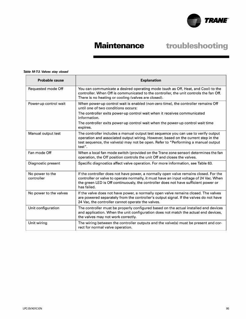
LPC-SVX01C-EN 95
Maintenance troubleshooting
Table M-T-3. Valves stay closed

96 LPC-SVX01C-EN
Maintenance troubleshooting
Table M-T-4. Outdoor air damper stays open
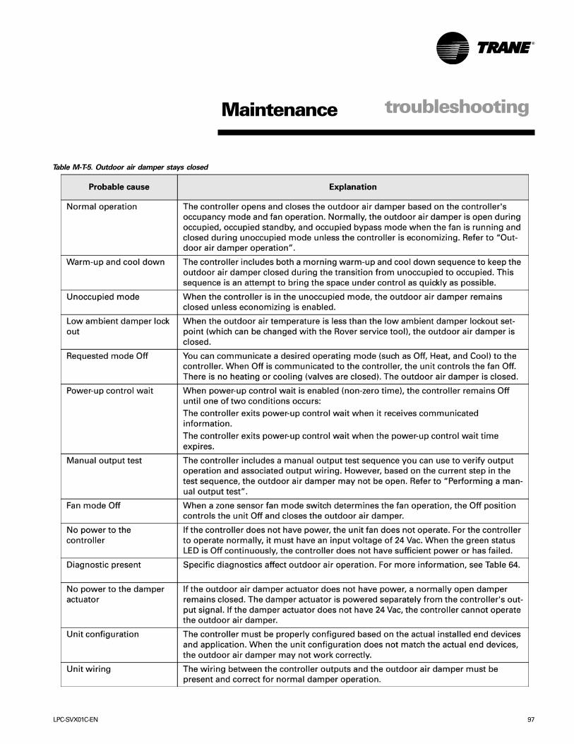
LPC-SVX01C-EN 97
Maintenance troubleshooting
Table M-T-5. Outdoor air damper stays closed

98 LPC-SVX01C-EN
Maintenance troubleshooting
Table M-T-6. DX cooling binary outputs do not energize

LPC-SVX01C-EN 99
Maintenance troubleshooting
Table M-T-7. Electric heat binary outputs do not energize

100 LPC-SVX01C-EN
Maintenancemaintenanceprocedures
Figure M-MP-1. Proper sheave clearance
and alignment.
Maintenance Procedures
Perform the following maintenanceprocedures to ensure proper unitoperation.
WARNINGLive Electrical Components!During installation, testing, servicing,and troubleshooting this equipment, itmay be necessary to work with liveelectrical components. Have aqualified licensed electrician or otherindividual who is properly trained inhandling live electrical componentsperform these tasks. Failure to followall electrical components could resultin death or serious injury.
WARNINGHazardous Voltage w/Capacitors!Disconnect all electric power,including remote disconnects anddischarge all motor start/runcapacitors before servicing. Followproper lockout/tagout procedures toensure the power cannot beinadvertently energized. For variablefrequency drives or other energystoring components provided by Traneor others, refer to the appropriatemanufacturer’s literature forallowable waiting periods fordischarge of capacitors. Verify with anappropriate voltmeter that allcapacitors have discharged. Failure todisconnect power and dischargecapacitors before servicing couldresult in death or serious injury.
Air FiltersReference unit air filter sizes in Table I-GI-1. Always install filters with directionalarrows pointing toward the fan.
Fan MotorsInspect fan motors periodically forexcessive vibration or temperature.Operating conditions will vary thefrequency of inspection and lubrication.Motor lubrication instructions are on themotor tag or nameplate. If for somereason these instructions are notavailable, contact the motormanufacturer. Some motormanufacturers may not provide oil tubeson motors with permanently sealedbearings.
Lubricating the MotorBefore lubricating the motor:1. Turn the motor off and disconnect
power to the unit to ensure the motordoesn’t accidentally start.
2. Use a No. 10 SAE, non-detergentautomotive type oil. Do not over-oil.
Fan BearingsFan bearings are permanently lubricatedand do not require additional lubrication.
Sheave AlignmentTo prevent interference of the fan framewith the belt, make sure that the beltedge closes to the motor has the properclearance from the fan frame as shown inFigure M-MP-1.
Align the fan and motor sheaves by usinga straight-edge or taut string, as shown inFigure M-MP-1. The straight-edge must belong enough to span the distancebetween the sheave outside edges.When the sheaves are aligned, thestraigt-edge will touch both sheaves atpoints A through D, as shown in Figure M-MP-1. For uneven width sheaves, place astring in the center groove of bothsheaves and pull tight. Adjust sheavesand tighten the sheave set screws to thecorrect torques recommended in TableM-MP-1.
Fan Assembly Set ScrewsCheck and adjust fan wheel, bearing, andsheave set screws whenever acomponent is removed or an adjustmentis made. Refer to Table M-MP-1 forrecommendations.
Fan Belt TensionProper belt tension is necessary toendure maximum bearing and drivecomponent life and is based on fan brakehorsepower requirements. Replace beltwhen frayed or worn.
Fan belt tension should only be tightenough so the belt does not slip andmaintains adequate airflow.
Note: Check fan belt tension at least twiceduring the first days of new belt operationsince there is a rapid decrease in tensionuntil belts are run-in.
Be careful not to over-tension fan belt.Excessive tension will reduce fan andmotor bearing life, accelerate belt wear,and possibly cause shaft failure. Cleanthe sheaves and belt with a dry cloth.Keep oil and grease away from the beltbecause they may cause beltdeterioration and slippage. Trane does notrecommend belt dressing.
CAUTION
Belt Tension!
Do not over-tension belts. Excessivebelt tension will reduce fan and motorbearing life, accelerate belt wear andpossibly cause shaft failure.

LPC-SVX01C-EN 101
Maintenancemaintenanceprocedures
Steam and Hydronic Coil CleaningProcedure1. Disconnect all electrical power to the
unit.2. Don the appropriate personal
protective equipment (PPE).3. Gain access to both sides of the coil.4. Use a soft brush to remove loose
debris from both sides of the coil.5. Use a steam cleaning machine, starting
from the top of the coil and workingdownward. Clean the leaving air side ofthe coil first, then the entering air side.Use a block-off to prevent steam fromblowing through the coil and into a drysection of the unit.
6. Repeat step 5 as necessary. Confirmthat the drain line is open followingcompletion of the cleaning process.
7. Allow the unit to dry thoroughly beforeputting the system back into service.
8. Straighten any coil fins that may bedamaged with a fin rake.
9. Replace all panels and parts andrestore electrical power to the unit.
10. Ensure that contaminated materialdoes not contact other areas of the unitor building. Properly dispose of allcontaminated materials and cleaningsolutions.
Winterizing the CoilMake provisions to drain coils that are notin use, especially when subjected tofreezing temperatures.
To drain the coil, first blow out the coilwith compressed air. Next, fill and drainthe tubes with full-strength ethyleneglycol several times. Then drain the coil ascompletely as possible.
CAUTIONCoil Freeze-up Damage!Failure to properly drain and ventcoils when not in use during freezingtemperatures may result in coilfreeze-up damage.
Coil Maintenance
Keep coils clean to maintain maximumperformance. For operation at its highestefficiency, clean the coil often duringperiods of high demand or when dirtyconditions prevail. Clean the coil aminimum of once a year to prevent dirtbuildup in the coil fins, where it may notbe visible.
Remove large debris from the coils andstraighten fins before cleaning. Removefilters before cleaning.
Clean the coil fins using steam withdetergent, hot water spray and deter-gent, or a commercially availablechemical coil cleaner. Be sure to rinsecoils thoroughly after cleaning.
WARNINGHazardous Chemicals!Coil cleaning agents can be eitheracidic or highly alkaline. Handlechemical carefully. Proper handlingshould include goggles or face shield,chemical resistant gloves, boots,apron or suit as required. For personalsafety refer to the cleaning agentmanufacturer’s Materials Safety DataSheet and follow all recommendedsafe handling practices. Failure tofollow all safety instructions couldresult in death or serious injury.
Inspecting and Cleaning CoilsCoils become externally fouled as a resultof normal operation. Dirt on the coilsurface reduces it’s ability to transfer heatthat can result in comfort problems,increased airflow resistance and thusincreased operating energy costs. If thecoil surface dirt becomes wet, whichcommonly occurs with cooling coils,microbial growth (mold) may result,causing unpleasant odors and serioushealth-related indoor air qualityproblems.
Inspect coils at least every six months ormore frequently as dictated by operatingexperience. Cleaning frequently isdependent upon system operating hours,filter maintenance, and efficiency and dirtload. Follow the suggested methods inthe following paragraphs.
Refrigerant Coil Cleaning Procedure1. Disconnect all electrical power to the
unit.2. Wearing the appropriate personal
protective equipment, use a soft brushto remove loose debris from both sidesof the coil.
3. Install a block-off to prevent spray fromgoing through the coil and into a drysection of the unit and/or systemductwork.
WARNINGHazardous Pressures!Coils contain refrigerant underpressure. When cleaning coils,maintain coil cleaning solutiontemperature under 150°F to avoidexcessive pressure in the coil. Failureto follow these safety precautionscould result in coil bursting, whichcould result in death or serious injury.
4. Mix a high-quality coil cleaningdetergent with water according to themanufacturer’s instructions.
Note: If the detergent is strongly alkalineafter mixing (pH of 8.5 or higher), it mustcontain an inhibitor. Follow the cleaningsolution manufactuer’s instructionsregarding the use of the product.
5. Place the mixed solution in a gardenpump-up sprayer or high-pressuresprayer. If using a high-pressuresprayer, follow these guidelines:
• maintain minimum nozzle spray angle of15 degrees
• spray perpendicular to the coil face• keep the nozzle at least six inches from
the coil• do not exceed 600 psi6. Spray the leaving air side of the coil
first, then the entering air side.7. Thoroughly rinse both sides of the coil
and drain pan with cool, clean water.8. Repeat steps 6 and 7 as necessary.9. Straighten any coil fins damaged
during the cleaning process.10. Confirm the drain line is open
following the cleaning process.11. Allow the unit to dry thoroughly before
putting it back into service.12. Replace al panels and parts and
restore electrical power to the unit.13. Do not allow contaminated material
to contact other areas of the unit orbuilding. Properly dispose of allcontaminated materials and cleaningsolution.
102 LPC-SVX01C-EN
Periodic MaintenanceChecklists
Monthly ChecklistThe following check list provides therecommended maintenance schedule tokeep the unit running efficiently.
WARNINGLive Electrical Components!During installation, testing, servicing,and troubleshooting this equipment, itmay be necessary to work with liveelectrical components. Have aqualified licensed electrician or otherindividual who is properly trained inhandling live electrical componentsperform these tasks. Failure to followall electrical components could resultin death or serious injury.
WARNINGHazardous Voltage w/Capacitors!Disconnect all electric power,including remote disconnects anddischarge all motor start/runcapacitors before servicing. Followproper lockout/tagout procedures toensure the power cannot beinadvertently energized. For variablefrequency drives or other energystoring components provided by Traneor others, refer to the appropriatemanufacturer’s literature forallowable waiting periods fordischarge of capacitors. Verify with anappropriate voltmeter that allcapacitors have discharged. Failure todisconnect power and dischargecapacitors before servicing couldresult in death or serious injury.
1. Inspect unit air filters. Clean or replaceif airflow is blocked or if filters are dirty.
2. Check the condition and tension of fanbelts. Adjust tension if belts are floppyor squeal continually. Replace worn orfraying belts in matched sets.
maintenanceprocedures
Note: Check and adjust belt tension atleast twice daily the first days of new beltoperation. Belt tension will rapidlydecrease until the belts are run in.
3. Re-lubricate motor bearings, if motor isfitted with oil tubes and operatingconditions include moist or dirty air,continuous duty and/or hightemperatures.
Semi-Annual Maintenance1. Verify the fan motor is properly
lubricated. Follow lubricationrecommendations on the motor tag ornameplate. Contact the motormanufacturer for more information.
2. Check bearing locking collar andsheave set screws for proper tightness.
3. With power disconnected, manuallyrotate the fan wheel to check forobstructions in the housing orinterference with fan blades. Removeany obstructions and debris.
4. Check the fan assembly sheavealignment. Tighten set screws to theirproper torques.
5 Check fan belt tension. Adjust the belt ifit is slipping. Replace if belt is worn orfrayed.
6. Inspect the coils for dirt build-up. Cleanfins if airflow is clogged.
Maintenance
Annual MaintenanceCheck and tighten all set screws, bolts,locking collars and sheaves.1. Inspect, clean, and tighten all electrical
connections and wiring.2. Visually inspect the entire unit casing
for chips or corrosion. Remove rust orcorrosion and repaint surfaces.
3. Clean fan wheels and fan shaft.Remove any rust from the fan shaftwith an emergy cloth and recoat withL.P.S. 3 or equivalent.
4. Inspect the drainpan for sludge or otherforeign material. Clear the drainopenings and drain line to ensureadequate flow.
5. Rotate the fan wheel and check forobstructions in the fan housing. Thewheel should not rub on the fanhousing or cutoff. Adjust to center ifnecessary and tighten the wheel setscrews per torque recommendations inTable M-A-1.
6. Examine flex connector for cracks orleaks.
7. Repair or replace any damaged ductmaterial.
Note: Reference the Appendix forrecommended torques for tighteningsheaves, bearing thrust collar, belt,bearing mounting bolts, sheave setscrew, sheave bushing cap and damperlinkage components.

LPC-SVX01C-EN 103
Instructions for Changing Out SpringIsolators on LPC
Unit Sizes 3 through 10:Units ranging in size from 3 to 10 use a 1”defelection isolator assembly like the oneshown in the figure below. Lateralmovement is limited by the snubber bolt.The spring is supported at the bottom bythe isolator bracket, but the two are notmechanically attached to one another.To change out the spring in this type ofassembly perform the following steps:1. Disconnect power to the unit.2. Loosen the lock nuts on the snubber
bolts for all four corners. Remove thelock nut the spring that needs to beremoved.
3. Elevate the isolation base so that theweight of the fan and mtor isremoved from the spring. The pictureshown below is of an unloaded springwith the isolation base held up byblocks.
4. Loosen the flange nut at the base ofthe snubber bolt from rotating whileloosening the flange nut.
5. Remove the nuts that were cinchedtogether in the step above. As theflange nit is being loosened, thesnubber bolt should drop down insidethe isolator bracket.
Maintenancemaintenanceprocedures
Units ranging in size from 12 to 30 use a2” deflection isolator assembly like theone shown in the picture below. Lateralmovement is limited by snubber brackets(not shown). The spring is supported atthe bottom by the isolator bracket, but thetwo are not mechanically attached tooneanother. Another identical isolator bracketis inverted and is located above thespring. An adjustment bolt runs thro9ughtheh top bracket and pushed against athesping cap resting on the top of the spring.To change out the spring in this tupe ofassembly perform the following steps:1. Disconnect power from the unit2. Loosen and remove the adjustment
bolt3. Remove the sping cap and spring4. In some cases there is not enough
clearance between the top isolatorbracket andthe cabinet to allow thespring mounting screws. Be sure theisolation base is secured or elevatedwith blocks before removing the topbracket
5. Replace old spring with a new oneand also replace the spring cap
6. Reattch top isolator bracket ifremoved in step 3
7. Return adjustment bolt to its originalposition so that the isolation baseassembly is level
Unit Sizes 12 through 30:
Figure M-MP-3. Two-inch Deflection Isolator Assembly
6. Push the snubber bolt down thoughthe isolation base into the isolationbracket as far as it will go. This shouldallow some space between the endof the snubber bolt and the isolationbase.
7. Remove old spring and replace withnew one.
8. Tighten flange nut until snubber boltis back to its original position. The nutsthat were cinched together in step 3may be needed again to prevent thebolt from rotating while the flange nutis being tightened.
9. Replace washers and lock nut.10. Remove blacoks holding up the
isolation base and tighten all lock nutsto their original postion so thatisolation assembly is level.
Figure M-MP-2. One-inch Deflection Isolator Assembly
I s o l a t i o nB a s e
S p r i n g
S h i p p i n gT i e - d o w n B o t t o m
I s o l a t o rB r a c k e t
B r a c k e tM o u n t i n gS c r e w s
T o p I s o l a t o rB r a c k e t
A d j u s t m e n t B o l t

104 LPC-SVX01C-EN
Maintenance appendix
Figure M-A-1. Flowchart
Entering Water TemperatureSampling Function

LPC-SVX01C-EN 105
Maintenance appendix
Input Sensor Tables Table M-A-2. Trane zone sensor hard-wired setpoint thumbwheel
Table M-A-3. Hard-wired 10 kΩΩΩΩΩ thermistor values

106 LPC-SVX01C-EN
Maintenance appendix
Table M-A-4. Hard-wired 1kΩΩΩΩΩ mixed-air sensor
Table M-A-5. Hard-wired relative humidity sensor values

LPC-SVX01C-EN 107
Maintenance appendix
Table M-A-6. Hard-wired CO2 sensor values

108 LPC-SVX01C-EN
Table M-A-8 Minimum Torques for Bearing
Mounting Bolts, Belt Tightening
Bolts and Motor Mounting Bolts
Size Inch Lbs. Foot Lbs. N-m1/40-20 72 6 8.135/16-18 168 14 18.983/8-16 288 24 32.547/16-14 504 42 56.941/2-13 828 69 93.55
Note: all torque values are +/- 5%.
Table M-A-9. Sheave Set Screw
Torque Recommendations
Screw Diameter (in.) 0.313 0.313Screw Diameter (cm) 0.795 0.795Screw Length (in.) </= 0.250 >/= 0.313Screw Length (cm) </= 0.635 >/= 0.795Torque (Inch Lbs) 90 165Torque (Foot Lbs) 7.5 13.75Torque (N-m) 10.17 18.64Note: all torque values are +/- 5%.
Table M-A-10. Sheave Bushing Cap
Screw Torque
Recommendations
Screw Diameter (in.) 0.25 0.313 0.375Screw Diameter (cm) 0.635 0.795 0.953Torque (Inch Lbs) 95 192 348Torque (Foot Lbs) 7.92 16 29Torque (N-m) 10.73 21.69 39.32Note: all torque values are +/- 5%.
Table M-A-11. Minimum Recommended Torques for Damper Linkage Components
Item TorqueInch Lbs. Foot Lbs. N-m
Square head set screw - 1/4 - 20 90 7.50 10.17Hex head set screw - 1/4 - 20 65 5.42 7.34Hex head set screw - 5/16 - 24 144 12.00 16.27Ball joint set screw - 1/4 - 28 thread 40 3.33 4.52Ball joint set screw - 5/16 - 24 144 12.00 16.27Note: all torque values are +/- 5%.
Table M-A-7. Recommended Torques for Tightening Bearings Thrust Collar
unit SKF Browning NTNsize in-lbs ft-lbs N-m in-lbs ft-lbs N-m in-lbs ft-lbs N-m
3 66 - 80 5.5 - 6.7 7.5 - 9.0 66 - 85 5.5 - 7.1 7.5 - 9.6 N/A N/A N/A
6 66 - 80 5.5 - 6.7 7.5 - 9.0 66 - 85 5.5 - 7.1 7.5 - 9.6 N/A N/A N/A
8 66 - 80 5.5 - 6.7 7.5 - 9.0 66 - 85 5.5 - 7.1 7.5 - 9.6 N/A N/A N/A
10 66 - 80 5.5 - 6.7 7.5 - 9.0 66 - 85 5.5 - 7.1 7.5 - 9.6 N/A N/A N/A
12 87 7.25 9.83 N/A N/A N/A 43 3.58 4.86
14 87 7.25 9.83 N/A N/A N/A 43 3.58 4.86
17 165 13.75 18.64 N/A N/A N/A 52 4.33 5.88
21 165 13.75 18.64 N/A N/A N/A 69 5.75 7.80
Maintenance appendix


a business of American Standard Inc.www.trane.com
For more information contactyour local office or e-mail us [email protected]
Literature Order Number
File Number
Supersedes
Stocking Location
Trane has a policy of continuous product improvement and reserves the right to change design and specificationswithout notice. Only qualified technicians should install and service equipment.
LPC-SVX01C-EN
PL-AH-LPC-SVX01C-EN 07/06
LPC-SVX01A-EN 06/00
LaCrosse - Inland
US