installation, operation, & maintenance manualcamcorpinc.com/useful_info/dust collector-baghouse-...
TRANSCRIPT

Installation, Operation,& Maintenance Manual
Unique Design & Engineering Approaches for Industrial Applications
�������
�����
��������������������������������
�� ��������������� ��������������� ��������������� �������������
��������������������������������������������������������
CAMCORP, INC. Phone: 913-831-0740 Fax: 913-831-9271
www.camcorpinc.com
TABLE OF CONTENTS Section 1 - SAFETY
Safety Recommendations ............................................................................ 1-1 Section 2 - RECEIVING
Receiving & Inspection of the Unit............................................................. 2-1 Storage Recommendations .......................................................................... 2-2 Section 3 - INSTALLATION
Setting Up Your Unit................................................................................... 3-1 Bag & Cage Installation .............................................................................. 3-5 Electrical Wiring Diagram......................................................................... 3-11 Magnehelic Gauge Connections................................................................ 3-12 Explosion Vent Installation ....................................................................... 3-13 Section 4 - OPERATION
Operating Principle...................................................................................... 4-1 Start-Up Check List ..................................................................................... 4-2 Start-Up Dust Control Systems ................................................................... 4-5 Shutdown Procedures .................................................................................. 4-6 Section 5 – COMPONENT INFORMATION
Main Component Listing............................................................................. 5-1
Magnehelic Gauge ....................................................................................... 5-3 Timer............................................................................................................ 5-7 National Controls Corp – 120 VAC Standard Timer ............................ 5-7 National Controls Corp – 12-24 VDC (Optional) ................................. 5-9 Dwyer Smart Timer (Optional) ........................................................... 5-11 Diaphragm Valves ..................................................................................... 5-19 Goyen #RCA20DD – ¾” Valve ........................................................... 5-19 Goyen #RCA25DD – 1” Valve ............................................................ 5-20 Goyen #RCA45DD – 1 ½” Valve ........................................................ 5-21

CAMCORP, INC. Phone: 913-831-0740 Fax: 913-831-9271
www.camcorpinc.com
Section 6 - TROUBLESHOOTING
Dust Collector .............................................................................................. 6-1 Timer............................................................................................................ 6-5 Compressed Air System .............................................................................. 6-6 Section 7 - MAINTENANCE
Routine Maintenance ................................................................................... 7-1 Section 8 – APPENDIX
Dust Collector Terms & Definitions ........................................................... 8-1
CAMCORP, INC. Phone: 913-831-0740 Fax: 913-831-9271
www.camcorpinc.com
Section 1 – Safety Recommendations
Because this unit may be under pressure or vacuum do not attempt to open any device, doors or panels while fans or blowers are running. The unit has air hoses and valves with a maximum recommended operating pressure of 100 psig. To eliminate the danger of bursting care must be taken to insure maximum desired pressure is not exceeded. Before servicing any portion of the compressed air system the air supply must be shut off and any pressure relieved. If your unit is equipped with a discharge auger or an airlock assure that chain guards are installed before start-up and servicing is attempted only after electrical power is locked out. While servicing the filter it is very important that there are no open flames, welding or grinding sparks. Dust laden air could be highly explosive and extreme care must be taken. Most filter bags will burn if exposed to sparks, welding or open flames. Before entering any dust collector:
• Run cleaning mechanism 20 minutes with the fan off to clean filter bags. • Completely discharge dust solids from hopper, if applicable. • Shut off compressed air supply and relieve pressure in the compressed air
manifold. • Lock out all electrical power on all equipment especially rotating
equipment. • On toxic operation, purge collector housing and install a blank in the inlet
duct. • Install catwalks and safety cables as required. • Secure access doors in an open position or remove doors. • Use the buddy system. • Wear a respirator or appropriate breathing equipment. • Use common sense.
Follow all current OSHA regulations relative to Lockout / Tag-Out and Confined Space Entry and any other applicable regulations when servicing your equipment. On the following page are examples of safety stickers you will find on Camcorp equipment. These will help identify potential hazards on the equipment.
1-1

Examples of Safety Stickers
CAMCORP, INC. Phone: 913-831-0740 Fax: 913-831-9271
www.camcorpinc.com
------DANGER------
The DANGER & CAUTION stickers indicate serious potential hazards which may result in serious injury or possible death. Extreme care should be observed when working in these areas.
-----CAUTION------
1-2
-------OTHER-------
These stickers provide instruction or helpful information. Serial Number Plate
Important information contained on these is needed by Camcorp when calling for parts or service.

CAMCORP, INC. Phone: 913-831-0740 Fax: 913-831-9271
www.camcorpinc.com
Section 2 - Receiving Receiving the Equipment
Prior to accepting the shipment(s) care must be taken to inspect all equipment received both for proper count and for damage. Any and all irregularities must be noted on the carrier’s copy of the shipping receipt to assist in settling any claims for damage or shortages. All equipment is shipped FOB point of origin whether on a prepaid or collect freight basis.
ANY CLAIM FOR DAMAGE IN TRANSIT OR SHORTAGES MUST BE BROUGHT AGAINST THE CARRIER BY THE PURCHASER.
Once your claim has been filed with the carrier, contact CAMCORP to notify us of the problem(s). We will then advise the appropriate repair procedure or recommend it be returned to our factory, depending on the extent of the damage.
Inspection of the Equipment
Housing, Compressed Air Header and Timer Assembly: Particular attention should be paid to the sheet metal housing of your collector. The unit should be inspected for dents, cracks or rips. A dented housing may seriously affect the structural integrity of the unit. The compressed air header and timer assembly are very delicate pieces of the unit and must be checked carefully for any signs of impact, warpage or loose fittings. If any of these signs are present note them on the shipping receipt and notify CAMCORP immediately. The entire unit should be checked against the certified drawings for correctness. CAMCORP should be notified immediately if there are any discrepancies. No corrections may be made without the expressed written consent of CAMCORP. Components: A count should be made of all pieces received and this should be verified against the carrier’s manifest. Boxes should be inspected for rough handling, which may have resulted in hidden damage.
2-1
CAMCORP, INC. Phone: 913-831-0740 Fax: 913-831-9271
www.camcorpinc.com
Storage Recommendations Baghouse, Bin Vent, Filter Receiver, Dirty Air Hopper and Housing
• Housing can be stored outside. • Equipment must be blocked up to keep the flanges out of the dirt. • Most units are supplied with a plain unfinished interior. If storage of more
than two weeks is anticipated the interior should be prime coated before storage.
• Covering the unit with a tarp is recommended to help keep the interior from rusting or corroding as well as keeping the outer finish in new condition, however a tarp is not absolutely necessary.
Baghouse, Bin Vent, Filter Receiver, and Clean Air Plenum
• Unit can be stored outside. • Compressed air header, diaphragm and solenoid valves must be tarped
for weather protection. • Position unit so water will not get in or remain inside the tube sheet area. • Unit must be blocked up to keep the flanges, bag cups, venturis and air
header out of water and dirt. • Ports on diaphragm and solenoid valves must be plugged and taped to
keep insects, dirt and moisture out. • For extended storage (more than 4 weeks), it is recommended to remove
the timer panel and solenoid valve assembly (if mounted). These components should be stored inside a cool dry area along with the copper or black nylon tubing. The solenoids should have all ports capped and taped to protect from insects, dirt and moisture.
• The unit should be tarped but is not absolutely necessary. Filter Bags & Cages
• Filter bags must be stored inside a cool dry area protected from moisture, rodents and insects.
• For extended storage the boxes for the bags should be wrapped with plastic wrap or stretch wrap to protect from moisture.
• If the bags get wet for any reason, immediately lay them out with plenty of ventilation to dry in order to prevent mold and mildew.
• It is recommended to store the cages inside a dry area if at all possible. • If an inside location is not available the cages can be stored outside as
long as they are covered by a tarp. • Cages are generally stored horizontally on pallets to keep them off the
ground.
2-2

CAMCORP, INC. Phone: 913-831-0740 Fax: 913-831-9271
www.camcorpinc.com
Storage Recommendations (continued)
• If cages can be stored horizontally do not stack over three boxes high. • If the job site is in an area that may receive a significant snow load the
cages must be stored vertically in order to prevent being crushed by the weight of the snow. Do not stack more than one box high.
Accessory Parts
• This includes all gauges, bag clamps, nylon or copper tubing, valves, gaskets and other parts not specifically called out.
• These items should be stored inside a cool dry place protected from moisture, insects, and rodents.
Fan and Fan Accessories
• Fans can be stored outside on a pallet or skid to keep them out of water and dirt.
• Fan silencers, outlet dampers, and inlet boxes should also be tarped and stored on a pallet or skid.
• Reference fan IOM manual for long-term storage. Ducting
• Ducting can be stored outside on a pallet or skid to keep it off the ground. It should be positioned so that water does not sit on or in the ducting.
• If ducting is unpainted carbon steel it should be at least primed coated before storage.
• If ducting is already finish coated, it should be tarped to protect the finish, but this is not absolutely necessary.
Knife Gate
• All limit switches, solenoids, and air cylinder ports must be capped and taped to prevent any moisture or dirt from entering.
• Equipment can sit outside provided it is covered with a tarp and is on a pallet or skid to keep it out of water and dirt.
• Reference knife gate IOM manual for long-term storage.
2-3

CAMCORP, INC. Phone: 913-831-0740 Fax: 913-831-9271
www.camcorpinc.com
Storage Recommendations (continued) Isolation Dampers
• All limit switches, solenoids, and air cylinder ports must be capped and taped to prevent any moisture or dirt from entering.
• Equipment can sit outside provided it is covered with a tarp and is on a pallet or skid to keep it out of water and dirt.
Rotary Valve
• Rotor and interior of valve should be well oiled with vegetable oil to prevent rust and to maintain compatibility with product.
• Unit can be stored outside provided it is covered with a tarp and is on a pallet or skid to keep it out of water and dirt.
• Reference rotary valve IOM manual for long-term storage. Butterfly (Wafer Valve)
• All limit switches, solenoids, and air cylinder ports must be capped and taped to prevent any moisture or dirt from entering.
• Unit can be stored outside provided it is covered with a tarp and is on a pallet or skid to keep it out of water, dirt and sunlight.
• Reference butterfly valve IOM manual for long-term storage. Level Indicators
• Store these items inside a protected cool dry area. AC Inverters
• Store these items and all other electrical controls inside a protected cool dry area.
2-4
CAMCORP, INC. Phone: 913-831-0740 Fax: 913-831-9271
www.camcorpinc.com
Section 3 - Installation
Setting Up Your Unit
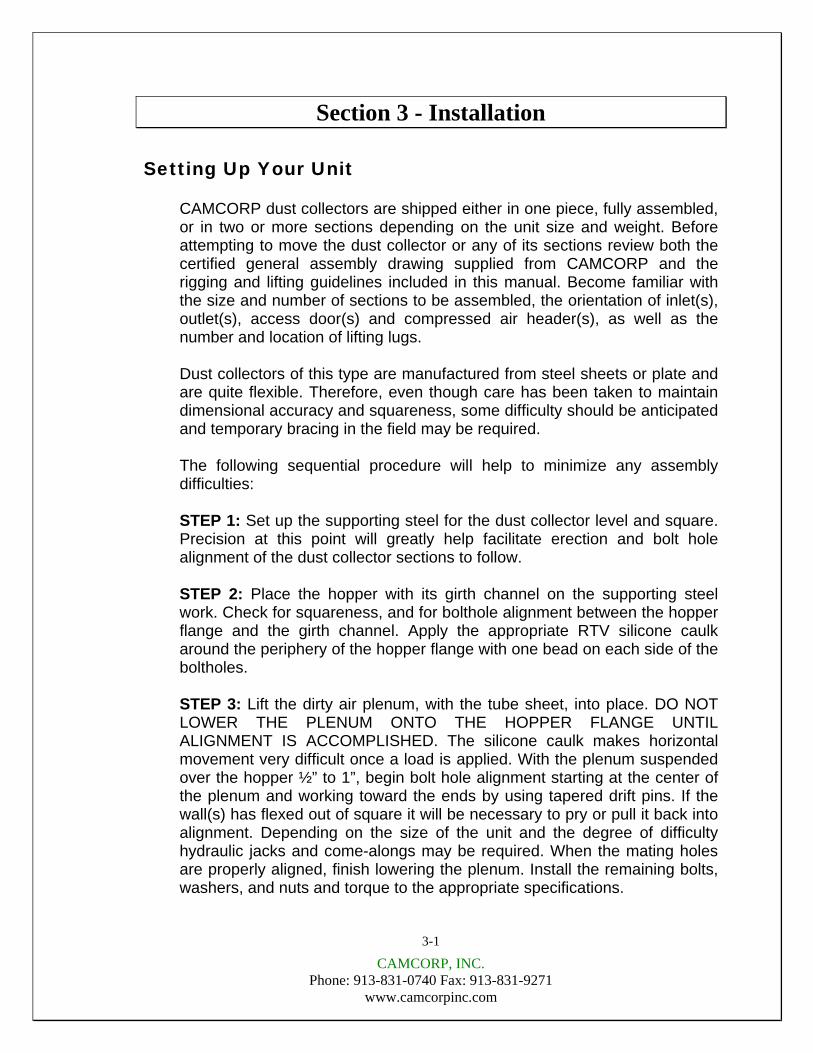
CAMCORP dust collectors are shipped either in one piece, fully assembled, or in two or more sections depending on the unit size and weight. Before attempting to move the dust collector or any of its sections review both the certified general assembly drawing supplied from CAMCORP and the rigging and lifting guidelines included in this manual. Become familiar with the size and number of sections to be assembled, the orientation of inlet(s), outlet(s), access door(s) and compressed air header(s), as well as the number and location of lifting lugs. Dust collectors of this type are manufactured from steel sheets or plate and are quite flexible. Therefore, even though care has been taken to maintain dimensional accuracy and squareness, some difficulty should be anticipated and temporary bracing in the field may be required. The following sequential procedure will help to minimize any assembly difficulties: STEP 1: Set up the supporting steel for the dust collector level and square. Precision at this point will greatly help facilitate erection and bolt hole alignment of the dust collector sections to follow. STEP 2: Place the hopper with its girth channel on the supporting steel work. Check for squareness, and for bolthole alignment between the hopper flange and the girth channel. Apply the appropriate RTV silicone caulk around the periphery of the hopper flange with one bead on each side of the boltholes. STEP 3: Lift the dirty air plenum, with the tube sheet, into place. DO NOT LOWER THE PLENUM ONTO THE HOPPER FLANGE UNTIL ALIGNMENT IS ACCOMPLISHED. The silicone caulk makes horizontal movement very difficult once a load is applied. With the plenum suspended over the hopper ½” to 1”, begin bolt hole alignment starting at the center of the plenum and working toward the ends by using tapered drift pins. If the wall(s) has flexed out of square it will be necessary to pry or pull it back into alignment. Depending on the size of the unit and the degree of difficulty hydraulic jacks and come-alongs may be required. When the mating holes are properly aligned, finish lowering the plenum. Install the remaining bolts, washers, and nuts and torque to the appropriate specifications.
3-1
CAMCORP, INC. Phone: 913-831-0740 Fax: 913-831-9271
www.camcorpinc.com
Setting Up Your Unit (continued)
Step 4: Check the top of the dirty air plenum for squareness and bolthole alignment between the dirty air plenum and the tube sheet. Make sure that the silicone caulk has been applied between the top flange of the dirty air plenum and the underside of the tube sheet flange. Next, apply the caulk around the periphery of the topside of the tube sheet flange one bead to each side of the boltholes.
STEP 5: Lift the clean air plenum into place and assemble in the same fashion as in STEP 3. Again, do not lower the clean air plenum completely until preliminary alignment is accomplished. Start drift pin alignment at the center of the plenum on the compressed air header side since the header makes access to the flange more limited. When alignment is complete install the remaining bolts, washers, and nuts and torque to the appropriate specifications.
All CAMCORP dust collectors are provided with lifting lugs for ease in handling of the units during field erection and installation. The number and location of these lifting lugs will vary depending on the model, size, and weight of the dust collector. Before attempting to rig and lift your dust collector review the certified general assembly drawing supplied from CAMCORP to verify the number and location of lifting lugs as well as visually checking this information on the actual unit. Large units are frequently shipped in several sections so check the lifting lugs provided on each section. If these cannot be used or there is some question about lifting lug location consult the engineering staff at CAMCORP for proper location since proper care must be taken to prevent damage to housing or its components.
Rigging and Lifting Guidelines
Do not lift the dust collector by any attachments other than the lifting lugs provided.
Use all of the lifting lugs provided on the dust collector or a section of the dust collector when making a lift.
If the lifting lugs are located below the roofline of the dust collector or below the top of the section of the dust collector a vertical pull must be made to avoid crushing the top of the unit. Use spreader beams to accomplish this vertical pull.
3-2

CAMCORP, INC. Phone: 913-831-0740 Fax: 913-831-9271
www.camcorpinc.com
Setting Up Your Unit (continued)
Attach tag lines at several locations to help in controlling the unit when lifted and to prevent spinning or swinging. The dust collector should be lifted and lowered at a slow, uniform rate and not allowed to bounce or joggle since this can cause excessive impact stresses at the lift points.
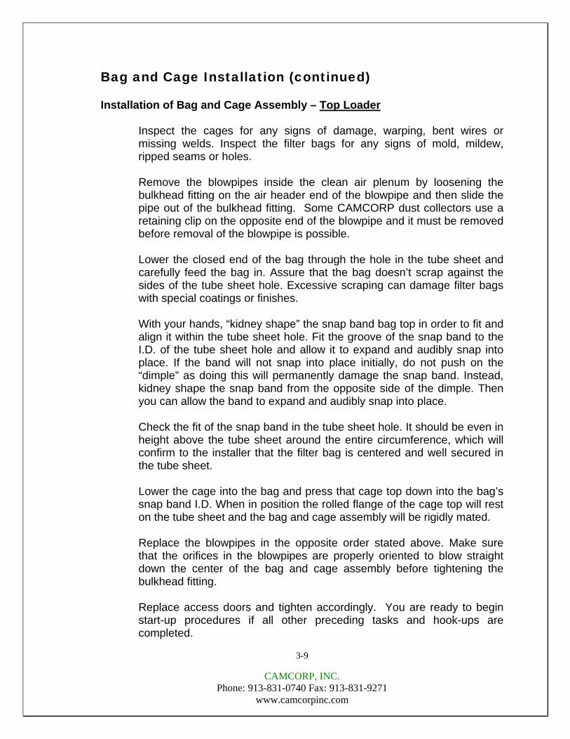
Compressed Air Manifold: Typically, CAMCORP ships the compressed air manifold installed complete with diaphragm valves and solenoid enclosure(s), except when units are over legal shipping width with them in place. Doors and Flanges: Hold-downs on doors should only be hand tightened. Excessive pressure can distort the door panel itself resulting in leakage. All bolts on flanges should be tight. All ports in the dust collector not being used must be plugged prior to start-up. Electrical: A 120 volt 60 Hertz circuit is required to operate the dust collector’s pulse-jet cleaning system (unless a different voltage for components was requested). This timer must be wired according to the wiring diagrams and be provided with a circuit that is free from transient currents. The timer has a feature called “Demand Pulse” that allows the output terminals to be energized and de-energized by the high and low set points of a differential pressure switch such as a Dwyer Photohelic Series 3000. The “Demand Pulse” terminals are marked “Pressure Switch”. Do not over fuse. The NCC pulse timer boards have adjustable pulse duration and interval (time between valves firing) settings. Before applying power to the timer always check these settings according to the table below. Since there are many variances in operations and conditions these are presented only as initial start-up guidelines. If you experience problems in cleaning of the filter bags, please contact CAMCORP.
TIMER BOARD ADJUSTMENTS (Recommended at start-up)
VALVE SIZE PULSE DURATION INTERVAL ¾” .10 to .12 seconds 20 to 25 seconds 1” .10 to .12 seconds 20 to 25 seconds 1-½” .06 to .08 seconds 20 to 25 seconds
3-3
CAMCORP, INC. Phone: 913-831-0740 Fax: 913-831-9271
www.camcorpinc.com
Setting Up Your Unit (continued)
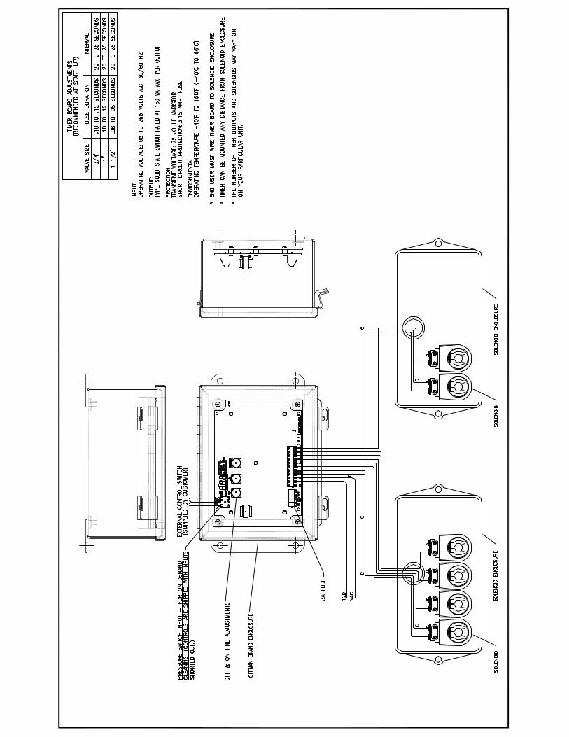
The firing sequence of the diaphragm valves on the dust collector should be set so that no two adjacent rows of bags fire in succession to insure maximum cleaning and life of the filter media. This can only be achieved when wiring the pulse timer board to the solenoid valves. If you are experiencing a high-pressure drop across the filter bags in your dust collector the pulse interval should be reduced. Apply electrical power to the timer and make sure that it is cycling completely through all rows of the unit. In some cases the timer panel may have more “positions” than required in which case the position selector cable needs to be attached to the proper numerical value corresponding to the number of diaphragm valves on the unit. If your dust collector was shipped via common carrier rather than a contract hauler there is a possibility that the solenoid enclosure was not shipped installed on the unit. If this is the case, there is a mounting plate welded on the housing or the air header with the bolt pattern of the enclosure already drilled. Bolt the enclosure and install the nylon (or copper) tubing with the fittings provided making sure that the solenoids are connected to their corresponding diaphragm valve. Valves and Piping: After the unit has been installed the diaphragm valves should be checked to make sure that the port marked “IN” is assembled to the compressed air manifold. The “IN” connection of the solenoid valve is connected to the diaphragm valve by means of ¼” nylon or ¼” copper refrigeration tubing. Each nut on the compression fittings should be checked for tightness before the compressed air manifold is pressurized. In most cases a slip fit fitting has been used. The integrity of the nylon tubing inside each fitting should be checked by pulling gently on each tube. If the tube pulls out, simply push it back into the fitting until it will not go any further. The solenoids are shipped with a plastic plug in the discharge side of the valve. These plugs must be removed for proper operation. Gauges: The differential pressure gauge, mounting bracket, fittings and tubing are usually shipped loose in a box with the dust collector. When installing these make sure that the high-pressure port of the gauge is connected below the tube sheet and the low-pressure port is connected above the tube sheet on the dust collector. There are pipe couplings welded on the side of the dust collector for these connections. After the differential pressure gauge is permanently mounted the gauge needs to be zeroed prior to connecting the tubing to the gauge.
3-4
CAMCORP, INC. Phone: 913-831-0740 Fax: 913-831-9271
www.camcorpinc.com
Auxiliary Equipment: All auxiliary equipment must be installed according to its manufacturer’s specifications and interlocked with the entire system as needed. Direction of rotation of each item must be checked prior to start-up of the entire system.
3-5

CAMCORP, INC. Phone: 913-831-0740 Fax: 913-831-9271
www.camcorpinc.com
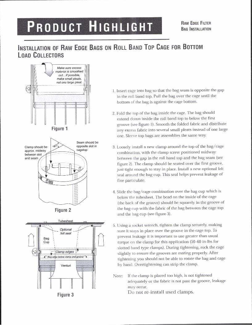
Bag and Cage Installation Installation of Bag and Cage Assembly – Bottom Loader
Inspect the filter bag cages for any signs of damage, warping, bent wires or missing welds. Inspect the filter bags for any signs of mold, mildew, ripped seams or holes.
Be sure the wire cage has a bottom pan. Slip the filter bag over the cage, centering the seam 1-½” or 2” on either side of the split at the top of the cage roll band. Seam must be straight (not corkscrewed). Make sure that the filter bag bottom is tight against the cage bottom pan.
Pull the bag up and over the full length of the cage and fold the entire extra length over and down inside the top of the cage. Smooth out any filter bag folds inside the top of the cage.
Slip the assembled filter bag and cage over the outside of the bag cup (mounted on the tube sheet) making sure to mate the male groove of the cage roll band top to the female groove of the bag cup.
If you try to move the assembly up and down you will be able to tell if the grooves are properly aligned.
Install the worm gear bag clamp on the assembly and tighten around the bag and cage at the point just above the groove on the cage. The clamp head should be located in the best position for ease in tightening.
Tighten the clamp until secure. You should not be able to rotate the bag-cage assembly by hand if it is tighten properly.
Close the access door and tighten accordingly. You are ready to begin start-up procedures if all other preceding tasks and connections are completed. It is recommended to double check the tightness of the bag and cage assembly approximately one month after the initial start-up.
3-6
CAMCORP, INC. Phone: 913-831-0740 Fax: 913-831-9271
www.camcorpinc.com
Bag and Cage Installation (continued) Installation of Bag and Cage Assembly – Top Loader
Inspect the cages for any signs of damage, warping, bent wires or missing welds. Inspect the filter bags for any signs of mold, mildew, ripped seams or holes.
Remove the blowpipes inside the clean air plenum by loosening the bulkhead fitting on the air header end of the blowpipe and then slide the pipe out of the bulkhead fitting. Some CAMCORP dust collectors use a retaining clip on the opposite end of the blowpipe and it must be removed before removal of the blowpipe is possible.
Lower the closed end of the bag through the hole in the tube sheet and carefully feed the bag in. Assure that the bag doesn’t scrap against the sides of the tube sheet hole. Excessive scraping can damage filter bags with special coatings or finishes.
With your hands, “kidney shape” the snap band bag top in order to fit and align it within the tube sheet hole. Fit the groove of the snap band to the I.D. of the tube sheet hole and allow it to expand and audibly snap into place. If the band will not snap into place initially, do not push on the “dimple” as doing this will permanently damage the snap band. Instead, kidney shape the snap band from the opposite side of the dimple. Then you can allow the band to expand and audibly snap into place.
Check the fit of the snap band in the tube sheet hole. It should be even in height above the tube sheet around the entire circumference, which will confirm to the installer that the filter bag is centered and well secured in the tube sheet.
Lower the cage into the bag and press that cage top down into the bag’s snap band I.D. When in position the rolled flange of the cage top will rest on the tube sheet and the bag and cage assembly will be rigidly mated.
Replace the blowpipes in the opposite order stated above. Make sure that the orifices in the blowpipes are properly oriented to blow straight down the center of the bag and cage assembly before tightening the bulkhead fitting. Replace access doors and tighten accordingly. You are ready to begin start-up procedures if all other preceding tasks and hook-ups are completed.
3-9

PR O D U C T HI G H L I G H T
BEADED SNAPBAND FILTER BAG DESIGN FOR FLAT TUBESHEET HOLE
The snapband was developed to improve sealing efficiency. This design eliminates multiple parts, minimizing laborexpenses. Camcorp provides a uniform double beaded gasket in the cuff assembly. This assures a leakproof seal for flatplate tubesheet holes. When installing the bags, follow instructions provided.
PROPER INSTALLATION OF THE CUFF
1. Form the snapband into the shape of a kidney.The vertical seam in the cuff should be on theouter radius of the kidney shape.
2. Seat the seam of the cuff into the hole first withthe tubesheet fitting between the beads, withone above and one below it .
3. Release the band and it will spring securely intoplace. Use caution, and ensure all fingers areout of the tubesheet opening when the snap-band is released. Make sure the snapband fitssquarely in the hole and there are no kinks inthe metal band.
NOTE: If you are converting to a snapband bag from some other type of sealing method, the tubesheet holes mustbe inspected carefully to ensure that proper sealing will result. The surface finish on the inside diameter must be relatively smooth. Any deep grooves or protrusions will cause leakage. A hole that was flame cut, but not groundsmooth is one example. The tubesheet holes must be consistent in circumference from one hole to another.
If the circumference difference is determined by measuring, the holes should be checked to the nearest 0.001 in.Slight out-of-roundness is acceptable. Take three measurements for each hole and record the average of these threemeasurements. Compare all the hole averages. The difference between the largest average and smallest average holesize should not exceed 0.020 in. Try sample cuff in largest and smallest hole to confirm proper fit.
When checking the sample snapband in the hole for fit, push on the edge of the snapband slightly with your thumbto try and move it inward. If a gap occurs easily between the snapband and the edge of the tubesheet hole, leakagemay result. If the inside surface of the hole is smooth, check the cuff fit by trying to spin the cuff in the hole. If itspins easily, it may leak.
Flat Plate Tubesheet Hole
Snapband
Top View
Seam

Section 4 - Operation
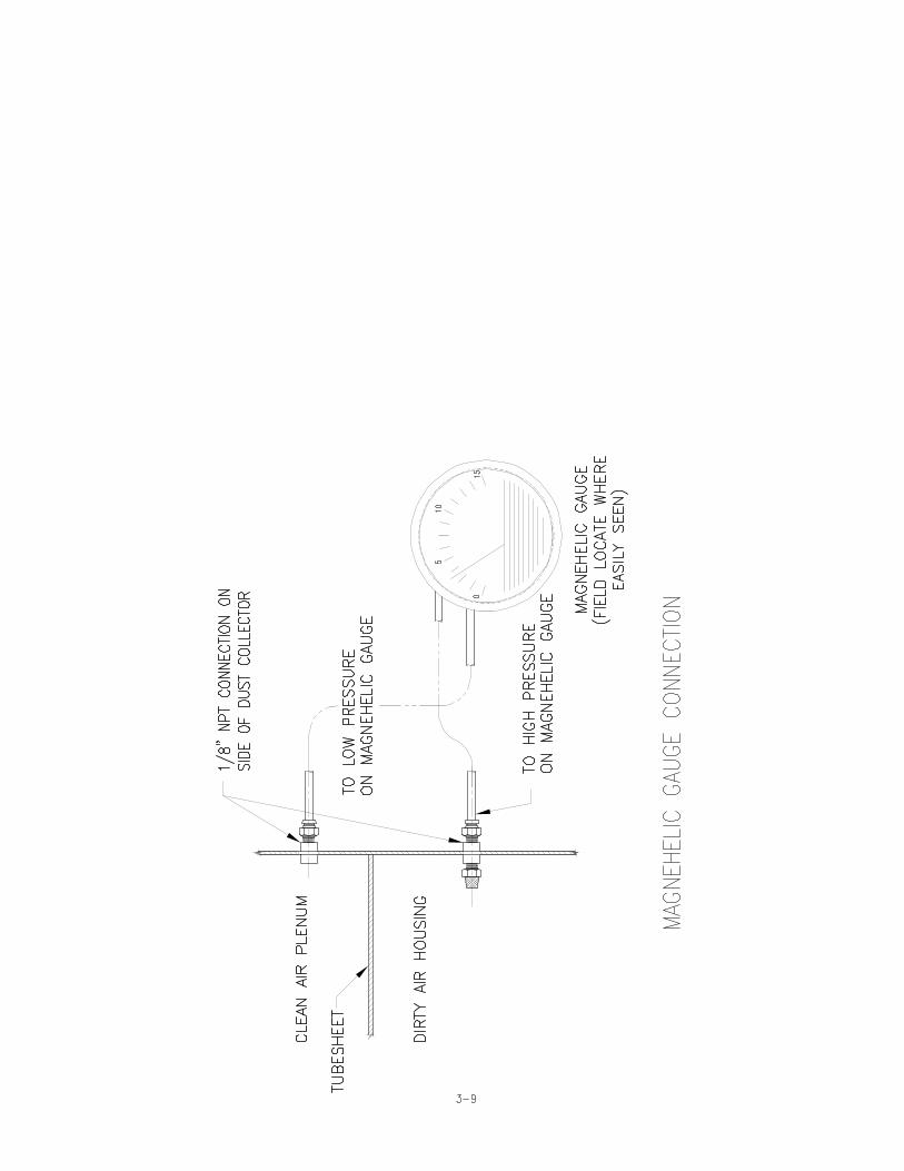
Operating Principle
A. Solids laden air or gases enter the unit at the hopper or housing inlet. B. Air passes through the filter media. C. Solids are retained on the filter media surface. D. Cleaning cycle consists of a momentary blast of 90-100 psig
compressed air: 1. Momentarily taking a row of bags off stream through
pressure reversal. 2. Flexing filter bags. 3. Solids are released to fall towards hopper and through rotary
valve or other discharge equipment.
CAMCORP, INC. Phone: 913-831-0740 Fax: 913-831-9271
www.camcorpinc.com
4-1

CAMCORP, INC. Phone: 913-831-0740 Fax: 913-831-9271
www.camcorpinc.com
Start-Up Checklist
Installation
Make sure the unit is secured to the floor or mounting surface. The ladder(s) and platform(s) must be tightened and set up according to OSHA requirements. Ducting and piping must be secured and routed out of the way of traffic whenever possible to avoid injury. Ducting must also be free of all debris including moisture.
Interior of Dirty Air Plenum
In a bottom bag removal collector, inspect the filter bag assemblies referring to the “Bag and Cage Installation” section of this manual. Improperly installed bags may allow dusty air to enter the clean air plenum.
High-level indicator, if so equipped, should be connected below the material inlet(s) to avoid over filling the hopper.
Interior of Clean Air Plenum
The blowholes in the blowpipes must be centered over the filter bags.
On top bag removal collectors verify that bags and cages are properly installed. On top bag removal collectors the bulkhead fittings must be checked for proper tightness and that the blowpipes are secured at both ends.
Exterior of Dust Collector
Access doors, inspection ports and spring-loaded relief vents should seat effectively to prevent leakage.
All bolts must be properly tightened. Operate any equipment connected to the dust discharge of the dust collector. Check the rotation of any motor driven equipment such as rotary airlocks, horizontal unloading valves, live bottom bin activators and screw conveyors. Check slide gates and butterfly valves for binding.
4-2

CAMCORP, INC. Phone: 913-831-0740 Fax: 913-831-9271
www.camcorpinc.com
Start-Up Checklist (continued)
Explosion Relief Panels – Shear Bolt Style (when used)
Inspect explosion relief vents (when used) for broken or damaged explosion bolts. ASSURE THAT THERE ARE NO STEEL BOLTS USED FOR THE INSTALLATION OF THE EXPLOSION RELIEF PANEL!!! These bolts are made of special high tech poly-vinyl chloride and are designed to relieve at a specific pressure. A magnet should be used to check for steel bolts.
Explosion Relief Panels – Rupture Style (when used)
Inspect explosion relief vents for cracks and that all mounting bolts are tight.
Compressed Air System
The pulse timer board must be correctly wired and mounted in its enclosure in a suitable location.
All the ¼” copper or nylon tubing connections between the diaphragm and the solenoid valves must be tight and the tubing must not be crimped.
The plugs (when used) must be removed from the exhaust ports of the solenoid valves and the tubing from the diaphragm valves must be connected to the “IN” port on the solenoid valves.
The compressed air supply system must be equipped to supply clean, dry air to the pulsing air system. At this time assure that there is a suitable air pressure gauge on the air header for reading 0-160 psig.
Start the compressed air supply system and check for air leaks in all parts of the system. If air is heard escaping through one or more of the blowpipes (with the timer off), please refer to the “Troubleshooting the Compressed Air System” section of this manual. Gauge pressure at the compressed air manifold(s) should be 90-100 psig.
4-3

CAMCORP, INC. Phone: 913-831-0740 Fax: 913-831-9271
www.camcorpinc.com
Start-Up Checklist (continued)
With the compressed air system operating, energize the timer board to begin pulsing. Check to see that all solenoids are firing by placing a finger over the exhaust port of one of the solenoid valves. When the solenoid valve being checked is energized by an electrical pulse from the timer board the finger at the exhaust port should feel a short blast of air. Quickly move to the next solenoid valve in the firing order noting any valves that do not fire or are stuck open causing a continuous airflow out of the exhaust port of the valve. At this time note the quality of the compressed air. It should be clean, dry, and oil free.
Allow the compressed air system to operate as long as possible to clear the system of dirt, rust, scale, welding slag and metal chips that can cause the diaphragm valves to stick.
The pressure at the compressed air manifold must recover to 90-100 psig before each pulse. Make sure that there is adequate compressed air delivery for full pressure recovery when all other systems connected to the same air supply are operating at full capacity.
4-4

CAMCORP, INC. Phone: 913-831-0740 Fax: 913-831-9271
www.camcorpinc.com
Start-Up Dust Control Systems
Fan or Blower System
Start the fan or blower and check for proper rotation.
Check dust pickup points for proper suction. Balance airflow in individual ducts.
Check for air leakage at all flanged connections.
Equipment Start-Up Sequence
The compressed air supply system must be started first.
When the pressure gauge on the compressed air manifold indicates that the system is at full pressure (90-100psig) the pulse timer can be energized.
Dust take away equipment such as rotary airlocks, screw conveyors, horizontal unloading valves, live bottom bin activators and pneumatic conveying systems can now be started in their correct sequence.
Check that all access doors, hatches, ports, and other openings are closed and latched or bolted.
The main exhaust fan can now be started and brought up to speed.
Start the dust-laden air through the collector. The collector should be started under partial load to allow the bags to become slowly and evenly coated with dust particles.
On pneumatic conveying systems watch the differential pressure gauge closely for the first hour or so. If unstable, the collector discharge system may be too small for the volume it is seeing. A quick fix is to reduce the material feed until the discharge rate can be increased.
Observe the manometer or magnahelic differential pressure gauge reading. As the new filter bags become coated with dust, the efficiency of the filtering action increases and the differential pressure across the filter bags will also increase. Slowly bring the collector to full load and note the final pressure drop across the filter bags. Never allow the pressure drop across the filter bags to exceed 17” w.g. maximum or the filter bags may collapse.
4-5

CAMCORP, INC. Phone: 913-831-0740 Fax: 913-831-9271
www.camcorpinc.com
Start-Up Dust Control Systems (continued)
Note: If the pressure drop continues to increase over 5” w.g. and does
not stabilize, decrease the timer “off time” to fifteen seconds. Should adjustment of the timer “off time” fail to cause the pressure drop to stabilize below 5” w.g., shut down the collector and refer to “Troubleshooting the Collector” or call your CAMCORP representative.
When the collector has stabilized the timer “off time” interval may be slowly increased for the most economical use of compressed air. As the “off time” is increased, the differential pressure will also increase. Readings up to 6” w.g. are acceptable, however we recommend operating at 3”-4” w.g. for maximum filter bag life. The timer “off time” may be decreased when lower differential pressure readings are desired. When adjusting the “off time” interval proceed in small steps allowing the differential pressure to stabilize for several hours between adjustments.
Check the main airflow with a pitot tube or equivalent measuring device to establish initial conditions. If the main airflow must be adjusted up or down to suit the process, repeat the steps above.
Shutdown Procedures
Dust control systems
Reverse start-up procedure, shut down fan, then after a 5 or 10-minute delay, shut down the timer and discharge system.
Pneumatic systems
Reverse start-up procedure, shut down fan, then after 5 or 10 minute delay, shut down the timer and discharge system.
4-6

CAMCORP, INC.
Phone: 913-831-0740 Fax: 913-831-9271
www.camcorpinc.com
Section 5 - Component Information
The following pages show details of the mechanical and electrical components of a typical dust collector. Below is information for identifying each component and repair kit if applicable.
Dwyer Magnehelic Differential Pressure Gauge Camcorp part number 400031 – Range: - 15” w.c.
Timers – National Controls Corp. (Camcorp standard) Replacement Timer Boards Only.
Camcorp P/N Call Camcorp – NCC # DNC-T2003-020 (3 Outputs) Camcorp P/N Call Camcorp – NCC # DNC-T2006-020 (6 Outputs) Camcorp P/N Call Camcorp – NCC # DNC-T2010-020 (10 Outputs) Camcorp P/N Call Camcorp – NCC # DNC-T2020-020 (20 Outputs) Camcorp P/N Call Camcorp – NCC # DNC-T2032-020 (32 Outputs)
Timers – Dwyer Instruments Smart Timers (Optional) Replacement Timer Boards Only (Does not include pressure module)
Camcorp P/N 400028 – Dwyer # DCT-1006 (6 Outputs) Camcorp P/N 400029 – Dwyer # DCT-1010 (10 Outputs) Camcorp P/N (call) – Dwyer DCP100 (0-10” Pressure Module)
Diaphragm Valves (Compression Coupling Ends) - Goyen Camcorp P/N 400001 – Goyen # RCA20DD (3/4” Valve) Camcorp P/N 400002 – Goyen # RCA25DD (1” Valve) Camcorp P/N 400003 – Goyen # RCA45DD (1 1/2” Valve) Camcorp P/N 400008 - Repair Kit Goyen # G-20 (3/4” Valve) Camcorp P/N 400009 – Repair Kit Goyen # G-25 (1” Valve) Camcorp P/N 400010 – Repair Kit Goyen # G-45 (1 1/2” Valve)
Solenoid Valves – NEMA 4 / 120VAC – Goyen Camcorp P/N 400043 – Goyen #RCA3-5V3000-331 (3 Valves) Camcorp P/N 400044 – Goyen #RCA3-5V4000-331 (4 Valves) Camcorp P/N 400065 – Goyen #RCA3-5V5000-331 (5 Valves) Camcorp P/N 400059 – Goyen #RCA3-8V6000-331 (6 Valves) Camcorp P/N 400058 – Goyen #RCA3-8V7000-331 (7 Valves) Camcorp P/N 400070 – Goyen #RCA3-8V8000-331 (8 Valves) Camcorp P/N 400056 – Goyen #RCA3-12V9000-331 (9 Valves) Camcorp P/N 400045 – Goyen #RCA3-12V10000-331 (10 Valves) Camcorp P/N 400020 – Repair Kit Goyen # K0380 (1/8” Solenoid)
5-1

CAMCORP, INC. Phone: 913-831-0740 Fax: 913-831-9271
www.camcorpinc.com
Explosion Vents (if applicable) - Confirm Vent(s) with Camcorp Camcorp P/N 400068 – 18”x35” Flat Vent, 1.5 PSI Burst Camcorp P/N 400105 – 18”x35” Domed Vent, 1.5 PSI Burst Camcorp P/N 400067 – 36”x36” Flat Vent, 1.5 PSI Burst Camcorp P/N 400096 – 36”x36” Domed Vent, 1.5 PSI Burst
The parts above are supplied as standard components on a Camcorp dust collector. If you require high temperature components, NEMA 7/9 electrical components, 24VDC or 220VAC components, etc. please contact Camcorp for the correct parts.
5-2

SPECIFICATIONSDimensions: 4-3/4" dia. X 2-3/16" deep.Weight: 1 lb. 2 oz.Finish: Baked dark gray enamel.Connections: 1/8 N.P.T high and low pressure
taps, duplicated, one pair side and onepair back.
Accuracy: Plus or minus 2% of full scale, at70°F. (Model 2000-0, 3%; 2000-00, 4%).
Pressure Rating: 15 PSI.Ambient Temperature Range: 20° to 140°FStandard gage accessories include two 1/8"
N.P.T. plugs for duplicate pressure taps,two 1/8" pipe thread to rubber tubingadapters, and three flush mountingadapters with screws.
Caution: For use with air or compatible gasesonly.
For repeated over-ranging or high cycle rates,contact factory.
Hydrogen Gas Precautionary Note: The rec-tangular rare earth magnet used in thestandard gage may not be suitable foruse with hydrogen gas since a toxic andexplosive gas may form. For hydrogenservice, consult the factory for an alter-nate gage construction.
B U L L E T I N N O . A-27OPERATING INSTRUCTIONS and PARTS LIST
Magnehelic® Differential Pressure Gage
DWYER INSTRUMENTS, INC.P.O. BOX 373 • MICHIGAN CITY, INDIANA 46360, U.S.A.
Telephone 219/879-8000Fax 219/872-9057Lit-by-fax: 888/891-4963
www.dwyer-inst.come-mail: [email protected]
MAGNEHELIC® INSTALLATION
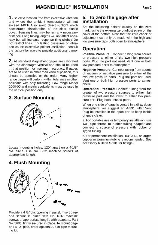
1. Select a location free from excessive vibrationand where the ambient temperature will notexceed 140°F Also, avoid direct sunlight whichaccelerates discoloration of the clear plasticcover. Sensing lines may be run any necessarydistance. Long tubing lengths will not affect accu-racy but will increase response time slightly. Donot restrict lines. If pulsating pressures or vibra-tion cause excessive pointer oscillation, consultthe factory for ways to provide additional damp-ing.
2. All standard Magnehelic gages are calibratedwith the diaphragm vertical and should be usedin that position for maximum accuracy. If gagesare to be used in other than vertical position, thisshould be specified on the order. Many higherrange gages will perform within tolerance in otherpositions with only rezeroing. Low range Model2000-00 and metric equivalents must be used inthe vertical position only.
3. Surface Mounting
Locate mounting holes, 120° apart on a 4-1/8"dia. circle. Use No. 6-32 machine screws ofappropriate length.
4. Flush Mounting
Provide a 4 9⁄16" dia. opening in panel. Insert gageand secure in place with No. 6-32 machinescrews of appropriate length, with adaptors, PartNo. 360c, firmly secured in place. To mount gageon I 1⁄4"-2" pipe, order optional A-610 pipe mount-ing kit.
5. To zero the gage afterinstallationSet the indicating pointer exactly on the zeromark, using the external zero adjust screw on thecover at the bottom. Note that the zero check oradjustment can only be made with the high andlow pressure taps both open to atmosphere.
OperationPositive Pressure: Connect tubing from sourceof pressure to either of the two high pressureports. Plug the port not used. Vent one or bothlow pressure ports to atmosphere.
Negative Pressure: Connect tubing from sourceof vacuum or negative pressure to either of thetwo low pressure ports. Plug the port not used.Vent one or both high pressure ports to atmos-phere.
Differential Pressure: Connect tubing from thegreater of two pressure sources to either highpressure port and the lower to either low pres-sure port. Plug both unused ports.
When one side of gage is vented in a dirty, dustyatmosphere, we suggest an A-331 Filter VentPlug be installed in the open port to keep insideof gage clean.
a. For portable use or temporary installation, use1/8" pipe thread to rubber tubing adapter andconnect to source of pressure with rubber orTygon tubing.
b. For permanent installation, 1/4" 0. D., or larger,copper or aluminum tubing is recommended. Seeaccessory bulletin S-101 for fittings.
Page 2
MAINTENANCEBULLETIN NO. A-27
Page 3
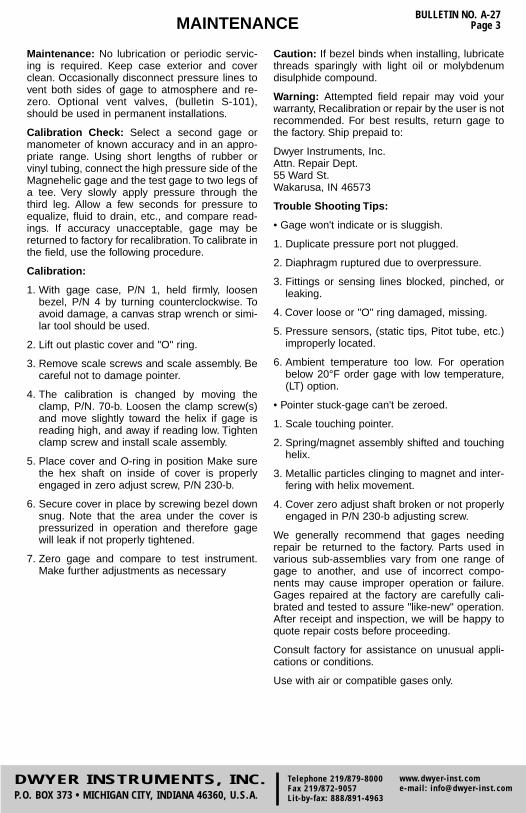
Maintenance: No lubrication or periodic servic-ing is required. Keep case exterior and coverclean. Occasionally disconnect pressure lines tovent both sides of gage to atmosphere and re-zero. Optional vent valves, (bulletin S-101),should be used in permanent installations.
Calibration Check: Select a second gage ormanometer of known accuracy and in an appro-priate range. Using short lengths of rubber orvinyl tubing, connect the high pressure side of theMagnehelic gage and the test gage to two legs ofa tee. Very slowly apply pressure through thethird leg. Allow a few seconds for pressure toequalize, fluid to drain, etc., and compare read-ings. If accuracy unacceptable, gage may bereturned to factory for recalibration. To calibrate inthe field, use the following procedure.
Calibration:
1. With gage case, P/N 1, held firmly, loosenbezel, P/N 4 by turning counterclockwise. Toavoid damage, a canvas strap wrench or simi-lar tool should be used.
2. Lift out plastic cover and "O" ring.
3. Remove scale screws and scale assembly. Becareful not to damage pointer.
4. The calibration is changed by moving theclamp, P/N. 70-b. Loosen the clamp screw(s)and move slightly toward the helix if gage isreading high, and away if reading low. Tightenclamp screw and install scale assembly.
5. Place cover and O-ring in position Make surethe hex shaft on inside of cover is properlyengaged in zero adjust screw, P/N 230-b.
6. Secure cover in place by screwing bezel downsnug. Note that the area under the cover ispressurized in operation and therefore gagewill leak if not properly tightened.
7. Zero gage and compare to test instrument.Make further adjustments as necessary
Caution: If bezel binds when installing, lubricatethreads sparingly with light oil or molybdenumdisulphide compound.
Warning: Attempted field repair may void yourwarranty, Recalibration or repair by the user is notrecommended. For best results, return gage tothe factory. Ship prepaid to:
Dwyer Instruments, Inc.Attn. Repair Dept.55 Ward St.Wakarusa, IN 46573
Trouble Shooting Tips:
• Gage won't indicate or is sluggish.
1. Duplicate pressure port not plugged.
2. Diaphragm ruptured due to overpressure.
3. Fittings or sensing lines blocked, pinched, orleaking.
4. Cover loose or "O" ring damaged, missing.
5. Pressure sensors, (static tips, Pitot tube, etc.)improperly located.
6. Ambient temperature too low. For operationbelow 20°F order gage with low temperature,(LT) option.
• Pointer stuck-gage can't be zeroed.
1. Scale touching pointer.
2. Spring/magnet assembly shifted and touchinghelix.
3. Metallic particles clinging to magnet and inter-fering with helix movement.
4. Cover zero adjust shaft broken or not properlyengaged in P/N 230-b adjusting screw.
We generally recommend that gages needingrepair be returned to the factory. Parts used invarious sub-assemblies vary from one range ofgage to another, and use of incorrect compo-nents may cause improper operation or failure.Gages repaired at the factory are carefully cali-brated and tested to assure "like-new" operation.After receipt and inspection, we will be happy toquote repair costs before proceeding.
Consult factory for assistance on unusual appli-cations or conditions.
Use with air or compatible gases only.
DWYER INSTRUMENTS, INC.P.O. BOX 373 • MICHIGAN CITY, INDIANA 46360, U.S.A.
Telephone 219/879-8000Fax 219/872-9057Lit-by-fax: 888/891-4963
www.dwyer-inst.come-mail: [email protected]

BULLETIN NO. A-27Page 4
Magnehelic® GageEXPLODED VIEW
Series 2000
Ordering Instructions:When corresponding with the factory regarding Magnehelic® gage problems, refer to thecall-out numbers in this view. Be sure to include model number, pressure range, and anyspecial options. Field repair is not recommended; contact the factory for repair serviceinformation.
©Copyright 1993 Dwyer Instruments, Inc. Printed in U.S.A. 6/93 12-440212-00
1. Case2. Cover with zero adjust assy.3. "O" ring seal4. Bezel5. Diaphragm sealing plate6. Retaining ring
70. Range Spring assemblya. Clamp set screwb. Clampc. Mounting screws (2 req'd)d. Clamping shoe (2 req'd)e. Clamp plate screwf. Spacer (2 req'd)
g. Clamp plate14. Range Spring with magnet
150. Wishbone Assembly -consists of:a. Front jewelb. Locking nutc. Wishboned. Pointere. Mounting screws (2 req'd)f. Helix assembly (not shown)g. Pivots (2 req'd) (not shown)h. Rear jewel (not shown)
230. Zero adjust assembly-consists of:a. Foot screws with washers (2 req'd)b. Adjust screwc. Footd. Finger
260. Scale Assembly-consists of:a. Mounting screws (2 req'd)b. Bumper pointer stop (2 req'd)c. Scale
330. Diaphragm Assembly -consists of:(Arbor press needed to install)
a. linkage assy., complete b. Front plate c. Diaphragm d. Rear plate (not shown) e. Plate washer (not shown)
360. Mounting Hardware Kit a. Adapter -pipe plug 1/8" NPT to
rubber tubing - (2 req'd) b. Pipe plug 1/8" NPT-(2 req'd) c. Mounting lug (3 req'd) d. Long screw (3 req'd) e. Short screw (3 req'd)

AMETEK National Controls Corp. • 1725 Western Drive • West Chicago, Illinois 60185 • Tel: 800-323-2593 • 630-231-5900 • FAX: 630-231-1377 • www.nationalcontrols.com
IFCB DUST COLLECTOR CONTROLS
AC Input, Pulse Cleaning of Bag House Dust Collectors Models DNC-T2003 through DNC-T2032FEATURES
● Universal voltage input: 95 to 265 VAC 50/60 Hz
● One SKU: covers all voltages and time ranges required in your application
● Advanced surface mount component technology: extremely reliable and trou-ble free operation
● Digital microprocessor controlled cir-cuitry: for precise pulse timing
● Non-Volatile memory: for retaining pro-grammed settings
● 3 digit, 7 segment numeric display: for ease of viewing controller operation
● Easily programmable: on/off times and last output used via keypad
● Small footprint: same size for 3, 6 and 10 output control
● Time Ranges for all applications: On Time: 50ms to 600 sec, Off time: 1 to 999 sec
● 2 modes of operation: can be operated continuously or on demand via external pressure switch
● Finger safe terminations: reliable elec-trical connections and increases safety
● RoHS construction: suited for global applications
● Supplied on metal chassis: for mount-ing directly in a NEMA 4 box
● Retrofit models available: for direct drop in replacement of former product
● UL/CUL: File # E65038
OPERATING LOGIC The DNC-T2003 through DNC-T2032 con-trols are output sequencers with an ad justable ON TIME, OFF TIME, and LAST OUTPUT. Upon application of power to the L1 and L2 terminals with the high pres-sure switch co ntacts c losed, the OFF TIME is initiated. At the end o f the preset OFF TIME, output 1will turn on for the pre-set ON TIME. The control will cycle through all selected outputs until the high and low pressure switch contacts are opened. If the pressure switch contacts open dur-ing the ON TIME, the output will complete the active ON cycle. The next time the high pressure switch is closed the next output in the sequence is fired. Pressure monitoring with no hysteresis is achieved by using only
a high pressure switch. Placing a jumper across the high pressure input forces the control to run continuously.Note: Controls are shipped with jumper across pressure switch terminals
PROGRAMMINGProgramming is accomplished using 3 buttons: down, up, and selectDown: Decrements the active parameterUp: Increments the active parameterSelect: Toggles amongst the adjustable parameters: on-time, off-time, and last outputProgramming Mode Timeout: 60 seconds
TEST & DEFAULT MODESTest mode is entered by pressing and hold-ing the select button for 3 seconds while the unit is in the normal operating mode. Once in test mode, the display will show tSt. Pressing the up or down arrow buttonstoggles amongst outputs, and pressing select pulses the selected output for the preset ON-TIME. Pressing the select button while the display shows tSt will change the display to “dFt”. While the display shows“dFt”, the up and down arrows toggle amongst “y”, “n”, and “dFt”. Pressing select when the message is “y” will set all ad just-able parameters to the factory defaults. At any time in test and default modes, pressing and holding the select button for 1.5 sec-onds will revert the controller back to the normal operating mode.
Timer No. 1
Pressure Switch
Note: Must connect L1 of first unit to L1 of second unit. Same with L2.
Outputs 10
HI CM LO HI CM LO
Timer No. 2
Pressure Switch
Outputs 10
Last output used
Last output used
Last Solenoid
120 VAC
Last Solenoid
LatchLatch
120 VAC
Alternate — ActionLatching Relay
S S
“A” “A”
“B”“B”
L1L2 L1L2

IFCC
AMETEK National Controls Corp. • 1725 Western Drive • West Chicago, Illinois 60185 • Tel: 800-323-2593 • 630-231-5900 • FAX: 630-231-1377 • www.nationalcontrols.com
DUST COLLECTOR CONTROLS
Pressure switch supplied by customer(Unit is shipped with jumper across “Hi” pressure switch terminal block)
.050 THKAluminumChassis
.362 Max
1.103Max
.250 DIA. Hole 4 Plcs3.15A Fuse
.250Typ
A
B
BD
E
GNDL1L2
ORDERING INFORMATION
Caution:1. Do not mount controls in high vibration areas without shock mounts.2. Do not mount controls in areas of high dust or corrosive atmospheres without a protective enclosure.3 Do not use a converter or inverter for the power source.4. Do not mount control in high transient voltage areas without an isolation transformer.5. Do not leave control box open. 6. Do not allow a local repair shop to repair the controls, as we employ some very sophisticated components that could be further damaged. For service, call us directly: 800-323-2593.
ModelDNC–T2003–020
Max. No. of Outputs3
Dimensions - InchSize of NEMA 4 Enclosure Reqd.A B C D E
DNC–T2003–020 3 6.75” 4.75” 6.25” 4.25” .250” 8” X 6” X 3.5”
DNC–T2006–020 6 6.75” 4.75” 6.25” 4.25” .250” 8” X 6” X 3.5”
DNC–T2010–020 10 6.75” 4.75” 6.25” 4.25” .250” 8” X 6” X 3.5”
DNC–T2020–020 20 8.75” 7.00” 8.25” 6.25” .375” 10” X 8” X 4”
DNC–T2032–020 32 8.75” 7.00” 8.25” 6.25” .375” 10” X 8” X 4”
DNC–T2006–R20 6 8.75” 6.875” 8.25” 6.25” .313” 10” X 8” X 4”
DNC–T2010–R20 10 8.75” 6.875” 8.25” 6.25” .313” 10” X 8” X 4”
DNC–T2020–R20 20 10.75” 8.875” 10.25” 8.25” .312” 12” X 10” X 5”
DNC–T2032–R20 32 12.75” 10.875” 12.126” 10.251” .312” 14” X 12” X 6”
SPECIFICATIONSINPUT:Input Voltage: 95 – 265 VAC 50/60 HzPower Consumption: 6.30 VA max plus loadCircuit Protection: 3.15A fast acting fuse and 72J metal-oxide varistor at inputOUTPUT:Output: Solid state, 150VA maxOff State Leakage 1.5mA maxOn State Voltage Drop: 1.5V maxENVIRONMENTAL:Operating Temperature: -40 to +150 F (-40 to +66 C) Conformally coated with RTV to protect against moisture, corrosion, and vibrationDISPLAY:Display: 3 digit, 7 segment, green LEDIndicator LEDs: 5 green SMT (power, cleaning, on time, off time, last output)TIME DELAY:On Time: 50 milliseconds – 600 secondsOff Time: 1 – 999 secondsResolution: 10ms (50ms – 1 0 sec), 100ms (10sec – 100sec), 1sec (100sec – 600sec)Accuracy and Repeatability: ±3% over tempera-ture and voltage rangeDefault Settings:On Time: 50 millisecondsOff Time: 15 secondsLast Output: Max. No. of Outputs

Specifications – Installation and Operating Instructions
BULLETIN E-97
Series DCT1000 Dust Collector Timer Controller
Thank you for purchasing the DCT1000 Dust Collector TimerController. You have selected a state of the art dust collectortimer control that will provide years of dependable operationand service.
The DCT1000 Dust Collector Timer Controller was designedto be used with pulse-jet type dust collectors for on-demandor continuous cleaning applications. The DCT1000 consistsof three basic modules: the master controller, the optionalchannel expander (slave board) and the pressure module(DCP100/200). This manual is limited to the installation andoperation of the master controller and optional channelexpander. For installation requirements on the pressure mod-ule, please refer to the installation and operating instructionsfor the DCP100/200. Continuous cleaning applications do not require externalinputs and can be used for time based “on-demand” clean-ing through use of the cycle delay feature.For on-demand applications, the plug-in pressure modules(DCP100/200) can be used to take full advantage of all thefeatures the DCT1000 offers, or an external pressure switch(such as the Dwyer Photohelic®) can be used for High/Lowlimit control.
As with traditional Dwyer products, the Dwyer DCT1000 wasdesigned so that it is easy to use, thus allowing for a quickand easy start up for your dust control applications. The con-tents inside this installation and operating manual will guideyou through the features of the DCT1000 and how they canbe applied to get the most out of your dust control require-ments.
DWYER INSTRUMENTS, INC.P.O. BOX 373 • MICHIGAN CITY, INDIANA 46361 U.S.A.
PHYSICAL DATAStorage Temperature: -40˚F to 176˚F (-40˚C to 80˚C).Operating Ambient Temperature: -40˚F to 140˚F (-40˚C to60˚C).Weight: 1 lb. 3.0 oz. (538.6 grams).Power: 50 or 60 Hz, 85 to 270 VAC input. Power input: 270 VAC RMS max., transients: 80 Joule @1000 msec/50 Joule @ 2 msec.Fuse: 3A @ 250 VAC.Low voltage control circuitry is isolated from the line voltage forsystem safety.Output Channels: up to 22 on one module, expandable to255 using additional expansion modules.Solenoid supply: 300 VA max.On-time: 10 msec to 600 msec, 10 msec steps.On-time Accuracy: ±10 msec.Off-time: 1 to 255 seconds, in 1 second steps.Off-time Accuracy: ±1% of the value or ±50 msec, whichever is greater.
Default Settings:Channels: All installed channelsTime-off: 10 secondsTime-on: 100 msec.Down-time Cycles: 1 minuteCycle Delay: 0 minutes.Low Alarm: 1.0″ w.c. [0.25 kPa]High Alarm: 6.0″ w.c. [1.49 kPa]Low Limit: 3.0″ w.c. [0.75 kPa]High Limit: 5.0″ w.c. [1.24 kPa]Auto Alarm Reset: 5 seconds.
Phone: 219/879-8000 www.dwyer-inst.comFax: 219/872-9057 e-mail: [email protected]: 888/891-4963
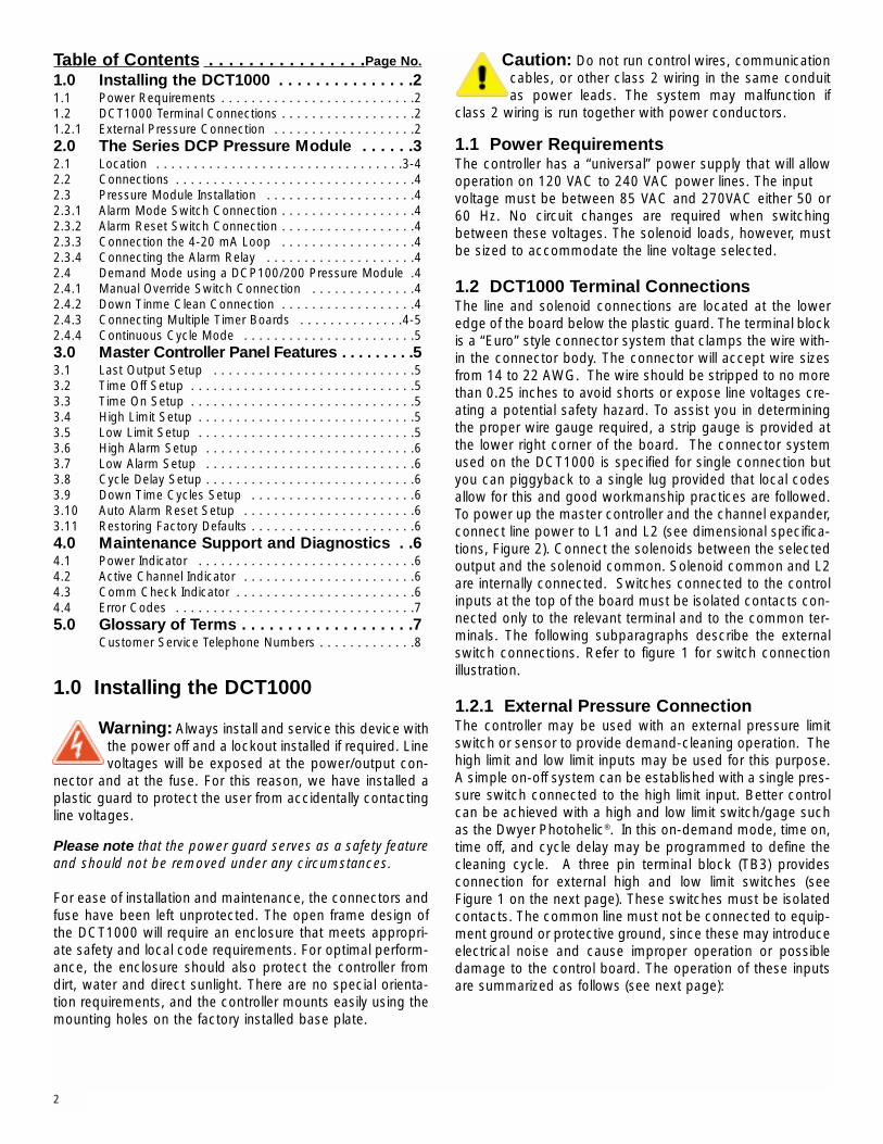
Table of Contents . . . . . . . . . . . . . . . .Page No.
1.0 Installing the DCT1000 . . . . . . . . . . . . . . .21.1 Power Requirements . . . . . . . . . . . . . . . . . . . . . . . . . .21.2 DCT1000 Terminal Connections . . . . . . . . . . . . . . . . . .21.2.1 External Pressure Connection . . . . . . . . . . . . . . . . . . .22.0 The Series DCP Pressure Module . . . . . .32.1 Location . . . . . . . . . . . . . . . . . . . . . . . . . . . . . . . . .3-42.2 Connections . . . . . . . . . . . . . . . . . . . . . . . . . . . . . . . .42.3 Pressure Module Installation . . . . . . . . . . . . . . . . . . . .42.3.1 Alarm Mode Switch Connection . . . . . . . . . . . . . . . . . .42.3.2 Alarm Reset Switch Connection . . . . . . . . . . . . . . . . . .42.3.3 Connection the 4-20 mA Loop . . . . . . . . . . . . . . . . . .42.3.4 Connecting the Alarm Relay . . . . . . . . . . . . . . . . . . . .42.4 Demand Mode using a DCP100/200 Pressure Module .42.4.1 Manual Override Switch Connection . . . . . . . . . . . . . .42.4.2 Down Tinme Clean Connection . . . . . . . . . . . . . . . . . .42.4.3 Connecting Multiple Timer Boards . . . . . . . . . . . . . .4-52.4.4 Continuous Cycle Mode . . . . . . . . . . . . . . . . . . . . . . .53.0 Master Controller Panel Features . . . . . . . . .53.1 Last Output Setup . . . . . . . . . . . . . . . . . . . . . . . . . . .53.2 Time Off Setup . . . . . . . . . . . . . . . . . . . . . . . . . . . . . .53.3 Time On Setup . . . . . . . . . . . . . . . . . . . . . . . . . . . . . .53.4 High Limit Setup . . . . . . . . . . . . . . . . . . . . . . . . . . . . .53.5 Low Limit Setup . . . . . . . . . . . . . . . . . . . . . . . . . . . . .53.6 High Alarm Setup . . . . . . . . . . . . . . . . . . . . . . . . . . . .63.7 Low Alarm Setup . . . . . . . . . . . . . . . . . . . . . . . . . . . .63.8 Cycle Delay Setup . . . . . . . . . . . . . . . . . . . . . . . . . . . .63.9 Down Time Cycles Setup . . . . . . . . . . . . . . . . . . . . . .63.10 Auto Alarm Reset Setup . . . . . . . . . . . . . . . . . . . . . . .63.11 Restoring Factory Defaults . . . . . . . . . . . . . . . . . . . . . .64.0 Maintenance Support and Diagnostics . .64.1 Power Indicator . . . . . . . . . . . . . . . . . . . . . . . . . . . . .64.2 Active Channel Indicator . . . . . . . . . . . . . . . . . . . . . . .64.3 Comm Check Indicator . . . . . . . . . . . . . . . . . . . . . . . .64.4 Error Codes . . . . . . . . . . . . . . . . . . . . . . . . . . . . . . . .75.0 Glossary of Terms . . . . . . . . . . . . . . . . . . .7
Customer Service Telephone Numbers . . . . . . . . . . . . .8
1.0 Installing the DCT1000
Warning: Always install and service this device withthe power off and a lockout installed if required. Linevoltages will be exposed at the power/output con-
nector and at the fuse. For this reason, we have installed aplastic guard to protect the user from accidentally contactingline voltages.
Please note that the power guard serves as a safety featureand should not be removed under any circumstances.
For ease of installation and maintenance, the connectors andfuse have been left unprotected. The open frame design ofthe DCT1000 will require an enclosure that meets appropri-ate safety and local code requirements. For optimal perform-ance, the enclosure should also protect the controller fromdirt, water and direct sunlight. There are no special orienta-tion requirements, and the controller mounts easily using themounting holes on the factory installed base plate.
Caution: Do not run control wires, communicationcables, or other class 2 wiring in the same conduitas power leads. The system may malfunction if
class 2 wiring is run together with power conductors.
1.1 Power RequirementsThe controller has a “universal” power supply that will allowoperation on 120 VAC to 240 VAC power lines. The input voltage must be between 85 VAC and 270VAC either 50 or60 Hz. No circuit changes are required when switchingbetween these voltages. The solenoid loads, however, mustbe sized to accommodate the line voltage selected.
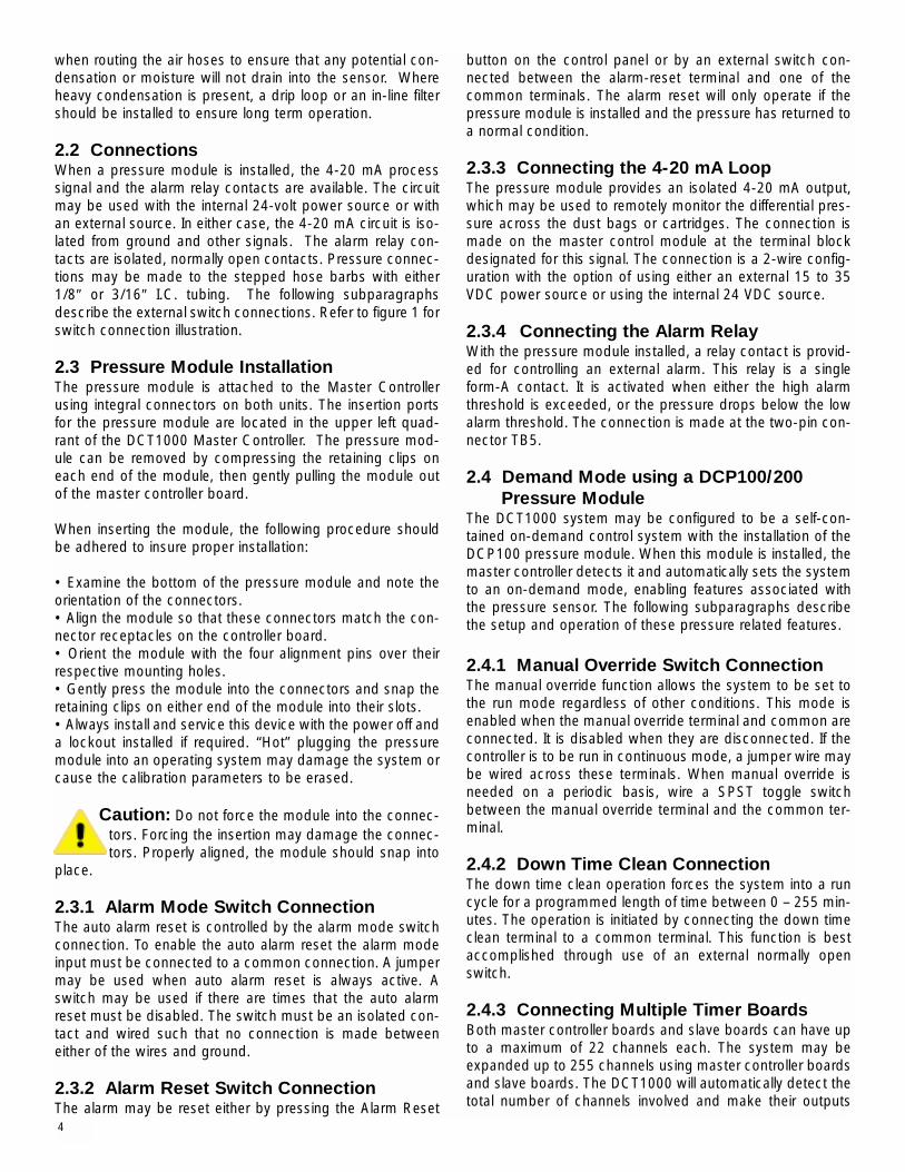
1.2 DCT1000 Terminal ConnectionsThe line and solenoid connections are located at the loweredge of the board below the plastic guard. The terminal blockis a “Euro” style connector system that clamps the wire with-in the connector body. The connector will accept wire sizesfrom 14 to 22 AWG. The wire should be stripped to no morethan 0.25 inches to avoid shorts or expose line voltages cre-ating a potential safety hazard. To assist you in determiningthe proper wire gauge required, a strip gauge is provided atthe lower right corner of the board. The connector systemused on the DCT1000 is specified for single connection butyou can piggyback to a single lug provided that local codesallow for this and good workmanship practices are followed.To power up the master controller and the channel expander,connect line power to L1 and L2 (see dimensional specifica-tions, Figure 2). Connect the solenoids between the selectedoutput and the solenoid common. Solenoid common and L2are internally connected. Switches connected to the controlinputs at the top of the board must be isolated contacts con-nected only to the relevant terminal and to the common ter-minals. The following subparagraphs describe the externalswitch connections. Refer to figure 1 for switch connectionillustration.
1.2.1 External Pressure ConnectionThe controller may be used with an external pressure limitswitch or sensor to provide demand-cleaning operation. Thehigh limit and low limit inputs may be used for this purpose.A simple on-off system can be established with a single pres-sure switch connected to the high limit input. Better controlcan be achieved with a high and low limit switch/gage suchas the Dwyer Photohelic®. In this on-demand mode, time on,time off, and cycle delay may be programmed to define thecleaning cycle. A three pin terminal block (TB3) providesconnection for external high and low limit switches (seeFigure 1 on the next page). These switches must be isolatedcontacts. The common line must not be connected to equip-ment ground or protective ground, since these may introduceelectrical noise and cause improper operation or possibledamage to the control board. The operation of these inputsare summarized as follows (see next page):
2

4-20 mA ConnectionsReceiver
Using DCT100024V Supply
LowLimit
HighLimit
PressureLimitSwitches
+ -
Receiver+ -Optional ConnectionUsing ExternalPower Supply
+Supply
-
Supply AlarmLoad
4-20 mA Connections
TB4
HighLimit Com Low
Limit
TB3
TB5AlarmRelayContacts
TB1(Internally Connected)
Master Controller
(10 Channel Shown)
Com ComAlarmMode
ManOvr
DtCln
AlarmReset
TB3
Dai
sy C
hain
In
O
ut
Dai
sy C
hain
In
O
ut
Master ControllerInput MUST NOTBe Connected
To AdditionalExpanderModules
(10 Channel Shown)
Slave Channel ExpanderLineInput Solenoids
SolComL1 L2 1 2 3 4 5 6 7 8 9 10
SolComL1 L2 1 2 3 4 5 6 7 8 9 10
LineInput Solenoids
Normally Open Contacts
Current Low Limit High Limit Next Operation Switch Switch Operation
Hold Open Open HoldHold or Run X Closed Run
Hold Ø Open HoldHold Closed Ø Run Run Closed ≠ RunHold Closed Ø RunRun ≠ Open Hold
Ø Transition from open to closed≠Transition closed to openX Either open or closed
Note: If a DCP100 or DCP200 pressure module is installedin the master controller, the switching functions on the previ-ous page are ignored.
2.0 The Series DCP Pressure ModuleThe Series DCP100 or DCP200 Pressure Modules aredesigned exclusively for use with the Dwyer DCT1000 DustCollection Board for on-demand cleaning requirements.These series of modules are available in 10″ w.c. [2.49 kPa]or 20″ w.c. [4.98 kPa] ranges, which allow for differential
process pressure measurement as indicated on the displayof the master controller. An isolated 4-20 mA readout chan-nel is provided for remote pressure display. The 4-20 mAoutput may be wired either for use with an external powersupply and indicator or using the isolated on-board 24 voltpower supply to power the loop.
Caution: Prior to installing the DCP100/200 pleasereview the operating specifications carefully. Some operating systems, especially in pneumatic
conveying applications, may see static pressure or vacuumconditions that exceed the capability of the DCP100/200pressure module. For these conditions there are a number ofalternate Dwyer pressure products that can be used to meetyour application requirements, all of which can be terminatedto the Dwyer DCT1000 dust collection timer board. For moreinformation on these and other Dwyer products, please callus at (219) 879-8000, or visit us on the web at www.dwyer-inst.com or www.dust-controls.com.
2.1 LocationThe system should be located in an enclosure that meets rel-evant safety standards and electrical codes. There are noother special orientation requirements as the pressure mod-ule is not orientation sensitive. Care should be observed
Figure 1Switch Connections
3
when routing the air hoses to ensure that any potential con-densation or moisture will not drain into the sensor. Whereheavy condensation is present, a drip loop or an in-line filtershould be installed to ensure long term operation.
2.2 ConnectionsWhen a pressure module is installed, the 4-20 mA processsignal and the alarm relay contacts are available. The circuitmay be used with the internal 24-volt power source or withan external source. In either case, the 4-20 mA circuit is iso-lated from ground and other signals. The alarm relay con-tacts are isolated, normally open contacts. Pressure connec-tions may be made to the stepped hose barbs with either1/8″ or 3/16″ I.C. tubing. The following subparagraphsdescribe the external switch connections. Refer to figure 1 forswitch connection illustration.
2.3 Pressure Module InstallationThe pressure module is attached to the Master Controllerusing integral connectors on both units. The insertion portsfor the pressure module are located in the upper left quad-rant of the DCT1000 Master Controller. The pressure mod-ule can be removed by compressing the retaining clips oneach end of the module, then gently pulling the module outof the master controller board.
When inserting the module, the following procedure shouldbe adhered to insure proper installation:
• Examine the bottom of the pressure module and note theorientation of the connectors. • Align the module so that these connectors match the con-nector receptacles on the controller board.• Orient the module with the four alignment pins over theirrespective mounting holes. • Gently press the module into the connectors and snap theretaining clips on either end of the module into their slots. • Always install and service this device with the power off anda lockout installed if required. “Hot” plugging the pressuremodule into an operating system may damage the system orcause the calibration parameters to be erased.
Caution: Do not force the module into the connec-tors. Forcing the insertion may damage the connec-tors. Properly aligned, the module should snap into
place.
2.3.1 Alarm Mode Switch ConnectionThe auto alarm reset is controlled by the alarm mode switchconnection. To enable the auto alarm reset the alarm modeinput must be connected to a common connection. A jumpermay be used when auto alarm reset is always active. Aswitch may be used if there are times that the auto alarmreset must be disabled. The switch must be an isolated con-tact and wired such that no connection is made betweeneither of the wires and ground.
2.3.2 Alarm Reset Switch ConnectionThe alarm may be reset either by pressing the Alarm Reset
button on the control panel or by an external switch con-nected between the alarm-reset terminal and one of thecommon terminals. The alarm reset will only operate if thepressure module is installed and the pressure has returned toa normal condition.
2.3.3 Connecting the 4-20 mA LoopThe pressure module provides an isolated 4-20 mA output,which may be used to remotely monitor the differential pres-sure across the dust bags or cartridges. The connection ismade on the master control module at the terminal blockdesignated for this signal. The connection is a 2-wire config-uration with the option of using either an external 15 to 35VDC power source or using the internal 24 VDC source.
2.3.4 Connecting the Alarm RelayWith the pressure module installed, a relay contact is provid-ed for controlling an external alarm. This relay is a singleform-A contact. It is activated when either the high alarmthreshold is exceeded, or the pressure drops below the lowalarm threshold. The connection is made at the two-pin con-nector TB5.
2.4 Demand Mode using a DCP100/200 Pressure Module
The DCT1000 system may be configured to be a self-con-tained on-demand control system with the installation of theDCP100 pressure module. When this module is installed, themaster controller detects it and automatically sets the systemto an on-demand mode, enabling features associated withthe pressure sensor. The following subparagraphs describethe setup and operation of these pressure related features.
2.4.1 Manual Override Switch ConnectionThe manual override function allows the system to be set tothe run mode regardless of other conditions. This mode isenabled when the manual override terminal and common areconnected. It is disabled when they are disconnected. If thecontroller is to be run in continuous mode, a jumper wire maybe wired across these terminals. When manual override isneeded on a periodic basis, wire a SPST toggle switchbetween the manual override terminal and the common ter-minal.
2.4.2 Down Time Clean ConnectionThe down time clean operation forces the system into a runcycle for a programmed length of time between 0 – 255 min-utes. The operation is initiated by connecting the down timeclean terminal to a common terminal. This function is bestaccomplished through use of an external normally openswitch.
2.4.3 Connecting Multiple Timer BoardsBoth master controller boards and slave boards can have upto a maximum of 22 channels each. The system may beexpanded up to 255 channels using master controller boardsand slave boards. The DCT1000 will automatically detect thetotal number of channels involved and make their outputs
4

available. You will note that both the master controllers andslave boards have a telephone style connector mounted onthe upper right hand side of the board. These connectors arefor use in systems requiring slave boards that must be daisychained together to provide additional channel capability. Forsystems that require the slave boards, the master controllermust not have any connection made to its daisy chain inputunless it is designated as a slave control itself. (For largersystems requiring more than three slave boards, a mastercontroller must be used as the fourth slave board to satisfypower requirements.) This sequence would repeat itself untilthe limit of 255 channels has been reached. The cables usedare not ordinary telephone style cables.
Caution: Do not use telephone jumper cables.These have a “twist” in the connection and maydamage the controllers. Cables designed for use
with the DCT1000 are available from Dwyer Instruments(Model DCAC02-2 ft., DCAC04-4 ft., etc.).
2.4.4 Continuous Cycle ModeThe master controller has several operating modes availablefor different applications. Starting with the most basic mode,it is capable of operating in a continuous cleaning cycle. Thiscan be initiated by either placing a jumper between the highlimit input and the common, or the manual override input tothe common connection. Controlling this cycle are threesetup parameters: time off, time on, and cycle delay. Time onand time off specifically deal with the solenoid on time andthe time interval between the end of the on pulse and thestart of the next. The cycle delay allows a delay of up to 255minutes to be programmed between the end of one com-plete cleaning cycle and the beginning of the next. Thisallows additional options for defining a cleaning profile.
3.0 Master Controller Panel FeaturesWe’ve made it easy to navigate the DCT1000. Menu itemscan be accessed simply by pressing the “SELECT” button.The menu item that you are currently accessing is indicatedby the illumination of an LED. To change menu items, all youhave to do is push “UP” to increase a value or push “DOWN”to decrease a value. There are no keystrokes that you needto memorize, special combinations, or passwords that arerequired.The master controller is equipped with an on board displayand programming information center. The controller willpower-up with the process indicator illuminated. If a pres-sure module is installed, the display will indicate the meas-ured pressure in inches of water (w.c.); otherwise it will nor-mally be blank.
3.1 Last Output SetupThe Last Output setup selects the last channel to be activat-ed. When first selected, the display will flash the last outputavailable in the system. With single board installations, thiswill be the number of channels installed, typically 10 or 22.This value becomes more important when multiple modulesare installed. The last output value flashed will be the sum of
all channels available in the system. After the last available channel indication has completed, thecurrently programmed last channel value is displayed. Thisvalue may be changed using the Up and Down buttons. Theminimum value is one while the maximum value is the maxi-mum number of installed channels, including all expansionmodules.You may restore the factory default setting by pressing bothUp and Down simultaneously and holding for about four sec-onds. The default value is the maximum number of channels.Pressing Select will change the setup mode to Time OffSetup.
3.2 Time Off SetupTime off defines the period of time between solenoid activa-tions when no channels are enabled. This may be setbetween one second and 255 seconds. The factory defaultis 10 seconds. The display will show the current time off set-ting when the time off setup mode is entered. The value maybe changed using the Up and Down buttons. Pressing bothUp and Down simultaneously and holding for approximatelyfour seconds will restore the default value of 10. Pressing theSelect switch will change the setup mode to Time On Setup.
3.3 Time On SetupTime On Setup sets the solenoid on time. The display willindicate the currently programmed time on setting. This ismeasured in milliseconds. Using the Up and Down buttons,the value may be changed. The value may be set between 10msec and 600 msec in 10 msec increments. Pressing the Upand Down buttons simultaneously for approximately fourseconds will restore the factory default value of 100 msec.Pressing the Select button will advance the setup mode tothe High Limit setup if the pressure module is installed. Withno pressure module, it will step to Cycle Delay Setup.
3.4 High Limit SetupThe High Limit Setup, available only with a pressure moduleinstalled, sets the pressure at which the cleaning cycle willbegin. This value may be between zero and the pressuremodule calibration pressure. Normally, the High Limit shouldbe above the Low Limit. If, however, the High Limit pressureis set below the Low Limit, the cleaning cycle will begin whenthe High Limit is exceeded and stop when the pressure fallsbelow the High Limit. The Low Limit in this case will have noeffect. Pressing both Up and Down buttons simultaneouslyand holding for about four seconds will restore the factorysetting for High Limit to 5.0″ w.c. [1.24 kPa]. Pressing Selectwill change the system to the Low Limit Setup mode.
3.5 Low Limit SetupThe operation of the Low Limit, available only with a pressuremodule installed, is identical to the High Limit except that thedefault Low Limit pressure is 3.0″ w.c. [0.75 kPa]. The uppersettable value is the calibration pressure of the pressuremodule and the lower limit is zero. Pressing Select willchange the system to the High Alarm Setup mode.
5

6
3.6 High Alarm SetupThe operation of the High Alarm Setup is identical to the Highand Low Limit Setup and is only available when a pressuremodule is installed. The High Alarm default is 6.0″ w.c. [1.49kPa]. The upper settable value is the calibration pressure ofthe pressure module and the lower limit is zero. PressingSelect will change the system to the Low Alarm Setup mode.
3.7 Low Alarm SetupThe operation of the Low Alarm Setup is identical to the Highand Low Limit Setup. The Low Alarm default is 1.0″ w.c.[0.25 kPa]. The upper settable value is the calibration pres-sure of the pressure module and the lower limit is zero.Pressing Select will change the system to the Cycle DelaySetup mode.
3.8 Cycle Delay SetupThe cycle delay inserts a delay time between the end of thelast channel and the beginning of the first channel. This maybe set to between zero and 255 minutes. The factory defaultis zero. Setting the value to zero will disable the delay.Pressing Select will change the system to the Down TimeCycles Setup mode.
3.9 Down Time Cycles SetupThe Down Time Cycles setup will select a value between zeroand 255 minutes. The factory default is one minute. Selectingzero will disable the operation. When the down time cycles isactivated by shorting the down time cycles input to the com-mon terminal, the system will enter a forced cleaning modefor the programmed duration. The cycle delay, if one is pro-grammed, will not be inserted in the timing cycle. PressingSelect will change the system to the Auto Alarm Reset Setupmode, if a pressure module is installed, or to Process whenno pressure module is available.
3.10 Auto Alarm Reset SetupThe Auto Alarm Reset Setup, available only when a pressuremodule is installed, allows the auto alarm reset time to beselected. This value may be set between zero and 255 sec-onds. The factory default value is five seconds. When theauto alarm reset is enabled by shorting the auto alarm resetterminal to a common terminal, the alarm will be reset afterthe pressure returns to the normal range and the timeout hasexpired. Pressing Select will change the system to Processmode.
3.11 Restoring Factory DefaultsThe DCT1000 has been programmed with factory defaultvalues that meet most industry operating conditions. In theevent that you want to restore all of the parameters to theoriginal factory default values:
(1) Return the master controller to the process mode. (2) Press and hold both UP and DOWN buttons.
The display will indicate a 10-second countdown, at the endof which all parameters will be restored to factory defaults.Releasing the switches prior to the end of the count will stopthe process and no modification will be made. Likewise, ineach of the parameter setup modes, pressing and holdingthe UP and DOWN buttons simultaneously will reset the indi-vidual default value, leaving other settings unchanged.
4.0 Maintenance Support and Diagnostics
We’ve also included a number of features that will aid main-tenance personnel in diagnosing problems or verifying thatthe system is operating.
4.1 Power IndicatorA power on LED indicator is provided at the center left edgeof the board. This will be illuminated when the power supplyis operating properly. If the power LED is not illuminated, theprimary power may be off or there is a fault in the power cir-cuit.
4.2 Active Channel IndicatorLocated just above the solenoid terminations, you will findthat each channel is provided with an LED that is illuminatedwhen the triac switch is on. This allows a visual correlationbetween the channel being pulsed and the operation of thesolenoid.
4.3 Comm Check IndicatorThe comm check indicator can be found in the upper righthand corner of the slave and master controller board (justabove the “out” terminal, a telephone style connector). Thisindicator is used for two purposes. First, on a master con-troller a brief flash once per second is produced to indicatethat the system is operating. Second, this indicator is usedto show when the communication check operation is per-formed on slave boards. The master controller will checkeach of the slave boards at a rate of about one inquiry persecond, starting with the slave board connected directly tothe master controller and ending with the last slave board inthe chain. The master controller will flash its Comm CheckLED for about 250 msec each time it makes a communica-tion check. The external module selected for test will alsoflash its Comm Check LED for about the same time eachtime it is interrogated. Observing this test sequence will indi-cate that the communication between boards is operational.When a slave board powers up, the Comm Check LED willbe illuminated continuously. It will be extinguished when themaster controller has initialized its communication channel.This indicator then shows that a master controller is operat-ing and that each slave board is responding properly on thedaisy chain.

7
4.4 Error CodesError codes will be displayed on the three-digit display whencertain faults occur. Most of these indicators are associatedwith the daisy chain communication, but certain error codespertain to single board operation also. These codes are:
5.0 Glossary of Terms
• Run Mode: The term used when the timer board is firingthe solenoids.
• Modules: A major system component such as theDCT1000 master controller or a DCP100 pressure module.
• Pressure Module: The pressure measurement subsys-tem that includes the software and hardware for on-demandcleaning, alarms and signal retransmission of the processvariable (i.e., the differential pressure across the dust bags).
• Master Controller: The primary timer board that containsall of the major features, connections for external inputs andpower to drive the DCT1000 Dust Collector Timer Controllersystem.
• Power Guard: A plastic shield that covers the output tri-acs and other line voltage circuitry.
• Demand Cycle Mode: A process in which the run modeis enabled through the on-board pressure module or anexternal switch such as the Dwyer Photohelic®.
• Euro Connector: A “caged” connection used to termi-nate solenoids, incoming power, or external switches on theDCT1000.
• Continuous Cycle Mode: A time based cycling modedependent on solenoid time on/off settings and time setbetween complete cycles.
• Manual Override: Allows the user to override theDCT1000 remotely or from the master controller panelthrough use of a switch or a wire jumper.
• Slave Board: A channel expander that is used in con-junction with the master controller to accommodate addi-tional solenoids on larger dust collection systems. It can berecognized easily as it does not have the on-board displaypanel or the power supply present. A master controller mayalso be used as a slave board.
Display Meaning Action Required
This is a “watchdog”reset that is enabledwhen the master con-troller isn’t able to cyclethrough its operation.
The pressure modulehas failed to respondto the request of themaster controller.
Communication error inthe daisy chain inter-face. This will onlyappear when the mas-ter controller is used inconjunction with aslave board.
The master controllerhas detected a changein module configurationor a fault in one of themodules.
If the fault described in“Err 4” is not corrected,the master controllerwill reconfigure themodules that areresponding properlyand operate at adegraded condition.
A message error affect-ing the software of themaster controller orone of its modules.
Indicates that one ofthe triac drivers are notfunctioning.
Internal Error.
Unassigned messagecode.
Make sure all electricalconnections are appro-priately shielded so themaster controller is notdisrupted by noise.
The master controller willtry to recover from thefault. If unsuccessful,replace the pressuremodule.
Make sure the controlcable used in the daisychain interface is proper-ly shielded from noise.
Reinstall all modules inaccordance with theinstructions in the factoryIOM.
Reinstall all modules.Contact factory if theproblem persists.
Check the integrity of allconnecting cables usedto drive slave boards foradditional solenoids.Also check the electricalgrounding of the systeminstallation.
Return to factory forevaluation and repair.
Contact the factory.
Contact the factory.
Err 1
Err 2
Err 3
Err 4
Err 5
Err 6
Err 7
Err 8
Err 9

Still need help? Please feel free to contact one of our customer service representatives at219-879-8000 or visit us on the web at www.dwyer-inst.com or www.dust-controls.com.Again, we thank you for selecting the Dwyer DCT1000.
8-1/4[209.55] 8-3/4
[233.25]
1-13/16[46.04]
1/16[1.59]
2-3/4[69.85]
UP
DOWN
SELECT
RUN
ALARMRESET
MANUALOVERRIDE
PROCESS {IN 0}
LAST OUTPUT
TIME OFF (SEC)
TIME ON (MSEC)
HIGH LIMIT
LOW LIMIT
HIGH ALARM
LOW ALARM
CYCLE DELAY (MIN)
DOWN TIME CYCLES (MIN)
AUTO ALARM RESET (SEC)
6-1/4[158.75]
6-7/8[174.62]
HIGH LOWLIMIT COM LIMIT
ALARM MAN DT ALARMCOM MODE OVR CLN RESET COM
Figure 2 – Dimensional Specifications for the DCT1000 (shown with optional module DCP200)
DWYER INSTRUMENTS, INC.P.O. BOX 373 • MICHIGAN CITY, INDIANA 46361 U.S.A.
Phone: 219/879-8000 www.dwyer-inst.comFax: 219/872-9057 e-mail: [email protected]: 888/891-4963
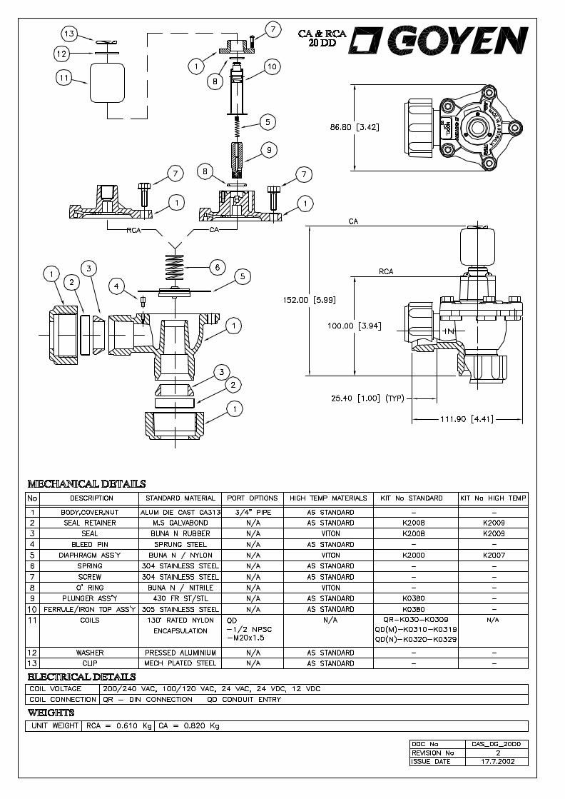
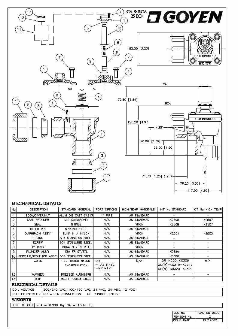


CAMCORP, INC. Phone: 913-831-0740 Fax: 913-831-9271
www.camcorpinc.com
Section 6- Troubleshooting
Troubleshooting the Dust Collector
Excessive Pressure Drop Across Filter Bags
The differential pressure gauge or manometer on your dust collector should read 6” w.g. or less. Higher readings and/or steadily increasing readings are an indication that the main airflow through the dust collector may be restricted and a potential process problem such as poor suction at duct pickup points may exist. In extreme cases (over 17” w.g.) filter bags will be damaged. Check the following:
Pressure Gauge Check the differential pressure gauge or manometer and the tubing leading to the dust collector for proper operation. Disconnect the lines at the gauge or manometer and clear with compressed air. Look for loose fittings, cracked, broken or pinched tubing. Make sure that the gauge is zeroed or that the manometer is level, zeroed and contains the correct fluid.
Compressed Air System Inspect the compressed air system as follows to make sure that all of the filter bags are being cleaned:
If none of the solenoid valves are operating check the timer using the “Troubleshooting the Timer” section.
Check the air pressure at the compressed air manifold. It should recover to 90-100 psig before each pulse. If not, check to make sure that the compressed air supply system is in good operating condition, correctly sized, and supply lines are not too small or restricted. Listen for the sound of compressed air flowing continuously through one or more diaphragm valves. This is an indication of a valve or valves “stuck” in the pulsing position. The usual causes for this condition are either a leak in the tubing between the solenoid and diaphragm valves or dirt in the solenoid and/or diaphragm valves.
Check to see that all solenoid valves are firing by holding a finger over each solenoid exhaust port as described in the “Start Up Checklist” section.
6-1
CAMCORP, INC. Phone: 913-831-0740 Fax: 913-831-9271
www.camcorpinc.com
Troubleshooting the Dust Collector (continued) Bags Loaded with Dust
This is a condition known as blinding. If the dust is dry see the next four paragraphs below. If the dust is wet see the paragraphs below on “Water Leaks” and “Condensation”.
Dust Not Discharging from the Hopper Check hopper for over-loading or bridging across the dust discharge. Correct by repairing dust discharge equipment, replacing with higher capacity equipment, installing hopper vibrators, etc. as required to keep the hopper empty.
Air Flow Too High If the main airflow is too high to allow dust to drop off of the filter bags, an excessive pressure drop across the dust collector will result and dust will build up in the system. In many cases this high pressure drop in turn leads to a reduction in the main air flow so that it is necessary to remove the dust accumulation from the filter bags (and the rest of the system) before measuring the main air flow volume.
Visually inspect the bags for heavy caking. If caking is evident see the note below and take the necessary action to clean the bags. Next, measure the main airflow with a pitot tube or equivalent device and compare with the original volume for which the unit was designed. If the flow is too high, cut back the main fan to prevent a recurrence of the problem.
Particle Size and Dust Load If possible, compare the dust particle size and loading with the original design specifications. Finer dust may cause a higher pressure drop. Do not hesitate to call CAMCORP as we have experience with many kinds of dust.
Bags Too Tight Bags that have shrunk on their cages may not flex sufficiently during the compressed air pulse to loosen caked dust. If the bags were cleaned or laundered pull a bag tight around its cage. You should be able to “gather” a small fold of material between your fingers.
Water Leaks Inspect the dust collector housing and ductwork for holes, cracks or loose gasketing where water could enter the collector.
6-2

CAMCORP, INC. Phone: 913-831-0740 Fax: 913-831-9271
www.camcorpinc.com
Troubleshooting the Dust Collector (continued)
Condensation If moisture has been condensing inside the collector check the dew point temperature of the incoming air stream. It may be necessary to insulate the collector and/or the ductwork leading to the collector to keep surface temperatures above the dew point and prevent condensation inside the dust collector.
NOTE: Collectors that have blinded bags can possibly be put into service by running the pulsing air system for 15 to 30 minutes with a 10 second “off time” and without the main fan or blower running. If the pressure drop is not lower when the main fan is started again remove the filter bags from the collector and replace. Make sure the timer “off time” has been reset to specifications prior to re-start. Information pertaining to filter bag cleaning may be obtained by calling your CAMCORP sales representative.
Extremely Low Pressure Drop
Differential Pressure Gauge Check the differential pressure gauge or manometer and the tubing leading to the dust collector.
Holes in Filter Bags or Bags Incorrectly Installed Inspect the filter bags for holes, rips, tears or excessive wear. Assure that the filter bags were installed correctly according to the “Bag & Cage Installation” section.
Ductwork and Dampers Inspect the ductwork to and from the dust collector for air leaks or blockage. Assure that any dampers in the system are correctly positioned to allow for proper air flow through the dust collector.
Leaks in the Housing Check the tube sheet (flat steel sheets from which the filter bags are suspended) and the dust collector housing for holes, cracks or loose gasketing that would permit air to bypass the dust collector or filter bags.
6-3
CAMCORP, INC. Phone: 913-831-0740 Fax: 913-831-9271
www.camcorpinc.com
Troubleshooting the Dust Collector (continued)
Continuous Flow of Dust in the Clean Air Exhaust (Primary Dusting)
Holes in the tube sheets Check the tube sheet for holes, cracks or loose bolts that would permit dusty air to bypass the filter bags.
Puff of dust in the clean air exhaust after each pulse (Secondary Dusting)
Compressed air manifold pressure too high Check compressed air manifold pressure gauge. If the pulsing air pressure is over 100 psig the filter bags may flex excessively and allow fine dust to pass through the bag material.
Worn filter bags Inspect the filter bags for wear. Thin worn bags may not stop fine dust when flexed by a compressed air pulse.
Residual dust If dust has migrated into the clean air plenum because of a dropped filter bag, torn filter bag or a hole in tube sheet, etc., the pulsing air may stir up the dust and allow it to escape into the clean air exhaust after each pulse. Residual dust may also be driven down inside the filter bags by the pulsing air. If the filter bags are filled with several inches of dust clean both the clean air plenum and the filter bags to avoid further problems.
Short Filter Bag Life
This is often a complicated problem to diagnose and we recommend calling the factory for advice. The following list may be helpful in performing some preliminary checks:
Temperature Operating Temperature above the recommended limit of the filter bag material.
6-4

CAMCORP, INC. Phone: 913-831-0740 Fax: 913-831-9271
www.camcorpinc.com
Troubleshooting the Dust Collector (continued)
Chemical attack Bag material degrades due to attack from certain chemicals in the dust or gasses in the air stream. High moisture High moisture content in the collector may cause certain filter bag material to shrink, degrade (more rapidly at elevated temperatures) or blind off.
Localized abrasion Abrasion of the filter bags where high velocity dusty air hits the filter bags. A dust impingement baffle may be required to be installed on the inlet of the dust collector.
Filter bag cages failure Corroded, rusted, or broken filter bag cages can cause excessive bag wear. Stainless steel or coated cages are available.
Troubleshooting the Timer
Check for mechanical damage. If the “Power On” indicator is not on, check for 120 VAC power input. The “hot” line connection must be connected to terminal “L1”, as this is the fused terminal.
Check for a blown fuse; if replacement is necessary, use only 2 AMP standard 3AG fuse (1-1/4” long). Do not use a slow-blow type fuse.
Check the wiring from the timer to the solenoids for open or short circuits.
After performing the steps above, if the timer is still not functioning properly (no output voltage, sequencing problems, etc.) please contact your CAMCORP representative.
6-5

CAMCORP, INC. Phone: 913-831-0740 Fax: 913-831-9271
www.camcorpinc.com
Troubleshooting the Compressed Air System Pulsing failure of all valves or the same numbered valve on each header
Pulse timer board inoperative Check pulse timer board for 120 VAC pulse between each numbered terminal on timer board and solenoid common terminal. Repair or replace timer if necessary.
Open or short circuit in wiring between pulse timer board and solenoids Check continuity with ohmmeter or suitable tester and repair as required.
Pulsing failure of valves at any location
Plastic plug in solenoid exhaust port Remove and discard plug.
Ruptured diaphragm Disassemble valve in question and inspect diaphragm(s). Replace with a repair kit if necessary.
Pinched or plugged tubing between solenoid and diaphragm valve. Inspect tubing and replace if necessary.
Continuous passage of compressed air through one of more blowpipes
¼” O.D. tubing or fittings disconnected, leaking or broken. Inspect and repair as required. Always use new ferrules in fittings when replacing copper tubing. Diaphragm valve air bleed hole or passage restricted Disassemble and inspect the diaphragm valve in question as follows:
• ¾” valves – check for plugged air bleed hole in diaphragm. • 1” valves – check for plugged air bleed passages in valve body and cover. • 1 ½” valves – check for plugged or restricted air bleed passages.
6-6

CAMCORP, INC. Phone: 913-831-0740 Fax: 913-831-9271
www.camcorpinc.com
Section 7 – Routine Maintenance
Inspection
Frequency will vary as widely as there are operating conditions. In general proceed as follows:
Daily – Check unit differential pressure.
Weekly – Check pulse timer board and solenoid valves for function. This usually is only listening to check uniform time in intervals between blasts.
Monthly – Lubricate fan, rotary valve and screw conveyor. Check seals on latter two for dust loss.
Quarterly – On Top Access Units, check for dust accumulation in clean air plenum.
Repairs
Filter bags – Generally replacement, although some applications can be laundered.
Solenoid Valves – Repair kits are available if a valve is stuck open or fails to operate.
Diaphragm Valves – Repair kits are available if a valve is stuck open or fails to operate due to a ruptured diaphragm.
Rotary Valves – Usually a matter of periodic seal and blade replacement. More detailed information is supplied with the valve.
Screw Conveyors – Periodic replacement of “V” belts and shaft seals. Inspect hanger bearings during filter bag change. Failure will be detected by the squeal.
Fans – “V” belt tension and replacement of bearings if running rough. Make sure rotor balance is maintained.
7-1
CAMCORP, INC. Phone: 913-831-0740 Fax: 913-831-9271
www.camcorpinc.com
Section 8 – Appendix Dust Collection Terms & Definitions Air-to-Cloth Ratio – Ratio of the volume of gas filtered (in ACFM) to the amount of filter media (in square feet). Bag Blinding – A condition where dust particles become embedded in the fabric over time and are not removed by the cleaning mechanism. This results in an increased pressure drop across the filter bag media. Bleed Through – Small particles of dust that are able to migrate through the filter bags. Bridging – A material blockage across an opening such as a hopper or between filter bags or cartridges. Can Velocity – The upward velocity of air through a cross section of the dust collector. Clean Air Plenum – The area of the dust collector where the air passes through after being filtered by the filter media. Diaphragm Valve – A compressed air valve that provides a volume of high-pressure air to clean the filter media. Differential Pressure – The variance in pressure between two measured points. On a dust collector this is generally measured on each side of the tube sheet to indicate the condition of the filter bags. This is typically measured in inches of water. Dirty Air Plenum – The area of the dust collector where the filter media hangs and the air has dust particulate in it. Dust Cake – The normal build up on the outside of the filter media. A dust cake is needed to provide the maximum filtering efficiency. Filter Media – An air permeable material that provides a means to separate the particulate from the air. This is usually a felt or woven bag or a pleated cartridge. Inches of Water – The standard unit of measurement for dust collector differential pressure. A typical notation is 2” w.c. ( water column) or 2” w.g. (water gauge).
8-1
CAMCORP, INC. Phone: 913-831-0740 Fax: 913-831-9271
www.camcorpinc.com
Magnehelic Gauge – A standard devise used to measure differential pressure. Pressure Drop – Another term for differential pressure or the drop in pressure between two measured points. Re-Entrainment – The re-depositing of dust on the filter media after it has been cleaned off. This can be caused by turbulence in the hopper (or dirty air plenum) or by excessive airflow through the dust collector. Solenoid Valve – In the case of a dust collector, a solenoid valve is used to open and close a diaphragm valve. It does this by venting compressed air from the backside of the diaphragm which allows the diaphragm to open. Smart Timer Board – A timer that senses the differential pressure and only cleans (pulses) the filter media when differential pressure is high (when the bags / cartridges are dirty). This provides for more economical use of compressed air. The Smart Timer also provides additional features not available on a standard timer. See Section 5 on Smart Timers for more details. Timer Board – An electrical device that provides the electrical signal to the solenoids to pulse the diaphragm valves. Tubesheet – The steel plate that supports the filter media (bags or cartridges). This plate separates the dirty air plenum from the clean air plenum.
8-2