installation, operation, maintenance -...
TRANSCRIPT

YLAA0070 - YLAA0175AIR-COOLED SCROLL CHILLERS
WITH MICROCHANNEL CONDENSER COILSSTYLE A (60 Hz)
70 - 175 TON246-613 KW
INSTALLATION, OPERATION, MAINTENANCE
AIR-COOLED LIQUID CHILLERSHERMETIC SCROLL
Replaces 150.72-nm1 (908) Form 150.72-nm1 (110)
R-410A
035-21911-000
Interim
GS560418.jpg
Products are produced at af ac i l i t y whose qua l i t y -management systems areISO9001 certified.
JOHnSOn COnTROLS2
FORm 150.72-nm1 (110)
This equipment is a relatively complicated apparatus. During installation, operation, maintenance or service, individuals may be exposed to certain components or conditions including, but not limited to: refrigerants, oils, materials under pressure, rotating components, and both high and low voltage. Each of these items has the potential, if misused or handled improperly, to cause bodily injury or death. It is the obligation and responsibility of operating/service personnel to identify and recognize these inherent hazards, protect themselves, and proceed safely in completing their tasks. Failure to comply with any of these requirements could result in serious damage to the equipment and the property in
IMPORTANT!READ BEFORE PROCEEDING!
GENERAL SAFETY GUIDELINES
which it is situated, as well as severe personal injury or death to themselves and people at the site.
This document is intended for use by owner-authorized operating/service personnel. It is expected that this individual possesses independent training that will enable them to perform their assigned tasks properly and safely. It is essential that, prior to performing any task on this equipment, this individual shall have read and understood this document and any referenced materials. This individual shall also be familiar with and comply with all applicable governmental standards and regulations pertaining to the task in question.
SAFETY SYMBOLSThe following symbols are used in this document to alert the reader to areas of potential hazard:
CAUTION identifies a hazard which could lead to damage to the machine, damage to other equipment and/or environmental pollution. Usually an instruction will be given, together with a brief explanation.
NOTE is used to highlight additional information which may be helpful to you.
DANGER indicates an imminently hazardous situation which, if not avoided, will result in death or serious injury.
WARNING indicates a potentially hazardous situation which, if not avoided, could result in death or seri-ous injury.
External wiring, unless specified as an optional connection in the manufacturer’s product line, is not to be connected inside the micro panel cabinet. Devices such as relays, switches, transducers and controls may not be installed inside the panel. no external wiring is al-lowed to be run through the micro panel. All wiring must be in accordance with Johnson Controls published specifications and must be performed only by qualified Johnson Controls personnel. Johnson Controls will not be responsible for damages/problems resulting from improper connections to the controls or application of improper control signals. Failure to follow this will void the manufacturer’s warranty and cause serious damage to property or injury to persons.

FORm 150.72-nm1 (110)
3JOHnSOn COnTROLS
In complying with Johnson Controls policy for continuous product improvement, the information contained in this document is subject to change without notice. While Johnson Controls makes no commitment to update or provide current information automatically to the manual owner, that information, if applicable, can be obtained by contacting the nearest Johnson Controls Engineered Systems Service office.
CHANGEABILITY OF THIS DOCUMENTIt is the responsibility of operating/service personnel to verify the applicability of these documents to the equipment in question. If there is any question in the mind of operating/service personnel as to the applicability of these documents, then prior to working on the equipment, they should verify with the owner whether the equipment has been modified and if current literature is available.

JOHnSOn COnTROLS4
FORm 150.72-nm1 (110)
THIS PAGE INTENTIONALLY LEFT BLANK

FORm 150.72-nm1 (110)
5JOHnSOn COnTROLS
TABLE OF CONTENTS
SECTION 1 – GENERAL CHILLER INFORMATION AND SAFETY ................................................................15INTRODUCTION .........................................................................................................................................15WARRANTY ................................................................................................................................................15SAFETY AND QUALITY..............................................................................................................................15
Standards for Safety and Quality .......................................................................................................15Responsibility for Safety ....................................................................................................................16
ABOUT THIS MANUAL...............................................................................................................................16MISUSE OF EQUIPMENT ...........................................................................................................................16
Suitability for Application ...................................................................................................................16Structural Support ...............................................................................................................................16Mechanical Strength ..........................................................................................................................16General Access ....................................................................................................................................16Pressure Systems ...............................................................................................................................17Electrical ...............................................................................................................................................17Rotating Parts ......................................................................................................................................17Sharp Edges .........................................................................................................................................17Refrigerants and Oils ..........................................................................................................................17High Temperature and Pressure Cleaning ........................................................................................17Emergency Shutdown .........................................................................................................................17
SECTION 2 – PRODUCT DESCRIPTION .........................................................................................................19INTRODUCTION .........................................................................................................................................19GENERAL SYSTEM DESCRIPTION ..........................................................................................................19
Compressors .......................................................................................................................................19Cooler (Evaporator) .............................................................................................................................19Condenser ............................................................................................................................................20Millennium Control Center ..................................................................................................................20
COMMUNICATIONS....................................................................................................................................21HIGH AMBIENT KIT ....................................................................................................................................21BUILDING AUTOMATION SYSTEM INTERFACE ......................................................................................21POWER PANEL ...........................................................................................................................................21ACCESSORIES AND OPTIONS .................................................................................................................22
Power Options .....................................................................................................................................22Control Options ...................................................................................................................................22Compressor, Piping, Evaporator Options .........................................................................................22Condenser and Cabinet Options ........................................................................................................23
UNIT COMPONENTS .................................................................................................................................25CONTROL / POWER PANEL COMPONENTS ..........................................................................................27PRODUCT IDENTIFICATION NUMBER (PIN) ............................................................................................29BASIC UNIT NOMENCLATURE .................................................................................................................29PROCESS AND INSTRUMENTATION DIAGRAM .....................................................................................35

JOHnSOn COnTROLS6
FORm 150.72-nm1 (110)
TABLE OF CONTENTS (CONT’D)
SECTION 3 – HANDLING AND STORAGE ......................................................................................................37DELIVERY AND STORAGE ........................................................................................................................37INSPECTION ...............................................................................................................................................37MOVING THE CHILLER ..............................................................................................................................37
Lifting Weights .....................................................................................................................................37Rigging Instructions ............................................................................................................................38
SECTION 4 – INSTALLATION ...........................................................................................................................39INSTALLATION CHECKLIST ......................................................................................................................39HANDLING ..................................................................................................................................................39INSPECTION ...............................................................................................................................................39LOCATION AND CLEARANCES ................................................................................................................39
Foundation ...........................................................................................................................................39Ground Level Locations .....................................................................................................................40Rooftop Locations ...............................................................................................................................40Noise Sensitive Locations ..................................................................................................................40
SPRING ISOLATORS (OPTIONAL) ............................................................................................................40COMPRESSOR MOUNTING ......................................................................................................................40REMOTE COOLER OPTION ......................................................................................................................40CHILLED LIQUID PIPING ...........................................................................................................................40PIPEWORK ARRANGEMENT ....................................................................................................................41DUCT WORK CONNECTION ....................................................................................................................42
General Requirements .......................................................................................................................42WIRING ........................................................................................................................................................42
Evaporator Pump Start Contacts .......................................................................................................42System Run Contacts .........................................................................................................................42Alarm Status Contacts ........................................................................................................................43Remote Start/Stop Contacts ...............................................................................................................43Remote Emergency Cutoff .................................................................................................................43Remote Temp Reset Input ..................................................................................................................43Load Limit Input ...................................................................................................................................43Flow Switch Input ................................................................................................................................43
COMPRESSOR HEATERS .........................................................................................................................43RELIEF VALVES .........................................................................................................................................43HIGH PRESSURE CUTOUT .......................................................................................................................43SINGLE-POINT SUPPLY CONNECTION – TERMINAL BLOCK, NON-FUSED DISCONNECT SWITCH OR CIRCUIT BREAKER ..............................................................................................................44USER CONTROL WIRING INPUTS ............................................................................................................45USER CONTROL WIRING OUTPUTS ........................................................................................................46

FORm 150.72-nm1 (110)
7JOHnSOn COnTROLS
SECTION 5 – TECHNICAL DATA .....................................................................................................................47OPERATIONAL LIMITATIONS (ENGLISH) ................................................................................................47
Temperatures and Flows ....................................................................................................................47Voltage Limitations ..............................................................................................................................47
HEAT EXCHANGER FLOW, GPM ..............................................................................................................48Ethylene & Propylene Glycol Correction Factors ............................................................................48
PHYSICAL DATA (ENGLISH) .....................................................................................................................50ELECTRICAL DATA ....................................................................................................................................52ELECTRICAL NOTES .................................................................................................................................53ELECTRICAL DATA W/O PUMPS ..............................................................................................................54
Wiring Lugs ..........................................................................................................................................58ELECTRICAL DATA W/ PUMPS .................................................................................................................60ELECTRICAL NOTES AND LEGEND ........................................................................................................68WIRING DIAGRAMS ...................................................................................................................................72
Elementary Wiring Diagrams ..............................................................................................................72Connection Diagrams .........................................................................................................................80
DIMENSIONS (ENGLISH) ...........................................................................................................................96TECHNICAL DATA – CLEARANCES .......................................................................................................101WEIGHT DISTRIBUTION AND ISOLATOR MOUNTING POSITIONS .....................................................102
General ...............................................................................................................................................102Sample Isolator Location Drawing ...................................................................................................102Isolator Locations ..............................................................................................................................103
ISOLATOR INFORMATION (For units shipped on or after June 15, 2008) ..........................................106One Inch Deflection Spring Isolator Cross-reference ....................................................................106One Inch Deflection Spring Isolators Installation Instructions .....................................................107Seismic Isolator Cross-reference ....................................................................................................108SEISMIC ISOLATOR INSTALLATION AND ADJUSTMENT..............................................................109Duralene Isolator Cross-reference ...................................................................................................110Installation of Durulene Vibration Isolators .................................................................................... 111
ISOLATOR INFORMATION (For units shipped before June 15, 2008) .....................................................112SLRS Seismic Isolator Specifications .............................................................................................112SLRS Seismic Isolator Installation and Adjustment ......................................................................113One Inch Deflection Spring Isolator Cross-reference ....................................................................114Installation of 1” Deflection Mounts ................................................................................................115Neoprene Isolator Cross-reference .................................................................................................116Two Inch Deflection, Seismic Spring Isolator Cross-reference - SLRS .......................................117SLRS Seismic Isolator Installation and Adjustment ......................................................................118
TABLE OF CONTENTS (CONT’D)

JOHnSOn COnTROLS8
FORm 150.72-nm1 (110)
SECTION 6 – COMMISSIONING .....................................................................................................................119PREPARATION – POWER OFF ................................................................................................................119
Inspection ..........................................................................................................................................119Refrigerant Charge ............................................................................................................................119Service and Oil Line Valves ..............................................................................................................119Compressor Oil ..................................................................................................................................119Fans ...................................................................................................................................................119Isolation / Protection .........................................................................................................................119Control Panel .....................................................................................................................................119Power Connections ...........................................................................................................................119Grounding ..........................................................................................................................................119Supply Voltage ...................................................................................................................................119
PREPARATION – POWER ON .................................................................................................................120Switch Settings ..................................................................................................................................120Compressor Heaters .........................................................................................................................120Water System .....................................................................................................................................120Flow Switch ........................................................................................................................................120Temperature Sensor(s) .....................................................................................................................120
EQUIPMENT PRE-STARTUP AND STARTUP CHECKLIST ...................................................................121Pre-Startup .........................................................................................................................................121Startup ................................................................................................................................................121
SETPOINTS ENTRY LIST .........................................................................................................................122CHECKING SUPERHEAT AND SUBCOOLING .......................................................................................123LEAK CHECKING .....................................................................................................................................123UNIT OPERATING SEQUENCE ...............................................................................................................124
SECTION 7 – UNIT CONTROLS .....................................................................................................................125INTRODUCTION .......................................................................................................................................125
IPU II and I/O Boards .........................................................................................................................125Unit Switch .........................................................................................................................................126Display ................................................................................................................................................126Keypad ................................................................................................................................................126Battery Back-up .................................................................................................................................126Transformer .......................................................................................................................................126Programming # of Compressors ......................................................................................................126
STATUS KEY ............................................................................................................................................127Unit Status ..........................................................................................................................................127General Status Messages .................................................................................................................127Fault Safety Status Messages ..........................................................................................................129System Safeties .................................................................................................................................129Unit Safeties .......................................................................................................................................131Unit Warning ......................................................................................................................................131Status Key Messages ........................................................................................................................132
TABLE OF CONTENTS (CONT’D)
FORm 150.72-nm1 (110)
9JOHnSOn COnTROLS
DISPLAY/PRINT KEYS .............................................................................................................................133Oper Data Key ....................................................................................................................................133Oper Data Quick Reference List .......................................................................................................136Print Key .............................................................................................................................................137Operating Data Printout ....................................................................................................................137History Printout .................................................................................................................................138History Displays ................................................................................................................................138Software Version ...............................................................................................................................140
ENTRY KEYS ............................................................................................................................................141Up and Down Arrow Keys .................................................................................................................141Enter/Adv Key ....................................................................................................................................141
SETPOINTS KEYS ....................................................................................................................................142Cooling Setpoints ..............................................................................................................................142Leaving Chilled Liquid Control ........................................................................................................142Return Chilled Liquid Control ..........................................................................................................143Remote Setpoint Control ..................................................................................................................143Schedule/Advance Day Key .............................................................................................................143
PROGRAM KEY ........................................................................................................................................145PROGRAM KEY LIMITS AND DEFAULT .................................................................................................147SETPOINTS QUICK REFERENCE LIST ..................................................................................................148UNIT KEYS ...............................................................................................................................................149
Options Key .......................................................................................................................................149CLOCK ......................................................................................................................................................153UNIT KEYS OPTIONS PROGRAMMING QUICK REFERENCE LIST .....................................................154
SECTION 8 – UNIT OPERATION ....................................................................................................................155CAPACITY CONTROL ..............................................................................................................................155SUCTION PRESSURE LIMIT CONTROLS ..............................................................................................155DISCHARGE PRESSURE LIMIT CONTROLS .........................................................................................155LEAVING CHILLED LIQUID CONTROL ...................................................................................................155LEAVING CHILLED LIQUID CONTROLOVERRIDE TO REDUCE CYCLING .........................................156LEAVING CHILLED LIQUID SYSTEM LEAD/LAG AND COMPRESSOR SEQUENCING .....................156RETURN CHILLED LIQUID CONTROL ....................................................................................................157RETURN CHILLLED LIQUID SYSTEM LEAD/LAG AND COMPRESSOR SEQUENCING ....................158ANTI-RECYCLE TIMER ............................................................................................................................159ANTI-COINCIDENCE TIMER ....................................................................................................................159EVAPORATOR PUMP CONTROL AND YORK HYDRO KIT PUMP CONTROL .....................................159EVAPORATOR HEATER CONTROL ........................................................................................................159PUMPDOWN CONTROL...........................................................................................................................159STANDARD CONDENSER FAN CONTROL ............................................................................................159LOAD LIMITING ........................................................................................................................................163COMPRESSOR RUN STATUS .................................................................................................................163ALARM STATUS .......................................................................................................................................163BAS/EMS TEMPERATURE RESET USINGA VOLTAGE OR CURRENT SIGNAL .................................164
TABLE OF CONTENTS (CONT’D)

JOHnSOn COnTROLS10
FORm 150.72-nm1 (110)
SECTION 9 – SERVICE AND TROUBLESHOOTING .....................................................................................165CLEARING HISTORY BUFFERS..............................................................................................................165SERVICE MODE........................................................................................................................................165SERVICE MODE – OUTPUTS ..................................................................................................................165SERVICE MODE – CHILLER CONFIGURATION .....................................................................................166SERVICE MODE – ANALOG AND DIGITAL INPUTS ..............................................................................166CONTROL INPUTS/OUTPUTS .................................................................................................................167MICROBOARD LAYOUT ..........................................................................................................................168CHECKING INPUTS AND OUTPUTS .......................................................................................................169
Digital Inputs ......................................................................................................................................169Analog Inputs – Temperature ...........................................................................................................169Outside Air Sensor ............................................................................................................................169Liquid & Refrigerant Sensor Test Points ........................................................................................170Analog Inputs – Pressure .................................................................................................................171Digital Outputs ...................................................................................................................................172
OPTIONAL PRINTER INSTALLATION .....................................................................................................173Parts ....................................................................................................................................................173Assembly and Wiring ........................................................................................................................173Obtaining a Printout ..........................................................................................................................173
TROUBLESHOOTING ..............................................................................................................................174
SECTION 10 – MAINTENANCE ......................................................................................................................177IMPORTANT ..............................................................................................................................................177COMPRESSORS .......................................................................................................................................177
Oil Level Check ..................................................................................................................................177Oil Analysis ........................................................................................................................................177
CONDENSER FAN MOTORS ...................................................................................................................177CONDENSER COILS ................................................................................................................................177OPERATING PARAMETERS ....................................................................................................................177ON-BOARD BATTERY BACK-UP ............................................................................................................177EVAPORATOR HEATER ...........................................................................................................................177OVERALL UNIT INSPECTION..................................................................................................................177BACNET, MODBUS AND YORKTALK 2 COMMUNICATIONS ................................................................178
BACnet and Modbus Communications ...........................................................................................181Communications Data Map Notes ...................................................................................................181Yorktalk 2 Communications .............................................................................................................185
TEMPERATURE CONVERSION CHART .................................................................................................189R410A PRESSURE TEMPERATURE CHART .........................................................................................190
TABLE OF CONTENTS (CONT’D)
FORm 150.72-nm1 (110)
11JOHnSOn COnTROLS
LIST OF FIGURES
FIG. 1 – UNIT COMPONENTS FRONT ....................................................................................................25FIG. 2 – UNIT COMPONENTS SIDE ........................................................................................................26FIG. 3 – POWER PANEL COMPONENTS ................................................................................................27FIG. 4 – POWER PANEL / CONTROL COMPONENTS ...........................................................................28FIG. 5 – REFRIGERANT FLOW DIAGRAM .............................................................................................34FIG. 6 – PROCESS AND INSTRUMENTATION DIAGRAM .....................................................................35FIG. 7 – UNIT RIGGING/LIFTING ............................................................................................................38FIG. 8 – CHILLED LIQUID SYSTEM ........................................................................................................41FIG. 9 – SINGLE-POINT SUPPLY CONNECTION – TERMINAL BLOCK, NON-FUSED DISCONNECT SWITCH OR CIRCUIT BREAKER .....................................................................44FIG. 10 – CONTROL WIRING INPUTS .......................................................................................................45FIG. 11 – CONTROL WIRING OUTPUTS ...................................................................................................46FIG. 12 – ELEMENTARY WIRING DIAGRAM, SHT 1 ................................................................................72FIG. 13 – ELEMENTARY WIRING DIAGRAM, SHT 2 ................................................................................74FIG. 14 – ELEMENTARY WIRING DIAGRAM, SHT 3 ................................................................................76FIG. 15 – ELEMENTARY WIRING DIAGRAM, SHT 4 ................................................................................78FIG. 16 – CONNECTION DIAGRAM, SHT 1 ..............................................................................................80FIG. 17 – CONNECTION DIAGRAM, SHT 2 ..............................................................................................82FIG. 18 – CONNECTION DIAGRAM, SHT 3 ..............................................................................................84FIG. 19 – CONNECTION DIAGRAM, SHT 6 ..............................................................................................86FIG. 20 – CONNECTION DIAGRAM, SHT 7 ..............................................................................................88FIG. 21 – DUAL PUMP WIRING .................................................................................................................90FIG. 22 – WIRING ........................................................................................................................................92FIG. 23 – WIRING DIAGRAM, SINGLE POINT WIRING OPTIONS ..........................................................94FIG. 24 – LAYOUT - POWER BLOCKS AND TRANSFORMERS ..............................................................95FIG. 25 – UNIT CLEARANCES – ALL MODELS .....................................................................................101FIG. 26 – LEAVING WATER TEMPERATURECONTROL EXAMPLE .....................................................155FIG. 27 – SETPOINT ADJUST ..................................................................................................................156FIG. 28 – CONDENSER FAN LOCATIONSWIRING DIAGRAMS ............................................................160FIG. 29 – MICROBOARD LAYOUT ..........................................................................................................168FIG. 30 – I/O BOARD RELAY CONTACT ARCHITECTURE ....................................................................172FIG. 31 – PRINTER TO MICROBOARD ELECTRICAL CONNECTIONS ................................................173FIG. 32 - MICRO PANEL CONNECTIONS ...............................................................................................179

JOHnSOn COnTROLS12
FORm 150.72-nm1 (110)
THIS PAGE INTENTIONALLY LEFT BLANK
FORm 150.72-nm1 (110)
13JOHnSOn COnTROLS
LIST OF TABLESTABLE 1 – TEMPERATURES AND FLOWS ............................................................................................47TABLE 2 – VOLTAGE LIMITATIONS ........................................................................................................47TABLE 3 – ETHYLENE AND PROPYLENE GLYCOL CORRECTION FACTORS ..................................48TABLE 4 – PHYSICAL DATA (ENGLISH) ................................................................................................50TABLE 5 – MICRO PANEL POWER SUPPLY ..........................................................................................52TABLE 6 – VOLTAGE RANGE .................................................................................................................52TABLE 7 – SETPOINTS ENTRY LIST ....................................................................................................122TABLE 8 – STATUS KEY MESSAGES QUICK REFERENCE LIST ......................................................132TABLE 9 – OPERATION DATA ...............................................................................................................136
TABLE 10 – COOLING SETPOINTS, PROGRAMMABLE LIMITS AND DEFAULTS .............................144TABLE 11 – PROGRAM KEY LIMITS AND DEFAULT .............................................................................147TABLE 12 – SETPOINTS QUICK REFERENCE LIST .............................................................................148TABLE 13 – UNIT KEYS OPTIONS PROGRAMMING QUICK REFERENCE LIST ................................154TABLE 14 – SAMPLE COMPRESSOR STAGING FOR RETURN WATER CONTROL ..........................157TABLE 15 – RETURN CHILLED LIQUID CONTROL FOR 4 COMPRESSORS (6 STEPS) ....................158TABLE 16 – RETURN CHILLED LIQUID CONTROL FOR 4 COMPRESSORS (6 STEPS) ....................158TABLE 17 – YLAA STANDARD CONDENSER FAN CONTROL USING DISCHARGE PRESSURE ONLY (2, 3, OR 4 FANS PER SYSTEM) .........................................................161TABLE 18 – YLAA STANDARD CONDENSER FAN CONTROL USING DISCHARGE PRESSURE ONLY (5 OR 6 FANS PER SYSTEM) ..............................................................162TABLE 19 – COMPRESSOR OPERATION – LOAD LIMITING ...............................................................163TABLE 20 – I/O DIGITAL INPUTS ............................................................................................................167TABLE 21 – I/O DIGITAL OUTPUTS ........................................................................................................167TABLE 22 – I/O ANALOG INPUTS ...........................................................................................................167TABLE 23 – I/O ANALOG OUTPUTS .......................................................................................................167TABLE 24 – OUTDOOR AIR SENSOR .....................................................................................................169TABLE 25 – ENTERING/LEAVING CHILLED LIQUID TEMP. SENSOR, TEMPERATURE/VOLTAGE CORRELATION .......................................................................170TABLE 26 – PRESSURE TRANSDUCERS ..............................................................................................171TABLE 27 – TROUBLESHOOTING ..........................................................................................................174TABLE 28 – MINIMUM, MAXIMUM AND DEFAULT VALUES .................................................................179TABLE 29 – VALUES REQUIRED FOR BAS COMMUNICATION ...........................................................180TABLE 30 – REAL TIME ERROR NUMBERS ..........................................................................................180TABLE 31 - BACNET AND MODBUS COMMUNICATIONS DATA MAP .................................................182TABLE 32 - YORKTALK 2 COMMUNICATIONS DATA MAP ...................................................................186

JOHnSOn COnTROLS14
FORm 150.72-nm1 (110)
THIS PAGE INTENTIONALLY LEFT BLANK

FORm 150.72-nm1 (110)
15JOHnSOn COnTROLS
1
SECTION 1 – GENERAL CHILLER INFORMATION AND SAFETYINTRODUCTION
YORK YLAA0070 - 0175 (70 -175 ton, 246 - 613kW) chillers are manufactured to the highest design and construction standards to ensure high performance, reliability and adaptability to all types of air conditioning installations.
The unit is intended for cooling water or glycol solutions and is not suitable for purposes other than those specified in this manual.
This manual contains all the information required for correct installation and commissioning of the unit, together with operating and maintenance instructions. The manuals should be read thoroughly before attempting to operate or service the unit.
All procedures detailed in the manuals, including installation, commissioning and maintenance tasks must only be performed by suitably trained and qualified personnel.
The manufacturer will not be liable for any injury or damage caused by incorrect installation, commissioning, operation or maintenance resulting from a failure to follow the procedures and instructions detailed in the manuals.
WARRANTY
Johnson Controls warrants all equipment and materials against defects in workmanship and materials for a period of eighteen months from date of shipment, or 12 months from date of shipment, whichever occurs first, unless labor or extended warranty has been purchased as part of the contract.
The warranty is limited to parts only replacement and shipping of any faulty part, or sub-assembly, which has failed due to poor quality or manufacturing errors. All claims must be supported by evidence that the failure has occurred within the warranty period, and that the unit has been operated within the designed parameters specified.
All warranty claims must specify the unit model, serial number, order number and run hours/starts. Model and serial number information is printed on the unit identification plate.
The unit warranty will be void if any modification to the unit is carried out without prior written approval from Johnson Controls.
For warranty purposes, the following conditions must be satisfied:
• The initial start of the unit must be carried out by trained personnel from an Authorized Johnson Controls Service Center (see Commissioning Page 119).
• Only genuine YORK approved spare parts, oils, coolants, and refrigerants must be used.
• All the scheduled maintenance operations detailed in this manual must be performed at the specified times by suitably trained and qualified personnel (see Maintenance Section, Page 177).
• Failure to satisfy any of these conditions will automatically void the warranty (see Warranty Policy).
SAFETY AND QUALITY
Standards for Safety and QualityYLAA chillers are designed and built within an ISO 9002 accredited design and manufacturing organization. The chillers comply with the applicable sections of the following Standards and Codes:
• ANSI/ASHRAE Standard 15- Safety Code for Mechanical Refrigeration.
• ANSI/NFPA Standard 70- National Electrical Code (N.E.C.).
• ASME Boiler and Pressure Vessel Code- Section VIII Division 1.
• ARI Standard 550/590 - Positive Displacement Compressors and Air Cooled Rotary Screw Water Chilling Packages.
• ASHRAE 90.1- Energy Efficiency compliance.
• Conform to Intertek Testing Services, formerly ETL, for construction of chillers and provide ETL/cETL listing label.
• Manufactured in facility registered to ISO 9002.
• OSHA – Occupational Safety and Health Act.

JOHnSOn COnTROLS16
FORm 150.72-nm1 (110)General Chiller Introduction & Safety
In addition, the chillers conform to Underwriters Laboratories (U.L.) for construction of chillers and provide U.L./cU.L. Listing Label.
Responsibility for SafetyEvery care has been taken in the design and manufacture of the unit to ensure compliance with the safety requirements listed above. However, the individual operating or working on any machinery is primarily responsible for:
• Personal safety, safety of other personnel, and the machinery.
• Correct utilization of the machinery in accordance with the procedures detailed in the manuals.
ABOUT THIS MANUAL
The following terms are used in this document to alert the reader to areas of potential hazard.
A WARnInG is given in this document to identify a hazard, which could lead to personal injury. Usually an instruction will be given, together with a brief explanation and the possible result of ignoring the instruction.
A CAUtIon identifies a hazard which could lead to damage to the machine, damage to other equipment and/or environmental pollution. Usually an instruction will be given, together with a brief explanation and the possible result of ignoring the instruction.
A NOTE is used to highlight additional information, which may be helpful to you but where there are no special safety implications.
The contents of this manual include suggested best working practices and procedures. These are issued for guidance only, and they do not take precedence over the above stated individual responsibility and/or local safety regulations.
This manual and any other document supplied with the unit are the property of Johnson Controls which reserves all rights. They may not be reproduced, in whole or in part, without prior written authorization from an authorized Johnson Controls representative.
MISUSE OF EQUIPMENT
Suitability for ApplicationThe unit is intended for cooling water or glycol solutions and is not suitable for purposes other than those specified in these instructions. Any use of the equipment other than its intended use, or operation of the equipment contrary to the relevant procedures may result in injury to the operator, or damage to the equipment.
The unit must not be operated outside the design parameters specified in this manual.
Structural SupportStructural support of the unit must be provided as indicated in these instructions. Failure to provide proper support may result in injury to the operator, or damage to the equipment and/or building.
Mechanical Strength The unit is not designed to withstand loads or stresses from adjacent equipment, pipework or structures. Additional components must not be mounted on the unit. Any such extraneous loads may cause structural failure and may result in injury to the operator, or damage to the equipment.
General AccessThere are a number of areas and features, which may be a hazard and potentially cause injury when working on the unit unless suitable safety precautions are taken. It is important to ensure access to the unit is restricted to suitably qualified persons who are familiar with the potential hazards and precautions necessary for safe operation and maintenance of equipment containing high temperatures, pressures and voltages.

FORm 150.72-nm1 (110)
17JOHnSOn COnTROLS
1
Pressure SystemsThe unit contains refrigerant vapor and liquid under pressure, release of which can be a danger and cause injury. The user should ensure that care is taken during installation, operation and maintenance to avoid damage to the pressure system. No attempt should be made to gain access to the component parts of the pressure system other than by suitably trained and qualified personnel.
ElectricalThe unit must be grounded. No installation or maintenance work should be attempted on the electrical equipment without first switching power OFF, isolating and locking-off the power supply. Servicing and maintenance on live equipment must only be performed by suitably trained and qualified personnel. No attempt should be made to gain access to the control panel or electrical enclosures during normal operation of the unit.
Rotating PartsFan guards must be fitted at all times and not removed unless the power supply has been isolated. If ductwork is to be fitted, requiring the wire fan guards to be removed, alternative safety measures must be taken to protect against the risk of injury from rotating fans.
Sharp EdgesThe fins on the air-cooled condenser coils have sharp metal edges. Reasonable care should be taken when working in contact with the coils to avoid the risk of minor abrasions and lacerations. The use of gloves is recommended.
Frame rails, brakes, and other components may also have sharp edges. Reasonable care should be taken when working in contact with any components to avoid risk of minor abrasions and lacerations.
Refrigerants and OilsRefrigerants and oils used in the unit are generally nontoxic, non-flammable and non-corrosive, and pose no special safety hazards. Use of gloves and safety glasses is, however, recommended when working on the unit. The build up of refrigerant vapor, from a leak for example, does pose a risk of asphyxiation in confined or enclosed spaces and attention should be given to good ventilation.
High Temperature and Pressure CleaningHigh temperature and pressure cleaning methods (e.g. steam cleaning) should not be used on any part of the pressure system as this may cause operation of the pressure relief device(s). Detergents and solvents, which may cause corrosion, should also be avoided.
Emergency ShutdownIn case of emergency, the control panel is fitted with a Unit Switch to stop the unit in an emergency. When operated, it removes the low voltage 120 VAC electrical supply from the inverter system, thus shutting down the unit.

JOHnSOn COnTROLS18
FORm 150.72-nm1 (110)
THIS PAGE INTENTIONALLY LEFT BLANK
FORm 150.72-nm1 (110)
19JOHnSOn COnTROLS
2
SECTION 2 – PRODUCT DESCRIPTION
INTRODUCTION
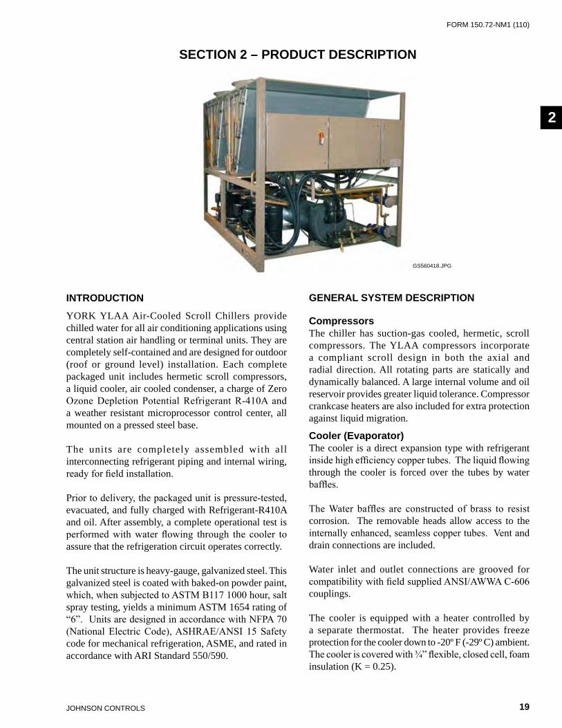
YORK YLAA Air-Cooled Scroll Chillers provide chilled water for all air conditioning applications using central station air handling or terminal units. They are completely self-contained and are designed for outdoor (roof or ground level) installation. Each complete packaged unit includes hermetic scroll compressors, a liquid cooler, air cooled condenser, a charge of Zero Ozone Depletion Potential Refrigerant R-410A and a weather resistant microprocessor control center, all mounted on a pressed steel base.
The units are completely assembled with all interconnecting refrigerant piping and internal wiring, ready for field installation.
Prior to delivery, the packaged unit is pressure-tested, evacuated, and fully charged with Refrigerant-R410A and oil. After assembly, a complete operational test is performed with water flowing through the cooler to assure that the refrigeration circuit operates correctly.
The unit structure is heavy-gauge, galvanized steel. This galvanized steel is coated with baked-on powder paint, which, when subjected to ASTM B117 1000 hour, salt spray testing, yields a minimum ASTM 1654 rating of “6”. Units are designed in accordance with NFPA 70 (National Electric Code), ASHRAE/ANSI 15 Safety code for mechanical refrigeration, ASME, and rated in accordance with ARI Standard 550/590.
GENERAL SYSTEM DESCRIPTION
CompressorsThe chiller has suction-gas cooled, hermetic, scroll compressors. The YLAA compressors incorporate a compliant scroll design in both the axial and radial direction. All rotating parts are statically and dynamically balanced. A large internal volume and oil reservoir provides greater liquid tolerance. Compressor crankcase heaters are also included for extra protection against liquid migration.
Cooler (Evaporator)The cooler is a direct expansion type with refrigerant inside high efficiency copper tubes. The liquid flowing through the cooler is forced over the tubes by water baffles.
The Water baffles are constructed of brass to resist corrosion. The removable heads allow access to the internally enhanced, seamless copper tubes. Vent and drain connections are included.
Water inlet and outlet connections are grooved for compatibility with field supplied ANSI/AWWA C-606 couplings.
The cooler is equipped with a heater controlled by a separate thermostat. The heater provides freeze protection for the cooler down to -20º F (-29º C) ambient. The cooler is covered with ¾” flexible, closed cell, foam insulation (K = 0.25).
GS560418.JPG
JOHnSOn COnTROLS20
FORm 150.72-nm1 (110)Product Description
The evaporator is constructed, tested and stamped in accordance with applicable sections of ASME pressure vessel code for minimum 450 PSIG (3103 kPa) refrigerant side design working pressure and 150 PSIG (1034 kPa) water side design working pressure
A strainer with a mesh size between .5 and 1.5 mm (40 mesh) is recommended upstream of the heat exchanger to prevent clogging from water system debris.
Condenser
Coils
Condenser coils are Microchannel type and made of a single material to avoid galvanic corrosion due to dissimilar metals. Coils and headers are brazed as one piece. Integral sub cooling is included. The design working pressure of the coil is 650 PSIG (45 bar).
Low Sound Fans
The condenser fans are composed of corrosion resistant aluminum hub and glass-fiber reinforced polypropylene composite blades molded into a low noise airfoil section. They are designed for maximum efficiency and are statically and dynamically balanced for vibration free operation. They are directly driven by independent motors, and positioned for vertical air discharge. The fan guards are constructed of heavy gauge, rust resistant, coated steel. All blades are statically and dynamically balanced for vibration free operation.
Motors
The fan motors are Totally Enclosed Air-Over, squirrel cage type, current protected. They feature ball bearings that are double sealed and permanently lubricated.
Ambient Kit (High)Required if units are to operate when the ambient temperature is above 115°F (46°C). Includes discharge pressure transducers.
Millennium Control CenterAll controls are contained in a NEMA 3R/12 cabinet with hinged outer door and includes Liquid Crystal Display with Light Emitting Diode backlighting for outdoor viewing:
• Two display lines • Twenty characters per line
Display/Print
Color coded 12-button non-tactile keypad with sections for display and print of typical information:
• Chilled liquid temperatures • Ambient temperature • System pressures (each circuit) • Operating hours and starts (each compressor) • Print calls up to the liquid crystal display • Operating data for the systems • History of fault shutdown data for up to the last
six fault shutdown conditions. • An RS-232 port, in conjunction with this press-to-
print button, is provided to permit the capability of hard copy print-outs via a separate printer (by others).
Entry
This section is used to enter setpoints or modify system values.
Setpoints
Updating can be performed to: • Chilled liquid temperature setpoint and range • Remote reset temperature range • Set daily schedule/holiday for start/stop • Manual override for servicing • Low and high ambient cutouts • Number of compressors • Low liquid temperature cutout • Low suction pressure cutout • High discharge pressure cutout • Anti-recycle timer (compressor start cycle
time) • Anti-coincident timer (delay compressor starts)
Unit
This section is used to: • Set time • Set unit options
FORm 150.72-nm1 (110)
21JOHnSOn COnTROLS
2
Unit On/Off
The microprocessor control center is capable of displaying the following:
• Return and leaving liquid temperature • Low leaving liquid temperature cutout setting • Low ambient temperature cutout setting • Outdoor air temperature • English or Metric data • Suction pressure cutout setting • Each system suction pressure • Discharge pressure (optional) • Liquid Temperature Reset via a Johnson Controls
ISN DDC or Building Automation System (by others) via a 4 to 20 milliamp or 0 to10 VDC input.
• Anti-recycle timer status for each system • Anti-coincident system start timer condition • Compressor run status • No cooling load condition • Day, date and time • Daily start/stop times • Holiday status • Automatic or manual system lead/lag control • Lead system definition • Compressor starts and operating hours (each compressor) • Status of hot gas valves, evaporator heater and fan operation • Run permissive status • Number of compressors running • Liquid solenoid valve status • Load and unload timer status • Water pump status
Provisions are included for: pumpdown at shutdown; optional remote chilled water temperature reset and two steps of demand load limiting from an external building automation system. Unit alarm contacts are standard.
* Intensity of Protection European Standard** International Electrotechnical Commission
The operating program is stored in non-volatile memory battery backed RAM to eliminate chiller failure due to AC powered failure/battery discharge. Programmed setpoints are retained in lithium battery-backed RTC memory for 5 years minimum.
COMMUNICATIONS
• Native communication capability for BACnet (MS/TP) and Modbus
• Optional communication available for N2 and LON via eLink option
HIGH AMBIENT KIT
Allows units to operate when the ambient temperature is above 115°F (46°C). Includes sun shield panels and discharge pressure transducers.
BUILDING AUTOMATION SYSTEM INTERFACE
The Microprocessor Board can accept a 4 to 20 milliamp, 0 to10VDC input to reset the leaving chiller liquid temperature from a Building Automation System.
• The standard unit capabilities include remote start-stop, remote water temperature reset via a PWM 4 to 20 milliamp or 0 to 10VDC input sig-nal or up to two stages of demand (load) limiting depending on model.
• The standard control panel can be directly con-nected to a Johnson Controls Building Automated System.
POWER PANEL
Each panel contains: • Compressor power terminals • Compressor motor starting contactors per
l.E.C.** • Control power terminals to accept incoming for
115-1-60 control power • Fan contactors and overload current protection
The power wiring is routed through liquid-tight conduit to the compressors and fans.
JOHnSOn COnTROLS22
FORm 150.72-nm1 (110)Product Description
ACCESSORIES AND OPTIONS
Power Options
Compressor Power Connections
Single-point terminal block connection(s) are provided as standard. The following power connections are available as options. (See electrical data for specific voltage and options availability.) (Factory-mounted)
Single-Point Supply Terminal Block
Includes enclosure, terminal-block and interconnecting wiring to the compressors. Separate external protection must be supplied, by others, in the incoming compressor-power wiring. (Do not include this option if either the Single-Point Non-Fused Disconnect Switch or Single-Point Circuit Breaker options have been included.)
Single-Point Non-Fused Disconnect Switch Or Multiple-Point Non-Fused Disconnect Swithches
Unit-mounted disconnect switch (es) with external, lockable handle (in compliance with Article 440-14 of N.E.C.), can be supplied to isolate the unit power voltage for servicing. Separate external fusing must be supplied, by others in the power wiring, which must comply with the National Electrical Code and/or local codes.
Single-Point Non-Fused Disconnect Switch With Individual System Breakers
Includes unit-mounted disconnect switch with external, lockable handles (in compliance with Article 440-14 of N.E.C.) to isolate unit power voltage for servicing. Factory interconnecting wiring is provided from the disconnect switch to factory supplied system circuit breakers.
Single-Point Circuit Breaker
A unit mounted circuit breaker with external, lockable handle (in compliance with N.E.C. Article 440-14); can be supplied to isolate the power voltage for servicing. (This option includes the Single-Point Power connection.)
Control Transformer
Converts unit power voltage to 115-1-60 (2.0 or 3.0 KVA capacity). Factory mounting includes primary and secondary wiring between the transformer and the control panel. (Factory-mounted)
Power Factor Correction Capacitors
Will correct unit compressor power factors to between 0.90-0.95. (Factory-mounted)
Control Options
Ambient Kit (Low)
Units will operate to 25.0°F (-3.9°C). This accessory includes all necessary components to permit chiller operation to 0°F (-18°C). (This option includes the Discharge Pressure Transducer / Readout Capability option.) For proper head pressure control in applications below 30°F (-1°C) where wind gusts may exceed 5 mph, it is recommended that Optional Condenser Louvered Enclosure Panels also be included. (Factory-mounted)
Ambient Kit (High)
Required if units are to operate when the ambient temperature is above 115°F (46°C). Includes discharge pressure transducers.
Language LCD And Keypad Display
Spanish, French, German, and Italian unit LCD controls and keypad display available. Standard language is English.
Compressor, Piping, Evaporator Options
Low Temperature Brine
Required for brine chilling below 30°F (-1°C) leaving brine temperature. Option includes resized thermal expansion valve.
Chicago Code Relief Valves
Unit will be provided with relief valves to meet Chicago code requirements. (Factory-mounted)
Service Isolation Valve
Service suction and discharge (ball type) isolation valves are added to unit per system. This option also includes a system high pressure relief valve in compliance with ASHRAE 15. (Factory-mounted)
Hot Gas By-Pass
Permits continuous, stable operation at capacities below the minimum step of compressor unloading to as low as 5% capacity (depending on both the unit and operating conditions) by introducing an artificial load on the cooler. Hot gas by-pass is installed on only refrigerant system #1 on two-circuited units. (Factory-mounted)
FORm 150.72-nm1 (110)
23JOHnSOn COnTROLS
2
Flanges (ANSI/AWWA C-606 Couplings Type)
Consists of (2) flange adapters for grooved end pipe (standard 150 psi [10.5 bar] cooler). (Not available on optional DX cooler 300 PSIG DWP waterside.) (Field-mounted)
Flow Switch
The flow switch or its equivalent must be furnished with each unit.
150 Psig (10.5 Bar) DWP
For standard units. Johnson Controls model F61MG-1C Vapor-proof SPDT, NEMA 3R switch (150 PSIG [10.5 bar] DWP), - 20°F to 250°F (- 29°C to 121°C), with 1” NPT connection for upright mounting in horizontal pipe. (Field-mounted)
Differential Pressure Switch
Alternative to an above mentioned flow switch. Pretempco model DPS300AP40PF-82582-5 (300 psi max. working pressure), SPDT 5 amp 125/250VAC switch, Range 3 to 40 PSID, deadband 0.5 to 0.8 psi, with 1/4” NPTE Pressure Connections.
Hydro-Kit
Factory installed Hydro-Kit suitable for water glycol systems with up to 35% glycol at leaving temperatures down to 20° F. The Hydro-kit option is available in a single or dual configuration (dual as standby duty only), with totally enclosed permanently lubricated pump motors.
The hydro-kit option comes standard with a balancing valve, flow switch, pressure ports, suction guide, strainer, bleed and drain valves and frost protection.
Expansion tanks are optional within the Hydro-Kit option.
Condenser and Cabinet OptionsCondenser coil protection against corrosive environments is available by choosing any of the following options. For additional application recommendations, refer to FORM 150.1 -ES1. (Factory-mounted)
Post-Coated Dipped Condenser Coils
The unit is built with dipped-cured condenser coils. This is the choice for corrosive applications (with the exception of strong alkalis, oxidizers and wet bromine, chlorine and fluorine in concentrations greater than 100 ppm).
Enclosure Panels (Unit)
Tamperproof Enclosure Panels prevent unauthorized access to units. Enclosure Panels can provide an aesthetically pleasing alternative to expensive fencing. Additionally, for proper head pressure control, Johnson Controls recommends the use of Condenser Louvered Panels for winter applications where wind gusts may exceed five miles per hour. The following types of enclosure panels are available:
• Wire Panels (Full Unit) - Consists of welded wire-mesh guards mounted on the exterior of the unit. Prevents unauthorized access, yet provides free air flow. (Factory-mounted)
• Wire/Louvered Panels - Consists of welded wiremesh panels on the bottom part of unit and louvered panels on the condenser section of the unit. (Factory-mounted).
• Louvered Panels (Condenser Coil Only) - Lou-vered panels are mounted on the sides and ends of the condenser coils for protection. (Factory-mounted)
• Louvered Panels (Full Unit) - Louvered panels surround the front, back, and sides of the unit. They prevent unauthorized access and visually screen unit components. Unrestricted air flow is permitted through generously sized louvered openings. This option is applicable for any out-door design ambient temperature up to 115°F (46°). (Factory-mounted)

JOHnSOn COnTROLS24
FORm 150.72-nm1 (110)Product Description
Coil End Hail Guard
Louvered panel attached to exposed coil end. (Factory-mounted)
Sound Attenuation
One or both of the following sound attenuation options are recommended for residential or other similar sound sensitive locations:
• Compressor Acoustic Sound Blanket - Each compressor is individually enclosed by an acous-tic sound blanket. The sound blankets are made with one layer of acoustical absorbent textile fiber of 5/8” (15mm) thickness; one layer of anti-vibrating heavy material thickness of 1/8” (3 mm). Both are closed by two sheets of welded PVC, reinforced for temperature and UV resis-tance. (Factory-mounted)
• Ultra Quiet Fans - Lower RPM, 8-pole fan mo-tors are used with steeper-pitch fans. (Factory-mounted)
Vibration Isolators
Level adjusting, spring type 1” (25.4mm) or seismic deflection or neoprene pad isolators for mounting under unit base rails. (Field-mounted)

FORm 150.72-nm1 (110)
25JOHnSOn COnTROLS
2
FIG. 1 – UNIT COMPONENTS FRONT
UNIT COMPONENTS
COMPRESSORS EVAPORATOR
SIGHTGLASS
CONDENSER COILS
CONDENSER COIL
FILTERDRIERS
POWER PANEL
POWER PANEL
CONTROL PANEL
FAN ASSEMBLIES
TXV
LD13245
JOHnSOn COnTROLS26
FORm 150.72-nm1 (110)Product Description
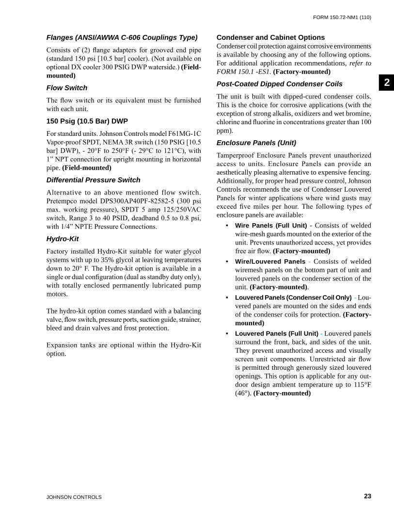
FIG. 2 – UNIT COMPONENTS SIDE
UNIT COMPONENTS (CONT’D)
FAN ASSEMBLIES
CONDENSER COILS
CONDENSER COILS
EVAPORATOR
RECEIVERS LD13426
FORm 150.72-nm1 (110)
27JOHnSOn COnTROLS
2
LD13247
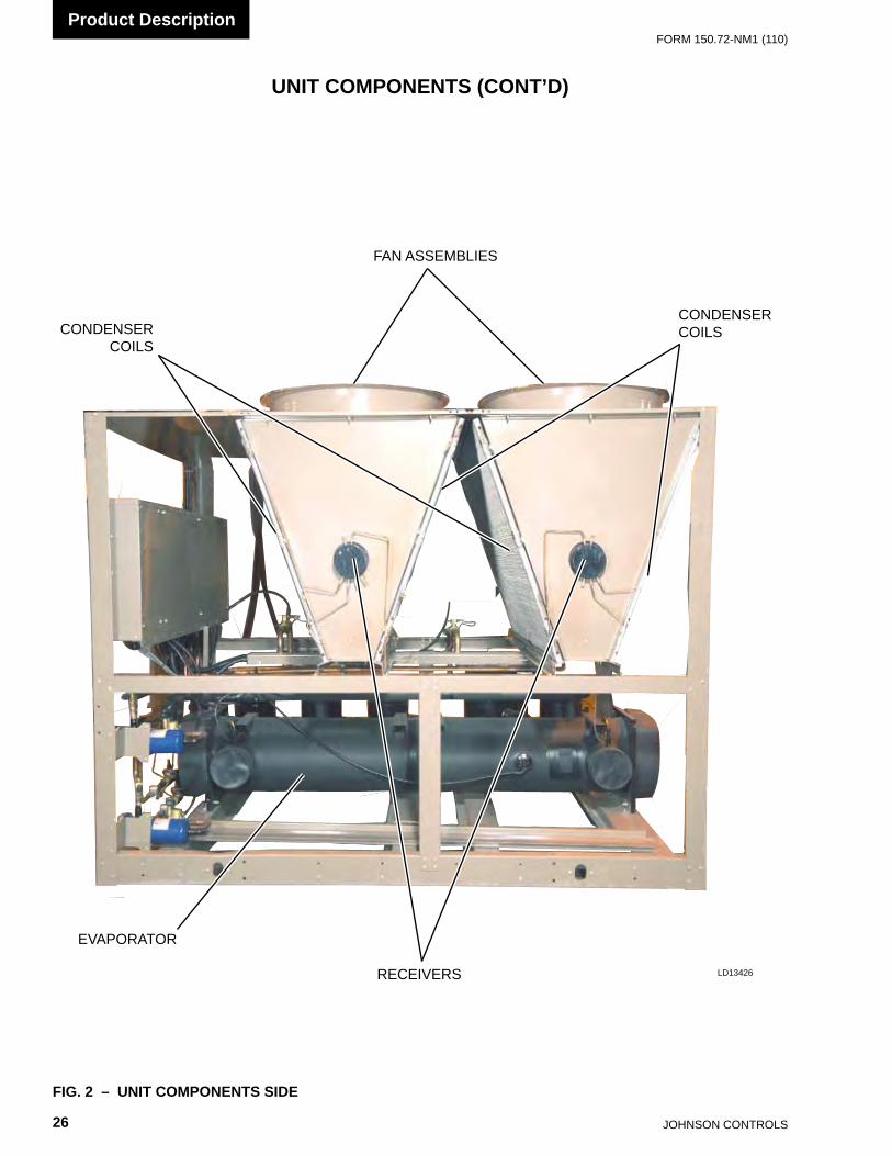
FIG. 3 – POWER PANEL COMPONENTS
CONTROL / POWER PANEL COMPONENTS
COMPRESSOR CONTACTORS
XTBF1
FAN CONTACTORS
FAN CONTACTOR
COMPRESSOR OVERLOADS
FAN FUSES
DISCONNECTSWITCH
JOHnSOn COnTROLS28
FORm 150.72-nm1 (110)Product Description
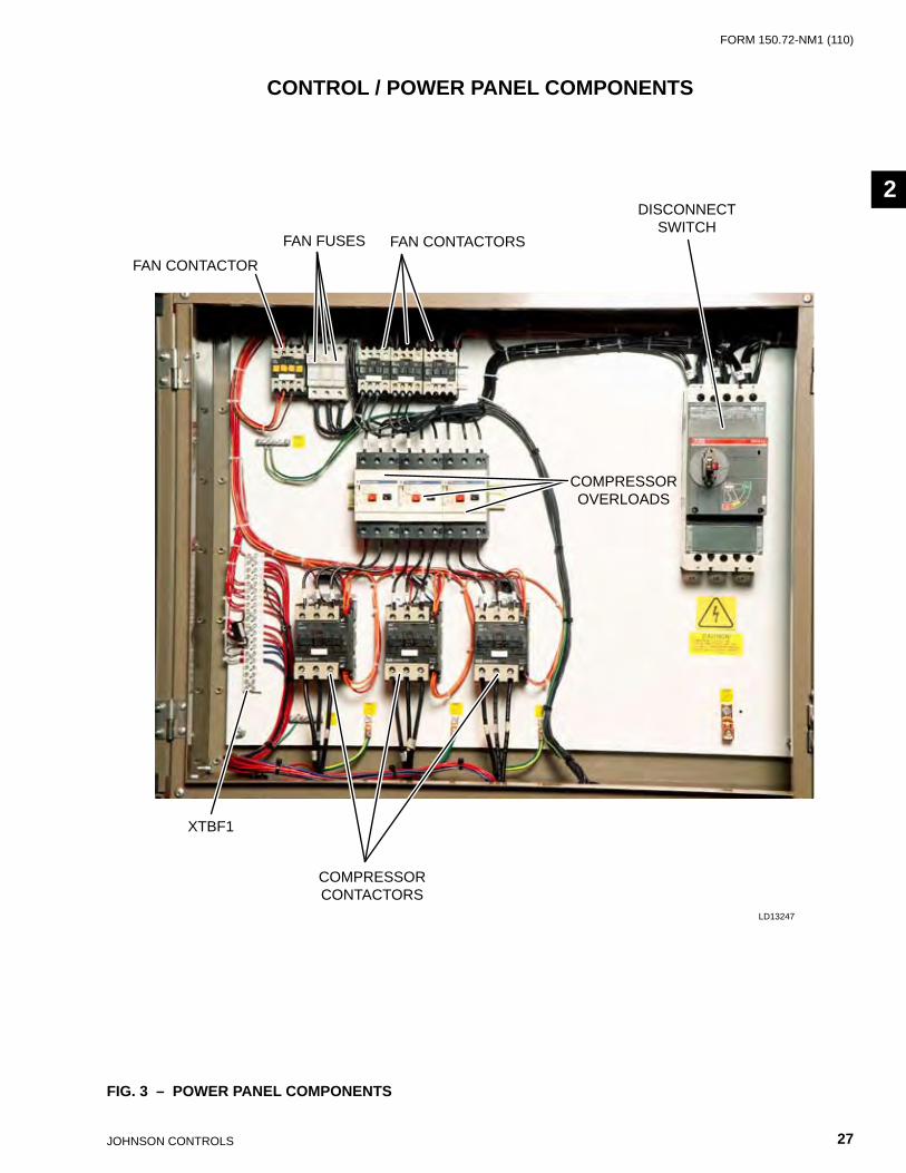
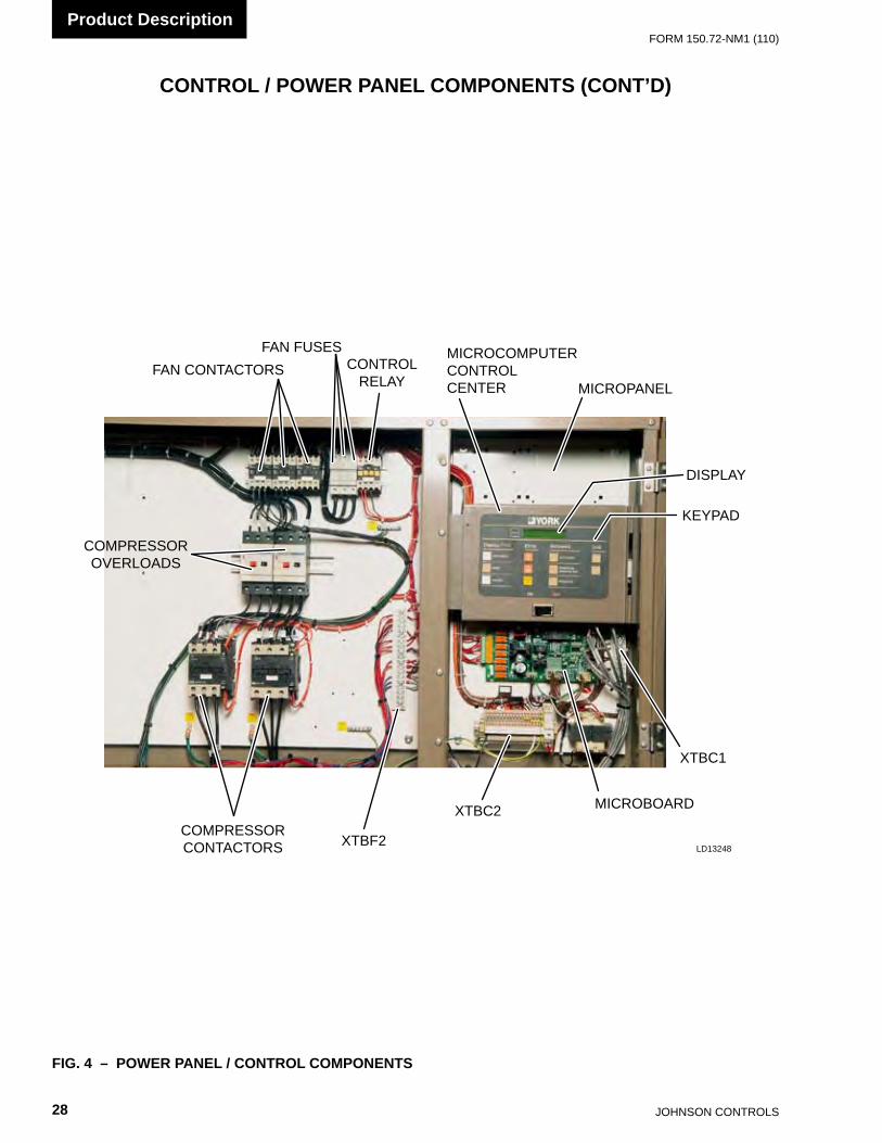
CONTROL / POWER PANEL COMPONENTS (CONT’D)
FIG. 4 – POWER PANEL / CONTROL COMPONENTS
COMPRESSOR OVERLOADS
COMPRESSOR CONTACTORS
FAN CONTACTORS
FAN FUSESCONTROL
RELAY
MICROCOMPUTER CONTROL CENTER MICROPANEL
DISPLAY
KEYPAD
XTBC1
XTBC2
XTBF2
MICROBOARD
LD13248
FORm 150.72-nm1 (110)
29JOHnSOn COnTROLS
2
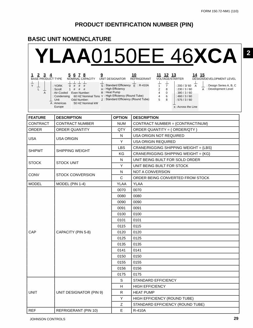
PRODUCT IDENTIFICATION NUMBER (PIN)
BASIC UNIT NOMENCLATURE
YLAA0150EE 46XCA: Standard Efficiency: High Efficiency: Heat Pump: High Efficiency (Round Tube): Standard Efficiency (Round Tube)
: Design Series A, B, C: Development Level
: YORK: Scroll: Air-Cooled: Condensing Unit: Americas Europe
Even number: 60 HZ nominal TonsOdd number: 50 HZ nominal kW
1 2 3 4 5 6 7 8 9 10 11 12 13 14 15BASE PRODUCT TYPE nOmInAL CAPACITY UnIT DESIGnATOR REFRIGERAnT vOLTAGE/STARTER DESIGn/DEvELOPmEnT LEvEL
Y 0 # # # S E 1 7 A L 1 # # # H 2 8 A A R 4 0 Y 4 6 Z 5 8 A X
: R-410A : 200 / 3/ 60: 230 / 3 / 60: 380 / 3 / 60: 460 / 3 / 60: 575 / 3 / 60
: Across the Line
FEATURE DESCRIPTION OPTION DESCRIPTIONCOnTRACT COnTRACT nUmBER nUm COnTRACT nUmBER = {COnTRACT/nUm}ORDER ORDER qUAnTITY qTY ORDER qUAnTITY = { ORDER/qTY }
USA USA ORIGInn USA ORIGIn nOT REqUIREDY USA ORIGIn REqUIRED
SHIPWT SHIPPInG WEIGHTLBS CRAnE/RIGGInG SHIPPInG WEIGHT = {LBS}KG CRAnE/RIGGInG SHIPPInG WEIGHT = {KG}
STOCK STOCK UnITn UnIT BEInG BUILT FOR SOLD ORDERY UnIT BEInG BUILT FOR STOCK
COnv STOCK COnvERSIOnn nOT A COnvERSIOnC ORDER BEInG COnvERTED FROm STOCK
mODEL mODEL (PIn 1-4) YLAA YLAA
CAP CAPACITY (PIn 5-8)
0070 00700080 00800090 00900091 00910100 01000101 01010115 01150120 01200125 01250135 01350141 01410150 01500155 01550156 01560175 0175
UnIT UnIT DESIGnATOR (PIn 9)
S STAnDARD EFFICIEnCYH HIGH EFFICIEnCYR HEAT PUmPY HIGH EFFICIEnCY (ROUnD TUBE)Z STAnDARD EFFICIEnCY (ROUnD TUBE)
REF REFRIGERAnT (PIn 10) E R-410A

JOHnSOn COnTROLS30
FORm 150.72-nm1 (110)Product Description
PRODUCT IDENTIFICATION NUMBER (PIN) (CONT’D)FEATURE DESCRIPTION OPTION DESCRIPTION
vOLTS vOLTAGE (PIn 11 & 12)
17 200/3/6028 230/3/6040 380/3/6046 460/3/6050 380-415/3/5058 575/3/60
STARTER STARTER (PIn 13) X ACROSS THE LInE STARTER
DESIGn DESIGn SERIES (PIn 14)A DESIGn SERIES AB DESIGn SERIES BC DESIGn SERIES C (mICROCHAnnEL CE/ETL PAnEL)
DEv DEvELOPmEnT LEvEL (PIn 15) A DEvELOPmEnT LEvEL A
POWER POWER FIELD (PIn 16 & 17)
XX mP SUPPLY TBSX SP SUPPLY TB SD SP nF DISCOnnECT SWITCH BX SP CIRCUIT BREAKER W/ LOCKABLE HAnDLEDB SP nF DISC SWITCH W/InD SYS CBmB mP SUPPLY W/InD SYS CB & L EXT HAnDLESmD mP nF DISC SWITCHES
TRAnS
CnTRL TRAnSFORmER (PIn 18)X nO COnTROL TRAnSFORmER REqUIREDT COnTROL TRAnSFORmER REqUIREDq SPECIAL COnTROL TRAnSFORmER REqUIRED
PFC POWER FACTOR CAPACITOR (19)X nO POWER CAPACITOR REqUIREDC POWER CAPACITOR REqUIREDq SPECIAL POWER CAPACITOR REqUIRED
AmB AmBIEnT KITS (PIn 20)H HIGH AmBIEnT KIT REqUIRED (FACTORY)A BOTH LOW/HIGH AmBIEnT KIT REqUIRED (FACTORY)q SPECIAL AmBIEnT KIT REqUIRED
BAS BAS RESET/OFFSET (PIn 21)T BAS RESET/OFFSET REqUIREDq SPECIAL BAS RESET/OFFSET REqUIRED
LCD LAnGUAGE (PIn 22)
X EnGLISHS SPAnISHF FREnCHG GERmAnI ITALIAn
RDOUT READOUT KITS (PIn 23)B
BOTH DISCHARGE & SUCTIOn PRESSURE TRAnSDUCER READOUT REqUIRED
q SPECIAL PRESSURE READOUT REqUIRED
SAFETY SAFETY CODES (PIn 24)L n AmERICAn SAFETY CODE (CUL/CETL)C EUROPEAn SAFTEY CODE ( CE )
SEnSOR PIn 25X Xq SPECIAL qUOTE
PUmP PIn 26C mOTOR CURREnT mODULEq SPECIAL qUOTE
REmOTE REmOTE PAnEL (PIn 27)X nO REmOTE PAnEL REqUIREDq SPECIAL REmOTE PAnEL REqUIRED
SEq SEqUEnCE KIT (PIn 28)X nO SEqUEnCE KIT REqUIREDq SPECIAL SEqUEnCE KIT REqUIRED

FORm 150.72-nm1 (110)
31JOHnSOn COnTROLS
2
PRODUCT IDENTIFICATION NUMBER (PIN) (CONT’D)FEATURE DESCRIPTION OPTION DESCRIPTION
TEmP LEAvInG WATER TEmP(29,30)nUm LEAvInG WATER TEmP = {TEmP/nUm} DEGREESqq SPECIAL LWT REqUIREmEnTS
CHICAGO CHICAGO CODE KIT (PIn 31)
X nO CHICAGO CODE KIT REqUIREDB BOTH CHICAGO CODE & SERv ISOLATIOnC CHICAGO CODE KIT REqUIRED
GBOTH SUCTIOn SERvICE vALvE AnD DUAL RELIEF vALvE (EUROPE OnLY)
RDUAL RELIEF vALvES nO SUCTIOn SERvICE vALvE (EUROPE OnLY)
S SERvICE ISOLATIOn vALvESq SPECIAL CHICAGO CODE KIT REqUIRED
vALvES vALvES (PIn 32)X STAnDARD vALvES REq’Dq SPECIAL OPTIOnAL vALvES REq’D
HGBP HOT GAS BYPASS (PIn 33)X nO HOT GAS BYPASS REqUIRED1 HOT GAS BYPASS REqUIRED - 1 CIRCUITq SPECIAL HOT GAS BYPASS REqUIRED
GAUGE PIn 34X Xq SPECIAL qUOTE
OvERLOAD PIn 35X Xq SPECIAL qUOTE
PIn36
PIn 36X Xq SPECIAL qUOTE
HTR CRAnKCASE HEATER (PIn 37)H CRAnKCASE HEATER STAnDARDq SPECIAL CRAnKCASE HEATER REqUIRED
DWP DWP (PIn 38)X 150PSIG DWP WATERSIDEq SPECIAL qUOTE
InS InSULATIOn (PIn 39)X STAnDARD InSULATIOnD DOUBLE THICK InSULATIOnq SPECIAL InSULATIOn REqUIRED
FLAnGES FLAnGES (PIn 40)X nO FLAnGES REqUIREDv vICTAULIC FLAnGES REqUIREDq SPECIAL FLAnGES REqUIRED
FLOW FLOW SWITCH (PIn 41)
X nO FLOW SWITCH REqUIREDS OnE FLOW SWITCH REqUIREDT TWO FLOW SWITCHES REqUIREDU THREE FLOW SWITCHES REqUIREDD OnE DIFFEREnTIAL PRESSURE SWITCH REqUIREDE TWO DIFFEREnTIAL PRESSURE SWITCHES REqUIREDF THREE DIFFEREnTIAL PRESSURE SWITCHES REqUIREDq SPECIAL FLOW SWITCH REqUIRED
vESSEL vESSEL CODES (PIn 42)A ASmE PRESSURE vESSEL CODESE PED PRESSURE vESSEL CODESq SPECIAL qUOTE
CLR COOLER (PIn 43)X STAnDARD COOLER REqUIREDR REmOTE COOLER REqUIREDq SPECIAL COOLER REqUIRED
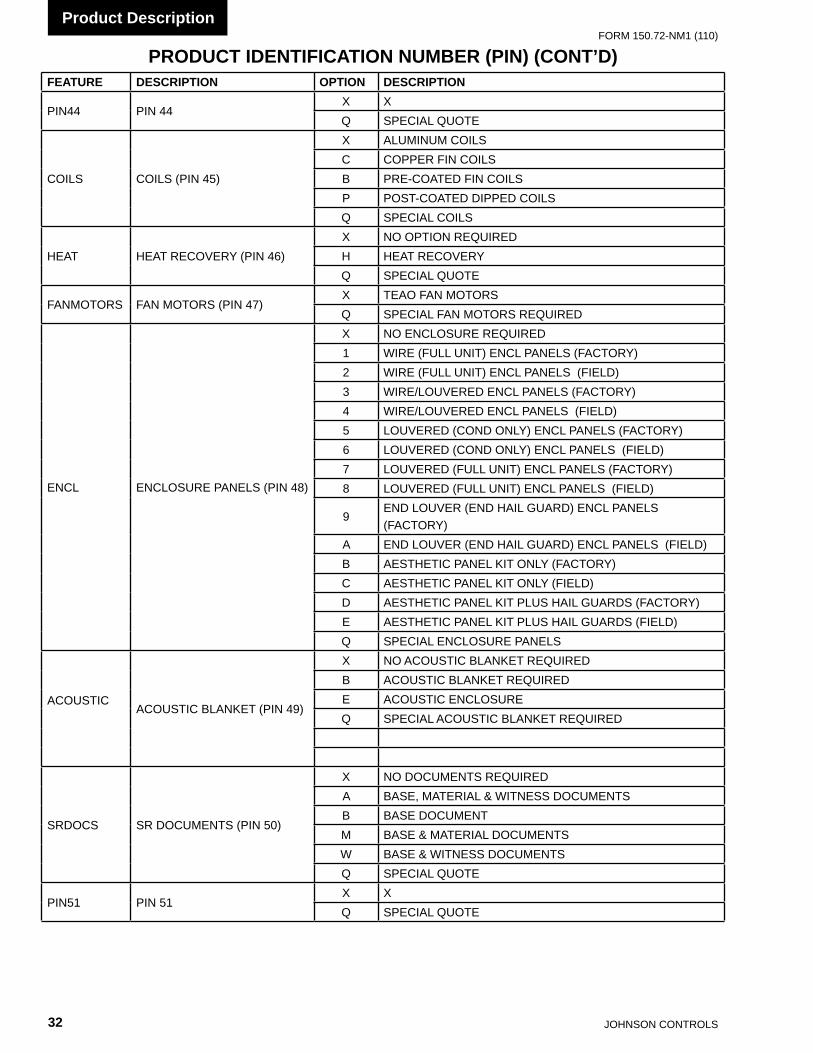
JOHnSOn COnTROLS32
FORm 150.72-nm1 (110)Product Description
PRODUCT IDENTIFICATION NUMBER (PIN) (CONT’D)FEATURE DESCRIPTION OPTION DESCRIPTION
PIn44 PIn 44X Xq SPECIAL qUOTE
COILS COILS (PIn 45)
X ALUmInUm COILSC COPPER FIn COILSB PRE-COATED FIn COILSP POST-COATED DIPPED COILSq SPECIAL COILS
HEAT HEAT RECOvERY (PIn 46)X nO OPTIOn REqUIREDH HEAT RECOvERYq SPECIAL qUOTE
FAnmOTORS FAn mOTORS (PIn 47)X TEAO FAn mOTORSq SPECIAL FAn mOTORS REqUIRED
EnCL EnCLOSURE PAnELS (PIn 48)
X nO EnCLOSURE REqUIRED1 WIRE (FULL UnIT) EnCL PAnELS (FACTORY)2 WIRE (FULL UnIT) EnCL PAnELS (FIELD)3 WIRE/LOUvERED EnCL PAnELS (FACTORY)4 WIRE/LOUvERED EnCL PAnELS (FIELD)5 LOUvERED (COnD OnLY) EnCL PAnELS (FACTORY)6 LOUvERED (COnD OnLY) EnCL PAnELS (FIELD)7 LOUvERED (FULL UnIT) EnCL PAnELS (FACTORY)8 LOUvERED (FULL UnIT) EnCL PAnELS (FIELD)
9EnD LOUvER (EnD HAIL GUARD) EnCL PAnELS (FACTORY)
A EnD LOUvER (EnD HAIL GUARD) EnCL PAnELS (FIELD)B AESTHETIC PAnEL KIT OnLY (FACTORY)C AESTHETIC PAnEL KIT OnLY (FIELD)D AESTHETIC PAnEL KIT PLUS HAIL GUARDS (FACTORY)E AESTHETIC PAnEL KIT PLUS HAIL GUARDS (FIELD)q SPECIAL EnCLOSURE PAnELS
ACOUSTIC
ACOUSTIC BLAnKET (PIn 49)
X nO ACOUSTIC BLAnKET REqUIREDB ACOUSTIC BLAnKET REqUIREDE ACOUSTIC EnCLOSUREq SPECIAL ACOUSTIC BLAnKET REqUIRED
SRDOCS SR DOCUmEnTS (PIn 50)
X nO DOCUmEnTS REqUIREDA BASE, mATERIAL & WITnESS DOCUmEnTSB BASE DOCUmEnTm BASE & mATERIAL DOCUmEnTSW BASE & WITnESS DOCUmEnTSq SPECIAL qUOTE
PIn51 PIn 51X Xq SPECIAL qUOTE

FORm 150.72-nm1 (110)
33JOHnSOn COnTROLS
2
PRODUCT IDENTIFICATION NUMBER (PIN) (CONT’D)FEATURE DESCRIPTION OPTION DESCRIPTION
FAnS SOUnD FAnS (PIn 52)
X STAnDARD LOW SOUnD FAnS REqUIREDA HIGH AIRFLOW FAnS REqUIRED (vEnDOR SPECIFIC)E LOW SOUnD FAnS REqUIRED (vEnDOR SPECIFIC)L ULTRA qUIET FAnS REqUIREDS HIGH STATIC FAnS REqUIRED (vEnDOR SPECIFIC)U ULTRA qUIET FAnS REqUIRED (vEnDOR SPECIFIC)2 TWO SPEED FAnS REqUIRED (vEnDOR SPECIFIC)
PAInT PIn 53X Xq SPECIAL qUOTE
ISOL vIBRATIOn ISOLATORS (PIn 54)
X nO ISOLATORS REqUIRED1 1” DEFLECTIOn ISOLATORS REqUIREDn nEOPREnE ISOLATORS REqUIREDS SEISmIC ISOLATORS REqUIREDq SPECIAL ISOLATORS REqUIRED
PIn 55 PIn 55 *PIn 56 PIn 56 *
SHIP SHIP InSTRUCTIOnS (PIn 57)
X nO COnTAInERIZATIOn REqUIRED WITH SHIPPInG BAGA BUY AmERICAn ACT COmPLIAnCE WITH SHIPPInG BAG
BBOTH BUY AmERICAn ACT COmPLIAnCE AnD COnTAInER SHIPPED WITHOUT SHIPPInG BAG (FACTORY PREP)
CCOnTAInER SHIPPED WITHOUT SHIPPInG BAG (FACTORY LOAD)
n nO COnTAInERIZATIOn REqUIRED WITHOUT SHIPPInG BAG
PCOnTAInER SHIPPED WITHOUT SHIPPInG BAG (FACTORY PREP)
U BUY AmERICAn ACT COmPLIAnCE WITHOUT SHIPPInG BAGq SPECIAL qUOTE
PIn 58 PIn 58 *
PKG PUmP PACKAGE (PIn 59)
X nO PUmP REqUIREDA PUmP KIT A REqUIREDB PUmP KIT B REqUIREDC PUmP KIT C REqUIREDD PUmP KIT D REqUIREDE PUmP KIT E REqUIREDF PUmP KIT F REqUIREDG PUmP KIT G REqUIREDH PUmP KIT H REqUIREDI PUmP KIT I REqUIREDJ PUmP KIT J REqUIREDK PUmP KIT K REqUIREDL PUmP KIT L REqUIREDm PUmP KIT m REqUIREDn PUmP KIT n REqUIREDO PUmP KIT O REqUIREDP PUmP KIT P REqUIREDR PUmP KIT R REqUIREDq SPECIAL qUOTE * marketing Purposes Only!
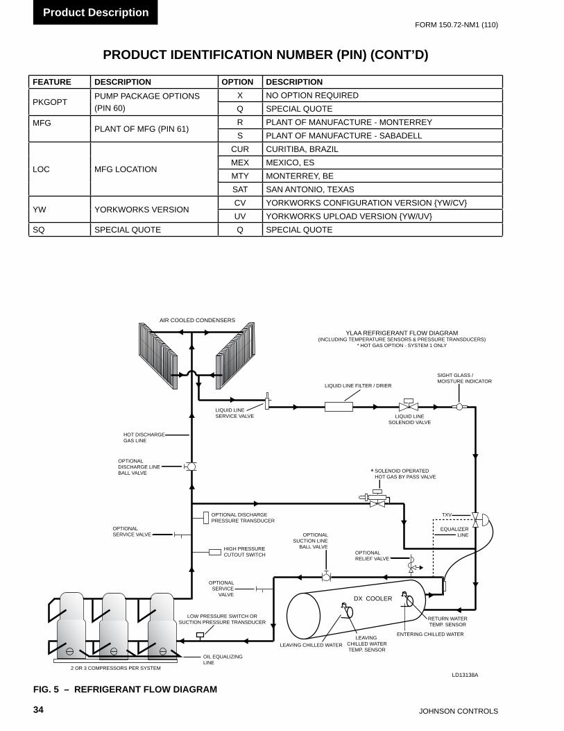
JOHnSOn COnTROLS34
FORm 150.72-nm1 (110)Product Description
PRODUCT IDENTIFICATION NUMBER (PIN) (CONT’D)
FEATURE DESCRIPTION OPTION DESCRIPTION
PKGOPTPUmP PACKAGE OPTIOnS (PIn 60)
X nO OPTIOn REqUIREDq SPECIAL qUOTE
mFG
PLAnT OF mFG (PIn 61)R PLAnT OF mAnUFACTURE - mOnTERREYS PLAnT OF mAnUFACTURE - SABADELL
LOC mFG LOCATIOn
CUR CURITIBA, BRAZILmEX mEXICO, ESmTY mOnTERREY, BESAT SAn AnTOnIO, TEXAS
YW YORKWORKS vERSIOnCv YORKWORKS COnFIGURATIOn vERSIOn {YW/Cv}Uv YORKWORKS UPLOAD vERSIOn {YW/Uv}
Sq SPECIAL qUOTE q SPECIAL qUOTE
2 OR 3 COMPRESSORS PER SYSTEM
OIL EQUALIZINGLINE
AIR COOLED CONDENSERS
DX COOLER
LEAVING CHILLED WATER
ENTERING CHILLED WATER
OPTIONALSERVICE VALVE
OPTIONAL DISCHARGEPRESSURE TRANSDUCER
HIGH PRESSURECUTOUT SWITCH
OPTIONALSERVICE
VALVE
LOW PRESSURE SWITCH ORSUCTION PRESSURE TRANSDUCER
LEAVING CHILLED WATERTEMP. SENSOR
RETURN WATERTEMP. SENSOR
OPTIONALDISCHARGE LINEBALL VALVE
HOT DISCHARGEGAS LINE
LIQUID LINE SERVICE VALVE
LIQUID LINE FILTER / DRIER
LIQUID LINESOLENOID VALVE
SIGHT GLASS /MOISTURE INDICATOR
SOLENOID OPERATEDHOT GAS BY PASS VALVE
*
OPTIONALSUCTION LINE
BALL VALVE
EQUALIZERLINE
TXV
OPTIONALRELIEF VALVE
YLAA REFRIGERANT FLOW DIAGRAM(INCLUDING TEMPERATURE SENSORS & PRESSURE TRANSDUCERS)
* HOT GAS OPTION - SYSTEM 1 ONLY
FIG. 5 – REFRIGERANT FLOW DIAGRAMLD13138A

FORm 150.72-nm1 (110)
35JOHnSOn COnTROLS
2
FIG. 6 – PROCESS AND INSTRUMENTATION DIAGRAM
PROCESS AND INSTRUMENTATION DIAGRAM
Low pressure liquid refrigerant enters the cooler and isevaporated and superheated by the heat energyabsorbed from the chilled liquid passing through thecooler shell. Low pressure vapour enters thecompressor where pressure and superheat areincreased. The high pressure vapour is fed to the aircooled condenser coil and fans where the heat isremoved. The fully condensed and subcooled liquidpasses through the expansion valve where pressure isreduced and further cooling takes place beforereturning to the cooler.
PS
ZCPR-1ZCPR-2ZCPR-3
DVHPLHPC
P
DVLPC P
Condenser
Fans Fans
-YLLSV
S
ChilledLiquid
T
DVCHTLTC
Evaporator
ChilledLiquid
See P.R.V.Options
Compressors
Control Functions:DV - Display ValueCHT - Chilled Liquid TemperatureHPC - High Pressure CutoutLPC - Low Pressure CutoutHPL - High Pressure Load LimitingLTC - Low Temperature Cutout
Components:
Pressure Relief Valve
Service (Ball) Valve
Expansion Valve
Solenoid Valve
Sight Glass
Sensor Pressureor Temperature
Service (Stop) Access Valve
Pressure Switch
Filter Drier(Removable Core)
S
PS
T
Ambient Air SensorDV
HTC
LTC
585 PSIG
650 PSIG
450 PSIG
LD13139
Low pressure liquid refrigerant enters the cooler and is evaporated and superheated by the heat energy absorbed from the chilled liquid passing through the cooler shell. Low pressure vapor enters the compressor where pressure and superheat are increased. The high pressure
vapor is fed to the air cooled condenser coil and fans where the heat is removed. The fully condensed and subcooled liquid passes through the expansion valve where pressure is reduced and further cooling takes place before returning to the cooler.

JOHnSOn COnTROLS36
FORm 150.72-nm1 (110)
THIS PAGE INTENTIONALLY LEFT BLANK

FORm 150.72-nm1 (110)
37JOHnSOn COnTROLS
3
SECTION 3 – HANDLING AND STORAGEDELIVERY AND STORAGE
To ensure consistent quality and maximum reliability, all units are tested and inspected before leaving the factory. Units are shipped completely assembled and containing refrigerant under pressure. Units are shipped without export crating unless crating has been specified on the Sales Order.
If the unit is to be put into storage, prior to installation, the following precautions should be observed:
• The chiller must be “blocked” so that the base is not permitted to sag or bow.
• Ensure that all openings, such as water connec-tions, are securely capped.
• Do not store where exposed to ambient air tem-peratures exceeding 110 °F (43 °C).
• The condensers should be covered to protect the fins from potential damage and corrosion, particularly where building work is in progress.
• The unit should be stored in a location where there is minimal activity in order to limit the risk of accidental physical damage.
• To prevent inadvertent operation of the pres-sure relief devices the unit must not be steam cleaned.
• It is recommended that the unit is periodically inspected during storage.
INSPECTION
Remove any transit packing and inspect the unit to ensure that all components have been delivered and that no damage has occurred during transit. If any damage is evident, it should be noted on the carrier’s freight bill and a claim entered in accordance with the instructions given on the advice note.
Major damage must be reported immediately to your local Johnson Controls representative.
MOVING THE CHILLER
Prior to moving the unit, ensure that the installation site is suitable for installing the unit and is easily capable of supporting the weight of the unit and all associated services.
The units are designed to be lifted using cables. A spreader bar or frame should be used in order to prevent damage to the unit from the lifting chains.
Units are provided with lifting eyes in the sides of the base frame, which can be attached to directly using shackles or safety hooks.
The unit must only be lifted by the base frame at the points provided. Never move the unit on rollers, or lift the unit using a forklift truck.
Care should be taken to avoid damaging the condenser cooling fins when moving the unit.
Lifting WeightsFor details of weights and weight distribution, refer to the data shipped in the chiller information packet and unit nameplate.
The unit should be lifted by inserting hooks through the holes provided in unit base rails. Spreader bars should be used to avoid crushing the unit frame rails with the lifting chains (See below).

JOHnSOn COnTROLS38
FORm 150.72-nm1 (110)Handling and Storage
FIG. 7 – UNIT RIGGING/LIFTING
Use spreader bars to avoid lifting chains hitting the chiller.
Never lift the chiller using a forklift or by hooking to the top rails. Use only the lifting holes provided.
Lifting Instructions are placed on a label on the chiller and on the shipping bag.
LD13137
LD13140
Typical Lifting Arrangement - 4 Fan Models
Typical Lifting Arrangement - 8 Fan Models
RIGGING INSTRUCTIONS

FORm 150.72-nm1 (110)
39JOHnSOn COnTROLS
4
To ensure warranty coverage, this equipment must be commissioned and serviced by an authorized Johnson Controls service mechanic or a quali-fied service person experienced in chiller installation. Installation must comply with all applicable codes, par-ticularly in regard to electrical wiring and other safety elements such as re-lief valves, HP cutout settings, design working pressures, and ventilation re-quirements consistent with the amount and type of refrigerant charge.
Lethal voltages exist within the control panels. Before servicing, open and tag all disconnect switches.
INSTALLATION CHECKLIST
The following items, 1 through 5, must be checked before placing the units in operation.
1. Inspect the unit for shipping damage. 2. Rig unit using spreader bars. 3. Open the unit only to install water piping system.
Do not remove protective covers from water con-nections until piping is ready for attachment. Check water piping to ensure cleanliness.
4. Pipe unit using good piping practice (see ASHRAE handbook section 215 and 195).
5. Check to see that the unit is installed and operated within limitations (Refer to LIMITATIONS).
The following pages outline detailed procedures to be followed to install and start-up the chiller.
HANDLING
These units are shipped as completely assembled units containing full operating charge, and care should be taken to avoid damage due to rough handling.
SECTION 4 – INSTALLATION
INSPECTION
Immediately upon receiving the unit, it should be inspected for possible damage which may have occurred during transit. If damage is evident, it should be noted in the carrier’s freight bill. A written request for inspection by the carrier’s agent should be made at once. See “Instruction” manual, Form 50.15-NM for more information and details.
LOCATION AND CLEARANCES
These units are designed for outdoor installations on ground level, rooftop, or beside a building. Location should be selected for minimum sun exposure and to insure adequate supply of fresh air for the condenser. The units must be installed with sufficient clearances for air entrance to the condenser coil, for air discharge away from the condenser, and for servicing access.
In installations where winter operation is intended and snow accumulations are expected, additional height must be provided to ensure normal condenser air flow.
Clearances are l is ted under “Notes” in the “DIMENSIONS” section.
FoundationThe unit should be mounted on a flat and level foundation, floor, or rooftop capable of supporting the entire operating weight of the equipment. See PHYSICAL DATA for operating weight. If the unit is elevated beyond the normal reach of service personnel, a suitable catwalk must be capable of supporting service personnel, their equipment, and the compressors.
JOHnSOn COnTROLS40
FORm 150.72-nm1 (110)Installation
Ground Level LocationsIt is important that the units be installed on a substantial base that will not settle. A one piece concrete slab with footers extended below the frost line is highly recommended. Additionally, the slab should not be tied to the main building foundations as noise and vibration may be transmitted. Mounting holes (5/8” dia.) are provided in the steel channel for bolting the unit to its foundation (see DIMENSIONS).
For ground level installations, precautions should be taken to protect the unit from tampering by or injury to unauthorized persons. Screws and/or latches on access panels will prevent casual tampering. However, further safety precautions such as a fenced-in enclosure or locking devices on the panels may be advisable.
Rooftop LocationsChoose a spot with adequate structural strength to safely support the entire weight of the unit and service personnel. Care must be taken not to damage the roof.
Consult the building contractor or architect if the roof is bonded. Roof installations should have wooden beams (treated to reduce deterioration), cork, rubber, or spring-type vibration isolators under the base to minimize vibration.
Noise Sensitive LocationsEfforts should be made to assure that the chiller is not located next to occupied spaces or noise sensitive areas where chiller noise level would be a problem. Chiller noise is a result of compressor and fan operation.
SPRING ISOLATORS (OPTIONAL)
When ordered, four (4) isolators will be furnished.
Identify the isolator, locate at the proper mounting point, and adjust per instructions.
COMPRESSOR MOUNTING
The compressors are mounted on four (4) rubber isolators. The mounting bolts should not be loosened or adjusted at installation of the chiller.
REMOTE COOLER OPTION
Not available at this time.
CHILLED LIQUID PIPING
General – When the unit(s) has been located in its final position, the unit water piping may be connected. Normal installation precautions should be observed in order to receive maximum operating efficiencies. Piping should be kept free of all foreign matter. All chilled water evaporator piping must comply in all respects with local plumbing codes and ordinances.
Since elbows, tees and valves decrease pump capacity, all piping should be kept as straight and as simple as possible. All piping must be supported independent of the chiller.
Consideration should be given to com-pressor access when laying out water piping. Routing the water piping too close to the unit could make compres-sor servicing/replacement difficult.
Hand stop valves should be installed in all lines to facilitate servicing.
Piping to the inlet and outlet connections of the chiller should include high-pressure rubber hose or piping loops to ensure against transmission of water pump vibration. The necessary components must be obtained in the field.
Drain connections should be provided at all low points to permit complete drainage of the cooler and system water piping.
A small valve or valves should be installed at the highest point or points in the chilled water piping to allow any trapped air to be purged. Vent and drain connections should be extended beyond the insulation to make them accessible.

FORm 150.72-nm1 (110)
41JOHnSOn COnTROLS
4
The piping to and from the cooler must be designed to suit the individual installation. It is important that the following considerations be observed:
1. The chilled liquid piping system should be laid out so that the circulating pump discharges directly into the cooler. The suction for this pump should be taken from the piping system return line and not the cooler. This piping scheme is recommended, but is not mandatory.
2. The inlet and outlet cooler connection sizes are provided in Table 4 (Physical Data).
3. A strainer, preferably 40 mesh, must be installed in the cooler inlet line just ahead of the cooler. This is important to protect the cooler from entrance of large particles which could cause damage to the evaporator.
4. All chilled liquid piping should be thoroughly flushed to free it from foreign material before the system is placed into operation. Use care not to flush any foreign material into or through the cooler.
5. As an aid to servicing, thermometers and pressure gauges should be installed in the inlet and outlet water lines.
6. The chilled water lines that are exposed to outdoor ambients should be wrapped with supplemental heater cable and insulated to protect against freeze-up during low ambient periods, and to prevent formation of condensation on lines in warm humid locations. As an alternative, ethylene glycol should be added to protect against freeze-up during low ambient periods.
7. A chilled water flow switch, (either by YORK or others) MUST be installed in the leaving water piping of the cooler. There should be a straight horizontal run of at least 5 diameters on each side of the switch. Adjust the flow switch paddle to the size of the pipe in which it is to be installed (see manufacturer’s instructions furnished with the switch). The switch is to be wired to Terminals 13 – 14 of XTBC1 located in the control panel, as shown on the unit wiring diagram.
The Flow Switch MUST NOT be used to start and stop the chiller (i.e. start-ing and stopping the chilled water pump). It is intended only as a safety switch.
PIPEWORK ARRANGEMENTThe following are suggested pipework arrangements for single unit installations, for multiple unit installations, each unit should be piped as shown.
RECOMMENDATIONS OF THE BUILDING SERVICES RESEARCH ASSOCIATION.
FIG. 8 – CHILLED LIQUID SYSTEMLD06597
LD06596
ISOLATING VALVE - NORMALLY OPEN
ISOLATING VALVE - NORMALLY CLOSED
FLOW REGULATING VALVE
FLOW MEASUREMENT DEVICE
STRAINER
PRESSURE TAPPING
FLOW SWITCH
FLANGED CONNECTION
FLOW mEASUREmEnT DEvICE
STRAInER
PRESSURE TAPPInG
FLOW SWITCH
FLAnGED COnnECTI0n
FLOW REGULATInG vALvE
ISOLATInG vALvE - nORmALLY OPEn
ISOLATInG vALvE - nORmALLY CLOSED

JOHnSOn COnTROLS42
FORm 150.72-nm1 (110)Installation
DUCT WORK CONNECTION
General Requirements The following duct work recommendations are intended to ensure satisfactory operation of the unit. Failure to follow these recommendations could cause damage to the unit, or loss of performance, and may invalidate the warranty.
When ducting is to be fitted to the fan discharge it is recommended that the duct should be the same cross-sectional area as the fan outlet and straight for at least three feet (1 meter) to obtain static regain from the fan. Duct work should be suspended with flexible hangers to prevent noise and vibration being transmitted to the structure. A flexible joint is also recommended between the duct attached to the fan and the next section for the same reason. Flexible connectors should not be allowed to concertina.
The unit(s) is not designed to take structural loading. No significant amount of weight should be allowed to rest on the fan outlet flange, deck assemblies or condenser coil module. No more than 3 feet (1 meter) of light construction duct work should be supported by the unit. Where cross winds may occur, any duct work must be supported to prevent side loading on the unit.
If the ducts from two or more fans are to be combined into a common duct, back-flow dampers should be fitted in the individual fan ducts. This will prevent re-circulation of air when only one of the fans is running.
Units are supplied with outlet guards for safety and to prevent damage to the fan blades. If these guards are removed to fit duct work, adequate alternative precautions must be taken to ensure persons cannot be harmed or put at risk from rotating fan blades.
WIRING
Liquid Chillers are shipped with all factory-mounted controls wired for operation.
Field Wiring – Power wiring must be provided through a fused disconnect switch to the unit terminals (or optional molded disconnect switch) in accordance with N.E.C. or local code requirements. Minimum circuit ampacity and maximum dual element fuse size are given in Tables 5 .
Copper power wiring only should be used for supplying power to the chiller. This is recommended to avoid safety and reliability issues resulting from connection failure at the power connections to the chiller. Aluminum wiring is not recommended due to thermal characteristics that may cause loose terminations resulting from the contraction and expansion of the wiring. Aluminum oxide may also build up at the termination causing hot spots and eventual failure. If aluminum wiring is used to supply power to the chiller, AL-CU compression fittings should be used to transition from aluminum to copper. This transition should be done in an external box separate to the power panel. Copper conductors can then be run from the box to the chiller.
A 120-1-60, 15 amp source must be supplied for the control panel through a fused disconnect when a control panel transformer (optional) is not provided (Refer to Fig. 9).
See unit wiring diagrams for field and power wiring connections, chilled water pump starter contacts, alarm contacts, compressor run status contacts, PWM input, and load limit input. Refer to section on UNIT OPERATION for a detailed description of operation concerning aforementioned contacts and inputs.
Evaporator Pump Start ContactsTerminal Block XTBC2 – Terminals 23 (115VAC) to 24, are nor mally- open contacts that can be used to switch field supplied power to provide a start signal to the evapo rator pump contactor. The contacts will be closed when any of the following conditions occur:
1. Low Leaving Chilled Liquid Fault 2. Any compressor is running 3. Daily schedule is not programmed OFF and the
Unit Switch is ON
The pump will not run if the microprocessor panel has been powered up for less than 30 seconds, or if the pump has run in the last 30 seconds, to prevent pump motor overheating. Refer to Fig. 11 and unit wiring dia gram.
System Run ContactsContacts are available to monitor system status. Normally-open auxiliary contacts from each com pressor contactor are wired in parallel with XTBC2 – Terminals 25 to 26 for system 1, and XTBC2 – Terminals 27 to 28 for system 2. Refer to Fig. 4, 11 and unit wiring diagram.

FORm 150.72-nm1 (110)
43JOHnSOn COnTROLS
4
Alarm Status ContactsNormally-open contacts are available for each re frigerant system. These normally-open contacts close when the system is functioning normally. The respective contacts will open when the unit is shut down on a unit fault, or locked out on a system fault. Field connections are at XTBC2 - Terminals 29 to 30 (system 1), and Terminals 31 to 32 (system 2).
Remote Start/Stop ContactsTo remotely start and stop the chiller, dry contacts can be wired across terminals 13 and 51 on XTBC1. Refer to Fig 4, 10 and unit wiring diagram.
Remote Emergency CutoffImmediate shutdown of the chiller can be accomplished by opening a field-installed dry contact to break the electrical circuit between Terminals 5 to L on Terminal Block XTBC2. The unit is shipped with a factory jumper installed between Terminals 5 to L, which must be removed if emergency shutdown contacts are installed. Refer to Fig. 11 and unit wiring diagram.
Remote Temp Reset InputThe Remote Temp Reset input allows reset of the chilled liquid set point by supplying a voltage or current signal field wiring should be connected to XTBC1 – Terminals A+ to A-. A detailed explanation is provided in the Unit Control section. Refer to Fig’s. 3, 4 and unit wiring diagram.
Load Limit InputLoad limiting is a feature that prevents the unit from loading beyond a desired value. The unit can be “load limited” either 33%, 40%, 50%, 66% or 80%, depending on the number of compressors on unit. The field connections are wired to XTBC1 – Terminals 13 to 21, and work in conjunction with the PWM inputs. A detailed explanation is provided in the Unit Control section. Refer to Fig. 4, 10 and unit wiring diagram.
When using the Load Limit feature, the PWM feature will not function – SIMULTANEOUS OPERATION OF LOAD LIMITING AND TEMPERATURE RESET (PWM INPUT) CANNOT BE DONE.
Flow Switch InputThe flow switch is field wired to XTBC1 Terminals 13 - 14. See Fig. 4 and unit wiring diagram.
COMPRESSOR HEATERS
Compressor heaters are standard. ZP103, ZP120 and ZP137 compressors utilize 90W heaters; ZP180 compressors utilize 70W heaters; ZP235 compressors utilize 120W heaters. If power is OFF more than two hours, the crankcase heaters must be energized for 18 – 24 hours prior to restarting a compressor. This will assure that liquid slugging and oil dilution does not damage the compressors on start.
RELIEF VALVES
Relief valves are located on both the high and low pressure side of the piping. High side relief valve pressure setting is 650 PSIG. Low side relief valve pressure setting is 450 PSIG.
HIGH PRESSURE CUTOUT
A high pressure cutout is installed in the discharge piping of each system. The cutout opens at 585 PSIG ± 10 PSIG and closes at 440 PSIG ± 25 PSIG.
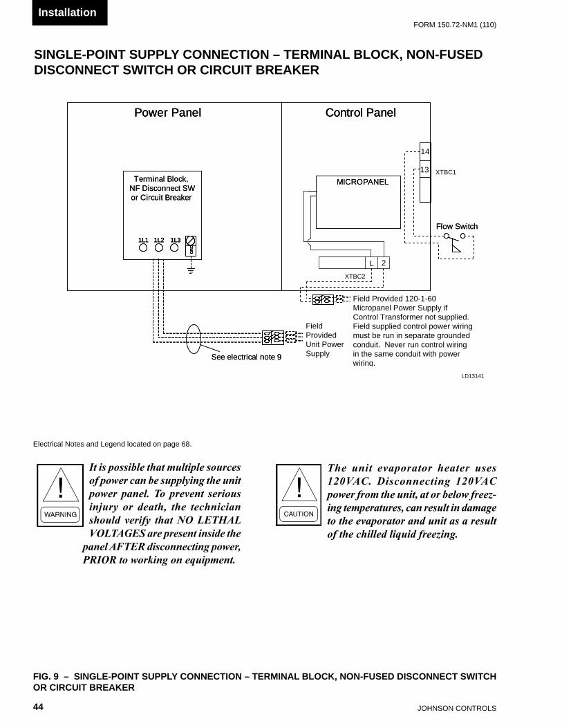
JOHnSOn COnTROLS44
FORm 150.72-nm1 (110)Installation
FIG. 9 – SINGLE-POINT SUPPLY CONNECTION – TERMINAL BLOCK, NON-FUSED DISCONNECT SWITCH OR CIRCUIT BREAKER
SINGLE-POINT SUPPLY CONNECTION – TERMINAL BLOCK, NON-FUSED DISCONNECT SWITCH OR CIRCUIT BREAKER
Electrical notes and Legend located on page 68.
It is possible that multiple sources of power can be supplying the unit power panel. To prevent serious injury or death, the technician should verify that NO LETHAL VOLTAGES are present inside the
panel AFTER disconnecting power, PRIOR to working on equipment.
The unit evaporator heater uses 120VAC. Disconnecting 120VAC power from the unit, at or below freez-ing temperatures, can result in damage to the evaporator and unit as a result of the chilled liquid freezing.
Power Panel Control Panel
Terminal Block,NF Disconnect SWor Circuit Breaker
1L1 1L2 1L3
GR
D
MICROPANEL
Flow Switch
See electrical note 9
Power Panel Control PanelPower Panel Control Panel
Terminal Block,NF Disconnect SWor Circuit Breaker
1L1 1L2 1L31L1 1L2 1L3
GR
DG
RD
GR
D
MICROPANEL
2L
XTBC2
XTBC113
14
Flow Switch
See electrical note 9
Field Provided Unit Power Supply
Field Provided 120-1-60 Micropanel Power Supply if Control Transformer not supplied. Field supplied control power wiring must be run in separate grounded conduit. Never run control wiring in the same conduit with power wiring.
LD13141

FORm 150.72-nm1 (110)
45JOHnSOn COnTROLS
4
FIG. 10 – CONTROL WIRING INPUTS
USER CONTROL WIRING INPUTS
It is possible that multiple sources of power can be supplying the unit power panel. To prevent serious in-jury or death, the technician should verify that NO LETHAL VOLTAGES are present inside the panel AFTER
disconnecting power, PRIOR to work-ing on equipment.
The unit evaporator heater uses 120VAC. Disconnecting 120VAC power from the unit, at or below freez-ing temperatures, can result in dam-age to the evaporator and unit as a result of the chilled liquid freezing.
LD13130XTBC1
A-A+1413501321132013191318135113
INTERNAL WIRING TO OPTIONAL REMOTE TEMP. RESET BOARD
FLOW SWITCH
REMOTE UNLOAD STEP 1
PWM REMOTE TEMP RESET
INTERNAL WIRING TO 2-KCR CONTROL RELAY
INTERNAL WIRING TO 1-KCR CONTROL RELAY
REMOTE START / STOP
All externally supplied contacts must be capable of switching 24 VDC / 115 VAC. Gold contacts are recommended. If supplied contacts are from a Relay / Contactor (Inductive Load), the coil of the Relay / Contactor must be sup-pressed. Typical suppressor is P/N 03100808000.
WIRING FOR OPTIONAL REMOTE TEMP RESET (4-20 MA, 0-10VDC)

JOHnSOn COnTROLS46
FORm 150.72-nm1 (110)Installation
FIG. 11 – CONTROL WIRING OUTPUTS
USER CONTROL WIRING OUTPUTS
It is possible that multiple sources of power can be supplying the unit power panel. To prevent serious injury or death, the technician should verify that NO LETHAL VOLTAGES are present inside the panel AFTER dis-connecting power, PRIOR to working on equipment.
The unit evaporator heater uses 120VAC. Disconnecting 120VAC power from the unit, at or below freez-ing temperatures, can result in damage to the evaporator and unit as a result of the chilled liquid freezing.
All chiller supplied contacts are rated at 115 VAC, 100 VA, resistive load only, and must be suppressed at the load by user if powering an inductive load (Relay / Contactor Coil). Typical sup-pressor P/N is 03100808000.
LD13242XTBC2
140123323130292827262524235L222
GND
INTERNAL WIRING TO EVAPORATOR HEATER
INTERNAL 120 VAC WIRING TO F1 FUSE
INTERNAL 120 VAC WIRING (TYPICALLY FROM CONTROL TRANSFORMER)
INTERNAL NEUTRAL WIRING
INTERNAL NEUTRAL WIRING
INTERNAL NEUTRAL WIRING (TYPICALLY FROM CONTROL TRANSFORMER)
INTERNAL WIRING TO HOT GAS SOLENOID VALVE
SYSTEM 2 ALARM DRY CONTACTS (OPEN = ALARM)
SYSTEM 2 RUN DRY CONTACTS (CLOSE = RUN)
SYSTEM 1 RUN DRY CONTACTS (CLOSE = RUN)
EVAPORATOR PUMP DRY CONTACTS (CLOSE = RUN BASED ON DAILY SCHEDULE)
SYSTEM 1 ALARM DRY CONTACTS (OPEN = ALARM)
Normally jumpered. Can be used as
EMERGENCY STOP contacts from an external source.
115VACCONTACTS (CLOSE = RUN

FORm 150.72-nm1 (110)
47JOHnSOn COnTROLS
55
OPERATIONAL LIMITATIONS (ENGLISH)
Voltage LimitationsThe following voltage limitations are absolute and operation beyond these limitations may cause serious damage to the compressor.
Excessive flow will cause damage to the cooler. Do not exceed maximum cooler flow. Special care should be taken when multiple chillers are fed by a single pump.
TABLE 2 – VOLTAGE LIMITATIONS
UNIT POWER MIN. MAX.200-3-60 180 220230-3-60 207 253380-3-60 355 415460-3-60 414 506575-3-60 517 633
SECTION 5 – TECHNICAL DATA
TABLE 1 – TEMPERATURES AND FLOWS
nOTES:1. For leaving brine temperature below 40°F (4.4°C), contact your nearest Johnson Controls Office for application requirements.2. For leaving water temperature higher than 55°F (12.8°C), contact the nearest Johnson Controls Office for application guidelines. 3. The evaporator
is protected against freezing to -20°F (-28.8°C) with an electric heater as standard.3. For operation at temperatures below 25°F (-3.9°C), the optional Low Ambient Kit will need to be installed on the system (for YLAA0014 0080 models
only).4. For operation at temperatures above 115°F (46.1°C), the optional High Ambient Kit will need to be installed on the system.
Nominal Evaporator Water Flow
Unit Designation Temperature (°F) Water Flow (gpm) Air On Condenser (°F)MIN MAX MIN MAX MIN MAX
YLAA0070SE 40 55 60 285 0 125YLAA0080SE 40 55 100 355 0 125YLAA0090SE 40 55 140 625 0 125YLAA0100SE 40 55 100 385 0 125YLAA0115SE 40 55 100 385 0 125YLAA0120SE 40 55 150 625 0 125YLAA0135SE 40 55 120 625 0 125YLAA0150SE 40 55 120 625 0 125YLAA0155SE 40 55 150 625 0 125YLAA0170SE 40 55 120 625 0 125
High EfficiencyYLAA0091HE 40 55 100 385 0 125YLAA0101HE 40 55 100 385 0 125YLAA0125HE 40 55 100 385 0 125YLAA0141HE 40 55 150 625 0 125YLAA0156HE 40 55 120 625 0 125YLAA0175HE 40 55 180 650 0 125

JOHnSOn COnTROLS48
FORm 150.72-nm1 (110)Technical Data
Note: Water Pressure Drop Curves may extend past the minimum and maximum water flow ranges.
HEAT EXCHANGER FLOW, GPM
EVAPORATOR YLAA MODELSA 70SEB 80SEC 91HE,100SE, 101HE, 115SE, 125HED 120SE, 141HE, 155SEE 90SEF 135SE, 150SE, 156HE, 170HEG 175HE
YLAA Evaporator Pressure Drop (IP Units)
1.0
10.0
100.0
10 100 1000
Water Flow Rate (GPM)
Pre
ssu
re D
rop
(ft
H2O
)
A
B
C
D
E
F
TABLE 3 – ETHYLENE AND PROPYLENE GLYCOL CORRECTION FACTORS
ETHYLENE GLYCOL%
WEIGHTTONS
kW COMPR GPM°F/TON
PRESSDROP
FREEZE PT
10 0.985 0.997 24.1 1.034 2620 0.981 0.996 24.9 1.062 1630 0.974 0.995 26.1 1.096 540 0.966 0.991 27.5 1.134 -10
50 0.957 0.989 29.1 1.172 -32
PROPYLENE GLYCOL%
WEIGHTTONS
kW COMPR GPM°F/TON
PRESSDROP
FREEZE PT
10 0.983 0.996 24.2 1.048 2720 0.974 0.995 24.4 1.086 1930 0.961 0.990 25.1 1.134 840 0.946 0.98 26.0 1.186 -5
50 0.928 0.984 27.2 1.247 -25

FORm 150.72-nm1 (110)
49JOHnSOn COnTROLS
THIS PAGE INTENTIONALLY LEFT BLANK

JOHnSOn COnTROLS50
FORm 150.72-nm1 (110)Technical Data
PHYSICAL DATA (ENGLISH)YLAA0070_ – YLAA0175_
TABLE 4 – PHYSICAL DATA (ENGLISH)
60Hz
REFRIGERANT R-410A
MODEL NUMBER YLAA MODEL NUMBER YLAA
STANDARD EFFICIENCY UNITS HIGH EFFICIENCY UNITS
0070SE 0080SE 0090SE 0100SE 0115SE 0120SE 0135SE 0150SE 0155SE 0170SE 0091HE 0101HE 0125HE 0141HE 0156HE 0175HEGENERAL UNIT DATA
Nominal Tons, R-410A 71.8 77.7 85.8 95.8 113.9 119.7 127.3 140.4 143.1 167.9 88.1 98.3 117.0 130.6 145.6 174.2
Length 116.1 116.1 116.1 142.7 142.7 142.7 187.7 187.7 187.7 232.7 142.7 142.7 187.7 187.7 232.7 232.7Width 88.0 88.0 88.0 88.0 88.0 88.0 88.0 88.0 88.0 88.0 88.0 88.0 88.0 88.0 88.0 88.0Height 94.2 94.2 94.2 94.2 94.2 94.2 94.2 94.2 94.2 94.2 94.2 94.2 94.2 94.2 94.2 94.2Number of Refrigerant Circuits 2 2 2 2 2 2 2 2 2 2 2 2 2 2 2 2
REFRIGERANT CHARGE, OPERATINGR-410A, Ckt1 / Ckt2, LBS 51 / 50 54 / 52 57 / 57 55 / 58 62 / 58 65 / 62 81 / 71 81 / 73 83 / 76 90 / 87 59 / 55 55 / 71 75 / 71 83 / 73 90 / 82 94 / 92Oil Charge, Ckt1 / Ckt2, Gallons
2.58 / 2.58
3.28 / 2.58
3.28 / 2.76
3.28 / 3.33 3.33/3.333.33/3.33 4.99 /
2.764.99 / 3.33
4.99 / 3.33 4.99 / 4.99 2.76 / 2.76 3.28/3.33 3.33/3.33 4.99 / 2.76 4.99 / 3.33 4.99 / 4.99
Shipping Weight 4112 4541 4949 5407 5644 5921 6803 6958 7152 7972 5334 5569 6485 6997 7582 8313Operating Weight 4450 4948 5435 5835 6072 6473 7260 7415 7705 8429 5762 5997 6913 7549 8039 8956
COMPRESSORS, SCROLL TYPECompressors per Circuit 3/3 3/3 3/2 3/2 2/2 3/2 3/2 3/2 3/2 3/3 2/2 3/2 2/2 3/2 3/2 3/3Compressors per Unit 6 6 5 5 4 4 5 5 5 6 4 5 4 5 5 6Nominal Tons per CompressorCircuit 1 13 15 15 15 32 32 32 32 32 32 15/32 15 32 32 32 32Circuit 2 13 13 15/32 32 32 32 15/32 32 32 32 15/32 32 32 15/32 32 32
CONDENSERTotal Face Area Ft2 106.9 106.9 106.9 133.6 160.3 160.3 213.8 213.8 213.8 267.2 160.3 160.3 213.8 213.8 267.2 267.2Number of Rows 1 1 1 1 1 1 1 1 1 1 1 1 1 1 1 1Fins per Inch 20 20 20 20 20 20 20 20 20 20 20 20 20 20 20 20
CONDENSER FANS, LOW SOUNDNumber of Fans, Ckt1./Ckt2. 2/2 2/2 2/2 3/2 3/3 3/3 4/4 4/4 4/4 5/5 3/3 4/2 4/4 4/4 4/6 5/5Fan HP 2 2 2 2 2 2 2 2 2 2 2 2 2 2 2 2Fan RPM 1160 1160 1160 1160 1160 1160 1160 1160 1160 1160 1160 1160 1160 1160 1160 1160Total Chiller CFM 62400 62400 62400 78000 93600 93600 124800 124800 124800 156000 93600 93600 124800 124800 156000 156000
EVAPORATORWater Volume, Gallons 40 49 58 51 51 66 55 55 66 55 51 51 51 66 55 77Maximum Water Side Pressure, PSIG 150 150 150 150 150 150 150 150 150 150 150 150 150 150 150 150
Maximum Refrigerant Side Pressure, PSIG 450 450 450 450 450 450 450 450 450 450 450 450 450 450 450 450
Minimum Chiller Water Flow Rate, GPM 60 100 140 100 100 150 120 120 150 120 100 100 100 150 120 120
Maximum Chiller Water Flow Rate, GPM 285 355 625 385 385 625 625 625 625 625 385 385 385 625 625 625
Water Connections Size, Inches 6 6 8 6 6 8 8 8 8 8 6 6 6 8 8 8
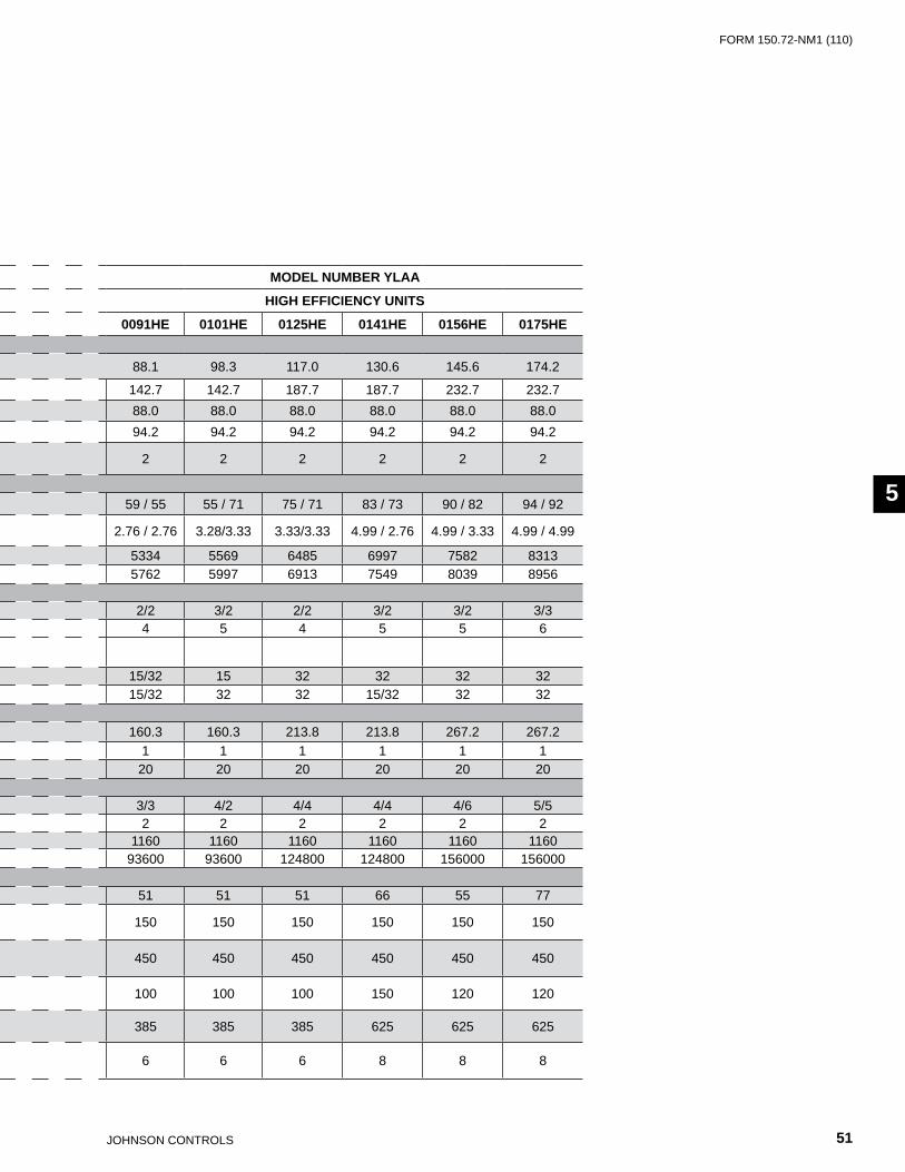
FORm 150.72-nm1 (110)
51JOHnSOn COnTROLS
55
REFRIGERANT R-410A
MODEL NUMBER YLAA MODEL NUMBER YLAA
STANDARD EFFICIENCY UNITS HIGH EFFICIENCY UNITS
0070SE 0080SE 0090SE 0100SE 0115SE 0120SE 0135SE 0150SE 0155SE 0170SE 0091HE 0101HE 0125HE 0141HE 0156HE 0175HEGENERAL UNIT DATA
Nominal Tons, R-410A 71.8 77.7 85.8 95.8 113.9 119.7 127.3 140.4 143.1 167.9 88.1 98.3 117.0 130.6 145.6 174.2
Length 116.1 116.1 116.1 142.7 142.7 142.7 187.7 187.7 187.7 232.7 142.7 142.7 187.7 187.7 232.7 232.7Width 88.0 88.0 88.0 88.0 88.0 88.0 88.0 88.0 88.0 88.0 88.0 88.0 88.0 88.0 88.0 88.0Height 94.2 94.2 94.2 94.2 94.2 94.2 94.2 94.2 94.2 94.2 94.2 94.2 94.2 94.2 94.2 94.2Number of Refrigerant Circuits 2 2 2 2 2 2 2 2 2 2 2 2 2 2 2 2
REFRIGERANT CHARGE, OPERATINGR-410A, Ckt1 / Ckt2, LBS 51 / 50 54 / 52 57 / 57 55 / 58 62 / 58 65 / 62 81 / 71 81 / 73 83 / 76 90 / 87 59 / 55 55 / 71 75 / 71 83 / 73 90 / 82 94 / 92Oil Charge, Ckt1 / Ckt2, Gallons
2.58 / 2.58
3.28 / 2.58
3.28 / 2.76
3.28 / 3.33 3.33/3.333.33/3.33 4.99 /
2.764.99 / 3.33
4.99 / 3.33 4.99 / 4.99 2.76 / 2.76 3.28/3.33 3.33/3.33 4.99 / 2.76 4.99 / 3.33 4.99 / 4.99
Shipping Weight 4112 4541 4949 5407 5644 5921 6803 6958 7152 7972 5334 5569 6485 6997 7582 8313Operating Weight 4450 4948 5435 5835 6072 6473 7260 7415 7705 8429 5762 5997 6913 7549 8039 8956
COMPRESSORS, SCROLL TYPECompressors per Circuit 3/3 3/3 3/2 3/2 2/2 3/2 3/2 3/2 3/2 3/3 2/2 3/2 2/2 3/2 3/2 3/3Compressors per Unit 6 6 5 5 4 4 5 5 5 6 4 5 4 5 5 6Nominal Tons per CompressorCircuit 1 13 15 15 15 32 32 32 32 32 32 15/32 15 32 32 32 32Circuit 2 13 13 15/32 32 32 32 15/32 32 32 32 15/32 32 32 15/32 32 32
CONDENSERTotal Face Area Ft2 106.9 106.9 106.9 133.6 160.3 160.3 213.8 213.8 213.8 267.2 160.3 160.3 213.8 213.8 267.2 267.2Number of Rows 1 1 1 1 1 1 1 1 1 1 1 1 1 1 1 1Fins per Inch 20 20 20 20 20 20 20 20 20 20 20 20 20 20 20 20
CONDENSER FANS, LOW SOUNDNumber of Fans, Ckt1./Ckt2. 2/2 2/2 2/2 3/2 3/3 3/3 4/4 4/4 4/4 5/5 3/3 4/2 4/4 4/4 4/6 5/5Fan HP 2 2 2 2 2 2 2 2 2 2 2 2 2 2 2 2Fan RPM 1160 1160 1160 1160 1160 1160 1160 1160 1160 1160 1160 1160 1160 1160 1160 1160Total Chiller CFM 62400 62400 62400 78000 93600 93600 124800 124800 124800 156000 93600 93600 124800 124800 156000 156000
EVAPORATORWater Volume, Gallons 40 49 58 51 51 66 55 55 66 55 51 51 51 66 55 77Maximum Water Side Pressure, PSIG 150 150 150 150 150 150 150 150 150 150 150 150 150 150 150 150
Maximum Refrigerant Side Pressure, PSIG 450 450 450 450 450 450 450 450 450 450 450 450 450 450 450 450
Minimum Chiller Water Flow Rate, GPM 60 100 140 100 100 150 120 120 150 120 100 100 100 150 120 120
Maximum Chiller Water Flow Rate, GPM 285 355 625 385 385 625 625 625 625 625 385 385 385 625 625 625
Water Connections Size, Inches 6 6 8 6 6 8 8 8 8 8 6 6 6 8 8 8
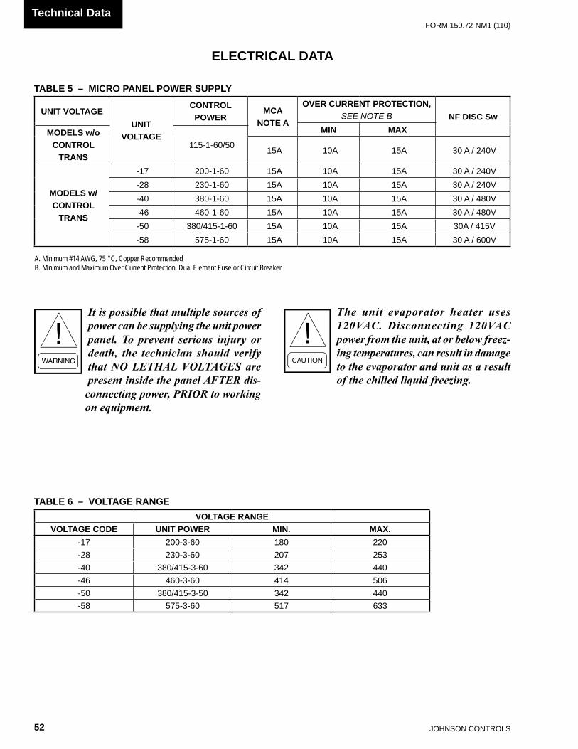
JOHnSOn COnTROLS52
FORm 150.72-nm1 (110)Technical Data
It is possible that multiple sources of power can be supplying the unit power panel. To prevent serious injury or death, the technician should verify that NO LETHAL VOLTAGES are present inside the panel AFTER dis-connecting power, PRIOR to working on equipment.
The unit evaporator heater uses 120VAC. Disconnecting 120VAC power from the unit, at or below freez-ing temperatures, can result in damage to the evaporator and unit as a result of the chilled liquid freezing.
ELECTRICAL DATA
TABLE 5 – MICRO PANEL POWER SUPPLY
VOLTAGE RANGEVOLTAGE CODE UNIT POWER MIN. MAX.
-17 200-3-60 180 220-28 230-3-60 207 253-40 380/415-3-60 342 440-46 460-3-60 414 506-50 380/415-3-50 342 440-58 575-3-60 517 633
UNIT VOLTAGEUNIT
VOLTAGE
CONTROL POWER
MCANOTE A
OVER CURRENT PROTECTION,SEE NOTE B NF DISC Sw
MIN MAXMODELS w/oCONTROL
TRANS115-1-60/50 15A 10A 15A 30 A / 240v
MODELS w/CONTROL
TRANS
-17 200-1-60 15A 10A 15A 30 A / 240v-28 230-1-60 15A 10A 15A 30 A / 240v-40 380-1-60 15A 10A 15A 30 A / 480v-46 460-1-60 15A 10A 15A 30 A / 480v-50 380/415-1-60 15A 10A 15A 30A / 415v-58 575-1-60 15A 10A 15A 30 A / 600v
A. Minimum #14 AWG, 75 °C, Copper RecommendedB. Minimum and Maximum Over Current Protection, Dual Element Fuse or Circuit Breaker
TABLE 6 – VOLTAGE RANGE

FORm 150.72-nm1 (110)
53JOHnSOn COnTROLS
55
ELECTRICAL NOTES
1. Minimum Circuit Ampacity (MCA) is based on 125% of the rated load amps for the largest motor plus 100% of the rated load amps for all other loads included in the circuit, per N.E.C. Article 430-24. If the optional Factory Mounted Control Transformer is provided, add the following MCA values to the electrical tables for the system providing power to the transformer: -17, add 2.5 amps; -28, add 2.3 amps; -40, add 1.5 amps, -46, add 1.3 amps; -58, add 1 amps.
2. The minimum recommended disconnect switch is based on 115% of the rated load amps for all loads included in the circuit, per N.E.C. Article 440.
3. Minimum fuse size is based upon 150% of the rated load amps for the largest motor plus 100% of the rated load amps for all other loads included in the circuit to avoid nuisance trips at start-up due to lock rotor amps. It is not recommended in applications where brown outs, frequent starting and stopping of the unit, and/or operation at ambient temperatures in excess of 95ºF (35ºC) is anticipated.
4. Maximum fuse size is based upon 225% of the rated load amps for the largest motor plus 100% of the rated load amps for all other loads included in the circuit, per N.E.C. Article 440-22.
5. Circuit breakers must be UL listed and CSA certi-fied and maximum size is based on 225% of the rated load amps for the largest motor plus 100% of
LEGEND ACR-LInE ACROSS THE LInE START C.B. CIRCUIT BREAKER D.E. DUAL ELEmEnT FUSE DISC SW DISCOnnECT SWITCH FACT mOUnT CB FACTORY mOUnTED CIRCUIT BREAKER FLA FULL LOAD AmPS HZ HERTZ mAX mAXImUm mCA mInImUm CIRCUIT AmPACITY mIn mInImUm mIn nF mInImUm nOn FUSED RLA RATED LOAD AmPS S.P. WIRE SInGLE POInT WIRInG UnIT mTD SERv SW UnIT mOUnTED SERvICE (nOn-FUSED DISCOnnECT SWITCH) LRA LOCKED ROTOR AmPS
-17 = 200-3-60-28 = 230-3-60-40 = 380-3-60-46 = 460-3-60-50 = 380/415-3-50-58 = 575-3-60
VOLTAGE CODE
the rated load amps for all other loads included in the circuit. Otherwise, HACR-type circuit breakers must be used. Maximum HACR circuit breaker rating is based on 225% of the rated load amps for the largest motor plus 100% of the rated load amps for all other loads included in the circuit.
6. The “INCOMING WIRE RANGE” is the minimum and maximum wire size that can be accommodated by the unit wiring lugs. The (2) preceding the wire range indicates the number of termination points available per phase of the wire range specified. Actual wire size and number of wires per phase must be determined based on the National Electri-cal Code, using copper connectors only. Field wiring must also comply with local codes.
7. A ground lug is provided for each compressor sys-tem to accommodate a field grounding conductor per N.E.C. Table 250-95. A control circuit ground-ing lug is also supplied.
8. The supplied disconnect is a “Disconnecting Means” as defined in the N.E.C. 100, and is in-tended for isolating the unit for the available power supply to perform maintenance and troubleshoot-ing. This disconnect is not intended to be a Load Break Device.
9. Field Wiring by others which complies to the Na-tional Electrical Code and Local Codes.

JOHnSOn COnTROLS54
FORm 150.72-nm1 (110)Technical Data
ELECTRICAL DATA W/O PUMPS
CHILLERMODEL VOLT HZ
MIN. CKT.
AMPS
MIN N/F DISC SW
MIN DUAL ELEM FUSE
MAX DUAL ELEM FUSE
& MAX CB
SYSTEM # 1 SYSTEM # 2COMPR 1 COMPR 2 COMPR 3 COND FANS COMPR 1 COMPR 2 COMPR 3 COND FANS
RLA LRA RLA LRA RLA LRA QTY FLA LRA RLA LRA RLA LRA RLA LRA QTY FLA LRA
YLAA0070SE
208 60 351 400 400 400 51.3 300 51.3 300 51.3 300 2 7.6 30.9 51.3 300 51.3 300 51.3 300 2 7.6 30.9230 60 350 400 400 400 51.3 300 51.3 300 51.3 300 2 7.4 37.0 51.3 300 51.3 300 51.3 300 2 7.4 37.0380 60 186 250 200 200 26.9 139 26.9 139 26.9 139 2 4.5 22.3 26.9 139 26.9 139 26.9 139 2 4.5 22.3460 60 160 200 175 175 23.1 150 23.1 150 23.1 150 2 4.0 19.0 23.1 150 23.1 150 23.1 150 2 4.0 19.0575 60 136 200 150 150 19.9 109 19.9 109 19.9 109 2 2.9 14.6 19.9 109 19.9 109 19.9 109 2 2.9 14.6
YLAA0080SE
208 60 366 600 400 400 55.8 425 55.8 425 55.8 425 2 7.6 30.9 51.3 300 51.3 300 51.3 300 2 7.6 30.9230 60 365 600 400 400 55.8 425 55.8 425 55.8 425 2 7.4 37.0 51.3 300 51.3 300 51.3 300 2 7.4 37.0380 60 216 250 225 250 36.0 239 36.0 239 36.0 239 2 4.5 22.3 26.9 139 26.9 139 26.9 139 2 4.5 22.3460 60 173 200 200 200 26.9 187 26.9 187 26.9 187 2 4.0 19.0 23.1 150 23.1 150 23.1 150 2 4.0 19.0575 60 148 200 175 175 23.7 148 23.7 148 23.7 148 2 2.9 14.6 19.9 109 19.9 109 19.9 109 2 2.9 14.6
YLAA0090SE
208 60 391 600 450 500 55.8 425 55.8 425 55.8 425 2 7.6 30.9 109.6 599 55.8 425 2 7.6 30.9230 60 390 600 450 450 55.8 425 55.8 425 55.8 425 2 7.4 37.0 109.6 599 55.8 425 2 7.4 37.0380 60 249 400 300 300 36.0 239 36.0 239 36.0 239 2 4.5 22.3 69.2 358 36.0 239 2 4.5 22.3460 60 192 250 225 225 26.9 187 26.9 187 26.9 187 2 4.0 19.0 54.5 310 26.9 187 2 4.0 19.0575 60 168 200 200 200 23.7 148 23.7 148 23.7 148 2 2.9 14.6 49.4 239 23.7 148 2 2.9 14.6
YLAA0100SE
208 60 452 600 500 500 55.8 425 55.8 425 55.8 425 2 7.6 30.9 109.6 599 110 599 3 7.6 30.9230 60 451 600 500 500 55.8 425 55.8 425 55.8 425 2 7.4 37.0 109.6 599 110 599 3 7.4 37.0380 60 286 400 350 350 36.0 239 36.0 239 36.0 239 2 4.5 22.3 69.2 358 69.2 358 3 4.5 22.3460 60 223 250 250 250 26.9 187 26.9 187 26.9 187 2 4.0 19.0 54.5 310 54.5 310 3 4.0 19.0575 60 197 250 225 225 23.7 148 23.7 148 23.7 148 2 2.9 14.6 49.4 239 49.4 239 3 2.9 14.6
YLAA0115YLAA0120
SE
208 60 511 600 600 600 109.6 599 109.6 599 3 7.6 30.9 109.6 599 109.6 599 3 7.6 30.9230 60 510 600 600 600 109.6 599 109.6 599 3 7.4 37.0 109.6 599 109.6 599 3 7.4 37.0380 60 321 400 350 350 69.2 358 69.2 358 3 4.5 22.3 69.2 358 69.2 358 3 4.5 22.3460 60 256 400 300 300 54.5 310 54.5 310 3 4.0 19.0 54.5 310 54.5 310 3 4.0 19.0575 60 227 250 250 250 49.4 239 49.4 239 3 2.9 14.6 49.4 239 49.4 239 3 2.9 14.6
YLAA0135SE
208 60 582 800 700 700 109.6 599 109.6 599 109.6 599 4 7.6 30.9 109.6 599 55.8 425 4 7.6 30.9230 60 581 800 700 700 109.6 599 109.6 599 109.6 599 4 7.4 37.0 109.6 599 55.8 425 4 7.4 37.0380 60 366 600 400 400 69.2 358 69.2 358 69.2 358 4 4.5 22.3 69.2 358 36.0 239 4 4.5 22.3460 60 291 400 350 350 54.5 310 54.5 310 54.5 310 4 4.0 19.0 54.5 310 26.9 187 4 4.0 19.0575 60 257 400 300 300 49.4 239 49.4 239 49.4 239 4 2.9 14.6 49.4 239 23.7 148 4 2.9 14.6
YLAA0150YLAA0155
SE
208 60 636 800 700 700 109.6 599 109.6 599 109.6 599 4 7.6 30.9 109.6 599 109.6 599 4 7.6 30.9230 60 635 800 700 700 109.6 599 109.6 599 109.6 599 4 7.4 37.0 109.6 599 109.6 599 4 7.4 37.0380 60 399 600 450 450 69.2 358 69.2 358 69.2 358 4 4.5 22.3 69.2 358 69.2 358 4 4.5 22.3460 60 318 400 350 350 54.5 310 54.5 310 54.5 310 4 4.0 19.0 54.5 310 54.5 310 4 4.0 19.0575 60 283 400 300 300 49.4 239 49.4 239 49.4 239 4 2.9 14.6 49.4 239 49.4 239 4 2.9 14.6
YLAA0170HE
208 60 761 1000 800 800 109.6 599 109.6 599 109.6 599 5 7.6 30.9 109.6 599 110 599 109.6 599 5 7.6 30.9230 60 759 1000 800 800 109.6 599 109.6 599 109.6 599 5 7.4 37.0 109.6 599 110 599 109.6 599 5 7.4 37.0380 60 478 600 500 500 69.2 358 69.2 358 69.2 358 5 4.5 22.3 69.2 358 69.2 358 69.2 358 5 4.5 22.3460 60 381 600 400 400 54.5 310 54.5 310 54.5 310 5 4.0 19.0 54.5 310 54.5 310 54.5 310 5 4.0 19.0575 60 338 400 400 400 49.4 239 49.4 239 49.4 239 5 2.9 14.6 49.4 239 49.4 239 49.4 239 5 2.9 14.6

FORm 150.72-nm1 (110)
55JOHnSOn COnTROLS
55
CHILLERMODEL VOLT HZ
MIN. CKT.
AMPS
MIN N/F DISC SW
MIN DUAL ELEM FUSE
MAX DUAL ELEM FUSE
& MAX CB
SYSTEM # 1 SYSTEM # 2COMPR 1 COMPR 2 COMPR 3 COND FANS COMPR 1 COMPR 2 COMPR 3 COND FANS
RLA LRA RLA LRA RLA LRA QTY FLA LRA RLA LRA RLA LRA RLA LRA QTY FLA LRA
YLAA0070SE
208 60 351 400 400 400 51.3 300 51.3 300 51.3 300 2 7.6 30.9 51.3 300 51.3 300 51.3 300 2 7.6 30.9230 60 350 400 400 400 51.3 300 51.3 300 51.3 300 2 7.4 37.0 51.3 300 51.3 300 51.3 300 2 7.4 37.0380 60 186 250 200 200 26.9 139 26.9 139 26.9 139 2 4.5 22.3 26.9 139 26.9 139 26.9 139 2 4.5 22.3460 60 160 200 175 175 23.1 150 23.1 150 23.1 150 2 4.0 19.0 23.1 150 23.1 150 23.1 150 2 4.0 19.0575 60 136 200 150 150 19.9 109 19.9 109 19.9 109 2 2.9 14.6 19.9 109 19.9 109 19.9 109 2 2.9 14.6
YLAA0080SE
208 60 366 600 400 400 55.8 425 55.8 425 55.8 425 2 7.6 30.9 51.3 300 51.3 300 51.3 300 2 7.6 30.9230 60 365 600 400 400 55.8 425 55.8 425 55.8 425 2 7.4 37.0 51.3 300 51.3 300 51.3 300 2 7.4 37.0380 60 216 250 225 250 36.0 239 36.0 239 36.0 239 2 4.5 22.3 26.9 139 26.9 139 26.9 139 2 4.5 22.3460 60 173 200 200 200 26.9 187 26.9 187 26.9 187 2 4.0 19.0 23.1 150 23.1 150 23.1 150 2 4.0 19.0575 60 148 200 175 175 23.7 148 23.7 148 23.7 148 2 2.9 14.6 19.9 109 19.9 109 19.9 109 2 2.9 14.6
YLAA0090SE
208 60 391 600 450 500 55.8 425 55.8 425 55.8 425 2 7.6 30.9 109.6 599 55.8 425 2 7.6 30.9230 60 390 600 450 450 55.8 425 55.8 425 55.8 425 2 7.4 37.0 109.6 599 55.8 425 2 7.4 37.0380 60 249 400 300 300 36.0 239 36.0 239 36.0 239 2 4.5 22.3 69.2 358 36.0 239 2 4.5 22.3460 60 192 250 225 225 26.9 187 26.9 187 26.9 187 2 4.0 19.0 54.5 310 26.9 187 2 4.0 19.0575 60 168 200 200 200 23.7 148 23.7 148 23.7 148 2 2.9 14.6 49.4 239 23.7 148 2 2.9 14.6
YLAA0100SE
208 60 452 600 500 500 55.8 425 55.8 425 55.8 425 2 7.6 30.9 109.6 599 110 599 3 7.6 30.9230 60 451 600 500 500 55.8 425 55.8 425 55.8 425 2 7.4 37.0 109.6 599 110 599 3 7.4 37.0380 60 286 400 350 350 36.0 239 36.0 239 36.0 239 2 4.5 22.3 69.2 358 69.2 358 3 4.5 22.3460 60 223 250 250 250 26.9 187 26.9 187 26.9 187 2 4.0 19.0 54.5 310 54.5 310 3 4.0 19.0575 60 197 250 225 225 23.7 148 23.7 148 23.7 148 2 2.9 14.6 49.4 239 49.4 239 3 2.9 14.6
YLAA0115YLAA0120
SE
208 60 511 600 600 600 109.6 599 109.6 599 3 7.6 30.9 109.6 599 109.6 599 3 7.6 30.9230 60 510 600 600 600 109.6 599 109.6 599 3 7.4 37.0 109.6 599 109.6 599 3 7.4 37.0380 60 321 400 350 350 69.2 358 69.2 358 3 4.5 22.3 69.2 358 69.2 358 3 4.5 22.3460 60 256 400 300 300 54.5 310 54.5 310 3 4.0 19.0 54.5 310 54.5 310 3 4.0 19.0575 60 227 250 250 250 49.4 239 49.4 239 3 2.9 14.6 49.4 239 49.4 239 3 2.9 14.6
YLAA0135SE
208 60 582 800 700 700 109.6 599 109.6 599 109.6 599 4 7.6 30.9 109.6 599 55.8 425 4 7.6 30.9230 60 581 800 700 700 109.6 599 109.6 599 109.6 599 4 7.4 37.0 109.6 599 55.8 425 4 7.4 37.0380 60 366 600 400 400 69.2 358 69.2 358 69.2 358 4 4.5 22.3 69.2 358 36.0 239 4 4.5 22.3460 60 291 400 350 350 54.5 310 54.5 310 54.5 310 4 4.0 19.0 54.5 310 26.9 187 4 4.0 19.0575 60 257 400 300 300 49.4 239 49.4 239 49.4 239 4 2.9 14.6 49.4 239 23.7 148 4 2.9 14.6
YLAA0150YLAA0155
SE
208 60 636 800 700 700 109.6 599 109.6 599 109.6 599 4 7.6 30.9 109.6 599 109.6 599 4 7.6 30.9230 60 635 800 700 700 109.6 599 109.6 599 109.6 599 4 7.4 37.0 109.6 599 109.6 599 4 7.4 37.0380 60 399 600 450 450 69.2 358 69.2 358 69.2 358 4 4.5 22.3 69.2 358 69.2 358 4 4.5 22.3460 60 318 400 350 350 54.5 310 54.5 310 54.5 310 4 4.0 19.0 54.5 310 54.5 310 4 4.0 19.0575 60 283 400 300 300 49.4 239 49.4 239 49.4 239 4 2.9 14.6 49.4 239 49.4 239 4 2.9 14.6
YLAA0170HE
208 60 761 1000 800 800 109.6 599 109.6 599 109.6 599 5 7.6 30.9 109.6 599 110 599 109.6 599 5 7.6 30.9230 60 759 1000 800 800 109.6 599 109.6 599 109.6 599 5 7.4 37.0 109.6 599 110 599 109.6 599 5 7.4 37.0380 60 478 600 500 500 69.2 358 69.2 358 69.2 358 5 4.5 22.3 69.2 358 69.2 358 69.2 358 5 4.5 22.3460 60 381 600 400 400 54.5 310 54.5 310 54.5 310 5 4.0 19.0 54.5 310 54.5 310 54.5 310 5 4.0 19.0575 60 338 400 400 400 49.4 239 49.4 239 49.4 239 5 2.9 14.6 49.4 239 49.4 239 49.4 239 5 2.9 14.6

JOHnSOn COnTROLS56
FORm 150.72-nm1 (110)Technical Data
ELECTRICAL DATA W/O PUMPS (CONT’D)
CHILLERMODEL VOLT HZ
MIN.CKT.
AMPS
MIN N/F DISC SW
MIN DUAL ELEM FUSE
MAX DUAL ELEM FUSE
& MAX CB
SYSTEM # 1 SYSTEM # 2COMPR 1 COMPR 2 COMPR 3 COND FANS COMPR 1 COMPR 2 COMPR 3 COND FANS
RLA LRA RLA LRA RLA LRA QTY FLA LRA RLA LRA RLA LRA RLA LRA QTY FLA LRA
YLAA0091 HE
208 60 404 600 450 500 109.6 599 55.8 425 3 7.6 30.9 109.6 599 55.8 425 3 7.6 30.9230 60 403 600 450 500 109.6 358 55.8 425 3 7.4 37.0 109.6 599 55.8 425 3 7.4 37.0380 60 255 400 300 300 69.2 310 36.0 239 3 4.5 22.3 69.2 358 36.0 239 3 4.5 22.3460 60 200 250 225 250 54.5 239 26.9 187 3 4.0 19.0 54.5 310 26.9 187 3 4.0 19.0575 60 176 200 200 225 49.4 310 23.7 148 3 2.9 14.6 49.4 239 23.7 148 3 2.9 14.6
YLAA0101HE
208 60 460 600 500 500 55.8 425 55.8 425 55.8 425 2 7.6 30.9 109.6 599 109.6 599 4 7.6 30.9230 60 458 600 500 500 55.8 425 55.8 425 55.8 425 2 7.4 37.0 109.6 599 109.6 599 4 7.4 37.0380 60 291 400 350 350 36.0 239 36.0 239 36.0 239 2 4.5 22.3 69.2 358 69.2 358 4 4.5 22.3460 60 227 250 250 250 26.9 187 26.9 187 26.9 187 2 4.0 19.0 54.5 310 54.5 310 4 4.0 19.0575 60 200 250 225 225 23.7 148 23.7 148 23.7 148 2 2.9 14.6 49.4 239 49.4 239 4 2.9 14.6
YLAA0125HE
208 60 527 600 600 600 109.6 599 109.6 599 4 7.6 30.9 109.6 599 110 599 4 7.6 30.9230 60 525 600 600 600 109.6 599 109.6 599 4 7.4 37.0 109.6 599 110 599 4 7.4 37.0380 60 330 400 350 350 69.2 358 69.2 358 4 4.5 22.3 69.2 358 69.2 358 4 4.5 22.3460 60 264 400 300 300 54.5 310 54.5 310 4 4.0 19.0 54.5 310 54.5 310 4 4.0 19.0575 60 233 400 250 250 49.4 239 49.4 239 4 2.9 14.6 49.4 239 49.4 239 4 2.9 14.6
YLAA0141HE
208 60 582 800 700 700 109.6 599 109.6 599 109.6 599 5 7.6 30.9 109.6 599 55.8 425 3 7.6 30.9230 60 581 800 700 700 109.6 599 109.6 599 109.6 599 5 7.4 37.0 109.6 599 55.8 425 3 7.4 37.0380 60 366 600 400 400 69.2 358 69.2 358 69.2 358 5 4.5 22.3 69.2 358 36 239 3 4.5 22.3460 60 291 400 350 350 54.5 310 54.5 310 54.5 310 5 4.0 19.0 54.5 310 26.9 187 3 4.0 19.0575 60 257 400 300 300 49.4 239 49.4 239 49.4 239 5 2.9 14.6 49.4 239 23.7 148 3 2.9 14.6
YLAA0156HE
208 60 651 800 700 700 109.6 599 109.6 599 109.6 599 6 7.6 30.9 109.6 599 109.6 599 4 7.6 30.9230 60 649 800 700 700 109.6 599 109.6 599 109.6 599 6 7.4 37.0 109.6 599 110 599 4 7.4 37.0380 60 408 600 450 450 69.2 358 69.2 358 69.2 358 6 4.5 22.3 69.2 358 69.2 358 4 4.5 22.3460 60 326 400 350 350 54.5 310 54.5 310 54.5 310 6 4.0 19.0 54.5 310 54.5 310 4 4.0 19.0575 60 288 400 350 350 49.4 239 49.4 239 49.4 239 6 2.9 14.6 49.4 239 49.4 239 4 2.9 14.6
YLAA0175HE
208 60 761 1000 800 800 109.6 599 109.6 599 109.6 599 5 7.6 30.9 109.6 599 110 599 109.6 599 5 7.6 30.9230 60 759 1000 800 800 109.6 599 109.6 599 109.6 599 5 7.4 37.0 109.6 599 110 599 109.6 599 5 7.4 37.0380 60 478 600 500 500 69.2 358 69.2 358 69.2 358 5 4.5 22.3 69.2 358 69.2 358 69.2 358 5 4.5 22.3460 60 381 600 400 400 54.5 310 54.5 310 54.5 310 5 4.0 19.0 54.5 310 54.5 310 54.5 310 5 4.0 19.0575 60 338 400 400 400 49.4 239 49.4 239 49.4 239 5 2.9 14.6 49.4 239 49.4 239 49.4 239 5 2.9 14.6

FORm 150.72-nm1 (110)
57JOHnSOn COnTROLS
55
CHILLERMODEL VOLT HZ
MIN.CKT.
AMPS
MIN N/F DISC SW
MIN DUAL ELEM FUSE
MAX DUAL ELEM FUSE
& MAX CB
SYSTEM # 1 SYSTEM # 2COMPR 1 COMPR 2 COMPR 3 COND FANS COMPR 1 COMPR 2 COMPR 3 COND FANS
RLA LRA RLA LRA RLA LRA QTY FLA LRA RLA LRA RLA LRA RLA LRA QTY FLA LRA
YLAA0091 HE
208 60 404 600 450 500 109.6 599 55.8 425 3 7.6 30.9 109.6 599 55.8 425 3 7.6 30.9230 60 403 600 450 500 109.6 358 55.8 425 3 7.4 37.0 109.6 599 55.8 425 3 7.4 37.0380 60 255 400 300 300 69.2 310 36.0 239 3 4.5 22.3 69.2 358 36.0 239 3 4.5 22.3460 60 200 250 225 250 54.5 239 26.9 187 3 4.0 19.0 54.5 310 26.9 187 3 4.0 19.0575 60 176 200 200 225 49.4 310 23.7 148 3 2.9 14.6 49.4 239 23.7 148 3 2.9 14.6
YLAA0101HE
208 60 460 600 500 500 55.8 425 55.8 425 55.8 425 2 7.6 30.9 109.6 599 109.6 599 4 7.6 30.9230 60 458 600 500 500 55.8 425 55.8 425 55.8 425 2 7.4 37.0 109.6 599 109.6 599 4 7.4 37.0380 60 291 400 350 350 36.0 239 36.0 239 36.0 239 2 4.5 22.3 69.2 358 69.2 358 4 4.5 22.3460 60 227 250 250 250 26.9 187 26.9 187 26.9 187 2 4.0 19.0 54.5 310 54.5 310 4 4.0 19.0575 60 200 250 225 225 23.7 148 23.7 148 23.7 148 2 2.9 14.6 49.4 239 49.4 239 4 2.9 14.6
YLAA0125HE
208 60 527 600 600 600 109.6 599 109.6 599 4 7.6 30.9 109.6 599 110 599 4 7.6 30.9230 60 525 600 600 600 109.6 599 109.6 599 4 7.4 37.0 109.6 599 110 599 4 7.4 37.0380 60 330 400 350 350 69.2 358 69.2 358 4 4.5 22.3 69.2 358 69.2 358 4 4.5 22.3460 60 264 400 300 300 54.5 310 54.5 310 4 4.0 19.0 54.5 310 54.5 310 4 4.0 19.0575 60 233 400 250 250 49.4 239 49.4 239 4 2.9 14.6 49.4 239 49.4 239 4 2.9 14.6
YLAA0141HE
208 60 582 800 700 700 109.6 599 109.6 599 109.6 599 5 7.6 30.9 109.6 599 55.8 425 3 7.6 30.9230 60 581 800 700 700 109.6 599 109.6 599 109.6 599 5 7.4 37.0 109.6 599 55.8 425 3 7.4 37.0380 60 366 600 400 400 69.2 358 69.2 358 69.2 358 5 4.5 22.3 69.2 358 36 239 3 4.5 22.3460 60 291 400 350 350 54.5 310 54.5 310 54.5 310 5 4.0 19.0 54.5 310 26.9 187 3 4.0 19.0575 60 257 400 300 300 49.4 239 49.4 239 49.4 239 5 2.9 14.6 49.4 239 23.7 148 3 2.9 14.6
YLAA0156HE
208 60 651 800 700 700 109.6 599 109.6 599 109.6 599 6 7.6 30.9 109.6 599 109.6 599 4 7.6 30.9230 60 649 800 700 700 109.6 599 109.6 599 109.6 599 6 7.4 37.0 109.6 599 110 599 4 7.4 37.0380 60 408 600 450 450 69.2 358 69.2 358 69.2 358 6 4.5 22.3 69.2 358 69.2 358 4 4.5 22.3460 60 326 400 350 350 54.5 310 54.5 310 54.5 310 6 4.0 19.0 54.5 310 54.5 310 4 4.0 19.0575 60 288 400 350 350 49.4 239 49.4 239 49.4 239 6 2.9 14.6 49.4 239 49.4 239 4 2.9 14.6
YLAA0175HE
208 60 761 1000 800 800 109.6 599 109.6 599 109.6 599 5 7.6 30.9 109.6 599 110 599 109.6 599 5 7.6 30.9230 60 759 1000 800 800 109.6 599 109.6 599 109.6 599 5 7.4 37.0 109.6 599 110 599 109.6 599 5 7.4 37.0380 60 478 600 500 500 69.2 358 69.2 358 69.2 358 5 4.5 22.3 69.2 358 69.2 358 69.2 358 5 4.5 22.3460 60 381 600 400 400 54.5 310 54.5 310 54.5 310 5 4.0 19.0 54.5 310 54.5 310 54.5 310 5 4.0 19.0575 60 338 400 400 400 49.4 239 49.4 239 49.4 239 5 2.9 14.6 49.4 239 49.4 239 49.4 239 5 2.9 14.6
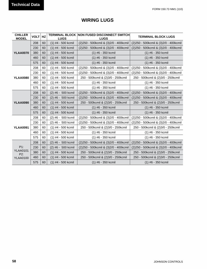
JOHnSOn COnTROLS58
FORm 150.72-nm1 (110)Technical Data
CHILLER MODEL VOLT HZ TERMINAL BLOCK
LUGSNON FUSED DISCONNECT SWITCH
LUGS TERMINAL BLOCK LUGS
YLAA0070
208 60 (1) #4 - 500 kcmil (2)250 - 500kcmil & (3)2/0 - 400kcmil (2)250 - 500kcmil & (3)2/0 - 400kcmil230 60 (1) #4 - 500 kcmil (2)250 - 500kcmil & (3)2/0 - 400kcmil (2)250 - 500kcmil & (3)2/0 - 400kcmil380 60 (1) #4 - 500 kcmil (1) #6 - 350 kcmil (1) #6 - 350 kcmil460 60 (1) #4 - 500 kcmil (1) #6 - 350 kcmil (1) #6 - 350 kcmil575 60 (1) #4 - 500 kcmil (1) #6 - 350 kcmil (1) #6 - 350 kcmil
YLAA0080
208 60 (1) #4 - 500 kcmil (2)250 - 500kcmil & (3)2/0 - 400kcmil (2)250 - 500kcmil & (3)2/0 - 400kcmil230 60 (1) #4 - 500 kcmil (2)250 - 500kcmil & (3)2/0 - 400kcmil (2)250 - 500kcmil & (3)2/0 - 400kcmil380 60 (1) #4 - 500 kcmil 250 - 500kcmil & (2)3/0 - 250kcmil 250 - 500kcmil & (2)3/0 - 250kcmil460 60 (1) #4 - 500 kcmil (1) #6 - 350 kcmil (1) #6 - 350 kcmil575 60 (1) #4 - 500 kcmil (1) #6 - 350 kcmil (1) #6 - 350 kcmil
YLAA0090
208 60 (2) #6 - 500 kcmil (2)250 - 500kcmil & (3)2/0 - 400kcmil (2)250 - 500kcmil & (3)2/0 - 400kcmil230 60 (2) #6 - 500 kcmil (2)250 - 500kcmil & (3)2/0 - 400kcmil (2)250 - 500kcmil & (3)2/0 - 400kcmil380 60 (1) #4 - 500 kcmil 250 - 500kcmil & (2)3/0 - 250kcmil 250 - 500kcmil & (2)3/0 - 250kcmil460 60 (1) #4 - 500 kcmil (1) #6 - 350 kcmil (1) #6 - 350 kcmil575 60 (1) #4 - 500 kcmil (1) #6 - 350 kcmil (1) #6 - 350 kcmil
YLAA0091
208 60 (2) #6 - 500 kcmil (2)250 - 500kcmil & (3)2/0 - 400kcmil (2)250 - 500kcmil & (3)2/0 - 400kcmil230 60 (2) #6 - 500 kcmil (2)250 - 500kcmil & (3)2/0 - 400kcmil (2)250 - 500kcmil & (3)2/0 - 400kcmil380 60 (1) #4 - 500 kcmil 250 - 500kcmil & (2)3/0 - 250kcmil 250 - 500kcmil & (2)3/0 - 250kcmil460 60 (1) #4 - 500 kcmil (1) #6 - 350 kcmil (1) #6 - 350 kcmil575 60 (1) #4 - 500 kcmil (1) #6 - 350 kcmil (1) #6 - 350 kcmil
P1: YLAA0101
P2: YLAA0100
208 60 (2) #6 - 500 kcmil (2)250 - 500kcmil & (3)2/0 - 400kcmil (2)250 - 500kcmil & (3)2/0 - 400kcmil230 60 (2) #6 - 500 kcmil (2)250 - 500kcmil & (3)2/0 - 400kcmil (2)250 - 500kcmil & (3)2/0 - 400kcmil380 60 (1) #4 - 500 kcmil 250 - 500kcmil & (2)3/0 - 250kcmil 250 - 500kcmil & (2)3/0 - 250kcmil460 60 (1) #4 - 500 kcmil 250 - 500kcmil & (2)3/0 - 250kcmil 250 - 500kcmil & (2)3/0 - 250kcmil575 60 (1) #4 - 500 kcmil (1) #6 - 350 kcmil (1) #6 - 350 kcmil
WIRING LUGS

FORm 150.72-nm1 (110)
59JOHnSOn COnTROLS
55
CHILLER MODEL VOLT HZ TERMINAL BLOCK
LUGSNON FUSED DISCONNECT SWITCH
LUGS TERMINAL BLOCK LUGS
P1: YLAA0115 & YLAA0120
P2: YLAA0125
208 60 (2) #6 - 500 kcmil (2)250 - 500kcmil & (3)2/0 - 400kcmil (2)250 - 500kcmil & (3)2/0 - 400kcmil230 60 (2) #6 - 500 kcmil (2)250 - 500kcmil & (3)2/0 - 400kcmil (2)250 - 500kcmil & (3)2/0 - 400kcmil380 60 (1) #4 - 500 kcmil 250 - 500kcmil & (2)3/0 - 250kcmil 250 - 500kcmil & (2)3/0 - 250kcmil460 60 (1) #4 - 500 kcmil 250 - 500kcmil & (2)3/0 - 250kcmil 250 - 500kcmil & (2)3/0 - 250kcmil575 60 (1) #4 - 500 kcmil 250 - 500kcmil & (2)3/0 - 250kcmil 250 - 500kcmil & (2)3/0 - 250kcmil
P1: YLAA0135
P2: YLAA0141
208 60 (2) #6 - 500 kcmil (2)250 - 500kcmil & (3)2/0 - 400kcmil (2)250 - 500kcmil & (3)2/0 - 400kcmil230 60 (2) #6 - 500 kcmil (2)250 - 500kcmil & (3)2/0 - 400kcmil (2)250 - 500kcmil & (3)2/0 - 400kcmil380 60 (1) #4 - 500 kcmil (2)250 - 500kcmil & (3)2/0 - 400kcmil 250 - 500kcmil & (2)3/0 - 250kcmil460 60 (1) #4 - 500 kcmil 250 - 500kcmil & (2)3/0 - 250kcmil 250 - 500kcmil & (2)3/0 - 250kcmil575 60 (1) #4 - 500 kcmil 250 - 500kcmil & (2)3/0 - 250kcmil 250 - 500kcmil & (2)3/0 - 250kcmil
P1: YLAA0150 & YLAA0155
P2: YLAA0156
208 60 (2) #6 - 500 kcmil (2)250 - 500kcmil & (3)2/0 - 400kcmil (2)250 - 500kcmil & (3)2/0 - 400kcmil230 60 (2) #6 - 500 kcmil (2)250 - 500kcmil & (3)2/0 - 400kcmil (2)250 - 500kcmil & (3)2/0 - 400kcmil380 60 (2) #6 - 500 kcmil (2)250 - 500kcmil & (3)2/0 - 400kcmil (2)250 - 500kcmil & (3)2/0 - 400kcmil460 60 (1) #4 - 500 kcmil 250 - 500kcmil & (2)3/0 - 250kcmil 250 - 500kcmil & (2)3/0 - 250kcmil575 60 (1) #4 - 500 kcmil 250 - 500kcmil & (2)3/0 - 250kcmil 250 - 500kcmil & (2)3/0 - 250kcmil
P2: YLAA0170 & YLAA0175
208 60 (2) #6 - 500 kcmil (4) 4/0 - 500kcmil (2)250 - 500kcmil & (3)2/0 - 400kcmil230 60 (2) #6 - 500 kcmil (4) 4/0 - 500kcmil (2)250 - 500kcmil & (3)2/0 - 400kcmil380 60 (2) #6 - 500 kcmil (2)250 - 500kcmil & (3)2/0 - 400kcmil (2)250 - 500kcmil & (3)2/0 - 400kcmil460 60 (2) #6 - 500 kcmil (2)250 - 500kcmil & (3)2/0 - 400kcmil (2)250 - 500kcmil & (3)2/0 - 400kcmil575 60 (1) #4 - 500 kcmil (2)250 - 500kcmil & (3)2/0 - 400kcmil 250 - 500kcmil & (2)3/0 - 250kcmil
WIRING LUGS (CONT’D)
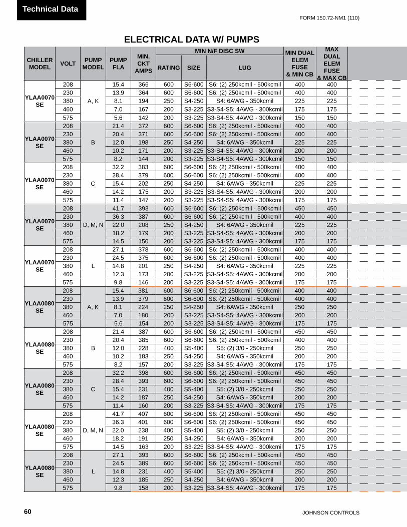
JOHnSOn COnTROLS60
FORm 150.72-nm1 (110)Technical Data
ELECTRICAL DATA W/ PUMPS
CHILLERMODEL VOLT PUMP
MODELPUMPFLA
MIN.CKT
AMPS
MIN N/F DISC SW MIN DUALELEM FUSE
& MIN CB
MAX DUALELEM FUSE
& MAX CB
SYSTEM # 1 SYSTEM # 2
RATING SIZE LUGCOMPR 1 COMPR 2 COMPR 3 COND FANS COMPR 1 COMPR 2 COMPR 3 COND FANS
RLA LRA RLA LRA RLA LRA QTY FLA LRA RLA LRA RLA LRA RLA LRA QTY FLA LRA
YLAA0070SE
208
A, K
15.4 366 600 S6-600 S6: (2) 250kcmil - 500kcmil 400 400 51.3 300 51.3 300 51.3 300 2 7.6 30.9 51.3 300 51.3 300 51.3 300 2 7.6 30.9230 13.9 364 600 S6-600 S6: (2) 250kcmil - 500kcmil 400 400 51.3 300 51.3 300 51.3 300 2 7.4 37.0 51.3 300 51.3 300 51.3 300 2 7.4 37.0380 8.1 194 250 S4-250 S4: 6AWG - 350kcmil 225 225 26.9 139 26.9 139 26.9 139 2 4.5 22.3 26.9 139 26.9 139 26.9 139 2 4.5 22.3460 7.0 167 200 S3-225 S3-S4-S5: 4AWG - 300kcmil 175 175 23.1 150 23.1 150 23.1 150 2 4.0 19.0 23.1 150 23.1 150 23.1 150 2 4.0 19.0575 5.6 142 200 S3-225 S3-S4-S5: 4AWG - 300kcmil 150 150 19.9 109 19.9 109 19.9 109 2 2.9 14.6 19.9 109 19.9 109 19.9 109 2 2.9 14.6
YLAA0070SE
208
B
21.4 372 600 S6-600 S6: (2) 250kcmil - 500kcmil 400 400 51.3 300 51.3 300 51.3 300 2 7.6 30.9 51.3 300 51.3 300 51.3 300 2 7.6 30.9230 20.4 371 600 S6-600 S6: (2) 250kcmil - 500kcmil 400 400 51.3 300 51.3 300 51.3 300 2 7.4 37.0 51.3 300 51.3 300 51.3 300 2 7.4 37.0380 12.0 198 250 S4-250 S4: 6AWG - 350kcmil 225 225 26.9 139 26.9 139 26.9 139 2 4.5 22.3 26.9 139 26.9 139 26.9 139 2 4.5 22.3460 10.2 171 200 S3-225 S3-S4-S5: 4AWG - 300kcmil 200 200 23.1 150 23.1 150 23.1 150 2 4.0 19.0 23.1 150 23.1 150 23.1 150 2 4.0 19.0575 8.2 144 200 S3-225 S3-S4-S5: 4AWG - 300kcmil 150 150 19.9 109 19.9 109 19.9 109 2 2.9 14.6 19.9 109 19.9 109 19.9 109 2 2.9 14.6
YLAA0070SE
208
C
32.2 383 600 S6-600 S6: (2) 250kcmil - 500kcmil 400 400 51.3 300 51.3 300 51.3 300 2 7.6 30.9 51.3 300 51.3 300 51.3 300 2 7.6 30.9230 28.4 379 600 S6-600 S6: (2) 250kcmil - 500kcmil 400 400 51.3 300 51.3 300 51.3 300 2 7.4 37.0 51.3 300 51.3 300 51.3 300 2 7.4 37.0380 15.4 202 250 S4-250 S4: 6AWG - 350kcmil 225 225 26.9 139 26.9 139 26.9 139 2 4.5 22.3 26.9 139 26.9 139 26.9 139 2 4.5 22.3460 14.2 175 200 S3-225 S3-S4-S5: 4AWG - 300kcmil 200 200 23.1 150 23.1 150 23.1 150 2 4.0 19.0 23.1 150 23.1 150 23.1 150 2 4.0 19.0575 11.4 147 200 S3-225 S3-S4-S5: 4AWG - 300kcmil 175 175 19.9 109 19.9 109 19.9 109 2 2.9 14.6 19.9 109 19.9 109 19.9 109 2 2.9 14.6
YLAA0070SE
208
D, m, n
41.7 393 600 S6-600 S6: (2) 250kcmil - 500kcmil 450 450 51.3 300 51.3 300 51.3 300 2 7.6 30.9 51.3 300 51.3 300 51.3 300 2 7.6 30.9230 36.3 387 600 S6-600 S6: (2) 250kcmil - 500kcmil 400 400 51.3 300 51.3 300 51.3 300 2 7.4 37.0 51.3 300 51.3 300 51.3 300 2 7.4 37.0380 22.0 208 250 S4-250 S4: 6AWG - 350kcmil 225 225 26.9 139 26.9 139 26.9 139 2 4.5 22.3 26.9 139 26.9 139 26.9 139 2 4.5 22.3460 18.2 179 200 S3-225 S3-S4-S5: 4AWG - 300kcmil 200 200 23.1 150 23.1 150 23.1 150 2 4.0 19.0 23.1 150 23.1 150 23.1 150 2 4.0 19.0575 14.5 150 200 S3-225 S3-S4-S5: 4AWG - 300kcmil 175 175 19.9 109 19.9 109 19.9 109 2 2.9 14.6 19.9 109 19.9 109 19.9 109 2 2.9 14.6
YLAA0070SE
208
L
27.1 378 600 S6-600 S6: (2) 250kcmil - 500kcmil 400 400 51.3 300 51.3 300 51.3 300 2 7.6 30.9 51.3 300 51.3 300 51.3 300 2 7.6 30.9230 24.5 375 600 S6-600 S6: (2) 250kcmil - 500kcmil 400 400 51.3 300 51.3 300 51.3 300 2 7.4 37.0 51.3 300 51.3 300 51.3 300 2 7.4 37.0380 14.8 201 250 S4-250 S4: 6AWG - 350kcmil 225 225 26.9 139 26.9 139 26.9 139 2 4.5 22.3 26.9 139 26.9 139 26.9 139 2 4.5 22.3460 12.3 173 200 S3-225 S3-S4-S5: 4AWG - 300kcmil 200 200 23.1 150 23.1 150 23.1 150 2 4.0 19.0 23.1 150 23.1 150 23.1 150 2 4.0 19.0575 9.8 146 200 S3-225 S3-S4-S5: 4AWG - 300kcmil 175 175 19.9 109 19.9 109 19.9 109 2 2.9 14.6 19.9 109 19.9 109 19.9 109 2 2.9 14.6
YLAA0080SE
208
A, K
15.4 381 600 S6-600 S6: (2) 250kcmil - 500kcmil 400 400 55.8 425 55.8 425 55.8 425 2 7.6 30.9 51.3 300 51.3 300 51.3 300 2 7.6 30.9230 13.9 379 600 S6-600 S6: (2) 250kcmil - 500kcmil 400 400 55.8 425 55.8 425 55.8 425 2 7.4 37.0 51.3 300 51.3 300 51.3 300 2 7.4 37.0380 8.1 224 250 S4-250 S4: 6AWG - 350kcmil 250 250 36.0 239 36.0 239 36.0 239 2 4.5 22.3 26.9 139 26.9 139 26.9 139 2 4.5 22.3460 7.0 180 200 S3-225 S3-S4-S5: 4AWG - 300kcmil 200 200 26.9 187 26.9 187 26.9 187 2 4.0 19.0 23.1 150 23.1 150 23.1 150 2 4.0 19.0575 5.6 154 200 S3-225 S3-S4-S5: 4AWG - 300kcmil 175 175 23.7 148 23.7 148 23.7 148 2 2.9 14.6 19.9 109 19.9 109 19.9 109 2 2.9 14.6
YLAA0080SE
208
B
21.4 387 600 S6-600 S6: (2) 250kcmil - 500kcmil 450 450 55.8 425 55.8 425 55.8 425 2 7.6 30.9 51.3 300 51.3 300 51.3 300 2 7.6 30.9230 20.4 385 600 S6-600 S6: (2) 250kcmil - 500kcmil 400 400 55.8 425 55.8 425 55.8 425 2 7.4 37.0 51.3 300 51.3 300 51.3 300 2 7.4 37.0380 12.0 228 400 S5-400 S5: (2) 3/0 - 250kcmil 250 250 36.0 239 36.0 239 36.0 239 2 4.5 22.3 26.9 139 26.9 139 26.9 139 2 4.5 22.3460 10.2 183 250 S4-250 S4: 6AWG - 350kcmil 200 200 26.9 187 26.9 187 26.9 187 2 4.0 19.0 23.1 150 23.1 150 23.1 150 2 4.0 19.0575 8.2 157 200 S3-225 S3-S4-S5: 4AWG - 300kcmil 175 175 23.7 148 23.7 148 23.7 148 2 2.9 14.6 19.9 109 19.9 109 19.9 109 2 2.9 14.6
YLAA0080SE
208
C
32.2 398 600 S6-600 S6: (2) 250kcmil - 500kcmil 450 450 55.8 425 55.8 425 55.8 425 2 7.6 30.9 51.3 300 51.3 300 51.3 300 2 7.6 30.9230 28.4 393 600 S6-600 S6: (2) 250kcmil - 500kcmil 450 450 55.8 425 55.8 425 55.8 425 2 7.4 37.0 51.3 300 51.3 300 51.3 300 2 7.4 37.0380 15.4 231 400 S5-400 S5: (2) 3/0 - 250kcmil 250 250 36.0 239 36.0 239 36.0 239 2 4.5 22.3 26.9 139 26.9 139 26.9 139 2 4.5 22.3460 14.2 187 250 S4-250 S4: 6AWG - 350kcmil 200 200 26.9 187 26.9 187 26.9 187 2 4.0 19.0 23.1 150 23.1 150 23.1 150 2 4.0 19.0575 11.4 160 200 S3-225 S3-S4-S5: 4AWG - 300kcmil 175 175 23.7 148 23.7 148 23.7 148 2 2.9 14.6 19.9 109 19.9 109 19.9 109 2 2.9 14.6
YLAA0080SE
208
D, m, n
41.7 407 600 S6-600 S6: (2) 250kcmil - 500kcmil 450 450 55.8 425 55.8 425 55.8 425 2 7.6 30.9 51.3 300 51.3 300 51.3 300 2 7.6 30.9230 36.3 401 600 S6-600 S6: (2) 250kcmil - 500kcmil 450 450 55.8 425 55.8 425 55.8 425 2 7.4 37.0 51.3 300 51.3 300 51.3 300 2 7.4 37.0380 22.0 238 400 S5-400 S5: (2) 3/0 - 250kcmil 250 250 36.0 239 36.0 239 36.0 239 2 4.5 22.3 26.9 139 26.9 139 26.9 139 2 4.5 22.3460 18.2 191 250 S4-250 S4: 6AWG - 350kcmil 200 200 26.9 187 26.9 187 26.9 187 2 4.0 19.0 23.1 150 23.1 150 23.1 150 2 4.0 19.0575 14.5 163 200 S3-225 S3-S4-S5: 4AWG - 300kcmil 175 175 23.7 148 23.7 148 23.7 148 2 2.9 14.6 19.9 109 19.9 109 19.9 109 2 2.9 14.6
YLAA0080SE
208
L
27.1 393 600 S6-600 S6: (2) 250kcmil - 500kcmil 450 450 55.8 425 55.8 425 55.8 425 2 7.6 30.9 51.3 300 51.3 300 51.3 300 2 7.6 30.9230 24.5 389 600 S6-600 S6: (2) 250kcmil - 500kcmil 450 450 55.8 425 55.8 425 55.8 425 2 7.4 37.0 51.3 300 51.3 300 51.3 300 2 7.4 37.0380 14.8 231 400 S5-400 S5: (2) 3/0 - 250kcmil 250 250 36.0 239 36.0 239 36.0 239 2 4.5 22.3 26.9 139 26.9 139 26.9 139 2 4.5 22.3460 12.3 185 250 S4-250 S4: 6AWG - 350kcmil 200 200 26.9 187 26.9 187 26.9 187 2 4.0 19.0 23.1 150 23.1 150 23.1 150 2 4.0 19.0575 9.8 158 200 S3-225 S3-S4-S5: 4AWG - 300kcmil 175 175 23.7 148 23.7 148 23.7 148 2 2.9 14.6 19.9 109 19.9 109 19.9 109 2 2.9 14.6

FORm 150.72-nm1 (110)
61JOHnSOn COnTROLS
55
CHILLERMODEL VOLT PUMP
MODELPUMPFLA
MIN.CKT
AMPS
MIN N/F DISC SW MIN DUALELEM FUSE
& MIN CB
MAX DUALELEM FUSE
& MAX CB
SYSTEM # 1 SYSTEM # 2
RATING SIZE LUGCOMPR 1 COMPR 2 COMPR 3 COND FANS COMPR 1 COMPR 2 COMPR 3 COND FANS
RLA LRA RLA LRA RLA LRA QTY FLA LRA RLA LRA RLA LRA RLA LRA QTY FLA LRA
YLAA0070SE
208
A, K
15.4 366 600 S6-600 S6: (2) 250kcmil - 500kcmil 400 400 51.3 300 51.3 300 51.3 300 2 7.6 30.9 51.3 300 51.3 300 51.3 300 2 7.6 30.9230 13.9 364 600 S6-600 S6: (2) 250kcmil - 500kcmil 400 400 51.3 300 51.3 300 51.3 300 2 7.4 37.0 51.3 300 51.3 300 51.3 300 2 7.4 37.0380 8.1 194 250 S4-250 S4: 6AWG - 350kcmil 225 225 26.9 139 26.9 139 26.9 139 2 4.5 22.3 26.9 139 26.9 139 26.9 139 2 4.5 22.3460 7.0 167 200 S3-225 S3-S4-S5: 4AWG - 300kcmil 175 175 23.1 150 23.1 150 23.1 150 2 4.0 19.0 23.1 150 23.1 150 23.1 150 2 4.0 19.0575 5.6 142 200 S3-225 S3-S4-S5: 4AWG - 300kcmil 150 150 19.9 109 19.9 109 19.9 109 2 2.9 14.6 19.9 109 19.9 109 19.9 109 2 2.9 14.6
YLAA0070SE
208
B
21.4 372 600 S6-600 S6: (2) 250kcmil - 500kcmil 400 400 51.3 300 51.3 300 51.3 300 2 7.6 30.9 51.3 300 51.3 300 51.3 300 2 7.6 30.9230 20.4 371 600 S6-600 S6: (2) 250kcmil - 500kcmil 400 400 51.3 300 51.3 300 51.3 300 2 7.4 37.0 51.3 300 51.3 300 51.3 300 2 7.4 37.0380 12.0 198 250 S4-250 S4: 6AWG - 350kcmil 225 225 26.9 139 26.9 139 26.9 139 2 4.5 22.3 26.9 139 26.9 139 26.9 139 2 4.5 22.3460 10.2 171 200 S3-225 S3-S4-S5: 4AWG - 300kcmil 200 200 23.1 150 23.1 150 23.1 150 2 4.0 19.0 23.1 150 23.1 150 23.1 150 2 4.0 19.0575 8.2 144 200 S3-225 S3-S4-S5: 4AWG - 300kcmil 150 150 19.9 109 19.9 109 19.9 109 2 2.9 14.6 19.9 109 19.9 109 19.9 109 2 2.9 14.6
YLAA0070SE
208
C
32.2 383 600 S6-600 S6: (2) 250kcmil - 500kcmil 400 400 51.3 300 51.3 300 51.3 300 2 7.6 30.9 51.3 300 51.3 300 51.3 300 2 7.6 30.9230 28.4 379 600 S6-600 S6: (2) 250kcmil - 500kcmil 400 400 51.3 300 51.3 300 51.3 300 2 7.4 37.0 51.3 300 51.3 300 51.3 300 2 7.4 37.0380 15.4 202 250 S4-250 S4: 6AWG - 350kcmil 225 225 26.9 139 26.9 139 26.9 139 2 4.5 22.3 26.9 139 26.9 139 26.9 139 2 4.5 22.3460 14.2 175 200 S3-225 S3-S4-S5: 4AWG - 300kcmil 200 200 23.1 150 23.1 150 23.1 150 2 4.0 19.0 23.1 150 23.1 150 23.1 150 2 4.0 19.0575 11.4 147 200 S3-225 S3-S4-S5: 4AWG - 300kcmil 175 175 19.9 109 19.9 109 19.9 109 2 2.9 14.6 19.9 109 19.9 109 19.9 109 2 2.9 14.6
YLAA0070SE
208
D, m, n
41.7 393 600 S6-600 S6: (2) 250kcmil - 500kcmil 450 450 51.3 300 51.3 300 51.3 300 2 7.6 30.9 51.3 300 51.3 300 51.3 300 2 7.6 30.9230 36.3 387 600 S6-600 S6: (2) 250kcmil - 500kcmil 400 400 51.3 300 51.3 300 51.3 300 2 7.4 37.0 51.3 300 51.3 300 51.3 300 2 7.4 37.0380 22.0 208 250 S4-250 S4: 6AWG - 350kcmil 225 225 26.9 139 26.9 139 26.9 139 2 4.5 22.3 26.9 139 26.9 139 26.9 139 2 4.5 22.3460 18.2 179 200 S3-225 S3-S4-S5: 4AWG - 300kcmil 200 200 23.1 150 23.1 150 23.1 150 2 4.0 19.0 23.1 150 23.1 150 23.1 150 2 4.0 19.0575 14.5 150 200 S3-225 S3-S4-S5: 4AWG - 300kcmil 175 175 19.9 109 19.9 109 19.9 109 2 2.9 14.6 19.9 109 19.9 109 19.9 109 2 2.9 14.6
YLAA0070SE
208
L
27.1 378 600 S6-600 S6: (2) 250kcmil - 500kcmil 400 400 51.3 300 51.3 300 51.3 300 2 7.6 30.9 51.3 300 51.3 300 51.3 300 2 7.6 30.9230 24.5 375 600 S6-600 S6: (2) 250kcmil - 500kcmil 400 400 51.3 300 51.3 300 51.3 300 2 7.4 37.0 51.3 300 51.3 300 51.3 300 2 7.4 37.0380 14.8 201 250 S4-250 S4: 6AWG - 350kcmil 225 225 26.9 139 26.9 139 26.9 139 2 4.5 22.3 26.9 139 26.9 139 26.9 139 2 4.5 22.3460 12.3 173 200 S3-225 S3-S4-S5: 4AWG - 300kcmil 200 200 23.1 150 23.1 150 23.1 150 2 4.0 19.0 23.1 150 23.1 150 23.1 150 2 4.0 19.0575 9.8 146 200 S3-225 S3-S4-S5: 4AWG - 300kcmil 175 175 19.9 109 19.9 109 19.9 109 2 2.9 14.6 19.9 109 19.9 109 19.9 109 2 2.9 14.6
YLAA0080SE
208
A, K
15.4 381 600 S6-600 S6: (2) 250kcmil - 500kcmil 400 400 55.8 425 55.8 425 55.8 425 2 7.6 30.9 51.3 300 51.3 300 51.3 300 2 7.6 30.9230 13.9 379 600 S6-600 S6: (2) 250kcmil - 500kcmil 400 400 55.8 425 55.8 425 55.8 425 2 7.4 37.0 51.3 300 51.3 300 51.3 300 2 7.4 37.0380 8.1 224 250 S4-250 S4: 6AWG - 350kcmil 250 250 36.0 239 36.0 239 36.0 239 2 4.5 22.3 26.9 139 26.9 139 26.9 139 2 4.5 22.3460 7.0 180 200 S3-225 S3-S4-S5: 4AWG - 300kcmil 200 200 26.9 187 26.9 187 26.9 187 2 4.0 19.0 23.1 150 23.1 150 23.1 150 2 4.0 19.0575 5.6 154 200 S3-225 S3-S4-S5: 4AWG - 300kcmil 175 175 23.7 148 23.7 148 23.7 148 2 2.9 14.6 19.9 109 19.9 109 19.9 109 2 2.9 14.6
YLAA0080SE
208
B
21.4 387 600 S6-600 S6: (2) 250kcmil - 500kcmil 450 450 55.8 425 55.8 425 55.8 425 2 7.6 30.9 51.3 300 51.3 300 51.3 300 2 7.6 30.9230 20.4 385 600 S6-600 S6: (2) 250kcmil - 500kcmil 400 400 55.8 425 55.8 425 55.8 425 2 7.4 37.0 51.3 300 51.3 300 51.3 300 2 7.4 37.0380 12.0 228 400 S5-400 S5: (2) 3/0 - 250kcmil 250 250 36.0 239 36.0 239 36.0 239 2 4.5 22.3 26.9 139 26.9 139 26.9 139 2 4.5 22.3460 10.2 183 250 S4-250 S4: 6AWG - 350kcmil 200 200 26.9 187 26.9 187 26.9 187 2 4.0 19.0 23.1 150 23.1 150 23.1 150 2 4.0 19.0575 8.2 157 200 S3-225 S3-S4-S5: 4AWG - 300kcmil 175 175 23.7 148 23.7 148 23.7 148 2 2.9 14.6 19.9 109 19.9 109 19.9 109 2 2.9 14.6
YLAA0080SE
208
C
32.2 398 600 S6-600 S6: (2) 250kcmil - 500kcmil 450 450 55.8 425 55.8 425 55.8 425 2 7.6 30.9 51.3 300 51.3 300 51.3 300 2 7.6 30.9230 28.4 393 600 S6-600 S6: (2) 250kcmil - 500kcmil 450 450 55.8 425 55.8 425 55.8 425 2 7.4 37.0 51.3 300 51.3 300 51.3 300 2 7.4 37.0380 15.4 231 400 S5-400 S5: (2) 3/0 - 250kcmil 250 250 36.0 239 36.0 239 36.0 239 2 4.5 22.3 26.9 139 26.9 139 26.9 139 2 4.5 22.3460 14.2 187 250 S4-250 S4: 6AWG - 350kcmil 200 200 26.9 187 26.9 187 26.9 187 2 4.0 19.0 23.1 150 23.1 150 23.1 150 2 4.0 19.0575 11.4 160 200 S3-225 S3-S4-S5: 4AWG - 300kcmil 175 175 23.7 148 23.7 148 23.7 148 2 2.9 14.6 19.9 109 19.9 109 19.9 109 2 2.9 14.6
YLAA0080SE
208
D, m, n
41.7 407 600 S6-600 S6: (2) 250kcmil - 500kcmil 450 450 55.8 425 55.8 425 55.8 425 2 7.6 30.9 51.3 300 51.3 300 51.3 300 2 7.6 30.9230 36.3 401 600 S6-600 S6: (2) 250kcmil - 500kcmil 450 450 55.8 425 55.8 425 55.8 425 2 7.4 37.0 51.3 300 51.3 300 51.3 300 2 7.4 37.0380 22.0 238 400 S5-400 S5: (2) 3/0 - 250kcmil 250 250 36.0 239 36.0 239 36.0 239 2 4.5 22.3 26.9 139 26.9 139 26.9 139 2 4.5 22.3460 18.2 191 250 S4-250 S4: 6AWG - 350kcmil 200 200 26.9 187 26.9 187 26.9 187 2 4.0 19.0 23.1 150 23.1 150 23.1 150 2 4.0 19.0575 14.5 163 200 S3-225 S3-S4-S5: 4AWG - 300kcmil 175 175 23.7 148 23.7 148 23.7 148 2 2.9 14.6 19.9 109 19.9 109 19.9 109 2 2.9 14.6
YLAA0080SE
208
L
27.1 393 600 S6-600 S6: (2) 250kcmil - 500kcmil 450 450 55.8 425 55.8 425 55.8 425 2 7.6 30.9 51.3 300 51.3 300 51.3 300 2 7.6 30.9230 24.5 389 600 S6-600 S6: (2) 250kcmil - 500kcmil 450 450 55.8 425 55.8 425 55.8 425 2 7.4 37.0 51.3 300 51.3 300 51.3 300 2 7.4 37.0380 14.8 231 400 S5-400 S5: (2) 3/0 - 250kcmil 250 250 36.0 239 36.0 239 36.0 239 2 4.5 22.3 26.9 139 26.9 139 26.9 139 2 4.5 22.3460 12.3 185 250 S4-250 S4: 6AWG - 350kcmil 200 200 26.9 187 26.9 187 26.9 187 2 4.0 19.0 23.1 150 23.1 150 23.1 150 2 4.0 19.0575 9.8 158 200 S3-225 S3-S4-S5: 4AWG - 300kcmil 175 175 23.7 148 23.7 148 23.7 148 2 2.9 14.6 19.9 109 19.9 109 19.9 109 2 2.9 14.6

JOHnSOn COnTROLS62
FORm 150.72-nm1 (110)Technical Data
ELECTRICAL DATA W/ PUMPS (CONT’D)
CHILLERMODEL VOLT PUMP
MODELPUMPFLA
MIN.CKT
AMPS
MIN N/F DISC SW MIN DUALELEM FUSE
& MIN CB
MAX DUALELEM FUSE
& MAX CB
SYSTEM # 1 SYSTEM # 2
RATING SIZE LUGCOMPR 1 COMPR 2 COMPR 3 COND FANS COMPR 1 COMPR 2 COMPR 3 COND FANS
RLA LRA RLA LRA RLA LRA QTY FLA LRA RLA LRA RLA LRA RLA LRA QTY FLA LRA
YLAA0090SE
208
A, K
15.4 406 600 S6-600 S6: (2) 250kcmil - 500kcmil 450 500 55.8 425 55.8 425 55.8 425 2 7.6 30.9 109.6 599 55.8 425 2 7.6 30.9230 13.9 404 600 S6-600 S6: (2) 250kcmil - 500kcmil 450 500 55.8 425 55.8 425 55.8 425 2 7.4 37.0 109.6 599 55.8 425 2 7.4 37.0380 8.1 257 400 S5-400 S5: (2) 3/0 - 250kcmil 300 300 36.0 239 36.0 239 36.0 239 2 4.5 22.3 69.2 358 36.0 239 2 4.5 22.3460 7.0 199 250 S4-250 S4: 6AWG - 350kcmil 225 250 26.9 187 26.9 187 26.9 187 2 4.0 19.0 54.5 310 26.9 187 2 4.0 19.0575 5.6 174 200 S3-225 S3-S4-S5: 4AWG - 300kcmil 200 200 23.7 148 23.7 148 23.7 148 2 2.9 14.6 49.4 239 23.7 148 2 2.9 14.6
YLAA0090SE
208
B
21.4 412 600 S6-600 S6: (2) 250kcmil - 500kcmil 450 500 55.8 425 55.8 425 55.8 425 2 7.6 30.9 109.6 599 55.8 425 2 7.6 30.9230 20.4 410 600 S6-600 S6: (2) 250kcmil - 500kcmil 450 500 55.8 425 55.8 425 55.8 425 2 7.4 37.0 109.6 599 55.8 425 2 7.4 37.0380 12.0 261 400 S5-400 S5: (2) 3/0 - 250kcmil 300 300 36.0 239 36.0 239 36.0 239 2 4.5 22.3 69.2 358 36.0 239 2 4.5 22.3460 10.2 202 250 S4-250 S4: 6AWG - 350kcmil 225 250 26.9 187 26.9 187 26.9 187 2 4.0 19.0 54.5 310 26.9 187 2 4.0 19.0575 8.2 176 200 S3-225 S3-S4-S5: 4AWG - 300kcmil 200 225 23.7 148 23.7 148 23.7 148 2 2.9 14.6 49.4 239 23.7 148 2 2.9 14.6
YLAA0090SE
208
D, m, n
41.7 432 600 S6-600 S6: (2) 250kcmil - 500kcmil 500 500 55.8 425 55.8 425 55.8 425 2 7.6 30.9 109.6 599 55.8 425 2 7.6 30.9230 36.3 426 600 S6-600 S6: (2) 250kcmil - 500kcmil 500 500 55.8 425 55.8 425 55.8 425 2 7.4 37.0 109.6 599 55.8 425 2 7.4 37.0380 22.0 271 400 S5-400 S5: (2) 3/0 - 250kcmil 300 300 36.0 239 36.0 239 36.0 239 2 4.5 22.3 69.2 358 36.0 239 2 4.5 22.3460 18.2 210 250 S4-250 S4: 6AWG - 350kcmil 225 250 26.9 187 26.9 187 26.9 187 2 4.0 19.0 54.5 310 26.9 187 2 4.0 19.0575 14.5 183 200 S3-225 S3-S4-S5: 4AWG - 300kcmil 200 225 23.7 148 23.7 148 23.7 148 2 2.9 14.6 49.4 239 23.7 148 2 2.9 14.6
YLAA0090SE
208
E
54.7 445 600 S6-600 S6: (2) 250kcmil - 500kcmil 500 500 55.8 425 55.8 425 55.8 425 2 7.6 30.9 109.6 599 55.8 425 2 7.6 30.9230 49.5 439 600 S6-600 S6: (2) 250kcmil - 500kcmil 500 500 55.8 425 55.8 425 55.8 425 2 7.4 37.0 109.6 599 55.8 425 2 7.4 37.0380 29.1 278 400 S5-400 S5: (2) 3/0 - 250kcmil 300 300 36.0 239 36.0 239 36.0 239 2 4.5 22.3 69.2 358 36.0 239 2 4.5 22.3460 24.8 217 250 S4-250 S4: 6AWG - 350kcmil 250 250 26.9 187 26.9 187 26.9 187 2 4.0 19.0 54.5 310 26.9 187 2 4.0 19.0575 19.8 188 250 S4-250 S4: 6AWG - 350kcmil 225 225 23.7 148 23.7 148 23.7 148 2 2.9 14.6 49.4 239 23.7 148 2 2.9 14.6
YLAA0090SE
208
L
27.1 418 600 S6-600 S6: (2) 250kcmil - 500kcmil 450 500 55.8 425 55.8 425 55.8 425 2 7.6 30.9 109.6 599 55.8 425 2 7.6 30.9230 24.5 414 600 S6-600 S6: (2) 250kcmil - 500kcmil 450 500 55.8 425 55.8 425 55.8 425 2 7.4 37.0 109.6 599 55.8 425 2 7.4 37.0380 14.8 263 400 S5-400 S5: (2) 3/0 - 250kcmil 300 300 36.0 239 36.0 239 36.0 239 2 4.5 22.3 69.2 358 36.0 239 2 4.5 22.3460 12.3 204 250 S4-250 S4: 6AWG - 350kcmil 225 250 26.9 187 26.9 187 26.9 187 2 4.0 19.0 54.5 310 26.9 187 2 4.0 19.0575 9.8 178 200 S3-225 S3-S4-S5: 4AWG - 300kcmil 200 225 23.7 148 23.7 148 23.7 148 2 2.9 14.6 49.4 239 23.7 148 2 2.9 14.6
YLAA0091 HE
208
A, K
15.4 419 600 S6-600 S6: (2) 250kcmil - 500kcmil 450 500 109.6 599 55.8 425 3 7.6 30.9 109.6 599 55.8 425 3 7.6 30.9230 13.9 417 600 S6-600 S6: (2) 250kcmil - 500kcmil 450 500 109.6 358 55.8 425 3 7.4 37.0 109.6 599 55.8 425 3 7.4 37.0380 8.1 263 400 S5-400 S5: (2) 3/0 - 250kcmil 300 300 69.2 310 36.0 239 3 4.5 22.3 69.2 358 36.0 239 3 4.5 22.3460 7.0 207 250 S4-250 S4: 6AWG - 350kcmil 225 250 54.5 239 26.9 187 3 4.0 19.0 54.5 310 26.9 187 3 4.0 19.0575 5.6 182 200 S3-225 S3-S4-S5: 4AWG - 300kcmil 200 225 49.4 310 23.7 148 3 2.9 14.6 49.4 239 23.7 148 3 2.9 14.6
YLAA0091 HE
208
B
21.4 425 600 S6-600 S6: (2) 250kcmil - 500kcmil 500 500 109.6 599 55.8 425 3 7.6 30.9 109.6 599 55.8 425 3 7.6 30.9230 20.4 423 600 S6-600 S6: (2) 250kcmil - 500kcmil 500 500 109.6 358 55.8 425 3 7.4 37.0 109.6 599 55.8 425 3 7.4 37.0380 12.0 267 400 S5-400 S5: (2) 3/0 - 250kcmil 300 300 69.2 310 36.0 239 3 4.5 22.3 69.2 358 36.0 239 3 4.5 22.3460 10.2 211 250 S4-250 S4: 6AWG - 350kcmil 225 250 54.5 239 26.9 187 3 4.0 19.0 54.5 310 26.9 187 3 4.0 19.0575 8.2 184 200 S3-225 S3-S4-S5: 4AWG - 300kcmil 200 225 49.4 310 23.7 148 3 2.9 14.6 49.4 239 23.7 148 3 2.9 14.6
YLAA0091 HE
208
D, m, n
41.7 446 600 S6-600 S6: (2) 250kcmil - 500kcmil 500 500 109.6 599 55.8 425 3 7.6 30.9 109.6 599 55.8 425 3 7.6 30.9230 36.3 439 600 S6-600 S6: (2) 250kcmil - 500kcmil 500 500 109.6 358 55.8 239 3 7.4 37.0 109.6 599 55.8 425 3 7.4 37.0380 22.0 277 400 S5-400 S5: (2) 3/0 - 250kcmil 300 300 69.2 310 36.0 187 3 4.5 22.3 69.2 358 36.0 239 3 4.5 22.3460 18.2 219 250 S4-250 S4: 6AWG - 350kcmil 250 250 54.5 239 26.9 148 3 4.0 19.0 54.5 310 26.9 187 3 4.0 19.0575 14.5 190 250 S4-250 S4: 6AWG - 350kcmil 225 225 49.4 310 23.7 425 3 2.9 14.6 49.4 239 23.7 148 3 2.9 14.6
YLAA0091 HE
208
E
54.7 459 600 S6-600 S6: (2) 250kcmil - 500kcmil 500 500 109.6 599 55.8 425 3 7.6 30.9 109.6 599 55.8 425 3 7.6 30.9230 49.5 452 600 S6-600 S6: (2) 250kcmil - 500kcmil 500 500 109.6 358 55.8 425 3 7.4 37.0 109.6 599 55.8 425 3 7.4 37.0380 29.1 284 400 S5-400 S5: (2) 3/0 - 250kcmil 350 350 69.2 310 36.0 239 3 4.5 22.3 69.2 358 36.0 239 3 4.5 22.3460 24.8 225 250 S4-250 S4: 6AWG - 350kcmil 250 250 54.5 239 26.9 187 3 4.0 19.0 54.5 310 26.9 187 3 4.0 19.0575 19.8 196 250 S4-250 S4: 6AWG - 350kcmil 225 225 49.4 310 23.7 148 3 2.9 14.6 49.4 239 23.7 148 3 2.9 14.6
YLAA0091 HE
208
L
27.1 431 600 S6-600 S6: (2) 250kcmil - 500kcmil 500 500 109.6 599 55.8 425 3 7.6 30.9 109.6 599 55.8 425 3 7.6 30.9230 24.5 427 600 S6-600 S6: (2) 250kcmil - 500kcmil 500 500 109.6 358 55.8 425 3 7.4 37.0 109.6 599 55.8 425 3 7.4 37.0380 14.8 270 400 S5-400 S5: (2) 3/0 - 250kcmil 300 300 69.2 310 36.0 239 3 4.5 22.3 69.2 358 36.0 239 3 4.5 22.3460 12.3 213 250 S4-250 S4: 6AWG - 350kcmil 250 250 54.5 239 26.9 187 3 4.0 19.0 54.5 310 26.9 187 3 4.0 19.0575 9.8 186 200 S3-225 S3-S4-S5: 4AWG - 300kcmil 200 225 49.4 310 23.7 148 3 2.9 14.6 49.4 239 23.7 148 3 2.9 14.6
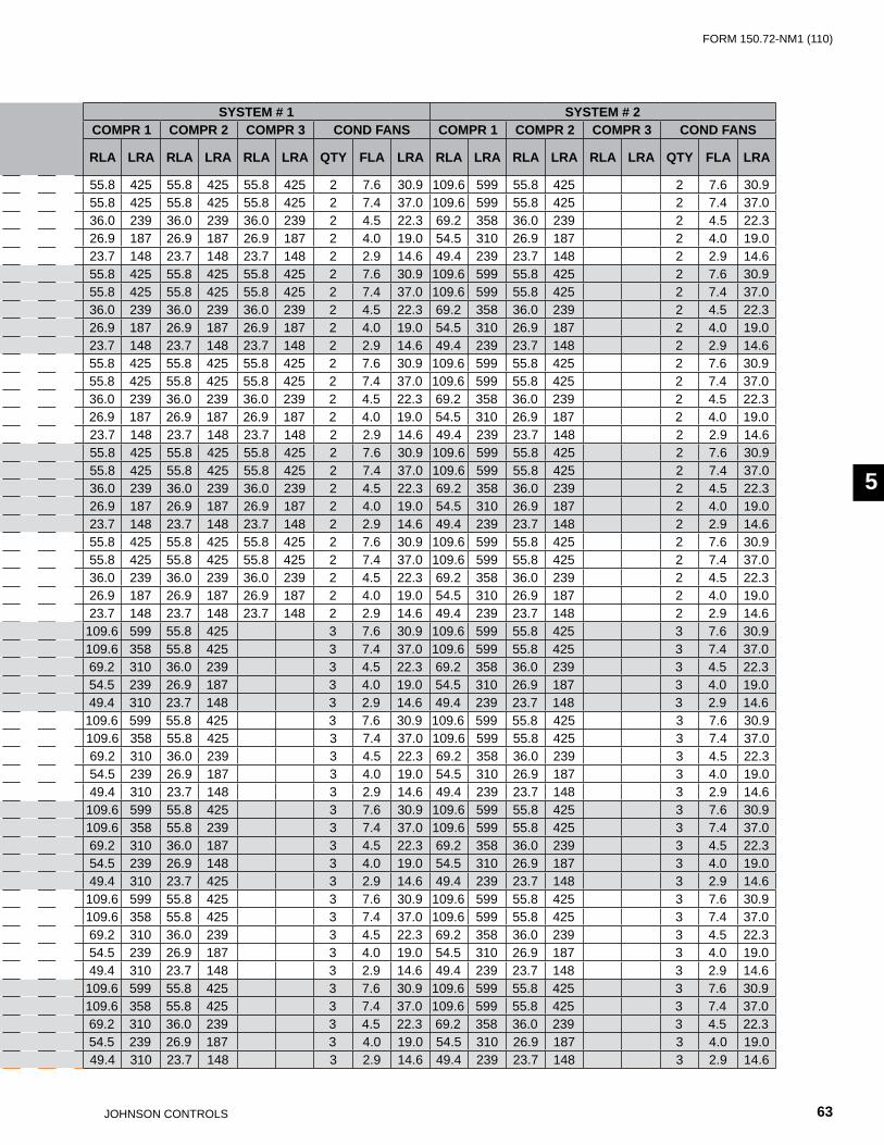
FORm 150.72-nm1 (110)
63JOHnSOn COnTROLS
55
CHILLERMODEL VOLT PUMP
MODELPUMPFLA
MIN.CKT
AMPS
MIN N/F DISC SW MIN DUALELEM FUSE
& MIN CB
MAX DUALELEM FUSE
& MAX CB
SYSTEM # 1 SYSTEM # 2
RATING SIZE LUGCOMPR 1 COMPR 2 COMPR 3 COND FANS COMPR 1 COMPR 2 COMPR 3 COND FANS
RLA LRA RLA LRA RLA LRA QTY FLA LRA RLA LRA RLA LRA RLA LRA QTY FLA LRA
YLAA0090SE
208
A, K
15.4 406 600 S6-600 S6: (2) 250kcmil - 500kcmil 450 500 55.8 425 55.8 425 55.8 425 2 7.6 30.9 109.6 599 55.8 425 2 7.6 30.9230 13.9 404 600 S6-600 S6: (2) 250kcmil - 500kcmil 450 500 55.8 425 55.8 425 55.8 425 2 7.4 37.0 109.6 599 55.8 425 2 7.4 37.0380 8.1 257 400 S5-400 S5: (2) 3/0 - 250kcmil 300 300 36.0 239 36.0 239 36.0 239 2 4.5 22.3 69.2 358 36.0 239 2 4.5 22.3460 7.0 199 250 S4-250 S4: 6AWG - 350kcmil 225 250 26.9 187 26.9 187 26.9 187 2 4.0 19.0 54.5 310 26.9 187 2 4.0 19.0575 5.6 174 200 S3-225 S3-S4-S5: 4AWG - 300kcmil 200 200 23.7 148 23.7 148 23.7 148 2 2.9 14.6 49.4 239 23.7 148 2 2.9 14.6
YLAA0090SE
208
B
21.4 412 600 S6-600 S6: (2) 250kcmil - 500kcmil 450 500 55.8 425 55.8 425 55.8 425 2 7.6 30.9 109.6 599 55.8 425 2 7.6 30.9230 20.4 410 600 S6-600 S6: (2) 250kcmil - 500kcmil 450 500 55.8 425 55.8 425 55.8 425 2 7.4 37.0 109.6 599 55.8 425 2 7.4 37.0380 12.0 261 400 S5-400 S5: (2) 3/0 - 250kcmil 300 300 36.0 239 36.0 239 36.0 239 2 4.5 22.3 69.2 358 36.0 239 2 4.5 22.3460 10.2 202 250 S4-250 S4: 6AWG - 350kcmil 225 250 26.9 187 26.9 187 26.9 187 2 4.0 19.0 54.5 310 26.9 187 2 4.0 19.0575 8.2 176 200 S3-225 S3-S4-S5: 4AWG - 300kcmil 200 225 23.7 148 23.7 148 23.7 148 2 2.9 14.6 49.4 239 23.7 148 2 2.9 14.6
YLAA0090SE
208
D, m, n
41.7 432 600 S6-600 S6: (2) 250kcmil - 500kcmil 500 500 55.8 425 55.8 425 55.8 425 2 7.6 30.9 109.6 599 55.8 425 2 7.6 30.9230 36.3 426 600 S6-600 S6: (2) 250kcmil - 500kcmil 500 500 55.8 425 55.8 425 55.8 425 2 7.4 37.0 109.6 599 55.8 425 2 7.4 37.0380 22.0 271 400 S5-400 S5: (2) 3/0 - 250kcmil 300 300 36.0 239 36.0 239 36.0 239 2 4.5 22.3 69.2 358 36.0 239 2 4.5 22.3460 18.2 210 250 S4-250 S4: 6AWG - 350kcmil 225 250 26.9 187 26.9 187 26.9 187 2 4.0 19.0 54.5 310 26.9 187 2 4.0 19.0575 14.5 183 200 S3-225 S3-S4-S5: 4AWG - 300kcmil 200 225 23.7 148 23.7 148 23.7 148 2 2.9 14.6 49.4 239 23.7 148 2 2.9 14.6
YLAA0090SE
208
E
54.7 445 600 S6-600 S6: (2) 250kcmil - 500kcmil 500 500 55.8 425 55.8 425 55.8 425 2 7.6 30.9 109.6 599 55.8 425 2 7.6 30.9230 49.5 439 600 S6-600 S6: (2) 250kcmil - 500kcmil 500 500 55.8 425 55.8 425 55.8 425 2 7.4 37.0 109.6 599 55.8 425 2 7.4 37.0380 29.1 278 400 S5-400 S5: (2) 3/0 - 250kcmil 300 300 36.0 239 36.0 239 36.0 239 2 4.5 22.3 69.2 358 36.0 239 2 4.5 22.3460 24.8 217 250 S4-250 S4: 6AWG - 350kcmil 250 250 26.9 187 26.9 187 26.9 187 2 4.0 19.0 54.5 310 26.9 187 2 4.0 19.0575 19.8 188 250 S4-250 S4: 6AWG - 350kcmil 225 225 23.7 148 23.7 148 23.7 148 2 2.9 14.6 49.4 239 23.7 148 2 2.9 14.6
YLAA0090SE
208
L
27.1 418 600 S6-600 S6: (2) 250kcmil - 500kcmil 450 500 55.8 425 55.8 425 55.8 425 2 7.6 30.9 109.6 599 55.8 425 2 7.6 30.9230 24.5 414 600 S6-600 S6: (2) 250kcmil - 500kcmil 450 500 55.8 425 55.8 425 55.8 425 2 7.4 37.0 109.6 599 55.8 425 2 7.4 37.0380 14.8 263 400 S5-400 S5: (2) 3/0 - 250kcmil 300 300 36.0 239 36.0 239 36.0 239 2 4.5 22.3 69.2 358 36.0 239 2 4.5 22.3460 12.3 204 250 S4-250 S4: 6AWG - 350kcmil 225 250 26.9 187 26.9 187 26.9 187 2 4.0 19.0 54.5 310 26.9 187 2 4.0 19.0575 9.8 178 200 S3-225 S3-S4-S5: 4AWG - 300kcmil 200 225 23.7 148 23.7 148 23.7 148 2 2.9 14.6 49.4 239 23.7 148 2 2.9 14.6
YLAA0091 HE
208
A, K
15.4 419 600 S6-600 S6: (2) 250kcmil - 500kcmil 450 500 109.6 599 55.8 425 3 7.6 30.9 109.6 599 55.8 425 3 7.6 30.9230 13.9 417 600 S6-600 S6: (2) 250kcmil - 500kcmil 450 500 109.6 358 55.8 425 3 7.4 37.0 109.6 599 55.8 425 3 7.4 37.0380 8.1 263 400 S5-400 S5: (2) 3/0 - 250kcmil 300 300 69.2 310 36.0 239 3 4.5 22.3 69.2 358 36.0 239 3 4.5 22.3460 7.0 207 250 S4-250 S4: 6AWG - 350kcmil 225 250 54.5 239 26.9 187 3 4.0 19.0 54.5 310 26.9 187 3 4.0 19.0575 5.6 182 200 S3-225 S3-S4-S5: 4AWG - 300kcmil 200 225 49.4 310 23.7 148 3 2.9 14.6 49.4 239 23.7 148 3 2.9 14.6
YLAA0091 HE
208
B
21.4 425 600 S6-600 S6: (2) 250kcmil - 500kcmil 500 500 109.6 599 55.8 425 3 7.6 30.9 109.6 599 55.8 425 3 7.6 30.9230 20.4 423 600 S6-600 S6: (2) 250kcmil - 500kcmil 500 500 109.6 358 55.8 425 3 7.4 37.0 109.6 599 55.8 425 3 7.4 37.0380 12.0 267 400 S5-400 S5: (2) 3/0 - 250kcmil 300 300 69.2 310 36.0 239 3 4.5 22.3 69.2 358 36.0 239 3 4.5 22.3460 10.2 211 250 S4-250 S4: 6AWG - 350kcmil 225 250 54.5 239 26.9 187 3 4.0 19.0 54.5 310 26.9 187 3 4.0 19.0575 8.2 184 200 S3-225 S3-S4-S5: 4AWG - 300kcmil 200 225 49.4 310 23.7 148 3 2.9 14.6 49.4 239 23.7 148 3 2.9 14.6
YLAA0091 HE
208
D, m, n
41.7 446 600 S6-600 S6: (2) 250kcmil - 500kcmil 500 500 109.6 599 55.8 425 3 7.6 30.9 109.6 599 55.8 425 3 7.6 30.9230 36.3 439 600 S6-600 S6: (2) 250kcmil - 500kcmil 500 500 109.6 358 55.8 239 3 7.4 37.0 109.6 599 55.8 425 3 7.4 37.0380 22.0 277 400 S5-400 S5: (2) 3/0 - 250kcmil 300 300 69.2 310 36.0 187 3 4.5 22.3 69.2 358 36.0 239 3 4.5 22.3460 18.2 219 250 S4-250 S4: 6AWG - 350kcmil 250 250 54.5 239 26.9 148 3 4.0 19.0 54.5 310 26.9 187 3 4.0 19.0575 14.5 190 250 S4-250 S4: 6AWG - 350kcmil 225 225 49.4 310 23.7 425 3 2.9 14.6 49.4 239 23.7 148 3 2.9 14.6
YLAA0091 HE
208
E
54.7 459 600 S6-600 S6: (2) 250kcmil - 500kcmil 500 500 109.6 599 55.8 425 3 7.6 30.9 109.6 599 55.8 425 3 7.6 30.9230 49.5 452 600 S6-600 S6: (2) 250kcmil - 500kcmil 500 500 109.6 358 55.8 425 3 7.4 37.0 109.6 599 55.8 425 3 7.4 37.0380 29.1 284 400 S5-400 S5: (2) 3/0 - 250kcmil 350 350 69.2 310 36.0 239 3 4.5 22.3 69.2 358 36.0 239 3 4.5 22.3460 24.8 225 250 S4-250 S4: 6AWG - 350kcmil 250 250 54.5 239 26.9 187 3 4.0 19.0 54.5 310 26.9 187 3 4.0 19.0575 19.8 196 250 S4-250 S4: 6AWG - 350kcmil 225 225 49.4 310 23.7 148 3 2.9 14.6 49.4 239 23.7 148 3 2.9 14.6
YLAA0091 HE
208
L
27.1 431 600 S6-600 S6: (2) 250kcmil - 500kcmil 500 500 109.6 599 55.8 425 3 7.6 30.9 109.6 599 55.8 425 3 7.6 30.9230 24.5 427 600 S6-600 S6: (2) 250kcmil - 500kcmil 500 500 109.6 358 55.8 425 3 7.4 37.0 109.6 599 55.8 425 3 7.4 37.0380 14.8 270 400 S5-400 S5: (2) 3/0 - 250kcmil 300 300 69.2 310 36.0 239 3 4.5 22.3 69.2 358 36.0 239 3 4.5 22.3460 12.3 213 250 S4-250 S4: 6AWG - 350kcmil 250 250 54.5 239 26.9 187 3 4.0 19.0 54.5 310 26.9 187 3 4.0 19.0575 9.8 186 200 S3-225 S3-S4-S5: 4AWG - 300kcmil 200 225 49.4 310 23.7 148 3 2.9 14.6 49.4 239 23.7 148 3 2.9 14.6

JOHnSOn COnTROLS64
FORm 150.72-nm1 (110)Technical Data
ELECTRICAL DATA W/ PUMPS (CONT’D)
CHILLERMODEL VOLT PUMP
MODELPUMPFLA
MIN.CKT
AMPS
MIN N/F DISC SW MIN DUALELEM FUSE
& MIN CB
MAX DUALELEM FUSE
& MAX CB
SYSTEM # 1 SYSTEM # 2
RATING SIZE LUGCOMPR 1 COMPR 2 COMPR 3 COND FANS COMPR 1 COMPR 2 COMPR 3 COND FANS
RLA LRA RLA LRA RLA LRA QTY FLA LRA RLA LRA RLA LRA RLA LRA QTY FLA LRA
YLAA0101HE
208
B, F
21.4 481 600 S6-600 S6: (2) 250kcmil - 500kcmil 600 600 55.8 425 55.8 425 55.8 425 2 7.6 30.9 109.6 599 109.6 599 4 7.6 30.9230 20.4 479 600 S6-600 S6: (2) 250kcmil - 500kcmil 600 600 55.8 425 55.8 425 55.8 425 2 7.4 37.0 109.6 599 109.6 599 4 7.4 37.0380 12.0 303 400 S5-400 S5: (2) 3/0 - 250kcmil 350 350 36.0 239 36.0 239 36.0 239 2 4.5 22.3 69.2 358 69.2 358 4 4.5 22.3460 10.2 238 400 S5-400 S5: (2) 3/0 - 250kcmil 300 300 26.9 187 26.9 187 26.9 187 2 4.0 19.0 54.5 310 54.5 310 4 4.0 19.0575 8.2 208 250 S4-250 S4: 6AWG - 350kcmil 225 250 23.7 148 23.7 148 23.7 148 2 2.9 14.6 49.4 239 49.4 239 4 2.9 14.6
YLAA0101HE
208
D, O
41.7 501 600 S6-600 S6: (2) 250kcmil - 500kcmil 600 600 55.8 425 55.8 425 55.8 425 2 7.6 30.9 109.6 599 109.6 599 4 7.6 30.9230 36.3 495 600 S6-600 S6: (2) 250kcmil - 500kcmil 600 600 55.8 425 55.8 425 55.8 425 2 7.4 37.0 109.6 599 109.6 599 4 7.4 37.0380 22.0 313 400 S5-400 S5: (2) 3/0 - 250kcmil 350 350 36.0 239 36.0 239 36.0 239 2 4.5 22.3 69.2 358 69.2 358 4 4.5 22.3460 18.2 246 400 S5-400 S5: (2) 3/0 - 250kcmil 300 300 26.9 187 26.9 187 26.9 187 2 4.0 19.0 54.5 310 54.5 310 4 4.0 19.0575 14.5 214 250 S4-250 S4: 6AWG - 350kcmil 250 250 23.7 148 23.7 148 23.7 148 2 2.9 14.6 49.4 239 49.4 239 4 2.9 14.6
YLAA0101HE
208
E, P
54.7 514 600 S6-600 S6: (2) 250kcmil - 500kcmil 600 600 55.8 425 55.8 425 55.8 425 2 7.6 30.9 109.6 599 109.6 599 4 7.6 30.9230 49.5 508 600 S6-600 S6: (2) 250kcmil - 500kcmil 600 600 55.8 425 55.8 425 55.8 425 2 7.4 37.0 109.6 599 109.6 599 4 7.4 37.0380 29.1 320 400 S5-400 S5: (2) 3/0 - 250kcmil 350 350 36.0 239 36.0 239 36.0 239 2 4.5 22.3 69.2 358 69.2 358 4 4.5 22.3460 24.8 252 400 S5-400 S5: (2) 3/0 - 250kcmil 300 300 26.9 187 26.9 187 26.9 187 2 4.0 19.0 54.5 310 54.5 310 4 4.0 19.0575 19.8 219 250 S4-250 S4: 6AWG - 350kcmil 250 250 23.7 148 23.7 148 23.7 148 2 2.9 14.6 49.4 239 49.4 239 4 2.9 14.6
YLAA0101HE
208
K
15.4 475 600 S6-600 S6: (2) 250kcmil - 500kcmil 600 600 55.8 425 55.8 425 55.8 425 2 7.6 30.9 109.6 599 109.6 599 4 7.6 30.9230 13.9 472 600 S6-600 S6: (2) 250kcmil - 500kcmil 500 500 55.8 425 55.8 425 55.8 425 2 7.4 37.0 109.6 599 109.6 599 4 7.4 37.0380 8.1 299 400 S5-400 S5: (2) 3/0 - 250kcmil 350 350 36.0 239 36.0 239 36.0 239 2 4.5 22.3 69.2 358 69.2 358 4 4.5 22.3460 7.0 234 400 S5-400 S5: (2) 3/0 - 250kcmil 250 250 26.9 187 26.9 187 26.9 187 2 4.0 19.0 54.5 310 54.5 310 4 4.0 19.0575 5.6 205 250 S4-250 S4: 6AWG - 350kcmil 225 250 23.7 148 23.7 148 23.7 148 2 2.9 14.6 49.4 239 49.4 239 4 2.9 14.6
YLAA0101HE
208
L
27.1 487 600 S6-600 S6: (2) 250kcmil - 500kcmil 600 600 55.8 425 55.8 425 55.8 425 2 7.6 30.9 109.6 599 109.6 599 4 7.6 30.9230 24.5 483 600 S6-600 S6: (2) 250kcmil - 500kcmil 600 600 55.8 425 55.8 425 55.8 425 2 7.4 37.0 109.6 599 109.6 599 4 7.4 37.0380 14.8 306 400 S5-400 S5: (2) 3/0 - 250kcmil 350 350 36.0 239 36.0 239 36.0 239 2 4.5 22.3 69.2 358 69.2 358 4 4.5 22.3460 12.3 240 400 S5-400 S5: (2) 3/0 - 250kcmil 300 300 26.9 187 26.9 187 26.9 187 2 4.0 19.0 54.5 310 54.5 310 4 4.0 19.0575 9.8 209 250 S4-250 S4: 6AWG - 350kcmil 225 250 23.7 148 23.7 148 23.7 148 2 2.9 14.6 49.4 239 49.4 239 4 2.9 14.6
YLAA0115YLAA0120
SE
208
F
21.4 533 600 S6-600 S6: (2) 250kcmil - 500kcmil 600 600 109.6 599 109.6 599 3 7.6 30.9 109.6 599 109.6 599 3 7.6 30.9230 20.4 531 600 S6-600 S6: (2) 250kcmil - 500kcmil 600 600 109.6 599 109.6 599 3 7.4 37.0 109.6 599 109.6 599 3 7.4 37.0380 12.0 333 400 S5-400 S5: (2) 3/0 - 250kcmil 400 400 69.2 358 69.2 358 3 4.5 22.3 69.2 358 69.2 358 3 4.5 22.3460 10.2 266 400 S5-400 S5: (2) 3/0 - 250kcmil 300 300 54.5 310 54.5 310 3 4.0 19.0 54.5 310 54.5 310 3 4.0 19.0575 8.2 236 400 S5-400 S5: (2) 3/0 - 250kcmil 250 250 49.4 239 49.4 239 3 2.9 14.6 49.4 239 49.4 239 3 2.9 14.6
YLAA0115YLAA0120
SE
208
C
32.2 544 600 S6-600 S6: (2) 250kcmil - 500kcmil 600 600 109.6 599 109.6 599 3 7.6 30.9 109.6 599 109.6 599 3 7.6 30.9230 28.4 539 600 S6-600 S6: (2) 250kcmil - 500kcmil 600 600 109.6 599 109.6 599 3 7.4 37.0 109.6 599 109.6 599 3 7.4 37.0380 15.4 337 400 S5-400 S5: (2) 3/0 - 250kcmil 400 400 69.2 358 69.2 358 3 4.5 22.3 69.2 358 69.2 358 3 4.5 22.3460 14.2 270 400 S5-400 S5: (2) 3/0 - 250kcmil 300 300 54.5 310 54.5 310 3 4.0 19.0 54.5 310 54.5 310 3 4.0 19.0575 11.4 239 400 S5-400 S5: (2) 3/0 - 250kcmil 300 300 49.4 239 49.4 239 3 2.9 14.6 49.4 239 49.4 239 3 2.9 14.6
YLAA0115YLAA0120
SE
208
D, m, n
41.7 553 800 S6-800 S6: (3) 2/0 - 4000kcmil 600 600 109.6 599 109.6 599 3 7.6 30.9 109.6 599 109.6 599 3 7.6 30.9230 36.3 547 600 S6-600 S6: (2) 250kcmil - 500kcmil 600 600 109.6 599 109.6 599 3 7.4 37.0 109.6 599 109.6 599 3 7.4 37.0380 22.0 343 400 S5-400 S5: (2) 3/0 - 250kcmil 400 400 69.2 358 69.2 358 3 4.5 22.3 69.2 358 69.2 358 3 4.5 22.3460 18.2 274 400 S5-400 S5: (2) 3/0 - 250kcmil 300 300 54.5 310 54.5 310 3 4.0 19.0 54.5 310 54.5 310 3 4.0 19.0575 14.5 242 400 S5-400 S5: (2) 3/0 - 250kcmil 300 300 49.4 239 49.4 239 3 2.9 14.6 49.4 239 49.4 239 3 2.9 14.6
YLAA0115YLAA0120
SE
208
E, P
54.7 566 800 S6-800 S6: (3) 2/0 - 4000kcmil 600 600 109.6 599 109.6 599 3 7.6 30.9 109.6 599 109.6 599 3 7.6 30.9230 49.5 560 800 S6-800 S6: (3) 2/0 - 4000kcmil 600 600 109.6 599 109.6 599 3 7.4 37.0 109.6 599 109.6 599 3 7.4 37.0380 29.1 350 400 S5-400 S5: (2) 3/0 - 250kcmil 400 400 69.2 358 69.2 358 3 4.5 22.3 69.2 358 69.2 358 3 4.5 22.3460 24.8 280 400 S5-400 S5: (2) 3/0 - 250kcmil 300 300 54.5 310 54.5 310 3 4.0 19.0 54.5 310 54.5 310 3 4.0 19.0575 19.8 247 400 S5-400 S5: (2) 3/0 - 250kcmil 300 300 49.4 239 49.4 239 3 2.9 14.6 49.4 239 49.4 239 3 2.9 14.6
YLAA0115YLAA0120
SE
208
K
15.4 527 600 S6-600 S6: (2) 250kcmil - 500kcmil 600 600 109.6 599 109.6 599 3 7.6 30.9 109.6 599 109.6 599 3 7.6 30.9230 13.9 524 600 S6-600 S6: (2) 250kcmil - 500kcmil 600 600 109.6 599 109.6 599 3 7.4 37.0 109.6 599 109.6 599 3 7.4 37.0380 8.1 329 400 S5-400 S5: (2) 3/0 - 250kcmil 350 350 69.2 358 69.2 358 3 4.5 22.3 69.2 358 69.2 358 3 4.5 22.3460 7.0 263 400 S5-400 S5: (2) 3/0 - 250kcmil 300 300 54.5 310 54.5 310 3 4.0 19.0 54.5 310 54.5 310 3 4.0 19.0575 5.6 233 400 S5-400 S5: (2) 3/0 - 250kcmil 250 250 49.4 239 49.4 239 3 2.9 14.6 49.4 239 49.4 239 3 2.9 14.6

FORm 150.72-nm1 (110)
65JOHnSOn COnTROLS
55
CHILLERMODEL VOLT PUMP
MODELPUMPFLA
MIN.CKT
AMPS
MIN N/F DISC SW MIN DUALELEM FUSE
& MIN CB
MAX DUALELEM FUSE
& MAX CB
SYSTEM # 1 SYSTEM # 2
RATING SIZE LUGCOMPR 1 COMPR 2 COMPR 3 COND FANS COMPR 1 COMPR 2 COMPR 3 COND FANS
RLA LRA RLA LRA RLA LRA QTY FLA LRA RLA LRA RLA LRA RLA LRA QTY FLA LRA
YLAA0101HE
208
B, F
21.4 481 600 S6-600 S6: (2) 250kcmil - 500kcmil 600 600 55.8 425 55.8 425 55.8 425 2 7.6 30.9 109.6 599 109.6 599 4 7.6 30.9230 20.4 479 600 S6-600 S6: (2) 250kcmil - 500kcmil 600 600 55.8 425 55.8 425 55.8 425 2 7.4 37.0 109.6 599 109.6 599 4 7.4 37.0380 12.0 303 400 S5-400 S5: (2) 3/0 - 250kcmil 350 350 36.0 239 36.0 239 36.0 239 2 4.5 22.3 69.2 358 69.2 358 4 4.5 22.3460 10.2 238 400 S5-400 S5: (2) 3/0 - 250kcmil 300 300 26.9 187 26.9 187 26.9 187 2 4.0 19.0 54.5 310 54.5 310 4 4.0 19.0575 8.2 208 250 S4-250 S4: 6AWG - 350kcmil 225 250 23.7 148 23.7 148 23.7 148 2 2.9 14.6 49.4 239 49.4 239 4 2.9 14.6
YLAA0101HE
208
D, O
41.7 501 600 S6-600 S6: (2) 250kcmil - 500kcmil 600 600 55.8 425 55.8 425 55.8 425 2 7.6 30.9 109.6 599 109.6 599 4 7.6 30.9230 36.3 495 600 S6-600 S6: (2) 250kcmil - 500kcmil 600 600 55.8 425 55.8 425 55.8 425 2 7.4 37.0 109.6 599 109.6 599 4 7.4 37.0380 22.0 313 400 S5-400 S5: (2) 3/0 - 250kcmil 350 350 36.0 239 36.0 239 36.0 239 2 4.5 22.3 69.2 358 69.2 358 4 4.5 22.3460 18.2 246 400 S5-400 S5: (2) 3/0 - 250kcmil 300 300 26.9 187 26.9 187 26.9 187 2 4.0 19.0 54.5 310 54.5 310 4 4.0 19.0575 14.5 214 250 S4-250 S4: 6AWG - 350kcmil 250 250 23.7 148 23.7 148 23.7 148 2 2.9 14.6 49.4 239 49.4 239 4 2.9 14.6
YLAA0101HE
208
E, P
54.7 514 600 S6-600 S6: (2) 250kcmil - 500kcmil 600 600 55.8 425 55.8 425 55.8 425 2 7.6 30.9 109.6 599 109.6 599 4 7.6 30.9230 49.5 508 600 S6-600 S6: (2) 250kcmil - 500kcmil 600 600 55.8 425 55.8 425 55.8 425 2 7.4 37.0 109.6 599 109.6 599 4 7.4 37.0380 29.1 320 400 S5-400 S5: (2) 3/0 - 250kcmil 350 350 36.0 239 36.0 239 36.0 239 2 4.5 22.3 69.2 358 69.2 358 4 4.5 22.3460 24.8 252 400 S5-400 S5: (2) 3/0 - 250kcmil 300 300 26.9 187 26.9 187 26.9 187 2 4.0 19.0 54.5 310 54.5 310 4 4.0 19.0575 19.8 219 250 S4-250 S4: 6AWG - 350kcmil 250 250 23.7 148 23.7 148 23.7 148 2 2.9 14.6 49.4 239 49.4 239 4 2.9 14.6
YLAA0101HE
208
K
15.4 475 600 S6-600 S6: (2) 250kcmil - 500kcmil 600 600 55.8 425 55.8 425 55.8 425 2 7.6 30.9 109.6 599 109.6 599 4 7.6 30.9230 13.9 472 600 S6-600 S6: (2) 250kcmil - 500kcmil 500 500 55.8 425 55.8 425 55.8 425 2 7.4 37.0 109.6 599 109.6 599 4 7.4 37.0380 8.1 299 400 S5-400 S5: (2) 3/0 - 250kcmil 350 350 36.0 239 36.0 239 36.0 239 2 4.5 22.3 69.2 358 69.2 358 4 4.5 22.3460 7.0 234 400 S5-400 S5: (2) 3/0 - 250kcmil 250 250 26.9 187 26.9 187 26.9 187 2 4.0 19.0 54.5 310 54.5 310 4 4.0 19.0575 5.6 205 250 S4-250 S4: 6AWG - 350kcmil 225 250 23.7 148 23.7 148 23.7 148 2 2.9 14.6 49.4 239 49.4 239 4 2.9 14.6
YLAA0101HE
208
L
27.1 487 600 S6-600 S6: (2) 250kcmil - 500kcmil 600 600 55.8 425 55.8 425 55.8 425 2 7.6 30.9 109.6 599 109.6 599 4 7.6 30.9230 24.5 483 600 S6-600 S6: (2) 250kcmil - 500kcmil 600 600 55.8 425 55.8 425 55.8 425 2 7.4 37.0 109.6 599 109.6 599 4 7.4 37.0380 14.8 306 400 S5-400 S5: (2) 3/0 - 250kcmil 350 350 36.0 239 36.0 239 36.0 239 2 4.5 22.3 69.2 358 69.2 358 4 4.5 22.3460 12.3 240 400 S5-400 S5: (2) 3/0 - 250kcmil 300 300 26.9 187 26.9 187 26.9 187 2 4.0 19.0 54.5 310 54.5 310 4 4.0 19.0575 9.8 209 250 S4-250 S4: 6AWG - 350kcmil 225 250 23.7 148 23.7 148 23.7 148 2 2.9 14.6 49.4 239 49.4 239 4 2.9 14.6
YLAA0115YLAA0120
SE
208
F
21.4 533 600 S6-600 S6: (2) 250kcmil - 500kcmil 600 600 109.6 599 109.6 599 3 7.6 30.9 109.6 599 109.6 599 3 7.6 30.9230 20.4 531 600 S6-600 S6: (2) 250kcmil - 500kcmil 600 600 109.6 599 109.6 599 3 7.4 37.0 109.6 599 109.6 599 3 7.4 37.0380 12.0 333 400 S5-400 S5: (2) 3/0 - 250kcmil 400 400 69.2 358 69.2 358 3 4.5 22.3 69.2 358 69.2 358 3 4.5 22.3460 10.2 266 400 S5-400 S5: (2) 3/0 - 250kcmil 300 300 54.5 310 54.5 310 3 4.0 19.0 54.5 310 54.5 310 3 4.0 19.0575 8.2 236 400 S5-400 S5: (2) 3/0 - 250kcmil 250 250 49.4 239 49.4 239 3 2.9 14.6 49.4 239 49.4 239 3 2.9 14.6
YLAA0115YLAA0120
SE
208
C
32.2 544 600 S6-600 S6: (2) 250kcmil - 500kcmil 600 600 109.6 599 109.6 599 3 7.6 30.9 109.6 599 109.6 599 3 7.6 30.9230 28.4 539 600 S6-600 S6: (2) 250kcmil - 500kcmil 600 600 109.6 599 109.6 599 3 7.4 37.0 109.6 599 109.6 599 3 7.4 37.0380 15.4 337 400 S5-400 S5: (2) 3/0 - 250kcmil 400 400 69.2 358 69.2 358 3 4.5 22.3 69.2 358 69.2 358 3 4.5 22.3460 14.2 270 400 S5-400 S5: (2) 3/0 - 250kcmil 300 300 54.5 310 54.5 310 3 4.0 19.0 54.5 310 54.5 310 3 4.0 19.0575 11.4 239 400 S5-400 S5: (2) 3/0 - 250kcmil 300 300 49.4 239 49.4 239 3 2.9 14.6 49.4 239 49.4 239 3 2.9 14.6
YLAA0115YLAA0120
SE
208
D, m, n
41.7 553 800 S6-800 S6: (3) 2/0 - 4000kcmil 600 600 109.6 599 109.6 599 3 7.6 30.9 109.6 599 109.6 599 3 7.6 30.9230 36.3 547 600 S6-600 S6: (2) 250kcmil - 500kcmil 600 600 109.6 599 109.6 599 3 7.4 37.0 109.6 599 109.6 599 3 7.4 37.0380 22.0 343 400 S5-400 S5: (2) 3/0 - 250kcmil 400 400 69.2 358 69.2 358 3 4.5 22.3 69.2 358 69.2 358 3 4.5 22.3460 18.2 274 400 S5-400 S5: (2) 3/0 - 250kcmil 300 300 54.5 310 54.5 310 3 4.0 19.0 54.5 310 54.5 310 3 4.0 19.0575 14.5 242 400 S5-400 S5: (2) 3/0 - 250kcmil 300 300 49.4 239 49.4 239 3 2.9 14.6 49.4 239 49.4 239 3 2.9 14.6
YLAA0115YLAA0120
SE
208
E, P
54.7 566 800 S6-800 S6: (3) 2/0 - 4000kcmil 600 600 109.6 599 109.6 599 3 7.6 30.9 109.6 599 109.6 599 3 7.6 30.9230 49.5 560 800 S6-800 S6: (3) 2/0 - 4000kcmil 600 600 109.6 599 109.6 599 3 7.4 37.0 109.6 599 109.6 599 3 7.4 37.0380 29.1 350 400 S5-400 S5: (2) 3/0 - 250kcmil 400 400 69.2 358 69.2 358 3 4.5 22.3 69.2 358 69.2 358 3 4.5 22.3460 24.8 280 400 S5-400 S5: (2) 3/0 - 250kcmil 300 300 54.5 310 54.5 310 3 4.0 19.0 54.5 310 54.5 310 3 4.0 19.0575 19.8 247 400 S5-400 S5: (2) 3/0 - 250kcmil 300 300 49.4 239 49.4 239 3 2.9 14.6 49.4 239 49.4 239 3 2.9 14.6
YLAA0115YLAA0120
SE
208
K
15.4 527 600 S6-600 S6: (2) 250kcmil - 500kcmil 600 600 109.6 599 109.6 599 3 7.6 30.9 109.6 599 109.6 599 3 7.6 30.9230 13.9 524 600 S6-600 S6: (2) 250kcmil - 500kcmil 600 600 109.6 599 109.6 599 3 7.4 37.0 109.6 599 109.6 599 3 7.4 37.0380 8.1 329 400 S5-400 S5: (2) 3/0 - 250kcmil 350 350 69.2 358 69.2 358 3 4.5 22.3 69.2 358 69.2 358 3 4.5 22.3460 7.0 263 400 S5-400 S5: (2) 3/0 - 250kcmil 300 300 54.5 310 54.5 310 3 4.0 19.0 54.5 310 54.5 310 3 4.0 19.0575 5.6 233 400 S5-400 S5: (2) 3/0 - 250kcmil 250 250 49.4 239 49.4 239 3 2.9 14.6 49.4 239 49.4 239 3 2.9 14.6
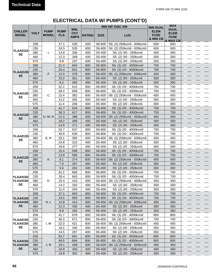
JOHnSOn COnTROLS66
FORm 150.72-nm1 (110)Technical Data
ELECTRICAL DATA W/ PUMPS (CONT’D)
CHILLERMODEL VOLT PUMP
MODELPUMPFLA
MIN.CKT
AMPS
MIN N/F DISC SW MIN DUALELEM FUSE
& MIN CB
MAX DUALELEM FUSE
& MAX CB
SYSTEM # 1 SYSTEM # 2
RATING SIZE LUGCOMPR 1 COMPR 2 COMPR 3 COND FANS COMPR 1 COMPR 2 COMPR 3 COND FANS
RLA LRA RLA LRA RLA LRA QTY FLA LRA RLA LRA RLA LRA RLA LRA QTY FLA LRA
YLAA0115SE
208
L
27.1 539 600 S6-600 S6: (2) 250kcmil - 500kcmil 600 600 109.6 599 109.6 599 3 7.6 30.9 109.6 599 109.6 599 3 7.6 30.9230 24.5 535 600 S6-600 S6: (2) 250kcmil - 500kcmil 600 600 109.6 599 109.6 599 3 7.4 37.0 109.6 599 109.6 599 3 7.4 37.0380 14.8 336 400 S5-400 S5: (2) 3/0 - 250kcmil 400 400 69.2 358 69.2 358 3 4.5 22.3 69.2 358 69.2 358 3 4.5 22.3460 12.3 268 400 S5-400 S5: (2) 3/0 - 250kcmil 300 300 54.5 310 54.5 310 3 4.0 19.0 54.5 310 54.5 310 3 4.0 19.0575 9.8 237 400 S5-400 S5: (2) 3/0 - 250kcmil 250 250 49.4 239 49.4 239 3 2.9 14.6 49.4 239 49.4 239 3 2.9 14.6
YLAA0135SE
208
F
21.4 604 800 S6-800 S6: (3) 2/0 - 4000kcmil 700 700 109.6 599 109.6 599 109.6 599 4 7.6 30.9 109.6 599 55.8 425 4 7.6 30.9230 20.4 601 800 S6-800 S6: (3) 2/0 - 4000kcmil 700 700 109.6 599 109.6 599 109.6 599 4 7.4 37.0 109.6 599 55.8 425 4 7.4 37.0380 12.0 378 600 S6-600 S6: (2) 250kcmil - 500kcmil 400 400 69.2 358 69.2 358 69.2 358 4 4.5 22.3 69.2 358 36.0 239 4 4.5 22.3460 10.2 301 400 S5-400 S5: (2) 3/0 - 250kcmil 350 350 54.5 310 54.5 310 54.5 310 4 4.0 19.0 54.5 310 26.9 187 4 4.0 19.0575 8.2 265 400 S5-400 S5: (2) 3/0 - 250kcmil 300 300 49.4 239 49.4 239 49.4 239 4 2.9 14.6 49.4 239 23.7 148 4 2.9 14.6
YLAA0135SE
208
C
32.2 615 800 S6-800 S6: (3) 2/0 - 4000kcmil 700 700 109.6 599 109.6 599 109.6 599 4 7.6 30.9 109.6 599 55.8 425 4 7.6 30.9230 28.4 609 800 S6-800 S6: (3) 2/0 - 4000kcmil 700 700 109.6 599 109.6 599 109.6 599 4 7.4 37.0 109.6 599 55.8 425 4 7.4 37.0380 15.4 382 600 S6-600 S6: (2) 250kcmil - 500kcmil 400 450 69.2 358 69.2 358 69.2 358 4 4.5 22.3 69.2 358 36.0 239 4 4.5 22.3460 14.2 305 400 S5-400 S5: (2) 3/0 - 250kcmil 350 350 54.5 310 54.5 310 54.5 310 4 4.0 19.0 54.5 310 26.9 187 4 4.0 19.0575 11.4 268 400 S5-400 S5: (2) 3/0 - 250kcmil 300 300 49.4 239 49.4 239 49.4 239 4 2.9 14.6 49.4 239 23.7 148 4 2.9 14.6
YLAA0135SE
208
D, m, n
41.7 624 800 S6-800 S6: (3) 2/0 - 4000kcmil 700 700 109.6 599 109.6 599 109.6 599 4 7.6 30.9 109.6 599 55.8 425 4 7.6 30.9230 36.3 617 800 S6-800 S6: (3) 2/0 - 4000kcmil 700 700 109.6 599 109.6 599 109.6 599 4 7.4 37.0 109.6 599 55.8 425 4 7.4 37.0380 22.0 388 600 S6-600 S6: (2) 250kcmil - 500kcmil 450 450 69.2 358 69.2 358 69.2 358 4 4.5 22.3 69.2 358 36.0 239 4 4.5 22.3460 18.2 309 400 S5-400 S5: (2) 3/0 - 250kcmil 350 350 54.5 310 54.5 310 54.5 310 4 4.0 19.0 54.5 310 26.9 187 4 4.0 19.0575 14.5 271 400 S5-400 S5: (2) 3/0 - 250kcmil 300 300 49.4 239 49.4 239 49.4 239 4 2.9 14.6 49.4 239 23.7 148 4 2.9 14.6
YLAA0135SE
208
E, R
54.7 637 800 S6-800 S6: (3) 2/0 - 4000kcmil 700 700 109.6 599 109.6 599 109.6 599 4 7.6 30.9 109.6 599 55.8 425 4 7.6 30.9230 49.5 630 800 S6-800 S6: (3) 2/0 - 4000kcmil 700 700 109.6 599 109.6 599 109.6 599 4 7.4 37.0 109.6 599 55.8 425 4 7.4 37.0380 29.1 395 600 S6-600 S6: (2) 250kcmil - 500kcmil 450 450 69.2 358 69.2 358 69.2 358 4 4.5 22.3 69.2 358 36.0 239 4 4.5 22.3460 24.8 315 400 S5-400 S5: (2) 3/0 - 250kcmil 350 350 54.5 310 54.5 310 54.5 310 4 4.0 19.0 54.5 310 26.9 187 4 4.0 19.0575 19.8 277 400 S5-400 S5: (2) 3/0 - 250kcmil 300 300 49.4 239 49.4 239 49.4 239 4 2.9 14.6 49.4 239 23.7 148 4 2.9 14.6
YLAA0135SE
208
K
15.4 598 800 S6-800 S6: (3) 2/0 - 4000kcmil 700 700 109.6 599 109.6 599 109.6 599 4 7.6 30.9 109.6 599 55.8 425 4 7.6 30.9230 13.9 595 800 S6-800 S6: (3) 2/0 - 4000kcmil 700 700 109.6 599 109.6 599 109.6 599 4 7.4 37.0 109.6 599 55.8 425 4 7.4 37.0380 8.1 374 600 S6-600 S6: (2) 250kcmil - 500kcmil 400 400 69.2 358 69.2 358 69.2 358 4 4.5 22.3 69.2 358 36.0 239 4 4.5 22.3460 7.0 297 400 S5-400 S5: (2) 3/0 - 250kcmil 350 350 54.5 310 54.5 310 54.5 310 4 4.0 19.0 54.5 310 26.9 187 4 4.0 19.0575 5.6 262 400 S5-400 S5: (2) 3/0 - 250kcmil 300 300 49.4 239 49.4 239 49.4 239 4 2.9 14.6 49.4 239 23.7 148 4 2.9 14.6
YLAA0150YLAA0155
SE
208
G
32.2 668 800 S6-800 S6: (3) 2/0 - 4000kcmil 700 700 109.6 599 109.6 599 109.6 599 4 7.6 30.9 109.6 599 109.6 599 4 7.6 30.9230 28.4 663 800 S6-800 S6: (3) 2/0 - 4000kcmil 700 700 109.6 599 109.6 599 109.6 599 4 7.4 37.0 109.6 599 109.6 599 4 7.4 37.0380 15.4 415 600 S6-600 S6: (2) 250kcmil - 500kcmil 450 450 69.2 358 69.2 358 69.2 358 4 4.5 22.3 69.2 358 69.2 358 4 4.5 22.3460 14.2 332 400 S5-400 S5: (2) 3/0 - 250kcmil 350 350 54.5 310 54.5 310 54.5 310 4 4.0 19.0 54.5 310 54.5 310 4 4.0 19.0575 11.4 294 400 S5-400 S5: (2) 3/0 - 250kcmil 350 350 49.4 239 49.4 239 49.4 239 4 2.9 14.6 49.4 239 49.4 239 4 2.9 14.6
YLAA0150YLAA0155
SE
208
H, L
27.1 663 800 S6-800 S6: (3) 2/0 - 4000kcmil 700 700 109.6 599 109.6 599 109.6 599 4 7.6 30.9 109.6 599 109.6 599 4 7.6 30.9230 24.5 659 800 S6-800 S6: (3) 2/0 - 4000kcmil 700 700 109.6 599 109.6 599 109.6 599 4 7.4 37.0 109.6 599 109.6 599 4 7.4 37.0380 14.8 414 600 S6-600 S6: (2) 250kcmil - 500kcmil 450 450 69.2 358 69.2 358 69.2 358 4 4.5 22.3 69.2 358 69.2 358 4 4.5 22.3460 12.3 330 400 S5-400 S5: (2) 3/0 - 250kcmil 350 350 54.5 310 54.5 310 54.5 310 4 4.0 19.0 54.5 310 54.5 310 4 4.0 19.0575 9.8 292 400 S5-400 S5: (2) 3/0 - 250kcmil 350 350 49.4 239 49.4 239 49.4 239 4 2.9 14.6 49.4 239 49.4 239 4 2.9 14.6
YLAA0150YLAA0155
SE
208
I, m
41.7 678 800 S6-800 S6: (3) 2/0 - 4000kcmil 800 800 109.6 599 109.6 599 109.6 599 4 7.6 30.9 109.6 599 109.6 599 4 7.6 30.9230 36.3 671 800 S6-800 S6: (3) 2/0 - 4000kcmil 700 700 109.6 599 109.6 599 109.6 599 4 7.4 37.0 109.6 599 109.6 599 4 7.4 37.0380 22.0 421 600 S6-600 S6: (2) 250kcmil - 500kcmil 450 450 69.2 358 69.2 358 69.2 358 4 4.5 22.3 69.2 358 69.2 358 4 4.5 22.3460 18.2 336 400 S5-400 S5: (2) 3/0 - 250kcmil 350 350 54.5 310 54.5 310 54.5 310 4 4.0 19.0 54.5 310 54.5 310 4 4.0 19.0575 14.5 297 400 S5-400 S5: (2) 3/0 - 250kcmil 350 350 49.4 239 49.4 239 49.4 239 4 2.9 14.6 49.4 239 49.4 239 4 2.9 14.6
YLAA0150YLAA0155
SE
208
J, R
54.7 691 800 S6-800 S6: (3) 2/0 - 4000kcmil 800 800 109.6 599 109.6 599 109.6 599 4 7.6 30.9 109.6 599 109.6 599 4 7.6 30.9230 49.5 684 800 S6-800 S6: (3) 2/0 - 4000kcmil 800 800 109.6 599 109.6 599 109.6 599 4 7.4 37.0 109.6 599 109.6 599 4 7.4 37.0380 29.1 428 600 S6-600 S6: (2) 250kcmil - 500kcmil 450 450 69.2 358 69.2 358 69.2 358 4 4.5 22.3 69.2 358 69.2 358 4 4.5 22.3460 24.8 343 400 S5-400 S5: (2) 3/0 - 250kcmil 400 400 54.5 310 54.5 310 54.5 310 4 4.0 19.0 54.5 310 54.5 310 4 4.0 19.0575 19.8 302 400 S5-400 S5: (2) 3/0 - 250kcmil 350 350 49.4 239 49.4 239 49.4 239 4 2.9 14.6 49.4 239 49.4 239 4 2.9 14.6

FORm 150.72-nm1 (110)
67JOHnSOn COnTROLS
55
CHILLERMODEL VOLT PUMP
MODELPUMPFLA
MIN.CKT
AMPS
MIN N/F DISC SW MIN DUALELEM FUSE
& MIN CB
MAX DUALELEM FUSE
& MAX CB
SYSTEM # 1 SYSTEM # 2
RATING SIZE LUGCOMPR 1 COMPR 2 COMPR 3 COND FANS COMPR 1 COMPR 2 COMPR 3 COND FANS
RLA LRA RLA LRA RLA LRA QTY FLA LRA RLA LRA RLA LRA RLA LRA QTY FLA LRA
YLAA0115SE
208
L
27.1 539 600 S6-600 S6: (2) 250kcmil - 500kcmil 600 600 109.6 599 109.6 599 3 7.6 30.9 109.6 599 109.6 599 3 7.6 30.9230 24.5 535 600 S6-600 S6: (2) 250kcmil - 500kcmil 600 600 109.6 599 109.6 599 3 7.4 37.0 109.6 599 109.6 599 3 7.4 37.0380 14.8 336 400 S5-400 S5: (2) 3/0 - 250kcmil 400 400 69.2 358 69.2 358 3 4.5 22.3 69.2 358 69.2 358 3 4.5 22.3460 12.3 268 400 S5-400 S5: (2) 3/0 - 250kcmil 300 300 54.5 310 54.5 310 3 4.0 19.0 54.5 310 54.5 310 3 4.0 19.0575 9.8 237 400 S5-400 S5: (2) 3/0 - 250kcmil 250 250 49.4 239 49.4 239 3 2.9 14.6 49.4 239 49.4 239 3 2.9 14.6
YLAA0135SE
208
F
21.4 604 800 S6-800 S6: (3) 2/0 - 4000kcmil 700 700 109.6 599 109.6 599 109.6 599 4 7.6 30.9 109.6 599 55.8 425 4 7.6 30.9230 20.4 601 800 S6-800 S6: (3) 2/0 - 4000kcmil 700 700 109.6 599 109.6 599 109.6 599 4 7.4 37.0 109.6 599 55.8 425 4 7.4 37.0380 12.0 378 600 S6-600 S6: (2) 250kcmil - 500kcmil 400 400 69.2 358 69.2 358 69.2 358 4 4.5 22.3 69.2 358 36.0 239 4 4.5 22.3460 10.2 301 400 S5-400 S5: (2) 3/0 - 250kcmil 350 350 54.5 310 54.5 310 54.5 310 4 4.0 19.0 54.5 310 26.9 187 4 4.0 19.0575 8.2 265 400 S5-400 S5: (2) 3/0 - 250kcmil 300 300 49.4 239 49.4 239 49.4 239 4 2.9 14.6 49.4 239 23.7 148 4 2.9 14.6
YLAA0135SE
208
C
32.2 615 800 S6-800 S6: (3) 2/0 - 4000kcmil 700 700 109.6 599 109.6 599 109.6 599 4 7.6 30.9 109.6 599 55.8 425 4 7.6 30.9230 28.4 609 800 S6-800 S6: (3) 2/0 - 4000kcmil 700 700 109.6 599 109.6 599 109.6 599 4 7.4 37.0 109.6 599 55.8 425 4 7.4 37.0380 15.4 382 600 S6-600 S6: (2) 250kcmil - 500kcmil 400 450 69.2 358 69.2 358 69.2 358 4 4.5 22.3 69.2 358 36.0 239 4 4.5 22.3460 14.2 305 400 S5-400 S5: (2) 3/0 - 250kcmil 350 350 54.5 310 54.5 310 54.5 310 4 4.0 19.0 54.5 310 26.9 187 4 4.0 19.0575 11.4 268 400 S5-400 S5: (2) 3/0 - 250kcmil 300 300 49.4 239 49.4 239 49.4 239 4 2.9 14.6 49.4 239 23.7 148 4 2.9 14.6
YLAA0135SE
208
D, m, n
41.7 624 800 S6-800 S6: (3) 2/0 - 4000kcmil 700 700 109.6 599 109.6 599 109.6 599 4 7.6 30.9 109.6 599 55.8 425 4 7.6 30.9230 36.3 617 800 S6-800 S6: (3) 2/0 - 4000kcmil 700 700 109.6 599 109.6 599 109.6 599 4 7.4 37.0 109.6 599 55.8 425 4 7.4 37.0380 22.0 388 600 S6-600 S6: (2) 250kcmil - 500kcmil 450 450 69.2 358 69.2 358 69.2 358 4 4.5 22.3 69.2 358 36.0 239 4 4.5 22.3460 18.2 309 400 S5-400 S5: (2) 3/0 - 250kcmil 350 350 54.5 310 54.5 310 54.5 310 4 4.0 19.0 54.5 310 26.9 187 4 4.0 19.0575 14.5 271 400 S5-400 S5: (2) 3/0 - 250kcmil 300 300 49.4 239 49.4 239 49.4 239 4 2.9 14.6 49.4 239 23.7 148 4 2.9 14.6
YLAA0135SE
208
E, R
54.7 637 800 S6-800 S6: (3) 2/0 - 4000kcmil 700 700 109.6 599 109.6 599 109.6 599 4 7.6 30.9 109.6 599 55.8 425 4 7.6 30.9230 49.5 630 800 S6-800 S6: (3) 2/0 - 4000kcmil 700 700 109.6 599 109.6 599 109.6 599 4 7.4 37.0 109.6 599 55.8 425 4 7.4 37.0380 29.1 395 600 S6-600 S6: (2) 250kcmil - 500kcmil 450 450 69.2 358 69.2 358 69.2 358 4 4.5 22.3 69.2 358 36.0 239 4 4.5 22.3460 24.8 315 400 S5-400 S5: (2) 3/0 - 250kcmil 350 350 54.5 310 54.5 310 54.5 310 4 4.0 19.0 54.5 310 26.9 187 4 4.0 19.0575 19.8 277 400 S5-400 S5: (2) 3/0 - 250kcmil 300 300 49.4 239 49.4 239 49.4 239 4 2.9 14.6 49.4 239 23.7 148 4 2.9 14.6
YLAA0135SE
208
K
15.4 598 800 S6-800 S6: (3) 2/0 - 4000kcmil 700 700 109.6 599 109.6 599 109.6 599 4 7.6 30.9 109.6 599 55.8 425 4 7.6 30.9230 13.9 595 800 S6-800 S6: (3) 2/0 - 4000kcmil 700 700 109.6 599 109.6 599 109.6 599 4 7.4 37.0 109.6 599 55.8 425 4 7.4 37.0380 8.1 374 600 S6-600 S6: (2) 250kcmil - 500kcmil 400 400 69.2 358 69.2 358 69.2 358 4 4.5 22.3 69.2 358 36.0 239 4 4.5 22.3460 7.0 297 400 S5-400 S5: (2) 3/0 - 250kcmil 350 350 54.5 310 54.5 310 54.5 310 4 4.0 19.0 54.5 310 26.9 187 4 4.0 19.0575 5.6 262 400 S5-400 S5: (2) 3/0 - 250kcmil 300 300 49.4 239 49.4 239 49.4 239 4 2.9 14.6 49.4 239 23.7 148 4 2.9 14.6
YLAA0150YLAA0155
SE
208
G
32.2 668 800 S6-800 S6: (3) 2/0 - 4000kcmil 700 700 109.6 599 109.6 599 109.6 599 4 7.6 30.9 109.6 599 109.6 599 4 7.6 30.9230 28.4 663 800 S6-800 S6: (3) 2/0 - 4000kcmil 700 700 109.6 599 109.6 599 109.6 599 4 7.4 37.0 109.6 599 109.6 599 4 7.4 37.0380 15.4 415 600 S6-600 S6: (2) 250kcmil - 500kcmil 450 450 69.2 358 69.2 358 69.2 358 4 4.5 22.3 69.2 358 69.2 358 4 4.5 22.3460 14.2 332 400 S5-400 S5: (2) 3/0 - 250kcmil 350 350 54.5 310 54.5 310 54.5 310 4 4.0 19.0 54.5 310 54.5 310 4 4.0 19.0575 11.4 294 400 S5-400 S5: (2) 3/0 - 250kcmil 350 350 49.4 239 49.4 239 49.4 239 4 2.9 14.6 49.4 239 49.4 239 4 2.9 14.6
YLAA0150YLAA0155
SE
208
H, L
27.1 663 800 S6-800 S6: (3) 2/0 - 4000kcmil 700 700 109.6 599 109.6 599 109.6 599 4 7.6 30.9 109.6 599 109.6 599 4 7.6 30.9230 24.5 659 800 S6-800 S6: (3) 2/0 - 4000kcmil 700 700 109.6 599 109.6 599 109.6 599 4 7.4 37.0 109.6 599 109.6 599 4 7.4 37.0380 14.8 414 600 S6-600 S6: (2) 250kcmil - 500kcmil 450 450 69.2 358 69.2 358 69.2 358 4 4.5 22.3 69.2 358 69.2 358 4 4.5 22.3460 12.3 330 400 S5-400 S5: (2) 3/0 - 250kcmil 350 350 54.5 310 54.5 310 54.5 310 4 4.0 19.0 54.5 310 54.5 310 4 4.0 19.0575 9.8 292 400 S5-400 S5: (2) 3/0 - 250kcmil 350 350 49.4 239 49.4 239 49.4 239 4 2.9 14.6 49.4 239 49.4 239 4 2.9 14.6
YLAA0150YLAA0155
SE
208
I, m
41.7 678 800 S6-800 S6: (3) 2/0 - 4000kcmil 800 800 109.6 599 109.6 599 109.6 599 4 7.6 30.9 109.6 599 109.6 599 4 7.6 30.9230 36.3 671 800 S6-800 S6: (3) 2/0 - 4000kcmil 700 700 109.6 599 109.6 599 109.6 599 4 7.4 37.0 109.6 599 109.6 599 4 7.4 37.0380 22.0 421 600 S6-600 S6: (2) 250kcmil - 500kcmil 450 450 69.2 358 69.2 358 69.2 358 4 4.5 22.3 69.2 358 69.2 358 4 4.5 22.3460 18.2 336 400 S5-400 S5: (2) 3/0 - 250kcmil 350 350 54.5 310 54.5 310 54.5 310 4 4.0 19.0 54.5 310 54.5 310 4 4.0 19.0575 14.5 297 400 S5-400 S5: (2) 3/0 - 250kcmil 350 350 49.4 239 49.4 239 49.4 239 4 2.9 14.6 49.4 239 49.4 239 4 2.9 14.6
YLAA0150YLAA0155
SE
208
J, R
54.7 691 800 S6-800 S6: (3) 2/0 - 4000kcmil 800 800 109.6 599 109.6 599 109.6 599 4 7.6 30.9 109.6 599 109.6 599 4 7.6 30.9230 49.5 684 800 S6-800 S6: (3) 2/0 - 4000kcmil 800 800 109.6 599 109.6 599 109.6 599 4 7.4 37.0 109.6 599 109.6 599 4 7.4 37.0380 29.1 428 600 S6-600 S6: (2) 250kcmil - 500kcmil 450 450 69.2 358 69.2 358 69.2 358 4 4.5 22.3 69.2 358 69.2 358 4 4.5 22.3460 24.8 343 400 S5-400 S5: (2) 3/0 - 250kcmil 400 400 54.5 310 54.5 310 54.5 310 4 4.0 19.0 54.5 310 54.5 310 4 4.0 19.0575 19.8 302 400 S5-400 S5: (2) 3/0 - 250kcmil 350 350 49.4 239 49.4 239 49.4 239 4 2.9 14.6 49.4 239 49.4 239 4 2.9 14.6

JOHnSOn COnTROLS68
FORm 150.72-nm1 (110)Technical Data
ELECTRICAL NOTES AND LEGEND
DESIGNATION DESCRIPTIONACC ACCESSORY
- ADIS DISPLAY BOARD
- AmB mICRO BOARD
- BAmB AmBIEnT
- BDAT DISCHARGE AIR TEmPERATURE
- BDP DISCHARGE PRESSURE
- BECT EnTRInG CHILLED TEmPERATURE
- BLCT LEAvInG CHILLED TEmPERATUREnOT FITTED On REmOTE EvAP UnITS
-BmP mOTOR PROTECTOR COmPRESSOR
- BSP SUCTIOn PRESSURE
- CPF CAPACITOR POWER FACTOR
- ECH CRAnKCASE HEATER
- EEH EvAPORATOR HEATER
- EHRH HEAT RECOvERY HEATER
- EPH PUmP HEATER
- EXT EXTERnAL TO COnTROL PAnEL
- F FUSE
- FHP HIGH PRESSURE CUTOUT
- FSC FAn SPEED COnTROLLER
- FSI FAn SPEED InHIBIT TWO SPEEDFAn OPTIOn OnLY
GnD GROUnD
G/Y GREEn / YELLOW
J PLUG BOARD COnnECTOR
- K CIRCUIT BOARD RELAY
- KF FAn COnTACTOR LInE(InCLUDInG COIL SUPPRESSOR)
- KFH FAn COnTACTOR HIGH SPEED(InCLUDInG COIL SUPPRESSOR)
- KFL FAn COnTACTOR LOW SPEED(InCLUDInG COIL SUPPRESSOR)
- KFOL FAn OvERLOAD
- KFS RELAY FAn SPEED
- KH HEATER RELAY
- Km COmPRESSOR COnTACTOR (InCLUD-InG COIL SUPPRESSOR)
- KCR COnTROL RELAY
- KP PUmP COnTACTOR PART(InCLUDInG COIL SUPPRESSOR)
- KT RELAY TImER
- m COmPRESSOR mOTOR
DESIGNATION DESCRIPTION- mF mOTOR FAn
- mP mOTOR PUmP
nU nOT USED
PE PROTECTIvE EARTH
PWm PULSE WIDTH mODULATIOn TEmP RE-SET or REmOTE UnLOAD 2nd STEP
- qCB CIRCUIT BREAKER
- qmmSC mAnUAL mOTOR STARTER COmPRESSOR
- qmmSP mAnUAL mOTOR STARTER PUmP
- qSD SWITCH DISCOnnECT
R RESISTOR
RED RED
RP RUn PERmISSIvE
RU REmOTE UnLOAD 1st STEP
SCH THERmOSTAT CRAnKCASE HEATER
SCR SCREEn
- SF FLOW SWITCH
- SKP KEYPAD
- SOA SWITCH OFF AUTO
- SZT ZOnE THERmOSTAT
- T TRAnSFORmER
- TC TRAnSFORmER CURREnT
- UBR BRIGDE RECFIFIER
- WHT WHITE
- XP PLUGS BETWEEn POW./mICROBOARD.SECTIOn
- XTBC TERmInAL BLOCK CUSTOmER
- XTBF TERmInAL BLOCK FACTORY
- YESv EvAPORATOR SOLEnOID vALvE
- YHGSv HOT GAS SOLEnOID vALvE (InCLUDInG COIL SUPPRESSOR)
- YLLSvLIqUID LInE SOLEnOID vALvE FIELD mOUnTED AnD WIRED On REmOTE EvAP. UnITS
- ZCPR COmPRESSOR
nB nOTE WELL {SEE nOTE}
WIRInG AnD ITEmS SHOWn THUS ARE STAnDARD YORK ACCESSORIES
WIRInG AnD ITEmS SHOWn THUS ARE nOT SUPPLIED BY YORK
ITEmS THUS EnCLOSED FORm A COm-POnEnTS OR SETS OF COmPOnEnTS
035-21966-101 REvG

FORm 150.72-nm1 (110)
69JOHnSOn COnTROLS
55
ELECTRICAL NOTES AND LEGEND (CONT’D)
GENERALA. This drawing is based on IEC symbols.
B. Field wiring to be in accordance with the relevant electrical code as well as all other applicable codes and specifications.
C. All sources of supply shown on this diagram to be taken from one main isolator, not shown or supplied by YORK.
D.Green and yellow wire is used for earth, multi-colored cable used for low voltage. Red wire used for AC Control, blue wire for neutral, black wire for AC and DC power. Orange wire should be used for interlock control wiring supplied by external source.
E. Legend designation depicts component abbreviations. Number prefix located, if applicable, on schematic circuit, refers to system thereon, E.G. = 1-FHP2 refers to high pressure cutout no 2 on system no 1.
F.
All wiring to control section voltage free contacts requires a supply provided by the customer maximum voltage 120 volts. The customer must take particular care when deriving the supplies for the voltage free terminals with regard to a common point of isolation. Thus, these circuits when used must be fed via the common point of isolation the voltage to these circuits is removed when the common point of isolation to the unit is opened. This common point of isolation is not supplied by YORK. The YORK voltage free contacts are rated at 100va. All inductive devices {relays} switch by the YORK voltage free contacts must have their coil suppressed using standard R/C suppressors.
G. Customer voltage free contacts connected to terminal 13 must be rated at 30v 5ma.
H.no controls {relays etc.} Should be mounted in any section of the control panel. Additionally, control wiring not connected to the YORK control panel should not be run through the panel. If these precautions are not followed, electrical noise could cause malfunctions or damage to the unit and its controls.
I. 120/14.3 - (Signal In/OUT) i.e. 120 is wire # and 14.3 refers to SHT. 14 column 3.Notes
1 Refer to installation commissioning operation and maintenance manual for customer connections and customer connection notes, non compliance to these instructions will invalidate unit warranty.
2 Wiring and components for compressor 3 only fitted when unit has 3 compressors on the system. 1-BMP3 is replaced by a link across terminals 134 & 135. 2-BmP3 is replaced by a link across terminals 234 & 235.
34 Fitted on units with hot gas bypass option.5 EmS option is wired as shown.6 This wiring must be used for old display 031-0110-000.7 network connection point.8 Printer port.9 Remote emergency stop can be wired between terminal l and 5 after removing link.10 Power factor correction accessory. Power factor correction fitted to each compressor contactor.
11 Not fitted on compressors with internal motor protection. For system 1 terminals 132 & 133, 133 & 134 and 134 & 135 are linked. For system 2 terminals 232 & 233, 233 & 234 and 234 & 235 are linked.
12 Only fitted on systems with 3 or 4 fans.13 Only fitted on systems with 4 fans.14 Only fitted on systems with 5 fans.15 Only fitted on systems with 6 fans.16 Input switch disconnect (standard on CE units) or circuit breaker option replaces input terminal block.17 Input switch disconnect & individual system circuit breaker option replaces input terminal block.
18 115V control circuit requires a 115V supply unless control circuit transformer -T2 & -F3 are fitted (standard on CE units).
19For optional hydro kit. Heater -EPH is fitted and wired as shown. On single pump -KP1, -QMMSP1 & -MP1 are fitted & wired as shown. On two pump hydro kits -KP2, -QMMSP2 & -MP2 are also fitted and wired as shown.
20 Current measurement option wired as show.21 Only fitted on systems with single speed fans.
035-21966-101 REv G
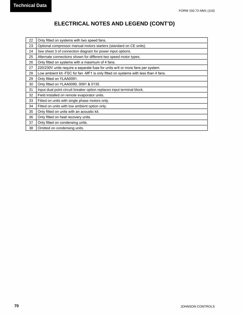
JOHnSOn COnTROLS70
FORm 150.72-nm1 (110)Technical Data
22 Only fitted on systems with two speed fans.23 Optional compressor manual motors starters (standard on CE units).24 See sheet 3 of connection diagram for power input options.25 Alternate connections shown for different two speed motor types.26 Only fitted on systems with a maximum of 4 fans.27 220/230V units require a separate fuse for units w/4 or more fans per system.28 Low ambient kit -FSC for fan -MF1 is only fitted on systems with less than 4 fans.29 Only fitted on YLAA0091.30 Only fitted on YLAA0090, 0091 & 0135.31 Input dual point circuit breaker option replaces input terminal block.32 Field installed on remote evaporator units.33 Fitted on units with single phase motors only.34 Fitted on units with low ambient option only.35 Only fitted on units with an acoustic kit.36 Only fitted on heat recovery units.37 Only fitted on condensing units.38 Omitted on condensing units.
ELECTRICAL NOTES AND LEGEND (CONT’D)

FORm 150.72-nm1 (110)
71JOHnSOn COnTROLS
THIS PAGE INTENTIONALLY LEFT BLANK
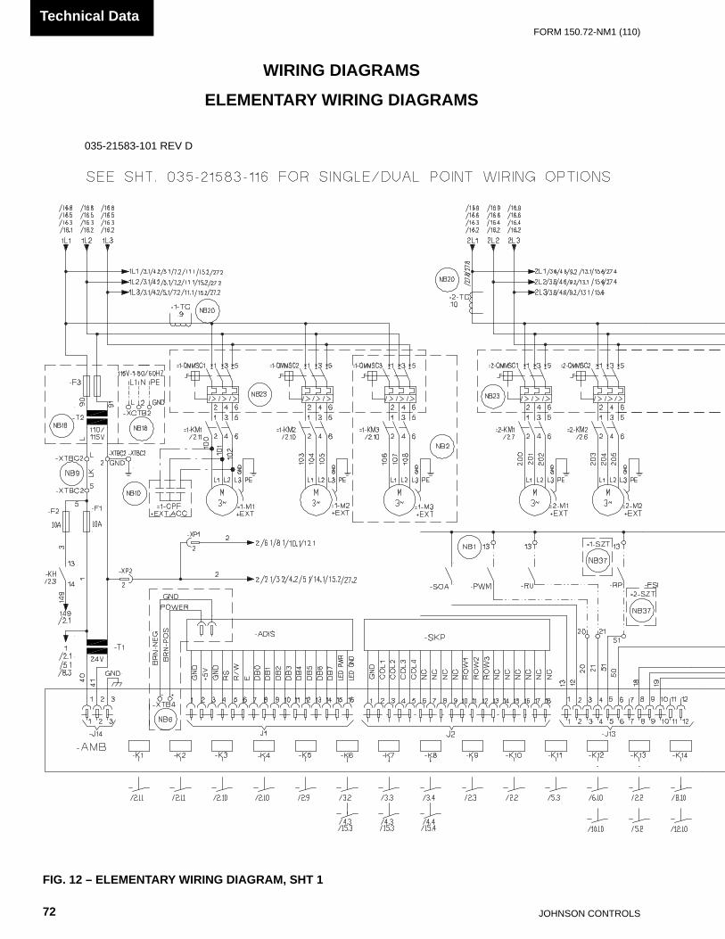
JOHnSOn COnTROLS72
FORm 150.72-nm1 (110)Technical Data
WIRING DIAGRAMS
FIG. 12 – ELEMENTARY WIRING DIAGRAM, SHT 1
ELEMENTARY WIRING DIAGRAMS
035-21583-101 REV D035-21583-101 REv D

FORm 150.72-nm1 (110)
73JOHnSOn COnTROLS
55
035-21583-101 REV D
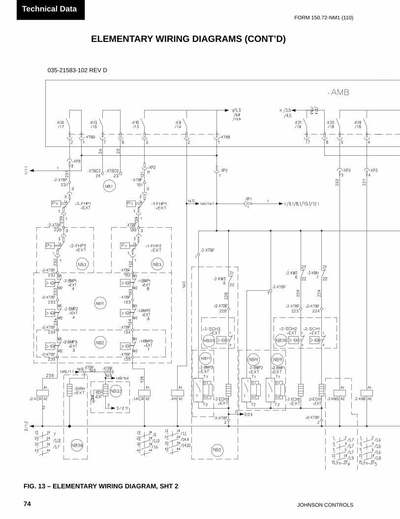
JOHnSOn COnTROLS74
FORm 150.72-nm1 (110)Technical Data
FIG. 13 – ELEMENTARY WIRING DIAGRAM, SHT 2
035-21583-102 REV D035-21583-102 REv D
ELEMENTARY WIRING DIAGRAMS (CONT’D)

FORm 150.72-nm1 (110)
75JOHnSOn COnTROLS
55
035-21583-102 REV D

JOHnSOn COnTROLS76
FORm 150.72-nm1 (110)Technical Data
FIG. 14 – ELEMENTARY WIRING DIAGRAM, SHT 3
FAN WIRING
035-21583-103 REv B
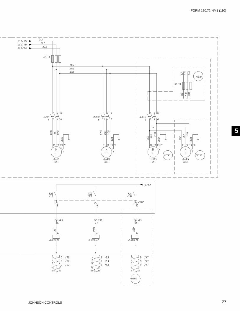
FORm 150.72-nm1 (110)
77JOHnSOn COnTROLS
55

JOHnSOn COnTROLS78
FORm 150.72-nm1 (110)Technical Data
FIG. 15 – ELEMENTARY WIRING DIAGRAM, SHT 4
035-21583-104 REv B
FAN WIRING (CONT’D)

FORm 150.72-nm1 (110)
79JOHnSOn COnTROLS
55

JOHnSOn COnTROLS80
FORm 150.72-nm1 (110)Technical Data
POWER PANEL
FIG. 16 – CONNECTION DIAGRAM, SHT 1
035-21589-101 REV C035-21589-101 REv C
CONNECTION DIAGRAMS

FORm 150.72-nm1 (110)
81JOHnSOn COnTROLS
55
035-21589-101 REV C

JOHnSOn COnTROLS82
FORm 150.72-nm1 (110)Technical Data
MICRO PANEL CONECTIONS
FIG. 17 – CONNECTION DIAGRAM, SHT 2
035-21589-102 REV D035-21589-102 REv D

FORm 150.72-nm1 (110)
83JOHnSOn COnTROLS
55
035-21589-102 REV D
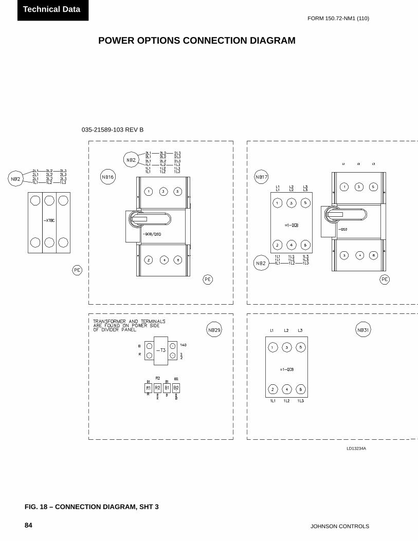
JOHnSOn COnTROLS84
FORm 150.72-nm1 (110)Technical Data
POWER OPTIONS CONNECTION DIAGRAM
FIG. 18 – CONNECTION DIAGRAM, SHT 3
LD13234A
035-21589-103 REVB035-21589-103 REv B
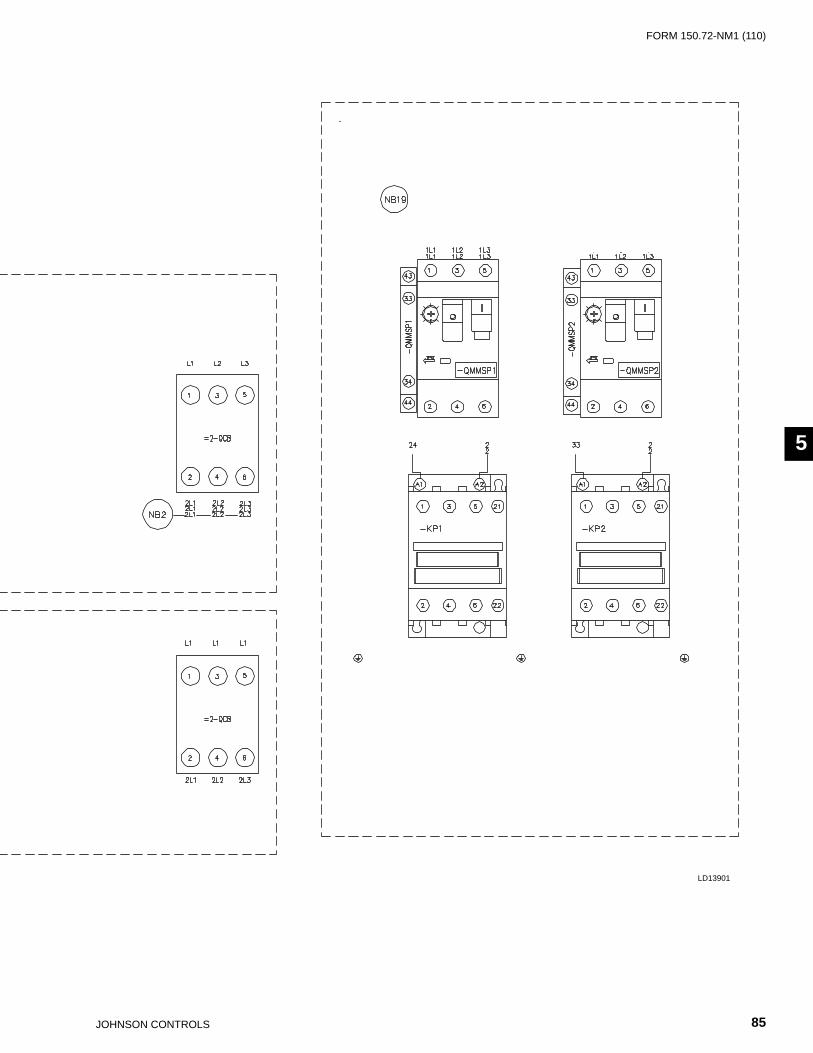
FORm 150.72-nm1 (110)
85JOHnSOn COnTROLS
55
LD13901
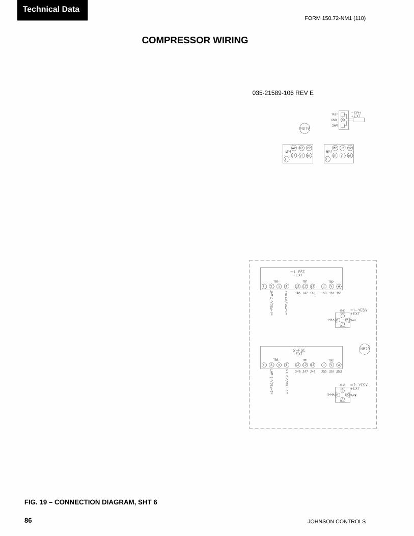
JOHnSOn COnTROLS86
FORm 150.72-nm1 (110)Technical Data
COMPRESSOR WIRING
FIG. 19 – CONNECTION DIAGRAM, SHT 6
035-21589-106 REV E035-21589-106 REv E
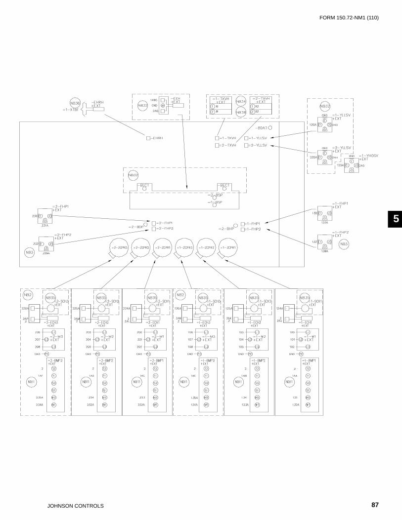
FORm 150.72-nm1 (110)
87JOHnSOn COnTROLS
55
035-21589-106 REV E

JOHnSOn COnTROLS88
FORm 150.72-nm1 (110)Technical Data
CONDENSER FAN MAPPING AND SEQUENCING
LD13147
FIG. 20 – CONNECTION DIAGRAM, SHT 7
035-21589-107 REv A

FORm 150.72-nm1 (110)
89JOHnSOn COnTROLS
55
LD13232

JOHnSOn COnTROLS90
FORm 150.72-nm1 (110)Technical Data
DUAL PUMP WIRING
LD13237
FIG. 21 – DUAL PUMP WIRING

FORm 150.72-nm1 (110)
91JOHnSOn COnTROLS
THIS PAGE INTENTIONALLY LEFT BLANK

JOHnSOn COnTROLS92
FORm 150.72-nm1 (110)Technical Data
WIRING
LD13238FIG. 22 – WIRING
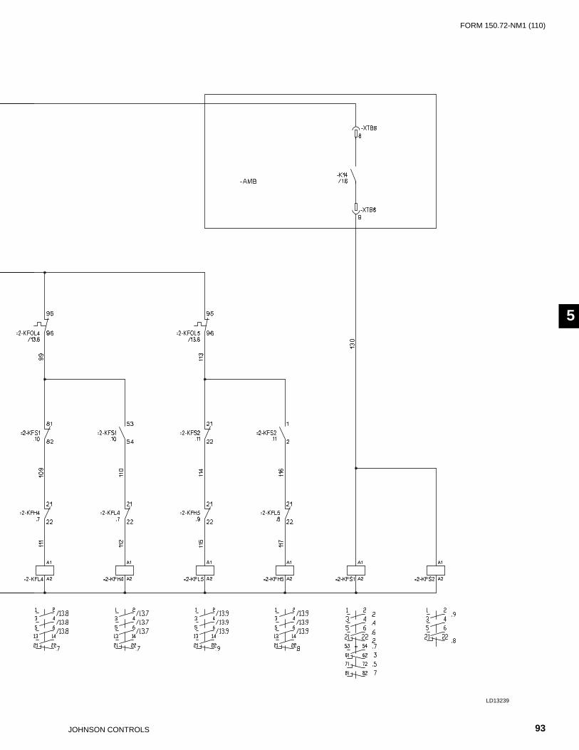
FORm 150.72-nm1 (110)
93JOHnSOn COnTROLS
55
LD13239

JOHnSOn COnTROLS94
FORm 150.72-nm1 (110)Technical Data
FIG. 23 – WIRING DIAGRAM, SINGLE POINT WIRING OPTIONS
WIRING DIAGRAM - POWER SUPPLY
SINGLE POINT WIRING OPTIONS
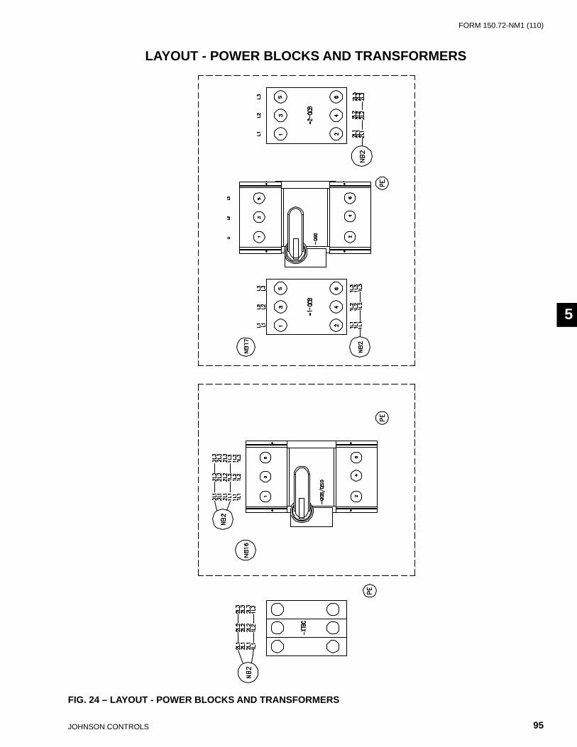
FORm 150.72-nm1 (110)
95JOHnSOn COnTROLS
55
LAYOUT - POWER BLOCKS AND TRANSFORMERS
FIG. 24 – LAYOUT - POWER BLOCKS AND TRANSFORMERS

JOHnSOn COnTROLS96
FORm 150.72-nm1 (110)Technical Data
DIMENSIONS – YLAA0070 TO 0090 (ENGLISH)FOUR FAN UNITS
DIMENSIONS (ENGLISH)
F
W
P
D
C1
R2
C2
H
R1TYP
L
YLAA Model L (length) W (width) H (height) F P D C1 C2 R2 R1YLAA0070SE 116 88.3 94.2 88.5 42.8 13.4 19 84.5 68.3 23YLAA0080SE 116 88.3 94.2 88.5 42.8 15 18.6 85 68.3 23YLAA0090SE 116 88.3 94.2 88.5 42.8 16.3 19.6 83 68.3 23
NOTE: Placement on a level surface of free of obstructions (including snow, for winter operation) or air circulation ensures rated performance, reliable
operation, and ease of maintenance. Site restrictions may compromise minimum clearances indicated below, resulting in unpredictable airflow pat-terns and possible diminished performance. Johnson Controls unit controls will optimize operation without nuisance high-pressure safety cutouts; however, the system designer must consider potential performance degradation. Access to the unit control center assumes the unit is no higher than on spring isolators. Recommended minimum clearances: Side to wall – 6'; rear to wall – 6'; control panel to end wall – 4'0''; top – no obstructions allowed; distance between adjacent units – 10'. no more than one adjacent wall may be higher than the unit.
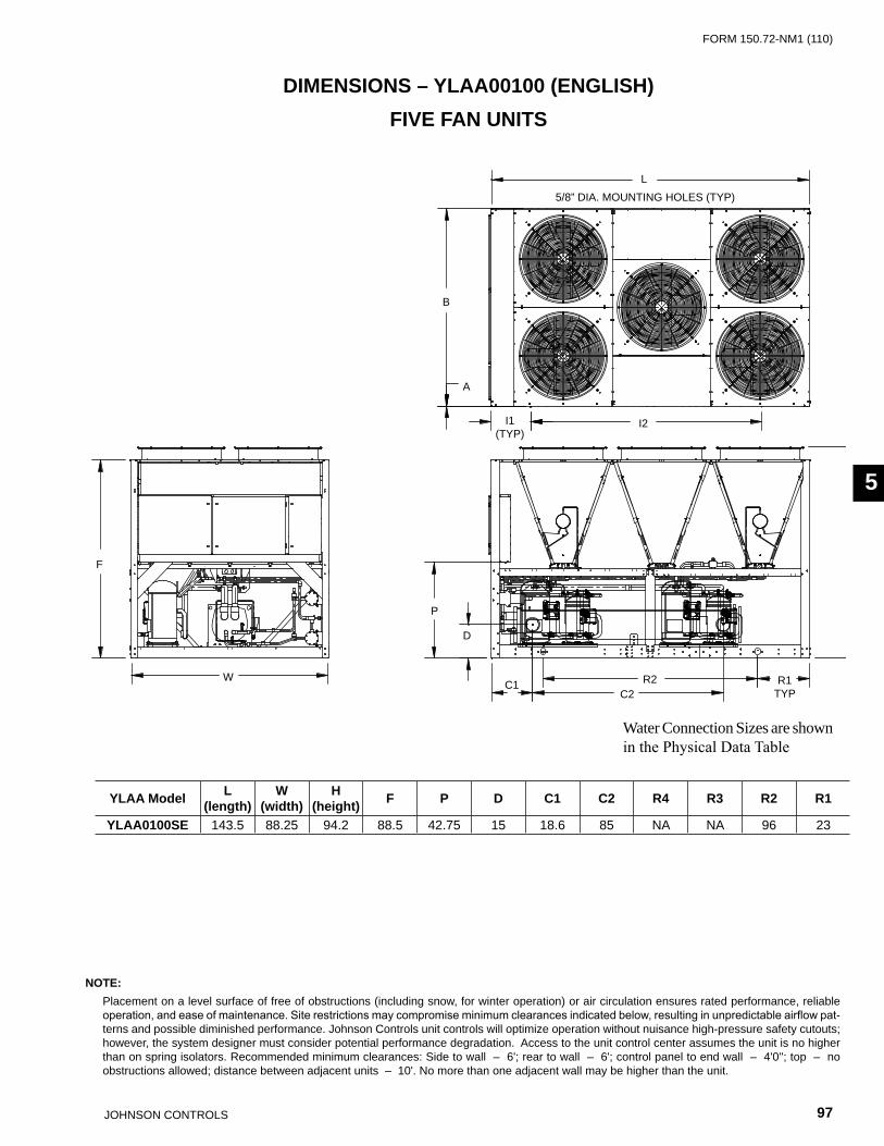
FORm 150.72-nm1 (110)
97JOHnSOn COnTROLS
55
Water Connection Sizes are shown in the Physical Data Table
F
W
P
D
C1C2
R2 R1TYP
H
B
A
I1(TYP)
I2
L
5/8” DIA. MOUNTING HOLES (TYP)
YLAA Model L (length)
W (width)
H (height) F P D C1 C2 R4 R3 R2 R1
YLAA0100SE 143.5 88.25 94.2 88.5 42.75 15 18.6 85 nA nA 96 23
NOTE: Placement on a level surface of free of obstructions (including snow, for winter operation) or air circulation ensures rated performance, reliable
operation, and ease of maintenance. Site restrictions may compromise minimum clearances indicated below, resulting in unpredictable airflow pat-terns and possible diminished performance. Johnson Controls unit controls will optimize operation without nuisance high-pressure safety cutouts; however, the system designer must consider potential performance degradation. Access to the unit control center assumes the unit is no higher than on spring isolators. Recommended minimum clearances: Side to wall – 6'; rear to wall – 6'; control panel to end wall – 4'0''; top – no obstructions allowed; distance between adjacent units – 10'. no more than one adjacent wall may be higher than the unit.
DIMENSIONS – YLAA00100 (ENGLISH)FIVE FAN UNITS
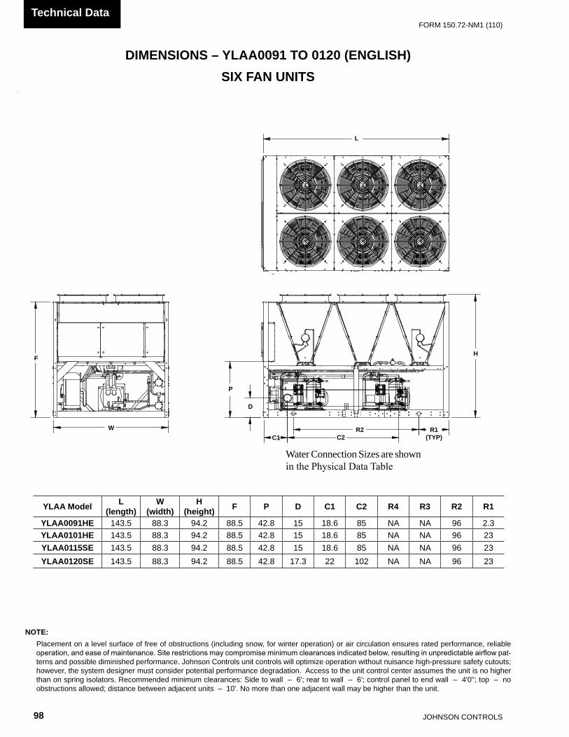
JOHnSOn COnTROLS98
FORm 150.72-nm1 (110)Technical Data
DIMENSIONS – YLAA0091 TO 0120 (ENGLISH)
Water Connection Sizes are shown in the Physical Data Table
F
W
P
D
C1 C2R2 R1
(TYP)
H
L
YLAA Model L (length)
W (width)
H (height) F P D C1 C2 R4 R3 R2 R1
YLAA0091HE 143.5 88.3 94.2 88.5 42.8 15 18.6 85 nA nA 96 2.3YLAA0101HE 143.5 88.3 94.2 88.5 42.8 15 18.6 85 nA nA 96 23YLAA0115SE 143.5 88.3 94.2 88.5 42.8 15 18.6 85 nA nA 96 23YLAA0120SE 143.5 88.3 94.2 88.5 42.8 17.3 22 102 nA nA 96 23
NOTE: Placement on a level surface of free of obstructions (including snow, for winter operation) or air circulation ensures rated performance, reliable
operation, and ease of maintenance. Site restrictions may compromise minimum clearances indicated below, resulting in unpredictable airflow pat-terns and possible diminished performance. Johnson Controls unit controls will optimize operation without nuisance high-pressure safety cutouts; however, the system designer must consider potential performance degradation. Access to the unit control center assumes the unit is no higher than on spring isolators. Recommended minimum clearances: Side to wall – 6'; rear to wall – 6'; control panel to end wall – 4'0''; top – no obstructions allowed; distance between adjacent units – 10'. no more than one adjacent wall may be higher than the unit.
SIX FAN UNITS

FORm 150.72-nm1 (110)
99JOHnSOn COnTROLS
55
DIMENSIONS – YLAA0125 - 0155 (ENGLISH)
Water connection sizes are shown in Physical Data (Table 4).
F
W
P
D
C1 C2
R2 R1
H
L
NOTE: Placement on a level surface of free of obstructions (including snow, for winter operation) or air circulation ensures rated performance, reliable
operation, and ease of maintenance. Site restrictions may compromise minimum clearances indicated below, resulting in unpredictable airflow pat-terns and possible diminished performance. Johnson Controls unit controls will optimize operation without nuisance high-pressure safety cutouts; however, the system designer must consider potential performance degradation. Access to the unit control center assumes the unit is no higher than on spring isolators. Recommended minimum clearances: Side to wall – 6'; rear to wall – 6'; control panel to end wall – 4'0''; top – no obstructions allowed; distance between adjacent units – 10'. no more than one adjacent wall may be higher than the unit.
YLAA Models L (length)
W (width)
H (height) F P D C1 C2 R4 R3 R2 R1
YLAA0125HE 187.5 88.3 94.2 88.5 42.8 15 18.6 85 nA 58 66 39YLAA0135SE 187.5 88.3 94.2 88.5 42.8 16.3 19.6 83 nA 58 66 39YLAA0141HE 187.5 88.3 94.2 88.5 42.8 16.3 22.1 102 nA 58 66 39YLAA0150SE 187.5 88.3 94.2 88.5 42.8 16.3 19.6 83 nA 58 66 39YLAA0155SE 187.5 88.3 94.2 88.5 42.8 16.3 22 102 nA 58 66 39
EIGHT FAN UNITS

JOHnSOn COnTROLS100
FORm 150.72-nm1 (110)Technical Data
L
5/8" DIA. MOUNTING HOLES (TYP)
A
B
I1(TYP)
I2 I3
H
R1(TYP)
R2
C1C2
D
P
F
W
YLAA Model L (length)
W (width)
H (height) F P D C1 C2 R4 R3 R2 R1
YLAA0156HE 232.7 88.25 94.2 88.5 42.75 16.25 19.6 83 58.0 43 83 23YLAA0170SE 232.7 88.25 94.2 88.5 42.75 16.25 19.6 83 58.0 43 83 23YLAA0175HE 232.7 88.25 94.2 88.5 42.75 17.25 22.13 102 58.0 43 83 23
DIMENSIONS – YLAA0156 - 0175 (ENGLISH)
NOTE: Placement on a level surface of free of obstructions (including snow, for winter operation) or air circulation ensures rated performance, reliable
operation, and ease of maintenance. Site restrictions may compromise minimum clearances indicated below, resulting in unpredictable airflow pat-terns and possible diminished performance. Johnson Controls unit controls will optimize operation without nuisance high-pressure safety cutouts; however, the system designer must consider potential performance degradation. Access to the unit control center assumes the unit is no higher than on spring isolators. Recommended minimum clearances: Side to wall – 6'; rear to wall – 6'; control panel to end wall – 4'0''; top – no obstructions allowed; distance between adjacent units – 10'. no more than one adjacent wall may be higher than the unit.
TEN FAN UNITS

FORm 150.72-nm1 (110)
101JOHnSOn COnTROLS
55
TECHNICAL DATA – CLEARANCES
NOTES:1. no obstructions allowed above the unit.2. Only one adjacent wall may be higher than the unit.3. Adjacent units should be 10 feet (3 meters) apart.
LD13243
FIG. 25 – UNIT CLEARANCES – ALL MODELS
(1.3 m) (2 m)(2
m)
(2 m
)
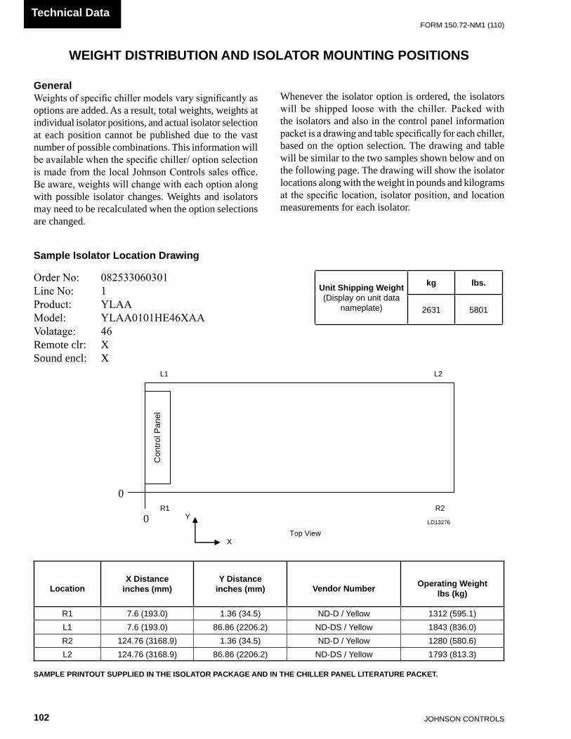
JOHnSOn COnTROLS102
FORm 150.72-nm1 (110)Technical Data
WEIGHT DISTRIBUTION AND ISOLATOR MOUNTING POSITIONS
GeneralWeights of specific chiller models vary significantly as options are added. As a result, total weights, weights at individual isolator positions, and actual isolator selection at each position cannot be published due to the vast number of possible combinations. This information will be available when the specific chiller/ option selection is made from the local Johnson Controls sales office. Be aware, weights will change with each option along with possible isolator changes. Weights and isolators may need to be recalculated when the option selections are changed.
Whenever the isolator option is ordered, the isolators will be shipped loose with the chiller. Packed with the isolators and also in the control panel information packet is a drawing and table specifically for each chiller, based on the option selection. The drawing and table will be similar to the two samples shown below and on the following page. The drawing will show the isolator locations along with the weight in pounds and kilograms at the specific location, isolator position, and location measurements for each isolator.
Sample Isolator Location Drawing
LocationX Distance
inches (mm)Y Distance
inches (mm) Vendor Number Operating Weightlbs (kg)
R1 7.6 (193.0) 1.36 (34.5) nD-D / Yellow 1312 (595.1)L1 7.6 (193.0) 86.86 (2206.2) nD-DS / Yellow 1843 (836.0)R2 124.76 (3168.9) 1.36 (34.5) nD-D / Yellow 1280 (580.6)L2 124.76 (3168.9) 86.86 (2206.2) nD-DS / Yellow 1793 (813.3)
SAMPLE PRINTOUT SUPPLIED IN THE ISOLATOR PACKAGE AND IN THE CHILLER PANEL LITERATURE PACKET.
Order No: 082533060301Line No: 1Product: YLAAModel: YLAA0101HE46XAAVolatage: 46Remote clr: XSound encl: X
Unit Shipping Weight(Display on unit data
nameplate)
kg lbs.
2631 5801
0
Con
trol
Pan
el
0 R1 R2
L1 L2
X
Y
Top View
LD13276

FORm 150.72-nm1 (110)
103JOHnSOn COnTROLS
55
ISOLATOR LOCATIONS
I, I5 I2, I6A
B
TYP TYP
I, I5 I2, I6 I3, I7 A
B
TYP TYP TYP
YLAA ModelAVM LOCATIONS
I1 I2 I3 I4 I5 I6 I7 I8 A BYLAA0070SE 19.5 76.6 19.5 76.6 1.4 85.5YLAA0080SE 19.5 76.6 19.5 76.6 1.4 85.5YLAA0090SE 19.5 76.6 19.5 76.6 1.4 85.5
YLAA Model AVM LOCATIONSI1 I2 I3 I4 I5 I6 I7 I8 A B
YLAA0091HE 7.6 117.2 7.6 117.2 1.4 85.5YLAA0100SE 7.6 117.2 7.6 117.2 1.36 85.5YLAA0101HE 7.6 117.2 7.6 117.2 1.36 85.5YLAA0115SE 7.6 117.2 7.6 117.2 1.36 85.5YLAA0120SE 7.6 117.2 7.6 117.2 1.36 85.5
I1, 15
TYP
nOTE: All dimensions in inches.
I1, 15
TYP

JOHnSOn COnTROLS104
FORm 150.72-nm1 (110)Technical Data
I, I5 I2, I6 I3, I7 A
B
TYP TYP TYP
ISOLATOR LOCATIONS (CONT’D)
nOTE: All dimensions in inches.
I1, 15
TYP
YLAA ModelAVM LOCATIONS
I1 I2 I3 I4 I5 I6 I7 I8 A BYLAA0125HE 7.6 69 80 7.6 69 80 1.4 85.5YLAA0135SE 7.6 69 80 7.6 69 80 1.4 85.5YLAA0141HE 7.6 69 80 7.6 69 80 1.4 85.5YLAA0150SE 7.6 69 80 7.6 69 80 1.4 85.5YLAA0155SE 7.6 69 80 7.6 69 80 1.4 85.5

FORm 150.72-nm1 (110)
105JOHnSOn COnTROLS
55
I2, I6 I3, I7 I4, I8
B
I1, I5
A
CO
NT
RO
L P
AN
EL
EN
D
YLAA Model
AVM LOCATIONSI1 I2 I3 I4 I5 I6 I7 I8 A B
YLAA0156HE 7.6 69 72.5 63.6 7.6 69 72.5 63.6 1.36 85.5YLAA0170SE 7.6 69 72.5 63.6 7.6 69 72.5 63.6 1.36 85.5YLAA0175HE 7.6 69 72.5 63.6 7.6 69 72.5 63.6 1.36 85.5
ISOLATOR LOCATIONS (CONT’D)
nOTE: All dimensions in inches.

JOHnSOn COnTROLS106
FORm 150.72-nm1 (110)Technical Data
ISOLATOR INFORMATION (For units shipped on or after June 15, 2008)
ONE INCH DEFLECTION SPRING ISOLATOR CROSS-REFERENCECP
MountType
Dimension Data (Inches)W D L B C T H
CP1 3 5/8 7-3/4 6-1/2 4-3/4 1/2 5-5/8CP2 3 5/8 10-1/2 9-1/4 7-3/4 9/16 6
LD13759AW"
D"
L"B"
C"
H"
T"
Ø1/2"
5/8"
MODEL NUMBER RATED CAPACITY (LBS) DEFLECTION RATED (IN) COLOR CODECP1-1D-85 85 1.360 LT. PURPLE
CP1-1D-120 120 1.200 DK. YELLOWCP1-1D-175 175 1.170 DK. BLUECP1-1D-250 250 1.400 YELLOWCP1-1D-340 340 1.130 REDCP1-1D-510 510 1.020 BLACKCP1-1D-675 675 1.320 DK. PURPLECP1-1D-900 900 1.020 DK. GREEn
CP1-1D-1200 1200 0.900 GRAYCP1-1D-1360 1360 0.770 WHITE
CP1-1D-1785n 1785 0.880 GRAY/RED
MODEL NUMBER RATED CAPACITY (LBS) DEFLECTION RATED (IN) COLOR CODECP2-1D-1020 1020 1.020 BLACKCP2-1D-1350 1350 1.320 DK. PURPLECP2-1D-1800 1800 1.020 DK. GREEnCP2-1D-2400 2400 0.900 GRAYCP2-1D-2720 2720 0.770 WHITE
CP2-1D-3570n 3570 0.880 GRAY / RED
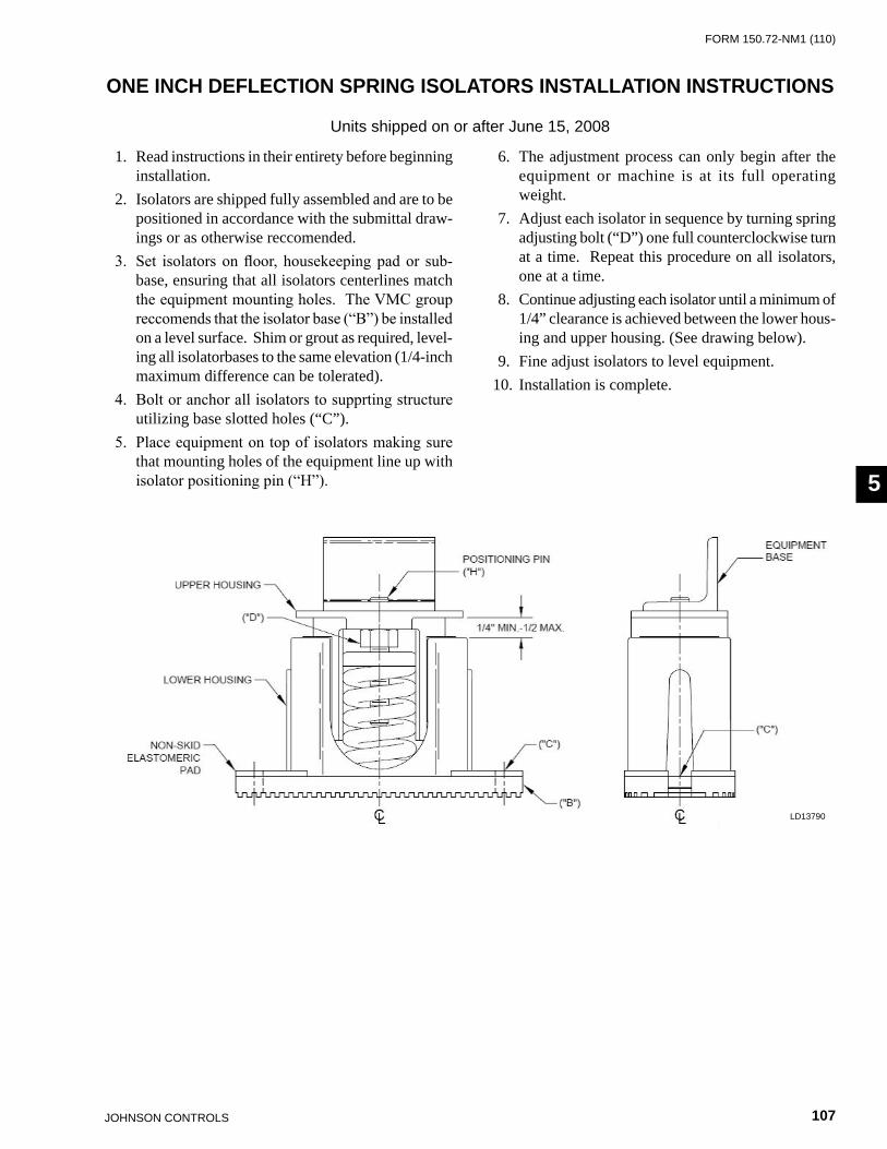
FORm 150.72-nm1 (110)
107JOHnSOn COnTROLS
55
ONE INCH DEFLECTION SPRING ISOLATORS INSTALLATION INSTRUCTIONS
Units shipped on or after June 15, 2008
1. Read instructions in their entirety before beginning installation.
2. Isolators are shipped fully assembled and are to be positioned in accordance with the submittal draw-ings or as otherwise reccomended.
3. Set isolators on floor, housekeeping pad or sub-base, ensuring that all isolators centerlines match the equipment mounting holes. The VMC group reccomends that the isolator base (“B”) be installed on a level surface. Shim or grout as required, level-ing all isolatorbases to the same elevation (1/4-inch maximum difference can be tolerated).
4. Bolt or anchor all isolators to supprting structure utilizing base slotted holes (“C”).
5. Place equipment on top of isolators making sure that mounting holes of the equipment line up with isolator positioning pin (“H”).
6. The adjustment process can only begin after the equipment or machine is at its full operating weight.
7. Adjust each isolator in sequence by turning spring adjusting bolt (“D”) one full counterclockwise turn at a time. Repeat this procedure on all isolators, one at a time.
8. Continue adjusting each isolator until a minimum of 1/4” clearance is achieved between the lower hous-ing and upper housing. (See drawing below).
9. Fine adjust isolators to level equipment.10. Installation is complete.
LD13790

JOHnSOn COnTROLS108
FORm 150.72-nm1 (110)Technical Data
SEISMIC ISOLATOR CROSS-REFERENCEUnits shipped on or after June 15, 2008
Y2RS
LD13761A
12"
5"
2-3/4"
12-1/4"
8-3/8"OPER.
HEIGHT
14"
5/8"
3/8"
Ø3/4"TYP.(4)
3-1/2"
5/8-11UNCTYP. (4)
2-3/4"
3/4"
7/8"
1-1/8"
3/8" GAP
5"
1/2" LIMITSTOP &NUT
NOTES:1. ALL DIMENSIONS ARE IN INCHES, INTERPRET PER ANSI Y14.2. STANDARD FINISH: HOUSING-POWDER COATED (COLOR:BLACK), SPRING-POWDER COATED (COLOR: SEE T
HARDWARE ZINC-ELECTROPLATE.3. EQUIPMENT MUST BE BOLTED OR WELDED TO THE TOP PLATE TO MEET ALLOWABLE SEISMIC RATINGS.4. ALL SPRINGS ARE DESIGNED FOR 50% OVERLOAD CAPACITY WITH EXCEPTION OF THE 2D-3280N & 2D-28705.6. CONSULT FACTORY FOR CONCRETE INSTALLATION.
REFER TO THE FOLLOWING PAGE FOR INSTALLATION INSTRUCTIONS.
Notes:1. All dimensions are in inches, interpret per ANSI
Y14.2. Standard finish: housing-powder coated (color,
black), spring-powder coated (color, see table below) hardware - zinc-electroplate.
3. Equipment must be bolted or welded to the top plate to meet allowable seismic ratings.
4. All springs are designed for 50% overload capacity with exception of the 2D-3280N and 2D-2870.
5. Refer to next page for installation instructions.6. Consult factory for concrete installation.
MODEL Y2RSI-2D SEISMICALLY RESTRAINED VIBRATION ISOLATOR FOR 2” DEFLECTION
SEISMIC MOUNT SIZE
RATED LOAD (LBS)
RATED DEFLECTION
(IN)
SPRING RATE (LBS/IN)
SOLID LOAD (LBS)
COLOR CODEALLOWABLE
G RATING HORIZONTAL
Y2RSI-2D-150 150 2.4 62 234 WHITE 34.7Y2RSI-2D-320 320 2.3 140 490 YELLOW 16.3Y2RSI-2D-460 460 2.3 200 688 GREEn 11.3Y2RSI-2D-710 710 2.2 330 1072 DK BROWn 7.3Y2RSI-2D-870 870 1.9 460 1312 RED 6
Y2RSI-2D-1200N 1200 1.9 638 1818 RED/BLACK 4.3Y2RSI-2D-1450 1450 1.8 900 2450 TAn 3.6Y2RSI-2D-1690 1690 1.7 1140 2892 PInK 3.1
Y2RSI-2D-2000N 2000 1.7 1318 3342 PInK/BLACK 2.6Y2RSI-2D-2640N 2640 1.5 1854 4283 PInK/GRAY 2
Y2RSI-2D-2870N 3080 1.5 2004 4629PInK/GRAY/
ORAnGE1.7
Y2RSI-2D-3280N 3740 1.8 2134 4930PInK/GRAY/DK
BROWn1.4
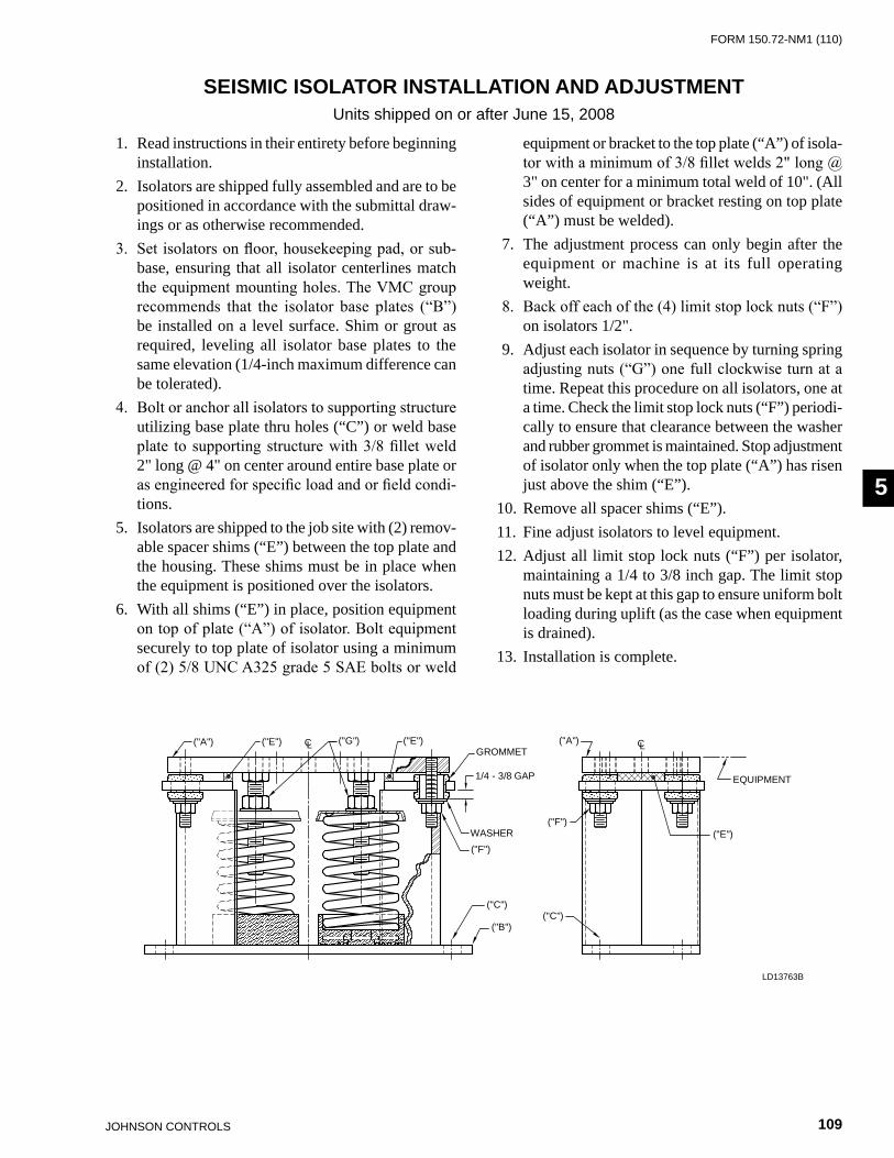
FORm 150.72-nm1 (110)
109JOHnSOn COnTROLS
55
SEISMIC ISOLATOR INSTALLATION AND ADJUSTMENTUnits shipped on or after June 15, 2008
1. Read instructions in their entirety before beginning installation.
2. Isolators are shipped fully assembled and are to be positioned in accordance with the submittal draw-ings or as otherwise recommended.
3. Set isolators on floor, housekeeping pad, or sub-base, ensuring that all isolator centerlines match the equipment mounting holes. The VMC group recommends that the isolator base plates (“B”) be installed on a level surface. Shim or grout as required, leveling all isolator base plates to the same elevation (1/4-inch maximum difference can be tolerated).
4. Bolt or anchor all isolators to supporting structure utilizing base plate thru holes (“C”) or weld base plate to supporting structure with 3/8 fillet weld 2" long @ 4" on center around entire base plate or as engineered for specific load and or field condi-tions.
5. Isolators are shipped to the job site with (2) remov-able spacer shims (“E”) between the top plate and the housing. These shims must be in place when the equipment is positioned over the isolators.
6. With all shims (“E”) in place, position equipment on top of plate (“A”) of isolator. Bolt equipment securely to top plate of isolator using a minimum of (2) 5/8 UNC A325 grade 5 SAE bolts or weld
equipment or bracket to the top plate (“A”) of isola-tor with a minimum of 3/8 fillet welds 2" long @ 3" on center for a minimum total weld of 10". (All sides of equipment or bracket resting on top plate (“A”) must be welded).
7. The adjustment process can only begin after the equipment or machine is at its full operating weight.
8. Back off each of the (4) limit stop lock nuts (“F”) on isolators 1/2".
9. Adjust each isolator in sequence by turning spring adjusting nuts (“G”) one full clockwise turn at a time. Repeat this procedure on all isolators, one at a time. Check the limit stop lock nuts (“F”) periodi-cally to ensure that clearance between the washer and rubber grommet is maintained. Stop adjustment of isolator only when the top plate (“A”) has risen just above the shim (“E”).
10. Remove all spacer shims (“E”).11. Fine adjust isolators to level equipment.12. Adjust all limit stop lock nuts (“F”) per isolator,
maintaining a 1/4 to 3/8 inch gap. The limit stop nuts must be kept at this gap to ensure uniform bolt loading during uplift (as the case when equipment is drained).
13. Installation is complete.
LD13763B
WASHER("F")
("B")
GROMMET("G") ("A")
("C")
("F")("E")
("E") ("E")
1/4 - 3/8 GAP
CLCL
("C")
EQUIPMENT
("A")
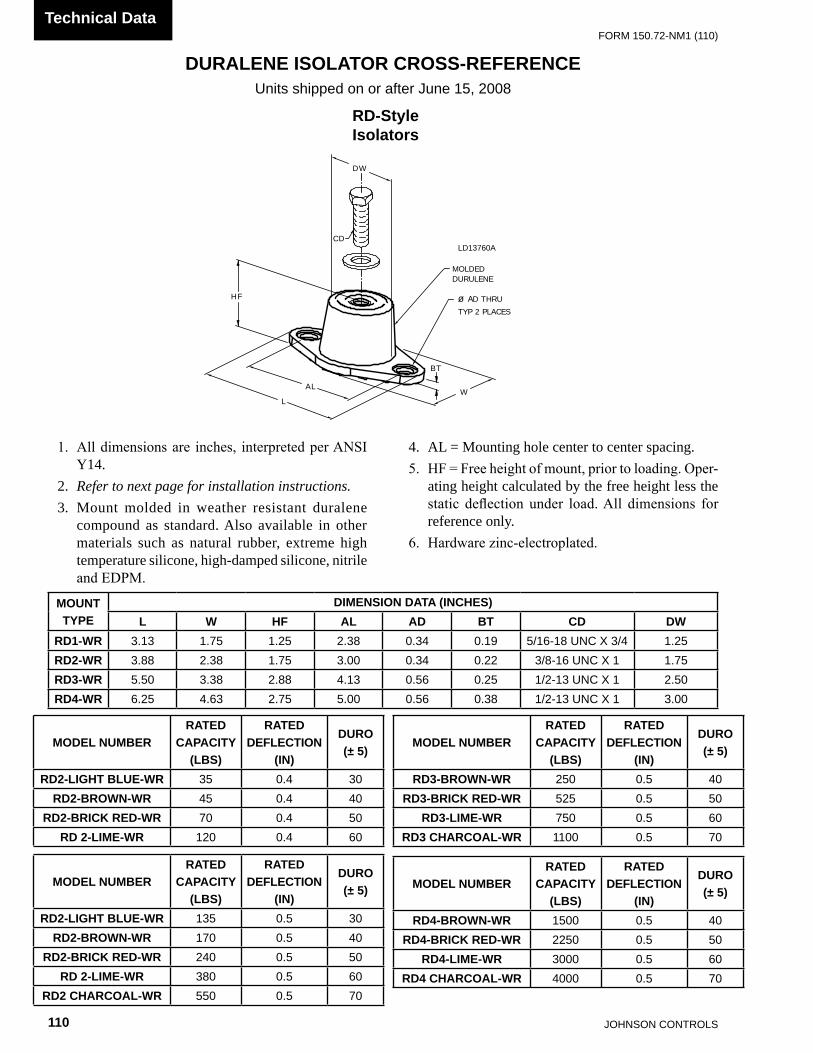
JOHnSOn COnTROLS110
FORm 150.72-nm1 (110)Technical Data
DURALENE ISOLATOR CROSS-REFERENCEUnits shipped on or after June 15, 2008
LD13760A
RD-Style Isolators
L
AL
DW
BT
HF ø AD THRUTYP 2 PLACES
MOLDEDDURULENE
CD
W
Notes:1. All dimensions are inches, interpreted per ANSI Y14.2. Refer to the folling Page for installation instructions.3. Mount molded in weather resistant duralene compound as standard. Also available in other materials such as natural rubber, extreme high temperature silicone, high-damped silicone, nitrile and EDPM.4. AL = Mounting hole center to center spacing.5. HF = Free height of mount, prior to loading. Operating height calculated by the free height less the static deflection under load. All dimensions for reference only.6. Hardware zinc-electroplated.
1. All dimensions are inches, interpreted per ANSI Y14.
2. Refer to next page for installation instructions.3. Mount molded in weather resistant duralene
compound as standard. Also available in other materials such as natural rubber, extreme high temperature silicone, high-damped silicone, nitrile and EDPM.
4. AL = Mounting hole center to center spacing.5. HF = Free height of mount, prior to loading. Oper-
ating height calculated by the free height less the static deflection under load. All dimensions for reference only.
6. Hardware zinc-electroplated.
MOUNT TYPE
DIMENSION DATA (INCHES)L W HF AL AD BT CD DW
RD1-WR 3.13 1.75 1.25 2.38 0.34 0.19 5/16-18 UnC X 3/4 1.25RD2-WR 3.88 2.38 1.75 3.00 0.34 0.22 3/8-16 UnC X 1 1.75RD3-WR 5.50 3.38 2.88 4.13 0.56 0.25 1/2-13 UnC X 1 2.50RD4-WR 6.25 4.63 2.75 5.00 0.56 0.38 1/2-13 UnC X 1 3.00
MODEL NUMBERRATED
CAPACITY (LBS)
RATED DEFLECTION
(IN)
DURO(± 5)
RD2-LIGHT BLUE-WR 35 0.4 30RD2-BROWN-WR 45 0.4 40
RD2-BRICK RED-WR 70 0.4 50RD 2-LIME-WR 120 0.4 60
MODEL NUMBERRATED
CAPACITY (LBS)
RATED DEFLECTION
(IN)
DURO(± 5)
RD3-BROWN-WR 250 0.5 40RD3-BRICK RED-WR 525 0.5 50
RD3-LIME-WR 750 0.5 60RD3 CHARCOAL-WR 1100 0.5 70
MODEL NUMBERRATED
CAPACITY (LBS)
RATED DEFLECTION
(IN)
DURO(± 5)
RD2-LIGHT BLUE-WR 135 0.5 30RD2-BROWN-WR 170 0.5 40
RD2-BRICK RED-WR 240 0.5 50RD 2-LIME-WR 380 0.5 60
RD2 CHARCOAL-WR 550 0.5 70
MODEL NUMBERRATED
CAPACITY (LBS)
RATED DEFLECTION
(IN)
DURO(± 5)
RD4-BROWN-WR 1500 0.5 40RD4-BRICK RED-WR 2250 0.5 50
RD4-LIME-WR 3000 0.5 60RD4 CHARCOAL-WR 4000 0.5 70

FORm 150.72-nm1 (110)
111JOHnSOn COnTROLS
55
INSTALLATION OF DURULENE VIBRATION ISOLATORS
Units shipped on or after June 15, 2008
LD13762B
D D
TOP BOLT
CLSECTION D-D
TOP WASHER
("A")
("B")
CL
("C")
("B")
1. Read instructions in their entirety before beginning installation.
2. Isolators are shipped fully assembled and are to be positioned in accordance with the submittal draw-ings or as otherwise recommended.
3. Set isolators on floor, housekeeping pad, or sub-base, ensuring that all isolator centerlines match the equipment mounting holes. The VMC group recom-mends that the isolator base (“A”) be installed on a level surface. Shim or grout as required, leveling
all isolator bases to the same elevation (1/32-inch maximum difference can be tolerated).
4. Bolt or anchor all isolators to supporting structure utilizing base thru holes (“B”).
5. Remove top bolt and top washer. Place equipment on top of isolators so that mounting holes in equip-ment or base line up with threaded hole (“C”).
6. Reinstall top bolt and washer and tighten down.7. Installation is complete.

JOHnSOn COnTROLS112
FORm 150.72-nm1 (110)Technical Data
ISOLATOR INFORMATION (For units shipped before June 15, 2008)
EE
EE
H
T
HCWW
LHCL
"D" Tap - 4 Holes unless otherwise requested
AdjustmentBolt
Vertical LimitStops-Out of
contact duringnormal operation
Non-Skid Neoprene Pad-Pad can be removed ifmounts are weldedinto position.
EnclosedSteelHousing
InternalNeopreneAcoustical
Pad
LowerRestrainingNut
RubberSnubbingCollar
MBD -MaxBoltDiameter
SLRS SEISMIC ISOLATOR SPECIFICATIONS
LD10509
NOTES: Illustration above shows a SLRS-4-C2 (4 Springs). SLRS-8-2 & C2 have one spring, and SLRS-2-C2 has two springs. SLRS-6-C2 has six springs and SLRS-9-C2 has nine springs.
* value is de-rated by 15%
PIN 54 = S
*Weight Range (lbs) *Weight Range (kg) Vendor P/N COLOR YORK P/N
UP TO 358 LBS Up to 162 kg SLRS-2-C2-420 Red 029-24585-006
358-442 LBS 162 to 201 kg SLRS-2-C2-520 White 029-24585-007
443-581 LBS 201 to 264 kg SLRS-2-C2-660 Black 029-24585-008
582-782 LBS 264 to 335 kg SLRS-2-C2-920 Blue 029-24585-009
783-1037 LBS 335 to 471 kg SLRS-2-C2-1220 Green 029-24585-010
1038-1496 LBS 471 to 679 kg SLRS-2-C2-1760 Gray 029-24585-011
1497-2057 LBS 679 to 933 kg SLRS-2-C2-2420 Silver 029-24585-012
2058-2618 LBS 933 to 1188 kg SLRS-2-C2-3080 Gray w/ Red 029-24585-013
2619-3179 LBS 1188 to 1442 kg SLRS-2-C2-3740 Silver w/ Red 029-24585-014

FORm 150.72-nm1 (110)
113JOHnSOn COnTROLS
55
SLRS SEISMIC ISOLATOR INSTALLATION AND ADJUSTMENT
To install and adjust mounts:1. Supports for mountings must be leveled to instal-
lation's acceptable tolerances.2. Mountings not subjected to seismic or wind forces
do not require bolting to supports.3. Mountings subjected to seismic or wind forces must
be bolted or welded in position.4. If mountings are welded in position, remove lower
friction pad before welding.5. Set mountings with top channels held in place by
the lower restraining nuts and limit stops.6. Place equipment on mountings and secure by bolt-
ing or welding.7. Hold lower restraining nut in place and turn verti-
cal limit stop bolt counter-clockwise until there
"D" Tap - 4 Holes unless otherwise requested
AdjustmentBolt
vertical LimitStops-Out of
contact duringnormal operation
non-Skid neoprene Pad-Pad can be removed ifmounts are weldedinto position.
EnclosedSteelHousing
InternalneopreneAcoustical
Pad
LowerRestrainingnut
RubberSnubbingCollar
mBD -maxBoltDiameter
SHIPPED & InSTALLED AFTER ADJUSTmEnT
1/4"
1/8"
LImIT STOP BOLT
LOWER RESTRAInInG BOLTS
LD10568
Units shipped before June 15, 2008
is a 1/8" gap between the bolt head and the steel washer.
8. Turn adjustment bolt 8 turns on each mount.9. Take one additional complete turn on each adjust-
ment bolt in sequence until the top plate lifts off of the lower restraining nuts. Take no additional turns on that mount. Continue with equal turns on the other mounts until the top plates lift off of the lower restraining nuts of all mounts.
10. Hold the limit stop bolt in place and turn the lower restraining nut clockwise and tighten it against the stanchion. Repeat the same procedure on all mounts.
11. Top plate should remain at a fixed elevation, plus or minus 1/8".

JOHnSOn COnTROLS114
FORm 150.72-nm1 (110)Technical Data
FOR UNITS WITH ALL POINT LOADS LESS THAN 1404 LBS (637 KG)Weight Range (lbs) Weight Range (kg) Model Number Color YORK P/N
239 to 384 lbs 108 to 174 kg CIP-B- Red 029-24583-002384 to 639 lbs 174 to 290 kg CIP-B- White 029-24583-003639 to 851 lbs 290 to 386 kg CIP-B- Blue 029-24583-004
851 to 1064 lbs 386 to 483 kg CIP-B- Gray 029-24583-0051064 to 1404 lbs 483 to 637 kg CIP-B- Black 029-24583-006
FOR UNITS WITH ANY POINT LOAD ABOVE 1404 LBS (637 KG)Weight Range (lbs) Weight Range (kg) Model Number Color YORK P/N
Up to 851 lbs Up to 386 kg CIP-C- Black 029-24583-007851 to 1149 lbs 386 to 521 kg CIP-C- Yellow 029-24583-0081149 to 1489 lbs 521 to 675 kg CIP-C- Red w/Black 029-24583-0091489 to 1786 lbs 675 to 910 kg CIP-C- Yellow w/ Red 029-24583-010
1786 to 2028 lbs 910 to 920 kg CIP-C- Green w/ Yellow 029-24583-011
2028 to 2254 lbs 920 to 1022 kg CIP-C- Red w/ Red 029-24583-0122254 to 2936 lbs 1022 to 1332 kg CIP-C- Green w/ Red 029-24583-013
CIP-X-
E
Illustration shows single spring CIP-B or CIP-C mount.
HCLSBC
Slot Width - SW HCW
MAX BOLTDIA. - MBD
BASE PLATE DIMENSIONS
NON-SKID NEOPRENEACOUSTICAL ISOLATION PAD(Bolting to floor is not necessary for indoor applications)
All springs have additionaltravel to solid equal to 50%of the rated deflection.
A
L
FREE &OPERATINGHEIGHT
TW
FERROUS HOUSING
SIDE ACCESS INTERNALADJUSTMENT BOLTTurn clockwise to loadspring and maintain Free& Operating Height.
Dowel Pin is 3/8" dia. forCIP-A & 1/2" thereafter
Mounting may beoperated 1/2" aboveFree & OperatingHeight.
NOTE-CIP Mounts are notto be used in seismic or wind loadapplications.
EQUIPMENT BASE
TYPE CIP DIMENSIONS (inches)†
†Casting dimensions may vary ±1/8"
Size A L T W SW HCL HCW MBD SBCFreeHt.
CIP-B 8 /4 /2 /16 8
CIP-C 6 /8 /16 /85
1 1 7
7
3
3/8 1
6 /4 3/5 /43
8 /87 /1692 /43
3 /21
/2/4
1
167
/2/4
1
311
/4/8
1
777
MinHt.
5 /4 1
6 /4 3
6
ONE INCH DEFLECTION SPRING ISOLATOR CROSS-REFERENCEUnits shipped before June 15, 2008
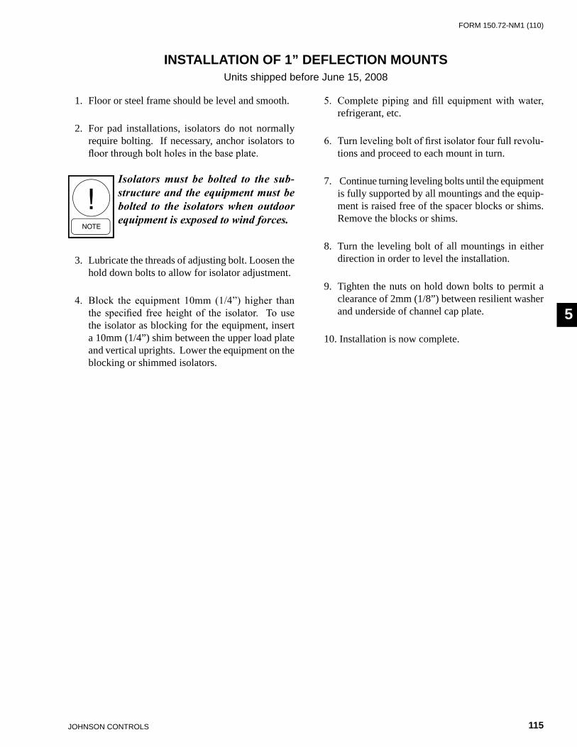
FORm 150.72-nm1 (110)
115JOHnSOn COnTROLS
55
1. Floor or steel frame should be level and smooth.
2. For pad installations, isolators do not normally require bolting. If necessary, anchor isolators to floor through bolt holes in the base plate.
Isolators must be bolted to the sub-structure and the equipment must be bolted to the isolators when outdoor equipment is exposed to wind forces.
3. Lubricate the threads of adjusting bolt. Loosen the hold down bolts to allow for isolator adjustment.
4. Block the equipment 10mm (1/4”) higher than the specified free height of the isolator. To use the isolator as blocking for the equipment, insert a 10mm (1/4”) shim between the upper load plate and vertical uprights. Lower the equipment on the blocking or shimmed isolators.
5. Complete piping and fill equipment with water, refrigerant, etc.
6. Turn leveling bolt of first isolator four full revolu-tions and proceed to each mount in turn.
7. Continue turning leveling bolts until the equipment is fully supported by all mountings and the equip-ment is raised free of the spacer blocks or shims. Remove the blocks or shims.
8. Turn the leveling bolt of all mountings in either direction in order to level the installation.
9. Tighten the nuts on hold down bolts to permit a clearance of 2mm (1/8”) between resilient washer and underside of channel cap plate.
10. Installation is now complete.
INSTALLATION OF 1” DEFLECTION MOUNTSUnits shipped before June 15, 2008

JOHnSOn COnTROLS116
FORm 150.72-nm1 (110)Technical Data
Weight Range (lbs) Weight Range (kg) Model Number Color YORK P/N
Up to 751 lbs Up to 341 kg nD-C Yellow 029-24584-001751 to 1651 lbs 341 to 749 kg nD-D Yellow 029-24584-002
1651 to 3226 lbs 749 to 1463 kg nD-DS Yellow 029-24584-004
"CS" Cap Screw
BC
"MBD" Max. Bolt Dia.Steel Plate - Top &Bottom Neoprenecovered to preventcorrosion
L
T
H
W
D
ENGLISH Size D H L T W BC CS MBDND-C 2-9/16 2-3/ 4 5-1/ 2 1/4 2-5/16 4-1/8 1/2-13 x 1 1/ 2ND-D 3-3/8 2-3/4 6-1/4 5/16 4 5 1/2-13 x 1 1/ 2
ND-DS 3-3/8 2-3/4 6-1/4 5/16 4 5 1/2-13 x 1 1/ 2
SIND-C 65.1 69.9 139.7 6.4 58.7 101.9 1/2- 13 x 1” 12.7ND-D 85.7 69.9 158.8 7.9 101.6 127.0 1/2- 13 x 1” 12.7
ND-DS 85.7 69.9 158.8 7.9 101.6 127.0 1/2- 13 x 1” 12.7
ND-X
(Inches)
(mm)
NEOPRENE ISOLATOR CROSS-REFERENCEUnits shipped before June 15, 2008

FORm 150.72-nm1 (110)
117JOHnSOn COnTROLS
55
ENGLISHSIZE H T D E L HCL W HCW MBD2-C2 8-1/2” 3/8” 5/8” 1-3/8” 14” 12-1/4” 5-1/4” 3-1/ 2” 5/8"
SISIZE H T D E L HCL W HCW MBD2-C2 215.9 9.5 15.9 34.9 355.6 311.2 133.4 88.9 5/8"
*Weight Range (lbs) Weight Range (kg) Model Number Color YORK P/N
Up to 358 lbs Up to 162 kg SLRS-2-C2- Red 029-24585-006358 to 443 lbs 162 to 201 kg SLRS-2-C2- White 029-24585-007443 to 582 lbs 201 to 264 kg SLRS-2-C2- Black 029-24585-008582 to 783 lbs 264 to 335 kg SLRS-2-C2- Blue 029-24585-009783 to 1038 lbs 335 to 471 kg SLRS-2-C2- Green 029-24585-0101038 to 1497 lbs 471 to 679 kg SLRS-2-C2- Gray 029-24585-0111497 to 2058 lbs 679 to 933 kg SLRS-2-C2- Silver 029-24585-0122058 to 2619 lbs 933 to 1188 kg SLRS-2-C2- Gray w/ red 029-24585-0132619 to 3180 lbs 1188 to 1442 kg SLRS-2-C2- Silver w/ red 029-24585-014
*value is de-rated by 15%
TWO INCH DEFLECTION, SEISMIC SPRING ISOLATOR CROSS-REFERENCE - SLRS
‡‡
‡‡
SLRS-2-C2 has 2 springs.
EE
EE
H
T
HCWW
LHCL
"D" Tap - 4 Holes unless otherwise requested
AdjustmentBolt
Vertical LimitStops-Out of
contact duringnormal operation
Non-Skid Neoprene Pad-Pad can be removed ifmounts are weldedinto position.
EnclosedSteelHousing
InternalNeopreneAcoustical
Pad
LowerRestrainingNut
RubberSnubbingCollar
MBD -MaxBoltDiameter
NOTES: Illustration above shows a SLRS-4-C2 (4 springs). SLRS-8-2 & C2 have 1 spring, and SLRS-2-C2 has two springs. SLRS-6-C2 has six springs and SLRS-9-C2 has nine springs.
Units shipped before June 15, 2008

JOHnSOn COnTROLS118
FORm 150.72-nm1 (110)Technical Data
SLRS SEISMIC ISOLATOR INSTALLATION AND ADJUSTMENT
To install and adjust mounts:1. Supports for mountings must be leveled to instal-
lation's acceptable tolerances.2. Mountings not subjected to seismic or wind forces
do not require bolting to supports.3. Mountings subjected to seismic or wind forces must
be bolted or welded in position.4. If mountings are welded in position, remove lower
friction pad before welding.5. Set mountings with top channels held in place by
the lower restraining nuts and limit stops.6. Place equipment on mountings and secure by bolt-
ing or welding.7. Hold lower restraining nut in place and turn verti-
cal limit stop bolt counter-clockwise until there
"D" Tap - 4 Holes unless otherwise requested
AdjustmentBolt
vertical LimitStops-Out of
contact duringnormal operation
non-Skid neoprene Pad-Pad can be removed ifmounts are weldedinto position.
EnclosedSteelHousing
InternalneopreneAcoustical
Pad
LowerRestrainingnut
RubberSnubbingCollar
mBD -maxBoltDiameter
SHIPPED & InSTALLED AFTER ADJUSTmEnT
1/4"
1/8"
LImIT STOP BOLT
LOWER RESTRAInInG BOLTS
LD10568
Units shipped before June 15, 2008
is a 1/8" gap between the bolt head and the steel washer.
8. Turn adjustment bolt 8 turns on each mount.9. Take one additional complete turn on each adjust-
ment bolt in sequence until the top plate lifts off of the lower restraining nuts. Take no additional turns on that mount. Continue with equal turns on the other mounts until the top plates lift off of the lower restraining nuts of all mounts.
10. Hold the limit stop bolt in place and turn the lower restraining nut clockwise and tighten it against the stanchion. Repeat the same procedure on all mounts.
11. Top plate should remain at a fixed elevation, plus or minus 1/8".
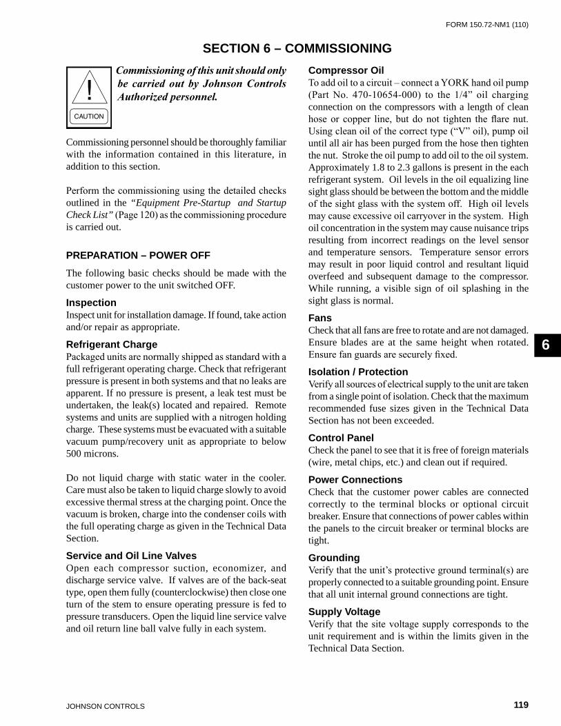
FORm 150.72-nm1 (110)
119JOHnSOn COnTROLS
6
Commissioning of this unit should only be carried out by Johnson Controls Authorized personnel.
Commissioning personnel should be thoroughly familiar with the information contained in this literature, in addition to this section.
Perform the commissioning using the detailed checks outlined in the “Equipment Pre-Startup and Startup Check List” (Page 120) as the commissioning procedure is carried out.
PREPARATION – POWER OFF
The following basic checks should be made with the customer power to the unit switched OFF.
Inspection Inspect unit for installation damage. If found, take action and/or repair as appropriate.
Refrigerant ChargePackaged units are normally shipped as standard with a full refrigerant operating charge. Check that refrigerant pressure is present in both systems and that no leaks are apparent. If no pressure is present, a leak test must be undertaken, the leak(s) located and repaired. Remote systems and units are supplied with a nitrogen holding charge. These systems must be evacuated with a suitable vacuum pump/recovery unit as appropriate to below 500 microns.
Do not liquid charge with static water in the cooler. Care must also be taken to liquid charge slowly to avoid excessive thermal stress at the charging point. Once the vacuum is broken, charge into the condenser coils with the full operating charge as given in the Technical Data Section.
Service and Oil Line ValvesOpen each compressor suction, economizer, and discharge service valve. If valves are of the back-seat type, open them fully (counterclockwise) then close one turn of the stem to ensure operating pressure is fed to pressure transducers. Open the liquid line service valve and oil return line ball valve fully in each system.
Compressor OilTo add oil to a circuit – connect a YORK hand oil pump (Part No. 470-10654-000) to the 1/4” oil charging connection on the compressors with a length of clean hose or copper line, but do not tighten the flare nut. Using clean oil of the correct type (“V” oil), pump oil until all air has been purged from the hose then tighten the nut. Stroke the oil pump to add oil to the oil system. Approximately 1.8 to 2.3 gallons is present in the each refrigerant system. Oil levels in the oil equalizing line sight glass should be between the bottom and the middle of the sight glass with the system off. High oil levels may cause excessive oil carryover in the system. High oil concentration in the system may cause nuisance trips resulting from incorrect readings on the level sensor and temperature sensors. Temperature sensor errors may result in poor liquid control and resultant liquid overfeed and subsequent damage to the compressor. While running, a visible sign of oil splashing in the sight glass is normal.
Fans Check that all fans are free to rotate and are not damaged. Ensure blades are at the same height when rotated. Ensure fan guards are securely fixed.
Isolation / ProtectionVerify all sources of electrical supply to the unit are taken from a single point of isolation. Check that the maximum recommended fuse sizes given in the Technical Data Section has not been exceeded.
Control PanelCheck the panel to see that it is free of foreign materials (wire, metal chips, etc.) and clean out if required.
Power ConnectionsCheck that the customer power cables are connected correctly to the terminal blocks or optional circuit breaker. Ensure that connections of power cables within the panels to the circuit breaker or terminal blocks are tight.
GroundingVerify that the unit’s protective ground terminal(s) are properly connected to a suitable grounding point. Ensure that all unit internal ground connections are tight.
Supply VoltageVerify that the site voltage supply corresponds to the unit requirement and is within the limits given in the Technical Data Section.
SECTION 6 – COMMISSIONING
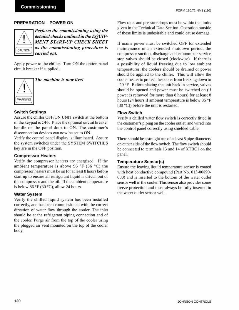
JOHnSOn COnTROLS120
FORm 150.72-nm1 (110)Commissioning
PREPARATION – POWER ON
Perform the commissioning using the detailed checks outlined in the EQUIP-MENT STARTUP CHECK SHEET as the commissioning procedure is carried out.
Apply power to the chiller. Turn ON the option panel circuit breaker if supplied.
The machine is now live!
Switch SettingsAssure the chiller OFF/ON UNIT switch at the bottom of the keypad is OFF. Place the optional circuit breaker handle on the panel door to ON. The customer’s disconnection devices can now be set to ON.Verify the control panel display is illuminated. Assure the system switches under the SYSTEM SWITCHES key are in the OFF position.
Compressor HeatersVerify the compressor heaters are energized. If the ambient temperature is above 96 °F (36 °C) the compressor heaters must be on for at least 8 hours before start-up to ensure all refrigerant liquid is driven out of the compressor and the oil. If the ambient temperature is below 86 °F (30 °C), allow 24 hours.
Water SystemVerify the chilled liquid system has been installed correctly, and has been commissioned with the correct direction of water flow through the cooler. The inlet should be at the refrigerant piping connection end of the cooler. Purge air from the top of the cooler using the plugged air vent mounted on the top of the cooler body.
Flow rates and pressure drops must be within the limits given in the Technical Data Section. Operation outside of these limits is undesirable and could cause damage.
If mains power must be switched OFF for extended maintenance or an extended shutdown period, the compressor suction, discharge and economizer service stop valves should be closed (clockwise). If there is a possibility of liquid freezing due to low ambient temperatures, the coolers should be drained or power should be applied to the chiller. This will allow the cooler heater to protect the cooler from freezing down to –20 °F. Before placing the unit back in service, valves should be opened and power must be switched on (if power is removed for more than 8 hours) for at least 8 hours (24 hours if ambient temperature is below 86 °F [30 °C]) before the unit is restarted.
Flow SwitchVerify a chilled water flow switch is correctly fitted in the customer’s piping on the cooler outlet, and wired into the control panel correctly using shielded cable.
There should be a straight run of at least 5 pipe diameters on either side of the flow switch. The flow switch should be connected to terminals 13 and 14 of XTBC1 on the panel.
Temperature Sensor(s)Ensure the leaving liquid temperature sensor is coated with heat conductive compound (Part No. 013-00890-000) and is inserted to the bottom of the water outlet sensor well in the cooler. This sensor also provides some freeze protection and must always be fully inserted in the water outlet sensor well.
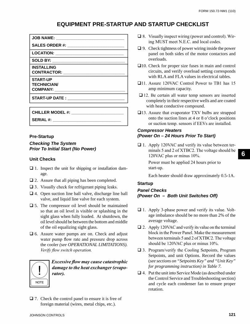
FORm 150.72-nm1 (110)
121JOHnSOn COnTROLS
6
JOB NAME: ______________________________
SALES ORDER #: _________________________
LOCATION: ______________________________
SOLD BY: ________________________________INSTALLINGCONTRACTOR: ___________________________
START-UP TECHNICIAN/ COMPANY: _______________________________
START-UP DATE : _________________________
CHILLER MODEL #: _______________________
SERIAL #: ______________________________
Pre-StartupChecking The System Prior To Initial Start (No Power)
Unit Checks
1. Inspect the unit for shipping or installation dam-age.
2. Assure that all piping has been completed. 3. Visually check for refrigerant piping leaks. 4. Open suction line ball valve, discharge line ball
valve, and liquid line valve for each system. 5. The compressor oil level should be maintained
so that an oil level is visible or splashing in the sight glass when fully loaded. At shutdown, the oil level should be between the bottom and middle of the oil equalizing sight glass.
6. Assure water pumps are on. Check and adjust water pump flow rate and pressure drop across the cooler (see OPERATIONAL LIMITATIONS). Verify flow switch operation.
Excessive flow may cause catastrophic damage to the heat exchanger (evapo-rator).
7. Check the control panel to ensure it is free of foreign material (wires, metal chips, etc.).
EQUIPMENT PRE-STARTUP AND STARTUP CHECKLIST
8. Visually inspect wiring (power and control). Wir-ing MUST meet N.E.C. and local codes.
9. Check tightness of power wiring inside the power panel on both sides of the motor contactors and overloads.
10. Check for proper size fuses in main and control circuits, and verify overload setting corresponds with RLA and FLA values in electrical tables.
11. Assure 120VAC Control Power to TB1 has 15 amp minimum capacity.
12. Be certain all water temp sensors are inserted completely in their respective wells and are coated with heat conductive compound.
13. Assure that evaporator TXV bulbs are strapped onto the suction lines at 4 or 8 o’clock positions or suction temp. sensors if EEVs are installed.
Compressor Heaters (Power On – 24 Hours Prior To Start)
1. Apply 120VAC and verify its value between ter-minals 5 and 2 of XTBC2. The voltage should be 120VAC plus or minus 10%.
Power must be applied 24 hours prior to start-up.
Each heater should draw approximately 0.5-1A.
StartupPanel Checks (Power On – Both Unit Switches Off)
1. Apply 3-phase power and verify its value. Volt-age imbalance should be no more than 2% of the average voltage.
2. Apply 120VAC and verify its value on the terminal block in the Power Panel. Make the measurement between terminals 5 and 2 of XTBC2. The voltage should be 120VAC plus or minus 10%.
3. Program/verify the Cooling Setpoints, Program Setpoints, and unit Options. Record the values (see sections on “Setpoints Key” and “Unit Key” for programming instruction) in Table 7.
4. Put the unit into Service Mode (as described under the Control Service and Troubleshooting section) and cycle each condenser fan to ensure proper rotation.
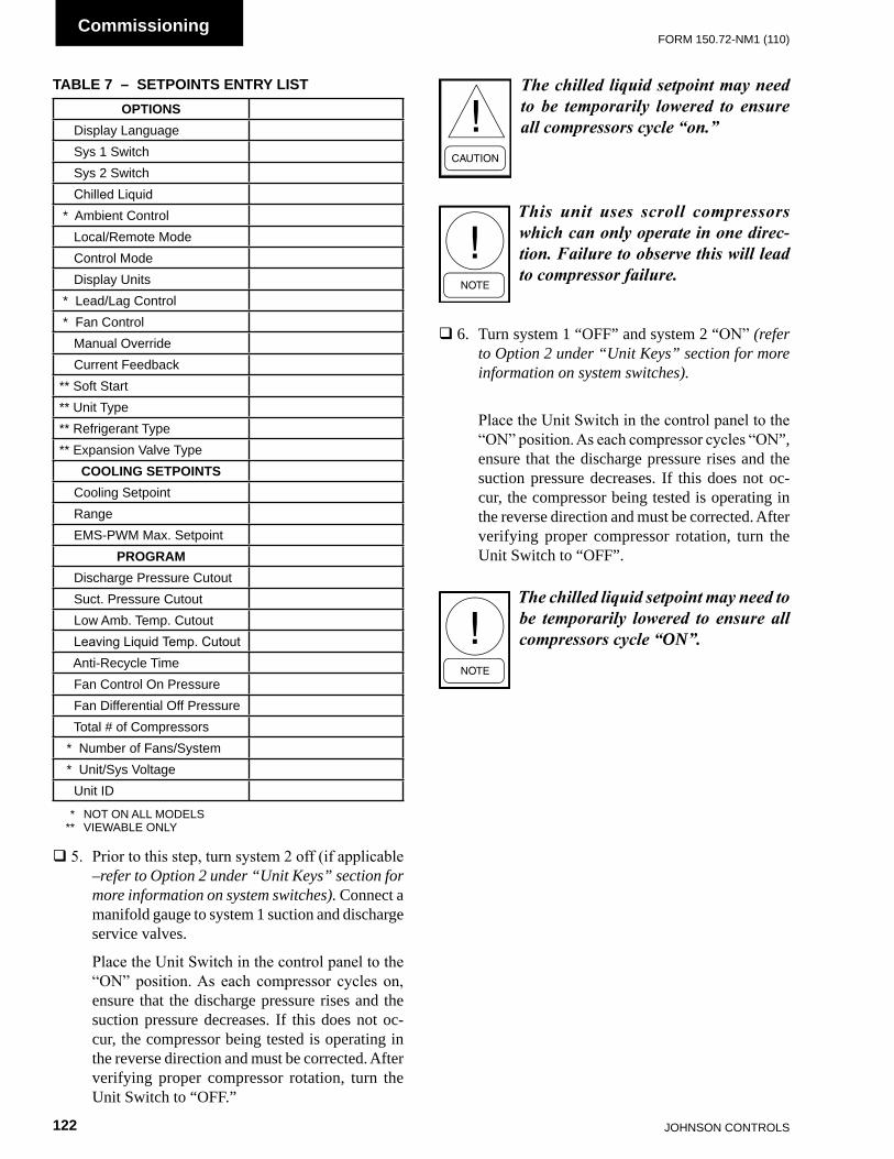
JOHnSOn COnTROLS122
FORm 150.72-nm1 (110)Commissioning
5. Prior to this step, turn system 2 off (if applicable –refer to Option 2 under “Unit Keys” section for more information on system switches). Connect a manifold gauge to system 1 suction and discharge service valves.
Place the Unit Switch in the control panel to the “ON” position. As each compressor cycles on, ensure that the discharge pressure rises and the suction pressure decreases. If this does not oc-cur, the compressor being tested is operating in the reverse direction and must be corrected. After verifying proper compressor rotation, turn the Unit Switch to “OFF.”
The chilled liquid setpoint may need to be temporarily lowered to ensure all compressors cycle “on.”
This unit uses scroll compressors which can only operate in one direc-tion. Failure to observe this will lead to compressor failure.
6. Turn system 1 “OFF” and system 2 “ON” (refer to Option 2 under “Unit Keys” section for more information on system switches).
Place the Unit Switch in the control panel to the “ON” position. As each compressor cycles “ON”, ensure that the discharge pressure rises and the suction pressure decreases. If this does not oc-cur, the compressor being tested is operating in the reverse direction and must be corrected. After verifying proper compressor rotation, turn the Unit Switch to “OFF”.
The chilled liquid setpoint may need to be temporarily lowered to ensure all compressors cycle “on”.
OPTIONS Display Language Sys 1 Switch Sys 2 Switch Chilled Liquid * Ambient Control Local/Remote mode Control mode Display Units * Lead/Lag Control * Fan Control manual Override Current Feedback** Soft Start** Unit Type** Refrigerant Type** Expansion valve Type
COOLING SETPOINTS Cooling Setpoint Range EmS-PWm max. Setpoint
PROGRAM Discharge Pressure Cutout Suct. Pressure Cutout Low Amb. Temp. Cutout Leaving Liquid Temp. Cutout Anti-Recycle Time Fan Control On Pressure Fan Differential Off Pressure Total # of Compressors * number of Fans/System * Unit/Sys voltage Unit ID
* nOT On ALL mODELS ** vIEWABLE OnLY
TABLE 7 – SETPOINTS ENTRY LIST

FORm 150.72-nm1 (110)
123JOHnSOn COnTROLS
6
CHECKING SUPERHEAT AND SUBCOOLING
The subcooling temperature of each system can be calculated by recording the temperature of the liquid line at the outlet of the condenser and subtracting it from the liquid line saturation temperature at the liquid stop valve (liquid line saturation temp. is converted from a temperature/pressure chart).Example: Liquid line pressure = 325 PSIG converted to temp. 101 °F minus liquid line temp. - 83 °F Subcooling = 18 °F
The subcooling should be adjusted to 18 °F at design conditions.
1. Record the liquid line pressure and its correspond-ing temperature, liquid line temperature and subcooling below:
SYS 1 SYS 2 Liq Line Press = _______ _______ PSIG Saturated Temp = _______ _______ °F Liq Line Temp = _______ _______ °F Subcooling = _______ _______ °F
After the subcooling is verified, the suction superheat should be checked. The superheat should be checked only after steady state operation of the chiller has been established, the leaving water temperature has been pulled down to the required leaving water temperature, and the unit is running in a fully loaded condition. Correct superheat setting for a system is 10 °F – 15 °F (5.56 °C – 8.33 °C) 18” (46 cm) from the heat exchanger.
Superheat should typically be set for no less than 10 °F with only a single compressor running on a circuit. The superheat is calculated as the difference between the actual temperature of the returned refrigerant gas in the
suction line entering the compressor and the temperature corresponding to the suction pressure as shown in a standard pressure/temperature chart.
Example: Suction Temp = 46 °F minus Suction Press 105 PSIG converted to Temp - 34 °F Superheat = 12 °F
When adjusting the expansion valve (TXV only), the adjusting screw should be turned not more than one turn at a time, allowing sufficient time (approximately 15 minutes) between adjustments for the system and the thermal expansion valve to respond and stabilize.
Assure that superheat is set at a minimum of 10 °F (5.56 °C) with a single compressor running on each circuit.
2. Record the suction temperature, suction pressure, suction saturation temperature, and superheat of each system below:
SYS 1 SYS 2 Suction Temp = _______ _______ °F Suction Pressure = _______ _______ PSIG Saturation Temp = _______ _______ °F Superheat = _______ _______ °F
LEAK CHECKING
1. Leak check compressors, fittings, and piping to ensure no leaks.
If the unit is functioning satisfactorily during the initial operating period, no safeties trip and the compressors cycle to control water temperature to setpoint, the chiller is ready to be placed into operation.
JOHnSOn COnTROLS124
FORm 150.72-nm1 (110)Commissioning
The operating sequence described below relates to operation on a hot water start after power has been applied, such as start-up commissioning. When a compressor starts, internal timers limit the minimum time before another compressor can start to 1 minute.
1. For the chiller system to run, the Flow Switch must be closed, any remote cycling contacts must be closed, the Daily Schedule must not be scheduling the chiller off, and temperature demand must be present.
2. When power is applied to the system, the micropro-cessor will start a 2 minute timer. This is the same timer that prevents an instantaneous start after a power failure.
3. At the end of the 2 minute timer, the microproces-sor will check for cooling demand. If all conditions allow for start, a compressor on the lead system will start and the liquid line solenoid will open. Coincident with the start, the anti-coincident timer will be set and begin counting downward from “60” seconds to “0” seconds.
If the unit is programmed for Auto Lead/Lag, the system with the shortest average run-time of the compressors will be assigned as the “lead” system. A new lead/lag assignment is made whenever all systems shut down.
4. Several seconds after the compressor starts, that systems first condenser fan will be cycled on (out-door air temperature is more than 25 °F (-4 °C) or discharge pressure). See the section on Operating Controls for details concerning condenser fan cycling.
5. After 1 minute of compressor run time, the next compressor in sequence will start when a system has to load. Additional compressors will be started at 60 second intervals as needed to satisfy tempera-ture setpoint.
6. If demand requires, the lag system will cycle on with the same timing sequences as the lead system after the lead system has run for five min-utes. Refer to the section on Capacity Control for a detailed explanation of system and compressor staging.
7. As the load decreases below setpoint, the compres-sors will be shut down in sequence. This will occur at intervals of either 60, 30, or 20 seconds based on water temperature as compared to setpoint, and control mode. See the section on Capacity Control for a detailed explanation.
8. When the last compressor in a “system” (two or three compressors per system), is to be cycled off, the system will initiate a pump-down. Each “system” has a pump-down feature upon shut-off. On a non-safety, non-unit switch shutdown, the LLSV will be turned off and the last compressor will be allowed to run until the suction pressure falls below the suction pressure cutout or for 180 seconds, whichever comes first.
UNIT OPERATING SEQUENCE

FORm 150.72-nm1 (110)
125JOHnSOn COnTROLS
7
SECTION 7 – UNIT CONTROLSYORK MILLENNIUM CONTROL CENTER
The YORK MicroComputer Control Center is a microprocessor based control system designed to provide the entire control for the liquid chiller. The control logic embedded in the microprocessor based control system will provide control for the chilled liquid temperatures, as well as sequencing, system safeties, displaying status, and daily schedules. The MicroComputer Control Center consists of four basic components:
1. IPU II and I/O Boards2. Transformer3. Display4. Keypad
The keypad allows programming and accessing setpoints, pressures, temperatures, cutouts, daily schedule, options, and fault information.
Remote cycling, demand limiting and chilled liquid temperature reset can be accomplished by field supplied contacts.
Compressor starting/stopping and loading/unloading decisions are performed by the Microprocessor to maintain leaving or return chilled liquid temperature. These decisions are a function of temperature deviation from setpoint.
A Master ON/Off switch is available to activate or deactivate the unit.
INTRODUCTION IPU II AND I/O BOARDS
The IPU and I/O boards are assembled to function as a single microprocessor controller requiring no additional hardware. The IPU II board contains a coldfire microprocessor and is the controller and decision maker in the control panel. The I/O board handles all of the chiller I/O (Inputs and Outputs). System inputs from pressure transducers and temperature sensors are connected to the I/O board. The I/O board contains a processor capable of reading the inputs and controlling the outputs. It communicates through the transition header with the IPU II microprocessor.
The I/O board circuitry multiplexes the analog inputs, digitizes them, and constantly scans them to keep watch on the chiller operating conditions. The input values are transmitted serially to the IPU II microprocessor board. From this information, the IPU II then issues commands to the I/O board relay outputs to control contactors, solenoids, etc. for Chilled Liquid Temperature Control and to react to safety conditions. The I/O board converts logic signals to operate relay outputs to 115 VAC levels used by motor contactors, fan contactors, solenoid valves, etc. to control system operation. The low voltage side of all relay coils on the I/O board are powered by +12V.
Keypad commands are actuated upon by the microprocessor to change setpoints, cutouts, scheduling, operating requirements, and to provide displays. The keypad and display are connected to the I/O board.
LD13283

JOHnSOn COnTROLS126
FORm 150.72-nm1 (110)Unit Controls
The on-board power supply converts 24 VAC from 75 VA, 120/24 VAC 50/60Hz UL listed class 2 power transformer to +12V, +5V and +3.3V using switching and linear voltage regulators located on the I/O and IPU II boards. These voltages are used to operate integrated circuitry on the board. The 40 character display and unit sensors (transducers and temp sensors) are supplied power for the microprocessor board +5V supply. 24V AC is rectified, but not regulated, to provide unregulated +30 VDC to supply all of the digital inputs.
The IPU II board contains one green “Power” LED to indicate that the board is powered up and one red “Status” LED to indicate by blinking that the processor is operating.
The I/O board contains one green “Power” LED to indicate that the board is powered up and one red “Status” LED to indicate by blinking that the processor is operating. The I/O board also contains two sets of Receiver/Transmit LED’s, one for each available serial communication port. The receive LED’s are green, and the Transmit LED’s are red.
A jumper on the I/O board selects 4 to 20mA or 0 to 10 VDC as the input type on the remote temperature reset analog input.
TRANSFORMER
A 75 VA, 120/24VAC 50/60Hz transformer is provided to supply power to the Microprocessor Board, which in turn rectifies, filters, and regulates as necessary to supply power to the display, sensors, and transducers.
DISPLAY
The 40 Character Display (2 lines of 20 characters) is a liquid crystal display used for displaying system parameters and operator messages.
The display in conjunction with the keypad, allows the operator to display system operating parameters as well as access programmed information already in memory. The display has a lighted background for night viewing and for viewing in direct sunlight.
When a key is pressed, such as the OPER DATA key, system parameters will be displayed and will remain on the display until another key is pressed. The system parameters can be scrolled with the use of the ↑ (UP) and ↓ (DOWN) arrow keys. The display will update all information at a rate of about 1 a second.
Display Messages may show characters indicating “greater than” (>) or “less than” (<). These characters indicate the actual values are greater than or less than the limit values which are being displayed.
KEYPAD
The 12 button non-tactile keypad allows the user to retrieve vitals system parameters such as system pressures, temperatures, compressor running times and starts, option information on the chiller, and system setpoints. This data is useful for monitoring chiller operation, diagnosing potential problems, troubleshooting, and commissioning the chiller.
It is essential the user become familiar with the use of the keypad and display. This will allow the user to make full use of the capabilities and diagnostic features available.
UNIT SWITCH
A unit ON/OFF switch is just underneath the keypad. This switch allows the operator to turn the entire unit “OFF” if desired. The switch must be placed in the “ON” position for the chiller to operate.
BATTERY BACK-UP
The IPU II contains a Real Time Clock integrated circuit chip with an internal battery backup. The purpose of this battery backup is to assure any programmed values (setpoints, clock, cutouts, etc.) are not lost during a power failure regardless of the time involved in a power cut or shutdown period.
PROGRAMMING # OF COMPRESSORS
The total number of compressors is programmable under the PROGRAM key. Dual (2) system chillers can have 4, 5, or 6 compressors.
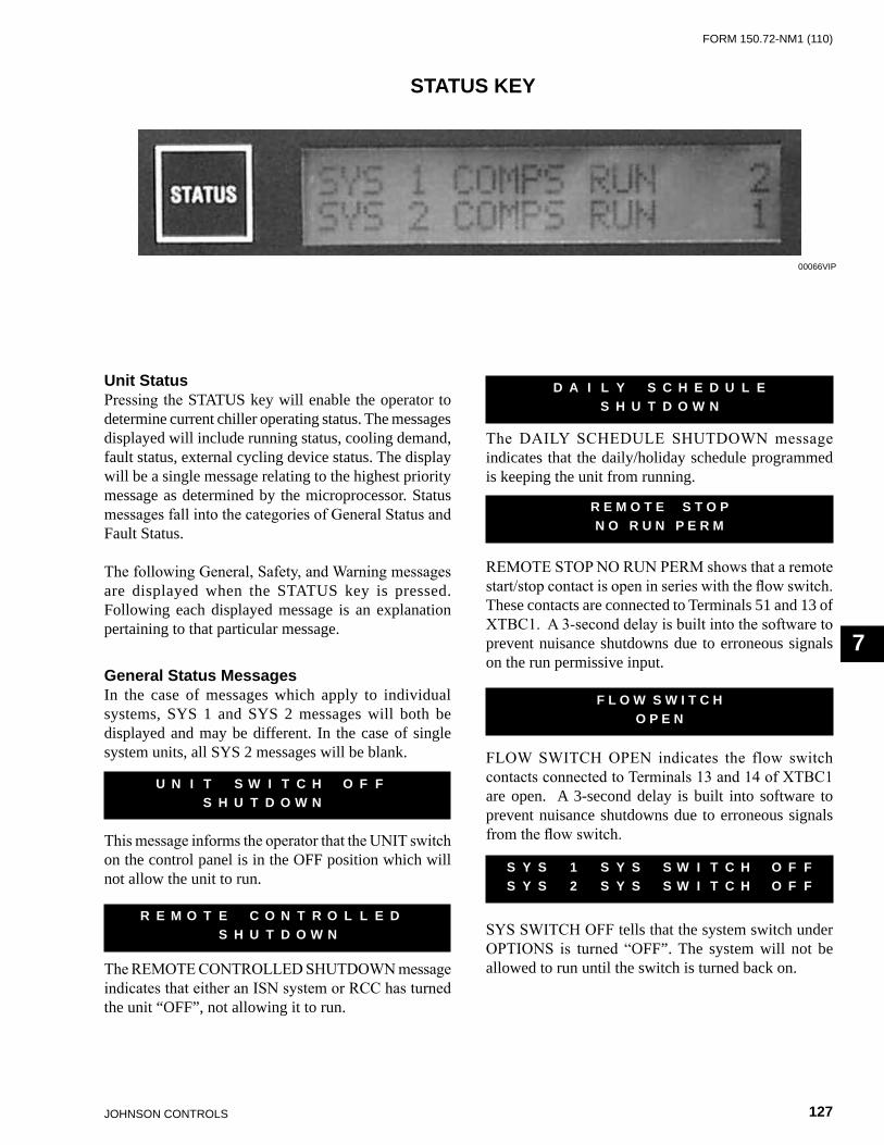
FORm 150.72-nm1 (110)
127JOHnSOn COnTROLS
7
STATUS KEY
Unit StatusPressing the STATUS key will enable the operator to determine current chiller operating status. The messages displayed will include running status, cooling demand, fault status, external cycling device status. The display will be a single message relating to the highest priority message as determined by the microprocessor. Status messages fall into the categories of General Status and Fault Status.
The following General, Safety, and Warning messages are displayed when the STATUS key is pressed. Following each displayed message is an explanation pertaining to that particular message.
General Status MessagesIn the case of messages which apply to individual systems, SYS 1 and SYS 2 messages will both be displayed and may be different. In the case of single system units, all SYS 2 messages will be blank.
This message informs the operator that the UNIT switch on the control panel is in the OFF position which will not allow the unit to run.
The REMOTE CONTROLLED SHUTDOWN message indicates that either an ISN system or RCC has turned the unit “OFF”, not allowing it to run.
U N I T S W I T C H O F F S H U T D O W N
R E M O T E C O N T R O L L E D S H U T D O W N
The DAILY SCHEDULE SHUTDOWN message indicates that the daily/holiday schedule programmed is keeping the unit from running.
REMOTE STOP NO RUN PERM shows that a remote start/stop contact is open in series with the flow switch. These contacts are connected to Terminals 51 and 13 of XTBC1. A 3-second delay is built into the software to prevent nuisance shutdowns due to erroneous signals on the run permissive input.
FLOW SWITCH OPEN indicates the flow switch contacts connected to Terminals 13 and 14 of XTBC1 are open. A 3-second delay is built into software to prevent nuisance shutdowns due to erroneous signals from the flow switch.
SYS SWITCH OFF tells that the system switch under OPTIONS is turned “OFF”. The system will not be allowed to run until the switch is turned back on.
D A I L Y S C H E D U L E S H U T D O W N
R E M O T E S T O PN O R U N P E R M
F L O W S W I T C H O P E N
S Y S 1 S Y S S W I T C H O F F S Y S 2 S Y S S W I T C H O F F
00066vIP
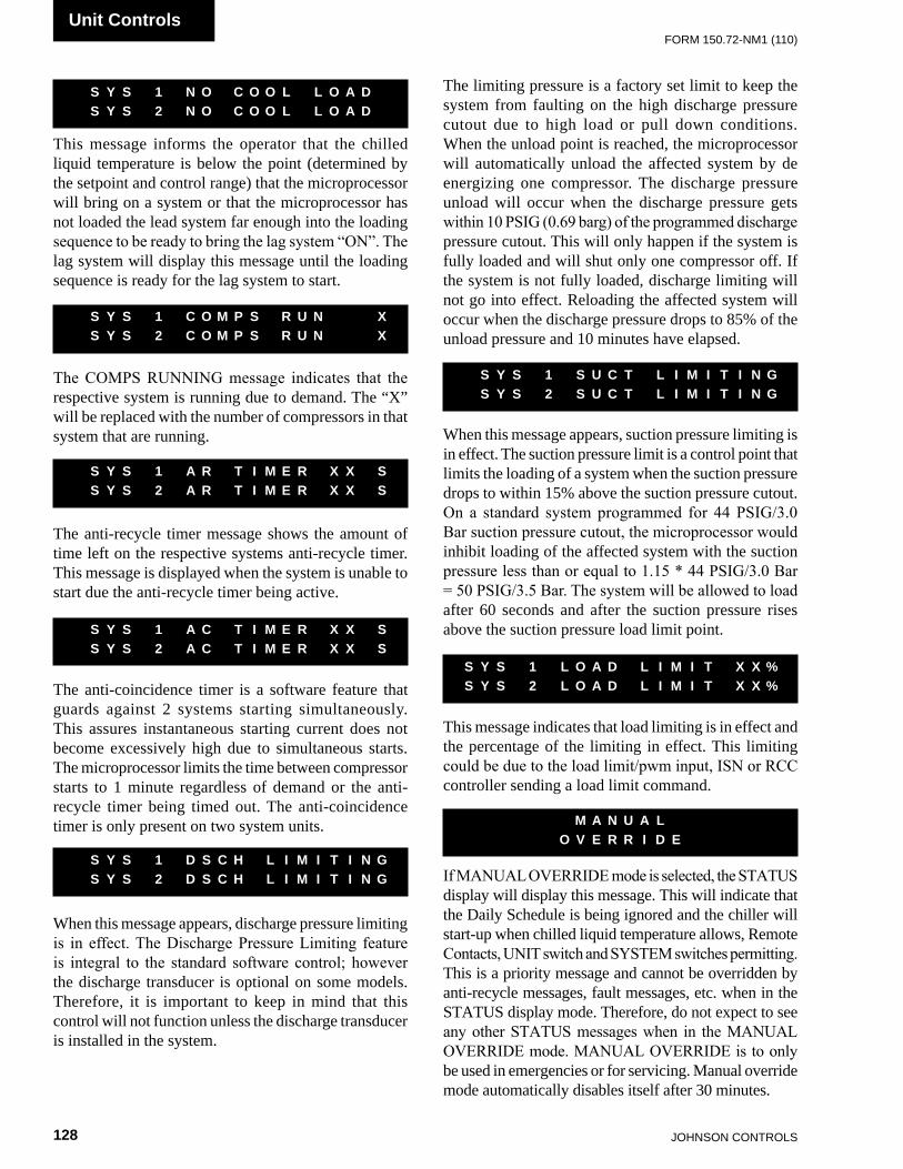
JOHnSOn COnTROLS128
FORm 150.72-nm1 (110)Unit Controls
This message informs the operator that the chilled liquid temperature is below the point (determined by the setpoint and control range) that the microprocessor will bring on a system or that the microprocessor has not loaded the lead system far enough into the loading sequence to be ready to bring the lag system “ON”. The lag system will display this message until the loading sequence is ready for the lag system to start.
The COMPS RUNNING message indicates that the respective system is running due to demand. The “X” will be replaced with the number of compressors in that system that are running.
The anti-recycle timer message shows the amount of time left on the respective systems anti-recycle timer. This message is displayed when the system is unable to start due the anti-recycle timer being active.
The anti-coincidence timer is a software feature that guards against 2 systems starting simultaneously. This assures instantaneous starting current does not become excessively high due to simultaneous starts. The microprocessor limits the time between compressor starts to 1 minute regardless of demand or the anti-recycle timer being timed out. The anti-coincidence timer is only present on two system units.
`
When this message appears, discharge pressure limiting is in effect. The Discharge Pressure Limiting feature is integral to the standard software control; however the discharge transducer is optional on some models. Therefore, it is important to keep in mind that this control will not function unless the discharge transducer is installed in the system.
S Y S 1 N O C O O L L O A D S Y S 2 N O C O O L L O A D
S Y S 1 C O M P S R U N X S Y S 2 C O M P S R U N X
S Y S 1 A R T I M E R X X S S Y S 2 A R T I M E R X X S
S Y S 1 A C T I M E R X X S S Y S 2 A C T I M E R X X S
S Y S 1 D S C H L I M I T I N G S Y S 2 D S C H L I M I T I N G
The limiting pressure is a factory set limit to keep the system from faulting on the high discharge pressure cutout due to high load or pull down conditions. When the unload point is reached, the microprocessor will automatically unload the affected system by de energizing one compressor. The discharge pressure unload will occur when the discharge pressure gets within 10 PSIG (0.69 barg) of the programmed discharge pressure cutout. This will only happen if the system is fully loaded and will shut only one compressor off. If the system is not fully loaded, discharge limiting will not go into effect. Reloading the affected system will occur when the discharge pressure drops to 85% of the unload pressure and 10 minutes have elapsed.
`
When this message appears, suction pressure limiting is in effect. The suction pressure limit is a control point that limits the loading of a system when the suction pressure drops to within 15% above the suction pressure cutout. On a standard system programmed for 44 PSIG/3.0 Bar suction pressure cutout, the microprocessor would inhibit loading of the affected system with the suction pressure less than or equal to 1.15 * 44 PSIG/3.0 Bar = 50 PSIG/3.5 Bar. The system will be allowed to load after 60 seconds and after the suction pressure rises above the suction pressure load limit point.
`
This message indicates that load limiting is in effect and the percentage of the limiting in effect. This limiting could be due to the load limit/pwm input, ISN or RCC controller sending a load limit command.
If MANUAL OVERRIDE mode is selected, the STATUS display will display this message. This will indicate that the Daily Schedule is being ignored and the chiller will start-up when chilled liquid temperature allows, Remote Contacts, UNIT switch and SYSTEM switches permitting. This is a priority message and cannot be overridden by anti-recycle messages, fault messages, etc. when in the STATUS display mode. Therefore, do not expect to see any other STATUS messages when in the MANUAL OVERRIDE mode. MANUAL OVERRIDE is to only be used in emergencies or for servicing. Manual override mode automatically disables itself after 30 minutes.
S Y S 1 S U C T L I M I T I N G S Y S 2 S U C T L I M I T I N G
S Y S 1 L O A D L I M I T X X % S Y S 2 L O A D L I M I T X X %
M A N U A L O V E R R I D E
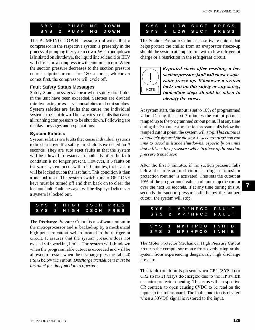
FORm 150.72-nm1 (110)
129JOHnSOn COnTROLS
7
The Suction Pressure Cutout is a software cutout that helps protect the chiller from an evaporator freeze-up should the system attempt to run with a low refrigerant charge or a restriction in the refrigerant circuit.
Repeated starts after resetting a low suction pressure fault will cause evapo-rator freezeup. Whenever a system locks out on this safety or any safety, immediate steps should be taken to identify the cause.
At system start, the cutout is set to 10% of programmed value. During the next 3 minutes the cutout point is ramped up to the programmed cutout point. If at any time during this 3 minutes the suction pressure falls below the ramped cutout point, the system will stop. This cutout is completely ignored for the first 30 seconds of system run time to avoid nuisance shutdowns, especially on units that utilize a low pressure switch in place of the suction pressure transducer.
After the first 3 minutes, if the suction pressure falls below the programmed cutout setting, a “transient protection routine” is activated. This sets the cutout at 10% of the programmed value and ramps up the cutout over the next 30 seconds. If at any time during this 30 seconds the suction pressure falls below the ramped cutout, the system will stop.
The Motor Protector/Mechanical High Pressure Cutout protects the compressor motor from overheating or the system from experiencing dangerously high discharge pressure.
This fault condition is present when CR1 (SYS 1) or CR2 (SYS 2) relays de-energize due to the HP switch or motor protector opening. This causes the respective CR contacts to open causing 0VDC to be read on the inputs to the microboard. The fault condition is cleared when a 30VDC signal is restored to the input.
S Y S 1 L O W S U C T P R E S S S Y S 2 L O W S U C T P R E S S
S Y S 1 M P / H P C O F A U L T S Y S 2 M P / H P C O F A U L T
S Y S 1 M P / H P C O I N H I B S Y S 2 M P / H P C O I N H I B
The PUMPING DOWN message indicates that a compressor in the respective system is presently in the process of pumping the system down. When pumpdown is initiated on shutdown, the liquid line solenoid or EEV will close and a compressor will continue to run. When the suction pressure decreases to the suction pressure cutout setpoint or runs for 180 seconds, whichever comes first, the compressor will cycle off.
Fault Safety Status MessagesSafety Status messages appear when safety thresholds in the unit have been exceeded. Safeties are divided into two categories – system safeties and unit safeties. System safeties are faults that cause the individual system to be shut down. Unit safeties are faults that cause all running compressors to be shut down. Following are display messages and explanations.
System SafetiesSystem safeties are faults that cause individual systems to be shut down if a safety threshold is exceeded for 3 seconds. They are auto reset faults in that the system will be allowed to restart automatically after the fault condition is no longer present. However, if 3 faults on the same system occur within 90 minutes, that system will be locked out on the last fault. This condition is then a manual reset. The system switch (under OPTIONS key) must be turned off and then back on to clear the lockout fault. Fault messages will be displayed whenever a system is locked out.
The Discharge Pressure Cutout is a software cutout in the microprocessor and is backed-up by a mechanical high pressure cutout switch located in the refrigerant circuit. It assures that the system pressure does not exceed safe working limits. The system will shutdown when the programmable cutout is exceeded and will be allowed to restart when the discharge pressure falls 40 PSIG below the cutout. Discharge transducers must be installed for this function to operate.
S Y S 1 P U M P I N G D O W N S Y S 2 P U M P I N G D O W N
S Y S 1 H I G H D S C H P R E S S Y S 2 H I G H D S C H P R E S

JOHnSOn COnTROLS130
FORm 150.72-nm1 (110)Unit Controls
After 30 minutes, the contacts will close and the system will be permitted to restart. The microprocessor will not try to restart the compressors in a system that shuts down on this safety for a period of 30 minutes to allow the internal compressor to time out.
During the 30 minute timeout, the MP/HPCO INHIB message will be displayed. The MP/HPCO fault will only be displayed after 3 shutdowns in 90 minutes, indicating the system is locked out and will not restart.
When the System Current Feedback option is installed and selected (Option 11 under OPTIONS key Current Feedback), this safety will operate as follows. If the actual feedback voltage of the system proportional to currents exceeds the programmed trip voltage for 5 seconds, the system will shutdown.
This safety will shut down a system if either suction temperature or suction pressure sensors read out of range high or low. This condition must be present for 3 seconds to cause a system shutdown. The safety locks out a system after the first fault and will not allow automatic restarting.
S Y S 1 H I G H M T R C U R R S Y S 2 H I G H M T R C U R R
The internal motor protector opens at 185 °F – 248 °F (85 °C – 120 °C) and auto resets. The mechanical HP switch opens at 585 PSIG plus or minus 10 PSIG (27.92 barg plus or minus .69 barg) and closes at 330 PSIG plus or minus 25 PSIG (22.75 barg plus or minus 1.72 barg).
The compressor is also equipped with a discharge temperature sensor for the purpose of sensing internal scroll temperature. This sensor protects the scrolls from overheating due to inadequate cooling that may occur when refrigerant charge is low, or superheat is too high.
When the sensor senses a high temperature, it opens the motor protector circuit in the compressor causing the compressor to shut down.
During the first two faults an MP/HP INHIBIT message will be displayed and the system will not be locked out. Only after the third fault in 90 minutes will the MP/HPCO FAULT message be displayed.
Whenever the motor protector or discharge sensor shuts down a compressor and the system, the internal compressor contacts will open for a period of 30 minutes to assure that the motor or scroll temperatures have time to dissipate the heat and cool down. The MP/HP INHIBIT message will be displayed while these contacts are open or when the HPCO is open. While this message is displayed, the compressors will not be permitted to start.
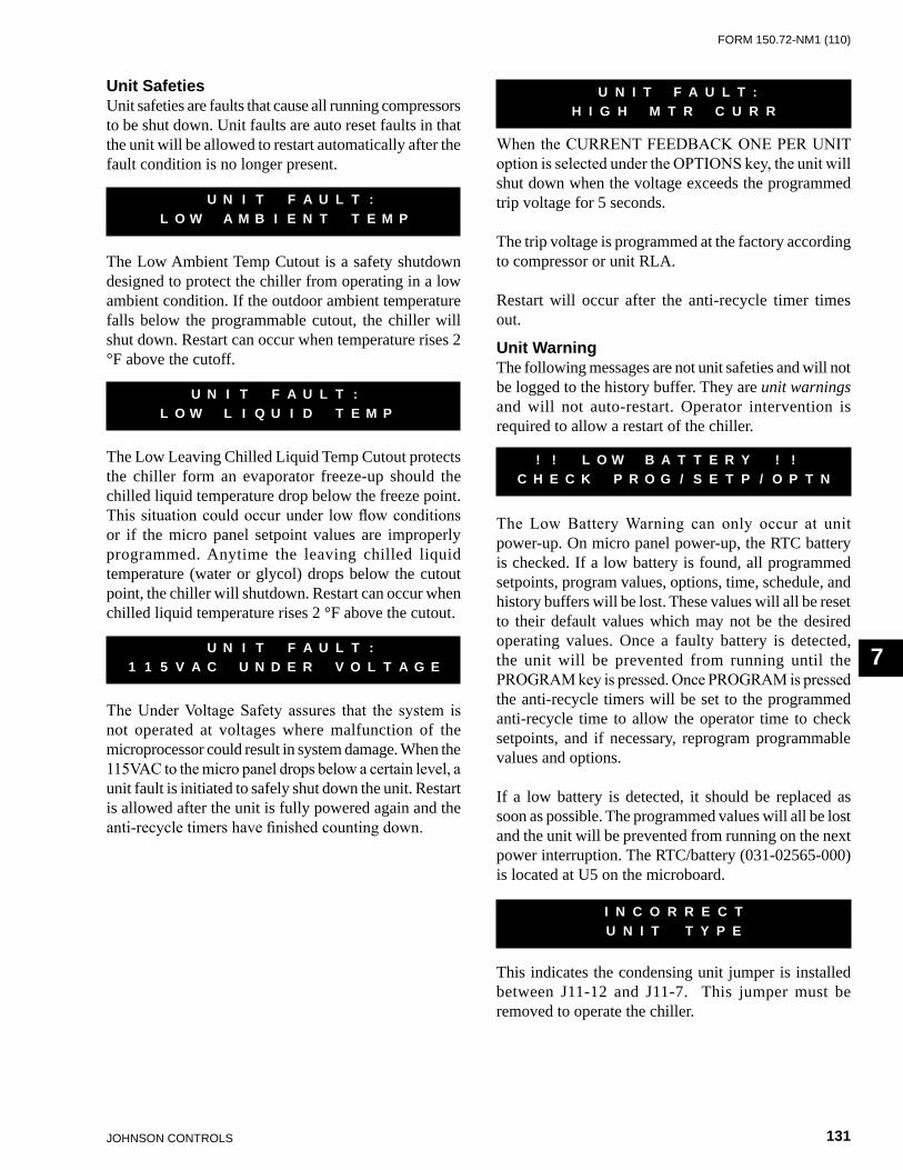
FORm 150.72-nm1 (110)
131JOHnSOn COnTROLS
7
Unit SafetiesUnit safeties are faults that cause all running compressors to be shut down. Unit faults are auto reset faults in that the unit will be allowed to restart automatically after the fault condition is no longer present.
The Low Ambient Temp Cutout is a safety shutdown designed to protect the chiller from operating in a low ambient condition. If the outdoor ambient temperature falls below the programmable cutout, the chiller will shut down. Restart can occur when temperature rises 2 °F above the cutoff.
The Low Leaving Chilled Liquid Temp Cutout protects the chiller form an evaporator freeze-up should the chilled liquid temperature drop below the freeze point. This situation could occur under low flow conditions or if the micro panel setpoint values are improperly programmed. Anytime the leaving chilled liquid temperature (water or glycol) drops below the cutout point, the chiller will shutdown. Restart can occur when chilled liquid temperature rises 2 °F above the cutout.
The Under Voltage Safety assures that the system is not operated at voltages where malfunction of the microprocessor could result in system damage. When the 115VAC to the micro panel drops below a certain level, a unit fault is initiated to safely shut down the unit. Restart is allowed after the unit is fully powered again and the anti-recycle timers have finished counting down.
U N I T F A U L T : L O W A M B I E N T T E M P
U N I T F A U L T : L O W L I Q U I D T E M P
U N I T F A U L T : 1 1 5 V A C U N D E R V O L T A G E
When the CURRENT FEEDBACK ONE PER UNIT option is selected under the OPTIONS key, the unit will shut down when the voltage exceeds the programmed trip voltage for 5 seconds.
The trip voltage is programmed at the factory according to compressor or unit RLA.
Restart will occur after the anti-recycle timer times out.
Unit WarningThe following messages are not unit safeties and will not be logged to the history buffer. They are unit warnings and will not auto-restart. Operator intervention is required to allow a restart of the chiller.
The Low Battery Warning can only occur at unit power-up. On micro panel power-up, the RTC battery is checked. If a low battery is found, all programmed setpoints, program values, options, time, schedule, and history buffers will be lost. These values will all be reset to their default values which may not be the desired operating values. Once a faulty battery is detected, the unit will be prevented from running until the PROGRAM key is pressed. Once PROGRAM is pressed the anti-recycle timers will be set to the programmed anti-recycle time to allow the operator time to check setpoints, and if necessary, reprogram programmable values and options.
If a low battery is detected, it should be replaced as soon as possible. The programmed values will all be lost and the unit will be prevented from running on the next power interruption. The RTC/battery (031-02565-000) is located at U5 on the microboard.
This indicates the condensing unit jumper is installed between J11-12 and J11-7. This jumper must be removed to operate the chiller.
U N I T F A U L T :H I G H M T R C U R R
! ! L O W B A T T E R Y ! ! C H E C K P R O G / S E T P / O P T N
I N C O R R E C T U N I T T Y P E
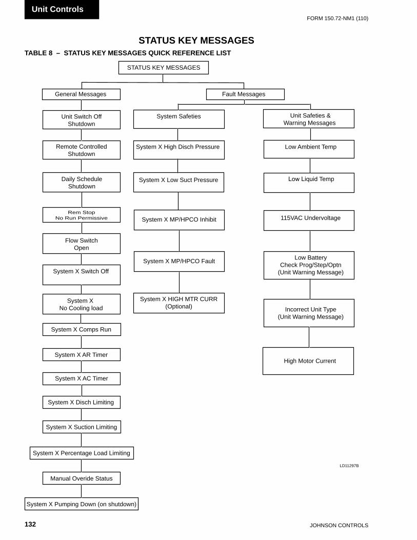
JOHnSOn COnTROLS132
FORm 150.72-nm1 (110)Unit Controls
STATUS KEY MESSAGESTABLE 8 – STATUS KEY MESSAGES QUICK REFERENCE LIST
LD11297B
STATUS KEY mESSAGES
General messages Fault messages
Unit Switch OffShutdown
Remote ControlledShutdown
Daily ScheduleShutdown
Unit Safeties &Warning messages
System Safeties
Low Ambient TempSystem X High Disch Pressure
System X Low Suct Pressure Low Liquid Temp
System X mP/HPCO Fault
115vAC Undervoltage
Low BatteryCheck Prog/Step/Optn
(Unit Warning message)
Rem Stopno Run Permissive
Flow SwitchOpen
Incorrect Unit Type(Unit Warning message)
High motor Current
System X Switch Off
System X Comps Run
System X AR Timer
System X AC Timer
System X Disch Limiting
System X Suction Limiting
System X Percentage Load Limiting
manual Overide Status
System X Pumping Down (on shutdown)
System X no Cooling load
System X HIGH mTR CURR(Optional)
System X mP/HPCO Inhibit
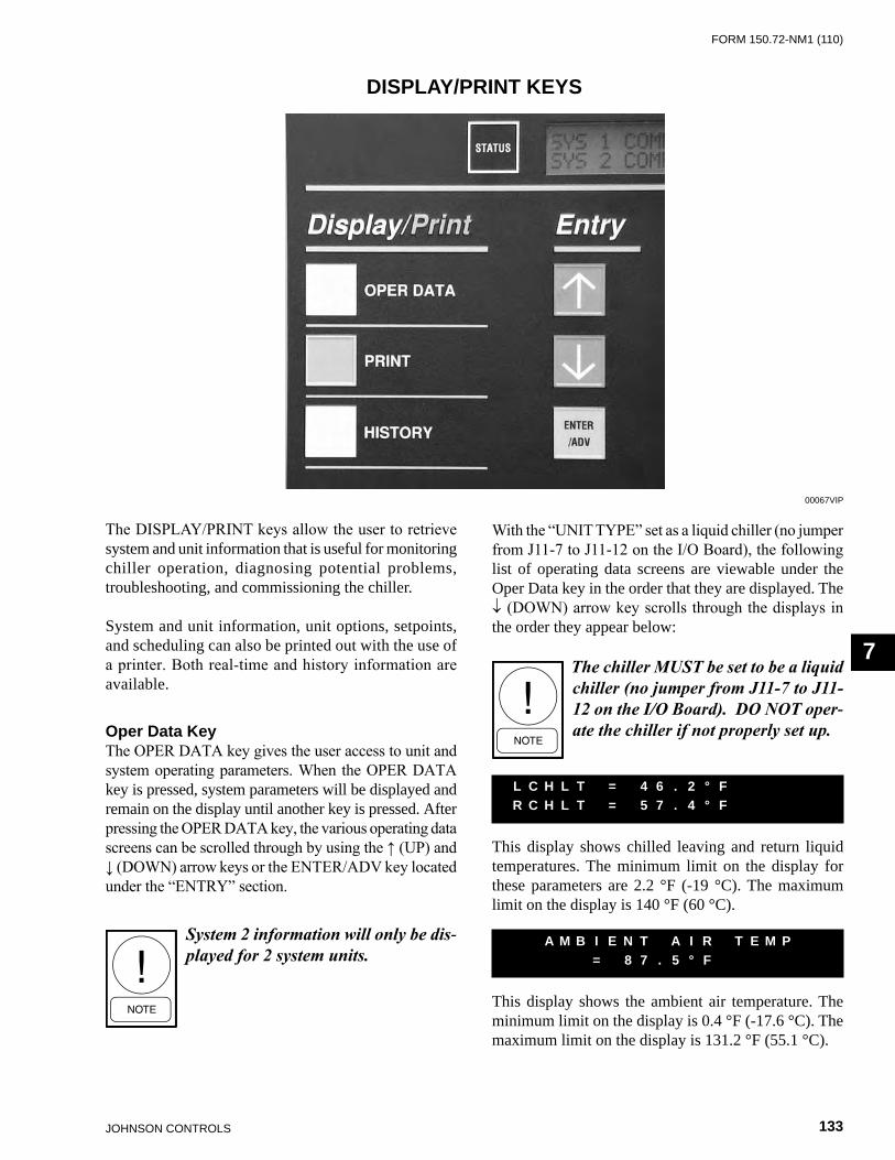
FORm 150.72-nm1 (110)
133JOHnSOn COnTROLS
7
The DISPLAY/PRINT keys allow the user to retrieve system and unit information that is useful for monitoring chiller operation, diagnosing potential problems, troubleshooting, and commissioning the chiller.
System and unit information, unit options, setpoints, and scheduling can also be printed out with the use of a printer. Both real-time and history information are available.
Oper Data KeyThe OPER DATA key gives the user access to unit and system operating parameters. When the OPER DATA key is pressed, system parameters will be displayed and remain on the display until another key is pressed. After pressing the OPER DATA key, the various operating data screens can be scrolled through by using the ↑ (UP) and ↓ (DOWN) arrow keys or the ENTER/ADV key located under the “ENTRY” section.
DISPLAY/PRINT KEYS
With the “UNIT TYPE” set as a liquid chiller (no jumper from J11-7 to J11-12 on the I/O Board), the following list of operating data screens are viewable under the Oper Data key in the order that they are displayed. The ↓ (DOWN) arrow key scrolls through the displays in the order they appear below:
The chiller MUST be set to be a liquid chiller (no jumper from J117 to J1112 on the I/O Board). DO NOT oper-ate the chiller if not properly set up.
This display shows chilled leaving and return liquid temperatures. The minimum limit on the display for these parameters are 2.2 °F (-19 °C). The maximum limit on the display is 140 °F (60 °C).
This display shows the ambient air temperature. The minimum limit on the display is 0.4 °F (-17.6 °C). The maximum limit on the display is 131.2 °F (55.1 °C).
L C H L T = 4 6 . 2 ° F R C H L T = 5 7 . 4 ° F °
A M B I E N T A I R T E M P = 8 7 . 5 ° F
00067vIP
System 2 information will only be dis-played for 2 system units.

JOHnSOn COnTROLS134
FORm 150.72-nm1 (110)Unit Controls
S Y S X S P = 7 2 . 1 P S I G D P = 2 2 7 . 0 P S I G
These displays show suction and discharge pressures for each system. The discharge pressure transducer is optional on some models.
If the optional discharge transducer is not installed, the discharge pressure would display 0 PSIG (0 barg).
The minimum limits for the display are:Suction Pressure: 0 PSIG (0 barg)Discharge Pressure: 0 PSIG (0 barg)
The maximum limits for the display are:Suction Pressure: 400 PSIG (27.58 barg)Discharge Pressure: 650 PSIG (44.82 barg)
The above two messages will appear sequentially for each system. The first display shows accumulated running hours of each compressor for the specific system. The second message shows the number of starts for each compressor on each system.
Run times and starts will only be dis-played for the actual number of sys-tems and compressors on the unit.
A total of 99,999 hours and starts can be logged before the counter rolls over to “0”.
This display of the load and unload timers indicate the time in seconds until the unit can load or unload. Whether the systems loads or unloads is determined by how far the actual liquid temperature is from setpoint. A detailed description of unit loading and unloading is covered under the topic of Capacity Control.
The display of COOLING DEMAND indicates the current “step” in the capacity control scheme when in Return Water Control Mode. The number of available steps are determined by how many compressors are in the unit. In the above display, the “2” does not mean that two compressor are running but only indicates that the capacity control scheme is on step 2 of 8. Capacity Control is covered in more detail in this publication which provides specific information on compressor staging (for Return Water Control only).
The COOLING DEMAND message will be replaced with this message when Leaving Chilled liquid control is selected. This message indicates the temperature error and the rate of change of the chilled liquid temperature.
This display indicates the current LEAD system. In this example system 2 is the LEAD system, making system 1 the LAG system. The LEAD system can be manually selected or automatic. Refer to the programming under the “Options” key. The Lead System display will only appear on a two system unit.
A unit utilizing hot gas bypass should be programmed for MANUAL with system 1 as the lead system. Failure to do so will prevent hot gas operation if system 2 switches to the lead system when programmed for AUTOMATIC LEAD/LAG.
S Y S X H O U R S 1 = X X X X X 2 = X X X X X, 3 = X X X X X
C O O L I N G D E M A N D 2 O F 8 S T E P S
L O A D T I M E R 5 8 S E C U N L O A D T I M E R 0 S E C
S Y S X S T A R T S 1 = X X X X X 2 = X X X X X, 3 = X X X X X
T E M P E R R O R X X X . X ° F T E M P R A T E X X X . X ° F / M
L E A D S Y S T E M I S S Y S T E M N U M B E R 2

FORm 150.72-nm1 (110)
135JOHnSOn COnTROLS
7
If the microprocessor is programmed for CURRENT FEEDBACK ONE PER UNIT under the OPTIONS key, the display will show up as the first display prior to the SYS 1 displays. Total chiller current is displayed as shown below:
If the microprocessor is programmed for CURRENT FEEDBACK NONE, no current display will appear.
The preceding five messages will appear sequentially, first for system 1, then for system 2.
The first message indicates the system and the associated compressors which are running.
The second message indicates the system run time in days – hours – minutes – seconds. Please note that this is not accumulated run time but pertains only to the current system cycle.
The third message indicates the system, and whether the liquid line solenoid or EEV pilot solenoid and hot gas solenoid are being turned on by the microboard. Please note that hot gas is not available for system 2, so there is no message pertaining to the hot gas solenoid when system 2 message is displayed.
The fourth message indicates the stage of condenser fan operation that is active.
See the section on Condenser Fan Control in the UNIT OPERATION section for more information.
U N I T A M P S = 5 4 . 0 V O L T S = 1 . 2
S Y S X R U N T I M E X X - X X - X X - X X D - H - M - S
S Y S X C O M P S T A T U S 1 = X X X 2 = X X X 3 = X X X
S Y S X L L S V I S O N H O T G A S S O L I S O F F
S Y S X A M P S = 3 6 . 0 V O L T S = 0 . 8
S Y S X F A N S T A G E 3
This display indicates the status of the evaporator heater. The evaporator heater is controlled by ambient air temperature. When the ambient temperature drops below 40 °F the heater is turned on. When the temperature rises above 45 °F the heater is turned off. An under voltage condition will keep the heater off until full voltage is restored to the system.
The evaporator pump contacts are energized when any compressor is running, or the unit is not OFF on the daily schedule and the unit switch is on, or the unit has shutdown on a Low Leaving Chilled Liquid fault. However, even if one of above is true, the pump will not run if the micro panel has been powered up for less than 30 seconds or if the pump has run in the last 30 seconds to prevent pump motor overheating. This contact supplies 115 VAC to the pump contactor.
The Evaporator Pump Total Run Hours display indicates the total pump run hours. Total hours continually increments similar to Compressor Run Hours. If dual pumps are fitted, run hours indicates total hours on both pumps.
There are several types of remote systems that can be used to control or monitor the unit. The following messages indicate the type of remote control mode active:
NONE – no remote control active. Remote monitoring may be via ISN.
ISN – YORK Talk via ISN allows remote load limiting and temperature reset through an ISN system.
LOAD LIM – Load limiting enabled using contact closure.
PWM TEMP – EMS temperature reset
E V A P O R A T O R H E A T E R S T A T U S I S = X X X
E V A P O R A T O R W A T E R P U M P S T A T U S = X X X X
E V A P P U M P T O T A L R U N H O U R S = X X X X X
A C T I V E R E M O T E C T R L N O N E
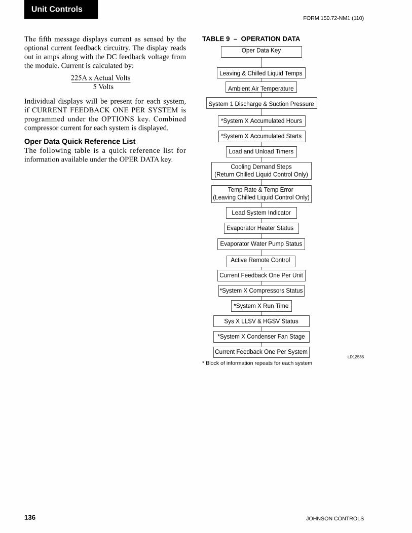
JOHnSOn COnTROLS136
FORm 150.72-nm1 (110)Unit Controls
TABLE 9 – OPERATION DATA
* Block of information repeats for each systemLD12585
The fifth message displays current as sensed by the optional current feedback circuitry. The display reads out in amps along with the DC feedback voltage from the module. Current is calculated by:
Individual displays will be present for each system, if CURRENT FEEDBACK ONE PER SYSTEM is programmed under the OPTIONS key. Combined compressor current for each system is displayed.
Oper Data Quick Reference ListThe following table is a quick reference list for information available under the OPER DATA key.
225A x Actual Volts 5 Volts
Oper Data Key
Leaving & Chilled Liquid Temps
Ambient Air Temperature
System 1 Discharge & Suction Pressure
*System X Accumulated Hours
*System X Accumulated Starts
Load and Unload Timers
Cooling Demand Steps(Return Chilled Liquid Control Only)
Temp Rate & Temp Error(Leaving Chilled Liquid Control Only)
Lead System Indicator
Evaporator Heater Status
Evaporator Water Pump Status
Active Remote Control
Current Feedback One Per Unit
*System X Compressors Status
*System X Run Time
Sys X LLSV & HGSV Status
*System X Condenser Fan Stage
Current Feedback One Per System

FORm 150.72-nm1 (110)
137JOHnSOn COnTROLS
7
Print KeyThe PRINT key allows the operator to obtain a printout of real-time system operating data or a history printout of system data at the “instant of the fault” on the last six faults which occurred on the unit. An optional printer is required for the printout.
Operating Data PrintoutPressing the PRINT key and then OPER DATA key allows the operator to obtain a printout of current system operating parameters. When the OPER DATA key is pressed, a snapshot will be taken of system operating conditions and panel programming selections. This data will be temporarily stored in memory and transmission of this data will begin to the printer. A sample Operating Data printout is shown below. (Note: Not all values are printed for all models.)
YORK INTERNATIONAL CORPORATIONMILLENNIUM LIQUID CHILLER
UNIT STATUS2:04PM 05 JUL 09
SYS 1 NO COOLING LOADSYS 2 COMPRESSORS RUNNING 2
OPTIONSCHILLED LIQUID WATERAMBIENT CONTROL STANDARDLOCAL/REMOTE MODE REMOTECONTROL MODE LEAVING LIQUIDLEAD/LAG CONTROL AUTOMATICFAN CONTROL AMB & DSCH PRESSCURRENT FEEDBACK NONEPOWER FAILURE RESTART AUTOMATICSOFT START ENABLEDEXPANSION VALVE THERMOSTATICREMOTE TEMP RESET 4 TO 20 MA
PROGRAM VALUESDSCH PRESS CUTOUT 570 PSIGSUCT PRESS CUTOUT 80 PSIGSUCT PRESS CUT COOLING 42 PSIGSUCT PRESS CUT HEATING 31 PSIGLOW AMBIENT CUTOUT 25.0 DEGFLEAVING LIQUID CUTOUT 25.0 DEGFANTI RECYCLE TIME 600 SECSFAN CONTROL ON PRESS 425 PSIGFAN DIFF OFF PRESS 125 PSIGNUMBER OF COMPRESSORS 6NUMBER OF FANS PER SYSTEM 4UNIT TRIP VOLTS 3.0REFRIGERANT TYPE R-22DEFROST INIT TEMP 41.0 DEGFDEFROST INITIATION TIME 60MINDEFROST TERMINATION TIME 3MINBIVALENT HEAT DELAY TIME 30 MINREMOTE UNIT ID PROGRAMMED 2YORK HYDRO KIT PUMPS 1 (410a)PUMP TOTAL RUN HOURS XXXXX (410a)
UNIT DATARETURN LIQUID TEMP 58.2 DEGFLEAVING LIQUID TEMP 53.0 DEGFDISCHARGE AIR TEMP 55.3 DEGFCOOLING RANGE 42.0 +/- 2.0 DEGFHEATING RANGE 122.0 +/- 2.0 DEGFSYS 1 SETPOINT 70 +/- 3 PSIGSYS 2 SETPOINT 70 +/- 3 PSIGREMOTE SETPOINT 44.0 DEGFAMBIENT AIR TEMP 74.8 DEGFLEAD SYSTEM SYS 2EVAPORATOR PUMP ONEVAPORATOR HEATER OFFACTIVE REMOTE CONTROL NONELAST DEFROST SYS X DURATION XXXSTIME TO SYS X DEFROST XX MINBIVALENT DELAY REMAINING XX MINUNIT XXX.X AMPS X.X VOLTSSOFTWARE VERSION C.M02.13.00
SYSTEM 1 DATACOMP STATUS 1=OFF 2=OFF 3=OFFRUN TIME 0- 0- 0- 0 D-H-M-STIME YYYYYYY 0- 0- 0- 0 D-H-M-SLAST STATE YYYYYYYSUCTION PRESSURE 105 PSIGDISCHARGE PRESSURE 315 PSIGSUCTION TEMPERATURE 46.0 DEGFSAT SUCTION TEMP 34.0 DEGFSUCTION SUPERHEAT 12.0 DEGFCOOLER INLET REFRIG 31.6 DEGFDEFROST TEMPERATURE 52.8 DEGFLIQUID LINE SOLENOID OFFMODE SOLENOID OFFHOT GAS BYPASS VALVE OFFCONDENSER FAN STAGE OFFEEV OUTPUT 0.0 %SYSTEM XXX.X AMPS X.X VOLTS
SYSTEM 2 DATACOMP STATUS 1=ON, 2=OFF, 3=ONRUN TIME 0-0-1-46 D-H-M-STIME YYYYYYY 0-0-0-0 D-H-M-SLAST STATE YYYYYYYSUCTION PRESSURE 110 PSIGDISCHARGE PRESSURE 320 PSIGSUCTION TEMPERATURE 49.3 DEGFSAT SUCTION TEMP 36.0 DEGFSUCTION SUPERHEAT 13.3 DEGFCOOLER INLET REFRIG 31.6 DEGFDEFROST TEMPERATURE 52.8 DEGFLIQUID LINE SOLENOID ONMODE SOLENOID ONCONDENSER FAN STAGE 3EEV OUTPUT 63.2%SYSTEM XXX.X AMPS X.X VOLTS
DAILY SCHEDULES M T W T F S *=HOLIDAYSUN START=00:00AM STOP=00:00AMMON START=00:00AM STOP=00:00AMTUE START=00:00AM STOP=00:00AMWED START=00:00AM STOP=00:00AMTHU START=00:00AM STOP=00:00AMFRI START=00:00AM STOP=00:00AMSAT START=00:00AM STOP=00:00AMHOL START=00:00AM STOP=00:00AM
JOHnSOn COnTROLS138
FORm 150.72-nm1 (110)Unit Controls
History DisplaysThe HISTORY key gives the user access to many unit and system operating parameters at the time of a unit or system safety shutdown. When the HISTORY key is pressed the following message is displayed.
While this message is displayed, the ↑ (UP) arrow key can be used to select any of the six history buffers. Buffer number 1 is the most recent, and buffer number 6 is the oldest safety shutdown that was saved.
After selecting the shutdown number, pressing the ENTER key displays the following message which shows when the shutdown occurred.
The ↑ (UP) and ↓ (DOWN) arrow keys are used to scroll forward and backward through the history buffer to display the shutdown conditions stored at the instant the fault occurred. The ↓ (DOWN) arrow key scrolls through the displays in the order they appear below:
Displays the type of fault that occurred.
Displays the type of chiller; Liquid, Condensing Unit or Heat Pump.
Displays the chilled liquid type; Water or Glycol.
Displays the type of Ambient Control; Standard or Low Ambient.
Displays Local or Remote control selection.
D I S P L A Y S A F E T Y S H U T- D O W N N O . 1 ( 1 T O 9 )
S H U T D O W N O C C U R R E D 0 3 : 5 6 P M 2 9 J A N 0 2
U N I T F A U L T : L O W L I Q U I D T E M P
U N I T T Y P E L I Q U I D C H I L L E R
C H I L L E D L I Q U I D X X X X X
A M B I E N T C O N T R O L X X X X X X X X X X
L O C A L / R E M O T E M O D E X X X X X X X X X
See Service And Troubleshooting section for Printer Installation information.
History PrintoutPressing the PRINT key and then the HISTORY key allows the operator to obtain a printout of information relating to the last 9 Safety Shutdowns which occurred. The information is stored at the instant of the fault, regardless of whether the fault caused a lockout to occur. The information is also not affected by power failures (long-term internal memory battery backup is built into the circuit board) or manual resetting of a fault lock-out.
When the HISTORY key is pressed, a printout is transmitted of all system operating conditions which were stored at the “instant the fault occurred” for each of the 9 Safety Shutdowns buffers. The printout will begin with the most recent fault which occurred. The most recent fault will always be stored as Safety Shutdown No. 1. identically formatted fault information will then be printed for the remaining safety shutdowns.
Information contained in the Safety Shutdown buffers is very important when attempting to troubleshoot a system problem. This data reflects the system conditions at the instant the fault occurred and often reveals other system conditions which actually caused the safety threshold to be exceeded.
The history printout is similar to the operational data printout shown in the previous section. The differences are in the header and the schedule information. The daily schedule is not printed in a history print.
One example history buffer printout is shown following. The data part of the printout will be exactly the same as the operational data print so it is not repeated here. The difference is that the Daily Schedule is not printed in the history print and the header will be as follows.
YORK INTERNATIONAL CORPORATIONMILLENNIUM LIQUID CHILLER
SAFETY SHUTDOWN NUMBER 1SHUTDOWN @ 3:56PM 05 JUL 09
SYS 1 HIGH DSCH PRESS SHUTDOWNSYS 2 NO FAULTS
FORm 150.72-nm1 (110)
139JOHnSOn COnTROLS
7
Displays the programmed Fan On Pressure.
`
Displays the programmed Fan Off Differential.
Displays the programmed High Current Trip Voltage.
Displays the programmed High Current Trip Voltage.
Indicates the Pump Control option is selected.
Displays the Leaving and Return chilled Liquid Temperature at the time of the fault.
Displays the programmed Setpoint and Range, if the chiller is programmed for leaving chilled liquid control.
Displays the programmed Setpoint and Range, if the chiller is programmed for return chilled liquid control.
Displays the Ambient Temp. at the time of the fault.
Displays which system is in the lead at the time of the fault.
F A N C O N T R O L O N P R E S S U R E = X X X P S I G
F A N D I F F E R E N T I A L O F F P R E S S U R E = P S I G
S Y S 1 T R I P V O L T S = X . X V O L T S
S Y S 2 T R I P V O L T S = X . X V O L T S
Y O R K H Y D R O K I T P U M P S = X
L C H L T = X X X . X ° F R C H L T = X X X . X ° F
S E T P O I N T = X X X . X ° F R A N G E = + / - ° F
S E T P O I N T = X X X . X ° F R A N G E = + X X . X ° F
A M B I E N T A I R T E M P = X X X . X ° F
L E A D S Y S T E M I S S Y S T E M N U M B E R X
Displays the type of chilled liquid control; Leaving or Return.
Displays the type of lead/lag control; Manual System 1, Manual System 2 or Automatic. This is only selectable on 2-system chillers.
Displays the type of fan control; Discharge Pressure or Ambient and Discharge Pressure.
Displays whether Manual Override was Enabled or Disabled.
Displays type of Current Feedback utilized.
Displays whether the optional European Soft Start was installed and selected.
Displays the programmed Discharge Pressure Cutout.
Displays the programmed Suction Pressure Cutout.
Displays the programmed Low Ambient Cutout.
Displays the Leaving Liquid Temp. Cutout programmed.
C O N T R O L M O D E L E A V I N G L I Q U I D
L E A D / L A G C O N T R O L X X X X X X X X
F A N C O N T R O L D I S C H A R G E P R E S S U R E
M A N U A L O V E R R I D E M O D E X X X X X X X X X
C U R R E N T F E E D B A C K X X X X X X X X X X X X X X X X
S O F T S T A R T X X X X X X X
D I S C H A R G E P R E S S U R E C U T O U T = X X X X P S I G
S U C T I O N P R E S S U R E C U T O U T = X X X X P S I G
L O W A M B I E N T T E M P C U T O U T = X X X . X ° F
L E A V I N G L I Q U I D T E M P C U T O U T = X X X . X ° F

JOHnSOn COnTROLS140
FORm 150.72-nm1 (110)Unit Controls
Displays status of the Evaporator Heater at the time of the fault.
Displays status of Evaporator Water Pump at the time of fault. Status may read on, off or trip.
Evap Pump total run hours at the time of fault.
Displays whether Remote Chiller Control was active when the fault occurred.
This is only displayed when the Current Feedback Option is one per unit.
Displays which Compressors were running in the system when the fault occurred.
Displays the system run time when the fault occurred.
Displays the system Suction and Discharge Pressure of the time of the fault.
Displays the System Suction Temp and Saturated Suction Temp when an EEV is installed.
E V A P O R A T O R H E A T E RS T A T U S I S X X X
E V A P O R A T O R W A T E RP U M P S T A T U S X X X X
E V A P P U M P T O T A L R U NH O U R S = X X X X
A C T I V E R E M O T E C T R L X X X X
U N I T A C T U A L A M P S = X X X . X A M P S
S Y S X C O M P S T A T U S 1 = X X X 2 = X X X 3 = X X X
S Y S X R U N T I M E X X - X X - X X - X X D - H - M - S
S Y S X S P = X X X X P S I G D P = X X X X P S I G
S Y S X S U C T = X X X . X ° F S A T S U C T = X X X . X ° F
Displays whether the System Liquid Line Solenoid or Hot Gas Solenoid was energized at the time of the fault.
Displays the number of Fan Stages in the system active at the time of the fault.
Displays the system Amperage (calculated approximately) at the time of the fault.
For this message to appear, CURRENT FEEDBACK ONE PER SYSTEM must be programmed under the OPTIONS key. If the microprocessor is programmed as one CURRENT FEEDBACK ONE PER UNIT under the PROGRAM key, the display will be the first display prior to the SYS 1 info. If the microprocessor is programmed for CURRENT FEEDBACK NONE, no current display will appear.
Displays for System 1 starting with SYS X NUMBER OF COMPS RUNNING X through SYS X AMPS = XXX.X VOLTS = X.X will be displayed first, followed by displays for System 2.
Further explanation of the above displays is covered under the STATUS, OPER DATA, COOLING SETPOINTS, PROGRAM, and OPTIONS keys.
Software VersionThe software version may be viewed by first pressing the HISTORY key and then repeatedly pressing the ↓ (DOWN) arrow key until you scroll past the first history buffer choice.
After the ↓ (DOWN) arrow key is pressed again, the software version will appear.
S Y S X L L S V I S X X X H O T G A S S O L I S X X X
S Y S X F A N S T A G E X X X
S Y S X A C T U A L A M P S = X X X . X A M P S
D I S P L A Y S A F E T Y S H U T -D O W N N O . 1 ( 1 T O 6 )
C O N T R O L C. M X X. Z Z. Y Y I / O C. M X X. 1 8. Y Y

FORm 150.72-nm1 (110)
141JOHnSOn COnTROLS
7
The ENTRY keys allow the user to view, change programmed values. The ENTRY keys consist of an ↑ (UP) arrow key, ↓ (DOWN) arrow key, and an ENTER/ADV key.
Up and Down Arrow KeysUsed in conjunction with the OPER DATA, HISTORY, COOLING SETPOINTS, SCHEDULE/ADVANCE DAY, OPTIONS and CLOCK keys, the ↑ (UP) and ↓(DOWN) arrow keys allow the user to scroll through the various data screens. Refer to the section on “Display/Print” keys for specific information on the displayed information and specific use of the ↑ (UP) and ↓ (DOWN) arrow keys.
The ↑ (UP) arrow key, and ↓ (DOWN) arrow key are also used for programming the control panel such as changing numerical or text values when programming cooling setpoints, setting the daily schedule, changing safety setpoints, chiller options, and setting the clock.
ENTRY KEYS
Enter/Adv KeyThe ENTER/ADV key must be pushed after any change is made to the cooling setpoints, daily schedule, safety setpoints, chiller options, and the clock. Pressing this key “enters” the new values into memory. If the ENTER/ADV key is not pressed after a value is changed, the changes will not be “entered” and the original values will be used to control the chiller.
Programming and a description on the use of the ↑ (UP) arrow key, and ↓ (DOWN) arrow, and ENTER/ADV keys are covered in detail under the SETPOINTS, and UNIT keys.
00068vIP
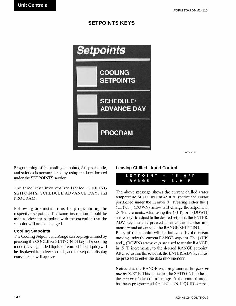
JOHnSOn COnTROLS142
FORm 150.72-nm1 (110)Unit Controls
Programming of the cooling setpoints, daily schedule, and safeties is accomplished by using the keys located under the SETPOINTS section.
The three keys involved are labeled COOLING SETPOINTS, SCHEDULE/ADVANCE DAY, and PROGRAM.
Following are instructions for programming the respective setpoints. The same instruction should be used to view the setpoints with the exception that the setpoint will not be changed.
Cooling SetpointsThe Cooling Setpoint and Range can be programmed by pressing the COOLING SETPOINTS key. The cooling mode (leaving chilled liquid or return chilled liquid) will be displayed for a few seconds, and the setpoint display entry screen will appear.
SETPOINTS KEYS
00069vIP
Leaving Chilled Liquid Control
The above message shows the current chilled water temperature SETPOINT at 45.0 °F (notice the cursor positioned under the number 0). Pressing either the ↑ (UP) or ↓ (DOWN) arrow will change the setpoint in .5 °F increments. After using the ↑ (UP) or ↓ (DOWN) arrow keys to adjust to the desired setpoint, the ENTER/ADV key must be pressed to enter this number into memory and advance to the RANGE SETPOINT.Entry of the setpoint will be indicated by the cursor moving under the current RANGE setpoint. The ↑ (UP) and ↓ (DOWN) arrow keys are used to set the RANGE, in .5 °F increments, to the desired RANGE setpoint. After adjusting the setpoint, the ENTER/ADV key must be pressed to enter the data into memory.
Notice that the RANGE was programmed for plus or minus X.X° F. This indicates the SETPOINT to be in the center of the control range. If the control mode has been programmed for RETURN LIQUID control,
S E T P O I N T = 4 5 . 0 ° F R A N G E = +/- 2 . 0 ° F

FORm 150.72-nm1 (110)
143JOHnSOn COnTROLS
7
(leaving chilled liquid control)
(return chilled liquid control)
The low limit, high limit, and default values for the keys under “SETPOINTS” are listed in Table 10.
Pressing the COOLING SETPOINTS a third time will bring up the display that allows the Maximum EMS-PWM Temperature Reset to be programmed. This message is shown below.
The Temp Reset value is the maximum allowable remote reset of the temperature setpoint. The setpoint can be reset upwards by the use of an Energy Management System. See page 152 and 164 for a detailed explanation of this feature.
As with the other setpoints, the ↑ (UP) arrow and ↓ (DOWN) arrow keys are used to change the Temp Reset value. After using the ↑ (UP) and ↓ (DOWN) arrows to adjust to the desired setpoint, the ENTER/ADV key must be pressed to enter this number into memory.
Schedule/Advance Day KeyThe SCHEDULE is a seven day daily schedule that allows one start/stop time per day. The schedule can be programmed Monday through Sunday with an alternate holiday schedule available. If no start/stop times are programmed, the unit will run on demand, providing the chiller is not shut off on a unit or system shutdown. The daily schedule is considered “not programmed” when the times in the schedule are all zeros (00:00 AM).
To set the schedule, press the SCHEDULE/ADVANCE DAY key. The display will immediately show the following display.
R E M S E T P = 4 4 . 0 ° F R A N G E = + / - 2 . 0 ° F
R E M S E T P = 4 4 . 0 ° F R A N G E = + 1 0 . 0 ° F
M A X E M S - P W M R E M O T E T E M P R E S E T = + 2 0 ° F
M O N S T A R T = 0 0 : 0 0 A M S T O P = 0 0 : 0 0 A M
the message below would be displayed in place of the previous message.When in leaving chilled liquid temperature control, the microprocessor will attempt to control the leaving water temperature within the temperature range of the setpoint plus or minus the range. In the above example, control will be in the range of 43 – 47 °F.
Return Chilled Liquid Control
In return chilled liquid control, the range no longer has a plus or minus X.X °F, but only a + X.X °F RANGE setpoint. This indicates that the setpoint is not centered within the RANGE but could be described as the bottom of the control range. A listing of the limits and the programmable values for the COOLING SETPOINTS are shown in Table 10.
The SETPOINT and RANGE displays just described were based on LOCAL control. If the unit was programmed for REMOTE control (under the OPTIONS key), the above programmed setpoints would have no effect.
When in return chilled liquid temperature control, the microprocessor will turn all compressors off at setpoint and will turn compressors on as return chilled liquid temperature rises. All compressors will be on at setpoint plus the range. If the range equals the temperature drop across the evaporator when fully loaded, the leaving chilled liquid temperature will remain near the setpoint plus or minus a few degrees as the chiller loads and unloads according to return chilled liquid temperature.
Both LEAVING and RETURN control are described in detail under the section on CAPACITY CONTROL.
Remote Setpoint ControlPressing the COOLING SETPOINTS key a second time will display the remote setpoint and cooling range. This display automatically updates about every 2 seconds. Notice that these setpoints are not “locally” programmable, but are controlled by a remote device such as an ISN control, remote reset option board, or remote PWM signal. These setpoints would only be valid if the unit was operating in the REMOTE mode.
The following messages illustrate both leaving chilled liquid control and return chilled liquid control respectively.
S E T P O I N T = 4 5 . 0 ° F R A N G E = + 1 0 . 0 ° F

JOHnSOn COnTROLS144
FORm 150.72-nm1 (110)Unit Controls
* Refer to Engineering Guide for operation below 30 °F (-1.1 °C). Alternate thermal expansion valves must be used below 30 °F (-1.1 °C).
* When using glycol, Leaving Chilled Liquid Setpoint should not be set below 20 °F (-6.7 °C).
** Do not exceed 55 °F (12.8 °C) setpoint before contacting the nearest Johnson Controls Office for application guidelines.
The line under the 0 is the cursor. If the value is wrong, it may be changed by using the ↑ (UP) and ↓ (DOWN) arrow keys until correct. Pressing the ENTER/ADV key will enter the times and then move the cursor to the minute box. The operation is then repeated if necessary. This process may be followed until the hour, minutes, and meridian (AM or PM) of both the START and STOP points are set. After changing the meridian of the stop time, pressing the ENTER/ADV key will advance the schedule to the next day.
Whenever the daily schedule is changed for Monday, all the other days will change to the new Monday schedule. This means if the Monday times are not applicable for the whole week then the exceptional days would need to be reprogrammed to the desired sched-ule.
To page to a specific day, press the SCHEDULE/ADVANCE DAY key until the desired day appears. The start and stop time of each day may be programmed differently using the ↑ (UP) and ↓ (DOWN) arrow, and ENTER/ADV keys.
After SUN (Sunday) schedule appears on the display a subsequent press of the SCHEDULE/ADVANCE DAY key will display the Holiday schedule. This is a two part display. The first reads:
The times may be set using the same procedure as described above for the days of the week. After changing the meridian of the stop time, pressing the ENTER/ADV key will advance the schedule to the following display:
The line below the empty space next to the S is the cursor and will move to the next empty space when the ENTER/ADV key is pressed. To set the Holiday, the cursor is moved to the space following the day of the week of the holiday and the ↑ (UP) arrow key is pressed. An * will appear in the space signifying that day as a holiday. The * can be removed by pressing the ↓ (DOWN) arrow key.
The Holiday schedule must be programmed weekly –once the Holiday schedule runs, it will revert to the normal daily schedule.
H O L S T A R T = 0 0 : 0 0 A M S T O P = 0 0 : 0 0 A M
S __ M T W T F S H O L I D A Y N O T E D B Y *
TABLE 10 – COOLING SETPOINTS, PROGRAMMABLE LIMITS AND DEFAULTSSETPOINT KEY MODE LOW LIMIT HIGH LIMIT DEFAULT
LEAvInG CHILLED LIqUID SETPOInTWATER COOLInG
40.0°F4.4°C
**70.0°F21.1°C
44.0°F6.7°C
GLYCOL COOLInG*
10.0°F-12.2°C
**70.0°F21.1°C
44.0°F6.7°C
LEAvInG CHILLED LIqUID COnTROL RAnGE — 1.5°F0.8°C
2.5°F1.4°C
2.0°F1.1°C
RETURnED CHILLED LIqUID SETPOInTWATER COOLInG
40.0°F4.4°C
70.0°F21.1°C
44.0°F6.7°C
GLYCOL COOLInG*
10.0°F-12.2°C
70.0°F21.1°C
44.0°F6.7°C
RETURn CHILLED LIqUID COnTROL RAnGE —
4.0°F2.2°C
20.0°F11.1°C
10.0°F5.6°C
mAX EmS-PWm REmOTE TEmPERATURE RESET —2°F
1.0°C40°F
22.0°C20°F
11.0°C

FORm 150.72-nm1 (110)
145JOHnSOn COnTROLS
7
Program Key
There are several operating parameters under the PROGRAM key that are programmable. These setpoints can be changed by pressing the PROGRAM key, and then the ENTER/ADV key to enter Program Mode. Continuing to press the ENTER/ADV key will display each operating parameter. While a particular parameter is being displayed, the ↑ (UP) and ↓ (DOWN) arrow keys can be used to change the value. After the value is changed, the ENTER/ADV key must be pressed to enter the data into memory. Table 11 shows the programmable limits and default values for each operating parameter.
Following are the displays for the programmable values in the order they appear:
DISCHARGE PRESSURE CUTOUT is the discharge pressure at which the system will shutdown as monitored by the optional discharge transducer. This is a software shutdown that acts as a backup for the mechanical high pressure switch located in the refrigerant circuit. The system can restart when the discharge pressure drops 40 PSIG (2.76 barg) below the cutout point.
If the optional discharge pressure transducer is not installed, this programmable safety would not apply. It should be noted that every system has a mechanical high pressure cutout that protects against excessive high discharge pressure regardless of whether or not the optional discharge pressure is installed.
The SUCTION PRESSURE CUTOUT protects the chiller from an evaporator freeze-up. If the suction pressure drops below the cutout point, the system will shut down. Typically, the cutout should be set to 80 PSIG (5.52 Bars) form water cooling.
There are some exceptions when the suction pressure is permitted to tem-porarily drop below the cutout point. Details are explained under the topic of SySTEM SAFETIES.
d D I S C H A R G E P R E S S U R E C U T O U T = 5 7 0 P S I G
S U C T I O N P R E S S U R E C U T O U T = 80 . 0 P S I G
The LOW AMBIENT TEMP CUTOUT allows the user to select the chiller outside ambient temperature cutout point. If the ambient falls below this point, the chiller will shut down. Restart can occur when temperature rises 2 °F (1.11 °C) above the cutout setpoint.
The LEAVING LIQUID TEMP CUTOUT protects the chiller from an evaporator freeze-up. Anytime the leaving chilled liquid temperature drops to the cutout point, the chiller shuts down. Restart will be permitted when the leaving chilled liquid temperature rises 2 °F (1.11 °C) above the cutout setpoint.
When water cooling mode is programmed (Options key), the value is fixed at 36.0 °F (2.22 °C) and cannot be changed. Glycol cooling mode can be programmed to values listed in Table 11.
The programmable anti-recycle timer assures that systems do not short cycle, and the compressor motors have sufficient time to dissipate heat after a start. This timer is programmable under the PROGRAM key between 300 – 600 seconds. Whenever possible, to reduce cycling and motor heating, the anti-recycle timer should be adjusted as high as possible. The programmable anti-recycle timer starts the timer when the first compressor in a system starts. The timer begins to count down. If all the compressors in the circuit cycle off, a compressor within the circuit will not be permitted to start until the anti-recycle timer has timed out. If the lead system has run for less than 5 minutes, 3 times in a row, the anti-recycle timer will be extended to 10 minutes, if currently programmed for less than 10 minutes.
The Fan Control On-Pressure is the programmed pressure value that is used to stage the condenser fans on, in relation to discharge pressure. Refer to Condenser Fan Control in the UNIT OPERATION section and Tables 17and 18.
L O W A M B I E N T T E M P C U T O U T = 2 5 . 0 ° F
L E A V I N G L I Q U I D T E M P C U T O U T = 3 6 . 0 ° F
A N T I R E C Y C L E T I M E R = 6 0 0 S E C
F A N C O N T R O L O N P R E S S U R E = X X X P S I G

JOHnSOn COnTROLS146
FORm 150.72-nm1 (110)Unit Controls
The Number of Fans Per System must be programmed as needed to match the number of fans on each system.
Depending on the option, the trip voltage for a specific system or unit high current trip can be programmed. It also calibrates the current readout under the OPER DATA key. The approximate programmed value is calculated using the following formulas:
System Trip Volts
For individual system high current trip programming on chillers:
• Add the sum of the compressor and fan RLA’s in the system
• Multiply the sum by 1.25 • Divide by 225A • The resulting voltage is the value that should be
programmed
For example, if fan and compressor RLA’s total 100A:
The programmed value will be 2.8V. A similar calculation and programming will be necessary for the other system in a 2-system chiller.
N U M B E R O F F A N S P E R S Y S T E M = X
S Y S X T R I P V O L T S = X . X V O L T S
U N I T T R I P V O L T S = X . X V O L T S
5V x 100A x 1.25 = 625VA = 2.8V 225A 225A
The Fan Differential Off Pressure is the programmed differential pressure value that is used to stage the condenser fans off, in relation to discharge pressure. Refer to Condenser Fan Control in the UNIT OPERATION section and Tables 17 and 18.
The TOTAL NUMBER OF COMPRESSORS is the total quantity of compressors in the chiller, and determines the stages of cooling available. Note in Table 11, the chiller may have single or dual systems. Dual system units may have 4, 5 or 6 compressors.
This MUST be programmed correctly to assure proper chiller operation.
F A N D I F F E R E N T I A L O F F P R E S S U R E = X X X P S I G
T O T A L N U M B E R O F C O M P R E S S O R S = 6

FORm 150.72-nm1 (110)
147JOHnSOn COnTROLS
7
Unit Trip Volts
For total chiller high current trip programming on 460VAC chillers:
• Add the sum of all the compressor and fan RLA’s in the chiller.
• Multiply the sum by 1.25 • Divide by 225A • The resulting voltage is the value that should be
programmed.
For example, if fan and compressor RLA’s total 180A:
The programmed value will be 5.0V.
5V x 180A x 1.25 = 1125VA = 5.0V 225A 225A
* The minimum discharge pressure allowed is 235 PSIG. The Fan Differential Off Pressure High Limit will be lowered (reduced) to prevent going below 235 PSIG based on where the fan control On Pressure is programmed.
When communications is required with a BAS or OptiView Panel, individual unit IDs are necessary for communications with specific chillers on a single RS-485 line. ID 0-7 is selectable.
R E M O T E U N I T I D P R O G R A M M E D = X
TABLE 11 – PROGRAM KEY LIMITS AND DEFAULTPROGRAM VALUE MODE LOW LIMIT HIGH LIMIT DEFAULT
DISCHARGE PRESSURE CUTOUT — 325 PSIG 575 PSIG 570 PSIG
22.4 BARG 39.6 BARG 39.3 BARG
SUCTION PRESSURE CUTOUTWATER COOLInG
80.0 PSIG 120.0 PSIG 80.0 PSIG5.52 BARG 8.27 BARG 5.52 BARG
GLYCOL COOLInG42.0 PSIG 70.0 PSIG 44.0 PSIG2.9 BARG 4.83 BARG 3.03 BARG
LOW AMBIENT TEMP, CUTOUT
STAnDARD AmBIEnT
25.0°F 60.0°F 25.0°F-3.9°C 15.6°C -3.9°C
LOW AmBIEnT0°F 60.0°F 25.0°F
-17.8°C 15.6°C -3.9°C
LEAVING CHILLED LIQUID TEMP CUTOUT
WATER COOLInG — — 36.0°F2.2°C
GLYCOL COOLInG1.0°F 36.0°F 36.0°F
-18.3°C 2.2°C 2.2°CANTI-RECYCLE TIMER — 300 SEC. 600 SEC. 600 SEC.
FAN CONTROL ON PRESSURE — 360 PSIG 485 PSIG 385 PSIG
24.8 BARG 33.4 BARG 26.5 BARG
FAN DIFFERENTIAL OFF PRESSURE — 80 PSIG 160 PSID* 125 PSID
5.51 BARG 11.03 BARG* 8.62 BARG
TOTAL NUMBER OF COMPRESSORSInGLE SYSTEm 2 3 3DUAL SYSTEm 4 6 6
NUMBER OF FANS PER SYSTEM 2 4 3
UNIT/SYSTEM TRIP VOLTSCURREnT FEEDBACK
0.5 4.5 2.5
REMOTE UNIT ID — 0 7 0

JOHnSOn COnTROLS148
FORm 150.72-nm1 (110)Unit Controls
TABLE 12 – SETPOINTS QUICK REFERENCE LIST
LD07404c
Table 16 provides a quick reference of the setpoints list for the Setpoints Keys.
Cooling Setpoints Key Schedule/ Program Mode (press key to adv.) Advance Day Key (press enter to adv.) Local Leaving Mon. – Sun. Discharge Water Temp Control & Pressure (Display Only) Holiday Cutout Schedule
Chilled Liquid Suction Setpoint Pressure & Cutout Range
Remote Setpoint Low Ambient Temp. & Cutout Range (Display Only)
Leaving Liquid EMS - PWM Temperature Remote Temp Cutout Reset Setpoint Anti-Recycle Timer
Fan Control On-Pressure
Fan Differential Off-Pressure
Quick Reference Programming ChartSetpoints Section
SYS / Unit
Trip Volts Option
Number ofFans Per System
Total Numbers
of
Compressors
Remote Unit ID
Table 12

FORm 150.72-nm1 (110)
149JOHnSOn COnTROLS
7
This allows both systems to runor
This turns system 2 off
This turns system 1 offor
This turns systems 1 and 2 off
Turning a system off with its system switch allows a pumpdown to be per-formed prior to shutdown.
Option 3 – Chilled Liquid Cooling Type
The chilled liquid is water. The Cooling Setpoint can be programmed from 40 °F to 70 °F (4.4 °C to 21.1 °C)
or
The chilled liquid is glycol. The Cooling Setpoint can be programmed from 10 °F to 70 °F (-12.2 °C to 21.1 °C).
S Y S 1 S W I T C H O N S Y S 2 S W I T C H O F F
S Y S 1 S W I T C H O F F S Y S 2 S W I T C H O N
S Y S 1 S W I T C H O F F S Y S 2 S W I T C H O F F
C H I L L E D L I Q U I D W A T E R
C H I L L E D L I Q U I D G L Y C O L
UNIT KEYS
Options KeyThere are many user programmable options under the OPTIONS key. The OPTIONS key is used to scroll through the list of options by repeatedly pressing the OPTIONS key. After the selected option has been displayed, the ↑ (UP) and ↓ (DOWN) arrow keys are then used to change that particular option. After the option is changed, the ENTER/ADV key must be pressed to enter the data into memory.
Many of the OPTIONS displayed are only programmable under the SERVICE MODE and not under the OPTIONS key. Options only program-mable under the SERVICE MODE are noted in the details describing the option.
Table 13 shows the programmable options. Following are the displays in the order they appear:
Option 1 – Language
English, Spanish, French, German, and Italian can be programmed.
Option 2 – System Switches (two system units only, single system display is similar)
D I S P L A Y L A N G U A G E E N G L I S H
S Y S 1 S W I T C H O N S Y S 2 S W I T C H O N
00070vIP
OPTIONS
CLOCK

JOHnSOn COnTROLS150
FORm 150.72-nm1 (110)Unit Controls
Option 4 – Ambient Control Type
The low ambient cutout is adjustable from 25 °F to 60 °F (-3.9 °C to 15.6 °C).
or
The low ambient cutout is programmable down to 0 °F (-17.8 °C). A low ambient kit MUST be installed for this option to be chosen. If the kit is NOT installed, and low ambient is selected, low pressure faults and compressor damage may occur.
Option 5 – Local/Remote Control Type
When programmed for LOCAL, an ISN or RCC control can be used to monitor only. The micro panel will operate on locally programmed values and ignore all commands from remote devices, or through the RS-485 inputs. The chiller will communicate and send data to the remote monitoring devices.
or
This mode should be selected when an ISN or RCC control is to be used to control the chiller. This mode will allow the ISN to control the following items: Remote Start/Stop, Cooling Setpoint, Load Limit, and History Buffer Request. If the unit receives no valid ISN transmission for 5 minutes, it will revert back to the locally programmed values.
Option 6 – Unit Control Mode
Unit control is based on return chilled liquid temp. Return Chilled Liquid Control can only be selected on units that have 4 to 6 compressors (dual system units).
or
A M B I E N T C O N T R O L S T A N D A R D
A M B I E N T C O N T R O L L O W A M B I E N T
L O C A L / R E M O T E M O D E L L O C A L
L O C A L / R E M O T E M O D E R E M O T E
C O N T R O L M O D E R E T U R N L I Q U I D
C O N T R O L M O D E L E A V I N G L I Q U I D
Option 7 – Display Units
This mode displays system operating values in Imperial units of °F or PSIG.
or
This mode displays system operating values in Scientific International Units of °C or barg.
Option 8 – Lead/Lag Type (two system units only)
SYS 1 selected as lead compressor. SYS 1 lead option MUST be chosen if Hot Gas Bypass is installed.
or
SYS 2 selected as lead compressor.or
Lead/lag between systems may be selected to help equalize average run hours between systems on chillers with 2 refrigerant systems. Auto lead/lag allows automatic lead/lag of the two systems based on an average run hours of the compressors in each system. A new lead/lag assignment is made whenever all compressors shut down. The microprocessor will then assign the “lead” to the system with the shortest average run time.
Option 9 – Condenser Fan Control Mode
Condenser fans are controlled by discharge pressure only. This mode must be chosen.
or
D I S P L A Y U N I T S I M P E R I A L
D I S P L A Y U N I T S S I
L E A D / L A G C O N T R O L M A N U A L S Y S 1 L E A D
L E A D / L A G C O N T R O L M A N U A L S Y S 2 L E A D
L E A D / L A G C O N T R O L A U T O M A T I C
F A N C O N T R O L D I S C H A R G E P R E S S U R E
FORM 150.72-NM1 (110)
151JOHNSON CONTROLS
7
Option 12 – Power Fail Restart
Chiller auto restarts after a power failure.
After a power failure, the UNIT switch must be toggled before restart at the unit is allowed. NORMALLY MANUAL RESTART should NOT BE SELECTED.
Option 13 – Soft Start Enable/Disable
SOFT START “DISABLED” MUST be selected on all chillers.
This message may not be viewable on non-European chillers.
Option 14 – Unit Type
The UNIT TYPE message cannot be modified under the UNIT keys.
“liquid CHillER” must be dis-played, or damage to compressors or other components will occur if oper-ated in the HEAT PuMP or CON-dENSiNG uNiT modes.
If unit type needs to be changed to make the unit a liquid chiller, remove power and then remove the jumper between J11-7 and J11-12 on the I/O Board. Reapply power to the micropanel and the microprocessor will store the change.
Option 15 – Refrigerant Type
Refrigerant type R-410A must be selected under Service Mode. Refrigerant type is displayed under the OPTIONS Key, but is only programmable in Service Mode.
P O W E R F A I L R E S T A R T A U T O M A T I C
P O W E R F A I L R E S T A R T M A n U A L
S O F T S T A R T D I S A b L E D
U n I T T y P E L I q U I D C h I L L E R
R E F R I g E R A n T T y P E R – 4 1 0 A
Do not select this option on R-410A chillers.
Option 10 – Manual Override Mode
This option allows overriding of the daily schedule that is programmed. MANUAL OVERRIDE MODE – DISABLED indicates that override mode has no effect.
or
Manual Override Mode is enabled. This is a service function and when enabled, will allow the unit to start when shut down on the daily schedule. It will automatically be disabled after 30 minutes.
Option 11 – Current Feedback Options Installed
This mode should be selected when the panel is not equipped with current sensing capability.
or
This mode should be selected when an optional 2ACE Module is installed to allow combined current monitoring of all systems by sensing current on the incoming line.
or
This mode should be selected when an optional 2ACE module is installed to allow individual current monitoring of each system. SYS 1 input is to J7 of the I/O. SYS 2 input is to J8 of the I/O.
F A n C O n T R O L A M b I E n T & D S C h P R E S S
M A n U A L O V E R R I D E M O D E E n A b L E D
C U R R E n T F E E D b A C k n O n E
C U R R E n T F E E D b A C k O n E P E R U n I T
C U R R E n T F E E D b A C k O n E P E R S y S T E M
M A n U A L O V E R R I D E M O D E D I S A b L E D

JOHnSOn COnTROLS152
FORm 150.72-nm1 (110)Unit Controls
Incorrect programming may cause damage to compressors.
Option 16 – Expansion Valve Type
Expansion valve type, thermostatic or electronic may be selected under Service Mode. Expansion valve type is displayed under the OPTIONS key, but is only programmable in Service Mode. YLAA chillers will typically always be equipped with thermostatic expansion valves.
Incorrect programming may cause damage to compressors.
Also see the “Unit Keys Programming Quick Reference List” in Table 13.
Option 17 – Flash Card Update
A Flash Card is used to input the operating program into the chiller IPU. A Flash Card is used instead of an EPROM. Normally, a Flash Card update is not required and the message above will be displayed.
If the operating software is to be updated, insert the Flash Card into the Flash Card input port. Turn off the unit switch and set the FLASH CARD UPDATE TO “ENABLED” using the ↑ and ↓ keys.
Press the ENTER key and the following message will be displayed until the update has been completed. The keypad and display will not respond during the update. DO NOT reset or power down the chiller until the update is completed.
E X P A N S I O N V A L V E T Y P E T H E R M O S T A T I C
F L A S H C A R D U P D A T E D I S A B L E D
F L A S H C A R D U P D A T E E N A B L E D
After the update is completed, an automatic reboot will occur. If an error occurred, the following message will appear with the error code and no reboot will occur:
If the update resulted in an error, the original program will still be active. When an error occurs, assure the correct Flash Card was utilized. Incorrect chiller software will cause an error. If this is not the case, the Flash Card is most likely defective or the IPU and I/O combo board is bad.
Option 18 – Remote Temperature Reset
Remote Temp Reset input selection is programmable according to the type of input utilized. The following options are available:
• DISABLED (default) • 0.0 – 10.0 (DC) • 2.0 – 10.0V (DC) • 0.0 – 20.0 mA • 4.0 – 20.0 mA
The options display message for Re-mote Temp Reset Input only appears if the Temp Reset Option is enabled un-der Service Mode. The option must be enabled under the Service Mode for the Remote Temperature Reset to oper-ate.
F L A S H C A R D U P D A T I N G P L E A S E W A I T . . .
F L A S H C A R D U P D A T E E R R O R XXXXX
R E M O T E T E M P R E S E T I N P U T XXXXXXXXXXXXXX
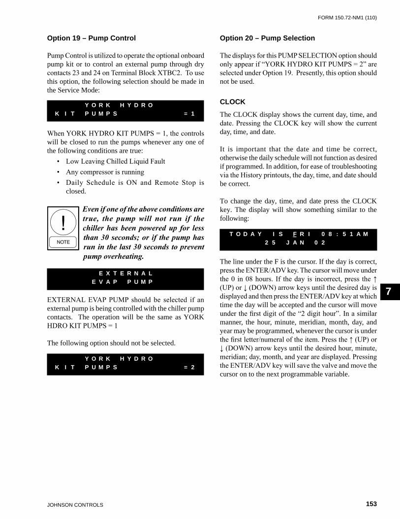
FORm 150.72-nm1 (110)
153JOHnSOn COnTROLS
7
Option 19 – Pump Control
Pump Control is utilized to operate the optional onboard pump kit or to control an external pump through dry contacts 23 and 24 on Terminal Block XTBC2. To use this option, the following selection should be made in the Service Mode:
When YORK HYDRO KIT PUMPS = 1, the controls will be closed to run the pumps whenever any one of the following conditions are true:
• Low Leaving Chilled Liquid Fault • Any compressor is running • Daily Schedule is ON and Remote Stop is
closed.
Even if one of the above conditions are true, the pump will not run if the chiller has been powered up for less than 30 seconds; or if the pump has run in the last 30 seconds to prevent pump overheating.
EXTERNAL EVAP PUMP should be selected if an external pump is being controlled with the chiller pump contacts. The operation will be the same as YORK HDRO KIT PUMPS = 1
The following option should not be selected.
Y O R K H Y D R O K I T P U M P S = 1
E X T E R N A L E V A P P U M P
Y O R K H Y D R O K I T P U M P S = 2
Option 20 – Pump Selection
The displays for this PUMP SELECTION option should only appear if “YORK HYDRO KIT PUMPS = 2” are selected under Option 19. Presently, this option should not be used.
CLOCK
The CLOCK display shows the current day, time, and date. Pressing the CLOCK key will show the current day, time, and date.
It is important that the date and time be correct, otherwise the daily schedule will not function as desired if programmed. In addition, for ease of troubleshooting via the History printouts, the day, time, and date should be correct.
To change the day, time, and date press the CLOCK key. The display will show something similar to the following:
The line under the F is the cursor. If the day is correct, press the ENTER/ADV key. The cursor will move under the 0 in 08 hours. If the day is incorrect, press the ↑ (UP) or ↓ (DOWN) arrow keys until the desired day is displayed and then press the ENTER/ADV key at which time the day will be accepted and the cursor will move under the first digit of the “2 digit hour”. In a similar manner, the hour, minute, meridian, month, day, and year may be programmed, whenever the cursor is under the first letter/numeral of the item. Press the ↑ (UP) or ↓ (DOWN) arrow keys until the desired hour, minute, meridian; day, month, and year are displayed. Pressing the ENTER/ADV key will save the valve and move the cursor on to the next programmable variable.
T O D A Y I S F R I 0 8 : 5 1 A M 2 5 J A N 0 2

JOHnSOn COnTROLS154
FORm 150.72-nm1 (110)Unit Controls
TABLE 13 – UNIT KEYS OPTIONS PROGRAMMING QUICK REFERENCE LIST
Table 13 provides a quick reference list for the Unit key setpoints. LD07405d
Options Key(press Options Key
to adv.)
Display Language
System Switcheson/off
Chilled Liquid Type(water or glycol)
Ambient Control(standard or low)
Local/Remote Mode
Unit Control Mode(Return or Leaving)
Display Units(English or Metric)
System Lead/Lag Control(Manual or Automatic)
Fan Control Mode
Manual Override Mode
Current Feedback Option
Soft Start Option
Unit Type(”Chiller” MUST be Selected
Via No Jumper Installed(Viewable Only)
Refrigerant TypeR-410A
(Programmed under Service Mode)Viewable Only)
Power Failure Restart
Expansion Valve Type
(Thermoplastic or Electric)
(Programmed under Service Mode, Viewable Only) Must be programmed
for Thermostatic
Flash Card Update
Remote Temp Reset
Pump Control
Pump Selection

FORm 150.72-nm1 (110)
155JOHnSOn COnTROLS
8
CAPACITY CONTROL
To initiate the start sequence of the chiller, all run permissive inputs must be satisfied (flow/remote start/stop switch), and no chiller or system faults exist.
The first phase of the start sequence is initiated by the Daily Schedule Start or any Remote Cycling Device. If the unit is shut down on the daily schedule, the chilled water pump contacts (Terminals 23 and 24 of XTBC2) will close to start the pump when the daily schedule start time has been reached. Once flow has been established and the flow switch closes, capacity control functions are initiated, if the remote cycling contacts wired in series with the flow switch are closed.
It should be noted that the chilled water pump contacts (Terminals 23 and 24 of XTBC2) are not required to be used to cycle the chilled water pump. However, in all cases the flow switch must be closed to allow unit operation.
The control system will evaluate the need for cooling by comparing the actual leaving or return chilled liquid temperature to the desired setpoint, and regulate the leaving or return chilled liquid temperature to meet that desired setpoint.
SUCTION PRESSURE LIMIT CONTROLS
The anticipatory controls are intended to prevent the unit from ever actually reaching a low-pressure cutout. Loading is prevented, if the suction pressure drops below 1.15 x suction pressure cutout (15% below the cutout). Loading may reoccur after suction pressure rises above the unload point and a period of one minute elapses. This control is only operable if the optional suction pressure transducers are installed.
DISCHARGE PRESSURE LIMIT CONTROLS
The discharge pressure limit controls unload a system before it reaches a safety limit due to high load or dirty condenser coils. The microprocessor monitors discharge pressure and unloads a system, if fully loaded, by one compressor when discharge pressure exceeds the programmed cutout minus 10 PSIG (0.69 barg). Reloading will occur when the discharge pressure on the affected system drops to 85% of the unload pressure and 10 minutes have elapsed.
This control is only applicable if optional discharge pressure transducers are installed.
LEAVING CHILLED LIQUID CONTROL
The setpoint, when programmed for Leaving Chilled Liquid Control, is the temperature the unit will control to within plus or minus the (control) cooling range. The Setpoint High Limit is the Setpoint plus the Cooling Range. The Setpoint Low Limit is the Setpoint minus the Cooling Range. Fig. 26 should be utilized to aid in understanding the following description of Leaving Chilled Liquid Control.
SECTION 8 – UNIT OPERATION
If the leaving chilled liquid temperature is above the Setpoint High Limit, the lead compressor on the lead system will be energized along with the liquid line solenoid. Upon energizing any compressor, the 60 second Anti-Coincidence timer will be initiated to prevent multiple compressors from turning on.
If after 60 seconds of run-time the leaving chilled liquid temperature is still above the Setpoint High Limit, the next compressor in sequence will be energized. Additional compressors will be energized at a rate of once every 60 seconds if the chilled liquid temperature remains above the Setpoint High Limit and the chilled liquid temperature is dropping less than 3 °F/min. The lag system will not be allowed to start a compressor until the lead system has run for 5 minutes.
If the chilled liquid temperature falls below the Setpoint High Limit but is greater than the Setpoint Low Limit, loading and unloading do not occur. This area of control is called the control range.
If the chilled liquid temperature drops to between Setpoint Low Limit and 0.5 °F (.28 °C) below the Setpoint Low Limit, unloading (a compressor turns off) occurs at a rate of 1 every 30 seconds. If the chilled liquid temperature falls to a value greater than 0.5 °F (.28 °C) below the Setpoint Low Limit but not greater than 1.5 °F (.83 °C) below the Setpoint Low Limit, unloading occurs
FIG. 26 – LEAVING WATER TEMPERATURE CONTROL EXAMPLE
44.0 ºF(6.7 ºC)
Low Limit
46.0 ºF(7.8 ºC)Setpoint
48.0 ºF(8.9 ºC)
High Limit
Leaving Water Temp. Control - Compressor StagingSetpoint = 46.0 ºF (7.8 ºC) Range = +/-2 ºF (1.1 ºC)
30 sec.unloading
60 sec.loading
Contol Range(no compressor staging)
LWT
LD14404
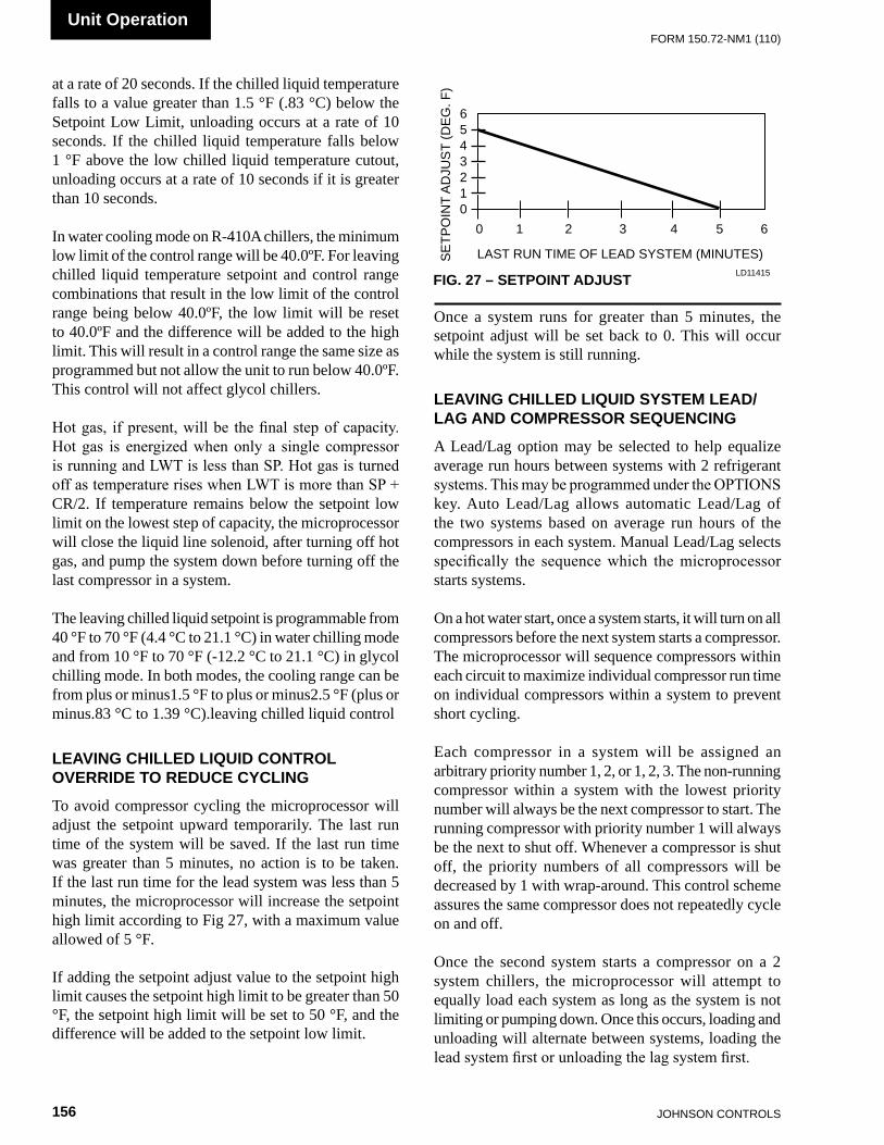
JOHnSOn COnTROLS156
FORm 150.72-nm1 (110)Unit Operation
0 1 2 3 4 5 6
LAST RUn TImE OF LEAD SYSTEm (mInUTES)SE
TPO
InT
AD
JUS
T (D
EG
. F)
6543210
FIG. 27 – SETPOINT ADJUST LD11415
at a rate of 20 seconds. If the chilled liquid temperature falls to a value greater than 1.5 °F (.83 °C) below the Setpoint Low Limit, unloading occurs at a rate of 10 seconds. If the chilled liquid temperature falls below 1 °F above the low chilled liquid temperature cutout, unloading occurs at a rate of 10 seconds if it is greater than 10 seconds.
In water cooling mode on R-410A chillers, the minimum low limit of the control range will be 40.0ºF. For leaving chilled liquid temperature setpoint and control range combinations that result in the low limit of the control range being below 40.0ºF, the low limit will be reset to 40.0ºF and the difference will be added to the high limit. This will result in a control range the same size as programmed but not allow the unit to run below 40.0ºF. This control will not affect glycol chillers.
Hot gas, if present, will be the final step of capacity. Hot gas is energized when only a single compressor is running and LWT is less than SP. Hot gas is turned off as temperature rises when LWT is more than SP + CR/2. If temperature remains below the setpoint low limit on the lowest step of capacity, the microprocessor will close the liquid line solenoid, after turning off hot gas, and pump the system down before turning off the last compressor in a system.
The leaving chilled liquid setpoint is programmable from 40 °F to 70 °F (4.4 °C to 21.1 °C) in water chilling mode and from 10 °F to 70 °F (-12.2 °C to 21.1 °C) in glycol chilling mode. In both modes, the cooling range can be from plus or minus1.5 °F to plus or minus2.5 °F (plus or minus.83 °C to 1.39 °C).leaving chilled liquid control
LEAVING CHILLED LIQUID CONTROL OVERRIDE TO REDUCE CYCLING
To avoid compressor cycling the microprocessor will adjust the setpoint upward temporarily. The last run time of the system will be saved. If the last run time was greater than 5 minutes, no action is to be taken. If the last run time for the lead system was less than 5 minutes, the microprocessor will increase the setpoint high limit according to Fig 27, with a maximum value allowed of 5 °F.
If adding the setpoint adjust value to the setpoint high limit causes the setpoint high limit to be greater than 50 °F, the setpoint high limit will be set to 50 °F, and the difference will be added to the setpoint low limit.
Once a system runs for greater than 5 minutes, the setpoint adjust will be set back to 0. This will occur while the system is still running.
LEAVING CHILLED LIQUID SYSTEM LEAD/LAG AND COMPRESSOR SEQUENCING
A Lead/Lag option may be selected to help equalize average run hours between systems with 2 refrigerant systems. This may be programmed under the OPTIONS key. Auto Lead/Lag allows automatic Lead/Lag of the two systems based on average run hours of the compressors in each system. Manual Lead/Lag selects specifically the sequence which the microprocessor starts systems.
On a hot water start, once a system starts, it will turn on all compressors before the next system starts a compressor. The microprocessor will sequence compressors within each circuit to maximize individual compressor run time on individual compressors within a system to prevent short cycling.
Each compressor in a system will be assigned an arbitrary priority number 1, 2, or 1, 2, 3. The non-running compressor within a system with the lowest priority number will always be the next compressor to start. The running compressor with priority number 1 will always be the next to shut off. Whenever a compressor is shut off, the priority numbers of all compressors will be decreased by 1 with wrap-around. This control scheme assures the same compressor does not repeatedly cycle on and off.
Once the second system starts a compressor on a 2 system chillers, the microprocessor will attempt to equally load each system as long as the system is not limiting or pumping down. Once this occurs, loading and unloading will alternate between systems, loading the lead system first or unloading the lag system first.
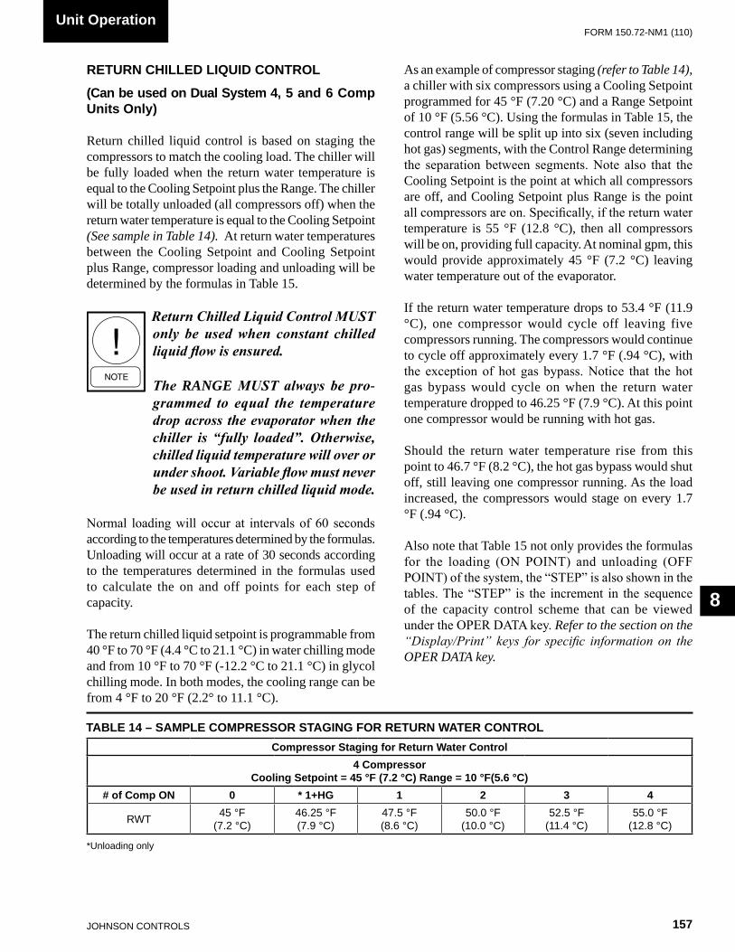
FORm 150.72-nm1 (110)
157JOHnSOn COnTROLS
8
RETURN CHILLED LIQUID CONTROL
(Can be used on Dual System 4, 5 and 6 Comp Units Only)
Return chilled liquid control is based on staging the compressors to match the cooling load. The chiller will be fully loaded when the return water temperature is equal to the Cooling Setpoint plus the Range. The chiller will be totally unloaded (all compressors off) when the return water temperature is equal to the Cooling Setpoint (See sample in Table 14). At return water temperatures between the Cooling Setpoint and Cooling Setpoint plus Range, compressor loading and unloading will be determined by the formulas in Table 15.
Return Chilled Liquid Control MUST only be used when constant chilled liquid flow is ensured.
The RAnGe MUST always be pro-grammed to equal the temperature drop across the evaporator when the chiller is “fully loaded”. Otherwise, chilled liquid temperature will over or under shoot. Variable flow must never be used in return chilled liquid mode.
Normal loading will occur at intervals of 60 seconds according to the temperatures determined by the formulas. Unloading will occur at a rate of 30 seconds according to the temperatures determined in the formulas used to calculate the on and off points for each step of capacity.
The return chilled liquid setpoint is programmable from 40 °F to 70 °F (4.4 °C to 21.1 °C) in water chilling mode and from 10 °F to 70 °F (-12.2 °C to 21.1 °C) in glycol chilling mode. In both modes, the cooling range can be from 4 °F to 20 °F (2.2° to 11.1 °C).
As an example of compressor staging (refer to Table 14), a chiller with six compressors using a Cooling Setpoint programmed for 45 °F (7.20 °C) and a Range Setpoint of 10 °F (5.56 °C). Using the formulas in Table 15, the control range will be split up into six (seven including hot gas) segments, with the Control Range determining the separation between segments. Note also that the Cooling Setpoint is the point at which all compressors are off, and Cooling Setpoint plus Range is the point all compressors are on. Specifically, if the return water temperature is 55 °F (12.8 °C), then all compressors will be on, providing full capacity. At nominal gpm, this would provide approximately 45 °F (7.2 °C) leaving water temperature out of the evaporator.
If the return water temperature drops to 53.4 °F (11.9 °C), one compressor would cycle off leaving five compressors running. The compressors would continue to cycle off approximately every 1.7 °F (.94 °C), with the exception of hot gas bypass. Notice that the hot gas bypass would cycle on when the return water temperature dropped to 46.25 °F (7.9 °C). At this point one compressor would be running with hot gas.
Should the return water temperature rise from this point to 46.7 °F (8.2 °C), the hot gas bypass would shut off, still leaving one compressor running. As the load increased, the compressors would stage on every 1.7 °F (.94 °C).
Also note that Table 15 not only provides the formulas for the loading (ON POINT) and unloading (OFF POINT) of the system, the “STEP” is also shown in the tables. The “STEP” is the increment in the sequence of the capacity control scheme that can be viewed under the OPER DATA key. Refer to the section on the “Display/Print” keys for specific information on the OPER DATA key.
Unit Operation
TABLE 14 – SAMPLE COMPRESSOR STAGING FOR RETURN WATER CONTROL
*Unloading only
Compressor Staging for Return Water Control4 Compressor
Cooling Setpoint = 45 °F (7.2 °C) Range = 10 °F(5.6 °C)# of Comp ON 0 * 1+HG 1 2 3 4
RWT 45 °F(7.2 °C)
46.25 °F(7.9 °C)
47.5 °F(8.6 °C)
50.0 °F(10.0 °C)
52.5 °F(11.4 °C)
55.0 °F(12.8 °C)

JOHnSOn COnTROLS158
FORm 150.72-nm1 (110)Unit Operation
RETURN CHILLLED LIQUID SYSTEM LEAD/LAG AND COMPRESSOR SEQUENCING
A lead/Lag option may be selected to help equalize average run hours between systems with 2 refrigerant systems. This may be programmed under the OPTIONS key. Auto Lead/Lag of the 2 systems based on average run hours of the compressors in each system. Manual Lead/Lag selects specifically the sequence which the microprocessor starts the systems.
The microprocessor will sequence compressors load and unload systems according to Table 16. The microprocessor will lead/lag compressors within each circuit to maximize individual compressor run time for the purpose of lubrication. It will also prevent the
same compressor from starting 2 times in a row. The microprocessor will not attempt to equalize run time on individual compressors within a system.
Each compressor in a system will be assigned an arbitrary number 1, or 2. The non-running compressor within a system with the lowest priority number will always be the next compressor to start. The running compressor with priority number 1 will always be the next compressor to shut off. Whenever a compressor is shut off, the priority numbers of all compressors in each system will be decreased by 1 with the wrap around. This control scheme assures the same compressor does not repeatedly cycle on and off.
notes:1. Step 1 is Hot Gas Bypass and is skipped when loading occurs. Hot Gas Bypass operation is inhibited during Pumpdown.2. Step 3 is skipped when loading occurs.3. Step 4 is skipped when unloading occurs.
TABLE 15 – RETURN CHILLED LIQUID CONTROL FOR 4 COMPRESSORS (6 STEPS)
* STEP can be viewed using the OPER DATA key and scrolling to COOLInG DEmAnD.
*STEP COMPRESSOR COMPRESSOR ON POINT COMPRESSOR OFF POINT 0 0 SETPOInT SETPOInT 1 1 W/HGB SP + CR/8 (note 1) SETPOInT 2 1 nO HGB SP + CR/4 SP + CR/8 3 2 SP + 2*CR/4 (note 2) SP + CR/4 4 2 SP + 2*CR/4 SP + CR/4 (note 3) 5 3 SP + 3*CR/4 SP + 2*CR/4 6 4 SP + CR SP + 3*CR/4
LEAD SYSTEM LAG SYSTEM Step COMP 1 COMP 2 -
See NOTE 1
See NOTE 2
See NOTE 3
COMP 1 COMP 2 -0 OFF OFF - OFF OFF -1 On + HG OFF - OFF OFF -2 On OFF - OFF OFF -3 On OFF - On OFF -4 On On - OFF OFF -5 On On - On OFF -6 On On - On On -
nOTES1. Step is Hot Gas Bypass and is skipped when loading occurs. Hot Gas Bypass operation is inhibited during pumpdown. For Leaving Chilled
Liquid Control the Hot Gas Bypass solenoid is energized only when the lead compressor is running and the LWT < SP, the Hot Gas Bypass solenoid is turned off when the LWT > SP + CR/2.
1. Step 1 is not used for loading or unloading.2. Step 3 is skipped when loading occurs.3. Step 4 is skipped when unloading occurs.
TABLE 16 – RETURN CHILLED LIQUID CONTROL FOR 4 COMPRESSORS (6 STEPS)
FORm 150.72-nm1 (110)
159JOHnSOn COnTROLS
8
ANTI-RECYCLE TIMER
The programmable anti-recycle timer assures that systems do not cycle. This timer is programmable under the PROGRAM key between 300 – 600 seconds. Whenever possible, to reduce cycling and motor heating, the anti-recycle timer should be adjusted to 600 seconds. The programmable anti-recycle timer starts the timer when the first compressor in a system starts. The timer begins to count down. If all of the compressors in a circuit cycle off, a compressor within the circuit will not be permitted to start until the anti-recycle timer has timed out. If the lead system has run for less than 5 minutes, 3 times in a row, the anti-recycle timer will be extended to 10 minutes.
ANTI-COINCIDENCE TIMER
This timer is not present on single-system units. Two timing controls are present in software to assure compressors within a circuit or between systems, do not start simultaneously. The anti-coincidence timer assures there is at least a one minute delay between system starts on 2-circuit systems. This timer is NOT programmable. The load timers further assure that there is a minimum time between compressor starts within a system.
EVAPORATOR PUMP CONTROL AND YORK HYDRO KIT PUMP CONTROL
The evaporator pump dry contacts (XTBC2 – terminals 23 – 24) are energized when any of the following conditions are true:
1. Low Leaving Chilled Liquid Fault 2. Any compressor is running 3. Daily Schedule is ON, Unit Switch is ON and
Remote Stop is closed.
The pump will not run if the micro panel has been powered up for less than 30 seconds or if the pump has run in the last 30 seconds to prevent pump motor overheating.
Whenever the option “YORK HYDRO KIT PUMPS = 1” is selected under the OPTIONS key, the pump control will be as described above. DO NOT SELECT the option “YORK HYDRO KIT PUMPS = 2” under the OPTIONS key. If a dual pump option is installed, the active pump is selected by the selector switch.
EVAPORATOR HEATER CONTROL
The evaporator heater is controlled by ambient air temperature. When the ambient temperature drops below 40 °F (4.4 °C) the heater is turned on. When the temperature rises above 45 °F (7.2 °C) the heater is turned off. An under voltage condition will keep the heater off until full voltage is restored to the system.
PUMPDOWN CONTROL
Each system has a pump-down feature upon shut-off. Manual pumpdown from the keypad is not possible. On a non-safety, non-unit switch shutdown, all compressors but one in the system will be shut off. The LLSV will also be turned off. The final compressor will be allowed to run until the suction pressure falls below the cutout, or for 180 seconds, whichever comes first.
STANDARD CONDENSER FAN CONTROL
Condenser fan operation must be programmed with the OPTIONS key under “Fan Control.” Condenser fan must be selected for Discharge Pressure only. Fan control by discharge pressure will work according to the tables on the following pages. The fan control on-pressure and fan differential off-pressure are programmable under the PROGRAM key. Standard fan control operates down to a temperature of 25° F.
The delay between turning on and off fan stages is always fixed at 5 seconds.
When a fan stage is turned on by pressure, the on pressure for the next stage is increased 20 PSIG and ramped back to the programmed on pressure over the next 20 seconds. Typically, standard ambient control ON pressure should be programmed at 385 PSIG with a differential of 125 PSIG.
When a fan stage is turned off (programmed on pressure minus programmed differential), the off pressure for the next stage is decreased 20 PSIG and ramped back to the programmed off pressure minus the differential over the next 20 seconds.
Condenser fan locations are shown in Fig. 28. Detailed Standard Fan Control operation is shown in Table 17 and 18.
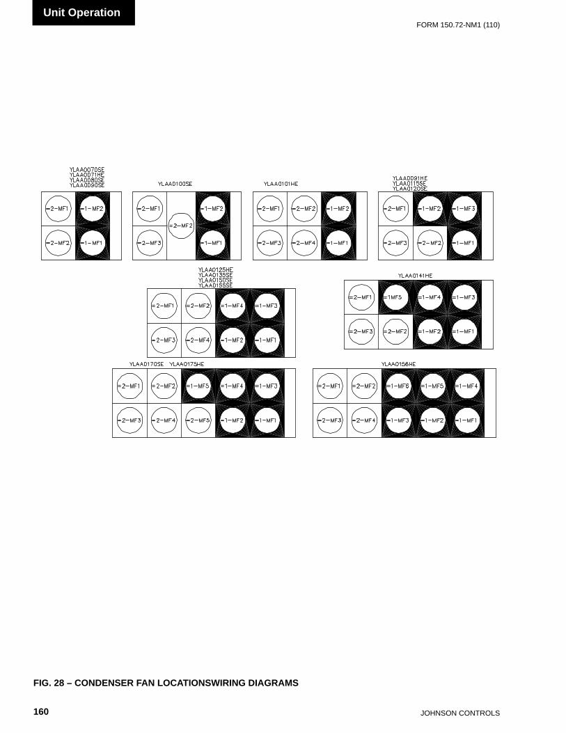
JOHnSOn COnTROLS160
FORm 150.72-nm1 (110)Unit Operation
FIG. 28 – CONDENSER FAN LOCATIONSWIRING DIAGRAMS
035-21589-107 REV A

FORm 150.72-nm1 (110)
161JOHnSOn COnTROLS
8
TABLE 17 – YLAA STANDARD CONDENSER FAN CONTROL USING DISCHARGE PRESSURE ONLY (2, 3, OR 4 FANS PER SYSTEM)
FAN STAGE
ON* OFF**IPUII I/O OUTPUT
FAN CONTACTOR
FAN #
SYS 1 SYS 2 SYS 1 SYS 2 SYS 1 SYS 2
1DP > PROGRAmmED FAn COnTROL On
PRESSURE
DP < PROGRAMMED FAn COnTROL On PRESSURE mInUS
PROGRAmmED DIFFEREnTIAL
PRESSURE
7B7-8 TB10-8 1-KF1 2-KF1 1-mF1 2-mF2
2
DP > PROGRAmmED FAn COnTROL
On PRESSURE & FAn STAGE 1 IS
EnERGIZED
DP < PROGRAMMED FAn COnTROL On PRESSURE mInUS
PROGRAmmED DIFFEREnTIAL PRESSURE &
FAn STAGE 1 IS EnERGIZED
TB7-8 & TB7-9
TB10-8 & TB10-9
1-KF1 & 1-KF2
2-KF1 & 2-KF2
1-mF1 & 1-mF2
2-mF1 & 2-mF2
3
DP > PROGRAmmED FAn COnTROL On
PRESSURE AnD FAn STAGES 1 & 2 ARE
EnERGIZED
DP < PROGRAMMED FAn COnTROL On PRESSURE mInUS
PROGRAmmED DIFFEREnTIAL
PRESSURE & FAn STAGES 1 & 2 ARE
EnERGIZED
TB7-8 & TB7-9 & TB7-10
TB10-8 & TB10-9 & TB10-10
1-KF1 & 1-KF2 & 1-KF3
2-KF1 & 2-KF2 & 2-KF3
3 FAN: 1-mF1 & 1-mF2 & 1-mF3 4 FAN:
1-mF1 & 1-mF2 & 1-mF3 & 1-mF4
3 FAN: 2-mF1
& 2-mF2 & 2-mF3 4 FAN:
2-mF1 & 2-mF2 & 2-mF3 & 2-mF4
* When a fan stage is turned on, the pressure for the next stage is increased 20 PSIG and ramped back to the programmed on pressure over the next 20 seconds.
** When a fan stage is turned off (Programmed On pressure minus the differential), the OFF pressure for the next stage is decreased 20 PSIG and ramped back to the programmed OFF pressure minus the differential.
The time delay (fan delay timer) be-tween turning fan stages on and off is fixed at 5 seconds.

JOHnSOn COnTROLS162
FORm 150.72-nm1 (110)Unit Operation
TABLE 18 – YLAA STANDARD CONDENSER FAN CONTROL USING DISCHARGE PRESSURE ONLY (5 OR 6 FANS PER SYSTEM)
FAN STAGE
ON* OFF**IPUII I/O OUTPUT FAN CONTACTOR FAN #SYS 1 SYS 2 SYS 1 SYS 2 SYS 1 SYS 2
1
DP > PROGRAmmED FAn COnTROL On PRESSURE
DP < PROGRAmmED FAn COnTROL On PRESSURE
mInUS PROGRAmmED DIFFEREnTIAL
PRESSURE
TB7-8 TB10-8 1-KF1 2-KF1 1-mF1 2-mF1
2
DP > PROGRAmmED FAn COnTROL
On PRESSURE & FAn STAGE 1 IS
EnERGIZED
DP < PROGRAmmED FAn COnTROL On PRESSURE
mInUS PROGRAmmED DIFFEREnTIAL PRESSURE & FAn STAGE 1
IS EnERGIZED
TB7-8 & TB7-9
TB10-8 & TB10-9
1-KF1 & 1-KF2
2-KF1 & 2-KF2
1-mF1 & 1-mF2 & 1-mF3
2-mF1 & 2-mF2 & 2-mF3
3
DP > PROGRAmmED FAn COnTROL On PRESSURE
AnD FAn STAGES 1 & 2
ARE EnERGIZED
DP < PROGRAmmED FAn COnTROL On PRESSURE
mInUS PROGRAmmED DIFFEREnTIAL PRESSURE & FAn STAGES
1 & 2 ARE EnERGIZED
TB7-8 & TB7-9 & TB7-10
TB10-8 & TB10-9 & TB10-10
1-KF1 & 1-KF2 & 1-KF3
2-KF1 & 2-KF2 & 2-KF3
5 FAN: 1-mF1 & 1-mF2 & 1-mF3 & 1-mF4 & 1-mF56 FAN:
1-mF1 & 1-mF2 & 1-mF3 & 1-mF4 & 1-mF5&1-mF6
5 FAN: 1-mF1 & 1-mF2 & 1-mF3 & 1-mF4 & 1-mF5
* When a fan stage is turned on, the pressure for the next stage is increased 20 PSIG and ramped back to the programmed on pressure over the next 20 seconds.
** When a fan stage is turned off (Programmed On pressure minus the differential), the OFF pressure for the next stage is decreased 20 PSIG and ramped back to the programmed OFF pressure minus the differential.
The time delay (fan delay timer) be-tween turning fan stages on and off is fixed at 5 seconds.
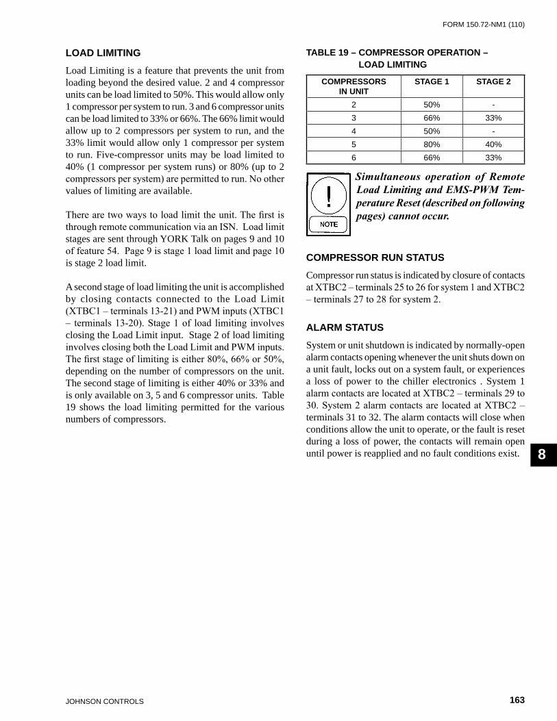
FORm 150.72-nm1 (110)
163JOHnSOn COnTROLS
8
LOAD LIMITING
Load Limiting is a feature that prevents the unit from loading beyond the desired value. 2 and 4 compressor units can be load limited to 50%. This would allow only 1 compressor per system to run. 3 and 6 compressor units can be load limited to 33% or 66%. The 66% limit would allow up to 2 compressors per system to run, and the 33% limit would allow only 1 compressor per system to run. Five-compressor units may be load limited to 40% (1 compressor per system runs) or 80% (up to 2 compressors per system) are permitted to run. No other values of limiting are available.
There are two ways to load limit the unit. The first is through remote communication via an ISN. Load limit stages are sent through YORK Talk on pages 9 and 10 of feature 54. Page 9 is stage 1 load limit and page 10 is stage 2 load limit.
A second stage of load limiting the unit is accomplished by closing contacts connected to the Load Limit (XTBC1 – terminals 13-21) and PWM inputs (XTBC1 – terminals 13-20). Stage 1 of load limiting involves closing the Load Limit input. Stage 2 of load limiting involves closing both the Load Limit and PWM inputs. The first stage of limiting is either 80%, 66% or 50%, depending on the number of compressors on the unit. The second stage of limiting is either 40% or 33% and is only available on 3, 5 and 6 compressor units. Table 19 shows the load limiting permitted for the various numbers of compressors.
Simultaneous operation of Remote Load Limiting and EMSPWM Tem-perature Reset (described on following pages) cannot occur.
COMPRESSOR RUN STATUS
Compressor run status is indicated by closure of contacts at XTBC2 – terminals 25 to 26 for system 1 and XTBC2 – terminals 27 to 28 for system 2.
ALARM STATUS
System or unit shutdown is indicated by normally-open alarm contacts opening whenever the unit shuts down on a unit fault, locks out on a system fault, or experiences a loss of power to the chiller electronics . System 1 alarm contacts are located at XTBC2 – terminals 29 to 30. System 2 alarm contacts are located at XTBC2 – terminals 31 to 32. The alarm contacts will close when conditions allow the unit to operate, or the fault is reset during a loss of power, the contacts will remain open until power is reapplied and no fault conditions exist.
COMPRESSORSIN UNIT
STAGE 1 STAGE 2
2 50% -3 66% 33%4 50% -5 80% 40%6 66% 33%
TABLE 19 – COMPRESSOR OPERATION – LOAD LIMITING
JOHnSOn COnTROLS164
FORm 150.72-nm1 (110)Unit Operation
BAS/EMS TEMPERATURE RESET USING A VOLTAGE OR CURRENT SIGNAL
The Remote Reset Option allows the Control Center of the unit to reset the chilled liquid setpoint using a 0 - 10VDC input, or a 4-20mA input connected to XTBC1 terminals A- and A+. Whenever a reset is called for, the change may be noted by pressing the COOLING SETPOINTS key twice. The new value will be displayed as “REM SETP = XXX °F.”
If a 0 - 10VDC signal is supplied, it is applied to terminals A+ and A-, and jumper JP1 on the I/O board must be inserted between pins 2 and 3. To calculate the reset chilled liquid setpoint for values between 0VDC and 10VDC use the following formula:
Setpoint = Local Chilled Liquid Setpoint + °Reset
°Reset = (DC voltage signal) x (*Max Reset Value) 10Example:Local Chilled Liquid Setpoint = 45 °F (7.22 °C)*Max Reset Value = 20 °F (11.11 °C)Input Signal = 6VDC
(English)°Reset = 6VDC x 20 °F = 12 °F Reset 10New Setpoint = 45 °F + 12 °F = 57 °F
(Metric)°Reset = 6VDC x 11. 11 °C = 6.67 °C Reset 10New Setpoint = 7.22 °C + 6.67 °C = 13.89 °C
* max Reset value is the “max EmS-PWm Remote Temp. Reset” setpoint value described in the program ming section under Cooling Setpoints. Programmable values are from 2 °F to 40 °F (1.11 °C to 11.11 °C).
If a 4-20mA signal is supplied, it is applied to terminals A+ and A- and jumper JP1 on the I/O board must be installed between pin 1 and 2. To calculate the chilled liquid setpoint for values between 4mA and 20 mA use the following formula:
Setpoint = Local Chilled Liquid Setpoint + °Reset
°Reset = (mA signal - 4) x (*Max Reset Value) 16Example:Local Chilled Liquid Setpoint = 45° (7.22 °C)*Max Reset Value = 10 °F (5.56 °C)Input Signal = 12 mA
(English)°Reset = 8mA x 10 °F = 5 °F Reset 16Setpoint = 45 °F + 5 °F = 50 °F
(Metric)°Reset = 8mA x 5.56 °C = 2.78 °C Reset 16Setpoint = 7.22 °C + 2.78 °C = 10.0 °C
A 24024 Volt Ratio Transformer (T3) is used to derive nominal 12 volt output from the 120 volt supply.

FORm 150.72-nm1 (110)
165JOHnSOn COnTROLS
9
SYS 1 HGBP STATUS TB7-7 IS:SYS 2 COMP 1 STATUS TB10-2 IS:
SYS 2 LLSV STATUS TB10-3 IS:SYS 2 COMP 2 STATUS TB10-4 IS:SYS 2 COMP 3 STATUS TB10-5 IS:
SYS 1 FAN OUTPUT 1 TB7-8 IS:SYS 1 FAN OUTPUT 2 TB7-9 IS:SYS 1 FAN OUTPUT 3 TB7-10 IS:SYS 2 FAN OUTPUT 1 TB10-8 IS:SYS 2 FAN OUTPUT 2 TB10-9 IS:SYS 2 FAN OUTPUT 3 TB10-10 IS:EVAP HEATER STATUS TB8-2 IS:SYS 1 ALARM STATUS TB8-3 IS:SYS 2 ALARM STATUS TB9-2 IS:EVAP PUMP STATUS TB8-6,7 IS:SYS 2 HGBV STATUS TB10-7 IS:
SPARE DO TB8-4 IS:SPARE DO TB8-5 IS:
SPARE DO TB8-8, 9 IS:SPARE DO TB9-4 IS:
SYS 1 EEV OUTPUT TB5-1, 2 = XXX%SYS 2 EEV OUTPUT TB6-1, 2 = XXX%
SYS 1 COND FAN SPEED J15-1,5 = XXX%SYS 2 COND FAN SPEED J15-2,6 = XXX%
SPARE AO J15-3,7 = XXX%SPARE AO J15-4,8 = XXX%
DATA LOGGING MODE 1 = ON, 0 = OFFDATA LOGGING TIMER X SECS
SOFT START (disabled)REFRIGERANT TYPE (R410A only)
EXPANSION VALVE TYPE (Thermostatic Only)REMOTE TEMP RESET OPTION = REMOTE INPUT SERVICE TIME =
“NORTH AMERICAN FEATURE SET ENABLED”HYDRO PUMP SELECTION
EVAP PUMP TOTAL RUN HOURSSYS 1 HOURSSYS 2 HOURSSYS 1 STARTSSYS 2 STARTS
Each display will also show the output connection on the microboard for the respective output status shown. For example:
This display indicates that the system 1 liquid line solenoid valve is OFF, and the output connection from the microboard is coming from Terminal Block 10 – pin 3.
S Y S 1 L L S V S T A T U S T B 10 - 3 I S O F F
SECTION 9 – SERVICE AND TROUBLESHOOTINGCLEARING HISTORY BUFFERS
The history buffers may be cleared by pressing the HISTORY key and then repeatedly pressing the UP arrow key until you scroll past the last history buffer choice. The following message will be displayed:
Pressing the ENTER/ADV key at this display will cause the history buffers to be cleared. Pressing any other key will cancel the operation.
DO NOT CLEAR BUFFERS. Impor-tant information may be lost. Contact factory service.
SERVICE MODE
Service Mode is a mode that allows the user to enable or disable all of the outputs (except compressors) on the unit, change chiller configuration setup parameters and view all the inputs to the microboard.
To enter Service Mode, turn the Unit Switch off and press the following keys in the sequence shown; PROGRAM, UP ARROW, UP ARROW, DOWN ARROW, DOWN ARROW, ENTER. Service Mode will time out after 30 minutes and return to normal control mode, if the panel is accidentally left in this mode. Otherwise, turning the unit switch on will take the panel out of Service Mode.
SERVICE MODE – OUTPUTS
After pressing the key sequence as described, the control will enter Service Mode permitting the outputs (except compressors), operating hours, refrigerant type, expansion valve type, and start/hour counters to be viewed/modified. The ENTER/ADV key is used to advance through the outputs. Using the ↑ and ↓ (UP/DOWN ) arrow keys will turn the respective digital output on/off or modify the value.
Following is the order of outputs that will appear as the ENTER/ADV key is pressed:
SYS 1 COMP 1 STATUS TB7-2 IS:SYS 1 LLSV STATUS TB7-3 IS:
SYS 1 COMP 2 STATUS TB7-4 IS:SYS 1 COMP 3 STATUS TB7-5 IS:
I I N I T I A L I Z E H I S T O R Y E N T E R = Y E S
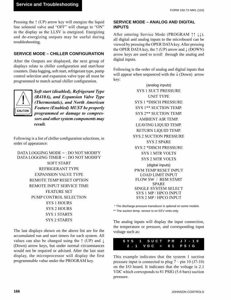
JOHnSOn COnTROLS166
FORm 150.72-nm1 (110)
Service and Troubleshooting
Pressing the ↑ (UP) arrow key will energize the liquid line solenoid valve and “OFF” will change to “ON” in the display as the LLSV is energized. Energizing and de-energizing outputs may be useful during troubleshooting.
SERVICE MODE – CHILLER CONFIGURATION
After the Outputs are displayed, the next group of displays relate to chiller configuration and start/hour counters. Data logging, soft start, refrigerant type, pump control selection and expansion valve type all must be programmed to match actual chiller configuration.
Soft start (disabled), Refrigerant Type (R410A), and Expansion Valve Type (Thermostatic), and North American Feature (Enabled) MUST be properly programmed or damage to compres-sors and other system components may result.
Following is a list of chiller configuration selections, in order of appearance:
DATA LOGGING MODE = : DO NOT MODIFYDATA LOGGING TIMER = : DO NOT MODIFY
SOFT STARTREFRIGERANT TYPE
EXPANSION VALVE TYPEREMOTE TEMP RESET OPTIONREMOTE INPUT SERVICE TIME
FEATURE SETPUMP CONTROL SELECTION
SYS 1 HOURSSYS 2 HOURSSYS 1 STARTSSYS 2 STARTS
The last displays shown on the above list are for the accumulated run and start timers for each system. All values can also be changed using the ↑ (UP) and ↓ (Down) arrow keys, but under normal circumstances would not be required or advised. After the last start display, the microprocessor will display the first programmable value under the PROGRAM key.
SERVICE MODE – ANALOG AND DIGITAL INPUTS
After entering Service Mode (PROGRAM ↑↑ ↓↓), all digital and analog inputs to the microboard can be viewed by pressing the OPER DATA key. After pressing the OPER DATA key, the ↑ (UP) arrow and ↓ (DOWN) arrow keys are used to scroll through the analog and digital inputs.
Following is the order of analog and digital inputs that will appear when sequenced with the ↓ (Down) arrow key:
(analog inputs)SYS 1 SUCT PRESSURE
UNIT TYPESYS 1 *DISCH PRESSURESYS 1** SUCTION TEMP. SYS 2** SUCTION TEMP.
AMBIENT AIR TEMP.LEAVING LIQUID TEMP.RETURN LIQUID TEMP.
SYS 2 SUCTION PRESSURESYS 2 SPARE
SYS 2 *DISCH PRESSURESYS 1 MTR VOLTSSYS 2 MTR VOLTS
(digital inputs)PWM TEMP RESET INPUT
LOAD LIMIT INPUTFLOW SW / REM START
SPARESINGLE SYSTEM SELECTSYS 1 MP / HPCO INPUTSYS 2 MP / HPCO INPUT
* The discharge pressure transducer is optional on some models.** The suction temp. sensor is on EEv units only.
The analog inputs will display the input connection, the temperature or pressure, and corresponding input voltage such as:
This example indicates that the system 1 suction pressure input is connected to plug 7 – pin 10 (J7-10) on the I/O board. It indicates that the voltage is 2.1 VDC which corresponds to 81 PSIG (5.6 bars) suction pressure.
S Y S 1 S U C T P R J 7 - 1 0 2 . 1 V D C = 8 1 P S I G

FORm 150.72-nm1 (110)
167JOHnSOn COnTROLS
9
TABLE 23 – I/O ANALOG OUTPUTS
TABLE 22 – I/O ANALOG INPUTS
The digital inputs will display the input connection and ON/OFF status such as:
This indicates that the flow switch/remote start input is connected to plug 13- pin 5 (J13-5) on the microboard, and is ON (ON = +30VDC unregulated input, OFF = 0VDC input on digital inputs).
CONTROL INPUTS/OUTPUTS
Tables 20 through 23 are a quick reference list providing the connection points and a description of the inputs and outputs respectively. All input and output connections pertain to the connections at the microboard.
F L O W S W / R E M S T A R T J 13 - 5 I S O N
TABLE 20 – I/O DIGITAL INPUTSJ13-2 Unit On/OFF SwitchJ13-3 Load Limit Stage 2 on 3, 5 & 6 Comp. UnitsJ13-4 Load Limit Stage 1J13-5 Flow Switch and Remote Start/StopJ13-6 Spare
J13-7 Single System Select(Jumper = Single Sys, no Jumper = Two Sys)
J13-8 CR1 (Sys 1 motor Protector/High Pressure Cutout)
J13-10 CR2(Sys 2 motor Protector/High Pressure Cutout)
J7-10SYS 1 Suction Transducer -or-SYS 1 Low Pressure Switch
J11-12Unit Type: Chiller = nO Jumper J11-12 to +24 vDCYCUL Condensing Unit = Jumper J11-12 to +24 vDC (Do nOT Use)
J7-11 SYS 1 Discharge Pressure Transducer (Optional)J6-9 Ambient Air Temp. SensorJ6-7 Leaving Chilled Liquid Temp. SensorJ6-8 Return Chilled Liquid Temp. Sensor
J9-10SYS 2 Suction Pressure Transducer-or-SYS 2 Low Pressure Switch
J9-11 SYS 2 Discharge Pressure Transducer(Optional)
J7-12 Unit/SYS 1 voltageJ9-12 SYS 2 voltageJ11-11 Remote Temperature Reset
TABLE 21 – I/O DIGITAL OUTPUTSTB7-2 SYS 1 Compressor 1 TB7-3 SYS 1 Liquid Line Solenoid ValveTB7-4 SYS 1 Compressor 2TB7-5 SYS 1 Compressor 3TB7-7 SYS 1 Hot Gas Bypass valve
TB10-2 SYS 2 Compressor 1TB10-3 SYS 2 Liquid Line Solenoid ValveTB10-4 SYS 2 Compressor 2TB10-5 SYS 2 Compressor 3TB7-8 SYS 1 Condenser Fan Output 1TB7-9 SYS 1 Condenser Fan Output 2TB7-10 SYS 1 Condenser Fan Output 3TB10-8 SYS 2 Condenser Fan Output 1TB10-9 SYS 2 Condenser Fan Output 2
TB10-10 SYS 2 Condenser Fan Output 3TB8-2 Evaporator HeaterTB8-3 SYS 1 AlarmTB9-2 SYS 2 Alarm
TB8-6 & 7 Evaporator Pump StarterTB10-7 SYS 2 Hot Gas Bypass valve
N/A not Applicable

JOHnSOn COnTROLS168
FORm 150.72-nm1 (110)
Service and Troubleshooting
FIG. 29 – MICROBOARD LAYOUT
TB5
TB1
TB6
TB7
TB8
TB9
TB10
J14 J13J12
J15
J11
J10
J9
J8
J7
J6
J5
J3
I/O BOARD
IPU BOARD
JP1
LD12721
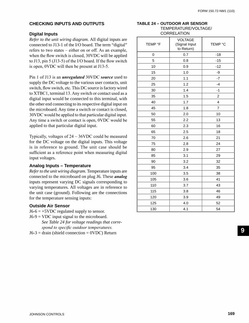
FORm 150.72-nm1 (110)
169JOHnSOn COnTROLS
9
CHECKING INPUTS AND OUTPUTS
Digital InputsRefer to the unit wiring diagram. All digital inputs are connected to J13-1 of the I/O board. The term “digital” refers to two states – either on or off. As an example, when the flow switch is closed, 30VDC will be applied to J13, pin 5 (J13-5) of the I/O board. If the flow switch is open, 0VDC will then be present at J13-5.
Pin 1 of J13 is an unregulated 30VDC source used to supply the DC voltage to the various user contacts, unit switch, flow switch, etc. This DC source is factory wired to XTBC1, terminal 13. Any switch or contact used as a digital input would be connected to this terminal, with the other end connecting to its respective digital input on the microboard. Any time a switch or contact is closed, 30VDC would be applied to that particular digital input. Any time a switch or contact is open, 0VDC would be applied to that particular digital input.
Typically, voltages of 24 – 36VDC could be measured for the DC voltage on the digital inputs. This voltage is in reference to ground. The unit case should be sufficient as a reference point when measuring digital input voltages.
Analog Inputs – TemperatureRefer to the unit wiring diagram. Temperature inputs are connected to the microboard on plug J6. These analog inputs represent varying DC signals corresponding to varying temperatures. All voltages are in reference to the unit case (ground). Following are the connections for the temperature sensing inputs:
Outside Air SensorJ6-6 = +5VDC regulated supply to sensor.J6-9 = VDC input signal to the microboard.
See Table 24 for voltage readings that corre-spond to specific outdoor temperatures.
J6-3 = drain (shield connection = 0VDC) Return
TABLE 24 – OUTDOOR AIR SENSOR TEmPERATURE/vOLTAGE/ CORRELATIOn
TEmP °FvOLTAGE
(Signal Inputto Return)
TEmP °C
0 0.7 -185 0.8 -15
10 0.9 -1215 1.0 -920 1.1 -725 1.2 -430 1.4 -135 1.5 240 1.7 445 1.8 750 2.0 1055 2.2 1360 2.3 1665 2.5 1870 2.6 2175 2.8 2480 2.9 2785 3.1 2990 3.2 3295 3.4 35
100 3.5 38105 3.6 41110 3.7 43115 3.8 46120 3.9 49125 4.0 52130 4.1 54

JOHnSOn COnTROLS170
FORm 150.72-nm1 (110)
Service and Troubleshooting
Liquid & Refrigerant Sensor Test Points (Table 25)
Entering Chilled Liquid Sensor
J6-5 = +5VDC regulated supply to sensor.J6-8 = VDC input signal to the I/O board. See Table 25
for voltage readings that correspond to specific liquid temperatures.
J6-2 = drain (shield connection = 0VDC) Return
Leaving Chilled Liquid Temperature Sensor
J6-4 = +5VDC regulated supply to sensor.J6-7 = VDC input signal to the microboard. See Table
25 for voltage readings that correspond to specific liquid temperatures.
J6-1 = drain (shield connection = 0VDC) Return
TABLE 25 – ENTERING/LEAVING CHILLED LIQUID TEMP. SENSOR, TEMPERATURE/VOLTAGE CORRELATION
TEmP °FvOLTAGE
(Signal Inputto Return)
TEmP °C
10 1.33 -1212 1.39 -1114 1.46 -1016 1.51 -918 1.58 -820 1.65 -722 1.71 -624 1.78 -426 1.85 -328 1.91 -230 1.98 -132 2.05 034 2.12 136 2.19 238 2.26 340 2.33 442 2.40 644 2.47 746 2.53 848 2.60 950 2.65 1052 2.73 1154 2.80 1256 2.86 1358 2.92 1460 2.98 1662 3.05 1764 3.11 1866 3.17 1968 3.23 2070 3.29 2172 3.34 2274 3.39 2376 3.45 2478 3.5 2680 3.54 27
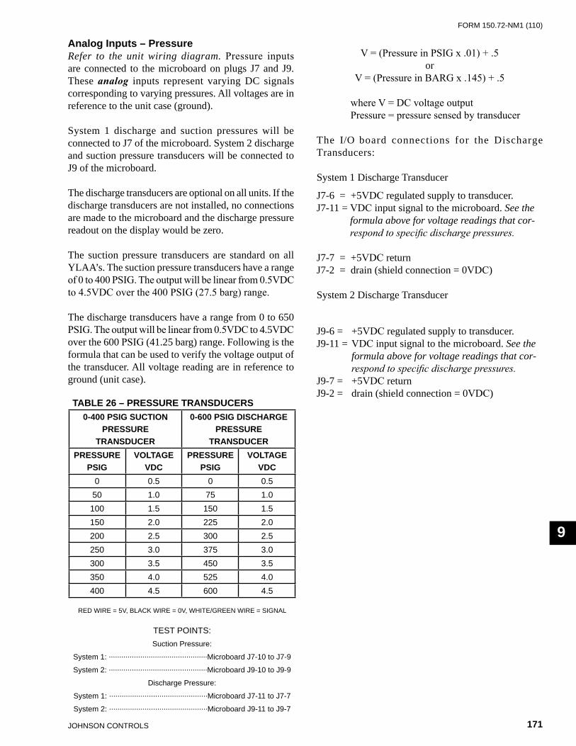
FORm 150.72-nm1 (110)
171JOHnSOn COnTROLS
9
Analog Inputs – PressureRefer to the unit wiring diagram. Pressure inputs are connected to the microboard on plugs J7 and J9. These analog inputs represent varying DC signals corresponding to varying pressures. All voltages are in reference to the unit case (ground).
System 1 discharge and suction pressures will be connected to J7 of the microboard. System 2 discharge and suction pressure transducers will be connected to J9 of the microboard.
The discharge transducers are optional on all units. If the discharge transducers are not installed, no connections are made to the microboard and the discharge pressure readout on the display would be zero.
The suction pressure transducers are standard on all YLAA’s. The suction pressure transducers have a range of 0 to 400 PSIG. The output will be linear from 0.5VDC to 4.5VDC over the 400 PSIG (27.5 barg) range.
The discharge transducers have a range from 0 to 650 PSIG. The output will be linear from 0.5VDC to 4.5VDC over the 600 PSIG (41.25 barg) range. Following is the formula that can be used to verify the voltage output of the transducer. All voltage reading are in reference to ground (unit case).
V = (Pressure in PSIG x .01) + .5or
V = (Pressure in BARG x .145) + .5
where V = DC voltage output Pressure = pressure sensed by transducer
The I/O board connections for the Discharge Transducers:
System 1 Discharge Transducer
J7-6 = +5VDC regulated supply to transducer.J7-11 = VDC input signal to the microboard. See the
formula above for voltage readings that cor-respond to specific discharge pressures.
J7-7 = +5VDC returnJ7-2 = drain (shield connection = 0VDC)
System 2 Discharge Transducer
J9-6 = +5VDC regulated supply to transducer.J9-11 = VDC input signal to the microboard. See the
formula above for voltage readings that cor-respond to specific discharge pressures.
J9-7 = +5VDC returnJ9-2 = drain (shield connection = 0VDC)
TABLE 26 – PRESSURE TRANSDUCERS0-400 PSIG SUCTION
PRESSURE TRANSDUCER
0-600 PSIG DISCHARGE PRESSURE
TRANSDUCERPRESSURE
PSIGVOLTAGE
VDCPRESSURE
PSIGVOLTAGE
VDC0 0.5 0 0.550 1.0 75 1.0100 1.5 150 1.5150 2.0 225 2.0200 2.5 300 2.5250 3.0 375 3.0300 3.5 450 3.5350 4.0 525 4.0400 4.5 600 4.5
RED WIRE = 5v, BLACK WIRE = 0v, WHITE/GREEn WIRE = SIGnAL
TEST POInTS:Suction Pressure:
System 1: ...............................................microboard J7-10 to J7-9
System 2: ...............................................microboard J9-10 to J9-9
Discharge Pressure:
System 1: ...............................................microboard J7-11 to J7-7
System 2: ...............................................microboard J9-11 to J9-7

JOHnSOn COnTROLS172
FORm 150.72-nm1 (110)
Service and Troubleshooting
FIG. 30 – I/O BOARD RELAY CONTACT ARCHITECTURE
LD12722
The suction transducers have a range from 0 to 400 PSIG (27.5 barg). The output will be linear from 0.5VDC to 4.5VDC over the 400 PSIG (27.5 barg) range. Following is a formula that can be used to verify the voltage output of the transducer. All voltage reading are in reference to ground (unit case).
v = (Pressure in PSIG x .02) + .5or
v = (Pressure in barg x .29) + .5
where v = DC voltage input to microprocessor Pressure = pressure sensed by transducer
Following are the I/O board connections for the Suction Transducer:
System 1 Suction Transducer
J7-5 = +5VDC regulated supply to transducer.J7-10 = VDC input signal to the microboard. See the formula above for voltage readings that cor-respond to specific suction pressures.J7-9 = +5VDC returnJ7-1 = drain (shield connection = 0VDC)
System 2 Suction Transducer
J9-5 = +5VDC regulated supply to transducer.J9-10 = VDC input signal to the microboard. See the formula above for voltage readings that cor-respond to specific suction pressures.J7-9 = +5VDC returnJ7-11 = drain (shield connection = 0VDC)
Digital OutputsRefer to the unit wiring diagram and Fig. 30. The digital outputs are located on TB7, TB8, and TB9 and TB-10 of the microboard. ALL OUTPUTS ARE 120VAC with the exception of TB8-6 to TB8-7 which are the contacts that can be used for a remote evaporator pump start signal. The voltage applied to either of these terminals would be determined by field wiring.
Each output is controlled by the microprocessor by switching 120VAC to the respective output connection energizing contactors, evaporator heater, and solenoids according to the operating sequence (see Fig. 30).
120VAC is supplied to the I/O board via connections at TB7-1, TB7-6, TB10-1, TB10-6, TB8-1 and TB9-1. Fig. 30 illustrates the relay contact architecture on the microboard.
SYS 1COMP 1TB7-2
SYS 1COMP 2TB7-4
SYS 1COMP 3TB7-5
TB7-3 LLSV 1
TB8-6 EVAP PUMPTB8-7
TB7
SYS 2HGSVTB10-7
SYS 2FAN 2
TB10-8
TB10-9
TB10-10 SYS 2FAN 4
TB10
TB8
TB10
SYS 2COMPR 1 (4)TB10-2
LLSV 2TB10-3
SYS 2COMPR 2 (5)TB10-4
SYS 2COMPR 3 (6)TB10-5
TB7
SYS 1HGSVTB7-7
SYS 1FAN 1TB7-9
SYS 1FAN 3TB7-10
TB7-8 SYS 1FAN 2
TB8-2 HEAT EXCH HEATER

FORm 150.72-nm1 (110)
173JOHnSOn COnTROLS
9
LD12723
The micro panel is capable of supplying a printout of chiller conditions or fault shutdown information at any given time. This allows operator and service personnel to obtain data and system status with the touch of the keypad. In addition to manual print selection, the micro panel will provide an automatic printout whenever a fault occurs. Detailed explanation of the print function is given under “Print Key” located in the “Keypad and Display” section.
Johnson Controls recommends the field tested WEIGH-TRONIX model 1220 printer (or former IMP 24). This is a compact low cost printer that is ideal for service work and data logging.
The WEIGH-TRONIX printer can be obtained by contacting WEIGH-TRONIX for purchase information at:
WEIGH-TRONIX2320 Airport Blvd.Santa Rosa, CA 95402Phone: 1-800-982-6622 or 1-707-527-5555 (International Orders Only)
The part number for the printer that is packaged specifically for YORK is P/N 950915576. The cable to connect the printer can either be locally assembled from the parts listed, or ordered directly from WEIGH-TRONIX under part number 287-040018.
PartsThe following parts are required:
1. WEIGH-TRONIX model 1220 printer. 2. 2.25” (5.7cm) wide desk top calculator paper. 3. 25 ft. (7.62m) maximum length of Twisted Pair
Shielded Cable (minimum 3 conductor), #18 AWG stranded, 300V minimum insulation.
4. One 25 pin Cannon connector and shell. Connector: Cannon P/N DB-25P or equivalent.
Shell: Cannon P/N DB-C2-J9.
Assembly and WiringAll components should be assembled and wired as shown in Fig. 31. Strip the outside insulation back several inches and individual wires about 3/8” (9.5 mm) to connect the cable at the Microboard. Do not connect the shield at the printer-end of the cable.
Obtaining a PrintoutA printout is obtained by pressing the PRINT key on the keypad and then pressing either the OPER DATA key or HISTORY key.
FIG. 31 – PRINTER TO MICROBOARD ELECTRICAL CONNECTIONS
OPTIONAL PRINTER INSTALLATION
TB3-3 TXD
TB3-2 CTS
TB3-5 GND
TB3
2 RD
7 SG
5 CTS
Chiller Microboard Printer
Do not connect shield at printer end.
Shield (connect shield to Pin 5 of the connector.
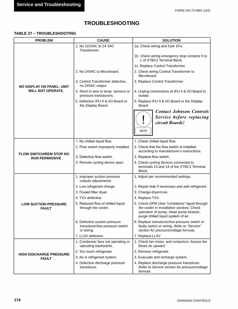
JOHnSOn COnTROLS174
FORm 150.72-nm1 (110)
Service and Troubleshooting
TROUBLESHOOTING
TABLE 27 – TROUBLESHOOTING
PROBLEM CAUSE SOLUTION
NO DISPLAY ON PANEL. UNIT WILL NOT OPERATE.
1. no 115vAC to 24 vAC Transformer.
1a. Check wiring and fuse 1FU.
1b. Check wiring emergency stop contacts 5 to L of XTBC2 Terminal Block.
1c. Replace Control Transformer.2. no 24vAC to microboard. 2. Check wiring Control Transformer to
microboard.3. Control Transformer defective,
no 24vAC output.3. Replace Control Transformer.
4. Short in wire to temp. sensors or pressure transducers.
4. Unplug connections at IPU II & I/O Board to isolate.
5. Defective IPU II & I/O Board or the Display Board.
5. Replace IPU II & I/O Board or the Display Board.
Contact Johnson Controls Service before replacing circuit Boards!
FLOW SWITCH/REM STOP NO RUN PERMISSIVE
1. No chilled liquid flow. 1. Check chilled liquid flow.2. Flow switch improperly installed. 2. Check that the flow switch is installed
according to manufacturer’s instructions.3. Defective flow switch. 3. Replace flow switch.4. Remote cycling device open. 4. Check cycling devices connected to
terminals 13 and 14 of the XTBC1 Terminal Block.
LOW SUCTION PRESSURE FAULT
1. Improper suction pressure cutouts adjustments.
1. Adjust per recommended settings.
2. Low refrigerant charge. 2. Repair leak if necessary and add refrigerant.3. Fouled filter dryer. 3. Change dryer/core.4. TXv defective. 4. Replace TXv.5. Reduced flow of chilled liquid
through the cooler.5. Check GPm (See “Limitations” liquid through
the cooler in Installation section). Check operation of pump, clean pump strainer, purge chilled liquid system of air.
6. Defective suction pressure transducer/low pressure switch or wiring.
6. Replace transducer/low pressure switch or faulty switch or wiring. Refer to “Service” section for pressure/voltage formula.
7. LLSv defective 7. Replace LLSv
HIGH DISCHARGE PRESSURE FAULT
1. Condenser fans not operating or operating backwards.
1. Check fan motor, and contactors. Assure fan blows air upward.
2. Too much refrigerant. 2. Remove refrigerant.3. Air in refrigerant system. 3. Evacuate and recharge system.4. Defective discharge pressure
transducer.4. Replace discharge pressure transducer.
Refer to Service section for pressure/voltage formula.

FORm 150.72-nm1 (110)
175JOHnSOn COnTROLS
9
TROUBLESHOOTING (CONT’D)
PROBLEM CAUSE SOLUTION
LOW LIQUID TEMP FAULT
1. Improperly adjusted leaving chilled liquid temp. cutout (glycol only).
1. Re-program the leaving chilled liquid temp. cutout.
2. micro panel setpoint/range values improperly programmed.
2. Re-adjust setpoint/range.
3. Chilled liquid flow too low. 3. Increase chilled liquid flow. Refer to Limitations in Installation section.
4. Defective LWT or RWT sensor (assure the sensor is properly installed in the bottom of the well with a generous amount of heat) conductive compound).
4. Compare sensor against a known good Temperature sensing device. Refer to Service section for temp./voltage table.
MP / HPCO FAULT
1. Compressor internal motor protector (mP) open.
1. verify refrigerant charge is not low. verify superheat setting of 10 °F to 15 °F (5.6 °C to 8.3 °C). verify correct compressor rotation. verify compressor is not overloaded.
2. External overload tripped. 2. Determine cause and reset.3. HPCO switch open. 3. See “High Press. Disch.” Fault.4. Defective HPCO switch. 4. Replace HPCO switch.5. Defective CR relay. 5. Replace relay.
COMPRESSOR(S) WON’T START
1. Demand not great enough. 1. no problem. Consult “Installation” Manual to aid in understanding compressor operation and capacity control.
2. Defective water temperature sensor.
2. Compare the display with a thermometer. Should be within +/- 2 degrees. Refer to Service section for RWT/LWT temp./voltage table.
3. Contactor/Overload failure. 3. Replace defective part.4. Compressor failure. 4. Diagnose cause of failure and replace.
LACK OF COOLING EFFECT
1. Fouled evaporator surface. Low suction pressure will be observed.
1. Contact the local Johnson Controls service representative.
2. Improper flow through the evaporator.
2. Reduce flow to within chiller design specs. See Limitations in Installation section.
3. Low refrigerant charge. Low suction pressure will be observed.
3. Check subcooling and add charge as needed.
TABLE 27 (cont’d) – TROUBLESHOOTING

JOHnSOn COnTROLS176
FORm 150.72-nm1 (110)
THIS PAGE INTENTIONALLY LEFT BLANK

FORm 150.72-nm1 (110)
177JOHnSOn COnTROLS
10
SECTION 10 – MAINTENANCE
It is the responsibility of the equipment owner to provide maintenance on the system.
IMPORTANT
If system failure occurs due to improper maintenance during the warranty period, Johnson Controls will not be liable for costs incurred to return the system to satisfactory operation. The following is intended only as a guide and covers only the chiller unit components. It does not cover other related system components which may or may not be furnished by Johnson Controls. System components should be maintained according to the individual manufacture’s recommendations as their operation will affect the operation of the chiller.
COMPRESSORS
Oil Level CheckThe oil level can only be tested when the compressor is running in stabilized conditions, to ensure that there is no liquid refrigerant in the lower shell of the compressor. When the compressor is running at stabilized conditions, the oil level must be between 1/4 and 3/4 in the oil sight glass. Note: at shutdown, the oil level can fall to the bottom limit of the oil sight glass. Use YORK “V” oil when adding oil.
Oil AnalysisThe oil used in these compressors is pale yellow in color (POE oil). If the oil color darkens or exhibits a change in color, this may be an indication of contaminants in the refrigerant system. If this occurs, an oil sample should be taken and analyzed. If contaminants are present, the system must be cleaned to prevent compressor failure.
Never use the scroll compressor to pump the refrigerant system down into a vac-uum. Doing so will cause internal arcing of the compressor motor which will re-sult in failure of compressor.
CONDENSER FAN MOTORS
Condenser fan motors are permanently lubricated and require no maintenance.
CONDENSER COILS
Dirt should not be allowed to accumulate on the condenser coil surfaces. Cleaning should be as often as necessary to keep coils clean.
Exercise care when cleaning the coil so that the coil fins are not damaged.
OPERATING PARAMETERS
Regular checks of the system should be preformed to ensure that operating temperatures and pressures are within limitations, and that the operating controls are set within proper limits. Refer to the Operation, Start-Up, and Installation sections of this manual.
ON-BOARD BATTERY BACK-UP
U5 is the Real Time Clock chip located on the 031-02630 IPU II board that maintains the date/time and stores customer programmed setpoints. The Real Time Clock is a 128K bram, P/N 031-02565-000. The IPU II board must have JP1 installed when the 128K bram is installed.
Do not confuse JP1 on the IPU II (03102630) board with JP1 on the I/O (03102550) board.
EVAPORATOR HEATER
The internal power supply to the Evaporator Heater is 120VAC. Dis-connecting 120VAC power from the unit, at or below freezing temperatures, can result in damage to the evaporator and unit as a result of the chilled liquid freezing.
OVERALL UNIT INSPECTION
In addition to the checks listed on this page, periodic overall inspections of the unit should be accomplished to ensure proper equipment operation. Items such as loose hardware, component operation, refrigerant leaks, unusual noises, etc. should be investigated and corrected immediately.

JOHnSOn COnTROLS178
FORm 150.72-nm1 (110)Maintenance
BACNET, MODBUS AND YORKTALK 2 COM-MUNICATIONS
Data can be read and in some cases modified using a serial communication BACnet, Modbus or YorkTalk 2 network connection. This information allows communications of chiller operating parameters and external control changes to setpoint, load limiting, and start/stop commands.
BACnet and YorkTalk 2 RS485 networks are wired to the + and - terminals of TB1 for port 1 communications. Modbus network connection has the option of RS232 or RS485 connection for port 2 communications. Modbus network is wired to either TB2 or TB3 as follows:
• RS-485: connect to TB2 - Network (-1) to TB2 (-1); Network (+1) to TB2 (+1)
• RS-232: connect to TB3 - Network (RX) to TB3 (TXD); Network (TX) to TB3 (RXD); Network (GND) to TB3 (GND)
Refer to Fig. 32 “Micro Panel Connections” for TB1, TB2 and TB3 locations.
In most cases, communication parameters will need to be modified. Table 29 “Values Required for BAS Communication” lists setup parameters for the available protocols. Modification is accomplished by pressing the PROGRAM, DOWN ARROW, DOWN ARROW, DOWN ARROW, DOWN ARROW, and ENTER keys in sequence. The list below shows the displays for the values that may be modified:
DE mODIFIER ADDRESSXXXXX
DE mODIFIER OFFSETXX
P1 PROTOCOLXXXXXX
P1 mAnUAL mACADDRESS XXX
P1 BAUD RATEXXXXX
P1 PARITYXXXXX
P1 STOP BITSX
P2 PROTOCOLXXXXXXXXXX
P2 mAnUAL mACADDRESS XXX
P2 BAUD RATEXXXXX
P2 PARITYXXXXX
P2 STOP BITSX
P2 HW SELECT BIT XXXXX
REAL TImE ERROR ##RESET 1 = YES, 0 = nO 0
note: See Table 30 for error descriptions
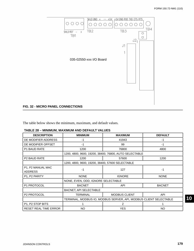
FORm 150.72-nm1 (110)
179JOHnSOn COnTROLS
10
The table below shows the minimum, maximum, and default values.
TABLE 28 – MINIMUM, MAXIMUM AND DEFAULT VALUESDESCRIPTION MINIMUM MAXIMUM DEFAULT
DE mODIFIER ADDRESS -1 41943 -1DE mODIFIER OFFSET -1 99 -1P1 BAUD RATE 1200 76800 4800
1200, 4800, 9600, 19200, 38400, 76800, AUTO SELECTABLEP2 BAUD RATE 1200 57600 1200
1200, 4800, 9600, 19200, 38400, 57600 SELECTABLEP1, P2 mAnUAL mAC ADDRESS
-1 127 -1
P1, P2 PARITY nOnE IGnORE nOnEnOnE, EvEn, ODD, IGnORE SELECTABLE
P1 PROTOCOL BACnET API BACnETBACnET, API SELECTABLE
P2 PROTOCOL TERmInAL mODBUS CLIEnT APITERmInAL, mODBUS IO, mODBUS SERvER, API, mODBUS CLIEnT SELECTABLE
P1, P2 STOP BITS 1 2 1RESET REAL TImE ERROR nO YES nO
035-02550-xxx I/O Board
FIG. 32 - MICRO PANEL CONNECTIONS
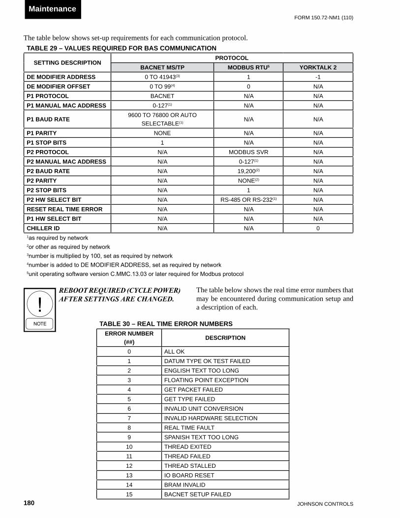
JOHnSOn COnTROLS180
FORm 150.72-nm1 (110)Maintenance
TABLE 30 – REAL TIME ERROR NUMBERSERROR NUMBER
(##)DESCRIPTION
0 ALL OK1 DATUm TYPE OK TEST FAILED2 EnGLISH TEXT TOO LOnG3 FLOATInG POInT EXCEPTIOn4 GET PACKET FAILED5 GET TYPE FAILED6 InvALID UnIT COnvERSIOn7 InvALID HARDWARE SELECTIOn8 REAL TImE FAULT9 SPAnISH TEXT TOO LOnG10 THREAD EXITED11 THREAD FAILED12 THREAD STALLED13 IO BOARD RESET14 BRAm InvALID15 BACnET SETUP FAILED
TABLE 29 – VALUES REQUIRED FOR BAS COMMUNICATION
SETTING DESCRIPTIONPROTOCOL
BACNET MS/TP MODBUS RTU5 YORKTALK 2DE MODIFIER ADDRESS 0 TO 41943(3) 1 -1DE MODIFIER OFFSET 0 TO 99(4) 0 n/AP1 PROTOCOL BACnET n/A n/AP1 MANUAL MAC ADDRESS 0-127(1) n/A n/A
P1 BAUD RATE9600 TO 76800 OR AUTO
SELECTABLE(1)n/A n/A
P1 PARITY nOnE n/A n/AP1 STOP BITS 1 n/A n/AP2 PROTOCOL n/A mODBUS SvR n/AP2 MANUAL MAC ADDRESS n/A 0-127(1) n/AP2 BAUD RATE n/A 19,200(2) n/AP2 PARITY n/A nOnE(2) n/AP2 STOP BITS n/A 1 n/AP2 HW SELECT BIT n/A RS-485 OR RS-232(1) n/ARESET REAL TIME ERROR n/A n/A n/AP1 HW SELECT BIT n/A n/A n/ACHILLER ID n/A n/A 01as required by network2or other as required by network3number is multiplied by 100, set as required by network4number is added to DE MODIFIER ADDRESS, set as required by network5unit operating software version C.MMC.13.03 or later required for Modbus protocol
The table below shows set-up requirements for each communication protocol.
The table below shows the real time error numbers that may be encountered during communication setup and a description of each.
REBOOT REQUIRED (CyCLE POWER) AFTER SETTINGS ARE CHANGED.
FORm 150.72-nm1 (110)
181JOHnSOn COnTROLS
10
BACnet and Modbus CommunicationsChiller data that can be read and modified using specific BACnet or Modbus Register Addresses; and the data associated with the addresses, is outlined in the following description:
Analog Write Points
This data can be read and modified using a BACnet or Modbus network connection. The Modbus Register Address for these points is 1025 + AV #.
Binary Write Points
This data can be read and modified using a BACnet or Modbus network connection. The Modbus Register Address for these points is 1537 + BV #.
Analog Read Only Points
This data can be read using a BACnet or Modbus network connection and can NOT be modified using this connection. The Modbus Register Address for these points is 513 + AI #.
Binary Monitor Only Points
This data can be read using a BACnet or Modbus network connection and can NOT be modified using this connection. The Modbus Register Address for these points is 1281 + BI #.
Refer to Table 31 for complete list of BACnet and Modbus registers.
The latest data map information is listed on the Johnson Controls Equip-ment Integration website.
Communications Data Map Notes(See Table 31)
1. IPU II based units are configured for Native BACnet
MS/TP and Modbus RTU communications. Microgateway or E-Link not required for these two communication protocols.
2. BACnet Object Types: 0= Analog In, 1 = Analog Out, 2= Analog Value, 3= Bina-ry In, 4 = Binary Output, 5= Binary Value, 8= Device, 15 = Alarm Notification (0 through 127 are reserved ASHRAE Objects).
3. WC= Inches of water column; CFM = Cubic Feet per Minute; FPM = Feet per Minute: PSI = Lbs per square inch; Pa = Pascals; kPa = Kilopascals; PPM = Part per Million; kJ/kg = Kilojoules per Kilogram.
4. Water Cooled Scroll units use the same firmware as Air Cooled Scroll units, ignoring Fan Control.

JOHnSOn COnTROLS182
FORm 150.72-nm1 (110)Maintenance
TABLE 31 - BACNET AND MODBUS COMMUNICATIONS DATA MAP
2/25
/200
9
Nat
ive
ITEM
Vers
ion
Dat
eC
heck
Sum
1C
.mm
C.1
3.00
29-n
ov-0
62
C.m
mC
.15.
0029
-nov
-06
3C
.mm
C.1
4.00
29-n
ov-0
64
C.m
mC
.16.
0029
-nov
-06
5C
.mm
C.1
3.02
17-O
ct-0
86
C.m
mC
.14.
0217
-Oct
-08
7C
.mm
C.1
6.02
17-O
ct-0
88 9 10
12
34
56
78
910
1SE
E n
OTE
5SE
E N
OTE
13 4
REm
_SET
PAv
_110
2603
,06,
16F°
R/W
Setp
oint
Coo
ling
Set
poin
t(HP
Onl
y), 9
9 =
Auto
; (40
°F -
70°F
)5
SP_R
Em_S
P_S1
Av_2
1027
03,0
6,16
PSIG
R/W
Sys
1 Se
tpoi
nt (
Suct
ion
Pres
sure
Con
trol u
nits
onl
y)
6LO
AD_L
ImIT
Av_3
1028
03,0
6,16
inde
xR
/WLo
ad L
imit
Stag
e (0
, 1, 2
)7
REm
_CR
Av_4
1029
03,0
6,16
F °R
/WC
oolin
g R
ange
(DAT
mod
e O
nly)
8SP
_REm
_SP_
S2Av
_510
3003
,06,
16PS
IGR
/WSy
s 2
Setp
oint
(Suc
tion
Pres
sure
Con
trol)
9R
Em_S
P_H
EAT
Av_6
1031
03,0
6,16
F °R
/WH
eatin
g Se
tpoi
nt (H
P O
nly)
, 999
= A
uto
(95°
F - 1
22°F
)
10H
P_m
OD
EAv
_710
3203
,06,
16in
dex
R/W
mod
e (H
P O
nly)
(0=P
anel
, 1=C
oolin
g, 2
=Hea
ting)
11 12 13ST
ART_
STO
PBv
_115
3801
,03,
05,1
5,06
,16
0, 1
R/W
Stop
Sta
rt C
omm
and
14SS
_SYS
1Bv
_215
3901
,03,
05,1
5,06
,16
0, 1
R/W
Sys
1 S
tart/
Stop
( Su
ctio
n Pr
essu
re (S
P) C
ontro
l Onl
y)15
SS_S
YS2
Bv_3
1540
01,0
3,05
,15,
06,
0, 1
R/W
Sys
2 S
tart/
Stop
( Su
ctio
n Pr
essu
re (S
P) C
ontro
l Onl
y)
16 17LC
HLT
AI_1
514
03,0
4F °
RLe
avin
g C
hille
d Li
quid
Tem
p18
RC
HLT
AI_2
515
03,0
4F °
RR
etur
n C
hille
d Li
quid
Tem
p19
DAT
AI_3
516
03,0
4F °
RC
onde
nsin
g U
nit m
odel
s O
nly
20S1
_SU
CT_
TEm
PAI
_451
703
,04
F°R
Elec
troni
c Ex
pans
ion
valv
e m
odel
s O
nly
21O
ATAI
_551
803
,04
F °R
Ambi
ent A
ir Te
mpe
ratu
re22
S1_S
UC
T_SH
EAT
AI_6
519
03,0
4F °
RSy
s 1
Suct
ion
Supe
rhea
t ( E
Ev m
odel
s O
nly)
23
S1_R
Un
_TIm
EAI
_752
003
,04
seco
nds
RSy
s 1
Run
Tim
e (s
econ
ds)
24S1
_SU
CT_
PRAI
_852
103
,04
PSIG
RSy
s 1
Suct
ion
Pres
sure
25S1
_DSC
H_P
RAI
_952
203
,04
PSIG
RSy
s 1
Dis
char
ge P
ress
ure
27S1
_CIR
_TEm
PAI
_10
523
03,0
4F °
RSy
s 1
Coo
ler I
nlet
Ref
riger
ant T
emp
(R-4
07c
mod
els
Onl
y)28
S1_D
EF_T
EmP
AI_1
152
403
,04
F °R
Sys
1 D
efro
st T
empe
ratu
re (H
P O
nly)
29S1
_EEv
_OU
TAI
_12
525
03,0
4F °
RSy
stem
1 E
Ev O
utpu
t % (
EEv
mod
els
Onl
y)30
S1_A
R_T
ImER
AI_1
352
603
,04
seco
nds
RSy
s 1
Anti-
Rec
ycle
Tim
er31
AC_T
ImER
AI_1
452
703
,04
seco
nds
RAn
ti-C
oinc
iden
t Tim
er32
S2_S
UC
T_TE
mP
AI_1
552
803
,04
°FR
Syst
em 2
Suc
tion
Tem
p ( E
Evm
odel
s O
nly)
33S2
_RU
n_T
ImE
AI_1
652
903
,04
seco
nds
RSy
s 2
Run
Tim
e (s
econ
ds)
34S2
_SU
CT_
PRAI
_17
530
03,0
4PS
IGR
Sys
2 Su
ctio
n Pr
essu
re35
S2_D
SCH
_PR
AI_1
853
103
,04
PSIG
RSy
s 2
Dis
char
ge P
ress
ure
36S2
_CIR
_TEm
PAI
_19
532
03,0
4F °
RSy
s 2
Coo
ler I
nlet
Ref
riger
ant T
empe
ratu
re(R
-407
c O
nly)
37S2
_DEF
_TEm
PAI
_20
533
03,0
4F °
RSy
s 2
Def
rost
Tem
pera
ture
(HP
Onl
y)38
S2_S
UC
T_SH
AI_2
153
403
,04
F °R
Sys
2 Su
ctio
n Su
perH
eat (
EEv
mod
els
Onl
y)39
S2_A
R_T
ImER
AI_2
253
503
,04
F °R
Sys
2 An
ti-R
ecyc
le T
imer
40S2
_EEv
_OU
TAI
_23
536
03,0
4se
cond
sR
Sys
2 Su
ctio
n Su
perh
eat (
EEv
mod
els
Onl
y)
Boar
d: 0
31-0
2630
-xxx
w/ 0
31-0
2550
Mod
bus
and
BAC
net M
S/TP
Dat
a M
aps
YC
AL/
YC
UL/
YC
WL/
YLA
A I
PU
II
POIN
T D
ESC
RIP
TIO
NIT
Em R
EF
nU
mBA
Cne
t NAM
E
York
PN
Com
men
tsSt
anda
rd w
ith B
oard
: 031
-026
30-x
xx w
/ 031
-025
50Ba
sildo
n w
ith B
oard
: 031
-026
30-x
xx w
/ 031
-025
5003
1-02
755-
001
031-
0275
5-00
303
1-02
755-
004
031-
0275
5-00
2
Basil
don
MM
HP
with
Boa
rd: 0
31-0
2630
-xxx
w/ 0
31-0
2550
Fix
nat
ive
Mod
bus c
omm
unic
atio
ns. F
ix C
afé
Met
ric fu
nctio
nalit
y (S
CR-7
66)
BI
NAR
Y W
RIT
E P
OIN
TS
AN
ALO
G W
RIT
E P
OIN
TS
Poin
t Lis
t Cod
e S=
Stan
dard
; O
= O
ptio
nal;
n =
not
Ava
ilabl
e BA
Cne
t O
bjec
t/Ins
tan
ce
MM
HP
with
Boa
rd: 0
31-0
2630
-xxx
w/ 0
31-0
2550
Basil
don
MM
HP
with
Boa
rd: 0
31-0
2630
-xxx
w/ 0
31-0
2550
Stan
dard
mic
ro B
oard
031
-025
50-x
xx .
Fix
nat
ive
mod
bus
com
mun
icat
ions
. Fix
Caf
é m
etric
func
tiona
lity
(SC
R-7
66)
MM
HP
with
Boa
rd: 0
31-0
2630
-xxx
w/ 0
31-0
2550
Fix
nat
ive
Mod
bus c
omm
unic
atio
ns. F
ix C
afé
Met
ric fu
nctio
nalit
y (S
CR-7
66)
031-
0275
5-00
303
1-02
755-
004
031-
0275
5-00
1
MO
DB
US
AD
DR
ESS
MO
DBU
S D
ata
Type
Sup
port
ed E
NG
UN
ITS
REA
D
WR
ITE
AN
ALO
G R
EAD
ON
LY P
OIN
TS
Mid
Mar
ket N
ativ
e Ba
cnet
_Mod
bus
Prop
erty
of J
CI/Y
ork
Inte
rnat
iona
l. Su
bjec
t to
chan
ge w
ithou
t not
ice
mid
dle
mar
ket
IPU
II n
ATIv
E BA
Cne
t _m
odbu
s D
ata
map
s_ R
ev A
_06.
xls
Page
1 o
f 3
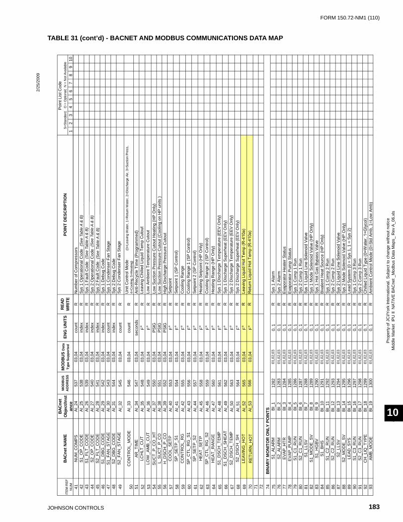
FORm 150.72-nm1 (110)
183JOHnSOn COnTROLS
10
2/25
/200
9
12
34
56
78
910
POIN
T D
ESC
RIP
TIO
NIT
Em R
EF
nU
mBA
Cne
t NAM
EPo
int L
ist C
ode
S=St
anda
rd;
O =
Opt
iona
l; n
= n
ot A
vaila
ble
BAC
net
Obj
ect/I
nst
ance
MO
DB
US
AD
DR
ESS
MO
DBU
S D
ata
Type
Sup
port
ed E
NG
UN
ITS
REA
D
WR
ITE
41n
Um
_CO
mPS
AI_2
453
703
,04
coun
tR
num
ber o
f Com
pres
sors
42S1
_OP_
CO
DE
AI_2
553
803
,04
inde
xR
Sys
1 O
pera
tiona
l Cod
e (D
efin
ition
in T
able
32)
43S1
_FLT
_CO
DE
AI_2
653
903
,04
inde
xR
Sys
1 Fa
ult C
ode
(Def
initi
on in
Tab
le 3
2)44
S2_O
P_C
OD
EAI
_27
540
03,0
4in
dex
RSy
s 2
Ope
ratio
nal C
ode
(Def
initi
on in
Tab
le 3
2)45
S2_F
LT_C
OD
EAI
_28
541
03,0
4in
dex
RSy
s 2
Faul
t Cod
e (D
efin
ition
in T
able
32)
46S1
_DBG
_CO
DE
AI_2
954
203
,04
inde
xR
Sys
1 D
ebug
Cod
e47
S1_F
An_S
TAG
EAI
_30
543
03,0
4co
unt
RSy
s 1
Con
dens
er F
an S
tage
48S2
_DBG
_CO
DE
AI_3
154
403
,04
inde
xR
Sys
2 D
ebug
Cod
e49
S2_F
An_S
TAG
EAI
_32
545
03,0
4co
unt
RSy
s 2
Con
dens
er F
an S
tage
50C
On
TRO
L_m
OD
EAI
_33
546
03,0
4co
unt
RU
nit C
ontro
l mod
e
(0
=Lea
ving
Wat
er, 1
=Ret
urn
Wat
er, 2
=Dis
char
ge A
ir, 3
=Suc
tion
Pres
s,
4=C
oolin
g, 5
=Hea
ting)
51AR
_TIm
EAI
_34
547
03,0
4se
cond
sR
Anti-
Rec
ycle
Tim
e (P
rogr
amm
ed)
52LC
HLT
_CU
TAI
_35
548
03,0
4F °
RLe
avin
g C
hille
d Li
quid
Tem
p C
utou
t53
LOW
_Am
B_C
UT
AI_3
654
903
,04
F °R
Low
Am
bien
t Tem
pera
ture
Cut
out
54SU
CT_
P_C
O_H
TAI
_37
550
03,0
4PS
IGR
Low
Suc
tion
Pres
sure
Cut
out H
eatin
g (H
P O
nly)
55L_
SUC
T_P_
CO
AI_3
855
103
,04
PSIG
RLo
w S
uctio
n Pr
essu
re C
utou
t (C
oolin
g on
HP
units
)56
H_D
SCH
_P_C
OAI
_39
552
03,0
4PS
IGR
Hig
h D
isch
arge
Pre
ssur
e C
utou
t57
CO
OL_
SETP
AI_4
055
303
,04
F °R
Setp
oint
58
SP_S
ETP_
S1AI
_41
554
03,0
4F °
RSe
tpoi
nt 1
(SP
Con
trol)
59C
On
TRO
L_R
GAI
_42
555
03,0
4F °
RC
oolin
g R
ange
60SP
_CTL
_RG
_S1
AI_4
355
603
,04
F °R
Coo
ling
Ran
ge 1
(SP
Con
trol)
61SP
_SET
P_S2
AI_4
455
703
,04
F°R
Setp
oint
2 (S
P C
ontro
l)62
HEA
T_SE
TPAI
_45
558
03,0
4F °
RH
eatin
g Se
tpoi
nt (H
P O
nly)
63SP
_CTL
_RG
_S2
AI_4
655
903
,04
F °R
Coo
ling
Ran
ge 2
(SP
Con
trol)
64H
EAT_
RAn
GE
AI_4
756
003
,04
F °R
Hea
ting
Ran
ge (H
P O
nly)
65S1
_DSC
H_T
EmP
AI_4
856
103
,04
F °R
Sys
1 D
isch
arge
Tem
pera
ture
(EEv
Onl
y)66
S1_D
SCH
_SH
EAT
AI_4
956
203
,04
F °R
Sys
1 D
isch
arge
Sup
erhe
at (E
Ev O
nly)
67S2
_DSC
H_T
EmP
AI_5
056
303
,04
F °R
Sys
2 D
isch
arge
Tem
pera
ture
(EEv
Onl
y)68
S2_D
SCH
_SH
AI_5
156
403
,04
F °R
Sys
2 D
isch
arge
Sup
erhe
at (E
Ev O
nly)
69LE
AvIn
G_H
OT
AI_5
256
503
,04
F°R
Leav
ing
Liqu
id H
ot T
emp
(R-4
10a)
70R
ETU
Rn
_HO
TAI
_53
566
03,0
4F°
RR
etur
n Li
quid
Hot
Tem
p (R
-410
a)71 72 74 75
S1_A
LAR
mBI
_112
8201
,02,
030,
1R
Sys
1 Al
arm
76S2
_ALA
Rm
BI_2
1283
01,0
2,03
0, 1
RSy
s 2
Alar
m77
EvAP
_HTR
BI_3
1284
01,0
2,03
0, 1
REv
apor
ator
Hea
ter S
tatu
s78
EvAP
_PU
mP
BI_4
1285
01,0
2,03
0, 1
REv
apor
ator
Pum
p St
atus
79S1
_C1_
RU
nBI
_512
8601
,02,
030,
1R
Sys
1 C
omp
1 R
un80
S2_C
1_R
Un
BI_6
1287
01,0
2,03
0, 1
RSy
s 2
Com
p 1
Run
81S1
_LLS
vBI
_712
8801
,02,
030,
1R
Sys
1 Li
quid
Lin
e So
leno
id V
alve
82S1
_mO
DE_
SvBI
_812
8901
,02,
030,
1R
Sys
1 m
ode
Sole
noid
val
ve (H
P O
nly)
83S1
_HG
BvBI
_912
9001
,02,
030,
1R
Sys
1 H
ot G
as B
ypas
s va
lve
84S1
_BH
SBI
_10
1291
01,0
2,03
0, 1
RBi
vale
nt H
eat S
ourc
e (H
P O
nly)
85S1
_C2_
RU
nBI
_11
1292
01,0
2,03
0, 1
RSy
s 1
Com
p 2
Run
86S2
_C2_
RU
nBI
_12
1293
01,0
2,03
0, 1
RSy
s 2
Com
p 2
Run
87S2
_LLS
vBI
_13
1294
01,0
2,03
0, 1
RSy
s 2
Liqu
id L
ine
Sole
noid
Val
ve88
S2_m
OD
E_Sv
BI_1
412
9501
,02,
030,
1R
Sys
2 m
ode
Sole
noid
val
ve (H
P O
nly)
89LE
AD_S
YSBI
_15
1296
01,0
2,03
0, 1
RLe
ad S
yste
m (0
= S
ys 1
, 1 =
Sys
2)
90S1
_C3_
RU
nBI
_16
1297
01,0
2,03
0, 1
RSy
s 1
Com
p 3
Run
91S2
_C3_
RU
nBI
_17
1298
01,0
2,03
0, 1
RSy
s 2
Com
p 3
Run
92C
H_L
Iq_T
YPE
BI_1
812
9901
,02,
030,
1R
Chi
lled
Liqu
id T
ype
(0=W
ater
, 1=G
lyco
l)93
AmB_
mO
DE
BI_1
913
0001
,02,
030,
1R
Ambi
ent C
ontro
l mod
e (0
=Std
Am
b, 1
=Low
Am
b)
BI
NAR
Y M
ON
ITO
R O
NLY
PO
INTS
Mid
Mar
ket N
ativ
e Ba
cnet
_Mod
bus
Prop
erty
of J
CI/Y
ork
Inte
rnat
iona
l. Su
bjec
t to
chan
ge w
ithou
t not
ice
mid
dle
mar
ket
IPU
II n
ATIv
E BA
Cne
t _m
odbu
s D
ata
map
s_ R
ev A
_06.
xls
Page
2 o
f 3
(See
Tab
le A
& B
)(S
ee T
able
A &
B)
(See
Tab
le A
& B
)(S
ee T
able
A &
B)
TABLE 31 (cont’d) - BACNET AND MODBUS COMMUNICATIONS DATA MAP

JOHnSOn COnTROLS184
FORm 150.72-nm1 (110)Maintenance
2/25
/200
9
12
34
56
78
910
POIN
T D
ESC
RIP
TIO
NIT
Em R
EF
nU
mBA
Cne
t NAM
EPo
int L
ist C
ode
S=St
anda
rd;
O =
Opt
iona
l; n
= n
ot A
vaila
ble
BAC
net
Obj
ect/I
nst
ance
MO
DB
US
AD
DR
ESS
MO
DBU
S D
ata
Type
Sup
port
ed E
NG
UN
ITS
REA
D
WR
ITE
94C
nTL
_mO
DE
BI_2
013
0101
,02,
030,
1R
Loca
l/Rem
ote
Con
trol m
ode
(0=L
ocal
, 1=R
emot
e)95
DAT
A_U
nIT
BI_2
113
0201
,02,
030,
1R
Uni
ts (0
=Im
peria
l, 1=
SI)
96AU
TO_L
LBI
_22
1303
01,0
2,03
0, 1
RLe
ad/L
ag C
ontro
l mod
e (0
=man
ual,
1=Au
to)
Cod
eO
pera
tiona
l Cod
esC
ode
0n
o Ab
norm
al C
ondi
tion
01
Uni
t Sw
itch
Off
12
Syst
em S
witc
h O
ff2
3Lo
ck-O
ut3
4U
nit F
ault
45
Syst
em F
ault
56
Rem
ote
Shut
dow
n6
7D
aily
Sch
edul
e Sh
utdo
wn
78
no
Run
Per
mis
sive
8`
9n
o C
ool L
oad
910
Anti-
Coi
ncid
ence
Tim
er A
ctiv
e10
11An
ti-R
ecyc
le T
imer
Act
ive
1112
man
ual O
verr
ide
1213
Suct
ion
Lim
iting
13
14D
isch
arge
Lim
iting
1415
1516
Load
Lim
iting
1617
Com
pres
sor(
s) R
unni
ng17
1818
1919
2020
2121
2222
2323
2424
2525
2626
2727
2828
2929
3030
1 2 3 4 5 6 7 8 9 10
NO
TES
See
the
appl
icab
le m
iddl
e m
arke
t Chi
ller O
pera
tions
man
ual
for m
ore
deta
ils
NO
TE:
N
ote
that
thes
e ta
bles
of F
AULT
and
OPE
RAT
ION
AL C
odes
are
for a
ll D
X pr
oduc
ts.
Faul
t Cod
es
mP/
HPC
O In
hibi
t
The
YCW
L us
es th
e sa
me
firm
war
e as
a Y
CAL
, it
just
igno
res
Fan
Con
trol
The
IPU
II b
ased
YC
AL /Y
CU
L U
nits
are
con
figur
ed fo
r nat
ive
BAC
net m
S/TP
and
mod
bus
RTU
com
mun
icat
ions
. Th
e m
icro
gate
way
pro
duct
is n
ot re
quire
d fo
r the
se 2
inte
rface
s
BAC
net O
bjec
t Typ
es:
0=
Anal
og In
, 1 =
Ana
log
Out
, 2=
Anal
og v
alue
, 3=
Bin
ary
In,
4 =
Bina
ry O
utpu
t, 5
= B
inar
y va
lue,
8=
Dev
ice,
15
= Al
arm
not
ifica
tion
( 0
-127
are
rese
rved
ASH
RAE
Obj
ects
)W
C=
Inch
es o
f wat
er c
olum
n;
CFM
= C
ubic
Fee
r per
Min
ute;
FPM
= F
eet p
er M
inut
e: P
SI =
Lbs
per
squ
are
inch
; Pa
= P
asca
ls;
kPa
= K
ilopa
scal
s; P
Pm =
Par
t Per
mill
ion;
kJ
/kg
= Ki
lojo
ules
per
Kilo
gram
Uni
t mot
or C
urre
ntLo
w S
uper
heat
Sens
or F
ault
mP/
HPC
O F
ault
Low
Eva
pora
tor T
empe
ratu
reIn
corr
ect R
efrig
eran
t Pro
gram
med
Pow
er F
ailu
re, M
anua
l Res
et R
equi
red
Low
mot
or C
urre
nt /
mP
/ HPC
Om
otor
Cur
rent
Unb
alan
ced
Low
Diff
eren
tial O
il Pr
essu
reG
roun
d Fa
ult
TABL
E A
TABL
E B
Hig
h D
isch
arge
Tem
pera
ture
Impr
oper
Pha
se R
otat
ion
Hig
h m
otor
Cur
rent
LLSv
not
On
Low
Bat
tery
War
ning
Hig
h O
il Te
mpe
ratu
re
Low
Lea
ving
Chi
lled
Liqu
id T
emp
Hig
h D
isch
arge
Pre
ssur
eH
igh
Diff
eren
tial O
il Pr
essu
reLo
w S
uctio
n Pr
essu
re
no
Faul
tvA
C U
nder
vol
tage
Low
Am
bien
t Tem
pera
ture
Hig
h Am
bien
t Tem
pera
ture
Mid
Mar
ket N
ativ
e Ba
cnet
_Mod
bus
Prop
erty
of J
CI/Y
ork
Inte
rnat
iona
l. Su
bjec
t to
chan
ge w
ithou
t not
ice
mid
dle
mar
ket
IPU
II n
ATIv
E BA
Cne
t _m
odbu
s D
ata
map
s_ R
ev A
_06.
xls
Page
3 o
f 3
TABLE 31 (cont’d) - BACNET AND MODBUS COMMUNICATIONS DATA MAP
FORm 150.72-nm1 (110)
185JOHnSOn COnTROLS
10
Yorktalk 2 Communications
Received Data (Control Data)
The unit receives eight data values from the MicroGateway or E-Link. The first four are analog values and the last four are digital values. These eight data values are used as control parameters when in REMOTE mode. When the unit is in LOCAL mode, these eight values are ignored. If the unit receives no valid YorkTalk 2 transmission for 5 minutes it will revert back to all local control values. Table 32 “Yorktalk 2 Communications Data Map” lists the control parameters. These values are found under feature 54 in the MicroGateway or E-Link.
Transmitted Data
After receiving a valid transmission from the MicroGateway or E-Link, the unit will transmit either operational data or history buffer data depending on the “History Buffer Request” on ENG PAGE 10. Data must be transmitted for every page under feature 54. If there is no value to be sent to a particular page, a zero will be sent. Table 32 “Yorktalk 2 Communications Data Map” shows the data values and page listings for this unit.
The latest point map information is listed on the Johnson Controls Equip-ment Integration website.
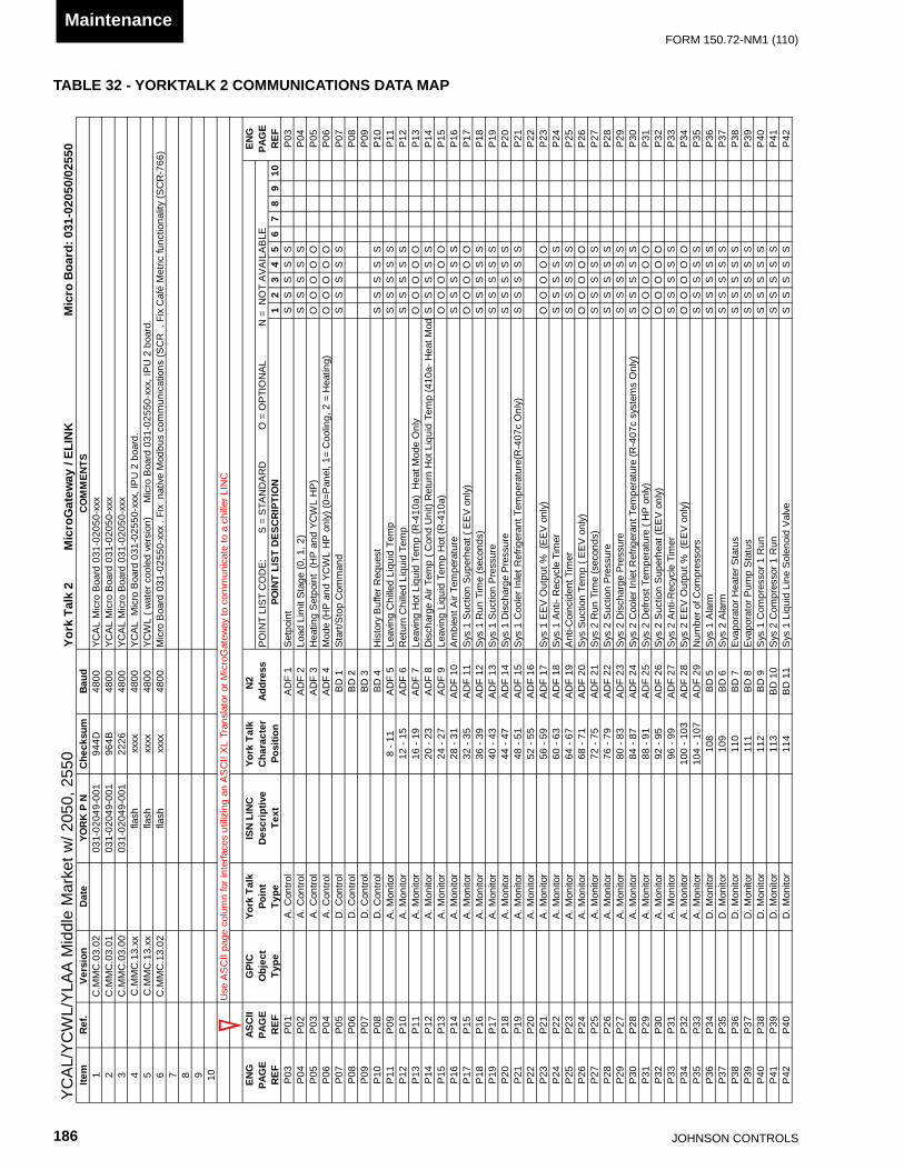
JOHnSOn COnTROLS186
FORm 150.72-nm1 (110)Maintenance
TABLE 32 - YORKTALK 2 COMMUNICATIONS DATA MAPYo
rk T
alk
2
Mic
roG
atew
ay /
ELIN
KM
icro
Boa
rd: 0
31-0
2050
/025
50ST
NEM
MO
CduaB
muskcehC
N P K
ROY
etaD
noisreV.fe
RmetI
1C
.MM
C.0
3.02
031-
0204
9-00
194
4D48
002
C.M
MC
.03.
0103
1-02
049-
001
964B
4800
3C
.MM
C.0
3.00
031-
0204
9-00
122
2648
00xxxx
hsalfxx.31.
CM
M.C
448
00xxxx
hsalfxx.31.
CM
M.C
548
00xxxx
hsalf20.31.
CM
M.C
648
007 8 9 10
Use
AS
CII
page
col
umn
for i
nter
face
s ut
ilizin
g an
AS
CII
XL
Tran
slat
or o
r Mic
roG
atew
ay to
com
mun
icat
e to
a c
hille
r LIN
C
ENG
ASC
IIG
PIC
York
Tal
kIS
N L
INC
York
Tal
kN
2 EN
GPA
GE
PAG
EO
bjec
tPo
int
Des
crip
tive
Cha
ract
erAd
dres
sP
OIN
T LI
ST
CO
DE
:
S
= S
TAN
DA
RD
O
= O
PTI
ON
AL
N
= N
OT
AV
AIL
AB
LEPA
GE FE
R01
98
76
54
32
1N
OITPIR
CSED TSIL T
NIOP
noitisoPtxeT
epyTepyT
FER
FER
30P
SS
SS
Stniopte
S1 F
DA
lortnoC .
A10
P30
P40
PS
SS
SS
)2 ,1 ,0( egatS ti
miL daoL2 F
DA
lortnoC .
A20
P40
P50
PO
OO
OO
)P
H LW
CY dna P
H( tniopteS gnitae
H3 F
DA
lortnoC .
A30
P50
P60
PO
OO
OO
)gnitaeH = 2 ,gniloo
C =1 ,lenaP=0( )ylno
PH L
WCY dna
PH( edo
M4 F
DA
lortnoC .
A40
P60
P70
PS
SS
SS
dnam
moC pot
S/tratS
1 D
Blortno
C .D
50P
70P
2 D
Blortno
C .D
60P
80P
P0 8
3 D
Blortno
C .D
70P
90P
P09 01
PS
SS
SS
tseuqeR reffu
B yrotsiH
4 D
Blortno
C .D
80P
01P
pmeT diuqiL dellih
C gnivaeL5 F
DA
11 - 8rotino
M .A
90P
11P
SS
SS
SP
11p
meT diuqiL dellihC nrute
R6 F
DA
51 - 21rotino
M .A
01P
21P
SS
SS
SP
12yln
O edoM tae
H )a014-R( p
meT diuqiL toH gnivaeL
7 FD
A91 - 61
rotinoM .
A11
P31
PO
OO
OO
P13 41
PS
SS
SS
doM tae
H -a014( pmeT diuqiL to
H nruteR )tin
U dnoC ( p
meT riA egrahcsi
D8 F
DA
32 - 02rotino
M .A
21P
41P
)a014-R( to
H pmeT diuqiL gnivaeL
9 FD
A72 - 42
rotinoM .
A31
P51
PO
OO
OO
P15 61
PS
SS
SS
erutarepmeT ri
A tneibm
A01 F
DA
13 - 82rotino
M .A
41P
61P
)ylno V
EE ( taehrepu
S noitcuS 1 sy
S11 F
DA
53 - 23rotino
M .A
51P
71P
OO
OO
OP
17 81P
SS
SS
S)sdnoces( e
miT nuR 1 sy
S21 F
DA
93 - 63rotino
M .A
61P
81P
91P
SS
SS
Serusser
P noitcuS 1 sy
S31 F
DA
34 - 04rotino
M .A
71P
91P
02P
SS
SS
Serusser
P egrahcsiD 1 sy
S41 F
DA
74 - 44rotino
M .A
81P
02P
12P
SS
SS
S)yln
O c704-R(erutarep
meT tnaregirfeR telnI reloo
C 1 syS
51 FD
A15 - 84
rotinoM .
A91
P12
P61 F
DA
55 - 25rotino
M .A
02P
22P
P2 2
)ylno V
EE(
% tuptuO
VE
E 1 syS
71 FD
A95 - 65
rotinoM .
A12
P32
PO
OO
OO
P23 42
PS
SS
SS
remiT elcyce
R -itnA 1 sy
S81 F
DA
36 - 06rotino
M .A
22P
42P
52P
SS
SS
Sre
miT tnedicnioC-itn
A91 F
DA
76 - 46rotino
M .A
32P
52P
)ylno V
EE ( p
meT noitcuS sy
S02 F
DA
17 - 86rotino
M .A
42P
62P
OO
OO
OP
26 72P
SS
SS
S)sdnoces( e
miT nuR 2 sy
S12 F
DA
57 - 27rotino
M .A
52P
72P
82P
SS
SS
Serusser
P noitcuS 2 sy
S22 F
DA
97 - 67rotino
M .A
62P
82P
92P
SS
SS
Serusser
P egrahcsiD 2 sy
S32 F
DA
38 - 08rotino
M .A
72P
92P
03P
SS
SS
S)yln
O smetsys c704-
R( erutarepmeT tnaregirfe
R telnI relooC 2 sy
S42 F
DA
78 - 48rotino
M .A
82P
03P
13P
OO
OO
O )ylno
PH ( erutarep
meT tsorfeD 2 sy
S52 F
DA
19 - 88rotino
M .A
92P
13P
)ylno V
EE( taehrepu
S noitcuS 2 sy
S62 F
DA
59 - 29rotino
M .A
03P
23P
OO
OO
OP
32 33P
SS
SS
Sre
miT elcyceR-itn
A 2 syS
72 FD
A99 - 69
rotinoM .
A13
P33
P )ylno
VE
E( % tuptu
O V
EE 2 sy
S82 F
DA
301 - 001rotino
M .A
23P
43P
OO
OO
OP
34 53P
SS
SS
Ssrosserp
moC fo reb
muN
92 FD
A701 - 401
rotinoM .
A33
P53
P63
PS
SS
SS
mralA 1 sy
S5
DB
801rotino
M .D
43P
63P
73P
SS
SS
Smral
A 2 syS
6 D
B901
rotinoM .
D53
P73
P83
PS
SS
SS
sutatS retae
H rotaropavE
7 D
B011
rotinoM .
D63
P83
P93
PS
SS
SS
sutatS p
muP rotaropav
E8
DB
111rotino
M .D
73P
93P
04P
SS
SS
Snu
R 1 rosserpmo
C 1 syS
9 D
B211
rotinoM .
D83
P04
P14
PS
SS
SS
nuR 1 rosserp
moC 2 sy
S01
DB
311rotino
M .D
93P
14P
24P
SS
SS
Sevla
V dioneloS eniL diuqiL 1 sy
S11
DB
411rotino
M .D
04P
24P
YCA
L M
icro
Boa
rd 0
31-0
2050
-xxx
Mic
ro B
oard
031
-025
50-x
xx .
Fix
nat
ive
Mod
bus
com
mun
icat
ions
(SC
R .
Fix
Caf
é M
etric
func
tiona
lity
(SC
R-7
66)
YC
AL/
YC
WL/
YLA
A M
iddl
e M
arke
t w/ 2
050,
255
0
YCA
L M
icro
Boa
rd 0
31-0
2550
-xxx
, IP
U 2
boa
rd.
YCW
L ( w
ater
coo
led
vers
ion)
M
icro
Boa
rd 0
31-0
2550
-xxx
, IP
U 2
boa
rd.
YCA
L M
icro
Boa
rd 0
31-0
2050
-xxx
YCA
L M
icro
Boa
rd 0
31-0
2050
-xxx

FORm 150.72-nm1 (110)
187JOHnSOn COnTROLS
10
ENG
ASC
IIG
PIC
York
Tal
kIS
N L
INC
York
Tal
kN
2 EN
GPA
GE
PAG
EO
bjec
tPo
int
Des
crip
tive
Cha
ract
erAd
dres
sP
OIN
T LI
ST
CO
DE
:
S
= S
TAN
DA
RD
O
= O
PTI
ON
AL
N
= N
OT
AV
AIL
AB
LEPA
GE FE
R01
98
76
54
32
1N
OITPIR
CSED TSIL T
NIOP
noitisoPtxeT
epyTepyT
FER
FER
34P
SS
SS
Sevla
V ssapyB sa
G toH 1 sy
S21
DB
511rotino
M .D
14P
34P
44P
SS
SS
Snu
R 2 rosserpmo
C 1 syS
31 D
B611
rotinoM .
D24
P44
P54
PS
SS
SS
nuR 2 rosserp
moC 2 sy
S41
DB
711rotino
M .D
34P
54P
64P
SS
SS
Sevla
V dioneloS eniL diuqiL 2 sy
S51
DB
811rotino
M .D
44P
64P
74P
SS
SS
S)2 sy
S = 1 ,1 syS = 0(
metsyS daeL
61 D
B911
rotinoM .
D54
P74
P84
PS
SS
SS
nuR 3 rosserp
moC 1 sy
S71
DB
021rotino
M .D
64P
84P
94P
SS
SS
Snu
R 3 rosserpmo
C 2 syS
81 D
B121
rotinoM .
D74
P94
P)locyl
G=1 ,retaW=0( epyT diuqiL dellih
C91
DB
221rotino
M .D
84P
05P
SS
SS
SP
50 15P
NS
SS
S)b
mA
woL=1 ,bm
A dtS=0( edo
M lortnoC tneib
mA
02 D
B321
rotinoM .
D94
P15
P25
PS
SS
SS
)etome
R=1 ,lacoL=0( edoM lortno
C etome
R/lacoL12
DB
421rotino
M .D
05P
25P
35P
SS
SS
S)I
S=1 ,lairepmI=0( stin
U22
DB
521rotino
M .D
15P
35P
45P
SS
SS
S)otu
A=1 ,launaM=0( edo
M lortnoC gaL/daeL
32 D
B621
rotinoM .
D25
P45
P55
PS
SS
SS
evlaV ssapy
B saG to
H 2 syS
42 D
B721
rotinoM .
D35
P55
P65
PS
SS
SS
edoC lanoitarep
O 1 syS*
1 ID
A821
rotinoM edo
C45
P65
P75
PS
SS
SS
edoC tluaF 1 sy
S*2 I
DA
921rotino
M edoC
55P
75P
85P
SS
SS
Sedo
C lanoitarepO 2 sy
S*3 I
DA
031rotino
M edoC
65P
85P
95P
SS
SS
Sedo
C tluaF 2 syS*
4 ID
A131
rotinoM edo
C75
P95
P5 I
DA
231rotino
M edoC
85P
06P
SS
SS
SP
60 16P
SS
SS
Segat
S naF resnednoC 1 sy
S6 I
DA
331rotino
M edoC
95P
16P
7 ID
A431
rotinoM edo
C06
P26
PS
SS
SS
P62 36
PS
SS
SS
egatS naF resnedno
C 2 syS
8 ID
A531
rotinoM edo
C16
P36
P9 I
DA
631rotino
M edoC
26P
46P
P64
taeH=5 ,loo
C=4 ,P
S=3 ,riA si
D=2 ,rtW te
R=1 ,rtW vL=0( edo
M lortnoC tin
U01 I
DA
731rotino
M edoC
36P
56P
)SS
SS
SP
65 66P
SS
SS
S)de
mmargor
P( emiT elcyce
R-itnA
03 FD
A141 - 831
rotinoM .
A46
P66
Ptuotu
C pmeT diuqiL dellih
C gnivaeL13 F
DA
541 - 241rotino
M .A
56P
76P
SS
SS
SP
67 86P
SS
SS
Stuotu
C erutarepmeT tneib
mA
woL23 F
DA
941 - 641rotino
M .A
66P
86P
96P
SS
SS
S)yln
O P
H gnitaeH( tuotu
C erusserP noitcu
S woL
33 FD
A351 - 051
rotinoM .
A76
P96
P07
PS
SS
SS
)ylno P
H gnilooC( tuotu
C erusserP noitcu
S woL
43 FD
A751 - 451
rotinoM .
A86
P07
P17
PS
SS
SS
tuotuC erusser
P egrahcsiD hgi
H53 F
DA
161 - 851rotino
M .A
96P
17P
27P
SS
SS
S)lacol( tniopte
S63 F
DA
561 - 261rotino
M .A
07P
27P
37P
SS
SS
Segna
R gnilooC
73 FD
A961 - 661
rotinoM .
A17
P37
P47
PO
OO
OO
)ylno P
H LW
CY dna P
H ( tniopteS gnitae
H ,)lortnoC
PS ( 2 tniopte
S83 F
DA
371 - 071rotino
M .A
27P
47P
57P
OO
OO
O)ylno
PH L
WCY dna
PH( egna
R taeH ,)lortno
C P
S( 2 tniopteS egna
R looC
93 FD
A771 - 471
rotinoM .
A37
P57
P)ylno
VE
E( pmeT egrahcsi
D 1 syS
04 FD
A181 - 871
rotinoM .
A47
P67
PO
OO
OO
P76
)ylno V
EE( taehrepu
S egrahcsiD 1 sy
S14 F
DA
581 - 281rotino
M .A
57P
77P
OO
OO
OP
77)ylno
VE
E( pmeT egrahcsi
D 2 syS
24 FD
A981 - 681
rotinoM .
A67
P87
PO
OO
OO
P78
)ylno V
EE( taehrepu
S egrahcsiD 2 sy
S34 F
DA
391 - 091rotino
M .A
77P
97P
OO
OO
OP
7952
DB
491rotino
M .D
87P
08P
P80
62 D
B591
rotinoM .
D97
P18
PP
8172
DB
691rotino
M .D
08P
28P
P82
82 D
B791
rotinoM .
D18
P38
PP
8392
DB
891rotino
M .D
28P
48P
P84
NO
TE: T
he A
ppro
pria
te P
rodu
ct C
ode
List
ing
Sum
mar
y S
houl
d A
ccom
pany
Doc
umen
t
TABLE 32 (cont’d) - YORKTALK 2 COMMUNICATIONS DATA MAP

JOHnSOn COnTROLS188
FORm 150.72-nm1 (110)Maintenance
edoC tluaF
IICSA
GNE
edoC lanoitarep
OII
CSAG
NEE
GAPE
GAPE
GAPE
GAPE
DO
C.TLUAF_
C55P
75PE
DO
C.REP
O_C
45P65P
edoC tluaF o
N0
0noitidno
C lamronb
A oN
00
a/n1
1ff
O hctiw
S tinU
11
erutarepmeT tneib
mA
woL2
2ff
O hctiw
S metsy
S2
2a/n
33
tuO-kcoL
33
erutarepmeT diuqiL dellih
C gnivaeL woL
44
tluaF tinU
44
erusserP egrahcsi
D hgiH
55
tluaF metsy
S5
5a/n
66
nwodtuh
S etome
R6
6erusser
P noitcuS
woL7
7n
wodtuhS eludehc
S yliaD
77
a/n8
8evissi
mreP nu
R oN
88
a/n9
9daoL loo
C oN
99
a/n01
01evitc
A remiT ecnedicnio
C-itnA
0101
a/n11
11evitc
A remiT elcyce
R-itnA
1111
a/n21
21edirrev
O launaM
2121
a/n31
31gniti
miL noitcuS
3131
a/n41
41gniti
miL egrahcsiD
4141
a/n51
51a/n
5151
a/n61
61gniti
miL daoL61
61a/n
7171
gninnuR )s(rosserp
moC
7171 18
18H
eat P
ump
Load
Lim
iting
( H
P O
nly)
18
18M
P /
HP
CO
Fau
lt19
19Lo
w E
vapo
rato
r Tem
pera
ture
2020
n/a
2121
n/a
2222
Uni
t Mot
or C
urre
nt23
23Lo
w S
uper
heat
2424
Sen
sor F
ault
2525
Dis
char
ge In
hibi
t26
26M
P/H
PC
O In
hibi
t27
27P
ump
Trip
2828
Pum
p Fa
il M
ake
Flow
TABLE 32 (cont’d) - YORKTALK 2 COMMUNICATIONS DATA MAP
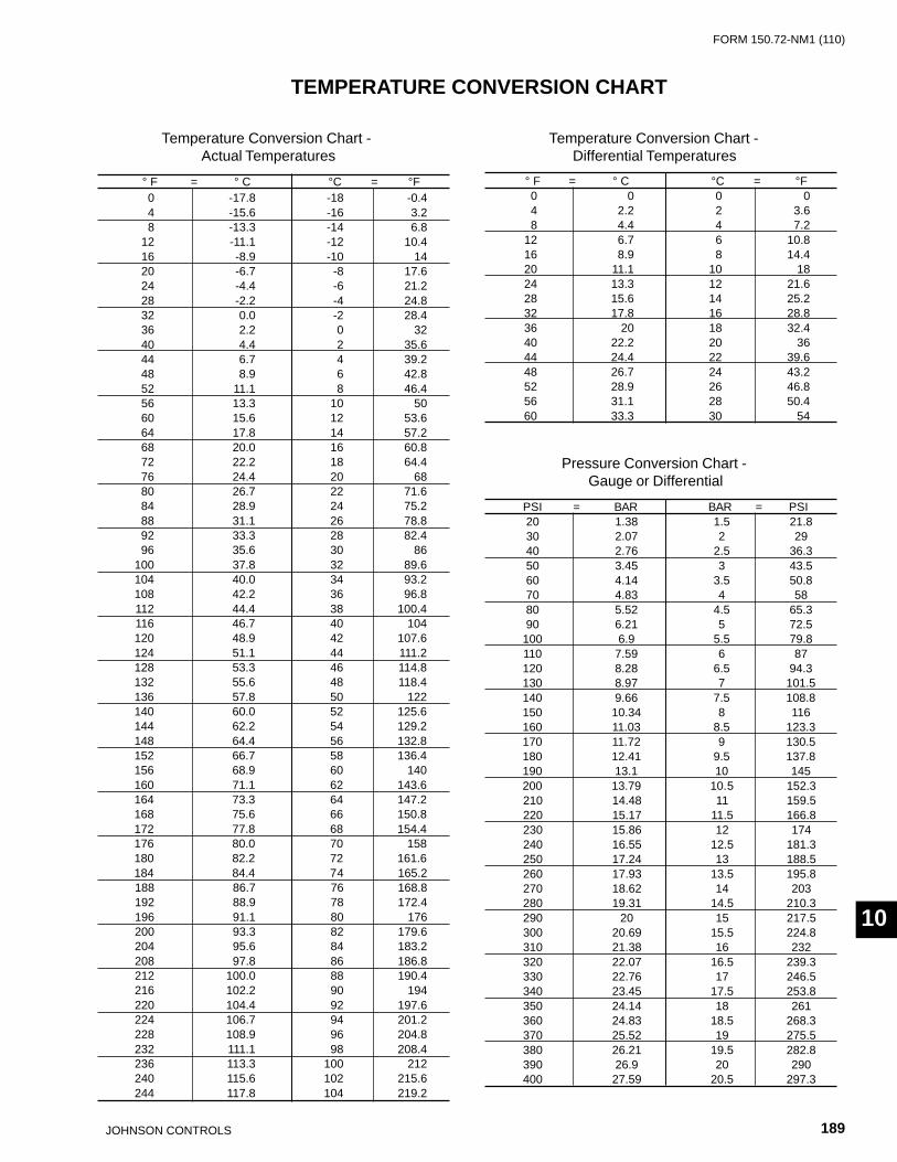
FORm 150.72-nm1 (110)
189JOHnSOn COnTROLS
10
TEMPERATURE CONVERSION CHART
Temperature Conversion Chart -Actual Temperatures
TEMPERATURE CONVERSION CHART
Temperature Conversion Chart -Differential Temperatures
Pressure Conversion Chart -Gauge or Differential
° F = ° C °C = °F0 -17.8 -18 -0.44 -15.6 -16 3.28 -13.3 -14 6.8
12 -11.1 -12 10.416 -8.9 -10 1420 -6.7 -8 17.624 -4.4 -6 21.228 -2.2 -4 24.832 0.0 -2 28.436 2.2 0 3240 4.4 2 35.644 6.7 4 39.248 8.9 6 42.852 11.1 8 46.456 13.3 10 5060 15.6 12 53.664 17.8 14 57.268 20.0 16 60.872 22.2 18 64.476 24.4 20 6880 26.7 22 71.684 28.9 24 75.288 31.1 26 78.892 33.3 28 82.496 35.6 30 86
100 37.8 32 89.6104 40.0 34 93.2108 42.2 36 96.8112 44.4 38 100.4116 46.7 40 104120 48.9 42 107.6124 51.1 44 111.2128 53.3 46 114.8132 55.6 48 118.4136 57.8 50 122140 60.0 52 125.6144 62.2 54 129.2148 64.4 56 132.8152 66.7 58 136.4156 68.9 60 140160 71.1 62 143.6164 73.3 64 147.2168 75.6 66 150.8172 77.8 68 154.4176 80.0 70 158180 82.2 72 161.6184 84.4 74 165.2188 86.7 76 168.8192 88.9 78 172.4196 91.1 80 176200 93.3 82 179.6204 95.6 84 183.2208 97.8 86 186.8212 100.0 88 190.4216 102.2 90 194220 104.4 92 197.6224 106.7 94 201.2228 108.9 96 204.8232 111.1 98 208.4236 113.3 100 212240 115.6 102 215.6244 117.8 104 219.2
° F = ° C °C = °F0 0 0 04 2.2 2 3.68 4.4 4 7.2
12 6.7 6 10.816 8.9 8 14.420 11.1 10 1824 13.3 12 21.628 15.6 14 25.232 17.8 16 28.836 20 18 32.440 22.2 20 3644 24.4 22 39.648 26.7 24 43.252 28.9 26 46.856 31.1 28 50.460 33.3 30 54
PSI = BAR BAR = PSI20 1.38 1.5 21.830 2.07 2 2940 2.76 2.5 36.350 3.45 3 43.560 4.14 3.5 50.870 4.83 4 5880 5.52 4.5 65.390 6.21 5 72.5
100 6.9 5.5 79.8110 7.59 6 87120 8.28 6.5 94.3130 8.97 7 101.5140 9.66 7.5 108.8150 10.34 8 116160 11.03 8.5 123.3170 11.72 9 130.5180 12.41 9.5 137.8190 13.1 10 145200 13.79 10.5 152.3210 14.48 11 159.5220 15.17 11.5 166.8230 15.86 12 174240 16.55 12.5 181.3250 17.24 13 188.5260 17.93 13.5 195.8270 18.62 14 203280 19.31 14.5 210.3290 20 15 217.5300 20.69 15.5 224.8310 21.38 16 232320 22.07 16.5 239.3330 22.76 17 246.5340 23.45 17.5 253.8350 24.14 18 261360 24.83 18.5 268.3370 25.52 19 275.5380 26.21 19.5 282.8390 26.9 20 290400 27.59 20.5 297.3
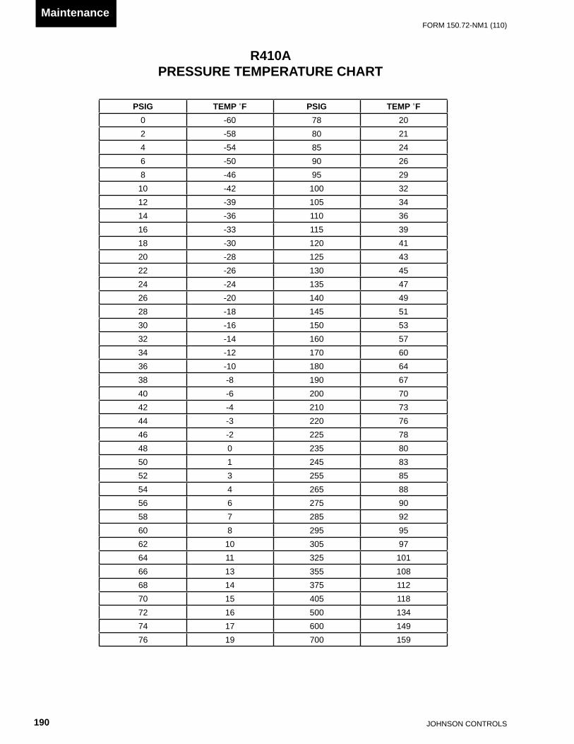
JOHnSOn COnTROLS190
FORm 150.72-nm1 (110)Maintenance
PSIG TEMP ˚F PSIG TEMP ˚F0 -60 78 202 -58 80 214 -54 85 246 -50 90 268 -46 95 29
10 -42 100 3212 -39 105 3414 -36 110 3616 -33 115 3918 -30 120 4120 -28 125 4322 -26 130 4524 -24 135 4726 -20 140 4928 -18 145 5130 -16 150 5332 -14 160 5734 -12 170 6036 -10 180 6438 -8 190 6740 -6 200 7042 -4 210 7344 -3 220 7646 -2 225 7848 0 235 8050 1 245 8352 3 255 8554 4 265 8856 6 275 9058 7 285 9260 8 295 9562 10 305 9764 11 325 10166 13 355 10868 14 375 11270 15 405 11872 16 500 13474 17 600 14976 19 700 159
R410A PRESSURE TEMPERATURE CHART

FORm 150.72-nm1 (110)
191JOHnSOn COnTROLS
10
NOTES

©2010 Johnson Controls, Inc. P.O. Box 423, milwaukee, WI 53203www.johnsoncontrols.com
Printed in USA 150.72-nm1 (110)Replaces 150.72-nm1 (908)

CHILLERMODEL VOLT HZ
MINIMUM CIRCUIT
AMPS
MIN N/F DISC SW
MIN DUAL ELEM FUSE
& MIN CB
MAX DUAL ELEM FUSE
& MAX CB
SYSTEM # 1COMPR 1 COMPR 2 COMPR 3 COND FANS
RLA LRA RLA LRA RLA LRA QTY FLA LRA
YLAA0091 HE
208 60 404 600 450 500 109.6 599 55.8 425 3 7.6 30.9230 60 403 600 450 500 109.6 599 55.8 425 3 7.4 37.0380 60 255 400 300 300 69.2 358 36.0 239 3 4.5 22.3460 60 200 250 225 250 54.5 310 26.9 187 3 4.0 19.0575 60 176 200 200 225 49.4 239 23.7 148 3 2.9 14.6
YLAA0101HE
208 60 460 600 500 500 55.8 425 55.8 425 55.8 425 2 7.6 30.9230 60 458 600 500 500 55.8 425 55.8 425 55.8 425 2 7.4 37.0380 60 291 400 350 350 36.0 239 36.0 239 36.0 239 2 4.5 22.3460 60 227 250 250 250 26.9 187 26.9 187 26.9 187 2 4.0 19.0575 60 200 250 225 225 23.7 148 23.7 148 23.7 148 2 2.9 14.6
YLAA0125HE
208 60 527 600 600 600 109.6 599 109.6 599 4 7.6 30.9230 60 525 600 600 600 109.6 599 109.6 599 4 7.4 37.0380 60 330 400 350 350 69.2 358 69.2 358 4 4.5 22.3460 60 264 400 300 300 54.5 310 54.5 310 4 4.0 19.0575 60 233 400 250 250 49.4 239 49.4 239 4 2.9 14.6
YLAA0141HE
208 60 582 800 700 700 109.6 599 109.6 599 109.6 599 5 7.6 30.9230 60 581 800 700 700 109.6 599 109.6 599 109.6 599 5 7.4 37.0380 60 366 600 400 400 69.2 358 69.2 358 69.2 358 5 4.5 22.3460 60 291 400 350 350 54.5 310 54.5 310 54.5 310 5 4.0 19.0575 60 257 400 300 300 49.4 239 49.4 239 49.4 239 5 2.9 14.6
YLAA0156HE
208 60 651 800 700 700 109.6 599 109.6 599 109.6 599 6 7.6 30.9230 60 649 800 700 700 109.6 599 109.6 599 109.6 599 6 7.4 37.0380 60 408 600 450 450 69.2 358 69.2 358 69.2 358 6 4.5 22.3460 60 326 400 350 350 54.5 310 54.5 310 54.5 310 6 4.0 19.0575 60 288 400 350 350 49.4 239 49.4 239 49.4 239 6 2.9 14.6
YLAA0175HE
208 60 761 1000 800 800 109.6 599 109.6 599 109.6 599 5 7.6 30.9230 60 759 1000 800 800 109.6 599 109.6 599 109.6 599 5 7.4 37.0380 60 478 600 500 500 69.2 358 69.2 358 69.2 358 5 4.5 22.3460 60 381 600 400 400 54.5 310 54.5 310 54.5 310 5 4.0 19.0575 60 338 400 400 400 49.4 239 49.4 239 49.4 239 5 2.9 14.6
Literature suppLement File with: 150.72-NM1 (908)
Form Number: 150.72-NM1 (Ls01) 409
supersedes: None
subject: YLAA0091 Corrected Electrical Data
Replace the chart on page 50 with the following chart.
eLeCtriCaL Data W/O pumps

©2009 Johnson Controls, Inc. P.O. Box 423, Milwaukee, WI 53203www.johnsoncontrols.com
Printed in UsA 150.72-NM1 (Ls01) (409)New Release
Replace the chart on page 57 with the following chart.
eLeCtriCaL Data W/ pumps (continued)CHILLERMODEL
SYSTEM # 1 SYSTEM # 2COMPR 1 COMPR 2 COMPR 3 COND FANS COMPR 1 COMPR 2 COMPR 3 COND FANS
RLA LRA RLA LRA RLA LRA QtY FLa Lra RLA LRA RLA LRA RLA LRA QtY FLa Lra
YLAA0090SE
55.8 425 55.8 425 55.8 425 2 7.6 30.9 109.6 599 55.8 425 2 7.6 30.955.8 425 55.8 425 55.8 425 2 7.4 37.0 109.6 599 55.8 425 2 7.4 37.036.0 239 36.0 239 36.0 239 2 4.5 22.3 69.2 358 36.0 239 2 4.5 22.326.9 187 26.9 187 26.9 187 2 4.0 19.0 54.5 310 26.9 187 2 4.0 19.023.7 148 23.7 148 23.7 148 2 2.9 14.6 49.4 239 23.7 148 2 2.9 14.6
YLAA0091 HE
109.6 599 55.8 425 3 7.6 30.9 109.6 599 55.8 425 3 7.6 30.9109.6 599 55.8 425 3 7.4 37.0 109.6 599 55.8 425 3 7.4 37.069.2 358 36.0 239 3 4.5 22.3 69.2 358 36.0 239 3 4.5 22.354.5 310 26.9 187 3 4.0 19.0 54.5 310 26.9 187 3 4.0 19.049.4 239 23.7 148 3 2.9 14.6 49.4 239 23.7 148 3 2.9 14.6
YLAA0091 HE
109.6 599 55.8 425 3 7.6 30.9 109.6 599 55.8 425 3 7.6 30.9109.6 599 55.8 239 3 7.4 37.0 109.6 599 55.8 425 3 7.4 37.069.2 358 36.0 187 3 4.5 22.3 69.2 358 36.0 239 3 4.5 22.354.5 310 26.9 148 3 4.0 19.0 54.5 310 26.9 187 3 4.0 19.049.4 239 23.7 425 3 2.9 14.6 49.4 239 23.7 148 3 2.9 14.6
YLAA0091 HE
109.6 599 55.8 425 3 7.6 30.9 109.6 599 55.8 425 3 7.6 30.9109.6 599 55.8 425 3 7.4 37.0 109.6 599 55.8 425 3 7.4 37.069.2 358 36.0 239 3 4.5 22.3 69.2 358 36.0 239 3 4.5 22.354.5 310 26.9 187 3 4.0 19.0 54.5 310 26.9 187 3 4.0 19.049.4 239 23.7 148 3 2.9 14.6 49.4 239 23.7 148 3 2.9 14.6
YLAA0091 HE
109.6 599 55.8 425 3 7.6 30.9 109.6 599 55.8 425 3 7.6 30.9109.6 599 55.8 425 3 7.4 37.0 109.6 599 55.8 425 3 7.4 37.069.2 358 36.0 239 3 4.5 22.3 69.2 358 36.0 239 3 4.5 22.354.5 310 26.9 187 3 4.0 19.0 54.5 310 26.9 187 3 4.0 19.049.4 239 23.7 148 3 2.9 14.6 49.4 239 23.7 148 3 2.9 14.6