installation, operation & maintenance manual ansi … · 3x1.5x6 (ab grp i) 3156 3x1.5x8 (ab...
TRANSCRIPT
Sundyne is ISO 9001-2000 compliant is certified by Lloyd’s Register Quality Assurance Limited.
INSTALLATION,OPERATION &MAINTENANCE MANUAL ANSI
English OriginalIssued September, 2015
HORIZONTAL END-SUCTION PUMPS
ANSI MODELS: K+1516, K+326, K+326s, K+326H, K+3156, K+436,K+1518, K+3158s, K+3158, and K+328
Read instructions prior to operating pump
“Simple by Design”
2
TABLE OF CONTENTS
1- LIMITED WARRANTY 4
2- PUMP IDENTIFICATION CODES 7
3- SAFETY CHECK LIST 9
4- PRINCIPLES OF MAGNETIC DRIVE PUMPS 10
5- PUMP INSTALLATION 115-a Piping5-b Foundation5-c Installation and Electrical Connections5-d Earthing Arrangement
6- PUMP START UP AND SHUTDOWN 146-a Pre-Start Check List
6-b Start Up and Operation
6-c Shutdown Procedure
7- DISASSEMBLY AND MAINTENANCE 177-a Basic Disassembly for Inspection
7-b Inspection Checklist
7-c Detailed Wear Parts Tolerances
7-d Parts Replacement Procedures
8- WET END ASSEMBLY 248-a Shaft/Containment Shell assembly
8-b Impeller Assembly
8-c Wet End Assembly
9- DRIVE END ASSEMBLY 27ANSI Pumps with NEMA Motors:9-a Mounting Outer Drive
9-b Mounting Bracket to Motor
9-c Mounting Motor Risers / Foot
9-d Mounting Drive End to Wet End
10-DRIVE END ASSEMBLY 30ANSI Pumps with IEC Motors:10-a Mounting Adapter, Outer Drive and Foot
10-b Mounting Drive End to Wet End
3
TABLE OF CONTENTS (Con’t)
11- TRIMMING THE IMPELLER 33
12- BEARING FRAME 3612-a Disassembly
12-b Inspection & Maintenance
12-c Assembly
13- PARTS LISTS 42
14- COMMON CONVERSIONS 53
Addendum 1 - VERSA-TOOL FOR SHAFTSUPPORT
55
Addendum 2 – Inactive Parts 56
4
WarrantySundyne LLC warrants to Buyer for a period of 18 months from the date of shipment or 12 months fromplacement into service, whichever first occurs, that any product delivered under any contract resultingfrom this quotation will, at the time of shipment, be free from defects in material and workmanship. If,within said warranty period, any such product is found by Sundyne LLC, following its examination, to bedefective in material or workmanship, Sundyne LLC's sole obligation under this warranty will be to repairor replace such defective product at its option and expense (excluding freight, duties, taxes). Sundyne LLCdoes not warrant any products, accessories, or components not manufactured by Sundyne LLC, but to theextent possible agrees to provide Buyer with the benefits of the manufacturer's warranty, if any. SundyneLLC shall not be liable for damage to or wear of products caused in whole or in part by abnormalconditions, improper application, improper lubrication, failure to provide proper inlet conditions or flow,corrosives, abrasives, foreign objects, or other causes external to the Sundyne LLC product.
THE FOREGOING WARRANTY IS EXCLUSIVE AND IN LIEU OF ALL OTHER WARRANTIES,WHETHER EXPRESSED, IMPLIED, OR STATUTORY INCLUDING, BUT NOT BY WAY OFLIMITATION, ANY WARRANTIES OF MERCHANTABILITY OR FITNESS FOR ANYPARTICULAR PURPOSE.
Limitation of liabilityTo the extent allowable under applicable law, Sundyne LLC's liability for consequential damages isexpressly disclaimed. Sundyne LLC's liability in all events is limited to and shall not exceed thepurchase price paid.
Warranty disclaimerSundyne LLC has made a diligent effort to illustrate and describe the products in this literatureaccurately; however, such illustrations and descriptions are for the sole purpose of identification and donot express or imply a warranty that the products are merchantable, or fit for a particular purpose, or thatthe products will necessarily conform to the illustration or descriptions.
Except as provided below, no warranty or affirmation of fact, expressed or implied, other than as statedin "LIMITED WARRANTY" is made or authorized by Sundyne LLC.
Product suitabilityMany states and localities have codes and regulations governing the sale, construction, installationand/or use of products for certain purposes, which may vary from those in neighboring areas. WhileSundyne LLC attempts to assure that its products comply with such codes, it cannot guaranteecompliance, and cannot be responsible for how the product is installed or used. Before purchasing andusing a product, please review the product application as well as the national and local codes andregulations, and be sure that product, installation, and use complies with them.
Warranty exclusionsWear items that must be replaced on a regular basis are not covered under this warranty. Such itemsinclude, but are not limited to mouth rings, thrust rings, O-rings, bushings and shafts.
Items that have been subject to extreme heat or have been used with abrasive or incompatible chemicalsare not covered under this warranty.
1. Limited Warranty
5
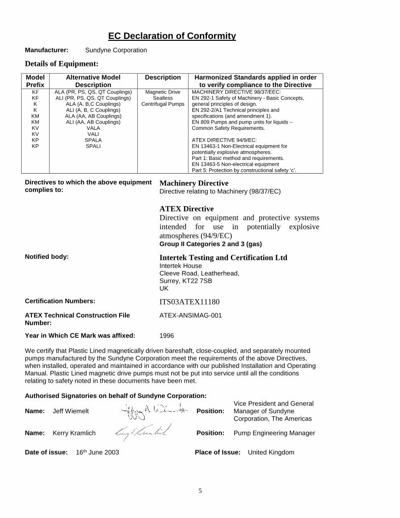
EC Declaration of Conformity
Manufacturer: Sundyne Corporation
Details of Equipment:
ModelPrefix
Alternative ModelDescription
Description Harmonized Standards applied in orderto verify compliance to the Directive
KFKFKK
KMKMKVKVKPKP
ALA (PR, PS, QS, QT Couplings)ALI (PR, PS, QS, QT Couplings)
ALA (A, B,C Couplings)ALI (A, B, C Couplings)ALA (AA, AB Couplings)ALI (AA, AB Couplings)
VALAVALI
SPALASPALI
Magnetic DriveSealless
Centrifugal Pumps
MACHINERY DIRECTIVE 98/37/EEC:EN 292-1 Safety of Machinery - Basic Concepts,general principles of design.EN 292-2/A1 Technical principles andspecifications (and amendment 1).EN 809 Pumps and pump units for liquids –Common Safety Requirements.
ATEX DIRECTIVE 94/9/EC:EN 13463-1 Non-Electrical equipment forpotentially explosive atmospheres.Part 1: Basic method and requirements.EN 13463-5 Non-electrical equipmentPart 5: Protection by constructional safety ‘c’.
Directives to which the above equipmentcomplies to:
Machinery DirectiveDirective relating to Machinery (98/37/EC)
ATEX DirectiveDirective on equipment and protective systemsintended for use in potentially explosiveatmospheres (94/9/EC)Group II Categories 2 and 3 (gas)
Notified body: Intertek Testing and Certification LtdIntertek HouseCleeve Road, Leatherhead,Surrey, KT22 7SBUK
Certification Numbers: ITS03ATEX11180
ATEX Technical Construction FileNumber:
ATEX-ANSIMAG-001
Year in Which CE Mark was affixed: 1996
We certify that Plastic Lined magnetically driven bareshaft, close-coupled, and separately mountedpumps manufactured by the Sundyne Corporation meet the requirements of the above Directives,when installed, operated and maintained in accordance with our published Installation and OperatingManual. Plastic Lined magnetic drive pumps must not be put into service until all the conditionsrelating to safety noted in these documents have been met.
Authorised Signatories on behalf of Sundyne Corporation:
Name: Jeff Wiemelt Position:Vice President and GeneralManager of SundyneCorporation, The Americas
Name: Kerry Kramlich Position: Pump Engineering Manager
Date of issue: 16th June 2003 Place of Issue: United Kingdom

6
SAFETY WARNING
Genuine parts and accessories have been specifically designed and tested for use with these products to ensurecontinued product quality and performance. Testing cannot be performed on all parts nor on accessoriessourced from other vendors, incorrect design and/or fabrication of such parts and accessories may adverselyaffect the performance and safety features of these products. Failure to properly select, install or use authorisedSundyne parts and accessories is considered misuse, and damage or failure caused by misuse is not covered bySundyne’s warranty. Additionally, modification of Sundyne products or removal of original components mayimpair the safety of these products and their effective operation.
EUROPEAN UNION MACHINERY DIRECTIVE(CE mark system)
This document incorporates information relevant to the Machinery Directive 98/37/EC. It should be read priorto the use of any of our equipment. Individual maintenance manuals which also conform to the EU Directiveshould be read when dealing with specific models.
EUROPEAN UNION ATEX DIRECTIVE
This document incorporates information relevant to the ATEX Directive 94/9/EC (Directive on equipment andprotective systems intended for use in potentially explosive atmospheres). It should be read prior to the useof any of our equipment.
Compliance to the Directive is based on Atmospheres having pressures up to but not exceeding 350psi andtemperatures ranging from –120 F to + 250 F depending on the model.
As indicated in the ATEX Directive 94/9/EC, it is the responsibility of the user of the pump to indicate toSundyne LLC the Zone and Corresponding group (Dust or Gas) that the pump is to be installed within.Should the pump be put into service in a potentially explosive atmosphere, the user of the pump must put thegrounding connector into use.
7
CAUTIONRead all instructions before removing pump from shipping container or preparing it for operation. It isimportant to install and operate the pump correctly to eliminate any possible mishap that may bedetrimental to property or personnel. Keep this manual for future reference.
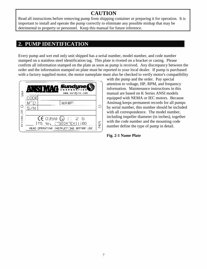
2. PUMP IDENTIFICATION
Every pump and wet end only unit shipped has a serial number, model number, and code numberstamped on a stainless steel identification tag. This plate is riveted on a bracket or casing. Pleaseconfirm all information stamped on the plate as soon as pump is received. Any discrepancy between theorder and the information stamped on plate must be reported to your local dealer. If pump is purchasedwith a factory supplied motor, the motor nameplate must also be checked to verify motor's compatibility
with the pump and the order. Pay specialattention to voltage, HP, RPM, and frequencyinformation. Maintenance instructions in thismanual are based on K Series ANSI modelsequipped with NEMA or IEC motors. BecauseAnsimag keeps permanent records for all pumpsby serial number, this number should be includedwith all correspondence. The model number,including impeller diameter (in inches), togetherwith the code number and the mounting codenumber define the type of pump in detail.
Fig. 2-1 Name Plate
8
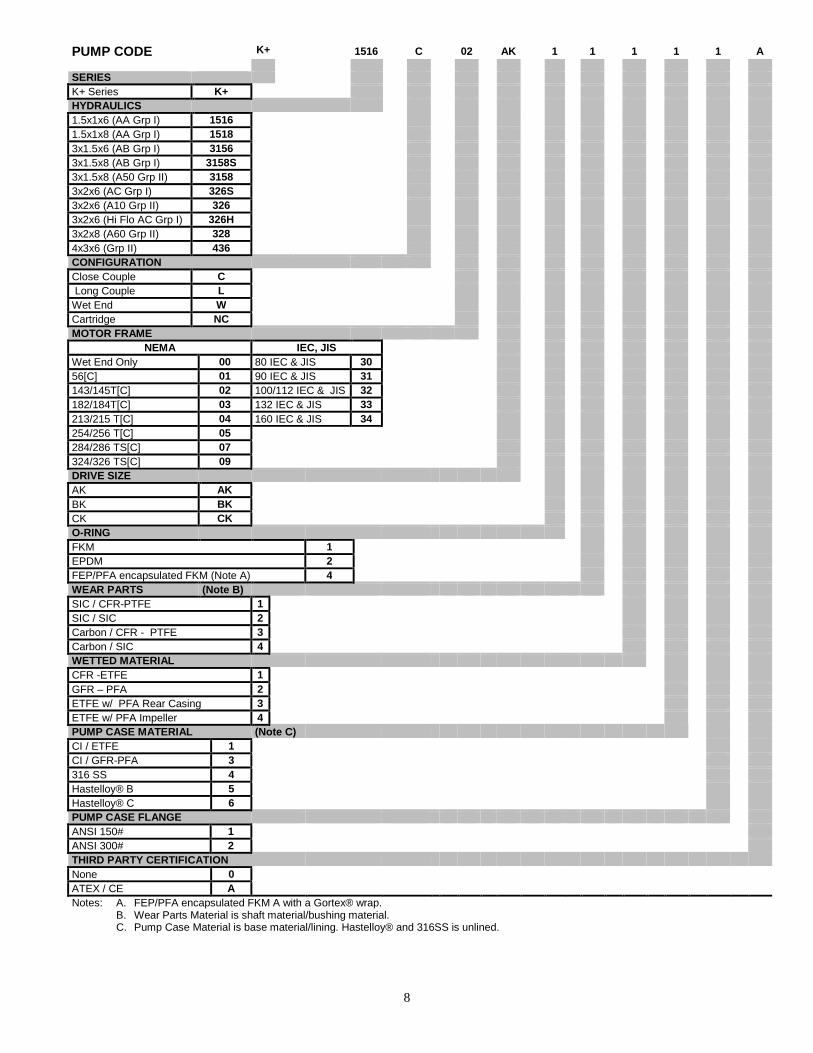
PUMP CODE K+ 1516 C 02 AK 1 1 1 1 1 A
SERIES
K+ Series K+
HYDRAULICS
1.5x1x6 (AA Grp I) 1516
1.5x1x8 (AA Grp I) 1518
3x1.5x6 (AB Grp I) 3156
3x1.5x8 (AB Grp I) 3158S
3x1.5x8 (A50 Grp II) 3158
3x2x6 (AC Grp I) 326S
3x2x6 (A10 Grp II) 326
3x2x6 (Hi Flo AC Grp I) 326H
3x2x8 (A60 Grp II) 328
4x3x6 (Grp II) 436
CONFIGURATION
Close Couple C
Long Couple L
Wet End W
Cartridge NC
MOTOR FRAME
NEMA IEC, JIS
Wet End Only 00 80 IEC & JIS 30
56[C] 01 90 IEC & JIS 31
143/145T[C] 02 100/112 IEC & JIS 32
182/184T[C] 03 132 IEC & JIS 33
213/215 T[C] 04 160 IEC & JIS 34
254/256 T[C] 05
284/286 TS[C] 07
324/326 TS[C] 09
DRIVE SIZE
AK AK
BK BK
CK CK
O-RING
FKM 1
EPDM 2
FEP/PFA encapsulated FKM (Note A) 4
WEAR PARTS (Note B)
SIC / CFR-PTFE 1
SIC / SIC 2
Carbon / CFR - PTFE 3
Carbon / SIC 4
WETTED MATERIAL
CFR -ETFE 1
GFR – PFA 2
ETFE w/ PFA Rear Casing 3
ETFE w/ PFA Impeller 4
PUMP CASE MATERIAL (Note C)
CI / ETFE 1
CI / GFR-PFA 3
316 SS 4
Hastelloy® B 5
Hastelloy® C 6
PUMP CASE FLANGE
ANSI 150# 1
ANSI 300# 2
THIRD PARTY CERTIFICATION
None 0
ATEX / CE A
Notes: A. FEP/PFA encapsulated FKM A with a Gortex® wrap.B. Wear Parts Material is shaft material/bushing material.C. Pump Case Material is base material/lining. Hastelloy® and 316SS is unlined.
9
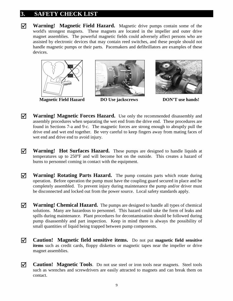
3. SAFETY CHECK LIST
Warning! Magnetic Field Hazard. Magnetic drive pumps contain some of theworld's strongest magnets. These magnets are located in the impeller and outer drivemagnet assemblies. The powerful magnetic fields could adversely affect persons who areassisted by electronic devices that may contain reed switches, and these people should nothandle magnetic pumps or their parts. Pacemakers and defibrillators are examples of thesedevices.
Magnetic Field Hazard DO Use jackscrews DON’T use hands!
Warning! Magnetic Forces Hazard. Use only the recommended disassembly andassembly procedures when separating the wet end from the drive end. These procedures arefound in Sections 7-a and 9-c. The magnetic forces are strong enough to abruptly pull thedrive end and wet end together. Be very careful to keep fingers away from mating faces ofwet end and drive end to avoid injury.
Warning! Hot Surfaces Hazard. These pumps are designed to handle liquids attemperatures up to 250oF and will become hot on the outside. This creates a hazard ofburns to personnel coming in contact with the equipment.
Warning! Rotating Parts Hazard. The pump contains parts which rotate duringoperation. Before operation the pump must have the coupling guard secured in place and becompletely assembled. To prevent injury during maintenance the pump and/or driver mustbe disconnected and locked out from the power source. Local safety standards apply.
Warning! Chemical Hazard. The pumps are designed to handle all types of chemicalsolutions. Many are hazardous to personnel. This hazard could take the form of leaks andspills during maintenance. Plant procedures for decontamination should be followed duringpump disassembly and part inspection. Keep in mind there is always the possibility ofsmall quantities of liquid being trapped between pump components.
Caution! Magnetic field sensitive items. Do not put magnetic field sensitiveitems such as credit cards, floppy diskettes or magnetic tapes near the impeller or drivemagnet assemblies.
Caution! Magnetic Tools. Do not use steel or iron tools near magnets. Steel toolssuch as wrenches and screwdrivers are easily attracted to magnets and can break them oncontact.
10
4. PRINCIPLES OF MAGNETIC DRIVE PUMPS
INNER YOKE OUTER YOKE OUTER MAGNET ASSEMBLY
INNER MAGNET ASSEMBLY
ATTRACTION REPULSION
Fig. 4-1
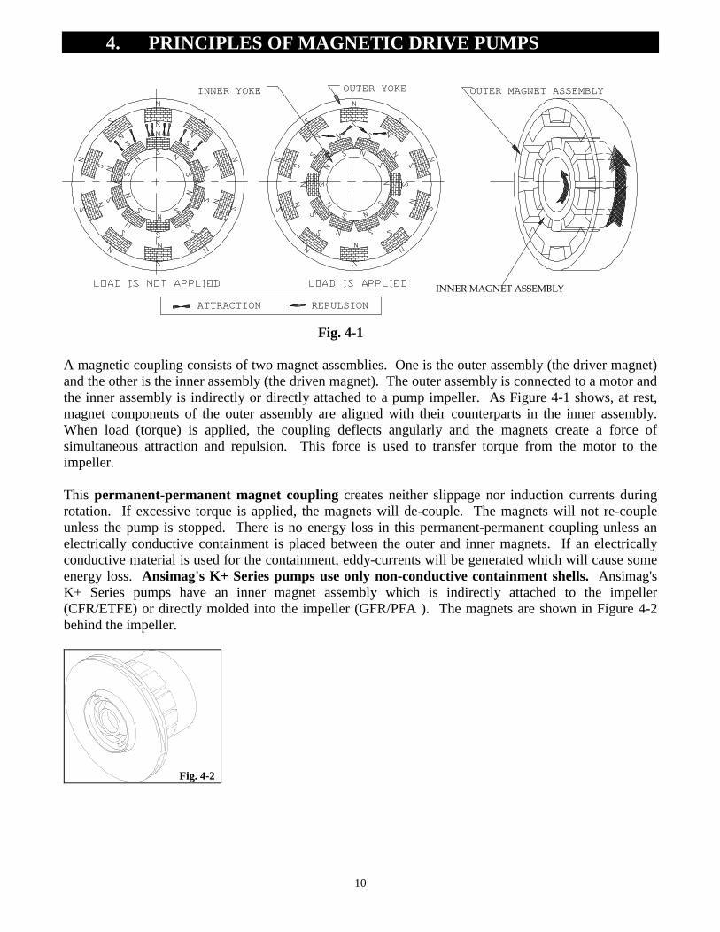
A magnetic coupling consists of two magnet assemblies. One is the outer assembly (the driver magnet)and the other is the inner assembly (the driven magnet). The outer assembly is connected to a motor andthe inner assembly is indirectly or directly attached to a pump impeller. As Figure 4-1 shows, at rest,magnet components of the outer assembly are aligned with their counterparts in the inner assembly.When load (torque) is applied, the coupling deflects angularly and the magnets create a force ofsimultaneous attraction and repulsion. This force is used to transfer torque from the motor to theimpeller.
This permanent-permanent magnet coupling creates neither slippage nor induction currents duringrotation. If excessive torque is applied, the magnets will de-couple. The magnets will not re-coupleunless the pump is stopped. There is no energy loss in this permanent-permanent coupling unless anelectrically conductive containment is placed between the outer and inner magnets. If an electricallyconductive material is used for the containment, eddy-currents will be generated which will cause someenergy loss. Ansimag's K+ Series pumps use only non-conductive containment shells. Ansimag'sK+ Series pumps have an inner magnet assembly which is indirectly attached to the impeller(CFR/ETFE) or directly molded into the impeller (GFR/PFA ). The magnets are shown in Figure 4-2behind the impeller.
Fig. 4-2
11
5. PUMP INSTALLATION
5-a. PIPING
1. Install the pump as close as possible to the suction tank. Pumps are designed to push, not pull,liquid.
2. Ansimag recommends supporting and restraining both the suction and discharge pipes near thepump to avoid the application of forces and moments to the pump casing. All piping should line upwith the pump flanges naturally to minimize any bending moments at the pump nozzles.
3. To minimize friction the suction line should have a short straight run to the pump, and be free offittings, for a length equivalent to or larger than ten (10) times its diameter.
4. The suction line size should be at least as large as the pump's suction port or one size larger if thesuction line is so long that it significantly affects NPSH available. Never reduce the suctionpiping size.
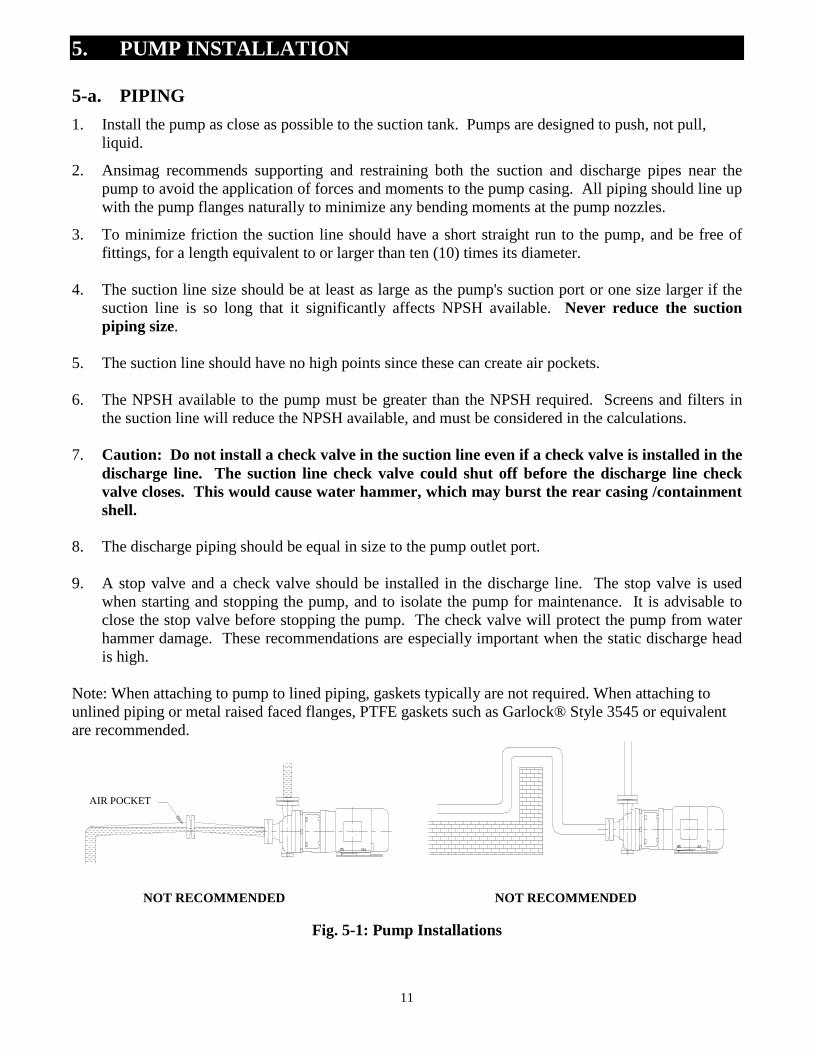
5. The suction line should have no high points since these can create air pockets.
6. The NPSH available to the pump must be greater than the NPSH required. Screens and filters inthe suction line will reduce the NPSH available, and must be considered in the calculations.
7. Caution: Do not install a check valve in the suction line even if a check valve is installed in thedischarge line. The suction line check valve could shut off before the discharge line checkvalve closes. This would cause water hammer, which may burst the rear casing /containmentshell.
8. The discharge piping should be equal in size to the pump outlet port.
9. A stop valve and a check valve should be installed in the discharge line. The stop valve is usedwhen starting and stopping the pump, and to isolate the pump for maintenance. It is advisable toclose the stop valve before stopping the pump. The check valve will protect the pump from waterhammer damage. These recommendations are especially important when the static discharge headis high.
Note: When attaching to pump to lined piping, gaskets typically are not required. When attaching tounlined piping or metal raised faced flanges, PTFE gaskets such as Garlock® Style 3545 or equivalentare recommended.
NOT RECOMMENDED NOT RECOMMENDED
Fig. 5-1: Pump Installations
AIR POCKET
12
5-b. FOUNDATION
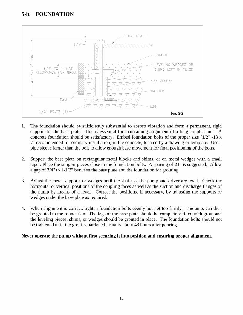
Fig. 5-2
1. The foundation should be sufficiently substantial to absorb vibration and form a permanent, rigidsupport for the base plate. This is essential for maintaining alignment of a long coupled unit. Aconcrete foundation should be satisfactory. Embed foundation bolts of the proper size (1/2" -13 x7" recommended for ordinary installation) in the concrete, located by a drawing or template. Use apipe sleeve larger than the bolt to allow enough base movement for final positioning of the bolts.
2. Support the base plate on rectangular metal blocks and shims, or on metal wedges with a smalltaper. Place the support pieces close to the foundation bolts. A spacing of 24" is suggested. Allowa gap of 3/4" to 1-1/2" between the base plate and the foundation for grouting.
3. Adjust the metal supports or wedges until the shafts of the pump and driver are level. Check thehorizontal or vertical positions of the coupling faces as well as the suction and discharge flanges ofthe pump by means of a level. Correct the positions, if necessary, by adjusting the supports orwedges under the base plate as required.
4. When alignment is correct, tighten foundation bolts evenly but not too firmly. The units can thenbe grouted to the foundation. The legs of the base plate should be completely filled with grout andthe leveling pieces, shims, or wedges should be grouted in place. The foundation bolts should notbe tightened until the grout is hardened, usually about 48 hours after pouring.
Never operate the pump without first securing it into position and ensuring proper alignment.
5-c. INSTALLATION AND ELECTRICAL CONNECTIONS
Ansimag K Series pumps are easily inspected without removing the casing from any piping, byseparating the drive end from the wet-end. In a close-coupled pump this requires moving the motor,drive magnet and bracket backwards and away from the casing. To be able to do this the motor musthave sufficient clearance behind the motor fan cover to move the motor backward approximately 6"[150 mm]. Close-coupled installations should feature the following:
1. Allow at least 6" [150 mm] of clearance behind the motor.
2. The base plate under the motor must be flat and long enough to allow for safe movement of themotor.
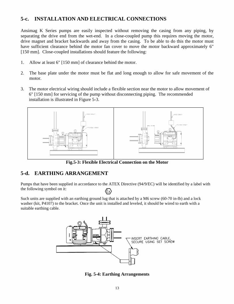
3. The motor electrical wiring should include a flexible section near the motor to allow movement of6" [150 mm] for servicing of the pump without disconnecting piping. The recommendedinstallation is illustrated in Figure 5-3.
Fig.5-3: Flexible Electrical Connection on the Motor
5-d. EARTHING ARRANGEMENT
Pumps that have been supplied in accordance to the ATEX Directive (94/9/EC) will be identified by a label withthe following symbol on it:
Such units are supplied with an earthing ground lug that is attached by a M6 screw (60-70 in-lb) and a lockwasher (kit, P4107) to the bracket. Once the unit is installed and leveled, it should be wired to earth with asuitable earthing cable.
13
Fig. 5-4: Earthing Arrangements
14
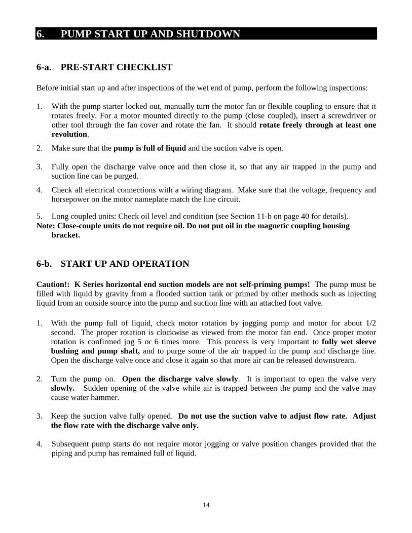
6. PUMP START UP AND SHUTDOWN
6-a. PRE-START CHECKLIST
Before initial start up and after inspections of the wet end of pump, perform the following inspections:
1. With the pump starter locked out, manually turn the motor fan or flexible coupling to ensure that itrotates freely. For a motor mounted directly to the pump (close coupled), insert a screwdriver orother tool through the fan cover and rotate the fan. It should rotate freely through at least onerevolution.
2. Make sure that the pump is full of liquid and the suction valve is open.
3. Fully open the discharge valve once and then close it, so that any air trapped in the pump andsuction line can be purged.
4. Check all electrical connections with a wiring diagram. Make sure that the voltage, frequency andhorsepower on the motor nameplate match the line circuit.
5. Long coupled units: Check oil level and condition (see Section 11-b on page 40 for details).Note: Close-couple units do not require oil. Do not put oil in the magnetic coupling housing
bracket.
6-b. START UP AND OPERATION
Caution!: K Series horizontal end suction models are not self-priming pumps! The pump must befilled with liquid by gravity from a flooded suction tank or primed by other methods such as injectingliquid from an outside source into the pump and suction line with an attached foot valve.
1. With the pump full of liquid, check motor rotation by jogging pump and motor for about 1/2second. The proper rotation is clockwise as viewed from the motor fan end. Once proper motorrotation is confirmed jog 5 or 6 times more. This process is very important to fully wet sleevebushing and pump shaft, and to purge some of the air trapped in the pump and discharge line.Open the discharge valve once and close it again so that more air can be released downstream.
2. Turn the pump on. Open the discharge valve slowly. It is important to open the valve veryslowly. Sudden opening of the valve while air is trapped between the pump and the valve maycause water hammer.
3. Keep the suction valve fully opened. Do not use the suction valve to adjust flow rate. Adjustthe flow rate with the discharge valve only.
4. Subsequent pump starts do not require motor jogging or valve position changes provided that thepiping and pump has remained full of liquid.
15
Caution! Do not run the pump dry. The pump may be severely damaged. The pumps use slidebearings that are lubricated by the pumped product. No lubrication, no bearings. Even shortperiods of dry running could damage the pump.
Caution! Do not Dead Head. Although the radial loads on the bearings are not a concern, theliquid in the pump will rapidly increase in temperature. This will continue until the boiling point isreached. Some liquids boil at temperatures sufficient to melt pump components and destroy themagnets. Other liquids will flash into vapor. This vapor collects at the bushing causing dryrunning.
Caution! Mag Drive Mismatch. Do not use inner and outer magnet assemblies with unlikedrives (AK with BK, CK with AK, etc.). Mismatch of drives will prevent coupling from occurringand will damage the pump. Typically, the pump will make a loud buzzing noise with little or noflow and head developed.
Caution! Cavitation. Prolonged cavitation may cause pitting on the pump components. Short termsevere cavitation, such as that caused by a closed suction will damage the pump bearings.
Caution! Water Hammer. Sudden changes in fluid velocity can cause large, rapid pressuresurges. These pressure surges can damage the pump, piping and instrumentation. Typical causesare rapidly closing valves. Check valves on the suction can also cause water hammer if the liquidhas time to reverse direction before the valve closes.
Recommended! Power Monitors. We recommend installing a power monitor on all pumps.These devices are very effective at protecting the pumps from dry running, cavitation or whenfrequent overload is expected. They are also very effective for stoppage during tank unloadingapplications.
Dry Running Pump Seizure Closed Valve Severe Cavitation Clogged Suction Filter Excess (High) Flow
6-c. SHUTDOWN
If the pump is to be shut down for any reason, use the following procedure:
1. Close the discharge valve slowly to prevent water hammer.
2. Shut off the motor.
3. Close the suction valve.
16
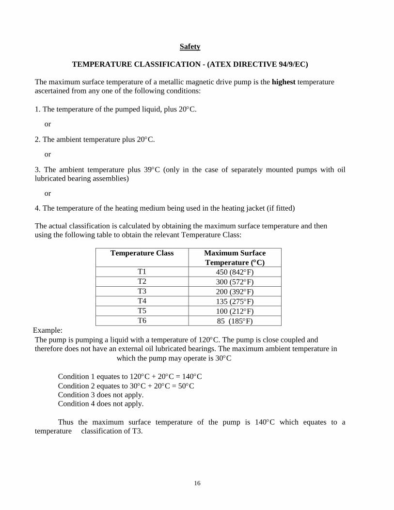
Safety
TEMPERATURE CLASSIFICATION - (ATEX DIRECTIVE 94/9/EC)
The maximum surface temperature of a metallic magnetic drive pump is the highest temperatureascertained from any one of the following conditions:
1. The temperature of the pumped liquid, plus 20C.
or
2. The ambient temperature plus 20C.
or
3. The ambient temperature plus 39C (only in the case of separately mounted pumps with oillubricated bearing assemblies)
or
4. The temperature of the heating medium being used in the heating jacket (if fitted)
The actual classification is calculated by obtaining the maximum surface temperature and thenusing the following table to obtain the relevant Temperature Class:
Temperature Class Maximum SurfaceTemperature (C)
T1 450 (842F)T2 300 (572F)T3 200 (392F)T4 135 (275F)T5 100 (212F)T6 85 (185F)
Example:The pump is pumping a liquid with a temperature of 120C. The pump is close coupled andtherefore does not have an external oil lubricated bearings. The maximum ambient temperature in
which the pump may operate is 30C
Condition 1 equates to 120C + 20C = 140CCondition 2 equates to 30C + 20C = 50CCondition 3 does not apply.Condition 4 does not apply.
Thus the maximum surface temperature of the pump is 140C which equates to atemperature classification of T3.
17
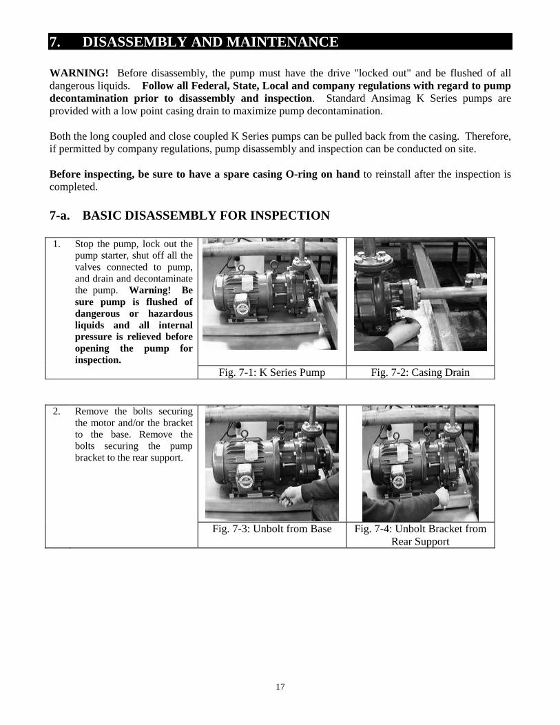
7. DISASSEMBLY AND MAINTENANCE
WARNING! Before disassembly, the pump must have the drive "locked out" and be flushed of alldangerous liquids. Follow all Federal, State, Local and company regulations with regard to pumpdecontamination prior to disassembly and inspection. Standard Ansimag K Series pumps areprovided with a low point casing drain to maximize pump decontamination.
Both the long coupled and close coupled K Series pumps can be pulled back from the casing. Therefore,if permitted by company regulations, pump disassembly and inspection can be conducted on site.
Before inspecting, be sure to have a spare casing O-ring on hand to reinstall after the inspection iscompleted.
7-a. BASIC DISASSEMBLY FOR INSPECTION
1. Stop the pump, lock out thepump starter, shut off all thevalves connected to pump,and drain and decontaminatethe pump. Warning! Besure pump is flushed ofdangerous or hazardousliquids and all internalpressure is relieved beforeopening the pump forinspection.
Fig. 7-1: K Series Pump Fig. 7-2: Casing Drain
2. Remove the bolts securingthe motor and/or the bracketto the base. Remove thebolts securing the pumpbracket to the rear support.
Fig. 7-3: Unbolt from Base Fig. 7-4: Unbolt Bracket fromRear Support
18
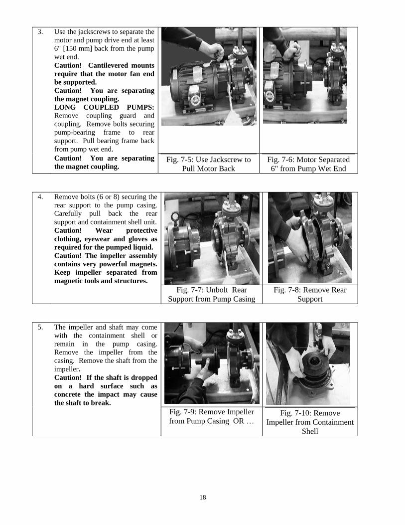
3. Use the jackscrews to separate themotor and pump drive end at least6" [150 mm] back from the pumpwet end.Caution! Cantilevered mountsrequire that the motor fan endbe supported.Caution! You are separatingthe magnet coupling.LONG COUPLED PUMPS:Remove coupling guard andcoupling. Remove bolts securingpump-bearing frame to rearsupport. Pull bearing frame backfrom pump wet end.Caution! You are separatingthe magnet coupling.
Fig. 7-5: Use Jackscrew toPull Motor Back
Fig. 7-6: Motor Separated6" from Pump Wet End
4. Remove bolts (6 or 8) securing therear support to the pump casing.Carefully pull back the rearsupport and containment shell unit.Caution! Wear protectiveclothing, eyewear and gloves asrequired for the pumped liquid.Caution! The impeller assemblycontains very powerful magnets.Keep impeller separated frommagnetic tools and structures.
Fig. 7-7: Unbolt RearSupport from Pump Casing
Fig. 7-8: Remove RearSupport
5. The impeller and shaft may comewith the containment shell orremain in the pump casing.Remove the impeller from thecasing. Remove the shaft from theimpeller.Caution! If the shaft is droppedon a hard surface such asconcrete the impact may causethe shaft to break.
Fig. 7-9: Remove Impellerfrom Pump Casing OR …
Fig. 7-10: RemoveImpeller from Containment
Shell
19
7-b. INSPECTION CHECKLIST
Since most wearing parts on a mag drive pump cannot be monitored, it is important to inspect the pumpfor wear after the initial 500 hours or three months of operation, whichever comes first. Inspect again insix or twelve months, depending on the results of the first inspection.
Before inspecting, be sure to have a spare casing O-ring on hand to reinstall after the inspection iscompleted. To inspect the pump interior, be sure that the pump has first been flushed of all dangerousliquids.
Operating conditions vary so widely that recommending one schedule of preventive maintenance for allcentrifugal pumps is not possible. In the case of magnetic drive pumps, particularly of non-metallicpumps, traditional maintenance techniques such as vibration monitoring are not useful or reliablefor wet end preventive maintenance. These techniques are effective only for bearing frames (non-liquid contact components) and for motor bearings. For best maintenance results, keep a record ofactual operating data such as flow, pressure, motor load, and hours of operation. The length of the safeoperation period will vary with different applications and can be determined only from experience.
The inspection checklist is as follows:
1. Check for cracks in silicon carbide parts such as the thrust ring and shaft.
2. Check for signs of melting or deforming in the shaft support, bushing and the socket of thecontainment shell where the pump shaft is held. Dry-running during initial startup or duringoperation may cause heat-related deflection or wear of these parts.
3. Inspect the casing liner to be sure there are no signs of abrasion or cuts deeper than 0.05" [1.3 mm].Liner cracks may occur if the lining is corroded or placed in an extremely cold place, or if achemical penetrates the liner and corrodes the outside metal casing. Most liner damage can bespotted visually. To detect hairline cracks, a 15-20 KV electrostatic discharge tester isrecommended, which is often used to test lined pipe.
4. The 1.25" carbon bushing should be checked for wear and scoring or grooving. The dimensions aregiven in Section 7-c. The 1.25" SiC bushing will not exhibit wear under normal operation.Polishing on SiC surfaces is a normal condition of running and does not require replacement.However, the inner surface must be checked for cracks, chips or scratches. Verify that the mainbushing is tightly pressed into the impeller. It should be impossible to dislodge the bushing byhand. Check for signs of melting around the circumference of the main bushing.
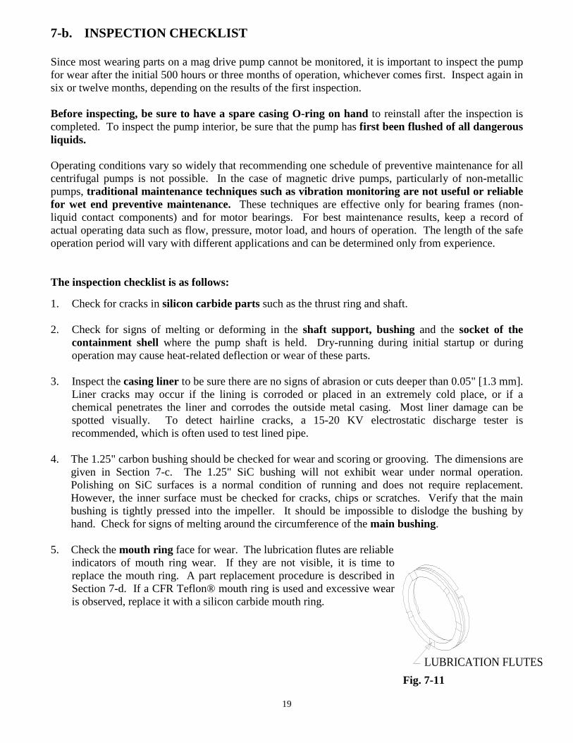
5. Check the mouth ring face for wear. The lubrication flutes are reliableindicators of mouth ring wear. If they are not visible, it is time toreplace the mouth ring. A part replacement procedure is described inSection 7-d. If a CFR Teflon® mouth ring is used and excessive wearis observed, replace it with a silicon carbide mouth ring.
LUBRICATION FLUTES
Fig. 9-1
Fig. 7-11
20
6. Check the impeller vanes for material trapped inside. If any of the flow paths become clogged, ahydrodynamic imbalance may cause excessive wear to the mouth ring and main bushing.
7. Check the inner magnet encapsulation for cracks or grooves in excess of 1/32" [0.8mm]. Fluidinside the magnet area may cause swelling which could wear on the containment shell.
8. Where applicable, check impeller and inner drive lugs for looseness or swelling due to plasticdeformation. If necessary, removal of the bushing and separation of the impeller and inner driveare required to further inspect the impeller snap fit tabs and contact surfaces of the drive lugs.Replace the impeller if the snap fit tabs or drive lugs are visibly cracked or deformed. Replace theinner drive if the drive lug contact surfaces are swollen or deformed. Note: See Parts ReplacementProcedures for additional instruction and tooling.
9. Check for slurry. If the pumped liquid contains slurry, it may build up near the back of the mainbushing. This build-up may cause clogging of the journal bearing area of the main bushing andcreate a dry-run condition. Estimate the rate of build-up from the first inspection and schedule theunit for future maintenance accordingly.mm
10. Inspect the containment shell for signs of abrasion. Replace if scratches or grooves in the innersurface are deeper than 1/32" [0.8mm]. Also replace if the outside has grooves deeper than 0.020[0.5mm] inches. Inspect the back thrust ring for chips or cracks.
21
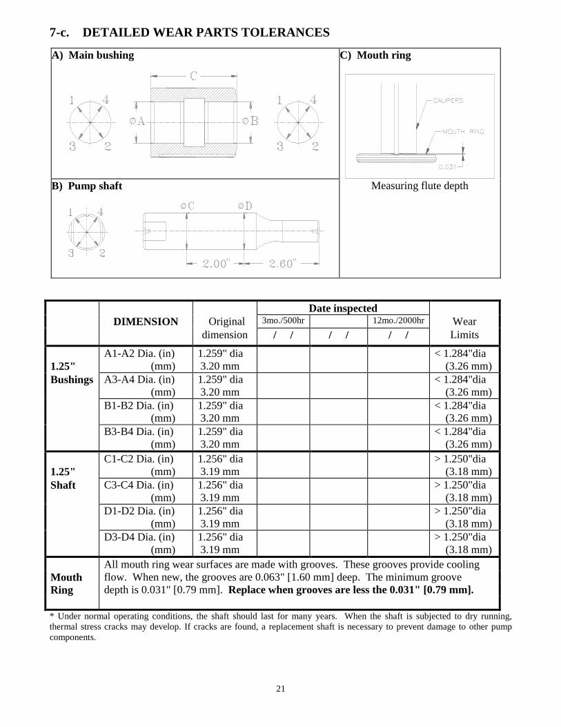
7-c. DETAILED WEAR PARTS TOLERANCES
A) Main bushing C) Mouth ring
B) Pump shaft Measuring flute depth
Date inspectedDIMENSION Original 3mo./500hr 12mo./2000hr Wear
dimension / / / / / / Limits
1.25"A1-A2 Dia. (in)
(mm)1.259" dia3.20 mm
< 1.284"dia(3.26 mm)
Bushings A3-A4 Dia. (in)(mm)
1.259" dia3.20 mm
< 1.284"dia(3.26 mm)
B1-B2 Dia. (in)(mm)
1.259" dia3.20 mm
< 1.284"dia(3.26 mm)
B3-B4 Dia. (in)(mm)
1.259" dia3.20 mm
< 1.284"dia(3.26 mm)
1.25"C1-C2 Dia. (in)
(mm)1.256" dia3.19 mm
> 1.250"dia(3.18 mm)
Shaft C3-C4 Dia. (in)(mm)
1.256" dia3.19 mm
> 1.250"dia(3.18 mm)
D1-D2 Dia. (in)(mm)
1.256" dia3.19 mm
> 1.250"dia(3.18 mm)
D3-D4 Dia. (in)(mm)
1.256" dia3.19 mm
> 1.250"dia(3.18 mm)
All mouth ring wear surfaces are made with grooves. These grooves provide coolingMouth flow. When new, the grooves are 0.063" [1.60 mm] deep. The minimum grooveRing depth is 0.031" [0.79 mm]. Replace when grooves are less the 0.031" [0.79 mm].
* Under normal operating conditions, the shaft should last for many years. When the shaft is subjected to dry running,thermal stress cracks may develop. If cracks are found, a replacement shaft is necessary to prevent damage to other pumpcomponents.
22
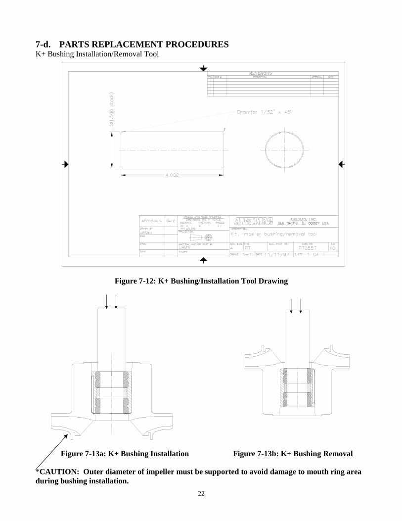
7-d. PARTS REPLACEMENT PROCEDURESK+ Bushing Installation/Removal Tool
Figure 7-12: K+ Bushing/Installation Tool Drawing
Figure 7-13a: K+ Bushing Installation Figure 7-13b: K+ Bushing Removal
*CAUTION: Outer diameter of impeller must be supported to avoid damage to mouth ring areaduring bushing installation.
23
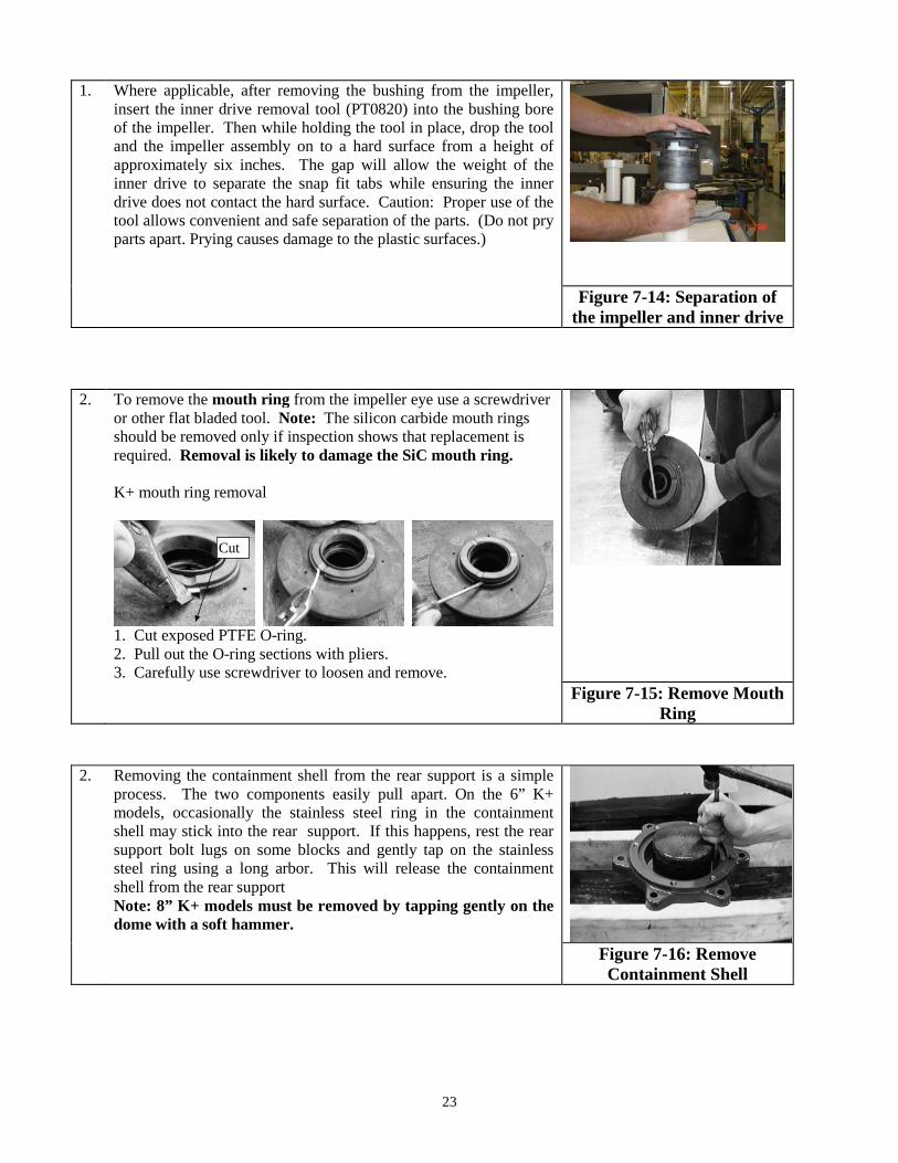
1. Where applicable, after removing the bushing from the impeller,insert the inner drive removal tool (PT0820) into the bushing boreof the impeller. Then while holding the tool in place, drop the tooland the impeller assembly on to a hard surface from a height ofapproximately six inches. The gap will allow the weight of theinner drive to separate the snap fit tabs while ensuring the innerdrive does not contact the hard surface. Caution: Proper use of thetool allows convenient and safe separation of the parts. (Do not pryparts apart. Prying causes damage to the plastic surfaces.)
Figure 7-14: Separation ofthe impeller and inner drive
2. To remove the mouth ring from the impeller eye use a screwdriveror other flat bladed tool. Note: The silicon carbide mouth ringsshould be removed only if inspection shows that replacement isrequired. Removal is likely to damage the SiC mouth ring.
K+ mouth ring removal
1. Cut exposed PTFE O-ring.2. Pull out the O-ring sections with pliers.3. Carefully use screwdriver to loosen and remove.
Figure 7-15: Remove MouthRing
2. Removing the containment shell from the rear support is a simpleprocess. The two components easily pull apart. On the 6” K+models, occasionally the stainless steel ring in the containmentshell may stick into the rear support. If this happens, rest the rearsupport bolt lugs on some blocks and gently tap on the stainlesssteel ring using a long arbor. This will release the containmentshell from the rear supportNote: 8” K+ models must be removed by tapping gently on thedome with a soft hammer.
Figure 7-16: RemoveContainment Shell
Cut
24
8. WET END ASSEMBLY
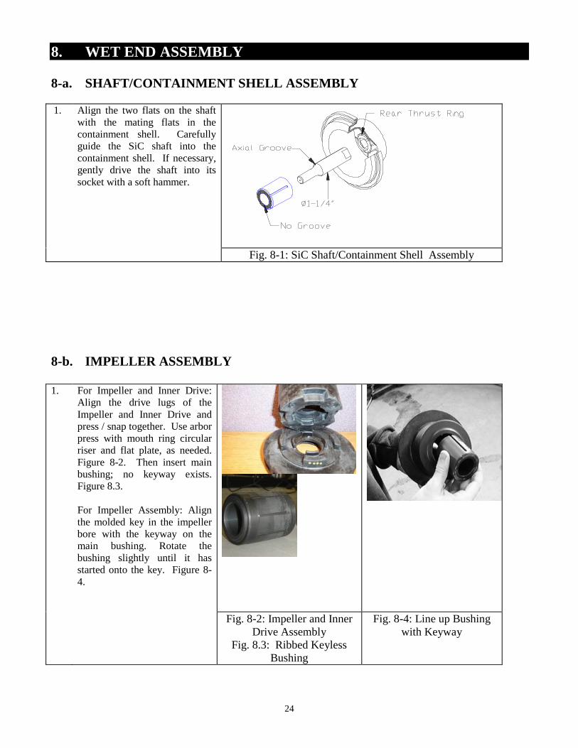
8-a. SHAFT/CONTAINMENT SHELL ASSEMBLY
1. Align the two flats on the shaftwith the mating flats in thecontainment shell. Carefullyguide the SiC shaft into thecontainment shell. If necessary,gently drive the shaft into itssocket with a soft hammer.
Fig. 8-1: SiC Shaft/Containment Shell Assembly
8-b. IMPELLER ASSEMBLY
1. For Impeller and Inner Drive:Align the drive lugs of theImpeller and Inner Drive andpress / snap together. Use arborpress with mouth ring circularriser and flat plate, as needed.Figure 8-2. Then insert mainbushing; no keyway exists.Figure 8.3.
For Impeller Assembly: Alignthe molded key in the impellerbore with the keyway on themain bushing. Rotate thebushing slightly until it hasstarted onto the key. Figure 8-4.
Fig. 8-2: Impeller and InnerDrive Assembly
Fig. 8.3: Ribbed KeylessBushing
Fig. 8-4: Line up Bushingwith Keyway
25
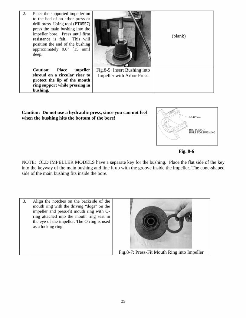
2. Place the supported impeller onto the bed of an arbor press ordrill press. Using tool (PT0557)press the main bushing into theimpeller bore. Press until firmresistance is felt. This willposition the end of the bushingapproximately 0.6" [15 mm]deep.
(blank)
Caution: Place impellershroud on a circular riser toprotect the lip of the mouthring support while pressing inbushing.
Fig.8-5: Insert Bushing intoImpeller with Arbor Press
Caution: Do not use a hydraulic press, since you can not feelwhen the bushing hits the bottom of the bore!
Fig. 8-6
NOTE: OLD IMPELLER MODELS have a separate key for the bushing. Place the flat side of the keyinto the keyway of the main bushing and line it up with the groove inside the impeller. The cone-shapedside of the main bushing fits inside the bore.
3. Align the notches on the backside of themouth ring with the driving “dogs” on theimpeller and press-fit mouth ring with O-ring attached into the mouth ring seat inthe eye of the impeller. The O-ring is usedas a locking ring.
Fig.8-7: Press-Fit Mouth Ring into Impeller
2-1/8"bore
BOTTOM OFBORE FOR BUSHING
Fig. 11-4
26
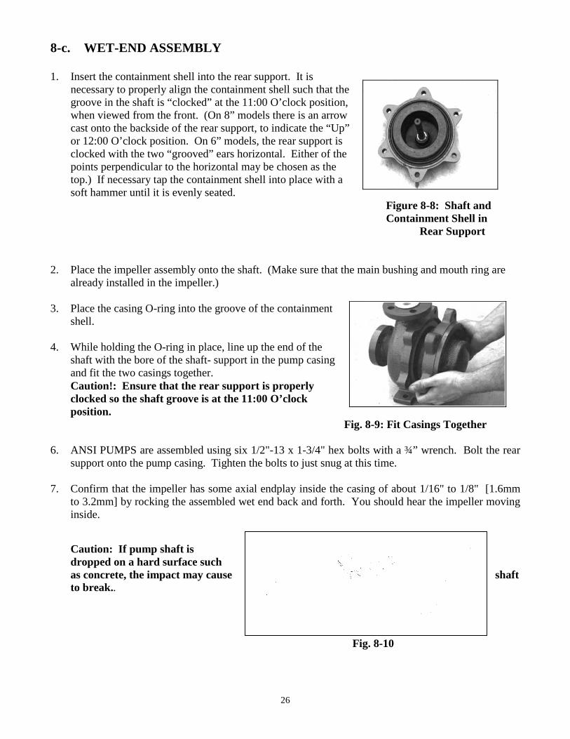
8-c. WET-END ASSEMBLY
1. Insert the containment shell into the rear support. It isnecessary to properly align the containment shell such that thegroove in the shaft is “clocked” at the 11:00 O’clock position,when viewed from the front. (On 8” models there is an arrowcast onto the backside of the rear support, to indicate the “Up”or 12:00 O’clock position. On 6” models, the rear support isclocked with the two “grooved” ears horizontal. Either of thepoints perpendicular to the horizontal may be chosen as thetop.) If necessary tap the containment shell into place with asoft hammer until it is evenly seated.
Figure 8-8: Shaft andContainment Shell in
Rear Support
2. Place the impeller assembly onto the shaft. (Make sure that the main bushing and mouth ring arealready installed in the impeller.)
3. Place the casing O-ring into the groove of the containmentshell.
4. While holding the O-ring in place, line up the end of theshaft with the bore of the shaft- support in the pump casingand fit the two casings together.Caution!: Ensure that the rear support is properlyclocked so the shaft groove is at the 11:00 O’clockposition.
Fig. 8-9: Fit Casings Together
6. ANSI PUMPS are assembled using six 1/2"-13 x 1-3/4" hex bolts with a ¾” wrench. Bolt the rearsupport onto the pump casing. Tighten the bolts to just snug at this time.
7. Confirm that the impeller has some axial endplay inside the casing of about 1/16" to 1/8" [1.6mmto 3.2mm] by rocking the assembled wet end back and forth. You should hear the impeller movinginside.
Caution: If pump shaft isdropped on a hard surface suchas concrete, the impact may cause shaftto break..
Fig. 8-10
27
9. DRIVE END ASSEMBLY (ANSI Pumps with NEMA Motors)
9-a. MOUNTING OUTER DRIVE TO MOTOR OR BEARING FRAME SHAFT
1. Place the motor vertically on the worktable or floor so that the shaft is pointing upwards. Be sure tocover the work surface with corrugated cardboard or similar material to prevent damage to the fancover.
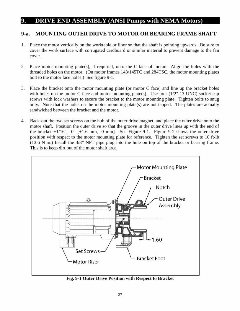
2. Place motor mounting plate(s), if required, onto the C-face of motor. Align the holes with thethreaded holes on the motor. (On motor frames 143/145TC and 284TSC, the motor mounting platesbolt to the motor face holes.) See figure 9-1.
3. Place the bracket onto the motor mounting plate (or motor C face) and line up the bracket holeswith holes on the motor C-face and motor mounting plate(s). Use four (1/2"-13 UNC) socket capscrews with lock washers to secure the bracket to the motor mounting plate. Tighten bolts to snugonly. Note that the holes on the motor mounting plate(s) are not tapped. The plates are actuallysandwiched between the bracket and the motor.
4. Back-out the two set screws on the hub of the outer drive magnet, and place the outer drive onto themotor shaft. Position the outer drive so that the groove in the outer drive lines up with the end ofthe bracket +1/16", -0" [+1.6 mm, -0 mm]. See Figure 9-1. Figure 9-2 shows the outer driveposition with respect to the motor mounting plate for reference. Tighten the set screws to 10 ft-lb(13.6 N-m.) Install the 3/8” NPT pipe plug into the hole on top of the bracket or bearing frame.This is to keep dirt out of the motor shaft area.
Fig. 9-1 Outer Drive Position with Respect to Bracket
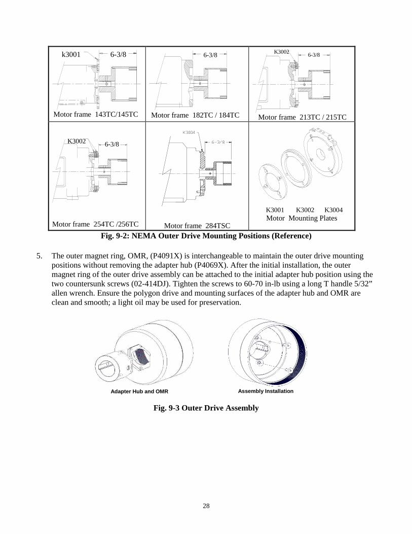
k3001 6-3/8
Motor frame 143TC/145TC
6-3/8
Motor frame 182TC / 184TC
K30026-3/8
Motor frame 213TC / 215TC
K3002 6-3/8
Motor frame 254TC /256TC Motor frame 284TSC
K3001 K3002 K3004Motor Mounting Plates
Fig. 9-2: NEMA Outer Drive Mounting Positions (Reference)
5. The outer magnet ring, OMR, (P4091X) is interchangeable to maintain the outer drive mountingpositions without removing the adapter hub (P4069X). After the initial installation, the outermagnet ring of the outer drive assembly can be attached to the initial adapter hub position using thetwo countersunk screws (02-414DJ). Tighten the screws to 60-70 in-lb using a long T handle 5/32”allen wrench. Ensure the polygon drive and mounting surfaces of the adapter hub and OMR areclean and smooth; a light oil may be used for preservation.
28
Fig. 9-3 Outer Drive As
Adapter Hub and OMR
sembly
Assembly Installation
29
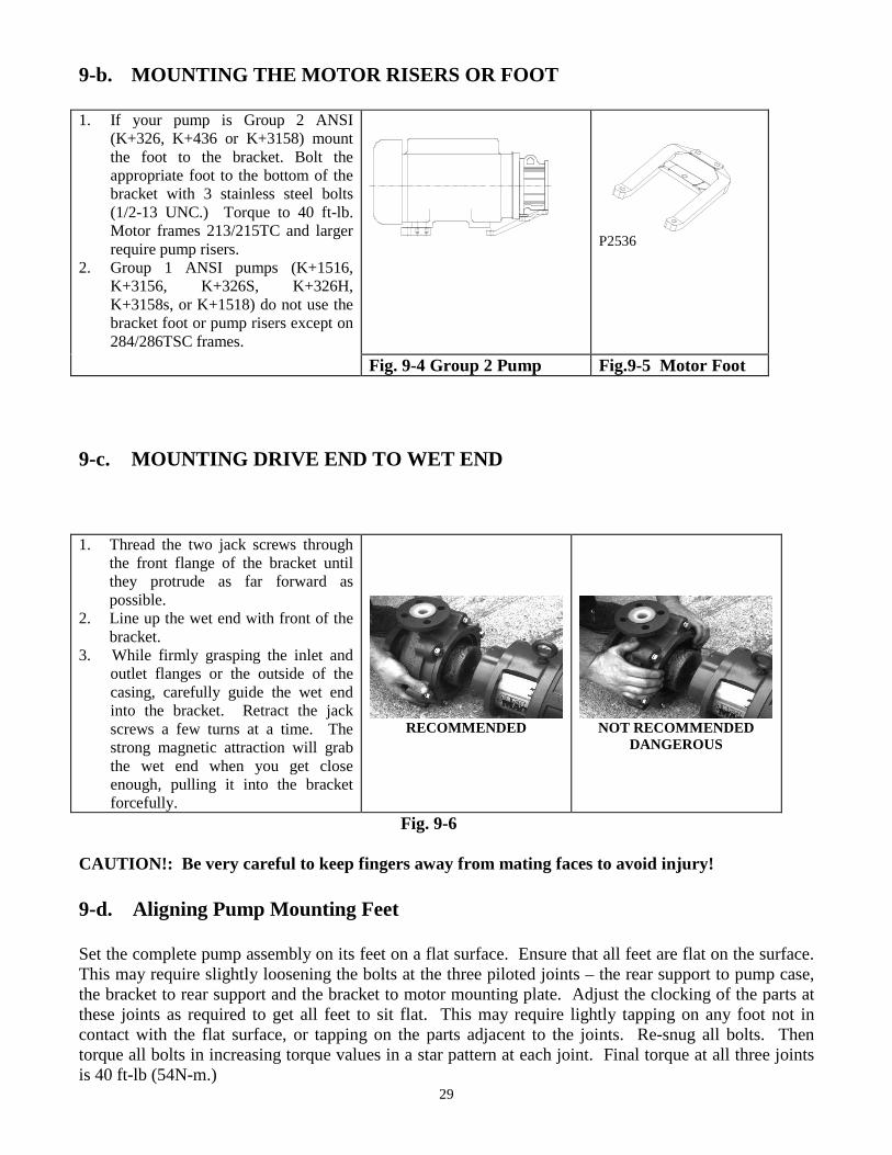
9-b. MOUNTING THE MOTOR RISERS OR FOOT
1. If your pump is Group 2 ANSI(K+326, K+436 or K+3158) mountthe foot to the bracket. Bolt theappropriate foot to the bottom of thebracket with 3 stainless steel bolts(1/2-13 UNC.) Torque to 40 ft-lb.Motor frames 213/215TC and largerrequire pump risers.
2. Group 1 ANSI pumps (K+1516,K+3156, K+326S, K+326H,K+3158s, or K+1518) do not use thebracket foot or pump risers except on284/286TSC frames.
P2536
Fig. 9-4 Group 2 Pump Fig.9-5 Motor Foot
9-c. MOUNTING DRIVE END TO WET END
1. Thread the two jack screws throughthe front flange of the bracket untilthey protrude as far forward aspossible.
2. Line up the wet end with front of thebracket.
3. While firmly grasping the inlet andoutlet flanges or the outside of thecasing, carefully guide the wet endinto the bracket. Retract the jackscrews a few turns at a time. Thestrong magnetic attraction will grabthe wet end when you get closeenough, pulling it into the bracketforcefully.
RECOMMENDED NOT RECOMMENDEDDANGEROUS
Fig. 9-6
CAUTION!: Be very careful to keep fingers away from mating faces to avoid injury!
9-d. Aligning Pump Mounting Feet
Set the complete pump assembly on its feet on a flat surface. Ensure that all feet are flat on the surface.This may require slightly loosening the bolts at the three piloted joints – the rear support to pump case,the bracket to rear support and the bracket to motor mounting plate. Adjust the clocking of the parts atthese joints as required to get all feet to sit flat. This may require lightly tapping on any foot not incontact with the flat surface, or tapping on the parts adjacent to the joints. Re-snug all bolts. Thentorque all bolts in increasing torque values in a star pattern at each joint. Final torque at all three jointsis 40 ft-lb (54N-m.)
10. DRIVE END ASSEMBLY (ANSI PUMPS WITH IEC MOTORS)(-B5 FLANGE ONLY)
10-a. MOUNTING ADAPTER, OUTER DRIVE AND FOOT
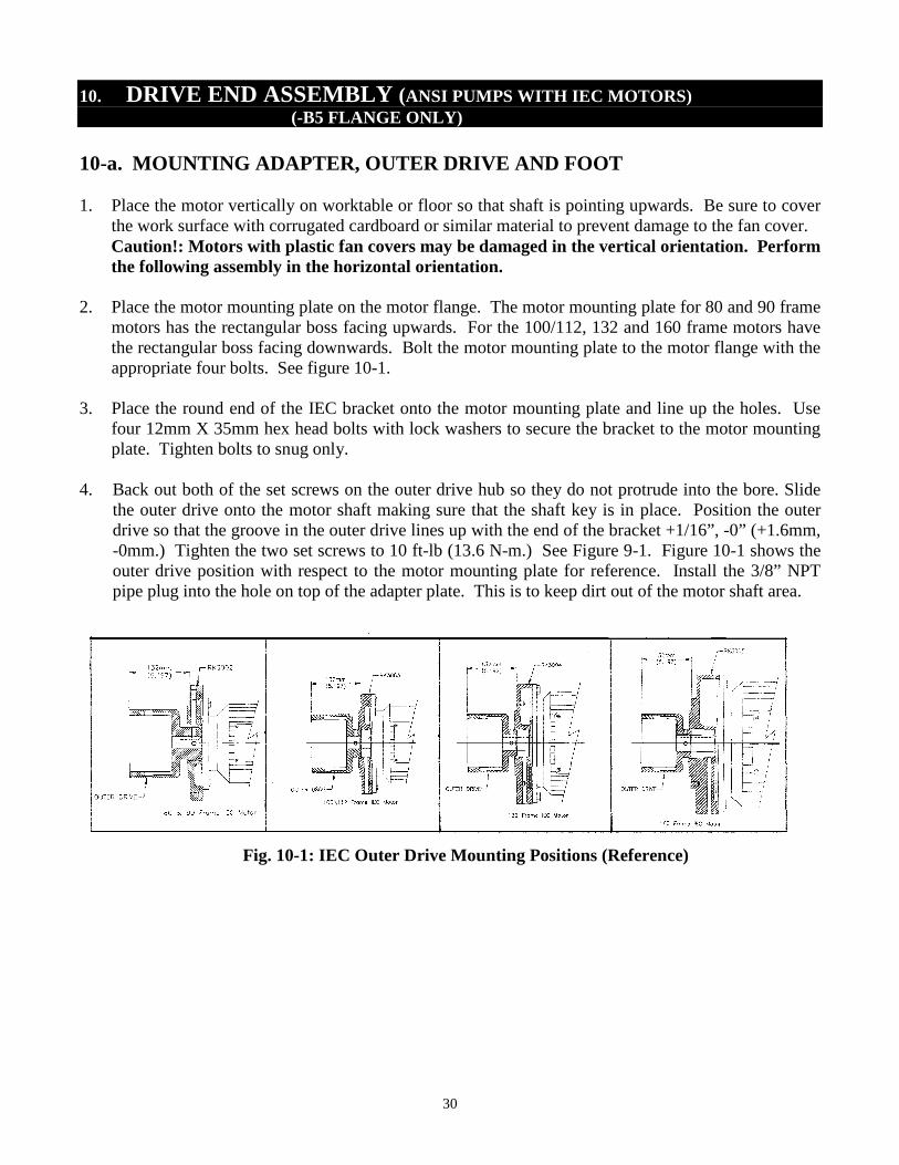
1. Place the motor vertically on worktable or floor so that shaft is pointing upwards. Be sure to coverthe work surface with corrugated cardboard or similar material to prevent damage to the fan cover.Caution!: Motors with plastic fan covers may be damaged in the vertical orientation. Performthe following assembly in the horizontal orientation.
2. Place the motor mounting plate on the motor flange. The motor mounting plate for 80 and 90 framemotors has the rectangular boss facing upwards. For the 100/112, 132 and 160 frame motors havethe rectangular boss facing downwards. Bolt the motor mounting plate to the motor flange with theappropriate four bolts. See figure 10-1.
3. Place the round end of the IEC bracket onto the motor mounting plate and line up the holes. Usefour 12mm X 35mm hex head bolts with lock washers to secure the bracket to the motor mountingplate. Tighten bolts to snug only.
4. Back out both of the set screws on the outer drive hub so they do not protrude into the bore. Slidethe outer drive onto the motor shaft making sure that the shaft key is in place. Position the outerdrive so that the groove in the outer drive lines up with the end of the bracket +1/16”, -0” (+1.6mm,-0mm.) Tighten the two set screws to 10 ft-lb (13.6 N-m.) See Figure 9-1. Figure 10-1 shows theouter drive position with respect to the motor mounting plate for reference. Install the 3/8” NPTpipe plug into the hole on top of the adapter plate. This is to keep dirt out of the motor shaft area.
30
Fig. 10-1: IEC Outer Drive Mounting Positions (Reference)
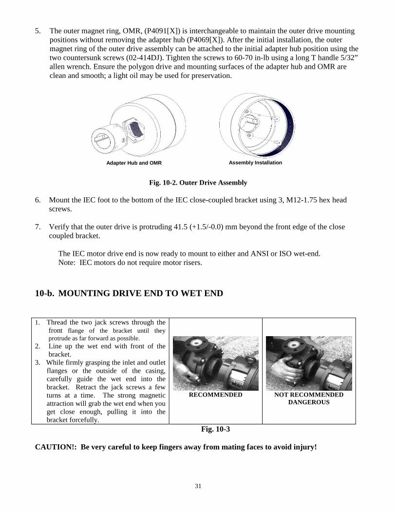
5. The outer magnet ring, OMR, (P4091[X]) is interchangeable to maintain the outer drive mountingpositions without removing the adapter hub (P4069[X]). After the initial installation, the outermagnet ring of the outer drive assembly can be attached to the initial adapter hub position using thetwo countersunk screws (02-414DJ). Tighten the screws to 60-70 in-lb using a long T handle 5/32”allen wrench. Ensure the polygon drive and mounting surfaces of the adapter hub and OMR areclean and smooth; a light oil may be used for preservation.
6. Mount tscrews.
7. Verify tcoupled
The INote
10-b. MO
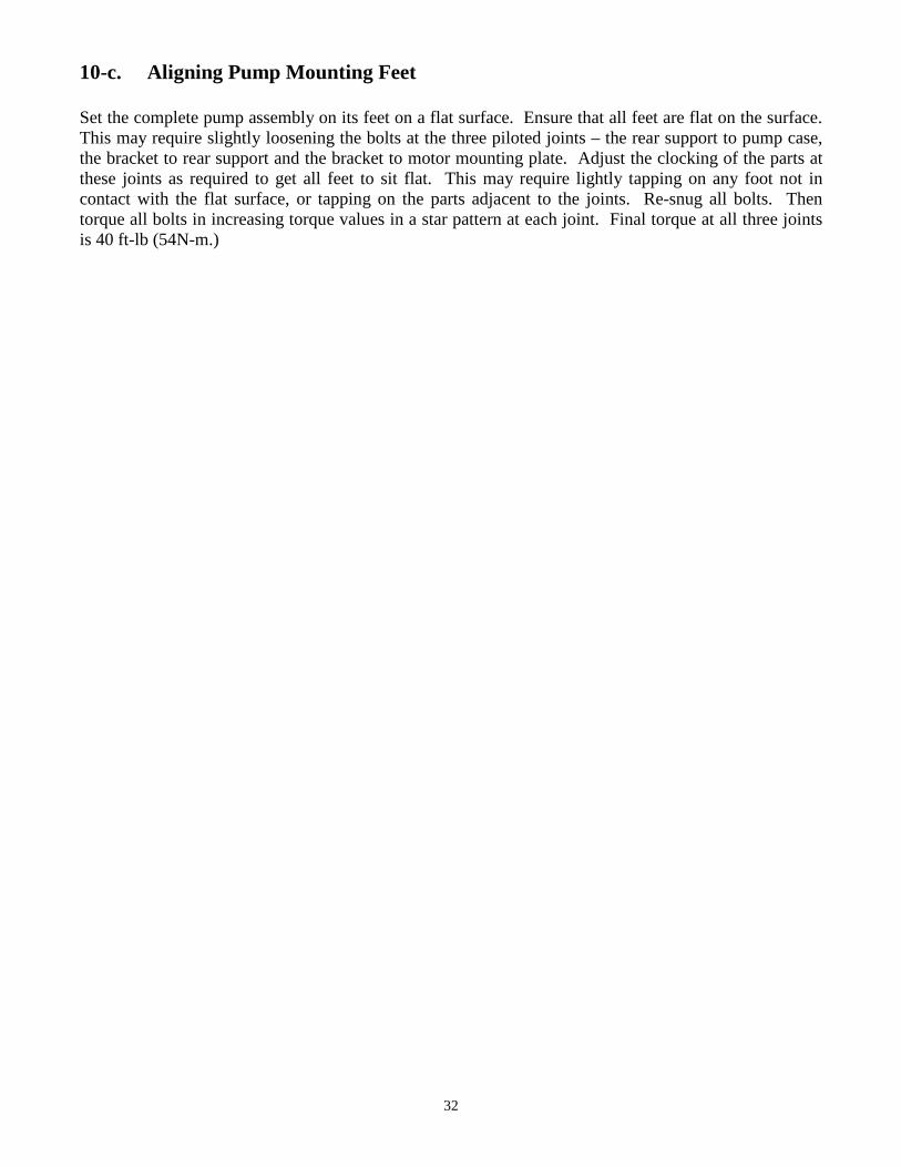
1. Thread thfront flaprotrude a
2. Line upbracket.
3. While firmflanges ocarefullybracket.turns atattractionget closebracket fo
CAUTION!
31
Fig. 10-2. Outer Drive As
he IEC foot to the bottom of the IEC close-coupl
hat the outer drive is protruding 41.5 (+1.5/-0.0)bracket.
EC motor drive end is now ready to mount to eit: IEC motors do not require motor risers.
UNTING DRIVE END TO WET END
e two jack screws through thenge of the bracket until theys far forward as possible.
the wet end with front of the
ly grasping the inlet and outletr the outside of the casing,guide the wet end into theRetract the jack screws a few
a time. The strong magneticwill grab the wet end when you
enough, pulling it into thercefully.
RECOMME
Fig. 10-
: Be very careful to keep fingers away from m
Adapter Hub and OMR
sembly
ed bracket using 3, M12-1.75 hex head
mm beyond the front edge of the close
her and ANSI or ISO wet-end.
NDED NOT RECOMMENDEDDANGEROUS
3
ating faces to avoid injury!
Assembly Installation
32
10-c. Aligning Pump Mounting Feet
Set the complete pump assembly on its feet on a flat surface. Ensure that all feet are flat on the surface.This may require slightly loosening the bolts at the three piloted joints – the rear support to pump case,the bracket to rear support and the bracket to motor mounting plate. Adjust the clocking of the parts atthese joints as required to get all feet to sit flat. This may require lightly tapping on any foot not incontact with the flat surface, or tapping on the parts adjacent to the joints. Re-snug all bolts. Thentorque all bolts in increasing torque values in a star pattern at each joint. Final torque at all three jointsis 40 ft-lb (54N-m.)
11. TRIMMING IMPELLERS
Assembly Instructions
Fig. 11-1 Fig. 11-2 Fig. 11-3
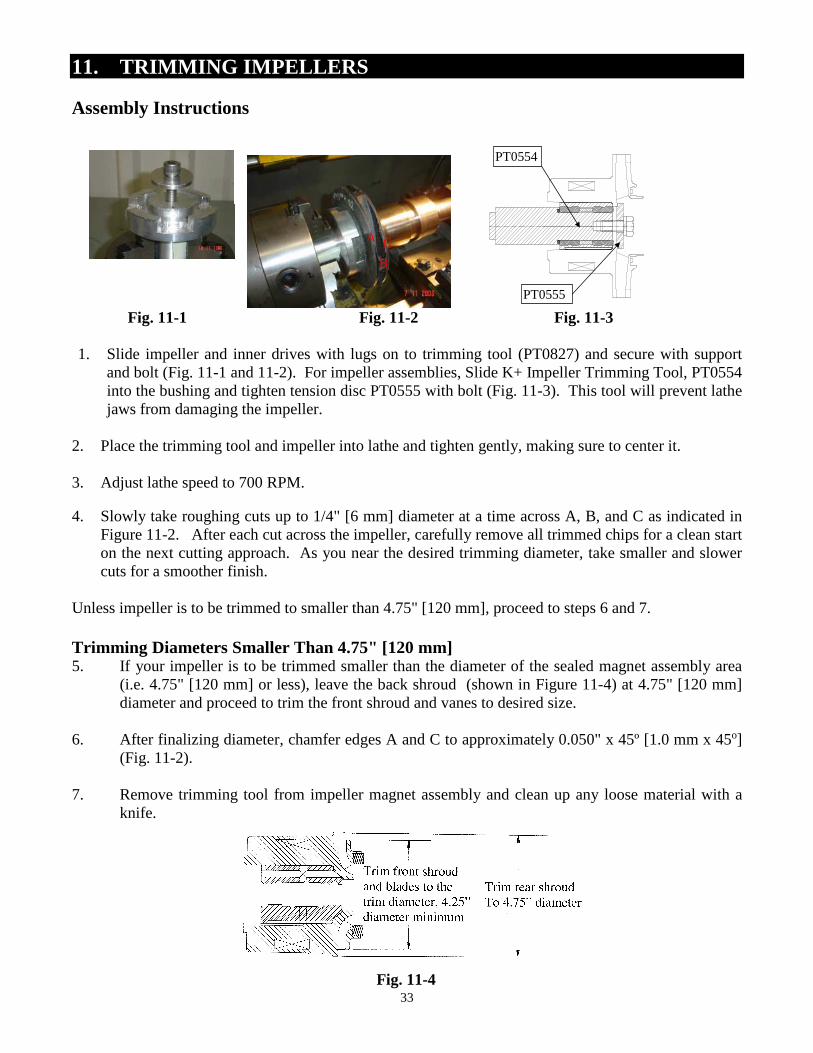
1. Slide impeller and inner drives with lugs on to trimming tool (PT0827) and secure with supportand bolt (Fig. 11-1 and 11-2). For impeller assemblies, Slide K+ Impeller Trimming Tool, PT0554into the bushing and tighten tension disc PT0555 with bolt (Fig. 11-3). This tool will prevent lathejaws from damaging the impeller.
2. Place the trimming tool and impeller into lathe and tighten gently, making sure to center it.
3. Adjust lathe speed to 700 RPM.
4. Slowly take roughing cuts up to 1/4" [6 mm] diameter at a time across A, B, and C as indicated inFigure 11-2. After each cut across the impeller, carefully remove all trimmed chips for a clean starton the next cutting approach. As you near the desired trimming diameter, take smaller and slowercuts for a smoother finish.
Unless impeller is to be trimmed to smaller than 4.75" [120 mm], proceed to steps 6 and 7.
Trimming Diameters Smaller Than 4.75" [120 mm]5. If your impeller is to be trimmed smaller than the diameter of the sealed magnet assembly area
(i.e. 4.75" [120 mm] or less), leave the back shroud (shown in Figure 11-4) at 4.75" [120 mm]diameter and proceed to trim the front shroud and vanes to desired size.
6. After finalizing diameter, chamfer edges A and C to approximately 0.050" x 45º [1.0 mm x 45o](Fig. 11-2).
7. Remove trimming tool from impeller magnet assembly and clean up any loose material with aknife.
PT0554
PT0555
A
B
C
33
Fig. 11-4
34
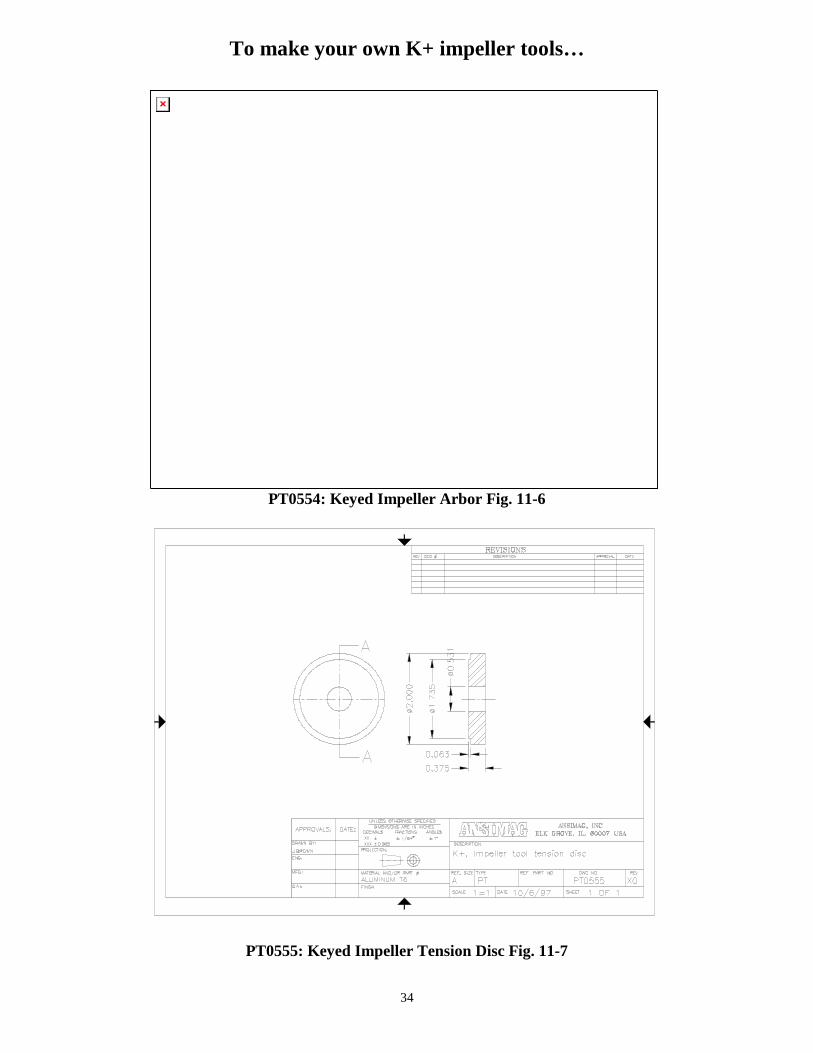
To make your own K+ impeller tools…
PT0554: Keyed Impeller Arbor Fig. 11-6
PT0555: Keyed Impeller Tension Disc Fig. 11-7
35
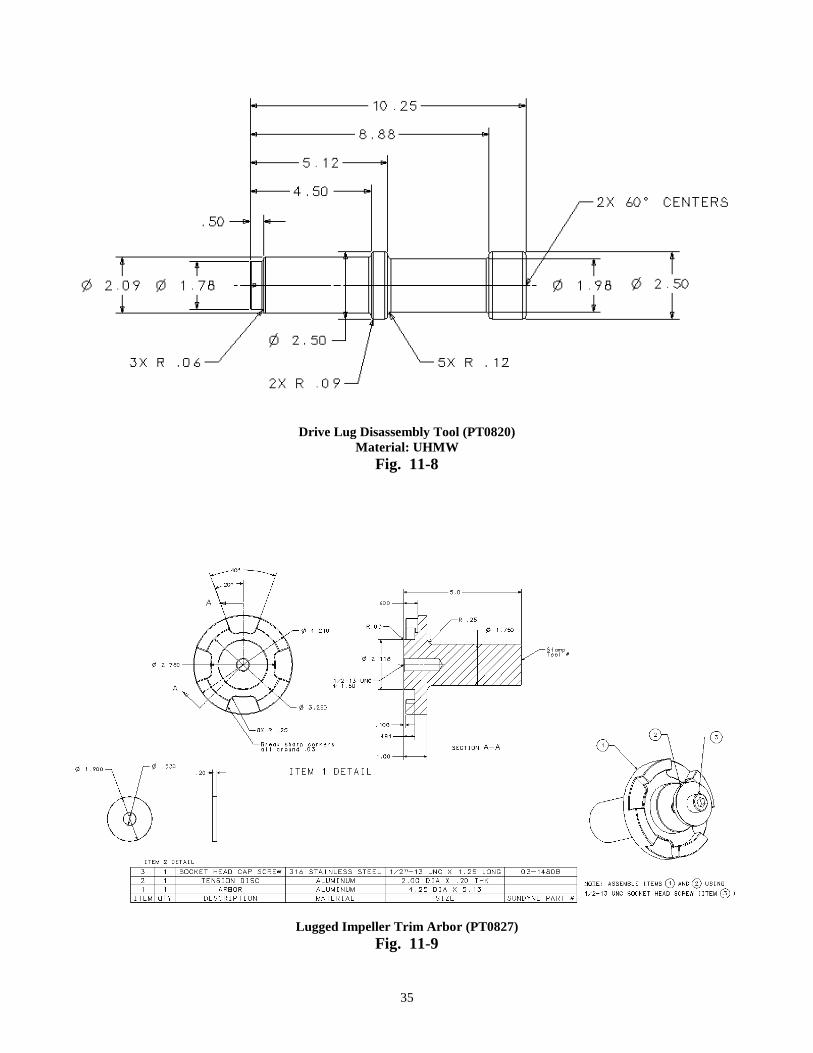
Drive Lug Disassembly Tool (PT0820)Material: UHMW
Fig. 11-8
Lugged Impeller Trim Arbor (PT0827)
Fig. 11-9
36
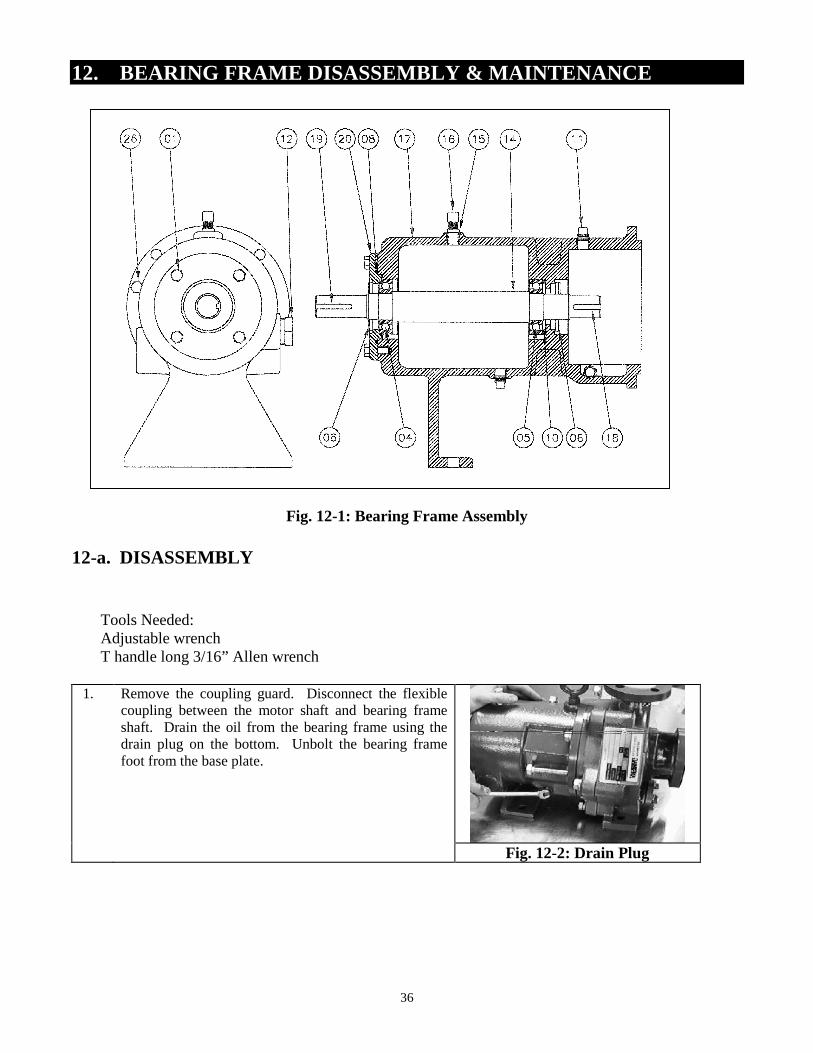
12. BEARING FRAME DISASSEMBLY & MAINTENANCE
Fig. 12-1: Bearing Frame Assembly
12-a. DISASSEMBLY
Tools Needed:Adjustable wrenchT handle long 3/16” Allen wrench
1. Remove the coupling guard. Disconnect the flexiblecoupling between the motor shaft and bearing frameshaft. Drain the oil from the bearing frame using thedrain plug on the bottom. Unbolt the bearing framefoot from the base plate.
Fig. 12-2: Drain Plug
37
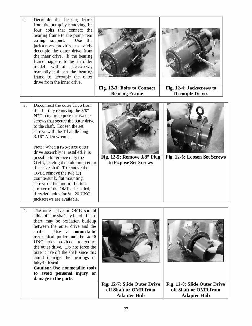
2. Decouple the bearing framefrom the pump by removing thefour bolts that connect thebearing frame to the pump rearcasing support. Use thejackscrews provided to safelydecouple the outer drive fromthe inner drive. If the bearingframe happens to be an oldermodel without jackscrews,manually pull on the bearingframe to decouple the outerdrive from the inner drive.
Fig. 12-3: Bolts to ConnectBearing Frame
Fig. 12-4: Jackscrews toDecouple Drives
3. Disconnect the outer drive fromthe shaft by removing the 3/8”NPT plug to expose the two setscrews that secure the outer driveto the shaft. Loosen the setscrews with the T handle long3/16” Allen wrench.
Note: When a two-piece outerdrive assembly is installed, it ispossible to remove only theOMR, leaving the hub mounted tothe drive shaft. To remove theOMR, remove the two (2)countersunk, flat mountingscrews on the interior bottomsurface of the OMR. If needed,threaded holes for ¼ - 20 UNCjackscrews are available.
Fig. 12-5: Remove 3/8” Plugto Expose Set Screws
Fig. 12-6: Loosen Set Screws
4. The outer drive or OMR shouldslide off the shaft by hand. If notthere may be oxidation buildupbetween the outer drive and theshaft. Use a nonmetallicmechanical puller and the ¼-20UNC holes provided to extractthe outer drive. Do not force theouter drive off the shaft since thiscould damage the bearings orlabyrinth seal.Caution: Use nonmetallic toolsto avoid personal injury ordamage to the parts.
Fig. 12-7: Slide Outer Driveoff Shaft or OMR from
Adapter Hub
Fig. 12-8: Slide Outer Driveoff Shaft or OMR from
Adapter Hub
38
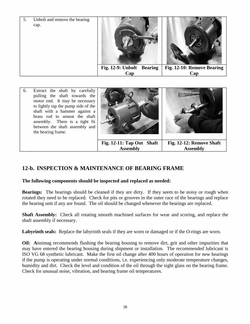
5. Unbolt and remove the bearingcap.
Fig. 12-9: Unbolt BearingCap
Fig. 12-10: Remove BearingCap
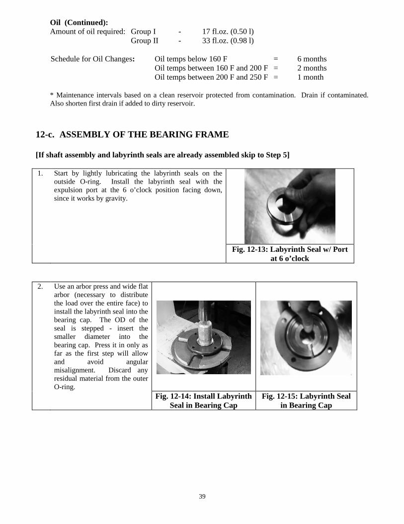
6. Extract the shaft by carefullypulling the shaft towards themotor end. It may be necessaryto lightly tap the pump side of theshaft with a hammer against abrass rod to unseat the shaftassembly. There is a tight fitbetween the shaft assembly andthe bearing frame.
Fig. 12-11: Tap Out ShaftAssembly
Fig. 12-12: Remove ShaftAssembly
12-b. INSPECTION & MAINTENANCE OF BEARING FRAME
The following components should be inspected and replaced as needed:
Bearings: The bearings should be cleaned if they are dirty. If they seem to be noisy or rough whenrotated they need to be replaced. Check for pits or grooves in the outer race of the bearings and replacethe bearing unit if any are found. The oil should be changed whenever the bearings are replaced.
Shaft Assembly: Check all rotating smooth machined surfaces for wear and scoring, and replace theshaft assembly if necessary.
Labyrinth seals: Replace the labyrinth seals if they are worn or damaged or if the O-rings are worn.
Oil: Ansimag recommends flushing the bearing housing to remove dirt, grit and other impurities thatmay have entered the bearing housing during shipment or installation. The recommended lubricant isISO VG 68 synthetic lubricant. Make the first oil change after 400 hours of operation for new bearingsif the pump is operating under normal conditions, i.e. experiencing only moderate temperature changes,humidity and dirt. Check the level and condition of the oil through the sight glass on the bearing frame.Check for unusual noise, vibration, and bearing frame oil temperatures.
39
Oil (Continued):Amount of oil required: Group I - 17 fl.oz. (0.50 l)
Group II - 33 fl.oz. (0.98 l)
Schedule for Oil Changes: Oil temps below 160 F = 6 monthsOil temps between 160 F and 200 F = 2 monthsOil temps between 200 F and 250 F = 1 month
* Maintenance intervals based on a clean reservoir protected from contamination. Drain if contaminated.Also shorten first drain if added to dirty reservoir.
12-c. ASSEMBLY OF THE BEARING FRAME
[If shaft assembly and labyrinth seals are already assembled skip to Step 5]
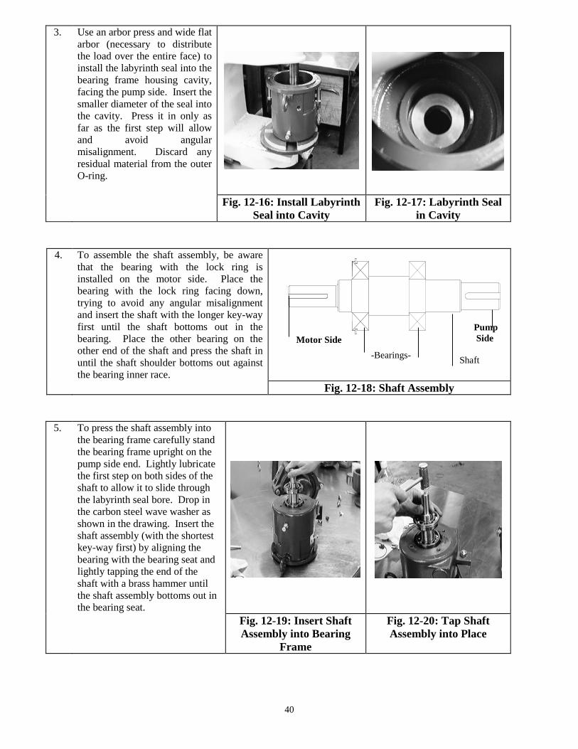
1. Start by lightly lubricating the labyrinth seals on theoutside O-ring. Install the labyrinth seal with theexpulsion port at the 6 o’clock position facing down,since it works by gravity.
Fig. 12-13: Labyrinth Seal w/ Portat 6 o’clock
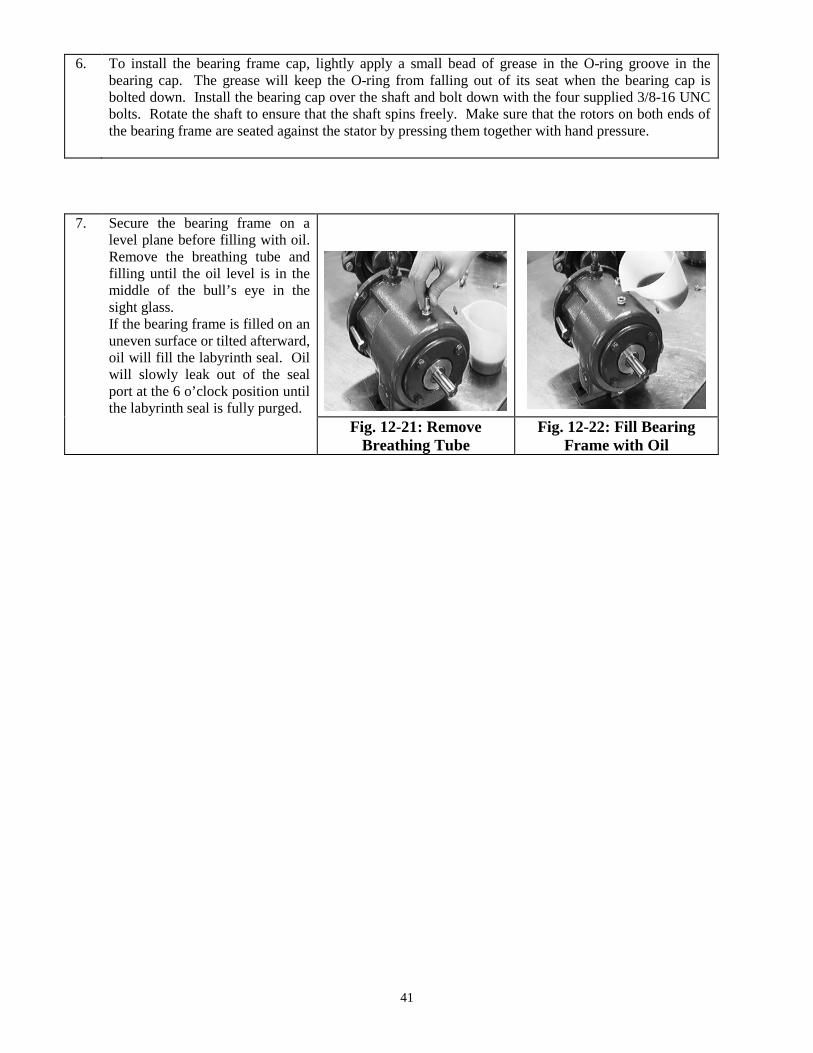
2. Use an arbor press and wide flatarbor (necessary to distributethe load over the entire face) toinstall the labyrinth seal into thebearing cap. The OD of theseal is stepped - insert thesmaller diameter into thebearing cap. Press it in only asfar as the first step will allowand avoid angularmisalignment. Discard anyresidual material from the outerO-ring.
Fig. 12-14: Install LabyrinthSeal in Bearing Cap
Fig. 12-15: Labyrinth Sealin Bearing Cap
40
3. Use an arbor press and wide flatarbor (necessary to distributethe load over the entire face) toinstall the labyrinth seal into thebearing frame housing cavity,facing the pump side. Insert thesmaller diameter of the seal intothe cavity. Press it in only asfar as the first step will allowand avoid angularmisalignment. Discard anyresidual material from the outerO-ring.
Fig. 12-16: Install LabyrinthSeal into Cavity
Fig. 12-17: Labyrinth Sealin Cavity
4. To assemble the shaft assembly, be awarethat the bearing with the lock ring isinstalled on the motor side. Place thebearing with the lock ring facing down,trying to avoid any angular misalignmentand insert the shaft with the longer key-wayfirst until the shaft bottoms out in thebearing. Place the other bearing on theother end of the shaft and press the shaft inuntil the shaft shoulder bottoms out againstthe bearing inner race.
Fig. 12-18: Shaft Assembly
5. To press the shaft assembly intothe bearing frame carefully standthe bearing frame upright on thepump side end. Lightly lubricatethe first step on both sides of theshaft to allow it to slide throughthe labyrinth seal bore. Drop inthe carbon steel wave washer asshown in the drawing. Insert theshaft assembly (with the shortestkey-way first) by aligning thebearing with the bearing seat andlightly tapping the end of theshaft with a brass hammer untilthe shaft assembly bottoms out inthe bearing seat.
Fig. 12-19: Insert ShaftAssembly into Bearing
Frame
Fig. 12-20: Tap ShaftAssembly into Place
-Bearings-
PumpSide
Shaft
Motor Side
41
6. To install the bearing frame cap, lightly apply a small bead of grease in the O-ring groove in thebearing cap. The grease will keep the O-ring from falling out of its seat when the bearing cap isbolted down. Install the bearing cap over the shaft and bolt down with the four supplied 3/8-16 UNCbolts. Rotate the shaft to ensure that the shaft spins freely. Make sure that the rotors on both ends ofthe bearing frame are seated against the stator by pressing them together with hand pressure.
7. Secure the bearing frame on alevel plane before filling with oil.Remove the breathing tube andfilling until the oil level is in themiddle of the bull’s eye in thesight glass.If the bearing frame is filled on anuneven surface or tilted afterward,oil will fill the labyrinth seal. Oilwill slowly leak out of the sealport at the 6 o’clock position untilthe labyrinth seal is fully purged.
Fig. 12-21: RemoveBreathing Tube
Fig. 12-22: Fill BearingFrame with Oil

13. PARTS LIST
42
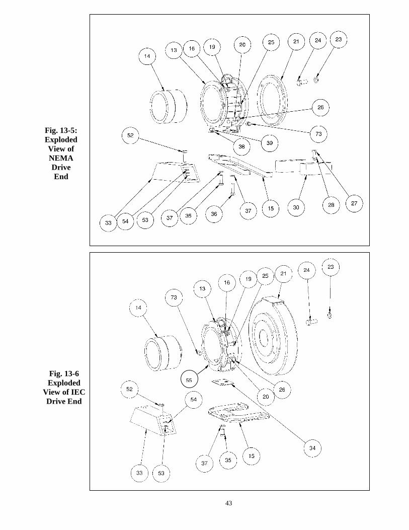
Fig. 13-5:ExplodedView ofNEMADriveEnd
Fig. 13-6Exploded
View of IECDrive End
55
43
44
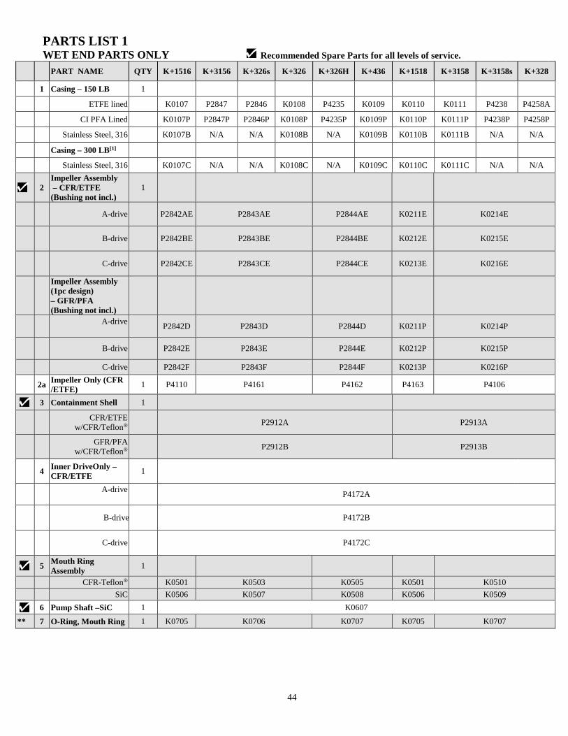
PARTS LIST 1WET END PARTS ONLY Recommended Spare Parts for all levels of service.
PART NAME QTY K+1516 K+3156 K+326s K+326 K+326H K+436 K+1518 K+3158 K+3158s K+328
1 Casing – 150 LB 1
ETFE lined K0107 P2847 P2846 K0108 P4235 K0109 K0110 K0111 P4238 P4258A
CI PFA Lined K0107P P2847P P2846P K0108P P4235P K0109P K0110P K0111P P4238P P4258P
Stainless Steel, 316 K0107B N/A N/A K0108B N/A K0109B K0110B K0111B N/A N/A
Casing – 300 LB[1]
Stainless Steel, 316 K0107C N/A N/A K0108C N/A K0109C K0110C K0111C N/A N/A
2Impeller Assembly– CFR/ETFE
(Bushing not incl.)1
A-drive P2842AE P2843AE P2844AE K0211E K0214E
B-drive P2842BE P2843BE P2844BE K0212E K0215E
C-drive P2842CE P2843CE P2844CE K0213E K0216E
Impeller Assembly(1pc design)– GFR/PFA(Bushing not incl.)
A-driveP2842D P2843D P2844D K0211P K0214P
B-drive P2842E P2843E P2844E K0212P K0215P
C-drive P2842F P2843F P2844F K0213P K0216P
2aImpeller Only (CFR/ETFE)
1 P4110 P4161 P4162 P4163 P4106
3 Containment Shell 1
CFR/ETFEw/CFR/Teflon® P2912A P2913A
GFR/PFAw/CFR/Teflon® P2912B P2913B
4Inner DriveOnly –CFR/ETFE
1
A-driveP4172A
B-drive P4172B
C-drive P4172C
5Mouth RingAssembly
1
CFR-Teflon® K0501 K0503 K0505 K0501 K0510
SiC K0506 K0507 K0508 K0506 K0509
6 Pump Shaft –SiC 1 K0607
** 7 O-Ring, Mouth Ring 1 K0705 K0706 K0707 K0705 K0707
45
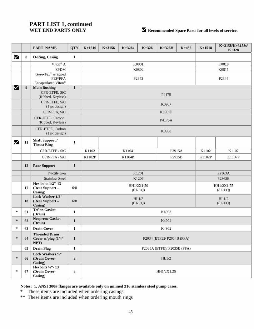
PART LIST 1, continuedWET END PARTS ONLY Recommended Spare Parts for all levels of service.
Notes: 1. ANSI 300# flanges are available only on unlined 316 stainless steel pump cases.
* These items are included when ordering casings** These items are included when ordering mouth rings
PART NAME QTY K+1516 K+3156 K+326s K+326 K+326H K+436 K+1518K+3158/K+3158s/
K+328
8 O-Ring, Casing 1
Viton® A K0801 K0810
EPDM K0802 K0811
Gore-Tex® wrappedFEP/PFA
Encapsulated Viton®P2343 P2344
9 Main Bushing 1
CFR-ETFE, SiC(Ribbed, Keyless)
P4175
CFR-ETFE, SiC(1 pc design)
K0907
GFR-PFA, SiC K0907P
CFR-ETFE, Carbon(Ribbed, Keyless)
P4175A
CFR-ETFE, Carbon(1 pc design)
K0908
11Shaft Support /Thrust Ring
1
CFR-ETFE / SiC K1102 K1104 P2915A K1102 K1107
GFR-PFA / SiC K1102P K1104P P2915B K1102P K1107P
12 Rear Support 1
Ductile Iron K1201 P2363A
Stainless Steel K1206 P2363B
17Hex bolts 1/2"-13(Rear Support –Casing)
6/8HH1/2X1.50
(6 REQ)HH1/2X1.75
(8 REQ)
18Lock Washer 1/2"(Rear Support –Casing)
6/8HL1/2
(6 REQ)HL1/2
(8 REQ)
* 61Teflon Gasket(Drain)
1 K4903
* 62Neoprene Gasket(Drain)
1 K4904
* 63 Drain Cover 1 K4902
* 64Threaded DrainCover w/plug (1/4”NPT)
1 P2034 (ETFE)/ P2034B (PFA)
65 Drain Plug 1 P2035A (ETFE)/ P2035B (PFA)
* 66Lock Washers ½”(Drain Cover-Casing)
2 HL1/2
* 67Hexbolts ½”- 13(Drain Cover-Casing)
2 HH1/2X1.25
46
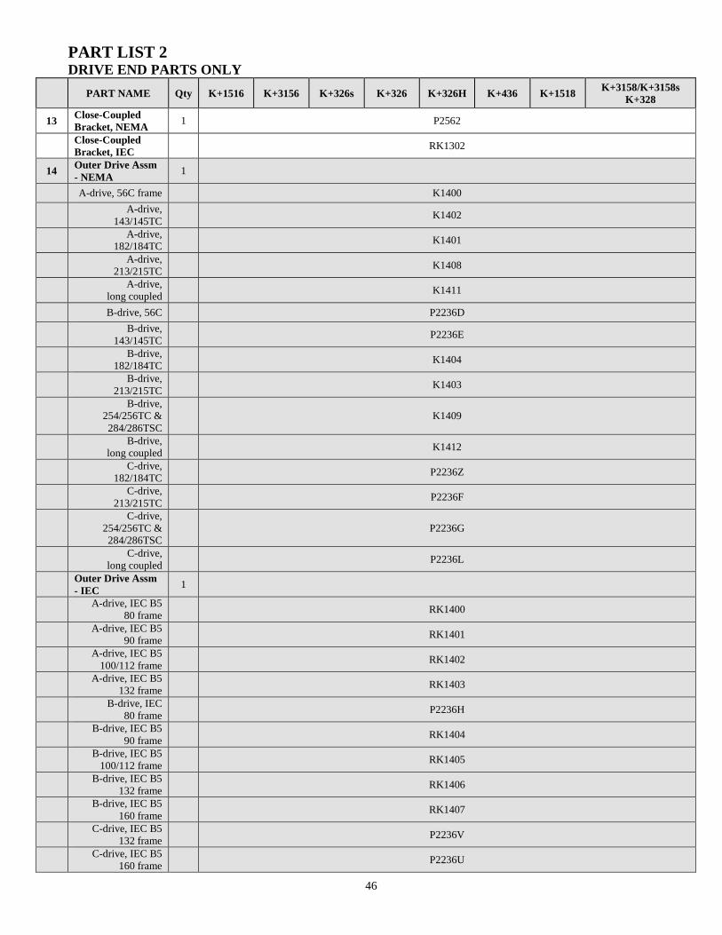
PART LIST 2DRIVE END PARTS ONLY
PART NAME Qty K+1516 K+3156 K+326s K+326 K+326H K+436 K+1518K+3158/K+3158s
K+328
13Close-CoupledBracket, NEMA
1 P2562
Close-CoupledBracket, IEC
RK1302
14Outer Drive Assm- NEMA
1
A-drive, 56C frame K1400
A-drive,143/145TC
K1402
A-drive,182/184TC
K1401
A-drive,213/215TC
K1408
A-drive,long coupled
K1411
B-drive, 56C P2236D
B-drive,143/145TC
P2236E
B-drive,182/184TC
K1404
B-drive,213/215TC
K1403
B-drive,254/256TC &284/286TSC
K1409
B-drive,long coupled
K1412
C-drive,182/184TC
P2236Z
C-drive,213/215TC
P2236F
C-drive,254/256TC &284/286TSC
P2236G
C-drive,long coupled
P2236L
Outer Drive Assm- IEC
1
A-drive, IEC B580 frame
RK1400
A-drive, IEC B590 frame
RK1401
A-drive, IEC B5100/112 frame
RK1402
A-drive, IEC B5132 frame
RK1403
B-drive, IEC80 frame
P2236H
B-drive, IEC B590 frame
RK1404
B-drive, IEC B5100/112 frame
RK1405
B-drive, IEC B5132 frame
RK1406
B-drive, IEC B5160 frame
RK1407
C-drive, IEC B5132 frame
P2236V
C-drive, IEC B5160 frame
P2236U
47
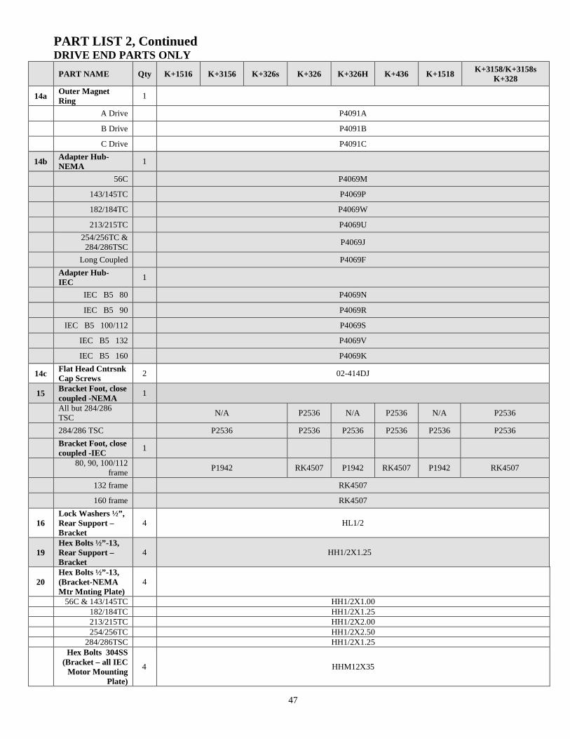
PART LIST 2, ContinuedDRIVE END PARTS ONLY
PART NAME Qty K+1516 K+3156 K+326s K+326 K+326H K+436 K+1518K+3158/K+3158s
K+328
14aOuter MagnetRing
1
A Drive P4091A
B Drive P4091B
C Drive P4091C
14bAdapter Hub-NEMA
1
56C P4069M
143/145TC P4069P
182/184TC P4069W
213/215TC P4069U
254/256TC &284/286TSC
P4069J
Long Coupled P4069F
Adapter Hub-IEC
1
IEC B5 80 P4069N
IEC B5 90 P4069R
IEC B5 100/112 P4069S
IEC B5 132 P4069V
IEC B5 160 P4069K
14cFlat Head CntrsnkCap Screws
2 02-414DJ
15Bracket Foot, closecoupled -NEMA
1
All but 284/286TSC
N/A P2536 N/A P2536 N/A P2536
284/286 TSC P2536 P2536 P2536 P2536 P2536 P2536
Bracket Foot, closecoupled -IEC
1
80, 90, 100/112frame
P1942 RK4507 P1942 RK4507 P1942 RK4507
132 frame RK4507
160 frame RK4507
16Lock Washers ½”,Rear Support –Bracket
4 HL1/2
19Hex Bolts ½”-13,Rear Support –Bracket
4 HH1/2X1.25
20Hex Bolts ½”-13,(Bracket-NEMAMtr Mnting Plate)
4
56C & 143/145TC HH1/2X1.00182/184TC HH1/2X1.25213/215TC HH1/2X2.00254/256TC HH1/2X2.50
284/286TSC HH1/2X1.25Hex Bolts 304SS
(Bracket – all IECMotor Mounting
Plate)
4 HHM12X35
48
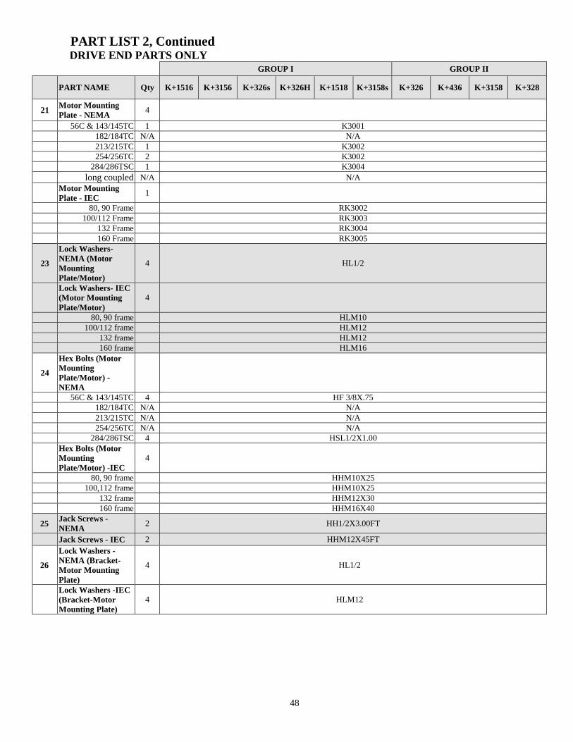
PART LIST 2, ContinuedDRIVE END PARTS ONLY
GROUP I GROUP II
PART NAME Qty K+1516 K+3156 K+326s K+326H K+1518 K+3158s K+326 K+436 K+3158 K+328
21Motor MountingPlate - NEMA
4
56C & 143/145TC 1 K3001182/184TC N/A N/A213/215TC 1 K3002254/256TC 2 K3002
284/286TSC 1 K3004
long coupled N/A N/A
Motor MountingPlate - IEC
1
80, 90 Frame RK3002100/112 Frame RK3003
132 Frame RK3004160 Frame RK3005
23
Lock Washers-NEMA (MotorMountingPlate/Motor)
4 HL1/2
Lock Washers- IEC(Motor MountingPlate/Motor)
4
80, 90 frame HLM10100/112 frame HLM12
132 frame HLM12160 frame HLM16
24
Hex Bolts (MotorMountingPlate/Motor) -NEMA
56C & 143/145TC 4 HF 3/8X.75182/184TC N/A N/A213/215TC N/A N/A254/256TC N/A N/A
284/286TSC 4 HSL1/2X1.00Hex Bolts (MotorMountingPlate/Motor) -IEC
4
80, 90 frame HHM10X25100,112 frame HHM10X25
132 frame HHM12X30160 frame HHM16X40
25Jack Screws -NEMA
2 HH1/2X3.00FT
Jack Screws - IEC 2 HHM12X45FT
26
Lock Washers -NEMA (Bracket-Motor MountingPlate)
4 HL1/2
Lock Washers -IEC(Bracket-MotorMounting Plate)
4 HLM12

49
PART LIST 2, ContinuedDRIVE END PARTS ONLY
GROUP I GROUP II
PART NAME Qty K+1516 K+3156 K+326s K+326H K+1518 K+3158s K+326 K+436 K+3158 K+328
27Hexbolts (Motor-Mtr Riser) -NEMA
284/286TSC N/A N/A N/A
56C & 143/145TC N/A N/A N/A
182/184TC 4 N/A HH3/8X1.25
213/215TC 4 N/A HH1/2X2.0
254/256TC 4 HH1/2X1.75 HH1/2X1.75
28Lock Washers S.S.(Motor – Mtr Riser)
56C & 143/145TC N/A N/A N/A
182/184TC N/A N/A N/A
213/215TC 4 N/A HL3/8
254/256TC 4 N/A HL1/2
284/286TSC 4
30Motor Risers, Close-Coupled
56C & 143/145TC(pair)
N/A N/A N/A
182/184TC (pair) N/A N/A N/A
213/215TC (pair) 1 N/A P2852
254/256TC (pair) 1 N/A P2815
Motor Risers, Long-Coupled
56C & 143/145TC(pair)
1/eaPN
K2103 K2103 & K2303
182/184TC (pair)1/eaPN
K2201 K2201 & K2303
213/215TC (pair) 1 N/A K2303
254/256TC (pair) 1 N/A K2302
33Pump Casing Riser -NEMA
56C & 143/145TC N/A N/A N/A
182/184TC N/A N/A N/A
213/215TC N/A N/A N/A
254/256TC 1 K2307 N/A
284/286TSC 1 K2306 N/A
Pump Case Riser -IEC
80, 90, 100/112 frame N/A N/A N/A
132 frame 1 HH1/2X1.5 N/A
160 frame 1 HH1/2X1.50 N/A
34 Foot Riser - NEMA
All but 254/256TC N/A N/A
254/256TC 1 K2307
Foot Riser (IEC)
80, 90, 100, 112Frame
1 RK5000 N/A
132, 160 Frame N/A N/A N/A
50
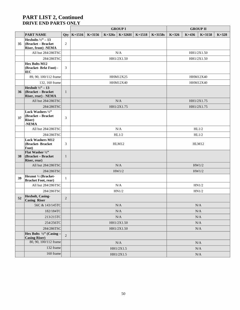
PART LIST 2, ContinuedDRIVE END PARTS ONLY
GROUP I GROUP II
PART NAME Qty K+1516 K+3156 K+326s K+326H K+1518 K+3158s K+326 K+436 K+3158 K+328
35Hexbolts ½” – 13(Bracket – BracketRiser, front) -NEMA
2
All but 284/286TSC N/A HH1/2X1.50
284/286TSC HH1/2X1.50 HH1/2X1.50
Hex Bolts M12(Bracket- Brkt Foot) -IEC
3
89, 90, 100/112 frame HHM12X25 HHM12X40
132, 160 frame HHM12X40 HHM12X40
36Hexbolt ½” – 13(Bracket – BracketRiser, rear) - NEMA
1
All but 284/286TSC N/A HH1/2X1.75
284/286TSC HH1/2X1.75 HH1/2X1.75
37
Lock Washers ½”(Bracket – BracketRiser)-NEMA
3
All but 284/286TSC N/A HL1/2
284/286TSC HL1/2 HL1/2
Lock Washers M12(Bracket- BracketFoot)
3 HLM12 HLM12
38Flat Washer ½”(Bracket – BracketRiser, rear)
1
All but 284/286TSC N/A HW1/2
284/286TSC HW1/2 HW1/2
39Hexnut ½ (Bracket-Bracket Foot, rear)
1
All but 284/286TSC N/A HN1/2
284/286TSC HN1/2 HN1/2
52Hexbolt, Casing-Casing Riser
2
56C & 143/145TC N/A N/A
182/184TC N/A N/A
213/215TC N/A N/A
254/256TC HH1/2X1.50 N/A
284/286TSC HH1/2X1.50 N/A
Hex Bolts ½” (Casing –Casing Riser)
2
80, 90, 100/112 frame N/A N/A
132 frame HH1/2X1.5 N/A
160 frame HH1/2X1.5 N/A
51
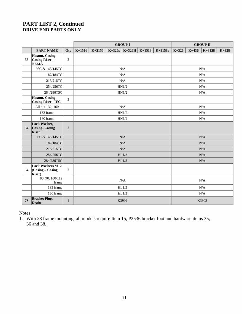
PART LIST 2, ContinuedDRIVE END PARTS ONLY
Notes:1. With 28 frame mounting, all models require Item 15, P2536 bracket foot and hardware items 35,
36 and 38.
GROUP I GROUP II
PART NAME Qty K+1516 K+3156 K+326s K+326H K+1518 K+3158s K+326 K+436 K+3158 K+328
53Hexnut, Casing-Casing Riser -NEMA
2
56C & 143/145TC N/A N/A
182/184TC N/A N/A
213/215TC N/A N/A
254/256TC HN1/2 N/A
284/286TSC HN1/2 N/A
Hexnut, Casing-Casing Riser - IEC
2
All but 132, 160 N/A N/A
132 frame HN1/2 N/A
160 frame HN1/2 N/A
54Lock Washer,Casing- CasingRiser
2
56C & 143/145TC N/A N/A
182/184TC N/A N/A
213/215TC N/A N/A
254/256TC HL1/2 N/A
284/286TSC HL1/2 N/A
54Lock Washers M12(Casing – CasingRiser)
2
80, 90, 100/112frame
N/A N/A
132 frame HL1/2 N/A
160 frame HL1/2 N/A
73Bracket Plug,Drain
1 K3902 K3902
52
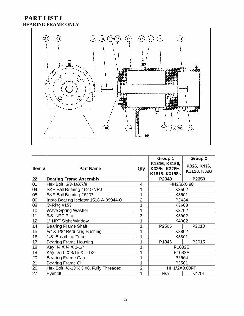
PART LIST 6BEARING FRAME ONLY
Item # Part Name Qty
Group 1 Group 2K1516, K3156,K326s, K326H,K1518, K3158s
K326, K436,K3158, K328
22 Bearing Frame Assembly P2349 P235001 Hex Bolt, 3/8-16X7/8 4 HH3/8X0.8804 SKF Ball Bearing #6207NRJ 1 K350205 SKF Ball Bearing #6207 1 K350106 Inpro Bearing Isolator 1518-A-09944-0 2 P243408 O-Ring #153 1 K360310 Wave Spring Washer 1 K370211 3/8” NPT Plug 3 K390212 1” NPT Sight Window 1 K400214 Bearing Frame Shaft 1 P2565 P201015 ¼” X 1/8” Reducing Bushing 1 K380216 1/8” Breathing Tube 1 K380117 Bearing Frame Housing 1 P1846 P201518 Key, ¼ X ¼ X 1-1/4 1 P1632E19 Key, 3/16 X 3/16 X 1-1/2 1 P1632A20 Bearing Frame Cap 1 P256421 Bearing Frame Oil 1 P250126 Hex Bolt, ½-13 X 3.00, Fully Threaded 2 HH1/2X3.00FT27 Eyebolt 1 N/A K4701
53
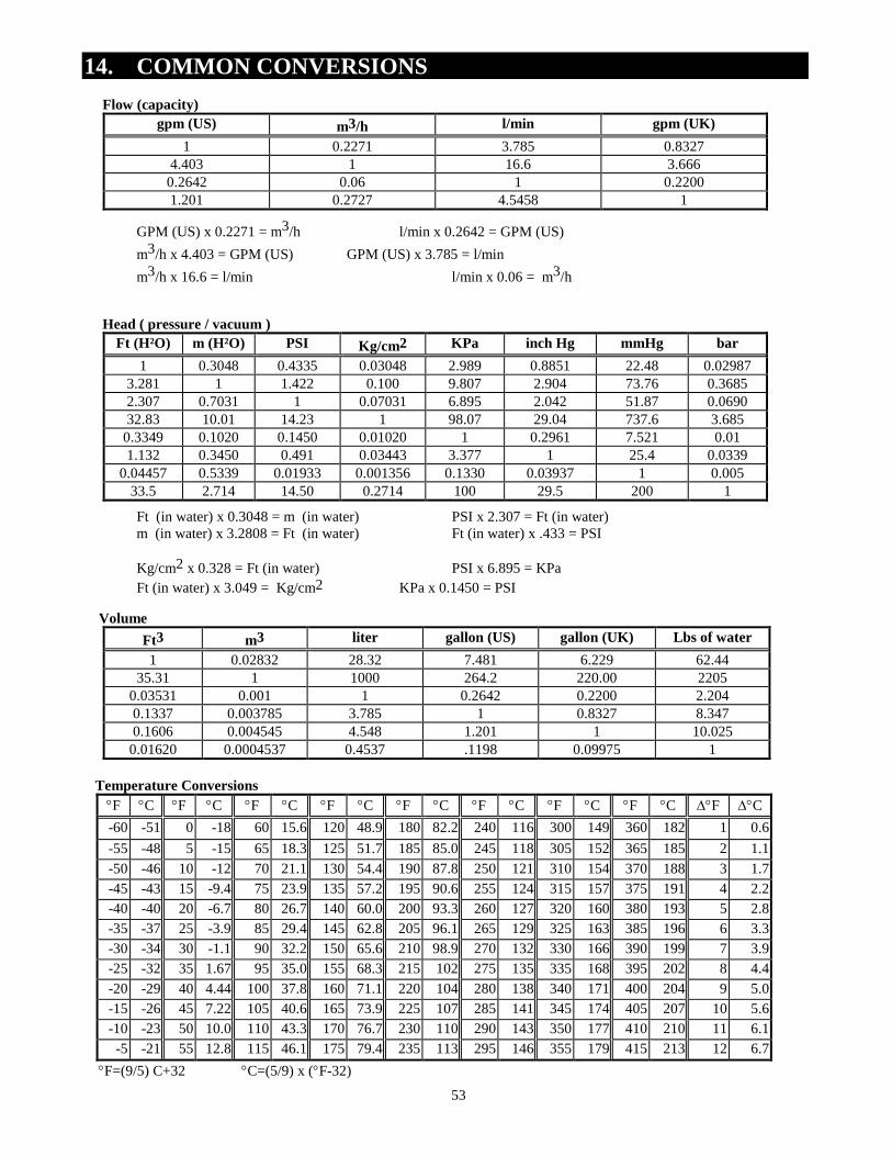
14. COMMON CONVERSIONS
Flow (capacity)
gpm (US) m3/h l/min gpm (UK)
1 0.2271 3.785 0.83274.403 1 16.6 3.6660.2642 0.06 1 0.22001.201 0.2727 4.5458 1
GPM (US) x 0.2271 = m3/h l/min x 0.2642 = GPM (US)
m3/h x 4.403 = GPM (US) GPM (US) x 3.785 = l/min
m3/h x 16.6 = l/min l/min x 0.06 = m3/h
Head ( pressure / vacuum )
Ft (H²O) m (H²O) PSI Kg/cm2 KPa inch Hg mmHg bar
1 0.3048 0.4335 0.03048 2.989 0.8851 22.48 0.029873.281 1 1.422 0.100 9.807 2.904 73.76 0.36852.307 0.7031 1 0.07031 6.895 2.042 51.87 0.069032.83 10.01 14.23 1 98.07 29.04 737.6 3.685
0.3349 0.1020 0.1450 0.01020 1 0.2961 7.521 0.011.132 0.3450 0.491 0.03443 3.377 1 25.4 0.0339
0.04457 0.5339 0.01933 0.001356 0.1330 0.03937 1 0.00533.5 2.714 14.50 0.2714 100 29.5 200 1
Ft (in water) x 0.3048 = m (in water) PSI x 2.307 = Ft (in water)m (in water) x 3.2808 = Ft (in water) Ft (in water) x .433 = PSI
Kg/cm2 x 0.328 = Ft (in water) PSI x 6.895 = KPa
Ft (in water) x 3.049 = Kg/cm2 KPa x 0.1450 = PSI
Volume
Ft3 m3 liter gallon (US) gallon (UK) Lbs of water
1 0.02832 28.32 7.481 6.229 62.4435.31 1 1000 264.2 220.00 2205
0.03531 0.001 1 0.2642 0.2200 2.2040.1337 0.003785 3.785 1 0.8327 8.3470.1606 0.004545 4.548 1.201 1 10.025
0.01620 0.0004537 0.4537 .1198 0.09975 1
Temperature Conversions
F C F C F C F C F C F C F C F C F C
-60 -51 0 -18 60 15.6 120 48.9 180 82.2 240 116 300 149 360 182 1 0.6
-55 -48 5 -15 65 18.3 125 51.7 185 85.0 245 118 305 152 365 185 2 1.1
-50 -46 10 -12 70 21.1 130 54.4 190 87.8 250 121 310 154 370 188 3 1.7
-45 -43 15 -9.4 75 23.9 135 57.2 195 90.6 255 124 315 157 375 191 4 2.2
-40 -40 20 -6.7 80 26.7 140 60.0 200 93.3 260 127 320 160 380 193 5 2.8
-35 -37 25 -3.9 85 29.4 145 62.8 205 96.1 265 129 325 163 385 196 6 3.3
-30 -34 30 -1.1 90 32.2 150 65.6 210 98.9 270 132 330 166 390 199 7 3.9
-25 -32 35 1.67 95 35.0 155 68.3 215 102 275 135 335 168 395 202 8 4.4
-20 -29 40 4.44 100 37.8 160 71.1 220 104 280 138 340 171 400 204 9 5.0
-15 -26 45 7.22 105 40.6 165 73.9 225 107 285 141 345 174 405 207 10 5.6
-10 -23 50 10.0 110 43.3 170 76.7 230 110 290 143 350 177 410 210 11 6.1
-5 -21 55 12.8 115 46.1 175 79.4 235 113 295 146 355 179 415 213 12 6.7
F=(9/5) C+32 C=(5/9) x (F-32)
54
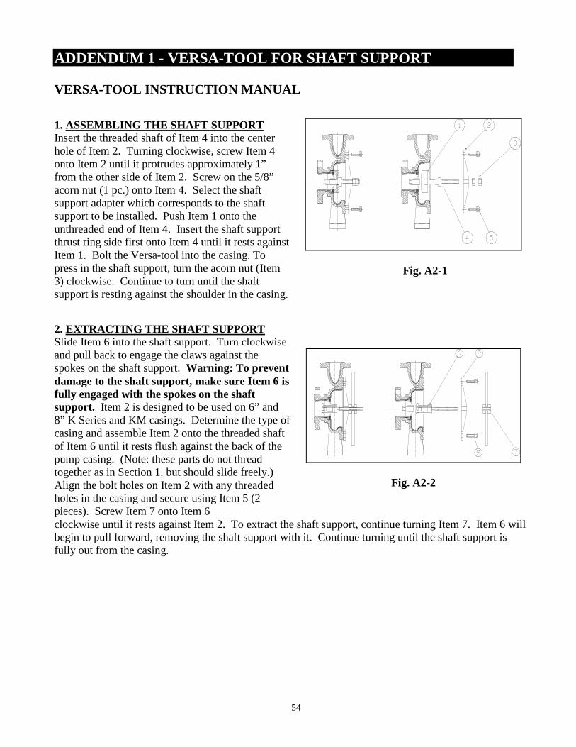
ADDENDUM 1 - VERSA-TOOL FOR SHAFT SUPPORT
VERSA-TOOL INSTRUCTION MANUAL
1. ASSEMBLING THE SHAFT SUPPORTInsert the threaded shaft of Item 4 into the centerhole of Item 2. Turning clockwise, screw Item 4onto Item 2 until it protrudes approximately 1”from the other side of Item 2. Screw on the 5/8”acorn nut (1 pc.) onto Item 4. Select the shaftsupport adapter which corresponds to the shaftsupport to be installed. Push Item 1 onto theunthreaded end of Item 4. Insert the shaft supportthrust ring side first onto Item 4 until it rests againstItem 1. Bolt the Versa-tool into the casing. Topress in the shaft support, turn the acorn nut (Item3) clockwise. Continue to turn until the shaftsupport is resting against the shoulder in the casing.
Fig. A2-1
2. EXTRACTING THE SHAFT SUPPORTSlide Item 6 into the shaft support. Turn clockwiseand pull back to engage the claws against thespokes on the shaft support. Warning: To preventdamage to the shaft support, make sure Item 6 isfully engaged with the spokes on the shaftsupport. Item 2 is designed to be used on 6” and8” K Series and KM casings. Determine the type ofcasing and assemble Item 2 onto the threaded shaftof Item 6 until it rests flush against the back of thepump casing. (Note: these parts do not threadtogether as in Section 1, but should slide freely.)Align the bolt holes on Item 2 with any threadedholes in the casing and secure using Item 5 (2pieces). Screw Item 7 onto Item 6
Fig. A2-2
clockwise until it rests against Item 2. To extract the shaft support, continue turning Item 7. Item 6 willbegin to pull forward, removing the shaft support with it. Continue turning until the shaft support isfully out from the casing.
55
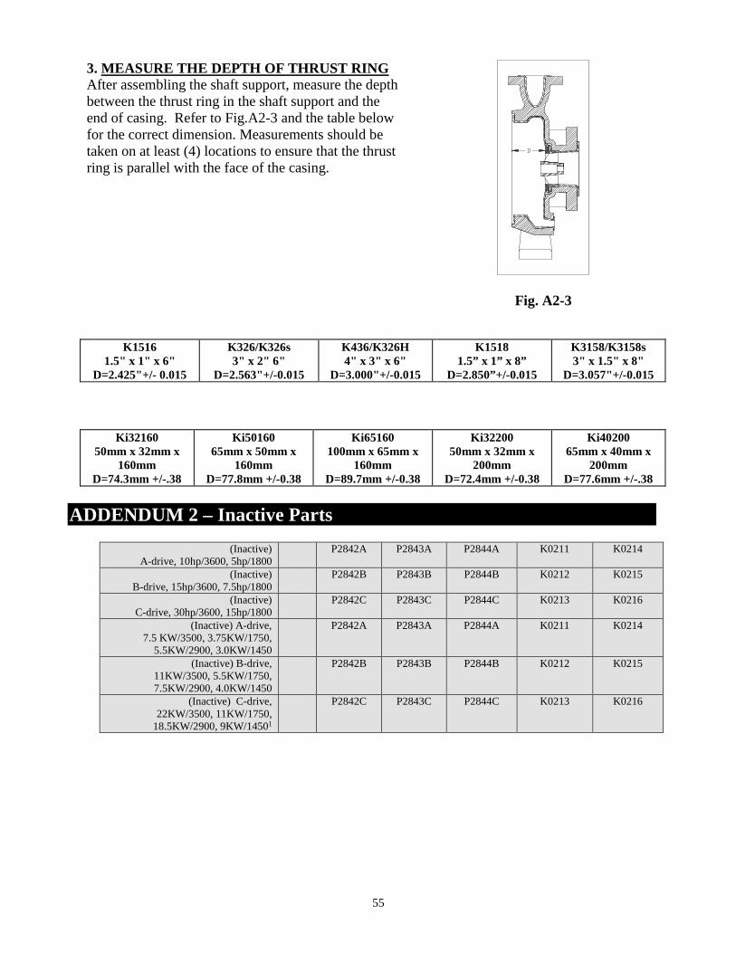
3. MEASURE THE DEPTH OF THRUST RINGAfter assembling the shaft support, measure the depthbetween the thrust ring in the shaft support and theend of casing. Refer to Fig.A2-3 and the table belowfor the correct dimension. Measurements should betaken on at least (4) locations to ensure that the thrustring is parallel with the face of the casing.
Fig. A2-3
K1516 K326/K326s K436/K326H K1518 K3158/K3158s1.5" x 1" x 6" 3" x 2" 6" 4" x 3" x 6" 1.5” x 1” x 8” 3" x 1.5" x 8"
D=2.425"+/- 0.015 D=2.563"+/-0.015 D=3.000"+/-0.015 D=2.850”+/-0.015 D=3.057"+/-0.015
Ki3216050mm x 32mm x
160mmD=74.3mm +/-.38
Ki5016065mm x 50mm x
160mmD=77.8mm +/-0.38
Ki65160100mm x 65mm x
160mmD=89.7mm +/-0.38
Ki3220050mm x 32mm x
200mmD=72.4mm +/-0.38
Ki4020065mm x 40mm x
200mmD=77.6mm +/-.38
ADDENDUM 2 – Inactive Parts
(Inactive)A-drive, 10hp/3600, 5hp/1800
P2842A P2843A P2844A K0211 K0214
(Inactive)B-drive, 15hp/3600, 7.5hp/1800
P2842B P2843B P2844B K0212 K0215
(Inactive)C-drive, 30hp/3600, 15hp/1800
P2842C P2843C P2844C K0213 K0216
(Inactive) A-drive,7.5 KW/3500, 3.75KW/1750,
5.5KW/2900, 3.0KW/1450
P2842A P2843A P2844A K0211 K0214
(Inactive) B-drive,11KW/3500, 5.5KW/1750,7.5KW/2900, 4.0KW/1450
P2842B P2843B P2844B K0212 K0215
(Inactive) C-drive,22KW/3500, 11KW/1750,
18.5KW/2900, 9KW/14501
P2842C P2843C P2844C K0213 K0216

ANSIMAG, 14845 W. 64th Avenue, Arvada, CO 80007, USAPhone: (303)425-0800 Fax: (303)425-0896
www.Sundyne.comK+ Installation, Operation, & Maintenance, September, 2015