installation & operation manual - floor heating & snow …€¦ ·...
TRANSCRIPT

Installation & Operation Manual
of56 ©203WattsRadiant
Snow Melting Control 654
FeaturesAutomaticSnow/IceDetectionSupportsBothInslab&RetrofitAerialSensorsManualStartWithTimerProgrammableScheduletekmarNet®CommunicationCompatibleWarmWeatherShutDownColdWeatherCutOutIdlingSnowMeltZoningWithPriorityTandemSnow/IceDetectionSlabProtectionStormEconoMeltManualOverrideSnowMeltZoneTrackingScenesAwayKeyExercisingAlertOutput
•••••••••••••••••••
IntroductionTheSnowMeltingControl654isdesignedtooperateelectricorhydronicequipmenttomeltsnoworicefromadriveway,loadingdock,sidewalk,patio,helipadorcarwashbay.Thesnowmeltsurfacetemperatureiscontrolledusingslaboutdoorresettoreduceoperatingenergycosts.The654providesautomaticstartandstopwhenusedwiththeSnow/IceSensor090.AutomaticstartwithatimedstopisavailablewhenusedwiththeSnowSensor095.The654canoperateadedicatedhydronicboileroramixingdevice.Isolationrelaysarerequiredtooperatelinevoltagepumps.ElectricsystemsrequireaseparateGFCIandelectricalrelaycontactor.

IOM-WR-Snow_Melting_Control-654328 2of56
ImportantSafetyInformation.............................................3Applications.......................................................................4
SingleZonewithBoiler.................................................. 4SingleZonewithBoiler&TandemSnow/IceSensors........6SingleZonewithModulatingSteamValve.................... 8Multi-ZoneCarWash.................................................... 0Multi-ZoneElectric........................................................ 2
Installation........................................................................4Preparation................................................................... 4PhysicalDimensions.................................................... 4InstallationLocation...................................................... 4Rough-InWiring............................................................ 4SizingtheTransformer................................................. 5ControlWiring............................................................... 5SensorWiring............................................................... 7TestingtheSensorWiring............................................ 8TestingtheControlWiring............................................ 8ManualOverride-MaximumHeat............................... 9ManualOverride-Test................................................. 9ManualOverride-Purge.............................................. 9ManualOverride-Off................................................... 9
SwitchSettings.................................................................9UserInterface...................................................................20
Display.......................................................................... 20OperationField............................................................. 20StatusField................................................................... 20Symbols........................................................................ 20
ProgrammableSettings....................................................2ProgrammingMenus.................................................... 2AccessLevelsandAccessLevelLock........................ 2ViewMenu.................................................................... 22SetTempMenu............................................................ 24TimeMenu.................................................................... 25ScheduleMenu............................................................ 26DisplayMenu................................................................ 27SceneMenu................................................................. 27MonitorMenu................................................................ 28ToolboxMenu............................................................... 29OverrideMenu.............................................................. 30SystemMenu................................................................ 3BoilerMenu.................................................................. 32MixMenu...................................................................... 33tekmarNet®Menu......................................................... 34
SequenceofOperation................................................... 35SnowMeltingOverview................................................ 35SlabTemperatureControl............................................ 35MeltOperation.............................................................. 35Melt-ManualStartandTimedStop............................ 36Melt-AutomaticStartandStop................................... 36Melt-EconoMelt........................................................... 37Melt-AutomaticStartandTimedStop........................ 37Melt-TrackedStartandStop...................................... 38Melt-ScheduledStartandStop.................................. 38AdditionalMeltingTime................................................ 39IdleOperation............................................................... 39StormOperation........................................................... 39WarmWeatherShutDown........................................... 40ColdWeatherCutOut.................................................. 40AwayScene.................................................................. 40ProgrammableSchedules............................................ 4TimeClock.................................................................... 4SnowMeltZonesandPriority...................................... 4SlabProtection............................................................. 43ApplicationModes........................................................ 43ElectricOperation......................................................... 43PulseWidthModulationOperation.............................. 43BoilerOperation........................................................... 43MixingOperation.......................................................... 45PipingofVariableSpeedInjectionSystems................ 46DesignProcedure......................................................... 47TandemSnow/IceDetection...................................... 48Exercising..................................................................... 48AlertRelay.................................................................... 48PumpPostPurge.......................................................... 48MeltandStormGroups................................................ 49UserSwitchSetup........................................................ 49
Troubleshooting................................................................50ErrorMessages............................................................ 50FrequentlyAskedQuestions........................................ 54
JobRecord...................................................................... 54TechnicalData..................................................................56HydronicSystemElectronicControlsandThermostatsLimitedWarranty..............................................................56
CongratulationsonthepurchaseofyournewSnowMeltingControl!Thismanualcoversthecompleteinstallation,programmingandsequenceofoperationforthiscontrol.Youwillalsofindinstructionontesting,commissioning,andtroubleshootingthecontrolandsystemthatitoperates.
Getting Started
Table of Contents

3of56 ©203WattsRadiant
Theinstallermustensurethatthiscontrolanditswiringareisolatedand/orshieldedfromstrongsourcesofelectromagneticnoise.Conversely,thisClassBdigitalapparatuscomplieswithPart5oftheFCCRulesandmeetsallrequirementsoftheCanadianInterference-CausingEquipmentRegulations.However,ifthiscontroldoescauseharmfulinterferencetoradioortelevisionreception,whichisdeterminedbyturningthecontroloffandon,theuserisencouragedtotrytocorrect
theinterferencebyre-orientatingorrelocatingthereceivingantenna,relocatingthereceiverwithrespecttothiscontrol,and/orconnectingthecontroltoadifferentcircuitfromthattowhichthereceiverisconnected.CetappareilnumériquedelaclasseBrespectetouteslesexigencesduRèglementsurlematérielbrouilleurduCanada.
To avoid serious personal injury and damage to the equipment:
Improperinstallationandoperationofthiscontrolcouldresultindamagetotheequipmentandpossiblyevenpersonalinjuryordeath.Thiselectroniccontrolisnotintendedforuseasaprimarylimitcontrol.Othercontrolsthatareintendedandcertifiedassafetylimitsmustbeplacedintothecontrolcircuit.Donotattempttoservicethecontrol.Therearenouserserviceablepartsinsidethecontrol.Attemptingtodosovoidswarranty.
•
•
•
Important Safety Information
Itistheinstallersresponsibilitytoensurethatthiscontrolissafelyinstalledaccordingtoallapplicablecodesandstandards.WattsRadiantisnotresponsiblefordamagesresultingfromimproperinstallationand/ormaintenance.
ReadManualandallproductlabelsBEFOREusingtheequipment.Donotuseunlessyouknowthesafeandproperoperationofthisequipment.KeepthisManualavailableforeasyaccessbyallusers.ReplacementManualsareavailableatWattsRadiant.com
•
•
•
Disconnectallpowerbeforeopeningthecontrol.
•
Radio Frequency Interference

IOM-WR-Snow_Melting_Control-654328 4of56
OptionSnow/IceSensor090
Option2SnowSensor095andSlabSensor072
Option3SlabSensor072
OutdoorSensor070
Relay Relay
BoilerSupplySensor
082
SystemPump
ModulatingBoiler
654
DescriptionASnowMeltingControl654operatesahydronicsnowmeltingsystemusingamodulatingboilerandasystempump.Theboilerispipedinprimary-secondarytothesnowmeltsystemtoallowthesystempumptooperatecontinuouslyduringmeltingoridlingwhileallowingtheboilerandboilerpumptoturnonandoffasrequired.Theboilerfiringrateismodulatedusinga0-0V(dc)or4-20mAsignal.Theslabisheatedtomaintaintheslabtargettemperature.WhenaSnow/IceSensor090isinstalled,thesystemautomaticallystartswhensnoworiceisdetectedandcontinuestorununtiltheslabisdry.WhenaSnowSensor095isinstalledtogetherwithaSlabSensor072,thesystemautomaticallystartswhensnowisdetectedandrunsonatimerbeforeshuttingoff.AllsystemscanbemanuallystartedandshutoffusingatimerwheneitheraSnow/IceSensor090oraSlabSensor072isinstalled.
Application SettingsSetting Name Value
APPMODE BOIL
BOILTYPE MOD(modulatingboiler)
AUXRELAY SYS(systempump)
Snow or Ice DetectorOption Start and Stop Sequence Sensors Required (sold separately)
Autostart/Autostop Snow/IceSensor090
2 Autostart/Timedstop SnowSensor095&SlabSensor072
3 Manualstart/Timedstop SlabSensor072
Single Zone with Boiler A654-1 Mechanical
Applications

5of56 ©203WattsRadiant
Snow/IceSensor090
OutdoorSensor
070
SupplySensor
082
Relay
SystemPump
Relay
OptionaltN4
Communication
SnowSensor095
SlabSensor072
SlabBrn
SlabBrn
ComBlkYel Blu Red
ComBlkYel Blu Red
Or And/Or
2187
3456
2187
3456
C tN4
ModulatingBoiler
T T–+
Transformer
LN C
R
SnowSensor
095
SlabBrn
+ModtN4Aux Ht R C
BretOut/
Com–BlkYel Blu Red Sup
No Power
LNG5V(ac)
Single Zone with Boiler A654-1 Electrical

IOM-WR-Snow_Melting_Control-654328 6of56
DescriptionAsinglezoneincludestwoSnow/IceSensors090forTandemSnow/IceDetectionforawidersnoworicedetectionareaandbackupshouldoneofthetwosensorsfail.Whensnoworiceisdetectedthesnowmeltingsystemisautomaticallystartedandstopswhentheslabisdry.EachsensorrequiresaSnowMeltingControl654.ThemasterSnowMeltingControl654operatesahydronicsnowmeltingsystemusingamodulatingboilerandasystempump.Theboilerispipedinprimary-secondarytothesnowmeltsystemtoallowthesystempumptooperatecontinuouslyduringmeltingoridlingwhileallowingtheboilerandboilerpumptoturnonandoffasrequired.Theboilerfiringrateismodulatedusinga0-0V(dc)or4-20mAsignal.ThememberSnowMeltingControlmonitorstheSnow/IceSensorandrelaysthesensorinformationtothemastercontrolusingtekmarNet®communication.
OutdoorSensor070
Relay Relay
BoilerSupplySensor
082
SystemPump
ModulatingBoiler
Snow/IceSensor090
654Master
654Member
Snow/IceSensor090
654 Master - Application SettingsSetting Name Value
APPMODE BOIL
BOILTYPE MOD(modulatingboiler)
AUXRELAY SYS(systempump)
Snow or Ice DetectorOption Start and Stop Sequence Sensors Required (sold separately)
Autostart/Autostop Snow/IceSensor090
654 Member - Application SettingsSetting Name Value
APPMODE 090
Single Zone with Boiler and Tandem Snow / Ice Sensors A654-2 Mechanical

7of56 ©203WattsRadiant
LNG
OutdoorSensor
070
SupplySensor
082
5V(ac)
Relay
SystemPump
Relay2187
3456
2187
3456
ModulatingBoiler
T T–+
Transformer
LN C
R
Snow/IceSensor090
654Member
654Master
Snow/IceSensor090
SlabBrn
+ModtN4Aux Ht R C
BretOut/
Com–BlkYel Blu Red Sup
No Power
SlabBrn
+ModtN4Aux Ht R C
BretOut/
Com–BlkYel Blu Red Sup
No Power
Single Zone with Boiler and Tandem Snow / Ice Sensors A654-2 Electrical

IOM-WR-Snow_Melting_Control-654328 8of56
DescriptionASnowMeltingControl654operatesamodulatingsteamvalveandasystempump.Theheatsourcemaybeeitherdistrictsteamorasteamboiler.Theslabtemperatureiscontrolledbyadjustingthesteamvalvepositionusingananalog0to0V(dc)or4to20mAsignal.Theslabisheatedtomaintaintheslabtargettemperature.WhenaSnow/IceSensor090isinstalled,thesystemautomaticallystartswhensnoworiceisdetectedandcontinuestorununtiltheslabisdry.WhenaSnowSensor095isinstalledtogetherwithaSlabSensor072,thesystemautomaticallystartswhensnowisdetectedandrunsonatimerbeforeshuttingoff.AllsystemscanbemanuallystartedandshutoffusingatimerwheneitheraSnow/IceSensor090oraSlabSensor072isinstalled.
Snow or Ice DetectorOption Start and Stop Sequence Sensors Required (sold separately)
Autostart/Autostop Snow/IceSensor090
2 Autostart/Timedstop SnowSensor095&SlabSensor072
3 Manualstart/Timedstop SlabSensor072
Application SettingsSetting Name Value
APPMODE MIX
BOILTYPE OFF
AUXRELAY SYS(systempump)
OutdoorSensor070
Relay
MixSupplySensor
082
DistrictSteam
SystemPump
ModulatingSteamValve
654
OptionSnow/IceSensor090
Option2SnowSensor095andSlabSensor072
Option3SlabSensor072
Single Zone with Modulating Steam Valve A654-3 Mechanical

9of56 ©203WattsRadiant
LNG5V(ac)
Snow/IceSensor090
OutdoorSensor
070
SupplySensor
082
Relay
OptionaltN4
Communication
SnowSensor095
SlabSensor072
SlabBrn
SlabBrn
ComBlkYel Blu Red
ComBlkYel Blu Red
Or And/Or
2187
3456
SnowSensor
095
SlabBrn
+ModtN4Aux Ht R C
BretOut/
Com–BlkYel Blu Red Sup
No Power
ModulatingSteamValve
SystemPump
–+
CtN4
Transformer
LN R
C
Single Zone with Modulating Steam Valve A654-3 Electrical

IOM-WR-Snow_Melting_Control-654328 0of56
DescriptionAcarwashcanhaveupto2baysandapronseachhavinganicemeltingsystemoperatedbyaSnowMeltingControl654.Aboilerorwaterheaterheatsastoragetankwhichisusedforhotwatertowashvehiclesandheattheicemeltingsystem.ThecontrolusesaSlabSensor072tomeasuretheslabtemperatureandoperatesthezonetoensuretheslabisabovefreezing.Aprogrammablescheduleisusedtooperatetheicemeltingsystemduringthecarwashbusinesshoursandshutsoffthesystemwhenthecarwashisclosed.
Zone 1 - Application SettingsSetting Name Value
APPMODE PWM
BOILTYPE OFF
AUXRELAY SYS(systempump)
OUT/BRET OUT
Zone 2 - Application SettingsSetting Name Value
APPMODE PWM
BOILTYPE OFF
AUXRELAY SYS(systempump)
OUT/BRET OFF
Multi-Zone Car Wash A654-4 Mechanical
OutdoorSensor
070
FreezeProtectionAquastat
Zone2Pump
Boiler
SystemPump
SlabSensor072
ZonePump
Relay
Zone
Zone2
654
654
SlabSensor072
Relay
Relay
SupplySensor082
SupplySensor082

of56 ©203WattsRadiant
OutdoorSensor
070
FreezeProtectionAquastat
ZonePump
Relay
Transformer
L
N5V(ac)
Relay Relay
Zone2Pump
SystemPump
SupplySensor
082
Zone Zone2
SupplySensor
082
SlabSensor
072
SlabSensor
072
C R
SlabBrn
+ModtN4Aux Ht R C
BretOut/
Com–BlkYel Blu Red Sup
No Power
SlabBrn
+ModtN4Aux Ht R C
BretOut/
Com–BlkYel Blu Red Sup
No Power
2187
3456
2187
3456
2187
3456
Multi-Zone Car Wash A654-4 Electrical

IOM-WR-Snow_Melting_Control-654328 2of56
DescriptionAnelectricsnowmeltingsystemhasupto2zones.Zonehaspriorityoverzones2through2.EachSnowMeltingControl654isconnectedtoanelectricalcontactorwhichinturnenergizestheelectriccables.Wheneverthezoneelectricalcontactorisshutoff,zone2isabletooperate.Eachslabisheatedtomaintainitsslabtargettemperature.WhenaSnow/IceSensor090isinstalled,thesystemautomaticallystartswhensnoworiceisdetectedandcontinuestorununtiltheslabisdry.WhenaSnowSensor095isinstalledtogetherwithaSlabSensor072,thesystemautomaticallystartswhensnowisdetectedandrunsonatimerbeforeshuttingoff.AllsystemscanbemanuallystartedandshutoffusingatimerwheneitheraSnow/IceSensor090oraSlabSensor072isinstalled.
Zone 1 - Application SettingsSetting Name Value
APPMODE ELEC
OUT/BRET OUT
PRIORITY COND(conditional)
Zone 2 - Application SettingsSetting Name Value
APPMODE ELEC
OUT/BRET OFF
PRIORITY COND(conditional)
Snow or Ice DetectorOption Start and Stop Sequence Sensors Required (sold separately)
Autostart/Autostop Snow/IceSensor090
2 Autostart/Timedstop SnowSensor095&SlabSensor072
3 Manualstart/Timedstop SlabSensor072
OutdoorSensor070
ElectricalPowerSupply
Zone
Zone2
654
654
OptionSnow/IceSensor090
Option2SnowSensor095andSlabSensor072
Option3SlabSensor072
AlertEquipment
AlertEquipment
OptionSnow/IceSensor090
Option2SnowSensor095andSlabSensor072
Option3SlabSensor072
Multi-Zone Electric A654-5 Mechanical
ProMeltContactorProPanel
ElectricalPowerSupply
ProMeltContactorProPanel

3of56 ©203WattsRadiant
Snow/IceSensor090
OutdoorSensor
070
Zone
Zone2
ProMeltContactorProPanel
CP-50CP-00CP-200
ProMeltContactorProPanel
CP-50CP-00CP-200
OptionalAlert
Equipment
OptionalAlert
Equipment
SnowSensor095
SlabSensor072
Snow/IceSensor090
SnowSensor095
SlabSensor072
SlabBrn
SlabBrn
ComBlkYel Blu Red
ComBlkYel Blu Red
Or And/Or
24V C PM
SlabBrn
SlabBrn
ComBlkYel Blu Red
ComBlkYel Blu Red
Or And/Or
24V C PM
SnowSensor
095
SlabBrn
+ModtN4Aux Ht R C
BretOut/
Com–BlkYel Blu Red Sup
No Power
SlabBrn
+ModtN4Aux Ht R C
BretOut/
Com–BlkYel Blu Red Sup
No Power
SnowSensor
095
Multi-Zone Electric A654-5 Electrical

IOM-WR-Snow_Melting_Control-654328 4of56
Tools Required-----------------------------------------------------------------------------------------JewellerscrewdriverPhillipsheadscrewdriver
••
Needle-nosePliersWireStripper
••
Materials Required-------------------------------------------------------------------------------------8AWGLVTSolidWire(LowVoltageConnections)• 24V(ac)Transformer•
Whenchoosingthelocationforthecontrol,considerthefollowing:
InteriorWall.Keepdry.Avoidpotentialleakageontothecontrol.RelativeHumiditylessthan90%.Non-condensingenvironment.Noexposuretoextremetemperaturesbeyond-4to22°F(-20to50°C).Nodraft,directsun,orothercauseforinaccuratetemperaturereadings.
•••
•
•
Awayfromequipment,appliances,orothersourcesofelectricalinterference.Easyaccessforwiring,viewing,andadjustingthedisplayscreen.Approximately5feet(.5m)offthefinishedfloor.Themaximumlengthofwireis500feet(50m).Stripwireto3/8"(0mm)forallterminalconnections.Usestandard8conductor,8AWGwire.
•
•
••••
Low Voltage Wiring-------------------------------------------------------------------------------------Eachcablemustbepulledfromtheequipmenttothecontrol’splasticenclosure.Alllowvoltagewiringconnectionsentertheenclosurethroughthesquareknockoutontherear.Itisrecommendedtolabeleachcableforeasyidentification.Alllowvoltagewiresaretobestrippedtoalengthof3/8"(9mm)toensureproperconnectiontothecontrol.Pull four conductor 18 AWG LVT cable, up to 500 feet (150 m) for the following equipment:
SnowSensor095Pull five conductor 18 AWG LVT cable, up to 500 feet (150 m) for the following equipment:
Snow/IceSensor090
•
•
Pull two conductor 18 AWG LVT cable, up to 500 feet (150 m) for the following equipment:
24V(ac)powerfromtransformerOutdoortemperaturesensorSupplysensor(ifapplicable)On/offboiler(ifapplicable)Modulatingboiler0-0V(dc)or4-20mA(ifapplicable)Mixingvalveormixinginjectionpump0-0V(dc)or4-20mA(ifapplicable)Boilerreturntemperaturesensor(ifapplicable)Alertoutput(ifapplicable)tekmarNet®4communicationtootherdevicesSlabsensor072(ifapplicable)
••••••
••••
FrontView
5"(127 mm)
3-1/4"(82 mm)
SideView
15/16" (23 mm)
MountingBase
654
SlabBrn
+ModtN4Aux Ht R C
BretOut/
ComComBlkYel Blu Red Sup
No Power
1-1/2"(38 mm)
9/16" (14 mm)
CL1-7/8" (47 mm)
3/4" (19 mm)
CL
CL
13/16" (20 mm)
4" (102 mm)
2-1/2"(64 mm)
29/32"(23 mm)
3-1/4" (83 mm)
InstallationPreparation
Physical Dimensions
Installation Location
Rough-In Wiring

5of56 ©203WattsRadiant
Snow/IceSensor090
SlabBrn
+ModtN4Aux Ht R C
BretOut/
Com–BlkYel Blu Red Sup
No Power
SnowSensor095
SlabSensor072
SlabBrn
+ModtN4Aux Ht R C
BretOut/
Com–BlkYel Blu Red Sup
No Power
SnowSensor
095
Thecontrolrequiresanexternaltransformer.Thetotalpowercapacityofthepowersupplyshouldbelargerthanthetotalloadofallthedevicesconnectedtothecontrol.Thistotalloadmustnotexceed00VA.
Snow / Ice Sensor----------------------------------- Snow and Slab Sensor------------------------------
Outdoor, Supply and Boiler Return Sensor----------
OutdoorSensor
070or
BoilerReturnSensor
082
SupplySensor
082
SlabBrn
+ModtN4Aux Ht R C
BretOut/
Com–BlkYel Blu Red Sup
No Power
Modulating Output and tN4 Communication---------
ModulatingBoilerMixingValveor
MixingInjectionPump0-0V(dc)Signal
tekmarNet®4Communication
– +
tN4 CSlabBrn
+ModtN4Aux Ht R C
BretOut/
Com–BlkYel Blu Red Sup
No Power
Sizing the Transformer
Control Wiring
(ifapplicable)

IOM-WR-Snow_Melting_Control-654328 6of56
Transformer and Relays----------------------------------------------------------------------------------------
Alert Relay Output---------------------------------------------------------------------------------------------
AlertEquipment
SlabBrn
+ModtN4Aux Ht R C
BretOut/
Com–BlkYel Blu Red Sup
No Power
Relay
SystemPump
Relay2187
3456
2187
3456
Transformer
LN C
R
On/OffBoiler
TT
SlabBrn
+ModtN4Aux Ht R C
BretOut/
Com–BlkYel Blu Red Sup
No Power
LNG5V(ac)

7of56 ©203WattsRadiant
Thetemperaturesensor(thermistor)isbuiltintothesensorenclosure.
Removethescrewandpullthefrontcoveroffthesensorenclosure.Theoutdoorsensorcaneitherbemounteddirectlyontoawallora2"x4"electricalbox.Whentheoutdoorsensoriswallmounted,thewiringshouldenterthroughthebackorbottomoftheenclosure.Donotmounttheoutdoorsensorwiththeconduitknockoutfacingupwardsasraincouldentertheenclosureanddamagethesensor.Inordertopreventheattransmittedthroughthewallfrom
•
•
•
affectingthesensorreading,itmaybenecessarytoinstallaninsulatingbarrierbehindtheenclosure.Theoutdoorsensorshouldbemountedonawallwhichbestrepresentstheheatloadonthebuilding(anorthernwallformostbuildingsandasouthernfacingwallforbuildingswithlargesouthfacingglassareas).Theoutdoorsensorshouldnotbeexposedtoheatsourcessuchasventilationorwindowopenings.Theoutdoorsensorshouldbeinstalledatanelevationabovethegroundthatwillpreventaccidentaldamageortampering.
•
•
Mounting the Outdoor Sensor----------------------------------------------------------------------------------
Sensorwithbottomentrywiring
Sensorwithrearentrywiring
Sensormountedonto2"x4"electricalbox
Connect8AWGorsimilarwiretothetwoterminalsprovidedintheenclosureandrunthewiresfromtheoutdoorsensortothecontrol.Donotrunthewiresparalleltotelephoneorpowercables.Ifthesensorwiresarelocatedinanareawithstrongsourcesofelectromagneticinterference(EMI),shieldedcableortwistedpairshouldbeusedorthewirescanberuninagroundedmetalconduit.Ifusingshieldedcable,theshieldwireshouldbeconnectedtotheComterminalonthecontrolandnottoearthground.Followthesensortestinginstructionsinthisbrochureandconnectthewirestothecontrol.Replacethefrontcoverofthesensorenclosure.
•
•
•
Wiring the Outdoor Sensor-------------------------------------------------------------------------------------
Wires from outdoorsensor to control’soutdoor sensor andsensor commonterminals
Sensor is built intothe enclosure
Mounting the Universal Sensor---------------------------------------------------------------------------------
Sensor Wiring
Thesesensorsaredesignedtomountonapipeorinatemperatureimmersionwell.TheUniversalSensorshouldbeplaceddownstreamofapumporafteranelboworsimilarfitting.Thisisespeciallyimportantiflargediameterpipesareusedasthethermalstratificationwithinthepipecanresultinerroneoussensorreadings.Propersensorlocationrequiresthatthefluidisthoroughlymixedwithinthepipebeforeitreachesthesensor.
Strapped to PipeTheUniversalSensorcanbestrappeddirectlytothepipeusingthecabletieprovided.Insulationshouldbeplacedaroundthesensortoreducetheeffectofaircurrentsonthesensormeasurement.

IOM-WR-Snow_Melting_Control-654328 8of56
Agoodqualitytestmetercapableofmeasuringupto5,000kΩ(kΩ=000Ω)isrequiredtomeasurethesensorresistance.Inadditiontothis,theactualtemperaturemustbemeasuredwitheitheragoodqualitydigitalthermometer,orifathermometerisnotavailable,asecondsensorcanbeplacedalongsidetheonetobetestedandthereadingscompared.Firstmeasurethetemperatureusingthethermometerandthenmeasuretheresistanceofthesensoratthecontrol.Thewiresfromthesensormustnotbeconnectedtothecontrolwhilethetestisperformed.Usingthechartbelow,estimatethetemperaturemeasuredbythesensor.Thesensorand
thermometerreadingsshouldbeclose.Ifthetestmeterreadsaveryhighresistance,theremaybeabrokenwire,apoorwiringconnectionoradefectivesensor.Iftheresistanceisverylow,thewiringmaybeshorted,theremaybemoistureinthesensororthesensormaybedefective.Totestforadefectivesensor,measuretheresistancedirectlyatthesensorlocation.
Temperature Resistance Temperature Resistance Temperature Resistance Temperature Resistance°F °C °F °C °F °C °F °C-50 -46 490,83 20 -7 46,28 90 32 7,334 60 7 ,689-45 -43 405,70 25 -4 39,93 95 35 6,532 65 74 ,538-40 -40 336,606 30 - 34,558 00 38 5,828 70 77 ,403-35 -37 280,279 35 2 29,996 05 4 5,20 75 79 ,28-30 -34 234,96 40 4 26,099 0 43 4,665 80 82 ,72-25 -32 96,358 45 7 22,763 5 46 4,84 85 85 ,073-20 -29 65,80 50 0 9,900 20 49 3,760 90 88 983-5 -26 39,403 55 3 7,436 25 52 3,383 95 9 903-0 -23 8,08 60 6 5,3 30 54 3,050 200 93 829-5 -2 00,22 65 8 3,474 35 57 2,754 205 96 7630 -8 85,362 70 2 ,883 40 60 2,490 20 99 7035 -5 72,98 75 24 0,50 45 63 2,255 25 02 6480 -2 62,465 80 27 9,299 50 66 2,045 220 04 5985 -9 53,658 85 29 8,250 55 68 ,857 225 07 553
SensorWell
UniversalSensor
Immersion WellIfaUniversalSensorismountedonto"(25mm)diameterLtypecopperpipe,thereisapproximatelyan8seconddelaybetweenasuddenchangeinwatertemperatureandthetimethesensormeasuresthetemperaturechange.Thisdelayincreasesconsiderablywhenmildsteel(blackiron)pipeisused.Ingeneral,itisrecommendedthatatemperaturewellbeusedforsteelpipeofdiametergreaterthan-/4"(32mm).Temperaturewellsarealsorecommendedwhenlargediameterpipesareusedandfluidstratificationispresent.
Testing the Power---------------------------------------------------------------------------------------------. Removethefrontcoverfromthecontrol.2. Useanelectricaltestmetertomeasure(ac)voltagebetweentheRandCterminals.Thereadingshouldbe24V(ac)
+/–0%.3. Installthefrontcover.
Testing the Relay Outputs---------------------------ThecontrolincludesanOverridemenutocheckifthecontrol’srelaysareoperatingandthatthecontroliswiredcorrectlytothesnowmeltingequipment.Step: PressandholdtheHomebuttonfor3seconds.Step2: PressNEXTtonavigatetotheOverridemenu.Step3: PressENTERtoentertheOverridemenu.Step4: SelectManualOverridetoHand.Step5: Forhydronicsystems,setSystemPumptoOn.The
systempumpshouldnowbeoperating.
Step6: SetHeatRelaytoOn.Theboilerorelectricheatingcablesshouldstartheating.
Step7: FormodulatingboilerschangetheBoilerPercentfrom0to00%.Theboilershouldbefiring.
Step8: Foramixingvalveormixinginjectionpump,changetheMixPercentfrom0to00%.Themixingvalveshouldopenorthemixinginjectionpumpshouldincreasespeed.
Step9: SelecttheOverrideTimeafterwhichthecontrolresumesnormaloperation.
Step0:ExittheManualOverridebyselectingAuto.
Testing the Sensor Wiring
Testing the Control Wiring
Do not apply voltage to a sensor at any time as damage to the sensor may result.

9of56 ©203WattsRadiant
Inhydronicapplicationmodes, thecontrol includesaMaximumHeatoperationwherethecontroloperatesthesnowmeltingsystemtomaintainthemaximumallowedheatingsetpoints.Thisallowstestingofthesnowmeltingsystemduringwarmweather.
Step: PressandholdtheHomebuttonfor3seconds.Step2: PressNEXTtonavigatetotheOverridemenu.Step3: PressENTERtoentertheOverridemenu.Step4: SelectManualOverridetoMax.Step5: SelecttheMaximumHeatTimeafterwhichthecontrol
resumesnormaloperation.Step6: ExittheManualOverridebyselectingAuto.
Whenoperatingahydronicsnowmeltingsystem,itisnecessarytopurgeandbleedallairoutofthesystem.ThecontrolincludesaPurgeoperationwheretheSystemPumpaswellaspumpsoperatedbythetekmarNet®systemareallturnedontoassistinpurgingairfromthesystem.
Step: PressandholdtheHomebuttonfor3seconds.Step2: PressNEXTtonavigatetotheOverridemenu.Step3: PressENTERtoentertheOverridemenu.Step4: SelectManualOverridetoPurge.Step5: SelecttheMaximumPurgeTimeafterwhichthecontrol
resumesnormaloperation.Step6: ExittheManualOverridebyselectingAuto.
ThesnowmeltingsystemcanbemanuallyturnedoffandthecontrolremainsoffuntilmanuallychangedbacktoAuto.Thisallowstheinstallerorendusertopermanentlydisablethesnowmeltingsystemwithoutremovingpowerfromthecontrol.
Step: PressandholdtheHomebuttonfor3seconds.Step2: PressNEXTtonavigatetotheOverridemenu.Step3: PressENTERtoentertheOverridemenu.Step4: SelectManualOverridetoOff.Step5: ExittheManualOverridebyselectingAuto.
Whenoperatinganelectricsnowmeltingsystem,thecontrolincludesaTestoperationwheretheelectricalheatingcablescanbeenergizedfor0minutesafterwhichthecontrolresumesnormaloperation.Thisallowstestingoftheelectricsnowmeltingsystemduringwarmweather.
Step: PressandholdtheHomebuttonfor3seconds.Step2: PressNEXTtonavigatetotheOverridemenu.Step3: PressENTERtoentertheOverridemenu.Step4: SelectManualOverridetoTest.Step5: ExittheManualOverridebyselectingAuto.
Switch SettingsSwitch Position Action
ONLOCk ACCESS LEVELThecontrolislocallylockedandtheaccesslevelcannotbechanged.SettoLockwheninstallationhasbeencompleted.
OFF
UNLOCk ACCESS LEVELThecontrolisunlockedandtheaccesslevelmaybechanged.GototheToolboxmenutochangetheaccesslevel.SettoUnlockduringtheinstallationprocess.ForsystemsthatincludeatekmarNet®systemcontrol:SetthetekmarNet®systemcontroltounlocktoallowaccessleveladjustmentonallconnecteddevices.
2ON Notused
OFF Notused
Meets Class B: ICES & FCC Part 15
Power: 24 V (ac) ±10%, 60 Hz, Class 2, 16 VA standby, 100 VA fully loadedRelays: 24 V (ac) 2 A, 3.5 A combined
1058-04
Switc
hSe
tting
s
www.WattsRadiant.comOrder #81016552
Designed and assembled in Canada
Lock
Unus
edUn
lock
ON
2
H1226A
Snow Melting Control 654
BackofControl
Manual Override - Maximum Heat
Manual Override - Test
Manual Override - Purge
Manual Override - Off

IOM-WR-Snow_Melting_Control-654328 20of56
User Interface
HomeButton
ENTER HomeButtonReturntotheHomeScreen
Pressandholdfor3secondstoaccesstheprogrammingmenus.
Touchtogotothenextsetting
TouchtoquicklyentertheViewmenu
Touchtoadjustsettings
OperationField
StatusField
TouchtodisplayRunTime,Outdoor&SlabTemperature
TouchtoMeltorStop
Touchtoturnsystemoffwhileaway
MELT Systemismeltingsnoworice.
IDLE Systemisidling.
STRM Systemisinstormoperation.
OFF Systemisoff.
WWSD WarmWeatherShutDown.Theslabisnaturallywarmenoughtomeltsnoworice.
CWCO ColdWeatherCutOut.Toocoldtomelt.
TIMED Timedmeltingoperation.Systemoperatesuntiltimehaselapsed.
WARM Slabiswarminguptothemeltingtemperature.
AWAY Awayscene.Nomeltinguntiltheawaysceneisexited.
PEND Pending.ThesystemhasdetectedwaterbutitistoocoldtooperateorthescheduleisinIdleorOff.
WAIT Zonepriorityineffect.Zonemustwaituntilhigherpriorityzonefinishesmelting.
SENSOR Tandem090sensor.
TRACK Thiszonetracksthemeltingoperationofzone.
Display
Operation Field
Status Field
Symbols
HEAT ONHeatisturnedon.
tekmarNet®
Communicationispresent.
WARNING SyMBOLIndicatesanerrorispresent.
ARROWSAdjustthedisplayedsetting.

2of56 ©203WattsRadiant
Thecontrolisshippedpre-programmedwithcommonsettings.Thecontrolhasan“Installer”accesslevelthatallowsfullaccesstoallsettingsanda“User”accesslevelthatrestrictsthenumberofsettingsavailable.Thecontroldefaultstothe“User”accesslevelafter2hoursofoperation.ForsystemsthatincludeatekmarNet®systemcontrol:SetthetekmarNet®systemcontroltounlocktoallowaccessleveladjustmentonallconnecteddevices.
Tochangetothe“Installer”accesslevel:IntheToolboxmenu,locateAccessAdjusttheaccesslevelto“Installer”bypressingtheupordownbutton.Thiswillpermitsettingchangestothecontrol.
••
Programmable Settings
PressandholdtheHomebuttonfor3secondstoentertheprogrammingmenus.Thecontrolreturnstothelastprogrammingmenupreviouslyused.
Select a Programming Menu------------------------Touch“NEXT”toadvance(clockwiseinaboveillustration)tothenextmenu.Touch“BACK”togobackwards(counterclockwiseinaboveillustration)throughthemenus.Touch“ENTER”toenteramenu.
•
•
•
Setting Items----------------------------------------Touch or arrowtoadjustthesettingifrequired.Touch“NEXTITEM”toadvancetothenextitemwithinthemenu.Touch“BACKITEM”togobackwardstothepreviousitemwithinthemenu.Toreturntotheparentmenuafterchangingasetting,pressandreleasetheHomebutton.ToreturntotheHomescreen,pressandreleasetheHomebuttontwiceorwait30secondstoautomaticallyreturntotheHomescreen.
••
•
•
•
Pressandholdfor3secondstoaccesstheprogrammingmenus.
Access Levels and Access Level Lock
Programming Menus

IOM-WR-Snow_Melting_Control-654328 22of56
TheViewmenuitemsdisplaythecurrentoperatingtemperaturesandstatusinformationofthesystem.
Item Field Range Access Description Set to
to2User
Installer
SNOW ZONEThesnowmeltzonenumberonthetekmarNet®system.Conditions:tekmarNet®communicationavailable.
–––,-76to49°F
(-60to65°C)
UserInstaller
OUTDOORCurrentoutdoorairtemperatureasmeasuredbythelocalorremoteoutdoorsensor.TheoutdoorairtemperatureissharedtoalldevicesinthetekmarNet®system.“–––”isdisplayedwhennooutdoorsensorisavailable.Conditions:ApplicationModeissettoPWM,Boil,MixorElec.
–––,-76to49°F
(-60to65°C)Installer
SLAB TARGETThecalculatedslabtargetofthesnowmeltingsystem.“–––”isdisplayedwhenthesnowmeltcontrolisoff.Conditions:ApplicationModeissettoPWM,Boil,MixorElecandasnow/icesensororslabsensorisinstalled.
-76to49°F(-60to65°C)
UserInstaller
SLABCurrentslabtemperatureasmeasuredbythecontrol.Conditions:ApplicationModeissettoPWM,Boil,MixorElecandasnow/icesensororslabsensorisinstalled.
DRYorWET UserInstaller
WATER SENSORCurrentstatusofthewaterdetectionsensor.Conditions:Asnow/icesensororsnowsensorisinstalled.
---,70to200°F(2.0to93.5°C)
Installer
BOILER TARGETThecalculatedboilertargetofthesnowmeltsystem.“–––”isdisplayedwhenthesnowmeltcontrolisnotoperatingtheboiler.Conditions:ApplicationModeissettoBoil.
---,70to200°F(2.0to93.5°C)
Installer
MIX TARGETThecalculatedmixtargetofthesnowmeltsystem.“–––”isdisplayedwhenthesnowmeltcontrolisnotoperatingthemixingvalveormixinginjectionpump.Conditions:ApplicationModeissettoMix.
-58to22°F(50.0to00.0°C)
Installer
SUPPLyCurrentsystemsupplytemperatureasmeasuredbythecontrol.Conditions:ApplicationModeissettoPWM,BoilorMix.
-58to22°F(50.0to00.0°C)
Installer
BOILER RETURNCurrentboilerreturntemperatureasmeasuredbythecontrol.Conditions:ApplicationModeissettoPWM,BoilorMixandOut/BretSensorissettoBret(boilerreturnsensor).
0to00% Installer
MIX RATECurrentpositionofthemixingvalveormixinginjectionpumpspeed.Conditions:ApplicationModeissettoMix.
0to00% Installer
BOILER RATECurrentfiringrateofthemodulatingboiler.Conditions:ApplicationModeissettoBoilandBoilerTypeissettoMod(modulatingboiler).
View Menu (1 of 2)

23of56 ©203WattsRadiant
Item Field Range Access Description Set to
OFForONUser
Installer
HEAT RELAyCurrentstatusoftheheatrelay.Theboiler,pumporelectriccableisonwhenONisdisplayed.Theboiler,pumporelectriccableisoffwhenOFFisdisplayed.Conditions:ApplicationModeissettoPWM,Boil,Mix,orElec.
0to00% Installer
PWM RATECurrentdutycyclerateofthezoneorboilerforeach20minutecycle.Conditions:ApplicationModeissettoPWMorElec.NotvisiblewhenManualOverrideisnotAuto.
OFForONUser
Installer
SySTEM PUMP RELAyCurrentstatusofthesystempumprelay.Conditions:ApplicationModeissettoPWM,BoilorMixandAuxiliaryRelayissettoSYS(systempump).
OFForONUser
Installer
ALERT RELAyCurrentstatusofthealertrelay.Conditions:ApplicationModeissettoPWM,BoilorMixandAuxiliaryRelayissettoALRT(alert)orApplicationModeissettoElec.
00:00to24:00hours
UserInstaller
MANUAL MELT TIMEWhenmanuallystarted,thedisplayshowstheremainingruntimebeforeshuttingoff.Conditions:ApplicationModeissettoPWM,Boil,MixorElec.
00:00to6:00hours
UserInstaller
ADDITIONAL MELT TIMEWhenautomaticallystartedbyaSnow/IceSensor090,thedisplayshowstheremainingruntimebeforeshuttingoff.Conditions:ApplicationModeissettoPWM,Boil,MixorElecandasnow/icesensor090isinstalled.
View Menu (2 of 2)

IOM-WR-Snow_Melting_Control-654328 24of56
TheSetTempmenuitemsselecttheoperatingtemperaturesofthesnowmeltsystem.
Item Field Range Access Description Set to
32to95°F(0.0to35.0°C)Default=36°F
(2.0°C)
UserInstaller
MELTINGSelectthedesiredsurfacetemperatureofthesnowmeltsurfacewhenmelting.Conditions:ApplicationModeissettoPWM,Boil,MixorElec.
OFF,20to95°F(-6.5to35.0°C)Default=OFF
Installer
IDLINGSelectthedesiredsurfacetemperatureofthesnowmeltsurfacewhenidling.Idlingpre-heatstheslabwhentheslabisdrybutcoldandallowsfasterreactiontimetoreachthemeltingtemperature.Recommendedforcommercialuseonly.Conditions:ApplicationModeissettoPWM,Boil,MixorElec.
OFF,20to95°F(-6.5to35.0°C)Default=28°F
(-2.0°C)
Installer
STORMSelectthedesiredsurfacetemperatureofthesnowmeltsurfacewhileoperatinginthestormoperation.Stormoperationtemporarilypre-heatstheslabtoallowfasterreactiontimetoreachthemeltingtemperature.Conditions:ApplicationModeissettoPWM,Boil,MixorElec.
0:30to24:00hours
Default=4:00hours
UserInstaller
MANUAL MELT RUN TIMESelecttheamountofrunningtimewhenmanuallystartingthesystem.Conditions:ApplicationModeissettoPWM,Boil,MixorElec.
0:00to6:00hours
Default=0:00hours
Installer
ADDITIONAL MELT TIMESelecttheamountofadditionalmeltingtimeaftertheSnow/IceSensor090isdry.Thisallowslowspotsontheslabtofullydrybeforethesnowmeltingsystemisshutoff.Conditions:ApplicationModeissettoPWM,Boil,MixorElecandaSnow/IceSensorisinstalledorTrackZoneissettoOn.
0:30to24:00hours
Default=8:00hours
Installer
STORM RUN TIMESelecttheamountofstormruntimetopre-heattheslabwhenadvisedofawinterstormwarning.Conditions:ApplicationModeissettoPWM,Boil,MixorElecandStormissettoatemperature.
AUTO,MIN,-2,-,MID,+,+2,
MAXDefault=AUTO
Installer
WATER SENSITIVITySelecthowsensitivetheSnow/IceSensor090orSnowSensor095istowaterdetection.Conditions:Snow/IceSensorissetto090or095.
AUTO,32to95°F
(0.0to35.0°C)Default=AUTO
Installer
WARM WEATHER SHUT DOWNSelectthetemperatureatwhichtoshutdownthesnowmeltingsystemduringwarmweather.Thisallowsthesnoworicetomeltofftheslabnaturally.Conditions:ApplicationModeissettoPWM,Boil,MixorElec.
OFF,-30to50°F(-34.5to0.0°C)Default=0°F
(-2.0°C)
Installer
COLD WEATHER CUT OUTSelectthetemperatureatwhichtoshutdownthesnowmeltingsystemduringextremelycoldweather.Belowthistemperature,theheatlossoftheslabexceedsthecapacityoftheboilerorheatingappliance.
Set Temp Menu

25of56 ©203WattsRadiant
Timesettingsareonlyrequiredwhenusingaprogrammableschedule.TheTimemenuisnotavailablewhentheApplicationModeissetto090.
Item Field Range Access Description Set to
00to59Default=00
UserInstaller
MINUTESelectthecurrenttimeminutes.
2AMtoPM00to23
Default=2AM
UserInstaller
HOURSSelectthecurrenttimehours.
Sunday,Monday,Tuesday,
Wednesday,Thursday,Friday,
Saturday
UserInstaller
DAy OF WEEkSelectthecurrentdayoftheweek.
JANUARYtoDECEMBER
UserInstaller
MONTHSelectthecurrentmonth.Conditions:AvailablewhenDaylightSavingsTimeisOn.
to3Default=
UserInstaller
DAy OF MONTHSelectthedayofthecurrentmonth.Conditions:AvailablewhenDaylightSavingsTimeisOn.
2006to2038Default=203
UserInstaller
yEARSelectthecurrentyear.Conditions:AvailablewhenDaylightSavingsTimeisOn.
OFForONDefault=ON
UserInstaller
DAyLIGHT SAVINGS TIMESelectifdaylightsavingstimeisobserved.
2or24hourDefault=2hour
UserInstaller
TIME MODESelecteither2or24hourtimeformat.
OFForONDefault=OFF
UserInstaller
CLOCkSelectwhetherornottoshowthetimeclockonthedisplay.
Time Menu
IOM-WR-Snow_Melting_Control-654328 26of56
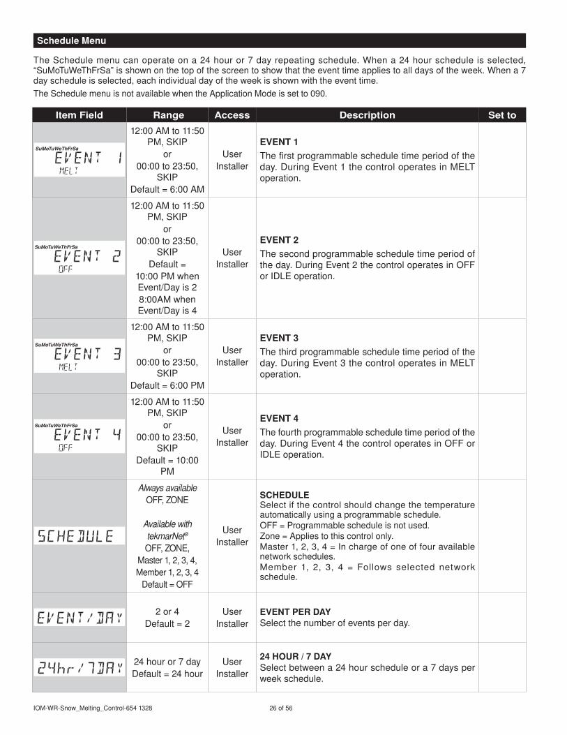
TheSchedulemenucanoperateona24houror7dayrepeatingschedule.Whena24hourscheduleisselected,“SuMoTuWeThFrSa”isshownonthetopofthescreentoshowthattheeventtimeappliestoalldaysoftheweek.Whena7dayscheduleisselected,eachindividualdayoftheweekisshownwiththeeventtime.TheSchedulemenuisnotavailablewhentheApplicationModeissetto090.
Item Field Range Access Description Set to
SuMoTuWeThFrSa
2:00AMto:50PM,SKIP
or00:00to23:50,
SKIPDefault=6:00AM
UserInstaller
EVENT 1Thefirstprogrammablescheduletimeperiodoftheday.DuringEventthecontroloperatesinMELToperation.
SuMoTuWeThFrSa
2:00AMto:50PM,SKIP
or00:00to23:50,
SKIPDefault=
0:00PMwhenEvent/Dayis28:00AMwhenEvent/Dayis4
UserInstaller
EVENT 2Thesecondprogrammablescheduletimeperiodoftheday.DuringEvent2thecontroloperatesinOFForIDLEoperation.
SuMoTuWeThFrSa
2:00AMto:50PM,SKIP
or00:00to23:50,
SKIPDefault=6:00PM
UserInstaller
EVENT 3Thethirdprogrammablescheduletimeperiodoftheday.DuringEvent3thecontroloperatesinMELToperation.
SuMoTuWeThFrSa
2:00AMto:50PM,SKIP
or00:00to23:50,
SKIPDefault=0:00
PM
UserInstaller
EVENT 4Thefourthprogrammablescheduletimeperiodoftheday.DuringEvent4thecontroloperatesinOFForIDLEoperation.
Always availableOFF,ZONE
Available with tekmarNet®
OFF,ZONE,Master,2,3,4,Member,2,3,4
Default=OFF
UserInstaller
SCHEDULESelectifthecontrolshouldchangethetemperatureautomaticallyusingaprogrammableschedule.OFF=Programmablescheduleisnotused.Zone=Appliestothiscontrolonly.Master,2,3,4=Inchargeofoneoffouravailablenetworkschedules.Member , 2, 3, 4 = Follows selected networkschedule.
2or4Default=2
UserInstaller
EVENT PER DAySelectthenumberofeventsperday.
24houror7dayDefault=24hour
UserInstaller
24 HOUR / 7 DAySelectbetweena24hourscheduleora7daysperweekschedule.
Schedule Menu

27of56 ©203WattsRadiant
TheDisplaymenuitemsselectthetemperatureunitsandbacklightoptions.
Item Field Range Access Description Set to
°For°CDefault=°F
UserInstaller
UNITSSelectFahrenheitorCelsiusasthetemperatureunits.
ON,ONMELT,
OFFDefault=ONMELT
UserInstaller
BACkLIGHTSelecthowthedisplaybacklightoperates.ON=Alwayson.ONMELT=Onwhenmelting,offwhennotmelting.Thisprovidesavisualindicatortooccupantsthatthesnowmeltingsystemiscurrentlymelting.OFF=Alwaysoff.
TheScenemenuitemsselectsiftheawaysceneandtheawaykeyareavailable.TheScenesmenuisnotavailablewhentheApplicationModeissetto090.
Item Field Range Access Description Set to
NONEorAWAYDefault=NONE
UserInstaller
SCENESEnableordisabletheuseofscenes(buildingoverrides)onthiscontrol.
OFForONDefault=OFF
UserInstaller
AWAy kEyEnableordisabletheawaytouchkeyonthehomescreen.Condition:ScenesmustbesettoAway.
Display Menu
Scene Menu

IOM-WR-Snow_Melting_Control-654328 28of56
TheMonitormenuitemsprovideinformationaboutthesystem’soperationandperformance.TheMonitormenuisnotavailablewhentheApplicationModeissetto090.
Item Field Range Access Description
0to9999hoursUser
Installer
HEAT HOURSRecordsthenumberofrunninghourssincetheitemwaslastreset.TouchthenumberandthentheENTERkeytoresettozero.
0to9999hours Installer
HEAT CyCLESRecordsthenumberofcyclesoftheheatrelaysincetheitemwaslastreset.TouchthenumberandthentheENTERkeytoresettozero.
0to9999hoursUser
Installer
SySTEM PUMP HOURSRecordsthesystempumprunninghourssincetheitemwaslastreset.TouchthenumberandthentheENTERkeytoresettozero.Conditions:AuxiliaryRelayissettoSYS(systempump).
-58to67°F(-50.0to75.0°C) Installer
SLAB HIGHRecordsthehighestslabtemperaturesincetheitemwaslastreset.TouchthenumberandthentheENTERkeytoreset.Conditions:Snow/IceSensorissetto090orSlabSensorissettoOn.
-58to67°F(-50.0to75.0°C) Installer
SLAB LOWRecordsthelowestslabtemperaturesincetheitemwaslastreset.TouchthenumberandthentheENTERkeytoreset.Conditions:Snow/IceSensorissetto090orSlabSensorissettoOn.
-58to22°F(-50.0to00.0°C) Installer
OUTDOOR HIGHRecordsthehighestoutdoortemperaturesincetheitemwaslastreset.TouchthenumberandthentheENTERkeytoreset.
-58to22°F(-50.0to00.0°C) Installer
OUTDOOR LOWRecordsthelowestoutdoortemperaturesincetheitemwaslastreset.TouchthenumberandthentheENTERkeytoreset.
-58to22°F(-50.0to00.0°C) Installer
SUPPLy HIGHRecordsthehighestsupplytemperaturesincetheitemwaslastreset.TouchthenumberandthentheENTERkeytoreset.Conditions:ApplicationModeissettoPWM,BoilorMix.
-58to22°F(-50.0to00.0°C) Installer
SUPPLy LOWRecordsthelowestsupplytemperaturesincetheitemwaslastreset.TouchthenumberandthentheENTERkeytoreset.Conditions:ApplicationModeissettoPWM,BoilorMix.
-58to22°F(-50.0to00.0°C) Installer
BOILER RETURN HIGHRecordsthehighestboilerreturntemperaturesincetheitemwaslastreset.TouchthenumberandthentheENTERkeytoreset.Conditions:ApplicationModeissettoPWM,BoilorMixandOut/BretSensorissettoRET(return).
-58to22°F(-50.0to00.0°C) Installer
BOILER RETURN LOWRecordsthelowestboilerreturntemperaturesincetheitemwaslastreset.TouchthenumberandthentheENTERkeytoreset.Conditions:ApplicationModeissettoPWM,BoilorMixandOut/BretSensorissettoRET(return).
Monitor Menu

29of56 ©203WattsRadiant
TheToolboxMenuisalocationforsysteminformationandTestfunctions.Ifanyerrorsarepresentonthesystem,theywillbelocatedatthebeginningofthismenu.
Item Field Range Access Description
Installer(INST)User(USER)
Default=INST
UserInstaller
ACCESS LEVELSelecttheaccesslevelofthecontrol,whichdetermineswhichmenusanditemsareavailable.RevertstoUSERaccesslevelafter24hours.Conditions:Toadjust,theswitchsettingonthiscontrolandanyconnectedtekmarNet®systemcontrolmustbesettoUNLOCK.
SoftwareJ226AType654
UserInstaller
SOFTWARE VERSION AND TyPE NUMBERDisplaysthesoftwareversionandtheproducttypenumber.
Notapplicable InstallerFACTORy DEFAULTSLoadsthefactorydefaultsettings.PressENTERtoloaddefaults.
SeeTroubleshootingGuide Installer
HISTORy - 1 THROUGH 5Displaysahistoryofanypasterrorsthathaveoccurredonthesystem.Willclearafter30days,orpresstheCancelkeytomanuallyclear.Thelast5historyitemswilldisplayifpresent.
Toolbox Menu

IOM-WR-Snow_Melting_Control-654328 30of56
TheOverrideMenuallowsanoperatortomanuallytesteachrelayandmanuallystartthesystem.
Item Field Range Access Description
HydronicAUTO,HAND,
MAX,PRGE,OFF
ElectricAUTO,HAND,
TEST,OFF
Default=AUTO
Installer
MANUAL OVERRIDEManuallyoverridethenormalautomaticoperationofthecontroltotesttheequipmentoroperatethesystematthemaximumtemperaturelimits.AUTO=NormaloperationHAND=ManualoverrideofeachrelayoutputMAX=OperatehydronicsystematmaximumheatTEST=Operateelectricsystemfor0minutesPRGE=Hydronicsystempurgeoperatespumpstohelpbleedairfromthesystem
OFForONDefault=OFF
InstallerSySTEM PUMP RELAyManuallyturnonthesystempumpduringtheHANDManualOverride.
OFForONDefault=OFF
InstallerHEAT RELAyManuallyturnontheheatduringtheHANDManualOverride.
0to00%Default=0%
Installer
BOILER PERCENTManuallysetthemodulatingboilerfiringrateduringtheHANDManualOverride.Conditions:ApplicationModeissettoBoil.
0to00%Default=0%
Installer
MIX PERCENTManuallysetthemixingvalveormixinginjectionpumpoutputduringtheHANDManualOverride.Conditions:ApplicationModeissettoMix.
OFForONDefault=OFF
Installer
ALERT RELAyManually turnonthealert relayduringtheHANDManualOverride.Conditions:ApplicationModeissettoPWM,BoilorMixandAlertRelayissettoALRT(alert)ortheApplicationModeissettoElec.
0:0to72:00hours
Default=0:0hours
InstallerOVERRIDE TIMESelecttheamountoftimethattheHANDManualOverrideisineffectbeforereturningtoAutomaticoperation.
0:0to72:00hours
Default=24:00hours
Installer
MAXIMUM PURGE TIMESelecttheamountoftimethatthePURGEManualOverrideisineffectbeforereturningtoAutomaticoperation.Conditions:ApplicationModeissettoPWM,BoilorMix.
0:0to72:00hours
Default=24:00hours
Installer
MAXIMUM HEAT TIMESelecttheamountoftimethattheMAXHEATManualOverrideisineffectbeforereturningtoAutomaticoperation.Conditions:ApplicationModeissettoPWM,BoilorMix.
Override Menu

3of56 ©203WattsRadiant
TheSystemMenuprovidessettingsonhowtoconfigureandoperatethemechanicalequipment.
Item Field Range Access Description Set to
PWM,BOIL,MIX,ELEC,090
Default=PWMInstaller
APPLICATION MODESelectthecontrolapplicationmode.PWM=HydronicPulseWidthModulation.BOIL=Hydronicboilerheatssnowmeltingsystem.MIX=Hydronicmixingvalveorinjectionpumpheatssnowmeltingsystem.ELEC=Electricsnowmelt.090=TandemSnow/IceDetectionusing090
NONE,090,095
Default=090
InstallerSNOW / ICE SENSORSelectifaSnow/IceSensor090orSnowSensor095isinstalled.
OFForONDefault=ON
Installer
SLAB SENSORSelectifaSlabSensor072isinstalledtomeasuretheslabtemperature.Conditions:ApplicationModeissettoPWM,BoilorMixandSnow/IceSensorissettoNoneor095.
OFForONDefault=ON
Installer
SLAB PROTECTIONSelect if theslabshouldbeprotectedfromlargetemperaturedifferentialstoavoidcrackingtheconcreteduetohightensilestress.Conditions:ApplicationModeissettoBoilorMixandSnow/IceSensorissetto090orSlabSensorissettoOn.
OFF,OUT(Outdoor)or
BRET(BoilerReturn)Default=OUT
Installer
OUTDOOR OR BOILER RETURN SENSORSelectiftheOut/Bretwiringterminalisconnectedtoanoutdoorsensororaboilerreturnsensor.Conditions:ApplicationModeissettoPWM,BoilorMixorElec.
OFForONDefault=OFF
Installer
ECONOMELTEconoMeltallowstheusertomechanicallyremovesnowthenmanuallystartthesystemtomeltthethinsnowlayerorice.Conditions:ApplicationModeissettoPWM,BoilorMixorElec.
OFForONDefault=ON
Installer
tekmarNet® SySTEM PUMPSelectifthesystempumplocatedonthetekmarNet®SystemControlshouldoperatewhenthesnowmeltzoneisheating.Conditions:ApplicationModeissettoPWM,BoilorMixandBoilerTypeissettoCTRL(tN4control).
SYS(SystemPump)or
ALRT(Alert)Default=SYS
Installer
AUXILIARy RELAySelectiftheauxiliaryrelayshouldfunctionassystempumporasanalert.Conditions:ApplicationModeissettoPWM,BoilorMix.
0.5to7.0days,OFFDefault=3.0days
Installer
MAXIMUM MELT TIMESelecttolimittheamountofmeltingruntimeaftersnowisautomaticallydetectedbyaSnow/IceSensor090oraSnowSensor095.Conditions:ApplicationModeissettoPWM,BoilorMixorElec.
System Menu
IOM-WR-Snow_Melting_Control-654328 32of56
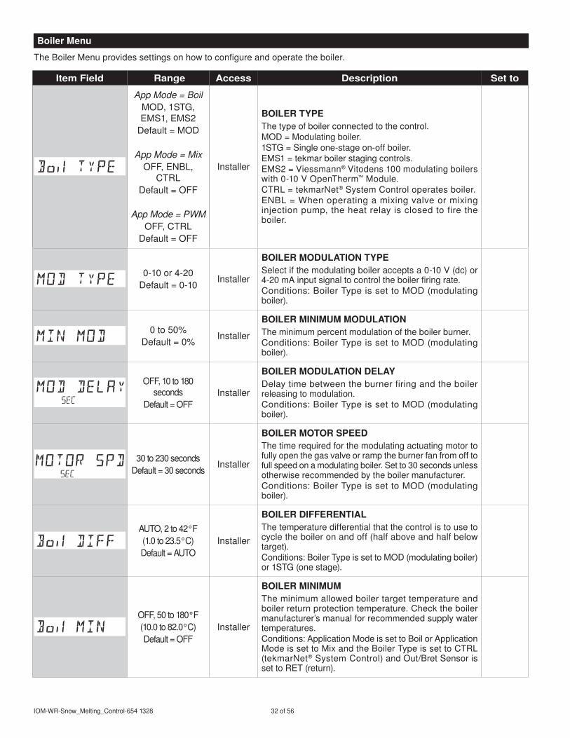
TheBoilerMenuprovidessettingsonhowtoconfigureandoperatetheboiler.
Item Field Range Access Description Set to
App Mode = BoilMOD,STG,EMS,EMS2
Default=MOD
App Mode = MixOFF,ENBL,
CTRLDefault=OFF
App Mode = PWMOFF,CTRL
Default=OFF
Installer
BOILER TyPEThetypeofboilerconnectedtothecontrol.MOD=Modulatingboiler.STG=Singleone-stageon-offboiler.EMS=tekmarboilerstagingcontrols.EMS2=Viessmann®Vitodens00modulatingboilerswith0-0VOpenTherm™Module.CTRL=tekmarNet®SystemControloperatesboiler.ENBL=Whenoperatingamixingvalveormixinginjectionpump,theheatrelayisclosedtofiretheboiler.
0-0or4-20Default=0-0
Installer
BOILER MODULATION TyPESelectifthemodulatingboileracceptsa0-0V(dc)or4-20mAinputsignaltocontroltheboilerfiringrate.Conditions:BoilerTypeissettoMOD(modulatingboiler).
0to50%Default=0%
Installer
BOILER MINIMUM MODULATIONTheminimumpercentmodulationoftheboilerburner.Conditions:BoilerTypeissettoMOD(modulatingboiler).
OFF,0to80seconds
Default=OFFInstaller
BOILER MODULATION DELAyDelaytimebetweentheburnerfiringandtheboilerreleasingtomodulation.Conditions:BoilerTypeissettoMOD(modulatingboiler).
30to230secondsDefault=30seconds
Installer
BOILER MOTOR SPEEDThetimerequiredforthemodulatingactuatingmotortofullyopenthegasvalveorramptheburnerfanfromofftofullspeedonamodulatingboiler.Setto30secondsunlessotherwiserecommendedbytheboilermanufacturer.Conditions:BoilerTypeissettoMOD(modulatingboiler).
AUTO,2to42°F(.0to23.5°C)Default=AUTO
Installer
BOILER DIFFERENTIALThetemperaturedifferentialthatthecontrolistousetocycletheboileronandoff(halfaboveandhalfbelowtarget).Conditions:BoilerTypeissettoMOD(modulatingboiler)orSTG(onestage).
OFF,50to80°F(0.0to82.0°C)Default=OFF
Installer
BOILER MINIMUMTheminimumallowedboilertargettemperatureandboilerreturnprotectiontemperature.Checktheboilermanufacturer’smanualforrecommendedsupplywatertemperatures.Conditions:ApplicationModeissettoBoilorApplicationModeissettoMixandtheBoilerTypeissettoCTRL(tekmarNet®SystemControl)andOut/BretSensorissettoRET(return).
Boiler Menu

33of56 ©203WattsRadiant
TheMixMenuprovidessettingsonhowtoconfigureandoperatethemixingvalveormixinginjectionpump.TheMixmenuisonlyavailablewhentheApplicationModeissettoMix.
Item Field Range Access Description Set to
0-0or4-20Default=0-0
Installer
MIX TyPESelectthetypeofmixinganalogsignal.0-0=0to0V(dc)4-20=4to20mA
30to230seconds
Default=05seconds
Installer
MIX MOTOR SPEEDThetimethatthemixactuatingmotorrequirestooperatefromfullyclosedtofullyopen.MixingInjectionPump=30secondsRefertoactuatingmotorforcorrectsetting.
80to80°F(26.5°Cto82.0°C),
OFFDefault=40°F
(60°C)
InstallerMIX MAXIMUMSelectthemaximumoperatingtemperatureofthesystemsupplywater.
Mix Menu

IOM-WR-Snow_Melting_Control-654328 34of56
Item Field Range Access Description Set to
Range:AUTO,0to24,
b:0tob:24,:0to:24,2:0to2:24,3:0to3:24
InstallerADDRESSThetekmarNet®addressofthiscontrol.Tomanuallysettheaddress,usetheupordownarrowbuttons.
to24 InstallerDEVICE COUNTProvidesacountofallthetekmarNet®thermostats,setpointcontrolsandsnowmeltingcontrolsonthetekmarNet®system.
to2Default=
InstallerSNOW ZONESelecttheSnowZonethatthiscontroloperates.SnowZonehasthehighestprioritywhileSnowZone2hasthelowestpriority.
OFForONDefault=OFF
Installer
TRACk ZONESelecttotrackandrecordthemeltruntimeofSnowZoneandrepeatsthisruntimeonthiscontrol.Thisallowssnowzoneswithoutasnow/icesensortoautomaticallystart.Conditions:SnowZonemustbeset2through2(cannotbeSnowZone)andApplicationModeissettoPWM,Boil,MixorElec.
to2Default=
Installer
MELT GROUPAUserSwitchmaybeusedtomanuallystartmeltingthesnowzone.SettheMeltGroupnumbertothecorrespondingSetpointEnablenumberontheUserSwitch.Conditions:ApplicationModeissettoPWM,Boil,MixorElec.
to2Default=2
Installer
STORM GROUPAUserSwitchmaybeusedtomanuallystartstormoperationofthesnowzone.SettheStormGroupnumbertothecorrespondingSetpointEnablenumberontheUserSwitch.Conditions:ApplicationModeissettoPWM,Boil,MixorElec.
OFF,COND,FULL
Default=OFFInstaller
PRIORITySelectthepriorityoperationofthesnowmeltingsystem.Conditions:ApplicationModeisPWM,MixorElec.
OFForONDefault=OFF
Installer
LOCAL NETWORk GROUPSelectifscenesandtimeclockaresharedwhenconnectedtoatekmarNet®system.OFF=Sendandreceivemessages.ON=Receivemessagesonly.Conditions:ApplicationModeissettoPWM,Boil,MixorElec.
ThetekmarNet®menuincludessettingsofhowthesnowmeltingcontrolcommunicatesandoperatestogetherwithothercontrols.ThetekmarNet®menuisonlyavailablewhencommunicationisdetected.
tekmarNet® Menu

35of56 ©203WattsRadiant
Sequence of Operation
Asnowmeltingsystemcanofferasafe,convenient,andcosteffectivewayofremovingsnowandicefromthesnowmeltingslabandsimilarsurfaces.Safetyisincreasedbyactivatingthesnowmeltingsystemassoonasthesnowfallsratherthanwaitingformechanicalsnowremovalaftersnowhasaccumulated.Thiseliminatessliphazardsandreducestheriskofinjurybymechanizedsnowmeltingequipment,therebyreducingpotentialliabilitycosts.Theeliminationofsnowplowequipmentandcorrosivesaltsalsoreducesdamagetotheslabsurfaceandtotheenvironment.Snowmeltingsystemswhencontrolledcorrectlycanbecostcompetitivecomparedtomechanicalsnowremoval.
Thesnowmeltingcontrolcanoperateinoneoffourdifferentways:
Melt HeatstheslabtomeltsnoworiceIdle Pre-heatstheslabjustbelowfreezingtoshortenthe
timerequiredtomeltsnowStorm Temporarilypre-heatstheslabjustbelowfreezingto
shortenthetimerequiredtomeltsnowOff SnowmeltingsystemisoffThecontroldisplayshowsthecontroloperationinthehomescreen.
Thesnowmeltingsystemoperatestheheatingequipmenttoheattheslabfromacoldstartorfromtheidleorstormtemperaturetoreachthemelttemperaturesettingtomeltsnoworice.Meltoperationcanbetriggeredautomaticallyusingasnow/icesensor,bytrackingtheruntimeofanother
zone,manuallybypressingabutton,orbyaprogrammableschedule.Themelttemperaturesettingaffectscalculatedtargetssuchastheslabtarget,boilertargetandmixtarget.
Controllingtheslabtemperatureiscriticaltominimizingthecostofsnowmelting.ThisrequiresthateitheraSnow/IceSensor090oraSlabSensor072isinstalled.TheSnow/IceSensorcontainsabuilt-inslabtemperaturesensor.Whilethecontrolwillcontinuetooperatewithoutaslabsensorinstalled,operatingcostswillbemuchhigher.Theslabisoperatedusingslaboutdoorreset.Astheoutdoortemperaturegetscolder,theheatlossoftheslabincreases.Inordertokeeptheslabsurfaceataconstanttemperaturewhileoperating,theinnercoreoftheslabmustbeheatedabovethemelt,idleorstormtemperaturesetting.Theamountthattheslabinnercoretemperatureisabovethemelt,idleorstormsettingisproportionaltotheoutdoortemperature.Sincetheslabsensorisinstalledbelowthesurfaceoftheslab,itisnotmeasuringthetrueslabsurfacetemperaturebutrathertheinnercoretemperature.Thecontrolautomaticallycompensatesforthistemperaturedifference.However,theSlabitemintheViewmenudisplaystheactualmeasured
temperature,soitisnormaltoviewslabtemperaturesthatexceedthemelt,idle,orstormtemperaturesettings.
Surface temperature = 35°F
Decreasing Air Temperature
Incr
easi
ng S
lab
Cor
e Te
mpe
ratu
re
SlabSurfaceTemperatureisConstant
SlabOutdoorResetSlabOutdoorReset
Core(sensor)iswarmer
Snow Melting Overview
Slab Temperature Control
Melt Operation

IOM-WR-Snow_Melting_Control-654328 36of56
ThesnowmeltingsystemcanbestartedmanuallybytouchingtheMeltkeyonthecontroldisplay.Oncemanuallystarted,thesnowmeltingsystemcontinuestooperateuntilthetimesetbytheManualMeltRunTimesettingintheSetTempmenuelapses.
TouchMELTkey
095detectswater
Trackedzonemelt
UserSwitch/GatewayEnable
MANUALMELTRUNTIMEelapses
AWAYscene
Trackedzonetimeelapses
TouchSTOPkey
WWSD
UserSwitch/GatewayDisable
CWCO
TimedMeltor
Idle
Off
095detectswater
PressMelt
IfamanualstarthasbeenprovidedandaSnow/IceSensordetectswater,thecontrolchangesfrommanualmelttoautomaticoperation.ThesnowmeltingsystemwillcontinuetooperateuntilthesensorisdryandtheAdditionalMeltTimeelapses.
AutomaticstartandstopoperationrequirestheinstallationofaSnow/IceSensor090.Thecontrolcontinuallymonitorsthesensorforthepresenceofmoistureandslabtemperatureconditionsinwhichsnoworicemaybepresent.Whenmoistureisdetected,thecontrolwillshow“SensorWaterWet”intheViewmenu.Whenthesensorisdrythecontrolwillshow“SensorWaterDry”.ThecontrolincludesaSensitivitysettingintheSetTempmenuthatallowstheinstallertoadjusttheamountofmoisturerequiredtostartandstopthemeltingoperation.Inareaswithlowamountsofdustand/orairpollution,thesensitivitymayneedtobeincreased.TheSensitivitysettingdefaultisAuto,andthecontrolwillautomaticallydeterminethebestsuitablesensitivitysettingfortheinstallation.
TouchSTOPkey
090andslabdryandADDMELTtimeelapses
or
Idle
OffAWAYscene
WWSD
090detectswater
ExitsCWCOMelt
Suspended
EntersCWCO
AutoMelt
UserSwitch/GatewayDisable
Whenmoistureisdetectedandtheslabandoutdoortemperaturesareatorbelowmeltingsetting,thecontrolwillautomaticallystartthesnowmeltingsystem.Asthesnoworicemeltsandtheslabdriesoff,thesensoralsodriesoffatthesametime.Whenthesensorisdry,thesnowmeltsystemautomaticallyshutsoff.Iftherearelowspotsontheslabsurfacethatdryoffslowerthanthesensor,additionalmeltingruntimecanbeincludedbyadjustingtheAdditionalMeltTimesettingintheSetTempmenu.Ifthesnowmeltingsystemismanuallystopped,theSnow/IceSensormustfullydrybeforeitisabletodetectanewsnowfallandautomaticallystartthesnowmeltingsystem.
Snow / Ice Sensor 090
Melt - Manual Start and Timed Stop
Melt - Automatic Start and Stop
RemoteaccesstostartthesystemcanoptionallybeprovidedwithatekmarNet®UserSwitchorGatewayfromtekmarControlSystems.

37of56 ©203WattsRadiant
AutomaticstartwithatimedstopoperationrequirestheinstallationofaSnowSensor095.ItisalsohighlyrecommendedtoinstallaSlabSensor072inordertoregulatetheslabtemperatureandoperatethesnowmeltingsystematthehighestpossibleefficiency.Thecontrolcontinuallymonitorsthesensorforthepresenceofmoistureandslabtemperatureconditionsinwhichsnoworicemaybepresent.Whenmoistureisdetected,thecontrolwillshow“SensorWaterWet”intheViewmenu.Whenthesensorisdrythecontrolwillshow“SensorWaterDry”.ThecontrolincludesaSensitivitysettingintheSetTempmenuthatallowstheinstallertoadjusttheamountofmoisturerequiredtostartandstopthemeltingoperation.Inareaswithlowamountsofdustand/orairpollution,thesensitivitymay
needtobeincreased.ThefactorydefaultisfortheSensitivitysettingisAuto.Thecontrolautomaticallydeterminesthebestsuitablesensitivitysettingfortheinstallation.WhenmoistureisdetectedandboththeslabandoutdoortemperaturesarebelowtheMeltingsetting,thecontrolautomaticallystartsthesnowmeltingsystem.ThesnowmeltingsystemoperatestoheattheslabtotheslabtargettemperatureandcontinuestooperateuntilthetimesetbytheManualMeltRunTimeintheSetTempmenuelapses.
WhenaSnow/IceSensor090isinstalled,theinstallercanchoosetoselecttoeitherautomaticallyormanuallystartthesnowmeltingsystem.SelectingEconoMelttoOnprovidestheoptiontoremovethesnowusingasnowploworshovelandthenusethesnowmeltingsystemtomelttheremainingthinlayerofsnoworicethatmechanicalsnowremovalmethodsareunabletoremove.Thesnowmeltingsystemstopswhenthesensorisdry.ThefactorydefaultforEconoMeltisOff.
TouchMELTkey
095detectswater
Trackedzonemelt
UserSwitch/GatewayEnable
MANUALMELTRUNTIMEelapses
AWAYscene
Trackedzonetimeelapses
TouchSTOPkey
WWSD
UserSwitch/GatewayDisable
CWCO
TimedMeltor
Idle
Off
095detectswater
TouchSTARTkey
090andslabdryandADDMELTtimeelapses
AWAYscene
TouchSTOPkey
WWSD
UserSwitch/GatewayDisable
MeltOff
ExitsCWCOMelt
Suspended
EntersCWCO
Snow Sensor 095
Melt - EconoMelt
Melt - Automatic Start and Timed Stop

IOM-WR-Snow_Melting_Control-654328 38of56
Thesnowmeltingsystemcanhavemultiplezones.Zoneshavetheoptiontotrackthemeltingruntimeofzone.ThisisusefulincaseswherezonehasanautomaticSnow/IceSensorinstalledandtheremainingzonesdonot.Thisallowszones2to2togainthefunctionalityofautomaticstartingandstoppingwithonlyoneSnow/Icesensorinstalledinthesystem.Whenzonedetectssnoworice,itstartsmelting.Zoneswithtrackingenabledcanalsostartmeltingunlesspriorityisselected.WhenthesensorinzoneisdryortheManualMeltRunTimehasfullyelapsed,itsendsasignaltothetrackedzonesthatzonehasstopped.EachzonecancontinuetooperatetocompletetheirownAdditionalMeltTimeafterwhichthezonestopsheatingandreturnstotheOfforIdleoperation.Zoneswithpriorityselectedstartafterzonehasfinishedmeltingandrepeatthesameruntimeaszone.
Thesnowmeltingsystemcanbestartedbaseduponaprogrammableschedule.Thetimeclockmustcrosspastthescheduledeventtimeinordertostartorstop.Inaddition,operationisdependentonwhetherornotaslabsensor,snow/ice,snowsensorornoslabsensorisinstalled.Theuseofaprogrammablescheduleiswellsuitedforcommercialinstallationswhereoperationisnotrequired24hoursaday.
Systems With Automatic Detection------------------ThisapplieswhenaSnow/IceSensor090orSnowSensor095isinstalled.WhenthetimeclockreachesthescheduleEvent(wake)time,thesystemisallowedtomeltifthesensordetectssnoworice.WhenthetimeclockreachesthescheduleEvent2(unoccupied)time,thesystemisofforinidleoperation.WhenthetimeclockreachesthescheduleEvent3(occupied)time,thesystemisallowedtomeltifthesensordetectssnoworice.WhenthetimeclockreachesthescheduleEvent4(sleep)time,thesystemisofforinidleoperation.
Systems Without Automatic Detection--------------ThisapplieswhenaSlabSensor072ornoslabsensorisinstalledandthereisnoautomaticdetection.WhenthetimeclockreachesthescheduleEvent(wake)time,thesystemisinmeltoperation.WhenthetimeclockreachesthescheduleEvent2(unoccupied)time,thesystemisofforinidleoperation.WhenthetimeclockreachesthescheduleEvent3(occupied)time,thesystemisinmeltoperation.WhenthetimeclockreachesthescheduleEvent4(sleep)time,thesystemisofforinidleoperation.
Scheduleevent2
Scheduleevent4
TouchSTOPkey
AWAYscene
WWSD
UserSwitch/GatewayDisable
CWCO
Scheduleevent
Scheduleevent3
or
Idle
Off
ScheduledMelt
Zone
TrackMeltStartandStop
RecordsRun Time
Snow / IceSensor
SlabSensor
SlabSensor
Zone2 Zone3
RepeatsZone 1 RunTime + AddMelt Time
RepeatsZone 1 RunTime + AddMelt Time
Melt - Tracked Start and Stop
Melt - Scheduled Start and Stop

39of56 ©203WattsRadiant
Whenthesnowmeltingsystemstartsfromacoldtemperature,theremaybealongtimedelaybeforetheslabiswarmenoughtomeltsnow.Thistimedelayallowssnowtoaccumulateontheslabwhichisnotacceptableinsomecommercialandinstitutionalapplications.Todecreasethestartuptime,theslabcanbepre-heatedtomaintainaminimumtemperature.ThisisknownastheIdletemperature.Idlingrequireslargeenergyconsumptionandisgenerallyrecommendedforinstitutionaland/orcommercialinstallationswheresafetyconcernsareparamount.Idleisshownonthedisplaywhenthecontrolisinidleoperation.Whendesigningasnowmeltingsystem,anengineermayspecifytheamountofallowedsnowaccumulationastheSnow-FreeAreaRatio.Therearethreedifferentlevels.ASnow-FreeAreaRatioofisdefinedasasystemthatmeltsallsnowasitfallswithnoallowedaccumulation.ThisrequiresthattheIdletemperaturebesetjustbelowfreezing.Examplesofthesetypesofapplicationsinclude:
HospitalemergencyareasHelicopterlandingpadsParkinggarageramps
ASnow-FreeAreaRatioof0.5isdefinedasasystemwithpartialsnowaccumulationontheslabbutnotinallareas.ThesetypesofsystemsmayalsouseIdlingbutusuallysetatatemperatureseveraldegreesbelowfreezingtoreduce
•••
energyconsumption.Applicationsmayinclude:SteepresidentialdrivewaysCommercialsidewalksLoadingdocks
ASnow-FreeAreaRatioof0isdefinedasasystemthatallowssnowaccumulation.Thesesystemsoperatethesnowmeltingsystemfromacoldstartresultinginthelowestenergyconsumptioncostsandthelongesttimestostartmeltingsnow.InthiscasesettheIdletooff.Thisisrecommendedformostresidentialapplications:
FlatresidentialdrivewaysPatiosResidentialsidewalks
Somesystemsaredesignedforkeepingaslabsurfacefreeoficeratherthanfreeofsnow.Themostcommonapplicationsinclude:
CarwashbaysandapronsAircrafthangerapronsTurfconditioningongolfcoursegreens
ThesesystemsrequiretheuseofIdlingatornearfreezingthroughout thewinterandmayresult inhighenergyconsumption.
•••
•••
•••
DrySnow Ice Sensor
ASnow/IceSensor090automaticallyshutsoffthesnowmeltingsystemwhenthewatersensorisdry.Duetotheconstructionoftheslabandthelayoutoftheheatingpipeorelectricalcable,theremaybeareasthatdonotmeltcompletely.TheAdditionalMeltTimesettingintheSetTempmenuallowstheinstallertosetadditionmeltingtimeafterthesensorisdry.
FormanyresidentialapplicationsitistoocostlytoIdlethesnowmeltsystemallwinter.TheStormfeatureprovidesatemporarypre-heatinsystemswhereatekmarNet®UserSwitchorGatewayisinstalled.Stormcombinesthebenefitsofafastresponsetimetogetherwithloweroperatingcosts.Stormoperationdoesthisbyallowingtheusertoactivateatemporarypre-heatoftheslabintheeventofasnowfallwarning.Ifsnowisdetectedorthesystemismanuallystarted,thesnowmeltsystemheatstheslabuptothemeltingtemperatureandcompletesameltingcycle.Shouldnosnowfallduringthestormtimeperiod,thecontrolexitsStormoperationandreturnstoOff.TheStormoperationissetupbysettingtheStormtemperatureandtheStormRunTimeintheSetTempmenu.TheStormoperationcanonlybeactivatedbyatekmarNet®UserSwitchorGateway.TorespondtoaUserSwitchorGateway,selectaStormGroupnumberfromto2.ThenprogramtheUserSwitchorGatewaysetpointenabletobethesameastheStormGroupnumber.PressingtheprogrammedUserSwitchbuttonwillnowactivatetheStormoperationonthesnowmeltingcontrol.OntheGateway483,activatingthestormgroupon
Melt
Away
StormPressStorm
theScenespageinturnenablestheStormoperation.TheGateway482includesasetpointenablecommandthatallowsahomeautomationsystemtoenabletheStormoperation.Checkwiththehomeautomationcompanytodetermineifthisfeatureissupported.
Additional Melting Time
Idle Operation
Storm Operation
FormoreinformationabouttekmarNet®UserSwitchesandGateways,visittekmarControls.com.

IOM-WR-Snow_Melting_Control-654328 40of56
Duringwarmweather,theslabiswarmenoughtonaturallymeltsnoworice.ThecontrolhasaWarmWeatherShutDown(WWSD)settingintheSetTempmenuthatpreventsthecontrolfromenteringMelt,IdleorStormoperationinordertoconserveenergy.ThecontrolshowsWWSDonthedisplaywhenWWSDisineffect.
Automatic (Auto)ThecontrolentersWWSDwhenboththeslabtemperatureofazoneandtheoutdoortemperatureexceedtheMelttemperaturesettingbymorethan2°F(°C).
Manual WWSDThecontrolentersWWSDwhentheoutdoorairtemperatureexceedstheWWSDsettingby°F(0.5°C)andwhentheslabtemperatureexceeds34°F(°C).ThecontrolexitsWWSDwhentheoutdoorairtemperaturefalls°F(0.5°C)belowtheWWSDsettingoriftheslabtemperaturefallsbelow34°F(°C).ThisallowstheMelttemperaturesettingtobesethigherthantheWWSD.Thisisusefulwhenhighslabtemperaturesarerequiredtomeltthesnoworice.Anexampleofthisareinstallationsusingpavingbricksontopofsandandconcretelayers.
Maintainingthemeltingoridlingtemperatureduringextremelycoldtemperaturesisnotonlyexpensivebutmaybeimpossibleiftheheatlossoftheslabexceedstheinputcapacityoftheheatingplantorelectriccable.ThecontrolturnsthesnowmeltingsystemoffwhentheoutdoorairtemperaturedropsbelowtheColdWeatherCutOut(CWCO)temperatureandtheslabisbelowfreezingasanenergysavingmeasure.ThecontrolshowsCWCOonthedisplaywhenCWCOisin
effect.WhenthetemperaturereachestheCWCOsettinginanactivelymeltingsystemwithan090,meltingissuspendeduntiltheoutdoortemperaturerisesabovetheCWCOsetting.Ifan090isnotinstalled,meltingispermanentlystoppedwhenCWCOisineffect.MeltingdoesnotresumewhenthetemperaturerisesabovetheCWCOsetting.
Scenesprovideaneasywaytosaveenergywhileawayonvacation,oroverrideaprogrammableschedulewhenplanschange.
Away key-------------------------------------------ThiscontrolincludesanAwayKeytoquicklydisablethesnowmeltingsystem,andwhenconnectedtoatekmarNet®system,canalsoturndowntheheatingtemperatureonallthermostatsandsuspendheatingthedomestichotwatertanktomaximizeenergysavings.ToturnontheAwayKey,gototheScenemenu.ToactivatetheAwayscene,touch“GoingAway”onthescreen.
Storm
Melt
AwayPressAway
SelectPERM(permanent)oranumberofdaysusingtheor arrow.Rangeisto80days.
Pressthehomebuttontoacceptthesettingorleavethescreenuntouchedforseveralseconds.“SceneAway”isdisplayedonthehomescreenuntilthenumberofdaysexpires.Touch“CancelAway”tocancelatanytime.
User Switch--------------------------------------AtekmarNet®UserSwitchavailablefromtekmarControlSystemsmaybeusedtoactivatetheAwayscene.
•
•
•
•
Additional Scenes--------------------------------Thesnowmeltingcontrolsupportsscenes(normal)2(away)and3(unoccupied).Scene3disablesthesnowmeltingsystem.WhenthetekmarNet®systemissettoscene4through8,thesnowmeltingcontrolremainsinscene.
Warm Weather Shut Down
Cold Weather Cut Out
Away Scene

4of56 ©203WattsRadiant
Toprovidegreaterenergysavings,thecontrolcanoperateonaprogrammableschedule.Thescheduleisstoredinmemoryandisnotaffectedbylossofpowertothecontrol.IftekmarNet®communicationisdetectedthecontrolcanbecomeeitheraschedulememberorschedulemaster.
Zone Schedule--------------------------------------Thescheduleonlyappliestothecontrol.ThecontrolfollowsitsownscheduleandtheeventsarenotcommunicatedtothetekmarNet®system.
Master Schedule------------------------------------IfthecontrolisconnectedtoothertekmarNet®devices,thenthecontrolcanoperateonamasterschedule.AmaximumoffourmasterschedulesareavailableonthetekmarNet®
system.Usingmasterschedulessimplifyinstallationsinceonemasterschedulemaybeusedbymultipledevices.
To create a master schedule:AssignthecontroltobeaschedulemasterbysettingScheduleintheSchedulemenutoMaster(MST)to4.
•
To follow a master schedule:AssignthecontroltofollowamasterschedulebysettingScheduleintheSchedulemenutoMember(MBR)to4.
Schedule Types-------------------------------------Thescheduletypedetermineswhentheschedulerepeatsitself.Thiscontrolincludestwodifferentscheduletypes:•24Hour:Repeatsevery24hours.
•7Day:Repeatsonaweeklybasisandallowsforseparateeventtimesforeachday.
Events / DayTheevents/daycanbeeither4or2.Aneventisatimeatwhichthecontrolchangesthetargettemperature.Theeventtimecanbesettothenearest0minutes.Tohavethecontrolskiptheevent,enter“SKIP“asthetime.SKIPisfoundbetween:50PMand2:00AMor23:50and00:00hours.
•
Thecontrolhasabuilt-intimeclocktoallowthecontroltooperateonaschedule.Abattery-lessbackupallowsthecontroltokeeptimeforupto4hourswithoutpower.Thetime
clocksupportsautomaticadjustmentforDaylightSavingTime(DST)oncetheday,monthandyearareentered.UsetheTimemenutosetthecorrecttime,day,monthandyear.
Dividingasystemintoanumberofsnowmeltingzonesandprioritizingthezoneoperationreducesthesizerequirementsofthehydronicheatingplantortheamperageoftheelectricalservicepanel.Thisresultsinlowerinitialcapitalcostofthesnowmeltingsystem.Thetradeoffisthatsomesnowmeltzonesmaynotbeabletomeltassoonasthesnowfallbeginsandtheusermusttoleratesnowaccumulationontheslab.Thesnowmeltsystemmayhaveupto2snowmeltzones.Zonehasthehighestpriorityandzone2hasthelowest.TheprioritysettinginthetekmarNet®menuallowstheinstallertoselectthelevelofzonepriorityfortheentiresnowmeltsystem.Changingtheprioritysettingononecontrolwillupdateonallothersnowmeltcontrolsatthesametime.Thezonepriorityhas3settinglevels.Thereissomeriskthat
lowerpriorityzonesmayiceupwhentheyareshutoffbythehigherpriorityzone.Forexample,ifahighpriorityzoneshouldfinishmeltingandallowalowerpriorityzonetostartmelting,andthenanewsnowfalloccurs,thehighpriorityzonewillshutoffthelowerpriorityzones.Thismaypotentiallyallowthelowerpriorityzonestoiceover.Thelimitationsofzoningandusingprioritymustbecarefullyconsideredanddiscussedwiththebuildingownersandoccupantswhendesigningthesnowmeltingsystem.PrioritydoesnotapplywhentheapplicationmodeissettoBoiler.Inthismode,theboilerisdedicatedtoasinglesnowmeltingzonesopriorityisnolongerapplicable.
Programmable Schedules
Time Clock
Snow Melt Zones and Priority

IOM-WR-Snow_Melting_Control-654328 42of56
Priority = NoneAllzoneshavethesamepriorityandcanoperateatthesametime.Thissettingisrecommendedwhentheboilerplantcapacityissizedlargerthantheheatlossofallzonesatdesignconditions.
Priority = ConditionalThezonewiththelowerprioritystartsmeltingwhenthezonewithhigherpriorityiswarmenoughtomeltsnoworice.Thissettingisrecommendedwhentheboilerplantcapacityissizedtobelargerthantheheatlossofeachzonewithsomeextracapacity.
Priority = FullThezonewiththelowerprioritystartsmeltingoncethezonewithhigherpriorityhasfinishedmeltingallsnoworicefromtheslab.Thissettingisrecommendedwhentheboilerplantcapacityissizedtobethesameastheheatlossofeachzoneatdesignconditions.
Hydronic Priority Levels--------------------------------------------------------------------------------
Electric Priority Levels---------------------------------------------------------------------------------Electricsnowmeltingoffersthreelevelsofpriority:None,ConditionalandFull.TheNoneandFullpriorityoptionsfunctionthesameaswiththehydronicoperation.TheConditionalpriorityisuniquetoelectricaloperation.Thehighestpriorityzoneoperatesfirst.Wheneverthehighestpriorityzoneshuts
offitsrelay,thelowerpriorityzoneisallowedtostartmeltingandcloseitsrelay.Onlyoneelectricalrelayisallowedtobeonatanytime.Thiseliminateslargeinstantaneousdemandsandavoidssurchargesfromtheelectricalutility.
Zone 1
MELT
OFF
Zone 2
MELT
OFF
Zone 1
MELT
OFF
Zone 2
MELT
OFF
Zone 1
MELT
OFF
Zone 2
MELT
OFF
Zone 1
MELT
OFF
Zone 2
MELT
OFF
Zone 1 Relay
ON
OFF
Zone 2 Relay
ON
OFF

43of56 ©203WattsRadiant
Inahydronicsnowmeltingsystem,theboilerorheatingplantcapacitymaybemuchlargerthantheloadofthesnowmeltingzones.Thiscanresultinlargetemperaturedifferentialsbetweenthesupplywatertemperatureandtheslabcreatinglargetensilestressesontheslab.Concreteisweaktotensileforcesandwhenrepeatedlyexposedtotensileloadstheconcretemaycrack.ThismaybepreventedbyselectingtheProtectSlabsettingintheSystemmenutoOn.Thecontrolmeasuresandlimitsthetemperaturedifferentialbetweenthesupplywaterandtheslab.
tensile stresses
Thesnowmeltingcontrolcanoperateeitheranelectricorahydronicsnowmeltingsystem.Ahydronicsystemcanbefurthercategorizedaseitherboiler,mixingorpulsewidthmodulationzoneoperation,aswellas,whethertheboilerplantisdedicatedornon-dedicatedforthesnowmeltingsystem.Adedicatedboileronlyprovidesheatforthesnowmeltingsystem.Anon-dedicatedboilerprovidesheatforthesnowmeltingsysteminadditiontothespaceheatingand/ordomestichotwatersystem.Thecontrolrequires
thatoneofthefollowingApplicationModesisselectedintheSystemmenu:
PWM PulseWidthModulationBOIL BoilerOperationMIX MixingOperationELEC ElectricalOperation090 TandemSnow/IceDetectionusingan090
•••••
Thecontroloperatestheheatrelayona20minutepulsewidthmodulationcycle.Theheatrelayinturnactivatesalinevoltageelectricalcontactortoenergizetheelectricalcableheaterinstalledintheslab.Theheatrelayontimeisdeterminedbythecalculatedslabtargetandbythemeasuredslabtemperaturereading.Astheslabtemperaturereachestheslabtarget,theontimepercycleoftheheatrelayis
reducedtopreventtheslabtemperaturefromovershooting.Ifnoslabsensorisinstalledtheheatrelayremainson00%ofthetimeuntiltheMeltoperationhascompleted.IdleandStormoperationarenotavailablewhenaslabsensorisnotinstalled.Theelectricoperationrequirestheinstallationofanoutdoorsensor.Aslabsensorishighlyrecommendedinordertoreduceoperatingcosts.
TheApplicationModeshouldbesettoPulseWidthModulation(PWM)whentheboilerorheatsourceisnon-dedicatedtothesnowmeltingsystemandthereisnomixingsystem.Thesnowmeltingsystemisconsideredtobeazonetogetherwithspaceheatingandthedomestichotwatersystem.Thecontroloperatestheheatrelayona20minutepulsewidthmodulationcycle.Theheatrelayinturnactivatesthehydronicheatingsystemzonepumporzonevalve.Theheatrelayontimeisdeterminedbythecalculatedslabtargetandbythemeasuredslabtemperaturereading.Astheslabtemperaturereachestheslabtarget,theontimepercycleoftheheatrelayisreducedtopreventtheslabtemperaturefromovershooting.
Ifnoslabsensorisinstalledtheheatrelayremainson00%ofthetimeuntiltheMeltoperationhascompleted.IdleandStormoperationarenotavailablewhenaslabsensorisnotinstalled.ThehydronicPWMoperationrequirestheinstallationofanoutdoorsensorandasupplysensor.ThesupplysensorisinstalledontheglycolantifreezesystemsupplypipeandallowsthecontroltoprovideSlabProtectionandaswellasSupplyZonePriority.Aslabsensorishighlyrecommendedinordertoreduceoperatingcosts.
TheApplicationModeshouldbesettoBoilwhenthesnowmeltingsystemhasadedicatedboilerorheatsource.Theboilerispipedprimary-secondarytothesnowmeltingloop,allowingtheboilertofireonandoffwhileallowingcontinuousflowthroughthesnowmeltingsystemloop.ThecontrolcalculatesaBoilerTargetbasedupontheSlabTargetwhichinturnisbaseduponthemeasuredoutdoortemperatureandtheMelt,IdleorStormtemperaturesetting.Thecontrolcanoperateaboilerinoneofsixdifferentmethods:modulatingboiler,stage,EMS,EMS2,controlandenable.TheBoiler
TargetisshownintheViewmenu.SettingsfortheboileroperationarelocatedintheBoilermenu.
Theboileroperator,oraquastat,remainsintheburnercircuitandactsasasecondaryupperlimitontheboilertemperature.Theboileraquastattemperaturesettingmustbeadjustedabove200°F(93.5°C)inordertopreventshortcyclingoftheburner.
Slab Protection
Application Modes
Electric Operation
Pulse Width Modulation Operation
Boiler Operation

IOM-WR-Snow_Melting_Control-654328 44of56
Single Stage On/Off Boiler (1STG)-------------------ThecontrolturnsonorofftheheatrelaytofiretheboilerinordertomaintaintheBoilerTargettemperature.Theboilersupplytemperatureoperatesonadifferentialthatishalfaboveandhalfbelowtheboilertarget.ThestatusoftheboilerisshownbytheBoilRelayitemintheViewmenu.
Modulating Boiler (MOD)----------------------------Thecontrolcanoperateasinglehot-watermodulatingboilerusingtheModoutputandtheHeatcontact.Thecontroloperatestheboilerbyfirstswitchingtheheatcontacttoallowthemodulatingboilertogothroughtheignitionsequence(theheatcontactmaynotberequiredonallmodulatingboilers).A0-0V(dc)or4-20mAanalogsignalisthenusedtomodulatetheboilerfiringratestartingat50%(5V(dc)or2mAsignal)for30seconds.Afterthe30seconddelayhaselapsed,thecontrolwillthenallowtheboilertomodulatedowntotheMinimumModulationsettingandholdittherefortheModulationDelaytimesetting.Afterthemodulationdelayhaselapsed,thecontrolusesPIDlogictochangetheboilerfiringratesignalinordertosatisfytheboilertargettemperature.Whenthefiringratesignalisreduceddowntotheminimummodulatingsettingandtheboilersupplytemperatureexceedstheboilertargetby/2ofthedifferential,thecontrolwillshutofftheboilerburner.ThemodulatingsignaloutputisshownbytheBoilRateitemintheViewmenu.TheModulationDelaysettingisdeterminedbytheboilermanufacturer.Itistheamountoftimethattheburnermustoperatebeforetheinternalboilercontrolallowsanexternalsignaltooperatetheburner.TheMotorSpeedsetstherateatwhichthemodulatingelectricalsignalcanchange.FormostmodulatingboilerswithaECMfan,themotorspeedcanbesetto30seconds.Forcommercialboilerswithamodmotor,setthemotorspeedaccordingtothetimerequiredbythemodmotortotravelfromtheclosedtoopenposition.
EMS1------------------------------------------------TheEMSsignalisamethodforthesnowmeltingcontroltosendtheboilertargettemperaturetoatekmarBoilerControl268.Thecontrolprovidesa0-0V(dc)signalproportionaltotheboilertargetandturnsontheheatrelaytooperatetheboilertomaintaintheBoilerTargettemperature.
EMS1 Conversion Table
0-10 V (dc) Boiler Target
0 –––(OFF)
50°F(0°C)
2 68°F(20°C)
3 86°F(30°C)
4 03°F(39°C)
5 2°F(49°C)
6 39°F(59°C)
7 57°F(69°C)
8 74°F(79°C)
9 92°F(89°C)
0 20°F(99°C)
EMS2------------------------------------------------TheEMS2signalisamethodforthesnowmeltingcontroltosendtheboilertargettoaViessmannboilerthatsupportstheOpenThermtemperaturetargeting.TypicalboilersincludetheViessmannVitodens00-W.TheboilermayrequireanOpenThermInputModule0-0V.ContactViessmannfordetails.Thecontrolprovidesa0-0V(dc)signalproportionaltotheboilertargetandturnsontheheatrelaytooperatetheboilertomaintaintheBoilerTargettemperature.
Control (CTRL)--------------------------------------WhentheApplicationModeissettoMixortoPWM,thesnowmeltingcontrolcansendacallforheatmessageusingtekmarNet®communication.OnlytekmarNet®capablecontrolsmanufacturedbytekmarControlSystemswillrespondtothistypeofheatcall.Thecallforheatisreceivedonthewatertemperaturebusthatthesnowmeltingcontroliscommunicatingon.Whenwiredtoaboilerbus,thesnowmeltingcontrolcallsforheatontheboilerbus.ThesamelogicappliestothemixingandtankbusavailableonthetekmarNet®systemcontrol.Inmostcases,theBoilerTypeissettoControlwhenthesnowmeltingsystemhasanon-dedicatedboilerplant.Someboiler,houseandmixingcontrolsmanufacturedbytekmarControlSystemsdonotincludetekmarNet®communication.Todeterminewhichmodelsincludethisfeature,refertotheHVACSystemandMulti-StagingproductcomparisonpagesontekmarControls.com.
Enable (ENBL)---------------------------------------WhentheApplicationModeissettoMix,thesnowmeltingsystemmayhaveanon-dedicatedboilerplant.WhennotusingtekmarNet®communication,theheatrelaycloseswheneverthemixingdeviceisincreasingandreachesapositionorspeedof0%.Theheatrelayopenswhenthemixingdeviceisdecreasingandreachesapositionorspeedof5%.

45of56 ©203WattsRadiant
TheApplicationModecanbesettoMixwhenamixingvalveoramixinginjectionpumpisinstalledtoregulatethesupplywatertemperaturetothesnowmeltingsystem.Theboilerorheatplantcanbeeitherdedicatedornon-dedicatedtothesnowmeltingsystem.Themixingdevicepositionorspeediscontrolledbyananalog0-0V(dc)ora4-20mAsignalsothatthesupplytemperaturemaintainstheMixTargettemperature.ThecontrolcalculatesaMixTargetbasedupontheSlabTargetwhichinturnisbaseduponthemeasuredoutdoortemperatureandtheMelt,IdleorStormtemperaturesetting.TheMixMaximumsettinglimitstheuppertemperatureoftheMixTarget.TheMixTargetisshownintheViewmenu.BoilerprotectionisonlyavailablewhenthesnowmeltingcontrolisconnectedtoatN4SystemControl.ThetN4SystemControlprovidestheoutdoortemperaturetothesnowmeltingcontrolusingtekmarNet®communication.SeeBoilerOperationsectionregardingrecommendedtN4SystemControls.ThemixingdeviceprovidesboilerreturnprotectiontotheboilerinletbyclosingthevalvewhentheboilerreturntemperaturefallsbelowtheBoilerMinimumsetting.Boilerreturnprotectionrequirestheinstallationofaboilerreturnsensor082ontheinlettotheboilerandtheOutdoor/BoilerReturnSensorsettingmustbesettoBoilerReturn.
Mixing Valve and Actuator Motor--------------------The654providesa0-0V(dc)signaltooperateanactuatormotorformixingusinga3or4-waymixingvalve.
Recommended Mixing Injection Pumps-------------Thecontrolprovidesa0-0V(dc)or4-20mAsignaltooperateamixingdevice.Inlargecommercialapplications,aVariableFrequencyDrive(VFD)thatcanaccepta0-0V(dc)or4-20mAcanbeusedtovarythespeedofthemixinginjectionpump.Forresidentialandsmallercommercialapplications,specializedwetrotor,split-capacitorpumpsthataccepta0-0V(dc)signalareavailablefromGrundfosandTaco.Therecommendedmodelsarelistedinthetablebelow.
Taco GrundfosFlow Rate
GPMTurns open of the Globe
Valve
Nominal Pipe Diameter
003-VV 007-VV 0010-VV 0012-VV UP 15-42 F/VS
UP 26-64 F/VS
.5-2.0 20 /2" X X
2 00 /2" X
3.0-4.5 00 /2" X X
4-5.5 00 3/4" X
7.5-8.5 00 3/4" X X
2-3 00 " X X
9-2 00 -/4" X X
3-32 00 -/2" X
39-42 00 2" X
RequiredTaco00-VVcontrolsettings:
DIP Switch DIP Switch Position Description ON Operatesusingalinearoutputcharacteristic
2 OFF Automaticoperation
3 OFF Operatesusinga0-0V(dc)signal
RequiredGrundfosVScontrolsettings:
DIP Switch DIP Switch Position DescriptionA OFF OperatesusingaV(dc)signal
B OFF Operatesusing0-0V(dc)range
C ON Minimumspeedisoff
D ON Speedcontrolexternal
Mixing Operation

IOM-WR-Snow_Melting_Control-654328 46of56
Variablespeedinjectionsystemsrequirecompleteisolationbetweentheboilerloopandsystemloop.Forexample,whentheinjectionpumpisturnedoff,theremustbenoheattransferfromtheboilerlooptothesystemloop.Inordertoavoidthisunwantedheattransfer,standardprimary-secondarypipingtechniquesareusedasshown.
BoilerLoop
(Tb) (Ts)
SystemLoop
BalancingValve
Ts
VariableSpeedInjectionPump
Piping of Variable Speed Injection Systems
Thispipingarrangementrequiresthattheinjectionpipingbeatleastonepipediametersmallerthanthepipingoftheboilerandsystemloops.Theteesintheboilerandsystemloopsmustbecloselyspaced(notexceeding4pipediameters)inordertopreventghostflowwhenthevariablespeedinjectionpumpisoffandeithertheboilerpumporsystempumpison.(referto A )
Theremustbeatleast6pipediametersofstraightpipeoneithersideoftheteesinordertopreventthemomentumofwaterintheboilerandsystemloopsfrompushingflowthroughtheinjectionloop.(referto B )
Thereshouldbeaminimumfootdroptocreateathermaltrapinordertopreventconvectiveheattransferthroughtheinjectionloop.(referto C )
•
•
•
•Tb =BoilersupplytemperatureTs =SystemsupplytemperatureΔTs =Systemtemperaturedrop(Typically20°Fforconvectorsand0°F
forradiantfloorheating)
Injection Panel Thispanelshowsatypicalpipingarrangementforavariablespeedinjectionpumpsystem.
P=BoilerPumpP2=VariableSpeedInjectionPumpP3=SystemPumpS=BoilerSensorS2=SupplySensorV,V2=GlobeValve
P1
P2
P3
S1
S2
V1
V2

47of56 ©203WattsRadiant
ExampleSTEP Tb=60°F Ts=30°F ΔTs=0°F(radiantfloorheating) SystemFlowRate=5GPMSTEP2 Tb-Ts=30°FSTEP3 FlowRatio=0.25(seechart)
STEP4 InjectionFlowRate=3.75GPM(5GPMx0.25)STEP5 Useglobevalveinordertocontrolflow
(recommended).STEP6 Refertothepumpmodeltableonpreviouspage.
Lookuptherangeofdesiredinjectionflowrate(3.0-4.5GPM—useeitherofthecheckedpumps).Leaveglobevalveintheopenpositionanduse0.5"pipediameter.
Design Procedure
STEP 1----------------------------------------------Determinethefollowingdesignvalues:
BoilerSupplyTemperature(Tb)SystemSupplyTemperature(Ts)SystemFlowRate(USGPM)andSystemLoopTemperatureDrop(ΔTs).Ifoneofthesevariablesisunknown,useEquationor2tocalculatetheothervariable.
STEP 2----------------------------------------------CalculateTb-Ts
STEP 3----------------------------------------------LookuptherequiredFlowRatiointhetablebelow.
•••
Equation 1SystemFlowRate(USGPM)
=DesignHeatingLoad(Btu/hr)
500xΔTs(°F)
Equation 2
ΔTs(F°) =DesignHeatingLoad(Btu/hr)
500xSystemFlowRate(USGPM)
Equation 3 DesignInjectionFlowRate(USGPM)=SystemFlowRate(USGPM)xFlowRatio
STEP 4----------------------------------------------CalculatethedesigninjectionflowrateusingEquation3.
STEP 5----------------------------------------------Decidewhetherornottoincludeabalancingvalveintheinjectionpiping.Abalancing(globe)valveallowsadjustmentwhentheinjectionpumpislargerthanneeded.Abalancingvalvealsoprovidesthepossibilityofmanualoperationoftheheatingsystembyturningtheinjectionpumpfullyonandadjustingthebalancingvalvetoobtainthedesiredsystemsupplywatertemperature.
STEP 6----------------------------------------------Theinjectionpipingsizeandmodelofpumptoinstallcannowbelookedupinthetableonpage45.
Tb - Ts
ΔTs (°F)
(°F)
0.40
0.00
0.20
.00
0.80
0.60
0 30 50 70 90
052025
Flow
Rat
io
20 40 60 80
0.0
0.30
0.50
0.70
0.90

IOM-WR-Snow_Melting_Control-654328 48of56
Insystemswherereliabilityofthesnowmeltingsystemiscritical,itispossibletoinstalltwoSnow/IceSensors090intoasinglesnowmeltzone.Bothsensorsareusedtodetectsnoworiceandifeithersensoriswetthesnowmeltingzonestartsmelting.Thezonecontinuestooperateuntilbothsensorsaredry.Thisallowssnoworicedetectionoverawiderarea.Intheeventofasensorfailure,thesnowmeltingzonecontinuestofunctionnormally,givingbuildingmaintenancestafftimetotroubleshootandreplacethesensorifnecessary.Inordertosetupazoneusingtandemsnow/icedetection:Step: InstalltwoSnowMeltingControls654eachhavingtheir
ownSnow/IceSensor090.Step2: Connectthetwo654togetherusingtekmarNet®
communication.Step3: InthetekmarNet®menu,selecttheSnowZonethatthe
654istooperate.Therecanbeupto2differentSnowZones.Both654controlsmustbesettothesameSnowZonenumber.
Step4: Ononeofthe654's,settheApplicationModetoPWM,Boil,MixorElec.ThiscontrolistheSnowZoneMasteranditwilloperatethesnowmeltingequipment.
Step5: Ontheother654,settheApplicationModeto090.ThiscontrolistheSnowZoneMember.Thiscontrolmustbewiredtopower,tekmarNet®communication,andtheSnow/IceSensor090.
Thecontrolincludesanauxiliaryrelaythatcanbeconfiguredtobeeitherasystempumporanalertoutput.WhentheAuxiliaryRelaysettingintheSystemmenuissettoAlert,therelaycloseswheneverthereisalocalerrorcode.AnetworkerroronthetekmarNet®communicationsystemisnotconsideredalocalerrorcodeandtheAlertRelaydoesnotcloseifonlyanetworkerrorispresent.TheAlertRelayisconnectedtotheinputpowerRandprovidesa24V(ac)poweredsignalwhenclosed.Anisolationrelaymaybeinstalledifadrycontactswitchisrequiredonthe3rdpartyequipment.
Inahydronicsnowmeltingsystem,thecontroloperatesthesystempumpaswellasthemixingvalveormixinginjectionpumpevery3daystopreventpumpandvalveseizure.
Afterazonehasfinishedheating,theboilerorheatsourceisshutoffandthezonecontinuestooperatefor20secondstopostpurgeheatfromtheboilertothezone.
Snow Zone 1Master
OperatesSnowMelting
Equipment
Snow Zone 1Member
AppMode090
App ModePWM, Boil,Mix, Elec
tekmarNet®Communication
SnowZone
Tandem Snow / Ice Detection
Exercising
Alert Relay
Pump Post Purge

49of56 ©203WattsRadiant
AtekmarNet®UserSwitch480or48canbeprogrammedtoallowausertoremotelyactivateordeactivatethestorm,melt,andawayoperationsofthesnowmeltingcontrol.TheUserSwitchhasthreebuttonsanditisrecommendedtohavethetopbuttonsetuptostartorstoptheStormoperation,themiddlebuttonstartorstoptheMeltoperationandthebottombuttonselectsifthesceneisAwayorNormal.
Storm
Melt
Away
UserButton
1
UserButton
2
UserButton
3
BUTTON A
BUTTON B
ThesnowmeltingcontrolisabletorespondtoasetpointenablesignalfromatekmarNet®UserSwitchorGatewaytoremotelyactivateordeactivatethestormormeltoperation.ThetekmarNet®communicationsystemsupportssetpointenablesignalsthrough2.WhenthesnowmeltingcontrolreceivesasetpointenablesignalthatisthesameastheMeltGroupnumber,thecontrolentersMeltoperation.Likewise,ifthesnowmeltingcontrolreceivesasetpointenablesignalthatisthesameastheStormGroupnumber,thecontrolentersStormoperation.EachsnowmeltingcontrolhasitsownMeltGroupandStormGroupsettinglocatedinthetekmarNet®menu.
MeltGroupZone Zone2
MeltGroup2Zone3 Zone4
MeltGroup
1
MeltGroup
2
Setup Instructions----------------------------------The User Switch has a total of 5 buttons.UserButtons,2,and3allowforuserstoselecttheoperationofthetekmarNet®system.ButtonsAandBallowtheinstallertoprogramtheoperationofUserButtons,2,and3.TheUserSwitchtrimbezelmustberemovedtoprogramandmustbereinstalledafterprogrammingiscomplete.
Storm ButtonStep: Pressbutton“A”onceusingabluntobjecttobegin
programmingmode.Step2: PressandholdthetopbuttonuntilitturnsGreen,
thenletgo.Step3: ThesnowmeltingcontrolStormGroupdefaultis
2.PresstheUserSwitchtopbutton2timestosetthesetpointenableto2.ThebuttonshouldflashGreen2times,pause,thenrepeattheflashingsequence.
Step4: Pressbutton“B”tofinalizetheUserButtonsettingandexittheprogrammingmode.
Melt ButtonStep: Pressbutton“A”onceusingabluntobjecttobegin
programmingmode.Step2: PressandholdthemiddlebuttonuntilitturnsGreen,
thenletgo.Step3: ThesnowmeltingcontrolMeltGroupdefaultis.
PresstheUserSwitchmiddlebuttontimetosetthesetpointenableto.ThebuttonshouldflashGreentime,pause,thenrepeattheflashingsequence.
Step4: Pressbutton“B”tofinalizetheUserButtonsettingandexittheprogrammingmode.
Away ButtonStep: Pressbutton“A”onceusingabluntobjecttobegin
programmingmode.Step2: PressandholdthebottombuttonuntilitturnsRed,
thenletgo.Step3: Theawayscenenumberis2.PresstheUserSwitch
bottombutton2timestosetthescenenumberto2.ThebuttonshouldflashRed2times,pause,thenrepeattheflashingsequence.
Step4: Pressbutton“B”tofinalizetheUserButtonsettingandexittheprogrammingmode.
Melt and Storm Groups
User Switch Setup
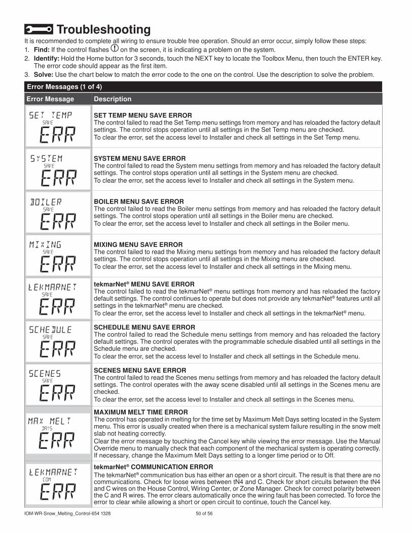
IOM-WR-Snow_Melting_Control-654328 50of56
TroubleshootingItisrecommendedtocompleteallwiringtoensuretroublefreeoperation.Shouldanerroroccur,simplyfollowthesesteps:. Find:Ifthecontrolflashes onthescreen,itisindicatingaproblemonthesystem.2.Identify:HoldtheHomebuttonfor3seconds,touchtheNEXTkeytolocatetheToolboxMenu,thentouchtheENTERkey.
Theerrorcodeshouldappearasthefirstitem.3.Solve:Usethechartbelowtomatchtheerrorcodetotheoneonthecontrol.Usethedescriptiontosolvetheproblem.
Error Message Description
SET TEMP MENU SAVE ERRORThecontrolfailedtoreadtheSetTempmenusettingsfrommemoryandhasreloadedthefactorydefaultsettings.ThecontrolstopsoperationuntilallsettingsintheSetTempmenuarechecked.Tocleartheerror,settheaccessleveltoInstallerandcheckallsettingsintheSetTempmenu.
SySTEM MENU SAVE ERRORThecontrolfailedtoreadtheSystemmenusettingsfrommemoryandhasreloadedthefactorydefaultsettings.ThecontrolstopsoperationuntilallsettingsintheSystemmenuarechecked.Tocleartheerror,settheaccessleveltoInstallerandcheckallsettingsintheSystemmenu.
BOILER MENU SAVE ERRORThecontrolfailedtoreadtheBoilermenusettingsfrommemoryandhasreloadedthefactorydefaultsettings.ThecontrolstopsoperationuntilallsettingsintheBoilermenuarechecked.Tocleartheerror,settheaccessleveltoInstallerandcheckallsettingsintheBoilermenu.
MIXING MENU SAVE ERRORThecontrolfailedtoreadtheMixingmenusettingsfrommemoryandhasreloadedthefactorydefaultsettings.ThecontrolstopsoperationuntilallsettingsintheMixingmenuarechecked.Tocleartheerror,settheaccessleveltoInstallerandcheckallsettingsintheMixingmenu.
tekmarNet® MENU SAVE ERRORThecontrolfailedtoreadthetekmarNet®menusettingsfrommemoryandhasreloadedthefactorydefaultsettings.ThecontrolcontinuestooperatebutdoesnotprovideanytekmarNet®featuresuntilallsettingsinthetekmarNet®menuarechecked.Tocleartheerror,settheaccessleveltoInstallerandcheckallsettingsinthetekmarNet®menu.
SCHEDULE MENU SAVE ERRORThecontrolfailedtoreadtheSchedulemenusettingsfrommemoryandhasreloadedthefactorydefaultsettings.ThecontroloperateswiththeprogrammablescheduledisableduntilallsettingsintheSchedulemenuarechecked.Tocleartheerror,settheaccessleveltoInstallerandcheckallsettingsintheSchedulemenu.
SCENES MENU SAVE ERRORThecontrolfailedtoreadtheScenesmenusettingsfrommemoryandhasreloadedthefactorydefaultsettings.ThecontroloperateswiththeawayscenedisableduntilallsettingsintheScenesmenuarechecked.Tocleartheerror,settheaccessleveltoInstallerandcheckallsettingsintheScenesmenu.
MAXIMUM MELT TIME ERRORThecontrolhasoperatedinmeltingforthetimesetbyMaximumMeltDayssettinglocatedintheSystemmenu.Thiserrorisusuallycreatedwhenthereisamechanicalsystemfailureresultinginthesnowmeltslabnotheatingcorrectly.CleartheerrormessagebytouchingtheCancelkeywhileviewingtheerrormessage.UsetheManualOverridemenutomanuallycheckthateachcomponentofthemechanicalsystemisoperatingcorrectly.Ifnecessary,changetheMaximumMeltDayssettingtoalongertimeperiodortoOff.
tekmarNet® COMMUNICATION ERRORThetekmarNet®communicationbushaseitheranopenorashortcircuit.Theresultisthattherearenocommunications.CheckforloosewiresbetweentN4andC.CheckforshortcircuitsbetweenthetN4andCwiresontheHouseControl,WiringCenter,orZoneManager.CheckforcorrectpolaritybetweentheCandRwires.Theerrorclearsautomaticallyoncethewiringfaulthasbeencorrected.Toforcetheerrortoclearwhileallowingashortoropencircuittocontinue,touchtheCancelkey.
Error Messages (1 of 4)

5of56 ©203WattsRadiant
Error Message Description
ADDRESS TAkEN ERRORTwodevices(thermostats,setpointcontrols,snowmeltingcontrols)havebeenmanuallysettothesameaddress.ThedevicecontinuestooperatewiththiserrorbutdoesnotcommunicatewiththetekmarNet®system.Toclearthiserror,selectanunusedtekmarNet®addressorselectautomaticaddressing.
SNOW ZONE TAkEN ERRORTwosnowmeltingcontrolshavebeenmanuallysettothesamesnowzonenumberandoneofthecontrolsisNOTsettoAppMode090.Thecontrolcontinuestooperatewiththiserror.Toclearthiserror,selectanunusedsnowzonenumberorsettheAppModeto090.
APP MODE 090 ERRORTwosnowmeltingcontrolshavebeenmanuallysettothesamesnowzonenumberandbothofthecontrolsaresettoAppMode090.Toclearthiserror,selectanunusedsnowzonenumberorsettheAppModetoanythingotherthan090.
TANDEM 090 ERRORTherearetwoSnow/IceSensors090installedinthezoneandtheothersnowmeltingcontrol’s090hasasensorproblem.LocatetheothersnowmeltingcontrolandnavigatetotheToolboxmenutodetermineandcorrecttheproblem.Thecontrolcontinuestooperatewiththiserror.
DEVICE LIMITMorethan24devices(thermostats,setpointcontrolsandsnowmeltingcontrols)havebeenconnectedtothetekmarNet®communicationbus.Tocleartheerror,removeandrelocatedevicestootheravailablebusesuntilthedevicecountis24orless.
OUTDOOR SENSOR SHORT CIRCUIT ERRORDuetoashortcircuit,thecontrolisunabletoreadtheOutdoorSensor070.Thecontrolcontinuestooperateandassumesanoutdoortemperatureof32°F(0°C).EnergysavingfeaturessuchasWarmWeatherShutDown(WWSD)andColdWeatherCutOut(CWCO)aredisabled.Checktheoutdoorsensorwireforshortcircuitsaccordingtothesensorinstallationmanual.Itmaybenecessarytoreplacetheoutdoorsensor.Oncetheerrorhasbeencorrected,theerrormessageautomaticallyclears.
OUTDOOR SENSOR OPEN CIRCUIT ERRORDuetoanopencircuit,thecontrolisunabletoreadtheOutdoorSensor070.Thecontrolcontinuestooperateandassumesanoutdoortemperatureof32°F(0°C).EnergysavingfeaturessuchasWarmWeatherShutDown(WWSD)andColdWeatherCutOut(CWCO)aredisabled.Checktheoutdoorsensorwireforopencircuitsaccordingtothesensorinstallationmanual.Itmaybenecessarytoreplacetheoutdoorsensor.Oncetheerrorhasbeencorrected,theerrormessageautomaticallyclears.
SUPPLy SENSOR SHORT CIRCUIT ERRORDuetoashortcircuit,thecontrolisunabletoreadtheSupplySensor082.WhensettoAppModeBoilerorMixingthecontrolstopsoperationanddoesnotprovideanyheat.WhensettoAppModePWMthecontrolcontinuesmeltingoridlingbutsupplypriorityoperationisnotavailable.Checkthesupplysensorwireforshortcircuitsaccordingtothesensorinstallationmanual.Itmaybenecessarytoreplacethesupplysensor.Oncetheerrorhasbeencorrected,theerrormessageautomaticallyclears.
SUPPLy SENSOR OPEN CIRCUIT ERRORDuetoanopencircuit,thecontrolisunabletoreadtheSupplySensor082.WhensettoAppModeBoilerorMixingthecontrolstopsoperationanddoesnotprovideanyheat.WhensettoAppModePWMthecontrolcontinuesmeltingoridlingbutsupplypriorityoperationisnotavailable.Checkthesupplysensorwireforopencircuitsaccordingtothesensorinstallationmanual.Itmaybenecessarytoreplacethesupplysensor.Oncetheerrorhasbeencorrected,theerrormessageautomaticallyclears.
Error Messages (2 of 4)

IOM-WR-Snow_Melting_Control-654328 52of56
Error Message Description
BOILER RETURN SENSOR SHORT CIRCUIT ERRORDuetoashortcircuit,thecontrolisunabletoreadtheBoilerReturnSensor082.Thecontrolcontinuesoperationbutdoesnotprovideanyboilerreturnprotection.Checktheboilerreturnsensorwireforshortcircuitsaccordingtothesensorinstallationmanual.Itmaybenecessarytoreplacetheboilerreturnsensor.Oncetheerrorhasbeencorrected,theerrormessageautomaticallyclears.
BOILER RETURN SENSOR OPEN CIRCUIT ERRORDuetoanopencircuit,thecontrolisunabletoreadtheBoilerReturnSensor082.Thecontrolcontinuesoperationbutdoesnotprovideanyboilerreturnprotection.Checktheboilerreturnsensorwireforopencircuitsaccordingtothesensorinstallationmanual.Itmaybenecessarytoreplacetheboilerreturnsensor.Oncetheerrorhasbeencorrected,theerrormessageautomaticallyclears.
SLAB SENSOR SHORT CIRCUIT ERRORDuetoashortcircuit,thecontrolisunabletoreadtheSlabSensor072.IdlingandStormaredisabledandenergysavingfeaturessuchasWarmWeatherShutDown(WWSD)andColdWeatherCutOut(CWCO)areoperateusingtheoutdoortemperatureonly.Checktheslabsensorwireforshortcircuitsaccordingtothesensorinstallationmanual.Itmaybenecessarytoreplacetheslabsensor.Oncetheerrorhasbeencorrected,theerrormessageautomaticallyclears.
SLAB SENSOR OPEN CIRCUIT ERRORDuetoanopencircuit,thecontrolisunabletoreadtheSlabSensor072.IdlingandStormaredisabledandenergysavingfeaturessuchasWarmWeatherShutDown(WWSD)andColdWeatherCutOut(CWCO)areoperateusingtheoutdoortemperatureonly.Checktheslabsensorwireforopencircuitsaccordingtothesensorinstallationmanual.Itmaybenecessarytoreplacetheslabsensor.Oncetheerrorhasbeencorrected,theerrormessageautomaticallyclears.Iftheslabsensorhasbeenintentionallyremoved,settheslabsensorsettingintheSystemmenutoOff.
yELLOW WIRE OPEN CIRCUIT ERRORDuetoanopencircuit,thecontrolisunabletoreadtheyellowwireconnectedtotheSnow/IceSensor090ortheSnowSensor095.Thecontrolcannolongerautomaticallydetectsnoworicebutmanualstartofthesnowmeltingsystemisstillavailable.ChecktheSnow/IceSensororSnowSensoryellowandblackwiresandanywiresplicesforopencircuitsaccordingtothesensorinstallationmanual.Itmaybenecessarytoreplacethesensor.Oncetheerrorhasbeencorrected,theerrormessageautomaticallyclears.
BLUE WIRE SHORT CIRCUIT ERRORDuetoashortcircuit,thecontrolisunabletoreadthebluewireconnectedtotheSnow/IceSensor090ortheSnowSensor095.Thecontrolcannolongerautomaticallydetectsnoworicebutmanualstartofthesnowmeltingsystemisstillavailable.FirstchecktheSnow/IceSensororSnowSensorfordirtordebris.Theringstructureofthesensormayneedcleaningwithhotsoapywaterandanylonbrush.Rinsewithwater.Secondly,checktheSnow/IceSensororSnowSensorblueandblackwiresandanywiresplicesforshortcircuitsaccordingtothesensorinstallationmanual.Itmaybenecessarytoreplacethesensor.Oncetheerrorhasbeencorrected,theerrormessageautomaticallyclears.
BLUE WIRE OPEN CIRCUIT ERRORDuetoanopencircuit,thecontrolisunabletoreadthebluewireconnectedtotheSnow/IceSensor090ortheSnowSensor095.Thecontrolcannolongerautomaticallydetectsnoworicebutmanualstartofthesnowmeltingsystemisstillavailable.ChecktheSnow/IceSensororSnowSensorblueandblackwiresandanywiresplicesforopencircuitsaccordingtothesensorinstallationmanual.Itmaybenecessarytoreplacethesensor.Oncetheerrorhasbeencorrected,theerrormessageautomaticallyclears.
BROWN WIRE SENSOR OPEN CIRCUIT ERRORDuetoanopencircuit,thecontrolisunabletoreadthebrownwireconnectedtotheSnow/IceSensor090.IdlingandStormisdisabledandenergysavingfeaturessuchasWarmWeatherShutDown(WWSD)andColdWeatherCutOut(CWCO)areoperateusingtheoutdoortemperatureonly.ChecktheSnow/IceSensorbrownandblackwiresforopencircuitsaccordingtothesensorinstallationmanual.Itmaybenecessarytoreplacethesensor.Oncetheerrorhasbeencorrected,theerrormessageautomaticallyclears.
Error Messages (3 of 4)

53of56 ©203WattsRadiant
Error Message Description
SNOW / ICE SENSOR ERRORThecontrolisunabletoproperlydetecttheSnow/IceSensor090.Thecontrolcannolongerautomaticallydetectsnoworicebutmanualstartofthesnowmeltingsystemisstillavailable.ChecktheSnow/IceSensorbrown,yellow,redandblackwiresaccordingtothesensorinstallationmanual.Itisimportanttocheckanycablesplicesforloosewiringconnections.Itmaybenecessarytoreplacethesensor.Oncetheerrorhasbeencorrected,theerrormessageautomaticallyclears.
SNOW SENSOR ERRORThecontrolisunabletoproperlydetecttheSnowSensor095.Thecontrolcannolongerautomaticallydetectsnowbutmanualstartofthesnowmeltingsystemisstillavailable.ChecktheSnowSensoryellow,redandblackwiresaccordingtothesensorinstallationmanual.Itmaybenecessarytoreplacethesensor.Oncetheerrorhasbeencorrected,theerrormessageautomaticallyclears.
SCHEDULE MASTER ERRORTwodevicesonthetekmarNet®systemhavebeensettothesameScheduleMasternumber.Thecontroloperatesaccordingtothelocalprogrammableschedulewhilethiserrorispresent.Tocleartheerror,selectadifferentScheduleMasternumber,setadifferentScheduleMembernumber,settheScheduletoZone,orsettheScheduletoNone.
SCHEDULE MEMBER ERRORThecontrolcannolongerdetectitsschedulemaster.Thecontroloperatesasiftheprogrammablescheduleisinidleoroffoperationwhilethiserrorispresent.Tocleartheerror,selectadifferentScheduleMembernumber,settheScheduletoZone,orsettheScheduletoNone.
ERROR AT THERMOSTATThereisanerroronadifferentthermostat,setpointcontrolorsnowmeltingcontrolconnectedtothetekmarNet®systemandnotonthiscontrol.0to24=ThereisanerroronathermostatorsetpointcontrolwiththistekmarNet®address.
ERROR AT THERMOSTATThereisanerroronadifferentthermostat,setpointcontrolorsnowmeltingcontrolconnectedtothetekmarNet®systemandnotonthiscontrol.b:0tob:24=ThereisanerroronathermostatorsetpointcontrolwiredtotheboilercommunicationbuswiththistekmarNet®address.
ERROR AT THERMOSTATThereisanerroronadifferentthermostat,setpointcontrolorsnowmeltingcontrolconnectedtothetekmarNet®systemandnotonthiscontrol.:0to:24=ThereisanerroronathermostatorsetpointcontrolwiredtocommunicationbuswiththistekmarNet®address.
ERROR AT THERMOSTATThereisanerroronadifferentthermostat,setpointcontrolorsnowmeltingcontrolconnectedtothetekmarNet®systemandnotonthiscontrol.2:0to2:24=Thereisanerroronathermostatorsetpointcontrolwiredtocommunicationbus2withthistekmarNet®address.
ERROR AT THERMOSTATThereisanerroronadifferentthermostat,setpointcontrolorsnowmeltingcontrolconnectedtothetekmarNet®systemandnotonthiscontrol.3:0to3:24=Thereisanerroronathermostatorsetpointcontrolwiredtothemix3buswiththistekmarNet®address.
ERROR AT SySTEM CONTROLThereisanerroronthetekmarNet®systemcontrolconnectedtothetekmarNet®systemandnotonthiscontrol.
Error Messages (4 of 4)
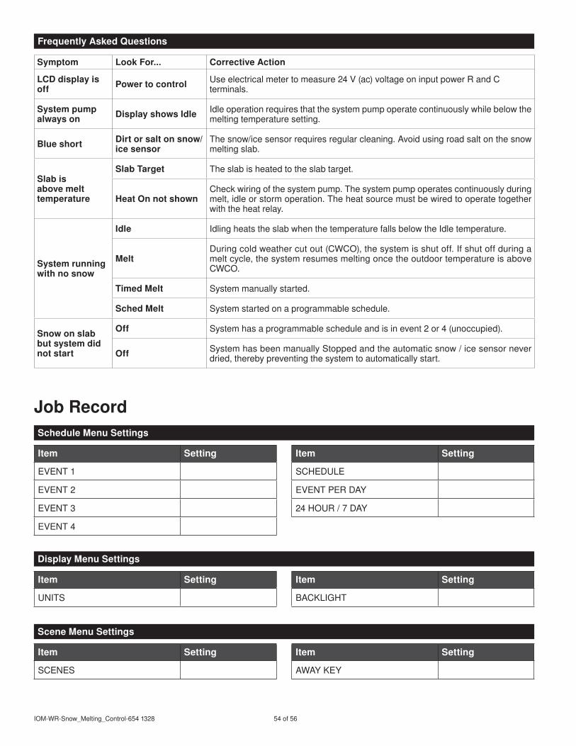
IOM-WR-Snow_Melting_Control-654328 54of56
Symptom Look For... Corrective Action
LCD display is off Power to control Useelectricalmetertomeasure24V(ac)voltageoninputpowerRandC
terminals.
System pump always on Display shows Idle Idleoperationrequiresthatthesystempumpoperatecontinuouslywhilebelowthe
meltingtemperaturesetting.
Blue short Dirt or salt on snow/ice sensor
Thesnow/icesensorrequiresregularcleaning.Avoidusingroadsaltonthesnowmeltingslab.
Slab is above melt temperature
Slab Target Theslabisheatedtotheslabtarget.
Heat On not shownCheckwiringofthesystempump.Thesystempumpoperatescontinuouslyduringmelt,idleorstormoperation.Theheatsourcemustbewiredtooperatetogetherwiththeheatrelay.
System running with no snow
Idle IdlingheatstheslabwhenthetemperaturefallsbelowtheIdletemperature.
MeltDuringcoldweathercutout(CWCO),thesystemisshutoff.Ifshutoffduringameltcycle,thesystemresumesmeltingoncetheoutdoortemperatureisaboveCWCO.
Timed Melt Systemmanuallystarted.
Sched Melt Systemstartedonaprogrammableschedule.
Snow on slab but system did not start
Off Systemhasaprogrammablescheduleandisinevent2or4(unoccupied).
Off SystemhasbeenmanuallyStoppedandtheautomaticsnow/icesensorneverdried,therebypreventingthesystemtoautomaticallystart.
Item Setting
EVENT
EVENT2
EVENT3
EVENT4
Item Setting
SCHEDULE
EVENTPERDAY
24HOUR/7DAY
Job Record
Item Setting
UNITS
Item Setting
BACKLIGHT
Item Setting
SCENES
Item Setting
AWAYKEY
Frequently Asked Questions
Schedule Menu Settings
Display Menu Settings
Scene Menu Settings

55of56 ©203WattsRadiant
Item Setting
MELTING
IDLING
STORM
MANUALMELTRUNTIME
ADDITIONALMELTTIME
Item Setting
STORMRUNTIME
WATERSENSITIVITY
WARMWEATHERSHUTDOWN
COLDWEATHERCUTOUT
Item Setting
APPLICATIONMODE
SNOW/ICESENSOR
SLABSENSOR
SLABPROTECTION
OUTDOORORBOILERRETURNSENSOR
Item Setting
ECONOMELT
tekmarNet®SYSTEMPUMP
AUXILIARYRELAY
MAXIMUMMELTTIME
Item Setting
BOILERTYPE
BOILERMODULATIONTYPE
BOILERMINIMUMMODULATION
BOILERMODULATIONDELAY
Item Setting
BOILERMOTORSPEED
BOILERDIFFERENTIAL
BOILERMINIMUM
Item Setting
MIXTYPE
MIXMOTORSPEED
Item Setting
MIXMAXIMUM
Item Setting
ADDRESS
SNOWZONE
TRACKZONE
MELTGROUP
Item Setting
STORMGROUP
PRIORITY
LOCALNETWORKGROUP
WARNING:ThisproductcontainschemicalsknowntotheStateofCaliforniatocausecancerandbirthdefectsorotherreproductiveharm.Formoreinformation:www.watts.com/prop65
Set Temp Menu Settings
System Menu Settings
Boiler Menu Settings
Mixing Menu Settings
tekmarNet® Menu Settings
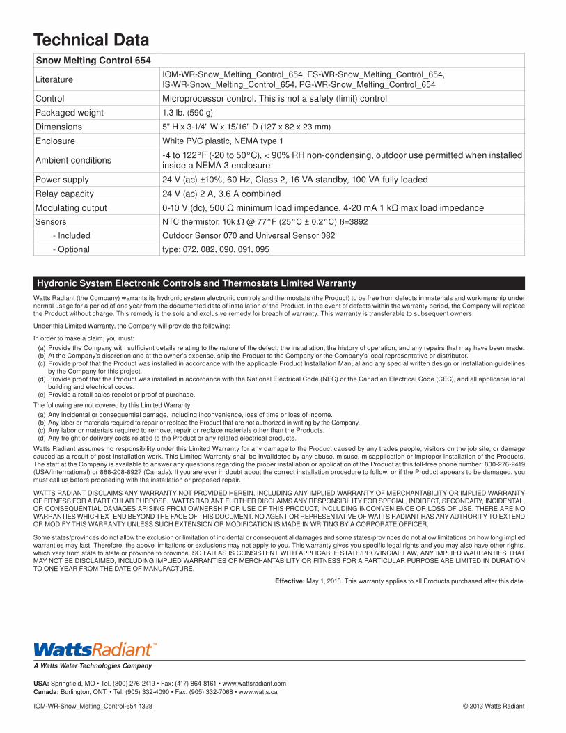
A Watts Water Technologies Company
USA:Springfield,MO•Tel.(800)276-249•Fax:(47)864-86•www.wattsradiant.comCanada:Burlington,ONT.•Tel.(905)332-4090•Fax:(905)332-7068•www.watts.ca
IOM-WR-Snow_Melting_Control-654328 ©203WattsRadiant
Hydronic System Electronic Controls and Thermostats Limited WarrantyWattsRadiant(theCompany)warrantsitshydronicsystemelectroniccontrolsandthermostats(theProduct)tobefreefromdefectsinmaterialsandworkmanshipundernormalusageforaperiodofoneyearfromthedocumenteddateofinstallationoftheProduct.Intheeventofdefectswithinthewarrantyperiod,theCompanywillreplacetheProductwithoutcharge.Thisremedyisthesoleandexclusiveremedyforbreachofwarranty.Thiswarrantyistransferabletosubsequentowners.
UnderthisLimitedWarranty,theCompanywillprovidethefollowing:
Inordertomakeaclaim,youmust:(a)ProvidetheCompanywithsufficientdetailsrelatingtothenatureofthedefect,theinstallation,thehistoryofoperation,andanyrepairsthatmayhavebeenmade.(b)AttheCompany’sdiscretionandattheowner’sexpense,shiptheProducttotheCompanyortheCompany’slocalrepresentativeordistributor.(c) ProvideproofthattheProductwasinstalledinaccordancewiththeapplicableProductInstallationManualandanyspecialwrittendesignorinstallationguidelines
bytheCompanyforthisproject.(d)ProvideproofthattheProductwasinstalledinaccordancewiththeNationalElectricalCode(NEC)ortheCanadianElectricalCode(CEC),andallapplicablelocal
buildingandelectricalcodes.(e)Providearetailsalesreceiptorproofofpurchase.
ThefollowingarenotcoveredbythisLimitedWarranty:(a)Anyincidentalorconsequentialdamage,includinginconvenience,lossoftimeorlossofincome.(b)AnylaborormaterialsrequiredtorepairorreplacetheProductthatarenotauthorizedinwritingbytheCompany.(c) Anylaborormaterialsrequiredtoremove,repairorreplacematerialsotherthantheProducts.(d)AnyfreightordeliverycostsrelatedtotheProductoranyrelatedelectricalproducts.
WattsRadiantassumesnoresponsibilityunderthisLimitedWarrantyforanydamagetotheProductcausedbyanytradespeople,visitorsonthejobsite,ordamagecausedasaresultofpost-installationwork.ThisLimitedWarrantyshallbeinvalidatedbyanyabuse,misuse,misapplicationorimproperinstallationoftheProducts.ThestaffattheCompanyisavailabletoansweranyquestionsregardingtheproperinstallationorapplicationoftheProductatthistoll-freephonenumber:800-276-249(USA/International)or888-208-8927(Canada).Ifyouareeverindoubtaboutthecorrectinstallationproceduretofollow,oriftheProductappearstobedamaged,youmustcallusbeforeproceedingwiththeinstallationorproposedrepair.
WATTSRADIANTDISCLAIMSANYWARRANTYNOTPROVIDEDHEREIN,INCLUDINGANYIMPLIEDWARRANTYOFMERCHANTABILITYORIMPLIEDWARRANTYOFFITNESSFORAPARTICULARPURPOSE.WATTSRADIANTFURTHERDISCLAIMSANYRESPONSIBILITYFORSPECIAL,INDIRECT,SECONDARY,INCIDENTAL,ORCONSEQUENTIALDAMAGESARISINGFROMOWNERSHIPORUSEOFTHISPRODUCT,INCLUDINGINCONVENIENCEORLOSSOFUSE.THEREARENOWARRANTIESWHICHEXTENDBEYONDTHEFACEOFTHISDOCUMENT.NOAGENTORREPRESENTATIVEOFWATTSRADIANTHASANYAUTHORITYTOEXTENDORMODIFYTHISWARRANTYUNLESSSUCHEXTENSIONORMODIFICATIONISMADEINWRITINGBYACORPORATEOFFICER.
Somestates/provincesdonotallowtheexclusionorlimitationofincidentalorconsequentialdamagesandsomestates/provincesdonotallowlimitationsonhowlongimpliedwarrantiesmaylast.Therefore,theabovelimitationsorexclusionsmaynotapplytoyou.Thiswarrantygivesyouspecificlegalrightsandyoumayalsohaveotherrights,whichvaryfromstatetostateorprovincetoprovince.SOFARASISCONSISTENTWITHAPPLICABLESTATE/PROVINCIALLAW,ANYIMPLIEDWARRANTIESTHATMAYNOTBEDISCLAIMED,INCLUDINGIMPLIEDWARRANTIESOFMERCHANTABILITYORFITNESSFORAPARTICULARPURPOSEARELIMITEDINDURATIONTOONEYEARFROMTHEDATEOFMANUFACTURE.
Effective: May,203.ThiswarrantyappliestoallProductspurchasedafterthisdate.
Technical DataSnow Melting Control 654
Literature IOM-WR-Snow_Melting_Control_654,ES-WR-Snow_Melting_Control_654,IS-WR-Snow_Melting_Control_654,PG-WR-Snow_Melting_Control_654
Control Microprocessorcontrol.Thisisnotasafety(limit)control
Packagedweight .3lb.(590g)
Dimensions 5"Hx3-/4"Wx5/6"D(27x82x23mm)
Enclosure WhitePVCplastic,NEMAtype
Ambientconditions -4to22°F(-20to50°C),<90%RHnon-condensing,outdoorusepermittedwheninstalledinsideaNEMA3enclosure
Powersupply 24V(ac)±0%,60Hz,Class2,6VAstandby,00VAfullyloaded
Relaycapacity 24V(ac)2A,3.6Acombined
Modulatingoutput 0-0V(dc),500Ωminimumloadimpedance,4-20mAkΩmaxloadimpedanceSensors NTCthermistor,0k @77°F(25°C±0.2°C)ß=3892
-Included OutdoorSensor070andUniversalSensor082
-Optional type:072,082,090,09,095