installation & operation manual models: 80 - 285 starting...
TRANSCRIPT

Installation & Operation Manual
Models: 80 - 285
Starting Serial #H07H10040039
This manual must only be used by aqualified heating installer / servicetechnician. Read all instructions,including this manual and theKnight Boiler Service Manual, beforeinstalling. Perform steps in the ordergiven. Failure to comply could resultin severe personal injury, death, orsubstantial property damage.
� WARNING
Save this manual for future reference.
2
Hazard definitionsThe following defined terms are used throughout this manual to bring attention to the presence of hazards of various risk levels orto important information concerning the life of the product.
� DANGER
� WARNING
� CAUTION
CAUTION
NOTICE
DANGER indicates an imminently hazardous situation which, if not avoided, will result in death or seriousinjury.
WARNING indicates a potentially hazardous situation which, if not avoided, could result in death or seriousinjury.
CAUTION indicates a potentially hazardous situation which, if not avoided, may result in minor or moderateinjury.
CAUTION used without the safety alert symbol indicates a potentially hazardous situation which, if notavoided, may result in property damage.
NOTICE indicates special instructions on installation, operation, or maintenance that are important but notrelated to personal injury or property damage.
HAZARD DEFINITIONS . . . . . . . . . . . . . . . . . . . . . . . . . . 2
PLEASE READ BEFORE PROCEEDING . . . . . . . . . . . . 3
THE KNIGHT BOILER -- HOW IT WORKS . . . . . . . . . . . 4
RATINGS . . . . . . . . . . . . . . . . . . . . . . . . . . . . . . . . . . . . . . 7
1. DETERMINE BOILER LOCATION
Provide Clearances . . . . . . . . . . . . . . . . . . . . . . . . . . . . . . 8
Provide Air Openings to Room . . . . . . . . . . . . . . . . . . . . 10
Flooring and Foundation . . . . . . . . . . . . . . . . . . . . . . . . 10
Residential Garage Installation . . . . . . . . . . . . . . . . . . . . 10
Vent and Air Piping . . . . . . . . . . . . . . . . . . . . . . . . . . . . . 10
Prevent Combustion Air Contamination . . . . . . . . . . . . . . 10
Corrosive Contaminants and Sources . . . . . . . . . . . . . . . 11
Removing a Boiler from Existing Common Vent . . . . . . . 11
2. PREPARE BOILER
Remove Boiler from Wood Pallet . . . . . . . . . . . . . . . . . . 12
Gas Conversions . . . . . . . . . . . . . . . . . . . . . . . . . . . . . . . 12
Leveling the Boiler . . . . . . . . . . . . . . . . . . . . . . . . . . . 12
3. GENERAL VENTING
Direct Venting Options . . . . . . . . . . . . . . . . . . . . . . . . . . . 13
Install Vent and Combustion Air Piping . . . . . . . . . . . . . . 14
Vent and Air Piping Materials . . . . . . . . . . . . . . . . . . . 14
Requirements for Installation in Canada . . . . . . . . . . . . . 14
Air Intake/Vent Connections . . . . . . . . . . . . . . . . . . . . . . 15
Min./Max. Combustion Air & Vent Piping Lengths . . . . . . 15
Removing from Existing Vent . . . . . . . . . . . . . . . . . . . . . 16
Vent and Air Piping . . . . . . . . . . . . . . . . . . . . . . . . . . . . . 16
4. SIDEWALL DIRECT VENTING
Vent/Air Termination - Sidewall . . . . . . . . . . . . . . . . . . . . 17-20
Determine Location . . . . . . . . . . . . . . . . . . . . . . . . . . 17-18
Prepare Wall Penetrations . . . . . . . . . . . . . . . . . . . . . 19
Termination and Fittings . . . . . . . . . . . . . . . . . . . . . . . 19
Multiple Vent/Air Terminations . . . . . . . . . . . . . . . . . . . . . 20
Sidewall Termination - Optional Concentric Vent . . . . . . 21-23
5. VERTICAL DIRECT VENTING
Vent/Air Termination - Vertical . . . . . . . . . . . . . . . . . . . . . 24-25
Determine Location . . . . . . . . . . . . . . . . . . . . . . . . . . 24
Prepare Roof Penetrations . . . . . . . . . . . . . . . . . . . . . 25
Termination and Fittings . . . . . . . . . . . . . . . . . . . . . . . . . 25
Multiple Vent/Air Terminations . . . . . . . . . . . . . . . . . . . . . 25
Vertical Termination - Optional Concentric Vent . . . . . . . 26-27
6. HYDRONIC PIPING
System Water Piping Methods . . . . . . . . . . . . . . . . . . . . 28
Low Water Cutoff Device . . . . . . . . . . . . . . . . . . . . . . . . . 28
Chilled Water System . . . . . . . . . . . . . . . . . . . . . . . . . . . 28
Freeze Protection . . . . . . . . . . . . . . . . . . . . . . . . . . . . . . 28
General Piping Information . . . . . . . . . . . . . . . . . . . . . . . 28
Relief Valve / T & P Installation . . . . . . . . . . . . . . . . . . . . 28-29
Circulator Sizing . . . . . . . . . . . . . . . . . . . . . . . . . . . . . . . 29
Near Boiler Piping Connections . . . . . . . . . . . . . . . . . . . 29
Near Boiler Piping Components . . . . . . . . . . . . . . . . . . . 31
7. GAS CONNECTIONS
Connecting Gas Supply Piping . . . . . . . . . . . . . . . . . . . . 38
Natural Gas . . . . . . . . . . . . . . . . . . . . . . . . . . . . . . . . . . . 39
Pipe Sizing for Natural Gas . . . . . . . . . . . . . . . . . . . . 39
Natural Gas Supply Pressure Requirements . . . . . . . 39
Propane Gas . . . . . . . . . . . . . . . . . . . . . . . . . . . . . . . . . . 39
Pipe Sizing for Propane Gas . . . . . . . . . . . . . . . . . . . 39
Propane Supply Pressure Requirements . . . . . . . . . . 39
Check Inlet Gas Supply . . . . . . . . . . . . . . . . . . . . . . . . . . 40
Gas Pressure . . . . . . . . . . . . . . . . . . . . . . . . . . . . . . . . . . 41
Gas Valve Replacement . . . . . . . . . . . . . . . . . . . . . . . . . 41
8. FIELD WIRING
Line Voltage Connections . . . . . . . . . . . . . . . . . . . . . . . . 42
Low Voltage Connections . . . . . . . . . . . . . . . . . . . . . . . . 43
Wiring of the Cascade . . . . . . . . . . . . . . . . . . . . . . . . . . . 44
9. CONDENSATE DISPOSAL
Condensate Drain . . . . . . . . . . . . . . . . . . . . . . . . . . . . . . 46
10. STARTUP . . . . . . . . . . . . . . . . . . . . . . . . . . . . . . . . . 47-52
11. OPERATING INFORMATION
General . . . . . . . . . . . . . . . . . . . . . . . . . . . . . . . . . . . . . . 53
Cascade . . . . . . . . . . . . . . . . . . . . . . . . . . . . . . . . . . . . . . 55-56
Sequence of Operation . . . . . . . . . . . . . . . . . . . . . . . . . . 57-58
Knight Boiler Control Module . . . . . . . . . . . . . . . . . . . . . . 59-60
Status Display Screens . . . . . . . . . . . . . . . . . . . . . . . . . . 61-64
12. MAINTENANCE
Maintenance and Annual Startup . . . . . . . . . . . . . . . . . . 65-69
13. DIAGRAMS
Ladder Diagram . . . . . . . . . . . . . . . . . . . . . . . . . . . . . . . . 70
Wiring Diagram . . . . . . . . . . . . . . . . . . . . . . . . . . . . . . . . 71
Revision Notes . . . . . . . . . . . . . . . . . . . . . . . . . Back Cover
Contents
Installation & Operation Manual
3
Please read before proceedingInstaller – Read all instructions,including this manual and the KnightBoiler Service Manual, before installing.Perform steps in the order given.
User – This manual is for use only by aqualified heating installer/servicetechnician. Refer to the User’sInformation Manual for your reference.
Have this boiler serviced/inspected by aqualified service technician, at leastannually.
Failure to comply with the above couldresult in severe personal injury, death orsubstantial property damage.
Failure to adhere to the guidelines on thispage can result in severe personal injury,death, or substantial property damage.
When servicing boiler –
• To avoid electric shock, disconnect electrical supply before performing maintenance.
• To avoid severe burns, allow boiler to cool before performing maintenance.
Boiler operation –
• Do not block flow of combustion or ventilation air to the boiler.
• Should overheating occur or gas supply fail to shut off, do not turn off or disconnect electrical supply to circulator. Instead, shut off the gas supply at a location external to the appliance.
• Do not use this boiler if any part has been under water. The possible damage to a flooded appliance can be extensive and present numerous safety hazards. Any appliance that has been under water must be replaced.
Boiler water –
• Thoroughly flush the system (without boiler connected) to remove sediment. The high-efficiency heat exchanger can be damaged by build-up or corrosion due to sediment.
• Do not use petroleum-based cleaning or sealing compounds in the boiler system. Gaskets and seals in the system may be damaged. This can result in substantial property damage.
• Do not use “homemade cures” or “boiler patent medicines”. Serious damage to the boiler, personnel, and/or property may result.
• Continual fresh make-up water will reduce boiler life. Mineral buildup in the heat exchanger reduces heat transfer, overheats the stainless steel heat exchanger, and causes failure. Addition of oxygen carried in by makeup water can cause internal corrosion in system components. Leaks in boiler or piping must be repaired at once to prevent makeup water.
Freeze protection fluids –
• NEVER use automotive antifreeze. Use only inhibited propylene glycol solutions, which are specifically formulated for hydronic systems. Ethylene glycol is toxic and can attack gaskets and seals used in hydronic systems.
When calling or writing about the boiler –Please have the boiler model and serialnumber from the boiler rating plate.
Consider piping and installation whendetermining boiler location.
Any claims for damage or shortage inshipment must be filed immediatelyagainst the transportation company bythe consignee.
Factory warranty (shipped with unit)does not apply to units improperlyinstalled or improperly operated.
If the information in this manual is notfollowed exactly, a fire or explosion mayresult causing property damage, personalinjury or loss of life.
This appliance MUST NOT be installedin any location where gasoline orflammable vapors are likely to be present.
WHAT TO DO IF YOU SMELL GAS
• Do not try to light any appliance.• Do not touch any electric switch; do
not use any phone in your building.• Immediately call your gas supplier
from a near by phone. Follow the gas supplier’s instructions.
• If you cannot reach your gas supplier, call the fire department.
• Installation and service must be performed by a qualified installer, service agency, or the gas supplier.
� WARNING
NOTICE
� WARNING
� WARNING
Installation & Operation Manual
4
The Knight Boiler - How it works...1. Stainless steel heat exchanger
Allows system water to flow through specially designed coils for maximum heat transfer, while providing protection against flue gas corrosion. The coils are encased in a jacket that contains the combustion process.
2. Heat exchanger access coverAllows access to the combustion side of the heat exchanger coils.
3. BlowerThe blower pulls in air and gas through the venturi (item 5). Air and gas mix inside the blower and are pushed into the burner, where they burn inside the combustion chamber.
4. Gas valveThe gas valve senses the negative pressure created by the blower, allowing gas to flow only if the gas valve is powered and combustion air is flowing.
5. VenturiThe venturi controls air and gas flow into the burner.
6. Flue gas sensorThis sensor monitors the flue gas exit temperature. The control module will modulate and shut down the boiler if flue gas temperature gets too hot. This protects the flue pipe from overheating.
7. Boiler outlet temperature sensorThis sensor monitors boiler outlet water temperature (system supply). If selected as the controlling sensor, the control module adjusts boiler firing rate so the outlet temperature is correct.
8. Boiler inlet temperature sensorThis sensor monitors return water temperature (system return). If selected as the controlling sensor, the control module adjusts the boiler firing rate so the inlet temperature is correct.
9. Temperature and pressure gauge (field installed, not shown)Monitors the outlet temperature of the boiler as well as the system water pressure.
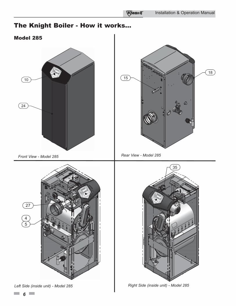
10. Electronic displayThe electronic display consists of 7 buttons and a dual line 32-character liquid crystal display.
11. Flue pipe adapterAllows for the connection of the PVC vent pipe system to the boiler.
12. Burner (not shown)Made with metal fiber and stainless steel construction, the burner uses pre-mixed air and gas and provides a wide range of firing rates.
13. Water outlet (system supply)NPT water connection that supplies hot water to the system, either 1" or 1-1/4", depending on the model.
14. Water inlet (system return)
NPT water connection that returns water from the system to the heat exchanger, either 1" or 1-1/4", depending on the model.
15. Gas connection pipeThreaded pipe connection, either 1/2" or 3/4", depending on the model. This pipe should be connected to the incoming gas supply for the purpose of delivering gas to the boiler.
16. SMART Control ModuleThe SMART Control responds to internal and external signals and controls the blower, gas valve, and pumps to meet the heating demand.
17. Automatic air ventDesigned to remove trapped air from the heat exchanger coils.
18. Air intake adapterAllows for the connection of the PVC air intake pipe to the boiler.
19. High voltage junction boxThe junction box contains the connection points for the line voltage power and all pumps.
20. Boiler drain portLocation from which the heat exchanger can be drained.
21. Low voltage connection boardThe connection board is used to connect external low voltage devices.
22. Low voltage wiring connections (knockouts)Conduit connection points for the low voltage connection board.
23. Condensate drain connectionConnects the condensate drain line to a 1/2" PVC union.
24. Access cover - frontProvides access to the gas train and the heat exchanger.
25. Ignition electrodeProvides direct spark for igniting the burner.
26. Flame inspection windowThe quartz glass window provides a view of the burner surface and flame.
27. Gas shutoff valveManual valve used to isolate the gas valve from the gas supply.
28. High limit sensorDevice that monitors the outlet water temperature. If the temperature exceeds its setting, it will break the control circuit, shutting the boiler down.
29. Relief valveProtects the heat exchanger from an over pressure condition. The relief valve may be set at 30 psi.
30. Flame sensorUsed by the control module to detect the presence of burner flame.
31. Line voltage wiring connections (knockouts)Conduit connection points for the high voltage junction box.
32. Top panelRemovable panel to gain access to the internal components.
33. Power switchTurns 120 VAC ON/OFF to the boiler.
34. Leveling legsUsed to allow the heat exchanger to be leveled. This is needed for the proper draining of the condensate from the combustion chamber.
35. Air pressure switchThe air pressure switch detects blocked inlet conditions.
Installation & Operation Manual
5
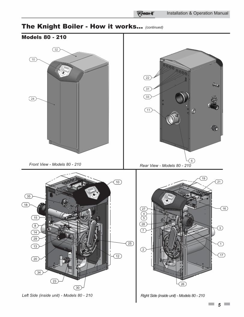
Front View - Models 80 - 210
23
8
10
13
14
15
18
2012
25
30
29
34
35
Left Side (inside unit) - Models 80 - 210
1
3
4
2
27
7
28
26
2119
16
17
5
Right Side (inside unit) - Models 80 - 210
The Knight Boiler - How it works... (continued)
Rear View - Models 80 - 210
Models 80 - 210
Installation & Operation Manual
6
The Knight Boiler - How it works...
1518
Model 285
Left Side (inside unit) - Model 285 Right Side (inside unit) - Model 285
Front View - Model 285 Rear View - Model 285
32
24
10
27
54
35
Installation & Operation Manual
7
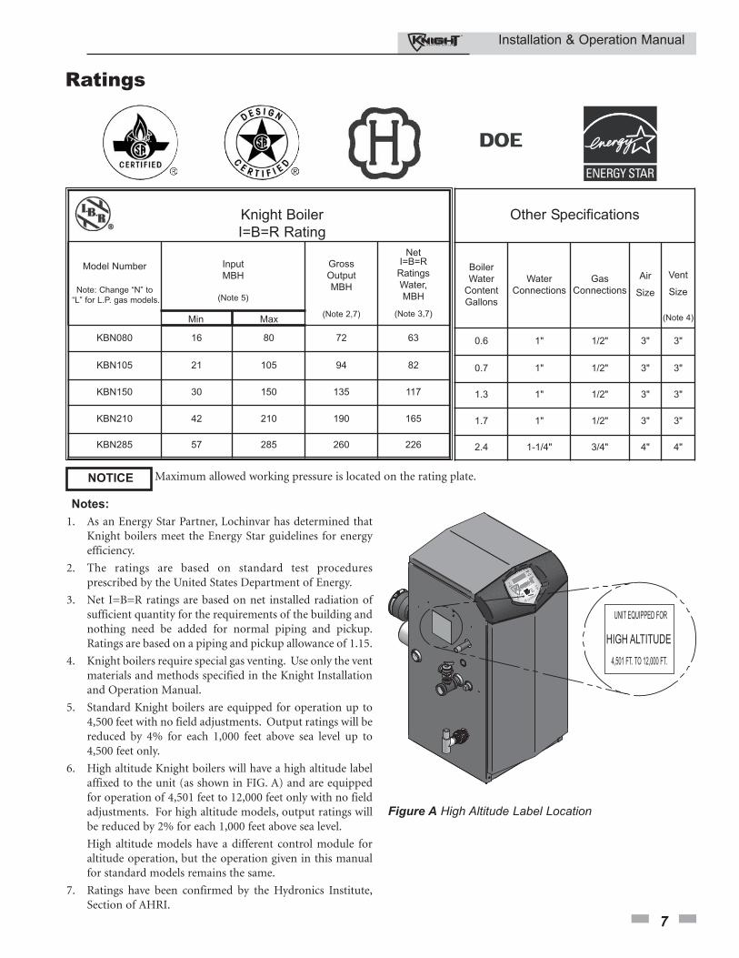
Ratings
Notes:
1. As an Energy Star Partner, Lochinvar has determined thatKnight boilers meet the Energy Star guidelines for energyefficiency.
2. The ratings are based on standard test proceduresprescribed by the United States Department of Energy.
3. Net I=B=R ratings are based on net installed radiation ofsufficient quantity for the requirements of the building andnothing need be added for normal piping and pickup.Ratings are based on a piping and pickup allowance of 1.15.
4. Knight boilers require special gas venting. Use only the ventmaterials and methods specified in the Knight Installationand Operation Manual.
5. Standard Knight boilers are equipped for operation up to4,500 feet with no field adjustments. Output ratings will bereduced by 4% for each 1,000 feet above sea level up to4,500 feet only.
6. High altitude Knight boilers will have a high altitude labelaffixed to the unit (as shown in FIG. A) and are equippedfor operation of 4,501 feet to 12,000 feet only with no fieldadjustments. For high altitude models, output ratings willbe reduced by 2% for each 1,000 feet above sea level.
High altitude models have a different control module foraltitude operation, but the operation given in this manualfor standard models remains the same.
7. Ratings have been confirmed by the Hydronics Institute,Section of AHRI.
Maximum allowed working pressure is located on the rating plate.NOTICE
Knight Boiler
I=B=R Rating
Model Number
Note: Change “N” to
“L” for L.P. gas models.
Input
MBH
(Note 5)
Min Max
Gross
Output
MBH
(Note 2,7)
NetI=B=R
Ratings
Water,
MBH
(Note 3,7)
KBN080 16 80 72 63
KBN105 21 105 94 82
KBN150 30 150 135 117
KBN210 42 210 190 165
KBN285 57 285 260 226
Other Specifications
Boiler
Water
Content
Gallons
Water
Connections
Gas
Connections
Air
Size
Vent
Size
(Note 4)
0.6 1" 1/2" 3" 3"
0.7 1" 1/2" 3" 3"
1.3 1" 1/2" 3" 3"
1.7 1" 1/2" 3" 3"
2.4 1-1/4" 3/4" 4" 4"
Figure A High Altitude Label Location
UNIT EQUIPPED FOR
4,501 FT. TO 12,000 FT.
HIGH ALTITUDE
Installation & Operation Manual
8
The Knight boiler gas manifold andcontrols met safe lighting and otherperformance criteria when the boilerunderwent tests specified in ANSI Z21.13– latest edition.
Failure to keep boiler area clear and free ofcombustible materials, gasoline, and otherflammable liquids and vapors can result insevere personal injury, death, orsubstantial property damage.
Installation must comply with:
• Local, state, provincial, and national codes, laws,regulations, and ordinances.
• National Fuel Gas Code, ANSI Z223.1 – latest edition.• Standard for Controls and Safety Devices for
Automatically Fired Boilers, ANSI/ASME CSD-1, whenrequired.
• National Electrical Code.• For Canada only: B149.1 Installation Code, CSA C22.1
Canadian Electrical Code Part 1 and any local codes.
Before locating the boiler, check:
1. Check for nearby connection to:• System water piping• Venting connections• Gas supply piping• Electrical power
2. Locate the appliance so that if water connections should leak, water damage will not occur. When such locations cannot be avoided, it is recommended that a suitable drain pan, adequately drained, be installed under the appliance. The pan must not restrict combustion air flow. Under no circumstances is the manufacturer to be held responsible for water damage in connection with this appliance, or any of its components.
3. Check area around the boiler. Remove any combustible materials, gasoline and other flammable liquids.
4. The Knight boiler must be installed so that gas controlsystem components are protected from dripping orspraying water or rain during operation or service.
5. If a new boiler will replace an existing boiler, check forand correct system problems, such as:• System leaks causing oxygen corrosion or heat
exchanger cracks from hard water deposits.• Incorrectly-sized expansion tank.• Lack of freeze protection in boiler water causing system
and boiler to freeze and leak.
� WARNINGThis appliance is certified as an indoorappliance. Do not install the applianceoutdoors or locate where the appliance willbe exposed to freezing temperatures or totemperatures that exceed 100°F.
Failure to install the appliance indoorscould result in severe personal injury,death, or substantial property damage.
Provide clearances:
Clearances from combustible materials
1. Hot water pipes—at least 1" from combustible materials.2. Vent pipe – at least 1" from combustible materials.3. See FIG.’s 1-1 and 1-2 on page 9 for other clearance
minimums.
Clearances for service access
1. See FIG.’s 1-1 and 1-2 on page 9 for recommended service clearances. If you do not provide the minimum clearances shown, it may not be possible to service the boiler without removing it from the space.
Closet and alcove installations
This appliance requires a special ventingsystem. The vent connection to theappliance must be made with the starterCPVC pipe section provided with theappliance. The field provided vent fittingsmust be cemented to the CPVC pipesection. Use only the vent materials,primer and cement specified in thismanual to make the vent connections.Failure to follow this warning could resultin fire, personal injury, or death.
For closet and alcove installations asshown in FIG.’s 1-1 and 1-2, CPVC ventmaterial must be used inside the structure.The ventilating air openings shown inFIG.’s 1-1 and 1-2 are required for thisarrangement. Failure to follow thiswarning could result in fire, personalinjury, or death.
� WARNING
� WARNING
NOTICE
� WARNING
1 Determine boiler location
A closet is any room the boiler is installed in which is less than67 cubic feet for KBN080 and KBN105 models, 86 cubic feetfor KBN150 models, 107 cubic feet for KBN210 models,and 120 cubic feet for KBN285 models.
An alcove is any room which meets the criteria for a closetwith the exception that it does not have a door.
Example: Room dimensions = 4 feet long, 4 feet wide, and9 foot ceiling = 4 x 4 x 9 = 144 cubic feet. This would beconsidered a closet for a Knight Boiler.
Installation & Operation Manual
9
1 Determine boiler location (continued)
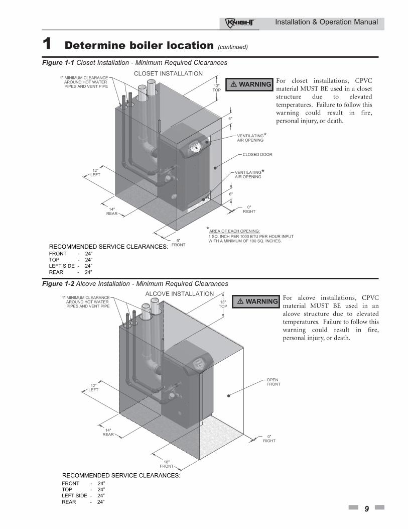
RECOMMENDED SERVICE CLEARANCES:
FRONT - 24”
TOP - 24”
LEFT SIDE - 24”
REAR - 24”
Figure 1-2 Alcove Installation - Minimum Required Clearances
RECOMMENDED SERVICE CLEARANCES:FRONT - 24”
TOP - 24”
LEFT SIDE - 24”
REAR - 24”
Figure 1-1 Closet Installation - Minimum Required Clearances
� WARNINGFor closet installations, CPVCmaterial MUST BE used in a closetstructure due to elevatedtemperatures. Failure to follow thiswarning could result in fire,personal injury, or death.
� WARNINGFor alcove installations, CPVCmaterial MUST BE used in analcove structure due to elevatedtemperatures. Failure to follow thiswarning could result in fire,personal injury, or death.
Installation & Operation Manual
10
1 Determine boiler locationProvide air openings to room:
Knight boiler alone in boiler room
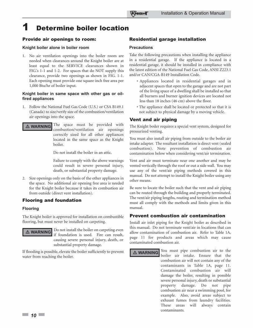
1. No air ventilation openings into the boiler room areneeded when clearances around the Knight boiler are atleast equal to the SERVICE clearances shown inFIG.’s 1-1 and 1-2. For spaces that do NOT supply thisclearance, provide two openings as shown in FIG. 1-1.Each opening must provide one square inch free area per1,000 Btu/hr of boiler input.
Knight boiler in same space with other gas or oil-
fired appliances
1. Follow the National Fuel Gas Code (U.S.) or CSA B149.1(Canada) to size/verify size of the combustion/ventilationair openings into the space.
The space must be provided withcombustion/ventilation air openingscorrectly sized for all other applianceslocated in the same space as the Knightboiler.
Do not install the boiler in an attic.
Failure to comply with the above warningscould result in severe personal injury,death, or substantial property damage.
2. Size openings only on the basis of the other appliances inthe space. No additional air opening free area is neededfor the Knight boiler because it takes its combustion airfrom outside (direct vent installation).
Do not install the boiler on carpeting evenif foundation is used. Fire can result,causing severe personal injury, death, orsubstantial property damage.
If flooding is possible, elevate the boiler sufficiently to preventwater from reaching the boiler.
Flooring and foundation
Flooring
The Knight boiler is approved for installation on combustibleflooring, but must never be installed on carpeting.
Residential garage installation
Precautions
Take the following precautions when installing the appliancein a residential garage. If the appliance is located in aresidential garage, it should be installed in compliance withthe latest edition of the National Fuel Gas Code, ANSI Z223.1and/or CAN/CGA-B149 Installation Code.
• Appliances located in residential garages and in adjacent spaces that open to the garage and are not part of the living space of a dwelling shall be installed so that all burners and burner ignition devices are located not less than 18 inches (46 cm) above the floor.
• The appliance shall be located or protected so that it is not subject to physical damage by a moving vehicle.
Vent and air pipingThe Knight boiler requires a special vent system, designed forpressurized venting.
You must also install air piping from outside to the boiler airintake adapter. The resultant installation is direct vent (sealedcombustion). Note prevention of combustion aircontamination below when considering vent/air termination.
Vent and air must terminate near one another and may bevented vertically through the roof or out a side wall. You mayuse any of the vent/air piping methods covered in thismanual. Do not attempt to install the Knight boiler using anyother means.
Be sure to locate the boiler such that the vent and air pipingcan be routed through the building and properly terminated.The vent/air piping lengths, routing and termination methodmust all comply with the methods and limits given in thismanual.
Prevent combustion air contaminationInstall air inlet piping for the Knight boiler as described inthis manual. Do not terminate vent/air in locations that canallow contamination of combustion air. Refer to Table 1A,page 11 for products and areas which may causecontaminated combustion air.
You must pipe combustion air to theboiler air intake. Ensure that thecombustion air will not contain any of thecontaminants in Table 1A, page 11.Contaminated combustion air willdamage the boiler, resulting in possiblesevere personal injury, death or substantialproperty damage. Do not pipecombustion air near a swimming pool, forexample. Also, avoid areas subject toexhaust fumes from laundry facilities.These areas will always containcontaminants.
� WARNING
� WARNING
� WARNING
Installation & Operation Manual
11
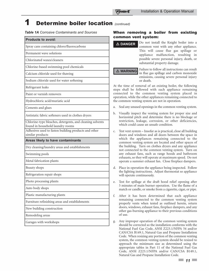
Products to avoid:
Spray cans containing chloro/fluorocarbons
Permanent wave solutions
Chlorinated waxes/cleaners
Chlorine-based swimming pool chemicals
Calcium chloride used for thawing
Sodium chloride used for water softening
Refrigerant leaks
Paint or varnish removers
Hydrochloric acid/muriatic acid
Cements and glues
Antistatic fabric softeners used in clothes dryers
Chlorine-type bleaches, detergents, and cleaning solventsfound in household laundry rooms
Adhesives used to fasten building products and othersimilar products
Areas likely to have contaminants
Dry cleaning/laundry areas and establishments
Swimming pools
Metal fabrication plants
Beauty shops
Refrigeration repair shops
Photo processing plants
Auto body shops
Plastic manufacturing plants
Furniture refinishing areas and establishments
New building construction
Remodeling areas
Garages with workshops
Table 1A Corrosive Contaminants and Sources When removing a boiler from existingcommon vent system:
Do not install the Knight boiler into acommon vent with any other appliance.This will cause flue gas spillage orappliance malfunction, resulting inpossible severe personal injury, death, orsubstantial property damage.
Failure to follow all instructions can resultin flue gas spillage and carbon monoxideemissions, causing severe personal injuryor death.
At the time of removal of an existing boiler, the followingsteps shall be followed with each appliance remainingconnected to the common venting system placed inoperation, while the other appliances remaining connected tothe common venting system are not in operation.
a. Seal any unused openings in the common venting system.
b. Visually inspect the venting system for proper size andhorizontal pitch and determine there is no blockage orrestriction, leakage, corrosion, or other deficiencies,which could cause an unsafe condition.
c. Test vent system – Insofar as is practical, close all buildingdoors and windows and all doors between the space inwhich the appliances remaining connected to thecommon venting system are located and other spaces ofthe building. Turn on clothes dryers and any appliancenot connected to the common venting system. Turn onany exhaust fans, such as range hoods and bathroomexhausts, so they will operate at maximum speed. Do notoperate a summer exhaust fan. Close fireplace dampers.
d. Place in operation the appliance being inspected. Followthe lighting instructions. Adjust thermostat so appliance will operate continuously.
e. Test for spillage at the draft hood relief opening after5 minutes of main burner operation. Use the flame of amatch or candle, or smoke from a cigarette, cigar, or pipe.
f. After it has been determined that each applianceremaining connected to the common venting systemproperly vents when tested as outlined herein, returndoors, windows, exhaust fans, fireplace dampers, and anyother gas-burning appliance to their previous conditionsof use.
g. Any improper operation of the common venting systemshould be corrected so the installation conforms with theNational Fuel Gas Code, ANSI Z223.1/NFPA 54 and/orCAN/CSA B149.1, Natural Gas and Propane InstallationCode. When resizing any portion of the common ventingsystem, the common venting system should be resized toapproach the minimum size as determined using theappropriate tables in Part 11 of the National Fuel GasCode, ANSI Z223.1/NFPA and/or CAN/CSA B149.1,Natural Gas and Propane Installation Code.
� DANGER
� WARNING
1 Determine boiler location (continued)
Installation & Operation Manual
12
2 Prepare boiler
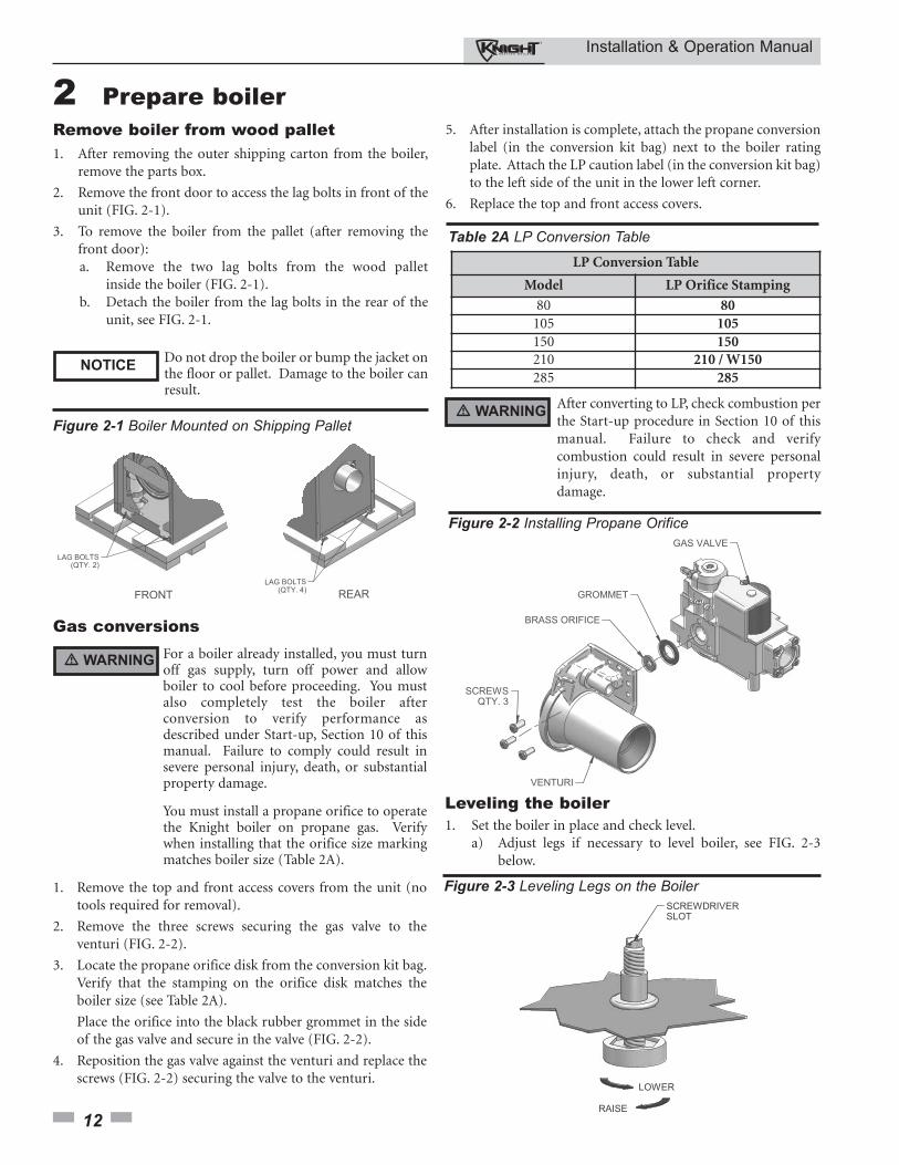
Figure 2-2 Installing Propane Orifice
Remove boiler from wood pallet1. After removing the outer shipping carton from the boiler,
remove the parts box.
2. Remove the front door to access the lag bolts in front of theunit (FIG. 2-1).
3. To remove the boiler from the pallet (after removing thefront door):a. Remove the two lag bolts from the wood pallet
inside the boiler (FIG. 2-1).b. Detach the boiler from the lag bolts in the rear of the
unit, see FIG. 2-1.
Do not drop the boiler or bump the jacket onthe floor or pallet. Damage to the boiler canresult.
For a boiler already installed, you must turnoff gas supply, turn off power and allowboiler to cool before proceeding. You mustalso completely test the boiler afterconversion to verify performance asdescribed under Start-up, Section 10 of thismanual. Failure to comply could result insevere personal injury, death, or substantialproperty damage.
You must install a propane orifice to operatethe Knight boiler on propane gas. Verifywhen installing that the orifice size markingmatches boiler size (Table 2A).
5. After installation is complete, attach the propane conversionlabel (in the conversion kit bag) next to the boiler ratingplate. Attach the LP caution label (in the conversion kit bag)to the left side of the unit in the lower left corner.
6. Replace the top and front access covers.
Figure 2-1 Boiler Mounted on Shipping Pallet
Gas conversions
NOTICE
� WARNING
Figure 2-3 Leveling Legs on the Boiler
Leveling the boiler1. Set the boiler in place and check level.
a) Adjust legs if necessary to level boiler, see FIG. 2-3 below.
� WARNINGAfter converting to LP, check combustion perthe Start-up procedure in Section 10 of thismanual. Failure to check and verifycombustion could result in severe personalinjury, death, or substantial propertydamage.
LP Conversion Table
Model LP Orifice Stamping
80 80105 105150 150210 210 / W150285 285
Table 2A LP Conversion Table
1. Remove the top and front access covers from the unit (notools required for removal).
2. Remove the three screws securing the gas valve to theventuri (FIG. 2-2).
3. Locate the propane orifice disk from the conversion kit bag.Verify that the stamping on the orifice disk matches theboiler size (see Table 2A).
Place the orifice into the black rubber grommet in the sideof the gas valve and secure in the valve (FIG. 2-2).
4. Reposition the gas valve against the venturi and replace thescrews (FIG. 2-2) securing the valve to the venturi.
Installation & Operation Manual
13
3 General venting
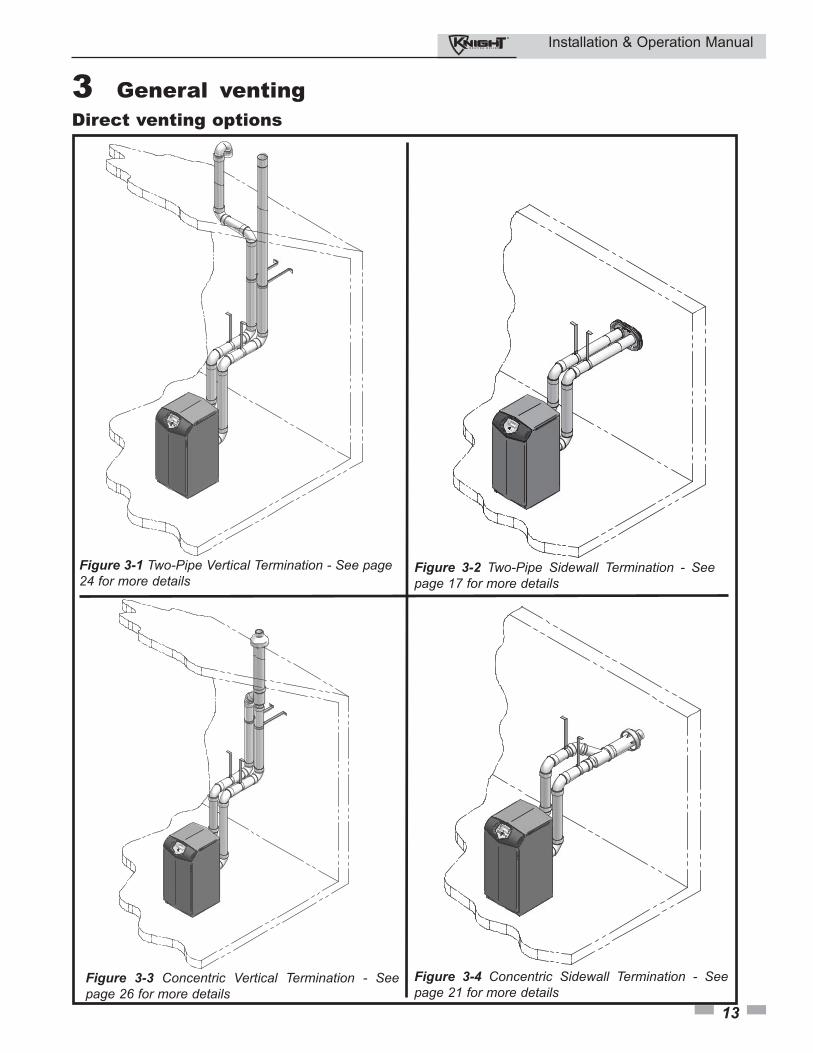
Figure 3-1 Two-Pipe Vertical Termination - See page24 for more details
Figure 3-2 Two-Pipe Sidewall Termination - Seepage 17 for more details
Figure 3-3 Concentric Vertical Termination - Seepage 26 for more details
Figure 3-4 Concentric Sidewall Termination - Seepage 21 for more details
Direct venting options
Installation & Operation Manual
14
3 General venting
Vent piping materials
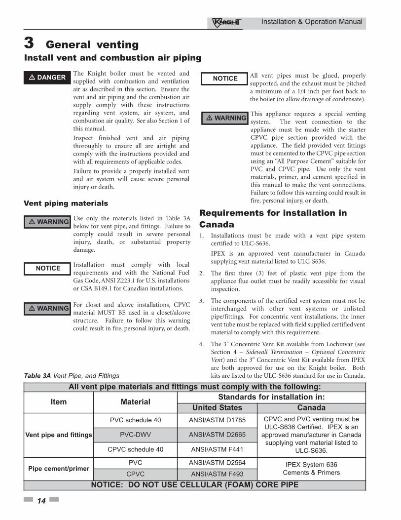
Use only the materials listed in Table 3Abelow for vent pipe, and fittings. Failure tocomply could result in severe personalinjury, death, or substantial propertydamage.
Installation must comply with localrequirements and with the National FuelGas Code, ANSI Z223.1 for U.S. installationsor CSA B149.1 for Canadian installations.
Table 3A Vent Pipe, and Fittings
Install vent and combustion air piping
� DANGERThe Knight boiler must be vented andsupplied with combustion and ventilationair as described in this section. Ensure thevent and air piping and the combustion airsupply comply with these instructionsregarding vent system, air system, andcombustion air quality. See also Section 1 ofthis manual.
Inspect finished vent and air pipingthoroughly to ensure all are airtight andcomply with the instructions provided andwith all requirements of applicable codes.
Failure to provide a properly installed ventand air system will cause severe personalinjury or death.
All vent pipes must be glued, properlysupported, and the exhaust must be pitcheda minimum of a 1/4 inch per foot back tothe boiler (to allow drainage of condensate).
This appliance requires a special ventingsystem. The vent connection to theappliance must be made with the starterCPVC pipe section provided with theappliance. The field provided vent fittingsmust be cemented to the CPVC pipe sectionusing an “All Purpose Cement” suitable forPVC and CPVC pipe. Use only the ventmaterials, primer, and cement specified inthis manual to make the vent connections.Failure to follow this warning could result infire, personal injury, or death.
� WARNING
NOTICE
� WARNING
� WARNINGFor closet and alcove installations, CPVCmaterial MUST BE used in a closet/alcovestructure. Failure to follow this warningcould result in fire, personal injury, or death.
NOTICE
All vent pipe materials and fittings must comply with the following:
Item MaterialStandards for installation in:
United States Canada
Vent pipe and fittings
PVC schedule 40 ANSI/ASTM D1785 CPVC and PVC venting must be
ULC-S636 Certified. IPEX is an
approved manufacturer in Canada
supplying vent material listed to
ULC-S636.
PVC-DWV ANSI/ASTM D2665
CPVC schedule 40 ANSI/ASTM F441
Pipe cement/primerPVC ANSI/ASTM D2564 IPEX System 636
Cements & PrimersCPVC ANSI/ASTM F493
NOTICE: DO NOT USE CELLULAR (FOAM) CORE PIPE
Requirements for installation inCanada1. Installations must be made with a vent pipe system
certified to ULC-S636.
IPEX is an approved vent manufacturer in Canada supplying vent material listed to ULC-S636.
2. The first three (3) feet of plastic vent pipe from the appliance flue outlet must be readily accessible for visual inspection.
3. The components of the certified vent system must not be interchanged with other vent systems or unlisted pipe/fittings. For concentric vent installations, the inner vent tube must be replaced with field supplied certifiedventmaterial to comply with this requirement.
4. The 3" Concentric Vent Kit available from Lochinvar (see Section 4 – Sidewall Termination – Optional Concentric Vent) and the 3" Concentric Vent Kit available from IPEX are both approved for use on the Knight boiler. Both kits are listed to the ULC-S636 standard for use in Canada.
Installation & Operation Manual
15
3 General venting (continued)
Air intake/vent connections
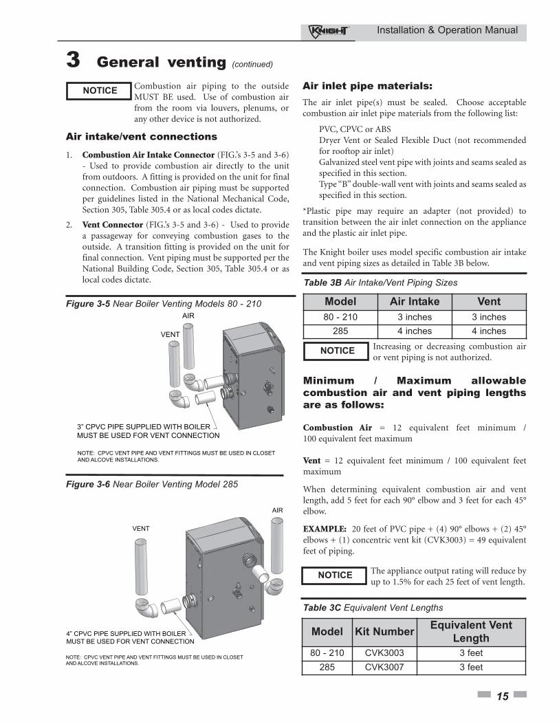
1. Combustion Air Intake Connector (FIG.’s 3-5 and 3-6) - Used to provide combustion air directly to the unit from outdoors. A fitting is provided on the unit for final connection. Combustion air piping must be supported per guidelines listed in the National Mechanical Code, Section 305, Table 305.4 or as local codes dictate.
2. Vent Connector (FIG.’s 3-5 and 3-6) - Used to provide a passageway for conveying combustion gases to the outside. A transition fitting is provided on the unit for final connection. Vent piping must be supported per the National Building Code, Section 305, Table 305.4 or as local codes dictate.
Combustion air piping to the outsideMUST BE used. Use of combustion airfrom the room via louvers, plenums, orany other device is not authorized.
NOTICE
3” CPVC PIPE SUPPLIED WITH BOILER
MUST BE USED FOR VENT CONNECTION
NOTE: CPVC VENT PIPE AND VENT FITTINGS MUST BE USED IN CLOSET
AND ALCOVE INSTALLATIONS.
Figure 3-5 Near Boiler Venting Models 80 - 210
4” CPVC PIPE SUPPLIED WITH BOILER
MUST BE USED FOR VENT CONNECTION
NOTE: CPVC VENT PIPE AND VENT FITTINGS MUST BE USED IN CLOSET
AND ALCOVE INSTALLATIONS.
Figure 3-6 Near Boiler Venting Model 285
The Knight boiler uses model specific combustion air intakeand vent piping sizes as detailed in Table 3B below.
Model Air Intake Vent
80 - 210 3 inches 3 inches
285 4 inches 4 inches
Table 3B Air Intake/Vent Piping Sizes
Increasing or decreasing combustion airor vent piping is not authorized.
NOTICE
Minimum / Maximum allowablecombustion air and vent piping lengthsare as follows:
Combustion Air = 12 equivalent feet minimum /100 equivalent feet maximum
Vent = 12 equivalent feet minimum / 100 equivalent feetmaximum
When determining equivalent combustion air and ventlength, add 5 feet for each 90° elbow and 3 feet for each 45°elbow.
EXAMPLE: 20 feet of PVC pipe + (4) 90° elbows + (2) 45°elbows + (1) concentric vent kit (CVK3003) = 49 equivalentfeet of piping.
Model Kit NumberEquivalent Vent
Length
80 - 210 CVK3003 3 feet
285 CVK3007 3 feet
Table 3C Equivalent Vent Lengths
The appliance output rating will reduce byup to 1.5% for each 25 feet of vent length.
NOTICE
Air inlet pipe materials:The air inlet pipe(s) must be sealed. Choose acceptablecombustion air inlet pipe materials from the following list:
PVC, CPVC or ABS Dryer Vent or Sealed Flexible Duct (not recommended for rooftop air inlet)Galvanized steel vent pipe with joints and seams sealed as specified in this section.Type “B” double-wall vent with joints and seams sealed as specified in this section.
*Plastic pipe may require an adapter (not provided) totransition between the air inlet connection on the applianceand the plastic air inlet pipe.
Installation & Operation Manual
16
3 General venting Vent, air piping and termination:
The Knight boiler vent and air piping can be installed throughthe roof or through a sidewall. Follow the procedures in thismanual for the method chosen. Refer to the information inthis manual to determine acceptable vent and air pipinglength.
Air contamination
Pool and laundry products and common household andhobby products often contain fluorine or chlorinecompounds. When these chemicals pass through the boiler,they can form strong acids. The acid can eat through theboiler wall, causing serious damage and presenting a possiblethreat of flue gas spillage or boiler water leakage into thebuilding.
Please read the information given in Table 1A, page 11, listingcontaminants and areas likely to contain them. Ifcontaminating chemicals will be present near the location ofthe boiler combustion air inlet, have your installer pipe theboiler combustion air and vent to another location, per thismanual.
If the boiler combustion air inlet islocated in a laundry room or pool facility,for example, these areas will alwayscontain hazardous contaminants.
To prevent the potential of severe personalinjury or death, check for areas andproducts listed in Table 1A, page 11 beforeinstalling the boiler or air inlet piping.
If contaminants are found, you MUST:• Remove contaminants permanently.
—OR—• Relocate air inlet and vent
terminations to other areas.
Removing from existing vent
Follow the instructions in Section 1, page 11 of this manualwhen removing a boiler from an existing vent system.
Vent and air piping
Vent and air system:
Installation must comply with localrequirements and with the National FuelGas Code, ANSI Z223.1 for U.S.installations or CSA B149.1 forCanadian installations.
You must also install air piping from outside to the boilerair intake adapter. The resultant installation is direct vent(sealed combustion).
You may use any of the vent/air piping methods covered inthis manual. Do not attempt to install the Knight boilerusing any other means.
DO NOT mix components fromdifferent systems. The vent system couldfail, causing leakage of flue products intothe living space. Use only PVC or CPVCpipe and fittings, with primer andcement specifically designed for thematerial used.
NOTICE
� WARNING
� WARNING
� WARNING
Installation & Operation Manual
17
4 Sidewall direct ventingVent/air termination – sidewall
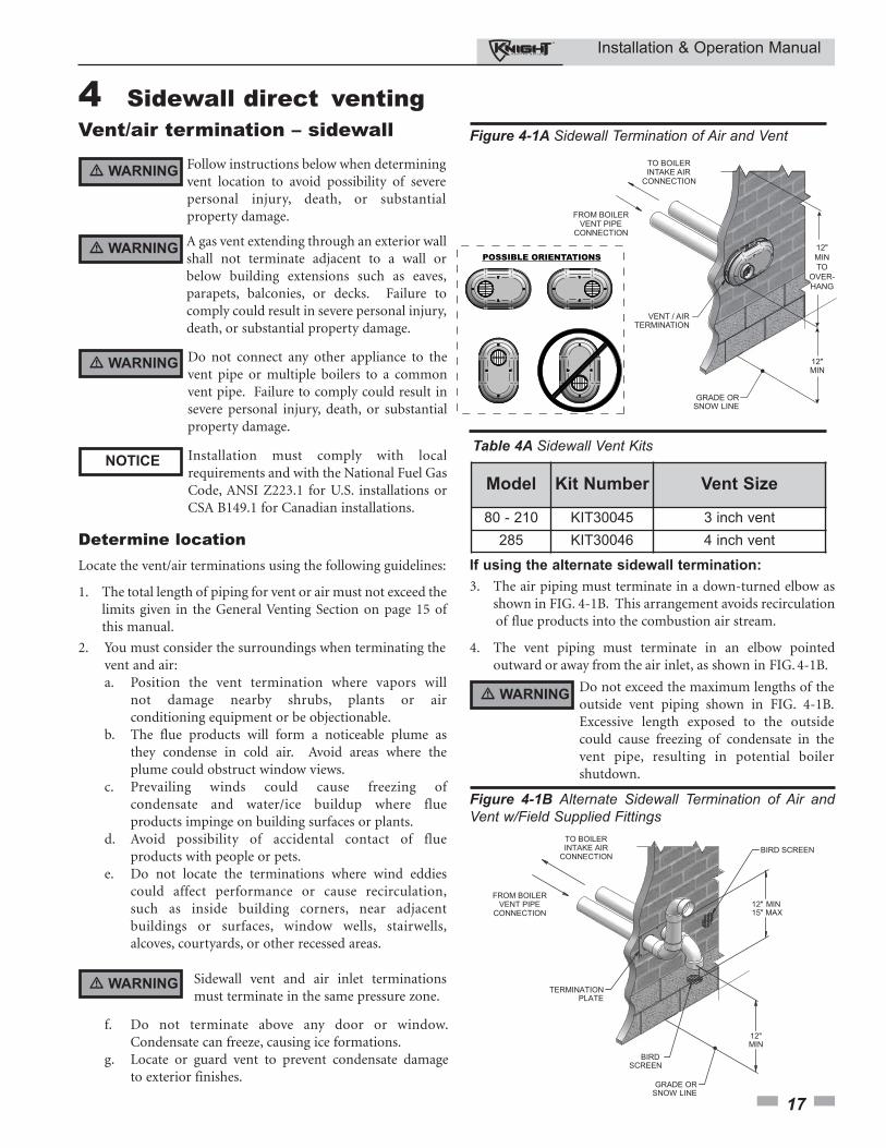
Follow instructions below when determiningvent location to avoid possibility of severepersonal injury, death, or substantialproperty damage.
A gas vent extending through an exterior wallshall not terminate adjacent to a wall orbelow building extensions such as eaves,parapets, balconies, or decks. Failure tocomply could result in severe personal injury,death, or substantial property damage.
Installation must comply with localrequirements and with the National Fuel GasCode, ANSI Z223.1 for U.S. installations orCSA B149.1 for Canadian installations.
Determine locationLocate the vent/air terminations using the following guidelines:
1. The total length of piping for vent or air must not exceed thelimits given in the General Venting Section on page 15 ofthis manual.
2. You must consider the surroundings when terminating thevent and air:a. Position the vent termination where vapors will
not damage nearby shrubs, plants or air conditioning equipment or be objectionable.
b. The flue products will form a noticeable plume as they condense in cold air. Avoid areas where the plume could obstruct window views.
c. Prevailing winds could cause freezing of condensate and water/ice buildup where flue products impinge on building surfaces or plants.
d. Avoid possibility of accidental contact of flue products with people or pets.
e. Do not locate the terminations where wind eddies could affect performance or cause recirculation, such as inside building corners, near adjacent buildings or surfaces, window wells, stairwells, alcoves, courtyards, or other recessed areas.
Do not exceed the maximum lengths of theoutside vent piping shown in FIG. 4-1B.Excessive length exposed to the outsidecould cause freezing of condensate in thevent pipe, resulting in potential boilershutdown.
Figure 4-1B Alternate Sidewall Termination of Air andVent w/Field Supplied Fittings
� WARNING
� WARNING
NOTICE
� WARNING
� WARNING Do not connect any other appliance to thevent pipe or multiple boilers to a commonvent pipe. Failure to comply could result insevere personal injury, death, or substantialproperty damage.
� WARNING Sidewall vent and air inlet terminationsmust terminate in the same pressure zone.
If using the alternate sidewall termination:
3. The air piping must terminate in a down-turned elbow asshown in FIG. 4-1B. This arrangement avoids recirculationof flue products into the combustion air stream.
4. The vent piping must terminate in an elbow pointedoutward or away from the air inlet, as shown in FIG. 4-1B.
f. Do not terminate above any door or window. Condensate can freeze, causing ice formations.
g. Locate or guard vent to prevent condensate damage to exterior finishes.
TO BOILERINTAKE AIR
CONNECTION
FROM BOILERVENT PIPE
CONNECTION
VENT / AIRTERMINATION
GRADE ORSNOW LINE
12"MIN
12"MINTO
OVER-HANG
POSSIBLE ORIENTATIONS
Figure 4-1A Sidewall Termination of Air and Vent
Model Kit Number Vent Size
80 - 210 KIT30045 3 inch vent
285 KIT30046 4 inch vent
Table 4A Sidewall Vent Kits
Installation & Operation Manual
18
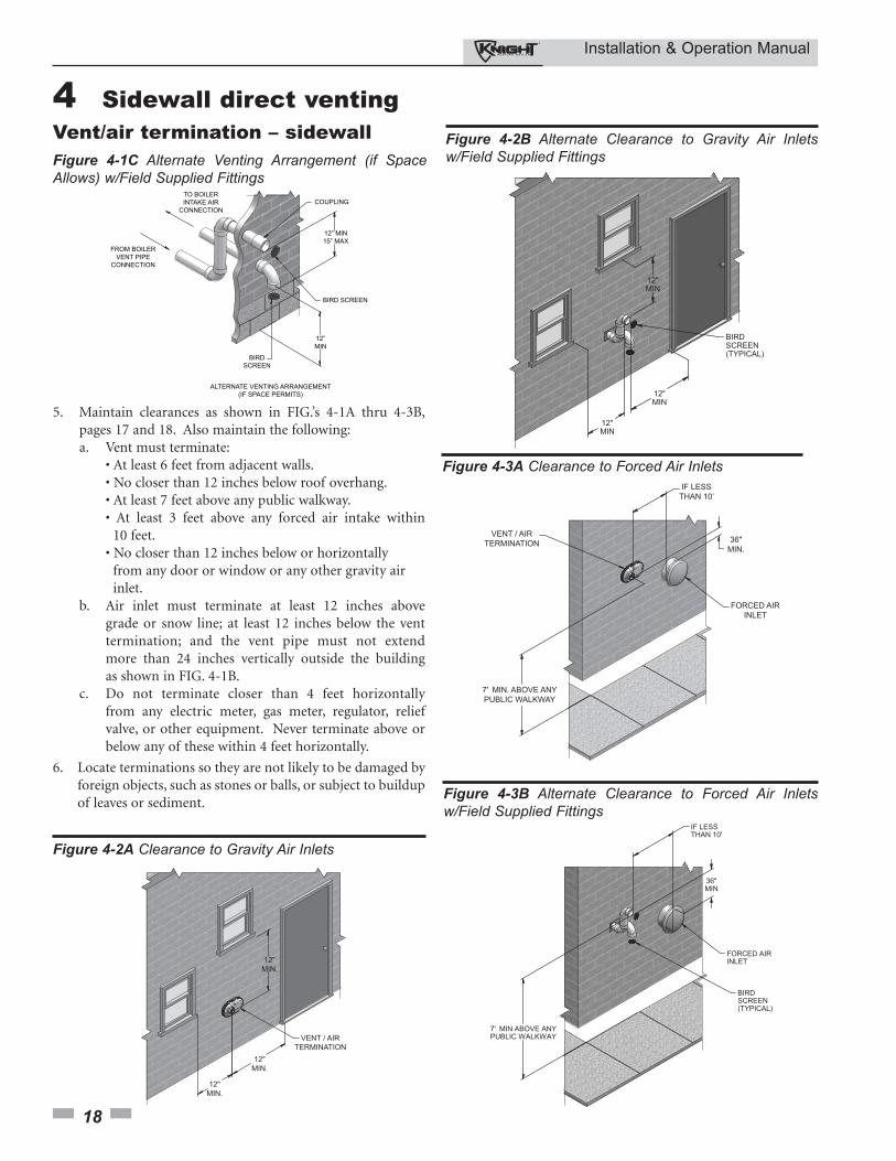
5. Maintain clearances as shown in FIG.’s 4-1A thru 4-3B, pages 17 and 18. Also maintain the following:a. Vent must terminate:
• At least 6 feet from adjacent walls.• No closer than 12 inches below roof overhang.• At least 7 feet above any public walkway.• At least 3 feet above any forced air intake within
10 feet.• No closer than 12 inches below or horizontally
from any door or window or any other gravity air inlet.
b. Air inlet must terminate at least 12 inches above grade or snow line; at least 12 inches below the vent termination; and the vent pipe must not extend more than 24 inches vertically outside the building as shown in FIG. 4-1B.
c. Do not terminate closer than 4 feet horizontally from any electric meter, gas meter, regulator, relief valve, or other equipment. Never terminate above or below any of these within 4 feet horizontally.
6. Locate terminations so they are not likely to be damaged byforeign objects, such as stones or balls, or subject to buildupof leaves or sediment.
Vent/air termination – sidewall 4 Sidewall direct venting
ALTERNATE VENTING ARRANGEMENT
(IF SPACE PERMITS)
BIRD
SCREEN
12”
MIN
12” MIN
15” MAX
COUPLINGTO BOILER
INTAKE AIR
CONNECTION
FROM BOILER
VENT PIPE
CONNECTION
BIRD SCREEN
Figure 4-1C Alternate Venting Arrangement (if SpaceAllows) w/Field Supplied Fittings
VENT / AIRTERMINATION
12"MIN.
12"MIN.
12"MIN.
Figure 4-2A Clearance to Gravity Air Inlets
Figure 4-2B Alternate Clearance to Gravity Air Inletsw/Field Supplied Fittings
FORCED AIRINLET
VENT / AIRTERMINATION
7' MIN. ABOVE ANYPUBLIC WALKWAY
IF LESSTHAN 10’
36"MIN.
Figure 4-3A Clearance to Forced Air Inlets
Figure 4-3B Alternate Clearance to Forced Air Inletsw/Field Supplied Fittings
Installation & Operation Manual
19
4 Sidewall direct venting
Termination and fittings1. The air termination coupling must be oriented at least
12 inches above grade or snow line as shown in FIG. 4-1A,page 17.
2. Maintain the required dimensions of the finishedtermination piping as shown in FIG. 4-1A, page 17.
3. If using the alternate sidewall termination do not extendexposed vent pipe outside of the building more than what isshown in this document. Condensate could freeze andblock vent pipe.
4. PVC/CPVC terminations are designed to accommodate anywall thickness of standard constructions per the directionsfound in this manual.
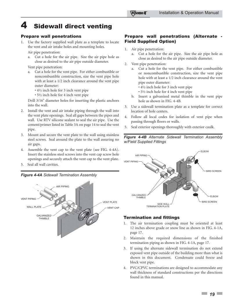
Prepare wall penetrations (Alternate -Field Supplied Option)
1. Air pipe penetration:a. Cut a hole for the air pipe. Size the air pipe hole as
close as desired to the air pipe outside diameter.
2. Vent pipe penetration:a. Cut a hole for the vent pipe. For either combustible
or noncombustible construction, size the vent pipe hole with at least a 1/2 inch clearance around the vent pipe outer diameter:• 4½ inch hole for 3 inch vent pipe• 5½ inch hole for 4 inch vent pipe
b. Insert a galvanized metal thimble in the vent pipe hole as shown in FIG. 4-4B.
3. Use a sidewall termination plate as a template for correctlocation of hole centers.
4. Follow all local codes for isolation of vent pipe whenpassing through floors or walls.
5. Seal exterior openings thoroughly with exterior caulk.
VENT PIPING
GALVANIZEDTHIMBLE
VENT CAP
AIR PIPING
WALL PLATE
VENT PLATE
Figure 4-4A Sidewall Termination Assembly
Figure 4-4B Alternate Sidewall Termination Assemblyw/Field Supplied Fittings
Prepare wall penetrations1. Use the factory supplied wall plate as a template to locate
the vent and air intake holes and mounting holes.
Air pipe penetration:a. Cut a hole for the air pipe. Size the air pipe hole as
close as desired to the air pipe outside diameter.
Vent pipe penetration:a. Cut a hole for the vent pipe. For either combustible or
noncombustible construction, size the vent pipe hole with at least a 1/2 inch clearance around the vent pipe outer diameter:• 4½ inch hole for 3 inch vent pipe• 5½ inch hole for 4 inch vent pipe
Drill 3/16" diameter holes for inserting the plastic anchors into the wall.
2. Install the vent and air intake piping through the wall into the vent plate openings. Seal all gaps between the pipes and wall. Use RTV silicone sealant to seal the air pipe. Use the cement/primer listed in Table 3A on page 14 to seal the vent pipe.
3. Mount and secure the vent plate to the wall using stainless steel screws. Seal around the plate to the wall assuring no air gaps.
4. Assemble the vent cap to the vent plate (see FIG. 4-4A). Insert the stainless steel screws into the vent cap screw hole openings and securely attach the vent cap to the vent plate.
5. Seal all wall cavities.
Installation & Operation Manual
20
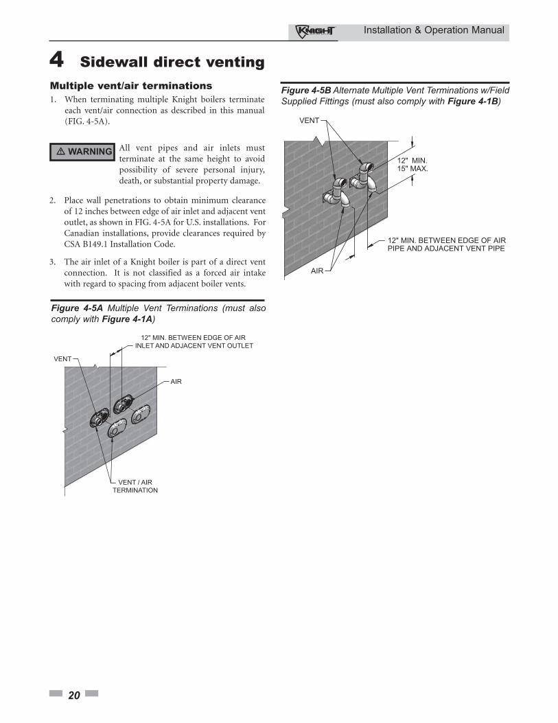
12" MIN. BETWEEN EDGE OF AIR INLET AND ADJACENT VENT OUTLET
VENT / AIRTERMINATION
VENT
AIR
Figure 4-5A Multiple Vent Terminations (must alsocomply with Figure 4-1A)
All vent pipes and air inlets mustterminate at the same height to avoidpossibility of severe personal injury,death, or substantial property damage.
Multiple vent/air terminations1. When terminating multiple Knight boilers terminate
each vent/air connection as described in this manual(FIG. 4-5A).
2. Place wall penetrations to obtain minimum clearanceof 12 inches between edge of air inlet and adjacent ventoutlet, as shown in FIG. 4-5A for U.S. installations. ForCanadian installations, provide clearances required byCSA B149.1 Installation Code.
3. The air inlet of a Knight boiler is part of a direct ventconnection. It is not classified as a forced air intakewith regard to spacing from adjacent boiler vents.
� WARNING
Figure 4-5B Alternate Multiple Vent Terminations w/FieldSupplied Fittings (must also comply with Figure 4-1B)
4 Sidewall direct venting
Installation & Operation Manual
21
4 Sidewall direct venting (continued)
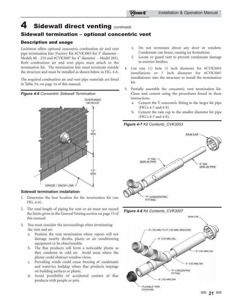
4" DIA.SDR-26 PIPE
3" DIA.SDR-26 PIPE
RAIN CAP
"Y" CONCENTRICFITTING
Figure 4-7 Kit Contents_CVK3003
Sidewall termination installation
1. Determine the best location for the termination kit (seeFIG. 4-6).
2. The total length of piping for vent or air must not exceedthe limits given in the General Venting section on page 15 ofthis manual.
3. You must consider the surroundings when terminating the vent and air:a. Position the vent termination where vapors will not
damage nearby shrubs, plants or air conditioning equipment or be objectionable.
b. The flue products will form a noticeable plume as they condense in cold air. Avoid areas where the plume could obstruct window views.
c. Prevailing winds could cause freezing of condensate and water/ice buildup where flue products impinge on building surfaces or plants.
d. Avoid possibility of accidental contact of flue products with people or pets.
4" (102 MM) DIA.
6" (152 MM) DIA.
RAIN CAP
"Y" CONCENTRICFITTING
"FLEXIBLE" PIPECOUPLING
6" (152 MM) DIA.
6" (152 MM) DIA.
6" (152 MM) TO 4" (102 MM) REDUCER
Figure 4-8 Kit Contents_CVK3007
e. Do not terminate above any door or window. Condensate can freeze, causing ice formations.
f. Locate or guard vent to prevent condensate damage to exterior finishes.
4. Cut one (1) hole (5 inch diameter for #CVK3003installations or 7 inch diameter for #CVK3007installations) into the structure to install the terminationkit.
5. Partially assemble the concentric vent termination kit.Clean and cement using the procedures found in theseinstructions.a. Cement the Y concentric fitting to the larger kit pipe
(FIG.’s 4-7 and 4-8).b. Cement the rain cap to the smaller diameter kit pipe
(FIG.’s 4-7 and 4-8).
Sidewall termination – optional concentric vent Description and usageLochinvar offers optional concentric combustion air and ventpipe termination kits (Factory Kit #CVK3003 for 3" diameter -Models 80 - 210 and #CVK3007 for 4" diameter - Model 285).Both combustion air and vent pipes must attach to thetermination kit. The termination kits must terminate outsidethe structure and must be installed as shown below in FIG. 4-6.
The required combustion air and vent pipe materials are listedin Table 3A, on page 14 of this manual.
Figure 4-6 Concentric Sidewall Termination
Installation & Operation Manual
22
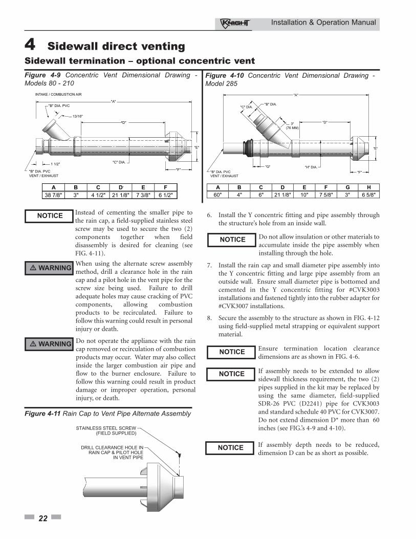
4 Sidewall direct venting Sidewall termination – optional concentric vent Figure 4-9 Concentric Vent Dimensional Drawing -Models 80 - 210
Instead of cementing the smaller pipe tothe rain cap, a field-supplied stainless steelscrew may be used to secure the two (2)components together when fielddisassembly is desired for cleaning (seeFIG. 4-11).
When using the alternate screw assemblymethod, drill a clearance hole in the raincap and a pilot hole in the vent pipe for thescrew size being used. Failure to drilladequate holes may cause cracking of PVCcomponents, allowing combustionproducts to be recirculated. Failure tofollow this warning could result in personalinjury or death.
Do not operate the appliance with the raincap removed or recirculation of combustionproducts may occur. Water may also collectinside the larger combustion air pipe andflow to the burner enclosure. Failure tofollow this warning could result in productdamage or improper operation, personalinjury, or death.
Figure 4-11 Rain Cap to Vent Pipe Alternate Assembly
6. Install the Y concentric fitting and pipe assembly throughthe structure’s hole from an inside wall.
Do not allow insulation or other materials toaccumulate inside the pipe assembly wheninstalling through the hole.
7. Install the rain cap and small diameter pipe assembly intothe Y concentric fitting and large pipe assembly from anoutside wall. Ensure small diameter pipe is bottomed andcemented in the Y concentric fitting for #CVK3003installations and fastened tightly into the rubber adapter for#CVK3007 installations.
8. Secure the assembly to the structure as shown in FIG. 4-12using field-supplied metal strapping or equivalent supportmaterial.
Ensure termination location clearancedimensions are as shown in FIG. 4-6.
If assembly needs to be extended to allowsidewall thickness requirement, the two (2)pipes supplied in the kit may be replaced byusing the same diameter, field-suppliedSDR-26 PVC (D2241) pipe for CVK3003and standard schedule 40 PVC for CVK3007.Do not extend dimension D* more than 60inches (see FIG.’s 4-9 and 4-10).
NOTICE
� WARNING
� WARNING
NOTICE
NOTICE
NOTICE
If assembly depth needs to be reduced,dimension D can be as short as possible.
NOTICE
"B" DIA. PVCVENT / EXHAUST
"A"
"H" DIA.
"D"
"E"
"F""G"
3"(76 MM)
"C" DIA."B" DIA.
Figure 4-10 Concentric Vent Dimensional Drawing -Model 285
Installation & Operation Manual
23
4 Sidewall direct venting (continued)
Sidewall termination – optional concentric vent
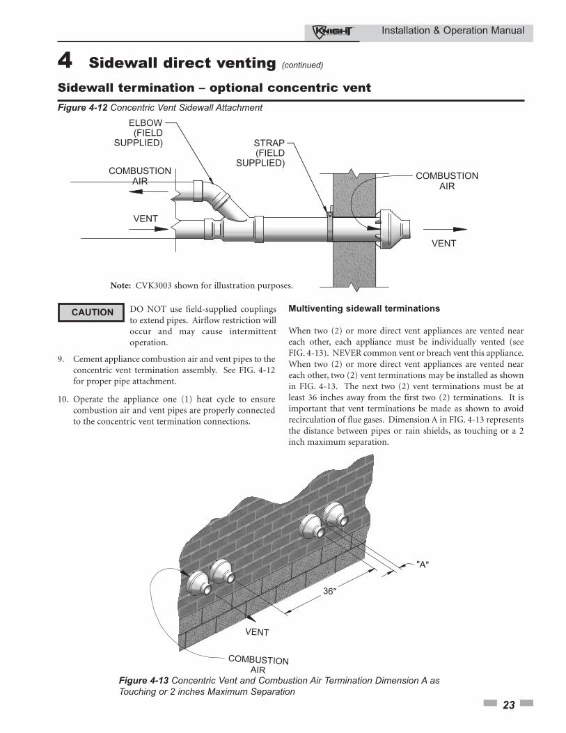
Multiventing sidewall terminations
When two (2) or more direct vent appliances are vented neareach other, each appliance must be individually vented (seeFIG. 4-13). NEVER common vent or breach vent this appliance.When two (2) or more direct vent appliances are vented neareach other, two (2) vent terminations may be installed as shownin FIG. 4-13. The next two (2) vent terminations must be atleast 36 inches away from the first two (2) terminations. It isimportant that vent terminations be made as shown to avoidrecirculation of flue gases. Dimension A in FIG. 4-13 representsthe distance between pipes or rain shields, as touching or a 2inch maximum separation.
Figure 4-13 Concentric Vent and Combustion Air Termination Dimension A asTouching or 2 inches Maximum Separation
Figure 4-12 Concentric Vent Sidewall Attachment
DO NOT use field-supplied couplingsto extend pipes. Airflow restriction willoccur and may cause intermittentoperation.
9. Cement appliance combustion air and vent pipes to theconcentric vent termination assembly. See FIG. 4-12for proper pipe attachment.
10. Operate the appliance one (1) heat cycle to ensurecombustion air and vent pipes are properly connectedto the concentric vent termination connections.
CAUTION
Note: CVK3003 shown for illustration purposes.
Installation & Operation Manual
24
5 Vertical direct ventingVent/air termination – vertical
Follow instructions below whendetermining vent location to avoidpossibility of severe personal injury, deathor substantial property damage.
Installation must comply with localrequirements and with the National FuelGas Code, ANSI Z223.1 for U.S.installations or CSA B149.1 for Canadianinstallations.
Determine locationLocate the vent/air terminations using the followingguidelines:
1. The total length of piping for vent or air must not exceedthe limits given in the General Venting Section on page15 of this manual.
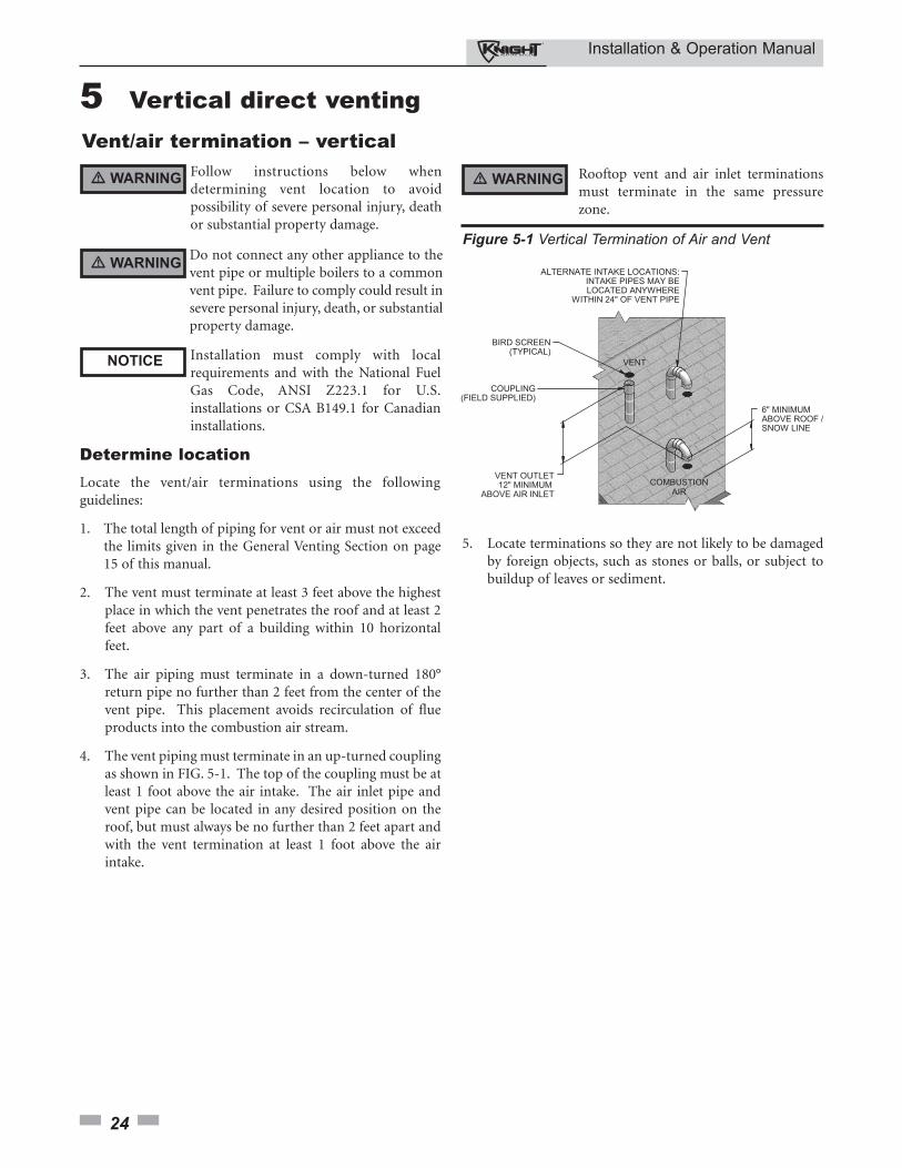
2. The vent must terminate at least 3 feet above the highestplace in which the vent penetrates the roof and at least 2feet above any part of a building within 10 horizontalfeet.
3. The air piping must terminate in a down-turned 180°return pipe no further than 2 feet from the center of thevent pipe. This placement avoids recirculation of flueproducts into the combustion air stream.
4. The vent piping must terminate in an up-turned couplingas shown in FIG. 5-1. The top of the coupling must be atleast 1 foot above the air intake. The air inlet pipe andvent pipe can be located in any desired position on theroof, but must always be no further than 2 feet apart andwith the vent termination at least 1 foot above the airintake.
Figure 5-1 Vertical Termination of Air and Vent
5. Locate terminations so they are not likely to be damagedby foreign objects, such as stones or balls, or subject tobuildup of leaves or sediment.
� WARNING
NOTICE
� WARNINGDo not connect any other appliance to thevent pipe or multiple boilers to a commonvent pipe. Failure to comply could result insevere personal injury, death, or substantialproperty damage.
� WARNING Rooftop vent and air inlet terminationsmust terminate in the same pressurezone.
Installation & Operation Manual
25
5 Vertical direct venting (continued)
Vent/air termination – vertical
Prepare roof penetrations
1. Air pipe penetration:a. Cut a hole for the air pipe. Size the air pipe hole as
close as desired to the air pipe outside diameter.
2. Vent pipe penetration:a. Cut a hole for the vent pipe. For either combustible
or noncombustible construction, size the vent pipe hole with at least a 1/2 inch clearance around the vent pipe outer diameter:• 4½ inch hole for 3 inch vent pipe• 5½ inch hole for 4 inch vent pipe
b. Insert a galvanized metal thimble in the vent pipe hole.
3. Space the air and vent holes to provide the minimumspacing shown in FIG. 5-1, page 24.
4. Follow all local codes for isolation of vent pipe whenpassing through floors, ceilings, and roofs.
5. Provide flashing and sealing boots sized for the vent pipeand air pipe.
Termination and fittings
1. Prepare the vent termination coupling and the airtermination elbow (FIG. 5-1) by inserting the bird screensprovided with the boiler. Bird screens are provided foreither 3" (Knight 80 – 105 – 150 and 210) or 4" (Knight285) fittings.
2. The air piping must terminate in a down-turned 180°return bend as shown in FIG. 5-1. Locate the air inlet pipeno further than 2 feet from the center of the vent pipe.This placement avoids recirculation of flue products intothe combustion air stream.
3. The vent piping must terminate in an up-turned couplingas shown in FIG. 5-1. The top of the coupling must be atleast 1 foot above the air intake. The air inlet pipe andvent pipe can be located in any desired position on theroof, but must always be no further than 2 feet apart andwith the vent termination at least 1 foot above the airintake.
4. Maintain the required dimensions of the finishedtermination piping as shown in FIG. 5-1.
5. Do not extend exposed vent pipe outside of buildingmore than shown in this document. Condensate couldfreeze and block vent pipe.
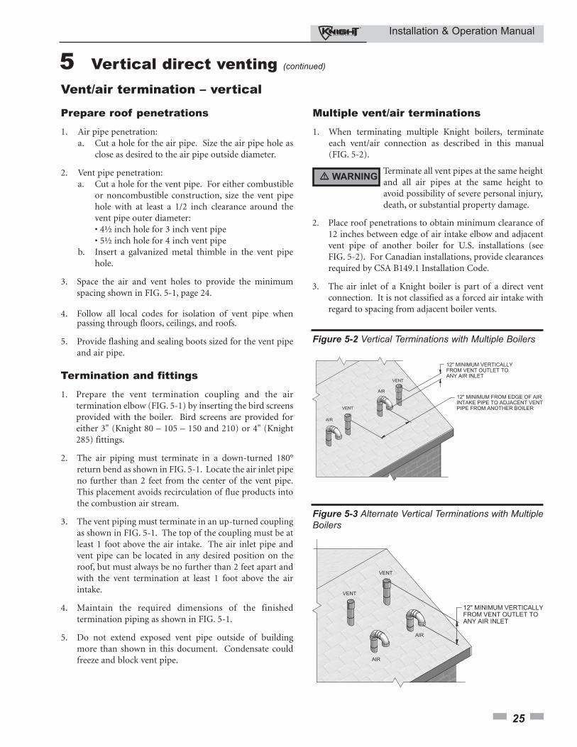
Multiple vent/air terminations
1. When terminating multiple Knight boilers, terminateeach vent/air connection as described in this manual(FIG. 5-2).
Terminate all vent pipes at the same heightand all air pipes at the same height toavoid possibility of severe personal injury,death, or substantial property damage.
2. Place roof penetrations to obtain minimum clearance of12 inches between edge of air intake elbow and adjacentvent pipe of another boiler for U.S. installations (seeFIG. 5-2). For Canadian installations, provide clearancesrequired by CSA B149.1 Installation Code.
3. The air inlet of a Knight boiler is part of a direct ventconnection. It is not classified as a forced air intake withregard to spacing from adjacent boiler vents.
Figure 5-2 Vertical Terminations with Multiple Boilers
Figure 5-3 Alternate Vertical Terminations with MultipleBoilers
� WARNING
Installation & Operation Manual
26
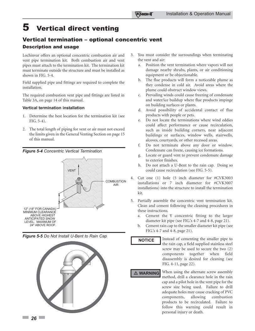
5 Vertical direct venting Vertical termination – optional concentric vent Description and usage
Lochinvar offers an optional concentric combustion air andvent pipe termination kit. Both combustion air and ventpipes must attach to the termination kit. The termination kitmust terminate outside the structure and must be installed asshown in FIG. 5-4.
Field supplied pipe and fittings are required to complete theinstallation.
The required combustion vent pipe and fittings are listed inTable 3A, on page 14 of this manual.
Vertical termination installation
1. Determine the best location for the termination kit (seeFIG. 5-4).
2. The total length of piping for vent or air must not exceedthe limits given in the General Venting Section on page 15of this manual.
Instead of cementing the smaller pipe tothe rain cap, a field supplied stainless steelscrew may be used to secure the two (2)components together when fielddisassembly is desired for cleaning (seeFIG. 4-11, page 22).
When using the alternate screw assemblymethod, drill a clearance hole in the raincap and a pilot hole in the vent pipe for thescrew size being used. Failure to drilladequate holes may cause cracking of PVCcomponents, allowing combustionproducts to be recirculated. Failure tofollow this warning could result inpersonal injury or death.
3. You must consider the surroundings when terminatingthe vent and air:a. Position the vent termination where vapors will not
damage nearby shrubs, plants, or air conditioning equipment or be objectionable.
b. The flue products will form a noticeable plume as they condense in cold air. Avoid areas where the plume could obstruct window views.
c. Prevailing winds could cause freezing of condensate and water/ice buildup where flue products impinge on building surfaces or plants.
d. Avoid possibility of accidental contact of flue products with people or pets.
e. Do not locate the terminations where wind eddies could affect performance or cause recirculation, such as inside building corners, near adjacent buildings or surfaces, window wells, stairwells, alcoves, courtyards, or other recessed areas.
f. Do not terminate above any door or window. Condensate can freeze, causing ice formations.
g. Locate or guard vent to prevent condensate damage to exterior finishes.
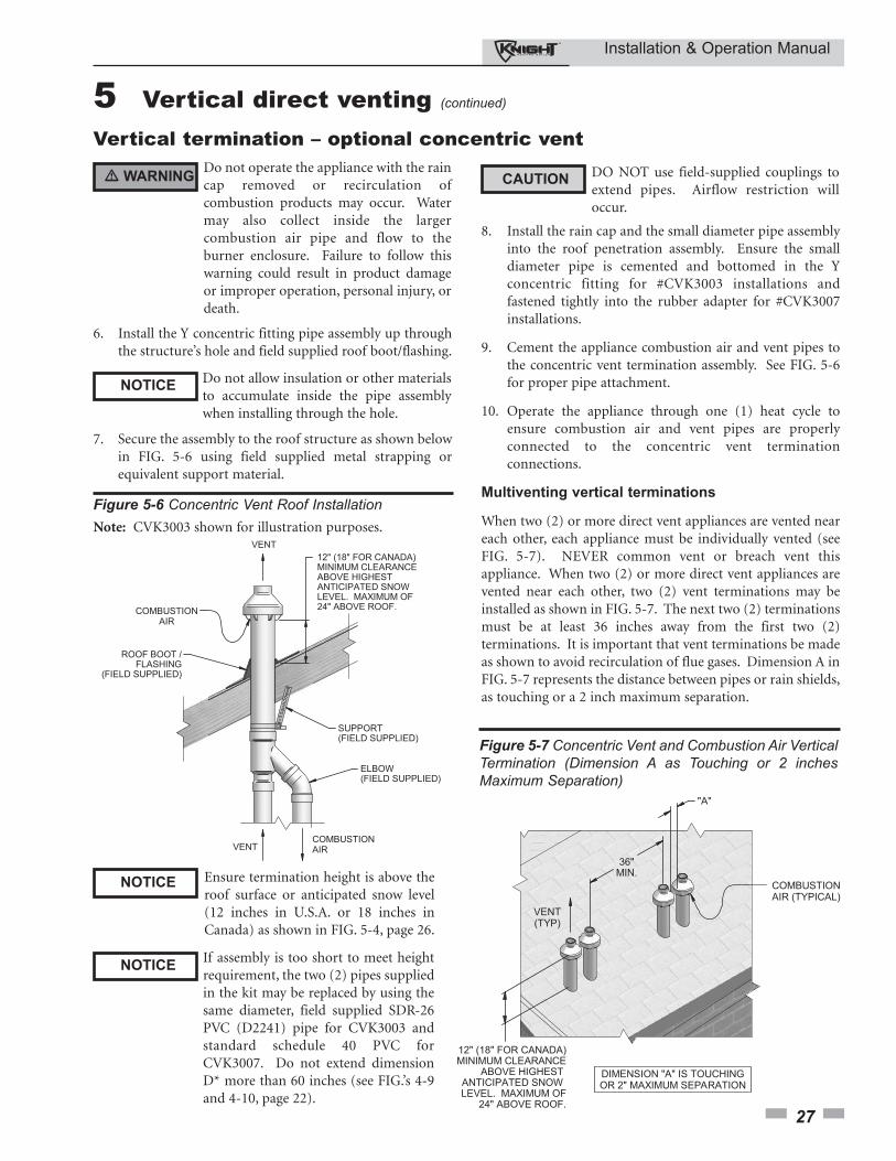
h. Do not attach a U-Bent to the rain cap. Doing so could cause recirculation (see FIG. 5-5).
4. Cut one (1) hole (5 inch diameter for #CVK3003installations or 7 inch diameter for #CVK3007installations) into the structure to install the terminationkit.
5. Partially assemble the concentric vent termination kit.Clean and cement following the cleaning procedures inthese instructions.a. Cement the Y concentric fitting to the larger
diameter kit pipe (see FIG.’s 4-7 and 4-8, page 21).b. Cement rain cap to the smaller diameter kit pipe (see
FIG.’s 4-7 and 4-8, page 21).
Figure 5-4 Concentric Vertical Termination
NOTICE
� WARNING
Figure 5-5 Do Not Install U-Bent to Rain Cap
Installation & Operation Manual
27
5 Vertical direct venting (continued)
Vertical termination – optional concentric vent
Figure 5-6 Concentric Vent Roof Installation
Ensure termination height is above theroof surface or anticipated snow level(12 inches in U.S.A. or 18 inches inCanada) as shown in FIG. 5-4, page 26.
If assembly is too short to meet heightrequirement, the two (2) pipes suppliedin the kit may be replaced by using thesame diameter, field supplied SDR-26PVC (D2241) pipe for CVK3003 andstandard schedule 40 PVC forCVK3007. Do not extend dimensionD* more than 60 inches (see FIG.’s 4-9and 4-10, page 22).
CAUTIONDO NOT use field-supplied couplings toextend pipes. Airflow restriction willoccur.
8. Install the rain cap and the small diameter pipe assemblyinto the roof penetration assembly. Ensure the smalldiameter pipe is cemented and bottomed in the Yconcentric fitting for #CVK3003 installations andfastened tightly into the rubber adapter for #CVK3007installations.
9. Cement the appliance combustion air and vent pipes tothe concentric vent termination assembly. See FIG. 5-6for proper pipe attachment.
10. Operate the appliance through one (1) heat cycle toensure combustion air and vent pipes are properlyconnected to the concentric vent terminationconnections.
Multiventing vertical terminations
When two (2) or more direct vent appliances are vented neareach other, each appliance must be individually vented (seeFIG. 5-7). NEVER common vent or breach vent thisappliance. When two (2) or more direct vent appliances arevented near each other, two (2) vent terminations may beinstalled as shown in FIG. 5-7. The next two (2) terminationsmust be at least 36 inches away from the first two (2)terminations. It is important that vent terminations be madeas shown to avoid recirculation of flue gases. Dimension A inFIG. 5-7 represents the distance between pipes or rain shields,as touching or a 2 inch maximum separation.
Figure 5-7 Concentric Vent and Combustion Air VerticalTermination (Dimension A as Touching or 2 inchesMaximum Separation)
Do not operate the appliance with the raincap removed or recirculation ofcombustion products may occur. Watermay also collect inside the largercombustion air pipe and flow to theburner enclosure. Failure to follow thiswarning could result in product damageor improper operation, personal injury, ordeath.
6. Install the Y concentric fitting pipe assembly up throughthe structure’s hole and field supplied roof boot/flashing.
Do not allow insulation or other materialsto accumulate inside the pipe assemblywhen installing through the hole.
7. Secure the assembly to the roof structure as shown belowin FIG. 5-6 using field supplied metal strapping orequivalent support material.
� WARNING
NOTICE
NOTICE
NOTICE
Note: CVK3003 shown for illustration purposes.

Installation & Operation Manual
28
6 Hydronic pipingSystem water piping methodsThe Knight is designed to function in a closed looppressurized system not less than 12 psi. A temperature andpressure gauge is included to monitor system pressure andoutlet temperature and should be located on the boiler outlet.
It is important to note that the boiler has a minimal amountof pressure drop and must be figured in when sizing thecirculators. Each boiler installation must have an airelimination device, which will remove air from the system.Install the boiler so the gas ignition system components areprotected from water (dripping, spraying, etc.) duringappliance operation for basic service of circulatorreplacement, valves, and others.
Observe a minimum of 1 inch clearance around allun-insulated hot water pipes when openings around the pipesare not protected by non-combustible materials.
Low water cutoff deviceOn a boiler installed above radiation level, some states andlocal codes require a low water cutoff device at the time ofinstallation.
Chilled water systemIf the boiler supplies hot water to heating coils in air handlerunits, flow control valves or other devices must be installed toprevent gravity circulation of heater water in the coils duringthe cooling cycle. A chilled water medium must be piped inparallel with the heater.
Freeze protectionFreeze protection for new or existing systems must use glycolthat is specially formulated for this purpose. This includesinhibitors, which prevent the glycol from attacking themetallic system components. Make certain to check that thesystem fluid is correct for the glycol concentration andinhibitor level. The system should be tested at least once ayear and as recommended by the producer of the glycolsolution. Allowance should be made for the expansion of theglycol solution in the system piping.
3. Install purge and balance valve or shutoff valve and drainon system return to purge air out of each zone.
4. Install a backflow preventer on the cold feed make-up waterline.
5. Install a pressure reducing valve on the cold feed make-upwater line, (15 psi nominal). Check temperature andpressure gauge (shipped separately), which should read aminimum pressure of 12 psi.
6. Install a circulator as shown on the piping diagrams in thissection. Make sure the circulator is properly sized for thesystem and friction loss.
7. Install an expansion tank on the system supply. Consult thetank manufacturer’s instruction for specific informationrelating to tank installation. Size the expansion tank for therequired system volume and capacity.
8. Install an air elimination device on the system supply.
9. Install a drain valve at the lowest point of the system.Note: The boiler cannot be drained completely of waterwithout purging the unit with an air pressure of 15 psi.
10. This appliance is supplied with a relief valve sized inaccordance with ASME Boiler and Pressure Vessel Code,Section IV (“Heating Boilers”). Pipe the discharge of thesafety relief valve to prevent injury in the event of pressurerelief. Pipe the discharge to a drain. Provide piping that isthe same size as the safety relief valve outlet. Never blockthe outlet of the safety relief valve.
See the *piping illustrations included in this section, FIG.’s 6-4thru 6-9 for suggested guidelines in piping the Knight boilerwith either zone valves or circulator pumps.
*Please note that these illustrations aremeant to show system piping concept only,the installer is responsible for all equipmentand detailing required by local codes.
Use only inhibited propylene glycolsolutions, which are specificallyformulated for hydronic systems. Ethyleneglycol is toxic and can attack gaskets andseals used in hydronic systems.
� WARNING
NOTICE
General piping informationBasic steps are listed in this section along with illustrations onthe following pages (FIG.’s 6-4 thru 6-9), which will guide youthrough the installation of the Knight boiler (referenceFIG. 6-2).
1. Connect the system return marked “Inlet”, make sure toinstall with pipe sealant compound.
2. Connect the system supply marked “Outlet”, make sure toinstall with pipe sealant compound.
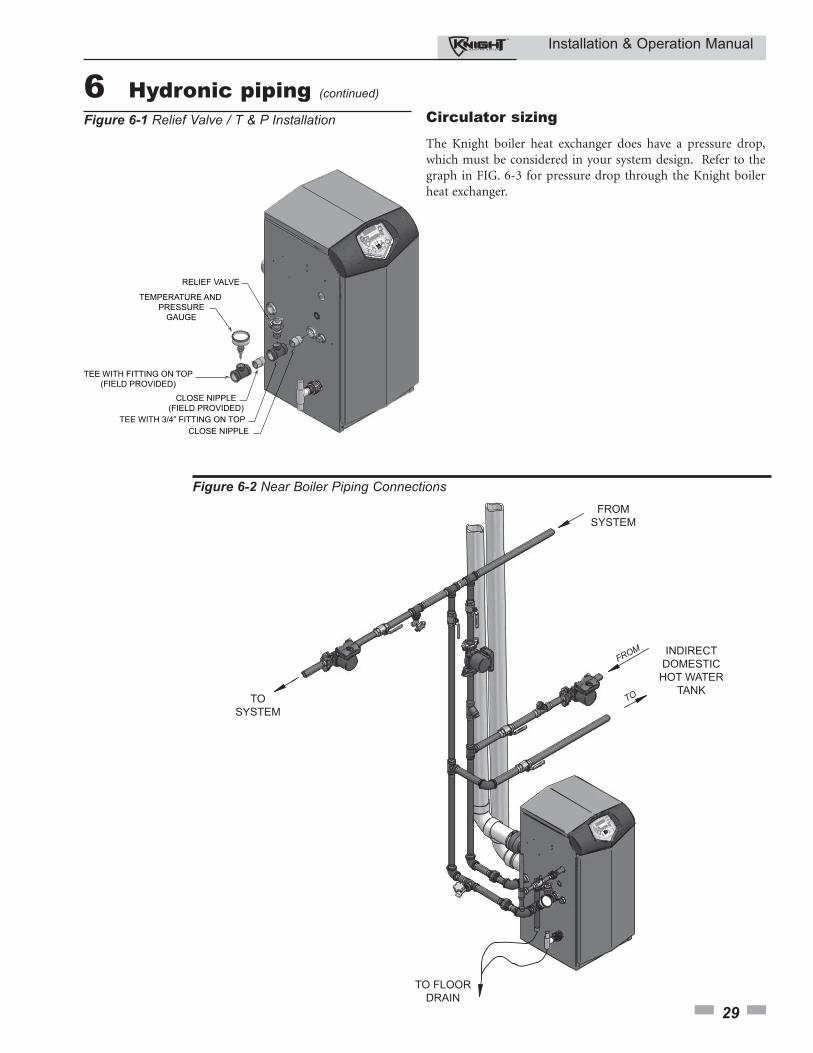
Relief valve and temperature and pressuregauge installationBasic steps are listed below to guide you through the installationof the relief valve and the temperature and pressure (T & P)gauge provided with the unit.
1. Install the tee with the 3/4 inch fitting positioned vertically and on the top as shown in FIG. 6-1.
2. Install the relief valve into the 3/4 inch fitting of the tee installed in Step 1 (FIG. 6-1).
3. Install a field provided close nipple and tee with the fitting positioned vertically on the top on the downstream side of the relief valve (see FIG. 6-1).
4. Install the temperature and pressure gauge provided with the unit into the top fitting of the tee (a bushing may be necessary) installed in Step 3 (FIG. 6-1).
� WARNINGThe relief valve, tee and any necessaryfittings are shipped in the install kit with theboiler and are to be field installed (FIG. 6-1).
Installation & Operation Manual
29
6 Hydronic piping (continued)
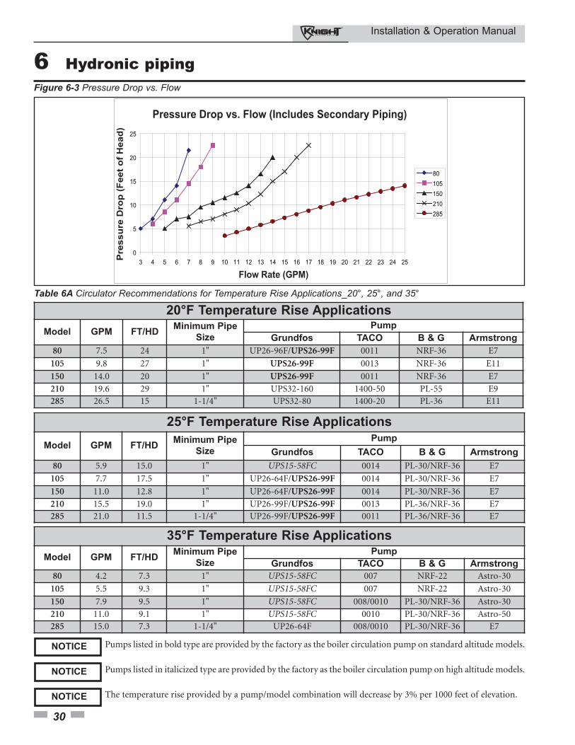
Circulator sizing
The Knight boiler heat exchanger does have a pressure drop,which must be considered in your system design. Refer to thegraph in FIG. 6-3 for pressure drop through the Knight boilerheat exchanger.
FROM
TO
INDIRECTDOMESTIC
HOT WATERTANK
TO FLOORDRAIN
TOSYSTEM
FROMSYSTEM
Figure 6-2 Near Boiler Piping Connections
RELIEF VALVE
TEE WITH 3/4” FITTING ON TOP
CLOSE NIPPLE(FIELD PROVIDED)
CLOSE NIPPLE
TEE WITH FITTING ON TOP(FIELD PROVIDED)
TEMPERATURE AND PRESSURE
GAUGE
Figure 6-1 Relief Valve / T & P Installation
Installation & Operation Manual
30
6 Hydronic piping
0
5
10
15
20
25
3 4 5 6 7 8 9 10 11 12 13 14 15 16 17 18 19 20 21 22 23 24 25
80105150210285
Flow Rate (GPM)
Pressure Drop vs. Flow (Includes Secondary Piping)P
res
su
re D
rop
(F
ee
t o
f H
ea
d)
Figure 6-3 Pressure Drop vs. Flow
20°F Temperature Rise Applications
Model GPM FT/HDMinimum Pipe
Size
Pump
Grundfos TACO B & G Armstrong
80 7.5 24 1" UP26-96F/UPS26-99F 0011 NRF-36 E7
105 9.8 27 1" UPS26-99F 0013 NRF-36 E11
150 14.0 20 1" UPS26-99F 0011 NRF-36 E7
210 19.6 29 1" UPS32-160 1400-50 PL-55 E9285 26.5 15 1-1/4" UPS32-80 1400-20 PL-36 E11
Table 6A Circulator Recommendations for Temperature Rise Applications_20°, 25°, and 35°
25°F Temperature Rise Applications
Model GPM FT/HDMinimum Pipe
Size
Pump
Grundfos TACO B & G Armstrong
80 5.9 15.0 1" UPS15-58FC 0014 PL-30/NRF-36 E7
105 7.7 17.5 1" UP26-64F/UPS26-99F 0014 PL-30/NRF-36 E7
150 11.0 12.8 1" UP26-64F/UPS26-99F 0014 PL-30/NRF-36 E7
210 15.5 19.0 1" UP26-99F/UPS26-99F 0013 PL-36/NRF-36 E7285 21.0 11.5 1-1/4" UP26-99F/UPS26-99F 0011 PL-36/NRF-36 E7
Pumps listed in bold type are provided by the factory as the boiler circulation pump on standard altitude models.NOTICE
35°F Temperature Rise Applications
Model GPM FT/HDMinimum Pipe
Size
Pump
Grundfos TACO B & G Armstrong
80 4.2 7.3 1" UPS15-58FC 007 NRF-22 Astro-30
105 5.5 9.3 1" UPS15-58FC 007 NRF-22 Astro-30
150 7.9 9.5 1" UPS15-58FC 008/0010 PL-30/NRF-36 Astro-30
210 11.0 9.1 1" UPS15-58FC 0010 PL-30/NRF-36 Astro-50285 15.0 7.3 1-1/4" UP26-64F 008/0010 PL-30/NRF-36 E7
Pumps listed in italicized type are provided by the factory as the boiler circulation pump on high altitude models.NOTICE
The temperature rise provided by a pump/model combination will decrease by 3% per 1000 feet of elevation.NOTICE
Installation & Operation Manual
31
6 Hydronic piping (continued)
It is required that near boiler pipingsystems utilize Primary/Secondaryconfigurations as shown in FIG.’s 6-4thru 6-9 only. The use of other nearboiler piping configurations could resultin improper building and system flowrates leading to inadvertent boiler highlimit shutdowns and poor systemperformance.
Near boiler piping components1. Boiler system piping:
Boiler system piping MUST be sized per the pipe requirements listed in Table 6A. Reducing the pipe size can restrict the flow rate through the boiler, causing inadvertent high limit shutdowns and poor system performance. Flow rates are based on 20 feet of piping, 4 - 90° elbows, and 2 - fully ported ball valves.
2. Boiler system circulating pump:
A Grundfos UPS26-99F pump will be provided by the factory as the boiler circulation pump based on 20 feet of piping, 4 - 90° elbows, and 2 - fully ported ball valves.
3. Domestic hot water circulating pump:
Field supplied. The pump MUST be sized to meet the specified minimum flow requirements listed in FIG. 6-3. Consult the indirect water heater operating guide to determine flow characteristics for the selected product used.
4. Boiler isolation valves:
Field supplied. Full port ball valves are required. Failure to use full port ball valves could result in a restricted flow rate through the boiler.
5. Check valves:
Field supplied. Check valves are recommended for installation as shown in FIG.’s 6-4 thru 6-9. Failure to install check valves could result in a reverse flow condition during pump(s) off cycle.
6. Domestic indirect hot water isolation valves:
Field supplied. Full port ball valves are required. Failure to use full port ball valves could result in a restricted flow rate through the boiler.
7. Anti-scald mixing valve:
Field supplied. An anti-scald mixing valve is recommended when storing domestic hot water above 115°F.
8. Unions:
Field supplied. Recommended for unit serviceability.
9. Temperature and pressure gauge:
Factory supplied. The temperature and pressure gauge is shipped loose. It is the responsibility of the contractor to install the temperature and pressure gauge on the boiler water outlet.
10. Pressure relief valve:
Factory supplied. The pressure relief valve is sized to ASME specifications.
11. Boiler purge valve:
Field supplied. The boiler purge valve is used to remove entrapped air from the heat exchanger during start-up.
12. System temperature sensor:
Lochinvar supplies a system temperature sensor. The sensor is to be installed in the heating loop downstream from the boiler hot water piping and heating loop junction. Typically the sensor will be located far enough downstream to sense system diluted water temperature.
13. Indirect water heaters:
The Knight boiler may be piped to an indirect water heater to heat domestic hot water with the space heat transfer medium. As depicted in the piping diagrams on pages 32 thru 37, the space heating piping will branch off to flow the space heat transfer medium through a single wall heat exchanger coil inside the indirect water heater.
The Knight boiler is pre-configured to control the operation of the DHW pump with Domestic Hot Water Prioritization programming. The DHW programming is designed to control and balance the space heating demand with the domestic hot water demand.
Lochinvar offers the Squire which is a series of indirect water heaters. The Squire features a stainless steel vessel with a single wall stainless steel heat exchanger.
NOTICE
Pump sizing and flow requirements arebased on 20 feet of piping, 4 - 90°elbows, and 2 - fully ported ball valves.
NOTICE
� WARNING The National Standard Plumbing Code, theNational Plumbing Code of Canada and theUniform Plumbing Code limit the pressureof the heat transfer fluid to less than theminimum working pressure of the potablewater system up to 30 psi maximum. Also,the heat transfer fluid must be water or othernon-toxic fluid having a toxicity of Class 1,as listed in Clinical Toxicology ofCommercial Products, 5th Edition.
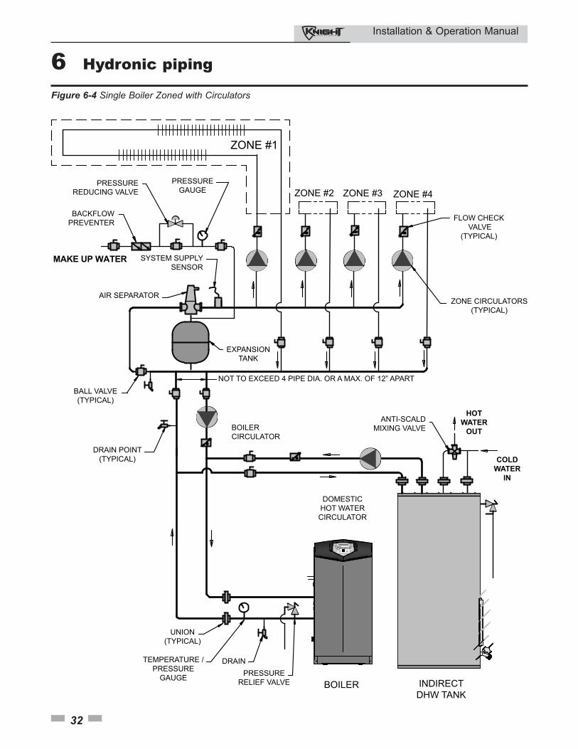
Installation & Operation Manual
32
6 Hydronic piping
BOILER
PRESSURE
REDUCING VALVE
BACKFLOW
PREVENTER
PRESSURE
GAUGE
SYSTEM SUPPLY
SENSOR
NOT TO EXCEED 4 PIPE DIA. OR A MAX. OF 12” APART
DRAIN POINT
(TYPICAL)
ANTI-SCALD
MIXING VALVE
DOMESTIC
HOT WATER
CIRCULATOR
PRESSURE
RELIEF VALVE
UNION
(TYPICAL)
TEMPERATURE /
PRESSURE
GAUGE
BOILER
CIRCULATOR
DRAIN
INDIRECT
DHW TANK
BALL VALVE
(TYPICAL)
EXPANSION
TANK
HOT
WATER
OUT
ZONE #1
ZONE #2 ZONE #3 ZONE #4
AIR SEPARATOR
COLD
WATER
IN
FLOW CHECK
VALVE
(TYPICAL)
MAKE UP WATER
ZONE CIRCULATORS
(TYPICAL)
Figure 6-4 Single Boiler Zoned with Circulators
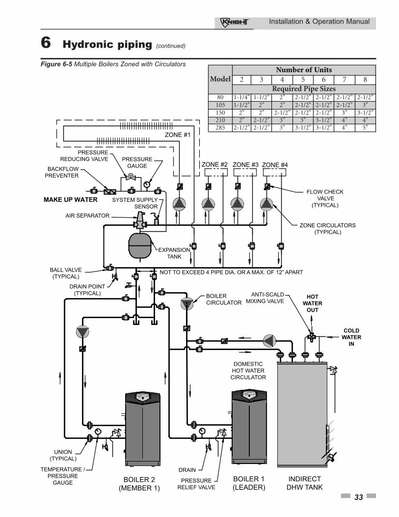
Installation & Operation Manual
33
6 Hydronic piping (continued)
BOILER 1
(LEADER)
PRESSURE
REDUCING VALVE
BACKFLOW
PREVENTER
PRESSURE
GAUGE
SYSTEM SUPPLY
SENSOR
NOT TO EXCEED 4 PIPE DIA. OR A MAX. OF 12” APART
DRAIN POINT
(TYPICAL) ANTI-SCALD
MIXING VALVE
DOMESTIC
HOT WATER
CIRCULATOR
PRESSURE
RELIEF VALVE
UNION
(TYPICAL)
TEMPERATURE /
PRESSURE
GAUGE
BOILER
CIRCULATOR
DRAIN
INDIRECT
DHW TANK
BALL VALVE
(TYPICAL)
EXPANSION
TANK
HOT
WATER
OUT
ZONE #1
ZONE #2 ZONE #3 ZONE #4
AIR SEPARATOR
COLD
WATER
IN
FLOW CHECK
VALVE
(TYPICAL)MAKE UP WATER
ZONE CIRCULATORS
(TYPICAL)
BOILER 2
(MEMBER 1)
Figure 6-5 Multiple Boilers Zoned with Circulators
ModelNumber of Units
2 3 4 5 6 7 8Required Pipe Sizes
80 1-1/4" 1-1/2" 2" 2-1/2" 2-1/2" 2-1/2" 2-1/2"105 1-1/2" 2" 2" 2-1/2" 2-1/2" 2-1/2" 3"150 2" 2" 2-1/2" 2-1/2" 2-1/2" 3" 3-1/2"210 2" 2-1/2" 3" 3" 3-1/2" 4" 4"285 2-1/2" 2-1/2" 3" 3-1/2" 3-1/2" 4" 5"
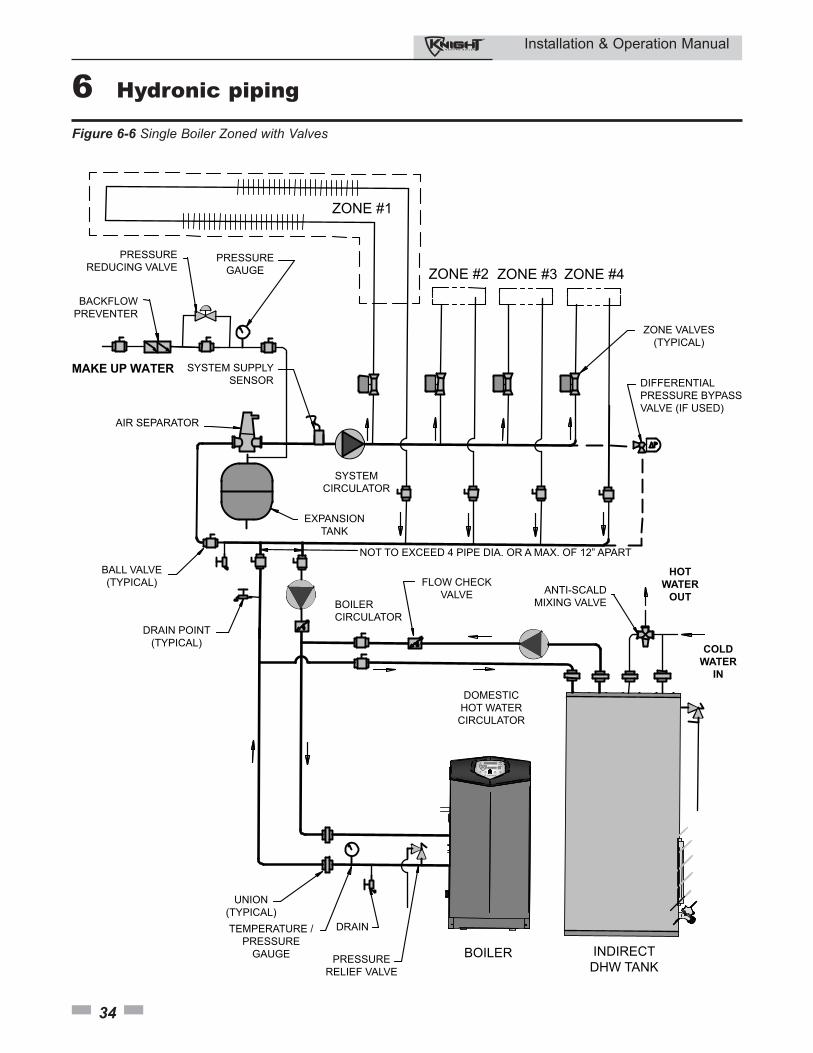
Installation & Operation Manual
34
6 Hydronic piping
PRESSURE
REDUCING VALVE
BACKFLOW
PREVENTER
PRESSURE
GAUGE
SYSTEM SUPPLY
SENSOR
NOT TO EXCEED 4 PIPE DIA. OR A MAX. OF 12” APART
DRAIN POINT
(TYPICAL)
SYSTEM
CIRCULATOR
ANTI-SCALD
MIXING VALVE
DOMESTIC
HOT WATER
CIRCULATOR
PRESSURE
RELIEF VALVE
UNION
(TYPICAL)
TEMPERATURE /
PRESSURE
GAUGE
BOILER
CIRCULATOR
DRAIN
BOILER INDIRECT
DHW TANK
BALL VALVE
(TYPICAL)
EXPANSION
TANK
HOT
WATER
OUT
ZONE #1
ZONE #2 ZONE #3 ZONE #4
AIR SEPARATOR
COLD
WATER
IN
FLOW CHECK
VALVE
ZONE VALVES
(TYPICAL)
DIFFERENTIAL
PRESSURE BYPASS
VALVE (IF USED)
MAKE UP WATER
Figure 6-6 Single Boiler Zoned with Valves
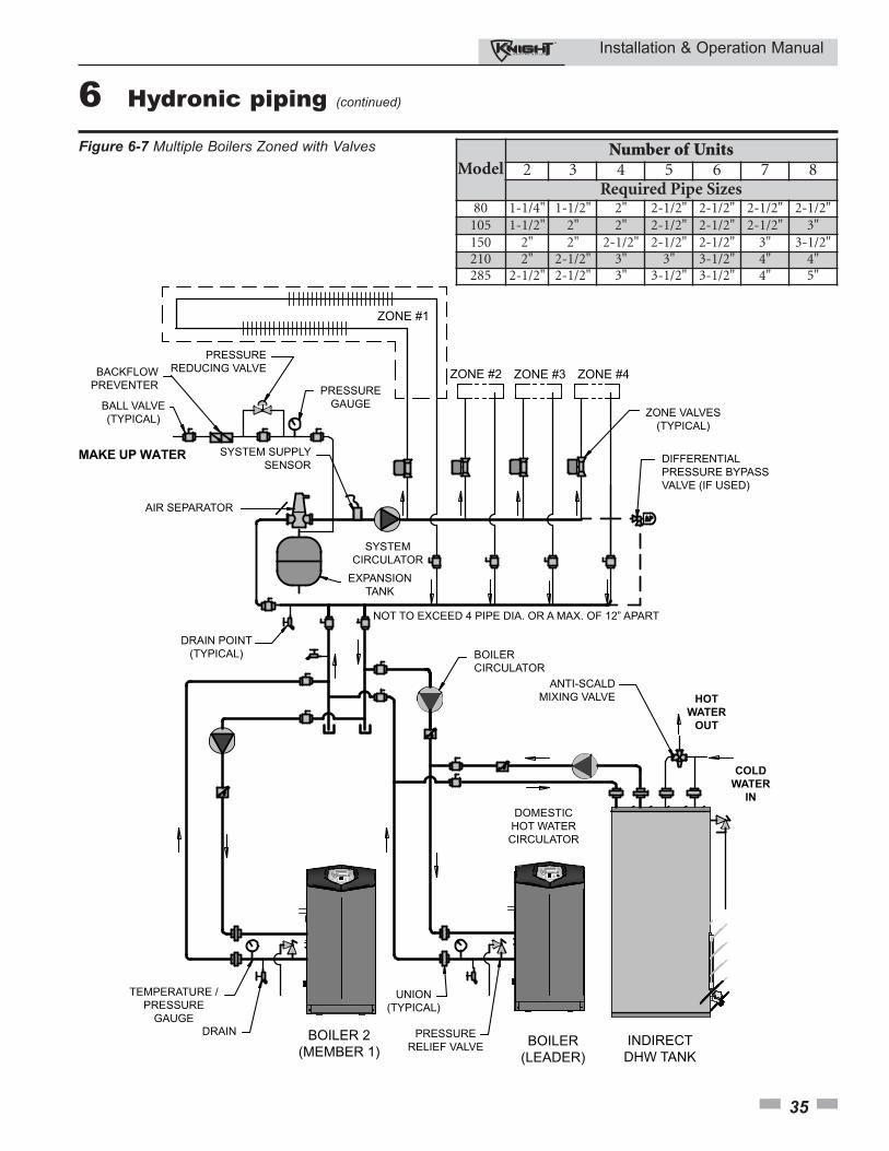
Installation & Operation Manual
35
6 Hydronic piping (continued)
PRESSURE
REDUCING VALVEBACKFLOW
PREVENTERPRESSURE
GAUGE
SYSTEM SUPPLY
SENSOR
NOT TO EXCEED 4 PIPE DIA. OR A MAX. OF 12” APART
DRAIN POINT
(TYPICAL)
SYSTEM
CIRCULATOR
ANTI-SCALD
MIXING VALVE
DOMESTIC
HOT WATER
CIRCULATOR
PRESSURE
RELIEF VALVE
UNION
(TYPICAL)
TEMPERATURE /
PRESSURE
GAUGE
BOILER
CIRCULATOR
DRAINBOILER
(LEADER)
INDIRECT
DHW TANK
BALL VALVE
(TYPICAL)
EXPANSION
TANK
HOT
WATER
OUT
ZONE #1
ZONE #2 ZONE #3 ZONE #4
AIR SEPARATOR
COLD
WATER
IN
ZONE VALVES
(TYPICAL)
DIFFERENTIAL
PRESSURE BYPASS
VALVE (IF USED)
MAKE UP WATER
BOILER 2
(MEMBER 1)
Figure 6-7 Multiple Boilers Zoned with ValvesModel
Number of Units2 3 4 5 6 7 8
Required Pipe Sizes80 1-1/4" 1-1/2" 2" 2-1/2" 2-1/2" 2-1/2" 2-1/2"
105 1-1/2" 2" 2" 2-1/2" 2-1/2" 2-1/2" 3"150 2" 2" 2-1/2" 2-1/2" 2-1/2" 3" 3-1/2"210 2" 2-1/2" 3" 3" 3-1/2" 4" 4"285 2-1/2" 2-1/2" 3" 3-1/2" 3-1/2" 4" 5"
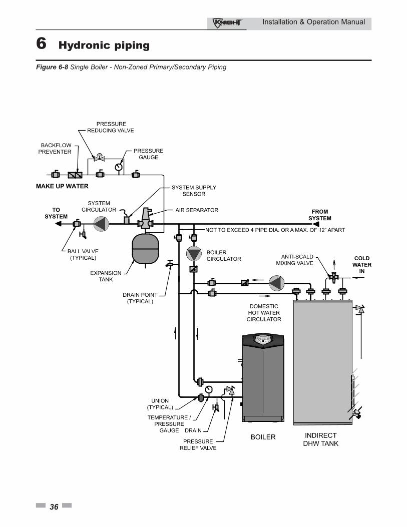
Installation & Operation Manual
36
6 Hydronic piping
BOILER
TO
SYSTEM
PRESSURE
REDUCING VALVE
BACKFLOW
PREVENTER PRESSURE
GAUGE
SYSTEM SUPPLY
SENSOR
NOT TO EXCEED 4 PIPE DIA. OR A MAX. OF 12” APART
DRAIN POINT
(TYPICAL)
SYSTEM
CIRCULATOR
ANTI-SCALD
MIXING VALVE
DOMESTIC
HOT WATER
CIRCULATOR
PRESSURE
RELIEF VALVE
UNION
(TYPICAL)
TEMPERATURE /
PRESSURE
GAUGE
BOILER
CIRCULATOR
DRAININDIRECT
DHW TANK
BALL VALVE
(TYPICAL)
EXPANSION
TANK
AIR SEPARATOR
COLD
WATER
IN
MAKE UP WATER
FROM
SYSTEM
Figure 6-8 Single Boiler - Non-Zoned Primary/Secondary Piping
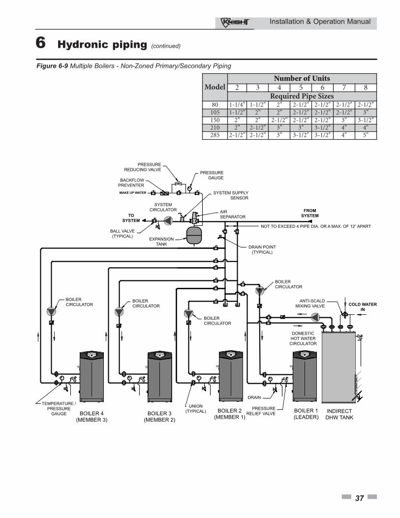
Installation & Operation Manual
37
6 Hydronic piping (continued)
PRESSURE
REDUCING VALVE
BACKFLOW
PREVENTER
PRESSURE
GAUGE
SYSTEM SUPPLY
SENSOR
AIR
SEPARATOR
FROM
SYSTEM
NOT TO EXCEED 4 PIPE DIA. OR A MAX. OF 12” APART
DRAIN POINT
(TYPICAL)
BOILER
CIRCULATOR
ANTI-SCALD
MIXING VALVE
DOMESTIC
HOT WATER
CIRCULATOR
COLD WATER
IN
PRESSURE
RELIEF VALVE
UNION
(TYPICAL)
TEMPERATURE /
PRESSURE
GAUGE
BOILER
CIRCULATORBOILER
CIRCULATOR
BOILER
CIRCULATOR
DRAIN
BOILER 2
(MEMBER 1)
BOILER 1
(LEADER)INDIRECT
DHW TANKBOILER 3
(MEMBER 2)
BOILER 4
(MEMBER 3)
SYSTEM
CIRCULATOR
BALL VALVE
(TYPICAL)EXPANSION
TANK
TO
SYSTEM
MAKE UP WATER
Figure 6-9 Multiple Boilers - Non-Zoned Primary/Secondary Piping
ModelNumber of Units
2 3 4 5 6 7 8Required Pipe Sizes
80 1-1/4" 1-1/2" 2" 2-1/2" 2-1/2" 2-1/2" 2-1/2"105 1-1/2" 2" 2" 2-1/2" 2-1/2" 2-1/2" 3"150 2" 2" 2-1/2" 2-1/2" 2-1/2" 3" 3-1/2"210 2" 2-1/2" 3" 3" 3-1/2" 4" 4"285 2-1/2" 2-1/2" 3" 3-1/2" 3-1/2" 4" 5"
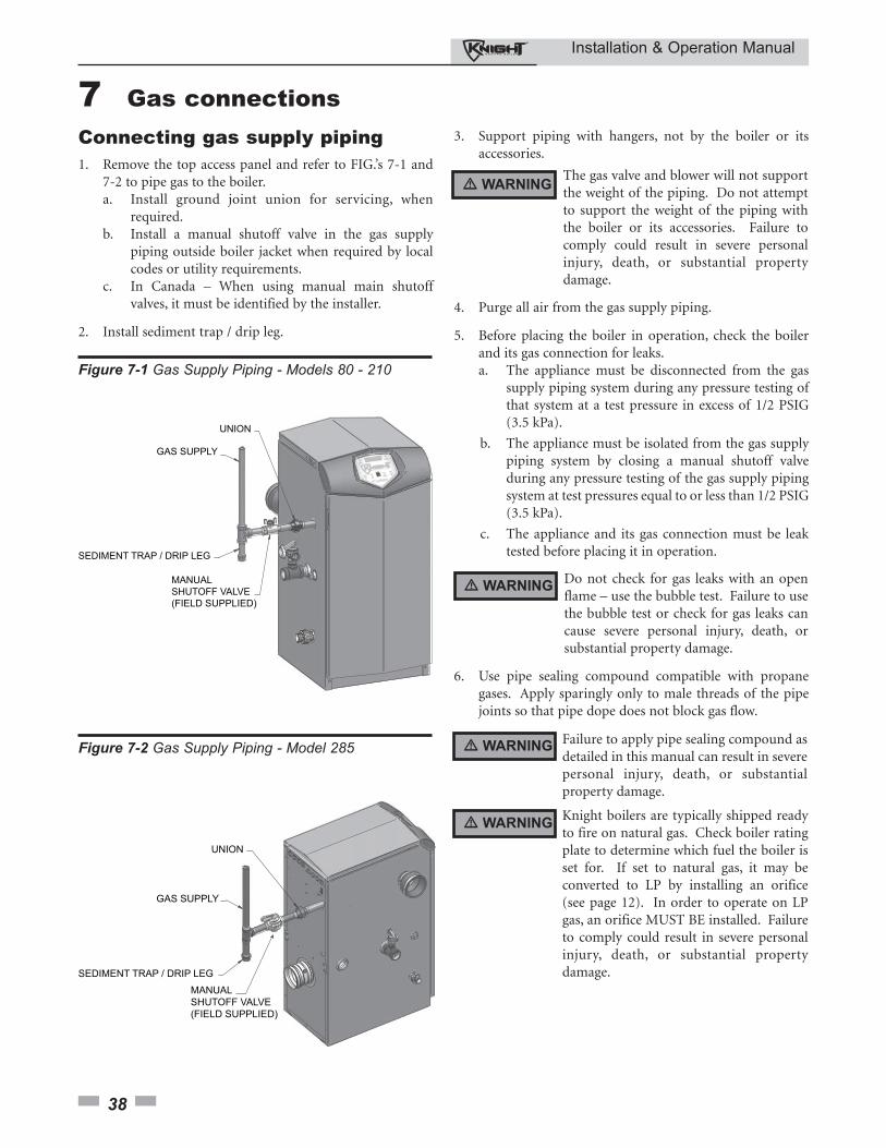
Installation & Operation Manual
38
7 Gas connectionsConnecting gas supply piping1. Remove the top access panel and refer to FIG.’s 7-1 and
7-2 to pipe gas to the boiler.a. Install ground joint union for servicing, when
required. b. Install a manual shutoff valve in the gas supply
piping outside boiler jacket when required by local codes or utility requirements.
c. In Canada – When using manual main shutoff valves, it must be identified by the installer.
2. Install sediment trap / drip leg.
SEDIMENT TRAP / DRIP LEG
Figure 7-1 Gas Supply Piping - Models 80 - 210
3. Support piping with hangers, not by the boiler or itsaccessories.
Do not check for gas leaks with an openflame – use the bubble test. Failure to usethe bubble test or check for gas leaks cancause severe personal injury, death, orsubstantial property damage.
4. Purge all air from the gas supply piping.
5. Before placing the boiler in operation, check the boilerand its gas connection for leaks.a. The appliance must be disconnected from the gas
supply piping system during any pressure testing of that system at a test pressure in excess of 1/2 PSIG (3.5 kPa).
b. The appliance must be isolated from the gas supply piping system by closing a manual shutoff valve during any pressure testing of the gas supply piping system at test pressures equal to or less than 1/2 PSIG (3.5 kPa).
c. The appliance and its gas connection must be leak tested before placing it in operation.
The gas valve and blower will not supportthe weight of the piping. Do not attemptto support the weight of the piping withthe boiler or its accessories. Failure tocomply could result in severe personalinjury, death, or substantial propertydamage.
� WARNING
� WARNING
6. Use pipe sealing compound compatible with propanegases. Apply sparingly only to male threads of the pipejoints so that pipe dope does not block gas flow.
SEDIMENT TRAP / DRIP LEG
Figure 7-2 Gas Supply Piping - Model 285 Failure to apply pipe sealing compound asdetailed in this manual can result in severepersonal injury, death, or substantialproperty damage.
Knight boilers are typically shipped readyto fire on natural gas. Check boiler ratingplate to determine which fuel the boiler isset for. If set to natural gas, it may beconverted to LP by installing an orifice(see page 12). In order to operate on LPgas, an orifice MUST BE installed. Failureto comply could result in severe personalinjury, death, or substantial propertydamage.
� WARNING
� WARNING
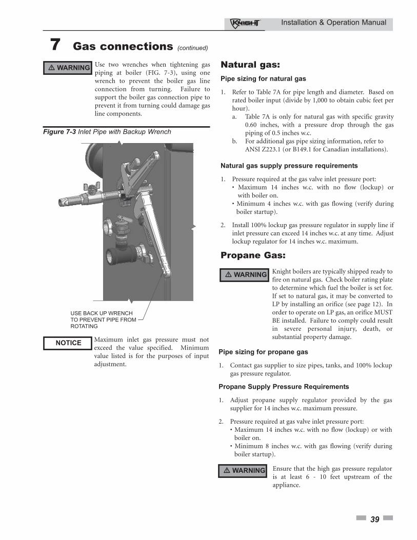
Installation & Operation Manual
39
7 Gas connections (continued)
Use two wrenches when tightening gaspiping at boiler (FIG. 7-3), using onewrench to prevent the boiler gas lineconnection from turning. Failure tosupport the boiler gas connection pipe toprevent it from turning could damage gasline components.
Figure 7-3 Inlet Pipe with Backup Wrench
Natural gas:Pipe sizing for natural gas
1. Refer to Table 7A for pipe length and diameter. Based onrated boiler input (divide by 1,000 to obtain cubic feet perhour).a. Table 7A is only for natural gas with specific gravity
0.60 inches, with a pressure drop through the gas piping of 0.5 inches w.c.
b. For additional gas pipe sizing information, refer to ANSI Z223.1 (or B149.1 for Canadian installations).
Natural gas supply pressure requirements
1. Pressure required at the gas valve inlet pressure port:• Maximum 14 inches w.c. with no flow (lockup) or
with boiler on.• Minimum 4 inches w.c. with gas flowing (verify during
boiler startup).
2. Install 100% lockup gas pressure regulator in supply line ifinlet pressure can exceed 14 inches w.c. at any time. Adjustlockup regulator for 14 inches w.c. maximum.
Propane Gas:
Pipe sizing for propane gas
1. Contact gas supplier to size pipes, tanks, and 100% lockupgas pressure regulator.
Propane Supply Pressure Requirements
1. Adjust propane supply regulator provided by the gassupplier for 14 inches w.c. maximum pressure.
2. Pressure required at gas valve inlet pressure port:• Maximum 14 inches w.c. with no flow (lockup) or with
boiler on.• Minimum 8 inches w.c. with gas flowing (verify during
boiler startup).
Maximum inlet gas pressure must notexceed the value specified. Minimumvalue listed is for the purposes of inputadjustment.
� WARNING
� WARNING
NOTICE
� WARNING Ensure that the high gas pressure regulatoris at least 6 - 10 feet upstream of theappliance.
Knight boilers are typically shipped ready tofire on natural gas. Check boiler rating plateto determine which fuel the boiler is set for.If set to natural gas, it may be converted toLP by installing an orifice (see page 12). Inorder to operate on LP gas, an orifice MUSTBE installed. Failure to comply could resultin severe personal injury, death, orsubstantial property damage.
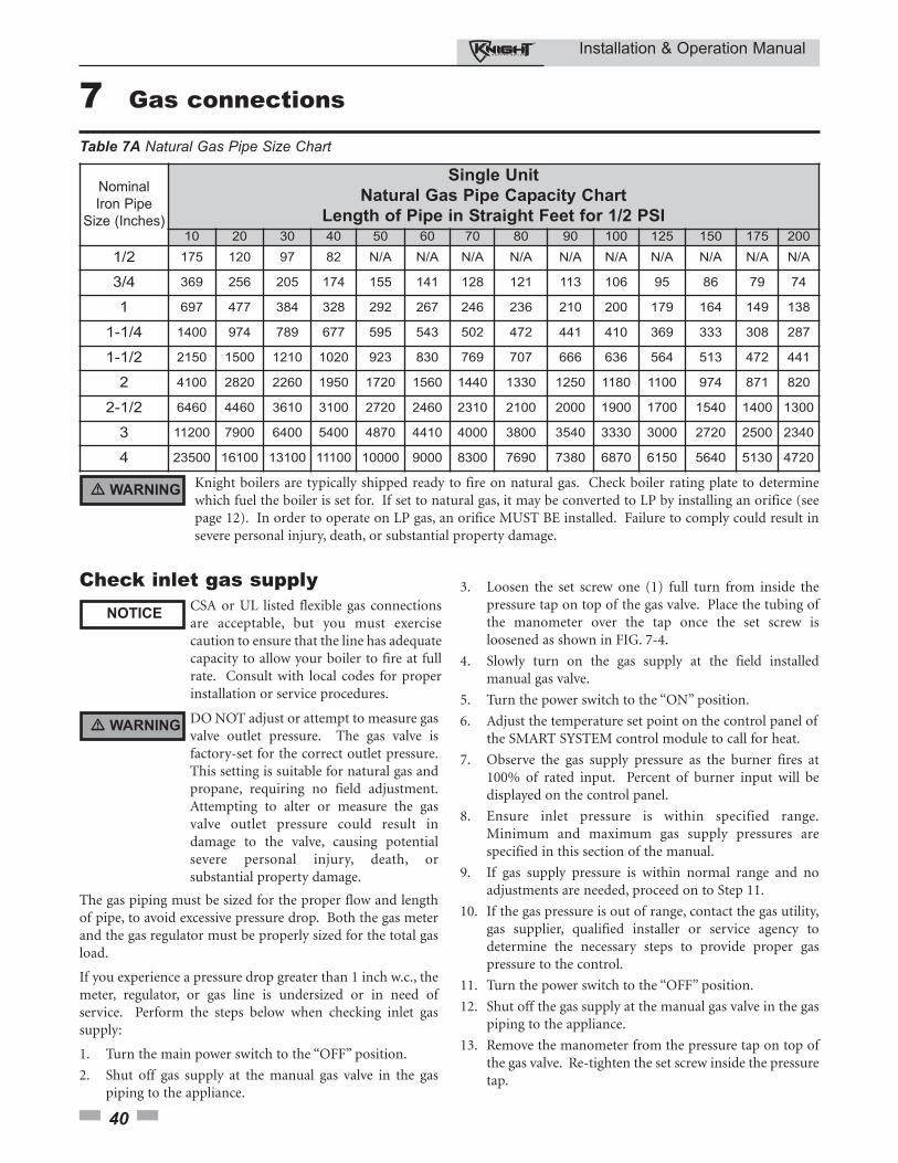
Installation & Operation Manual
40
7 Gas connections
Nominal
Iron Pipe
Size (Inches)
Single Unit
Natural Gas Pipe Capacity Chart
Length of Pipe in Straight Feet for 1/2 PSI10 20 30 40 50 60 70 80 90 100 125 150 175 200
1/2 175 120 97 82 N/A N/A N/A N/A N/A N/A N/A N/A N/A N/A
3/4 369 256 205 174 155 141 128 121 113 106 95 86 79 74
1 697 477 384 328 292 267 246 236 210 200 179 164 149 138
1-1/4 1400 974 789 677 595 543 502 472 441 410 369 333 308 287
1-1/2 2150 1500 1210 1020 923 830 769 707 666 636 564 513 472 441
2 4100 2820 2260 1950 1720 1560 1440 1330 1250 1180 1100 974 871 820
2-1/2 6460 4460 3610 3100 2720 2460 2310 2100 2000 1900 1700 1540 1400 1300
3 11200 7900 6400 5400 4870 4410 4000 3800 3540 3330 3000 2720 2500 2340
4 23500 16100 13100 11100 10000 9000 8300 7690 7380 6870 6150 5640 5130 4720
Knight boilers are typically shipped ready to fire on natural gas. Check boiler rating plate to determinewhich fuel the boiler is set for. If set to natural gas, it may be converted to LP by installing an orifice (seepage 12). In order to operate on LP gas, an orifice MUST BE installed. Failure to comply could result insevere personal injury, death, or substantial property damage.
Table 7A Natural Gas Pipe Size Chart
The gas piping must be sized for the proper flow and lengthof pipe, to avoid excessive pressure drop. Both the gas meterand the gas regulator must be properly sized for the total gasload.
If you experience a pressure drop greater than 1 inch w.c., themeter, regulator, or gas line is undersized or in need ofservice. Perform the steps below when checking inlet gassupply:
1. Turn the main power switch to the “OFF” position.
2. Shut off gas supply at the manual gas valve in the gas piping to the appliance.
� WARNING
3. Loosen the set screw one (1) full turn from inside the pressure tap on top of the gas valve. Place the tubing of the manometer over the tap once the set screw is loosened as shown in FIG. 7-4.
4. Slowly turn on the gas supply at the field installed manual gas valve.
5. Turn the power switch to the “ON” position.
6. Adjust the temperature set point on the control panel of the SMART SYSTEM control module to call for heat.
7. Observe the gas supply pressure as the burner fires at 100% of rated input. Percent of burner input will be displayed on the control panel.
8. Ensure inlet pressure is within specified range. Minimum and maximum gas supply pressures are specified in this section of the manual.
9. If gas supply pressure is within normal range and no adjustments are needed, proceed on to Step 11.
10. If the gas pressure is out of range, contact the gas utility, gas supplier, qualified installer or service agency to determine the necessary steps to provide proper gas pressure to the control.
11. Turn the power switch to the “OFF” position.
12. Shut off the gas supply at the manual gas valve in the gas piping to the appliance.
13. Remove the manometer from the pressure tap on top of the gas valve. Re-tighten the set screw inside the pressure tap.
Check inlet gas supplyNOTICE
CSA or UL listed flexible gas connectionsare acceptable, but you must exercisecaution to ensure that the line has adequatecapacity to allow your boiler to fire at fullrate. Consult with local codes for properinstallation or service procedures.
DO NOT adjust or attempt to measure gasvalve outlet pressure. The gas valve isfactory-set for the correct outlet pressure.This setting is suitable for natural gas andpropane, requiring no field adjustment.Attempting to alter or measure the gasvalve outlet pressure could result indamage to the valve, causing potentialsevere personal injury, death, orsubstantial property damage.
� WARNING
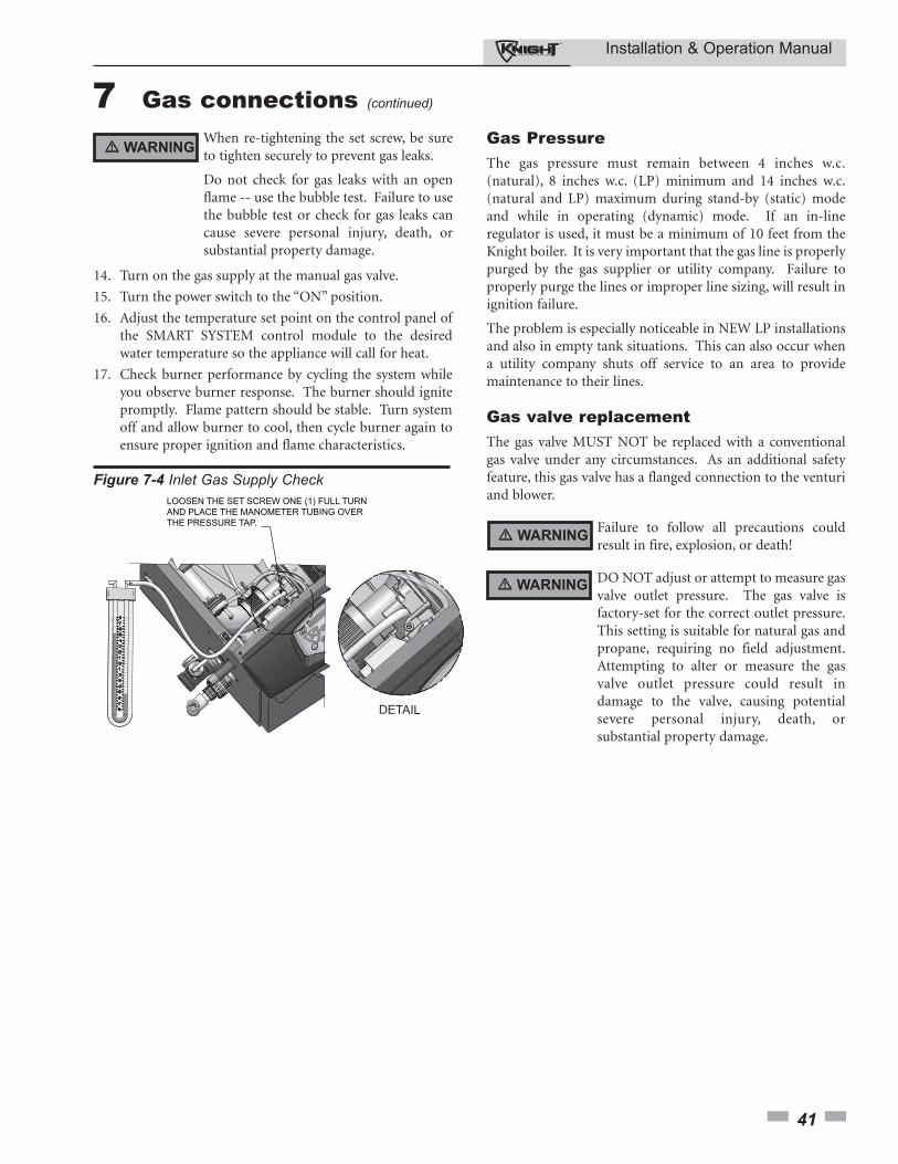
Installation & Operation Manual
41
7 Gas connections (continued)
� WARNINGWhen re-tightening the set screw, be sureto tighten securely to prevent gas leaks.
Do not check for gas leaks with an openflame -- use the bubble test. Failure to usethe bubble test or check for gas leaks cancause severe personal injury, death, orsubstantial property damage.
14. Turn on the gas supply at the manual gas valve.
15. Turn the power switch to the “ON” position.
16. Adjust the temperature set point on the control panel of the SMART SYSTEM control module to the desired water temperature so the appliance will call for heat.
17. Check burner performance by cycling the system while you observe burner response. The burner should ignite promptly. Flame pattern should be stable. Turn system off and allow burner to cool, then cycle burner again to ensure proper ignition and flame characteristics.
Gas PressureThe gas pressure must remain between 4 inches w.c.(natural), 8 inches w.c. (LP) minimum and 14 inches w.c.(natural and LP) maximum during stand-by (static) modeand while in operating (dynamic) mode. If an in-lineregulator is used, it must be a minimum of 10 feet from theKnight boiler. It is very important that the gas line is properlypurged by the gas supplier or utility company. Failure toproperly purge the lines or improper line sizing, will result inignition failure.
The problem is especially noticeable in NEW LP installationsand also in empty tank situations. This can also occur whena utility company shuts off service to an area to providemaintenance to their lines.
Gas valve replacementThe gas valve MUST NOT be replaced with a conventionalgas valve under any circumstances. As an additional safetyfeature, this gas valve has a flanged connection to the venturiand blower.
DETAIL
LOOSEN THE SET SCREW ONE (1) FULL TURNAND PLACE THE MANOMETER TUBING OVERTHE PRESSURE TAP.
Figure 7-4 Inlet Gas Supply Check
DO NOT adjust or attempt to measure gasvalve outlet pressure. The gas valve isfactory-set for the correct outlet pressure.This setting is suitable for natural gas andpropane, requiring no field adjustment.Attempting to alter or measure the gasvalve outlet pressure could result indamage to the valve, causing potentialsevere personal injury, death, orsubstantial property damage.
Failure to follow all precautions couldresult in fire, explosion, or death!
� WARNING
� WARNING
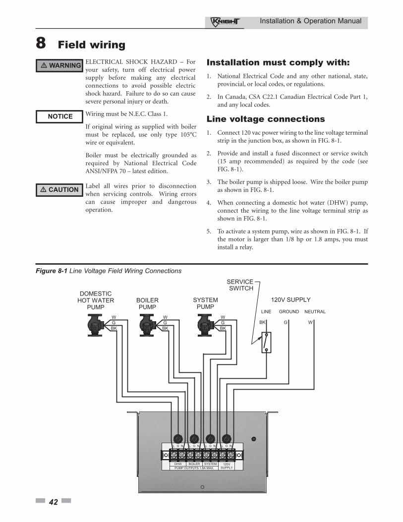
Installation & Operation Manual
42
8 Field wiring ELECTRICAL SHOCK HAZARD – Foryour safety, turn off electrical powersupply before making any electricalconnections to avoid possible electricshock hazard. Failure to do so can causesevere personal injury or death.
Wiring must be N.E.C. Class 1.
If original wiring as supplied with boilermust be replaced, use only type 105°Cwire or equivalent.
Boiler must be electrically grounded asrequired by National Electrical CodeANSI/NFPA 70 – latest edition.
Installation must comply with:1. National Electrical Code and any other national, state,
provincial, or local codes, or regulations.
2. In Canada, CSA C22.1 Canadian Electrical Code Part 1,and any local codes.
Line voltage connections1. Connect 120 vac power wiring to the line voltage terminal
strip in the junction box, as shown in FIG. 8-1.
2. Provide and install a fused disconnect or service switch(15 amp recommended) as required by the code (seeFIG. 8-1).
3. The boiler pump is shipped loose. Wire the boiler pumpas shown in FIG. 8-1.
4. When connecting a domestic hot water (DHW) pump,connect the wiring to the line voltage terminal strip asshown in FIG. 8-1.
5. To activate a system pump, wire as shown in FIG. 8-1. Ifthe motor is larger than 1/8 hp or 1.8 amps, you mustinstall a relay.
Figure 8-1 Line Voltage Field Wiring Connections
Label all wires prior to disconnectionwhen servicing controls. Wiring errorscan cause improper and dangerousoperation.
� WARNING
NOTICE
� CAUTION
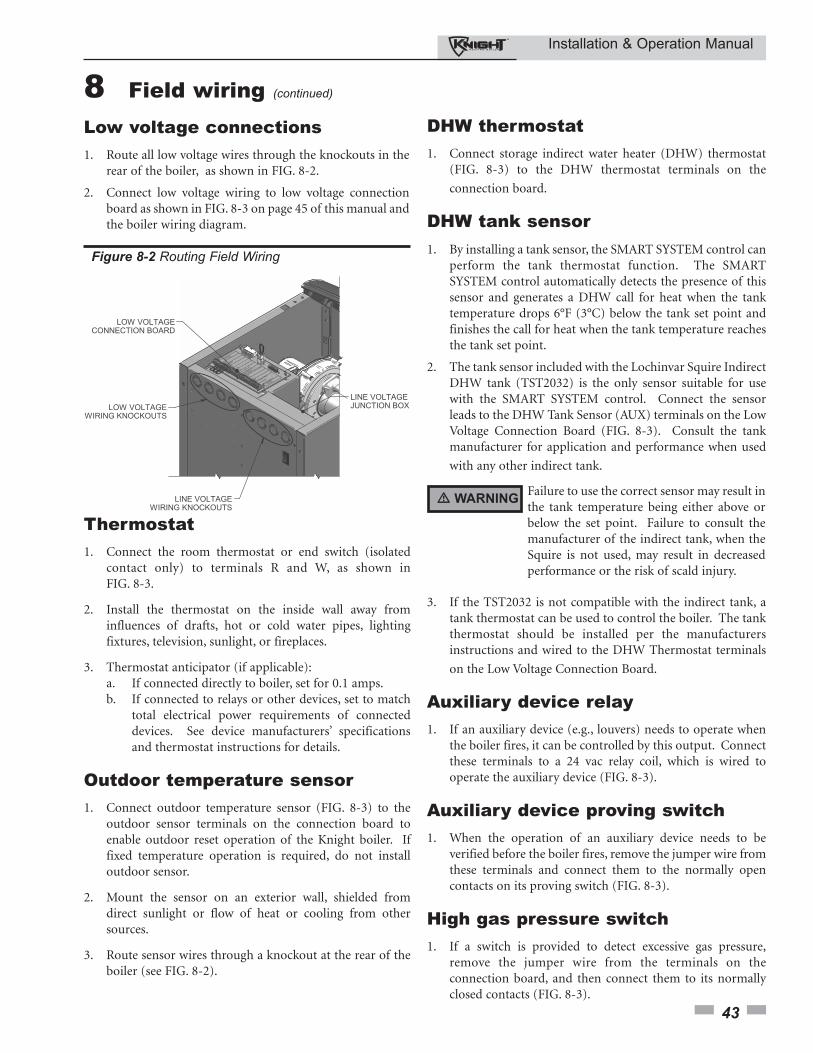
Installation & Operation Manual
43
Low voltage connections 1. Route all low voltage wires through the knockouts in the
rear of the boiler, as shown in FIG. 8-2.
2. Connect low voltage wiring to low voltage connectionboard as shown in FIG. 8-3 on page 45 of this manual andthe boiler wiring diagram.
Figure 8-2 Routing Field Wiring
8 Field wiring (continued)
Thermostat1. Connect the room thermostat or end switch (isolated
contact only) to terminals R and W, as shown inFIG. 8-3.
2. Install the thermostat on the inside wall away frominfluences of drafts, hot or cold water pipes, lightingfixtures, television, sunlight, or fireplaces.
3. Thermostat anticipator (if applicable):a. If connected directly to boiler, set for 0.1 amps.b. If connected to relays or other devices, set to match
total electrical power requirements of connected devices. See device manufacturers’ specifications and thermostat instructions for details.
Outdoor temperature sensor1. Connect outdoor temperature sensor (FIG. 8-3) to the
outdoor sensor terminals on the connection board toenable outdoor reset operation of the Knight boiler. Iffixed temperature operation is required, do not installoutdoor sensor.
2. Mount the sensor on an exterior wall, shielded fromdirect sunlight or flow of heat or cooling from othersources.
3. Route sensor wires through a knockout at the rear of theboiler (see FIG. 8-2).
DHW thermostat1. Connect storage indirect water heater (DHW) thermostat
(FIG. 8-3) to the DHW thermostat terminals on the
connection board.
DHW tank sensor1. By installing a tank sensor, the SMART SYSTEM control can
perform the tank thermostat function. The SMARTSYSTEM control automatically detects the presence of thissensor and generates a DHW call for heat when the tanktemperature drops 6°F (3°C) below the tank set point andfinishes the call for heat when the tank temperature reachesthe tank set point.
2. The tank sensor included with the Lochinvar Squire IndirectDHW tank (TST2032) is the only sensor suitable for usewith the SMART SYSTEM control. Connect the sensorleads to the DHW Tank Sensor (AUX) terminals on the LowVoltage Connection Board (FIG. 8-3). Consult the tankmanufacturer for application and performance when used
with any other indirect tank.
3. If the TST2032 is not compatible with the indirect tank, atank thermostat can be used to control the boiler. The tankthermostat should be installed per the manufacturersinstructions and wired to the DHW Thermostat terminals
on the Low Voltage Connection Board.
Auxiliary device relay1. If an auxiliary device (e.g., louvers) needs to operate when
the boiler fires, it can be controlled by this output. Connectthese terminals to a 24 vac relay coil, which is wired tooperate the auxiliary device (FIG. 8-3).
Auxiliary device proving switch1. When the operation of an auxiliary device needs to be
verified before the boiler fires, remove the jumper wire fromthese terminals and connect them to the normally opencontacts on its proving switch (FIG. 8-3).
High gas pressure switch1. If a switch is provided to detect excessive gas pressure,
remove the jumper wire from the terminals on theconnection board, and then connect them to its normallyclosed contacts (FIG. 8-3).
Failure to use the correct sensor may result inthe tank temperature being either above orbelow the set point. Failure to consult themanufacturer of the indirect tank, when theSquire is not used, may result in decreasedperformance or the risk of scald injury.
� WARNING
Installation & Operation Manual
44
8 Field wiring
System supply sensor1. By installing the system supply sensor into the supply of
the primary loop, the temperature of the primary supplycan be controlled. The SMART SYSTEM controlautomatically detects the presence of this sensor, andcontrols the boiler firing rate to maintain the systemsupply temperature to the set point (if the outlet sensorcontrol is currently selected). If it is desired to control thesystem return temperature, then program the SMARTSYSTEM control to use the inlet sensor as the controllingsensor. See the Knight Boiler Service Manual forinstructions on how to use the inlet sensor as thecontrolling sensor. When the inlet sensor is programmedas the controlling sensor, it is vital that the SYSTEMSUPPLY sensor be installed. DO NOT INSTALL THESYSTEM SUPPLY SENSOR INTO THE SYSTEMRETURN.
2. Connect these terminals to the system supply sensor(FIG. 8-3).
Boiler management system1. An external control may be connected to control either
the firing rate or the set point of the boiler. Connect theRoom Thermostat / Zone Control terminals to the enableoutput of the external control and connect the 0 - 10 vdcterminals to the 0 - 10 vdc output of the external control.
2. Make sure the ground terminal is connected to theground output terminal of the external control, and the0 - 10 vdc terminal is connected to the 0 - 10 vdc terminalof the external control.
Runtime contactsThe SMART SYSTEM control closes a set of dry contactswhenever the burner is running. This is typically used byBuilding Management Systems to verify that the boiler isresponding to a call for heat.
Alarm contactsThe SMART SYSTEM control closes another set of contactswhenever the boiler is locked out or the power is turned off.This can be used to turn on an alarm, or signal a BuildingManagement System that the boiler is down. Note that thesecontacts will close momentarily at the end of each call forheat.
Wiring of the cascadeWhen wiring the boilers for Cascade operation, select oneboiler as the Leader boiler. The remaining boilers will bedesignated as Members. See page 52 “Configuration of theCascade” for a detailed explanation of this procedure.
Connect the system supply sensor and outdoor air sensor (ifused) to the Leader boiler. For the Cascade system to workproperly the system supply sensor must be installed. Thelocation of the system supply sensor should be downstream ofthe boiler connections in the main system loop (FIG.’s 6-4,6-6, and 6-8). The system supply sensor should be wired to theLow Voltage Connection Board at the terminals marked forthe system supply sensor (see FIG. 8-3). The Leader controlwill use the water temperature at the system supply sensor tocontrol the operation of the Cascade.
If outdoor air reset is desired, the outdoor air sensor should bewired to the Low Voltage Connection Board at the terminalsmarked for the outdoor air sensor (FIG. 8-3). If the outdoorair sensor is connected, the Leader control will calculate thewater temperature set point based on the programmed resetcurve parameters. If the outdoor air sensor is not connected,the Leader control will maintain the fixed water temperatureset point that is programmed into the control.
If a Thermostat, Zone Control enable output, or BuildingManagement System enable output are available, it should bewired to the Low Voltage Connection Board on the Leaderboiler at the terminals marked for the RoomThermostat/Zone Control (FIG. 8-3). If the boilers are to runcontinuously, connect a jumper wire between the R and Wterminals for the Thermostat/Zone Control input. This willinitiate a call for heat on the Cascade.
Communication between the Leader boiler and the Memberboilers is accomplished by using shielded, 2-wire twisted paircommunication cable. Connect one of the twisted pair wiresto terminal A on each of the Low Voltage Connection boards,and the other wire of the twisted pair to terminal B on each ofthe Low Voltage Connection Boards. Connect the shield wiresto one of the shield ground terminals on the Low VoltageConnection Boards (FIG. 8-3). If more than two boilers are onthe Cascade, daisy chain the wiring from the Sequencingterminals on the second boiler to the Sequencing terminals onthe third boiler, then from the third to the forth, and so on.The connections between boilers can be made in any order,regardless of the addresses of the boilers. Try to keep eachcable as short as possible.
Low gas pressure switch1. If a switch is provided to detect low gas pressure, remove
the jumper wire from the terminals on the connectionboard and connect them to its normally open contacts(FIG. 8-3).
2. If both a high and low gas pressure switch is used, connecttheir respective contacts in series, and connect them tothe terminals on the connection board (FIG. 8-3).
Flow switch1. A flow switch is used to guarantee flow through the boiler
before allowing it to fire. The flow switch must beinstalled in line with the boiler.
2. Connect these terminals to the normally open contacts onthe flow switch (FIG. 8-3).
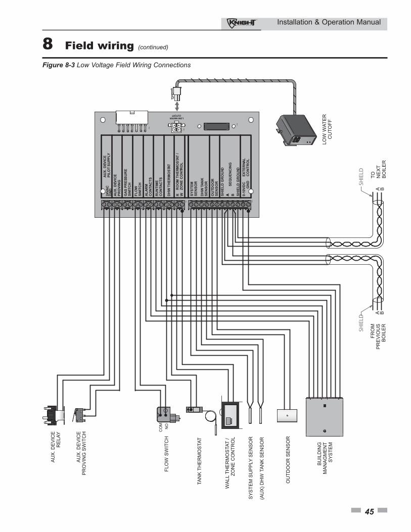
Installation & Operation Manual
45
8 Field wiring (continued)
AU
X. D
EV
ICE
PIL
OT S
UP
PLY
24V
AC
GN
D
AU
X. D
EV
ICE
PR
OV
ING
GA
S P
RE
SS
UR
ES
WIT
CH
FL
OW
SW
ITC
H
AL
AR
MC
ON
TA
CT
S
RU
NT
IME
CO
NTA
CT
S
SY
ST
EM
SE
NS
OR
DH
W T
AN
KS
EN
SO
R
OU
TD
OO
RS
EN
SO
R
SH
IEL
D G
RO
UN D
0-1
0V
DC
EX
TE
RN
AL
G
ND
C
ON
TR
OL
DH
W T
HE
RM
OS
TAT
R W
RO
OM
TH
ER
MO
STA
T /
ZO
NE
CO
NTR
OL
A B SH
IEL
D G
RO
UND
SE
QU
EN
CIN
G
LOW WATERCUTOFF
CN
1
CN
2
CN
3
CN
4
CN
5
AU
X. D
EVIC
ER
ELA
Y
FLO
W S
WIT
CH
TAN
K T
HE
RM
OS
TAT
WA
LL T
HE
RM
OS
TAT
/ZO
NE
CO
NTR
OL
SYS
TEM
SU
PPLY
SE
NS
OR
OU
TDO
OR
SE
NS
OR
BU
ILD
ING
MAN
AG
MEN
TS
YSTE
MLO
W W
ATE
RC
UTO
FF
AU
X. D
EVIC
EP
RO
VIN
G S
WIT
CH C
OM
NO
A
A
BA B
SHIELD
SHIELD
FRO
MP
RE
VIO
US
BO
ILE
R
TO NEX
TB
OIL
ER
(AU
X) D
HW
TAN
K S
EN
SO
R
Figure 8-3 Low Voltage Field Wiring Connections
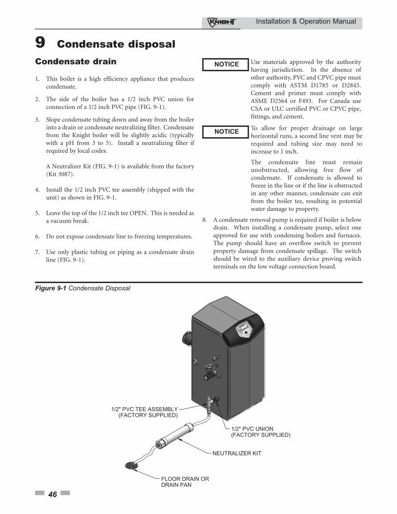
Installation & Operation Manual
46
9 Condensate disposalCondensate drain
1. This boiler is a high efficiency appliance that producescondensate.
2. The side of the boiler has a 1/2 inch PVC union forconnection of a 1/2 inch PVC pipe (FIG. 9-1).
3. Slope condensate tubing down and away from the boilerinto a drain or condensate neutralizing filter. Condensatefrom the Knight boiler will be slightly acidic (typicallywith a pH from 3 to 5). Install a neutralizing filter ifrequired by local codes.
A Neutralizer Kit (FIG. 9-1) is available from the factory(Kit 3087).
4. Install the 1/2 inch PVC tee assembly (shipped with theunit) as shown in FIG. 9-1.
5. Leave the top of the 1/2 inch tee OPEN. This is needed asa vacuum break.
6. Do not expose condensate line to freezing temperatures.
7. Use only plastic tubing or piping as a condensate drainline (FIG. 9-1).
Use materials approved by the authorityhaving jurisdiction. In the absence ofother authority, PVC and CPVC pipe mustcomply with ASTM D1785 or D2845.Cement and primer must comply withASME D2564 or F493. For Canada useCSA or ULC certified PVC or CPVC pipe,fittings, and cement.
8. A condensate removal pump is required if boiler is belowdrain. When installing a condensate pump, select oneapproved for use with condensing boilers and furnaces.The pump should have an overflow switch to preventproperty damage from condensate spillage. The switchshould be wired to the auxiliary device proving switchterminals on the low voltage connection board.
NOTICE
NOTICETo allow for proper drainage on largehorizontal runs, a second line vent may berequired and tubing size may need toincrease to 1 inch.
The condensate line must remainunobstructed, allowing free flow ofcondensate. If condensate is allowed tofreeze in the line or if the line is obstructedin any other manner, condensate can exitfrom the boiler tee, resulting in potentialwater damage to property.
Figure 9-1 Condensate Disposal
Installation & Operation Manual
47
10 Start-upCheck/control water chemistry
Do not use petroleum-based cleaning orsealing compounds in the boiler system.Damage to elastomer seals and gaskets inthe system could occur, resulting insubstantial property damage.
Hardness less than 7 grains
1. Consult local water treatment companies for hard waterareas (above 7 grains hardness).
Chlorine concentration less than 200 ppm
1. Do not fill boiler or operate with water containingchlorine in excess of 200 ppm.
2. Filling with chlorinated fresh water should be acceptablesince drinking water chlorine levels are much lower.
3. Do not use the boiler to directly heat swimming pool orspa water.
Test/replace freeze protection fluid
1. For systems using freeze protection fluids, follow fluidmanufacturer’s instructions.
2. Freeze protection fluid must be replaced periodically dueto degradation of inhibitors over time. Follow all fluidmanufacturer’s instructions.
Freeze protection (when used)1. Determine freeze protection fluid quantity using system
water content, following fluid manufacturer’sinstructions. Boiler water content is listed on page 7.Remember to include expansion tank water content.
2. Local codes may require a backflow preventer or actualdisconnect from city water supply.
3. When using freeze protection fluid with automatic fill,install a water meter to monitor water makeup. Freezeprotection fluid may leak before the water begins to leak,causing concentration to drop, reducing the freezeprotection level.
Fill and test water system1. Fill system only after ensuring the water meets the
requirements of this manual.
2. Close manual and automatic air vents and boiler drainvalve.
3. Fill to correct system pressure. Correct pressure will varywith each application.
a. The minimum cold water fill pressure for a residential system is 12 psi.
b. Pressure will rise when boiler is turned on and system water temperature increases.
Eliminate all system leaks. Continual freshmakeup water will reduce boiler life.Minerals can build up in the heatexchanger, reducing heat transfer,overheating the heat exchanger, andcausing heat exchanger failure.
Purge air from water system
1. Purge air from system:a. Connect a hose to the purge valve (see purge/drain
valves, in piping diagrams on pages 32 through 37). Route the hose to an area where water can drain and be seen.
b. Close the boiler or system isolation valve between the purge valve and fill connection to the system.
c. Close zone isolation valves.d. Open quick-fill valve on cold water makeup line.e. Open purge valve.f. One zone at a time, open the isolation valves. Allow
water to run through the zone, pushing out the air. Run until no noticeable air flow is present. Close the zone isolation valves and proceed with the next zone. Follow this procedure until all zones are purged.
g. Close the quick-fill water valve and purge valve and remove the hose. Open all isolation valves. Watch that system pressure rises to correct cold-fill pressure.
h. After the system has operated for a while, eliminate any residual air by using the manual air vents located throughout the system.
i. If purge valves are not installed in the system, open the manual air vents in the system one at a time, beginning with the lowest floor. Close the vent when water squirts out. Repeat with remaining vents.
2. Open automatic air vent (diaphragm-type or bladder-type expansion tank systems only) one turn.
3. Open other vents:a. Starting on the lowest floor, open air vents one at a
time until water squirts out.b. Repeat with remaining vents.
4. Refill to correct pressure.
4. At initial fill and during boiler startup and testing, checksystem thoroughly for any leaks. Repair all leaks beforeproceeding further.
� WARNING
� CAUTION
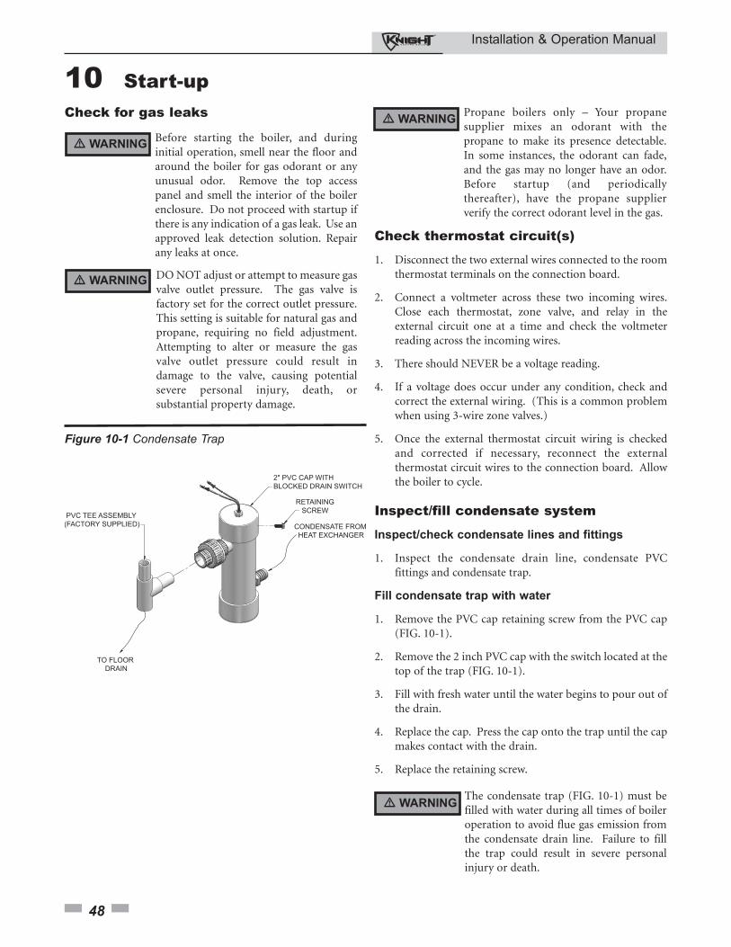
Installation & Operation Manual
48
10 Start-up Check for gas leaks
Before starting the boiler, and duringinitial operation, smell near the floor andaround the boiler for gas odorant or anyunusual odor. Remove the top accesspanel and smell the interior of the boilerenclosure. Do not proceed with startup ifthere is any indication of a gas leak. Use anapproved leak detection solution. Repairany leaks at once.
DO NOT adjust or attempt to measure gasvalve outlet pressure. The gas valve isfactory set for the correct outlet pressure.This setting is suitable for natural gas andpropane, requiring no field adjustment.Attempting to alter or measure the gasvalve outlet pressure could result indamage to the valve, causing potentialsevere personal injury, death, orsubstantial property damage.
Propane boilers only – Your propanesupplier mixes an odorant with thepropane to make its presence detectable.In some instances, the odorant can fade,and the gas may no longer have an odor.Before startup (and periodicallythereafter), have the propane supplierverify the correct odorant level in the gas.
Check thermostat circuit(s)
1. Disconnect the two external wires connected to the roomthermostat terminals on the connection board.
2. Connect a voltmeter across these two incoming wires.Close each thermostat, zone valve, and relay in theexternal circuit one at a time and check the voltmeterreading across the incoming wires.
3. There should NEVER be a voltage reading.
4. If a voltage does occur under any condition, check andcorrect the external wiring. (This is a common problemwhen using 3-wire zone valves.)
5. Once the external thermostat circuit wiring is checkedand corrected if necessary, reconnect the externalthermostat circuit wires to the connection board. Allowthe boiler to cycle.
Inspect/fill condensate system
Inspect/check condensate lines and fittings
1. Inspect the condensate drain line, condensate PVCfittings and condensate trap.
Fill condensate trap with water
1. Remove the PVC cap retaining screw from the PVC cap(FIG. 10-1).
2. Remove the 2 inch PVC cap with the switch located at thetop of the trap (FIG. 10-1).
3. Fill with fresh water until the water begins to pour out ofthe drain.
4. Replace the cap. Press the cap onto the trap until the capmakes contact with the drain.
5. Replace the retaining screw.
The condensate trap (FIG. 10-1) must befilled with water during all times of boileroperation to avoid flue gas emission fromthe condensate drain line. Failure to fillthe trap could result in severe personalinjury or death.
Figure 10-1 Condensate Trap
� WARNING
� WARNING
� WARNING
� WARNING
Installation & Operation Manual
49
10 Start-up (continued)
Final checks before starting the boiler
� Read the Knight Boiler Service Manual to familiarizeyourself with SMART SYSTEM control moduleoperation. Read this manual, page 50 for proper steps tostart boiler.
� Verify the boiler and system are full of water and allsystem components are correctly set for operation.
� Verify the preparation procedures of Section 10, pages 47and 48 have been completed.
� Fill the vent condensate trap with water (removing theretaining screw in order to remove the 2 inch PVC capwith the switch located at the top of the trap). Replacethe cap. Press the cap onto the trap until the cap makescontact with the drain. Replace the retaining screw.
� Verify electrical connections are correct and securelyattached.
� Inspect vent piping and air piping for signs ofdeterioration from corrosion, physical damage orsagging. Verify air piping and vent piping are intact andcorrectly installed per this manual.
Start the boiler
1. Read and follow the Operating instructions in FIG. 10-2,page 50.
If boiler does not start correctly
1. Check for loose connections, blown fuse or service switchoff?
2. Is external limit control (if used) open? Is boiler watertemperature above 200°F?
3. Is thermostat set below room temperature?
4. Is gas turned on at meter or boiler?
5. Is incoming gas pressure less than 4 inches w.c.?
If none of the above corrects the problem, refer to theTroubleshooting Section of the Knight Boiler Service Manual.
Check system and boiler
� Check water piping
1. Check system piping for leaks. If found, shut down theboiler and repair immediately. (See WARNINGS onpages 47 and 48 (startup) regarding failure to repairleaks.)
2. Vent any remaining air from the system using manualvents. Air in the system will interfere with circulation andcause heat distribution problems and noise.
� Check vent piping and air piping
1. Check for gastight seal at every connection, seam of airpiping, and vent piping.
Venting system must be sealed gastight toprevent flue gas spillage and carbonmonoxide emissions, which will result insevere personal injury or death.
� Check gas piping
1. Check around the boiler for gas odor following theprocedure on page 38 of this manual (connecting gas supplypiping).
If you discover evidence of any gas leak, shutdown the boiler at once. Find the leak sourcewith a bubble test and repair immediately.Do not start the boiler again until corrected.Failure to comply could result in severepersonal injury, death, or substantialproperty damage.
� Propane boilers – verify conversion
1. Verify propane conversion has been completed per thePropane Conversion instructions.
DO NOT adjust or attempt to measure gasvalve outlet pressure. The gas valve isfactory-set for the correct outlet pressure.This setting is suitable for natural gas andpropane, requiring no field adjustment.Attempting to alter or measure the gas valveoutlet pressure could result in damage to thevalve, causing potential severe personalinjury, death, or substantial propertydamage.
Check flame and combustion
1. Turn the main power off to the boiler by placing the“On/Off” switch in the OFF position.
2. Remove the flue temperature sensor from the flue pipeconnection. Note: Combustion measurements will bemade at this point.
3. Turn the main power on to the boiler by placing the“On/Off” switch in the ON position.
� WARNING
� WARNING
� WARNING
� WARNINGKnight boilers are typically shipped ready tofire on natural gas. Check boiler rating plateto determine which fuel the boiler is set for.If set to natural gas, it may be converted to LPby installing an orifice (see page 12). In orderto operate on LP gas, an orifice MUST BEinstalled. Failure to comply could result insevere personal injury, death, or substantialproperty damage.
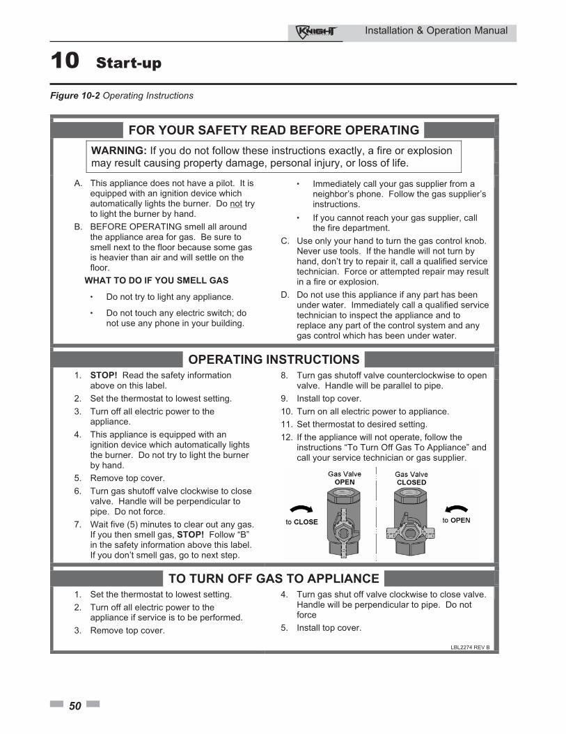
Installation & Operation Manual
50
10 Start-up
Figure 10-2 Operating Instructions
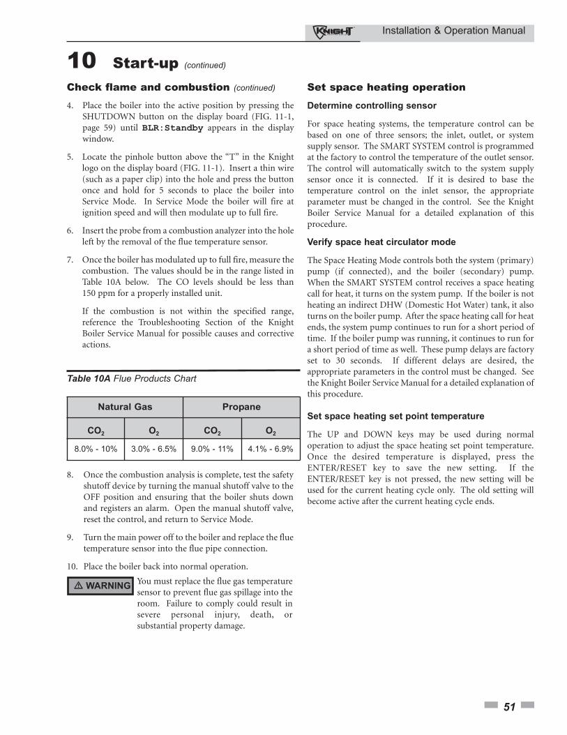
Installation & Operation Manual
51
Check flame and combustion (continued)
4. Place the boiler into the active position by pressing theSHUTDOWN button on the display board (FIG. 11-1,page 59) until BLR:Standby appears in the displaywindow.
5. Locate the pinhole button above the “T” in the Knightlogo on the display board (FIG. 11-1). Insert a thin wire(such as a paper clip) into the hole and press the buttononce and hold for 5 seconds to place the boiler intoService Mode. In Service Mode the boiler will fire atignition speed and will then modulate up to full fire.
6. Insert the probe from a combustion analyzer into the holeleft by the removal of the flue temperature sensor.
7. Once the boiler has modulated up to full fire, measure thecombustion. The values should be in the range listed inTable 10A below. The CO levels should be less than150 ppm for a properly installed unit.
If the combustion is not within the specified range,reference the Troubleshooting Section of the KnightBoiler Service Manual for possible causes and correctiveactions.
Set space heating operation
Determine controlling sensor
For space heating systems, the temperature control can bebased on one of three sensors; the inlet, outlet, or systemsupply sensor. The SMART SYSTEM control is programmedat the factory to control the temperature of the outlet sensor.The control will automatically switch to the system supplysensor once it is connected. If it is desired to base thetemperature control on the inlet sensor, the appropriateparameter must be changed in the control. See the KnightBoiler Service Manual for a detailed explanation of thisprocedure.
Verify space heat circulator mode
The Space Heating Mode controls both the system (primary)pump (if connected), and the boiler (secondary) pump.When the SMART SYSTEM control receives a space heatingcall for heat, it turns on the system pump. If the boiler is notheating an indirect DHW (Domestic Hot Water) tank, it alsoturns on the boiler pump. After the space heating call for heatends, the system pump continues to run for a short period oftime. If the boiler pump was running, it continues to run fora short period of time as well. These pump delays are factoryset to 30 seconds. If different delays are desired, theappropriate parameters in the control must be changed. Seethe Knight Boiler Service Manual for a detailed explanation ofthis procedure.
Set space heating set point temperature
The UP and DOWN keys may be used during normaloperation to adjust the space heating set point temperature.Once the desired temperature is displayed, press theENTER/RESET key to save the new setting. If theENTER/RESET key is not pressed, the new setting will beused for the current heating cycle only. The old setting willbecome active after the current heating cycle ends.
Table 10A Flue Products Chart
8. Once the combustion analysis is complete, test the safety shutoff device by turning the manual shutoff valve to the OFF position and ensuring that the boiler shuts down and registers an alarm. Open the manual shutoff valve, reset the control, and return to Service Mode.
9. Turn the main power off to the boiler and replace the flue temperature sensor into the flue pipe connection.
10. Place the boiler back into normal operation.
You must replace the flue gas temperaturesensor to prevent flue gas spillage into theroom. Failure to comply could result insevere personal injury, death, orsubstantial property damage.
� WARNING
Natural Gas Propane
CO2 O2 CO2 O2
8.0% - 10% 3.0% - 6.5% 9.0% - 11% 4.1% - 6.9%
10 Start-up (continued)
Installation & Operation Manual
52
10 Start-up Set domestic hot water (DHW) operation
Verify DHW circulator mode
The DHW Mode is programmed to heat an indirect domestichot water tank. When the tank thermostat calls for heat, theSMART SYSTEM control will turn on the DHW pump andturn off the boiler pump (if running). If the system pump isrunning, it will remain on. When the DHW call for heat ends,and there is no space heating call for heat, the DHW pumpwill continue to run for a period of time. This pump delay isset at the factory to 30 seconds. If a shorter or longer delay isdesired, the appropriate parameter in the control must bechanged. See the Knight Boiler Service Manual for a detailedexplanation of this procedure. If there is an active spaceheating call for heat, then the boiler pump will be turned onand the DHW pump will be turned off.
Set DHW target temperature
When in the DHW Mode, the control will modulate tomaintain the outlet temperature to a set point. This set pointis set at the factory to 180°F. If a different set point is desired,the appropriate parameter in the control must be changed.See the Knight Boiler Service Manual for a detailedexplanation of this procedure.
Set clock
The SMART SYSTEM control has a built-in clock that it usesfor its night setback feature and for logging events. This clockmust be set when the boiler is installed, and anytime theboiler has been powered off for more than one month. Usethe following procedure to set the clock:
1. Press and hold the MENU key for at least 5 seconds.
2. The display changes to ready “ENTER MENU CODE”, with four (4) zeros below it.
3. Change the zeros to match the user code (factory set at “0704”). Use the UP and DOWN keys to increment or decrement the flashing digit, and the NEXT and PREVIOUS keys to select which digit flashes.
4. Press the ENTER key.
5. The display changes to read USER CODE for a few seconds, then displays a menu.
6. Press the ENTER key.
7. Press the UP key twice to display “A3 DATE AND TIME”.
8. Press the ENTER key once.
9. The date and time are displayed as “YY:MM:DD W hh:mm”, where:mm: minuteshh: hour (24 hour time; e.g., 2:00 PM = 14:00)W: day of the week (1 = Sunday, 2 = Monday,
3 = Tuesday, etc.,)DD: dateMM: monthYY: year
NOTICEThe internal clock does not adjust forDaylight Savings Time and therefore,will require a manual adjustment.
Use the UP and DOWN keys to increment or decrement theflashing number, and the NEXT and PREVIOUS keys toselect which number flashes.
10. Press the ENTER key to save the setting.
11. Press the MENU key twice to exit the Programming Mode.
Configuration of the cascade
When installed in a Cascade system, the individual controlsmust be programmed for cascade operation. This isaccomplished by accessing the control parameters.
Input the Installer code as described in the Knight BoilerService Manual. Once the control parameters have beenaccessed, use the DOWN arrow key to select the H ControlMode parameters. Press the ENTER key to access theseparameters. Use the UP arrow key to access parameter H2 SHSource. Press the ENTER key to access this parameter. Use theDOWN arrow key to select Cascade. Press the ENTER key toprogram this into the control.
Press the UP arrow key to select the parameter H3 BLRAddress. Press the ENTER key to access this parameter. Eachunit in the Cascade system must be programmed with itsown address. The boiler designated as the Leader will have anaddress of 0. The remaining boilers in the Cascade will beMembers and have addresses from 1 - 7. Use the UP andDOWN arrow keys to select the appropriate address. Pressthe ENTER key to program this into the control.
Press the MENU key twice to exit the control parameters.Repeat this procedure for all boilers in the Cascade,designating the Leader control and the Member controls.
Installation & Operation Manual
53
11 Operating informationGeneral
How the boiler operates
The Knight boiler uses an advanced stainless steel heatexchanger and electronic control module that allows fullycondensing operation. The blower pulls in air and pushesflue products out of the boiler through the heat exchangerand flue piping. The control module regulates blower speedto control the boiler firing rate. The gas valve senses theamount of air flowing into the boiler and allows only the rightamount of gas to flow.
How the control module operates
The SMART SYSTEM control module receives input fromboiler sensors and external inputs. The control moduleactivates and controls the blower and gas valve to regulateheat input and switches the boiler, Domestic Hot Water(DHW), and system pumps on and off as needed. The userprograms the module to meet system needs by adjustingcontrol parameters. These parameters set operatingtemperatures and boiler operating modes. Boiler operationcan be based on boiler outlet water temperature, boiler inletwater temperature, or system temperature, depending on theparameter setting.
Control inputs and outputs
Room thermostat / zone control
This input tells the boiler to provide water for space heating.
Domestic Hot Water (DHW) tank thermostat
This input tells the boiler to provide water for heating anindirect DHW tank.
0 - 10V input (set point or power)
The Knight boiler can be controlled by a BuildingManagement System (BMS) using a 0 - 10 vdc signal. Thecontrol can be configured by the installer to use this signal toeither control set point or firing rate.
DHW priority
The SMART SYSTEM control module allows connection of aDHW thermostat to the low voltage connection board. Whenthe DHW thermostat calls for heat, the module activates theDHW pump, shuts down the boiler pump, and immediatelysets the target outlet water temperature to 180°F. Thisprovides automatic priority heat allocation to the` indirectwater heater for maximum response and recovery. The DHWpump continues for 30 seconds after the heating cycle todeliver the most possible heat.
DHW / space heating (SH) cycling
If a DHW call for heat is received while a space heating call isin progress, the control will start the DHW pump and shutthe boiler pump off. The system pump will remain on. If thespace heating call is still active while the DHW call is inoperation, the control will wait for 30 minutes (timeadjustable by installer) then it will switch back to the spaceheating demand. The control will switch back and forth untilone of the heat demands end.
Programmable controlling sensor
The control module is programmed to use the outlet sensoras the control sensor by default. If a system supply sensor isconnected, the control automatically uses it as the controlsensor. The control sensor can be changed by the installer tothe inlet sensor. If the inlet sensor is chosen as the controllingsensor, it is recommended that the system supply sensor beinstalled.
Anti-cycling
After a space heating demand has been satisfied, the controlwill delay the next space heating call for a set time period(time is adjustable by the installer). The time delay will bebypassed if the inlet water temperature drops too far duringthe delay.
Boiler, system, and DHW pump control
When a space heating call for heat starts and no DHW call ison, the system and boiler pumps are turned on. As long as thespace heating call for heat is on, the system pump will remainon. If a DHW call for heat is on, the boiler pump will wait toturn on until just before the DHW pump turns off. After thespace heating call for heat ends, both pumps will run for anadditional period of time.
When a DHW call for heat starts, the DHW pump is turnedon. If a space heating call for heat was on, the boiler pumpwill turn off a few seconds after the DHW pump turns on.
Temperature control
Modulation
The Knight boiler is capable of modulating its firing rate froma minimum of 20% to a maximum of 100%. The firing rateis dictated by the call for heat (i.e., space heating or domestichot water), the heating load, ramp delay (if enabled), andvarious other temperature limitations.

Installation & Operation Manual
54
11 Operating information Ramp delay
For systems with lower flow, the SMART SYSTEM can limitthe firing rate (when enabled) when a space heating call forheat starts, or when switching from a DHW call for heat to aspace heating call for heat. There are six (6) limits that can beprogrammed, as well as six (6) time intervals correspondingto each limit. The sixth limit will also limit the firing rate forthe rest of the call for heat.
Gradient limiting
If during operation of the boiler the outlet water temperatureis rising too quickly, the control will reduce the firing rate toits lowest setting.
Outdoor air reset
With the outdoor air sensor connected, the control modulewill calculate the set point based on the programmed resetcurve. The installer can change the slope of the reset curve byseveral adjustable parameters. The user can limit themaximum set point for the system using the space heating setpoint.
Boost function
If outdoor air reset is active, and a space heating demand hasbeen active continuously for a set period of time (timeadjustable by installer) and there has been no DHWdemands, the control will increase the set point by a fixednumber of degrees (adjustable by installer). This process willcontinue until the space heating demand ends, the set pointreaches the programmed set point or a maximum of 20increases has occurred. Once the system heat demand issatisfied, the set point will revert to the value determined bythe reset curve.
Night setback
The controller may be programmed to reduce the spaceheating set point during a certain time each day. A start andstop time can be programmed for each day of the week.
Flame current support
To prevent nuisance shutdowns when the boiler is firing atminimum rates, the control will increase the firing rate whenthe flame signal drops too low.
Protection features
Outlet temperature, flue temperature, and
temperature rise limiting
The outlet temperature is monitored by the boiler outlettemperature sensor. When the outlet temperature exceeds185°F, the unit will reduce the fan speed. If the outlet watertemperature exceeds 195°F the control will shut the unitdown until it cools off.
The control module monitors the flue temperature by asensor located in the flue exhaust. If the flue temperatureexceeds 215°F the control will reduce the maximum fanspeed. If the flue temperature exceeds 240°F the control willshut the unit down. The unit will restart automatically oncethe flue temperature drops 25°F and the minimum off timehas expired.
The control monitors the temperature difference between theinlet and the outlet sensor. If this difference exceeds 55°F thecontrol will reduce the fan speed. If the temperaturedifference exceeds 60°F the control will shut the unit down.The unit will restart automatically once the temperaturedifference has dropped below 55°F and the minimum off timehas expired.
Freeze protection
DO NOT install the boiler in a room likely to freeze.
The following integral feature of the SMART SYSTEMcontrol module provides some protection for the boiler only-- not for the system.
• The SMART SYSTEM control module provides freeze-up protection as follows when the boiler water temperature drops below 45°F:
• Below 45°F, the boiler and system pumps operate constantly.
• Below 37°F, the boiler turns on.• Boiler and pumps turn off if boiler water
temperature rises above 45°F.
This feature of the SMART SYSTEMcontrol module does not eliminate thepossibility of freezing. The installationmust still use recognized design,installation and maintenance practice toprevent freeze potential for the boiler andsystem.
� CAUTION
Installation & Operation Manual
55
High limit operations
When outlet temperature exceeds 200°F, high limit actionoccurs. The boiler shuts down until the outlet water coolsdown.
If local codes require manual reset, an Adjustable ManualReset High Limit Kit is available.
Low water cutoff protection
1. The SMART SYSTEM control module uses temperaturesensing of both supply and return areas of the heatexchanger. If the flow rate is too low or the outlettemperature too high, the control module modulates andshuts the boiler down. This ensures boiler shutdown inthe event of low water or low flow conditions.
2. Some codes and jurisdiction may accept these integralfeatures of the control in lieu of requiring an additionallimit control or low water cutoff. Consult localjurisdiction to determine. A low water cutoff kit(s) isavailable (Kit 3057).
Outdoor reset operation, if used
Target temperature with outdoor reset
This feature improves the system’s efficiency as the outdoortemperature warms up.
See the Knight Boiler Service Manual to change the settings.
Reset curve
The reset curve looks at outdoor air temperature and adjuststhe set point.
CascadeWhen multiple boilers are installed, they can be wiredtogether in a cascade sequence. A maximum of eight boilerscan be controlled from a single control. In this applicationone boiler would be designated as the Leader control and allothers would be designated as Member controls.
Once the Leader boiler receives a call for heat from a roomthermostat, the control will determine what the set point willbe. If outdoor air reset is desired, connect the outdoor airsensor to the terminals on the Low Voltage Connection Boardon the Leader boiler. The set point will be calculated based onthe programmed reset curve parameters. See the KnightBoiler Service Manual to program the reset curve. If outdoorair reset is not desired, do not connect the outdoor air sensor.A fixed temperature set point can be programmed into thecontrol. See page 51 of this manual to program the set point.
Monitor external limits
Connections are provided on the connection board forexternal limits such as flow switch, low water cutoff, gaspressure switches, and an auxiliary device proving switch.The SMART SYSTEM will shut off the burner and inhibitrelighting whenever any of these external limits open.
Run-time and alarm outputs
The boiler provides dry contacts for indicating when theboiler is running, and when it is unable to operate.
Run-time and cycle counting
The control uses two timers to monitor the total hours ofburner operation. One timer monitors the time the boiler isfiring under 50% of rate. The other timer monitors the timethe boiler is firing over 50% rate.
The control uses four (4) ignition counters to monitor theamount of boiler cycles. The first counter counts all ignitionsof the control. The second counter counts only ignitionattempts that have failed. The third and fourth counters arethe same as the first and second respectively, but can be resetby the installer.
Service reminder
The control can be programmed for service remindernotification. This notification will become active when eithera set time frame has expired, or a set amount of runninghours or cycles has expired (all adjustable by the installer).The display will alternate the standard text on the displayscreen with Service Due every 5 seconds. The servicereminder notification can be reset by the installer.
Error logging
The control will hold in memory the last 10 error codes aswell as the last 10 turn-off functions. The date and time ofthe occurrence will be recorded as well. Only the 10 mostcurrent occurrences will be held in memory.
Boiler temperature regulationOperating temperature (target)
The SMART SYSTEM control module senses watertemperature and regulates boiler firing and firing rate toachieve a target temperature. The target temperature can beset between 70°F and 190°F.
• Target temperature is fixed when the outdoor sensor is not installed.
• Target temperature is calculated as described below under “Outdoor Reset Operation” and “Target Temperature Boost” when the outdoor sensor is connected.
11 Operating information (continued)
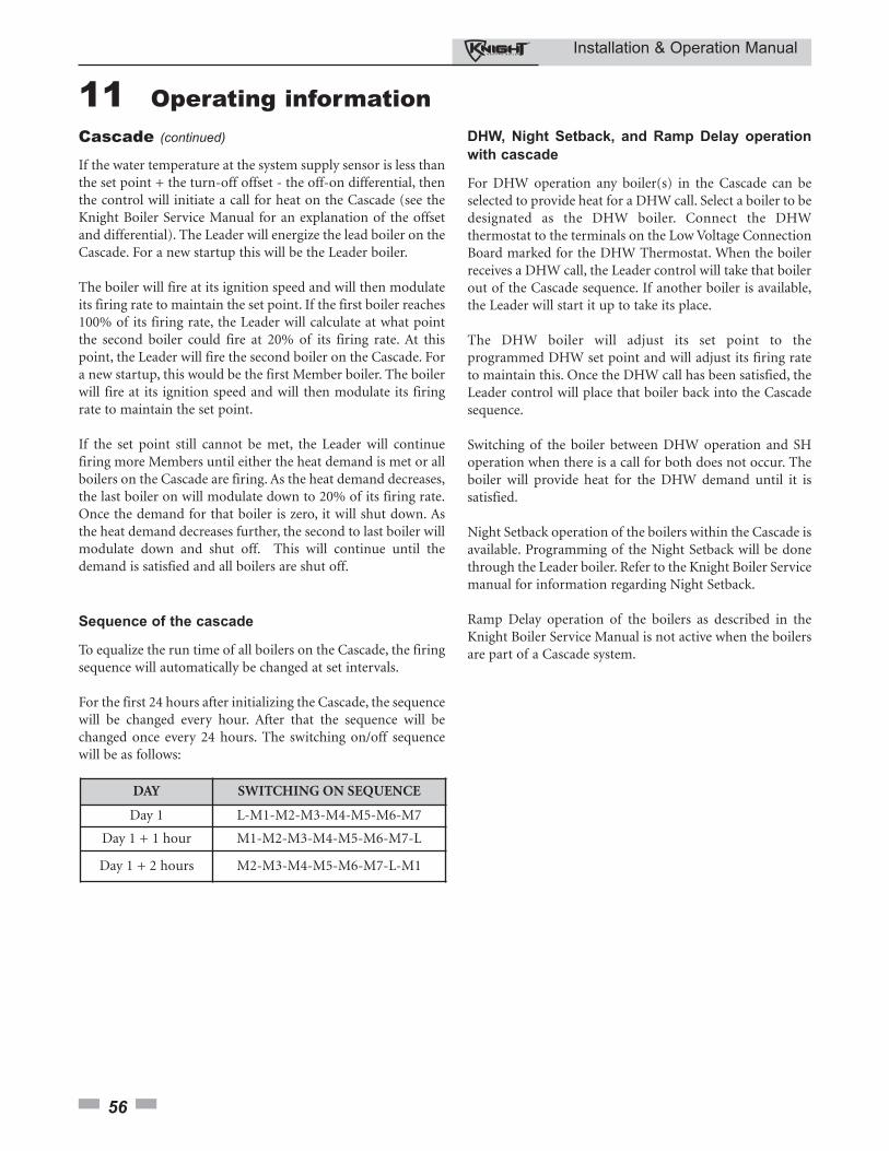
Installation & Operation Manual
56
11 Operating information Cascade (continued)
If the water temperature at the system supply sensor is less thanthe set point + the turn-off offset - the off-on differential, thenthe control will initiate a call for heat on the Cascade (see theKnight Boiler Service Manual for an explanation of the offsetand differential). The Leader will energize the lead boiler on theCascade. For a new startup this will be the Leader boiler.
The boiler will fire at its ignition speed and will then modulateits firing rate to maintain the set point. If the first boiler reaches100% of its firing rate, the Leader will calculate at what pointthe second boiler could fire at 20% of its firing rate. At thispoint, the Leader will fire the second boiler on the Cascade. Fora new startup, this would be the first Member boiler. The boilerwill fire at its ignition speed and will then modulate its firingrate to maintain the set point.
If the set point still cannot be met, the Leader will continuefiring more Members until either the heat demand is met or allboilers on the Cascade are firing. As the heat demand decreases,the last boiler on will modulate down to 20% of its firing rate.Once the demand for that boiler is zero, it will shut down. Asthe heat demand decreases further, the second to last boiler willmodulate down and shut off. This will continue until thedemand is satisfied and all boilers are shut off.
DHW, Night Setback, and Ramp Delay operation
with cascade
For DHW operation any boiler(s) in the Cascade can beselected to provide heat for a DHW call. Select a boiler to bedesignated as the DHW boiler. Connect the DHWthermostat to the terminals on the Low Voltage ConnectionBoard marked for the DHW Thermostat. When the boilerreceives a DHW call, the Leader control will take that boilerout of the Cascade sequence. If another boiler is available,the Leader will start it up to take its place.
The DHW boiler will adjust its set point to theprogrammed DHW set point and will adjust its firing rateto maintain this. Once the DHW call has been satisfied, theLeader control will place that boiler back into the Cascadesequence.
Switching of the boiler between DHW operation and SHoperation when there is a call for both does not occur. Theboiler will provide heat for the DHW demand until it issatisfied.
Night Setback operation of the boilers within the Cascade isavailable. Programming of the Night Setback will be donethrough the Leader boiler. Refer to the Knight Boiler Servicemanual for information regarding Night Setback.
Ramp Delay operation of the boilers as described in theKnight Boiler Service Manual is not active when the boilersare part of a Cascade system.
Sequence of the cascade
To equalize the run time of all boilers on the Cascade, the firingsequence will automatically be changed at set intervals.
For the first 24 hours after initializing the Cascade, the sequencewill be changed every hour. After that the sequence will bechanged once every 24 hours. The switching on/off sequencewill be as follows:
DAY SWITCHING ON SEQUENCE
Day 1 L-M1-M2-M3-M4-M5-M6-M7
Day 1 + 1 hour M1-M2-M3-M4-M5-M6-M7-L
Day 1 + 2 hours M2-M3-M4-M5-M6-M7-L-M1
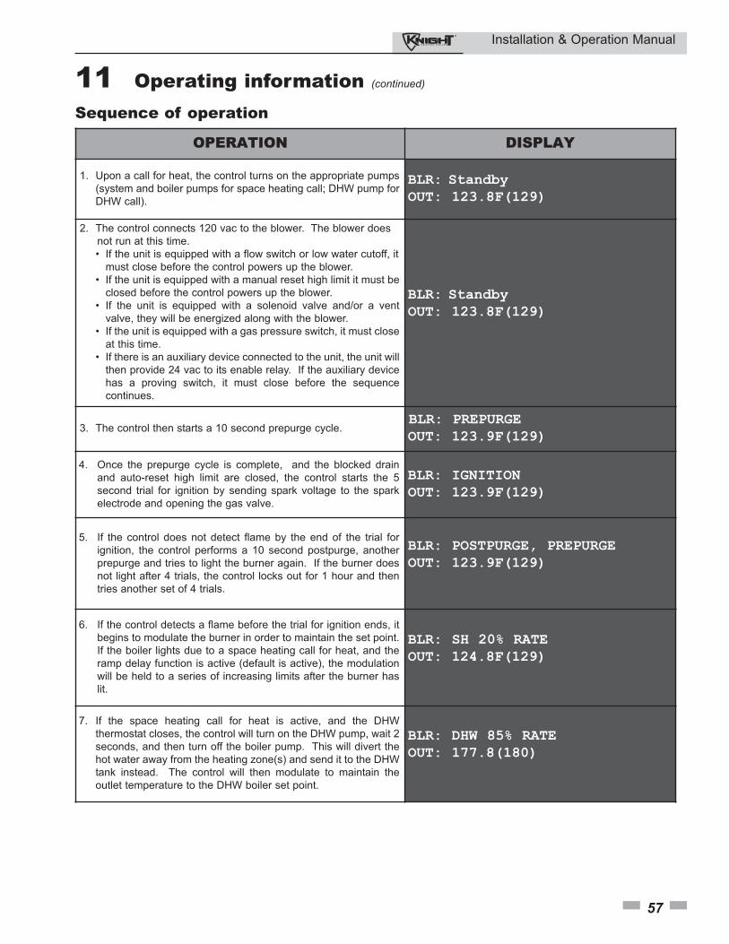
Installation & Operation Manual
57
OPERATION DISPLAY
1. Upon a call for heat, the control turns on the appropriate pumps
(system and boiler pumps for space heating call; DHW pump for
DHW call).
BLR: StandbyOUT: 123.8F(129)
2. The control connects 120 vac to the blower. The blower does
not run at this time.
• If the unit is equipped with a flow switch or low water cutoff, it
must close before the control powers up the blower.
• If the unit is equipped with a manual reset high limit it must be
closed before the control powers up the blower.
• If the unit is equipped with a solenoid valve and/or a vent
valve, they will be energized along with the blower.
• If the unit is equipped with a gas pressure switch, it must close
at this time.
• If there is an auxiliary device connected to the unit, the unit will
then provide 24 vac to its enable relay. If the auxiliary device
has a proving switch, it must close before the sequence
continues.
BLR: StandbyOUT: 123.8F(129)
3. The control then starts a 10 second prepurge cycle. BLR: PREPURGEOUT: 123.9F(129)
4. Once the prepurge cycle is complete, and the blocked drain
and auto-reset high limit are closed, the control starts the 5
second trial for ignition by sending spark voltage to the spark
electrode and opening the gas valve.
BLR: IGNITIONOUT: 123.9F(129)
5. If the control does not detect flame by the end of the trial for
ignition, the control performs a 10 second postpurge, another
prepurge and tries to light the burner again. If the burner does
not light after 4 trials, the control locks out for 1 hour and then
tries another set of 4 trials.
BLR: POSTPURGE, PREPURGEOUT: 123.9F(129)
6. If the control detects a flame before the trial for ignition ends, it
begins to modulate the burner in order to maintain the set point.
If the boiler lights due to a space heating call for heat, and the
ramp delay function is active (default is active), the modulation
will be held to a series of increasing limits after the burner has
lit.
BLR: SH 20% RATEOUT: 124.8F(129)
7. If the space heating call for heat is active, and the DHW
thermostat closes, the control will turn on the DHW pump, wait 2
seconds, and then turn off the boiler pump. This will divert the
hot water away from the heating zone(s) and send it to the DHW
tank instead. The control will then modulate to maintain the
outlet temperature to the DHW boiler set point.
BLR: DHW 85% RATEOUT: 177.8(180)
Sequence of operation
11 Operating information (continued)
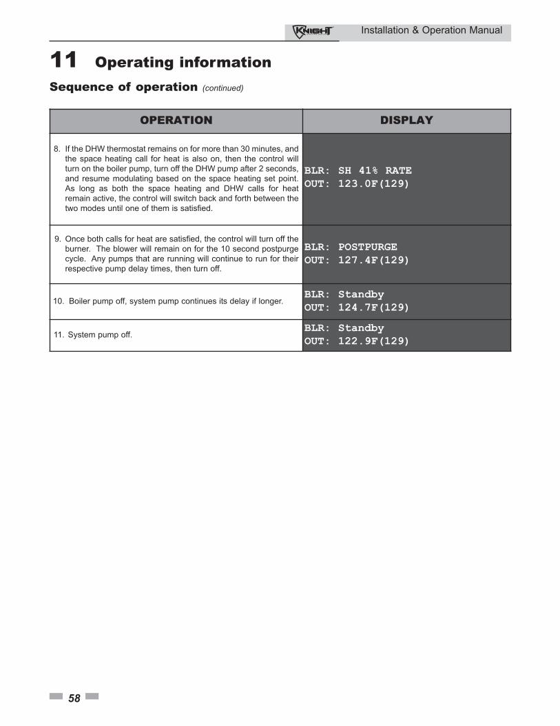
Installation & Operation Manual
58
11 Operating information Sequence of operation (continued)
OPERATION DISPLAY
8. If the DHW thermostat remains on for more than 30 minutes, and
the space heating call for heat is also on, then the control will
turn on the boiler pump, turn off the DHW pump after 2 seconds,
and resume modulating based on the space heating set point.
As long as both the space heating and DHW calls for heat
remain active, the control will switch back and forth between the
two modes until one of them is satisfied.
BLR: SH 41% RATEOUT: 123.0F(129)
9. Once both calls for heat are satisfied, the control will turn off the
burner. The blower will remain on for the 10 second postpurge
cycle. Any pumps that are running will continue to run for their
respective pump delay times, then turn off.
BLR: POSTPURGEOUT: 127.4F(129)
10. Boiler pump off, system pump continues its delay if longer.BLR: StandbyOUT: 124.7F(129)
11. System pump off.BLR: StandbyOUT: 122.9F(129)

Installation & Operation Manual
59
Knight boiler control module
Figure 11-1 Control Panel
Use the control panel (FIG. 11-1) to set temperatures, operating conditions, and monitor boiler operation.
11 Operating information (continued)
Installation & Operation Manual
60
Access modes
User
The user can adjust space heating target temperature by using theUP and DOWN buttons (FIG. 11-1) at any time during normaloperation. By entering the USER code (0704), the user can alsochange temperature units, time and date, and night setbacksettings. In User Mode, the following parameters can be viewedbut not changed:
• Boiler outlet water target temperature in DHW Mode
• Boiler model number• Software version• Total operating hours• Total cycles
Installer
Most parameters are available only to the installer, accessible onlyby entering the installer access code, see the Knight Boiler ServiceManual.
Saving parameters (reference the Parameter Table in theKnight Boiler Service Manual)
To save parameters and exit programming:
Press the ENTER/RESET button.
To keep parameter settings only for a current operating cycle:
Press the MENU/EXIT button 3 times after making all desiredparameter changes.
To enter a parameter and continue programming:
Press the MENU/EXIT button 1 time to return to the parameterlistings; press again to return to the menu listings. Remember topress the ENTER/RESET button when finished programming inorder to save the changes made.
See the Knight Boiler Service Manual for a detailed description ofparameters and access modes.
11 Operating information
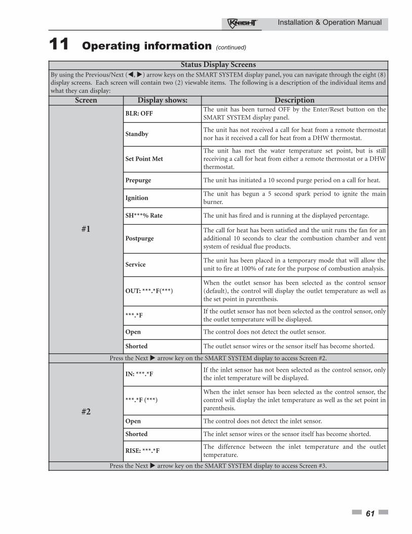
Installation & Operation Manual
61
Status Display ScreensBy using the Previous/Next (�, �) arrow keys on the SMART SYSTEM display panel, you can navigate through the eight (8)display screens. Each screen will contain two (2) viewable items. The following is a description of the individual items andwhat they can display:
Screen Display shows: Description
#1
BLR: OFFThe unit has been turned OFF by the Enter/Reset button on theSMART SYSTEM display panel.
StandbyThe unit has not received a call for heat from a remote thermostatnor has it received a call for heat from a DHW thermostat.
Set Point MetThe unit has met the water temperature set point, but is stillreceiving a call for heat from either a remote thermostat or a DHWthermostat.
Prepurge The unit has initiated a 10 second purge period on a call for heat.
IgnitionThe unit has begun a 5 second spark period to ignite the mainburner.
SH***% Rate The unit has fired and is running at the displayed percentage.
PostpurgeThe call for heat has been satisfied and the unit runs the fan for anadditional 10 seconds to clear the combustion chamber and ventsystem of residual flue products.
ServiceThe unit has been placed in a temporary mode that will allow theunit to fire at 100% of rate for the purpose of combustion analysis.
OUT: ***.*F(***)When the outlet sensor has been selected as the control sensor(default), the control will display the outlet temperature as well asthe set point in parenthesis.
***.*FIf the outlet sensor has not been selected as the control sensor, onlythe outlet temperature will be displayed.
Open The control does not detect the outlet sensor.
Shorted The outlet sensor wires or the sensor itself has become shorted.
Press the Next � arrow key on the SMART SYSTEM display to access Screen #2.
#2
IN: ***.*FIf the inlet sensor has not been selected as the control sensor, onlythe inlet temperature will be displayed.
***.*F (***)When the inlet sensor has been selected as the control sensor, thecontrol will display the inlet temperature as well as the set point inparenthesis.
Open The control does not detect the inlet sensor.
Shorted The inlet sensor wires or the sensor itself has become shorted.
RISE: ***.*FThe difference between the inlet temperature and the outlettemperature.
Press the Next � arrow key on the SMART SYSTEM display to access Screen #3.
11 Operating information (continued)
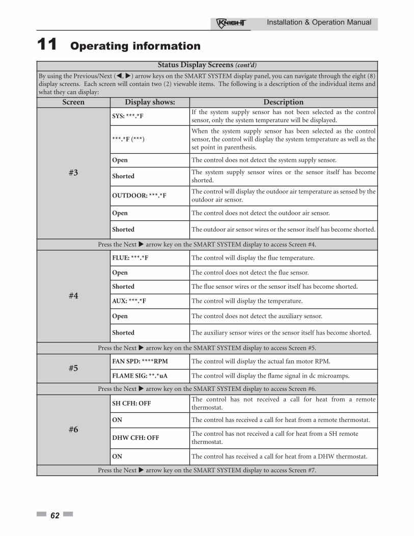
Installation & Operation Manual
62
Status Display Screens (cont’d)
By using the Previous/Next (�, �) arrow keys on the SMART SYSTEM display panel, you can navigate through the eight (8)display screens. Each screen will contain two (2) viewable items. The following is a description of the individual items andwhat they can display:
Screen Display shows: Description
#3
SYS: ***.*FIf the system supply sensor has not been selected as the controlsensor, only the system temperature will be displayed.
***.*F (***)When the system supply sensor has been selected as the controlsensor, the control will display the system temperature as well as theset point in parenthesis.
Open The control does not detect the system supply sensor.
ShortedThe system supply sensor wires or the sensor itself has becomeshorted.
OUTDOOR: ***.*FThe control will display the outdoor air temperature as sensed by theoutdoor air sensor.
Open The control does not detect the outdoor air sensor.
Shorted The outdoor air sensor wires or the sensor itself has become shorted.
Press the Next � arrow key on the SMART SYSTEM display to access Screen #4.
#4
FLUE: ***.*F The control will display the flue temperature.
Open The control does not detect the flue sensor.
Shorted The flue sensor wires or the sensor itself has become shorted.
AUX: ***.*F The control will display the temperature.
Open The control does not detect the auxiliary sensor.
Shorted The auxiliary sensor wires or the sensor itself has become shorted.
Press the Next � arrow key on the SMART SYSTEM display to access Screen #5.
#5FAN SPD: ****RPM The control will display the actual fan motor RPM.
FLAME SIG: **.*uA The control will display the flame signal in dc microamps.
Press the Next � arrow key on the SMART SYSTEM display to access Screen #6.
#6
SH CFH: OFFThe control has not received a call for heat from a remotethermostat.
ON The control has received a call for heat from a remote thermostat.
DHW CFH: OFFThe control has not received a call for heat from a SH remotethermostat.
ON The control has received a call for heat from a DHW thermostat.
Press the Next � arrow key on the SMART SYSTEM display to access Screen #7.
11 Operating information
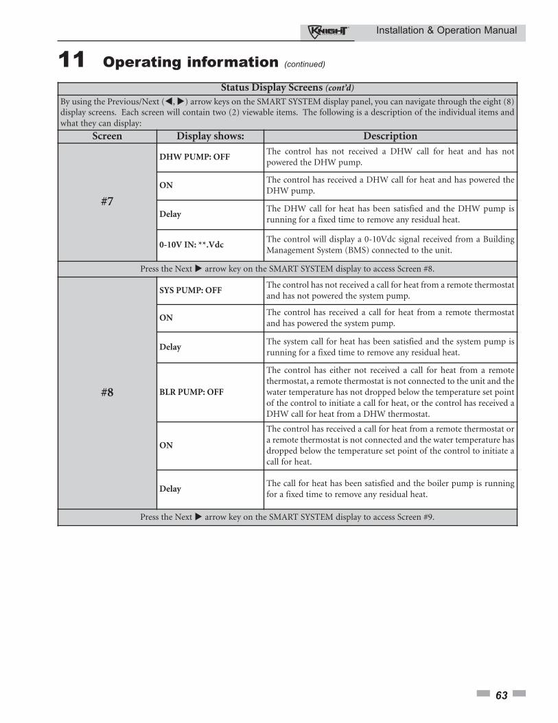
Installation & Operation Manual
63
Status Display Screens (cont’d)
By using the Previous/Next (�, �) arrow keys on the SMART SYSTEM display panel, you can navigate through the eight (8)display screens. Each screen will contain two (2) viewable items. The following is a description of the individual items andwhat they can display:
Screen Display shows: Description
#7
DHW PUMP: OFFThe control has not received a DHW call for heat and has notpowered the DHW pump.
ONThe control has received a DHW call for heat and has powered theDHW pump.
DelayThe DHW call for heat has been satisfied and the DHW pump isrunning for a fixed time to remove any residual heat.
0-10V IN: **.VdcThe control will display a 0-10Vdc signal received from a BuildingManagement System (BMS) connected to the unit.
Press the Next � arrow key on the SMART SYSTEM display to access Screen #8.
#8
SYS PUMP: OFFThe control has not received a call for heat from a remote thermostatand has not powered the system pump.
ONThe control has received a call for heat from a remote thermostatand has powered the system pump.
DelayThe system call for heat has been satisfied and the system pump isrunning for a fixed time to remove any residual heat.
BLR PUMP: OFF
The control has either not received a call for heat from a remotethermostat, a remote thermostat is not connected to the unit and thewater temperature has not dropped below the temperature set pointof the control to initiate a call for heat, or the control has received aDHW call for heat from a DHW thermostat.
ON
The control has received a call for heat from a remote thermostat ora remote thermostat is not connected and the water temperature hasdropped below the temperature set point of the control to initiate acall for heat.
DelayThe call for heat has been satisfied and the boiler pump is runningfor a fixed time to remove any residual heat.
Press the Next � arrow key on the SMART SYSTEM display to access Screen #9.
11 Operating information (continued)
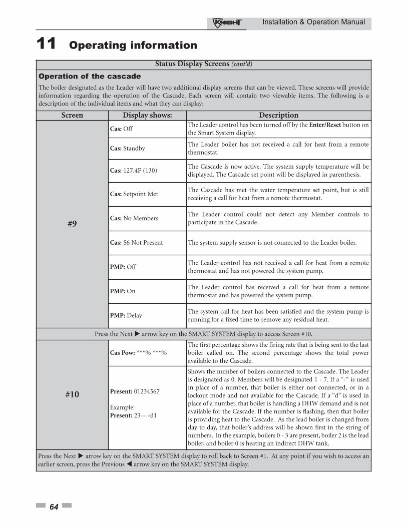
Installation & Operation Manual
64
Status Display Screens (cont’d)
Operation of the cascadeThe boiler designated as the Leader will have two additional display screens that can be viewed. These screens will provideinformation regarding the operation of the Cascade. Each screen will contain two viewable items. The following is adescription of the individual items and what they can display:
Screen Display shows: Description
#9
Cas: OffThe Leader control has been turned off by the Enter/Reset button onthe Smart System display.
Cas: StandbyThe Leader boiler has not received a call for heat from a remotethermostat.
Cas: 127.4F (130)The Cascade is now active. The system supply temperature will bedisplayed. The Cascade set point will be displayed in parenthesis.
Cas: Setpoint MetThe Cascade has met the water temperature set point, but is stillreceiving a call for heat from a remote thermostat.
Cas: No MembersThe Leader control could not detect any Member controls toparticipate in the Cascade.
Cas: S6 Not Present The system supply sensor is not connected to the Leader boiler.
PMP: OffThe Leader control has not received a call for heat from a remotethermostat and has not powered the system pump.
PMP: OnThe Leader control has received a call for heat from a remotethermostat and has powered the system pump.
PMP: DelayThe system call for heat has been satisfied and the system pump isrunning for a fixed time to remove any residual heat.
Press the Next � arrow key on the SMART SYSTEM display to access Screen #10.
#10
Cas Pow: ***% ***%The first percentage shows the firing rate that is being sent to the lastboiler called on. The second percentage shows the total poweravailable to the Cascade.
Present: 01234567
Example:Present: 23----d1
Shows the number of boilers connected to the Cascade. The Leaderis designated as 0. Members will be designated 1 - 7. If a “-“ is usedin place of a number, that boiler is either not connected, or in alockout mode and not available for the Cascade. If a “d” is used inplace of a number, that boiler is handling a DHW demand and is notavailable for the Cascade. If the number is flashing, then that boileris providing heat to the Cascade. As the lead boiler is changed fromday to day, that boiler’s address will be shown first in the string ofnumbers. In the example, boilers 0 - 3 are present, boiler 2 is the leadboiler, and boiler 0 is heating an indirect DHW tank.
Press the Next � arrow key on the SMART SYSTEM display to roll back to Screen #1. At any point if you wish to access anearlier screen, press the Previous � arrow key on the SMART SYSTEM display.
11 Operating information
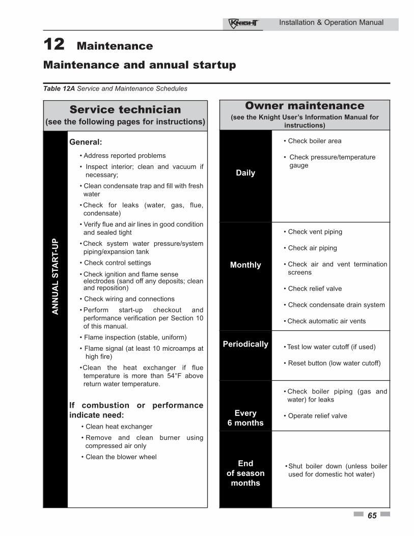
Installation & Operation Manual
12 Maintenance
65
Maintenance and annual startup
Table 12A Service and Maintenance Schedules
Service technician(see the following pages for instructions)
General:
• Address reported problems
• Inspect interior; clean and vacuum if
necessary;
• Clean condensate trap and fill with fresh
water
• Check for leaks (water, gas, flue,
condensate)
• Verify flue and air lines in good condition
and sealed tight
• Check system water pressure/system
piping/expansion tank
• Check control settings
• Check ignition and flame sense electrodes (sand off any deposits; clean and reposition)
• Check wiring and connections
• Perform start-up checkout and
performance verification per Section 10
of this manual.
• Flame inspection (stable, uniform)
• Flame signal (at least 10 microamps at
high fire)
•Clean the heat exchanger if flue
temperature is more than 54°F above
return water temperature.
If combustion or performance
indicate need:
• Clean heat exchanger
• Remove and clean burner using
compressed air only
• Clean the blower wheel
AN
NU
AL
STA
RT-U
P
Owner maintenance(see the Knight User’s Information Manual for
instructions)
Daily
• Check boiler area
• Check pressure/temperature
gauge
Monthly
• Check vent piping
• Check air piping
• Check air and vent termination
screens
• Check relief valve
• Check condensate drain system
• Check automatic air vents
Periodically • Test low water cutoff (if used)
• Reset button (low water cutoff)
Every
6 months
• Check boiler piping (gas and
water) for leaks
• Operate relief valve
End
of season
months
• Shut boiler down (unless boiler
used for domestic hot water)
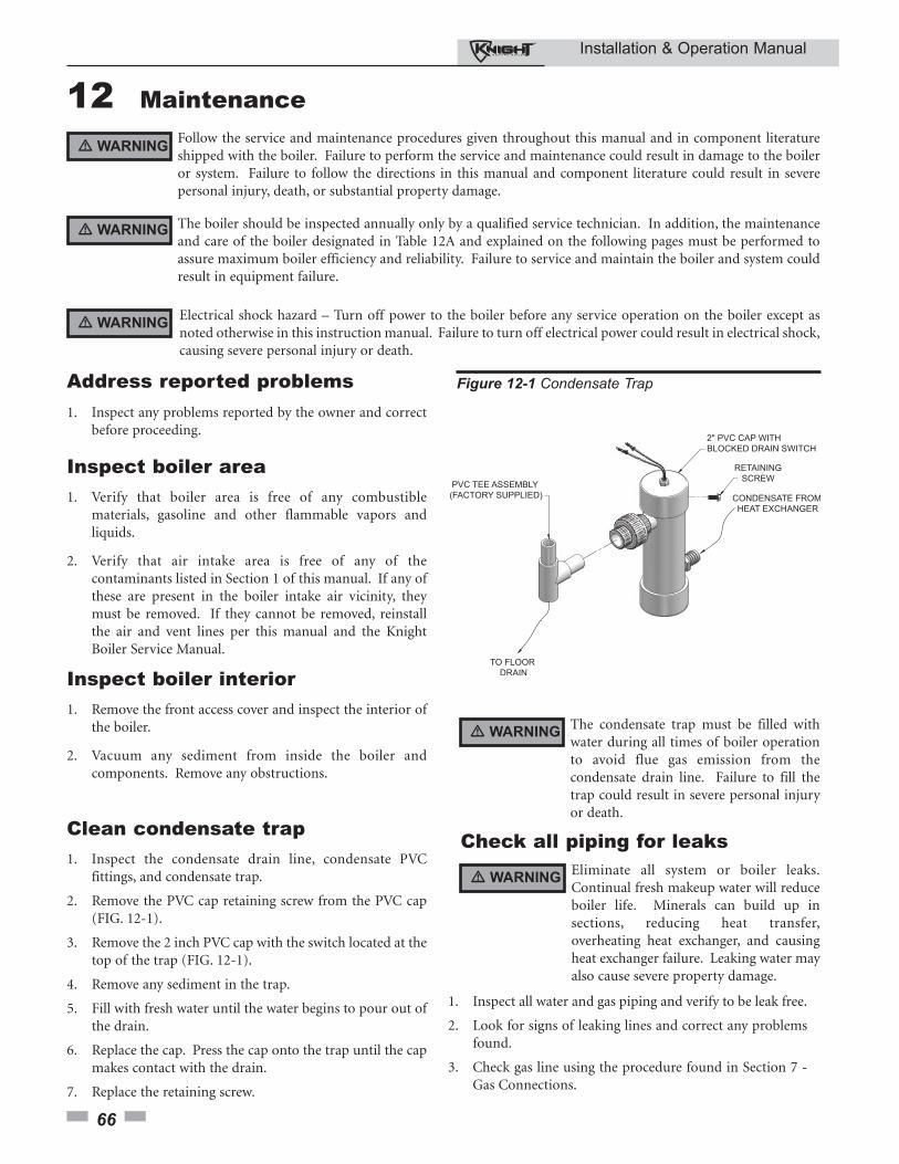
Installation & Operation Manual
12 Maintenance
66
Follow the service and maintenance procedures given throughout this manual and in component literatureshipped with the boiler. Failure to perform the service and maintenance could result in damage to the boileror system. Failure to follow the directions in this manual and component literature could result in severepersonal injury, death, or substantial property damage.
The boiler should be inspected annually only by a qualified service technician. In addition, the maintenanceand care of the boiler designated in Table 12A and explained on the following pages must be performed toassure maximum boiler efficiency and reliability. Failure to service and maintain the boiler and system couldresult in equipment failure.
Electrical shock hazard – Turn off power to the boiler before any service operation on the boiler except asnoted otherwise in this instruction manual. Failure to turn off electrical power could result in electrical shock,causing severe personal injury or death.
Address reported problems1. Inspect any problems reported by the owner and correct
before proceeding.
Inspect boiler area1. Verify that boiler area is free of any combustible
materials, gasoline and other flammable vapors andliquids.
2. Verify that air intake area is free of any of thecontaminants listed in Section 1 of this manual. If any ofthese are present in the boiler intake air vicinity, theymust be removed. If they cannot be removed, reinstallthe air and vent lines per this manual and the KnightBoiler Service Manual.
Inspect boiler interior1. Remove the front access cover and inspect the interior of
the boiler.
2. Vacuum any sediment from inside the boiler andcomponents. Remove any obstructions.
Clean condensate trap1. Inspect the condensate drain line, condensate PVC
fittings, and condensate trap.
2. Remove the PVC cap retaining screw from the PVC cap(FIG. 12-1).
3. Remove the 2 inch PVC cap with the switch located at thetop of the trap (FIG. 12-1).
4. Remove any sediment in the trap.
5. Fill with fresh water until the water begins to pour out ofthe drain.
6. Replace the cap. Press the cap onto the trap until the capmakes contact with the drain.
7. Replace the retaining screw.
Eliminate all system or boiler leaks.Continual fresh makeup water will reduceboiler life. Minerals can build up insections, reducing heat transfer,overheating heat exchanger, and causingheat exchanger failure. Leaking water mayalso cause severe property damage.
1. Inspect all water and gas piping and verify to be leak free.
2. Look for signs of leaking lines and correct any problemsfound.
3. Check gas line using the procedure found in Section 7 -Gas Connections.
Check all piping for leaks
The condensate trap must be filled withwater during all times of boiler operationto avoid flue gas emission from thecondensate drain line. Failure to fill thetrap could result in severe personal injuryor death.
� WARNING
� WARNING
� WARNING
� WARNING
� WARNING
Figure 12-1 Condensate Trap
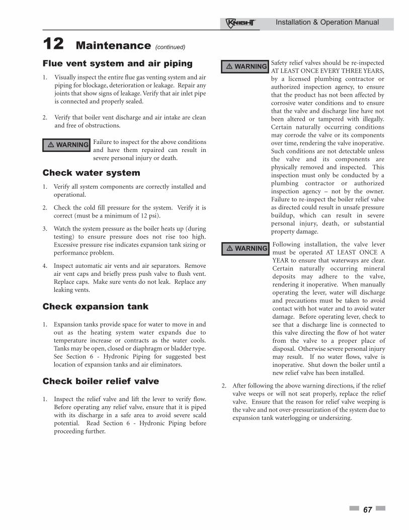
Installation & Operation Manual
67
12 Maintenance (continued)
Flue vent system and air piping1. Visually inspect the entire flue gas venting system and air
piping for blockage, deterioration or leakage. Repair anyjoints that show signs of leakage. Verify that air inlet pipeis connected and properly sealed.
2. Verify that boiler vent discharge and air intake are cleanand free of obstructions.
Failure to inspect for the above conditionsand have them repaired can result insevere personal injury or death.
Check water system1. Verify all system components are correctly installed and
operational.
2. Check the cold fill pressure for the system. Verify it iscorrect (must be a minimum of 12 psi).
3. Watch the system pressure as the boiler heats up (duringtesting) to ensure pressure does not rise too high.Excessive pressure rise indicates expansion tank sizing orperformance problem.
4. Inspect automatic air vents and air separators. Removeair vent caps and briefly press push valve to flush vent.Replace caps. Make sure vents do not leak. Replace anyleaking vents.
Check expansion tank
1. Expansion tanks provide space for water to move in andout as the heating system water expands due totemperature increase or contracts as the water cools.Tanks may be open, closed or diaphragm or bladder type.See Section 6 - Hydronic Piping for suggested bestlocation of expansion tanks and air eliminators.
Check boiler relief valve
1. Inspect the relief valve and lift the lever to verify flow.Before operating any relief valve, ensure that it is pipedwith its discharge in a safe area to avoid severe scaldpotential. Read Section 6 - Hydronic Piping beforeproceeding further.
Safety relief valves should be re-inspectedAT LEAST ONCE EVERY THREE YEARS,by a licensed plumbing contractor orauthorized inspection agency, to ensurethat the product has not been affected bycorrosive water conditions and to ensurethat the valve and discharge line have notbeen altered or tampered with illegally.Certain naturally occurring conditionsmay corrode the valve or its componentsover time, rendering the valve inoperative.Such conditions are not detectable unlessthe valve and its components arephysically removed and inspected. Thisinspection must only be conducted by aplumbing contractor or authorizedinspection agency – not by the owner.Failure to re-inspect the boiler relief valveas directed could result in unsafe pressurebuildup, which can result in severepersonal injury, death, or substantialproperty damage.
Following installation, the valve levermust be operated AT LEAST ONCE AYEAR to ensure that waterways are clear.Certain naturally occurring mineraldeposits may adhere to the valve,rendering it inoperative. When manuallyoperating the lever, water will dischargeand precautions must be taken to avoidcontact with hot water and to avoid waterdamage. Before operating lever, check tosee that a discharge line is connected tothis valve directing the flow of hot waterfrom the valve to a proper place ofdisposal. Otherwise severe personal injurymay result. If no water flows, valve isinoperative. Shut down the boiler until anew relief valve has been installed.
2. After following the above warning directions, if the reliefvalve weeps or will not seat properly, replace the reliefvalve. Ensure that the reason for relief valve weeping isthe valve and not over-pressurization of the system due toexpansion tank waterlogging or undersizing.
� WARNING
� WARNING
� WARNING
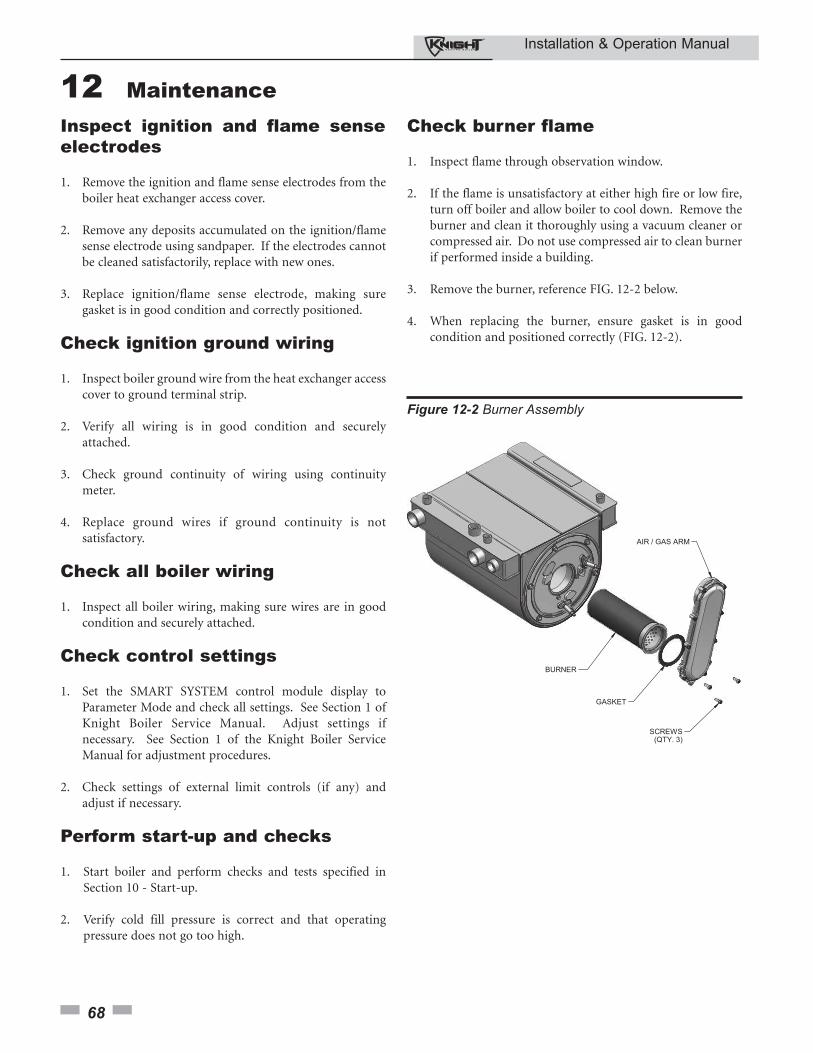
Installation & Operation Manual
12 Maintenance
68
Inspect ignition and flame senseelectrodes
1. Remove the ignition and flame sense electrodes from theboiler heat exchanger access cover.
2. Remove any deposits accumulated on the ignition/flamesense electrode using sandpaper. If the electrodes cannotbe cleaned satisfactorily, replace with new ones.
3. Replace ignition/flame sense electrode, making suregasket is in good condition and correctly positioned.
Check ignition ground wiring
1. Inspect boiler ground wire from the heat exchanger accesscover to ground terminal strip.
2. Verify all wiring is in good condition and securelyattached.
3. Check ground continuity of wiring using continuitymeter.
4. Replace ground wires if ground continuity is notsatisfactory.
Check all boiler wiring
1. Inspect all boiler wiring, making sure wires are in goodcondition and securely attached.
Check control settings
1. Set the SMART SYSTEM control module display toParameter Mode and check all settings. See Section 1 ofKnight Boiler Service Manual. Adjust settings ifnecessary. See Section 1 of the Knight Boiler ServiceManual for adjustment procedures.
2. Check settings of external limit controls (if any) andadjust if necessary.
Perform start-up and checks
1. Start boiler and perform checks and tests specified inSection 10 - Start-up.
2. Verify cold fill pressure is correct and that operatingpressure does not go too high.
Check burner flame
1. Inspect flame through observation window.
2. If the flame is unsatisfactory at either high fire or low fire,turn off boiler and allow boiler to cool down. Remove theburner and clean it thoroughly using a vacuum cleaner orcompressed air. Do not use compressed air to clean burnerif performed inside a building.
3. Remove the burner, reference FIG. 12-2 below.
4. When replacing the burner, ensure gasket is in goodcondition and positioned correctly (FIG. 12-2).
Figure 12-2 Burner Assembly
Installation & Operation Manual
69
Check flame signal
1. At high fire the flame signal shown on the display shouldbe at least 10 microamps.
2. A lower flame signal may indicate a fouled or damagedflame sense electrode. If cleaning the flame senseelectrode does not improve, ground wiring is in goodcondition, and ground continuity is satisfactory, replacethe flame sense electrode.
3. See Section 3 - Troubleshooting of the Knight BoilerService Manual for other procedures to deal with lowflame signal.
Review with owner
1. Review the Knight Boiler User’s Information Manualwith the owner.
2. Emphasize the need to perform the maintenanceschedule specified in the Knight Boiler User’sInformation Manual (and in this manual as well).
3. Remind the owner of the need to call a licensedcontractor should the boiler or system exhibit anyunusual behavior.
4. Remind the owner to follow the proper shutdownprocedure and to schedule an annual start-up at thebeginning of the next heating season.
Cleaning boiler heat exchanger
1. Shut down boiler:• Follow the “To Turn Off Gas to Appliance” instructions
for the boiler in Section 10 - Startup.• Do not drain the boiler unless it will be exposed to
freezing temperatures. If using freeze prevention fluid in system, do not drain.
2. Allow time for the boiler to cool to room temperature ifit has been firing.
3. Remove the blower assembly (gas air/arm) from the heatexchanger access cover. Set bolts aside.
4. Remove the nuts securing the heat exchanger access coverto the heat exchanger and set aside.
5. Remove the heat exchanger access cover, cover gasket(s)and chamber insulation assembly.
The boiler contains ceramic fibermaterials. Use care when handling thesematerials per instructions in the KnightBoiler Service Manual. Failure to complycould result in severe personal injury.
6. Use a vacuum cleaner to remove any accumulation on theboiler heating surfaces. Do not use any solvent.
7. Finish cleaning using a clean cloth dampened with warmwater.
8. Install access cover gasket, chamber insulation assemblyand cover.
9. Secure nuts on the studs. DO NOT overtighten.
10. Re-install the blower assembly (gas air/arm) using thebolts set aside in Step 3.
11. Close isolation valves on piping to isolate boiler fromsystem. Attach a hose to the boiler drain and flush boilerthoroughly with clean water by using purging valves toallow water to flow through the water make-up line to theboiler.
12. When the boiler has been flushed, restore boiler tooperation.
13. Perform start-up and check-out procedures in Section 10- Startup.
Oiled bearing circulators
1. The circulator shipped with the Knight boiler is water-lubricated. No oiling is required.
2. Check other circulators in the system. Oil any circulatorsrequiring oil, following circulator manufacturer’sinstructions. Over-oiling will damage the circulator.
3. Replace the boiler front access cover.
� WARNING
12 Maintenance (continued)
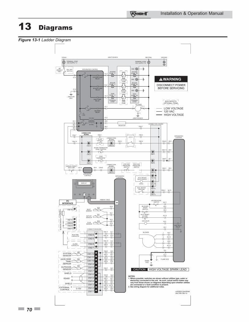
Installation & Operation Manual
70
13 Diagrams
BOX DEPICTSOPTIONAL ITEMS
LADDER DIAGRAMLBL7083 REV G
120 VAC
24 VAC
120VAC
TERMINAL STRIP120V SUPPLY "L"
ON / OFFSWITCH
X1-6
BOILER PUMPRELAY
DHW PUMPRELAY
SYSTEM PUMPRELAY
BLOWERRELAY
X1-4
X1-3
X1-2
X1-1
BOILERPUMP "L"
DHWPUMP "L"
SYSTEMPUMP "L"
BOILERPUMP
DHWPUMP
SYSTEMPUMP
BOILERPUMP "N"
DHWPUMP "N"
SYSTEMPUMP "N"
1 2
3
BLOWER
JUNCTION BOXX1-5
X6-8
X6-3
F5
X5-7
X6-7
NEUTRAL
CN4-1
CONNECTION BOARDCN4-7 CN5-1
TERMINAL STRIP120V SUPPLY "N"
JUNCTIONBOX
X1-8
FLOWSWITCH
CONNECTION BOARD
CN5-3
LWCOCN5-2
CN5-4
ROOM THERMOSTATZONE CONTROL
DHWTHERMOSTAT
CONNECTION BOARD
CONNECTION BOARD
CN4-6
CN4-13
CN4-5
CN4-3
X6-9
X6-6
X6-1
X6-5
INTEGRATEDCONTROL
MANUAL RESETHIGH LIMIT X5-14 CN4-9X6-4
CONNECTIONBOARD
LOW GASPRESSURE
SWITCH
HIGH GASPRESSURE
SWITCH
AUX. DEVICEPILOT SUPPLY
24VAC
AUX. DEVICEPROVING CN4-2 X6-10
BLOCKEDDRAIN
SWITCH
AUTO RESETHI-LIMIT
X5-11
X5-3
X5-10
X5-4
X2-1
GAS VALVE
GAS VALVERELAY
X5-5
X5-13
X5-6
X5-12
1
2
4
5
5A
F4
3.5A
F2
3.5A
F31.25A
TR1
X1-7
FLAME RODSPARK
ROD
INTEGRATED CONTROL
GROUNDJUNCTION BOX
INTEGRATEDCONTROL
120 VACLOW VOLTAGE
HIGH VOLTAGE
CAUTION HIGH VOLTAGE SPARK LEAD
BLOWER
TERMINALSTRIP
TERMINALSTRIP
CN3-8
CN3-7
CN3-9
CN3-6
CN3-4
CN3-3
CN3-1
CN3-10
DISPLAY
CONNECTION BOARD
INLETSENSOR
OUTLETSENSOR
FLUESENSOR
X4-8
X4-7
X4-9
X4-6
X4-4
X4-3
X4-1
X4-10
INTEGRATEDCONTROL
CN4-11
CN4-12
CN4-10
CN4-4ALARMCONTACTS
RUN-TIMECONTACTS
X3-1
X3-3
X3-4
X3-2
X5-8
X5-1
X5-2
X5-9
X3
RIBBON CABLE
CN3-5 X4-5
X8
SYSTEMSENSOR
(AUX) DHWTANK
SENSOR
OUTDOORSENSOR
0-10V+-
RS485A
B
SHIELD
SHIELD
EXTERNALCONTROL
CN1-1
CN3-2 X4-2
CN1-2
CN1-3
CN1-4
CN1-5
CN1-6
CN1-7
CN1-8
CN1-9
CN1-10
CN1-11
CN1-12
CN2-8
CN2-7
CN2-6
CN2-5
PCINTERFACE
CN2-7
CN2-8
CN2-9
CN2-10
CN2-15
SILE
NCIN
G SW
ITCH
ALAR
M B
ELL
S6
S4
S5
S2
S1
S3
CN2-9
CN2-2
CN2-10
CN2-12
CN2-1
CN2-3
CN2-11
CN2-16
CN2-15
CN2-14
CN2-13
CN2-4
X2-2
GND
GND
GND
X6-2
CN4-14
NOTES:1. Where possible, switches are shown without utilities (gas, water or electricity) connected to the unit. As such, actual switch states may vary from those shown on diagrams depending upon whether utilities are connected or a fault condition is present.2. See wiring diagram for additional notes.
KBMODELSONLY
AIR PRESSURE SWITCH
RESISTOR
Figure 13-1 Ladder Diagram
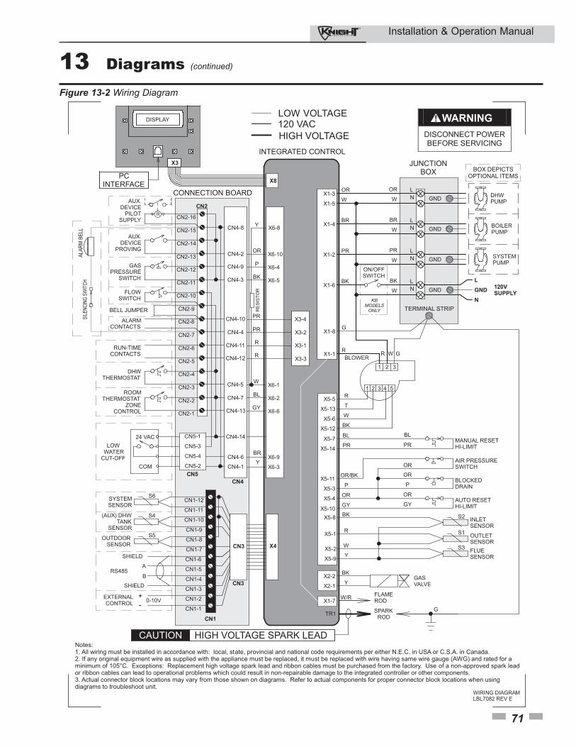
Installation & Operation Manual
71
DISPLAY
X1-8
X5-5
X5-13
X5-6
X5-12
INTEGRATED CONTROL
BLOWERX1-1
X2-2
X2-1
X1-7
GASVALVE
FLAMEROD
SPARKROD
W/R
G
R
R
T
W
BK
GR
1 32
W
G
BOX DEPICTSOPTIONAL ITEMS
WIRING DIAGRAMLBL7082 REV E
WARNING
DISCONNECT POWER BEFORE SERVICING
INLETSENSOR
OUTLETSENSORFLUESENSOR
MANUAL RESETHI-LIMIT
BLOCKEDDRAIN
X5-8
X5-1
X5-2
X5-9
X5-7
X5-14
X5-11
X5-3
X5-4
X5-10BK
R
W
Y
BL
PR
OR/BK
P
OR
GY
BL
PR
OR
P
OR
GY
1 2 4 53
SYSTEMSENSOR
(AUX) DHW TANK
SENSOR
OUTDOORSENSOR
0-10V+-
RS485A
B
CONNECTION BOARD
CN3 X4
X1-3
X1-5
X1-2
X1-6
X1-4
120VSUPPLY
BOILERPUMP
DHWPUMP
SYSTEMPUMP
JUNCTIONBOX
TERMINAL STRIP
OR
W
PR
BK
BR
OR
W
PR
BK
BR
W
W
W
L N
ON/OFFSWITCH
L
GND
N
SHIELD
SHIELD
BK
Y
FLOWSWITCH
GASPRESSURE
SWITCH
AUX. DEVICE
PROVING
LOW WATERCUT-OFF
CN5-1
CN4-6
CN4-1
CN4-9
CN4-3
CN4-2
X6-9
X6-3
X6-4
X6-5
X6-10
BR
Y
P
BK
OR
CN4-11
CN4-12
CN4-10
CN4-4
ALARMCONTACTS
RUN-TIMECONTACTS
X3-1
X3-3
X3-4
X3-2
R
R
PR
PR
AUX.DEVICE
PILOTSUPPLY
CN4-8 X6-8Y
DHWTHERMOSTAT
CN4-5 X6-1W
ROOMTHERMOSTAT
ZONECONTROL
CN4-7
CN4-13
X6-2
X6-6
BL
GY
R
EXTERNALCONTROL
AUTO RESETHI-LIMIT
CAUTION HIGH VOLTAGE SPARK LEAD
CN5-3
CN5-4
CN5-2
24 VAC
COM
L N
L N
L N
GND
GND
GND
GND
TR1
X8
120 VACLOW VOLTAGE
HIGH VOLTAGE
X3
PCINTERFACE
CN4-14
CN1-12
CN1-11
CN1-10
CN1-9
CN1-8
CN1-7
CN1-6
CN1-5
CN1-4
CN1-3
CN1-2
CN1-1
Notes:1. All wiring must be installed in accordance with: local, state, provincial and national code requirements per either N.E.C. in USA or C.S.A. in Canada.2. If any original equipment wire as supplied with the appliance must be replaced, it must be replaced with wire having same wire gauge (AWG) and rated for aminimum of 105°C. Exceptions: Replacement high voltage spark lead and ribbon cables must be purchased from the factory. Use of a non-approved spark leador ribbon cables can lead to operational problems which could result in non-repairable damage to the integrated controller or other components.3. Actual connector block locations may vary from those shown on diagrams. Refer to actual components for proper connector block locations when usingdiagrams to troubleshoot unit.
CN2-1
CN2-2
CN2-3
CN2-4
CN2-5
CN2-6
CN2-7
CN2-8
CN2-9
CN2-10
CN2-11
CN2-12
CN2-13
CN2-14
CN2-15
CN2-16
CN1
CN2
CN5
CN4
CN3
BELL JUMPER
ALAR
M B
ELL
SILE
NCIN
G SW
ITCH
S6
S4
S5
S2
S1
S3
KBMODELSONLY
AIR PRESSURESWITCHOR
RE
SIS
TOR
Figure 13-2 Wiring Diagram
13 Diagrams (continued)
Revision Notes: Revision 7 (KB-I&O-07) reflectsthe addition of the Dungs information to the manual.
Revision 8 (KB-I&O-08) reflects edits made to all theplumbing diagrams.
Revision 9 (KB-I&O-09) reflects changes made tothe ratings page.
Revision 10 (KB-I&O-10) reflects changes made toModel 210 orifice.
Revision 11 (KB-I&O-11) reflects an additional LPwarning on page 13.
Revision 12 (ECO #C02407) reflects the removal ofModels 399 - 500 from the manual, the addition ofhigh altitude, relief valve and T & P installinstructions, Maintenance Section and the newsidewall vent termination.
Revision 13 (ECO #C02545) reflects the addition ofreferences to the safety shutoff testing andinstructions, sediment trap, periodic cleaning ofscreens in vent terminations, wall thickness for directvent terminations, removal of B149.2 references,approval of the 3" concentric vent kit for ULC-S636and sidewall vent termination kit number correction.
KB-I&O-1311/08