installation & operation manual - sponsler pickup coil furnished with each sponsler precision...
TRANSCRIPT

INSTALLATION & OPERATION MANUAL
Precision Turbine Flowmeters
TABLE OF CONTENTS
PAGE #
DESCRIPTION
1
Forward
2
Pre-Installation Inspection, Installation
3
Installation (continued)
4
3 Typical Meter Runs
5
Typical Flowstraightener Section
6
FIGURE 1: 1/4” Assembly Procedure
7
FIGURE 2: 1/2” and Larger Assembly Procedure
8
FIGURE 3: MF20-90 Assembly Procedure
9
FIGURE 4: MF100-175 Assembly Procedure
10
11
FIGURE 5: Corrosive Meter Assembly Procedure FIGURE 6: 3A Sanitary Meter Assembly Procedure
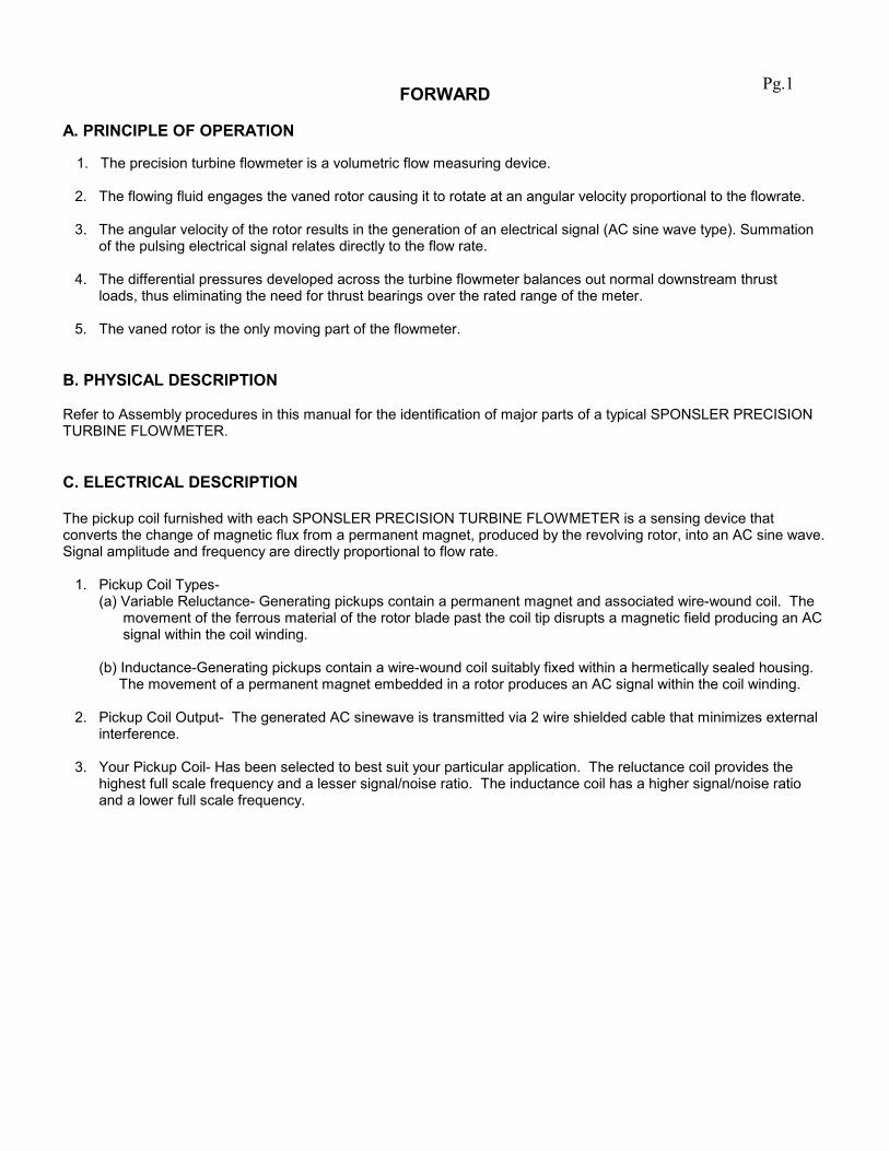
FORWARD
A. PRINCIPLE OF OPERATION 1. The precision turbine flowmeter is a volumetric flow measuring device. 2. The flowing fluid engages the vaned rotor causing it to rotate at an angular velocity proportional to the flowrate. 3. The angular velocity of the rotor results in the generation of an electrical signal (AC sine wave type). Summation of the pulsing electrical signal relates directly to the flow rate. 4. The differential pressures developed across the turbine flowmeter balances out normal downstream thrust loads, thus eliminating the need for thrust bearings over the rated range of the meter. 5. The vaned rotor is the only moving part of the flowmeter. B. PHYSICAL DESCRIPTION Refer to Assembly procedures in this manual for the identification of major parts of a typical SPONSLER PRECISION TURBINE FLOWMETER. C. ELECTRICAL DESCRIPTION The pickup coil furnished with each SPONSLER PRECISION TURBINE FLOWMETER is a sensing device that converts the change of magnetic flux from a permanent magnet, produced by the revolving rotor, into an AC sine wave. Signal amplitude and frequency are directly proportional to flow rate. 1. Pickup Coil Types- (a) Variable Reluctance- Generating pickups contain a permanent magnet and associated wire-wound coil. The movement of the ferrous material of the rotor blade past the coil tip disrupts a magnetic field producing an AC signal within the coil winding. (b) Inductance-Generating pickups contain a wire-wound coil suitably fixed within a hermetically sealed housing. The movement of a permanent magnet embedded in a rotor produces an AC signal within the coil winding. 2. Pickup Coil Output- The generated AC sinewave is transmitted via 2 wire shielded cable that minimizes external interference. 3. Your Pickup Coil- Has been selected to best suit your particular application. The reluctance coil provides the highest full scale frequency and a lesser signal/noise ratio. The inductance coil has a higher signal/noise ratio and a lower full scale frequency.
Pg.1
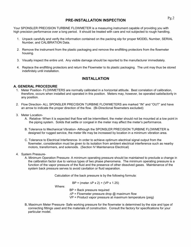
PRE-INSTALLATION INSPECTION
Your SPONSLER PRECISION TURBINE FLOWMETER is a measuring instrument capable of providing you with high precision performance over a long period. It should be treated with care and not subjected to rough handling. 1. Unpack carefully and verify the information contained on the packing slip for proper MODEL Number, SERIAL Number, and CALIBRATION Data. 2. Remove the instrument from the plastic packaging and remove the endfitting protectors from the flowmeter housing. 3. Visually inspect the entire unit. Any visible damage should be reported to the manufacturer immediately. 4. Replace the endfitting protectors and return the Flowmeter to its plastic packaging. The unit may thus be stored indefinitely until installation.
INSTALLATION
A. GENERAL PROCEDURE 1. Meter Position- FLOWMETERS are normally calibrated in a horizontal attitude. Best correlation of calibration, therefore, occurs when installed and operated in this position. Meters may, however, be operated satisfactorily in any position. 2. Flow Direction- ALL SPONSLER PRECISION TURBINE FLOWMETERS are marked “IN” and “OUT” and have an arrow to indicate the proper direction of the flow. (Bi-Directional flowmeters excluded) 3. Meter Location- A. Relative- When it is expected that flow will be intermittent, the meter should not be mounted at a low point in the piping system. Solids that settle or congeal in the meter may affect the meter’s performance. B. Tolerance to Mechanical Vibration- Although the SPONSLER PRECISION TURBINE FLOWMETER is designed for rugged service, the meter life may be increased by location in a minimum vibration area. C. Tolerance to Electrical Interference- In order to achieve optimum electrical signal output from the flowmeter, consideration must be given to its isolation from ambient electrical interference such as nearby motors, transformers, and solenoids. (Section IV Maintenance Electrical) 4. System Pressure- A. Minimum Operation Pressure- A minimum operating pressure should be maintained to preclude a change in the calibration factor due to various types of two phase phenomena. The minimum operating pressure is a function of the vapor pressure of the fluid and the presence of other dissolved gases. Maintenance of the system back pressure serves to avoid cavitation or fluid separation.
Calculation of the back pressure is by the following formula:
BP = (meter ∆P x 2) + (VP x 1.25) Where: BP = Back pressure required ∆P = Flowmeter pressure drop @ maximum flow VP = Product vapor pressure at maximum temperature (psig) B. Maximum Meter Pressure- Safe working pressure for the flowmeter is determined by the size and type of connecting fittings used and the materials of construction. Consult the factory for specifications for your particular model.
Pg.2

B. PIPING 1. General Piping Considerations- As explained in the FORWARD, the fluid moving through the flowmeter engages the angled blades of the turbine rotor. Thus the rotational velocity of the rotor is a function of the fluid velocity and the blade angle engagement. Swirl present in the fluid ahead of the meter can change the effective angle of engagement and, therefore, cause a deviation from the supplied calibration (done under controlled flow conditions). Proper installation of the Flowmeter minimizes the harmful effects of fluid swirl. 2. The Meter Location- That section of the pipe immediately preceding, including, and following the flowmeter is known as “THE METERING LOCATION”. Three typical metering arrangements are described in the following section of this manual. Each is designed to minimize fluid swirl. A flowstraightener is also shown and should be used where installation does not allow the otherwise straight run of pipe upstream of the meter. PLEASE NOTE: The required lengths of pipe are given in pipe diameters and represent the minimum distances between piping components that are recommended to eliminate flow disturbances. 3. Meter-By-Pass- Where possible, such as in a new piping system, it is advisable to include a valved by-pass around the flowmeter. However, the by-pass connections are not to be placed within the recommended metering run. 4. Line Purge- In a newly installed piping system or one in which fittings have been disturbed, the line should be flushed thoroughly prior to installing the instrument to minimize possible damage to the flowmeter from foreign materials. C. ELECTRICAL CONNECTION The standard SPONSLER PRECISION TURBINE FLOWMETER pickup coil is designed to mate with an MS310610SL-4S connector. A two-wire shielded cable should be used to lead from the connector to the electronic instrument in use. The cable shield is connected (grounded) to the appropriate connector on the display unit ONLY, in order to minimize ground-loop and interface difficulties. The connection cable should be located away from power lines whenever possible. Precautions should be taken when removing or installing the pickup coil. Any physical damage such as bent threads or twisted leads are not covered by SPONSLER CO., INC warranty. D. ASSEMBLY NOTES 1. Removal of internals should be performed in a clean area. 2. Ensure that internals are clean and dry before reassembling.
Pg.3
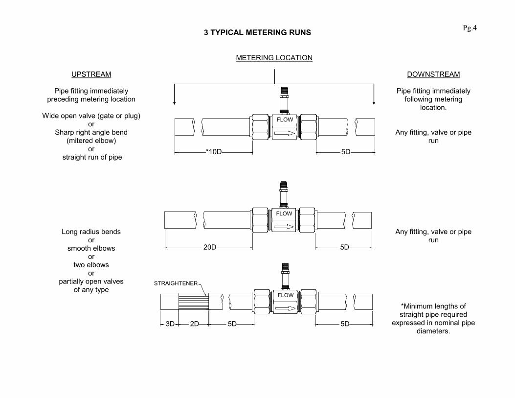
3 TYPICAL METERING RUNS
UPSTREAM
Pipe fitting immediately preceding metering location
Wide open valve (gate or plug)
or Sharp right angle bend
(mitered elbow) or
straight run of pipe
METERING LOCATION
DOWNSTREAM
Pipe fitting immediately following metering
location.
Any fitting, valve or pipe run
Long radius bends or
smooth elbows or
two elbows or
partially open valves of any type
Any fitting, valve or pipe run
*Minimum lengths of straight pipe required
expressed in nominal pipe diameters.
5D*10D
FLOW
5D5D2D3D
STRAIGHTENER
FLOW
20D
FLOW
5D
Pg.4
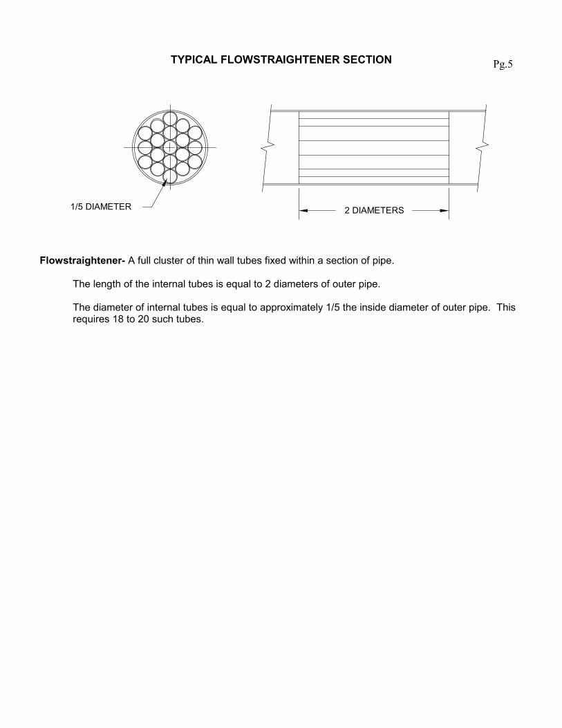
TYPICAL FLOWSTRAIGHTENER SECTION
1/5 DIAMETER 2 DIAMETERS
Flowstraightener- A full cluster of thin wall tubes fixed within a section of pipe. The length of the internal tubes is equal to 2 diameters of outer pipe. The diameter of internal tubes is equal to approximately 1/5 the inside diameter of outer pipe. This requires 18 to 20 such tubes.
Pg.5
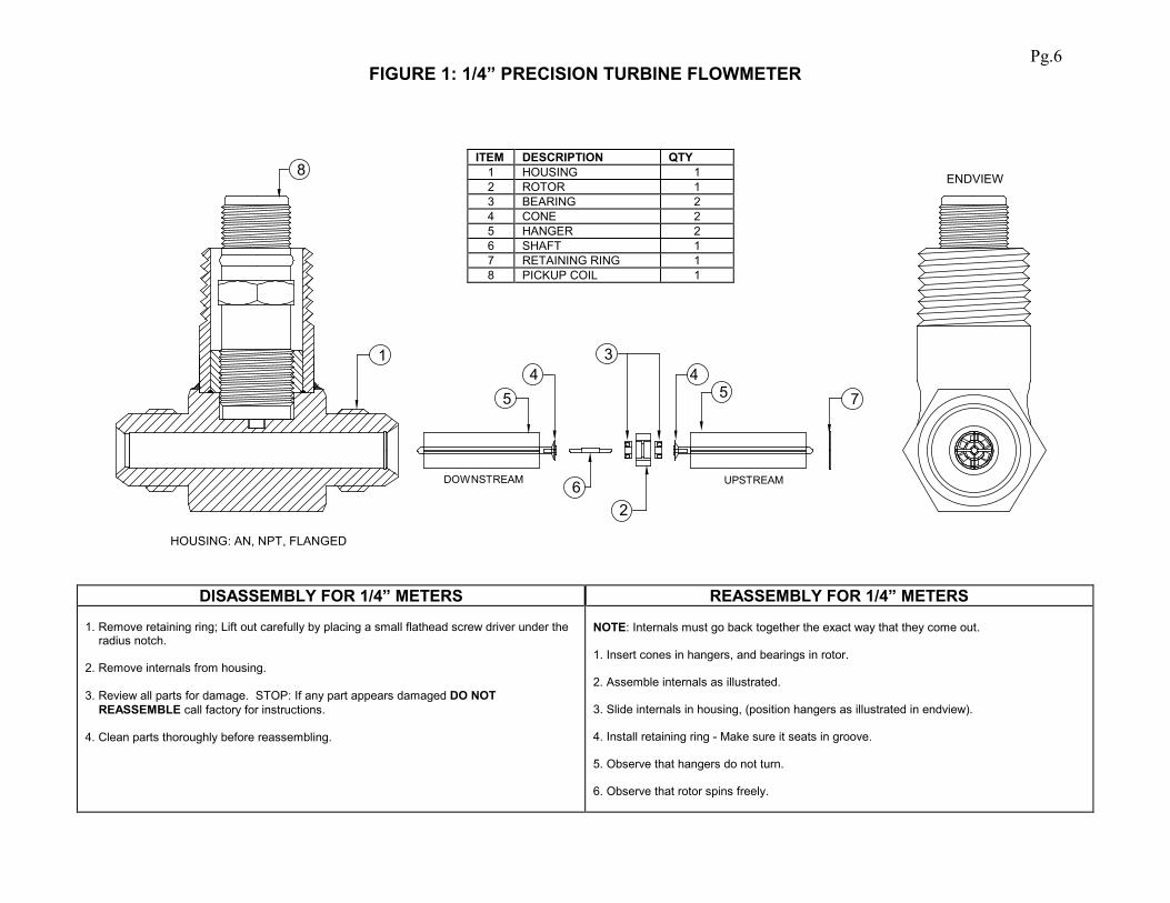
FIGURE 1: 1/4” PRECISION TURBINE FLOWMETER
HOUSING: AN, NPT, FLANGED
5
3
2
1
6DOWNSTREAM UPSTREAM
8
5 74
ENDVIEW
4
DISASSEMBLY FOR 1/4” METERS REASSEMBLY FOR 1/4” METERS
1. Remove retaining ring; Lift out carefully by placing a small flathead screw driver under the radius notch. 2. Remove internals from housing. 3. Review all parts for damage. STOP: If any part appears damaged DO NOT REASSEMBLE call factory for instructions. 4. Clean parts thoroughly before reassembling.
NOTE: Internals must go back together the exact way that they come out. 1. Insert cones in hangers, and bearings in rotor. 2. Assemble internals as illustrated. 3. Slide internals in housing, (position hangers as illustrated in endview). 4. Install retaining ring - Make sure it seats in groove. 5. Observe that hangers do not turn. 6. Observe that rotor spins freely.
ITEM DESCRIPTION QTY 1 HOUSING 1 2 ROTOR 1 3 BEARING 2 4 CONE 2 5 HANGER 2 6 SHAFT 1 7 RETAINING RING 1 8 PICKUP COIL 1
Pg.6

FIGURE 2: 1/2” & LARGER PRECISION TURBINE FLOWMETER
F
HOUSING: AN, NPT, FLANGE (AN shown)
A
B CD
E
END VIEW
1A1B1C
FIT TO ROTORDO NOT REMOVE
2 CARBIDE ONLY FIT TO SHAFT DO NOT REMOVE
PICKUP COIL
LC
DISASSEMBLY FOR 1/2” AND LARGER METERS REASSEMBLY FOR 1/2” AND LARGER METERS FOR BALL BEARING FOR SLEEVED BEARING FOR BALL BEARING FOR SLEEVED BEARING
1. Remove lock nut from shaft end marked “IN”. 2. Insert extraction hook into “IN” clip assembly and extract with a parallel pulling motion. 3. Remove cone, bearings and rotor. 4. Remove “OUT” clip assembly with extraction hook as directed in step 2. DO NOT remove lock nut. Leave clip, cone, shaft and nut assembled. (Refer to diagram)
Before beginning: Assembly must go back together the exact way it comes out. 1. Remove lock nut from shaft end marked “IN”. 2. Insert extraction hook into “IN” clip assembly and extract with a parallel pulling motion. 3. Remove cone and rotor. DO NOT attempt to remove bearing from rotor. 4. Remove “OUT” clip assembly with extraction hook as directed in step 2. DO NOT remove lock nut. Leave clip, cone, shaft and nut assembled. (Refer to diagram)
NOTE: If any part appears damaged “DO NOT REASSEMBLE”. Call factory for instructions 1. Place meter on table vertically, “OUT” side upward. 2. Insert “OUT” clip/cone/shaft/nut assembly into housing as illustrated in endview diagram, push down as far as it will go (seating against step in housing) Clip bundle diameter may need to be clamped for easier insertion. 3. Flip meter around and insert bearing, rotor, bearing , then cone. Be sure the “IN” marking on the rotor coincides with the “IN” marking on the housing. 4. Insert “IN” clip assembly. 5. Screw on lock nut snug against “IN” clip assembly. DO NOT OVER TIGHTEN.
NOTE: If any part appears damaged DO NOT REASSEMBLE. Call factory for instructions 1. Place meter on table vertically, “OUT” side upward. 2. Insert “OUT” clip/cone/shaft/nut assembly into housing as illustrated in endview diagram, push down as far as it will go (seating against step in housing) Clip bundle diameter may need to be clamped for easier insertion. 3. Flip meter around and insert rotor with bearing , then cone. Be sure the “IN” marking on the rotor coincides with the “IN” marking on the housing. 4. Insert “IN” clip assembly. 5. Screw on lock nut snug against “IN” clip assembly. DO NOT OVER TIGHTEN.
ITEM DESCRIPTION QTY ITEM DESCRIPTION QTY A BEARING 2 1A CARBIDE SLV. 1 B ROTOR 1 1B TEFLON SLV. 1 C CONE 2 1C GRAPHITAR SLV 1 D CLIP ASSY. 2 2 CARBIDE JRNL 1 E LOCK NUT 2 F SHAFT 1
Pg.7
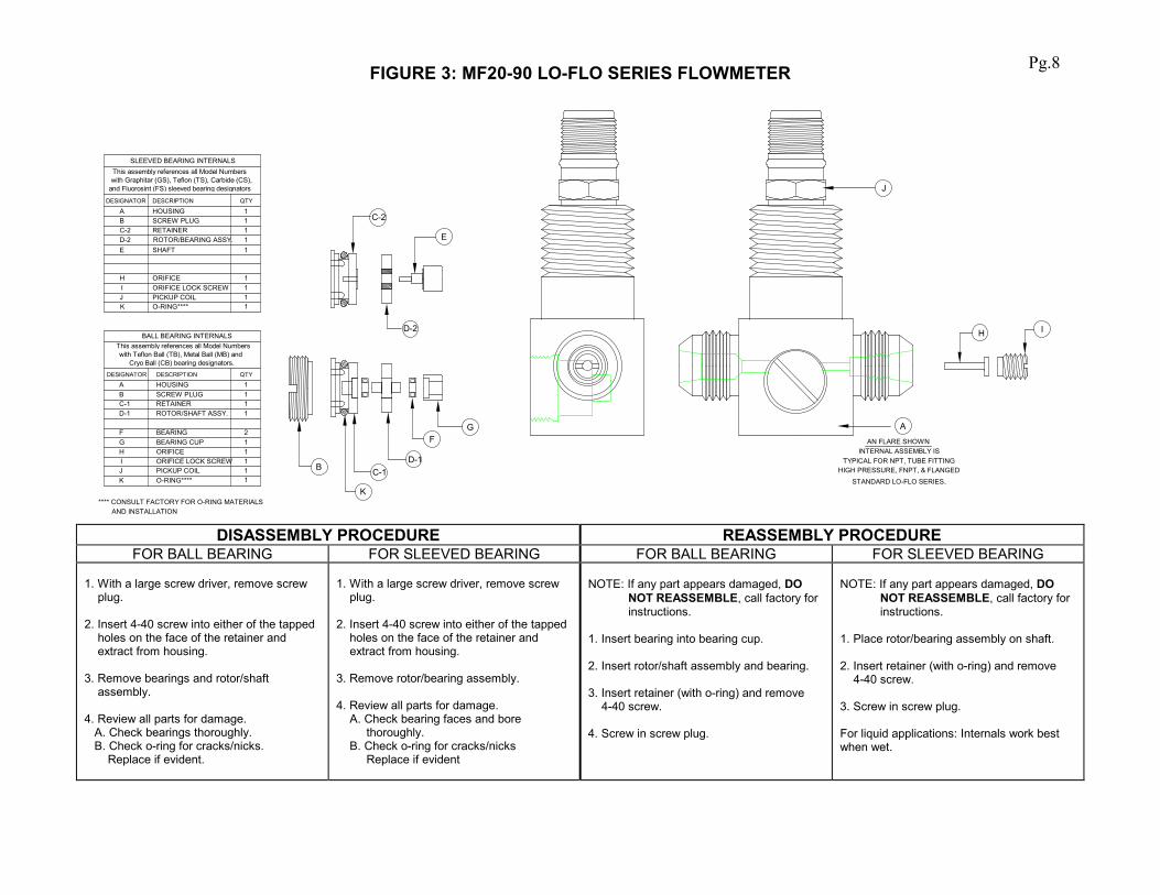
FIGURE 3: MF20-90 LO-FLO SERIES FLOWMETER
GF
D-1C-1
K
B
C-2
D-2
E
H I
J
A
AN FLARE SHOWNINTERNAL ASSEMBLY IS
TYPICAL FOR NPT, TUBE FITTINGHIGH PRESSURE, FNPT, & FLANGED
STANDARD LO-FLO SERIES.
SLEEVED BEARING INTERNALS
111
11111
PICKUP COILORIFICE LOCK SCREWORIFICE
SHAFT
RETAINERSCREW PLUGHOUSING
JIH
E
BA
QTYDESCRIPTIONDESIGNATOR
ROTOR/BEARING ASSY.D-2C-2
K O-RING**** 1
**** CONSULT FACTORY FOR O-RING MATERIALS AND INSTALLATION
1O-RING****K
C-1D-1 ROTOR/SHAFT ASSY.
11112
1111
BALL BEARING INTERNALS
PICKUP COILORIFICE LOCK SCREWORIFICEBEARING CUPBEARING
RETAINERSCREW PLUGHOUSING
JIHGF
BA
QTYDESCRIPTIONDESIGNATOR
This assembly references all Model Numberswith Graphitar (GS), Teflon (TS), Carbide (CS),
This assembly references all Model Numberswith Teflon Ball (TB), Metal Ball (MB) and
and Fluorosint (FS) sleeved bearing designators
Cryo Ball (CB) bearing designators.
DISASSEMBLY PROCEDURE REASSEMBLY PROCEDURE
FOR BALL BEARING FOR SLEEVED BEARING FOR BALL BEARING FOR SLEEVED BEARING 1. With a large screw driver, remove screw plug. 2. Insert 4-40 screw into either of the tapped holes on the face of the retainer and extract from housing. 3. Remove bearings and rotor/shaft assembly. 4. Review all parts for damage. A. Check bearings thoroughly. B. Check o-ring for cracks/nicks. Replace if evident.
1. With a large screw driver, remove screw plug. 2. Insert 4-40 screw into either of the tapped holes on the face of the retainer and extract from housing. 3. Remove rotor/bearing assembly. 4. Review all parts for damage. A. Check bearing faces and bore thoroughly. B. Check o-ring for cracks/nicks Replace if evident
NOTE: If any part appears damaged, DO NOT REASSEMBLE, call factory for instructions. 1. Insert bearing into bearing cup. 2. Insert rotor/shaft assembly and bearing. 3. Insert retainer (with o-ring) and remove 4-40 screw. 4. Screw in screw plug.
NOTE: If any part appears damaged, DO NOT REASSEMBLE, call factory for instructions. 1. Place rotor/bearing assembly on shaft. 2. Insert retainer (with o-ring) and remove 4-40 screw. 3. Screw in screw plug. For liquid applications: Internals work best when wet.
Pg.8
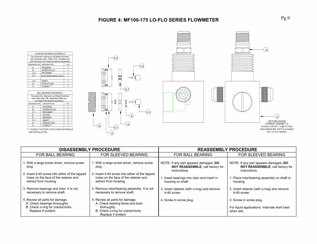
FIGURE 4: MF100-175 LO-FLO SERIES FLOWMETER
SLEEVED BEARING INTERNALS
11
1111
PICKUP COIL
RETAINERSCREW PLUGHOUSING
H
BA
QTYDESCRIPTIONDESIGNATOR
ROTOR/BEARING ASSY.C-2
O-RING****
AAN FLARE SHOWN
D-1
C-1B
C-2
E
D-1
SHAFT 1GF-2
H
D
F-1
F-2
G
**** CONSULT FACTORY FOR O-RING MATERIALS AND INSTALLATION.
F-1
C-1
SHAFTED
O-RING****11
121111
BALL BEARING INTERNALS
PICKUP COIL
BEARINGROTORRETAINERSCREW PLUGHOUSING
HG
BA
QTYDESCRIPTIONDESIGNATOR
This assembly references all Model Numbers
This assembly reference's all Model Numberswith Teflon Ball (TB), Metal Ball (MB) and
with Graphitar (GS), Teflon (TS), Carbide (CS)and Fluorosint (FS) sleeved bearing designator.
Cryo Ball (CB) bearing designator.
INTERNAL ASSEMBLY ISTYPICAL FOR NPT, TUBE FITTING,
HIGH PRESSURE, FNPT & FLANGEDSTD. LO-FLO SERIES.
DISASSEMBLY PROCEDURE REASSEMBLY PROCEDURE FOR BALL BEARING FOR SLEEVED BEARING FOR BALL BEARING FOR SLEEVED BEARING
1. With a large screw driver, remove screw plug. 2. Insert 4-40 screw into either of the tapped holes on the face of the retainer and extract from housing. 3. Remove bearings and rotor. It is not necessary to remove shaft. 4. Review all parts for damage. A. Check bearings thoroughly. B. Check o-ring for cracks/nicks. Replace if evident.
1. With a large screw driver, remove screw plug. 2. Insert 4-40 screw into either of the tapped holes on the face of the retainer and extract from housing. 3. Remove rotor/bearing assembly. It is not necessary to remove shaft. 4. Review all parts for damage. A. Check bearing faces and bore thoroughly. B. Check o-ring for cracks/nicks Replace if evident
NOTE: If any part appears damaged, DO NOT REASSEMBLE, call factory for instructions. 1. Insert bearings into rotor and insert in housing on shaft. 3. Insert retainer (with o-ring) and remove 4-40 screw. 4. Screw in screw plug.
NOTE: If any part appears damaged, DO NOT REASSEMBLE, call factory for instructions. 1. Place rotor/bearing assembly on shaft in housing. 2. Insert retainer (with o-ring) and remove 4-40 screw. 3. Screw in screw plug. For liquid applications: Internals work best when wet.
Pg.9
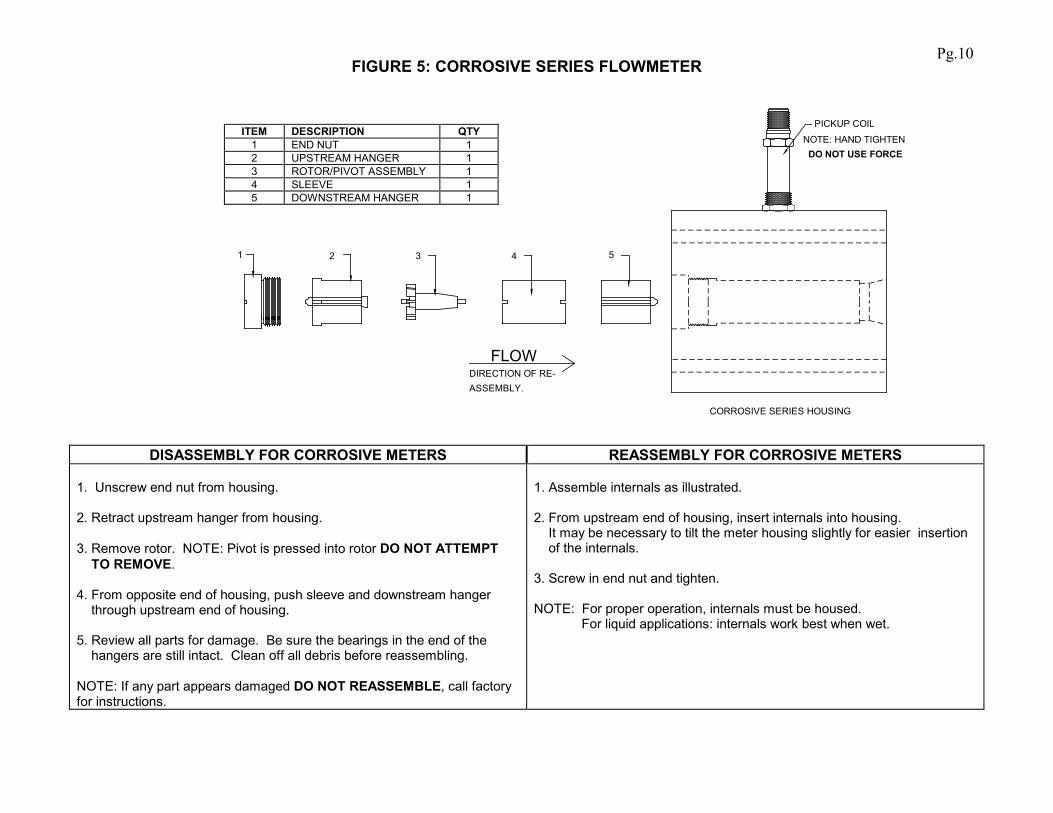
FIGURE 5: CORROSIVE SERIES FLOWMETER
CORROSIVE SERIES HOUSING
ASSEMBLY.DIRECTION OF RE-
54321
PICKUP COIL
NOTE: HAND TIGHTEN DO NOT USE FORCE
FLOW
DISASSEMBLY FOR CORROSIVE METERS REASSEMBLY FOR CORROSIVE METERS 1. Unscrew end nut from housing. 2. Retract upstream hanger from housing. 3. Remove rotor. NOTE: Pivot is pressed into rotor DO NOT ATTEMPT TO REMOVE. 4. From opposite end of housing, push sleeve and downstream hanger through upstream end of housing. 5. Review all parts for damage. Be sure the bearings in the end of the hangers are still intact. Clean off all debris before reassembling. NOTE: If any part appears damaged DO NOT REASSEMBLE, call factory for instructions.
1. Assemble internals as illustrated. 2. From upstream end of housing, insert internals into housing. It may be necessary to tilt the meter housing slightly for easier insertion of the internals. 3. Screw in end nut and tighten. NOTE: For proper operation, internals must be housed. For liquid applications: internals work best when wet.
ITEM DESCRIPTION QTY 1 END NUT 1 2 UPSTREAM HANGER 1 3 ROTOR/PIVOT ASSEMBLY 1 4 SLEEVE 1 5 DOWNSTREAM HANGER 1
Pg.10
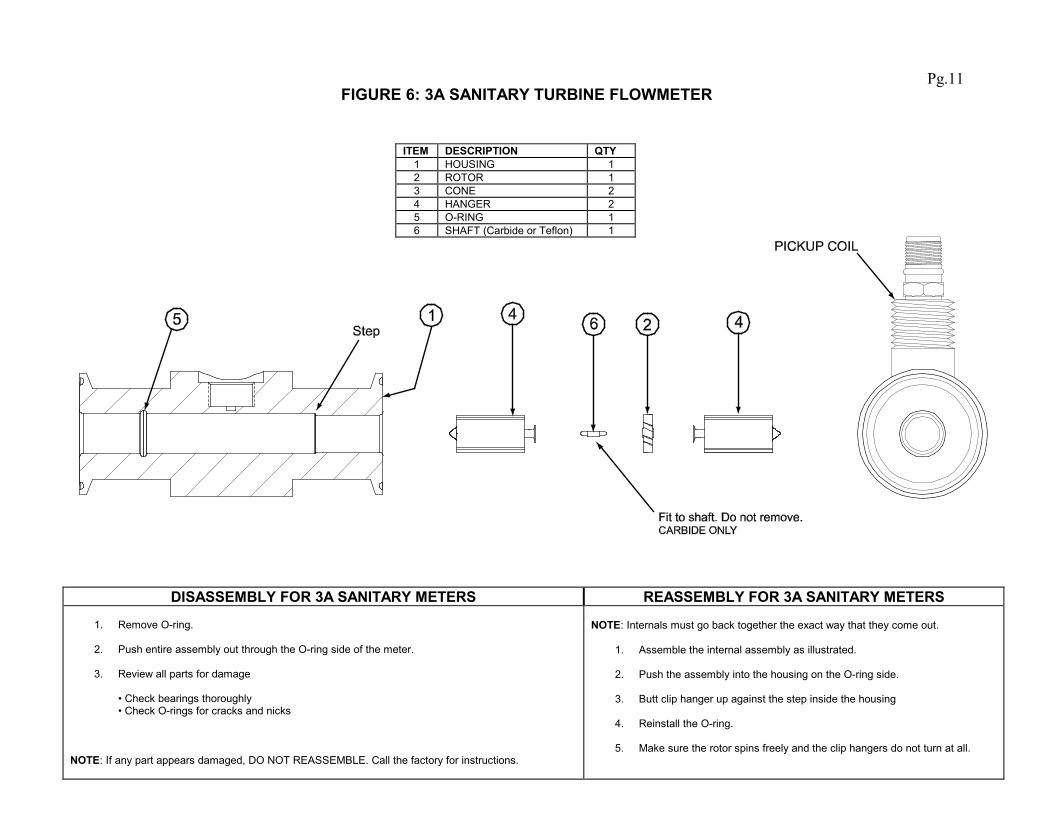
FIGURE 6: 3A SANITARY TURBINE FLOWMETER
DISASSEMBLY FOR 3A SANITARY METERS REASSEMBLY FOR 3A SANITARY METERS
1. Remove O-ring.
2. Push entire assembly out through the O-ring side of the meter.
3. Review all parts for damage • Check bearings thoroughly • Check O-rings for cracks and nicks
NOTE: If any part appears damaged, DO NOT REASSEMBLE. Call the factory for instructions.
NOTE: Internals must go back together the exact way that they come out.
1. Assemble the internal assembly as illustrated.
2. Push the assembly into the housing on the O-ring side.
3. Butt clip hanger up against the step inside the housing
4. Reinstall the O-ring.
5. Make sure the rotor spins freely and the clip hangers do not turn at all.
ITEM DESCRIPTION QTY 1 HOUSING 1 2 ROTOR 1 3 CONE 2 4 HANGER 2 5 O-RING 1 6 SHAFT (Carbide or Teflon) 1
Pg.11


© 2009
Pub. No. MN-PTF-IOMr1 (6/2010)