installation & operation manualmanuals.jacksonmsc.com/ecolab manuals/apex_tsc rev c.pdf ·...
TRANSCRIPT

INSTALLATION & OPERATION MANUAL
FOR ECOLAB MODELS:
APEX TSCAPEX TSC-V
www.ecolab.com
CHEMICAL SANITIZING UPRIGHT DOOR DISHMACHINE
October 15, 2007P/N 7610-003-13-00 (Revision C)
Manufactured in the United States by:


REVISION/PAGE
REVISIONDATE
MADEBY
APPLICABLEECN DETAILS
A 11-07-05 MAW 7576 Release to market test production.
B 07-02-07 MAW 7910 Release to production.
Pgs. 50, 63 & 64 07-25-07 MAW Process Updated schematic to revision C. Changed part number for door
switch.
63 & 70 08-07-07 MAW Process Updated schematic.
C 10-15-07 MAW Process Updated fuse chart. Updated detergent screen number. Updatedschematic.
i
ii
NOMENCLATURE FOR THE MODELS COVERED IN THIS MANUAL
Model:
Serial No.:
Installation Date:
Service Rep. Name:
Phone No.:
APEX TSC-V
APEX TSC- Chemical sanitizing, upright door dishmachineV - Vapor Vent Option
TABLE OF CONTENTS
iii
SECTION DESCRIPTION PAGE
I. SPECIFICATION INFORMATIONSpecifications for Apex TSC 2Specifications for Apex TSC-V 3Dimensions 4
II. INSTALLATION & OPERATION INSTRUCTIONSInstallation Instructions 6Electrical Installation Instructions 7Operation Instructions 8Programming Instructions 14Programming Flow Chart
III. PREVENTATIVE MAINTENANCEPreventative Maintenance 20
IV. TROUBLESHOOTING SECTIONTroubleshooting Guide 22Common Problems 24
V. SERVICE PROCEDURESRinse Solenoid Valve Repair Parts Kit 29Vacuum Breaker Repair Parts Kit 33
VI. PARTS SECTIONStandard Parts 36Chemical Feeder Pump Assembly 39Solenoid Valve Assembly 40Vacuum Breaker Assembly 41Upper Control Box Assembly 42Lower Control Box Assembly 44Detergent/Rinse Aid Dispenser Assembly 45Tablet Dispenser Assembly 48Rinse Aid Dispenser Assembly 49Hood Assembly 50Induction Tube Assembly 51Tub & Associated Components 52Rack Rail Assembly/Frame & Accumulator Weldments 53Motor & Pump Assembly 54Cantilever Arm/Door Assemblies 56Incoming Plumbing Assembly 58Wash Arm/Manifold Assemblies 59Vapor Vent Option Assembly 60False Panel Assembly 61
VII. ELECTRICAL SCHEMATICS120 Volt, 50-60 Hertz, Single Phase 63

1
SECTION 1:SPECIFICATION INFORMATION

APEX TSC Installation & Operation Manual 7610-003-13-00Issued: 07-02-2007 Revised: N/A
SECTION 1: SPECIFICATION INFORMATIONSPECIFICATIONS for APEX TSC
2
PERFORMANCE/CAPABILITIES
OPERATING CAPACITY (RACKS/HOUR)
RACKS PER HOUR (NSF RATED) 46
DISHES PER HOUR 1150
GLASSES PER HOUR 1150
OPERATING CYCLE (SECONDS)
LIGHT CYCLE
WASH TIME 42
RINSE TIME 15
TOTAL CYCLE TIME 72
NORMAL CYCLE
WASH TIME 48
RINSE TIME 25
TOTAL CYCLE TIME 90
HEAVY CYCLE
WASH TIME 118
RINSE TIME 15
TOTAL CYCLE TIME 150
SUPER HEAVY CYCLE
WASH TIME 208
RINSE TIME 15
TOTAL CYCLE TIME 240
TANK CAPACITY (GALLONS)
WASH TANK (MINIMUM) 1.2
WASH PUMP CAPACITY
GALLONS PER MINUTE 61
TEMPERATURES
WASH---°F (MINIMUM) 120
WASH---°F (RECOMMENDED) 140
RINSE---°F (MINIMUM) 120
RINSE---°F (RECOMMENDED) 140
ELECTRICAL REQUIREMENTS
WASH PUMP MOTOR HORSEPOWER 3/4
NOTE: Typical Electrical Circuit is based upon (1) 125% of thefull amperage load of the machine and (2) typical fixed-trip cir-cuit breaker sizes as listed in the NEC 2002 Edition. Localcodes may require more stringent protection than what is dis-played here. Always verify with your electrical service con-tractor that your circuit protection is adequate and meets allapplicable national and local codes. These numbers are pro-vided in this manual simply for reference and may changewithout notice at any given time.
TYPICALTOTAL ELECTRICAL
VOLTS PH HZ AMPS CIRCUIT115 1 60 9 15 AMP
WATER REQUIREMENTS
INLET TEMPERATURE (Minimum) 120°F
INLET TEMPERATURE (Recommended) 140°F
WATER LINE SIZE I.P.S. (Minimum) 1/2”
DRAIN LINE SIZE I.P.S. (Minimum) 2”
FLOW PRESSURE P.S.I. 20±5
MINIMUM CHLORINE REQUIRED (PPM) 50
FRAME DIMENSIONS
WIDTH 25 1/4”
DEPTH 25 1/4”
HEIGHT 66 1/4”
STANDARD TABLE HEIGHT 34”
MAXIMUM CLEARANCE 17”
NOTE: Always refer to the machine data plate for specificelectrical and water requirements. The material provided onthis page is for reference only and may be subject to changewithout notice.

APEX TSC Installation & Operation Manual 7610-003-13-00Issued: 07-02-2007 Revised: N/A
SECTION 1: SPECIFICATION INFORMATIONSPECIFICATIONS for APEX TSC-V
3
PERFORMANCE/CAPABILITIES
OPERATING CAPACITY (RACKS/HOUR)
RACKS PER HOUR (NSF RATED) 34
DISHES PER HOUR 850
GLASSES PER HOUR 850
OPERATING CYCLE (SECONDS) (*Total time extended by30 seconds for vent option)
LIGHT CYCLE
WASH TIME 42
RINSE TIME 15
TOTAL CYCLE TIME 102
NORMAL CYCLE
WASH TIME 48
RINSE TIME 25
TOTAL CYCLE TIME 120
HEAVY CYCLE
WASH TIME 118
RINSE TIME 15
TOTAL CYCLE TIME 180
SUPER HEAVY CYCLE
WASH TIME 208
RINSE TIME 15
TOTAL CYCLE TIME 270
TANK CAPACITY (GALLONS)
WASH TANK (MINIMUM) 1.2
WASH PUMP CAPACITY
GALLONS PER MINUTE 61
TEMPERATURES
WASH---°F (MINIMUM) 120
WASH---°F (RECOMMENDED) 140
RINSE---°F (MINIMUM) 120
RINSE---°F (RECOMMENDED) 140
ELECTRICAL REQUIREMENTS
WASH PUMP MOTOR HORSEPOWER 3/4
NOTE: Typical Electrical Circuit is based upon (1) 125% ofthe full amperage load of the machine and (2) typicalfixed-trip circuit breaker sizes as listed in the NEC 2002Edition. Local codes may require more stringent protec-tion than what is displayed here. Always verify with yourelectrical service contractor that your circuit protection isadequate and meets all applicable national and localcodes. These numbers are provided in this manual sim-ply for reference and may change without notice at anygiven time.
TYPICALTOTAL ELECTRICAL
VOLTS PH HZ AMPS CIRCUIT115 1 60 9 15 AMP
WATER REQUIREMENTS
INLET TEMPERATURE (Minimum) 120°F
INLET TEMPERATURE (Recommended) 140°F
WATER LINE SIZE I.P.S. (Minimum) 1/2”
DRAIN LINE SIZE I.P.S. (Minimum) 2”
FLOW PRESSURE P.S.I. 20±5
MINIMUM CHLORINE REQUIRED (PPM) 50
FRAME DIMENSIONS
WIDTH 25 1/4”
DEPTH 25 1/4”
HEIGHT 66 1/4”
STANDARD TABLE HEIGHT 34”
MAXIMUM CLEARANCE 17”
NOTE: Always refer to the machine data plate for specificelectrical and water requirements. The material providedon this page is for reference only and may be subject tochange without notice.

APEX TSC Installation & Operation Manual 7610-003-13-00Issued: 07-02-2007 Revised: N/A
SECTION 1: SPECIFICATION INFORMATION
4
4
23 MAXIMUM23 MAXIMUM
3
5 MINIMUM
2614 251
4
2514
AD
7414
FF
9
2212
18
23
LEGEND
ALL DIMENSIONS ARE IN INCHES
A - WATER INLET (1/2" IPS)B - ELECTRICAL CONNECTION POINTC - DRAIN (2" IPS)D - WALL CLEARANCE (4" MINIMUM)
E - VAPOR VENT COLD WATERINLET (3/8" IPS)
F - ALTERNATE CONTROL BOX LOCATIONS(FIELD MODIFICATION)
ALL DIMENSIONS ARE +/- 1/2" DUE TO ADJUSTABLEFEET.
34TABLE
HEIGHT
17OPENING
FB
B
C
C 134
65
A
WATERINLET
334
VAPOR VENT OPTION E
5612
VAPOR VENTCOLD WATER
INLET
1034
75 1/2
DIMENSIONS

5
SECTION 2: INSTALLATION/OPERATIONINSTRUCTIONS

APEX TSC Installation & Operation Manual 7610-003-13-00Issued: 07-02-2007 Revised: N/A
SECTION 2: INSTALLATION/OPERATION INSTRUCTIONSINSTALLATION INSTRUCTIONS
6
VISUAL INSPECTION: Before installing the unit, check the container and machine for damage. A damaged container indicatesthat there may be some damage to the machine. If there is damage to both the container and machine, do not throw away thecontainer. The dishmachine has been inspected and packed at the factory and is expected to arrive to you in new, undamagedcondition. However, rough handling by carriers or others may damage the unit while in transit. If this situation occurs, do notreturn the unit to Ecolab; contact the carrier and ask them to inspect the damage to the unit and to complete an inspectionreport. You must contact the carrier within 48 hours of receiving the machine. Also, contact your Ecolab representative.
UNPACKING THE DISHMACHINE: Remove the machine from the container, and inspect for missing parts. If an item is miss-ing, contact your Ecolab representative immediately to report the missing item.
MOVING CONTROL BOX TO OTHER LEG OR WALL MOUNTING:
The control box for the APEX TSC machine is designed so that it can be easily mounted in alternate locations to match therequirements of the installation. The machine is manufactured with the control box attached to the inside of the front left frameleg and the control box is within the footprint of the frame. Before placing the machine in it's final position, decide what mount-ing location best suits the installation. For corner installations, the control box can be mounted to the outside of the front rightframe leg. The control box can also be wall-mounted to either side of the machine using a wall mounting bracket. The correctorientation of the wall mounting bracket is such that a gap exists between the back of the control box and the wall. Make surethat the ventilation fan at the back of the control box is not covered by the wall mounting bracket. When moving the controlbox to any of the alternate locations, it is not necessary to disconnect any of the electrical wires leading into the control box.
LEVEL THE DISHMACHINE: Ensure that the unit is level from side to side and from front to backbefore making any connections. The unit comes with adjustable bullet feet, which can be turned usinga pair of pliers or by hand if the unit can be raised safely. Failure to level the dishmachine may causepremature wear or decrease washing performance.
PLUMBING THE DISHMACHINE: All plumbing connections must comply with all applicable local,state, and national plumbing codes. The plumber is responsible for flushing the incoming water line priorto connecting it to remove all foreign debris that may get trapped in the valves or cause an obstruction.Any valves that are fouled by matter left in the water line and the expenses resulting are not the respon-sibility of the manufacturer.
CONNECTING THE DRAIN LINE: The APEX TSC drain requires a minimum of 2” I.P.S. piping that ispitched at least 1/4” per foot. There must also be an air gap between the machine drain line and thefloor sink or drain. If a grease trap is required by code, it should have a flow capacity of 5 gallons perminute. (Note: The drain pan is reversible so that the drain connection can be made to either side of thedrain pan.)
WATER SUPPLY CONNECTION: Read the section entitled “PLUMBING THE DISHMACHINE” abovebefore proceeding. Install the water supply line (1/2” pipe size minimum) to the dishmachine line Y-strainer using copper pipe. It is recommended that a water shut-off valve be installed between the mainsupply and the machine to allow access for service. The water supply line must be capable of supply-ing water at the minimum temperature indicated on the data plate. It is recommended that the watersupply line be capable of supplying water at 20±5 PSI “flow” pressure.
Note: The optional Vapor Vent system must be connected to the COLD water line.
In areas where the water pressure fluctuates or is greater than the recommended pressure, it is suggested that a water pres-sure regulator be installed. The APEX TSC does not come with a water pressure regulator as standard equipment. Please noti-fy your Ecolab representative if you have any questions.
Do not confuse static pressure with flow pressure. Static pressure is the line pressure in a “no flow” condition (all valves andservices are closed). Flow pressure is the pressure in the fill line when the fill valve is opened during the cycle.
It is also recommended that a shock absorber (not supplied with the APEX TSC) be installed in the incoming water line. Thisprevents line hammer (hydraulic shock), induced by the solenoid valve, from causing damage to the equipment.
Frame with Adjustable Foot
Drain Connection
Raise Lower
Y-Strainer

APEX TSC Installation & Operation Manual 7610-003-13-00Issued: 07-02-2007 Revised: N/A
SECTION 2: INSTALLATION/OPERATION INSTRUCTIONSINSTALLATION INSTRUCTIONS (CONTINUED)/ELECTRICAL INSTALLATION INSTRUCTIONS
7
PLUMBING CHECK: Slowly turn on the water supply to the machine after connecting the incoming fill line and the drain line.Check for leaks and repair as required. Leaks must be repaired prior to placing the machine in operation.
ELECTRICAL POWER CONNECTION: Electrical and grounding connec-tions must comply with the applicable portions of the National Electrical CodeANSI/NFPA 70 (latest edition) and/or other electrical codes.
Disconnect electrical power supply and lockout the disconnect switch to indi-cate that you are working on the circuit.
The dishmachine data plate is located on the right side front of the machine.Refer to the data plate machine voltage, total amperage load and serial num-ber.
To install the incoming power lines, open the control box by removing the con-trol box lid. Install 3/4” conduit into the pre-punched holes in the back of thecontrol box. Route power wires and connect to power block and groundinglug. Install the service wires (L1 & N) to the appropriate terminals as they aremarked on the terminal block. Install the grounding wire into the lug provided.
It is recommended that “DE-OX” or another similar anti-oxidation agent beused on all power connections.
VOLTAGE CHECK: Apply power to the dishmachine. Check the incoming power at the terminal block and ensure it corre-sponds to the voltage listed on the data plate. If not, contact a qualified service agency to examine the problem. Do not run thedishmachine if the voltage is too high or low. Shut off the service breaker and mark it as being for the dishmachine. Advise allpersonnel of any problems and of the location of the service breaker. Replace the control box cover and tighten the screws.
Electrical Connection
Ground LugTerminal Block

APEX TSC Installation & Operation Manual 7610-003-13-00Issued: 07-02-2007 Revised: N/A
SECTION 2: INSTALLATION/OPERATION INSTRUCTIONSOPERATING INSTRUCTIONS
8
OPERATIONAL START-UP & CHECK: Before proceeding with start-up, verify the following:
1. Open the doors and verify that the sump strainer is correctly installed in the sump.
2. Verify that the drain stopper is in position.
3. Check that the plugs are securely screwed into the ends of all wash arms.
4. Check that the wash arms are securely screwed into the stationary bases and that they rotate freely.
QUICK START GUIDE: After the initial installation of the machine:
1. Load solid detergent block into dispenser.
2. Pour rinse aid starter solution into rinse additive product holder.
3. Load solid rinse aid block into dispenser.
4. Load sanitizer tablets into dispenser.
5. Turn on machine.
6. "ADD PRODUCT" indicator lights on dispensers should be off and display should indicate "OPEN DOOR/NORMAL"
7. Run a few machine cycles to verify the correct operation of the machine. Check for water leaks. Verify that wash and rinsetemperatures are 120°F minimum.
8. Titrate and adjust chemical concentrations.
Note: It is possible to program different concentration values for the rinse aid for each of the four wash cycle programs.For example, the operator may choose to wash glass ware using the LIGHT wash cycle, and it may be beneficial to
use a higher amount of rinse additive for this cycle type. Conversely, the SUPER HEAVY wash cycle can be selected to washpots & pans, and it may not be necessary to use any rinse aid for this cycle type.
Tip: When you press and hold any prime button, the controller records how long the button was pushed. Use this feature todetermine how long it takes for a pump to dispense a particular value. Example: If you know you want 1.5 ml of rinse aid dis-pensed, with a graduated cylinder collecting the output of the pump, press and hold the rinse aid prime button until 1.5 ml isdispensed. The display will indicate how long the button was pressed. Enter this time for the appropriate cycle(s) in the PRO-GRAM CHEMICAL section in the programming mode.
9. Install wall charts and instruct machine operators on proper operation and cleaning.
The APEX TSC machine is shipped from the factory with default programmed settings, which are appropriate for typical instal-lation conditions. To optimize the performance of the machine, the following changes should be made.
TO OPTIMIZE THE WATER USAGE OF THE MACHINE: Check the water volume in the machine after the first few secondsof the rinse sequence. The water level should be above the level of the sump in the wash tank, between the two lines on thedrain stopper tube. Too little water will starve the pump and cause cavitation, too much water increases operating costs.
TO OPTIMIZE THE DETERGENT CONCENTRATION: Collect water that is drained from the machine after the washsequence.
The detergent concentration is changed changing the program value of DET. SPRAY TIME. Increase this value to increase thedetergent concentration, decrease this value to decrease the detergent concentration.
The APEX TSC machine can be customized to fit the customer's needs by making the following programming changes:
APEX TSC Installation & Operation Manual 7610-003-13-00Issued: 07-02-2007 Revised: N/A
SECTION 2: INSTALLATION/OPERATION INSTRUCTIONSOPERATING INSTRUCTIONS (CONTINUED)
9
TO CHANGE THE DEFAULT CYCLE TYPE: After the completion of each wash program, the machine will select the defaultcycle type for the next cycle. This can be manually changed by the operator before the start of the next wash cycle. If the cus-tomer wishes to have a different wash cycle as the default cycle, this can be changed in the program, in the SYSTEM pro-gramming section.
TO MAKE CERTAIN WASH CYCLES ACTIVE OR INACTIVE: If the customer wishes to make certain wash cycles unavail-able to the operator, this can also be done in the SYSTEM programming section. Select ACTIVE or INACTIVE for each washcycle type.
VAPOR VENT OPTION: If the APEX TSC machine is fitted with the optional vapor vent system, it will be shipped from the fac-tory with the VENT and VENT MAINTENANCE times preset for a typical installation. Run several cycles to confirm that thevapor vent is functioning properly. At the end of the VENTING sequence, there should be only a small amount of vapor releasedfrom the machine when the door interlock retracts and the machine doors are opened. Adjust the VENT TIME in the SYSTEMprogramming section as necessary to be long enough to remove the vapor from the machine, but not too long as to use waterunnecessarily.
Note: The optional Vapor Vent system must be connected to the COLD water line. In general, installations with lower waterpressure and/or warmer cold water supplies will require a longer venting cycle to adequately remove the hot water vapors.
USING THE MACHINE WITH LIQUID RINSE AID PRODUCTS:
1. Connect tubing to liquid rinse aid bottlea. Disconnect the rinse aid tubing from the inlet side of the dispensing pump.b. Connect new tubing with pick-up probe (tube stiffener) to the inlet side of the dispensing pump.c. Prime the rinse aid dispensing pump to fill the supply tube completely with rinse aid.
2. Disable the float switch in the solid product reservoir. This will prevent the "RINSE AID FLOAT SWITCH ERROR" messagefrom being displayed.
a. Remove the product guide from the dispenser to gain access to the float switch.b. Drain all liquid from the rinse aid sump.c. Cut one of the yellow float switch wires.d. Use wire nuts to cap off each of the two loose ends of the yellow wires.e. Use wire ties to secure the loose ends of the yellow wires so that they do not interfere with other dispenser components.
3. Disable the low product sensor for the solid rinse aid. This will prevent the CHECK/REFILL RINSE AID" message from beingdisplayed.
a. Remove one of the infrared (IR) sensors from the side of the solid rinse aid product holder. Reinstall it backwards so thatthe IR beam will be blocked.
GENERAL OPERATION SEQUENCE:
CAUTION: Water must be in the wash tank sump while the wash pump is running in order to avoid damage to the pump seal.
Close the machine’s doors. Turn the machine on by pressing the red ON/OFF button on the keypad. The machine will fill auto-matically with water to the level preset at the factory (FILLING will be indicated on the display). The minimum water level shouldbe just at the lower line on the drain stopper tube. To adjust the water level, see programming instructions.
NOTE: It is important to check the water level at the beginning of the rinse sequence (just after the completion of the fillsequence) because additional water from the solid detergent dispenser is added at the end of each rinse sequence. The waterlevel must be adjusted before the additional water is added at the end of the rinse sequence.
After the initial fill is complete, the display will indicate START DELAY, while a dose of detergent is fed into the wash sump forthe first cycle.
OPEN DOOR will be displayed. Open the doors and insert a soiled rack of dishes. The display will indicate CLOSE DOOR.

APEX TSC Installation & Operation Manual 7610-003-13-00Issued: 07-02-2007 Revised: N/A
SECTION 2: INSTALLATION/OPERATION INSTRUCTIONSOPERATING INSTRUCTIONS (CONTINUED)
10
Close the doors to begin the wash cycle.
When the doors are closed, the wash cycle will begin. During the first five seconds of the wash cycle, SELECT CYCLEwill be displayed on the first line of the display. The second line of the display will indicate which cycle has been select-ed (the NORMAL cycle is the default cycle). Select the desired cycle during this five-second period by pressing the
appropriate blue button on the keypad (NORMAL, LIGHT, HEAVY or SUPER HEAVY).
During the wash cycle, WASHING and the time remaining will be displayed on the first line of the display. The wash cycle select-ed and the temperature of the water in the wash tank will be displayed on the second line of the display.
Also at the start of the wash cycle, if the float switch in the rinse aid reservoir indicates that the reservoir is empty, the watersolenoid valve supplying the rinse aid reservoir will be turned on. If the rinse aid product holder is empty, this water solenoidvalve will not be turned on. After five wash cycles, if the reservoir is not filled, an error message (RINSE AID FLOAT SWITCHERROR) will be displayed at the end of the cycle (see "Error Messages" section.
At the completion of the wash cycle, the machine will drain the wash water, and refill the sump with fresh water for the rinsecycle. The display will indicate DRAINING, FLUSH, and FILLING and the time remaining for each sequence. The sanitizer tabletis dispensed into the wash tank at the beginning of the fill, followed by the water fill.
During the rinse cycle, RINSING and the time remaining will be displayed on the first line of the display. Rinse aid is dispensedinto the wash tank at the beginning of the rinse cycle. The wash cycle selected and the temperature of the water in the washtank will be displayed on the second line of the display.
The completion of the rinse is the end of the cycle and the display indicates OPEN DOOR. Open the doors, remove the cleandishes, load a rack of dirty dishes, and close the door to begin the next cycle. If the door is opened and closed before the deter-gent dispenser has completed dispensing detergent for the next cycle, START DELAY and the time remaining before the cyclecan begin will be displayed. The wash cycle will automatically begin at the end of the START DELAY.
If the machine is equipped with the vapor vent option, the machine sequence will have the following changes. When the doorsare closed to start the wash cycle, a door interlock will be activated which prevents the doors from being opened until the endof the cycle. At the end of the rinse cycle, the venting sequence will begin. The vent water valve will be turned on to activatethe initial vent cycle (VENTING will be displayed). At the completion of this initial vent cycle, the door interlock will be turned offand the display will indicate OPEN DOOR. If the doors remain closed, additional venting cycles will be run every thirty secondsuntil the MAINTENANCE VENT cycle is completed. When the operator opens the doors during the maintenance venting cycle,the venting cycle is stopped, and the machine will start at the beginning of the wash cycle when the doors are closed. See pro-gramming instructions for adjusting the length of the VENT and MAINTENANCE VENT cycles.
If the doors are opened any time during a cycle, PAUSE will be displayed. The cycle will restart from the beginning of the washcycle when the doors are closed again.
The cycle counter will only increment when cycles are fully completed. To display the number of cycles completed, ensure thatthe machine is idle (between cycles), press the red CYCLE COUNT button on the keypad.
SHUT DOWN AND CLEANING: To turn off the machine, press the red ON/OFF button. The machine will automatically drain(TURNING OFF will be displayed) and then turn off (OFF will be displayed).
Remove, clean and reinstall the upper and lower wash arms.
Remove, clean and reinstall the sump strainer.
Remove, clean and reinstall the accumulator strainer.
PRIMING THE CHEMICAL DISPENSING PUMP: To prime the peristaltic pump that dispenses the rinse aid chemical, pressand hold the green RINSE AID PRIME button on the keypad. The machine must be idle (between cycles) for this prime buttonto be active.
Tip: When you press and hold the prime button, the controller records how long the button was pushed. Use this feature to

APEX TSC Installation & Operation Manual 7610-003-13-00Issued: 07-02-2007 Revised: N/A
SECTION 2: INSTALLATION/OPERATION INSTRUCTIONSOPERATING INSTRUCTIONS (CONTINUED)
11
determine how long it takes for a pump to dispense a particular value. Example: If you know you want 1.5 ml of rinse aid dis-pensed, with a graduated cylinder collecting the output of the pump, press and hold the rinse aid prime button until 1.5 ml isdispensed. The display will indicate how long the button was pressed. Enter this time for the appropriate cycle(s) in the PRO-GRAM CHEMICAL section in the programming mode.
SERVICE ACCESS TO THE SOLID PRODUCT DISPENSER
1. Disconnect the water feed tubing from the back of the rinse aid dispenser. To release the tubing from the connector, pushin on the ferrule on the connector while pulling on the tubing. To reconnect the tubing, insert the tubing firmly into the connec-tor, and then pull back on the tubing to seal it properly.
2. Disconnect the water feed tubing for the detergent dispenser by removing the tubing nut on the vacuum breaker’s short nip-ple. Also need to disconnect the clear drain tubing at the black elbow.
3. Lift the product guide out of the dispenser. The wires can be disconnected at the connector, or the wires are long enoughso that the product guide can be placed in front of the dispenser, without having to disconnect the wires.
SOLID RINSE AID DISPENSER: The APEX TSC converts the solid rinse aid into a liquid by spraying water onto the block.The rinse aid solenoid valve is activated for 15 seconds or until the float in the sump rises, whichever comes first. The rinseaid spray sequence occurs at the beginning of each wash cycle. If the float does not rise within five wash cycles the waterspray is stopped and the message, RINSE AID FLOAT SWITCH ERROR, will be displayed at the end of the dishmachine cycle.
Whenever the infrared sensors in the rinse aid product holder indicate that the dispenser is empty (CHECK/REFILL RINSE AIDmessage), then the water will not be allowed to spray into the dispenser.
The amount of rinse aid injected into the rinse water each cycle is adjusted in the programming menu (PROG CHEMICAL).The amount of rinse aid for all 4 machine cycles (NORMAL, LIGHT, HEAVY, SUPER HEAVY) can be adjusted from 0 to 15 sec-onds. Measure the amount of rinse aid injected and adjust dispense time accordingly.
SOLID DETERGENT DISPENSER: The APEX TSC uses a solid detergent which is dispensed from the detergent reservoir ontop of the machine. At the completion of each rinse sequence, the detergent dispenser water valve is opened. The water valvewill not be opened if the dispenser lid is open (DISPENSER LID OPEN is displayed). Water is directed through a spray noz-zle to the underside of the solid detergent block and then the detergent solution drains into the wash tank by gravity. The lengthof this spray time controls the detergent concentration. Infrared sensors in the detergent product holder indicate when the dis-penser needs to be refilled (CHECK/REFILL DETERGENT message is displayed).
For the HEAVY and SUPER HEAVY wash cycle types, an extra dose of detergent is added during the wash sequence.
Note: The detergent solution will automatically dispense to the wash tank at the end of the rinse cycle when OPEN DOOR isdisplayed. If the dishmachine door is opened and closed to start a new cycle before the machine has had time to complete thisprocess, START DELAY will appear on the display and the machine will pause momentarily until the detergent solution has hadtime to dispense into the wash tank.
DETERGENT DISPENSER FLUSH: The green DET(ERGENT) FLUSH button on the keypad manually turns on the solenoidwater valve that controls the flow of water to the detergent dispenser. This feature is useful when the detergent dispenser mustbe cleaned by first removing dried detergent buildup, and then flushing the dispenser with water by depressing theDET(ERGENT) FLUSH button.
SANITIZER TABLET DISPENSER: The APEX TSC dispenses a solid sanitizer tablet at the start of the FILL. The dispenserruns until a tablet is dispensed, up to a maximum of forward for 12 seconds, reverse for 2 seconds, then forward for 12 sec-onds. If a tablet has not been dispensed, the FILL and RINSE continue and the ADD SANITIZER LED will illuminate andCHECK/REFILL SANITIZER will be displayed at the end of the cycle. The LED will remain lit until a tablet is dispensed on asubsequent cycle, or until the machine is turned off.
NOTE: If the LED blinks on and off, this is an indication that the infrared sensor for the tablet dispenser is blocked. Inspectthe infrared sensor.

APEX TSC Installation & Operation Manual 7610-003-13-00Issued: 07-02-2007 Revised: N/A
SECTION 2: INSTALLATION/OPERATION INSTRUCTIONSOPERATING INSTRUCTIONS (CONTINUED)
REFILL TANK: Pressing the green REFILL TANK button on the keypad will cause the controller to execute a wash tank refillsequence. The incoming water solenoid valve will be turned on for the programmed FILL time, and then a detergent siphonsequence will be executed to dispense detergent into the wash tank. This feature is useful after the operator has performedmaintenance or cleaning inside the wash tank and needs to refill the tank for the next wash cycle. If the button is pressed whenthe doors are open, the tank refill sequence is run as soon as the doors are closed (a new wash cycle will not be started untilthe doors are re-opened and closed). The button may also be pressed after a wash cycle has been started. This will help pre-vent running the pump without water in the wash tank, which could cause pump seal failure.
DELIMING OPERATIONS: The APEX TSC machine has a pre-programmed delime sequence which will lead the operatorthrough the steps required to properly delime the machine.
To begin, the machine must be OFF. Press and hold the green DELIME button on the keypad. The machine will automaticallyfill with fresh water (FILLING will be indicated on the display). The display will then indicate to OPEN DOOR - ADD LIME-A-WAY (delime chemical agent). Open the doors and add the delime chemical agent. The display will indicate CLOSE DOORSTART DELIME. When the doors are closed, the wash pump will turn on to circulate the delime agent throughout the machine.At any time, the doors can be opened in order to inspect the inside of the machine. The wash pump will restart when the doorsare closed. The display will indicate PRESS DELIME TO STOP CYCLE. When the green DELIME button on the keypad ispressed, the water in the sump will be drained (DRAINING is displayed). The sump will then be filled with fresh water (FILL-ING is displayed), and the wash pump will be turned on in order to rinse the inside of the machine (RINSING is displayed). Atthe completion of this rinse cycle, the sump will again be drained (FINAL DRAIN is displayed), and the machine turned off.
12

APEX TSC Installation & Operation Manual 7610-003-13-00Issued: 07-02-2007 Revised: N/A
SECTION 2: INSTALLATION/OPERATION INSTRUCTIONSOPERATING INSTRUCTIONS ERROR MESSAGES
13
ERROR MESSAGES: When a problem occurs, an error message is displayed at the end of the cycle. Once the doors havebeen opened, the error message is replaced with the normal displays until the completion of the next cycle, and the error mes-sage will again be displayed. The following error messages exist:
1. CHECK/REFILL SANITIZER - This message indicates that the supply of sanitizer is empty, or a problem exists with thesanitizer dispenser such that it is not dispensing sanitizer tablets. The message is displayed when the sanitizer delivery infraredswitch has not detected a tablet dispense during the dispensing sequence or there is a blockage of the infrared sensor beam.
2. DISPENSER LID OPEN - This message indicates that the lid for the detergent & rinse aid dispenser is open. When thislid is open, detergent will not be dispensed (the detergent dispenser water solenoid valve will not be turned on).
3. CHECK/REFILL DETERGENT - This message indicates that the supply of solid detergent blocks in the detergent productholder needs replenishment. The message is displayed when there is enough room to add one complete block into the prod-uct holder.
4. RINSE AID FLOAT SWITCH ERROR - At the start of each wash cycle, if the float switch in the rinse aid reservoir indicatesthat the reservoir is empty, the water solenoid valve supplying the rinse aid reservoir will be turned on. If the reservoir is notfilled after five wash cycles, this error message is displayed. This indicates that there is a problem with either the float switchor with the water solenoid valve supplying the rinse aid reservoir.
5. CHECK/REFILL RINSE AID - This message indicates that the supply of solid rinse aid blocks in the rinse aid product hold-er needs replenishment. The message is displayed when there is enough room to add one complete block into the productholder.
6. WASH PROBE ERROR (SHORT or OPEN) - This message indicates that there is a problem with the wash tank temper-ature probe or with the electrical circuit where the probe is connected. See trouble shooting section.

APEX TSC Installation & Operation Manual 7610-003-13-00Issued: 07-02-2007 Revised: N/A
SECTION 2: INSTALLATION/OPERATION INSTRUCTIONSPROGRAMMING INSTRUCTIONS (ECOLAB REPRESENTATIVES ONLY)
14
To access the programming mode, press and hold the P (PROGRAM) button on the keypad for two seconds. The display willprompt for the access CODE. Press the NORMAL, LIGHT, HEAVY and NORMAL buttons on the keypad. Once in the pro-gramming mode, the P (PROGRAM) button is used to scroll between the programming categories and the E (ENTER) buttonis used to scroll between the options within a category. To change the value of a parameter, use the SUPER HEAVY (DOWNarrow) button to decrease the value of a parameter, and the HEAVY (UP arrow) button to increase the value of the parameter.Once you change a value and move to the next option (by pressing either the E or P buttons), the value is saved. To revertback to a previous setting, you must return to that option and change the parameter back to the previous setting.
Once in the programming mode, if there have been no keypad inputs for approximately 45 seconds, the system will automati-cally exit out of the programming mode. Any changes to parameters will be saved when the programming mode is automati-cally exited.
All time adjustments are in minutes and seconds. Refer to the flow chart for the default values (factory settings).
The following parameters can be adjusted in the programming mode:
1. In the PROGRAM DRAIN/FILL section:
a. DRAIN TIME - Time that the drain is open at the completion of the wash cycle (1-20 sec).
b. FLUSH TIME - Time that the drain and fill valves are simultaneously open at the completion of the drain cycle (0-19 sec).
c. FILL TIME - Length of the fill cycle. The minimum water level should be between the two score lines on the drain stoppertube (1-40 sec).
2. In the PROGRAM CHEMICAL section:
a. DET. DISPENSER SPRAY (or FLOOD) - Use this variable to specify the type of solid detergent dispenser used on themachine. The default type is SPRAY.
b. RINSE AID - The run time of the rinse aid spray dispenser which controls the amount of rinse aid dispensed. The rinseaid pump run time can be individually set for each of the four cycles (NORMAL, LIGHT, HEAVY, SUPER HEAVY) (0-15 sec).
Tip: It is possible to program different concentration values for the rinse aid for each of the four wash cycle programs. Forexample, the operator may choose to wash glass ware using the LIGHT wash cycle, and it may be beneficial to use a higheramount of rinse aid for this cycle type. Conversely, the SUPER HEAVY wash cycle can be selected to wash pots & pans, andit may not be necessary to use any rinse aid for this cycle type.
c. DET. SPRAY TIME - The amount of time that the detergent dispenser water valve is opened at the end of the rinsesequence. When the valve is opened, water is sprayed on the underside of the solid detergent block and then drains into thewash tank by gravity. Increase this time to increase the detergent concentration; decrease this time to decrease the detergentconcentration.
d. AUDIBLE ALARM OFF (or ON) - Use this option to specify if the audible out-of-product alarm is to be turned ON or OFF.The default setting is OFF.
e. ONE (or TWO) TABLET DISPENSE - Use this option to specify if ONE or TWO sanitizer tablets are to be dispensed dur-ing each cycle. One sanitizer tablet will produce 50 ppm chlorine with 2.4 gallons of rinse water; two tablets will produce 100ppm chlorine with 2.4 gallons of rinse water. Adjust the number of tablets used and/or the amount of rinse water used to obtainthe desired chlorine concentration to comply with local health department codes. The amount of rinse water is adjusted bychanging the FILL TIME in the PROGRAM DRAIN/FILL section.
3. In the SYSTEM section:
a. DISPLAY IN FAHRENHEIT or CELSIUS - Selects the units of measurement for water temperature display. The selectionoptions are FAHRENHEIT of CELSIUS.

APEX TSC Installation & Operation Manual 7610-003-13-00Issued: 07-02-2007 Revised: N/A
SECTION 2: INSTALLATION/OPERATION INSTRUCTIONSPROGRAMMING INSTRUCTIONS (ECOLAB REPRESENTATIVES ONLY)
15
b. DEFAULT CYCLE - Press the SUPER HEAVY button to scroll through the four wash cycle types until the desired defaultcycle is indicated.
The APEX TSC is pre-programmed to have four active wash cycle programs (NORMAL, LIGHT, HEAVY, SUPER HEAVY). TheNORMAL cycle is the default cycle. At the completion of a cycle, the controller selects the default cycle to be run for the nextmachine cycle. The operator has the option to override this default cycle by pressing the appropriate cycle type button on thekeypad. This can be done while the machine is idle between cycles, or during the first five seconds after the doors have beenclosed to start a cycle. In the SYSTEM section of the programming mode, the default cycle type can be changed. Also, theLIGHT, HEAVY and SUPER HEAVY cycles can be made inactive, which prevents the operator from selecting them. The NOR-MAL cycle is always active.
c. ACTIVE/INACTIVE - For the LIGHT, HEAVY and SUPER HEAVY cycles, press the SUPER HEAVY button to indicatewhether each cycle is to be made ACTIVE or INACTIVE.
d. VENT TIME - For machines equipped with the vapor vent option, this is the time that the vapor vent water valve will beopened at the end of the rinse cycle to remove water vapors from the wash chamber (0-1:00).
e. VENT MAINTENANCE TIME - For machines equipped with the vapor vent option, this is the time that the vapor vent willbe continued to be cycled after the completion of the initial vapor vent cycle. Once the initial vapor vent cycle has completed,the vapor vent water valve will be turned on every 30 seconds until the VENT MAINTENANCE TIME has expired, or the oper-ator has opened the doors to remove the dish rack from the machine (0-5:00).
f. EXHAUST FAN TIME - For machines equipped with the optional external exhaust fan output, this is the length of time thatthe fan output will remain on past the end of the machine cycle. It is also the time that the exhaust fan output will remain onwhenever the machine doors are opened. The exhaust fan output will run continuously during the machine cycle when thedoors are closed (0-5:00).
4. The DIAGNOSTICS section is used when trouble-shooting problems with the machine. In the DIAGNOSTICS section:
a. APEX TSC REVISION - This indicates the software revision level.
b. PRESS UP ARROW TO RUN PUMP - Press and hold the UP ARROW (HEAVY) button to turn on the wash pump motor.Release the button to stop the pump.
c. PRESS UP ARROW TO OPEN DRAIN - Press and hold the UP ARROW (HEAVY) button to energize the drain solenoid.Release the button to de-energize the drain solenoid.
d. PRESS UP ARROW TO OPEN FILL - Press and hold the UP ARROW (HEAVY) button to open (energize) the incomingwater solenoid valve. Release the button to close the valve.
e. PRESS UP ARROW TO RUN VENT - Press and hold the UP ARROW (HEAVY) button to open (energize) the vapor ventwater solenoid valve. Release the button to close the valve.
f. PRESS UP ARROW TO RUN EXHAUST - Press and hold the UP ARROW (HEAVY) button to energize the external exhaustfan output. Release the button to de-energize the output.
g. PRESS UP ARROW TO RUN INTERLOCK - Press and hold the UP ARROW (HEAVY) button to energize the door inter-lock solenoid. Release the button to de-energize the interlock solenoid.
h. PRESS UP ARROW TO OPEN DET VLV - Press and hold the UP ARROW (HEAVY) button to open (energize) the watersolenoid valve for the detergent dispenser. Release the button to close the valve.
i. PRESS UP ARROW TO OPEN RA VALVE - Press and hold the UP ARROW (HEAVY) button to open (energize) the watersolenoid valve for the rinse aid dispenser. Release the button to close the valve.

APEX TSC Installation & Operation Manual 7610-003-13-00Issued: 07-02-2007 Revised: N/A
SECTION 2: INSTALLATION/OPERATION INSTRUCTIONSPROGRAMMING INSTRUCTIONS (ECOLAB REPRESENTATIVES ONLY)
16
j. PRESS UP ARROW TO RUN RA PUMP - Press and hold the UP ARROW (HEAVY) button to run (energize) the rinse aiddispensing pump motor. Release the button to stop the motor.
k. PRESS UP ARROW RUN TBL DISP CW - Press and hold the UP ARROW (HEAVY) button to turn on the tablet dispensermotor in the clockwise direction. Release the button to stop the motor.
l. PRESS UP ARROW RUN TBL DISP CCW - Press and hold the UP ARROW (HEAVY) button to turn on the tablet dispensermotor in the counter-clockwise direction. Release the button to stop the motor. NOTE: Running tablet dispenser in reverse forlonger than a few seconds may cause jamming/broken tablets if hopper is full.
m. DOOR SWITCH OPEN (or CLOSED) - The display indicates the current state of the door switch.
n. RA FLOAT SWITCH UP (or DOWN) - The display indicates the current state of the float switch which senses the fluid levelof the rinse aid reservoir.
o. RA PRODUCT SWITCH CLEAR (or BLOCKED) - The display indicates the current state of the infrared switch in the rinseaid product holder.
p. DETERGENT PRODUCT SWITCH CLEAR (or BLOCKED) - The display indicates the current state of the infrared switchin the detergent product holder.
q. SANITIZER DELIVERY SWITCH CLEAR (or BLOCKED) - The display indicates the current state of the infrared switch inthe sanitizer tablet dispenser.
r. DET. DISP. LID CLOSED (or OPEN) - The display indicates the current state of the detergent & rinse aid dispenser lidswitch.
s. PRESS UP ARROW TO CYCLE DET/RA LED - Press and hold the UP ARROW (HEAVY) button to change the state ofthe detergent/rinse aid out-of-product LED (if the LED is currently off, pressing and holding the UP ARROW button will turn iton).
t. PRESS UP ARROW TO CYCLE SAN LED - Press and hold the UP ARROW (HEAVY) button to change the state of thesanitizer out-of-product LED (if the LED is currently off, pressing and holding the UP ARROW button will turn it on).
u. TOTAL WASH CYCLES - This counter accumulates the total number of cycles which the machine has been run. It is thetotal of all four wash cycle types, and it cannot be reset.
v. WASH TANK TEMPERATURE - Displays the current temperature that is measured by the wash tank temperature probe."LOW" indicates that the temperature is less than 100ºF (38ºC). "OPEN" or "SHORT" indicates a problem with the tempera-ture probe.
5. MACHINE TYPE - The MACHINE TYPE section is used to select the type of machine the board is installed in and the lan-guage that is displayed during operation.
To change the current setting, first scroll through the list to the desired setting using the up and down arrow keys (APEX ENG-LISH, APEX SPANISH, INFERNO ENGLISH, INFERNO SPANISH, APEX TSC ENGL, APEX TSC SPAN). Then press E toselect the displayed machine type, or press P to abort the machine type selection process. When you exit from programmingmode, the machine type will be changed to the new setting. Changing the machine type will also reset all programming para-meters to the factory default values.
6. RESET COUNTS - The system will prompt CLEAR COUNTS? E(YES) OR P(NO) to confirm that the cycle counter is tobe reset. Press the E (ENTER) button on the keypad to reset the counter, press the P (PROGRAM) button to exit without reset-ting the counter.
7. EXIT - Press the E (ENTER) button on the keypad to exit the programming mode.
APEX TSC Installation & Operation Manual 7610-003-13-00Issued: 07-02-2007 Revised: N/A
SECTION 2: INSTALLATION/OPERATION INSTRUCTIONSPROGRAMMING FLOWCHART
17
GENERAL GUIDELINES:
· Machine can be ON or OFF to enter programming mode.
· To enter programming mode, press and hold the P (Program) button for two seconds. The display will then indicate"CODE?". Press NORMAL, LIGHT, HEAVY, NORMAL.
· P button = Program, E button = Enter. In general, the P button is used to jump between the various programming sectionsand the E button is used to move between the variables within a programming section.
· Use UP arrow (on HEAVY button) to increase a value, use DOWN arrow (on SUPER HEAVY button) to decrease a value.
· Once you are in the programming mode, if you don't press any key for 45 seconds, you will be automatically logged out ofthe programming mode.
· See the PROGRAMMING section of the manual for detailed descriptions of each of these programming variables.
· Where applicable, the default program values (factory settings) are indicated on the flowchart below.

APEX TSC Installation & Operation Manual 7610-003-13-00Issued: 07-02-2007 Revised: N/A
SECTION 2: INSTALLATION/OPERATION INSTRUCTIONSPROGRAMMING FLOWCHART (CONTINUED)
18
PROG DRAIN/FILL PROG CHEMICAL SYSTEM DIAGNOSTICS RESET COUNTS EXIT
DRAIN TIME 0:08
FLUSH TIME 0:03
FILL TIME 0:06
RINSE AID 0:02NORMAL
RINSE AID 0:02LIGHT
RINSE AID 0:02HEAVY
RINSE AID 0:02SUPER HEAVY
DET. SPRAY 0:05TIME
AUDIBLE ALARMOFF
DISPLAY INFAHRENHEIT
DEFAULT CYCLENORMAL
LIGHTACTIVE
HEAVYACTIVE
SUPER HEAVYACTIVE
VENT TIME 0:00
VENT MAINT.TIME 0:00
EXHAUST FANTIME 0:00
APEX TSCREVISION A
PRESS UPARROWTO RUN PUMP
PRESS UPARROWTO RUN EXHAUST
PRESS UPARROWTO OPEN FILL
PRESS UPARROWTO OPEN DRAIN
PRESS UPARROWTO OPEN VENT
PRESS UPARROWTO CLS INTRLOCK
PRESS UPARROWTO OPEN RA VLV
DOOR SWITCHCLOSED
RA FLOAT SWTCHDOWN
RA PRODUCTSWITCH CLEAR
DET. PRODUCTSWITCH CLEAR
DET. DISP. LIDCLOSED
TOTAL WASHCYCLES
WASH TANK 150FTEMPERATURE
CLEAR COUNTS?E(YES) OR P(NO)
EXITS PROGRAM MODE
E
ENTER PROGRAM MODE
PE
E
E
P
DET. DISPENSERSPRAY
E
E
E
E
E
E
E
P P
E
E
E
E
E
E
E
E
P E
PRESS UPARROWTO OPEN DET VLV
PRESS UPARROWTO RUN RA PUMP
PRESS UPARROWRUN TBL DISP CW
PRESS UPARROWRUN TBL DISP CCW
ONE TABLETDISPENSE
SAN. DELIVERYSWITCH CLEAR
PRESS UP ARROW CYCLE DET/RA LED
PRESS UP ARROW TO CYCLE SAN LED
E
E
E
E
E
E
E
E
E
E
E
E
E
E
E
E
E
E
E
E
E
PADDLE SWITCHCLOSED
E
E
MACHINE TYPEP
APEX TSC ENGLISHE=CHANGE P=ABORT
APEX TSC SPANISH E=CHANGE P=ABORT
TYPHOON ENGLISHE=CHANGE P=ABORT
TYPHOON ENGLISHE=CHANGE P=ABORT
INFERNO ENGLISHE=CHANGE P=ABORT
INFERNO ENGLISHE=CHANGE P=ABORT
E
UP ARROW
UP ARROW
UP ARROW
UP ARROW
UP ARROW
PP
P
E
E
E
P
E – M
ACHI
NE TY
PE C
HANG
EDP
– ABO
RT, N
O CH
ANGE
MAD
E
E
E – COUNTERS RESETP – ABORT, COUNTERS
NOT RESET
E
E
P
UP A
RROW
P
PRESS & HOLD FOR 2 SEC.
ENTER CODE NORMAL NORMALLIGHT HEAVY
19
SECTION 3:PREVENTATIVE MAINTENANCE

APEX TSC Installation & Operation Manual 7610-003-13-00Issued: 07-02-2007 Revised: N/A
SECTION 3: PREVENTATIVE MAINTENANCEPREVENTATIVE MAINTENANCE
The dishmachines covered in this manual are designed to operate with a minimum of interaction with the operator. However,this does not mean that some items will not wear out in time.
There are many things that operators can do to prevent catastrophic damage to the dishmachine. One of the major causes ofcomponent failure has to do with prescrapping procedures. A dishmachine is not a garbage disposal; any large pieces of mate-rial that are put into the machine shall remain in the machine until they are either broken up (after spreading out on your ware!)or physically removed. Strainers are installed to help catch debris, but they do no good if they are clogged. Have operators reg-ularly inspect the pan strainers to ensure (1) that they are free of soil and debris and (2) they are laying flat in the tub.
When cleaning out strainers, do NOT beat them on waste cans. The strainers are made of metal and can be forgiving; but oncesevere damage is done, it is next to impossible for the strainer to work in the way it was designed to. Wipe out strainers witha rag and rinse under a faucet if necessary. For stubborn debris, a toothpick should be able to dislodge any obstructions fromthe perforations. Always ensure that strainers are placed back in the machine before operation and that they lay flat in the tub.
You may wish to contact your Ecolab representative in order to learn more about how your water hardness will effect the per-formance of your machine. Hard water makes dishmachines work harder and decreases efficiency.
Again, it is important to remind operators that trying to perform corrective maintenance on the dishmachine could lead to larg-er problems or even cause harm to the operator. If a problem is discovered; secure the dishmachine using proper shut downprocedures as listed in this manual and contact your Ecolab representative.
Some problems, however, may having nothing to do with the machine itself and no amount of preventative maintenance isgoing to help. A common problem has to do with temperatures being too low. Verify that the water temperatures coming to yourdishmachine match the requirements listed on the machine data plate. There can be a variety of reasons why your water tem-perature could be too low and you should discuss it with your Ecolab representative to determine what can be done.
By following the operating and cleaning instructions in this manual, you should get the most efficient results from your machine.As a reminder, here are some steps to take to ensure that you are using the dishmachine the way it was designed to work:
1. Ensure that the water temperatures match those listed on the machine data plate.2. Ensure that all strainers are in place before operating the machine.3. Ensure that all wash and/or rinse arms are secure in the machine before operating.4. Ensure that drains are closed/sealed before operating.5. Remove as much soil from dishes by hand as possible before loading into racks.6. Do not overfill racks.7. Ensure that glasses are placed upside down in the rack.8. Ensure that all chemicals being injected to machine have been verified as being at the correct concentrations.9. Clean out the machine at the end of every workday as per the instructions in the manual.10. Always contact your Ecolab representative whenever a serious problem arises.11. Follow all safety procedures, whether listed in this manual or put forth by local, state or national codes/regulations.
20
21
SECTION 4:TROUBLESHOOTING

APEX TSC Installation & Operation Manual 7610-003-13-00Issued: 07-02-2007 Revised: N/A
SECTION 4: TROUBLESHOOTING TROUBLESHOOTING GUIDE
22
The APEX TSC dishmachine uses a microprocessor-based electronic controller to control function of the machine. The micro-processor is pre-programmed at the factory to run a machine that is installed in a typical application. A LCD display is used toindicate the status of the machine.
The electronic controller board with LCD display controls all timing functions. The controller board is connected to the interfaceboard. It sends signals to the interface board to turn components on and off. The remaining electrical control components inthe machine are connected to the interface board.
To aid in troubleshooting, the interface board contains red LED (light emitting diodes) which are illuminated whenever the out-put signal to the corresponding control item is ON.
You can also use the DIAGNOSTICS section in the programming mode to manually turn on/off any of the output controls,instead of running complete cycles with the machine. See programming instructions.
The interface board contains triacs, which are essentially electronic relays. Use a multimeter to verify that the interface boardoutput is supplying voltage to a control item (solenoid valve, peristaltic pump, motor contactor, etc.). During any troubleshoot-ing, it is critical to remember that a 120 volt signal will always be measured at the outputs of the interface board if the corre-sponding load (solenoid valve, peristaltic pump, motor contactor, etc.) is not connected to the output. To avoid false readings,the control item that is being tested must be connected to the interface board output, regardless if the output triac is turned onor off.
The interface board also contains red LED (light emitting diodes) corresponding to each of the switch-type inputs to the inter-face board. When any of these switch inputs are in a closed state, the corresponding LED will be illuminated. To aid in troubleshooting, manually change the state of a switch and watch for the LED to turn on or off. This confirms that the switch is work-ing and a signal is returning back to the interface board. If the LED does not change state, check the switch using an ohmme-ter. If the switch is good, first check that there are no breaks in the wiring from the switch to the interface board, and if thereare none, replace the interface board.
You can also use the DIAGNOSTICS section in the programming mode to display the current state of a switch input. See pro-gramming instructions.

APEX TSC Installation & Operation Manual 7610-003-13-00Issued: 07-02-2007 Revised: N/A
SECTION 4: TROUBLESHOOTING TROUBLESHOOTING GUIDE(CONTINUED)
23
DET. DISP. VALVE
EXHAUST FAN
PUMP
DRAIN
RA. DISP. VALVE
VENT
RINSE AID PUMP
FILL VALVE
EXHAUST FAN 1.6AMP
VENT 1.6 AMP
INTERLOCK1.6 AMP
RA DISP. VALVE1.6 AMP
SPARE
INTERLOCK
DOOR SWITCH
RA. PROD. SWITCH
DET. PROD. SWITCH
PADDLE SWITCH
SAN. DELIV. SWITCH
RA FLOAT SWITCH
DET. DISP. VALVE1.6 AMP
PUMP 1.6 AMP
FILL VALVE 1.6 AMP
RINSE AID PUMP1.6 AMP
DRAIN 1.6 AMP
APEX TSC Installation & Operation Manual 7610-003-13-00Issued: 07-02-2007 Revised: N/A
SECTION 4: TROUBLESHOOTING COMMON PROBLEMS
24
This trouble-shooting guide will help identify failed components. Before replacing a component that has been identi-fied as faulty, double-check the wiring to and from the component, to ensure that the problem is not first caused by aloose or open connection.
Inspection, testing and repair of electrical equipment should be performed only by qualified service personnel. Certain proce-dures in this section require electrical tests or measurements while power is applied to the machine. Exercise extreme cautionat all times. If test points are not easily accessible, disconnect power, attach test equipment and reapply power to test. Whenreplacing electrical parts, disconnect power at source circuit breaker.
Before performing any trouble-shooting steps related to PC boards, check the machine incoming voltage, the PC board incom-ing voltage and the function of the cooling fan (in this order).
1. Check to make sure that the proper AC line voltage exists at the terminal block in the lower control box.a. If line voltage (115VAC) does not exist, the circuit breaker for the dish machine circuit is tripped or there is a problem with
the wiring circuit.2. Check the voltage going to the PC boards (voltage coming out of power supply). Remove the connector at the lower rightcorner of the PC board and measure the voltage across the two yellow wires. The voltage should be 22-26VAC.
a. If no voltage exists or if the voltage is above or below this range, replace the power supply.3. Check to see if the cooling fan is running. Place a tissue at the inlet to the fan and confirm that the tissue is pulled againstthe inlet (the cooling fan forces air into the control box). This can be done at the end of the inlet hose to the fan, or by remov-ing the hose and checking for airflow at the inlet to the fan housing. The airflow is very low, so avoid using a heavy paper towelor napkin to perform this test.a. If the fan is not running, check the fuse on the PC board next to the fan connections and make sure it is not blown.b. If the fuse is not blown, check the DC voltage at the fan connections on the PC board. It should read 24VDC.c. If 24VDC exists, replace the fan. If no voltage exists (and the fuse is not blown), replace the PC board.If, after performing the above Steps 1-3, the display is on when power is applied to the machine and a particular output device(motor contactor, peristaltic pump, water valve, drain, etc.) is not turning on during the cycle, then perform the following steps(in order):4. Check the fuse for the output device and make sure it is not blown.5. Measure the voltage at the output device when the PC board turns the device on (this can be done manually using the engi-neering section in the programming mode, or can be done by running a cycle).Important: To avoid false voltage readings, the output device must be electrically connected to its circuit!6. If line voltage exists when the output device is turned on by the PC board, check to make sure that the coil on the outputdevice is not open or shorted by measuring the resistance between the two terminals of the device. It should be greater thanzero (open), but less than infinity (shorted). If the coil is good, replace the PC boards.7. If line voltage does not exist, first make sure that all connections between the PC boards and the output device are contin-uous (no loose wires or connections). It is recommended that you disconnect each of the two 6-wire connectors at the top-center and bottom-center of the PC board. Then reconnect them, making sure that they snap fully into place. These two con-nectors are where the output devices are connected to the PC boards. If the output device still does not work, replace the PCboards.If, after performing the above Steps 1-3, a particular output device (motor contactor, peristaltic pump, water valve, drain, etc.)is running all of the time, then perform the following steps (in order):8. Measure the voltage at the output device when the PC board turns the device on (this can be done manually using the engi-neering section in the programming mode, or can be done by running a cycle).Important: To avoid false voltage readings, the output device must be electrically connected to its circuit!9. If line voltage exists only when the PC board turns on the output device, there is mechanical or electrical failure in the out-put device (for example, a motor contactor with contacts that are welded closed or a solenoid water valve with damage to thecoil or plunger). Replace the output device. If line voltage exists all of the time (even when the PC board indicates that the device should be off), replace the PC boards.

APEX TSC Installation & Operation Manual 7610-003-13-00Issued: 07-02-2007 Revised: N/A
SECTION 4: TROUBLESHOOTING COMMON PROBLEMS
25
Problem: Machine will not turn on. The display on the upper control box is blank.
1. No power to dishmachine. a. Check that service disconnect supplying power to the machine is ON. b. Measure voltage at terminal block in lower control box. If no voltage exists, or the voltage does not match the voltage indi-
cated on the machine's dataplate, seek the assistance of a qualified electrician.2. No power to the controller PC board display.
a. Measure voltage at secondary side of power supply at the connection to the interface board. If 24 VAC does not exist,replace power supply.3. Controller board is faulty.
Problem: Machine runs with the doors open. Display does not indicate CLOSE DOOR when doors are open.
1. Door switch or interface board is faulty. Disconnect the door switch leads from the interface board and check for open cir-cuit between the two leads when the doors are open. If closed circuit, replace door switch. If open circuit, replace interfaceboard.
Problem: Machine will not turn on when the ON/OFF button is pressed. The display on the upper control box indicatesOFF.
1. The keypad is faulty, or the connection between the keypad and the controller board is loose or incorrect. Remove the con-troller board and inspect the connection between the keypad and the controller board. Make sure that the sockets on the key-pad connector are aligned with the pins on the interface board connector (make sure there are no exposed pins on the inter-face board connector). If the connection is correct, the keypad is faulty and must be replaced.
Problem: Display indicates WASH PROBE ERROR
Note: If a problem exists with the wash temperature probe, the function of the machine will continue normally. OPEN or SHORTwill be displayed instead of a temperature value during the wash or rinse cycle.
1. Inside the lower control box, disconnect the white and black probe wires from their connection wires.2. Measure the resistance between the black and white wires on the temperature probe. If the resistance is infinity (open cir-cuit) or zero (short circuit), the probe is bad and needs to be replaced. The resistance should measure between 1,000 and6,000 Ohms, depending on the temperature of the probe.3. If the probe resistance is good, reconnect the probe wires to their connection wires. Inside the upper control box, discon-nect the probe connection wires from the interface board. Measure the resistance between the two connection wires. It shouldmeasure approximately the same as the resistance measured in step #2. If it is infinity (open circuit) or zero (short circuit),there is a problem in the connections from the lower control box to the upper control box, and these connections must bechecked.4. If all of the probe connections are correct, then the interface and control board assembly must be replaced.
Problem: Machine will not fill when the display indicates FILLING
1. The incoming water line is blocked, preventing water from entering the machine. Check and, if necessary, clean the Y-strain-er on the incoming water line.2. The incoming water solenoid valve is faulty, or the control circuit for the valve is faulty. Using the DIAGNOSTICS section inthe programming mode, manually attempt to open the incoming water solenoid valve (use PRESS UP ARROW TO OPENFILL). Observe the red LED on the interface board corresponding to the output for the incoming water solenoid valve. If theLED does not illuminate when the valve is opened manually, replace the interface board. If the LED is illuminated, first checkthe fuse corresponding to the output circuit for the solenoid valve. Replace fuse if blown. If fuse is not blown, replace sole-noid valve.

Problem: Wash pump motor will not run when the display indicates WASHING.
1. A problem exists in the control circuit for the wash pump motor.a. Using the DIAGNOSTICS section in the programming mode, manually attempt to run the wash pump motor (use PRESS UPARROW TO RUN PUMP). Observe the red LED on the interface board corresponding to the output for the wash pump motor.b. If the LED does not illuminate when the pump is run manually, replace the interface board. If the LED is illuminated, youshould hear the motor contactor engage when you try to manually run the pump (using PRESS UP ARROW TO RUN PUMP).If the contactor does not engage, first check the fuse corresponding to the output circuit for the wash pump motor. Replace fuseif blown. If fuse is not blown, contactor is faulty and must be replaced.2. The wash pump motor is faulty. If you hear the contactor engage when you try to manually run the pump (using PRESS UPARROW TO RUN PUMP) and the pump does not run, the pump motor is faulty and must be replaced. The motor contains inte-gral thermal overload protection devices. If the motor becomes hot from excessive loads, these devices open the electrical cir-cuit within the motor and prevent the motor from running. Before replacing the motor, allow it to cool so that the overloaddevices can reset themselves, and then re-test the motor. If the motor still does not run, replace the motor.
Problem: Machine will not drain when DRAINING is indicated on the display. Drain mechanism does not move up ordown.
1. The drain solenoid is faulty, or the control circuit for the drain solenoid is faulty.a. Using the DIAGNOSTICS section in the programming mode, manually attempt to run the drain solenoid (use PRESS UPARROW TO OPEN DRAIN). Observe the red LED on the interface board corresponding to the output for the drain. If the LEDdoes not illuminate when the drain is opened manually, replace the interface board.b. If the LED is illuminated, first check the fuse corresponding to interface board output circuit for the drain valve. Replace fuseif blown.c. If fuse is not blown, check that voltage is getting to the drain solenoid. With the lead wires connected to the terminals at thedrain solenoid, measure the voltage across these two terminals when the drain is opened manually (use PRESS UP ARROWTO OPEN DRAIN, in the programming mode). If line voltage exists, the drain solenoid is faulty and must be replaced.
Problem: Add sanitizer LED illuminated even though there are sanitizer tablets in the dispenser. (NOTE: Followingrepair, LED will remain illuminated until a tablet is dispensed on a subsequent cycle, or until the machine is poweredoff.)
1. The sanitizer dispenser is jammed, the sanitizer dispenser motor is faulty, or the speed control board is faulty. Using theDIAGNOSTICS section in the programming mode, attempt to manually run the tablet dispenser motor forward and reverse(PRESS UP ARROW RUN TBL DISP FWD (and REV). If the motor does not run (if tablet motion in the dispenser is not seen):a. Remove the hopper from the lower static plastic disc. Using DIAGNOSTICS, attempt to manually run the dispenser motor.If the motor shaft rotates, check for and clear a jammed tablet: transfer tablets to a container, turn the hopper assembly over,and rotate disks to see if jam is present. Clear jam and reassemble. Discard broken tablets before replacing in hopper.b. If the motor shaft does not rotate, removed mounting plate from base. Remove connectors from motor and check voltagewhile using the DIAGNOSTICS menu to manually run the dispenser motor. If voltage is around 10 volts or greater, replace themotor and reassemble.c. If voltage is not present, check fuse on speed control board in controller and replace if necessary. If voltage is still not pre-sent, replace speed control board.2. If dispenser motor does run, the sanitizer delivery switch IR sensor may be misaligned or faulty.a. Remove the mounting plate from the base of the dispenser. Check and make sure that sanitizer deliver switch emitter andreceiver are positioned firmly against the bottom ridge of the sensor bracket.b. Using the DIAGNOSTICS section in the programming mode, check the function of the sanitizer delivery switch by observingthe screen while blocking the sensor beam by putting a screwdriver or other object in the sensor mount tube (SAN DELIVERYSW CLEAR (or BLOCKED)). If the sensor does not function properly, check the sensor fuse on the board in the controller andreplace if necessary. If the sensor still does not function properly, replace the sensor emitter and/or receiver.
APEX TSC Installation & Operation Manual 7610-003-13-00Issued: 07-02-2007 Revised: N/A
SECTION 4: TROUBLESHOOTING COMMON PROBLEMS
26

ERROR MESSAGES: When a problem occurs, an error message is displayed at the end of the cycle. Once the doors havebeen opened, the error message is replaced with the normal displays until the completion of the next cycle, and the error mes-sage will again be displayed. The following error messages exist:
1. CHECK/REFILL SANITIZER - This message indicates that the supply of sanitizer is empty, or a problem exists with the san-itizer dispenser pump such that it is not dispensing sanitizer. The message is displayed when the sanitizer delivery infraredswitch has not detected a tablet dispense during the dispensing sequence.
2. CHECK/REFILL DETERGENT - This message indicates that the supply of solid detergent blocks in the detergent productholder needs replenishment. The message is displayed when there is enough room to add one complete block into the prod-uct holder.
3. RINSE AID FLOAT SWITCH ERROR - At the start of each wash cycle, if the float switch in the rinse aid reservoir indicatesthat the reservoir is empty, the water solenoid valve supplying the rinse aid reservoir will be turned on. If the reservoir is notfilled within 15 seconds, this error message is displayed. This indicates that there is a problem with either the float switch orwith the water solenoid valve supplying the rinse aid reservoir.
4. CHECK/REFILL RINSE AID - This message indicates that the supply of solid rinse aid blocks in the rinse aid product hold-er needs replenishment. The message is displayed when there is enough room to add one complete block into the productholder.
5. WASH PROBE ERROR (SHORT or OPEN) - This message indicates that there is a problem with the wash tank tempera-ture probe or with the electrical circuit where the probe is connected. See trouble shooting section.
6. DETERGENT LID OPEN - When you see this message, the detergent lid's magnet might not be aligned with the reed switchinside the base. For troubleshooting, use a door magnet and slide it around by the 2 screws which hold the reed switch inplace, and see if the error message goes away. If it does, there is an alignment problem or parts missing. If the message does-n't go away, there is a problem with the reed switch and needs to be replaced.
APEX TSC Installation & Operation Manual 7610-003-13-00Issued: 07-02-2007 Revised: N/A
SECTION 4: TROUBLESHOOTING COMMON PROBLEMS - ERROR MESSAGES
27

28
SECTION 5:SERVICE PROCEDURES

APEX TSC Installation & Operation Manual 7610-003-13-00Issued: 07-02-2007 Revised: N/A
SECTION 5: SERVICE PROCEDURESRINSE SOLENOID VALVE REPAIR PARTS KIT
29
These dishmachines are equipped with electricalsolenoid valves to allow for automatic fill and rinse. Thesevalves are designed to specific tolerances and design aspectsthat must be met in order to function properly.
Ecolab offers repair kits for replacing some of thewear items associated with solenoid valves which will allowyou to save money in that replacement of these parts can takeplace without removing the solenoid valve from the plumbingassembly.
The instructions provided here are for maintenancepersonnel only. Unauthorized persons should not attempt anyof the steps contained in these instructions.
Warning: many of the instructions and stepswithin this document require the use of tools. Only autho-rized personnel should ever perform any maintenanceprocedure on the dishmachine!
PREPARATION
1. Power must be secured to the unit at the servicebreaker. Tag or lock out the service breaker to prevent acci-dental or unauthorized energizing of the machine.
2. Ensure that incoming water to the machine issecured either by use of a shut-off valve or disconnecting theincoming water line.
TOOLS REQUIRED
The following tools will be needed to perform thismaintenance evolution:
1. Small flathead screwdriver2. Medium flathead screwdriver2. Needle nose pliers3. 5/16” nutdriver4. Channel locks5. 12” pipe wrench
TIME REQUIRED
It is estimated that it will take (1) person twenty min-utes to perform this task, not including all of the items indicat-ed in the section entitled “PREPARATION”.
IMPORTANT NOTES
1. Read these instructions thoroughly before attempt-ing this maintenance evolution. Become familiar with the partsand what actions need to be taken. This will save time in thelong run!
2. The procedures demonstrated in this manual areshown being performed on an ES-4400 rack conveyor dish-machine. The actual maintenance steps, however, apply toany Parker style solenoid valve found on a Ecolab dishma-chine.
STEPS
1. Remove the top screw with the 5/16” nutdriver. Remove thescrew and the data plate and set to the side.
2. With the top screw and data plate removed, grasp the sole-noid coil and gently pull up. The coil should slide up, allowingyou to remove it from the valve bonnet. If you are wanting toreplace the coil, continue on with Step 3. If you are wanting toreplace some of the internal components of the valve, proceedto step 12.
3. NOTE: Replacing the solenoid coil requires working withthe wiring of your machine. It is important that all wiring main-tenance be performed by qualified personnel. Always verifythe wiring steps presented in this instruction with the schemat-ic that shipped with the unit. A current schematic can also befound in the unit’s installation manual. Before beginning anystep that involves working with wiring, ensure that the stepslocated in the section entitled “Preparation” have been per-formed. Power must be secured to the machine at the servicebreaker. Failure to do so could result in severe injury to main-tenance personnel.
Removing the top screw
Removing the coil
APEX TSC Installation & Operation Manual 7610-003-13-00Issued: 07-02-2007 Revised: N/A
SECTION 5: SERVICE PROCEDURESRINSE SOLENOID VALVE REPAIR PARTS KIT (CONTINUED)
30
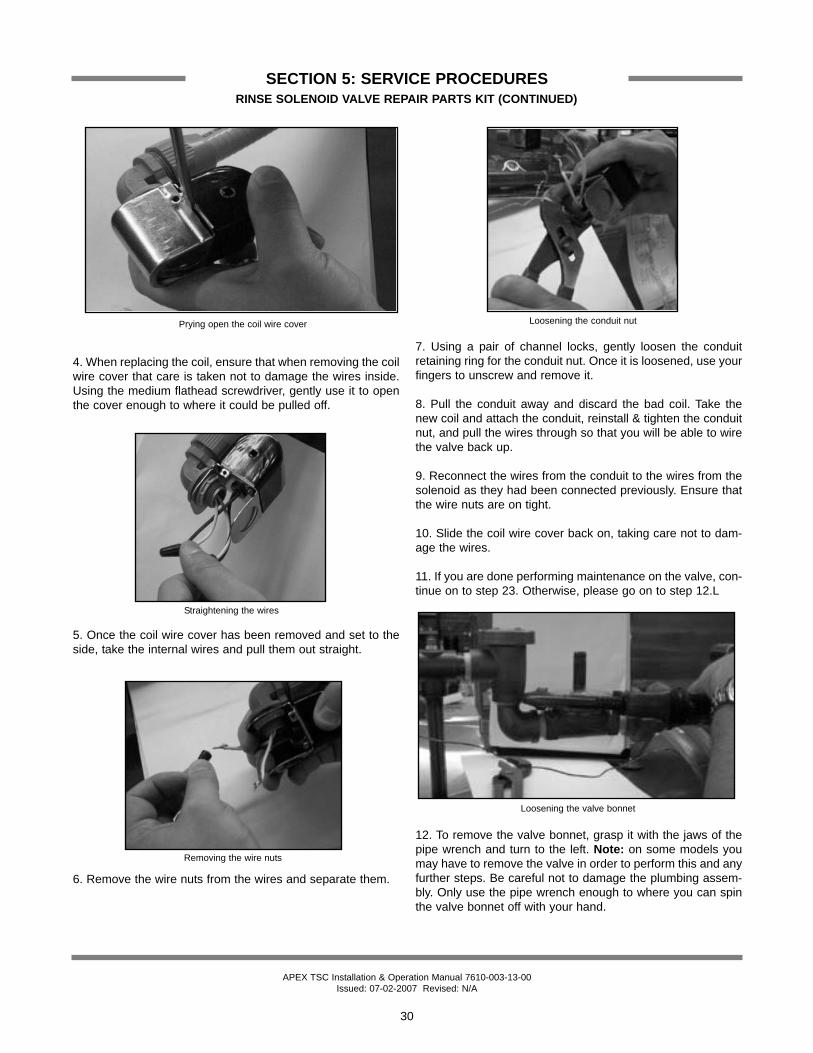
4. When replacing the coil, ensure that when removing the coilwire cover that care is taken not to damage the wires inside.Using the medium flathead screwdriver, gently use it to openthe cover enough to where it could be pulled off.
5. Once the coil wire cover has been removed and set to theside, take the internal wires and pull them out straight.
6. Remove the wire nuts from the wires and separate them.
7. Using a pair of channel locks, gently loosen the conduitretaining ring for the conduit nut. Once it is loosened, use yourfingers to unscrew and remove it.
8. Pull the conduit away and discard the bad coil. Take thenew coil and attach the conduit, reinstall & tighten the conduitnut, and pull the wires through so that you will be able to wirethe valve back up.
9. Reconnect the wires from the conduit to the wires from thesolenoid as they had been connected previously. Ensure thatthe wire nuts are on tight.
10. Slide the coil wire cover back on, taking care not to dam-age the wires.
11. If you are done performing maintenance on the valve, con-tinue on to step 23. Otherwise, please go on to step 12.L
12. To remove the valve bonnet, grasp it with the jaws of thepipe wrench and turn to the left. Note: on some models youmay have to remove the valve in order to perform this and anyfurther steps. Be careful not to damage the plumbing assem-bly. Only use the pipe wrench enough to where you can spinthe valve bonnet off with your hand.
Prying open the coil wire cover
Straightening the wires
Loosening the conduit nut
Removing the wire nuts
Loosening the valve bonnet

APEX TSC Installation & Operation Manual 7610-003-13-00Issued: 07-02-2007 Revised: N/A
SECTION 5: SERVICE PROCEDURESRINSE SOLENOID VALVE REPAIR PARTS KIT (CONTINUED)
31
13. Slowly remove the valve bonnet. Note: The spring for theplunger is located directly under the bonnet and may comefree if you are not careful. Remove the plunger, spring andvalve bonnet and place to the side.
14. Remove the O-ring and inspect it. If it has any tears or cutsor excessive flat spaces, it should be replaced.
15. Examine the threads for the valve bonnet. Check them forscoring or signs of damage. Take a cloth and clean them outto remove any foreign particles that might get lodged in thethreads and cause a leak. Severely damage threads shouldnot be repaired; instead it is recommended that the entirevalve should be replaced. These instructions do not provideinformation on replacing the solenoid valve.
16. Note: Even though an O-ring may not appear damaged, itis a good idea to go ahead and replace it if you have a newone. This will help ensure that your valve remains leak-free inthe future!
17. Remove the diaphragm retainer and then the diaphragmitself. Many problems associated with a solenoid valve can betraced to a clogged pilot port in the diaphragm.
18. As indicated in the photo above, the extension hole canbecome clogged. If it is difficult to clean out, you can use aheated straight pin to push through the hole. The center hole,the pilot port, must also be clear. If the diaphragm is torn orbent in any way, it must be replaced.
Removing the valve bonnet
Removing the O-ring
Removing the diaphragm
Pointing out the extension hole
21
Diaphragm showing (1) pilot port and (2) extension hole
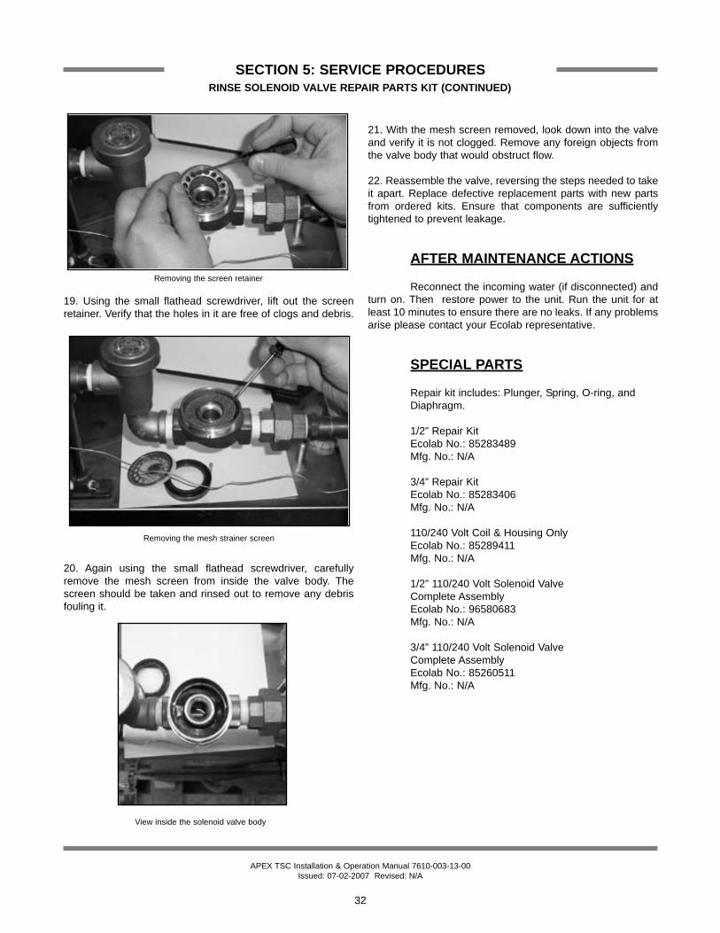
APEX TSC Installation & Operation Manual 7610-003-13-00Issued: 07-02-2007 Revised: N/A
SECTION 5: SERVICE PROCEDURESRINSE SOLENOID VALVE REPAIR PARTS KIT (CONTINUED)
32
19. Using the small flathead screwdriver, lift out the screenretainer. Verify that the holes in it are free of clogs and debris.
20. Again using the small flathead screwdriver, carefullyremove the mesh screen from inside the valve body. Thescreen should be taken and rinsed out to remove any debrisfouling it.
21. With the mesh screen removed, look down into the valveand verify it is not clogged. Remove any foreign objects fromthe valve body that would obstruct flow.
22. Reassemble the valve, reversing the steps needed to takeit apart. Replace defective replacement parts with new partsfrom ordered kits. Ensure that components are sufficientlytightened to prevent leakage.
AFTER MAINTENANCE ACTIONS
Reconnect the incoming water (if disconnected) andturn on. Then restore power to the unit. Run the unit for atleast 10 minutes to ensure there are no leaks. If any problemsarise please contact your Ecolab representative.
SPECIAL PARTS
Repair kit includes: Plunger, Spring, O-ring, and Diaphragm.
1/2” Repair KitEcolab No.: 85283489Mfg. No.: N/A
3/4” Repair KitEcolab No.: 85283406Mfg. No.: N/A
110/240 Volt Coil & Housing OnlyEcolab No.: 85289411 Mfg. No.: N/A
1/2” 110/240 Volt Solenoid Valve Complete AssemblyEcolab No.: 96580683 Mfg. No.: N/A
3/4” 110/240 Volt Solenoid Valve Complete Assembly Ecolab No.: 85260511Mfg. No.: N/A
Removing the screen retainer
Removing the mesh strainer screen
View inside the solenoid valve body

APEX TSC Installation & Operation Manual 7610-003-13-00Issued: 07-02-2007 Revised: N/A
SECTION 5: SERVICE PROCEDURESVACUUM BREAKER REPAIR PARTS KIT
33
These dishmachines are equipped with vacuumbreakers to serve as back-flow prevention devices. ASSErequirements specify what type of back-flow prevention is nec-essary on dishmachines. Vacuum breakers, unlike air gaps,have certain parts that have specific tolerances and designaspects that must be met in order to function properly.
Ecolab offers repair kits for replacing some of thewear items associated with vacuum breakers which will allowyou to save money in that replacement of these parts can takeplace without removing the vacuum breaker from the plumb-ing assembly.
The instructions provided here are for maintenancepersonnel only. Unauthorized persons should not attempt anyof the steps contained in these instructions.
Warning: many of the instructions and stepswithin this document require the use of tools. Only autho-rized personnel should ever perform any maintenanceprocedure on the dishmachine!
PREPARATION
1. Power must be secured to the unit at the servicebreaker. Tag or lock out the service breaker to prevent acci-dental or unauthorized energizing of the machine.
2. Ensure that incoming water to the machine issecured either by use of a shut-off valve or disconnecting theincoming water line.
TOOLS REQUIRED
The following tools will be needed to perform thismaintenance evolution:
1. Small flathead screwdriver2. Needle nose pliers
TIME REQUIRED
It is estimated that it will take (1) person twenty min-utes to perform this task, not including all of the items indicat-ed in the section entitled “PREPARATION”.
IMPORTANT NOTES
1. Read these instructions thoroughly before attempt-ing this maintenance evolution. Become familiar with the partsand what actions need to be taken. This will save time in thelong run!
STEPS
1. Note: These instructions only apply to vacuum breakers(1/2” NPT and 3/4” NPT) as pictured below. The repair kitsindicated in these instructions will only work on those style ofback-flow preventers. If you have a machine with a differentstyle of vacuum breaker, contact your Ecolab representativeabout replacement components.
2. Note: Even though the photos in these instructions show avacuum breaker that has been removed from the plumbingassembly, these maintenance steps could be performed with itinstalled so long as the requirements in the section entitled“PREPARATION” have been met.
3. Remove the top cap by gripping firmly and turning to theleft. The cap should come off after a few turns.
4. Set the cap to the side.
5. Using the needle nose pliers, gently lift out the plunger andset to the side. Examine the brass seating surface inside thevacuum breaker. The plunger is required to sit flat on this sur-face so it must be free of defects, imperfections and the like. Ifthere is debris, remove it. If it is chipped or cracked then thevacuum breaker must be replaced. Failure to do so may resultin the vacuum breaker not working according to its design andcould result in damage to the dishmachine.
Vacuum breaker
Removing the cap
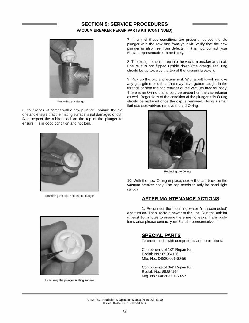
APEX TSC Installation & Operation Manual 7610-003-13-00Issued: 07-02-2007 Revised: N/A
SECTION 5: SERVICE PROCEDURESVACUUM BREAKER REPAIR PARTS KIT (CONTINUED)
34
6. Your repair kit comes with a new plunger. Examine the oldone and ensure that the mating surface is not damaged or cut.Also inspect the rubber seal on the top of the plunger toensure it is in good condition and not torn.
7. If any of these conditions are present, replace the oldplunger with the new one from your kit. Verify that the newplunger is also free from defects. If it is not, contact yourEcolab representative immediately.
8. The plunger should drop into the vacuum breaker and seat.Ensure it is not flipped upside down (the orange seal ringshould be up towards the top of the vacuum breaker).
9. Pick up the cap and examine it. With a soft towel, removeany grit, grime or debris that may have gotten caught in thethreads of both the cap retainer or the vacuum breaker body.There is an O-ring that should be present on the cap retaineras well. Regardless of the condition of the plunger, this O-ringshould be replaced once the cap is removed. Using a smallflathead screwdriver, remove the old O-ring.
10. With the new O-ring in place, screw the cap back on thevacuum breaker body. The cap needs to only be hand tight(snug).
AFTER MAINTENANCE ACTIONS
1. Reconnect the incoming water (if disconnected)and turn on. Then restore power to the unit. Run the unit forat least 10 minutes to ensure there are no leaks. If any prob-lems arise please contact your Ecolab representative.
SPECIAL PARTSTo order the kit with components and instructions:
Components of 1/2” Repair KitEcolab No.: 85284156Mfg. No.: 04820-001-60-56
Components of 3/4” Repair KitEcolab No.: 85284164Mfg. No.: 04820-001-60-57
Removing the plunger
Examining the seal ring on the plunger
Examining the plunger seating surface
Replacing the O-ring
35
SECTION 6:PARTS SECTION
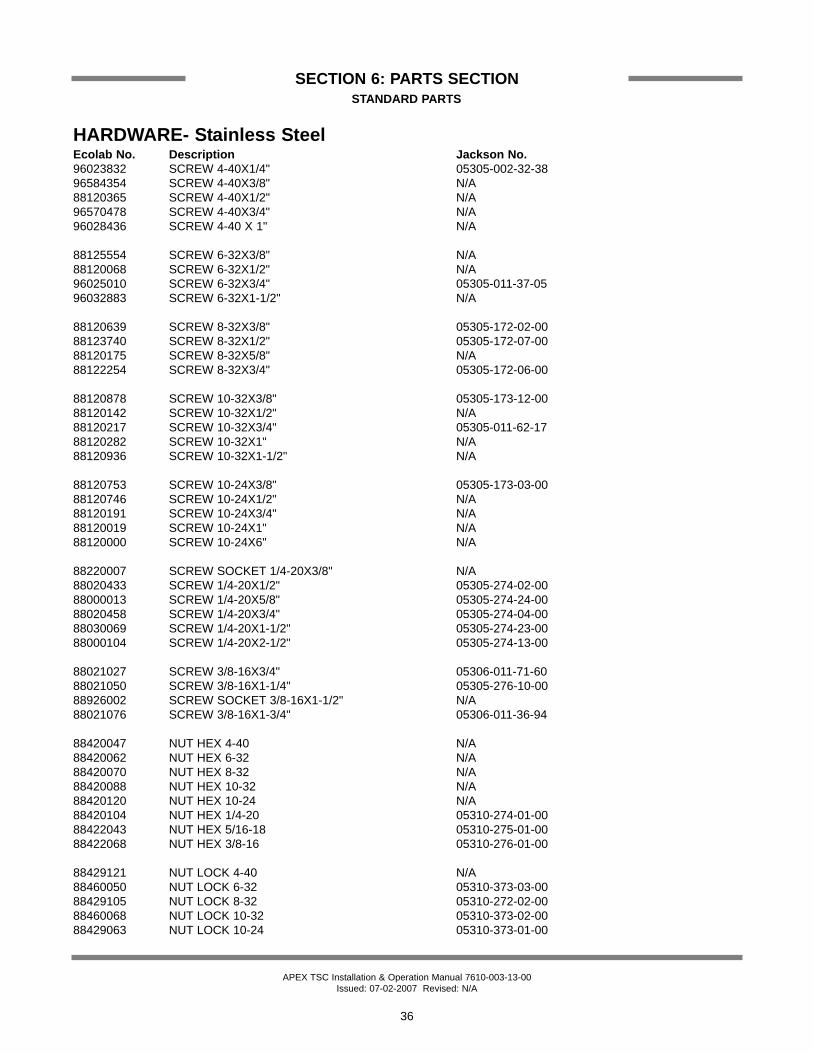
APEX TSC Installation & Operation Manual 7610-003-13-00Issued: 07-02-2007 Revised: N/A
SECTION 6: PARTS SECTIONSTANDARD PARTS
36
HARDWARE- Stainless SteelEcolab No. Description Jackson No.96023832 SCREW 4-40X1/4" 05305-002-32-3896584354 SCREW 4-40X3/8" N/A88120365 SCREW 4-40X1/2" N/A96570478 SCREW 4-40X3/4" N/A96028436 SCREW 4-40 X 1" N/A
88125554 SCREW 6-32X3/8" N/A88120068 SCREW 6-32X1/2" N/A96025010 SCREW 6-32X3/4" 05305-011-37-0596032883 SCREW 6-32X1-1/2" N/A
88120639 SCREW 8-32X3/8" 05305-172-02-0088123740 SCREW 8-32X1/2" 05305-172-07-0088120175 SCREW 8-32X5/8" N/A88122254 SCREW 8-32X3/4" 05305-172-06-00
88120878 SCREW 10-32X3/8" 05305-173-12-0088120142 SCREW 10-32X1/2" N/A88120217 SCREW 10-32X3/4" 05305-011-62-1788120282 SCREW 10-32X1" N/A88120936 SCREW 10-32X1-1/2" N/A
88120753 SCREW 10-24X3/8" 05305-173-03-0088120746 SCREW 10-24X1/2" N/A88120191 SCREW 10-24X3/4" N/A88120019 SCREW 10-24X1" N/A88120000 SCREW 10-24X6" N/A
88220007 SCREW SOCKET 1/4-20X3/8" N/A88020433 SCREW 1/4-20X1/2" 05305-274-02-0088000013 SCREW 1/4-20X5/8" 05305-274-24-0088020458 SCREW 1/4-20X3/4" 05305-274-04-0088030069 SCREW 1/4-20X1-1/2" 05305-274-23-0088000104 SCREW 1/4-20X2-1/2" 05305-274-13-00
88021027 SCREW 3/8-16X3/4" 05306-011-71-6088021050 SCREW 3/8-16X1-1/4" 05305-276-10-0088926002 SCREW SOCKET 3/8-16X1-1/2" N/A88021076 SCREW 3/8-16X1-3/4" 05306-011-36-94
88420047 NUT HEX 4-40 N/A88420062 NUT HEX 6-32 N/A88420070 NUT HEX 8-32 N/A88420088 NUT HEX 10-32 N/A88420120 NUT HEX 10-24 N/A88420104 NUT HEX 1/4-20 05310-274-01-0088422043 NUT HEX 5/16-18 05310-275-01-0088422068 NUT HEX 3/8-16 05310-276-01-00
88429121 NUT LOCK 4-40 N/A88460050 NUT LOCK 6-32 05310-373-03-0088429105 NUT LOCK 8-32 05310-272-02-0088460068 NUT LOCK 10-32 05310-373-02-0088429063 NUT LOCK 10-24 05310-373-01-00

APEX TSC Installation & Operation Manual 7610-003-13-00Issued: 07-02-2007 Revised: N/A
SECTION 6: PARTS SECTIONSTANDARD PARTS
37
88429113 NUT LOCK 1/4-20 05310-374-01-0088419056 NUT LOCK 5/16-18 N/A88419007 NUT LOCK 3/8-16 05310-011-72-55
88520000 WASHER FLAT 1/4 05311-002-78-9388530597 WASHER FLAT 5/16 05311-175-01-0088530605 WASHER FLAT 3/8 05311-176-01-00
88521059 WASHER LOCK #8 05311-272-01-0088521075 WASHER LOCK #10 N/A88521083 WASHER LOCK 1/4 05311-274-01-0088521117 WASHER LOCK 5/16 05311-275-01-0088521109 WASHER LOCK 3/8 05311-276-01-0088520069 WASHER LOCK 1/2 05311-011-71-9388500000 WASHER BEV 3/8 SQUARE 05311-011-35-36
88900733 PIN COTTER 1/16X1/2" 05315-011-68-5696027495 PIN COTTER 3/32X3/4" 05315-207-01-0088900501 PIN COTTER 1/8X3/4" 05315-011-60-0988930581 PIN COTTER 1/8X1-1/2" 05315-002-05-8688920087 PIN COTTER 3/16X1-3/4" N/A96035241 HAIRPIN 05315-002-15-39
HARDWARE MISC.83109041 CABLE TIE 7" 005975-602-05-1683109199 CABLE TIE 15" 100PK N/A83109025 CABLE TIE W/SCREW HOLE N/A
89990121 GREASE SILICONE 3OZ TUBE N/A89992176 SILICONE CAULK WHITE 3OZ TUBE N/A89991996 TEFLON TAPE ROLL N/A83109125 ELECTRICAL TAPE N/A
96022447 ENDCAP, DOOR HANDLE 005340-011-35-0096552336 DOOR GUIDE, PLASTIC, 23 1/2” Long 05700-111-33-59
ELECTRICAL83300541 CONDUIT 1/2" 05975-111-46-5783312017 NUT, CONDUIT 1/2" N/A83311506 CONNECTOR, CONDUIT 1/2" 05975-011-45-1383311753 ELBOW, 90DEG, CONDUIT 1/2" 05975-111-01-0083311852 ELBOW 45DEG, CONDUIT 1/2" 05975-011-45-2383115003 PLUG, PLASTIC 1/2" N/A96540067 PLUG, METAL 1/2" N/A83199570 PLUG, RUBBER 1/2" N/A83116814 PLUG, METAL 1-1/2" N/A87301412 HANGER, CONDUIT METAL N/A
96203153 TERMINAL FEMALE 1/4" W/PIGGY BACK N/A83100002 TERMINAL FEMALE 1/4" 14-8GA N/A83102269 TERMINAL FEMALE 1/4" 16-14GA N/A83102244 TERMINAL FEMALE 1/4" 22-18GA N/A83101022 CONNECTOR BUTT SPLICE 16-14GA N/A83101014 CONNECTOR BUTT SPLICE 22-18GA N/A83102152 TERMINAL SPADE #8HOLE 16-14GA N/A83102129 TERMINAL SPADE #8HOLE 22-16GA N/A
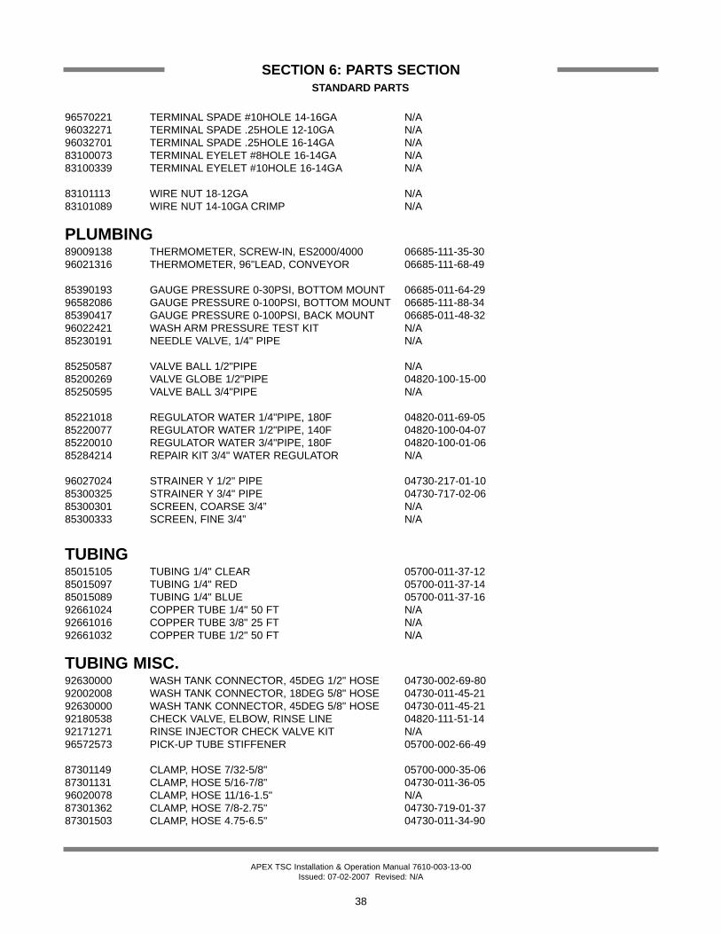
APEX TSC Installation & Operation Manual 7610-003-13-00Issued: 07-02-2007 Revised: N/A
SECTION 6: PARTS SECTIONSTANDARD PARTS
38
96570221 TERMINAL SPADE #10HOLE 14-16GA N/A96032271 TERMINAL SPADE .25HOLE 12-10GA N/A96032701 TERMINAL SPADE .25HOLE 16-14GA N/A83100073 TERMINAL EYELET #8HOLE 16-14GA N/A83100339 TERMINAL EYELET #10HOLE 16-14GA N/A
83101113 WIRE NUT 18-12GA N/A83101089 WIRE NUT 14-10GA CRIMP N/A
PLUMBING89009138 THERMOMETER, SCREW-IN, ES2000/4000 06685-111-35-3096021316 THERMOMETER, 96"LEAD, CONVEYOR 06685-111-68-49
85390193 GAUGE PRESSURE 0-30PSI, BOTTOM MOUNT 06685-011-64-2996582086 GAUGE PRESSURE 0-100PSI, BOTTOM MOUNT 06685-111-88-3485390417 GAUGE PRESSURE 0-100PSI, BACK MOUNT 06685-011-48-3296022421 WASH ARM PRESSURE TEST KIT N/A85230191 NEEDLE VALVE, 1/4" PIPE N/A
85250587 VALVE BALL 1/2"PIPE N/A85200269 VALVE GLOBE 1/2"PIPE 04820-100-15-0085250595 VALVE BALL 3/4"PIPE N/A
85221018 REGULATOR WATER 1/4"PIPE, 180F 04820-011-69-0585220077 REGULATOR WATER 1/2"PIPE, 140F 04820-100-04-0785220010 REGULATOR WATER 3/4"PIPE, 180F 04820-100-01-0685284214 REPAIR KIT 3/4" WATER REGULATOR N/A
96027024 STRAINER Y 1/2" PIPE 04730-217-01-1085300325 STRAINER Y 3/4" PIPE 04730-717-02-0685300301 SCREEN, COARSE 3/4” N/A85300333 SCREEN, FINE 3/4” N/A
TUBING85015105 TUBING 1/4" CLEAR 05700-011-37-1285015097 TUBING 1/4" RED 05700-011-37-1485015089 TUBING 1/4" BLUE 05700-011-37-1692661024 COPPER TUBE 1/4" 50 FT N/A92661016 COPPER TUBE 3/8" 25 FT N/A92661032 COPPER TUBE 1/2" 50 FT N/A
TUBING MISC.92630000 WASH TANK CONNECTOR, 45DEG 1/2" HOSE 04730-002-69-8092002008 WASH TANK CONNECTOR, 18DEG 5/8" HOSE 04730-011-45-2192630000 WASH TANK CONNECTOR, 45DEG 5/8" HOSE 04730-011-45-2192180538 CHECK VALVE, ELBOW, RINSE LINE 04820-111-51-1492171271 RINSE INJECTOR CHECK VALVE KIT N/A96572573 PICK-UP TUBE STIFFENER 05700-002-66-49
87301149 CLAMP, HOSE 7/32-5/8" 05700-000-35-0687301131 CLAMP, HOSE 5/16-7/8" 04730-011-36-0596020078 CLAMP, HOSE 11/16-1.5" N/A87301362 CLAMP, HOSE 7/8-2.75" 04730-719-01-3787301503 CLAMP, HOSE 4.75-6.5" 04730-011-34-90

APEX TSC Installation & Operation Manual 7610-003-13-00Issued: 07-02-2007 Revised: N/A
SECTION 6: PARTS SECTIONCHEMICAL FEEDER PUMP ASSEMBLY
39
Roller, Red (Detergent/Sanitizer)Ecolab No.: 96037924
Mfg. No.: 04320-111-36-70
Roller, White (Rinse Aid)Ecolab No.: 84800041
Mfg. No.: 04320-002-82-28
Roller, Black Ecolab No.: 96029533
Mfg. No.: 04320-111-65-27
Housing Kit (Red roller)Ecolab No.: 96562871
Mfg. No.: 04320-121-37-10
1/4” Sight Tube Ecolab No.: 92001017 Mfg. No.: N/A3/8” Sight Tube Ecolab No.: 96569496 Mfg. No.: 05700-111-35-33
Squeeze Tube Lubricant Ecolab No.: 89990121
Squeeze Tube, Detergent/Sanitizer(Use with the red roller.)Ecolab No.: 96562673
Mfg. No.: 05700-111-35-29
Clear Squeeze Tube, Rinse Aid(Use with the white roller.)
Ecolab No.: 85017119Mfg. No.: 05700-011-76-41
Tube, Small 7/32” (Use with the black roller.)
Ecolab No.: 85016079Mfg. No.: 05700-011-65-21
Motor, 36 RPM 115V Detergent/Sanitizer Feeder Pump
Ecolab No.: 83740209 Mfg. No.: 04320-111-35-14
Motor, 14 RPM 115V Rinse Aid Feeder PumpEcolab No.: 83740282
Mfg. No.: 04320-111-35-13
Motor, 36 RPM 240V Detergent/Sanitizer Feeder Pump
Ecolab No.: 96029293 Mfg. No.: 04320-111-47-47
Motor, 14 RPM 240V Rinse Aid Feeder PumpEcolab No.: 96029897
Mfg. No.: 04320-111-47-46
Motor, 14 RPM 24V Rinse Aid Feeder PumpEcolab No.: 96030317
Mfg. No.: 04320-011-63-33
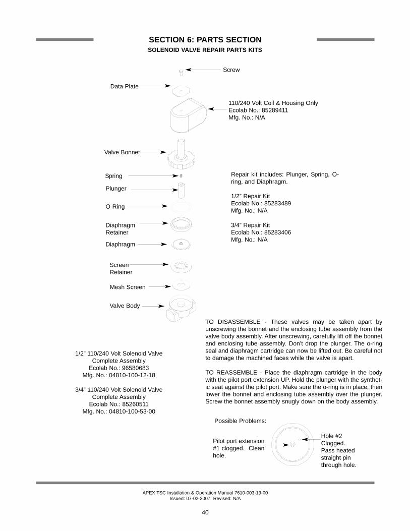
APEX TSC Installation & Operation Manual 7610-003-13-00Issued: 07-02-2007 Revised: N/A
SECTION 6: PARTS SECTIONSOLENOID VALVE REPAIR PARTS KITS
40
Screw
Data Plate
110/240 Volt Coil & Housing OnlyEcolab No.: 85289411 Mfg. No.: N/A
Valve Bonnet
DiaphragmRetainer
Diaphragm
O-Ring
Plunger
Spring
Screen Retainer
Mesh Screen
Valve Body
1/2” 110/240 Volt Solenoid ValveComplete Assembly
Ecolab No.: 96580683 Mfg. No.: 04810-100-12-18
3/4” 110/240 Volt Solenoid Valve Complete Assembly
Ecolab No.: 85260511Mfg. No.: 04810-100-53-00
TO DISASSEMBLE - These valves may be taken apart byunscrewing the bonnet and the enclosing tube assembly from thevalve body assembly. After unscrewing, carefully lift off the bonnetand enclosing tube assembly. Don’t drop the plunger. The o-ringseal and diaphragm cartridge can now be lifted out. Be careful notto damage the machined faces while the valve is apart.
TO REASSEMBLE - Place the diaphragm cartridge in the bodywith the pilot port extension UP. Hold the plunger with the synthet-ic seat against the pilot port. Make sure the o-ring is in place, thenlower the bonnet and enclosing tube assembly over the plunger.Screw the bonnet assembly snugly down on the body assembly.
Pilot port extension#1 clogged. Cleanhole.
Possible Problems:
Hole #2Clogged.Pass heatedstraight pinthrough hole.
Repair kit includes: Plunger, Spring, O-ring, and Diaphragm.
1/2” Repair KitEcolab No.: 85283489Mfg. No.: N/A
3/4” Repair KitEcolab No.: 85283406Mfg. No.: N/A
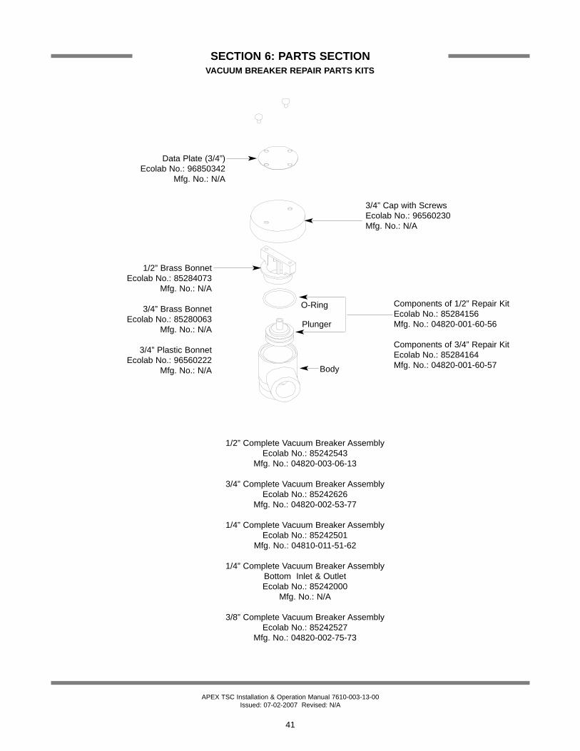
APEX TSC Installation & Operation Manual 7610-003-13-00Issued: 07-02-2007 Revised: N/A
SECTION 6: PARTS SECTIONVACUUM BREAKER REPAIR PARTS KITS
41
1/2” Complete Vacuum Breaker Assembly Ecolab No.: 85242543
Mfg. No.: 04820-003-06-13
3/4” Complete Vacuum Breaker Assembly Ecolab No.: 85242626
Mfg. No.: 04820-002-53-77
1/4” Complete Vacuum Breaker Assembly Ecolab No.: 85242501
Mfg. No.: 04810-011-51-62
1/4” Complete Vacuum Breaker Assembly Bottom Inlet & OutletEcolab No.: 85242000
Mfg. No.: N/A
3/8” Complete Vacuum Breaker Assembly Ecolab No.: 85242527
Mfg. No.: 04820-002-75-73
Components of 1/2” Repair KitEcolab No.: 85284156Mfg. No.: 04820-001-60-56
Components of 3/4” Repair KitEcolab No.: 85284164Mfg. No.: 04820-001-60-57
Data Plate (3/4”)Ecolab No.: 96850342
Mfg. No.: N/A
3/4” Cap with ScrewsEcolab No.: 96560230Mfg. No.: N/A
O-Ring
Plunger
Body
1/2” Brass BonnetEcolab No.: 85284073
Mfg. No.: N/A
3/4” Brass BonnetEcolab No.: 85280063
Mfg. No.: N/A
3/4” Plastic BonnetEcolab No.: 96560222
Mfg. No.: N/A

APEX TSC Installation & Operation Manual 7610-003-13-00Issued: 07-02-2007 Revised: N/A
SECTION 6: PARTS SECTIONUPPER CONTROL BOX ASSEMBLY
42
413 2
10
7
8
* Represents an item not visible.
9
Decal, KeypadEcolab No.: 96633732
Mfg. No.: 09905-003-37-32
5
11
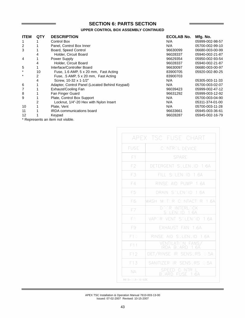
APEX TSC Installation & Operation Manual 7610-003-13-00Issued: 07-02-2007 Revised: 10-15-2007
SECTION 6: PARTS SECTIONUPPER CONTROL BOX ASSEMBLY CONTINUED
43
ITEM QTY DESCRIPTION ECOLAB No. Mfg. No.1 1 Control Box N/A 05999-002-98-572 1 Panel, Control Box Inner N/A 05700-002-99-103 1 Board, Speed Control 96630099 06680-003-00-99
4 Holder, Circuit Board 96028337 05940-002-21-874 1 Power Supply 96629354 05950-002-93-54
4 Holder, Circuit Board 96028337 05940-002-21-875 1 Interface/Controller Board 96630097 06680-003-00-97* 10 Fuse, 1.6 AMP, 5 x 20 mm, Fast Acting 83900705 05920-002-80-25* 2 Fuse, .5 AMP, 5 x 20 mm, Fast Acting 83900703
4 Screw, 10-32 x 1-1/2” N/A 05305-003-11-336 1 Adapter, Control Panel (Located Behind Keypad) N/A 05700-003-02-077 1 Exhaust/Cooling Fan 96039423 05999-002-47-128 1 Fan Finger Guard 96631292 05999-003-12-929 1 Plate, Control Box Support N/A 05700-003-04-90
2 Locknut, 1/4”-20 Hex with Nylon Insert N/A 05311-374-01-0010 1 Plate, Vent N/A 05700-003-11-2811 1 IRDA communications board 96633661 05945-003-36-6112 1 Keypad 96028287 05945-002-16-79* Represents an item not visible.
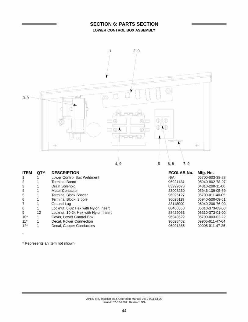
APEX TSC Installation & Operation Manual 7610-003-13-00Issued: 07-02-2007 Revised: N/A
SECTION 6: PARTS SECTIONLOWER CONTROL BOX ASSEMBLY
1 2, 9
3, 9
5 6, 8 7, 94, 9
44
ITEM QTY DESCRIPTION ECOLAB No. Mfg. No.1 1 Lower Control Box Weldment N/A 05700-003-38-282 1 Terminal Board 96021134 05940-002-78-973 1 Drain Solenoid 83999078 04810-200-11-004 1 Motor Contactor 83008250 05945-109-05-695 1 Terminal Block Spacer 96025127 05700-011-40-056 1 Terminal Block, 2 pole 96025119 05940-500-09-617 1 Ground Lug 83118000 05940-200-76-008 1 Locknut, 6-32 Hex with Nylon Insert 88460050 05310-373-03-009 12 Locknut, 10-24 Hex with Nylon Insert 88429063 05310-373-01-0010* 1 Cover, Lower Control Box 96040522 05700-003-02-2211* 1 Decal, Power Connection 96028402 09905-011-47-6412* 1 Decal, Copper Conductors 96021365 09905-011-47-35
`
* Represents an item not shown.
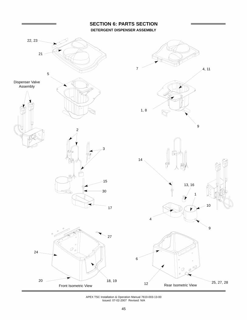
APEX TSC Installation & Operation Manual 7610-003-13-00Issued: 07-02-2007 Revised: N/A
SECTION 6: PARTS SECTIONDETERGENT DISPENSER ASSEMBLY
45
Front Isometric View Rear Isometric View
22, 23
21
5
Dispenser Valve Assembly
3
2
15
30
17
27
18, 1920
24
14
7
1, 8
9
4, 11
13, 16
25, 27, 2812
1
9
10
4
6

APEX TSC Installation & Operation Manual 7610-003-13-00Issued: 07-02-2007 Revised: 10-15-2007
SECTION 6: PARTS SECTIONDETERGENT DISPENSER ASSEMBLY (CONTINUED)
46
ITEM QTY DESCRIPTION ECOLAB No. Mfg. No.Complete Assembly N/A 05700-003-04-71
*1 1 Rinse Screen 96200324 05700-011-48-912 2 Low Product Sensor Receiver 96627389 05945-002-73-893 2 Low Product Sensor Emitter 96627390 05945-002-73-904 1 Detergent Screen 96633494 04320-003-34-945 1 Product Guide 96630150 09330-002-72-366 1 Lid Switch 96633520 05930-003-35-207 1 Lid Magnet 96633522 05930-003-35-22*8 1 Rinse Spray Nozzle 85312098 04730-002-74-009 2 Connector, 1/4” Tube x 3/8” Tube 96627479 04730-002-74-7910 1 Rinse Spray Housing 96627238 09330-002-72-3811 1 4.3W, Detergent Spray Nozzle 85312726 04320-003-35-15*12 1 Gasket, Detergent To Tablet Dispenser N/A 05330-003-02-4913 1 Nut, Lock 92109164 05310-002-74-0214 1 Flow Indicator 92183086 05700-011-50-1415 1 Foot, Filter 92232037 04730-002-74-0116 1 Float Switch 83053082 05930-011-48-9817 1 Rinse Sump 96627237 09330-002-72-37*18 1 LED, Red 83440552 05945-002-76-10*19 1 Decal, Dispenser 96630096 09905-003-03-93*20 1 Gasket, Dispenser to Hood N/A 05330-003-02-4621 1 Dispenser Cover 96630078 09330-003-00-9222 1 Hinge 96627241 05700-002-72-4123 1 Hinge Spacer Plate 96627242 05700-002-72-4224 1 Dispenser Base 96630091 09330-003-00-91*25 1 Hose, 5/8” x 45” 96627868 05700-002-78-68*26 1 Elbow, 3/4” Hosebarb N/A 04730-002-78-1227 1 Washer, Bonded Sealing 1/4” x 3/4” OD N/A 05311-002-77-79*28 1 Hose, 5/8” x 9 1/2” N/A 05700-003-04-89*29 1 Connector, 15 Pin Cap N/A 05999-002-77-8430 1 Insert, PP 1/4” Tube 96582248 04730-011-48-88*31 1 Seal, 15 Pin Blue Wire N/A 05999-002-77-86*32 1 Plug, Sealing N/A 05999-002-77-90* Represents an item not shown
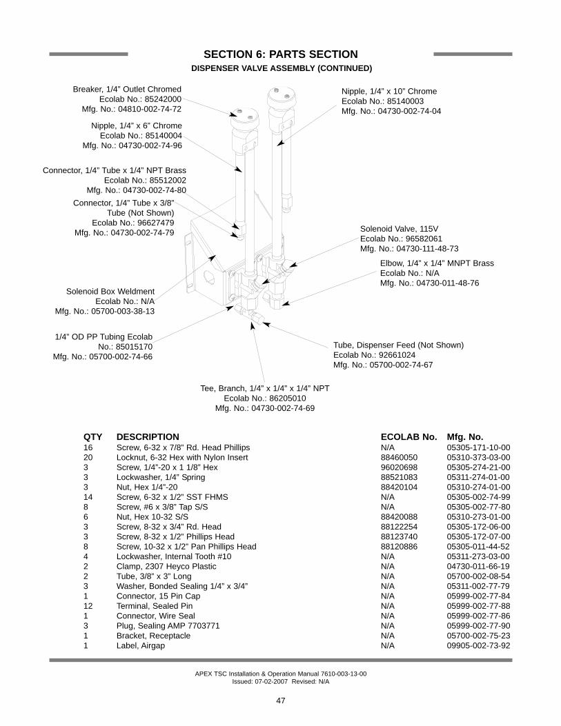
APEX TSC Installation & Operation Manual 7610-003-13-00Issued: 07-02-2007 Revised: N/A
SECTION 6: PARTS SECTIONDISPENSER VALVE ASSEMBLY (CONTINUED)
47
QTY DESCRIPTION ECOLAB No. Mfg. No.16 Screw, 6-32 x 7/8” Rd. Head Phillips N/A 05305-171-10-0020 Locknut, 6-32 Hex with Nylon Insert 88460050 05310-373-03-003 Screw, 1/4”-20 x 1 1/8” Hex 96020698 05305-274-21-003 Lockwasher, 1/4” Spring 88521083 05311-274-01-003 Nut, Hex 1/4”-20 88420104 05310-274-01-0014 Screw, 6-32 x 1/2” SST FHMS N/A 05305-002-74-998 Screw, #6 x 3/8” Tap S/S N/A 05305-002-77-806 Nut, Hex 10-32 S/S 88420088 05310-273-01-003 Screw, 8-32 x 3/4” Rd. Head 88122254 05305-172-06-003 Screw, 8-32 x 1/2” Phillips Head 88123740 05305-172-07-008 Screw, 10-32 x 1/2” Pan Phillips Head 88120886 05305-011-44-524 Lockwasher, Internal Tooth #10 N/A 05311-273-03-002 Clamp, 2307 Heyco Plastic N/A 04730-011-66-192 Tube, 3/8” x 3” Long N/A 05700-002-08-543 Washer, Bonded Sealing 1/4” x 3/4” N/A 05311-002-77-791 Connector, 15 Pin Cap N/A 05999-002-77-8412 Terminal, Sealed Pin N/A 05999-002-77-881 Connector, Wire Seal N/A 05999-002-77-863 Plug, Sealing AMP 7703771 N/A 05999-002-77-901 Bracket, Receptacle N/A 05700-002-75-231 Label, Airgap N/A 09905-002-73-92
Solenoid Box WeldmentEcolab No.: N/A
Mfg. No.: 05700-003-38-13
1/4” OD PP Tubing EcolabNo.: 85015170
Mfg. No.: 05700-002-74-66
Connector, 1/4” Tube x 1/4” NPT Brass Ecolab No.: 85512002
Mfg. No.: 04730-002-74-80
Breaker, 1/4” Outlet ChromedEcolab No.: 85242000
Mfg. No.: 04810-002-74-72
Nipple, 1/4” x 10” ChromeEcolab No.: 85140003 Mfg. No.: 04730-002-74-04
Solenoid Valve, 115VEcolab No.: 96582061Mfg. No.: 04730-111-48-73
Tee, Branch, 1/4” x 1/4” x 1/4” NPTEcolab No.: 86205010
Mfg. No.: 04730-002-74-69
Nipple, 1/4” x 6” ChromeEcolab No.: 85140004
Mfg. No.: 04730-002-74-96
Elbow, 1/4” x 1/4” MNPT BrassEcolab No.: N/AMfg. No.: 04730-011-48-76
Tube, Dispenser Feed (Not Shown)Ecolab No.: 92661024 Mfg. No.: 05700-002-74-67
Connector, 1/4” Tube x 3/8” Tube (Not Shown)
Ecolab No.: 96627479Mfg. No.: 04730-002-74-79

APEX TSC Installation & Operation Manual 7610-003-13-00Issued: 07-02-2007 Revised: N/A
SECTION 6: PARTS SECTIONTABLET DISPENSER ASSEMBLY
48
O-ring, 6 47/64”Ecolab No.: 87206012
Mfg. No.: 05330-003-04-78
Dispenser Repair Kit(Includes everything above this line.)
Ecolab No.: 96630094 Mfg. No.: 05700-003-00-94
Hopper, Product Ecolab No.: 96630084 Mfg. No.: 09330-003-00-84
Lid, Product Ecolab No.: 96630085 Mfg. No.: 09330-003-00-85
O-ring, 5 23/64”Ecolab No.: 87206010
Mfg. No.: 05330-003-04-76
Disk, LowerEcolab No.: 96630080
Mfg. No.: 09330-003-00-80
O-ring, 5 63/64”Ecolab No.: 87206011 Mfg. No.: 05330-003-04-77
Mounting PlateEcolab No.: 96630089 Mfg. No.: 05700-003-00-89
Motor, Gear, 24V DC 21 RPMEcolab No.: 83700001
Mfg. No.: 04320-003-04-73
Sensor, EmitterEcolab No.: 83670100
Mfg. No.: 05945-003-04-74
Flange, Inlet Tube Ecolab No.: 96630087
Mfg. No.: 09330-003-00-87
O-ring, 1 63/64”Ecolab No.: 87206014
Mfg. No.: 05330-003-04-80
Decal, Solid-San DispenserEcolab No.: 96630095
Mfg. No.: 09905-003-03-94
Disk, Wiper Ecolab No.: 96630083 Mfg. No.: 09330-003-00-83
Disk, MiddleEcolab No.: 96630081
Mfg. No.: 09330-003-00-81
Disk, Upper Ecolab No.: 96630079 Mfg. No.: 09330-003-00-79
Disk, Lower Static Ecolab No.: 96630082 Mfg. No.: 09330-003-00-82
Bracket, IR Sensor Ecolab No.: 96630086 Mfg. No.: 09330-003-00-86
Sensor, ReceiverEcolab No.: 83670101 Mfg. No.: 05945-003-04-75
O-ring, 51/64” (2 per)Ecolab No.: 87206013 Mfg. No.: 05330-003-04-79
Tube, Outlet Ecolab No.: 96630090 Mfg. No.: 05700-003-00-90
Base, Sanitizer MoldedEcolab No.: 96630088 Mfg. No.: 09330-003-00-88Fan VentEcolab No.: 96039423 Mfg. No.: 05999-002-47-12

APEX TSC Installation & Operation Manual 7610-003-13-00Issued: 07-02-2007 Revised: N/A
SECTION 6: PARTS SECTIONRINSE AID BOX ASSEMBLY
49
Rinse Box WeldmentEcolab No.: N/A
Mfg. No.: 05700-003-38-26
Bracket, Rinse Box WeldmentEcolab No.: N/AMfg. No.: 05700-003-04-86
Washer, 1/4”-20 S/SEcolab No.: N/AMfg. No.: 05311-174-01-00
Locknut, 1/4”-20 Hex with Nylon InsertEcolab No.: 88429113Mfg. No.: 05310-374-01-00
Rinse Box CoverEcolab No.: N/AMfg. No.: 05700-011-49-16
Screw, 10-32 x 3/8” Phillips Truss HeadEcolab No.: 88120878Mfg. No.: 05305-173-12-00
Tubing Assembly, 1/4" X 45" BlueEcolab No.: N/AMfg. No.: 05700-003-04-88
Connect Tube Ferrule NutEcolab No.: N/AMfg. No.: 04730-609-16-00
Insert, PP for 1/4” Tube (Not Shown)Ecolab No.: N/AMfg. No.: 04730-011-48-88
Tubing Assembly, 1/4" X 88" BlueEcolab No.: N/A
Mfg. No.: 05700-003-04-87
See page entitledCHEMICAL FEEDER
PUMP ASSEMBLY
Star Washer, External Tooth #10Ecolab No.: N/AMfg. No.: 05311-273-02-00

APEX TSC Installation & Operation Manual 7610-003-13-00Issued: 07-02-2007 Revised: 07-25-2007
SECTION 6: PARTS SECTIONHOOD ASSEMBLY & ASSOCIATED PARTS
50
Air Gap WeldmentEcolab No.: N/A
Mfg. No.: 05700-002-81-70
Air Gap ShieldEcolab No.: 96028139
Mfg. No.: 05700-002-13-35
Air Gap Base GasketEcolab No.: 96027925
Mfg. No.: 05330-002-14-48
Cantilever Arm Support BracketEcolab No.: 96581244
Mfg. No.: 09515-003-15-64
Wear Button, 1/2” Dia.3 per Bracket
Ecolab No.: 96027743Mfg. No.: 05700-011-88-01
Hood Weldment with Vapor Vent Option
Ecolab No.: N/AMfg. No.: 05700-003-02-58
Hood Weldment (Shown)Ecolab No.: N/A
Mfg. No.: 05700-003-02-59
Hood Block Spacer4 per
Ecolab No.: 96628102Mfg. No.: 05700-002-81-02
Front Corner PlugEcolab No.: 96040050
Mfg. No.: 05700-002-25-00
Rear Corner PlugEcolab No.: 96040043
Mfg. No.: 05700-002-25-01
Reed SwitchEcolab No. : 96633365
Mfg. No.: 05930-003-33-65
Wall Mount BracketEcolab No.: 96632561
Mfg. No.: 05700-003-25-61Elec. Box MountEcolab No.: N/A
Mfg. No.: 05700-003-20-15
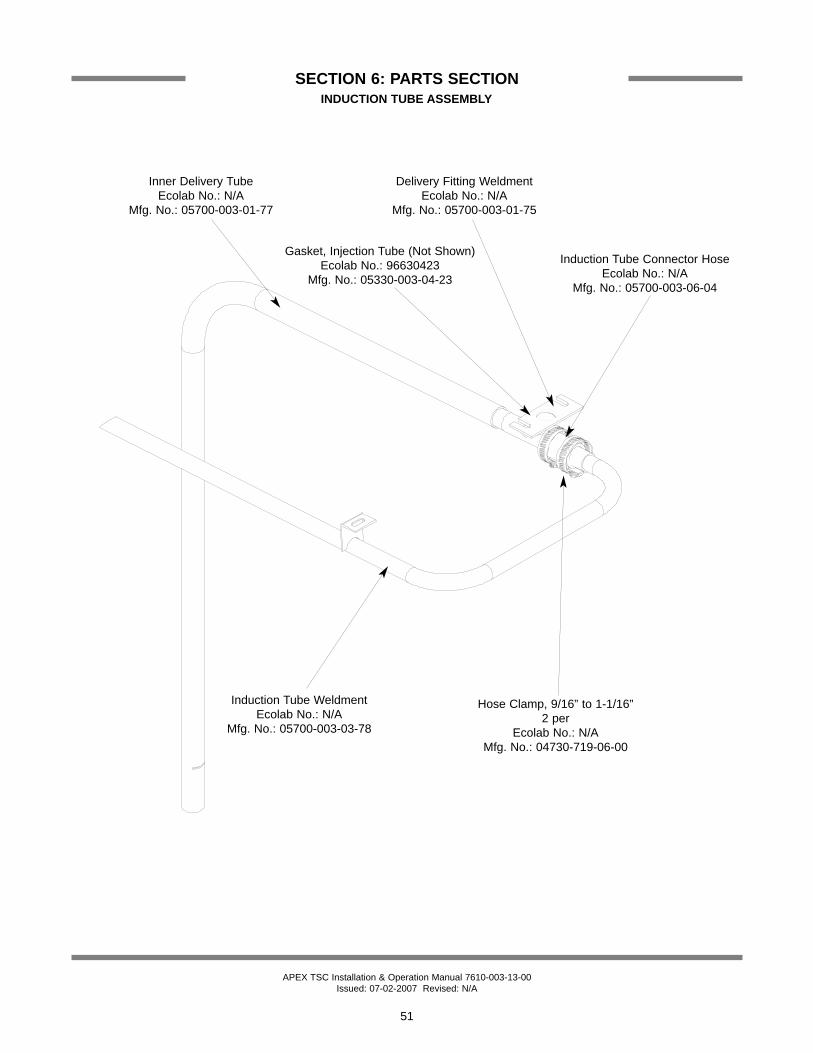
APEX TSC Installation & Operation Manual 7610-003-13-00Issued: 07-02-2007 Revised: N/A
SECTION 6: PARTS SECTIONINDUCTION TUBE ASSEMBLY
51
Inner Delivery TubeEcolab No.: N/A
Mfg. No.: 05700-003-01-77
Induction Tube WeldmentEcolab No.: N/A
Mfg. No.: 05700-003-03-78
Hose Clamp, 9/16” to 1-1/16”2 per
Ecolab No.: N/AMfg. No.: 04730-719-06-00
Delivery Fitting WeldmentEcolab No.: N/A
Mfg. No.: 05700-003-01-75
Gasket, Injection Tube (Not Shown)Ecolab No.: 96630423
Mfg. No.: 05330-003-04-23
Induction Tube Connector HoseEcolab No.: N/A
Mfg. No.: 05700-003-06-04

APEX TSC Installation & Operation Manual 7610-003-13-00Issued: 07-02-2007 Revised: N/A
SECTION 6: PARTS SECTIONTUB WELDMENT/ASSOCIATED COMPONENTS
52
Tub WeldmentEcolab No.: N/AMfg. No.: 05700-003-02-51
Temperature ProbeEcolab No.: 96038120Mfg. No.: 06680-002-16-80
Fitting, 1/4" Imperial BrassEcolab No.: 96024344Mfg. No.: 05310-924-02-05
Spillway Weldment1 per machineEcolab No.: 96583000Mfg. No.: 05700-031-37-86
Spillway Gasket1 per machineEcolab No.: 96582903Mfg. No.: 05700-111-34-52
Drain Seat Insert1 per machineEcolab No.: 96582929Mfg. No.: 05700-021-34-38
Drain Link1 per assemblyEcolab No.: 96582994Mfg. No.: 05700-031-34-45
Drain Link Connector1 per assemblyEcolab No.: 96028261Mfg. No.: 05700-002-38-10
Nut, Hex, 5/16”-181 per assemblyEcolab No.: 88419056Mfg. No.: 05310-275-01-00
Stand Pipe Weldment1 per assemblyEcolab No.: 96582747Mfg. No.: 05700-021-33-29
Stand Pipe Stopper1 per assemblyEcolab No.: 96557475Mfg. No.: 05700-121-35-54
Intake Strainer Weldment1 per machine
Ecolab No.: 96633761Mfg. No.: 05700-003-37-61
Hairpin, 1/8” x 1 15/16” S/SEcolab No.: 96035241Mfg. No.: 05315-002-15-39

APEX TSC Installation & Operation Manual 7610-003-13-00Issued: 07-02-2007 Revised: N/A
SECTION 6: PARTS SECTIONRACK RAIL ASSEMBLY/FRAME & ACCUMULATOR WELDMENTS
53
Strainer, Accumulator WeldmentEcolab No.: 96027404Mfg. No.: 05700-031-33-13
Accumulator WeldmentEcolab No.: 96028717Mfg. No.: 05700-002-19-05
Frame WeldmentEcolab No.: N/A
Mfg. No.: 05700-003-02-50
Bullet Foot4 per machine
Ecolab No.: 96552666Mfg. No.: 05340-108-01-03
Rack AssemblyEcolab No.: 96582887
Mfg. No.: 05700-031-36-76
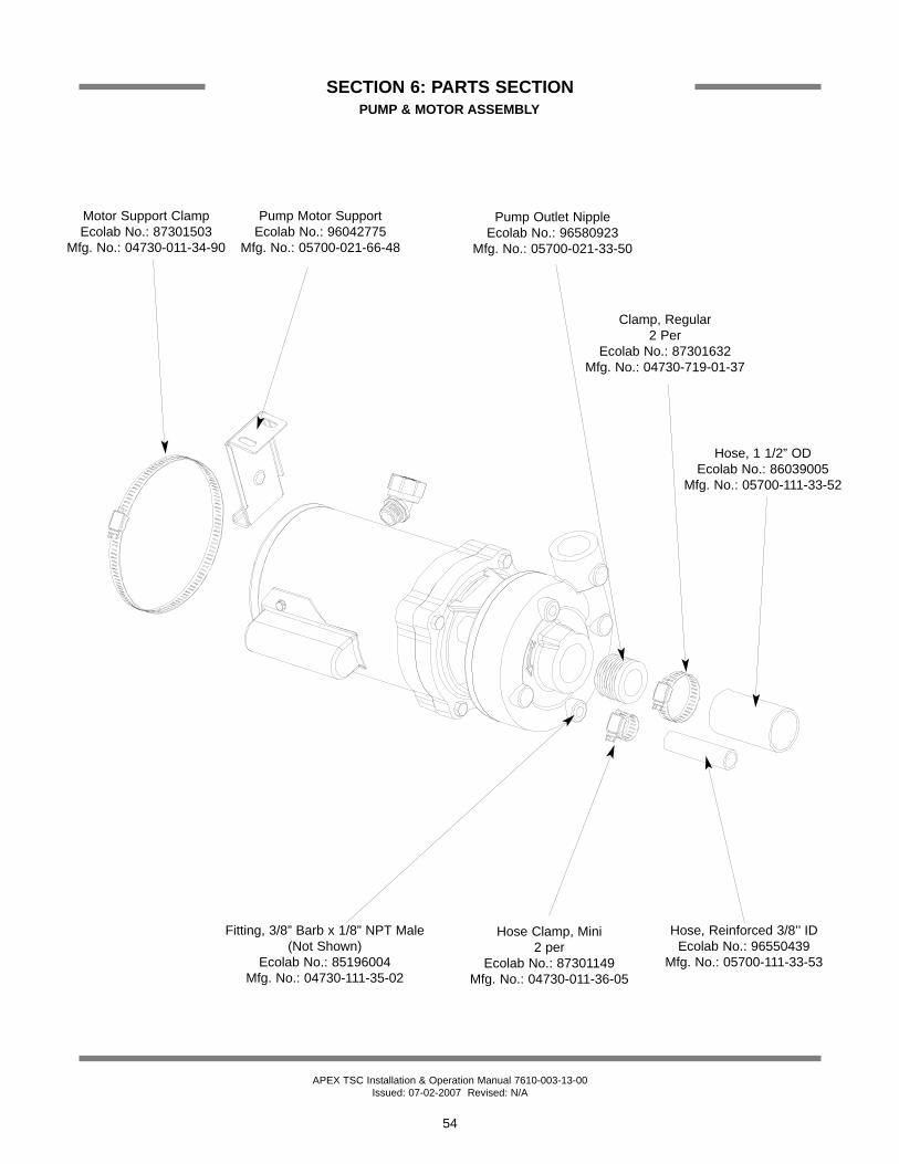
APEX TSC Installation & Operation Manual 7610-003-13-00Issued: 07-02-2007 Revised: N/A
SECTION 6: PARTS SECTIONPUMP & MOTOR ASSEMBLY
54
Fitting, 3/8” Barb x 1/8” NPT Male (Not Shown)
Ecolab No.: 85196004Mfg. No.: 04730-111-35-02
Pump Outlet NippleEcolab No.: 96580923
Mfg. No.: 05700-021-33-50
Hose, 1 1/2” ODEcolab No.: 86039005
Mfg. No.: 05700-111-33-52
Clamp, Regular 2 Per
Ecolab No.: 87301632Mfg. No.: 04730-719-01-37
Hose, Reinforced 3/8’’ IDEcolab No.: 96550439
Mfg. No.: 05700-111-33-53
Hose Clamp, Mini 2 per
Ecolab No.: 87301149Mfg. No.: 04730-011-36-05
Motor Support ClampEcolab No.: 87301503
Mfg. No.: 04730-011-34-90
Pump Motor SupportEcolab No.: 96042775
Mfg. No.: 05700-021-66-48

APEX TSC Installation & Operation Manual 7610-003-13-00Issued: 07-02-2007 Revised: N/A
SECTION 6: PARTS SECTION
55
PUMP & MOTOR ASSEMBLY (CONTINUED)
ITEM QTY DESCRIPTION ECOLAB No. Mfg. No.1 2 Pipe Plug, 1/4” NPT, Brass 86135019 04730-209-01-002 1 Volute (only available as an assembly, see item 15) N/A N/A3 1 Impeller, Stainless 96557780 05700-002-06-194 1 O-ring, Housing Seal 87203900 N/A5 1 Pump Seal 84804723 05330-002-06-216 4 Stud, Socket Head 3/8”-16 x 1 1/2” 88926002 N/A7 4 Nut, Hex, 3/8”-16 S/S 88422068 N/A8 4 Cap Screw, 3/8”-16 x 1-1/4”, S/S 88021050 N/A9 1 Bracket, Motor to Pump 96583810 N/A10 1 Slinger, Pump Shaft 96031059 N/A11 1 Shaft Adapter/Connector 96562764 N/A12 2 Allen Head Setscrew, 1/4”-20 x 1/4” 88220007 N/A13 1 Pump Motor 83710418 06105-121-35-1814 1 Pump Assembly (Items 1-12) 96562715 N/A
1
2
3
5
*4
6** 7
8
9
10
11
12
13
* Previous models used a flat gas-ket. O-ring seal can be replacedwith flat gasket. Flat gasket must bereplaced with flat gasket only.
** Apply red Loc-Tite adhesive tothreads before installation intovolute housing. Tighten using 3/16”allen wrench.

APEX TSC Installation & Operation Manual 7610-003-13-00Issued: 07-02-2007 Revised: N/A
SECTION 6: PARTS SECTIONCANTILEVER ARM/DOOR ASSEMBLIES
3
5
21
6
915, 16
17, 18
19, 11, 122021, 25
22
23, 18
7
8
4
24, 18 14
1310, 11, 12
56

APEX TSC Installation & Operation Manual 7610-003-13-00Issued: 07-02-2007 Revised: N/A
SECTION 6: PARTS SECTIONCANTILEVER ARM/DOOR ASSEMBLIES (CONTINUED)
57
ITEM QTY DESCRIPTION ECOLAB No. Mfg. No.1 1 Arm, Cantilever 96581277 05700-031-50-672 1 Spring Pin, 1/4” Dia. x 1 1/8” Long 96039185 05315-407-06-003 2 Yoke Assembly 96586615 05700-000-75-774 2 Rod, Spring 96584313 05700-002-10-525 2 Spring, Cantilever 96581285 05340-109-02-006 2 Bolt, Hanger Eye 3/8"-16 96582762 05306-956-05-007 2 Washer, Impeller 3/8” I.D. x 7/8” O.D. 96581376 05311-176-02-008 4 Nut, 3/8”-16 S/S Hex 88422068 05310-276-01-009 2 Cantilever Arm Connector 96582754 05700-011-90-9910 2 Screw, 1/4"-20 x 1 1/2" Long S/S 88030069 05305-274-23-0011 2 Washer, 1/4" ID S/S 88530589 05311-174-01-0012 2 Locknut, 1/4”-20 S/S Hex with Nylon Insert, Low Profile 96026455 05310-374-02-0013 2 Sleeve, Cantilever Arm 96582770 05700-000-85-6914 2 Plug, Cantilever Arm 96022447 05340-011-35-0015 1 Magnet, Reed Switch N/A 05930-002-68-5316 2 Locknut, 6-32 S/S Hex with Nylon Insert 88460050 05310-373-03-0017 1 Right Door Weldment with Studs 96028756 05700-002-22-2517 1 Right Door Weldment with Studs (Vapor Vent Model) N/A 05700-002-83-5418 6 Door, Guides 96552336 05700-111-33-5919 2 Screw, 1/4"-20 x 1/2" Long S/S 88020433 05305-274-02-0020 2 Spacer, PB Bolt 96582788 05700-000-29-4021 4 Locknut, 1/4”-20 S/S Hex with Nylon Insert 88429113 05310-374-01-0022 2 Door Connector Bracket 96582820 05700-021-33-3923 1 Door Only, Front 96028766 05700-002-20-0924 1 Door Only, Left Side 96028741 05700-002-20-0825* 2 Bracket, Cantilever Arm Support 96581244 05700-031-88-0026* 6 Wear Button, 1/2" Dia. UHMW 96027743 05700-011-88-01
* Represents an item not shown.

APEX TSC Installation & Operation Manual 7610-003-13-00Issued: 07-02-2007 Revised: N/A
SECTION 6: PARTS SECTIONINCOMING PLUMBING ASSEMBLY
58
Y-Strainer, 1/2"Ecolab No.: 96027024
Mfg. No.: 04730-217-01-10 Nipple, 1/2” CloseEcolab No.: 85141208
Mfg. No.: 04730-207-15-00
Nipple, 1/2” CloseEcolab No.: 85141208
Mfg. No.: 04730-207-15-00
Tee, 1/2" X 1/2" X 1/4"Ecolab No.: 96030747Mfg. No.: 04730-002-22-56
Nipple, 1/2" x 2" BrassEcolab No.: 85141224
Mfg. No.: 04730-207-19-00
Valve, Solenoid 1/2" 115VEcolab No.: 85260743Mfg. No.: 04810-100-12-18
Elbow, 1/2”, 90° StreetEcolab No.: 86075000
Mfg. No.: 04730-206-08-00
* Plug, Heyco2 per
Ecolab No.: 96024567Mfg. No.: 05975-011-47-81
* Bracket, Plumbing SupportEcolab No.: 96028816
Mfg. No.: 05700-002-28-95
Fitting, 1/4” to 1/4” Male NPTEcolab No.: 85513059
Mfg. No.: 04730-011-48-76
* Represents an item not shown.

APEX TSC Installation & Operation Manual 7610-003-13-00Issued: 07-02-2007 Revised: N/A
SECTION 6: PARTS SECTIONWASH MANIFOLD/WASH ARM ASSEMBLY
59
Lockwasher, 3/8" SplitEcolab No.: 88521109Mfg. No.: 05311-276-01-00
O Ring, Wash ManifoldEcolab No.: 87203154
Mfg. No.: 05330-111-35-15
Casting, Upper Manifold MachinedEcolab No.: 96583620
Mfg. No.: 05700-031-34-82
Nut, 3/8"-16 S/S HexEcolab No.: 88422068Mfg. No.: 05310-276-01-00
Bolt, 3/8"-16 x 1 1/4" Hex HeadEcolab No.: 88021050Mfg. No.: 05305-276-10-00
Bolt, 3/8”-16 x 1-3/4” Long (ES-4000)Ecolab No.: 88021076Mfg. No.: 5306-011-36-94
Casting, Lower Manifold MachinedEcolab No.: 96582705Mfg. No.: 05700-031-34-65
Gasket, ManifoldEcolab No.: 96552864Mfg. No.: 05700-111-35-03
Nut, 3/8"-16 S/S HexEcolab No.: 88422068Mfg. No.: 05310-276-01-00
Wash Arm End CapEcolab No.: 96552542Mfg. No.: 05700-011-35-92
Wash Arm WeldmentEcolab No.: 96582064Mfg. No.: 05700-021-63-42
Wash Arm BearingEcolab No.: 96552567
Mfg. No.: 05700-021-35-97
Wash Arm O-RingEcolab No.: 87200013
Mfg. No.: 05330-002-60-69
Manifold TubeEcolab No.: 96550338
Mfg. No.: 05700-031-34-59
* Bracket, Manifold Position Tube Ecolab No.: 96582986
Mfg. No.: 05700-011-34-63
Lockwasher, 3/8" SplitEcolab No.: 88521109Mfg. No.: 05311-276-01-00
Bolt, 3/8"-16 x 7/8" Hex HeadEcolab No.: 96033411Mfg. No.: 05306-011-36-95
O Ring, Wash ManifoldEcolab No.: 87203154
Mfg. No.: 05330-111-35-15
* Represents an item not shown.
Washer, 3/8”, Bevel, SquareEcolab No.: 88500000
Mfg. No.: 5311-011-35-36
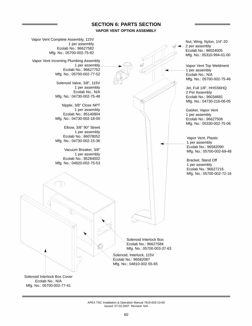
APEX TSC Installation & Operation Manual 7610-003-13-00Issued: 07-02-2007 Revised: N/A
SECTION 6: PARTS SECTIONVAPOR VENT OPTION ASSEMBLY
60
Nut, Wing, Nylon, 1/4”-202 per assemblyEcolab No.: 96024005Mfg. No.: 05310-994-01-00
Vapor Vent, Plastic1 per assemblyEcolab No.: 96582090Mfg. No.: 05700-002-69-48
Bracket, Stand Off1 per assemblyEcolab No.: 96627216Mfg. No.: 05700-002-72-16
Vapor Vent Complete Assembly, 115V1 per assembly
Ecolab No.: 96627582Mfg. No.: 05700-002-75-82
Vapor Vent Top Weldment1 per assemblyEcolab No.: N/AMfg. No.: 05700-002-75-46
Jet, Full 1/8”, HHSS6HQ2 Per AssemblyEcolab No.: 96034681Mfg. No.: 04730-216-06-05
Gasket, Vapor Vent1 per assemblyEcolab No.: 96627506Mfg. No.: 05330-002-75-06
Vapor Vent Incoming Plumbing Assembly1 per assembly
Ecolab No.: 96627752 Mfg. No.: 05700-002-77-52
Solenoid Valve, 3/8”, 115V1 per assembly
Ecolab No.: N/AMfg. No.: 04730-002-75-48
Nipple, 3/8” Close NPT1 per assembly
Ecolab No.: 85140804 Mfg. No.: 04730-002-18-00
Elbow, 3/8” 90° Street1 per assembly
Ecolab No.: 86078052 Mfg. No.: 04730-002-15-36
Vacuum Breaker, 3/8”1 per assembly
Ecolab No.: 85284002Mfg. No.: 04820-002-75-53
Solenoid, Interlock, 115VEcolab No.: 96582087Mfg. No.: 04810-002-55-65
Solenoid Interlock BoxEcolab No.: 96627584Mfg. No.: 05700-003-37-63
Solenoid Interlock Box CoverEcolab No.: N/A
Mfg. No.: 05700-002-77-41
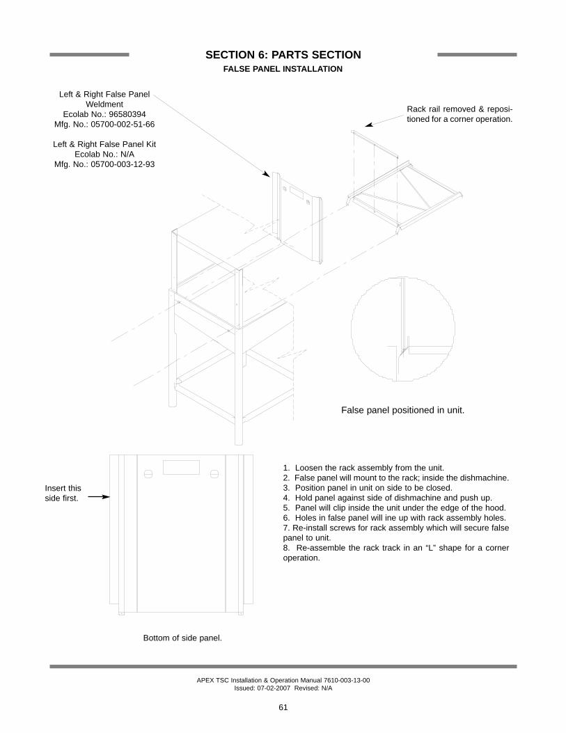
APEX TSC Installation & Operation Manual 7610-003-13-00Issued: 07-02-2007 Revised: N/A
SECTION 6: PARTS SECTION
61
FALSE PANEL INSTALLATION
1. Loosen the rack assembly from the unit.2. False panel will mount to the rack; inside the dishmachine.3. Position panel in unit on side to be closed.4. Hold panel against side of dishmachine and push up.5. Panel will clip inside the unit under the edge of the hood.6. Holes in false panel will ine up with rack assembly holes.7. Re-install screws for rack assembly which will secure falsepanel to unit.8. Re-assemble the rack track in an “L” shape for a corneroperation.
Bottom of side panel.
Insert thisside first.
False panel positioned in unit.
Rack rail removed & reposi-tioned for a corner operation.
Left & Right False PanelWeldment
Ecolab No.: 96580394Mfg. No.: 05700-002-51-66
Left & Right False Panel KitEcolab No.: N/A
Mfg. No.: 05700-003-12-93

62
SECTION 7:ELECTRICAL SCHEMATICS

APEX TSC Installation & Operation Manual 7610-003-13-00Issued: 07-02-2007 Revised: 10-15-2007
SECTION 7: ELECTRICAL SCHEMATICSAPEX TSC MACHINE & OPTIONAL VAPOR VENT 120 VOLT - 60 HERTZ - SINGLE PHASE
63

APEX TSC Installation & Operation Manual 7610-003-13-00Issued: 07-02-2007 Revised: 10-15-2007
SECTION 7: ELECTRICAL SCHEMATICSAPEX TSC MACHINE & OPTIONAL VAPOR VENT 120 VOLT - 60 HERTZ - SINGLE PHASE
64