installation, operation, service, and repair...
TRANSCRIPT

OECIOM-BD-090113
OEC Fluid Handling, Inc. 140 Cedar Springs Road Spartanburg, SC 29302
Tel: 1-800-500-9311 Tel: (864) 573-9200 Fax: (864 585-3635 www.oecfh.com
INSTALLATION, OPERATION, SERVICE, AND REPAIR MANUAL
DAB BLUE DIVER SERIES SUBMERSIBLE
DEF PUMPS
MODEL NUMBERS: BD-750, BD-1000, and BD-1200
pg. 2
Contents Page
1.0 General 3
2.0 Application 3
3.0 Pumped Fluids 4
4.0 Technical Data & Range of Use 4
5.0 Management 4
5.1 Storage 4
5.2 Transport 4
6.0 Warning 5
6.1 Skilled Personnel 5
6.2 Safety 5
6.3 Preliminary Inspection 5
6.4 Responsibility 5
7.0 Installation 5
7.1 Installation General 5
7.2 Below Ground Blue Diver Installation Diagram 7
7.3 Before Installation 8
7.4 Pump Discharge Piping for Blue Diver 1200 Only 9
8.0 Cleaning The Blue Diver Filter 9
9.0 Electrical Connection 10
9.1 Electrical Warnings 10
9.2 Single Phase Wiring Diagram 10
9.3 Electrical Connection Requirements 10
10.0 Start-up 11
11.0 Precautions 11
12.0 Maintenance & Inspection 11
13.0 Modifications & Spare Parts 11
13.1 Removal & Replacement of Parts 11
14.0 Trouble Shooting 12
15.0 Parts Listing 13
16.0 Warranty 13
17.0 CSA Group Certification 14

pg. 3
WARNINGS FOR THE SAFETY OF PEOPLE AND PROPERTY
The symbols used in this manual are shown below together with their meanings.
DANGER
Failure to observe this warning may cause injury and/or damage to property.
ELECTRIC SHOCK
Failure to observe this warning may result in electric shock.
WARNING
Failure to observe this warning may cause damage to property (pump, system, panel, ...) or the environment.
READ
Read this manual carefully before proceeding.
READ AND UNDERSTAND THIS MANUAL BEFORE PROCEEDING
1 General
Read this documentation carefully before installation. Installation and functioning must comply with the safety regulations in the country in which the product is installed. The entire operation must be carried out in a workmanlike manner. Failure to comply with the safety regulations not only cause risk to personal safety and damage to the equipment, but invalidates every right to assistance under guarantee.
Read this manual carefully before installing and using the product.
The manufacturer declines any responsibility in case of accidents or damages caused by improper use of the pump product or due to negligence or lack of observance of the instruction described in this booklet or use of the pump under conditions that differ from the rating on the nameplate.
2 Application
Blue Diver: Submersible Multistage pumps with multiple impellers to give a great range of pressures to suit many different applications. Particularly suitable for 34% UREA solution (Diesel Exhaust Fluid) supply from totes or below ground storage tanks.

pg. 4
3 Pumped Fluids
34% UREA solution DEF (Diesel Exhaust Fluid) only. Do not use for refined fuels of any kind.
4 Technical Data & Range of Use
Pumped Liquid: DEF clean and free from solid bodies or abrasive substances, non-aggressive.
Blue Diver 750 Blue Diver 1000 Blue Diver 1200
Height (In.): 13.8 14.8 15.7
Diameter (In.): 5.9 5.9 5.9
Horsepower: 1/2 3/4 1
Motor Rating (Amp): 5.5 8.4 9.8
Head (Ft): 79 118 157
Max Operating Pressure: 34 PSI 50 PSI 67 PSI
Supply Voltage: 115V / 1 PH / 60 Hz
Absorbed Power: See electrical data plate
Motor Protection IP68
Thermal Class F
Delivery: 2 – 25 GPM
Liquid Temp Range: 33 ºF to 90 ºF
Max Immersion: 33 Ft
Storage Temp: 33 ºF to 100 ºF
Relative Humidity of Air: MAX. 99%
Minimum Positive Head: 6 Inches
Max Starts Per Hour: 30
Max Voltage Variation: +/- 5%
5 Management 5.1 Storage Blue Diver pumps must be stored indoors, in a dry, vibration-free and dust-free
environment, possibly with constant air humidity. They are supplied in their original packaging and must remain there until the time of installation. If this is not possible, the intake and discharge ports must be plugged.
5.2 Transport Avoid subjecting the products to needless jolts or collisions. To lift and transport the unit,
use lifting equipment and the pallet supplied standard (if applicable). The pump must never be lifted using the power cord.
pg. 5
6 Warnings 6.1 Skilled Technical Personnel It is advisable that installation be carried out by skilled personnel in possession of
the technical qualifications required by the specific legislation in force. The term skilled personnel means persons whose training, experience and instruction, as well as their knowledge of the respective standards and requirements for accident prevention and working conditions, have been approved by the person in charge of plant safety, authorizing them to perform all the necessary activities, during which they are able to recognize and avoid all dangers.
6.2 Safety Use is allowed only if the electric system is in possession of safety precautions in
accordance with the regulations in force in the country where the product is installed. The pump should not be handled while connected to an electrical supply.
6.3 Preliminary Inspection Unpack the pump and check its integrity and all of its components. Check the data on the nameplate to make sure it corresponds with power supply, and
the original requirements. In the case of any discrepancies contact the supplier immediately. 6.4 Responsibility
The Manufacturer does not vouch for correct operation of the pumps if they are tampered with or modified, run outside the recommended work range or in contrast with the other instructions given in this manual. The Manufacturer declines all responsibility for possible errors in this instructions manual, if due to misprints or errors in copying. The company reserves the right to make any modifications to products that it may consider necessary or useful, without affecting the essential characteristics.
7 Installation 7.1 Installation General
Installation and use should be compliant with ISO 22241 and PEI recommended practice 1100-10. Consult these standards for last updates. Installation should also comply with all applicable Federal, State, Local, or Provincial construction, safety and environmental codes and regulations. OEC Fluid Handling, Inc. declines any responsibility in case of accidents or damages caused by improper use of the pump product or due to negligence or lack of observance of the instruction described in this booklet or use of the pump under conditions that differ from the rating on the nameplate. Installation is safety relevant, and therefore must be carried out by an expert and authorized installer, by regulations issued by the competent authorities and dictated by experience and common practice.
pg. 6
DAB Blue Diver Series Multistage Submersible pumps are designed for pumping DEF 34% Urea solution (Diesel Exhaust Fluid) only. Never use these pumps for gasoline, kerosene, diesel fuel or any other distillates or solvents. ISO 22241 provides the Urea Diesel Exhaust Fluid (DEF) requirements including 1) quality of Urea DEF solution, 2) applicable test methods, 3) packaging transportation and storage requirements and 4) refilling interface requirements. Urea DEF solution must be handled and stored in compatible material, kept free of contamination, and stored at temperatures that will not cause the solution to deteriorate. The use of contaminated or out of specification Urea DEF can cause filter problems, clogged injectors, deterioration of the selective catalytic reduction process, or poison the vehicle’s catalytic converter used in the exhaust system. Urea manufacturers may require a system inspection to insure that all components are Urea DEF compatible and that the tank and system have been properly cleaned, rinsed, and flushed before Urea DEF is delivered. The tank in which the pump is being installed must be vented in accordance with manufacturer’s installation instructions. Follow the tank manufacturer’s tank installation instructions. The use of NPT threaded piping and tank fittings for Urea DEF is not recommended. Threaded connections are likely to weep urea solution forming urea crystals at the point of the leak. However, if NPT threaded fittings are used, Urea DEF compatible thread sealant is necessary to achieve a tight connection. Use only pipe dope that is ISO 22241-2 approved for DEF and suitable for stainless steel. Do not use PTFE-based pipe tape. Cleaning of all piping systems with deionized or distilled water per ISO 22241-3 is recommended prior to placing system into service. A product filter must be installed between the tank / piping and the dispensing point. The filter should be sized to insure that Urea DEF supplied to the dispenser nozzle meets the requirements of ISO 22241 and does not pass particulates that may clog the injector nozzles in the vehicle. The installation contractor should install the pump so that future service can be easily performed. Tank access ways, man ways, and pump mounting flanges should be large enough for the safe and easy removal of the pump for service and replacement.

pg. 7
7.2 Below Ground Blue Diver Installation Diagram (Fig. 7.2)
1. BLUE DIVER Pump 2. Water Tight Chamber 3. DEF Dispenser 4. Control Panel for Pump Protection 5. Level Control Sensor 6. Tank Fill 7. Pressure / Vacuum Vent
8. Man Hole Cover (Not Shown) 9. Discharge Pipework 10. DEF Storage Tank (Courtesy of
Containment Solutions Inc.) 11. Check Valve 12. Liquid Tight Pipe Connection 13. Bypass Nozzle (Motor Cooling Protection)

pg. 8
7.3 Before Installation
Before installing the Blue Diver pump, make sure the impeller(s) turn freely. • Remove the black plug (item 18) from the base of the pump (item 20), as shown in
Fig. 7.3A • Use a flat blade screw driver to turn the impeller shaft counter clockwise (looking at
the bottom of the pump). Rotate at least one full turn. Reference Fig. 7.3B. • Insert the black plug (item 18) back into the center hole in the base of the pump (item
20).
Fig. 7.3A Fig. 7.3B
• Make sure that the tank is free from sand, dirt, and other debris, and that its dimensions are sufficient to fit the pump.
• The pump must be supported by metallic pipe only. Plastic or nonmetallic pipe should not be used without a support cable. Flexible pipe installations also require the use of stainless steel cables for pump support.
WARNING • Do not lift or support the pump by the electric cable. • The pump should not touch the tank bottom. It should be suspended at least 3 inches
from the tank bottom. Minimum liquid level should be no less than 6 inches above the bottom of the pump.
• Fasten the electric cable to the delivery pipe to prevent it from getting damaged. • To allow for thermal expansion of the discharge pipe, do not pull the power cable
tight.
• Cable extension junctions should only be made with a safe and waterproof system. • The ground cable connection must be physically separated from the power cable
junction. • The pump should be installed with an electric panel guaranteeing the following
functions: overload protection, short circuit protection, dry run protection. WARNING • The pump cannot be run dry
• Before connecting the power, check resistance on the ground.
• Single-phase motors are provided with built-in thermal overload protection with automatic reset, and may be connected directly to the mains.
• Ensure that the metal pipes do not exert undue strain on the pump ports, thus preventing deformations or breakages.
pg. 9
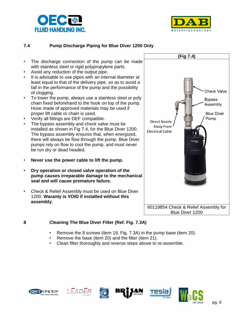
7.4 Pump Discharge Piping for Blue Diver 1200 Only
• The discharge connection of the pump can be made
with stainless steel or rigid polypropylene parts. • Avoid any reduction of the output pipe. • It is advisable to use pipes with an internal diameter at
least equal to that of the delivery pipe, so as to avoid a fall in the performance of the pump and the possibility of clogging.
• To lower the pump, always use a stainless steel or poly chain fixed beforehand to the hook on top of the pump. Hose made of approved materials may be used if proper lift cable or chain is used.
• Verify all fittings are DEF compatible. • The bypass assembly and check valve must be
installed as shown in Fig 7.4, for the Blue Diver 1200. The bypass assembly ensures that, when energized, there will always be flow through the pump. Blue Diver pumps rely on flow to cool the pump, and must never be run dry or dead headed.
• Never use the power cable to lift the pump.
• Dry operation or closed valve operation of the
pump causes irreparable damage to the mechanical seal and will cause premature failure.
• Check & Relief Assembly must be used on Blue Diver
1200. Waranty is VOID if installed without this assembly.
(Fig 7.4)
60119854 Check & Relief Assembly for Blue Diver 1200
8 Cleaning The Blue Diver Filter (Ref. Fig. 7.3A) • Remove the 8 screws (item 19, Fig. 7.3A) in the pump base (item 20). • Remove the base (item 20) and the filter (item 21). • Clean filter thoroughly and reverse steps above to re-assemble.

pg. 10
9 Electrical Connection
Caution! Always follow the safety regulations.
9.1 Electrical Warnings
All electrical work should be performed by a qualified electrician in accordance with the latest edition of the National Electrical Code, local codes and regulations.
Ensure that the mains voltage is the same as the value shown on the motor plate. A faulty motor or winding can cause electrical shock that could be fatal, whether touched directly or conducted through standing water. For this reason, proper grounding of the pump to the power supply’s grounding terminal is required for safe installations, the above-ground metal plumbing should be connected to the power supply as a ground as described in Article 250-80 of the National Electrical Code or Section 26-954 of the Canadian.
9.2 Single Phase Wiring Diagram
Connect the cable of the single phase pump to the electric panel, ensuring that the following parts correspond:
9.3 Electrical Connection Requirements • Blue Diver single phase pumps come with a built-in capacitor, for pump starting.
• The pump should be installed with an electric panel guaranteeing the following functions: overload protection, short circuit protection, dry run protection.
• We strongly request the installation of a ground fault interrupter / RCCD-protector, whose current differential operation must not exceed 30mA

pg. 11
10 Start Up
Do not start the pump unless it has been completely submerged in fluid.
Before start up, the pump must be primed. Prime by means of submerging the entire pump in DEF. This ensures that the mechanical seal is well lubricated, and that the pump immediately discharges fluid. Dry operation causes irreparable damage to the mechanical seal.
• Turn the power supply switch upstream from the pump to position I (ON) and wait until the liquid comes out of the delivery pipe.
• If malfunctions are found, disconnect the pump from the power supply, turning the power supply switch to position 0 (OFF) and consult the section on “TROUBLESHOOTING”.
• The pump may be started and stopped manually by means of the isolator switch upstream from the system.
11 Precautions
The pump should not be started more than 30 times in one hour so as not to subject the motor to excessive thermal shock. The suction filter in BLUE DIVER pumps must always be present during pump operation. DANGER OF FROST: When the pump remains inactive for a long time at temperatures of less than 32°F, the pump body must be completely emptied, to prevent possible cracking of the hydraulic components. This operation is advisable even in the event of prolonged inactivity at normal temperature. When starting after long periods of inactivity, the starting-up operations listed above must be repeated.
12 Maintenance & Inspection
In normal operation, the pump does not require any specific maintenance. However, it may be necessary to clean the hydraulic parts when a decrease in performance is observed. The pump must not be dismantled unless by skilled personnel in possession of the qualifications required by the regulations in force. In any case, all repairs and maintenance jobs must be carried out only after having disconnected the pump from the power mains.
13 Modifications & Spare Parts
Any modification not authorized beforehand relieves the manufacturer of all responsibility. All the spare parts used in repairs must be original ones and the accessories must be approved by the manufacturer so as to be able to guarantee maximum safety of the machines and systems in which they may be fitted.
13.1 Removal and replacement of parts
Before beginning any servicing, ensure that the pump is not connected to the power supply.

pg. 12
14 Troubleshooting
Before taking any troubleshooting action, disconnect the pump from the power supply. If there is any damage to the power cable or pump, all necessary repairs or replacements must be performed by the manufacturer or his authorized customer support service or an equally qualified party with the manufacturer’s permission.
FAULT CHECKS (possible cause) REMEDY
1. The motor does not start and makes no noise.
A. Check the electric connections. B. Check that the motor is live and that the
mains voltage corresponds to the voltage on the data plate.
C. Check the protection fuses.
C. If they are burnt-out, change them. N.B. If the fault is repeated
immediately this means that the motor is short
circuiting.
2. The pump does not deliver.
A. The suction filter or the pipes are blocked. B. The impellers are worn or blocked. C. The check valve, if installed on the delivery pipe, is blocked in closed position. D. The fluid level is too low. On starting, the water level must be higher than the filter level. E. The head required is higher than the pump’s characteristics.
A. Remove the obstructions, as indicated in the chapter on Warnings (Paragraph 6.4.). B. Change the impellers or remove the obstruction. C. Check good operation of the valve and replace it if necessary.
3. The motor turns with difficulty.
A. Check the voltage which may be insufficient.
B. Check whether any moving parts are scraping against fixed parts.
B. See Section 7.3
4. The pump does not deliver.
A. Check that the suction filter is not partially clogged in PULSAR pumps.
B. Ensure that the impellers or the delivery pipe are not partly blocked or fouled with scale. C. Ensure that the impellers are not worn. D. Ensure that the check valve (if fitted) is not partly clogged.
A. Remove any obstructions, as indicated in the chapter on Warnings (Paragraph 6.5.). B. Remove any obstructions. C. Change the impellers. D. Accurately clean the check valve.
5. The overload protection device stops the pump.
A. Ensure that the fluid to be pumped is not too dense because it would cause overheating of the motor. B. Ensure that the water temperature is not too high (see liquid temperature range). C. The pump is partly blocked by impurities. D. The pump is mechanically blocked.
C. Accurately clean the pump. D. Check for the occurrence of rubbing between moving and fixed parts;

pg. 13
15 Parts Listing
Description Part Number
Blue Diver Model 750 60119844
Blue Diver Model 1000 60119849
Blue Diver Model 1200 60119850
Bypass Assembly with Check Valve (for Blue Diver 1200 Only) 60119854
Check Valve, 1-1/2” NPT SS CVSE150
Contact OEC Fluid Handling, Inc. for current pricing and availability (1-800-500-9311).
16 Warranty
DAB Water Technologies will provide a warranty to the original purchaser of the product. A valid warranty will fall within the warranty period shown below.
Product Warranty Period
DEF (Diesel Exhaust Fluid) Handling Systems Products:
DAB Jet Inox SS 50 115/230v 60Hz. Product is warranted 18 months from date of installation, or 24 months from date of manufacture.
Leader US Bluediver 115v 60 Hz. Product is warranted 18 months from date of installation, or 24 months from date of manufacture.
Our Warranty will not apply to any product that; in our sole judgment, has been subject to negligence, misapplication, improper installation, or improper maintenance.
Any material defects will be corrected during the warranty period established by this Limited Warranty. It is up to the manufacturer to decide whether to repair or replace the faulty pump(s).
The manufacturer’s warranty covers all substantial defects attributable to manufacturing or material defects, providing the product has been used correctly and in compliance with the instructions.
The warranty becomes null and void in the event of the following:
Unauthorized attempts to repair the pump.
Unauthorized technical changes to the pump.
Use of non-original spare parts.
Mishandling
For any action or questions concerning your warranty, you can contact OEC Fluid Handling, Inc. at 1-800-500-9311.

pg. 14