installation series dc inverter service manual 48 installation 1 indoor unit installation 1.1...
TRANSCRIPT

U-Match Series DC Inverter Service Manual
47
INSTALLATION

U-Match Series DC Inverter Service Manual
48
INSTALLATION
1 INDOOR UNIT INSTALLATION 1.1 Installation of Duct Type 1.1.1 Before Installation
After receiving the machine, please check for any transport damage. If finding any surface or internal
damage, please immediately report to the transport company or equipment company in writing.
After receiving the machine, please check the unit and accessories in reference to the packing list.
Ensure that the model is correct and the machine is in good condition. Please also check if the specification
and quantity of accessory parts are correct.
Determine the correct handling route and methods, thus to avoid damaging the unit or causing
possible hazard. For the sake of protection and safety, it is suggested to move the unit with the packaging
box. Even though it is not permitted to do like this under special occasions, do not remove the packaging
box, thus to avoid loosening or falling during handling.
Confirm if the installing foundation is solid. When this unit is to be installed on the metal section of the
building, make sure that the electrical insulation must comply with applicable standards.
Ensure that the place of installation is far from the area where the inflammable or explosive
substances are stored, thus to avoid possible explosion or fire due to leakage.
1.1.2 Installation Site
Ensure the top hanging piece has strong strength to withstand the weight of the unit.
The drainage pipe has convenient flow of water.
There is no obstacle blocking the return air inlet and exhaust outlet, so as to ensure sound air
circulation.
The installation spaces required by the drawing must be ensured, so as to provide enough space for
the service and maintenance.
The installation site must be far away from heat source, leakage of inflammable gas or smoke.
The indoor unit is of ceiling mount (indoor unit is hidden inside the ceiling).
The indoor and outdoor units, the power cable and the connecting electrical lines must be at least 1
meter from any TV set or radio. This is to avoid image interference or noise of the TV set or radio. (Even if
the distance is 1 meter, noise can also exist if there is strong electric wave.)
1.1.3 Caution for Installation
Generally, the unit is installed indoor on ceiling. For ceiling mounting, ensure that the hangers on
ceiling have adequate strength to support the weight of the unit.
To meet the noise and vibration requirements, the unit shall be installed by using rubber pad (thickness
≥20mm) and rubber connector.
Insert a M10 expansion bolt into the hole. Drive a nail into the bolt. Refer to the profile dimensions
drawing of the indoor unit for the distance between the holes. Refer to Figure 3-1-1 for the installation of the
expansion bolt.

U-Match Series DC Inverter Service Manual
49
Ceiling-mount
Screw
Air-conditioning Unit
Hanger
Figure 3-1-1 Figure 3-1-2
Hook Screw
Nut
Nut
Figure 3-1-3
Install the hanger onto the indoor unit as Figure 3-1-2 and Figure 3-1-3 shows.
Install the indoor unit at the ceiling as Figure Figure 3-1-4 shows.
I
Air Intake Air Supply
Screw
Hanger
Nut≤4
8m
m(1
-7/8
inch)
I Detail
Figure 3-1-4
Precautions for unfavorable installation:
The preparation of all pipes (connecting pipes and drainage pipes) and cables (connecting lines of
wire controller, indoor unit and outdoor unit) must be ready before the installation, so as to achieve smooth
installation.
Drill an opening on the ceiling. Maybe it is required to support the ceiling to ensure the evenness of it
and avoid the vibration of it. Consult with the user or a construction company for details.
In case the strength of ceiling is not enough, use angle iron sections to set up a beam support. Place
the unit at the beam and fix it.
Level inspection of the indoor unit
After the indoor unit is installed, it is required to check the level of the whole unit. The unit must be
placed horizontally, but the condensate pipe shall be installed obliquely, so as to facilitate the drainage of
condensate.

U-Match Series DC Inverter Service Manual
50
Condensate
Drainpipes
Level Instrument
Air Intake Air Supply
B
A
B
Enlarged View
Condensate Drainpipe
As the inside of the unit is in the negative
pressure status, it is required to set up a
backwater elbow. The requirements is:
A=B≥(0.145P/10000+20)/25.4(inch)
P is the absolute pressure inside the unit.
The unit of the pressure is psig.
Figure 3-1-5
1.1.4 Dimension Data
For the units: GFH24S3GI、GFH24S3G1I
E
Max
A
C
D
B F
Max
G
I H J
Gas Pipe Liquid Pipe
Air Intake
Drainage Pipe Electric Box
For the units: GFH36S3GI,GFH36S3G1I,GFH42S3GI,GFH42S3G1I,GFH48S3GI,GFH48S3G1I
A
B
C
DE
F
G
H IJ
Figure 3-1-6

U-Match Series DC Inverter Service Manual
51
For the units: GFH60S3GI,GFH60S3G1I
Table 3-1-1
Item
Model A B C D E F G H I J
GFH24S3GI
GFH24S3G1I 1011 748 820 1115 1225 775 978 160 230 290
GFH36S3GI
GFH36S3G1I
1175 646 852 1150 1340 750 953 190 316 350 GFH42S3GI
GFH42S3G1I
GFH48S3GI
GFH48S3G1I
GFH60S3GI
GFH60S3G1I 1353 632 992 1150 192 340 1500 390 800 --
Table 3-1-2 Installation Accessories List for Duct-type Indoor Unit
Name & Shape QTY Notes
Installation and Operating
Instructions 1
Insulation materials for gas pipe 1 Used for gas pipe connector on indoor unit.
Insulation materials for liquid
pipe 1 Used for liquid pipe connector on indoor unit.
Insulation materials for drainage
pipe 2
Used for wrapping the condensate pipe and
rubber plug.
Nut 1 To connect liquid pipe.
Nut 1 To connect gas pipe.
Nut M6 with gasket 8 Use for fixing the hanger hook.
Nut M10 with gasket 4 Use for fixing the hanger hook.
Nut M10 4 4 sets, used for ceiling mounting of the indoor
unit. spring gasket 4
Hook 4 Used for ceiling mounting of the indoor unit.
Wired controller 1
Screw M4 2 To fix the base plate of wired controller and
installation hole of the wall together.

U-Match Series DC Inverter Service Manual
52
1.1.5 Installation Clearance Data
>2500m
m
(98-3
/8in
ch)
Nut with
WasherNut Spring
Washer
>250mm
(9-7/8inch) >250mm
(9-7/8inch)
Figure 3-1-7
Warning: The height of installation for the indoor unit should be 2.5m above.
1.1.6 Drain Piping Work
Installation of Drainage Pipeline:
CAUTION!
Install the drain hose in accordance with the instructions in this installation manual and keep the
area warm enough to prevent condensation. Problems with the piping may lead to water leaks.
(1) Install the drain hose with downward gradient (1/50 to 1/100) and no risers or traps are used for
the hose.( Figure 3-1-8)
(2) Be sure there is no crack or leak on the drain hose to avoid the formation of air pocket.( Figure
3-1-8)
(3) When the hose is long, install supporters.( Figure 3-1-9)
(4) Always use the drain hose which has been insulated properly.
Drain hose
Arrange the drain hose
lower than this drain port
Trap
Air bleedingRise
√
Figure 3-1-8
Supporter
Drain hose1~1.5m(3-2/7~5feet)
Figure 3-1-9 Figure 3-1-10

U-Match Series DC Inverter Service Manual
53
Condensate Drainpipe
B
A
As the inside of the unit is in the
negative pressure status, it is required
to set up a backwater elbow. The
requirements is:
A=B≥(0.145P/10000+20)/25.4(inch)
P is the absolute pressure inside the
unit. The unit of the pressure is psig.
Condensate Drainpipe
Enlarged View
B
A
Figure 3-1-11
(5) Use a suitable drain hose, and see Table 3-2-4 for its size.
(6) There is a drain port on both the left and right sides. Select the drain port to match the local
conditions.( Figure 3-1-10)
(7) When the unit is shipped from the factory, the drain port is defaulted to be the one on the left side
(electric box side), the port on right side has been plugged.
(8) When using the drain port on the right side of the unit, reinstall the drain cap to the left side drain
port.( Figure 3-1-12)
Drain port
Fastener
Drain cap
Figure 3-1-12
CAUTION!
Always check that the drain cap is installed to the unused drain port and is fastened with the
nylon fastener. If the drain cap is not installed, or is not sufficiently fastened by the nylon
fastener, water may drip during the cooling operation.
(9) Be sure to insulate where the drain port and the drain hose is connected.( Figure 3-1-13 )
(10) The unused drain port also should be insulated properly.( Figure 3-1-14)

U-Match Series DC Inverter Service Manual
54
Drain hose insulation
Drain port
Insulated drain hose
Insulated drain hose
Unit
0mm(0inch)
Drain hose insulation
Drain port
Drain cap
0mm(0inch)
Unit
Drain cap
Figure 3-1-13 Figure 3-1-14 There is adhesive on one side of the insulation so that after removing the protective paper over it the insulation can be directly attached to the drain hose.
(11) Considerations for the unit with the condensate pump:
1) For the unit with the condensate pump, only one drain port at the side close to the electric box
is prepared and only through it the drain hose can be connected.
2) See table 3 for the size of the drain port of the unit with the condensate pump, which is different
from that of the unit without the condensate pump.
3) For the unit with the condensate pump, two drain ports at the bottom are defaulted to be factory
plugged with drain caps. After the installation of the drain hose, these two drain ports also need
to be insulated properly with the same way aforementioned.
4) The drain hose for the unit with the condensate pump should be arranged as shown in the
figure below.
Ceiling
Hoisting stand
Clamp(attachment)
Drain hose(attachment)
Drain raising
hose
≤300mm(11-3/4inch)1000~1500mm(39-3/8~59inch)
≤10
0m
m
(39-3
/8in
ch
)
Figure 3-1-15
a) The vertical height of the drain hose should be 75mm or less so that it is unnecessary for the
drain port to withstand additional force.
Drain hose(attachment)
≤75
mm
(3in
ch
)
≤10
00
mm
(39-3
/8in
ch)
Figure 3-1-16
b) When multiple drain hoses are used, their installation should be performed as shown in the
figure below.

U-Match Series DC Inverter Service Manual
55
0~
1000m
m(0
~39-3
/8in
ch)
≥100m
m(3
-7/8
inch)
T-joint converging drain pipes
T-joint converging drain pipes
Figure 3-1-17
1.1.7 Installation of air duct
Dimensions of the Supply Air Outlet/Return Air Inlet
B
A
21mm(7/8inch)
Figure 3-1-18 Supply Air Outlet
C
D
Figure 3-1-19 Return Air Inlet
Table 3-1-3
Item
Model
Supply Air Outlet Return Air Inlet
A B C D
GFH24S3GI
GFH24S3G1I 158 818 950 206
GFH36S3GI
GFH36S3G1I 190 850 941 286
GFH42S3GI
GFH42S3G1I 190 850 941 286
GFH48S3GI
GFH48S3G1I 190 850 941 286
GFH60S3GI
GFH60S3G1I 190 990 1108 288

U-Match Series DC Inverter Service Manual
56
1.1.8 Installation of the Supply Air Duct
(1) Installation of the Rectangular Duct.
No. Name No. Name
1 Hanger 5 Filter
2 Air Intake Pipe 6 Main Air Supply
Pipe
3 Canvas Air Pipe 7 Air Supply Outlet
4 Air Intake
Figure 3-1-20
CAUTION!
①. The maximum length of the duct means the maximum length of the supply air duct plus the
maximum length of the return air duct.
②. The duct is rectangular and connected with the air inlet/outlet of the indoor unit. Among all
supply air outlets, at least one should be kept open.
(2) The default installation location of the rectangular flange is at the back and the return air cover
plate is at the bottom, as shown in Figure 3-1-21 .
Rear Return Air
Rectangular Flange
Figure 3-1-21
(3) If the bottom return air is desired, just change the place of the rectangular flange and the return air
cover plate.
(4) Connect one end of the return air duct to the return air outlet of the unit by rivets and the other to
the return air louver. For the sake of the convenience to freely adjust the height, a cutting of
canvas duct will be helpful, which can be reinforced and folded by 8# iron wire
(5) More noise is likely to be produced in the bottom return air mode than the backward return air
mode, so it is suggested to install a silencer and a static pressure box to minimize the noise.
(6) The installation method can be chosen with considering the conditions of the building and
maintenance etc., as shown in Figure 3-1-22.

U-Match Series DC Inverter Service Manual
57
Supply air
Return air
Install the return air duct(b)
5
4 2
3
1
Figure 3-1-22
Table 3-1-4 Installation of the return air duct
No. Name No. Name
1 Return Air Inlet
(with filter) 4 Indoor unit
2 Grille 5 Supply Air Duct
3 Return Air Duct
2 OUTDOOR UNIT INSTALLATION 2.1 Before Installation
After receiving the machine, please check for any transport damage. If finding any surface or internal
damage, please immediately report to the transport company or equipment company in writing.
After receiving the machine, please check the unit and accessories in reference to the packing list.
Ensure that the model is correct and the machine is in good condition. Please also check if the specification
and quantity of accessory parts are correct.
Determine the correct handling route and methods, thus to avoid damaging the unit or causing
possible hazard. For the sake of protection and safety, it is suggested to move the unit with the packaging
box. Even though it is not permitted to do like this under special occasions, do not remove the packaging
box, thus to avoid loosening or falling during handling.
Confirm if the installing foundation is solid. When this unit is to be installed on the metal section of the
building, make sure that the electrical insulation must comply with applicable standards.
Ensure that the place of installation is far from the area where the inflammable or explosive
substances are stored, thus to avoid possible explosion or fire due to leakage.
2.2 Installation Site
①. Install the unit where it will not be tilted by more than 5°.
②. During installation, if the outdoor unit has to be exposed to strong wind, it must be fixed securely.
If possible, do not install the unit where it will be exposed to direct sunlight. (If necessary, install a blind
that does not interfere with the air flow.)
(1) Install the outdoor unit in a place where it will be free from being dirty or getting wet by rain as
much as possible.
(2) Install the outdoor unit where it is convenient to connect with the indoor unit.
(3) Install the outdoor unit where the condensate water can be drained out freely during heating

U-Match Series DC Inverter Service Manual
58
operation.
(4) Do not place animals and plants in the path of the warm air.
(5) Take the air conditioner weight into account and select a place where noise and vibration are
small.
(6) Install the outdoor unit where is capable of withstanding the weight of the unit and generates as
less noise and vibration as possible.
(7) Provide the space shown in Figure 3-2-1, so that the air flow is not blocked. Also for efficient
operation, leave three of four directions of peripheral constructions open.
>500m
m(1
-2/3
feet)
>2000m
m(6
-5/9
feet)
>500m
m(1
-2/3
feet)
>500m
m(1
-2/3
feet)
>500mm(1-2/3feet)
>2000mm(6-5/9feet) >
1000m
m(3
-2/7
feet)
Figure 3-2-1
2.3 Caution for Installation
The outdoor unit shall be so installed that the air discharged out of the outdoor unit will not flow back
and that enough space shall be maintained around the machine for repair;
The installing position shall be in good ventilation, so that the machine can breathe and exhaust
enough air. Ensure that there is no obstruction at the inlet and outlet of the machine. If any, please remove
the obstructions blocking the air inlet and outlet.
If the outdoor unit is installed on concrete or solid ground, it shall be fixed by using M10 bolts and nuts.
And ensure that the machine is kept vertical and horizontal.
The outdoor unit must be lifted by using the designated lift hole. During lifting, take care to protect the
air conditioner and avoid knocking the metal parts, thus to prevent rusting in the future.
To meet the noise and vibration requirements, the outdoor unit shall be installed by using rubber
damping pad or spring damper.
To install the drainage pipe, please insert the drainage joint to the drainage hole on the outdoor
chassis and connect a drainage pipe on the drainage joint. (The installing height of outdoor unit shall be at
least 5cm if drainage joint is to be used).
To insert the pipe through the wall, the wall-cross tube must be installed.
The installing dimension shall comply with the installation requirements in these instructions. The
outdoor unit must be fixed at the installing position.
The installation shall be done by specialist technicians.

U-Match Series DC Inverter Service Manual
59
2.4 Dimension Data
D
A
B
C
E
Figure 3-2-2
Table 3-2-1 Unit: mm
Item
Model A B C D E
GUHD24NS3GO 1005 425 790 610 391
GUHD36NS3GO 1105 440 1105 631 401
GUHD42NS3GO
GUHD48NS3GO 1085 425 1365 620 393
GUHD60NS3GO
3 REFRIGERATION PIPING WORK 3.1 Refrigeration Piping Work Procedures and Caution in Connecting 3.1.1 Flare Processing
(1) Cut the connection pipe with the pipe cutter and remove the burrs.
(2) Hold the pipe downward to prevent cuttings from entering the pipe.
(3) Remove the flare nuts at the stop valve of the outdoor unit and inside the accessory bag of the
indoor unit, then insert them to the connection pipe, after that, flare the connection pipe with a
flaring tool.
(4) Check if the flare part is spread evenly and there are no cracks (see Figure 3-2-3).
d2
d1
d1
d2
90°±1°
Figure 3-2-3

U-Match Series DC Inverter Service Manual
60
3.1.2 Bending Pipes
(1) The pipes are shaped by your hands. Be careful not to collapse them.
Extend the pipe by unwinding it
√ ×
Figure 3-2-4
(2) Do not bend the pipes in an angle more than 90°.
(3) When pipes are repeatedly bent or stretched, the material will harden, making it difficult to bend or
stretch them any more. Do not bend or stretch the pipes more than three times.
(4) When bending the pipe, do not bend it as is. The pipe will be collapsed. In this case, cut the heat
insulating pipe with a sharp cutter as shown in Figure 3-2-5, and bend it after exposing the pipe.
After bending the pipe as you want, be sure to put the heat insulating pipe back on the pipe, and
secure it with tape.
Pipe
Cutter
Cutt line
Heat insulating
pipe
Figure 3-2-5
To prevent breaking of the pipe, avoid sharp bends. Bend the pipe with a radius of curvature of 150mm or over.
If the pipe is bent repeatedly at the same place, it will break.
3.1.3 Connecting the Pipe at the Indoor Unit Side
Detach the caps and plugs from the pipes.
①. Be sure to apply the pipe against the port on the indoor unit correctly. If the centering is improper, the flare nut
cannot be tightened smoothly. If the flare nut is forced to turn, the threads will be damaged.
②. Do not remove the flare nut until the connection pipe is to be connected so as to prevent dust and impurities from
coming into the pipe system.
When connecting the pipe to the unit or removing it from the unit, please do use both the spanner and
the torque wrench.( Figure 3-2-6)
When connecting, smear both inside and outside of the flare nut with refrigeration oil, screw it hand
tight and then tighten it with the spanner.
Refer to Table 10 to check if the wrench has been tightened properly (too tight would mangle the nut
and lead to leakage).
Examine the connection pipe to see if it leaks, then take the treatment of heat insulation, as shown in
the Figure 3-2-6.
Use the medium-sized sponge to insulate the coupler of the gas pipe.

U-Match Series DC Inverter Service Manual
61
Sponge
Threaded fastener(×4)
Liquid pipe
Gas inlet pipe
Heat insulation sheath
(for the gas tube)
Heat insulation sheath
(for the liquid tube)
Figure 3-2-6
Table 3-2-2 Flare nut tightening torque
Pipe Diameter Tightening Torque
1/4〞(Inch) 15-30 (N·m)
3/8〞(Inch) 35-40 (N·m)
5/8〞(Inch) 60-65 (N·m)
1/2〞(Inch) 45-50 (N·m)
3/4〞(Inch) 70-75 (N·m)
7/8〞(Inch) 80-85 (N·m)
Cautions
Be sure to connect the gas pipe after connecting the liquid pipe completely.
3.1.4 Connecting the Pipe at the Outdoor Side Unit
Tighten the flare nut of the connection pipe at the outdoor unit valve connector. The tightening method
is the same as that as at the indoor side.
3.1.5 Checking the Pipe Connections for Gas Leaking
For both indoor and outdoor unit side, check the joints for gas
leaking by the use of a gas leakage detector without fail when the
pipes are connected. Gas pipe Liquid pipe
Pipe
couplingor
or
3-way valve 2-way valve
Figure 3-2-2
U-Match Series DC Inverter Service Manual
62
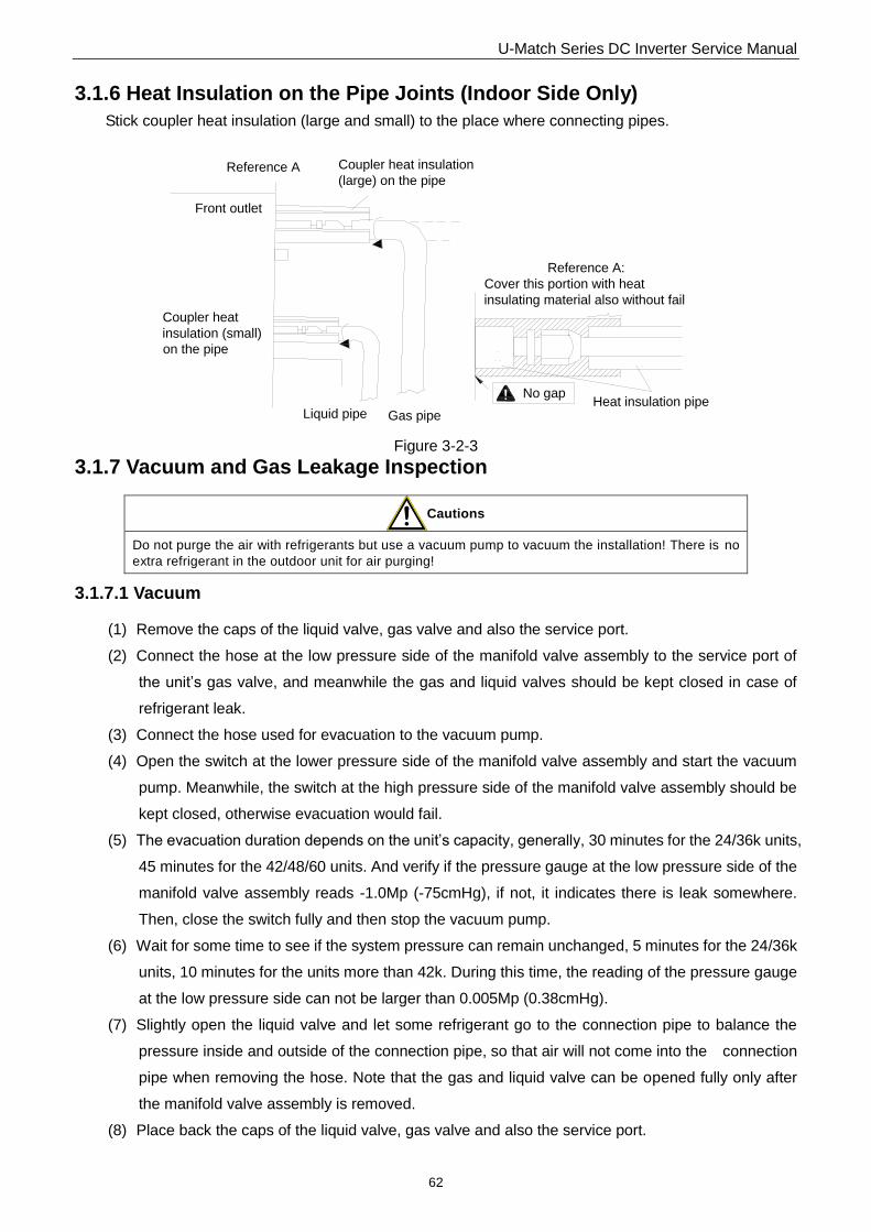
3.1.6 Heat Insulation on the Pipe Joints (Indoor Side Only)
Stick coupler heat insulation (large and small) to the place where connecting pipes.
Front outlet
Coupler heat
insulation (small)
on the pipe
Liquid pipe Gas pipe
Reference A Coupler heat insulation
(large) on the pipe
Heat insulation pipe
Reference A:
Cover this portion with heat
insulating material also without fail
No gap
Figure 3-2-3
3.1.7 Vacuum and Gas Leakage Inspection
Cautions
Do not purge the air with refrigerants but use a vacuum pump to vacuum the installation! There is no
extra refrigerant in the outdoor unit for air purging!
3.1.7.1 Vacuum
(1) Remove the caps of the liquid valve, gas valve and also the service port.
(2) Connect the hose at the low pressure side of the manifold valve assembly to the service port of
the unit‟s gas valve, and meanwhile the gas and liquid valves should be kept closed in case of
refrigerant leak.
(3) Connect the hose used for evacuation to the vacuum pump.
(4) Open the switch at the lower pressure side of the manifold valve assembly and start the vacuum
pump. Meanwhile, the switch at the high pressure side of the manifold valve assembly should be
kept closed, otherwise evacuation would fail.
(5) The evacuation duration depends on the unit‟s capacity, generally, 30 minutes for the 24/36k units,
45 minutes for the 42/48/60 units. And verify if the pressure gauge at the low pressure side of the
manifold valve assembly reads -1.0Mp (-75cmHg), if not, it indicates there is leak somewhere.
Then, close the switch fully and then stop the vacuum pump.
(6) Wait for some time to see if the system pressure can remain unchanged, 5 minutes for the 24/36k
units, 10 minutes for the units more than 42k. During this time, the reading of the pressure gauge
at the low pressure side can not be larger than 0.005Mp (0.38cmHg).
(7) Slightly open the liquid valve and let some refrigerant go to the connection pipe to balance the
pressure inside and outside of the connection pipe, so that air will not come into the connection
pipe when removing the hose. Note that the gas and liquid valve can be opened fully only after
the manifold valve assembly is removed.
(8) Place back the caps of the liquid valve, gas valve and also the service port.
U-Match Series DC Inverter Service Manual
63
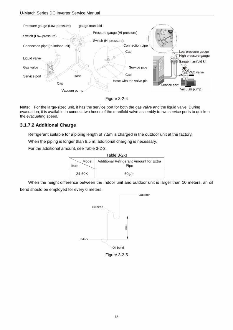
Hose with the valve pin
gauge manifoldPressure gauge (Low-pressure)
Pressure gauge (Hi-pressure)Switch (Low-pressure)
Switch (Hi-pressure)
Connection pipe (to indoor unit)
Liquid valve
Gas valve
Service port
Cap
Hose
Vacuum pump
Cap
Service pipe
Cap
Connection pipe
Figure 3-2-4
Note: For the large-sized unit, it has the service port for both the gas valve and the liquid valve. During evacuation, it is available to connect two hoses of the manifold valve assembly to two service ports to quicken the evacuating speed.
3.1.7.2 Additional Charge
Refrigerant suitable for a piping length of 7.5m is charged in the outdoor unit at the factory.
When the piping is longer than 9.5 m, additional charging is necessary.
For the additional amount, see Table 3-2-3.
Table 3-2-3
Model
Item
Additional Refrigerant Amount for Extra
Pipe
24-60K 60g/m
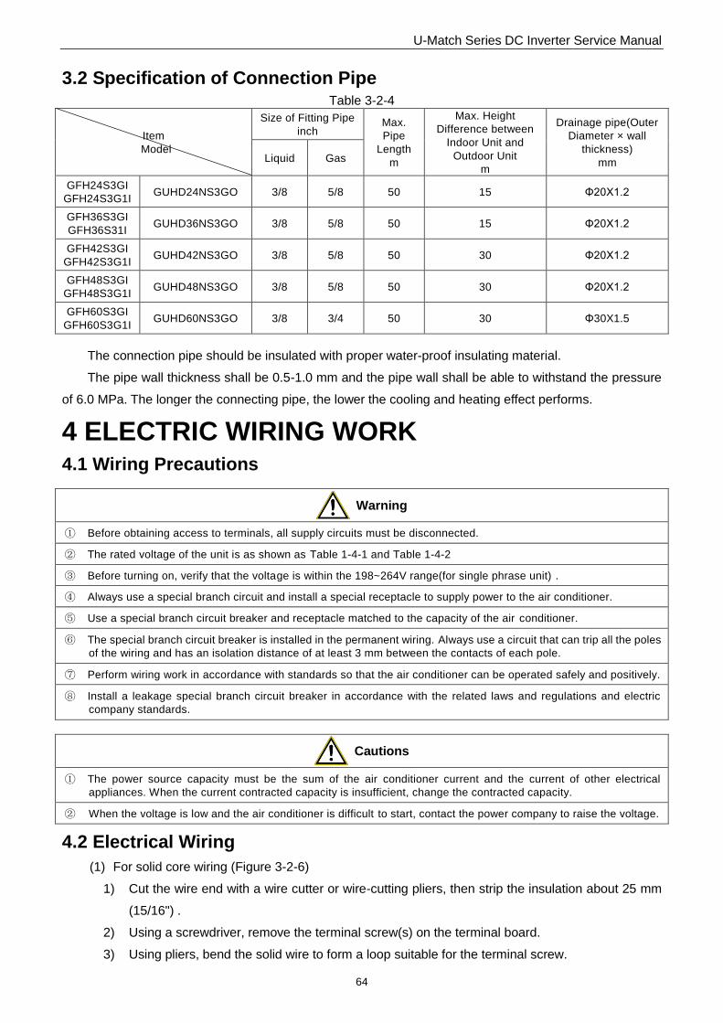
When the height difference between the indoor unit and outdoor unit is larger than 10 meters, an oil
bend should be employed for every 6 meters.
Oil bend
Oil bend
Indoor
Outdoor
6m
Figure 3-2-5
U-Match Series DC Inverter Service Manual
64
3.2 Specification of Connection Pipe Table 3-2-4
Item
Model
Size of Fitting Pipe
inch Max.
Pipe
Length
m
Max. Height
Difference between
Indoor Unit and
Outdoor Unit
m
Drainage pipe(Outer
Diameter × wall
thickness)
mm Liquid Gas
GFH24S3GI
GFH24S3G1I GUHD24NS3GO 3/8 5/8 50 15 Φ20X1.2
GFH36S3GI
GFH36S31I GUHD36NS3GO 3/8 5/8 50 15 Φ20X1.2
GFH42S3GI
GFH42S3G1I GUHD42NS3GO 3/8 5/8 50 30 Φ20X1.2
GFH48S3GI
GFH48S3G1I GUHD48NS3GO 3/8 5/8 50 30 Φ20X1.2
GFH60S3GI
GFH60S3G1I GUHD60NS3GO 3/8 3/4 50 30 Φ30X1.5
The connection pipe should be insulated with proper water-proof insulating material.
The pipe wall thickness shall be 0.5-1.0 mm and the pipe wall shall be able to withstand the pressure
of 6.0 MPa. The longer the connecting pipe, the lower the cooling and heating effect performs.
4 ELECTRIC WIRING WORK
4.1 Wiring Precautions
Warning
① Before obtaining access to terminals, all supply circuits must be disconnected.
② The rated voltage of the unit is as shown as Table 1-4-1 and Table 1-4-2
③ Before turning on, verify that the voltage is within the 198~264V range(for single phrase unit) .
④ Always use a special branch circuit and install a special receptacle to supply power to the air conditioner.
⑤ Use a special branch circuit breaker and receptacle matched to the capacity of the air conditioner.
⑥ The special branch circuit breaker is installed in the permanent wiring. Always use a circuit that can trip all the poles
of the wiring and has an isolation distance of at least 3 mm between the contacts of each pole.
⑦ Perform wiring work in accordance with standards so that the air conditioner can be operated safely and positively.
⑧ Install a leakage special branch circuit breaker in accordance with the related laws and regulations and electric
company standards.
Cautions
① The power source capacity must be the sum of the air conditioner current and the current of other electrical
appliances. When the current contracted capacity is insufficient, change the contracted capacity.
② When the voltage is low and the air conditioner is difficult to start, contact the power company to raise the voltage.
4.2 Electrical Wiring
(1) For solid core wiring (Figure 3-2-6)
1) Cut the wire end with a wire cutter or wire-cutting pliers, then strip the insulation about 25 mm
(15/16") .
2) Using a screwdriver, remove the terminal screw(s) on the terminal board.
3) Using pliers, bend the solid wire to form a loop suitable for the terminal screw.

U-Match Series DC Inverter Service Manual
65
4) Shape the loop wire properly, place it on the terminal board and tighten securely with the
terminal screw using a screwdriver.
(2) For strand wiring (Figure 3-2-6)
1) Cut the wire end with a wire cutter or wire-cutting pliers, then strip the insulation about 10 mm
(3/8") .
2) Using a screwdriver, remove the terminal screw (s) on the terminal board.
3) Using a round terminal fastener or pliers, securely clamp a round terminal to each stripped wire
end.
4) Position the round terminal wire, and replace and tighten the terminal screw with a
screwdriver.( Figure 3-2-7)
10m
m(3
/8in
ch)
A Solid wire B Strand wire
Solderless
terminal
Insulation layer
25m
m(1
inch)
Figure 3-2-6
Screw with
special washer
Round
terminal
Terminal
board
Screw with
special washer
Round
terminal
Wire
Wire
Insulation tube
Insulation tube
Cord clamp
Figure 3-2-7 Figure 3-2-8
(3) How to fix connection cord and power cord by cord clamp
After passing the connection cord and power cord through the insulation tube, fasten it with the cord
clamp.( Figure 3-2-8)
Warning
①. Before starting work, check that power is not being supplied to the indoor unit and outdoor unit.
②. Match the terminal block numbers and connection cord colors with those of the indoor unit side.
③. Erroneous wiring may cause burning of the electric parts.
④. Connect the connection cords firmly to the terminal block. Imperfect installation may cause a fire.
⑤. Always fasten the outside covering of the connection cord with cord clamps. (If the insulator is not clamped, electric
leakage may occur.)
⑥. Always connect the ground wire.

U-Match Series DC Inverter Service Manual
66
(4) Electric wiring between the indoor and outdoor units Single-phase units
1) Separate Power Supply for indoor unit and outdoor unit:
Outdoor Unit Indoor Unit
1 1
L1
2 2
N1
L N PE
Breaker
Power:220-240V~50/60Hz
L N PE
Breaker
Power:220-240V~50/60Hz
L N F C OL2N2
3
1 2
24k-60k
GUHD24NS3GO+GFH24S3GI/GFH24S3G1I
①. Power cord 3×2.5mm2(H07RN-F)
②. Power cord 3×1.0mm2(H05RN-F)
③. Communication Cords 2×0.75mm2(H05RN-F)
GUHD36NS3GO+GFH36S3GI/GFH36S3G1I
GUHD42NS3GO+GFH42S3GI/GFH42S3G1I
①. Power cord 3×4.0mm2(H07RN-F)
②. Power cord 3×1.0mm2(H05RN-F)
③. Communication Cords 2×0.75mm2(H05RN-F)
GUHD48NS3GO+GFH48S3GI/GFH48S3G1I
GUHD60NS3GO+GFH60S3GI/GFH60S3G1I
①. Power cord 3×6.0mm2(H07RN-F)
②. Power cord 3×1.0mm2(H05RN-F)
③. Communication Cords 2×0.75mm2(H05RN-F)
2) The Power supply for indoor unitis from outdoor unit.
Outdoor Unit Indoor Unit
1 1
L1
2 2
N1
L NPE
Breaker
Power:220-240V~50/60Hz
L N F C OL2 N2
3
2
1
24k-60k
Figure 3-2-9
U-Match Series DC Inverter Service Manual
67
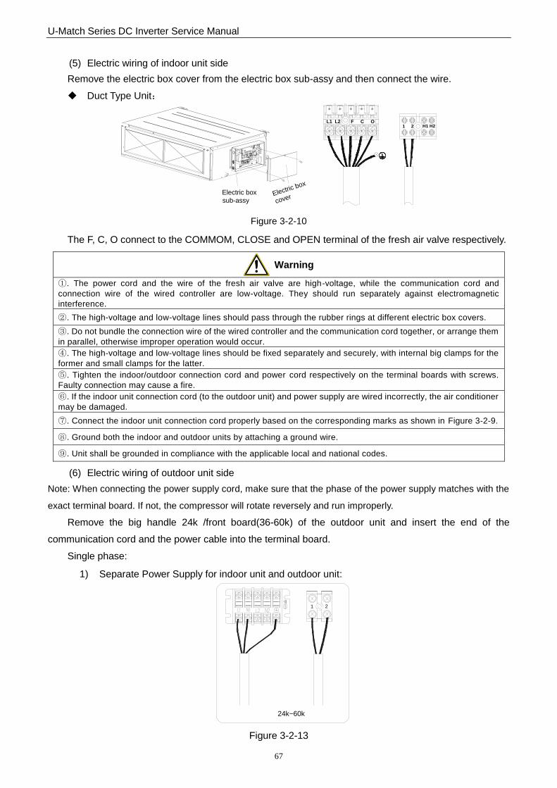
(5) Electric wiring of indoor unit side
Remove the electric box cover from the electric box sub-assy and then connect the wire.
Duct Type Unit:
Electric box
sub-assyElectric box
cover
L1 L2 F C OH1 H21 2
Figure 3-2-10
The F, C, O connect to the COMMOM, CLOSE and OPEN terminal of the fresh air valve respectively.
Warning
①. The power cord and the wire of the fresh air valve are high-voltage, while the communication cord and
connection wire of the wired controller are low-voltage. They should run separately against electromagnetic
interference.
②. The high-voltage and low-voltage lines should pass through the rubber rings at different electric box covers.
③. Do not bundle the connection wire of the wired controller and the communication cord together, or arrange them
in parallel, otherwise improper operation would occur.
④. The high-voltage and low-voltage lines should be fixed separately and securely, with internal big clamps for the
former and small clamps for the latter.
⑤. Tighten the indoor/outdoor connection cord and power cord respectively on the terminal boards with screws.
Faulty connection may cause a fire.
⑥. If the indoor unit connection cord (to the outdoor unit) and power supply are wired incorrectly, the air conditioner
may be damaged.
⑦. Connect the indoor unit connection cord properly based on the corresponding marks as shown in Figure 3-2-9.
⑧. Ground both the indoor and outdoor units by attaching a ground wire.
⑨. Unit shall be grounded in compliance with the applicable local and national codes.
(6) Electric wiring of outdoor unit side
Note: When connecting the power supply cord, make sure that the phase of the power supply matches with the
exact terminal board. If not, the compressor will rotate reversely and run improperly.
Remove the big handle 24k /front board(36-60k) of the outdoor unit and insert the end of the
communication cord and the power cable into the terminal board.
Single phase:
1) Separate Power Supply for indoor unit and outdoor unit:
24k~60k
1 2
Figure 3-2-13
U-Match Series DC Inverter Service Manual
68
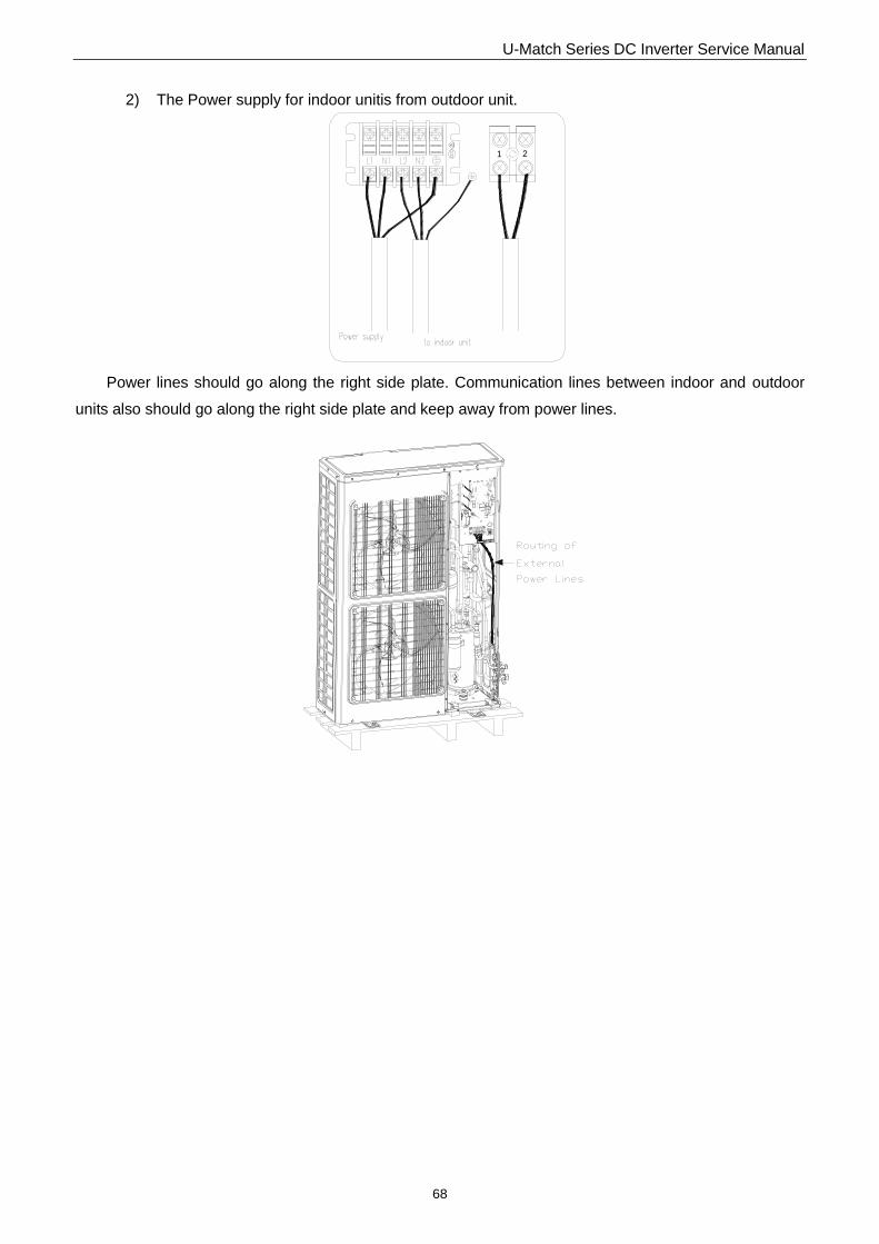
2) The Power supply for indoor unitis from outdoor unit.
1 2
Power lines should go along the right side plate. Communication lines between indoor and outdoor
units also should go along the right side plate and keep away from power lines.