installation & service manual ground level concrete pads - however, mezzanine construction...
TRANSCRIPT

Installation & Service ManualPARALLEL COMPRESSORS
& ENVIROGUARD
June, 2007 Planning for Mezzanine Machine Rooms / 1-1
SS EE CC TT II OO NN 11Planning for Mezzanine Machine Rooms
Many compressor rooms today are installed in mezzanine locations. With conventional systems, the units are typically spring mounted and spread over the expanse of the mezzaninearea. With parallels, the total weight of the assembly may be as high as 7,900#, all concentrated in 54.3 sq. ft. or less. The industry typically uses solid mount compressor mountings for the purpose of simplifying piping to fixed manifolds. This poses no problem with ground level concrete pads - however, mezzanine construction frequently doesn’t considerthis. This can result in normal vibrations, harmonics and pulsations being amplified.
NOTE:It is imperative that the mezzanine floor design provides an adequate mass to keep vibrations, harmonics and pulsations within normal ranges. The floor surface must besmooth and level.Following These Guidelines:
Maximum Weight of Racks*
P67 P90 P120 P140 P160 P180
2 or 3 Compr. 3 or 4 Compr. 4 or 5 Compr. 5 or 6 Compr. 6 or 7 Compr. 7 or 8 Compr.
3,800# 4,400# 5,500# 6,100# 7,000# 7,900#
21 sq. ft. 27.5 sq. ft. 34 sq. ft. 41 sq.ft. 47.5 sq. ft. 54.3 sq. ft.
* Consult factory for all custom rack applications.
Machine Room Ventilation Requirements:
Remote Air: 100CFM/HP Water Cooled: 100 CFM/HP Air Cooled: 1,000 CFM/HP

PARALLEL COMPRESSORS& ENVIROGUARD
1-2 / Planning for Mezzanine Machine Rooms June, 2007
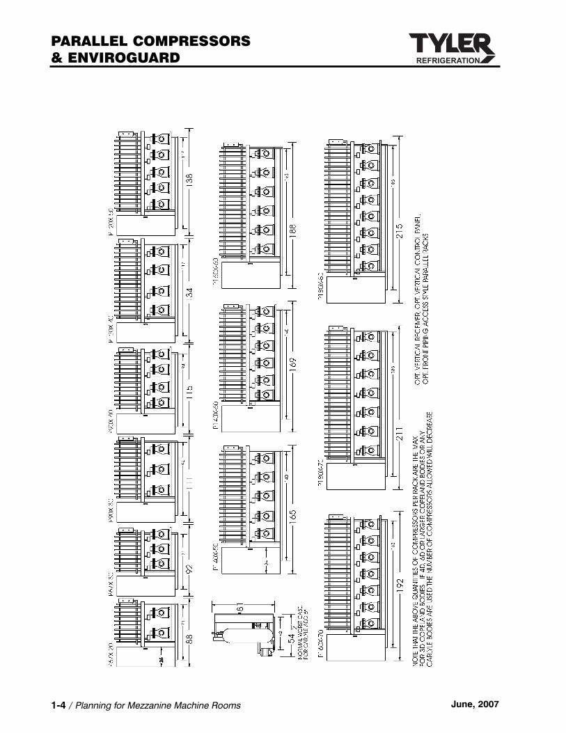
Parallel Compressor Rack Dimensions

Installation & Service ManualPARALLEL COMPRESSORS
& ENVIROGUARD
June, 2007 Planning for Mezzanine Machine Rooms / 1-3
PARALLEL COMPRESSORS& ENVIROGUARD
1-4 / Planning for Mezzanine Machine Rooms June, 2007

Installation & Service ManualPARALLEL COMPRESSORS
& ENVIROGUARD
June, 2007 Planning for Mezzanine Machine Rooms / 1-5
Parallel Compressor Rack ISOL Pad Mounting Drawings

PARALLEL COMPRESSORS& ENVIROGUARD
1-6 / Planning for Mezzanine Machine Rooms June, 2007

Installation & Service ManualPARALLEL COMPRESSORS
& ENVIROGUARD
June, 2007 Planning for Mezzanine Machine Rooms / 1-7
Parallel Compressor Rack ISOL Spring Mounting Drawings

PARALLEL COMPRESSORS& ENVIROGUARD
1-8 / Planning for Mezzanine Machine Rooms June, 2007

Installation & Service ManualPARALLEL COMPRESSORS
& ENVIROGUARD
June, 2007 Planning for Mezzanine Machine Rooms / 1-9

PARALLEL COMPRESSORS& ENVIROGUARD
1-10 / Planning for Mezzanine Machine Rooms June, 2007

Installation & Service ManualPARALLEL COMPRESSORS
& ENVIROGUARD
June, 2007 Planning for Mezzanine Machine Rooms / 1-11
Setting Parallel Racks on Kinetic Absorption Pads
The kinetic absorption pads should be placed in the locations shown. The pads must beinstalled PRIOR to piping installation.
Installation
Install the pads with the identification holes up.
NOTE:PADS WILL NOT LAST IF THEY ARE NOT PROPERLY INSTALLED!
Optional Spring Mounting Pads for Parallel Racks
The optional spring mounts should be placed in the locations shown. The mounts must beinstalled PRIOR to piping installation.
Spring Installation: Install the spring mounts with the long side of the mount parallel with the rail of the compressor rack.
To Level Equipment: Adjust the height of the spring mountings by rotating the 1/2” adjusting bolt. Check to see that the clearance between the upper & lower spring assemblies is at least 1/4”, bu not more than 1/2”.


Installation & Service ManualPARALLEL COMPRESSORS
& ENVIROGUARD
June, 2007 Refrigeration Piping / 2-1
SS EE CC TT II OO NN 22Refrigeration Piping
Successful Installation of a Refrigeration System is Dependent Upon:
1. Good piping practices - with properly sized and installed lines as directed in this section.
2. Cleanliness of all refrigeration piping is of the utmost importance in the installation procedure.
CAUTIONThe use of gaseous nitrogen or carbon dioxide flowing at low pressure through the lines while they are being welded is necessary to assure relative freedom from oxidesand scale which can clog the small ports on pilot operated valves and other valves in this system.
Some Possible Consequences of Poor Piping:
• Increase oil requirements.• Decreased operating efficiency and loss of capacity.• Increased changes of fouling vital components.• Failed compressors.
When NC-2, NC-3 or Enviroguard is employed, ALL LIQUID LINES to and from the parallelrack (all the way from the compressor rack to the fixtures) MUST BE INSULATED! Allowingsubcooled liquid to warm in the lines cancels the energy saving advantage of subcooling the liquid and may even cause liquid to “flash”. Flashing occurs when liquid converts to gasbefore reaching the expansion valve; this will cause erratic valve feed and subsequent loss of refrigeration.
ALL SUCTION LINES MUST BE INSULATED in order to assure cool suction gas to the compressor. Cool gas is necessary to aid in cooling the motor windings. (Head cooling fanshelp and sometimes are required by the compressor manufacturer). Compressor motor failure can result if the suction gas from fixtures warms too much on its way to the compressor.
WITH GAS DEFROST, INSULATION ON THE SUCTION LINE helps maintain the temperatureof the hot gas flowing to the cases during defrost.
Insulation on suction and liquid lines helps make the whole system more efficient.
Insulate - It pays!
The purpose of this section is to stress some of the more important aspects of piping, andareas in which difficulties are most likely to occur. This information is general, and cannot allow for all possible factors in a given installation which can accumulate to make it less thanacceptable. Page 3-9 on pressure drop emphasizes the importance of properly designing the piping system.

PARALLEL COMPRESSORS& ENVIROGUARD
2-2 / Refrigeration Piping June, 2007
Materials
Use only clean, dry sealed refrigeration grade copper tubing. Make copper to copper jointswith phos-copper alloy or equal (15% min. silver content). Make joints of dissimilar metals of45% silver solder. To prevent contamination of the line internally, limit the soldering paste or fluxto the minimum required. Flux only the male portion of the connection, never the female.
CAUTION• Piping should be purged with dry nitrogen or carbon dioxide during the brazing
process. This will prevent formation of copper oxide and scale inside the piping which can easily clog the small ports on pilot operated and other valves in the system.
• Pressure regulators and flow meter must be used with nitrogen or carbon dioxide.
Service Valves
Field installed ball type service valves ARE RECOMMENDED TO FACILITATE SERVICINGbetween the machine rack, the remote condenser, and the heat recovery coil.
NOTEUse long radius elbows rather than short radius elbows. Less pressure drop and greater strength make the long elbows better for the system. This is particularly important on discharge hot gas lines for strength, and suction lines for reduced pressure drop. Avoid using 45 degree elbows.
Vibration Isolation & Piping Support
Piping must be properly supported to minimize line vibration. Vibration is transmitted to thepiping by movement of the compressor and pressure pulsation’s of the refrigerant as it ispushed through the piping.
NOTEInstaller must follow applicable mechanical codes for pipe support and hanger installations.
Insufficient and improper supporting of tubing can cause excessive line vibration resulting in:• Excessive noise.• Noise transmission to other parts of the building.• Vibration transmission of floors, walls, etc.• Vibration transmission back to compressor and other attached components.• Decreased life of all attached components.• Line breakage.

Guidelines for Good Piping
1. A STRAIGHT RUN OF PIPING, must be supported at each end. Longer runs will requireadditional supports along the length; usually these are not more than 8’ internals, depending on tubing size and situation. Clamps should be properly anchored and rubbergrommets installed between the piping and clamp (Hydra-zorbs or equivalent) to prevent line chafing.
Installation & Service ManualPARALLEL COMPRESSORS
& ENVIROGUARD
June, 2007 Refrigeration Piping / 2-3

2. CORNERS MUST BE SUPPORTED and cannot be left free to pivot around the A-B axis as shown above.
3. DON’T OVER SUPPORT PIPING when it is attached to the compressor rack. It must be free to float without stress.
4. DON’T USE SHORT RADIUS ELBOWS: They can add excessive internal stress and pres-sure drops which can lead to failure.
5. CHECK ALL PIPING AFTER THE SYSTEM HAS BEEN PLACED IN OPERATION: Excessive vibration must be corrected as soon as possible. Extra supports are cheap when compared to the potential refrigerant loss caused from failed piping.
PROPER LINE SIZING IS THE RESPONSIBILITY OF THE INSTALLING CONTRACTOR!Application Department recommendations are listed on the System Summary Sheet furnished (if required) with the job. Also, refer to the line sizing charts in these instructions.Horizontal suction lines should slope 1/2” per 10 foot of run toward the compressor to aid in good oil return!
PARALLEL COMPRESSORS& ENVIROGUARD
2-4 / Refrigeration Piping June, 2007
Don’t Overdo It

Gas Defrost Liquid Lines
Branch Lines
Liquid lines to the cases should be branched off the bottom of the header. This ensures a fullcolumn of liquid to the expansion valve. A branch line from the header to an individual caseshould not be over 3’ long and must have 3” expansion loop incorporated.
Don’t Cross Pipe Systems
Do not run suction or liquid lines through cases that are part of a separate system, especially if either has gas defrost.
NOTEIf there is no way to avoid this, insulate the piping for the portion that runs through theother cases.
Allow for Expansion
The temperature variations of refrigeration and defrost cycles cause piping to expand and contract. The expansion of piping must be taken into consideration, otherwise a piping failure will result. The following are typical expansion rates for copper tubing:
-40°F to -100°F = 2.5” per 100 feet of run (ultra low temp)
0°F to -40°F = 2” per 100 feet of run (low temp)
0°F to +40°F = 1.5” per 100 feet of run (medium temp)
+30°F to +50°F = 1” per 100 feet of run (high temp)
Expansion loops are designed to provide a definate amount of travel. Placing the loop in the middle of a piping run will allow for maximum pipe expansion with the minimal amount ofstress on the loop. Don’t us 45 degree elbows for loop construction because they will not allow the lines to flex. Refer to the charts on the next page for expansion loop lengths. Suction and liquid lines cannot be joined together of be allowed to touch. Pipe hangers mustnot restrict the expansion and contraction of piping. Insulation on suction and liquid linesmakes the whole system more efficient! Insulate - It Pays!
Installation & Service ManualPARALLEL COMPRESSORS
& ENVIROGUARD
June, 2007 Refrigeration Piping / 2-5

PARALLEL COMPRESSORS& ENVIROGUARD
2-6 / Refrigeration Piping June, 2007
Expansion Loop Sizing
Chart #1 is to be used for A, B, and C type loops.
Chart #2 gives the total length of the expansion joint (L) along the outside surface.
Example: Given a 200 foot run of 1-3/8” medium temp piping; there will be a linear expansionof 3” to compensate for (medium temp 1-1/2” per 100 ft.). Pipe diameter has no affect on theamount of linear expansion but is needed for determining the size of the expansion loop. Findthe 3” column at the top of Chart #1 and go down until it crosses the 1-3/8” row. The “X”dimension is 24”. If using type A loop it will be 24”, 48” for type B, and 72” for type C.
TUBEO.D. ‘X’ LENGTH - (in inches) FOR LINEAR EXPANSION
1/2” 1” 1-1/2” 2” 2-1/2” 3” 4” 5” 6” 7”
7/8” 8” 11” 13” 15” 17” 19” 22” 24” 27” 29”
1-1/8” 9” 12” 15” 17” 20” 21” 25” 28” 30” 33”
1-3/8” 10” 14” 17” 19” 22” 24” 27” 31” 34” 36”
1-5/8” 10” 15” 18” 21” 24” 26” 30” 33” 37” 39”
2-1/8” 12” 17” 21” 24” 27” 30” 34” 38” 42” 45”
2-5/8” 13” 19” 23” 27” 30” 33” 38” 42” 46” 50”
3-1/8” 15” 21” 25” 29” 33” 36” 41” 46” 51” 55”
4-1/8” 17” 24” 29” 34” 38” 41” 48” 53” 58” 63”
5-1/8” 19” 26” 32” 37” 42” 46” 53” 59” 65” 71”
6-1/8” 20” 29” 35” 41” 46” 50” 58” 65” 71” 77”
TUBEO.D. ‘L’ DEVELOPED LENGTH OF EXPANSION OFFSETS
1/2” 1” 1-1/2” 2” 2-1/2” 3” 4” 5” 6” 7”
7/8” 24” 34” 42” 49” 54” 60” 69” 77” 84” 91”
1-1/8” 28” 39” 48” 55” 62” 68” 78” 87” 96” 104”
1-3/8” 30” 43” 53” 61” 68“ 75” 86” 97” 106” 114”
1-5/8” 33” 47” 58” 66” 74” 81” 94” 105” 115” 124”
2-1/8” 38” 54” 66” 76” 85” 93” 108” 120” 132” 142”
2-5/8” 42” 60” 73” 85” 95” 104” 120” 134” 147” 158”
3-1/8” 46” 65” 80” 92” 103” 113” 131” 146” 160” 173”
4-1/8” 53” 75” 92” 106” 119” 130” 150” 168” 184” 198”
5-1/8” 59” 84” 102” 118” 132” 147” 167” 187” 205” 224”
6-1/8” 65” 91” 112” 129” 145” 158” 183” 204” 224” 242”

SS EE CC TT II OO NN 33Installation & Service Manual
PARALLEL COMPRESSORS& ENVIROGUARD
June, 2007 Using Line Sizing Charts / 3-1
Using Line Sizing Charts
Basis
These line sizing charts are based on a suction pressure drop equivalent to 2°F change in saturation pressure and liquid line pressure drop of 5 psi. For R404A Low Temperature 1 psi;for R404A and R-22 Medium Temperature 2 psi is used. This is the maximum allowable pressure drop for the entire piping run regardless if it is 50’ or 250’. The advantage of thegraphic representation of this information is to show just how close to full capacity a particularselection is. This is true for both the condensing unit capacities on the individual specificationsheets or the separate suction line sizing charts. When the suction line graphs are arrangedaccording to temperature, the relationship of temperature and line size become readily apparent. The lower the temperature, the larger the line required for the same heat load.
Equivalent Feet
Notice the phase “Equivalent Feet” (applies to meters as well). Fittings added to a refrigerant line induce an added pressure drop in the line. Theadded pressure drop is accounted for by adding extra length (see chart onpage 3-6) to the piping run which will equal the same pressure drop produced by the fittings. In order to determine the equivalent footage, add the actual length of the piping run and the equivalent footage assigned foreach particular fitting. Plot the intersection of the horizontal BTUH line with the vertical equivalent footage line. The area in which the plotted point falls is the recommended line size.
Liquid Line Sizing
Due to the lack of space, the case specific specification sheets do not showliquid or suction line sizing charts. They refer to a line sizing “BUFF” sectionin the back of the Specification Guide. Within this section, liquid and suctionline sizing is explained. Liquid line sizing is based on a 5 pound pressuredrop for the entire piping run, from 50’ to 250’.
Example: A 25,000 BTUH load will require a 3/8” line for 100 equivalent feet(Point A). At 150 equivalent feet, a 1/2” line would be required for the sameload (Point B). See chart shown on this page.

PARALLEL COMPRESSORS& ENVIROGUARD
3-2 / Using Line Sizing Charts June, 2007
Sizing Liquid & Suction Sub-Feed Lines Properly
Liquid & suction line lengths over 300 equivalent feet are discouraged by TYLER.Contact Applications Engineering for recommendations exceeding 300 Equivalent Feet!
CASE-TO-CASE SUCTION LINE SUB-FEED BRANCH LINE SIZING
FT 6 8 12 16 20 24 28 32 36 40 44 48 52 56
R404A 1/2” 7/8” 7/8” 7/8” 7/8” 1-1/8” 1-1/8” 1-1/8” 1-1/8” 1-1/8” 1-1/8” 1-1/8” 1-1/8” 1-1/8”
Suction Line Sizing
The line sizing charts on each specification sheet can be used to size the subfeed branch lines.When the line serves one case, select the size for that case length (6’, 8’ or 12’). This may beas small as 1/2” (example: service meat cases), or as large as 1-3/8” (example: multi-shelf icecream cases). Select each succeeding step on the basis of the number of feet of case beingserved by that portion of the suction line.
Liquid Line Sizing
Use the Liquid Line size chart on page 3-5 to determine the appropriate size in the same man-ner as for suction lines.
Exception - In the case of gas defrost, follow the special instructions on page 2-5 making and sizing a liquid line manifold at the case.
NOTELow temp suction lines and all liquid lines must be insulated in all Nature’s Cooling and Enviroguard applications! Horizontal suction lines should slope 1/2” per 10’ toward the compressor to aid in good oil return.

Installation & Service ManualPARALLEL COMPRESSORS
& ENVIROGUARD
June, 2007 Using Line Sizing Charts / 3-3
Suction Line Riser Recommendations
1. Riser which can be installed without a trap.
Suction line sizing is based on a design pressure drop whichrelates to the velocity of the gases moving through the line.Acceptable velocities for horizontal suction lines (with proper1/2” slope per 10’ run) range from 500’ to more than 1,500’ per minute. A properly sized line at the low range of its capacity will have a low velocity and one at full capacity willhave velocities exceeding 1,500 fpm. A specified minimumvelocity is required to keep oil moving along with the gas when the pipe is vertical. The charts on the next page showthe size selection which will assure oil return ip a riser. Thissize may be the same as the horizontal suction line selectionor it may be one size smaller. If the selection point on thechart is close to the dividing line between sizes, use the smaller size. The reducer fitting must be placed after theelbow. Long elbows can be used to make the trap or a P-trap can be used. Do not use short elbows.
2. Risers which require a P-trap.
Low Temp systems must be designed knowing that oil is more difficult to move as the temperature is lowered. Therefrigerant gas also has a lower capacity to mix with the oil. A trap will allow oil to accumulate, reducing the cross sectionof the pipe and thereby increase the velocity of the gas. This increased velocity picks up the oil. The velocity chart is to be used to determine if the horizontal line size has sufficient velocity in the vertical position to carry the oil along.Generally, the riser will have to be reduced one size.
3. Riser requiring use of two traps
The use of two traps is necessary on long risers for the collection of oil during an off cycle.One trap would not be large enough to contain all of the oil coating a riser over 16’, and could result in an oil slug delivered to the compressor system.
Supporting lines: Properly supporting the lines suspended from a wall or ceiling is very important. Line supports should isolate the line from contact with metal. When gas defrost is used, consideration should be given to rolling or sliding supports which allow free expansion and contraction. These supports would be used in conjunction with expansion loops described on page 2-6.
MAXIMUM RECOMMENDED SPACING BETWEEN SUPPORTS FOR COPPER TUBING
Line Size / O.D In. Max. Span / Ft. Line Size / O.D. In. Max. Span / Ft.
5/8 5 3-3/8 12
1-1/8 7 3-5/8 13
1-5/8 9 4-1/8 14
2-1/8 10 - - - - - -

PARALLEL COMPRESSORS& ENVIROGUARD
3-4 / Using Line Sizing Charts June, 2007
Vertical Riser Suction Line Size Charts
Proper line sizing is very important. When sizing for a suction line riser, use the proper chart.These charts are based on maintaining minimum velocities in the risers. This will assure thatthe oil mixed with the refrigerant will return to the compressor. Improper line sizing couldcause less than optimum performance or pose the possibility of compressor damage due to oil failure.
NOTEThe line sizing information shown on each case Specification Sheet applies to horizontal runs only. DO NOT use this information for vertical runs. The liquid line sizing charts shown in the “BUFF” section of the Specification Guide, can be used forboth horizontal and vertical runs. (When in doubt about oil return, due to a point beingnear a line, use the smaller size line.)
Any sizing of riser or any other suction line, or device, must be considered in view of the totalsystem. The addition of any suction line pressure drop must not be ignored.
If suction P-traps are used, it is recommended that they be sized according to the horizontalline sizing chart.
CAUTIONDo not arbitrarily reduce vertical risers without consulting these charts. Unnecessaryvertical suction line reduction can cause excessive pressure drop, resulting in loss ofsystem capacity.
R-22 Refrigerant R404A Refrigerant

Installation & Service ManualPARALLEL COMPRESSORS
& ENVIROGUARD
June, 2007 Using Line Sizing Charts / 3-5
Line Sizing Guidelines
Minimum Horizontal Suction Velocity = one half of Minimum Riser Velocity
Maximum Pressure Drop
Medium Temp Application Low Temp Application
R-22 = 2.21 R404A = 2.46 R-22 = 1.15 R404A = 1.33
NOTE: Use R404A information for R-502 & R-507 refrigerants.
R-22 & R404A Liquid Line Sizing Chart
MINIMUM RISER VELOCITY
R-22 MT R-22 LT R404A MT R404A LT
1/2” 560 850 440 660
5/8” 630 950 490 740
7/8” 750 1,130 590 890
1-1/8” 860 1,300 670 1,010
1-3/8” 960 1,440 750 1,120
1-5/8” 1,040 1,570 810 1,230
2-1/8” 1,200 1,810 930 1,410
2-5/8” 1,330 2,010 1,040 1,570
MINIMUM HORIZONTAL SUCTION VELOCITY
R-22 MT R-22 LT R404A MT R404A LT
1/2” 280 425 220 330
5/8” 315 475 245 370
7/8” 375 565 295 445
1-1/8” 430 650 335 505
1-3/8” 480 720 375 560
1-5/8” 520 785 405 615
2-1/8” 600 905 465 705
2-5/8” 665 1,005 520 785

PARALLEL COMPRESSORS& ENVIROGUARD
3-6 / Using Line Sizing Charts June, 2007
Using Suction Line Sizing Charts Correctly
Suction Line Sizing Charts
The Suction Line Sizing charts include R404A and R-22 suction temperatures, and lengths to300 equivalent feet.* These charts are based on DuPont data and extensive field experience.The advantage of the graph presentation of information is to show just how close to full capacity a particular selection is. The suction line graphs are arranged according to temperature, and the relationship of temperature and line size becomes readily apparent. The lower the temperature, the larger the line for the same heat load.
* To determine the “Equivalent Feet” (or Meters), add the length of the pipe and the equivalent footage assigned for each particular fitting. See chart below.
Find the Proper Chart
Find the proper chart based on refrigerant and suction temperature.Simply match BTUH load on the horizontal lines with equivalent feet onthe vertical line. The point formed by the intersection will indicate theproper size unless it is a dark area. Selections falling in the dark areas of the charts show that the gas velocity is too slow to assure proper oilreturn, even with properly sloped lines. Reducing the line one size willincrease velocity and pressure drop. Added pressure drop will requiregreater refrigeration capacity. Be sure the system can handle the addedload. See the vertical riser charts for proper sizing of vertical suction lines on page 3-5.
Step Sizing
Step sizing is suggested for the selections falling in the first half of a sizerange. Pipe one size smaller (than the indicated run) can be used for 50’of the run closest to the cases, when the entire run is 100 equivalent feetor more. To show this principle, one size range on each suction chart hasbeen bisected by dotted line to indicate the “1st Half-Step Size” and the“2nd Half-Full Size”. The purpose of step sizing is to assure better oilreturn out of the evaporators.
Example: Given a 50,000 BTUH load with R404A at 10°F Suction Temp and 150 Equivalent Feet of line, a 1-5/8” line is required. Since the selection point is in the 1st half of the range, 50 equivalent feet may be sized 1-3/8” (usually to the first 50’ closet to the evaporators). NOTE: Any 1-3/8” vertical riser height should be subtracted from the 50’ step sizing.
EQUIVALENT LENGTH OF PIPE FOR FITTINGS & VALVES (feet)
Line Size O.D./In. Globe Valve Angle Valve 90° Elbow 45° Elbow Tee, Sight Glass T-Branch1/2 9 5 0.9 0.4 0.6 2.05/8 12 6 1.0 0.5 0.8 2.57/8 15 8 1.5 0.7 1.0 3.5
1-1/8 22 12 1.8 0.9 1.5 4.51-3/8 35 17 2.8 1.4 2.0 7.02-1/8 45 22 3.9 1.8 3.0 10.02-5/8 51 26 4.6 2.2 3.5 12.03-1/8 65 34 5.5 2.7 4.5 15.03-5/8 80 40 6.5 3.0 5.0 17.0

Installation & Service ManualPARALLEL COMPRESSORS
& ENVIROGUARD
June, 2007 Using Line Sizing Charts / 3-7
R-22 Suction Line Sizing
Step Sizing
Step sizing is suggested for selections in the 1st half of a size range. Pipe one size smaller can be used on the 50’ closest to the cases, when the entire rune is 100’ or more. Selectionsfalling in the BLACK AREAS of the chart show that the gas velocity is below 750 fpm, which is too slow to assure proper oil return. Reducing one size will assure good oil return byincreasing velocity. Added pressure drop will require greater refrigeration capacity. Be sure the compressor selection is adequate.
All horizontal suction lines should be sloped 1/2” per 10’ toward the compressor. See vertical riser charts for proper vertical suction line sizing.

PARALLEL COMPRESSORS& ENVIROGUARD
3-8 / Using Line Sizing Charts June, 2007
R404A Suction Line Sizing
Step Sizing
Step sizing is suggested for selections in the 1st half of a size range. Pipe one size smaller can be used on the 50’ closest to the cases, when the entire rune is 100’ or more. Selectionsfalling in the BLACK AREAS of the chart show that the gas velocity is below 500 fpm, which is too slow to assure proper oil return. Reducing one size will assure good oil return byincreasing velocity. Added pressure drop will require greater refrigeration capacity. Be sure the compressor selection is adequate.
All horizontal suction lines should be sloped 1/2” per 10’ toward the compressor. See vertical riser charts for proper vertical suction line sizing.

Installation & Service ManualPARALLEL COMPRESSORS
& ENVIROGUARD
June, 2007 Using Line Sizing Charts / 3-9
Pressure Concerns
Avoiding Excessive Pressure Drop
Pressure drop and resultant capacity losses are becoming more common with the increaseduse of EPR valves, suction line filters, accumulators, and suction manifolds on parallel systems. Each device stands on its own individual merit by contributing to case or system performance. But when all the resultant pressure drops are added, the end result is loweroverall system performance. The symptoms may lead one to believe that the system is undersized, but a thorough check using a differential pressure gauge will very likely showwhere the real trouble lies.
Some Pressure Drop Built In
In general, most manufacturers rate their equipment by allowing for approximately two pounds pressure drop in the suction line between the evaporator to the compressor. Pressure drop built into the evaporator is usually considered by the designer and can frequently be larger than two pounds. This is to provide refrigerant velocities high enough to ensure good oil movement even in the coldest parts of the refrigeration system.
Avoiding Excessive Loss of Capacity
1. Size liquid and suction lines by accurately figuring the proper equivalent length.
EQUIVALENT LENGTH = ACTUAL PIPING LENGTH + LENGTH EQUIVALENCE FOR FITTINGS AND COMPONENTS
Use the equivalent length chart located on page 3-6 to determine the appropriate length for these fittings.
2. If possible, avoid high pressure drop components, such as various types of control valves, manifolds, tees, accumulators and filters. Of course, these devices are often used, hopefully after all the factors have been considered. The disadvantages must be outweighed by the advantages of combining systems, paralleling compressors, obtainingbetter case temperature control, protecting the compressors and/or safeguarding the system.
3. If suction line filters are to be used, size them properly. Use a properly sized filter that isthe same as main line size or one size over the suction service valve, whichever is larger.
When Losses are Not Made Up
When pressure drop losses are not properly compensated for, an increase in case entering airtemperature can be expected. This will be particularly noticeable when the condensing unit isoperating at its design ambient condition (90°F or 100°F).
The following approximations can be made:
Low Temp Case: Each 10% increase (2# P.D.) raises entering air temp about 3°F.
Medium Temp Case: Each 10% increase raises entering air temp about 2°F.


Installation & Service ManualPARALLEL COMPRESSORS
& ENVIROGUARD
June, 2007 High Side Field Piping / 4-1
SS EE CC TT II OO NN 44High Side Field Piping
Observe piping limits for best performance:
• Maximum 50 equivalent piping feet to Remote Condenser.• Maximum 100 equivalent piping feet to Heat Recovery Coil.• Maximum 200 equivalent piping feet total for entire circuit.• Line size between Remote Condenser and Heat Recovery Coil must be the same size
as the discharge line.Installation Notice
Remote condensers must be mounted high enough in relation to the parallel rack so that theliquid drain on the condenser is at least 3 feet higher than the liquid return inlet on the receiver.Both applications ensure free draining. This drawing shows which items need to be installedas field piping. All items above the broken line are considered part of the field piping and areshipped loose. A detailed description on pages 17-1 & 17-2 gives a further explanation as tohow the parts are employed.
All the components shown in the field piping diagram should be installed. If a heat recovery(HR) coil is used, 3 check valves (A) must be installed as shown in the diagram. One is placedin the normal flow piping to the condenser and the other two at the inlet and outlet of the HRcoil. An optional IPR valve (B) for the HR coil will also be field installed on the coil, for NC-2only. Isolation ball valves are recommended for the system and can be ordered as optional equipment.

PARALLEL COMPRESSORS& ENVIROGUARD
4-2 / High Side Field Piping June, 2007
Discharge to Remote Condenser & Heat Recovery Line Sizing
R-22 R404A R-22 R404A
CAPACITY EQUIVALENT LENGTH CAPACITY EQUIVALENT LENGTHBTUH 50’ 100’ 50’ 100’ BTUH 50’ 100’ 50’ 100’
6,000 3/8 1/2 1/2 1/2 75,000 7/8 1-1/8 1-1/8 1-1/8
12,000 1/2 1/2 5/8 5/8 100,000 1-1/8 1-1/8 1-1/8 1-3/8
18,000 5/8 5/8 5/8 7/8 150,000 1-1/8 1-3/8 1-3/8 1-3/8
24,000 5/8 7/8 7/8 7/8 200,000 1-3/8 1-3/8 1-3/8 1-5/8
36,000 7/8 7/8 7/8 7/8 300,000 1-3/8 1-5/8 1-5/8 2-1/8
48,000 7/8 7/8 7/8 1-1/8 400,000 1-5/8 2-1/8 2-1/8 2-1/8
60,000 7/8 1-1/8 1-1/8 1-1/8 500,000 2-1/8 2-1/8 2-1/8 2-1/8
Recommended Liquid Line Sizing (Condenser to Receiver or Liquid Line Manifold)
R-22 R404A
RECEIVER TO RECEIVER TOCAPACITY CONDENSER EVAPORATOR CONDENSER EVAPORATOR
BTUH TO RECEIVER 50’ 100’ TO RECEIVER 50’ 100’
6,000 3/8 1/4 3/8 3/8 1/4 3/8
12,000 1/2 3/8 3/8 1/2 3/8 1/2
18,000 1/2 3/8 3/8 5/8 1/2 1/2
24,000 5/8 3/8 1/2 5/8 1/2 5/8
36,000 5/8 1/2 1/2 7/8 1/2 5/8
48,000 7/8 1/2 5/8 7/8 5/8 5/8
60,000 7/8 1/2 5/8 7/8 5/8 7/8
75,000 7/8 1/2 5/8 7/8 5/8 7/8
100,000 7/8 5/8 7/8 1-1/8 7/8 7/8
150,000 1-1/8 7/8 7/8 1-3/8 7/8 7/8
200,000 1-1/8 7/8 7/8 1-3/8 1-1/8 1-1/8
300,000 1-3/8 1-1/8 1-1/8 1-5/8 1-3/8 1-3/8
400,000 1-5/8 1-1/8 1-1/8 2-1/8 1-3/8 1-3/8
500,000 1-5/8 1-1/8 1-3/8 2-1/8 1-3/8 1-3/8

Installation & Service ManualPARALLEL COMPRESSORS
& ENVIROGUARD
June, 2007 Electrical Supply Locations / 5-1
SS EE CC TT II OO NN 55Electrical Supply Locations
Store Machine Room
Parallel systems placed in a machine room have individual electrical knockouts on each unit.7/8” pilot knockouts are located so any necessary holes for the conduit can be punched outsafely. The TYLER Summary Sheet, included with each parallel unit, will give the load (inamps) for the unit. Each power supply must be sized accordingly to accommodate the load.Electrical specifications are also located on the name plate.
NOTEA single phase 208 volt power supply will be needed to power the compressor auxiliary circuit. The circuit breaker to the power supply is located in the control panel.
Remote Electric Defrost Panels - When Used
The panel(s) required for Electric Defrost are separate from the Parallels. Supply properly sized wire to the hookups in each panel. If the defrost panel is to be located in a TYLERMechanical Center, the control wiring will be done in the factory. Control wiring in a storemachine room must be done on site to connect the multi-circuit time clock(s,) or computercontroller, to the Electrical Defrost breaker panel. Supply conductors must enter the panel via the electrical tap box knockouts. (Refer to drawing on the following page.)

PARALLEL COMPRESSORS& ENVIROGUARD
5-2 / Electrical Supply Locations June, 2007
Panel to Panel Field Wiring

Installation & Service ManualPARALLEL COMPRESSORS
& ENVIROGUARD
June, 2007 System Charging Requirements / 6-1
SS EE CC TT II OO NN 66System Charging Requirements
The heat of rejection must be known for the particular parallel system. It is the figure requiredfor sizing the remote air condenser. If it is not known, it can be estimated by following the formula:
Medium Temp Systems: Heat of Rejection = Total BTUH Load X 1.35
Example: 200,000 BTUH X 1.35 = 270,000 (use the 285 column)
Low Temp Systems: Heat of Rejection = Total BTUH Load X 1.60
NOTE**REMOTE CONDENSERS WITH 1/2” TUBES ARE LESS SUITABLE for parallels with Heat of Rejections in the higher ranges, especially with systems having gas defrost. Thebottom line of the Receiver Charging Charts on page 6-2, provides add-on percentageswhich are to be used if the condenser has 1/2” tubes. If adding this percentage to thetop line equals more than 100%, it has been marked “**” and indicates that the internalvolume of the condenser is too large for the application.
Heat of Rejection Table
(Use to select proper columns of receiver charge charts.)
BTU LOAD MED TEMP LOW TEMP BTU LOAD MED TEMP LOW TEMPPER 1,000 x 1.35 x 1.60 PER 1,000 x 1.35 x 1.60
75 101 120 250 338 400
100 135 160 300 405 480
125 169 200 350 473 560
150 225 240 400 540 640
200 270 320 500 675 800
Selecting and Using Refrigerant Charging Tables
Use the percentage shown in the charts on page 6-2 to estimate the system charge shown inthe charts on page 6-3.
(All charts are based on systems with Heat Recovery.)
All commercial parallel refrigeration systems made by TYLER will make use of Nature’s Cooling (NC) to a certain extent. With NC systems the receiver will be near full in the summer;as condensing temperatures drop, so will the receiver level. This drop in receiver level fromlower ambient is caused by refrigerant backing up in the condenser. These must also be anextra amount of refrigerant available to handle gas defrosting at the lower ambient condition.Since the ambient temperature is the governing factor in how much refrigerant is required, the charging tables give range of conditions.

PARALLEL COMPRESSORS& ENVIROGUARD
6-2 / System Charging Requirements June, 2007
R-22 & R404A Receiver Charging Charts
Heat Rejected Heat Rejected(1,000’s BTUH) ** ** (1,000’s BTUH) ** ** **
Ambient 140 190 250 285 335 Ambient 140 190 250 285 335
90°F 50% 60% 65% 72% 78% 90°F 67% 75% 80% 87% 93%
60°F 45% 50% 50% 60% 60% 60°F 60% 65% 65% 75% 75%
TWO-SOME 40°F 40% 40% 40% 58% 56% TWO-SOME 40°F 55% 55% 55% 71% 73%
with Electric 20°F 35% 35% 35% 50% 50% with Gas 20°F 50% 50% 50% 65% 65%
Defrost 0°F 30% 30% 30% 45% 45% Defrost 0°F 45% 45% 45% 60% 60%
-15°F 25% 25% 25% 35% 38% -15°F 40% 40% 40% 50% 53%
-30°F 20% 20% 20% 30% 30% -30°F 35% 35% 35% 45% 45%
(Add for 1/2” Cond.) 12% 20% 30% 30% 30% (Add for 1/2” Cond.) 12% 20% 30% 30% 30%
Heat Rejected Heat Rejected(1,000’s BTUH) (1,000’s BTUH) ** ** **
Ambient 140 190 250 285 335 385 465 Ambient 140 190 250 285 335 385 465
90°F 35% 40% 45% 52% 62% 70% 75% 90°F 50% 55% 60% 67% 77% 85% 90%
THREE- 60°F 30% 32% 36% 40% 50% 57% 60% 60°F 45% 47% 51% 55% 65% 72% 75%
SOME with 40°F 28% 30% 30% 35% 45% 50% 55% THREE- 40°F 43% 45% 45% 50% 60% 65% 70%
Electric 20°F 26% 28% 28% 32% 42% 45% 50% SOME with 20°F 41% 43% 43% 47% 57% 60% 65%
Defrost 0°F 24% 26% 28% 30% 40% 42% 48% Gas Defrost 0°F 39% 41% 43% 45% 55% 57% 63%
-15°F 22% 24% 24% 28% 32% 35% 38% -15°F 37% 39% 39% 43% 47% 50% 53%
-30°F 20% 20% 20% 26% 30% 32% 32% -30°F 35% 35% 35% 41% 45% 47% 47%
(Add for 1/2” Cond.) 12% 20% 20% 25% 25% 25% 25% (Add for 1/2” Cond.) 12% 20% 20% 25% 25% 25% 25%
Heat Rejected Heat Rejected(1,000’s BTUH) ** ** ** (1,000’s BTUH) ** ** ** ** **
Ambient 335 385 465 545 625 700 735 Ambient 335 385 465 545 625 700 735
90°F 50% 58% 68% 70% 75% 85% 88% 90°F 65% 73% 83% 85% 90% 100% 100%
FOUR- 60°F 45% 50% 50% 60% 60% 60% 65% 60°F 60% 65% 65% 75% 75% 75% 80%
SOME with 40°F 40% 40% 40% 58% 58% 58% 63% FOUR- 40°F 55% 55% 63% 63% 63% 63% 68%
Electric 20°F 35% 35% 35% 50% 50% 50% 58% SOME with 20°F 50% 50% 50% 65% 65% 65% 73%
Defrost 0°F 30% 30% 30% 45% 45% 48% 50% Gas Defrost 0°F 45% 45% 45% 60% 60% 63% 65%
-15°F 25% 25% 25% 38% 38% 38% 45% -15°F 40% 40% 53% 53% 53% 53% 60%
-30°F 20% 30% 20% 30% 30% 32% 35% -30°F 35% 35% 35% 45% 45% 47% 50%
(Add for 1/2” Cond.) 12% 20% 25% 30% 30% 30% 30% (Add for 1/2” Cond.) 12% 20% 20% 25% 25% 25% 25%
** Indicates that a 1/2” Tube Condenser is not suitable.
Installation & Service ManualPARALLEL COMPRESSORS
& ENVIROGUARD
June, 2007 System Charging Requirements / 6-3
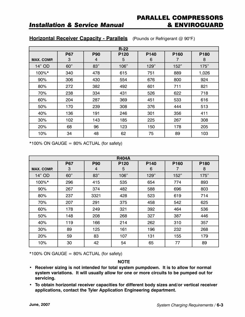
Horizontal Receiver Capacity - Parallels (Pounds or Refrigerant @ 90°F.)
R-22P67 P90 P120 P140 P160 P180
MAX. COMP. 3 4 5 6 7 8
14” OD 60” 83” 106” 129” 152” 175”
100%* 340 478 615 751 889 1,026
90% 306 430 554 676 800 924
80% 272 382 492 601 711 821
70% 238 334 431 526 622 718
60% 204 287 369 451 533 616
50% 170 239 308 376 444 513
40% 136 191 246 301 356 411
30% 102 143 185 225 267 308
20% 68 96 123 150 178 205
10% 34 48 62 75 89 103
*100% ON GAUGE = 80% ACTUAL (for safety)
R404AP67 P90 P120 P140 P160 P180
MAX. COMP. 3 4 5 6 7 8
14” OD 60” 83” 106” 129” 152” 175”
100%* 296 415 535 654 774 893
90% 267 374 482 588 696 803
80% 237 3321 428 523 619 714
70% 207 291 375 458 542 625
60% 178 249 321 392 464 536
50% 148 208 268 327 387 446
40% 119 166 214 262 310 357
30% 89 125 161 196 232 268
20% 59 83 107 131 155 179
10% 30 42 54 65 77 89
*100% ON GAUGE = 80% ACTUAL (for safety)
NOTE• Receiver sizing is not intended for total system pumpdown. It is to allow for normal
system variations. It will usually allow for one or more circuits to be pumped out for servicing.
• To obtain horizontal receiver capacities for different body sizes and/or vertical receiverapplications, contact the Tyler Application Engineering department.


Installation & Service ManualPARALLEL COMPRESSORS
& ENVIROGUARD
June, 2007 Start-Up Procedures / 7-1
SS EE CC TT II OO NN 77Start-Up ProceduresThe start-up procedures consist of three steps; leak testing, evacuation and the charging start-up procedures. Follow these procedures to prevent any problems in the start-up of the unit.
Leak Testing ProcedureThe success of all the subsequent (evacuation, charging and start-up) as well as successfuloperation of the system depends on a totally leak-free system.
CAUTIONDo not start any compressors before these procedures instruct you to do so. BEFORE STARTING, MAKE SURE THERE IS OIL IN THE COMPRESSOR. Serious compressor damage may result if all the steps are not followed properly. See page 8-5 for recommended oil usage.
1. The pilot circuitry ON-OFF switch, on the store power distribution panel, must be OFF.
2. Check that the compressor primary ON-OFF switches are all in the OFF position.
3. All the following valves must be OPEN:
• Discharge Service Valves on the compressors• Suction Service Valves on the compressors• Liquid Return Valve on the receiver (from remote condenser)• Liquid Outlet Valve on the receiver• All field supplied Hand Shut Off Valves• All Liquid Line Manifold Valves• All Suction Line Manifold Valves• All Hot Gas Manifold Valves• All Oil Equalization System Valves
4. Remove the black power wire from the multi-circuit time clock motor in the defrost control panel. This will prevent the clock from advancing until the start-up procedures are complete.
5. Tighten all electrical connections in all panels prior to energizing the power.
6. Turn ON the pilot circuit breaker.
7. Turn ON the power at the store distribution panel and adjust the time clock modules so that all systems are ON REFRIGERATION. Flip the system ON-OFF toggle switches on the panel to ON. This opens all the branch circuit liquid line solenoid valves. NOTE: Allcompressor switches must remain OFF (See step 2 above.)
8. Connect the necessary charging lines to introduce refrigerant and dry nitrogen into the system use 3/8” or larger evacuating/charging lines for proper system evacuation.
9. Backseat the receiver liquid outlet valve and connect a charging line to the valve gauge port connection. Pressurize the system with approximately 50 psi with refrigerant and thenbuild with nitrogen to 162 psi.
CAUTIONIf pressure greater than 162 psi is used for testing, disconnect the low pressure computer transducers, control lines and seal the pressure port. This is done to avoid damaging the control’s bellows.

PARALLEL COMPRESSORS& ENVIROGUARD
7-2 / Start-Up Procedures June, 2007
9. Using an electronic leak detector, carefully check the entire system for leaks. Special careshould be taken to inspect all joints. Check the line pressure gauge at the nitrogen tank for pressure fluctuations. A sharp drop in pressure indicates a leaky system.
10. Allow the system to stand for 24 hours with the pressure on (Nitrogen tank off). If no pressure changes are observed, the system is tight. If leaks are found, isolate that particular portion of the system by closing off the hand valves. Let the leak depressurizethe system at that point and repair the leak immediately.
NOTEThe use of nitrogen, or carbon dioxide, flowing at low pressure through the lines while they are being welded is necessary to assure relative freedom from the formation of oxides and scale. These can easily clog the small ports on the pilot operated and other valves in the system.
Evacuation Procedure
When the system is proven leak free, evacuate it using an efficient vacuum pump with clean orfresh oil and sufficient time to do a thorough job. Leave the system in a vacuum to aid incharging.
NOTEDue to recommended piping of heat recovery coils, it is necessary to field supply a temporary by-pass between the line downstream of the inlet check valve on the heat recovery coil and the discharge line downstream of the IPR hold back valve. Failure to by-pass the IPR will result in the inability to evacuate the reclaim coil. The by-pass line must be removed after evacuation to assure proper operation of the system. See piping schematics on page 4-1.
Evacuation Method
1. Attach vacuum pump to the system to be evacuated.
NOTETYLER provides large servicing ports at:
• Discharge line after the Oil Separator• Liquid line prior to the Filter• Suction Manifold• Return Manifold
2. Make sure the following valves are OPEN.
• Discharge Service Valves on compressors• Suction Service Valves on the compressors• Liquid Return Valve on the receiver (from remote condenser)• Liquid Outlet Valve on the receiver• All field supplied Hand Shut Off Valves• All Liquid Line Manifold Valves• All Suction Line Manifold Valves• All Hot Gas Manifold Valves
3. Draw vacuum down to 500 microns with vacuum pump. (System must hold 500 microns.)NOTE: 500 microns is the standard representing the absence of moisture in the system.

Installation & Service ManualPARALLEL COMPRESSORS
& ENVIROGUARD
June, 2007 Start-Up Procedures / 7-3
4. The system is now ready for charging. Remember that even the most careful evacuationsand purging will not clean up a system that has been carelessly put together.
NOTEMoisture and air must be removed from the system in order to avoid any possibilities of compressor burnouts. Complete evacuation (draw vacuum down to 500 microns) is one of the best ways to ensure the system is clean.
Parallel Charging & Start-Up Procedure
Be sure to use the appropriate refrigerant designed for the system. Low and Medium temperature systems typically use either R404A or R-22 refrigerant, depending on the system design. For charging of the TYLER Commercial Refrigeration system use the high side charging method.
FOR ENVIROGUARD SYSTEM CHARGING, see pages 24-10 & 24-11.
Follow these precautions prior to, and during, the charging procedure:
1. Make sure all system filters are properly installed and clean before charging the system.
2. All charging lines must be cleaned and purged to ensure they are free of air and moisture.
3. The system must be tested for leaks and evacuated properly prior to charging it with refrigerant.
4. Remember to wear safety goggles when transferring and charging refrigerants.
5. NEVER allow liquid refrigerant to reach the compressors. The liquid is not compressibleand will damage the compressors.
6. Be sure all temperature controls are set to the anticipated temperatures in each of the circuits.
7. Connect high and low side pressure gauges to common connection point or headers.
8. Make sure all fixtures are supplied with false loads prior to start-up.
9. INSURE PROPER OIL CHARGE BEFORE STARTING THE COMPRESSORS. (Use oil recommended by the manufacturer.)
NOTEThe manufacturer’s information is tagged to the compressor.
Charging & Start-Up
1. Use the charging tables on pages 6-1 & 6-2 to determine the proper amount of refrigerantto charge into the system.
2. Attach a refrigerant tank with gauge and dehydrator to the 3/8” Schrader Valve next to thedownstream regulator.
3. Fill the receiver with as much refrigerant as it will take (usually one tank).
4. Attach a refrigerant tank with gauge and dehydrator to the receiver outlet valve service port.(A 16 cubic inch drier should be used on a 145 pound cylinder.)
5. Close the receiver liquid outlet valve.
6. Slowly open the refrigerant tank valve and charge liquid refrigerant into the system. Thevacuum should pull nearly all the refrigerant from a 145 pound tank.

PARALLEL COMPRESSORS& ENVIROGUARD
7-4 / Start-Up Procedures June, 2007
7. Close the following valves:
• All liquid line manifold valves.• All suction manifold valves.
8. Choose a branch circuit and open both the suction and liquid service isolation valves 1/4 turn.
9. Turn ON the condenser fan circuit.
10. Start one of the compressors. Check and record compressor amperage readings.
11. Open the receiver outlet.
12. Slowly open the suction and liquid isolation valves on the chosen circuit 1/4 turn at a timeto activate the first branch circuit. Monitor activation of the first branch circuit during theopening of the liquid and suction service valve until there is assurance that the expansionvalve sensing bulbs are controlling refrigerant flow through the cases.
NOTERefrigeration circuits must be monitored during activation to protect the compressor from liquid slugging. Stop the compressor immediately if any abnormality is noted.
13. Monitor the oil level in the compressors. Add oil as required to maintain oil level at 1/4 to1/3 full in the sightglass. If foaming occurs, run compressors intermittently until foamingsettles. Before adding oil, check to see that the oil equalization system is operating properly. Oil should be added directly to the reservoir rather then individual compressors.(See Section 8, Oil Equalization System for more detail.)
NOTEPOE oils must be pumped into the system because of their high affinity to draw moisture.
14. Continue activation of the branch circuits, one at a time. Maintain no more that 50 psicharging pressure above the design suction pressure.
NOTEIn order to cut charging time, feed each circuit separately using refrigerant from a cylinder. Keep service valve closed to the manifold until the circuit is charged.
15. Adjust the EPR and TEV valve settings for their individual applications.
16. Continue activation of the refrigeration circuits until they are all on the line. Continue charging the circuits as necessary to maintain refrigerant level in the receiver. Check liquid line sightglass during charging, if bubbles are present it may indicate a low refrigerant charge. (However, occasional bubbling may occur.) The liquid level indication isa better charging indicator.
17. On electric defrost systems, check the defrost load amperage against the summary sheet.
18. Adjust the multi-circuit time clock settings for proper time termination and sequence ofdefrosting.
19. Check starters and heaters, contactor sizes and circuit breakers to ascertain correct selection and application.

Installation & Service ManualPARALLEL COMPRESSORS
& ENVIROGUARD
June, 2007 Start-Up Procedures / 7-5
20. Replace black power wire to the motor of the multi-circuit time clock, or reactivate thedefrost control.
21. Check the ability of the compressor motors to start after shut down (in effect simulating a power failure). Use an ammeter to determine operation of a loaded start.
22. Record the motor amperage at normal operating pressures and temperatures.
23. Check the remote condenser and heat recovery coil for proper operation.
24. Check oil reservoir level, if oil level is below the bottom sightglass, add oil until level can be seen or is above the sightglass. Red beads should be visible in the center of the sightglass.
25. On gas defrost systems, check to ensure the system operates properly during defrost.Description of operation is on pages 12-1 & 12-2.
26. Due to the use of refrigerants such as R404A and R-507; systems now require oil which ishydroscopic, meaning it will very rapidly absorb moisture. In addition the combination ofthe HFC refrigerants and the POE oils act as very good solvents. This can break loose and circulate contaminants that before may not have been a problem. In order to deliver a clean uncontaminated system, proper start-up procedures should be followed. To helpensure a clean system, filter changes should become part of the start-up procedure. Filters should be changed as needed. Example: Change drier filters at periodic intervals or 3 days, 3 weeks, and 3 months. Watch the moisture indicator and observe the color and transparency of the oil. Another good indication is pressure drop across the filter and if it reaches 3 pounds or more, it should be replaced. However, if proper evacuationprocedures are followed, and dry uncontaminated oil is installed in the system after theevacuation, the 3 month filter change may not be needed.
NOTEThe initial suction filters are shipped in place. A replacement set of suction filters are also shipped loose. These should be used to change the suction filters after initial startup (approx. 3 days). Liquid drier cores are also shipped loose for installation prior to startup, but after the system has been sealed.
Operational Check after Start-Up
When the system has been operating for at least 2 hours without any indication of problem,check the following items allowing the system to continue operations on automatic controls.
1. Check to see that all case fans are operating properly and rotating in the appropriate direction.
2. Check the setting of all thermostatic expansion valves for proper superheat.
3. Check the compressor operating parameters; head pressure, suction pressure, line voltage and compressor amperage. If any of the readings are not within the expected parameters (as noted on the nameplate and in this manual) determine the cause and correct.
4. Check the compressor oil level to ensure that it meets manufacturer’s specifications.


Installation & Service ManualPARALLEL COMPRESSORS
& ENVIROGUARD
June, 2007 Oil Control System / 8-1
SS EE CC TT II OO NN 88Oil Control System
The oil control system is made up of several devices working together to provide a constantsupply of recirculated oil to the compressors.
Oil Separator
As hot discharge gas leaves the compressors, it must first travel through the oil separator. The oil separator’s duty is to make the refrigeration system more efficient and to save energy.It does this by removing oil from the refrigerant vapors, which would otherwise travel through-out the system. Because oil is a lubricant, not a refrigerant, its presence in the refrigeration circuits will reduce the efficiency of the system.
Oil Separator Operation
An oil float (located in the bottom of the oil separator) opens or closes when a specific oil levelis reached in the oil separator The float is attached to a needle valve which opens as the floatrises to the upper limit of its travel. The needle valve is located in the line between the separator and the oil reservoir. When the valve opens, oil is forced to travel to the reservoirwhich is at a lower pressure.
During normal operation, the oil return line from the oil separator to the reservoir will be alternately hot and cool. This is caused by the oil float valve alternately opening and closingwhile returning oil to the reservoir. An oil return line at ambient temperature may suggest thatthe needle valve may be blocked by foreign matter or the oil strainer is plugged. If the oilreturn line is continually hot, the oil float valve may be leaking or being held open by foreignmatter. In either case, the oil separator and/or the oil strainer should be cleaned.
Other problems may be indicated by a continually hot oil return line. It may mean that a compressor is pumping excessive oil or the separator is too small for the compressors. This can be checked visually by installing a sightglass in the oil return line. If the oil return line iscold, it means that there is condensation of liquid refrigerant in the oil separator.
Oil Reservoir
Oil trapped in the oil separator is piped directly to the oil reservoir. Oil movement from the oil separator to the reservoir is induced by having the reservoir at a lower pressure that the separator. The pressure of the oil in the reservoir is reduced through a vent line to the suctionheader. A 20 pound oil differential check valve is placed in this vent line to keep the pressurein the oil reservoir 20 pounds above the suction pressure. This is to ensure oil flow to the compressor oil level controls from the reservoir. The oil separator operates at the same pressure as the compressor discharge gas. The reservoir will be at 20 pounds above the suction pressure, and the compressor crankcase will operate at the suction pressure. These differences in pressure ensure positive flow of lubricating oil throughout the oil equalization system.

PARALLEL COMPRESSORS& ENVIROGUARD
8-2 / Oil Control System June, 2007
Oil Level Controls (Oil Float)
The oil level control will receive oil from the reservoir at 20 pounds above the suction pressure.The control will meter oil flow to the compressor, thus maintaining at least the minimum oil level required to operate safely. As the level of the oil is lowered in the compressor crankcasethrough operation, the float in the oil level control is lowered. When the float drops to a certain point a needle valve will open allowing oil to flow back into the compressor crankcase.
TYLER’s default oil level controller is Sporlan’s OL-60XH. The orifice in each is sized to maintain proper oil flow in the pressure differential range of 5 to 90 psi.
When a parallel system employs lower temperature satellite compressors, (which operate at a suction pressure more than 15 psi lower than the suction pressure of the main suction group) a regulating valve Sporlan’s ADRI-1 1/4-0/75 or Y-1236C are used to step down the oil pressure feeding the oil level control(s) of the satellite(s). The outlet of the regulating valve isadjusted to maintain the same differential across the satellite’s oil level control as that which ismaintained across the oil level control on the main suction group. A minimum differential of 10psi and a maximum of 30 psi are required. Because the suction pressure on the main suctiongroup will rise with an increase in load or the end of a defrost period, it would be prudent touse a maximum pressure differential of 25 psi. (Refer to Figure 1.)

Installation & Service ManualPARALLEL COMPRESSORS
& ENVIROGUARD
June, 2007 Oil Control System / 8-3
When a high temperature satellite is employed, the reservoir is still vented to the main suctionmanifold, but the check valve in the vent line must be sized to raise the oil feed pressureapproximately 10 psi above the satellite suction pressure. That pressure is then stepped down with the regulating valve to approximately 20 psi above the suction pressure of the main.(Refer to Figure 2.)
The oil system for an internally compounded Carlyle system requires that the pressure differential across the oil level float control be approximately 20 psi. In addition the oil reservoiris vented to the interstage manifold. (See pages 22-4 & 22-6.)

PARALLEL COMPRESSORS& ENVIROGUARD
8-4 / Oil Control System June, 2007
Checking Oil Level
Oil level may be checked with the system either operating or idle. Some reservoirs areequipped with two sightglasses. Oil level should be maintained between the two sightglasses.Compressor oil level may be checked on the sightglass on each compressor crankcase. Thelevel may be viewed on the oil level control, if it is equipped with a sightglass.
CAUTIONThe level indicated on the oil level control sightglass may give a false indication of actual crankcase level. Use the sightglass on the compressor crankcase for an accurate oil level or to verify the oil level control sightglass reading. Improper compressor oil levels could cause damage to the compressor.
Oil Level Control Adjustment
The oil level control may be adjusted to vary the oil in the compressor crankcase. To reset theoil level control, remove the seal cap on the top of the control. Turn the adjustment clockwiseto lower and counterclockwise to raise the oil level. See chart below for the number of turnsrequired.
CAUTIONWhen setting OL60XH & OL1-CH float controls, DO NOT adjust beyond 9 turns down from the top stop or control may be damaged. For all other float controls, refer to O.E.M. for setting instructions and requirements.
NOTEThe oil level control is factory set at 3-1/2 turns clockwise from the top stop.
Adding Oil
Oil may be added to the system in several ways. However, the following method is the preferred one. You will need a piece of flared tubing attached to an oil pump. Remember, the oil and oil transfer equipment must be clean and dry. The oil must be the proper viscosityfor the compressor, the refrigerant, and the low side temperature.

Installation & Service ManualPARALLEL COMPRESSORS
& ENVIROGUARD
June, 2007 Oil Control System / 8-5
The Preferred Method of Adding Oil
1. Attach tubing with oil pump to the middle opening of the gauge manifold.
2. Attach the high pressure hose of the gauge manifold to the discharge service fitting and the low pressure hose to the 1/4” flare connection at the top of the oil reservoir.
3. Front seat the flare valve at the top of the oil reservoir to receive oil from the oil separator.
4. Purge the tubing using gas from the high pressure side.
5. After purging the tubing, immerse the oil pump in a container filled with clean refrigerant oil.
6. Open the 1/4” flare connection on the top of the reservoir.
7. Slowly open the low pressure isolation valve on the gauge manifold and use the oil pumpto deliver oil to the system reservoir from the container. It is important that some oil is left in the container so that the oil pump is always immersed. If not, air could be drawn into the system.
8. Shut the low pressure isolation valve on the gauge manifold when oil transfer is complete.
9. Open the flare valve at top of oil reservoir to receive oil from the separator.
NOTE:Oil requirements vary by refrigerant used and compressor manufacturer.
The most widely used refrigerant oils are as follows:
Mineral Oil Applications
• Copeland compressors use Sunisco 3G or 3GS with a viscosity rating of 150 SUS.• Carlyle compressors use Witco-Sunisco 3GS, Texaco-Capella WFI-32-150, or
Chevron-Zerol 150 with a viscosity rating of 150 SUS.
Polyol Ester Oil Applications (HFC’s)
• Copeland MT/LT recommends - Mobil EAL Artic 22 CC, and ICU EMKARATE RL 32CF.• Carlyle MT recommends - Mobil ARTIC EAL 68, Castrol SW68, Castrol E68,
ICI EMKARATE RL 68H, Lubrizol 2916S, and CPI SOLEST 68.• Carlyle LT recommends - Castrol SW68, Castrol E68, ICI EMKARATE RL 68H,
Lubrizol 2916S, and CPI SOLEST 68.
Carlyle Screw Compressor Applications
• Carlyle MT recommends - Castrol SW100, CPI SOLEST BVA 120, ICI EMKARATE RL 100S, and Castrol E100.
• Carlyle LT recommends - CPI SOLEST BVA 120, Castrol E100, and ICI EMKARATE RL 100S.
NOTECastrol SW100 is not recommended for low temperature operations.

PARALLEL COMPRESSORS& ENVIROGUARD
8-6 / Oil Control System June, 2007
Bitzer/Copeland Screw Compressor Applications
• Bitzer/Copeland model SHM/L for MT/LT/HT HFC’s recommends - CPI Solest 170.• Bitzer/Copeland model SHM/L for MT/LT R22 recommends - CPI CP4214-150.• Bitzer/Copeland model SHM/L for HT R22 recommends - CPI CP4214-320.
Removing Oil
Occasionally problems in line sizing or system operation may cause oil to be trapped in anevaporator or suction line, and large amounts of oil were added to compensate for this oil logging. When the problem has been solved and corrected, the excess oil will return to thecompressor crankcase.
CAUTIONIf this excess oil is not removed from the system, compressor damage will be the likely result.
To remove excess oil from the compressor via the oil fill plug:
1. With the compressor OFF, close the compressor suction valve and reduce the crankcasepressure to 1 to 2 psi.
2. Shut the discharge service valve.
3. Carefully loosen the fill plug, allowing any pressure to bleed off before fully removing the plug.
4. Remove the plug and insert a 1/4” O.D. copper tube into the plug hole. Use a tube of sufficient length to reach the bottom of the crankcase and the external end can be bentdown below the level of the crankcase.
5. Wrap a clean rag tightly around the oil fill opening and crack the suction service valve to pressurize the crankcase to about 5 psi. Oil will be forced out of the drain line and willcontinue to drain due to the siphon effect on the oil (the residual refrigerant pressure willprevent any serious amount of moisture or foreign particles from entering the compressor.
6. After the desired amount of oil has been drained, remove the drain tube and reinstall the oil fill plug.
7. Open the compressor suction and discharge service valves.

Installation & Service ManualPARALLEL COMPRESSORS
& ENVIROGUARD
June, 2007 Pressure Regulator Settings / 9-1
SS EE CC TT II OO NN 99Pressure Regulator Settings
These settings are given as initial adjustment guidelines. The settings required for each individual system may vary.
“STANDARD” settings are given as comparisons and can be used for single compressor-remote condenser systems which may have the IPR and OPR. A single compressor systemcannot take advantage of reduced cool weather loads and increased system capacity.
“NC” systems feature two, and up to eight compressors, with solid state or conventional pressure controls to cycle off needed compressors. “NC-2” is the same with an additional liquid bypass for maximizing natural liquid subcooling. “NC-3” includes mechanical subcooling.
IPR - Inlet (Upstream) Pressure Regulator
STANDARD NO FLOATING HEAD
TYPE OF ELECTRIC ELECTRIC GASDEFROST OR GAS LOW MED DEFROST
R-22 195 PSIG 127 PSIG 175 PSIG 146 PSIG
R404A 230 PSIG 150 PSIG 189 PSIG 173 PSIG
R-507 235 PSIG 155 PSIG 192 PSIG 179 PSIG
NOTEIf the IPR valve has been replaced with an OLDR valve, the OLDR should be adjusted to a differential pressure equal to the IPR setting minus the OPR setting.
IPR - Inlet Pressure Regulator on Heat Recovery Coil
NC FLOATING HEAD NC-2, NC-3 SYSTEMS
TYPE OF GAS GASDEFROST ELECTRIC DEFROST ELECTRIC DEFROST
R-22 158 PSIG 158 PSIG 158 PSIG 158 PSIG
R404A 188 PSIG 188 PSIG 188 PSIG 188 PSIG
R-507 195 PSIG 195 PSIG 195 PSIG 195 PSIG
The IPR valve is shipped loose for installation downstream of the Heat Recovery Coil. Thisvalve is used to raise system discharge pressure to get more heat out of the hot gases passingthrough the coil.

PARALLEL COMPRESSORS& ENVIROGUARD
9-2 / Pressure Regulator Settings June, 2007
The OPR valve supplies high side pressure to the receiver whenever the pressure falls below a set point.
DDPR Valve on Gas Defrost Systems (Optional)
The DDPR is a valve that maintains an adjustable pressure differential between its inlet and outlet pressures. This is accomplished in its normal, non-energized state. When the DDPRvalve is energized, the valve opens and equalizes the inlet and outlet pressures. When all hot gas circuits in a system are in refrigeration mode, the valve should be energized.
NOTEThe minimum recommended differential pressure setting of the DDPR is 20 psi.
STANDARD NC FLOATING HEAD NC-2, NC-3 SYSTEMS
TYPE OF ELECTRIC ELECTRIC GAS ELECTRIC GASDEFROST OR GAS LOW MED DEFROST LOW MED DEFROST
R-22 170 PSIG 102 PSIG 150 121 PSIG 102 PSIG 150 121 PSIG
R404A 205 PSIG 125 PSIG 164 148 PSIG 125 PSIG 164 148 PSIG
R-507 210 PSIG 130 PSIG 167 154 PSIG 130 PSIG 167 154 PSIG
OPR - Outlet (Downstream) Pressure Regulator
Installation & Service ManualPARALLEL COMPRESSORS
& ENVIROGUARD
June, 2007 OLDR Liquid Differential Regulator Valve / 10-1
SS EE CC TT II OO NN 1100OLDR Liquid Differential Regulator Valve
The OLDR valve has a solenoid bypass feature so the valve can either remain fully open or operate to maintain a differential. The OLDR valve fails to the open position.
In the differential mode, the pilot differential valve controls the valve by varying the pressure on top of the main piston. Inlet pressure enters the pilot assembly through an external tubeconnected to the inlet fitting. The outlet of the pilot differential valve is connected to the outletfitting with an external tube. The valve will open only as far as necessary to maintain the pilotvalve setting. The pilot valve modulates the piston from partially open to partially closed tomaintain its setting. (See Figure 1 on page 10-2.)
In the fully open mode, the pilot port is closed. This stops the flow to the chamber above themain piston. The refrigerant above the main piston is bled to the outlet through an orifice in the pilot differential piston. The inlet pressure then moves the piston up and the valve opens.(See Figure 3 on page 10-2.)
Setting Procedure
The OLDR is set by turning the adjusting stem located under the cap on the pilot differentialvalve. Turning the stem clockwise increases the setting, counterclockwise decreases the setting. Adjustments must be made with the valve in its differential mode and no refrigeratedcases in defrost, so that the head pressure is normal. Artificial low head pressure at the initiation of defrost can prevent a differential from occurring, thereby making it impossible to set the valve. ALWAYS set the OLDR when no cases are in defrost.
Once the pilot valve is set, it will modulate to maintain this differential setting during defrost.However, there are several system conditions that can cause the differential to change beyond the valve’s control and still be acceptable:
1. When a defrost is initiated the head pressure may fall. It can take several minutes for thedifferential to be created while the head pressure returns to normal.
2. If there is a very low requirement for refrigeration, and therefore a low demand for liquidrefrigerant, the differential may never build up enough to reach the valve setting.
3. As a gas defrost cycle progresses, condensing occurs in the evaporator in defrost at aslower rate. Therefore, there is more gas present in the evaporators, which results in ahigher natural pressure drop. It is possible for this natural pressure drop to be higher than the differential valve’s setting.
IMPORTANTTo verify valve operation, if no differential is occurring between the liquid header and the receiver during defrost, take all cases out of defrost and then put the valve in its differential mode and check its setting. If the valve is maintaining its set point with normal head pressures and no cases in defrost, then the valve is opening correctly and some other system condition such as outlined previously may be causing the problem.

PARALLEL COMPRESSORS& ENVIROGUARD
10-2 / OLDR Liquid Differential Regulator Valve June, 2007
OLDR Valve on Gas Defrost Systems
In order for the reverse flow to occur during gas defrost, the pressure of the gas defrost mani-fold must be greater than the pressure of the liquid header. The OLDR valve is used to createthe differential required when a circuit goes into defrost. The valve is in the differential modewhen energized. It uses an MKC-2 coil and fails in the full open position.
OLDR Valve Illustrations
The following chart lists the differential pressure settings for the OLDR at various heights of netliquid lifts from the lowest fixture liquid line elevation to the condenser inlet manifold. Settingsare presented and include the pressure drops for the liquid line, check valves and the defrostreturn solenoid valve.
Differential Pressure Settings for OLDR at Various Heights Chart
ELEVATION PSID ELEVATION PSID
15 20 30 30
20 25 35 32
25 27 40 35
NOTEThe OLDR valve should be set at a minimum differential of 20 psi.

Installation & Service ManualPARALLEL COMPRESSORS
& ENVIROGUARD
June, 2007 Parallel Pressure Control Settings / 11-1
SS EE CC TT II OO NN 1111Parallel Rack Pressure Control Settings (PSIG)
These settings are “average” and will have to be adjusted to suit the particular store and caseline-ups. Use an accurate gauge to make settings.
Use pressure settings as backup with electronic rack control.
CUT IN / CUT OUT PRESSURE SETTINGS (PSIG)
COMPRESSORS 8 7 6 5 4 3 2 1
R-22 LOW CUT IN 5 6 7 8 9 10 11 12
CUT OUT 0 0 0 0 0 0 0 1
R-22 MED CUT IN 31 32 33 34 35 36 37 38
CUT OUT 21 22 23 24 25 26 27 28
R404A* LOW CUT IN 9 10 11 12 13 14 15 16
CUT OUT 0 0 1 2 3 4 5 6
R404A* MED CUT IN 43 44 45 46 47 48 49 50
CUT OUT 33 34 35 36 37 38 39 40
* also applies to R-507
Pressure Cycling Set Points for Condenser Fans
REFRIGERANTSR404A / R-507 R-22
FANS OR DEFROST TYPES & SETTINGSPAIRS OF HOT GAS ELECTRIC HOT GAS ELECTRIC
FANS ON / OFF ON / OFF ON / OFF ON / OFF
6 240 / 220 200 / 180 210 / 190 170 / 150
5 230 / 210 190 / 170 200 / 180 160 / 140
4 220 / 200 180 / 160 190 / 170 150 / 130
3 210 / 190 170 / 150 180 / 160 140 / 120
2 200 / 180 160 / 140 170 / 150 130 / 110
1 190 / 170 150 / 130 160 / 140 120 / 100
0 <170 <130 <140 <100
• High Pressure CUT OUT 390-395 PSIG• Pressure Relief Valve 450 PSIG

PARALLEL COMPRESSORS& ENVIROGUARD
11-2 / Parallel Pressure Control Settings June, 2007
Remote Condenser Fan Settings
NOTEChart for ambient control usage only.
Setting Suction Pressure Differential & Time Delay
The pressure differential is the suction pressure band that the compressor(s) will try to maintain. This band can be set from 1 to 10 pounds. TYLER recommends setting the differential at 4 pounds initially.
Time Delay Values
Time delay is the time period that the compressor will operate or remain idle after a specificpressure set point has been reached. This tends to minimize the amount of compressorcycling required to maintain a specific pressure differential. “Minimum ON” time is the time the compressor runs after it reaches its target pressure. “Minimum OFF” time is the time the com-pressor waits to start. TYLER recommends the following “Minimum ON” and “Minimum OFF”time settings:
“Minimum ON” time should be less than 15 seconds.
“Minimum OFF” time should be 2 minutes or less.
Of course these time and pressure differentials will vary depending on system characteristics of the loads being refrigerated and will have to be adjusted during the start-up period.
NOTESystems operating on electronic or computer controls, will operate the compressors in such a way as to achieve the ideal suction pressures. The systems still require setting pressure differentials and time delays as back-ups.
FANS OR PAIRS HEADEROF FANS FAN 1 FAN 2 FAN 3 FAN 4 FAN 5
2 OFF @ 42°F
3 OFF @ 42°F
4 OFF @ 42°F 45 / 40°F
5 OFF @ 42°F 45 / 40°F 59 / 53°F
6 OFF @ 42°F 45 / 40°F 59 / 53°F 69 / 63°F 69 / 63°F
DROP LEG TEMPERATURE @ INLET
TEMP