installation & service manual for tx9200/tx9500 series ... manual.pdf · 4 any and all tormax...
TRANSCRIPT

1
Installation & Service Manual forTX9200/TX9500 SERIES SLIDING
DOOR CONCEALED MOUNT
SURFACE MOUNT&
FLUSH MOUNT
TORMAX TECHNOLOGIES, INC.11803 Starcrest Dr.San Antonio, TX 78247210-494-3551210-494-5930 (FAX)888-685-3707 [email protected]
ISSUE DATE: 06/03/08P/N : US800887REV B

2

3
TABLE OF CONTENTS
SECTION PAGE
SAFETY AND WARNINGS1. HEADER AND JAMB ASSEMBLY2. HEADER/JAMB ASSEMBLY PREPARATION3. HEADER/JAMB ASSEMBLY INSTALLATION4. THRESHOLD INSTALLATION5. BOTTOM DOOR GUIDE INSTALLATION6. O-PANEL INSTALLATION7. P-PANEL INSTALLATION8. SX PANEL PREPARATION9. SX PANEL INSTALLATION10. SX PANEL ALIGNMENT11. ACCESS CONTROL12. BUMPER ADJUSTMENT13. FUNCTION CONTROL PANEL INST. AND
OPERATION14. I-ONE SENSOR INSTALLATION15. SIGNAGE16. POWERING UP THE TX920017. INITIAL START UP
FINAL CHECKLIST
TROUBLE SHOOTING GUIDEFAULT CODE DIAGNOSIS/DESCRIPTIONSTERMINAL DESIGNATION (TCP-51LC)AUTO CONFIGURATION (TCP-51LC)TCP 51-LC WIRING DIAGRAMTERMINAL DESIGNATION (TCP-51 & 101)AUTO CONFIGURATION (TCP-51 & 101)TCP 51/101 WIRING DIAGRAMI-ONE SENSOR QUICK SET UP
4556789-101112-1314-1516-17181919-21
2222222324
2525-2627282930313233-35

4
ANY AND ALL TORMAX EQUIPMENT MUST BE INSTALLED AND SERVICED BY AN AAADM CERTIFIED TECHNICIAN, TO MEET THE CURRENT ANSI STANDARD A156.10 AND ANY LOCAL OR STATE BUILDING CODES.
NOTE: TORMAX AUTOMATIC RECOMMENDS THE USE OF A WATER LEVEL AND A PLUMB BOB TO PROPERLY INSTALL ANY DOOR PACKAGE PROVIDED. AN IMPROPER INSTALLATION COULD LEAD TO PREMATURE WEAR OF MOVING PARTS, AN UNPLEASING APPEARANCE, AND/OR SERVICE ISSUES FOR THE CUSTOMER.
NOTE: ALL PRIMARY ELECTRICAL CONNECTIONS SHOULD BE COMPLETED BY A LICENSED ELECTRICIAN!
THE HEADER AND JAMBS SHOULD BE ASSEMBLED ON THE FLOOR AND LIFTED INTO PLACE. IT IS ADVISED TO USE A LIFT ON LARGER ASSEMBLIES. CARE SHOULD BE TAKEN TO PROTECT THE FINISH ON THE UNIT AT ALL TIMES.
INSTALLATION OF A TX9000 SERIES UNIT SHOULD NEVER BE ATTEMPTED BY ONE INDIVIDUAL.
THIS SYMBOL WILL BE USED THROUGHOUT THIS TEXT TO INDICATE A SHOCK HAZARD. SHOCK HAZARDS CAN RESULT IN SERIOUS INJURY OR DEATH.
! THIS SYMBOL WILL BE USED THROUGHOUT THIS TEXT TO INDICATE A POINT OF EXTRA IMPORTANCE.
5
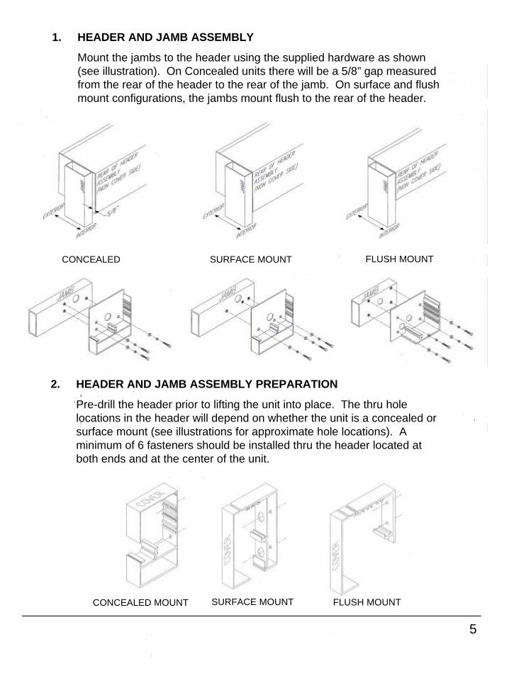
1. HEADER AND JAMB ASSEMBLY
Mount the jambs to the header using the supplied hardware as shown (see illustration). On Concealed units there will be a 5/8” gap measured from the rear of the header to the rear of the jamb. On surface and flush mount configurations, the jambs mount flush to the rear of the header.
CONCEALED SURFACE MOUNT
CONCEALED MOUNT SURFACE MOUNT
2. HEADER AND JAMB ASSEMBLY PREPARATION
Pre-drill the header prior to lifting the unit into place. The thru hole locations in the header will depend on whether the unit is a concealed or surface mount (see illustrations for approximate hole locations). A minimum of 6 fasteners should be installed thru the header located at both ends and at the center of the unit.
FLUSH MOUNT
FLUSH MOUNT

6
3. HEADER AND JAMB ASSEMBLY INSTALLATION
DETERMINE THE HIGHEST POINT OF YOUR FLOOR BY USING THE WATER LEVEL (SEE EXAMPLE BELOW).
Lift the header and jamb assembly into place, level and secure the unit with the appropriate fasteners. Plumb and secure each jamb tube as shown. Reference illustrations below.
Securing the jambs will depend on the possibilities provided by the work environment. It is suggested that the jambs be secured at both ends and at the center. Also, that fasteners be selected and located to limit visibility on the final assembly.
In the event that there is nothing to mount the jamb to horizontally, an L-bracket can be installed at the bottom of the jamb. L-brackets should be installed to provide the most support in the least visible location possible.
NOTE: On TX9500 ALL GLASS Models the Photo Beams will be installed in the prepared jamb tubes at this time.
6
7
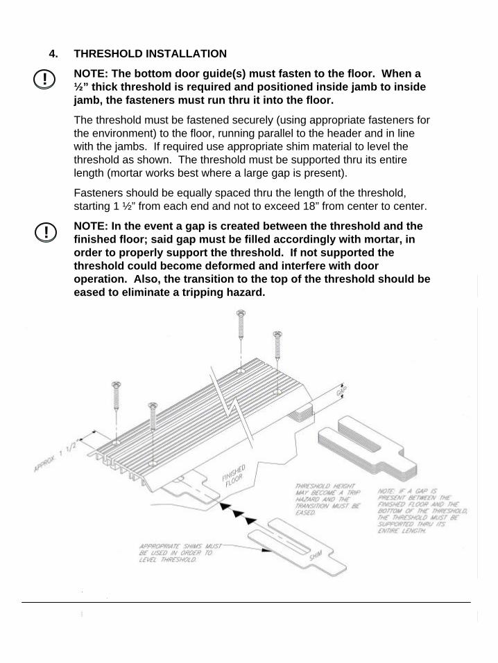
4. THRESHOLD INSTALLATION
NOTE: The bottom door guide(s) must fasten to the floor. When a½” thick threshold is required and positioned inside jamb to inside jamb, the fasteners must run thru it into the floor.
The threshold must be fastened securely (using appropriate fasteners for the environment) to the floor, running parallel to the header and in line with the jambs. If required use appropriate shim material to level the threshold as shown. The threshold must be supported thru its entire length (mortar works best where a large gap is present).
Fasteners should be equally spaced thru the length of the threshold, starting 1 ½” from each end and not to exceed 18” from center to center.
NOTE: In the event a gap is created between the threshold and the finished floor; said gap must be filled accordingly with mortar, in order to properly support the threshold. If not supported the threshold could become deformed and interfere with door operation. Also, the transition to the top of the threshold should be eased to eliminate a tripping hazard.
!
!
8
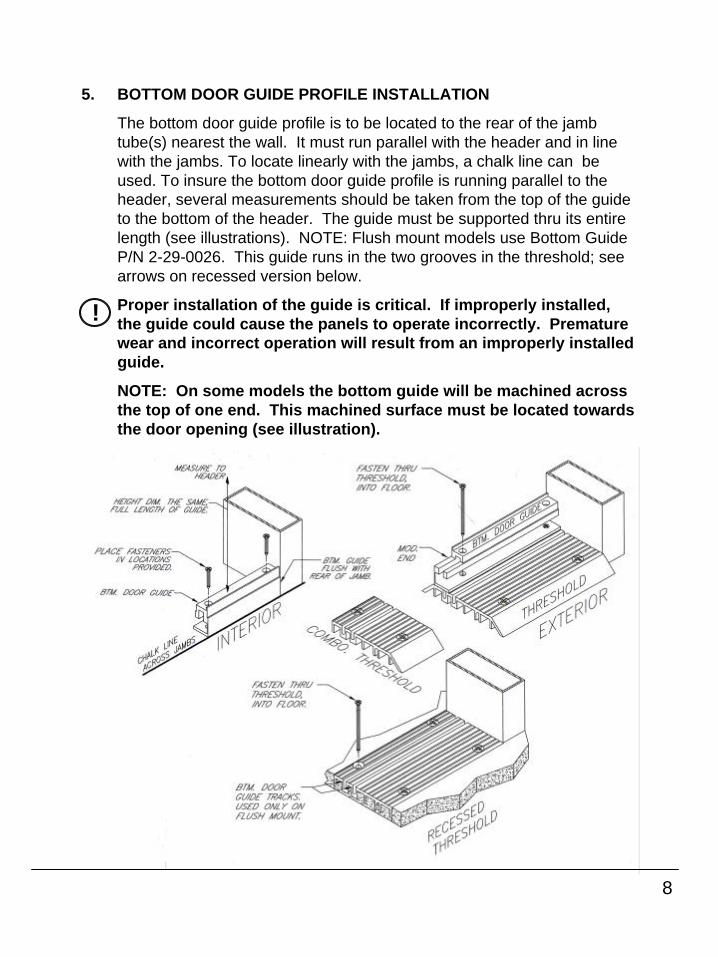
5. BOTTOM DOOR GUIDE PROFILE INSTALLATION
The bottom door guide profile is to be located to the rear of the jamb tube(s) nearest the wall. It must run parallel with the header and in line with the jambs. To locate linearly with the jambs, a chalk line can be used. To insure the bottom door guide profile is running parallel to the header, several measurements should be taken from the top of the guide to the bottom of the header. The guide must be supported thru its entire length (see illustrations). NOTE: Flush mount models use Bottom Guide P/N 2-29-0026. This guide runs in the two grooves in the threshold; see arrows on recessed version below.
Proper installation of the guide is critical. If improperly installed, the guide could cause the panels to operate incorrectly. Premature wear and incorrect operation will result from an improperly installed guide.
NOTE: On some models the bottom guide will be machined across the top of one end. This machined surface must be located towards the door opening (see illustration).
!
9
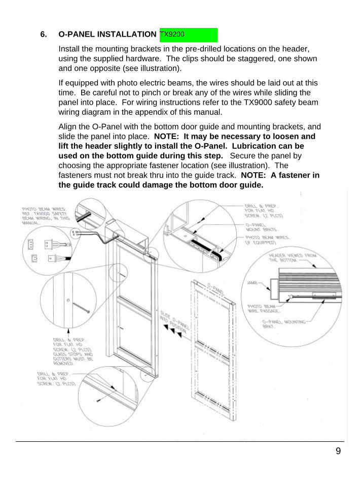
6. O-PANEL INSTALLATION
Install the mounting brackets in the pre-drilled locations on the header, using the supplied hardware. The clips should be staggered, one shown and one opposite (see illustration).
If equipped with photo electric beams, the wires should be laid out at this time. Be careful not to pinch or break any of the wires while sliding the panel into place. For wiring instructions refer to the TX9000 safety beam wiring diagram in the appendix of this manual.
Align the O-Panel with the bottom door guide and mounting brackets, and slide the panel into place. NOTE: It may be necessary to loosen and lift the header slightly to install the O-Panel. Lubrication can be used on the bottom guide during this step. Secure the panel by choosing the appropriate fastener location (see illustration). The fasteners must not break thru into the guide track. NOTE: A fastener in the guide track could damage the bottom door guide.
10
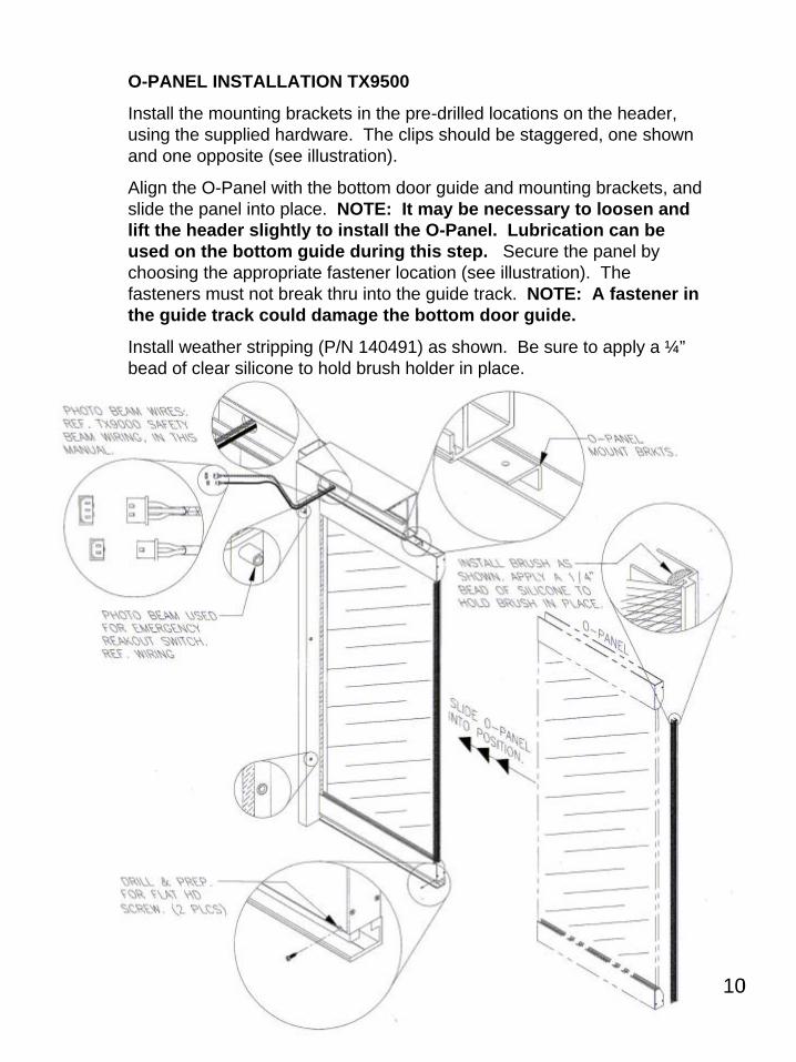
O-PANEL INSTALLATION TX9500
Install the mounting brackets in the pre-drilled locations on the header, using the supplied hardware. The clips should be staggered, one shown and one opposite (see illustration).
Align the O-Panel with the bottom door guide and mounting brackets, and slide the panel into place. NOTE: It may be necessary to loosen and lift the header slightly to install the O-Panel. Lubrication can be used on the bottom guide during this step. Secure the panel by choosing the appropriate fastener location (see illustration). The fasteners must not break thru into the guide track. NOTE: A fastener in the guide track could damage the bottom door guide.
Install weather stripping (P/N 140491) as shown. Be sure to apply a ¼”bead of clear silicone to hold brush holder in place.
10
11
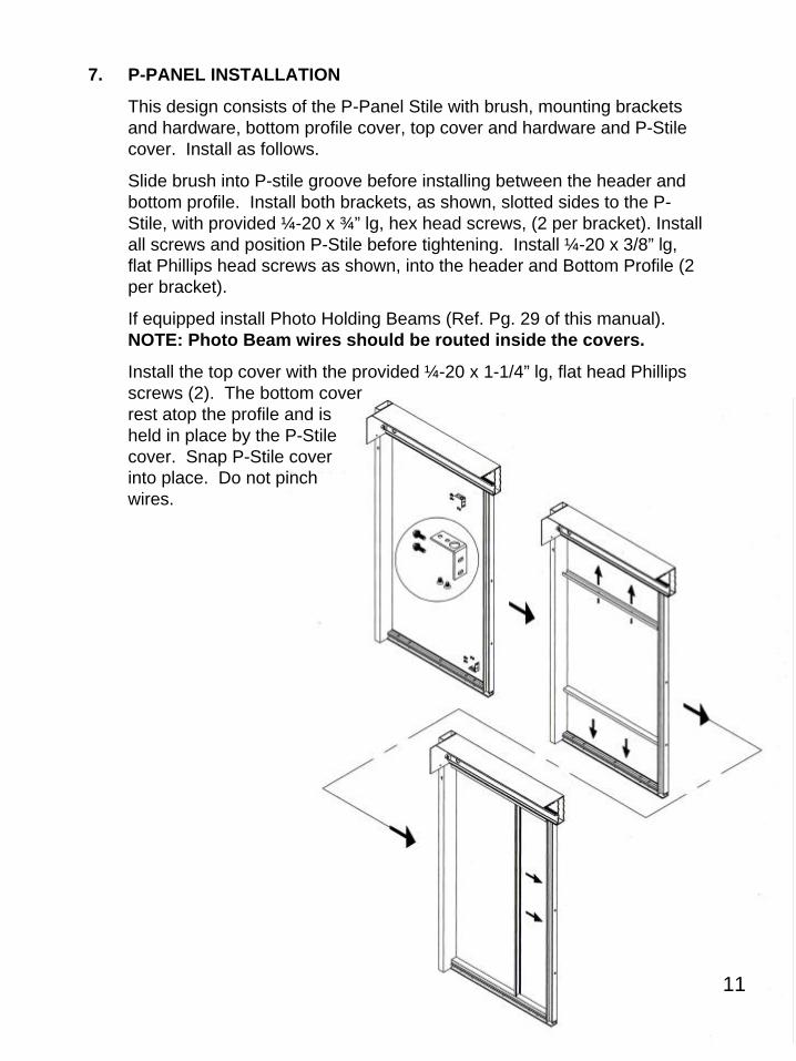
7. P-PANEL INSTALLATION
This design consists of the P-Panel Stile with brush, mounting brackets and hardware, bottom profile cover, top cover and hardware and P-Stile cover. Install as follows.
Slide brush into P-stile groove before installing between the header and bottom profile. Install both brackets, as shown, slotted sides to the P-Stile, with provided ¼-20 x ¾” lg, hex head screws, (2 per bracket). Install all screws and position P-Stile before tightening. Install ¼-20 x 3/8” lg, flat Phillips head screws as shown, into the header and Bottom Profile (2 per bracket).
If equipped install Photo Holding Beams (Ref. Pg. 29 of this manual). NOTE: Photo Beam wires should be routed inside the covers.
Install the top cover with the provided ¼-20 x 1-1/4” lg, flat head Phillips screws (2). The bottom cover rest atop the profile and is held in place by the P-Stile cover. Snap P-Stile cover into place. Do not pinch wires.
11
12
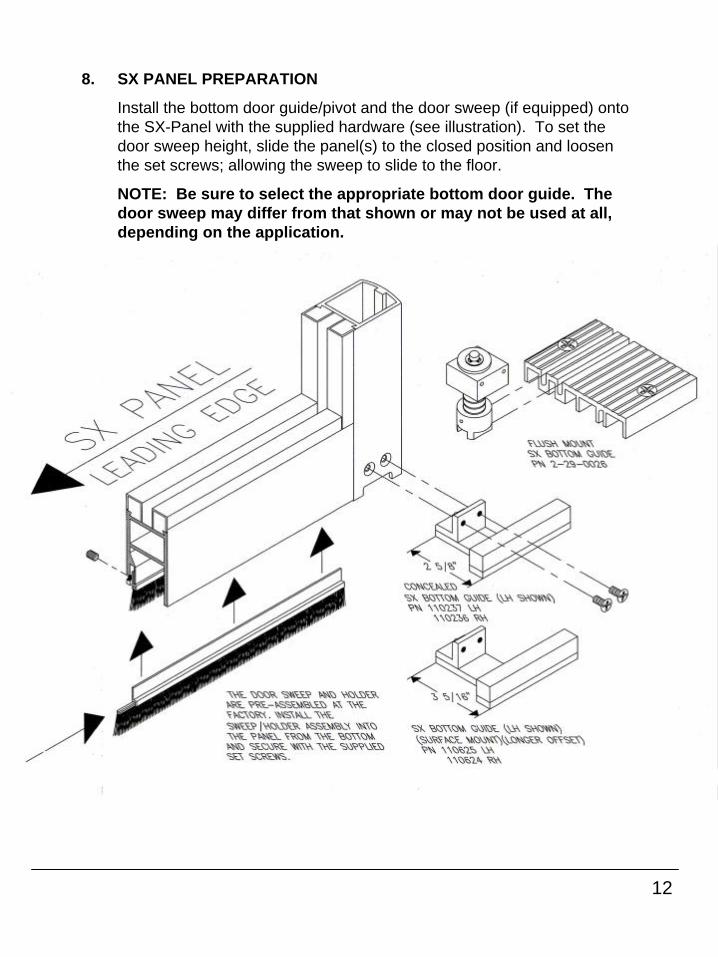
8. SX PANEL PREPARATION
Install the bottom door guide/pivot and the door sweep (if equipped) onto the SX-Panel with the supplied hardware (see illustration). To set thedoor sweep height, slide the panel(s) to the closed position and loosen the set screws; allowing the sweep to slide to the floor.
NOTE: Be sure to select the appropriate bottom door guide. Thedoor sweep may differ from that shown or may not be used at all,depending on the application.
13
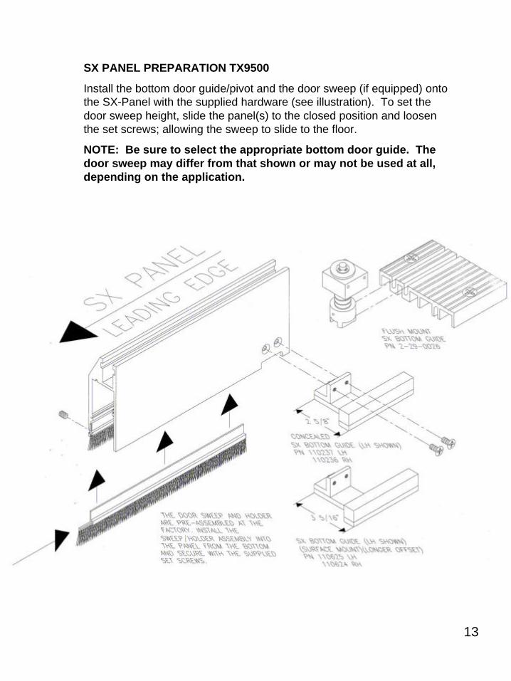
SX PANEL PREPARATION TX9500
Install the bottom door guide/pivot and the door sweep (if equipped) onto the SX-Panel with the supplied hardware (see illustration). To set thedoor sweep height, slide the panel(s) to the closed position and loosen the set screws; allowing the sweep to slide to the floor.
NOTE: Be sure to select the appropriate bottom door guide. Thedoor sweep may differ from that shown or may not be used at all,depending on the application.

14
9. SX PANEL INSTALLATION
Position the trolleys “approximately” to accept the SX-Panel.
NOTE: The trolleys are shipped with the anti-risers tight against the track to prevent damage in shipment. The anti-risers must be loosened to re-position the trolleys.
Loosen the two panel mounting bolts (on top of the SX-Panel) until only two full threads are engaged. Position the SX-Panel so that it will slide behind the drive unit while aligning the bottom door guide/pivot and guide channel. Align the trolleys and bolts and slide the two together. HINT: Adjusting the trolley height lower can be helpful if the panel is too heavy to lift.
15
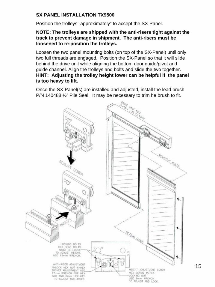
SX PANEL INSTALLATION TX9500
Position the trolleys “approximately” to accept the SX-Panel.
NOTE: The trolleys are shipped with the anti-risers tight against the track to prevent damage in shipment. The anti-risers must be loosened to re-position the trolleys.
Loosen the two panel mounting bolts (on top of the SX-Panel) until only two full threads are engaged. Position the SX-Panel so that it will slide behind the drive unit while aligning the bottom door guide/pivot and guide channel. Align the trolleys and bolts and slide the two together. HINT: Adjusting the trolley height lower can be helpful if the panel is too heavy to lift.
Once the SX-Panel(s) are installed and adjusted, install the lead brush P/N 140488 ½” Pile Seal. It may be necessary to trim he brush to fit.

16
10. SX PANEL ALIGNMENT
The alignment of the SX-Panel is very important to the functionality of the TX9000 series sliding door(s). Adjustments to the panel must be done with the 13mm bolts slightly loose. After all adjustments are completed, the 13mm bolts can be re-tightened and all the anti-risers must be adjusted to have a gap of .020”(approx. the thickness of a credit card).
NOTE: Try to mount the panel as close as possible to the final hanging position, to minimize the adjustments.
The moving panels should contact the seals and/or felts only slightly in order to minimize drag.
Use the following steps to align the moving panels:
The first adjustment should be to lift the panel to the proper operating height. There should be even contact between the door sweep andthreshold or finished floor.
The second adjustment is to position the panel the proper distance away from the header. The panel should contact the felt only slightly and evenly thru its length. Adjust this by sliding the panel towards or away from the felt brush on the header. When the panel is correct the panel mounting bolts can be tightened.
!
CONCEALED/SURFACE MOUNT FLUSH MOUNT
17
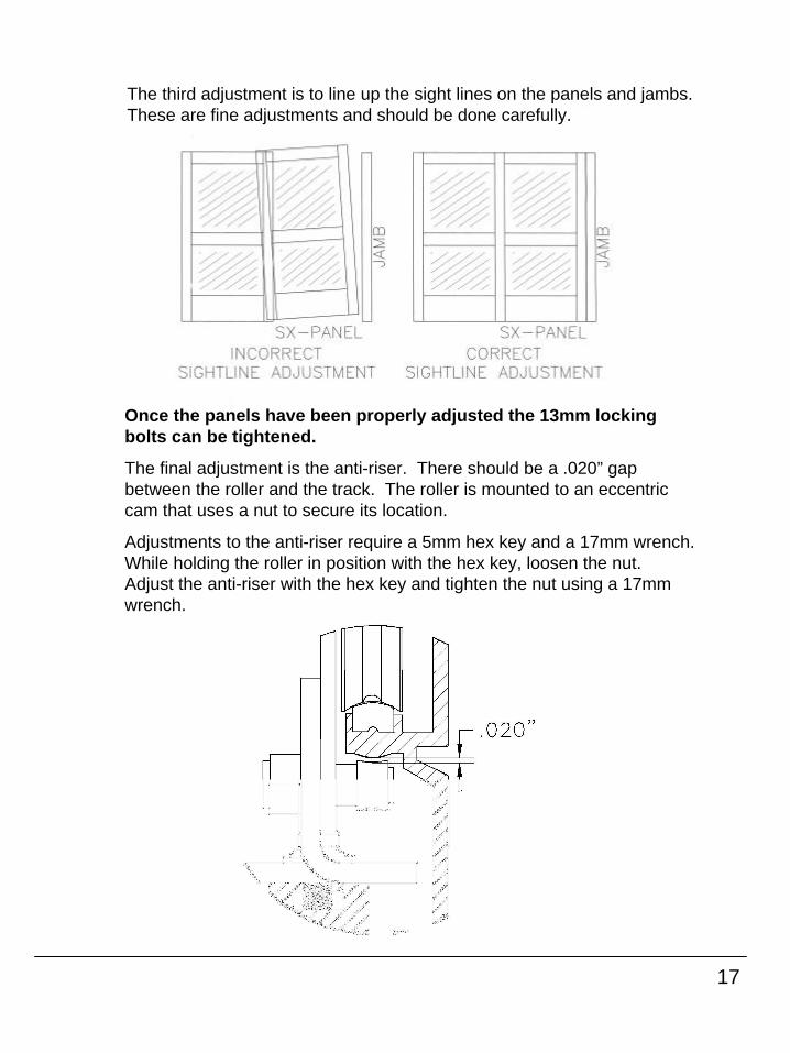
The third adjustment is to line up the sight lines on the panels and jambs. These are fine adjustments and should be done carefully.
Once the panels have been properly adjusted the 13mm locking bolts can be tightened.
The final adjustment is the anti-riser. There should be a .020” gap between the roller and the track. The roller is mounted to an eccentric cam that uses a nut to secure its location.
Adjustments to the anti-riser require a 5mm hex key and a 17mm wrench. While holding the roller in position with the hex key, loosen the nut. Adjust the anti-riser with the hex key and tighten the nut using a 17mm wrench.
18
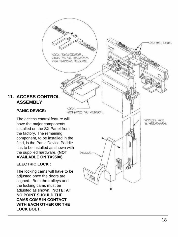
11. ACCESS CONTROL ASSEMBLY
PANIC DEVICE:
The access control feature will have the major components installed on the SX Panel from the factory. The remaining component, to be installed in the field, is the Panic Device Paddle. It is to be installed as shown with the supplied hardware. (NOT AVAILABLE ON TX9500)
ELECTRIC LOCK :
The locking cams will have to be adjusted once the doors are aligned. Both the trolleys and the locking cams must be adjusted as shown. NOTE: AT NO POINT SHOULD THE CAMS COME IN CONTACT WITH EACH OTHER OR THE LOCK BOLT.
19
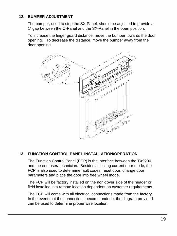
12. BUMPER ADJUSTMENT
The bumper, used to stop the SX-Panel, should be adjusted to provide a 1” gap between the O-Panel and the SX-Panel in the open position.
To increase the finger guard distance, move the bumper towards the door opening. To decrease the distance, move the bumper away from the door opening.
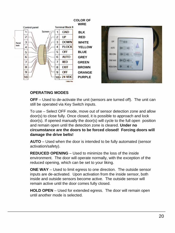
13. FUNCTION CONTROL PANEL INSTALLATION/OPERATION
The Function Control Panel (FCP) is the interface between the TX9200 and the end user/ technician. Besides selecting current door mode, the FCP is also used to determine fault codes, reset door, change door parameters and place the door into free wheel mode.
The FCP will be factory installed on the non-cover side of the header or field installed in a remote location dependent on customer requirements.
The FCP will come with all electrical connections made from the factory. In the event that the connections become undone, the diagram provided can be used to determine proper wire location.
20
BLK
COLOR OF WIRE
RED
WHITEYELLOWBLUE
GREY
GREEN
BROWN
ORANGEPURPLE
OPERATING MODES
OFF – Used to de-activate the unit (sensors are turned off). The unit can still be operated via Key Switch inputs.
To use – Select OFF mode, move out of sensor detection zone and allow door(s) to close fully. Once closed, it is possible to approach and lock door(s). If opened manually the door(s) will cycle to the full open position and remain open until the detection zone is cleared. Under no circumstance are the doors to be forced closed! Forcing doors will damage the drive belts!
AUTO – Used when the door is intended to be fully automated (sensor activation/safety).
REDUCED OPENING – Used to minimize the loss of the inside environment. The door will operate normally, with the exception of the reduced opening, which can be set to your liking.
ONE WAY – Used to limit egress to one direction. The outside sensor inputs are de-activated. Upon activation from the inside sensor, both inside and outside sensors become active. The outside sensor will remain active until the door comes fully closed.
HOLD OPEN – Used for extended egress. The door will remain open until another mode is selected.
21
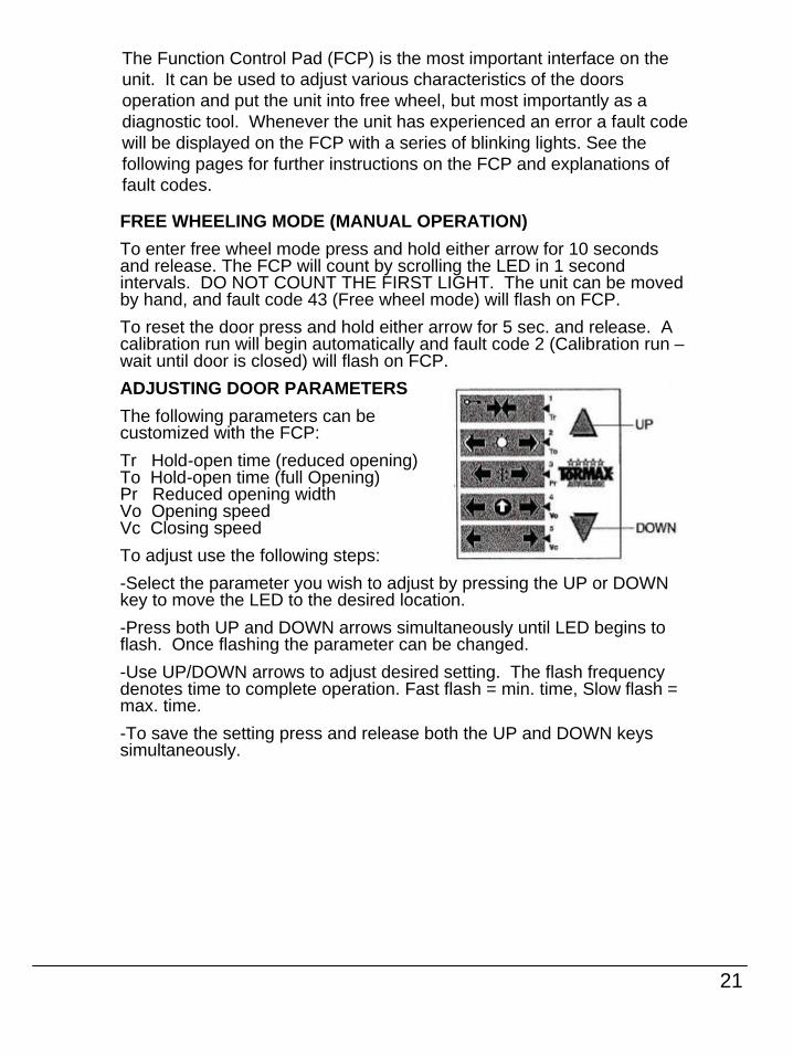
The Function Control Pad (FCP) is the most important interface on the unit. It can be used to adjust various characteristics of the doors operation and put the unit into free wheel, but most importantly as a diagnostic tool. Whenever the unit has experienced an error a fault code will be displayed on the FCP with a series of blinking lights. See the following pages for further instructions on the FCP and explanations of fault codes.
FREE WHEELING MODE (MANUAL OPERATION)
To enter free wheel mode press and hold either arrow for 10 seconds and release. The FCP will count by scrolling the LED in 1 secondintervals. DO NOT COUNT THE FIRST LIGHT. The unit can be movedby hand, and fault code 43 (Free wheel mode) will flash on FCP.
To reset the door press and hold either arrow for 5 sec. and release. A calibration run will begin automatically and fault code 2 (Calibration run –wait until door is closed) will flash on FCP.
ADJUSTING DOOR PARAMETERS
The following parameters can be customized with the FCP:
Tr Hold-open time (reduced opening)To Hold-open time (full Opening)Pr Reduced opening widthVo Opening speedVc Closing speed
To adjust use the following steps:
-Select the parameter you wish to adjust by pressing the UP or DOWN key to move the LED to the desired location.
-Press both UP and DOWN arrows simultaneously until LED begins toflash. Once flashing the parameter can be changed.
-Use UP/DOWN arrows to adjust desired setting. The flash frequency denotes time to complete operation. Fast flash = min. time, Slow flash = max. time.
-To save the setting press and release both the UP and DOWN keys simultaneously.
22
14. I-ONE SENSOR INSTALLATION/QUICK SETUP GUIDE
Install and wire the I-ONE sensors as instructed by the quick setup guide provided on pg. 26 of this manual. The quick setup guide can also be found in the sensor packaging. A complete walk test of the sensor patterns must be performed and should comply with ANSI Standard A156.10 and any local or state building codes.
15. SIGNAGEPlace all appropriate signage on the completed unit, in accordance with ANSI Standard A156.10. Also, observe all state and local safety/fire regulations pertaining to this installation.
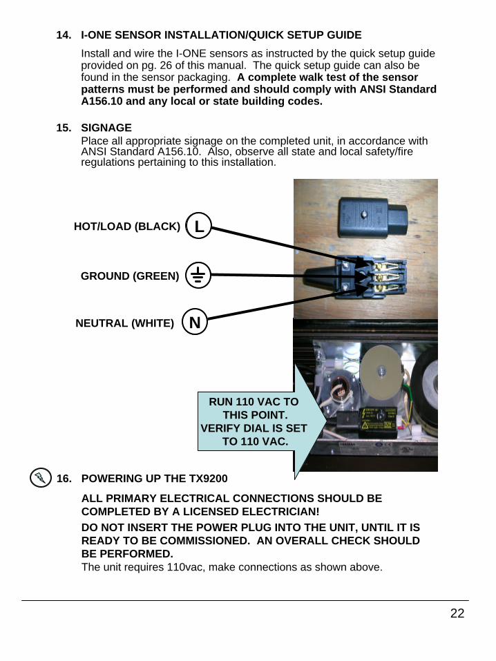
RUN 110 VAC TO THIS POINT.
VERIFY DIAL IS SET TO 110 VAC.
L
N
HOT/LOAD (BLACK)
GROUND (GREEN)
NEUTRAL (WHITE)
16. POWERING UP THE TX9200
ALL PRIMARY ELECTRICAL CONNECTIONS SHOULD BE COMPLETED BY A LICENSED ELECTRICIAN!DO NOT INSERT THE POWER PLUG INTO THE UNIT, UNTIL IT IS READY TO BE COMMISSIONED. AN OVERALL CHECK SHOULD BE PERFORMED.The unit requires 110vac, make connections as shown above.
23
17. INITIAL START UP
At this point a complete check of all fasteners, wire connections and routing, mechanical operation of both SX-panels and breakout panels, signage, and overall appearance should be performed. Apply power to the unit, switch function pad to automatic mode (position 2). The unit will begin a calibration run. If equipped with photo electric beams, be sure not to interrupt them while calibration run is being performed. If a battery back up is supplied, be sure to connect the two pin connector from the batteries to the module. This connector is disconnected during shipment to prevent damage to the unit. The batteries will require time to charge fully. The unit will automatically charge the batteries while 110v is being supplied. If access control is supplied, check for proper function of panic hardware. If an electro-mechanical lock is supplied, check for proper function. This will depend on customer preference, i.e. fail safe or fail secure, locking in off and exit modes or all modes. NOTE: If a battery backup is being used in conjunction with a lock, the main power must be removed first, then battery backup removed in order to test the fail characteristics of the lock. A complete walk test of the sensors must be performed and shouldcomply with ANSI A156.10 and any local or state building codes.

24
FINAL CHECKLIST
Y N N/ADo the doors slide freely, no binding/dragging?
Are all wires clear from moving parts?
Are all adjustment bolts tight including anti-risers?
Do the break out panels function properly with no obstructions?
Is the breakout switch functioning? (TX9300 & TX9430)
Are there any fault codes flashing on the FCP?
Are all modes on the FCP operating correctly (Off, Auto, Red Open, Exit, Hold)?
Are the holding beams operating correctly (if equipped)?
Is the lock (electrical or mechanical) functioning properly?
Has an ANSI A156.10 inspection been completed?
Are the Door# decal, Service decal, Daily Safety Check decal allpresent and in proper location?
Has the Daily Safety Check been reviewed with the Manager?
Have all the FCP functions been reviewed with the Manager?
Was the Owners manual given to the Manager?
Did the Manager sign the work order/service ticket?
Installer signature/date
25
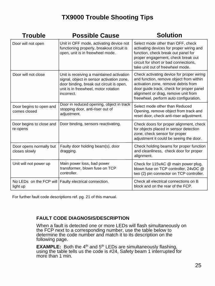
TX9000 Trouble Shooting Tips
Trouble Possible Cause SolutionDoor will not open
Door will not close
Door begins to open and comes closed
Door begins to close and re-opens
Door opens normally but closes slowly
Unit will not power up
For further fault code descriptions ref. pg. 21 of this manual.
Unit in OFF mode, activating device not functioning properly, breakout circuit is open, unit is in freewheel mode.
Select mode other than OFF, check activating devices for proper wiring and function, check break out panel for proper engagement, check break out circuit for short or bad connections, take unit out of freewheel mode.
Unit is receiving a maintained activation signal, object in sensor activation zone, door binding, break out circuit is open, unit is in freewheel, motor rotation incorrect.
Check activating device for proper wiring and function, remove object from within activation zone, remove debris from door guide track, check for proper panel alignment or drag, remove unit from freewheel, perform auto configuration.
Door in reduced opening, object in track stopping door, anti-riser out of adjustment.
Select mode other than Reduced Opening, remove object from track and reset door, check anti-riser adjustment.
Door binding, sensors reactivating. Check doors for proper alignment, check for objects placed in sensor detection zone, check sensor for proper adjustment it could be seeing the door.
Check holding beams for proper function and cleanliness, check door for proper alignment.
Faulty door holding beam(s), door dragging.
Main power loss, bad power transformer, blown fuse on TCP controller.
Check for 115vAC @ main power plug, blown fuse on TCP controller, 24vDC @ two (2) pin connector on TCP controller.
Faulty electrical connection. Check all electrical connections on B block and on the rear of the FCP.
No LEDs on the FCP will light up
FAULT CODE DIAGNOSIS/DESCRIPTION
When a fault is detected one or more LEDs will flash simultaneously on the FCP next to a corresponding number, use the table below to determine the code number and match it to its description on thefollowing page.
EXAMPLE: Both the 4th and 5th LEDs are simultaneously flashing, using the table tells us the code is #24, Safety beam 1 interrupted for more than 1 min.

26
27
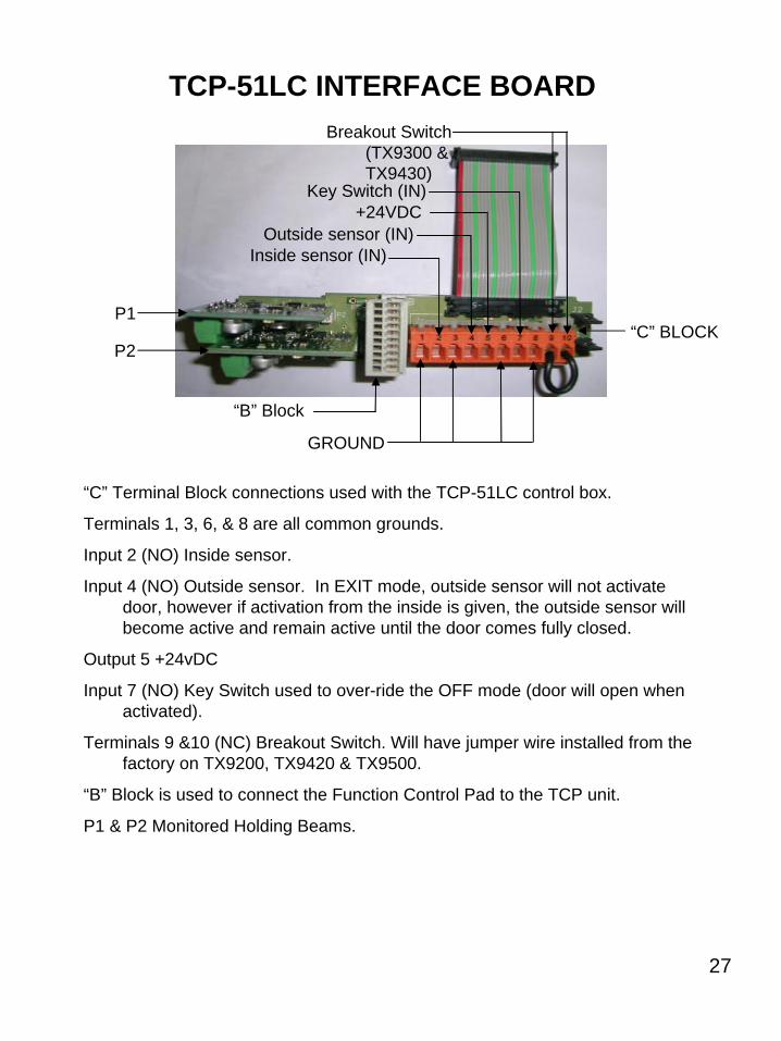
GROUND
Inside sensor (IN)Outside sensor (IN)
Key Switch (IN)
Breakout Switch (TX9300 & TX9430)
+24VDC
“C” Terminal Block connections used with the TCP-51LC control box.
Terminals 1, 3, 6, & 8 are all common grounds.
Input 2 (NO) Inside sensor.
Input 4 (NO) Outside sensor. In EXIT mode, outside sensor will not activate door, however if activation from the inside is given, the outside sensor will become active and remain active until the door comes fully closed.
Output 5 +24vDC
Input 7 (NO) Key Switch used to over-ride the OFF mode (door will open when activated).
Terminals 9 &10 (NC) Breakout Switch. Will have jumper wire installed from the factory on TX9200, TX9420 & TX9500.
“B” Block is used to connect the Function Control Pad to the TCP unit.
P1 & P2 Monitored Holding Beams.
“B” Block
P2
P1“C” BLOCK
TCP-51LC INTERFACE BOARD
28
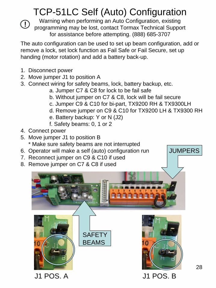
TCP-51LC Self (Auto) ConfigurationWarning when performing an Auto Configuration, existing
programming may be lost, contact Tormax Technical Support for assistance before attempting. (888) 685-3707
The auto configuration can be used to set up beam configuration, add or remove a lock, set lock function as Fail Safe or Fail Secure, set up handing (motor rotation) and add a battery back-up.
1. Disconnect power2. Move jumper J1 to position A3. Connect wiring for safety beams, lock, battery backup, etc.
a. Jumper C7 & C8 for lock to be fail safeb. Without jumper on C7 & C8, lock will be fail securec. Jumper C9 & C10 for bi-part, TX9200 RH & TX9300LHd. Remove jumper on C9 & C10 for TX9200 LH & TX9300 RHe. Battery backup: Y or N (J2)f. Safety beams: 0, 1 or 2
4. Connect power5. Move jumper J1 to position B
* Make sure safety beams are not interrupted6. Operator will make a self (auto) configuration run7. Reconnect jumper on C9 & C10 if used8. Remove jumper on C7 & C8 if used
J1 POS. A J1 POS. B
SAFETY BEAMS
JUMPERS
!
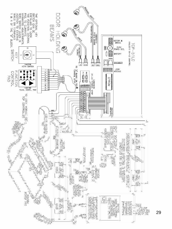
29

30
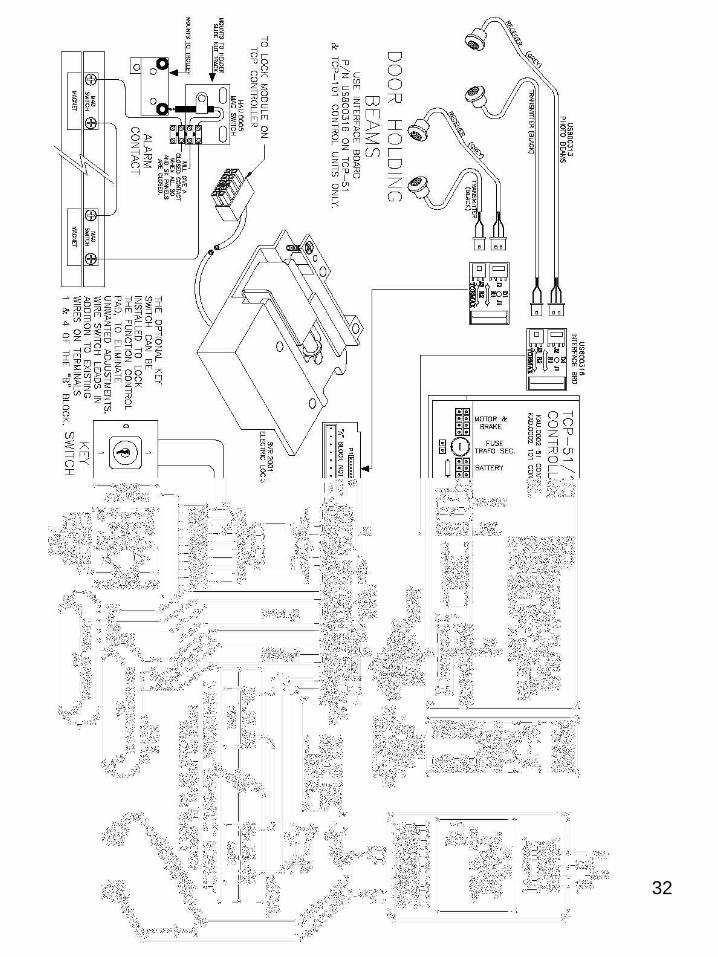
BLACKREDWHITEYELLOWBLUEGREYGREENBROWNORANGEPURPLE
“A” BLOCK NOT USED
P1 P2
Inside sensor (IN)
Outside sensor (IN)
Key Switch (IN)Breakout Switch
+24VDC
GROUND+24VDC
“C” Terminal Block connections used with the TCP-51/101 control box.
Terminals 1, 3, 6, & 8 are all common grounds.
Input 2 (NO) Inside sensor.
Input 7 (NO) Outside sensor. In EXIT mode outside sensor will not activate door, however if activation from the inside is given, the outside sensor will become active and remain active until door comes fully closed.
Outputs 5 & 10 +24vDC.
Inputs 4 & 9 Programmable per customer request.
“B” Block is used to connect the Function Control Pad to the TCP unit (connect as shown).
“D“ Block
Terminals 1 & 2 (NC) Break out Switch. Will have jumper wire installed from the factory on TX9200, TX9500 & TX9420.
Terminals 3 & 4 (NO) Key Switch Function.
P1 & P2 Monitored Holding Beams.
TCP-51 & 101 INTERFACE BOARD
“B” BLOCK
“C” BLOCK
“D” BLOCK
31
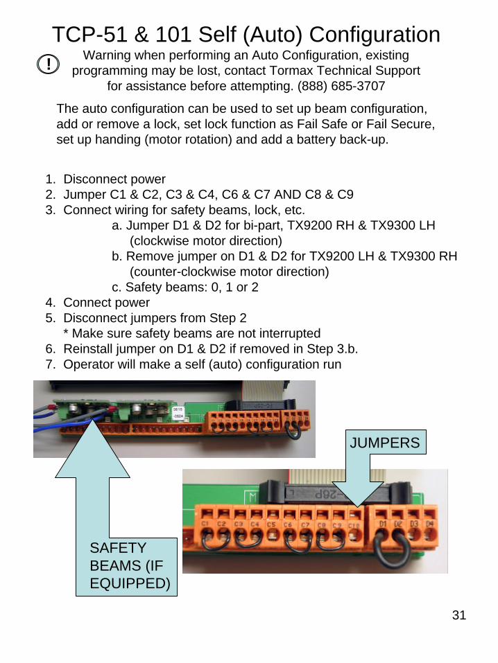
TCP-51 & 101 Self (Auto) ConfigurationWarning when performing an Auto Configuration, existing
programming may be lost, contact Tormax Technical Support for assistance before attempting. (888) 685-3707
1. Disconnect power2. Jumper C1 & C2, C3 & C4, C6 & C7 AND C8 & C93. Connect wiring for safety beams, lock, etc.
a. Jumper D1 & D2 for bi-part, TX9200 RH & TX9300 LH(clockwise motor direction)
b. Remove jumper on D1 & D2 for TX9200 LH & TX9300 RH(counter-clockwise motor direction)
c. Safety beams: 0, 1 or 24. Connect power5. Disconnect jumpers from Step 2
* Make sure safety beams are not interrupted6. Reinstall jumper on D1 & D2 if removed in Step 3.b. 7. Operator will make a self (auto) configuration run
SAFETY BEAMS (IF EQUIPPED)
JUMPERS
The auto configuration can be used to set up beam configuration,add or remove a lock, set lock function as Fail Safe or Fail Secure, set up handing (motor rotation) and add a battery back-up.
!
32

33

34

35