installation & servicing instructions & servicing instructions netaheat electronic balanced...
TRANSCRIPT

INSTALLATION & SERVICING INSTRUCTIONS
Netaheat Electronic balanced flued
gas-fired boilers
Potterton Netaheat Electronic 6/10 6 to 10 kW (20.000 to 35,000 Btu/h)
Potterton Netaheat Electronic 16/22 16 to 22 kW (55,000 to 75,000 Btu/h) Output
Potterton Netaheat Electronic 10/16 10 to 16 kW (34,000 to 55,000 Btu/h)
THIS DOCUMENT CONSISTS OF THREE PARTS:
FIRST PART - DATA SECTION
SECOND PART - INSTALLATION INSTRUCTIONS
THIRD PART - SERVICING INSTRUCTIONS
These instructions are to be followed and the specification of the appliance must not be modified
These instructions are to be left with the User or adjacent to the service meter.

IMPORTANT: THIS APPLIANCE IS FOR USE WITH NATURAL GAS ONLY.
IT MUST BE INSTALLED BY A COMPETENT PERSON AS STATED IN THE GAS SAFETY (INSTALLATION AND USE) REGULATIONS 1984
THESE BOILERS CAN BE USED ON SEALED SYSTEMS IF FITTED WITH OVERHEAT THERMOSTAT
KIT P.I.L. No. 205725 (6/10 & 10/16) OR No. 205724 (16/22)
Page 1
DATA SECTION – Page 2
The following special items are available as optional kits:-
For 6/10 Models & 10/16 Models P.I.L. No.
Pump kit casing assembly 205744

Internal fitment kit 205775
Wall Plate 205580
Terminal Guard 205792
Overheat thermostat kit 205725
Infill panel pack (single) 905813
Ducting kit*:-
*Extension Kit Concentric ducts 205890
*Extension Kit Square ducts 205754
For 16/22 Models
Pump kit casing assembly 205744
Air Duct assembly – 200620
Flue extension rear outlet only
Terminal Guard 200493
Overheat thermostat kit 205724
Infill panel pack (single) 905813
*IMPORTANT - Ducting kits must not be used on 16/22 models.
*NOTE - See Addendum 1 - Flues for flue length criteria
GENERAL
Potterton Netaheat boilers are fully automatically controlled, wall mounted balanced flue appliances, specially designed for combined gravity hot water and pumped centralheating or fully pumped systems (small bore or micro-bore) giving ease of siting, installation and servicing. The data badge is in the base of the control cover. The codebadge is on the thermostat housing.
THE SYSTEM
Potterton Netaheat boilers have been specially designed for combined systems e.g. small bore or micro-bore central heating with an indirect domestic hot water supplywhich can either have pumped or gravity circulation; the boiler can also be used for pumped central heating only. The boiler can be installed in most types of system, but thefollowing notes are given as a general guide and reference made to the following documents.

BS5376 Part 2
1976:
Code of practice for selectionand installation of gas spaceheating (1st and 2nd familygases - Boilers of rated input notexceeding 60 kW).
BS5440 Part 1
1978:
Code of practice for flues and airsupply for gas appliances ofrated input not exceeding 60 kW(1st and 2nd family gases) -Flues.
BS5440 Part 2
1976:
Code of practice for flues and. airsupply for gas appliances ofrated input not exceeding 60 kW(1st and 2nd family gases) - AirSupply.
BS5449 Part 1
1977:
Code of practice for centralheating for domestic premisesForced circulation hot watersystems.
BS5546 1979:
Code of practice for installationof gas hot water supplies fordomestic purposes (2nd familygases).
CP331 Part 3
1974:
Code of practice for low pressureinstallation pipes.
Building Regulations:
Installations in permanentdwellings. England and Scotland.
Model Water Byelaws
British Gas Publication DM2 - Guide for gas installations in timber framed housing.
First Edition September 1982
Gas Safety (Installation and Use) Regulations 1984
All pumped systems should be designed so that the static head of the boiler is between a minimum of 305mm (1 ft.) and a maximum of 27.5m (90 ft.). To ensure that theminimum 305mm (1 ft.) static head is obtained, the level of the cold water in the expansion tank must not be lower than the top of the boiler casing or the highest point in theheating system.
If a minimum 305mm (1 ft.) head is used, extra care should be taken when designing the system, to ensure that pumping over or sucking down at the vent pipe cannot occur.
All gravity domestic systems should have a minimum circulating head above the heat exchanger of 0.9m (3 ft.)
See Fig. 24.
A typical combined gravity system is shown in Fig.24.
A fully pumped system giving temperature control of the central heating circuit via a room thermostat and a two-position valve or diverter is shown in Fig. 23(a)

If temperature control is required on the hot water system, additional equipment is necessary and details are shown in Fig. 24.
For independent temperature control of both the central heating and domestic hot water circuits, a three-position valve with a central position can be used, as shown in Fig.23. This type of valve can give a flow to either circuit separately or to both circuits simultaneously. For the wiring of this type of valve refer to the valve manufacturers literatureand the information given in Section 6. Wiring.
Independent temperature control of both circuits can also be obtained by using room and cylinder thermostats and a two-position diverter valve. This valve provides a flow toone circuit at a time and details are shown in Fig. 23.
The use of two zone valves will also give independent temperature control of both circuits and details; of this type of system are also given in Fig.23(b).
A further method of providing independent temperature control in conjunction with room and cylinder thermostats, is by using two pumps. Details are given in Fig.25. Foropen systems it is recommended that an indirect cylinder with a coil type of heat exchanger is used. For sealed systems the storage vessel must be of the indirect coil typeor a direct cylinder fitted with an immersion calorifier which is suitable for the system pressure. When fitting the boiler, no system should be designed in which it is possible tocompletely close both the domestic hot water and central heating circuits, and to obtain this, a by-pass of at least 15mm Ø pipe between the boiler flow and returnconnections should be used. The by-pass circuit must include a lockshield valve and be in circuit with the pump see Fig. 23 (a), (b) & (c).
As the boilers are wall hung, a drain cock should be included at the lowest point in the central heating system. (When selecting a circulating pump for the central heatingsystem, the data contained in Fig.2 should be borne in mind). For systems requiring a low static head, close coupled feed and vent, and feed and vent connections somedistance away from the boiler Figures 19, 20 & 21 should be referred to.
Page 2
Data Section – Page 3


Fig. 1 GENERAL ARRANGEMENT
Page 3
Data Section – Page 4
Circulating Pump Selection
The resistance through the heat exchanger is equal to 25mbar (10in.w.g.) at a flow rate of 27.25 litres/min. (6galIs/min.), when using the 1 in. flow connection or 43.75mbar (17.5in.w.g.) at the same flow rate when using the ¾ in. flow connection, see Fig. 2. If other controls, such as three-position valves are used in this type of system, theresistance through them, quoted in their manufacturers literature, must be taken into account.
The circulating pump may be fitted on either the flow or return side of the boiler. If fitted on the flow, and the cold feed is taken to the return port on the boiler, the centralheating circuit will be under a positive pressure, so reducing the risk of air being drawn into the system, but if the pump is on the return there will be a negative pressure in thecircuit.
The pump can be fitted in the space above the boiler if required. Use pump casing kit P.l.L. No. 205744.
It is recommended that the static head on the inlet side of the pump should be at least a third of the maximum pump duty.
Fig. 2 PRESSURE LOSS ACROSS BOILER
The pump must be fitted with two isolating valves which are positioned as close to the pump as possible. Isolation of the valves must always leave the open vent pipeunobstructed.

The boiler can be used on a sealed system providing the overheat thermostat kit No. 205725 (6/10 & 10/16) or 205724 (16/22) is used. Fig.21 shows a typical sealedsystem, for further information refer to the literature supplied with the overheat thermostat kit.
INSTALLATION AND SITE REQUIREMENTS
Ensure that the gas supply pipe and meter are large enough for this appliance and any others that may be run off the same meter: if not, contact the local Gas Regional Office. The boiler can be installed at any height (refer to Clearances Around the Boiler and the static head requirements) on an outside wall or on an internal wall providing that oneside of the boiler is next to an outside wall. The recommendations of the British Standards Codes of Practice BS.5440 Part 1 should be followed.
Boiler Mounting Surface
The boiler must be mounted on a flat wall of non-combustible material sufficiently robust to take the weight of the boiler. The requirements of the local authorities and theBuilding Regulations must be adhered to.
IMPORTANT NOTICE: TIMBER FRAMED HOUSES
If the appliance is to be fitted in a timber framed building it should be fitted in accordance with the British Gas Publication, "Guide for Gas Installations in Timber FramedHousing" reference DM2. If in doubt, advice must be sought from the local Gas Region of British Gas.
Clearances Around the Boiler
Any position selected for the boiler must give the following minimum clearances which are necessary for installation and maintenance.
610mm (2 ft.) at the front of the boiler, 5mm (.2 in.) each side, 102mm (4 in.) at the top - except where the optional extra pump casing is to be fitted, when 178mm (7 in.), mustbe allowed.
For high level installation e.g. above working surfaces, shelves, cabinets etc, a minimum clearance of 102mm (4 ins.) is required between the bottom of the appliance andthe working surface.
For low level installations a minimum clearance of 127mm (5 ins.) is required between the bottom of the appliance and the floor. An infill panel is supplied with the boiler. Ifinstalled with one side exposed this panel covers the pipework. Extra panels are available P I L No. 905813.
It is possible to achieve installation of the boiler with the clearances specified but it is advisable during installation to provide temporary access particularly to the waterconnections at the rear of the boiler. The appliance can then be "built in" to the minimum clearance dimensions on completion of the installation.
VENTILATION

If the boiler is to be installed in a confined space such as a cupboard, the space will need ventilating. Openings must be provided at the top and bottom of the cupboard eachof which should have a free area as follows:-
If the openings draw air from outside the building, the free areas may be halved. Refer to British Standard Code of Practice BS 5440 Part 2 1976 for further guidance.
Balanced Flue Terminals and Ducting
The fresh air inlet and flue ducts can be run from either the left, right or rear of the boiler to a miniature terminal on the outside wall of the building. For information appertainingto standard flue lengths and to extension kits applications reference should be made to Addendum 1 supplied with these instructions. The siting of the balanced flue terminalon the outside wall of the building is shown in Fig.3. If a terminal is fitted less than 2m above a balcony, above the ground or above a flat roof to which people have accessthen a suitable terminal guard should be fitted, Terminal Guard P.I.L. No. 205792 (6/10 and 10/16) & P.I.L. No. 200493 (16/22).
Fig.3 Netaheat flue terminal positions
Page 4
Data Section – Page 5

Note:-
Where a flue terminal is fitted less than 850mm (34 in.) from a plastic or painted gutter or 450mm (18 in.) from painted eaves, an aluminium shield of 750mm (30 in.) length tobe fitted to underside gutter or eave.
Electricity Supply
A 240 volts ~, 50 Hz., single phase electricity supply fused to 3 amperes, must be provided in accordance with the latest edition of the Institute of Electrical EngineersRegulations for the Electrical Equipment of Buildings and Local Authorities requirements. The current rating of the wiring to the boiler must exceed 3 amperes in accordancewith BS.6500, 1975 and have a cross sectional area of at least 0.75 sq.mm. The supply to the boiler and its associated equipment should be controlled by an un-switchedplug and socket or a double pole switch (having at least 3mm contact separation) so that complete isolation from the supply can be achieved to enable maintenance work tobe carried out in safety.
FIG. 4 CONNECTIONS AND DIMENSIONS

Page 5
Data Section – Page 6
MAINTENANCE
The efficient performance of this boiler is dependent upon regular servicing which should be carried out annually.
Maintenance is best arranged by a contract placed with Potterton International Limited and further details are available from the local Potterton Regional Service Office.

All parts likely to require servicing are easily accessible. By sliding the cover from the boiler controls and removing the front cover from the boiler, most components areexposed. It is then a simple matter to remove the front of the combustion chamber to gain access to the main and pilot burners and the ignition electrode. Removal of thefluehood which is secured by four nuts, gives access to the flueways in the heat exchanger.
ADDITIONAL CONTROLS
The Potterton EP 2000/3000 time control, which is a wall-mounted electronic programmer giving a choice of programmes for both central heating and domestic hot watersystems, is available as an optional extra. The EP 2000/3000 is fully described in its own Data Sheet which is available on request.
TECHNICAL LITERATURE
The following literature is supplied with each boiler:-
Data, Installation and Service Instructions User’s Instructions
DATA
DIMENSIONS HEIGHT WIDTH DEPTH
OVERALL 872mm 400mm 310mm
(34.4 in) (15.7 in) (12 in)
SPACE FOR FIXING 1076mm 410mm 915mm High level installation
BOILER ONLY (42.4 in) (16.1 in) (36 in) over working surfaces
1102mm 410mm 915mm Low level installation
(43.4 in) (16.1 in) (36 in) Clearance at floor level
WITH PUMP KIT 1279mm
CASING ASSEMBLY (50.4 in)
WEIGHT OF THE 70kg (154 lbs) installed
APPLIANCE 54kg (119 lbs) lift weight
FLUE/AIR 6/10 & 10/16 16/22
DUCT SIZE 102mm 202 x 95.5mm
(4 in) (7.9 x 2.8 in)
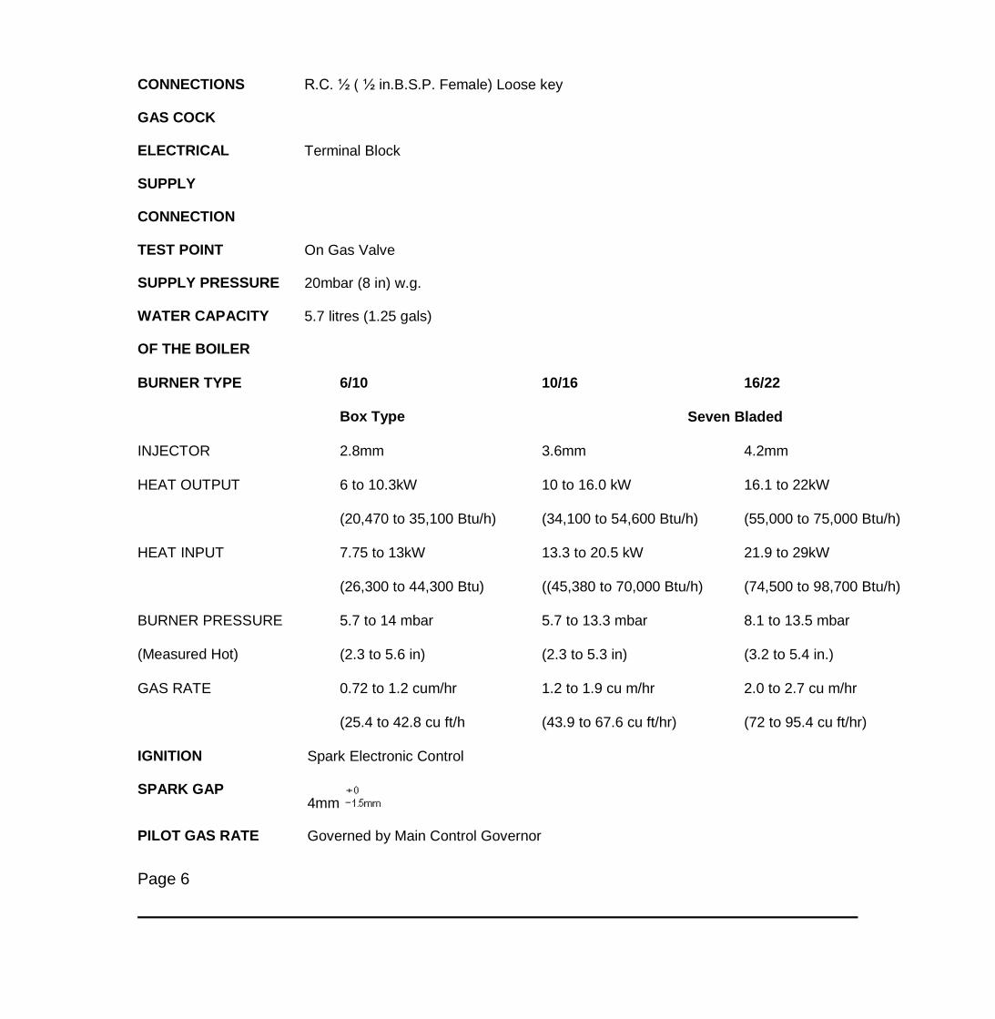
CONNECTIONS R.C. ½ ( ½ in.B.S.P. Female) Loose key
GAS COCK
ELECTRICAL Terminal Block
SUPPLY
CONNECTION
TEST POINT On Gas Valve
SUPPLY PRESSURE 20mbar (8 in) w.g.
WATER CAPACITY 5.7 litres (1.25 gals)
OF THE BOILER
BURNER TYPE 6/10
Box Type
10/16 16/22
Seven Bladed
INJECTOR 2.8mm 3.6mm 4.2mm
HEAT OUTPUT 6 to 10.3kW 10 to 16.0 kW 16.1 to 22kW
(20,470 to 35,100 Btu/h) (34,100 to 54,600 Btu/h) (55,000 to 75,000 Btu/h)
HEAT INPUT 7.75 to 13kW 13.3 to 20.5 kW 21.9 to 29kW
(26,300 to 44,300 Btu) ((45,380 to 70,000 Btu/h) (74,500 to 98,700 Btu/h)
BURNER PRESSURE
(Measured Hot)
5.7 to 14 mbar 5.7 to 13.3 mbar 8.1 to 13.5 mbar
(2.3 to 5.6 in) (2.3 to 5.3 in) (3.2 to 5.4 in.)
GAS RATE 0.72 to 1.2 cum/hr 1.2 to 1.9 cu m/hr 2.0 to 2.7 cu m/hr
(25.4 to 42.8 cu ft/h (43.9 to 67.6 cu ft/hr) (72 to 95.4 cu ft/hr)
IGNITION Spark Electronic Control
SPARK GAP 4mm
PILOT GAS RATE Governed by Main Control Governor
Page 6

INSTALLATION INSTRUCTIONS – Page 7
NOTE: When handling the boiler care must be taken to prevent damage to components situated on the base of the appliance.
1. GENERAL
Installation must be carried out in accordance with the relevant British Standard Codes of Practice and I.E.E. recommendations. If this boiler is installed in a bathroom thespecial electrical safety l.E.E. recommendations must be adhered to. Reference should also be made to British Gas publication "Material and Installation Specifications forDomestic Central Heating and Hot Water".
If the boiler is to be installed in a timber framed house the guidelines given in British Gas Publication DM2 should be followed.
The boiler and its associated equipment will arrive on site in two cardboard cartons. The contents of each carton is as follows.
CARTON No.1
1. Installation/Servicing and User’s Instructions
2. Template
3. Accessories Pack
4. Balanced flue terminal and ducts
5. Boiler Combustion chamber front cover
6. The controls cover
7. Mounting channel with rubber strip, and metal bearing plate, adjusting shims and retaining strap.
8. Telescopic trunking, Duct sealing flange and gaskets - 16/22 only (Air Duct).
9. The boiler front cover
10. Flue/air ducts, ducting gaskets (6/10 & 10/16)
All items in Carton No.1 are packed so that they are easily removable in the sequence required.
CARTON No.2:
The boiler is packed on its back. The boiler will be supplied without its combustion chamber front cover fitted so giving a hand hold at the underside of the heat exchangerinside the combustion chamber, when lifting the boiler into position. The polystyrene protective cover and the two metal feet attached to the bottom of the boiler are to protectthe controls during handling and installing the boiler ont

o the wall. These items should not be removed until the boiler is mounted on the wall. This pack also contains one infillpanel, packed under the boiler pallet.
2. FITTING THE BOILER MOUNTING CHANNEL
NOTE: The cardboard template has been designed for marking out the wall for boilers with either rear or a side flue outlet. When positioning the template it must beremembered that a minimum of 5mm ( ¼ in.) clearance must be provided between the boiler and any side wall. Allowance should be made if the corners of the wall are notsquare or vertical and the template position adjusted accordingly.
If a side outlet is to be used on a 16/22 boiler the distance between the boiler and the outside wall must not be greater than 20mm ( ¾ in.). Reference should be made toAddendum 1, Flue Lengths Criteria.
NOTE: If the square ducts flue extension kit is used, the template provided with the boiler should be discarded and the template supplied with the kit used.
A. Using the template, mark out the three screw holes on the wall where the boiler mounting channel is to be positioned, the four screw holes above the mounting channelwhere the plenum chamber is to be fitted, and the position of the flue and fresh air ducts on the wall.
B. Drill the three holes for the mounting channel securing screws and insert wallplugs (Accessories Pack Item A): fit and secure the channel using the 51mm (2 in) No.12counter sunk headed woodscrews, cup and flat washers: check that the channel is level Place three of the six metal adjusting shims in the mounting channel followed by therubber strip, then the metal bearing plate. Retain the remaining three shims.
NOTE: The thickness of the wall plaster in some properties could be excessive and in these instances it is recommended that 64mm (2½ in) long securing screws are usedin operation B. When fitting on to dry lined walls ensure that a sound fixing is achieved.
C. Drill the four holes for the plenum chamber securing screws and insert wallplugs (Accessories Pack Item B); do not fit the plenum chamber at this stage.
If the internal fitment kit Part No.205775 is used drill a 102mm dia. (4 in.) hole using a core bit.
D. Cut the hole in the wall for the flue and fresh air ducts. Care should be taken when cutting the hole for a rear outlet boiler, that the screw holes for the plenum chamber arenot damaged. Make good the inside and outside surface of the wall, if necessary, and also ensure that the face of the wall where the plenum chamber is to be fitted is flat.
E. Open Carton No.2.
NOTE: If an overheat thermostat is to be fitted it is recommended that it is fitted at this stage, see kit literature.

F. Unscrew and remove the nuts securing the flue-hood, then lift off the fluehood, see. Fig. 9 Discard the paper gasket.
G. Disconnect the three electrical leads from the fan, then unscrew and remove the screws securing the fan. Lift off the fan, see Fig. 9.
H. Unscrew and remove the screws securing the plenum chamber, see Fig. 9.
J. Remove the boiler from its carton and lay it front face downwards on a protective surface, such as its own carton. Take care not to damage the spindle of the thermostat, orthe capillary. Remove infill panel.
3.A FITTING THE DUCTING, PLENUM CHAMBER AND B.F. TERMINAL 6/10 AND 10/16
1. The plenum chamber is designed to accept the 6/10 & 10/16 air/flue duct assembly from either side and from the rear. If flue extension ducts Kit No. 205890 1067mm (42in.) is required discard the standard air/flue ducts and replace with ducts from kit for flue extensions between 1036mm (41 in) and 1880mm (74 in) a special kit is availableKit No. 205754. For installation of this Kit the instructions provided with it must be adhered to.
The side outlets of the plenum chamber have been sealed by blanking plates and gaskets. To use either of the side outlets it will be necessary to remove both the inner andouter blanking plates and gaskets from the side required for discharge. Both of these blanking plates and gaskets must then be fitted to the rear outlet of the plenum boxbefore proceeding further. It is very important that the inner plate is properly refitted.
Page 7
Installation Instructions – Page 8
2. Air/Flue Duct Assembly
i) Take the smaller flue duct and larger air duct from pack 1.
ii) Measure the wall thickness accurately.
iii) For Rear Outlet
a) Select the smaller flue duct and ‘Mark OFF’ (at the plain end) the cutting dimension which is equal to: The wall thickness plus 73mm (2.9 in.).
b) Cut the tube square to the mark and remove all burrs and sharp edges.
c) Select the larger air duct and ‘Mark OFF’ (at the plain end) the cutting dimension which is equal to: The wall thickness plus 33mm (1.3 in.)

d) Cut the tube square to the mark and remove all burrs and sharp edges.
iv) For Side Outlet
a) Select the smaller flue duct and mark ‘OFF’ (at plain end) the cutting dimension which is equal to: The wall thickness plus the distance between the boiler casing and thewall plus 187mm (7.4 in.).
b) Cut the tube square to the mark and remove all burrs and sharp edges.
c) Select the larger air duct and mark ‘OFF’ (at the plain end) the cutting dimension which is equal to: The wall thickness plus the distance between the boiler casing and thewall plus 148mm (5.8 in.).
d) Cut the tube square to the mark and remove all burrs and sharp edges.
v) Fit the air and flue ducts to the plenum chamber using the gaskets and screws from Pack C. Fig. 5.
vi) Locate the ends of both ducts into the terminal rotate the terminal so that the deflector vanes deflect products away from surfaces or obstructions on the external surface ofthe wall. Use a 2mm
Fig. 6 RELATIVE POSITION OF PLENUM CHAMBER AND MOUNTING CHANNEL
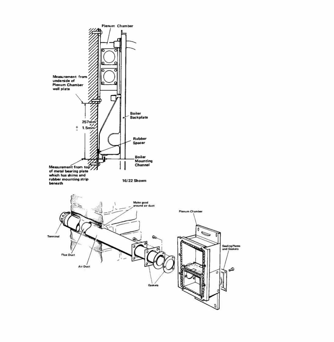

Fig. 5 ARRANGEMENT OF NETAHEAT 10/16 AND 6/10 ONLY
Page 8
Installation Instructions – Page 9
drill and drill through the pre-drilled holes in the terminal casting and secure with screws provided in pack H.
3. For rear outlet flues, slide the glass fibre rope seal onto the terminal and push into position against the plenum chamber. For side outlet flues the glass fibre rope seal canbe discarded.
4. Secure the plenum chamber/flue assembly to the wall using the four 51mm (2 in.) No.12 counter sunk headed screws, cup and flat washers (Pack B).
NOTE: The thickness of the wall plaster in some older properties could be excessive and in these instances, it is recommended that 64mm (2 ½ in) long screws are used.When fitting on to dry lined walls ensure that a sound fixing is achieved.
5. Measure the distance from the bottom of the plenum chamber wall plate to the top of the metal bearing plate in the boiler mounting channel, see Fig.6. Compare thisdimension with the nominal dimension of 257mm (10 ins.) and by adding additional shims or removing those already in position, adjust the measured distance to equal thenominal measurement ± 1.5mm (1/16 in.). If a more coarse adjustment is necessary, the plenum chamber and mounting channel can be moved slightly up or down on the wallusing the elongated holes in their mounting flanges. It is essential that this dimension is accurately obtained, otherwise once the boiler is lifted onto its mounting channel, thescrew holes in the boiler back plate will not align with those in the plenum chamber.
6. Make good the outside wall surfaces around the flue outlet. A terminal wall plate Potterton Part No. 205580 is available to improve the wall appearance around the terminal.
7. For side outlet flues the internal wall should also be made good around the terminal tube
8. If the height of the terminal from the ground or balcony level is less than 2m a terminal guard must be fitted Potterton Part No. 205792, 6/10 & 10/16, Potterton Part No.200493, 16/22.
3.B. Potterton Netaheat 16-22 only - See Fig.7
1. The plenum chamber has two connections for the fresh air and flue ducts, one to one side and the other to the rear. The rear connection is blanked off with a sealing plate,gasket and heat shield. Depending on the direction the ducts are to be connected to the boiler, these should be re-positioned by the installer if necessary. The single sideconnection can be used either for a left or right-hand duct arrangement, simply by rotating the plenum chamber to the required position. With a rear outlet, the smaller openingin the plenum chamber (air duct) must be positioned uppermost. The heat shield is only required for side outlet and should be discarded when the rear outlet is used.

2. Fit the inlet and outlet duct assembly to the plenum chamber using the eight screws (Accessories pack Item C) and interposing the gasket. Ensure that the short air duct ispositioned uppermost.
3. Temporarily secure the plenum chamber to the wall using the four 51mm (2 in.) No.12 screws, cup and flat washers (Accessories pack Item B) positioning the flue andfresh air ducts through the wall.
4. Mark off the lower flue duct at a point where it protrudes 32mm (1.3 in.) from the outside wall of the building.
5. The upper air duct is already sized to suit wall thicknesses between 230 mm and 406 mm (9 to 16 in.) and will only need shortening, if the wall
Fig. 7 ARRANGEMENT OF NETAHEAT 16/22 DUCTS
Page 9
Installation Instructions – Page 10
is less than 230mm (9 in.) thick. In this instance cut off the nozzle end of the upper duct so that not less than 25mm (1 in.) and not more than 50mm (2 in.) protrudes inside thewall.
6. Remove the plenum chamber, then cut the duct(s) to size, removing all burrs and taking care not to distort the circularity of the duct(s).

7. Adjust the telescopic trunking so that the overall dimension equals the thicknessof the wall. Seal the joint line of the trunking with the sealing tape provided. For rear outletonly the telescopic trunking can be extended to a wall thickness of 540 mm (21 in.) Use Potterton Part No. 200620.
8. Fit the telescopic trunking inside the wall and secure it to the inside face of the wall with two 38mm (1½ in.) No.8 screws, washers and wall-plugs (Accessories pack Item D).
NOTE: If the wall is less than 230mm (9 in.) thick both halves of the telescopic trunking will have to be cut to the size at the plain ends where the two halves slide together; e.g. for a 180mm (7 in.) wall, cut 50mm (2 in.) from each half.
9. Secure the duct sealing flange and rubber gasket see Fig.7, to the telescopic trunking using the six screws (Accessories pack item D).
10. Position the ducts inside the wall, then secure the plenum chamber to the wall with four 51mm (2 in.) No.12 screws, cup and flat washers (Accessories pack Item B).Ensure the chamber is mounted squarely.
NOTE: The thickness of the wall plaster in some older properties could be excessive and in these instances, it is recommended that 64mm (2 ½ in.) long securing screwsare used. When fitting on dry lined walls, ensure that a sound fixing is achieved.
11. Measure the distance from the bottom of the plenum chamber wall plate to the top of the metal bearing plate in the boiler mounting channel, see Fig.6. Compare thisdimension with the nominal dimension of 257mm (10.1/8 in,) and by adding additional shims or removing those already in position, adjust the measured distance to equalthe nominal measurement, + 1.5mm (1/16 in.). If a more coarse adjustment is necessary, the plenum chamber and mounting channel can be moved slightly up or down on thewall using the elongated holes in their mounting flanges. It is essential that this dimension is accurately obtained otherwise once the boiler is lifted onto its mounting channel,the screw holes in the boiler back-plate will not align with those in the plenum chamber.
12. Make good the inside and outside surface of the wall around the telescopic trunking. Ensure that the flue outlet duct protrudes from the trunking in the CENTRE of thesquare aperture. This is essential to enable the next operation to be completed.
13. Fit the terminal outer wall plate in position, locating the end of the exhaust duct inside the circular connection of the wall plate grille. Loosely attach the plate to the trunk ingwith the single M5 screw (Accessories pack Item E).
14. Square up the wall plate, then working through the four screw holes in the plate, mark the screw hole positions on the wall behind the plate.

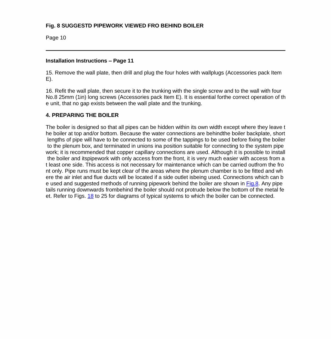
Fig. 8 SUGGESTD PIPEWORK VIEWED FRO BEHIND BOILER
Page 10
Installation Instructions – Page 11
15. Remove the wall plate, then drill and plug the four holes with wallplugs (Accessories pack Item E).
16. Refit the wall plate, then secure it to the trunking with the single screw and to the wall with four No.8 25mm (1in) long screws (Accessories pack Item E). It is essential forthe correct operation of the unit, that no gap exists between the wall plate and the trunking.
4. PREPARING THE BOILER
The boiler is designed so that all pipes can be hidden within its own width except where they leave the boiler at top and/or bottom. Because the water connections are behindthe boiler backplate, short lengths of pipe will have to be connected to some of the tappings to be used before fixing the boiler to the plenum box, and terminated in unions ina position suitable for connecting to the system pipework; it is recommended that copper capillary connections are used. Although it is possible to install the boiler and itspipework with only access from the front, it is very much easier with access from at least one side. This access is not necessary for maintenance which can be carried outfrom the front only. Pipe runs must be kept clear of the areas where the plenum chamber is to be fitted and where the air inlet and flue ducts will be located if a side outlet isbeing used. Connections which can be used and suggested methods of running pipework behind the boiler are shown in Fig.8. Any pipe tails running downwards frombehind the boiler should not protrude below the bottom of the metal feet. Refer to Figs. 18 to 25 for diagrams of typical systems to which the boiler can be connected.
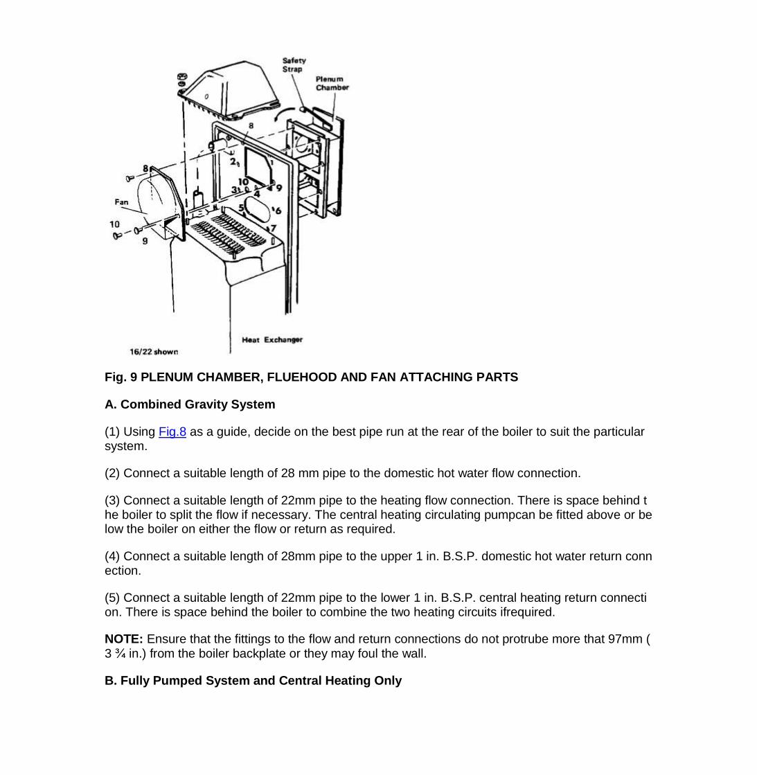
Fig. 9 PLENUM CHAMBER, FLUEHOOD AND FAN ATTACHING PARTS
A. Combined Gravity System
(1) Using Fig.8 as a guide, decide on the best pipe run at the rear of the boiler to suit the particular system.
(2) Connect a suitable length of 28 mm pipe to the domestic hot water flow connection.
(3) Connect a suitable length of 22mm pipe to the heating flow connection. There is space behind the boiler to split the flow if necessary. The central heating circulating pumpcan be fitted above or below the boiler on either the flow or return as required.
(4) Connect a suitable length of 28mm pipe to the upper 1 in. B.S.P. domestic hot water return connection.
(5) Connect a suitable length of 22mm pipe to the lower 1 in. B.S.P. central heating return connection. There is space behind the boiler to combine the two heating circuits ifrequired.
NOTE: Ensure that the fittings to the flow and return connections do not protrube more that 97mm (3 ¾ in.) from the boiler backplate or they may foul the wall.
B. Fully Pumped System and Central Heating Only

(1) Using Fig.8 as a guide, decide on the best pipe run at the rear of the boiler to suit the particular system.
(2) When connecting the flow pipework, it is only necessary to use one flow connection, preferably the upper 1 in. BSP with the lower ¾ in. BSP connection being blanked off.However, in certain circumstances where a lefthand flue terminal is being used and only a pipe run to low level is required, the lower ¾ in. BSP connection can be utilised,provided the 1 in. BSP connection is vented. Connect a suitable length of pipe to which ever connection is to be used.
(3) Connect a suitable length of 22mm pipe to the lower 1 in. B.S.P. return connection. The upper 1 in. B.S.P. return connection can either be blanked off or used to connectthe cold feed.
NOTE: On systems requiring a high flow rate, the 22mm pipework from the flow and return connections should be enlarged as close to the boiler as practicable.
(4) The circulating pump can be fitted on either the return or flow in any position to suit the particular installation.
Boiler Main Gas Cock
(1) Access can be gained to the gas service cock union with the control panel in the lowered position.
(2) When installed with minimum clearances the gas supply pipework should be installed before mounting the boiler. Prepare a ½ B.S.P. gas point terminating with the gasservice cock (provided) to the dimensions shown in Fig. 4.
Page 11
Installation Instructions – Page 12
Fig. 10 PRINCIPLE OF WIRING
5. FITTING THE BOILER ON THE WALL - See Fig.9

A metal safety strap is provided with this boiler which is used to hold the boiler backplate against the plenum chamber once the boiler has been lifted into position but beforeany plenum chamber securing bolts have been fitted.
This will enable the installer to leave the boiler unsupported once it has been positioned, so enabling him to pick up a screwdriver etc.
The strap must first be positioned by hooking it in the slot in the plenum chamber (See Fig. 9). It can then be hinged upwards against the wall until the boiler has been fittedwhen it can be hinged downwards, so holding the backplate against the plenum chamber.
NOTE: Before fitting the boiler ensure that the rubber spacer is in position, see Fig.6.
A. Stand the boiler on the floor in a vertical position using the two metal feet and polystyrene control cover protector, then using the cast iron flow pipe and the underside ofthe heat exchanger, lift the boiler into position on the wall, locating its mounting bracket on the bearing plate in the mounting channel. Support the boiler in this position usingthe safety strap if necessary then secure the boiler backplate to the plenum chamber with the screws numbered 1 to 7 on Fig. 9.
NOTE: Screw No.4 not used on 6/10 & 10/16 boilers. Three screw holes in the boiler backplate are marked with a ring and these are for use when fitting the fan and mustnot be used in this operation.
WARNING: When fitting the screws in A, the weight of the boiler could distort the boiler support bracket so making it difficult to line up the screw holes in the boiler backplatewith those in the plenum chamber, if this should occur, the weight of the boiler should be supported until the screws are correctly engaged.
B. Fit the fan in position and secure it to the boiler backplate with the three screws, numbered 8 to 10 on Fig. 9. Connect the two mains electrical leads to their connectionson the boiler backplate and the earth lead to the earth screw also on the back plate.
WARNING: It is very important that when tightening the screws in operations A and B that good seals are made. All screws must be tight.
C. Refit the fluehood to the heat exchanger, ensuring that a good seal is made at the plenum and that all the plenum fixing screws have been fitted and are tight. Secure thehood in position with the four nuts and washers; ensure the nuts are tight, and that the hood makes a good seal with the heat exchanger.
D. Fit the combustion chamber front cover, securing it with the four screws (Accessories pack Item F).
E. Remove and discard polystyrene cover.
F. Unscrew the nuts and remove and discard the two metal feet.
Undo the two screws securing the controls panel in position, then hinge down the panel to give access to the gas cock

G. Connect the main gas cock union to the boiler.
H. Connect the short lengths of pipe previously fitted to the boiler, to the system pipework, then fill and vent the water system and test for leaks. Rectify if necessary.
6. WIRINGS-See Figs. 10, 11, 12and 13
THIS APPLIANCE MUST BE EARTHED
The installation must comply with I.E.E. Wiring Regulations and any local regulations. All cable and connections must be of the approved type.
The boiler and all external control circuit wiring must be supplied from the same single isolating switch or plug and socket.
Care must be taken to ensure that all wiring to the boiler is kept clear of sharp edges and hot surfaces. The boiler terminal strip situated in the control panel is not designed toaccept wiring from all the on-site system controls and therefore, the installer will usually need to incorporate a suitable junction box or Potterton EP 2000/3000 Programmer.
The principle of wiring up the boiler and site controls is shown in Fig. 10. However, the layout of a particular system will itself govern the most economical location for thejunction box and its terminals. Wire up the boiler and system controls as illustrated in Figs. 14, 15, 16 and 17 depending on the type of system installed. The wiringarrangements shown outline only the basic control requirements, and will therefore require on-site interpretation of the various boiler installation requirements.
If a Potterton EP 2000/3000 time control is not being fitted, but a three terminal time clock is to be installed to control the systems illustrated in Figs. 14, 15, 16 and 17 thetime clock should be wired as follows:-
Live to Time Clock Live Neutral to Time Clock Neutral Earth to Time Clock Earth Wires normally connected to EP 2000/3000 terminals to time clock switch.
A frost protection (low limit) thermostat can be installed to over-ride the "OFF" setting of the time control if the temperature where the thermostat is situated, falls below thethermostat setting. Where an EP 2000/3000 Programmer is installed, a double pole or double outlet thermostat may be necessary; for the electrical connections and typerequired, see the relevant system wiring diagram. Where only a time clock is fitted, the thermostat need only be a single pole type with its contact wired in parallel with theclock switch. Feed the supply cable through the cable clamp on the rear of the control panel leaving sufficient length of cable to reach connection on the terminal block. Lift thecontrol and secure into position. Feed cable through the hole in the panel and connect to the boiler terminal strip as follows:-
6/10 and 10/16 BOILERS
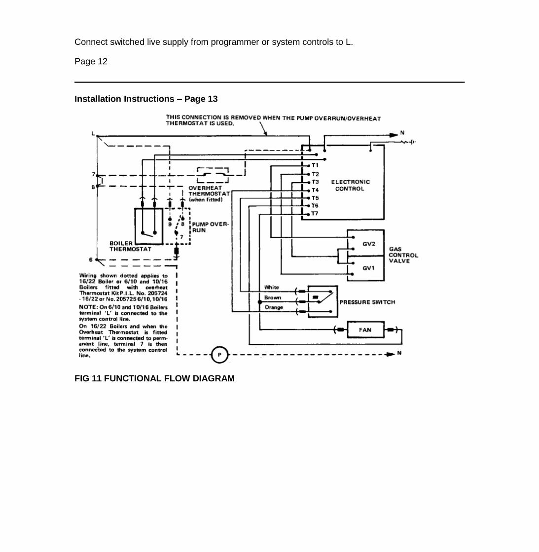
Connect switched live supply from programmer or system controls to L.
Page 12
Installation Instructions – Page 13
FIG 11 FUNCTIONAL FLOW DIAGRAM
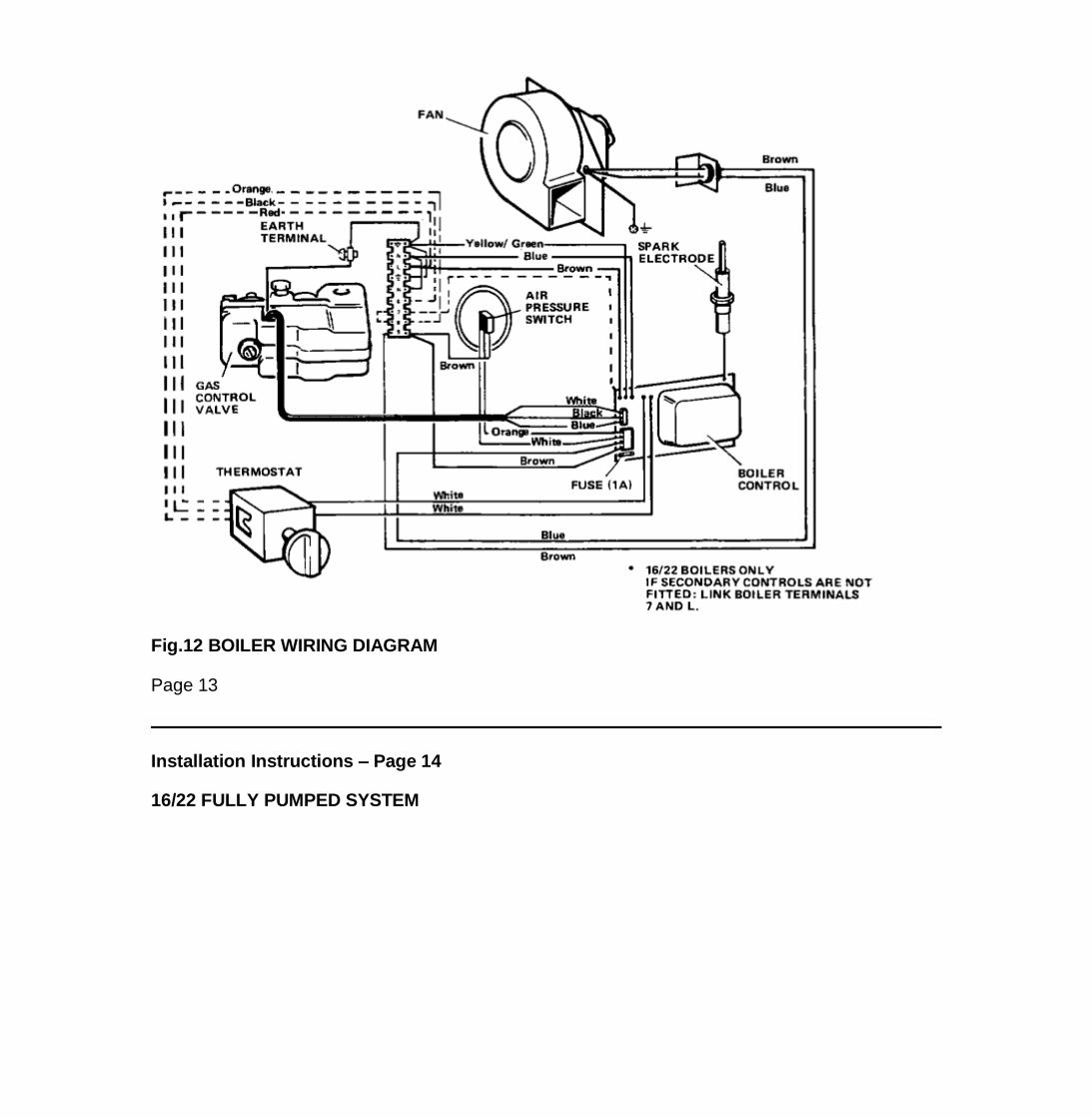
Fig.12 BOILER WIRING DIAGRAM
Page 13
Installation Instructions – Page 14
16/22 FULLY PUMPED SYSTEM

Fig 13 EXTERNAL WIRING (Boiler Terminals
16/22 BOILERS (Gravity hot water, pumped central heating)
Connect switched live supply from programmer or system controls to 7.
16/22 BOILERS (Fully pumped systems)
Connect switched live supply from programmer or system controls to 7. Connect a permanent live supply to L. Connect terminals 7 and 8 and connect the live supply to thepump to terminal 6. If no switched supply is provided link terminals 7 and L..
When all wiring is complete, hinge down the controls panel to gain access to the gas valve pressure test nipple and pressure adjuster. Fit the front cover to the boiler,securing it with the four captive screws.
Ensure that a good seal is obtained around the perimeter of the cover. Fit the thermostat knob (Accessones pack Item G). Fit infill panel if required.
To Fit the Infill Panel
Locate the notched brackets on the infill panel onto the two spring clips provided on either side of the rear face of the boiler back panel.
With the infill panel resting in position press the top of the panel firmly downwards. This will allow the notched brackets to engage fully into the spring clips. If a second infillpanel is required this can be obtained as an optional extra P.l.L. No.905813.
FIG 14 GRAVITY HOT WATER WITH PUMPED CENTRAL HEATING

EP2000/3000 PROGRAMMER SHOWN
FIG 15 GRAVITY HOT WATER WITH TEMPERATURE CONTROL AND PUMPED CENTRAL HEATING
EP 2000/3000 PROGRAMMER SHOWN
Page 14
Installation Instructions – Page 15

FIG. 16 FULLY PUMPED USING 2 MOTORISED VALVES
FIG 17 NETAHEAT WIRING MID POSITION DIVERTER VALVE (SPRING RETURN)
C = Common, NC = Normally closed
No = Normally open

The colour coding of the electrical cable fitted to the motorised valve varies from manufacturer to manufacturer. The colours indicated cover most springreturn valves. This diagram is not suitable for users which use a relay junction box.
Dotted wires show wiring for 16/22 boiler
FIG 18 FULLY PUMPED SYSTEMS
Page 15
Installation Instructions – Page 16
FIG. 19 FULLY PUMPED SYSTEMS

7. COMMISSIONING
The whole of the gas installation including the meter should be inspected and tested for soundness and purged in accordance with the recommendations of C.P. 331 Part 3.
FIRST LIGHTING
WARNING:
BEFORE LIGHTING THE BOILER. ENSURE THAT THE FRONTCOVER HAS BEEN CORRECTLY FITTED AND THAT THE EDGE OF THE COVER MAKES ATIGHT SEAL WITH THE SEALING STRIP IN THE GROOVE AROUND THE BOILER BACKPLATE.
BEFORE PROCEEDING TO LIGHT THE BOILER THE WHOLE SYSTEM SHOULD BE FLUSHED OUT WITH COLD WATER AND WITH THE PUMP REMOVED,REPLACE PUMP WHEN COMPLETED.
FOR SEALED SYSTEMS REFER TO THE INSTRUCTIONS SUPPLIED WITH THE OVERHEAT THERMOSTAT KIT.
A. Check that the main electricity supply to the boiler is switched off and that the boiler thermostat is in the off position.

B. Turn on the main gas supply.
C. Ensure that the system is full of water and that the pump and radiator isolating valves are open.
D. Ensure that the time control, if fitted is in an on condition, and that the room and/or cylinder thermostats, where fitted, are set to high temperatures.
E. Switch on the main electricity supply to the boiler.
In the event of an electrical fault after installation of the appliance, preliminary electrical system checks must be carried out (i.e. earth continuity polarity and resistance to earthas described in the multimeter instruction book). Refer to fault Finding Chart. Fig. Nos 31, 32, & 33,
FIG 20 FULLY PUMPED SYSTEMS
Close-coupled open vent and cold feed arrangements.
F. Fit the thermostat knob and turn the boiler thermostat on and to a high setting and after a period of time the main burner will light, which can be observed through the sightglass in the front cover of the boiler. The time period can vary upwards of 45 seconds, depending on the amount of air in the pipework.
Test for gas soundness around boiler components using leak detection fluid.
G. Turn off the boiler thermostat.
NOTE: There could be a delay in lighting if the control knob is switched on and off and then on again rapidly.
8. SETTING AND CHECKING OF CONTROLS
A. Gas Rate and Main Burner Pressure Setting
(1) Fit a pressure gauge to the pressure test nipple in the multi-functional control.
(2) Turn on the boiler thermostat and ensure that the main burner is alight then check that the burner pressure is in accordance with values stated under data.
The burner pressure is set to the maximum output at the factory.
(3) If burner pressure adjustment is necessary remove the screwed cap from the multi-functional control see Fig. 1 and turn the screw beneath clockwise to increase pressureor anti-clockwise to decrease. Refit the screwed cap when the pressure is correct. Shut down the boiler, remove the pressure guage and refit the screw in the pressure testnipple ensuring that a gas tight seal is made.
Page 16
Installation Instructions – Page 17
FIG. 21 SEALED SYSTEMS - Only applicable to boilers fitted with the optional over heat thermostat kit
NOTE
1 Automatic air release valves must be fitted at all high points
2 The boiler must be fitted with a safety valve pre-set to operate at 3 bar and fitted with a discharge pipe terminating at a safe and convenient position.
3 A pressure gauge, with a range of at least 0 - 4 bar, shall be fitted to the system in a visible position.
4 A filling point shall be provided at low level and fitted with a stop cock. The method adopted for filling the system shall be approved by the local WaterAuthority. Provision shall be made for replacing system water losses by the use of a makeup vessel fitted above the highest point of the system, or by thepre-pressurisation of the system.
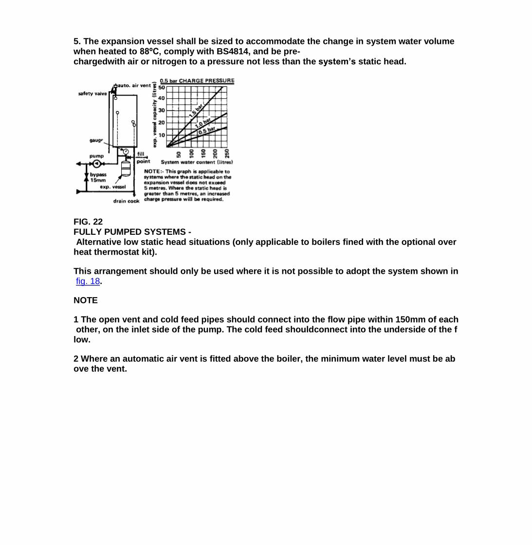
5. The expansion vessel shall be sized to accommodate the change in system water volume when heated to 88ºC, comply with BS4814, and be pre-chargedwith air or nitrogen to a pressure not less than the system’s static head.
FIG. 22 FULLY PUMPED SYSTEMS - Alternative low static head situations (only applicable to boilers fined with the optional over heat thermostat kit).
This arrangement should only be used where it is not possible to adopt the system shown in fig. 18.
NOTE
1 The open vent and cold feed pipes should connect into the flow pipe within 150mm of each other, on the inlet side of the pump. The cold feed shouldconnect into the underside of the flow.
2 Where an automatic air vent is fitted above the boiler, the minimum water level must be above the vent.

FIG 23 TYPICAL CONTROL SYSTEMS
NOTE: All 16/22 boiler systems and 6/10, 10/16 boiler systems where the overheat thermostat kit is fitted must include a by-pass circuit capable of maintaining awater flow of at least 1 gal/min, if the design permits the closing down of both hot water and central heating circuits.

FIG. 24 GRAVITY HOT WATER SYSTEMS
Page 17
Installation Instructions – Page 18
FIG. 25 FULLY PUMPED SYSTEMS USING TWO PUMPS
(e.g. conversion of existing gravity system to pumped)

(4) Isolate the main electrical supply to the boiler, raise control panel and secure into position (two screws).
(5) Remove the thermostat knob, then slide on the controls cover and secure it with the (Pack G) screw, and insert plastic plug.
(6) Refit the thermostat knob, then switch on the main electrical supply to the boiler.
(7) With the burner set to its correct pressure, the gas rate given in "Data" should also be obtained and this should be checked by meter reading over a period of at least 5minutes once the boiler is hot.
(8) The whole system should be further flushed while hot, and the lockshield valve on the by-pass circuit set for quiet operation (1 gal/min min flow rate) before leaving theinstallation.
(9) Attach self adhesive arrow to indicate burner pressure on data badge. (Pack G)
B. Pilot Burner
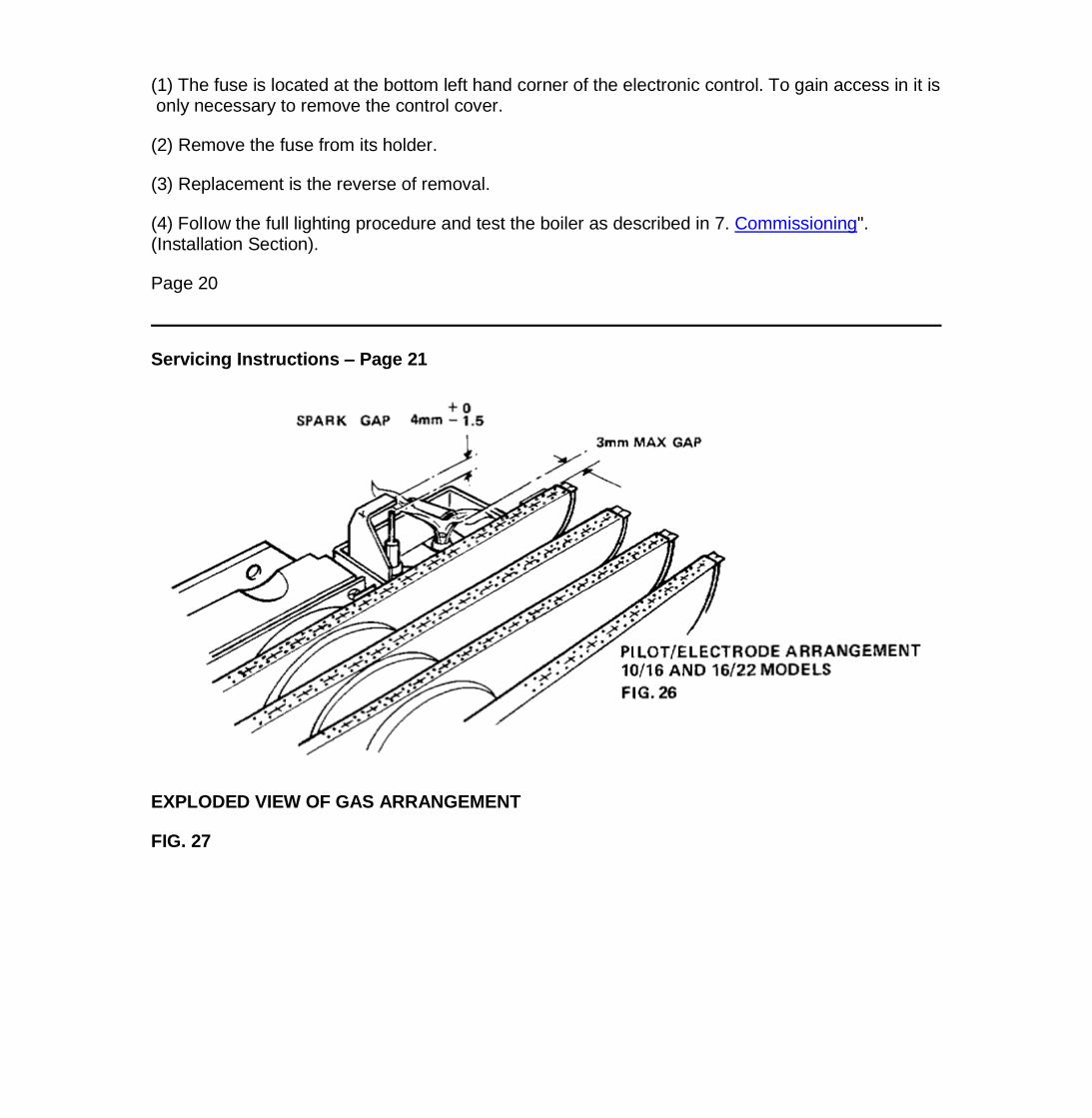
(1) The pilot is pre-set and no adjustment is required or available. The pilot flame envelope should cover the electrode tip and earth strip see Figs. 26 and 29.
C. Boiler Thermostat

(1) At its maximum and minimum settings, the thermostat should control the water flow temperature at approximately 55ºC - 82ºC (130ºF - 180ºF).
(2) The thermostat has been calibrated by the makers and no attempt should be made to re-calibrate it on site. Turn the thermostat to the off position and check that the mainburner shuts down.
D. Pump Over-Run Thermostat - 16/22 Boiler Only
(1) In fully pumped systems, the over-run thermostat will keep the pump running when the boiler has shut down, as long as the water temperature within the boiler is above apredetermined limit.
OTHER BOILER CONTROLS
All boiler mounted controls are designed so that if any fault should occur they will fail safe. No further setting or checking is necessary.
REMOTE CONTROLS
Check that any other remote control connected in the system such as time clocks and thermostats control the boiler as required.
USER’S INSTRUCTIONS
A User’s Instructions is provided with this boiler but the householder should have the operation of the boiler and system explained by the installer.
SERVICING INSTRUCTIONS
To ensure continued efficient operation of the boiler, it is necessary to carry out maintenance and cleaning at regular intervals.
The frequency of cleaning will depend upon the particular installation conditions and the use to which the boiler is put, but in general, once per year should be adequate.
WARNING:
Before the start of any maintenance work, switch off the main electricity supply and disconnect the plug at the socket or switch off the main isolating switch.
It is advisable to clean the boiler immediately after the end of the heating season. If there has been any delay in cleaning and the boiler has been switched off, it is desirableto operate the boiler for a short time to dry out deposits in the flueways which if they are left in the cold state, will absorb moisture and become both corrosive and difficult toremove.
The following notes apply to the boiler and its controls See Fig.1 but it should be remembered that attention must also be paid to the heating circuit itself including radiatorvalves, thermostats, the tim
e control and the expansion and feed water system. In all cases prior to maintenance, light up the boiler and check that the pilot and main burnershave a clean, even flame and that the gas rate and main burner pressure is correctly set. If the pilot flame is satisfactory, no further maintenance of the pilot burner isnecessary and the information given in 3. "Pilot Burner" can be ignored.
1. Preparing the Boiler
A. Pull off the thermostat knob, remove the plastic. plug, then unscrew the single screw securing the controls cover to the boiler, then gently slide the cover from the boiler.
B. Unscrew the four casing securing screws, two at the top and two at the bottom, then lift off the boiler casing.
C. Unscrew the four screws securing the combustion chamber front cover, then remove the cover.
Page 18
Servicing Instructions – Page 19
D. Undo the two screws securing the controls panel in position, then hinge down the panel.
E. Turn off the isolating gas cock undo the union in the main gas pipe to the burner at the rear of the boiler.
F. Remove the right-hand air deflector channel by removing the two fixing nuts. See Fig 1.
G. Release pilot assembly by undoing the tube nut on the back panel.
H. Remove electrode lead.
J. Remove a further two screws securing the main burner assembly to the boiler backplate, then gently ease the burner from the combustion chamber, taking care not todamage the gasket which must be replaced when refitting the burner.
2. Heat Exchanger
NOTE: Before any cleaning is caried out, it is advisable to put a sheet of thick paper beneath the heat exchanger, by lodging it on the bottom return edges ofthe combustion chamber. This will catch the deposits that will be removed from the flueways. If this is not done, the deposits will foul the boiler controls andalso the floor space or furniture beneath the boiler.
A. Unscrew the four nuts and lift off the fluehood.
B. Working from above and below the heat exchanger, use a suitable brush and remove all deposits from between the fins of the casting.

C. Refit the fluehood, taking care that a good seal is made with both the boiler backplate and the heat exchanger. Fully tighten the four nuts.
3. Pilot Burner
NOTE: The following operations are only necessary if the pilot flame is distorted or the wrong size, i.e. too small (injector blocked).
A. Unscrew the two hexagonal head screws securing the pilot to the main burner and remove the pilot assembly and pilot tube. On 6/10 boilers the pilot shield is a loose item.
B. Unscrew the aluminium pilot tube from the pilot assembly. Take care not to damage the electrode.
C. Lightly brush the pilot and its shield to remove any deposits. Remove the pilot injector and clean its orifice or replace.
D. Gently clean any deposits from the electrode.
E. Refit the pilot injector to the pilot burner and assemble the aluminium feed pipe to the pilot assembly, and tighten union.
F. Secure the pilot assembly to the main burner bracket with the two hexagon head screws. On the 6/10 boilers ensure that the pilot shield is in position see Fig.30.
NOTE: If at any time the pilot burner has to be removed from the pilot shield, when it has been refitted, the distance between the electrode tip and the heatshield of the pilot should be checked to ensure it is
4mm +0
- 1.5 mm.
The tip of the pilot burner must be closer than 3mm to the edge of the first burner blade see Fig. 26 for (10/16 and 16/22 models) and Fig. 29 for 6/10 models.
4. Main Burner
A. Lightly brush any deposits from the top of each burner blade and ensure there is no fluff in the entry of the burner venturi. If on reassembly the burner flame picture isincorrect or the correct gas rate or burner pressure cannot be obtained, remove the burner Fig.27 (10/16 and 16/22 models) and Fig.30 (16/10 model) and thoroughly clean.Clean or replace the injector. In the event of the above procedures not rectifying the flame appearance the complete burner should be changed.
B. Refit the main burner assembly into the boiler combustion chamber and secure it to the boiler backplate with the two screws.

C. Reconnect the union in the main gas pipe at the rear of the boiler.
D. Connect pilot feed pipe to union on back panel, tighten tube nut at union.
E. Refit electrode lead to electrode.
F. Refit the right-hand air deflector channel.
5. Combustion Chamber Insulation (Side insulation not fitted to 6/10 model)
A. Check the combustion chamber insulation for damage. If damaged replace as follows:- for side and front panel insulation bend back locating strips and replace insulation.To replace the insulation at the rear of the combustion chamber it will be necessary to remove the walls of the combustion chamber by unscrewing the four screws in the backpanel and the nuts holding the panels to the heat exchanger. Bend back the locating strips and fit insulation.
B. Refit the combustion chamber front cover, securing it with the four screws. Ensure that the screws are tight and that a good seal has been made.
6. Fan
A. Disconnect the three electrical leads from the fan.
B. Remove the three securing screws and lift off the fan.
C. Carefully clean any deposits from around the fan motor and its supports.
D. Very gently clean the fan impeller, taking care not to damage the aluminium impeller or dislodge its balance weights.
E. Replace the fan into the boiler securing it with the three screws. Take care not to damage the pressure sensing pipe adjacent to the fan outlet (16-22 only).
NOTE: It is very important that the fan securing screws are fully tight as an air tight seal must be obtained between the fan and the backplate.
F. Reconnect the three electrical leads.
G. Fit the boiler casing into position and secure it with the four screws.
H. Fit the thermostat knob to the spindle of the thermostat, but do not secure the controls at this stage, until the main burner pressure setting has been checked.
7. Case Seal
Check the main case seal. Replace if damaged. The seal is a push fit into the channel on boiler back panel.

8. Other Boiler Mounted Units
No further servicing or maintenance is required on any other boiler mounted unit. Repair is by replacement and instructions on the removal and replacement on all theseitems is given in 9.
9. Fault Finding
Refer to Fig. 31, 32 and 33 for Boiler Fault Finding Chart and to Figs. 11 and 12.
10. Removal/Replacement of Boiler Mounted Units
A. Ignition Electrode
(1) Switch off the main electricity supply and disconnect the plug at the socket or switch off the main isolating switch.
(2) Remove the main burner as described in 1. "Preparing the Boiler", operations A to J.
Page 19
Servicing Instructions – Page 20
(3) Remove the screw and bracket securing the electrode to the pilot shield then withdraw the electrode.
(4) Replacement is the reverse of removal, but before refitting the main burner, check that the distance between the electrode tip and the hood of the pilot is
4.0mm Fig.26, 29 and 30
B. Electronic Control
(1) Disconnect the main electricity supply at the isolating switch or plug and socket.
(2) Remove 4-way plug and gas valve connections from the electronic control. Also remove electrode lead, and connections to the thermostat and input terminal block.
(3) Unclip the control from the four supporting lugs. Push barbs inwards to release each lug.
(4) Remove electronic control.
(5) Replacement is the reverse of removal.
(6) Follow the lighting procedure and test the boiler as described in "7. Commissioning".

C. Gas Control Valve
(1) Disconnect the main electricity supply at the isolating switch or plug and socket.
(2) Pull off the thermostat knob, remove the plastic plug, and then unscrew the single screw securing the controls cover and slide the cover from the boiler.
(3) Unscrew the two screws securing the control panel and hinge down the panel.
(4) Turn off the isolating gas cock.
(5) Disconnect the three leads from the multi-functional control at the electronic control board and slide leads through grommet hole, remove earth lead.
(6) Unscrew the union connecting the pilot supply pipe to the multi-functional control.
(7) Unscrew the two unions, one either side of the control.
(8) Remove the pipe fittings from the old multi-functional control.
(9) Refit pipe fittings to new control.
(10) Replacement is the reverse of removal.
(11) Follow the full lighting procedure and test the boiler as described in 7. Commissioning".
D. Boiler Thermostat, Pressure Switch, See Fig.28
The following initial operations are necessary to remove and replace the above items.
(1) Switch off the main electricity supply and disconnect the plug at the socket or switch of the isolating switch.
(2) Pull off the boiler thermostat knob, remove the plastic plug and then unscrew the single screw securing the controls cover to the boiler and gently slide the cover from theboiler.
(3) Undo the two screws securing the control panel in position then hinge down the panel.
Boiler Thermostat/Overheat Thermostat
(1) Unscrew the four casing securing screws, then remove the boiler casing.
(2) Remove the split pin and thermostat bulb from its pocket in the heat exchanger, remove and retain the split grommet in boiler back plate, then thread the thermostat bulband its capillary through the hole in the back plate.
a) Disconnect the electrical connections from the thermostat. Ensure the connections are suitably identified so they can be correctly connected to the replacement unit; referto the wiring diagram Fig. 12 to ensure correct re-connection.
b) Remove the hexagonal nut securing the thermostat to the front of the control panel and lift away the thermostat.
Overheat Thermostat
a) Remove the electrical connections from the overheat thermostat (2 push-on connectors).
b) Remove the two screws securing the overheat thermostat to the mounting bracket and retain.
c) Remove the split pin, slide the bulb of the boiler thermostat and the coiled capillary of the overheat thermostat from the thermostat. Remove the split grommet in the boilerback plate and thread the overheat thermostat capillary and coil through the hole.
(3) Replacement is the reverse of removal. Ensure the rubber grommet in the boiler backplate makes a good seal around the thermostat capillary. Ensure that the capillary issecure in the clips provided. A conductive paste is available and should be applied to the bulb of the thermostat before inserting into the thermostat pocket. Thermostat bulbto locate on wire spacer or overheat thermostat coil.
If the overheat thermostat is fitted, ensure that the capillary lies in the groove on the bulb of the boiler thermostat.
(4) FoIlow the full lighting procedure and test the boiler as described in "7. Commissioning", (Installation Section).
Pressure Switch
(1) The pressure switch is located behind the control panel.
(2) Remove the two screws securing the pressure switch mounting bracket to the control panel.
(3) Remove the plastic tubes from the connections on each side of the pressure switch.
(4) Disconnect the three electrical leads from the rear of the switch.
(5) Remove the two screws securing the pressure switch to the support bracket.
(6) Replacement is the reverse of removal. Ensure that plastic tubes are not kinked. Connect wires as colour coding on switch.
(7) FoIIow the full lighting procedure and test the boiler as described in "7. Commissioning" (Installation Section).
E. Fuse - 1 amp See Fig.28
(1) The fuse is located at the bottom left hand corner of the electronic control. To gain access in it is only necessary to remove the control cover.
(2) Remove the fuse from its holder.
(3) Replacement is the reverse of removal.
(4) FolIow the full lighting procedure and test the boiler as described in 7. Commissioning". (Installation Section).
Page 20
Servicing Instructions – Page 21
EXPLODED VIEW OF GAS ARRANGEMENT
FIG. 27

ELECTRICAL COMPONENTS FIG. 28
Page 21
Servicing Instructions – Page 22
FIG. 29 PILOT/ELECTRODE ARRANGEMENT 6/10 MODEL


FIG. 30 EXPLODED VIEW OF GAS ARRANGEMENT
Page 22
FAULT FINDING CHART – CONTROL SYSTEM – Page 23
FIG. 31

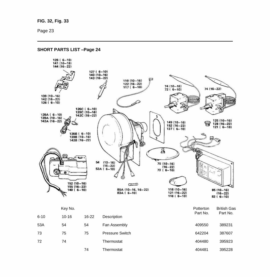
FIG. 32, Fig. 33
Page 23
SHORT PARTS LIST –Page 24
Key No.
Description
Potterton Part No.
British Gas Part No.
6-10 10-16 16-22
53A 54 54 Fan Assembly 409550 389231
73 75 75 Pressure Switch 642204 387607
72 74 Thermostat 404480 395923
74 Thermostat 404481 395228

83 85 85 Electronic Control 407676 336708
116 118 121 Thermostat Knob 200277 357634
140 152 155 Gas Control Valve 907219 392811
121 Main Burner Injector 410955 336831
125 Main Burner Injector 410497 358297
128 Main Burner Injector 410903 358298
126 139 142 Pilot Burner Assembly 402890 336728
126A 139A 142A Pilot Injector 402899 336855
126B 139B 142B Shear Off Union 402492 357932
126C 139C 142C Injector Securing Clip 402896 336856
128 141 144 Spark Earthing Bracket 205705 336730
127 Electrode 407679 336874
140 143 Electrode 407675 395924
117 119 122 Electrode Lead 205743 336724
137 149 152 Main Burner Gasket 200725 357995
83A 85A 85A Fuse 641903 336585
"All descriptions and illustrations contained in this leaflet have been carefully prepared but we reserve the right to make changes and improvements in our products whichmay affect the accuracy of the information contained in this leaflet"
Page 24
ADDENDUM 1 – Page 25
POTTERTON
NETAHEAT
ELECTRONIC
FLUES
FLUE LENGTH CRITERIA
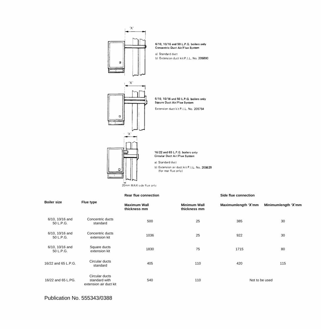
Boiler size Flue type
Rear flue connection Side flue connection
Maximum Wall thickness mm
Minimum Wall thickness mm
Maximumlength ‘X’mm Minimumlength ‘X’mm
6/10, 10/16 and 50 L.P.G.
Concentric ducts standard
500 25 385 30
6/10, 10/16 and 50 L.P.G.
Concentric ducts extension kit
1036 25 922 30
6/10, 10/16 and 50 L.P.G.
Square ducts extension kit
1830 75 1715 80
16/22 and 65 L.P.G. Circular ducts
standard 405 110 420 115
16/22 and 65 L.PG. Circular ducts standard with
extension air duct kit 540 110 Not to be used
Publication No. 555343/0388

Back page
Page 25