installation site survey – walchem web-based controllers · installation site survey – walchem...
TRANSCRIPT

Installation Site Survey – Walchem Web-Based Controllers April 27, 2004
General Installation Checklist Select a location for the controller(s) to be installed. The following criteria must be met: �� Vibration free surface �� Ambient temperature of area not to be out of the range of 0-49 C (32-120 F) �� Minimum of one square foot wall space for WebAlert, three square feet for
WebMaster �� 15 ampere, 100 – 240 VAC +/- 10% clean power source nearby �� The unit must be on its own circuit. A line filter protecting the equipment is
preferred �� Maximum cable length for devices connecting to WebAlert or WebMaster analog
(4-20 mA) inputs: 4000 feet. �� Maximum cable length for devices connecting to WebAlert or WebMaster digital
inputs: 1000 feet. �� Maximum cable lengths for sensors connecting to the WebMaster:
�� 250 feet (75 m) for conductivity �� 1000 feet (300 m)for pH/ORP
�� Avoid locations in close proximity to sources of electrical noise (motor starters, power transformers, variable speed motor drives, fan or blower motors, radio transmitters, etc.)
�� Avoid corrosive fumes or excessive moisture Cooling Tower Sample Plumbing Installation Checklist Most controllers are installed using in-line sensors with a flow switch. Installation is simplified when Walchem supplies pre-assembled flow manifolds. Refer to the installation drawing below. �� Verify that a tap is available on the discharge side of the recirculation pump for
the sample inlet to the WebMaster sensors �� Verify that a tap is available for the sample return on the suction side of the
recirculation pump �� The location of these taps must be such that the pressure will quickly equalize and
flow will stop once the recirculation pump stops �� Optional pH and ORP electrodes must be installed such that the measuring
surfaces will always remain wet. The U trap incorporated in our flow manifold assures this

HEA
TEX
CH
AN
GER
CO
OLI
NG
TO
WER
EHM
eter
ing
Pum
p(u
p to
6)
Posi
flow
Leve
l sw
itch
Mak
eup
cond
Mak
eup
wat
erFl
owm
eter
Ble
edFl
owm
eter
Blee
dVa
lve
pHEl
ectr
ode
OR
PEl
ectr
odeFl
owsw
itch
Con
duct
ivity
elec
trod
e
Inhi
bito
r,B
io1,
Bio
2,pH
Adj
ust,
OR
P A
djus
t,or
Dis
pers
ant
Inje
ctio
nVa
lve
Foot
valv
e
Y-st
rain
er
Y-st
rain
er
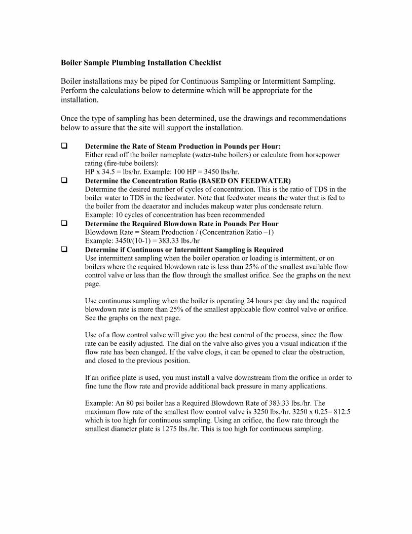
Boiler Sample Plumbing Installation Checklist Boiler installations may be piped for Continuous Sampling or Intermittent Sampling. Perform the calculations below to determine which will be appropriate for the installation. Once the type of sampling has been determined, use the drawings and recommendations below to assure that the site will support the installation. �� Determine the Rate of Steam Production in Pounds per Hour:
Either read off the boiler nameplate (water-tube boilers) or calculate from horsepower rating (fire-tube boilers): HP x 34.5 = lbs/hr. Example: 100 HP = 3450 lbs/hr.
�� Determine the Concentration Ratio (BASED ON FEEDWATER) Determine the desired number of cycles of concentration. This is the ratio of TDS in the boiler water to TDS in the feedwater. Note that feedwater means the water that is fed to the boiler from the deaerator and includes makeup water plus condensate return. Example: 10 cycles of concentration has been recommended
�� Determine the Required Blowdown Rate in Pounds Per Hour Blowdown Rate = Steam Production / (Concentration Ratio –1) Example: 3450/(10-1) = 383.33 lbs./hr
�� Determine if Continuous or Intermittent Sampling is Required Use intermittent sampling when the boiler operation or loading is intermittent, or on boilers where the required blowdown rate is less than 25% of the smallest available flow control valve or less than the flow through the smallest orifice. See the graphs on the next page. Use continuous sampling when the boiler is operating 24 hours per day and the required blowdown rate is more than 25% of the smallest applicable flow control valve or orifice. See the graphs on the next page. Use of a flow control valve will give you the best control of the process, since the flow rate can be easily adjusted. The dial on the valve also gives you a visual indication if the flow rate has been changed. If the valve clogs, it can be opened to clear the obstruction, and closed to the previous position. If an orifice plate is used, you must install a valve downstream from the orifice in order to fine tune the flow rate and provide additional back pressure in many applications. Example: An 80 psi boiler has a Required Blowdown Rate of 383.33 lbs./hr. The maximum flow rate of the smallest flow control valve is 3250 lbs./hr. 3250 x 0.25= 812.5 which is too high for continuous sampling. Using an orifice, the flow rate through the smallest diameter plate is 1275 lbs./hr. This is too high for continuous sampling.

�� Determine the Orifice or Flow Control Valve Size for this Blowdown Rate Use the following graphs to select a flow control device:
��
FLOW RATE IN LBS/HR FOR VARIOUS ORIFICES
02000400060008000
1000012000140001600018000
10 20 30 40 50 60 70 80 90 100 200 300
PRESSURE (psi)
LBS/
HR 1/8 inch dia
3/16 inch dia1/4 inch dia5/16 inch dia
FLOW CONTROL VALVE MAX. FLOW RATES IN LBS/HR
0
2000
4000
6000
8000
10000
12000
14000
16000
18000
20000
22000
24000
20 30 40 50 60 70 80 90 100 150 200 300 PRESSURE(PSI)
LBS/HR
1/2" 150 PSI
1/2" 300 PSI
3/4" 150 PSI
3/4" 300 PSI

�� Make sure the minimum water level in the boiler is at least 4-6 inches above the
skimmer blowdown line. If the skimmer line is closer to the surface, it is likely that steam will be drawn into the line instead of boiler water. The skimmer line must also be installed above the highest tube.
�� Maintain a 3/4 inch minimum pipe ID with no flow restrictions from the tap for the boiler skimmer blowdown line to the electrode. If the ID is reduced below 3/4 inch, then flashing will occur beyond that point and the conductivity reading will be low and erratic. Minimize the usage of tees, valves, elbows or unions between the boiler and the electrode.
�� A manual shut off valve should be installed so that the electrode can be removed and cleaned. This valve must be a full port valve in order to avoid a flow restriction. Keep the distance between the tap for the boiler skimmer line to the electrode as short as possible, to a maximum of 10 feet.
�� Mount the electrode in the side branch of a tee in a horizontal run of pipe. This will minimize entrapment of steam around the electrode and will allow any solids to pass through.
�� In order to obtain stable readings it is critical to align the hole in the conductivity electrode such that the direction of water flow is through the hole.
�� There MUST be a flow restriction after the electrode and/or control valve in order to provide back pressure. This flow restriction will be either a flow control valve or an orifice union. The amount of the flow restriction will effect the blowdown rate as well, and should be sized accordingly.
�� Install the motorized ball valve or solenoid valve per the manufacturer’s instructions.
��
REFER TO THE TYPICAL INSTALLTION DRAWINGS BELOW:

TYPICAL INSTALLATION: CONTINUOUS SAMPLING
EHM
eter
ing
Pum
p
Posi
flow
Leve
l sw
itch
Trea
tmen
tC
hem
ical
Foot
valv
e
TOR
EC
OM
ME
ND
ED
FEE
D L
OC
ATIO
N
To D
rain
Ski
mm
er B
low
dow
n Li
ne3/
4" M
in. u
p to
Ele
ctro
de
Full
Por
t Blo
ckVa
lve
Man
ual B
low
dow
n(N
orm
ally
Clo
sed)
Mot
oriz
ed
Bal
l or
Sol
enoi
dVa
lve
Flow
C
ontro
l Va
lve
or O
rific
eU
nion
CO
ND
UC
TIV
ITY
ELE
CTR
OD
E
¾" T
EE
Flow
C
ontro
l Va
lve
orO
rific
e U
nion To
Dra
in
To D
rain

TYPICAL INSTALLATION: INTERMITTENT SAMPLING
To D
rain
Ski
mm
er B
low
dow
n Li
ne3/
4" M
in. u
p to
Ele
ctro
de
Full
Por
t Blo
ckVa
lve
Man
ual B
low
dow
n(N
orm
ally
Clo
sed)
Mot
oriz
ed
Bal
l or
Sol
enoi
dVa
lve
Flow
C
ontro
l Va
lve
orO
rific
e U
nion
CO
ND
UC
TIV
ITY
ELE
CTR
OD
E
¾" T
EE
2 ft.
m
inim
um
1 to
3 ft
.m
axim
um
10 ft
. max
.w
ith m
inim
al v
alve
s, e
lbow
s &
uni
ons
TOD
RA
IN
EHM
eter
ing
Pum
p
Posi
flow
Leve
l sw
itch
Trea
tmen
tC
hem
ical
Foot
valv
e
STE
AM D
RU
M
TOR
EC
OM
ME
ND
ED
FEE
D L
OC
ATIO
N
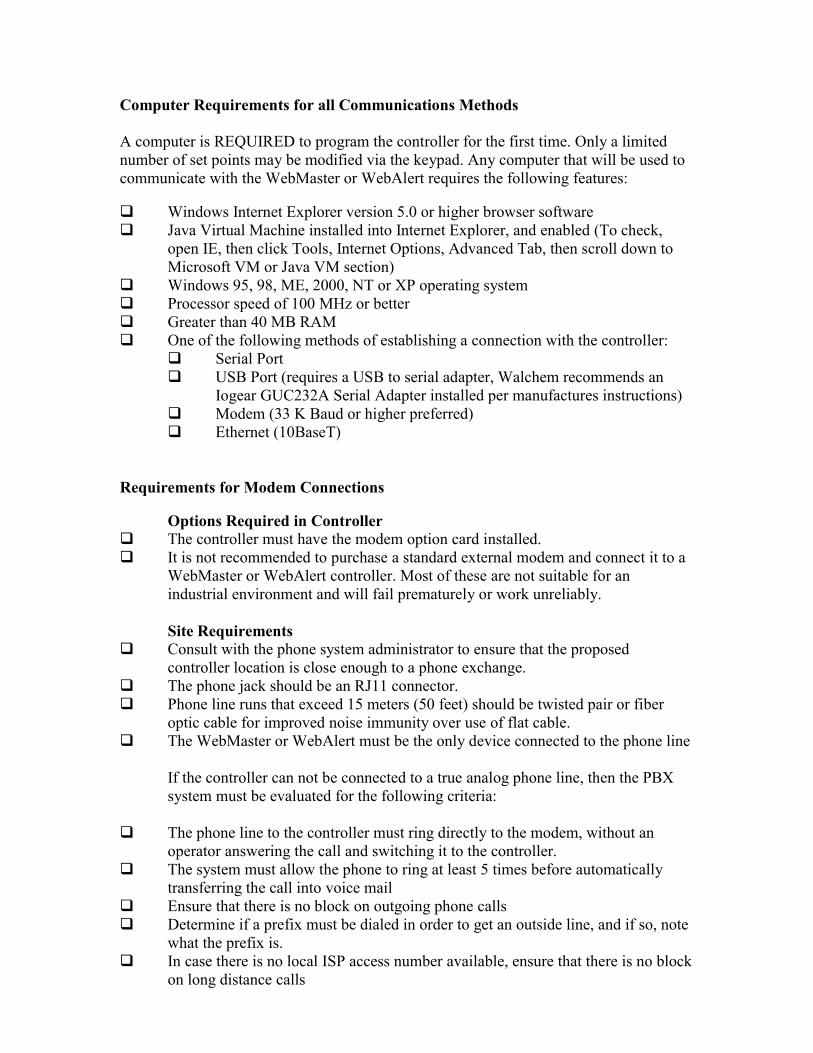
Computer Requirements for all Communications Methods A computer is REQUIRED to program the controller for the first time. Only a limited number of set points may be modified via the keypad. Any computer that will be used to communicate with the WebMaster or WebAlert requires the following features: �� Windows Internet Explorer version 5.0 or higher browser software �� Java Virtual Machine installed into Internet Explorer, and enabled (To check,
open IE, then click Tools, Internet Options, Advanced Tab, then scroll down to Microsoft VM or Java VM section)
�� Windows 95, 98, ME, 2000, NT or XP operating system �� Processor speed of 100 MHz or better �� Greater than 40 MB RAM �� One of the following methods of establishing a connection with the controller:
�� Serial Port �� USB Port (requires a USB to serial adapter, Walchem recommends an
Iogear GUC232A Serial Adapter installed per manufactures instructions) �� Modem (33 K Baud or higher preferred) �� Ethernet (10BaseT)
Requirements for Modem Connections
Options Required in Controller �� The controller must have the modem option card installed. �� It is not recommended to purchase a standard external modem and connect it to a
WebMaster or WebAlert controller. Most of these are not suitable for an industrial environment and will fail prematurely or work unreliably. Site Requirements
�� Consult with the phone system administrator to ensure that the proposed controller location is close enough to a phone exchange.
�� The phone jack should be an RJ11 connector. �� Phone line runs that exceed 15 meters (50 feet) should be twisted pair or fiber
optic cable for improved noise immunity over use of flat cable. �� The WebMaster or WebAlert must be the only device connected to the phone line
If the controller can not be connected to a true analog phone line, then the PBX system must be evaluated for the following criteria:
�� The phone line to the controller must ring directly to the modem, without an operator answering the call and switching it to the controller.
�� The system must allow the phone to ring at least 5 times before automatically transferring the call into voice mail
�� Ensure that there is no block on outgoing phone calls �� Determine if a prefix must be dialed in order to get an outside line, and if so, note
what the prefix is. �� In case there is no local ISP access number available, ensure that there is no block
on long distance calls

Requirements for Ethernet Connections
Options Required in Controller �� The WebMaster must have the Ethernet option card installed. This is a standard
feature of all WebAlert controllers Site Requirements
�� The location for mounting the controller must be within 100 meters (330 feet) of an Ethernet hub.
�� The network administrator must assign the controller a permanent IP address, subnet mask, and gateway. The controller does not support DHCP. Obtain this information from the administrator
�� Ensure that the information is correct, and that the network is compatible by doing the following tests. Use the help of the network administrator if necessary. These tests use a portable computer to simulate the WebMaster or WebAlert.
�� Connect a portable computer to the network at the same hub that will be
used by the controller. �� Go to the LAN Connection configuration of the potable computer and
change it to the addresses assigned to the WebMaster. For Windows 2000 and XP this is found in Control Panel/Network and Dialup Connections/Local Area Connection. Click Properties, then Internet Protocol (TCP/IP), then Properties. Select Use the following IP address and program it using the WebMaster’s assigned IP address, subnet mask and gateway.
�� Using the computers on the network that will be required to connect to the controller, verify that you can ping the WebMaster’s assigned IP address

Requirements for a Network of Controllers In a network of controllers, users are able to connect to the Master controller, and through the Master connect to the other controllers on the network. The Master may be accessed via any method (RS-232, Ethernet, Direct Modem, or ShoulderTap) and the Slaves accessed through the Master via Ethernet. It is not necessary for the controllers to be connected to the user’s LAN. A small private network of controllers connected together via hubs will also suffice if the distance between controllers and a hub is less than 330 feet. Refer to the diagrams below for examples: Network that utilizes the customer’s LAN:
Network that is independent of the LAN:
Master Slaves
Slave
Master Slaves
WebAlert Slave XMTRS
Hub

Requirements for a Network of Controllers (continued) Options Required in Controller
�� All WebMasters in the network must have the Ethernet option card installed. This is a standard feature of all WebAlert controllers.
�� If the Master controller is to be accessed via a phone line (Direct modem or ShoulderTap), then it must have a modem option installed.
�� In order to be capable of being a Master, the Master Networking option must be purchased. Site Requirements
�� If the Master will be connected to a phone line, adhere to the requirements above for Modem Connections.
�� Each controller must be within 100 meters (330 feet) of an Ethernet hub. �� Each controller must be given an IP address, subnet mask and gateway. If the
controllers will be connected independent of a LAN, then no further action is required.
�� If the controllers will be connected to the LAN, the network administrator must assign each one a fixed IP address, subnet mask and gateway. DHCP is not supported. Obtain this information from the network administrator.
�� Ensure that the information is correct, and that the network is compatible, by doing the following tests. Use the help of the network administrator if necessary. These tests use a portable computer to simulate the WebMaster or WebAlert. �� Connect a portable computer to the network at the same hub that will be
used by the controller. �� Go to the LAN Connection configuration of the potable computer and
change it to the addresses assigned to the WebMaster. For Windows 2000 and XP this is found in Control Panel/Network and Dialup Connections/Local Area Connection. Click Properties, then Internet Protocol (TCP/IP), then Properties. Select Use the following IP address and program it using the WebMaster’s assigned IP address, subnet mask and gateway.
�� Using the computers on the network that will be required to connect to the controller, verify that you can ping the WebMaster’s assigned IP address
�� One additional test is required to verify that the controllers on the LAN are able to communicate with each other. This test is important to ensure that the controllers will not be installed on separate subnetworks. �� Place a computer at each controller location, programmed with the IP
address, subnet mask and gateway that will be used by the controllers. �� Verify that the computer in the Master location is able to ping all of the
other IP addresses.