installation, technical and maintenance manual · when vacon® 100 x drive is connected to the...
TRANSCRIPT

vacon®100 xac drives
Installation, Technical and Maintenance Manual

vacon • 0
INDEXDocument code (Original Instructions): DPD00534H
Order code: DOC-INS03985+DLUK
Rev. H
Revision release date: 10.7.15
1. Safety................................................................................................................41.1 Signs....................................................................................................................................41.2 Units ....................................................................................................................................41.3 Danger.................................................................................................................................51.4 Warnings .............................................................................................................................61.5 Earthing and earth fault protection ....................................................................................71.6 Insulation system..............................................................................................................101.7 Compatibility with RCDs ...................................................................................................111.8 Extended temperature range ...........................................................................................111.9 Electro-magnetic compatibility (EMC)..............................................................................111.10 Declaration of conformity .................................................................................................122. Receipt of delivery ..........................................................................................162.1 Type designation code.......................................................................................................172.2 order codes .......................................................................................................................182.3 Unpacking and lifting the AC drive ...................................................................................192.4 Accessories .......................................................................................................................192.4.1 Frame MM4 .......................................................................................................................192.4.2 Frame MM5 .......................................................................................................................202.4.3 Frame MM6 .......................................................................................................................202.4.4 STO terminal connector....................................................................................................212.4.5 ‘Product modified’ sticker.................................................................................................212.4.6 Disposal.............................................................................................................................213. Mounting.........................................................................................................223.1 Dimensions mm4 ..............................................................................................................223.2 Dimensions mm5 ..............................................................................................................233.3 Dimensions mm6 ..............................................................................................................243.4 Introduction of modules....................................................................................................253.5 Mounting ...........................................................................................................................263.5.1 Wall-mounting ..................................................................................................................273.5.2 Motor-mounting................................................................................................................273.5.3 Segregated modules.........................................................................................................273.6 Cooling ..............................................................................................................................284. Power cabling .................................................................................................304.1 Circuit breaker ..................................................................................................................324.2 UL standards on cabling ...................................................................................................324.3 Description of the terminals .............................................................................................334.4 Cable dimensioning and selection....................................................................................364.4.1 Cable and fuse sizes, frames MM4 to MM6......................................................................364.4.2 Cable and fuse sizes, frames MM4 to MM6, North America............................................384.4.3 Brake resistor cables........................................................................................................394.4.4 Control cables ...................................................................................................................394.5 Cable installation ..............................................................................................................405. Control unit.....................................................................................................465.1 Control unit cabling...........................................................................................................475.1.1 Control cable sizing ..........................................................................................................475.1.2 Standard I/O terminals .....................................................................................................485.1.3 Relay and thermistor input terminals ..............................................................................495.1.4 Safe Torque off (STO) terminals .......................................................................................49
Service support: find your nearest Vacon service center at www.vacon.com

vacon • 1
5.1.5 Selection of terminal functions with dip switches ...........................................................505.1.6 Isolating digital inputs from ground .................................................................................505.1.7 Bus termination of the RS485 connection ........................................................................515.2 I/O cabling and Fieldbus connection ................................................................................525.2.1 Prepare for use through Ethernet ....................................................................................525.2.2 Prepare for use through RS485........................................................................................535.2.3 RS485 cable data...............................................................................................................545.3 Battery installation for Real Time Clock (RTC) ................................................................556. Commissioning ...............................................................................................586.1 Commissioning of the drive ..............................................................................................596.2 Changing EMC protection class........................................................................................606.3 Running the motor ............................................................................................................626.3.1 Cable and motor insulation checks ..................................................................................626.4 Maintenance......................................................................................................................637. Technical data.................................................................................................647.1 AC drive power ratings......................................................................................................647.1.1 Mains voltage 3AC 208-240V.............................................................................................647.1.2 Mains voltage 3AC 380-480/500V......................................................................................657.1.3 Definitions of overloadability ............................................................................................667.2 Brake resistor ratings.......................................................................................................677.3 VACON® 100 X - technical data........................................................................................687.3.1 Technical information on control connections.................................................................718. Options............................................................................................................748.1 Mains switch......................................................................................................................748.1.1 Installation ........................................................................................................................748.2 Control Keypad..................................................................................................................788.2.1 Mounting onto the drive ....................................................................................................788.2.2 Installation ........................................................................................................................798.2.3 Wall-mounting ..................................................................................................................818.2.4 Graphical and Text keypad................................................................................................838.2.5 VACON® keypad with graphical display...........................................................................848.2.6 VACON® keypad with text segment display.....................................................................918.2.7 Fault Tracing .....................................................................................................................958.3 Heater (arctic option) ......................................................................................................1048.3.1 Safety...............................................................................................................................1048.3.2 Dangers ...........................................................................................................................1048.3.3 Technical data .................................................................................................................1048.3.4 Fuses ...............................................................................................................................1058.3.5 Mounting instructions: MM4 Example............................................................................1058.4 Option boards ..................................................................................................................1098.5 Flange adapter ................................................................................................................1108.5.1 Mounting instructions: MM4 Example............................................................................1139. Safe Torque Off .............................................................................................1169.1 General description.........................................................................................................1169.2 Warnings .........................................................................................................................1169.3 Standards ........................................................................................................................1179.4 The principle of STO........................................................................................................1189.4.1 Technical details .............................................................................................................1199.5 Connections.....................................................................................................................1209.5.1 Safety Capability Cat. 4 / PL e / SIL 3 .............................................................................1219.5.2 Safety Capability Cat. 3 / PL e / SIL 3 .............................................................................1239.5.3 Safety Capability Cat. 2 / PL d / SIL 2 .............................................................................1239.5.4 Safety Capability Cat. 1 / PL c / SIL 1..............................................................................1249.6 Commissioning ...............................................................................................................125

vacon • 2
9.6.1 General wiring instructions ............................................................................................1259.6.2 Checklist for commissioning ..........................................................................................1259.7 Parameters and fault tracing .........................................................................................1269.8 Maintenance and diagnostics .........................................................................................126
Service support: find your nearest Vacon service center at www.vacon.com

vacon • 3

Safety vacon • 4
1. SAFETY
This manual contains clearly marked warning information which is intended for your personal safe-ty and to avoid any unintentional damage to the product or connected appliances.
Please read the warning information carefully.
VACON® 100 X is a drive designed to control asynchronous AC motors and permanent magnetmotors. The product is intended to be installed in a restricted access location and for a generalpurpose use.
Only VACON® authorized, trained and qualified personnel are allowed to install, operate and maintain the drive.
1.1 SignsThe cautions and warnings are marked as follows:
Table 1. Warning signs.
1.2 UnitsThe dimensions used in this manual conform to International Metric System units, otherwise known as SI (Système International d’Unités) units. For the purpose of the equipment's UL certification, some of these dimensions are accompanied by their imperial equivalents.
= DANGEROUS VOLTAGE!
= HOT SURFACE
= WARNING or CAUTION
Physical dimension SI value US value Conversion factor US designation
length 1 mm 0.0394 inch 25.4 inch
Weight 1 kg 2.205 lb 0.4536 pound
Speed 1 min-1 1 rpm 1 revolution per minute
Temperature 1 °C (T1) 33.8 °F (T2) T2 = T1 x 9/5 + 32 Fahrenheit
Torque 1 Nm 8.851 lbf in 0.113 pound-force inches
Power 1 kW 1.341 HP 0.7457 horsepower
Table 2. Unit conversion table.
Service support: find your nearest Vacon service center at www.vacon.com 1

1
vacon • 5 Safety
1.3 Danger
The components of the power unit of VACON® 100 X drives are live when the drive is con-nected to mains potential. Coming into contact with this voltage is extremely dangerous andmay cause death or severe injury.
The motor terminals (U, V, W), the brake resistor terminals and the DC-terminals are livewhen VACON® 100 X Drive is connected to the mains, even if the motor is not running.
After disconnecting the AC drive from the mains, wait until the indicators on the keypad go out(if no keypad is connected, see the indicators on the cover). Wait an additional 30 secondsbefore doing any work on the connections of VACON® 100 X Drive. Do not open the unit beforethis time has expired. After expiration of this time, use measuring equipment to absolutelyensure that no voltage is present. Always ensure absence of voltage before starting any elec-trical work!
The control I/O-terminals are isolated from the mains potential. However, the relay outputsand other I/O-terminals may have a dangerous control voltage present even when VACON®
100 X drive is disconnected from the mains.
Before connecting the AC drive to mains make sure that the powerhead of VACON® 100 XDrive is mounted firmly on the terminal box.
During a coast stop (see the Application Manual), the motor is still generating voltage to thedrive. Therefore, do not touch the components of the AC drive before the motor has completelystopped and wait until the indicators on the keypad go out (if no keypad is connected, see theindicators on the cover). Wait an additional 30 seconds before starting any work on the drive.

Safety vacon • 6
1.4 Warnings
VACON® 100 X AC drive is meant for fixed installations (on the motor or on the wall) only.
Only DVC A circuits (Decisive Voltage Class A, according to IEC 61800-5-1) are allowed tobe connected to the control unit. This advice aims to protect both the drive and the client-application. VACON® is not responsible for direct or consequential damages resultingfrom unsafe connections of external circuits to the drive. See paragraph 1.6 for moredetails.
Do not perform any measurements when the AC drive is connected to the mains.
The touch current of VACON® 100 X AC drives exceeds 3.5mA AC. According to standardEN61800-5-1, a reinforced protective ground connection must be ensured. See para-graph 1.5 for more details.
If the AC drive is used as a part of a machine, the machine manufacturer is responsiblefor providing the machine with a supply disconnecting device (EN 60204-1). See para-graph 4.1 for more details.
Only spare parts delivered by VACON® can be used.
At power-up or fault reset, the motor will start immediately if the start signal is active,unless the pulse control for Start/Stop logic has been selected) and the STO inputs are readyto be used (normal operation). The I/O functionalities (including start inputs) may changeif parameters, applications or software are changed. Disconnect, therefore, the motor ifan unexpected start can cause danger. This is valid only if STO inputs are energized. Forprevention on unexpected restart, use appropriate safety relay connected to the STOinputs.
The motor starts automatically after automatic fault reset if the autoreset function isactivated. See the Application Manual for more detailed information. This is valid only ifSTO inputs are energized. For prevention on unexpected restart, use appropriate safetyrelay connected to the STO inputs.
Before performing any measurement on the motor or on the motor cable, disconnectthe motor cable from the AC drive.
Do not perform any voltage withstand test on any part of VACON® 100 X. The tests shall beperformed according to a specific procedure. Ignoring this procedure may damage theproduct.
Do not touch the components on the circuit boards. Static voltage discharge may damagethe components.
Check that the EMC level of the AC drive corresponds to the requirements of your supplynetwork. See paragraph 6.2 for more details.
In a domestic environment, this product may cause radio interference in which case sup-plementary mitigation measures may be required.
Optional keypad is IP66/Type 4X outdoor rated. Strong exposure to direct sunlight or toheavy temperatures might cause the degradation of display LCD.
Service support: find your nearest Vacon service center at www.vacon.com 1

1
vacon • 7 Safety
1.5 Earthing and earth fault protection
The VACON® 100 X AC drive must always be earthed with an earthing conductor connected to the earthing terminal marked with .
See Table 16 and Table 17 for the required cross-section of phase conductor and protective earth-ing conductor (both made of copper).
Since the touch current exceeds 3.5 mA AC, according to EN61800-5-1, the MM4 and MM5 shallhave a fixed connection and provision of an additional terminal for a second protective earthingconductor of the same cross-sectional area as the original protective earthing conductor. MM6shall have a fixed installation and a cross-section of the protective earthing conductor of at least 10mm2 Cu.
On the terminal-box, three screws (for MM4 and MM5) and two screws (for MM6)are provided forORIGINAL and MOTOR protective earthing conductors: the customer can choose the screw for eachone.
The cross-sectional area of every protective earthing conductor which does not form a part of thesupply cable or cable enclosure shall, in any case, be not less than:
• 2.5 mm2 if mechanical protection is provided or• 4 mm2 if mechanical protection is not provided. For cord-connected equipment, provisions
shall be made so that the protective earthing conductor in the cord shall, in the case of fail-ure of the strain-relief mechanism, be the last conductor to be interrupted.
The power-head is earthed through metal aglets, located on the terminal-box, which fit into springbaskets on the powerhead. See Figure 1, Figure 2 and Figure 3 for the location of the screws (threefor MM4 and MM5, two for MM6) and the metal aglets (one for MM4 and MM5, two for MM6). Please,pay attention not to damage or remove these aglets.
CAUTION!

Safety vacon • 8
Figure 1. Earth connections and metal aglet in MM4.
Figure 2. Earth connections and metal aglet in MM5.
Earth connection
Metal aglet
Earth connection
Earth connection
Earth connections
Metal aglet
Earth connection
Service support: find your nearest Vacon service center at www.vacon.com 1

1
vacon • 9 Safety
Figure 3. Earth connections and metal aglet in MM6.
However, always follow the local regulations for the minimum size of the protective earthing conductor.
NOTE: Due to the high capacitive currents present in the AC drive, fault current protective switchesmay not function properly.
Earth connection Earth connection
Metal aglet Metal aglet

Safety vacon • 10
1.6 Insulation system
A distinction has to be made for the following three groups of terminals, according the insulation system of VACON® 100 X:
• Mains and motor connections (L1, L2, L3, U, V, W) • Relays (R01, R02)(*) • Thermistor-input • Control terminals (I/Os, RS485, Ethernet, STO)
The Control terminals (I/Os, RS485, Ethernet, STO) are isolated from the Mains (the insulation is re-inforced, according to IEC 61800-5-1) and the GND terminals are referred to PE.
This is important when you need to connect other circuits to the drive and test the complete assem-bly. Should you have any doubt or question, please contact your local VACON® distributor.
Figure 4. Insulation system.
Please, consider carefully the insulation system depicted in Figure 4 before connect-ing any circuit to the unit.
(*) The relays may be used also with DVC A circuits. This is possible only if both relays are used with DVC A circuit: to mix Mains and DVC A is not allowed.
POWER UNITL1L2L3
UVW
R01 __
R02 __
DC- DC+/R+ R-
10Vref __
Analog Inputs __
Digital Inputs__
Digital Outputs__
24V __
Ethernet __
RS485 __
STO __
___Thermistor
Keypad
CONTROL UNIT
Reinforced
Mains
Mains
DVC A
DVC A orMains(*)
Service support: find your nearest Vacon service center at www.vacon.com 1

1
vacon • 11 Safety
1.7 Compatibility with RCDs
1.8 Extended temperature rangeVACON® 100 X has an integrated cooling system, independent from the motor fan. Under maxi-mum operating conditions, the ambient temperature cannot exceed 40 °C. See Table 28 andTable 29 for the output rated current. Higher temperatures are allowed only with derating of theoutput current. With derating the unit can operate up to 60°C. See the Figure 5.
Figure 5. Temperature-output current derating curve.
NOTE: the maximum allowed switching frequency above 50°C is 1.5 kHz.
The AC drive is cooled down by air-ventilation. Therefore, make sure that enough free space is leftaround the AC drive to ensure sufficient air circulation (see for more details the mounting instruc-tions on chapter 3).
1.9 Electro-magnetic compatibility (EMC)The VACON® 100 X complies with IEC 61000-3-12, provided that the short circuit power (SSC) isgreater than or equal to 120 at the interface point between the user's supply and the public system.It is the responsibility of the installer or user of the equipment to ensure, by consultation with thedistribution network operator if necessary, that the equipment is connected only to a supply with ashort-circuit power SSC greater than or equal to 120.
This product can cause a d.c. current in the protective earthing conductor. Where a re-sidual current-operated protective (RCD) or monitoring (RCM) device is used for pro-tection in case of direct or indirect contact, only an RCD or RCM of Type B is allowed on the supply side of this product.
Ambient temperature (°C)
Per
cent
rate
d ou
tput
cur
rent
(% I N
)
10 20 30 40 50
100
75
50
25
0-10
150
60
Temperature - Output Current Derating Curve
Safety vacon • 12
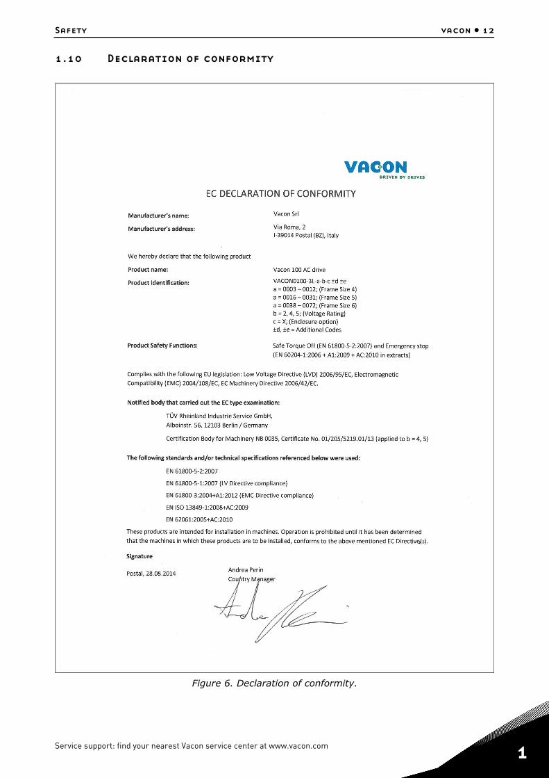
1.10 Declaration of conformity
Figure 6. Declaration of conformity.
Service support: find your nearest Vacon service center at www.vacon.com 1

1
vacon • 13 Safety
Figure 7. STO certificate.

Safety vacon • 14
NOTE! You can download the English and French product manuals with applicable safety, warn-ing and caution information from www.vacon.com/downloads.
REMARQUE Vous pouvez télécharger les versions anglaise et française des manuels produit contenant l’ensemble des informations de sécurité, avertissements et mises en garde applica-bles sur le site www.vacon.com/downloads.
Service support: find your nearest Vacon service center at www.vacon.com 1

1
vacon • 15 Safety

Receipt of delivery vacon • 16
2. RECEIPT OF DELIVERY
Check the correctness of delivery by comparing your order data to the drive information found onthe package label. If the delivery does not correspond to your order, contact the supplier immedi-ately. See chapter 2.4.
Figure 8. VACON® package label.
Marks:3234500378Cust. Ord. No:
Application:FW0065V008Firmware:
EMC level C2
380-480 VIP66 / Type 4X
31 ARated current:
122245B.ID:V0789012245S/N:
22345678901234567890123456729012345
20-AB3L00315A02B5H1MB1C-12345678Code:
VACON0100-3L-0031-4-XType:
0022345628AC DRIVE
223456789012245
Vacon type code
Ratedcurrent
SupplyvoltageApplicationcode
IP classEMC level
Serial number
CUSTOMER NAMECustomer’sorder number
Vacon ordernumber
Batch ID
Service support: find your nearest Vacon service center at www.vacon.com 2

2
vacon • 17 Receipt of delivery
2.1 Type designation codeVACON® type designation code is formed of a nine-segment code and optional +codes. Each seg-ment of the type designation code uniquely corresponds to the product and options you have or-dered. The code is of the following format:
VACON0100-3L-0061-4-X +xxxx +yyyy
VACON
This segment is common for all products.
0100
Product range:
0100 = VACON® 100
3L
Input/Function:
3L = Three-phase input
0061
Drive rating in ampere; e.g. 0061 = 61 A
See Table 28, Table 29 and Table 30 for all
the drive ratings.
4
Supply voltage:
2 = 208-240 V4 = 380-480 V5 = 380-500 V
X
-IP66/ Type 4X
-EMC-level C2
-Two relay outputs
-One thermistor input
-STO function
-GP software package installed
+xxxx +yyyy
Additional codes (Several options possible).
Examples of additional codes:
+HMGR
Graphical keypad IP66
+F0065
HVAC software package installed
+F0159
FLOW software package installed
+SRBT
Integrated battery for real time clock
+FBIE
Onboard fieldbus protocols activated (Ethernet IP and Profinet IO)
+FBEI
Onboard Ethernet IP protocol activated
+FBPN
Onboard Profinet IO protocol activated

Receipt of delivery vacon • 18
2.2 order codesThe order codes for Vacon 100 X drive family are shown in the following table:
Frame size Order code Description
Supply voltage 3AC 208-240V
MM4
VACON0100-3L-0007-2-X 1.1 kW - 1.5 HP drive
VACON0100-3L-0008-2-X 1.5 kW - 2.0 HP drive
VACON0100-3L-0011-2-X 2.2 kW - 3.0 HP drive
VACON0100-3L-0012-2-X 3.0 kW - 4.0 HP drive
MM5 VACON0100-3L-0018-2-X 4.0 kW - 5.0 HP drive
VACON0100-3L-0024-2-X 5.5 kW - 7.5 HP drive
VACON0100-3L-0031-2-X 7.5 kW - 10.0 HP drive
MM6 VACON0100-1L-0048-2-X 11.0 kW - 15.0 HP drive
VACON0100-1L-0062-2-X 15.0 kW - 20.0 HP drive
Supply voltage 3AC 380-480V
MM4
VACON0100-3L-0003-4-X 1.1 kW - 1.5 HP drive
VACON0100-3L-0004-4-X 1.5 kW - 2.0 HP drive
VACON0100-3L-0005-4-X 2.2 kW - 3.0 HP drive
VACON0100-3L-0008-4-X 3.0 kW - 4.0 HP drive
VACON0100-3L-0009-4-X 4.0 kW - 5.0 HP drive
VACON0100-3L-0012-4-X 5.5 kW - 7.5 HP drive
MM5
VACON0100-3L-0016-4-X 7.5 kW - 10.0 HP drive
VACON0100-3L-0023-4-X 11.0 kW - 15.0 HP drive
VACON0100-3L-0031-4-X 15.0 kW - 20.0 HP drive
MM6
VACON0100-3L-0038-4-X 18.5 kW - 25.0 HP drive
VACON0100-3L-0046-4-X 22.0 kW - 30.0 HP drive
VACON0100-3L-0061-4-X 30.0 kW - 40.0 HP drive
VACON0100-3L-0072-4-X 37.0 kW - 50.0 HP drive
Supply voltage 3AC 380-500V
MM4
VACON0100-3L-0003-5-X 1.1 kW - 1.5 HP drive
VACON0100-3L-0004-5-X 1.5 kW - 2.0 HP drive
VACON0100-3L-0005-5-X 2.2 kW - 3.0 HP drive
VACON0100-3L-0008-5-X 3.0 kW - 4.0 HP drive
VACON0100-3L-0009-5-X 4.0 kW - 5.0 HP drive
VACON0100-3L-0012-5-X 5.5 kW - 7.5 HP drive
MM5
VACON0100-3L-0016-5-X 7.5 kW - 10.0 HP drive
VACON0100-3L-0023-5-X 11.0 kW - 15.0 HP drive
VACON0100-3L-0031-5-X 15.0 kW - 20.0 HP drive
MM6
VACON0100-3L-0038-5-X 18.5 kW - 25.0 HP drive
VACON0100-3L-0046-5-X 22.0 kW - 30.0 HP drive
VACON0100-3L-0061-5-X 30.0 kW - 40.0 HP drive
VACON0100-3L-0072-5-X 37.0 kW - 50.0 HP drive
Table 3. Order codes of Vacon 100 X. See chapter 7 for more details.
Service support: find your nearest Vacon service center at www.vacon.com 2

2
vacon • 19 Receipt of delivery
2.3 Unpacking and lifting the AC driveThe weights of the AC drives vary according to frame size. You may need to use a piece of speciallifting equipment to move the converter from its package. Note the weights of each individual framesize in Table 4 below.
Table 4. Frame weights.
VACON® 100 X drives have undergone scrupulous tests and quality checks at the factory before theyare delivered to the customer. However, after unpacking the product, check that no signs of trans-port damage are to be found on the product and that the delivery is complete.
Should the drive have been damaged during shipping, please contact the cargo insurance companyor the carrier in the first instance.
2.4 AccessoriesAfter having opened the transport package and lifted the drive out, check immediately that these various accessories were included in the delivery. The contents of the accessories bag differ by drive size:
2.4.1 Frame MM4
FrameWeight
[kg] [lb]
MM4 8.8 19.4
MM5 14.9 32.8
MM6 31.5 69.4
Item Quantity Purpose
STO terminal connector 1 Six pin black connector (see Figure 9) to use STO function
M4 x 12 DIN6900-3-Combi-Delta-Tx screw 10 Screws for control cable clamps
M1-3 Cable clamp 5 Clamping control cables
M4 x 12 DIN6900-3-Combi-Delta-Tx screw 6 Screws for power cable clamps
M25 Cable clamp 3 Clamping power cables
‘Product modified’ sticker 1 Information about modifications
HMI cap*
*. Provided only if the drive is delivered with the keypad.
1 Closing cap for the HMI connector
Table 5. Content of accessory bag, MM4.
Receipt of delivery vacon • 20
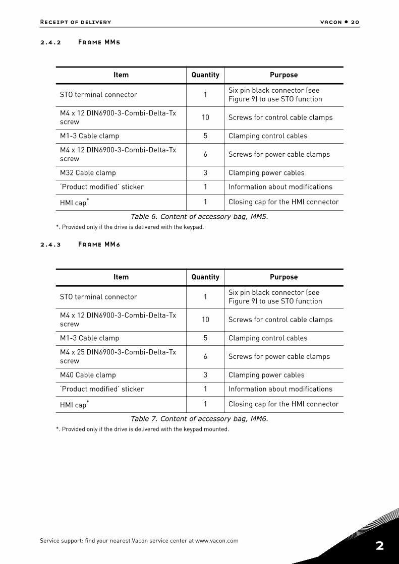
2.4.2 Frame MM5
2.4.3 Frame MM6
Item Quantity Purpose
STO terminal connector 1 Six pin black connector (see Figure 9) to use STO function
M4 x 12 DIN6900-3-Combi-Delta-Tx screw 10 Screws for control cable clamps
M1-3 Cable clamp 5 Clamping control cables
M4 x 12 DIN6900-3-Combi-Delta-Tx screw 6 Screws for power cable clamps
M32 Cable clamp 3 Clamping power cables
‘Product modified’ sticker 1 Information about modifications
HMI cap*
*. Provided only if the drive is delivered with the keypad.
1 Closing cap for the HMI connector
Table 6. Content of accessory bag, MM5.
Item Quantity Purpose
STO terminal connector 1 Six pin black connector (see Figure 9) to use STO function
M4 x 12 DIN6900-3-Combi-Delta-Tx screw 10 Screws for control cable clamps
M1-3 Cable clamp 5 Clamping control cables
M4 x 25 DIN6900-3-Combi-Delta-Tx screw 6 Screws for power cable clamps
M40 Cable clamp 3 Clamping power cables
‘Product modified’ sticker 1 Information about modifications
HMI cap*
*. Provided only if the drive is delivered with the keypad mounted.
1 Closing cap for the HMI connector
Table 7. Content of accessory bag, MM6.
Service support: find your nearest Vacon service center at www.vacon.com 2

2
vacon • 21 Receipt of delivery
2.4.4 STO terminal connector
Figure 9. STO connector.
2.4.5 ‘Product modified’ stickerIn the small plastic bag included in the delivery you will find a silver Product modified sticker. Thepurpose of the sticker is to notify the service personnel about the modifications made in the ACdrive. Attach the sticker on the side of the AC drive to avoid losing it. Should the AC drive be latermodified mark the change on the sticker.
Figure 10. ‘Product modified’ sticker.
2.4.6 Disposal
When the device reaches the end of its operating life do not disposeof it as a part of standard household garbage. Main components ofthe product can be recycled, but some need to be fragmented toseparate different types of materials and components that need tobe treated as special waste from electrical and electroniccomponents. To ensure environmentally sound and safe recyclingtreatment, the product can be taken to appropriate recycling centeror returned to the manufacturer.Observe local and other applicable laws as they may mandatespecial treatment for specific components or special treatment maybe ecologically sensible.
Product modified
Date:Date:Date:
1306
4.em
f

Mounting vacon • 22
3. MOUNTING
VACON® 100 X is the ideal solution for a decentralised installation. It is conceived to be mounted on a wall or directly on the motor, saving space and reducing the cabling complexity. In both of the cas-es, it must be ensured that the mounting plane is even.
3.1 Dimensions mm4
Figure 11. VACON® 100 X drive dimensions, MM4.
FrameDimensions W x H x D
[mm] [in]
MM4 190.7 x 315.3 x 196.4 7.51 x 12.41 x 7.73
MM4 +HMGR 190.7 x 315.3 x 213.8 7.51 x 12.41 x 8.42
315,3
190,7
187,8
213,8
293,0
296,5
5,9
143,5
196,4
Service support: find your nearest Vacon service center at www.vacon.com 3

3
vacon • 23 Mounting
3.2 Dimensions mm5
Figure 12. VACON® 100 X drive dimensions, MM5.
FrameDimensions W x H x D
[mm] [in]
MM5 232.6 x 367.4 x 213.5 9.16 x 14.46 x 8.41
MM5 +HMGR 232.6 x 367.4 x 230.8 9.16 x 14.46 x 9.08
367,4
203,7
230,8
180,0
345,2
349,2
6,1
232,6
213,5

Mounting vacon • 24
3.3 Dimensions mm6
Figure 13. VACON® 100 X drive dimensions, MM6.
FrameDimensions W x H x D
[mm] [in]
MM6 349.5 x 499.8 x 235.4 13.76 x 19.68 x 9.27
MM6 +HMGR 349.5 x 499.8 x 254.2 13.76 x 19.68 x 10.00
229,6
254,2
322,0
349,5
382,8
385,3
499,8
8,2
235,4
Service support: find your nearest Vacon service center at www.vacon.com 3

3
vacon • 25 Mounting
3.4 Introduction of modulesThe mechanical concept of VACON® 100 X drive is based on two segregated parts, power and con-trol, connected to each other by pluggable terminals. The power unit, called powerhead, includesall the power electronics such as the EMC-filter, IGBTs, capacitors, choke or power boards whilethe control board and the control terminals are located in the terminal box.
Figure 14. VACON® 100 X drive modules.
Powerhead
Terminal box

Mounting vacon • 26
3.5 MountingThe drive consists of two main elements:
1. The terminal box that includes the power terminals and control board with the control terminals and
2. The powerhead containing all the power electronics.
To install the drive, both parts need to be separated. The terminal box must be fixed first and allcabling done. After this, the powerhead will be plugged on the terminal box and fixed with 4 (MM4and MM6) or 6 (MM5) dedicated screws located on top side of the powerhead (see Figure 15.). In or-der to guarantee specified IP protection, recommended fastening torque is 2-3 Nm. The screwsshould be tightened crosswise.
Figure 15. Separation of modules(MM5 example).
Service support: find your nearest Vacon service center at www.vacon.com 3

3
vacon • 27 Mounting
3.5.1 Wall-mountingThe drive can be mounted in vertical or horizontal position on the wall or any other relatively evenmounting plane or machine frame and fixed with the screws recommended in Table 8.
Recommended screw or bolt size for MM4 is M5, for MM5 M6 and MM6 is M8.
3.5.2 Motor-mountingThe drive can also be mounted on a motor (on top or on any side of the motor). The drive is equipped with a cooling system independent of the motor. Motor-mounting requires special adapting com-ponents. Contact your local VACON® distributor for additional information.
3.5.3 Segregated modulesIn order to ease replacements in case of failure, the power and the control sub-systems are en-closed in two segregated parts, connected together through pluggable terminals:
• Power-head: heat-sink enclosing all power electronics• Terminal-box: block containing unit control and power terminals
Firstly, the terminal-box has to be fixed and the cabling has to be done. Secondly, the power-head has to be plugged and fixed to the terminal-box with dedicated screws (see Table 9). In order to pre-serve the specified IP protection class, the recommended fastening torque is 2-3 Nm.
Frame Screw number Screw size
MM4 4 M5
MM5 4 M6
MM6 4 M8
Table 8. Screws for wall mounting.
Frame Screw number Screw size
MM4 4 M5
MM5 6 M5
MM6 4 M6
Table 9. Screws for fixing the powerhead to the terminal box.

Mounting vacon • 28
3.6 CoolingThe AC drive produces heat in operation and is cooled down by air circulated by a fan. The coolingconcept is independent of the motor fan.
Enough free space shall be left around the AC drive to ensure sufficient air circulation and cooling.Different acts of maintenance may also require a certain amount of free space.
The minimum clearances given in Table 10 must not be exceeded. It is also important to ensure thatthe temperature of the cooling air does not exceed the maximum ambient temperature of the con-verter.
Contact local VACON® distributor for more information on required clearances in different instal-lations.
Table 10. Min. clearances around AC drive.
A = Clearance left and right from the driveB = Clearance above the driveC = Clearance underneath the AC drive
Figure 16. Installation space.
Table 11. Required cooling air.
Should you need further details on the cooling system of the VACON® 100 X, please contact your local VACON® distributor.
Min clearance [mm]
Type A B C
All types 80 160 60
Type Cooling air required [m3/h]
MM4 140
MM5 140
MM6 280
B
C
AAA
Service support: find your nearest Vacon service center at www.vacon.com 3

3
vacon • 29 Mounting

Power cabling vacon • 30
4. POWER CABLING
The mains cables are connected to terminals L1, L2 and L3 and the motor cables to terminalsmarked with U, V and W. See principal connection diagram in Figure 17. See also Table 12 for thecable recommendations for different EMC levels.
Figure 17. Principal connection diagram.
Use cables with heat resistance in accordance with the application requirements. The cables andthe fuses must be dimensioned according to the AC drive nominal OUTPUT current which you canfind on the rating plate.
U/T1
V/T2
W/T3M
L1
L2
L3
DC+
R-
DC-
Keypad
Control unit
Power unit
Service support: find your nearest Vacon service center at www.vacon.com 4

4
vacon • 31 Power cabling
Table 12. Cable types required to meet standards.
1 = Power cable intended for fixed installation and the specific mains voltage. Shielded cable notrequired. (MCMK or similar recommended).
2 = Symmetrical power cable equipped with concentric protection wire and intended for the spe-cific mains voltage. (MCMK or similar recommended). See Figure 18.
3 = Symmetrical power cable equipped with compact low-impedance shield and intended forthe specific mains voltage. [MCCMK, EMCMK or similar recommended; Recommendedcable transfer impedance (1...30MHz) max. 100 mOhm/m]. See Figure 18.*360º earthing of the shield with cable glands in motor end needed for EMC level C2.
4 = Screened cable equipped with compact low-impedance shield (JAMAK, SAB/ÖZCuY-O orsimilar).
Figure 18.
NOTE: The EMC requirements are fulfilled at factory defaults of switching frequencies (all frames).NOTE: If safety switch is connected the EMC protection shall be continuous over the whole cable installation.
EMC levels
Cable type1st environment 2nd environment
Category C2 Category C3 Category C4
Mains cable 1 1 1
Motor cable 3* 2 2
Control cable 4 4 4
ShieldPE conductors
ShieldPE conductor
Power cabling vacon • 32
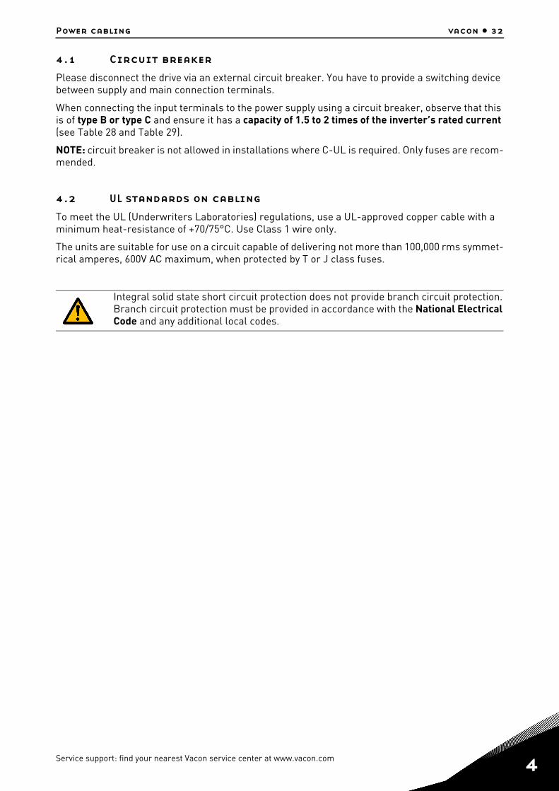
4.1 Circuit breakerPlease disconnect the drive via an external circuit breaker. You have to provide a switching device between supply and main connection terminals.
When connecting the input terminals to the power supply using a circuit breaker, observe that this is of type B or type C and ensure it has a capacity of 1.5 to 2 times of the inverter’s rated current (see Table 28 and Table 29).
NOTE: circuit breaker is not allowed in installations where C-UL is required. Only fuses are recom-mended.
4.2 UL standards on cablingTo meet the UL (Underwriters Laboratories) regulations, use a UL-approved copper cable with a minimum heat-resistance of +70/75°C. Use Class 1 wire only.
The units are suitable for use on a circuit capable of delivering not more than 100,000 rms symmet-rical amperes, 600V AC maximum, when protected by T or J class fuses.
Integral solid state short circuit protection does not provide branch circuit protection.Branch circuit protection must be provided in accordance with the National ElectricalCode and any additional local codes.
Service support: find your nearest Vacon service center at www.vacon.com 4

4
vacon • 33 Power cabling
4.3 Description of the terminalsThe following pictures describe the power terminals and the typical connections in Vacon® 100X drives.
Figure 19. Power connections, MM4.
Terminal Description
L1L2L3
These terminals are the input connections for the power supply.
DC-DC+/R+R-
DC bus terminals (DC- DC+)andBrake resistor terminals (R+ R-)
U/T1V/T2W/T3
These terminals are for motor connections.
Table 13. Terminal description.
PES
AC power supplyThree phases
PE
3ACMotor
PE
brakeresistor

Power cabling vacon • 34
Figure 20. Power connections, MM5.
Terminal Description
L1L2L3
These terminals are the input connections for the power supply.
DC-DC+/R+R-
DC bus terminals (DC- DC+)andBrake resistor terminals (R+ R-)
U/T1V/T2W/T3
These terminals are for motor connections.
Table 14. Terminal description.
PES
AC power supplyThree phases
PE
3ACMotor
PE
brakeresistor
Service support: find your nearest Vacon service center at www.vacon.com 4

4
vacon • 35 Power cabling
Figure 21. Power connections, MM6.
Terminal Description
L1L2L3
These terminals are the input connections for the power supply.
DC-DC+/R+R-
DC bus terminals (DC- DC+)andBrake resistor terminals (R+ R-)
U/T1V/T2W/T3
These terminals are for motor connections.
Table 15. Terminal description.
PES
AC power supplyThree phases
PE
3ACMotor
PE
brakeresistor

Power cabling vacon • 36
4.4 Cable dimensioning and selectionTable 16 and Table 17 show the minimum dimensions of the Cu-cables and the corresponding fusesizes.
These instructions apply only to cases with one motor and one cable connection from the AC driveto the motor. In any other case, ask the factory for more information.
4.4.1 Cable and fuse sizes, frames MM4 to MM6The recommended fuse type is gG/gL (IEC 60269-1). The fuse voltage rating should be selected ac-cording to the supply network. The final selection should be made according to local regulations,cable installation conditions and cable specification. Bigger fuses than those recommended belowshall not be used.
Check that the fuse operating time is less than 0.4 seconds. Operating time depends on used fusetype and impedance of the supply circuit. Consult the factory about faster fuses. VACON® also rec-ommends high speed gS (IEC 60269-4) fuse ranges.
Table 16. Cable and fuse sizes for VACON® 100 X.
Frame Type IINPUT[A]
Fuse(gG/gL)
[A]
Mains and motor cable
Cu [mm2]
Terminal cable size
Main terminal[mm2]
Earth terminal[mm2]
MM4
0003 4 - 0004 4 0003 5 - 0004 5 3.4 - 4.6 6 3*1.5+1.5 0.5—10 solid
0.5—6 strandedM4 ring terminal or 1—6
0007 2 - 0008 2 0005 4 - 0008 4 0005 5 - 0008 5
6.0 - 7.25.4 - 8.1 10 3*1.5+1.5 0.5—10 solid
0.5—6 strandedM4 ring terminal or 1—6
0011 2 - 0012 20009 4 - 0012 40009 5 - 0012 5
9.7 - 10.99.3 - 11.3 16 3*2.5+2.5 0.5—10 solid
0.5—6 strandedM4 ring terminal or 1—6
MM5
0018 20016 4 0016 5
16.115.4 20 3*6+6 0.5—16 solid
or strandedM5 ring terminal or 1—10
0024 20023 40023 5
21.721.3 25 3*6+6 0.5—16 solid
or strandedM5 ring terminal or 1—10
0031 20031 40031 5
27.728.4 32 3*10+10 0.5—16 solid or
strandedM5 ring terminal or 1—10
MM6
0038 40038 5 36.7 40 3*10+10 M6 ring terminal M6 ring terminal
0048 20046 40046 5
43.843.6 50 3*16+16 M6 ring terminal M6 ring terminal
0062 20061 40061 5
57.058,2 63 3*25+16 M6 ring terminal M6 ring terminal
0072 40072 5 67.5 80 3*35+16 M6 ring terminal M6 ring terminal
Service support: find your nearest Vacon service center at www.vacon.com 4

4
vacon • 37 Power cabling
The terminal sizes are intended for 1 conductor. For MM6, the max. diameter of the ring terminal is 14 mm. The cable dimensioning is based on the criteria of the International Standard IEC60364-5-52: Cables must be PVC-isolated; Max number of parallel cables is 9.
When using cables in parallel, NOTE HOWEVER that the requirements of both the cross-sectional area and the max number of cables must be observed.For important information on the requirements of the earthing conductor, see chapter Earthing and earth fault protection of the standard.For the correction factors for each temperature, see International Standard IEC60364-5-52.

Power cabling vacon • 38
4.4.2 Cable and fuse sizes, frames MM4 to MM6, North AmericaThe recommended fuse type is class T (UL & CSA). The fuse voltage rating should be selected ac-cording to the supply network. The final selection should be made according to local regulations, cable installation conditions and cable specification. Bigger fuses than those recommended below shall not be used.
Check that the fuse operating time is less than 0.4 seconds. Operating time depends on used fuse type and impedance of the supply circuit. Consult the factory about faster fuses. VACON® also rec-ommends high speed J (UL & CSA) fuse ranges.
Table 17. Cable and fuse sizes for VACON® 100 X.
The cable dimensioning is based on the criteria of the Underwriters’ Laboratories UL508C:Cables must be PVC-isolated; Max ambient temperature +40 °C (104 °F), max temperature of cable surface +70/+75 °C (158/167 °F); Use only cables with concentric copper shield; Max number of parallel cables is 9.
When using cables in parallel, NOTE HOWEVER that the requirements of both the cross-sectional area and the max number of cables must be observed.
Frame Type IINPUT[A]
Fuse(class T)
[A]
Mains and motor cable
Cu
Terminal cable size
Main terminal Earth terminal
MM4
0003 4 - 0004 4 0003 5 - 0004 5 3.4 - 4.6 6 AWG14 AWG24-AWG10 AWG17-AWG10
M4 ring terminal
0007 2 - 0008 2 0005 4 - 0008 4 0005 5 - 0008 5
6.0 - 7.25.4 - 8.1 10 AWG14 AWG24-AWG10 AWG17-AWG10
M4 ring terminal
0011 20009 40009 5
9.79.3 15 AWG14 AWG24-AWG10 AWG17-AWG10
M4 ring terminal
0012 20012 40012 5
10.911.3 20 AWG14 AWG24-AWG10 AWG17-AWG10
M4 ring terminal
MM5
0018 20016 4 0016 5
16.115.4 25 AWG10 AWG20-AWG5 AWG17-AWG8
M5 ring terminal
0024 20023 40023 5
21.721.3 30 AWG10 AWG20-AWG5 AWG17-AWG8
M5 ring terminal
0031 20031 4 0031 5
27.728.4 40 AWG8 AWG20-AWG5 AWG17-AWG8
M5 ring terminal
MM6
0038 40038 5 36.7 50 AWG4
AWG13-AWG0M6 ring terminal
AWG13-AWG2M6 ring terminal
0048 20046 40046 5
43.843.6 60 AWG4 AWG13-AWG0
M6 ring terminalAWG13-AWG2M6 ring terminal
0062 20061 40061 5
57.058,2 80 AWG4 AWG13-AWG0
M6 ring terminalAWG13-AWG2M6 ring terminal
0072 40072 5 67.5 100 AWG2 AWG9-AWG2/0
M6 ring terminalAWG9-AWG2/0M6 ring terminal
Service support: find your nearest Vacon service center at www.vacon.com 4

4
vacon • 39 Power cabling
For important information on the requirements of the earthing conductor, see standard Underwriters’ Labo-ratories UL508C.
For the correction factors for each temperature, see the instructions of standard Underwriters’ Laboratories UL508C.
4.4.3 Brake resistor cablesVACON® 100 X AC drives are equipped with terminals for an optional external brake resistor. These terminals are marked with DC+/R+ and R-. See Table 31 and Table 32 for the resistor ratings.
4.4.4 Control cablesFor information on control cables see chapter Control unit.

Power cabling vacon • 40
4.5 Cable installation• Before starting, check that none of the components of the AC drive is live. Read carefully the
warnings in chapter 1.• Place the motor cables sufficiently far from other cables• Avoid placing the motor cables in long parallel lines with other cables.• If the motor cables run in parallel with other cables note the minimum distances between
the motor cables and other cables given in table below.
• The given distances also apply between the motor cables and signal cables of other systems.• The maximum lengths of motor cables (shielded) are 100 m (MM4) and 150 m (MM5 and
MM6).• The motor cables should cross other cables at an angle of 90 degrees. • If cable insulation checks are needed, see chapter Cable and motor insulation checks.
Start the cable installation according to the instructions below:
Figure 22. Stripping of cables.
Distance between cables, [m]
Shielded cable, [m]
0.3 ≤ 50
1.0 ≤ 200
1 Strip the motor and mains cables as recommended below.
D1B1
C1A1
D2
C2
Earth conductor
MAINS MOTOR
Shield
E
Earth conductor
Service support: find your nearest Vacon service center at www.vacon.com 4

4
vacon • 41 Power cabling
Table 18. Cables stripping lengths [mm].IEC installation:
Figure 23. Cable entry plate, MM4.
Figure 24.Cable entry plate, MM5.
Frame A1 B1 C1 D1 C2 D2 E
MM4 15 70 10 30 7 30
as short as possibleMM5 20 70 10 40 10 40
MM6 20 90 15 60 15 60
2• Remove the cable entry plate. The cable entry system is a combination of a
cable entry plate (see the figure below) and cable glands. In the cable entry plate there are several openings available for the cables with ISO metric thread.
• Open only the inlet holes where you need to run the cables.
3 • Choose the correct cable glands according to drive and cable size as shown in the following pictures.

Power cabling vacon • 42
Figure 25.Cable entry plate, MM6.
Figure 26.Cable gland.
4• Cable glands must be made of plastic materials. They are used for sealing
cables passing through cable entries to ensure the characteristics of the enclosure.
Plastic cable glands are recommend. If metal cable glands are needed, all insula-tion system requirements and all protective earthing requirements have to be ful-filled in accordance with the national electrical regulations and IEC 61800-5-1.
5 • Screw the cable glands on the cable entry holes using the proper tightening torque as shown in Table 19.
Service support: find your nearest Vacon service center at www.vacon.com 4

4
vacon • 43 Power cabling
Tightening torques of cable glands:
UL installation:
Figure 27.Cable entry plate, MM4 UL installation.
Frame Gland screw type [metric]
Tightening torque [Nm]/[lb-in.]
[Nm] lb-in.
MM4M16 1.0 8.9
M25 4.0 35.5
MM5
M16 1.0 8.9
M25 4.0 35.5
M32 7.0 62.1
MM6
M16 1.0 8.9
M25 4.0 35.5
M40 10.0 88.7
Table 19. Tightening torque and dimension of cable glands.
6• To connect NPT pipes to Vacon®100X, use the optional metal cable entry plate
(included in -R02 option) to meet UL installation rules. • One metal conduit plate with accessories (screws and gasket) is delivered in a
separate bag together with the drive. See the following figures for moredetails.

Power cabling vacon • 44
Figure 28.Cable entry plate, MM5 UL installation.
Figure 29.Cable entry plate, MM6 UL installation.
Service support: find your nearest Vacon service center at www.vacon.com 4

4
vacon • 45 Power cabling
Cable installation:
Tightening torques of cable terminals:
Table 20. Tightening torques of terminals.
7 • All the (3) terminal box openings are closed with the standard plastic plateswith the metric threads.
8• The metal cable entry plate for UL installation has to be installed in place of
one of standard plastic cable entries provided with the default package. Themetal cable entry plate has three not-threaded openings: input line, motor andI/Os and can be mounted only on left or right-hand side of the drive.
9• Flexible or rigid cable conduit can be used. • Use proper fittings to join and terminate rigid conduit tubing, and protect it
from damage too.• The proper selection of electrical conduit materials, fittings, and installation
are important for safe electrical wiring.
10 • Setscrew fittings are commonly used with conduit; they provide weather tightjoints that are firm to keep the IP degree of the drive.
11• Pass the cables (supply cable, motor cable, brake cable and I/O cables) through
the conduits (UL connections) or through the cable glands (IEC connections)and cable entries.
12 • Detach the cable clamps and the grounding clamps.
13
Connect the stripped cables:• Expose the shield of both cables in order to make a 360-degree connection with
the cable clamp (reverse the shield over the plastic cover of the cable and fix all together).
• Connect the phase conductors of the supply and motor cables into their respective terminals.
• Form the rest of the cable shield of both cables into “pigtails” and make a grounding connection with the clamp. Make the pigtails just long enough to reach and be fixed to the terminal - no longer.
Frame Type
Tightening torque [Nm]/[lb-in.]
Power and motor terminals
Tightening torque [Nm]/[lb-in.]
EMC grounding clamps
Tightening torque, [Nm]/[lb-in.]
Grounding terminals
[Nm] lb-in. [Nm] lb-in. [Nm] lb-in.
MM40007 2 - 0012 20003 4 - 0012 4 0003 5 - 0012 5
1.2—1.5 10.6—13.3 1.5 13.3 2.0 17.7
MM50018 2 - 0031 20016 4 - 0031 4 0016 5 - 0031 5
1.2—1.5 10.6—13.3 1.5 13.3 2.0 17.7
MM60048 2 - 0062 20038 4 - 0072 4 0038 5 - 0072 5
4—5 35.4—44.3 1.5 13.3 2.0 17.7
14 • Check the connection of the earth cable to the motor and the AC drive termi-
nals marked with .

Control unit vacon • 46
5. CONTROL UNIT
Remove the powerhead of the drive to reveal the terminal box with the control terminals.
The control unit of the AC drive consists of the control board and additional boards (option boards)connected to the slot connectors of the control board. The locations of boards, terminals andswitches are presented in Figure 30 below.
Figure 30. Locations of components in control unit.
When delivered from the factory, the control unit of the AC drive contains the standard controllinginterface - the control and relay terminals of the control unit - unless otherwise specifically or-dered. On the next pages you will find the arrangement of the control I/O and the relay terminals,the general wiring diagram and the control signal descriptions.
Number Meaning
1 Control terminals 1-11 (see chapter 5.1.2)
2 Control terminals 12-30, A-B (see chapter 5.1.2)
3 Relay terminals (see chapter 5.1.2)
4 Thermistor input (see chapter 5.1.2)
5 STO terminals
6 Dip switches
7 Ethernet terminal (see chapter chapter 5.2.1)
8 Option boards
Table 21. Locations of components in control unit.
8 8
4
7
5
31 2
6
Service support: find your nearest Vacon service center at www.vacon.com 5

5
vacon • 47 Control unit
The control board can be powered externally (+24VDC, max. 1000mA, ±10%) by connecting the ex-ternal power source to terminal #30, see chapter 5.1.2. This voltage is sufficient for parameter set-ting and for keeping the control unit active. Note however that the measurements of the main circuit(e.g. DC-link voltage, unit temperature) are not available when the mains is not connected.
5.1 Control unit cablingThe principal terminal block placement is presented in Figure 31 below. The control board is equipped with 22 fixed control I/O terminals and the relay board with 6+2. Additionally, the termi-nals for the Safe Torque Off (STO) function (see chapter chapter 9.) can be seen in the picture below. All signal descriptions are also given in Table 23.
Figure 31. Control terminals.
5.1.1 Control cable sizingThe control cables shall be at least 0.5 mm2 screened multicore cables, see Table 22. The maxi-mum terminal wire size is 2.5 mm2 for the relay terminals and 1.5 mm2 for other terminals.
Find the tightening torques of the control and relay board terminals in Table 22.
Terminal screwTightening torque
Nm lb-in.
I/O terminals and STO terminals (screw M2) 0.5 4.5
Relay terminals (screw M3) 0.5 4.5
Table 22. Control cable tightening torques.

Control unit vacon • 48
5.1.2 Standard I/O terminalsThe terminals of the Standard I/Os and the Relays are described below. For more information on the connections, see chapter 7.
The terminals shown on shadowed background are assigned for signals with optional functions se-lectable with DIP switches. See more information in chapter 5.1.5 and in chapter 5.1.6.
Table 23. Control I/O terminal signals and connection example.
Standard I/O
Terminal Signal
1 +10 Vref Reference output
2 AI1+Analogue input, voltage or current
3 AI1-Analogue input com-mon
4 AI2+Analogue input, voltage or current
5 AI2-Analogue input com-mon
6 24Vout 24V aux. voltage
7 GND I/O ground
8 DI1 Digital input 1
9 DI2 Digital input 2
10 DI3 Digital input 3
11 CM Common for DI1-DI6*
*. Can be isolated from ground, see chap-ter chapter 5.1.6.
12 24Vout 24V aux. voltage
13 GND I/O ground
14 DI4 Digital input 4
15 DI5 Digital input 5
16 DI6 Digital input 6
17 CM Common for DI1-DI6*
18 AO1+Analogue output,voltage or current
19 AO-/GNDAnalogue output com-mon
30 +24 Vin24V auxiliary input voltage
A RS485 Serial bus, negative
B RS485 Serial bus, positive
Reference potentiometer 1...10 kΩ
Remote reference4...20mA/0...10V
mA
Service support: find your nearest Vacon service center at www.vacon.com 5

5
vacon • 49 Control unit
5.1.3 Relay and thermistor input terminals
5.1.4 Safe Torque off (STO) terminalsFor more information on the functionalities of the Safe Torque Off (STO), see chapter 9.
Table 24. I/O terminal signals for relay and thermistor terminals and connection example.
Relays and thermistor
Terminal Signal
21 RO1/1 Relay output 1
22 RO1/2
23 RO1/3
24 RO2/1 Relay output 2
25 RO2/2
26 RO2/3
28 TI1+Thermistor input
29 TI1-
Table 25. I/O terminal signals for the STO functions.
Safe Torque Off terminals
Terminal Signal
S1 Isolated digital input 1 (inter-changeable polarity);+24V ±20% 10...15mAG1
S2 Isolated digital input 2 (inter-changeable polarity);+24V ±20% 10...15mAG2
F+Isolated feedback (CAUTION! Polarity to be respected);+24V ±20%
F-Isolated feedback (CAUTION! Polarity to be respected);GND
From standard I/O
From term. #13
From term. #6
RUN

Control unit vacon • 50
5.1.5 Selection of terminal functions with dip switchesThe VACON® 100 X drive embodies five so-called dip switches that allow for three functional selec-tions each. The shadowed terminals in Table 23 can be functionally modified with the dip switches. The switches have three positions: C, 0 and V. The switch in the position “C” means that the input or the output has been set in current mode. The switch in the position “V” means voltage mode.The middle position ”0” is for Test mode. See Figure 32 to locate the switches and make appropriate selections for your requirements. Factory defaults are: AI1 = V; AI2 = C, AO = C.
Figure 32. Dip switches for analogue inputs and analogue output.
5.1.6 Isolating digital inputs from groundThe digital inputs (terminals 8-10 and 14-16) on the standard I/O board can be isolated from ground by setting the dip switch to position ‘0’. The switch in the position “1” means that the common of digital input has been connected to 24 V (negative logic). The switch in the position “2” means that the common of digital inputs has been connected to ground (positive logic). See Figure 33. Locate the switch and set it in desired position. Factory default is 2.
Figure 33. Digital inputs dip switch.
Service support: find your nearest Vacon service center at www.vacon.com 5

5
vacon • 51 Control unit
5.1.7 Bus termination of the RS485 connectionThis dip switch is related to the RS485 connection. It’s used for bus termination. The bus termina-tion must be set to the first and to the last device on the network. This switch in position “0” means that a termination resistor of 120 ohm is connected and the termination of the bus has been set. This switch in the position “1” means that a pull-up and a pull-down resistors of 10 kOhm have been connected for biasing purpose. The switch in the position “2” means no termination and no biasing resistors have been connected. Factory default is 2. See Figure 34.
Figure 34. RS485 dip switch.

Control unit vacon • 52
5.2 I/O cabling and Fieldbus connectionThe AC drive can be connected to fieldbus either through RS485 or Ethernet. The connection for RS485 is on the standard I/O terminals (A and B) and the connection for Ethernet is left to the con-trol terminals. See Figure 35.
Figure 35.
5.2.1 Prepare for use through Ethernet
For more detailed information, see the user’s manual of the fieldbus you are using.
5.2.1.1 Ethernet cable data
Table 26. Ethernet cable data.
1 Connect the Ethernet cable (see specification on page 52) to its terminal and run the cable through the conduit plate.
2 Remount the powerhead. NOTE: When planning the cable runs, remember to keep the distance between the Ethernet cable and the motor cable at a minimum of 30 cm.
Connector Shielded RJ45 connector. Note: max length of the connector 40 mm.
Cable type CAT5e STPCable length Max. 100m
1 2 3 4 5 6 7 8 9 10 11
12 13 14 15 16 17 18 19 30 BA
RS485terminals
Ethernetconnection
Service support: find your nearest Vacon service center at www.vacon.com 5
5
vacon • 53 Control unit
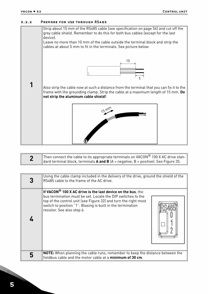
5.2.2 Prepare for use through RS485
1
Strip about 15 mm of the RS485 cable (see specification on page 54) and cut off the grey cable shield. Remember to do this for both bus cables (except for the last device).Leave no more than 10 mm of the cable outside the terminal block and strip the cables at about 5 mm to fit in the terminals. See picture below.
Also strip the cable now at such a distance from the terminal that you can fix it to the frame with the grounding clamp. Strip the cable at a maximum length of 15 mm. Do not strip the aluminum cable shield!
2 Then connect the cable to its appropriate terminals on VACON® 100 X AC drive stan-dard terminal block, terminals A and B (A = negative, B = positive). See Figure 35.
3Using the cable clamp included in the delivery of the drive, ground the shield of the RS485 cable to the frame of the AC drive.
4
If VACON® 100 X AC drive is the last device on the bus, the bus termination must be set. Locate the DIP switches to the top of the control unit (see Figure 32) and turn the right most switch to position “1”. Biasing is built in the termination resistor. See also step 6.
5 NOTE: When planning the cable runs, remember to keep the distance between the fieldbus cable and the motor cable at a minimum of 30 cm.
10
5

Control unit vacon • 54
5.2.3 RS485 cable data
Table 27. RS485 cable data.
6
The bus termination must be set for the first and the last device of the fieldbus line. See picture below and step 4. We recommend that the first device on the bus and, thus, terminated, was the Master device.
Connector 2.5 mm2
Cable type STP (Shielded Twisted Pair), type Belden 9841 or similar
Cable length Depends on the used fieldbus. See respective bus manual.
Fieldbus
= Bus termination Resistor = 220 ohm
Terminationactivated
Terminationactivated with
DIP switchTerminationdeactivated
Vacon 100X Vacon 100X Vacon 100X Vacon 100X Vacon 100X
Service support: find your nearest Vacon service center at www.vacon.com 5

5
vacon • 55 Control unit
5.3 Battery installation for Real Time Clock (RTC)Enabling the functions of the Real Time Clock (RTC) requires that an optional battery is installedin the VACON® 100 X drive.
Detailed information on the functions of the Real Time Clock (RTC) can be found in the ApplicationManual. See the following figures to install the battery on the control box of Vacon® 100X frequencyconverter.
Figure 36. Remove the three screws on the control box.
1 Remove the three screws on the control box as shown in Figure 36.
2 Rotate and open the cover of the control box as shown in Figure 37.

Control unit vacon • 56
Figure 37. Open the cover of control box.
3 Install the battery in the correct place and connect it to the control box. See Figure 38 for battery location and connector.
Service support: find your nearest Vacon service center at www.vacon.com 5

5
vacon • 57 Control unit
Figure 38. Location and connector for the battery on the control box.
Location for battery
Connector forbattery

Commissioning vacon • 58
6. COMMISSIONING
Before commissioning, note the following directions and warnings:
Internal components and circuit boards of VACON® 100 X drive (except for the galvan-ically isolated I/O terminals) are live when it is connected to the mains potential.Coming into contact with this voltage is extremely dangerous and may cause deathor severe injury.
The motor terminals U, V, W and the brake resistor terminals R-/R+ are live whenVACON® 100 X drive is connected to the mains, even if the motor is not running.
The control I/O-terminals are isolated from the mains potential. However, the relayoutputs and other I/O-terminals may have a dangerous control voltage presenteven when VACON® 100 X drive is disconnected from the mains.
Do not make any connections to or from the frequency converter when it is connectedto the mains.
After disconnecting the AC drive from the mains, wait until the fan stops and theindicators on the powerhead go out. Wait an additional 30 seconds before doing anywork on the connections of VACON®100 X Drive. Do not open the unit before this timehas expired. After expiration of this time, use a measuring equipment to absolutelyensure that no voltage is present. Always ensure absence of voltage before startingany electrical work!
Before connecting the AC drive to mains make sure that the powerhead VACON® 100X Drive is mounted firmly on the terminal box.
Service support: find your nearest Vacon service center at www.vacon.com 6
6
vacon • 59 Commissioning
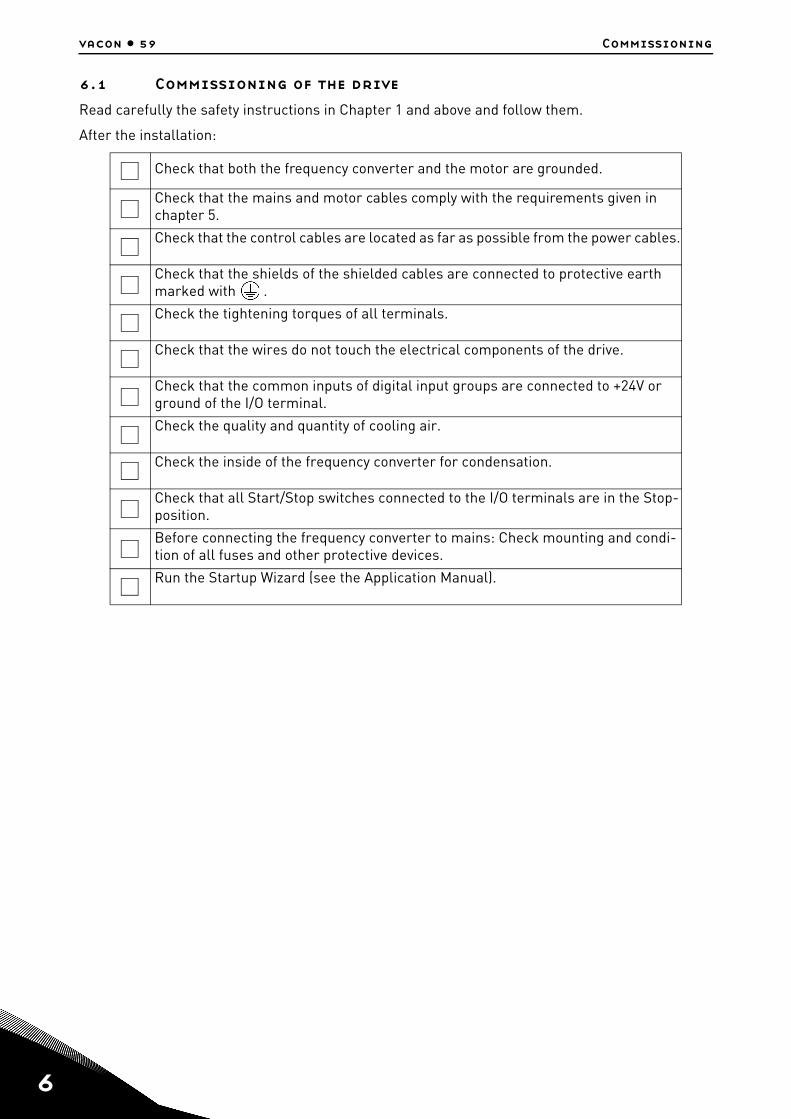
6.1 Commissioning of the driveRead carefully the safety instructions in Chapter 1 and above and follow them.
After the installation:
Check that both the frequency converter and the motor are grounded.
Check that the mains and motor cables comply with the requirements given in chapter 5.
Check that the control cables are located as far as possible from the power cables.
Check that the shields of the shielded cables are connected to protective earth marked with .
Check the tightening torques of all terminals.
Check that the wires do not touch the electrical components of the drive.
Check that the common inputs of digital input groups are connected to +24V or ground of the I/O terminal.
Check the quality and quantity of cooling air.
Check the inside of the frequency converter for condensation.
Check that all Start/Stop switches connected to the I/O terminals are in the Stop-position.
Before connecting the frequency converter to mains: Check mounting and condi-tion of all fuses and other protective devices.
Run the Startup Wizard (see the Application Manual).

Commissioning vacon • 60
6.2 Changing EMC protection classIf your supply network is an IT (impedance-grounded) system but your AC drive is EMC-protectedaccording to class C1 or C2 you need to modify the EMC protection of the AC drive to EMC-level T(C4). This is done by removing the EMC screws as described below:
Figure 39. Locations of EMC screws in MM4.
Figure 40. Locations of EMC screws in MM5.
Warning! Do not perform any modifications on the AC drive when it is connected to mains.
1Separate the powerhead and the terminal box. Turn the powerhead upside down and remove the two screws marked in Figure 39 (for MM4), Figure 40 (for MM5) and in Figure 42(for MM6).
Service support: find your nearest Vacon service center at www.vacon.com 6
6
vacon • 61 Commissioning
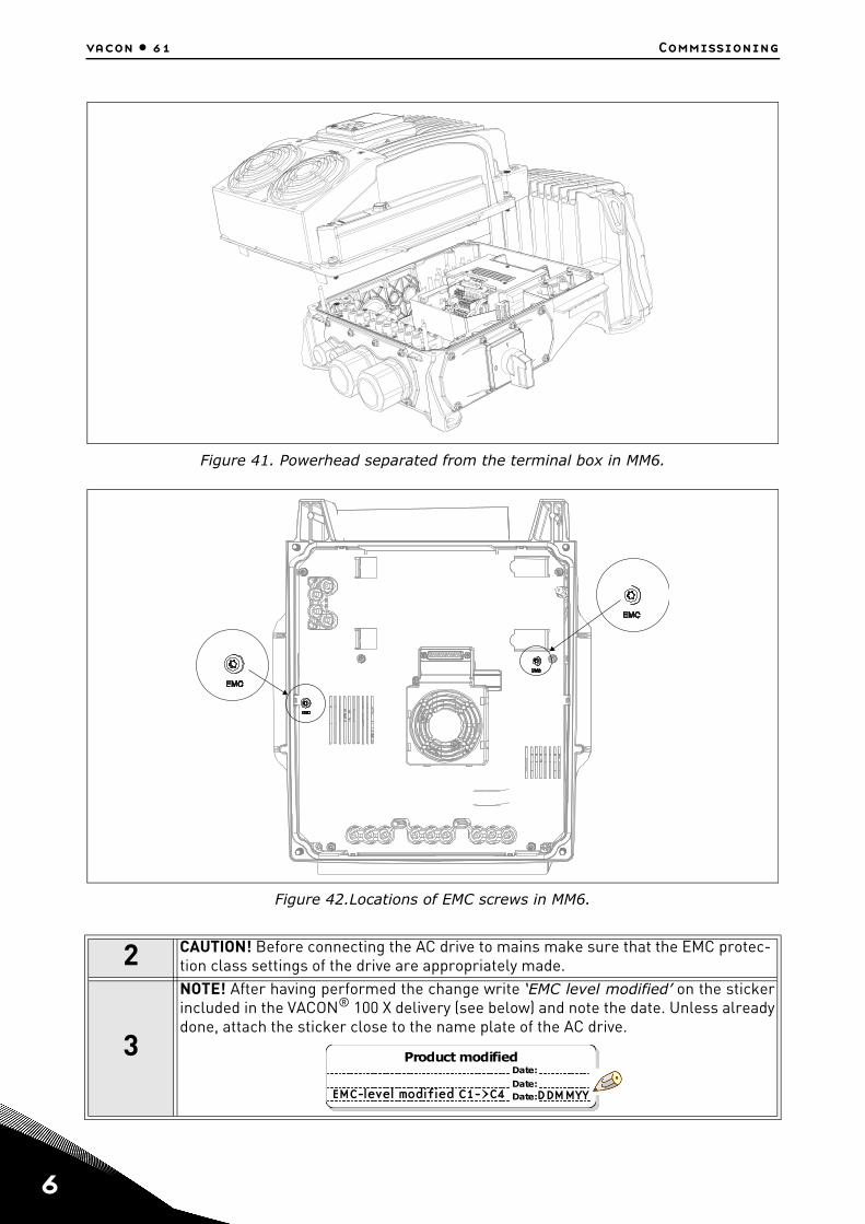
Figure 41. Powerhead separated from the terminal box in MM6.
Figure 42.Locations of EMC screws in MM6.
2 CAUTION! Before connecting the AC drive to mains make sure that the EMC protec-tion class settings of the drive are appropriately made.
3
NOTE! After having performed the change write ‘EMC level modified’ on the stickerincluded in the VACON® 100 X delivery (see below) and note the date. Unless alreadydone, attach the sticker close to the name plate of the AC drive.
Product modified
Date:Date:Date:
EMC-level modified C1->C4 DDMMYY

Commissioning vacon • 62
6.3 Running the motorMOTOR RUN CHECK LIST
6.3.1 Cable and motor insulation checks1. Motor cable insulation checks
Disconnect the motor cable from terminals U, V and W of the AC drive and from the motor.Measure the insulation resistance of the motor cable between each phase conductor as well asbetween each phase conductor and the protective ground conductor. The insulation resistancemust be >1MΩ at ambient temperature of 20°C.
2. Mains cable insulation checksDisconnect the mains cable from terminals L1, L2 and L3 of the AC drive and from the mains.Measure the insulation resistance of the mains cable between each phase conductor as well asbetween each phase conductor and the protective ground conductor. The insulation resistancemust be >1MΩ at ambient temperature of 20°C.
3. Motor insulation checksDisconnect the motor cable from the motor and open the bridging connections in the motorconnection box. Measure the insulation resistance of each motor winding. The measurementvoltage must equal at least the motor nominal voltage but not exceed 1000 V. The insulationresistance must be >1MΩ at ambient temperature of 20°C.
Before starting the motor, check that the motor is mounted properly and ensurethat the machine connected to the motor allows the motor to be started.
Set the maximum motor speed (frequency) according to the motor and the machineconnected to it.
Before reversing the motor make sure that this can be done safely.
Make sure that no power correction capacitors are connected to the motor cable.
Make sure that the motor terminals are not connected to mains potential.
Service support: find your nearest Vacon service center at www.vacon.com 6
6
vacon • 63 Commissioning
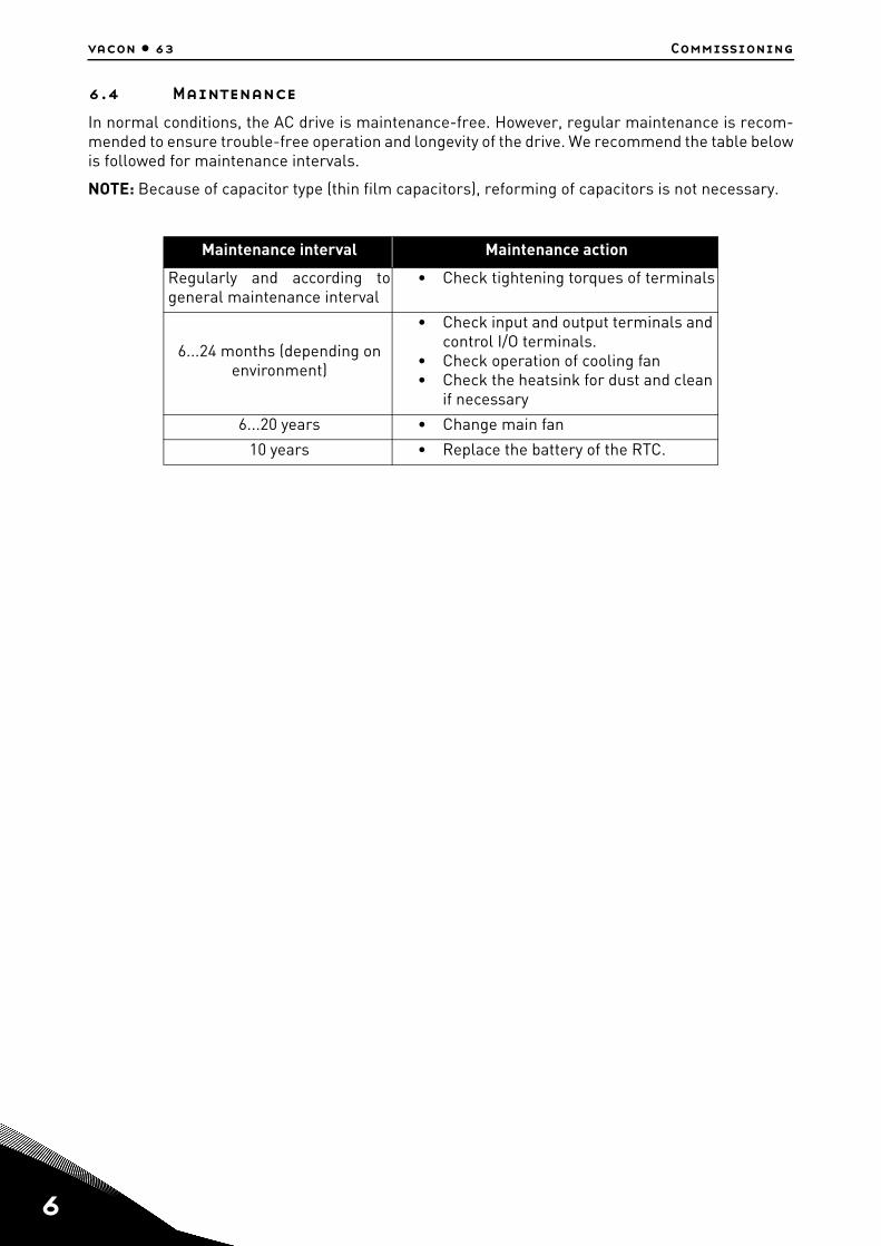
6.4 MaintenanceIn normal conditions, the AC drive is maintenance-free. However, regular maintenance is recom-mended to ensure trouble-free operation and longevity of the drive. We recommend the table belowis followed for maintenance intervals.
NOTE: Because of capacitor type (thin film capacitors), reforming of capacitors is not necessary.
Maintenance interval Maintenance action
Regularly and according togeneral maintenance interval
• Check tightening torques of terminals
6...24 months (depending on environment)
• Check input and output terminals and control I/O terminals.
• Check operation of cooling fan• Check the heatsink for dust and clean
if necessary
6...20 years • Change main fan
10 years • Replace the battery of the RTC.
Technical data vacon •
7. TECHNICAL DATA
7.1 AC drive power ratings
7.1.1 Mains voltage 3AC 208-240V
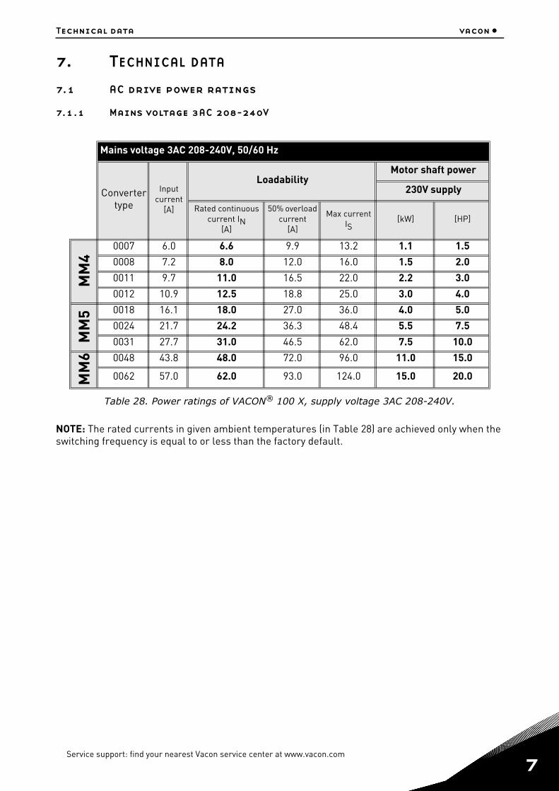
Table 28. Power ratings of VACON® 100 X, supply voltage 3AC 208-240V.
NOTE: The rated currents in given ambient temperatures (in Table 28) are achieved only when the switching frequency is equal to or less than the factory default.
Mains voltage 3AC 208-240V, 50/60 Hz
Converter type
Input current
[A]
LoadabilityMotor shaft power
230V supply
Rated continuous current IN
[A]
50% overload current
[A]
Max current IS
[kW] [HP]
MM
4
0007 6.0 6.6 9.9 13.2 1.1 1.5
0008 7.2 8.0 12.0 16.0 1.5 2.0
0011 9.7 11.0 16.5 22.0 2.2 3.0
0012 10.9 12.5 18.8 25.0 3.0 4.0
MM
5 0018 16.1 18.0 27.0 36.0 4.0 5.0
0024 21.7 24.2 36.3 48.4 5.5 7.5
0031 27.7 31.0 46.5 62.0 7.5 10.0
MM
6 0048 43.8 48.0 72.0 96.0 11.0 15.0
0062 57.0 62.0 93.0 124.0 15.0 20.0
Service support: find your nearest Vacon service center at www.vacon.com 7

7
vacon • 65 Technical data
7.1.2 Mains voltage 3AC 380-480/500V
NOTE: The rated currents in given ambient temperatures (in Table 29 and Table 30) are achieved only when the switching frequency is equal to or less than the factory default.
Mains voltage 3AC 380-480/500V, 50/60 Hz
Converter type
Input current
[A]
LoadabilityMotor shaft power
400V 480V
Rated continuous current IN
[A]
50% overload current
[A]
Max current IS
[kW] [HP]
MM
4
0003 3.4 3.4 5.1 6.8 1.1 1.5
0004 4.6 4.8 7.2 9.6 1.5 2.0
0005 5.4 5.6 8.4 11.2 2.2 3.0
0008 8.1 8.0 12.0 16.0 3.0 5.0
0009 9.3 9.6 14.4 19.2 4.0 5.0
0012 11.3 12.0 18.0 24.0 5.5 7.5
MM
5 0016 15.4 16.0 24.0 32.0 7.5 10.0
0023 21.3 23.0 34.5 46.0 11.0 15.0
0031 28.4 31.0 46.5 62.0 15.0 20.0
MM
6 0038 36.7 38.0 57.0 76.0 18.5 25.0
0046 43.6 46.0 69.0 92.0 22.0 30.0
0061 58,2 61.0 91.5 122.0 30.0 40.0
Table 29. Power ratings of VACON® 100 X, supply voltage 3AC 380-480/500V, high overload.
Mains voltage 3AC 380-480/500V, 50/60 Hz
Converter type
Input current
[A]
LoadabilityMotor shaft power
400V 480V
Rated continuous current IN
[A]
10% overload current
[A]
Max current IS
[kW] [HP]
MM
6
0072 67.5 72.0 80.0 108.0 37.0 50.0
Table 30. Power ratings of VACON® 100 X, supply voltage 3AC 380-480/500V, low overload.

Technical data vacon •
7.1.3 Definitions of overloadability
High overload= Following continuous operation at rated output current IN, the converter supplies 150% * IN for 1 min, followed by a period of at least 9 min at IN or below.
Example: If the duty cycle requires 150% rated current for 1 min in every 10 min, the remaining 9 min must be at rated current IN or less.
Figure 43. High overload.
Low overload= Following continuous operation at rated output current IN, the converter supplies 110% * IN for 1 min, followed by a period of at least 9 min at IN or below.
Example: If the duty cycle requires 110% rated current for 1 min in every 10 min, the remaining 9 min must be at rated current IN or less.
Figure 44. Low overload.
NOTE! For more information, please refer to IEC61800-2 (IEC:1998) Standard.
IN
IN*150%
1 min 9 min
IN*150%
Current
Time
IN
IN*110%
1 min 9 min
IN*110%
Current
Time
Service support: find your nearest Vacon service center at www.vacon.com 7

7
vacon • 67 Technical data
7.2 Brake resistor ratingsMake sure that the resistance is higher than the minimum resistance defined. The power handling capacity must be sufficient for the application.
Recommended minimum brake resistor values for VACON® 100 X AC drives:
Mains Voltage 3AC 208-240V, 50/60 Hz
Frame TypeMinimum Resistance
recommended[ohm]
Brake power @405 VDC
[kW]
MM4
0007 25 6.6
0008 25 6.6
0011 25 6.6
0012 25 6.6
MM5
0018 15 10.9
0024 15 10.9
0031 10 16.4
MM60048 8 20.5
0062 8 20.5
Table 31. Brake resistor ratings, 208-240V.
Mains Voltage 3AC 380-480/500V, 50/60 Hz
Frame TypeMinimum Resistance
recommended[ohm]
Brake power @845 VDC[kW]
MM4
0003 50 14.3
0004 50 14.3
0005 50 14.3
0008 50 14.3
0009 50 14.3
0012 50 14.3
MM5
0016 30 23.8
0023 30 23.8
0031 20 35.7
MM6
0038 15 47.6
0046 15 47.6
0061 15 47.6
0072 15 47.6
Table 32. Brake resistor ratings, 380-480/500V.

Technical data vacon •
7.3 VACON® 100 X - technical data
Mains connection
Input voltage Uin
3AC 208…240V3AC 380...480V3AC 380...500V
Input voltage tolerance -15%...+10% continuously
Input frequency 50/60 Hz
Protection class I
Input frequency tolerance 47.5...66 Hz
Connection to mains Once per minute or less
Starting delay <7 s
Supply network TN- and IT-network (cannot be used with corner earthed network)
Short-circuit current Max. short-circuit current has to be < 100kA
Motor connection
Output voltage 3AC 0... Uin
Rated output currentIN: Ambient temperature max. +40°C. See Table 28, Table 29 and Table 30.
Overload output current
1.5 x IN (1 min/10 min);1.1 x IN (1 min/10 min) only for MM6 0072.See Table 28, Table 29 and Table 30.
Starting output currentIS for 2 s every 20 s. See Table 28, Table 29 and Table 30.
Output frequency 0…320 Hz (standard)
Frequency resolution 0.01 Hz
Protection class I
Motor characteristics AC squirrel cage motorsPermanent magnet motors
Cable type Screened motor cable
Cable maximum length(full EMC compliance) C2: 15m
Control characteristics
Switching frequencyProgrammable 1.5…16 kHz; Default: 6 kHz (MM4 and MM5); 4 kHz (MM6)Automatic switching frequency derating in case of overheating
Frequency referenceAnalogue inputPanel reference
Resolution 0.1% (10-bit), accuracy ±1%Resolution 0.01 Hz
Field weakening point 8…320 Hz
Acceleration time 0.1…3000 sec
Deceleration time 0.1…3000 sec
Braking Brake chopper standard in all framesExternal brake resistor optional
Table 33. VACON® 100 X technical data.
Service support: find your nearest Vacon service center at www.vacon.com 7

7
vacon • 69 Technical data
Control connections See chapter 5.
Communication interface
Fieldbus
Standard: Serial communication (RS485/Mod-bus); Ethernet IP, Profinet IO, Modbus TCP, Bac-net IPOptional: CanOpen; Profibus DP, DeviceNet, Lon-works, AS-interface
Status indicators Drive status indicators (LED) on top side (POWER, RUN, FAULT, READY)
Ambient conditions
Ambient operating temperature -10°C …+40°C
Extended temperature range up to 60°C with current derating (see chapter 1.8)
Storage temperature -40°C…+70°C
Relative humidity 0 to 100% RH
Pollution degree
PD2 used for PCB design.However the drives are suitable for outdoor use because of dust-tight enclosure to numeral 6 [acc. to IEC 60529].
Altitude 100% load capacity (no derating) up to 1,000m;derating 1%/100m at 1,000...3,000m
Stationary vibration:sinusoidal
3 Hz ≤ f ≤ 8,72 Hz: 10 mm8,72 Hz ≤ f ≤ 200 Hz: 3g[3M7 acc. to IEC 60721-3-3]
Shock/Bump 25g / 6 ms[3M7 acc. to IEC 60721-3-3]
Degree of protection IP66/Type 4X
Noise Level Average noise level (min-max) in dB (A)
The sound pressure depends on the cooling fan speed, which is controlled in accordance with the drive temperature.MM4: 45-56MM5: 57-65MM6: 63-72
Directives
EMC 2004/108/EC
Low Voltage Directive 2006/95/EC
RoHS 2002/95/EC
WEEE 2012/19/EC
Standards
Immunity EN61800-3 (2004), 1st and 2nd environment
Emissions EN61800-3 (2004), Category C2The drive can be modified for IT-networks.
THD EN61000-3-12 (see chapter 1.9)
Safety EN 61800-5-1
Production quality ISO 9001
Table 33. VACON® 100 X technical data.

Technical data vacon •
Approvals
Functional Safety TÜV - Tested
Electrical Safety TÜV - Tested
EMC TÜV - Tested
USA, Canada cULus approval, file number E171278
Declaration of Conformity
Korea KC mark
Australia C-tick Declaration of Conformity Registration number E2204
Europe EC Declaration of Conformity
Protections
Undervoltage trip limit
Depends on supply voltage (0,8775*supply volt-age):Supply voltage 240 V: Trip limit 211 VSupply voltage 400 V: Trip limit 351 VSupply voltage 480 V: Trip limit 421 V
Overvoltage fault protec-tion Yes
Earth fault protection Yes
Mains supervision Yes
Motor phase supervision Yes
Overcurrent protection Yes
Unit overtemperature protection Yes
Motor overload protec-tion
Yes. These devices provide motor overload protec-tion at 105% of full load amperes.
Motor stall protection Yes
Motor underload protec-tion Yes
Short-circuit protection of +24V and +10V refer-ence voltages
Yes
Thermal motor protec-tion Yes (by PTC)
Table 33. VACON® 100 X technical data.
Service support: find your nearest Vacon service center at www.vacon.com 7

7
vacon • 71 Technical data
7.3.1 Technical information on control connections
Standard I/O
Terminal Signal Technical information
1 Reference output +10V, +3%; Maximum current 10 mA
2 Analogue input, voltage or current
Analogue input channel 10-20 mA (Ri =250 Ω)0-10 V (Ri=200kΩ) Resolution 0.1%, accuracy ±1%Selection V/mA with dip-switches (see chapter 5). Default 0-10VShort-circuited protected.
3 Analogue input common Differential input if not connected to ground; Allows ±20V differential mode voltage to GND
4 Analogue input, voltage or current
Analogue input channel 20-20 mA (Ri =250 Ω)0-10 V (Ri=200kΩ) Resolution 0.1%, accuracy ±1%Selection V/mA with dip-switches (see chapter 5).Default 0-20mAShort-circuited protected.
5 Analogue input common Differential input if not connected to ground; Allows 20V differential mode voltage to GND
6 24V aux. voltage+24V, ±10%, max volt. ripple < 100mVrms; max. 250mAShort-circuit protected
7 I/O groundGround for reference and controls (connected internally to frame earth through 1MΩ)
8 Digital input 1 Positive or negative logicRi = min. 5kΩ18…30V = "1"0...5V = “0”
9 Digital input 2
10 Digital input 3
11 Common A for DIN1-DIN6.Digital inputs can be isolated from ground, see chapter 5.Default: connected to ground.
12 24V aux. voltage Same as terminal 6.
13 I/O groundGround for reference and controls (connected internally to frame earth through 1MΩ)
14 Digital input 4 Positive or negative logicRi = min. 5kΩ18…30V = "1"0...5V = “0”
15 Digital input 5
16 Digital input 6
17 Common A for DIN1-DIN6.Digital inputs can be isolated from ground, see chapter 5.Default: connected to ground.
18 Analogue output, voltage or current
Analogue output channel 10-20 mA (RL<500 Ω)
0-10 V (RL>1kΩ) Resolution 0.1%, accuracy ±2%Selection V/mA with dip-switches (see chapter 5).Default 0-20mAShort-circuited protected.
19 Analogue output common
30 24V auxiliary input voltageCan be used with an external power supply (with a current limiter or fuse protected) to supply the control unit and fieldbus for backup purposes. Dimensioning: max. 1000mA/control unit.
Table 34. Technical information on standard I/O terminals.

Technical data vacon •
A RS485 Differential receiver/transmitterSet bus termination with dip switches (see page 50).Default: but termination disconnected.B RS485
Relays Relays with two change-over contact (SPDT) and a PTC thermistor input.5,5 mm isolation between channels.
Terminal Signal Technical information
21
Relay output 1*
* If 230VAC is used as control voltage from the output relays, the control circuitry must be powered with a separate isolation transformer to limit short circuit current and overvoltage spikes. This is to prevent welding on the relay contacts. Refer to standard EN 60204-1, section 7.2.9
Switching capacity 24VDC/8A250VAC/8A125VDC/0.4A
Min.switching load 5V/10mA
22
23
24Relay output 2*
Switching capacity 24VDC/8A250VAC/8A125VDC/0.4A
Min.switching load 5V/10mA
25
26
28Thermistor input Rtrip = 4.7 kΩ (PTC); Measuring voltage 3.5V
29
Table 35. Technical information on Relay and thermistor terminals.
Standard I/O
Terminal Signal Technical information
Table 34. Technical information on standard I/O terminals.
Service support: find your nearest Vacon service center at www.vacon.com 7

7
vacon • 73 Technical data

Options vacon • 74
8. OPTIONS
The options available for VACON® 100 X are described below.
8.1 Mains switchThe purpose of the Mains switch is to disconnect the VACON® 100 X from the mains when, for ex-ample, service actions are needed. The mains switch is available as option and it can be integratedin the drive. The switch can be mounted on either side of the drive. See Figure 45.
Figure 45. The mains switch mounted on either side of the drive, MM4 example.
8.1.1 Installation
Figure 46. Disconnect the cable entry plate: example for MM5.
1• Remove the cable entry plate from the drive on the left-hand-side if the mains
switch must be mounted on this side. Otherwise remove the cable entry platefrom the right-hand-side. See the Figure 46.
Service support: find your nearest Vacon service center at www.vacon.com 8

8
vacon • 75 Options
Figure 47. Cable entry plate from the bottom side of the drive.
Figure 48. Powerhead separated from the terminal box.
2 • Remove the cable entry plate from the bottom side of the terminal box by loos-ing the six screws. Cables pass through this inlet hole.
3 • Remove the powerhead from the terminal box by loosing the screws on the top side of the drive.

Options vacon • 76
Figure 49. Connection of the supply cable to the Mains switch (right-hand-side example).
4• Connect the supply cable to the Mains switch passing through the cable entry
plate of the bottom side (use the cable gland for sealing the cable to the glandplate) and then through the terminal box as shown in the figure below.
5 • Connect the cables from the Mains switch to the terminal box. The cables haveto be connected to the terminals L1, L2 and L3.
6 • Place the Mains switch plate with the cables in the groove and fix it with itsscrews.
7 • Place the cable entry plate with the other cables (motor cable, brake cable, I/Ocables) in the groove on the bottom side of the drive and fix it with its screws.
Service support: find your nearest Vacon service center at www.vacon.com 8

8
vacon • 77 Options
Figure 50. Mains switch, cable entry and cables connected.
Figure 51. Mount the powerhead on the terminal box.
8 • Mount the powerhead on the terminal box with its screws: the installation pro-cess has been completed. See Figure 51.

Options vacon • 78
8.2 Control KeypadThe control keypad is the interface between the VACON® 100 X frequency converter and the user.With the control keypad it is possible to control the speed of a motor, to supervise the state of theequipment and to set the frequency converter's parameters.
The keypad is an option and can be delivered separately. The option includes the keypad, the keypadholder and three screws. You can use one screw to fix the keypad holder to the drive or three screwsto fix the keypad holder to an enclosure/cabinet or any special housing for the drive in which youwant to have a remote keypad control available.
8.2.1 Mounting onto the drive
Figure 52. Drive and the optional keypad kit.
Service support: find your nearest Vacon service center at www.vacon.com 8

8
vacon • 79 Options
8.2.2 Installation
Figure 53. Disconnection of the HMI cap from the drive.
Figure 54. Installation of the keypad holder on the powerhead.
1 • Remove the HMI cap from the drive as shown in the Figure 53.
2• Install the keypad holder with a screw as shown in the Figure 54. The metal
sheets of the keypad holder have to be mounted under the fan holder as shown in the following figures.

Options vacon • 80
Figure 55. Mounting of the keypad.
Figure 56. Keypad mounted onto the drive. Tighten the fixing screws of the cable connector to the enclosure of the drive. This is to keep the high IP66 protection degree of the drive.
3 • Connect the keypad to the drive and plug the cable on the HMI connector as shown in the Figure 55 and in the Figure 56.
Service support: find your nearest Vacon service center at www.vacon.com 8

8
vacon • 81 Options
8.2.3 Wall-mountingThe keypad can be mounted on the wall in a convenient location by using the same keypad holder and three screws provided with the keypad option kit.
Figure 57. Fix the keypad holder with three screws to the wall.
1 • Fix the keypad holder with three screws to the wall.
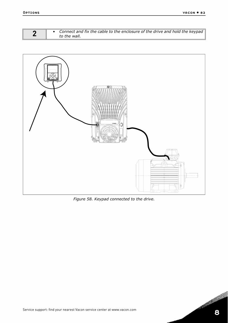
Options vacon • 82
Figure 58. Keypad connected to the drive.
2 • Connect and fix the cable to the enclosure of the drive and hold the keypad to the wall.
Service support: find your nearest Vacon service center at www.vacon.com 8

8
vacon • 83 Options
8.2.4 Graphical and Text keypadThere are two keypad types you can choose for your user interface: keypad with graphical display and keypad with text segment display (text keypad).
The button section of the keypad is identical for both keypad types.
Figure 59. Keypad buttons.
9086.emf
FUNCT
Scroll menu upIncrease value
Scroll menu downDecrease value
Move cursor left Move cursor right
Move backward in menuExit edit modeReset faults with long press
Change control place
Access control pageChange direction
Stop button Start button
Enter active level/itemConfirm selection

Options vacon • 84
8.2.5 VACON® keypad with graphical displayThe graphical keypad features an LCD display and 9 buttons.
8.2.5.1 Keypad displayThe keypad display indicates the status of the motor and the drive and any irregularities in motor ordrive functions. On the display, the user sees information about his present location in the menustructure and the item displayed.
8.2.5.2 Main menu
The data on the control keypad are arranged in menus and submenus. Use the Up and Down arrowsto move between the menus. Enter the group/item by pressing the OK button and return to the for-mer level by pressing the Back/Reset button.
The Location field indicates your current location. The Status field gives information about thepresent status of the drive. See Figure 60.
Figure 60. Main menu.
8.2.5.3 Using the graphical keypadEditing values
The selectable values can be accessed and edited in two different ways on the graphical keypad.
Parameters with one valid value
Typically, one parameter is set one value. The value is selected either from a list of values (see ex-ample below) or the parameter is given a numerical value from a defined range (e.g. 0.00...50.00 Hz).
Change value of a parameter following the procedure below:
1. Locate the parameter.
2. Enter the Edit mode.
3. Set new value with the arrow buttons up/down. You can also move from digit to digit with the arrow buttons left/right if the value is numerical and then change the value with the arrow but-tons up/down.
4. Confirm change with OK button or ignore change by returning to previous level with Back/Reset button.
Location field
Status field
(Parameter ID number
Main Menu
Quick Setup( 17 )
Parameters
( 12 )
STOP READY I/O
ID: M1
( 5 )Monitor
Activated group/item. Press OK to enter.
Number of items in the group
STOP/RUN Status fieldREADY/NOT READY/FAULT
Control place:PC/IO/KEYPAD/FIELDBUS
ALARM
and current menu location)
Direction
Service support: find your nearest Vacon service center at www.vacon.com 8
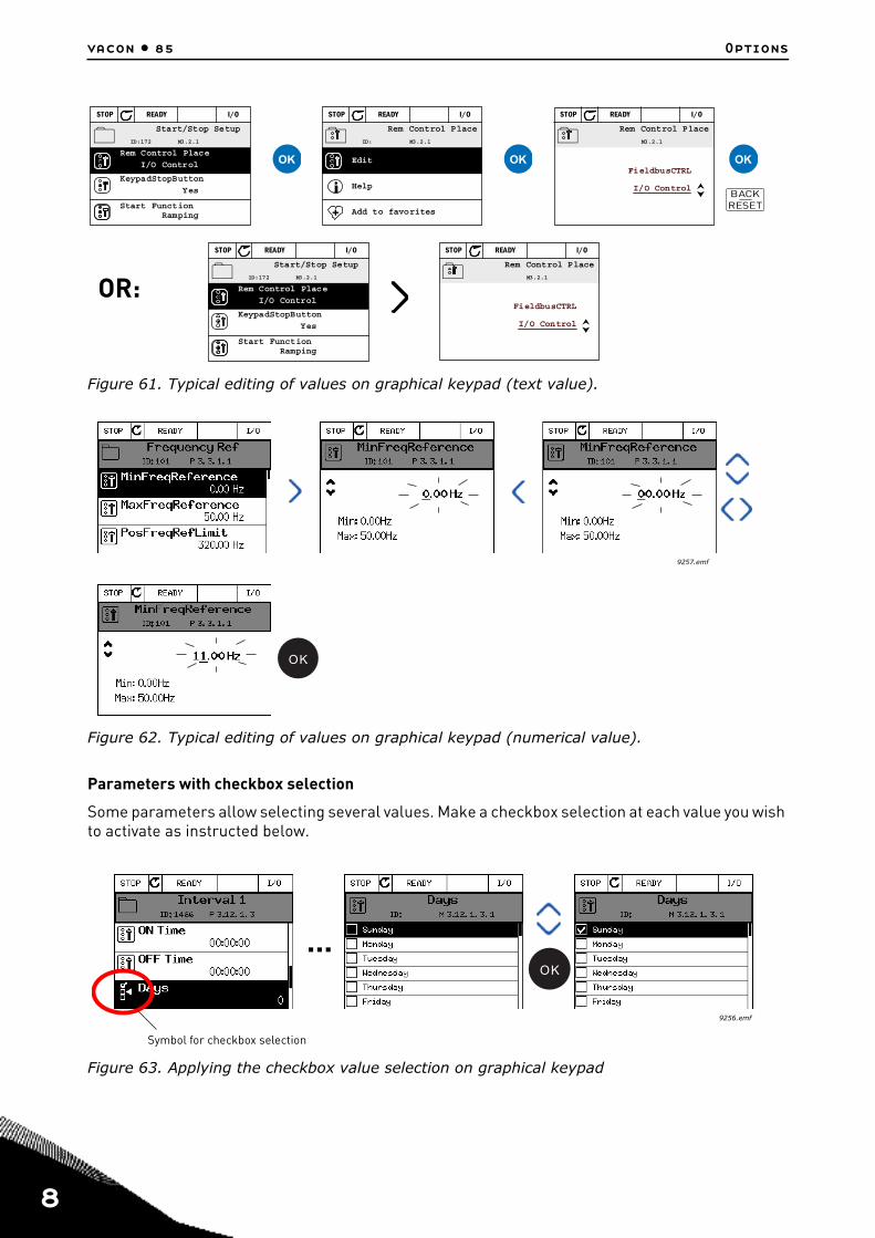
8
vacon • 85 Options
Figure 61. Typical editing of values on graphical keypad (text value).
Figure 62. Typical editing of values on graphical keypad (numerical value).
Parameters with checkbox selection
Some parameters allow selecting several values. Make a checkbox selection at each value you wish to activate as instructed below.
Figure 63. Applying the checkbox value selection on graphical keypad
Start/Stop Setup
Rem Control Place
I/O Control
KeypadStopButton
Yes
Start FunctionRamping
STOP READY I/O
ID:172 M3.2.1 Edit
Help
Add to favorites
Rem Control Place
STOP READY I/O
ID: M3.2.1 Rem Control Place
STOP READY I/O
M3.2.1
I/O Control
FieldbusCTRL
Start/Stop Setup
Rem Control Place
I/O Control
KeypadStopButton
Yes
Start FunctionRamping
STOP READY I/O
ID:172 M3.2.1 Rem Control Place
STOP READY I/O
M3.2.1
I/O Control
FieldbusCTRL
OR:
OK OK OK
BACKRESET
9257.emf
OK
9256.emf
...OK
Symbol for checkbox selection
Options vacon • 86
Resetting fault
Instructions for how to reset a fault can be found in chapter 8.2.7.
Function button
The FUNCT button is used for four functions:
1. to quickly access the Control page, 2. to easily change between the Local (Keypad) and Remote control places,3. to change the rotation direction and4. to quickly edit a parameter value.
Control places
The control place is the source of control where the drive can be started and stopped. Every control place has its own parameter for selecting the frequency reference source. The Local control place is always the keypad. The Remote control place is determined by parameter P3.2.1 (I/O or Field-bus). The selected control place can be seen on the status bar of the keypad.
Remote control place
I/O A, I/O B and Fieldbus can be used as remote control places. I/O A and Fieldbus have the lowest priority and can be chosen with parameter P3.2.1 (Rem Control Place). I/O B, again, can bypass the remote control place selected with parameter P3.2.1 using a digital input. The digital input is se-lected with parameter P3.5.1.7 (I/O B Ctrl Force).
Local control
Keypad is always used as control place while in local control. Local control has higher priority than remote control. Therefore, if, for example, bypassed by parameter P3.5.1.7 through digital input while in Remote, the control place will still switch to Keypad if Local is selected. Switching between Local and Remote Control can be done by pressing the FUNCT-button on the keypad or by using the "Local/Remote" (ID211) parameter.
Changing control places
Change of control place from Remote to Local (keypad).
1. Anywhere in the menu structure, push the FUNCT button.2. Push the Arrow up or the Arrow down button to select Local/Remote and confirm with the OK
button.3. On the next display, select Local or Remote and again confirm with the OK button.4. The display will return to the same location as it was when the FUNCT button was pushed. How-
ever, if the Remote control place was changed to Local (Keypad) you will be prompted for key-pad reference.
Service support: find your nearest Vacon service center at www.vacon.com 8

8
vacon • 87 Options
Figure 64. Changing control places.
Accessing the control page
The Control page is meant for easy operation and monitoring of the most essential values.
1. Anywhere in the menu structure, push the FUNCT button. 2. Push the Arrow up or the Arrow down button to select Control page and confirm with the OK
button. 3. The control page appears
If keypad control place and keypad reference are selected to be used you can set the Keypad Reference after having pressed the OK button. If other control places or reference values are used the display will show Frequency reference which is not editable. The other values on the page are Multimonitoring values. You can choose which values appear here for monitoring.
Figure 65. Accessing Control page.
Main Menu
Parameters
( 15 )Diagnostics
STOP READY Keypad
ID: M1
( 7 )Monitor
( 6 )
ID:
Choose action
STOP Ready Keypad
ID:1805
Local/Remote
Control page
Change direction
?
Remote
ID:
Local/Remote
STOP READY Keypad
ID:211
Remote
Local
Main Menu
Parameters
( 15 )Diagnostics
STOP READY I/O
ID: M1
( 7 )Monitor
( 6 )
FUNCT
OK
OK
9161
.em
f
Main Menu
Parameters
( 15 )Diagnostics
STOP READY I/O
ID: M1
( 7 )Monitor
( 6 )
ID:
Choose action
STOP Ready Keypad
ID:1805
Local/Remote
Control page
Change direction
STOP READY Keypad
( 6 )
Keypad Reference
0.00 HzOutput Frequency
0.00HzMotor Current
0.00A
Motor Torque
0.00%
0.00%
Motor Power
ID:184
Keypad
0.00 HzOutput Frequency
0.00HzMotor Current
0.00A
Motor Torque
0.00%
0.00%
Motor Power
STOP READY Keypad
( 6 )
ID:168
Keypad Reference
0.00 HzOutput Frequency
0.00HzMotor Current
0.00A
Motor Torque
0.00%
0.00%
Motor Power
FUNCT
OK
OK
OK
9162.emf

Options vacon • 88
Changing direction
Rotation direction of the motor can quickly be changed by applying the FUNCT button. NOTE! Chang-ing direction command is not visible in the menu unless the selected control place is Local.
1. Anywhere in the menu structure, push the Funct button.2. Push the Arrow up or the Arrow down button to select Change direction and confirm with the OK
button.3. Then choose the direction you wish to run the motor to. The actual rotation direction is blinking.
Confirm with the OK button.4. The rotation direction changes immediately and the arrow indication in the status field changes.
Figure 66. Changing direction.
Quick edit
Through the Quick edit functionality you can quickly access the desired parameter by entering the parameter’s ID number.
1. Anywhere in the menu structure, push the FUNCT button. 2. Push the Arrow up or the Arrow down buttons to select Quick Edit and confirm with the OK but-
ton. 3. Then enter the ID number of parameter or monitoring value you wish to access. Press OK but-
ton to confirm. 4. Requested Parameter/Monitoring value appears on the display (in editing/monitoring mode.)
Main Menu
Parameters
( 15 )Diagnostics
STOP READY I/O
ID: M1
( 7 )Monitor
( 6 )
ID:
Choose action
RUN Ready Keypad
ID:1805
Local/Remote
Control page
Change direction
ID:
Choose action
RUN Ready Keypad
ID:1805
Forward
Reverse
Main Menu
Parameters
( 15 )Diagnostics
STOP READY I/O
ID: M1
( 7 )Monitor
( 6 )
FUNCT
OK OK
9163
.ai
Service support: find your nearest Vacon service center at www.vacon.com 8
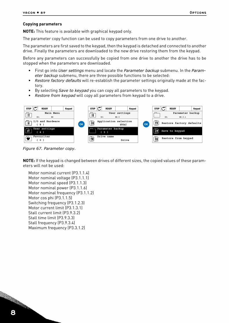
8
vacon • 89 Options
Copying parameters
NOTE: This feature is available with graphical keypad only.
The parameter copy function can be used to copy parameters from one drive to another.
The parameters are first saved to the keypad, then the keypad is detached and connected to anotherdrive. Finally the parameters are downloaded to the new drive restoring them from the keypad.
Before any parameters can successfully be copied from one drive to another the drive has to bestopped when the parameters are downloaded.
• First go into User settings menu and locate the Parameter backup submenu. In the Param-eter backup submenu, there are three possible functions to be selected:
• Restore factory defaults will re-establish the parameter settings originally made at the fac-tory.
• By selecting Save to keypad you can copy all parameters to the keypad.• Restore from keypad will copy all parameters from keypad to a drive.
Figure 67. Parameter copy.
NOTE: If the keypad is changed between drives of different sizes, the copied values of these param-eters will not be used:
Motor nominal current (P3.1.1.4)Motor nominal voltage (P3.1.1.1)Motor nominal speed (P3.1.1.3)Motor nominal power (P3.1.1.6)Motor nominal frequency (P3.1.1.2)Motor cos phi (P3.1.1.5)Switching frequency (P3.1.2.3)Motor current limit (P3.1.3.1)Stall current limit (P3.9.3.2)Stall time limit (P3.9.3.3)Stall frequency (P3.9.3.4)Maximum frequency (P3.3.1.2)
STOP READY Keypad
Application selection
HVAC
User settings
Drive name
Drive
Parameter backup( 3 )
ID: M6.5
STOP READY Keypad
Restore factory defaults
Parameter backup
Restore from keypad
Save to keypad
ID: M6.5.1
STOP READY Keypad
I/O and Hardware( 8 )
Main Menu
Favourites
( 0 )
User settings( 4 )
ID: M6
OK OK

Options vacon • 90
Help texts
The graphical keypad features instant help and information displays for various items.
All parameters offer an instant help display. Select Help and press the OK button.
Text information is also available for faults, alarms and the startup wizard.
Figure 68. Help text example.
Adding item to favourites
You might need to refer to certain parameter values or other items often. Instead of locating them one by one in the menu structure, you may want to add them to a folder called Favorites where they can easily be reached.
To add an item to the Favorites.
Figure 69. Adding item to Favorites.
( 6 )
Digital Inputs
Ctrl Signal 1 A
Ctrl Signal 1 B
STOP READY I/O
ID:403 M3.5.1.1
Ctrl Signal 2 A
( 6 )
Add to favorites
STOP READY I/O
ID:403 M3.5.1.1
Ctrl signal 1 A
Edit
Help
Start Signal 1 for control PlaceI/O A. Start Signal 1functionality chosen with I/O ALogic in Start/Stop Setup Menu.
STOP READY I/O
Ctrl signal 1 A
ID:403 M3.5.1.1
OK OK
Basic Settings
Motor Nom Voltg230.00 V
Motor Nom Speed
1430 rpm
STOP READY I/O
Motor Nom Freq50.00 Hz
Edit
Help
Motor Nom Freq
STOP READY I/O
Add to favorites
Motor Nom Freq
was added tofavorites. Press OKto continue.
STOP READY I/O
OK OK
Service support: find your nearest Vacon service center at www.vacon.com 8

8
vacon • 91 Options
8.2.6 VACON® keypad with text segment displayYou can also choose a Keypad with text segment display (Text keypad) for your user interface. Ithas mainly the same functionalities as the keypad with graphical display although some of theseare somewhat limited.
8.2.6.1 Keypad displayThe keypad display indicates the status of the motor and the drive and any irregularities in motor ordrive functions. On the display, the user sees information about his present location in the menustructure and the item displayed. If the text on the text line is too long to fit in the display, the textwill scroll from left to right to reveal the whole text string.
8.2.6.2 Main menu
The data on the control keypad are arranged in menus and submenus. Use the Up and Down arrowsto move between the menus. Enter the group/item by pressing the OK button and return to the for-mer level by pressing the Back/Reset button.
Indicators: Status
Indicators: Alarm, Fault
Indicators: Direction
Indicators: Control place
Group or parameter name
Menu location

Options vacon • 92
8.2.6.3 Using the keypad
Editing values
Change value of a parameter following the procedure below:
1. Locate the parameter.
2. Enter the Edit mode by pressing OK.
3. Set new value with the arrow buttons up/down. You can also move from digit to digit with thearrow buttons left/right if the value is numerical and change then the value with the arrow but-tons up/down.
4. Confirm change with OK button or ignore change by returning to previous level with Back/Reset button.
Figure 70. Editing values.
Resetting fault
Instructions for how to reset a fault can be found in chapter 8.2.7.
Function button
The FUNCT button is used for four functions:
1. to quickly access the Control page, 2. to easily change between the Local (Keypad) and Remote control places, 3. to change the rotation direction and 4. to quickly edit a parameter value.
Control places
The control place is the source of control where the drive can be started and stopped. Every control place has its own parameter for selecting the frequency reference source. The Local control place is always the keypad. The Remote control place is determined by parameter P3.2.1 (I/O or Field-bus). The selected control place can be seen on the status bar of the keypad.
Remote control place
I/O A, I/O B and Fieldbus can be used as remote control places. I/O A and Fieldbus have the lowest priority and can be chosen with parameter P3.2.1 (Rem Control Place). I/O B, again, can bypass the remote control place selected with parameter P3.2.1 using a digital input. The digital input is se-lected with parameter P3.5.1.7 (I/O B Ctrl Force).
Local control
Keypad is always used as control place while in local control. Local control has higher priority thanremote control. Therefore, if, for example, bypassed by parameter P3.5.1.7 through digital inputwhile in Remote, the control place will still switch to Keypad if Local is selected. Switching betweenLocal and Remote Control can be done by pressing the FUNCT-button on the keypad or by using the"Local/Remote" (ID211) parameter.
BACKRESET
OKOK OK
Service support: find your nearest Vacon service center at www.vacon.com 8

8
vacon • 93 Options
Changing control places
Change of control place from Remote to Local (keypad).
1. Anywhere in the menu structure, push the FUNCT button.
2. Using the arrow buttons, select Local/Remote and confirm with the OK button.
3. On the next display, select Local or Remote and again confirm with the OK button.
4. The display will return to the same location as it was when the FUNCT button was pushed.However, if the Remote control place was changed to Local (Keypad) you will be prompted forkeypad reference.
Figure 71. Changing control places.
Accessing the control page
The Control page is meant for easy operation and monitoring of the most essential values.
1. Anywhere in the menu structure, push the FUNCT button. 2. Push the Arrow up or the Arrow down button to select Control page and confirm with the OK
button. 3. The control page appears
If keypad control place and keypad reference are selected to be used you can set the Keypad Reference after having pressed the OK button. If other control places or reference values are used the display will show Frequency reference which is not editable.
Figure 72. Accessing Control page.
FUNCT
OK OK
9169.emf
9170.emf
FUNCT
OK
OK

Options vacon • 94
Changing direction
Rotation direction of the motor can quickly be changed by applying the FUNCT button.NOTE! Chang-ing direction command is not visible in the menu unless the selected control place is Local.
1. Anywhere in the menu structure, push the Funct button.2. Push the Arrow up or the Arrow down button to select Change direction and confirm with the OK
button.3. Then choose the direction you wish to run the motor to. The actual rotation direction is blinking.
Confirm with the OK button.4. The rotation direction changes immediately and the arrow indication in the status field changes.
Quick edit
Through the Quick edit functionality you can quickly access the desired parameter by entering the parameter’s ID number.
1. Anywhere in the menu structure, push the FUNCT button.2. Push the Arrow up or the Arrow down buttons to select Quick Edit and confirm with the OK but-
ton.3. Then enter the ID number of parameter or monitoring value you wish to access. Press OK but-
ton to confirm.4. Requested Parameter/Monitoring value appears on the display (in editing/monitoring mode.)
Service support: find your nearest Vacon service center at www.vacon.com 8

8
vacon • 95 Options
8.2.7 Fault TracingWhen an unusual operating condition is detected by the AC drive control diagnostics, the drive ini-tiates a notification visible, for example, on the keypad. The keypad will show the code, the nameand a short description of the fault or alarm.
The notifications vary in consequence and required action. Faults make the drive stop and requirereset of the drive. Alarms inform of unusual operating conditions but the drive will continue run-ning. Info may require resetting but do not affect the functioning of the drive.
For some faults you can program different responses in the application. See parameter group Pro-tections.
The fault can be reset with the Reset button on the control keypad or via the I/O terminal. The faultsare stored in the Fault history menu which can be browsed. The different fault codes you will findin the table below.
NOTE: When contacting distributor or factory because of a fault condition, always write down alltexts and codes on the keypad display.
Fault appears
When a fault appears and the drive stops examine the cause of fault, perform the actions advisedhere and reset the fault as instructed below.
1. With a long (1 s) press on the Reset button on the keypad or
2. By entering the Diagnostics Menu (M4), entering Reset faults (M4.2) and selecting Reset faultsparameter.
3. For keypad with LCD display only: By selecting value Yes for the parameter and clicking OK.
Figure 73. Diagnostic menu with graphical keypad.
Figure 74. Diagnostic menu with text keypad.
Main Menu
( 5 )MonitorParameters
( 12 )Diagnostics
( 6 )
ID: M4
STOP READY I/O
Diagnostics
Active faults
( 0 )
Fault history
( 39 )
ID: M4.1
STOP READY I/O
Reset faults
Reset faults
Reset faults
Help
ID: M4.2
STOP READY I/O
OK OK
OKOK

Options vacon • 96
8.2.7.1 Fault HistoryIn menu M4.3 Fault history you find the maximum number of 40 occurred faults. On each fault in the memory you will also find additional information, see below.
Figure 75. Fault history menu with graphical keypad.
Figure 76. Fault history menu with text keypad.
Diagnostics
Active faults
( 0 )
Reset faults
Fault history
( 39 )
ID: M4.1
STOP READY I/O
!!!
Fault history
External Fault
Fault old
51
891384s
External Fault
Fault old
51
871061s
Device removed
Info old
39
862537s
ID:
STOP READY I/O
!Device removed
ID: M4.3.3.2
Code 39
ID 380
State Info old
Date 7.12.2009
Time 04:46:33
Operating time 862537s
STOP READY I/O
OK
OK OK
Service support: find your nearest Vacon service center at www.vacon.com 8

8
vacon • 97 Options
8.2.7.2 Fault codes
Fault code
FaultID Fault name Possible cause Remedy
1
1Overcurrent (hardware fault)
AC drive has detected too high a cur-rent (>4*IH) in the motor cable:
• sudden heavy load increase• short circuit in motor cables• unsuitable motor
Check loading.Check motor.Check cables and connections.Make identification run.Check ramp times.
2Overcurrent (software fault)
2
10Overvoltage (hardware fault)
The DC-link voltage has exceeded the limits defined.
• too short a deceleration time• brake chopper is disabled• high overvoltage spikes in supply• Start/Stop sequence too fast
Make deceleration time longer. Use brake chopper or brake resistor (available as options).Activate overvoltage controller.Check input voltage.
11Overvoltage (soft-ware fault)
3
20Earth fault (hard-ware fault)
Current measurement has detected that the sum of motor phase current is not zero.
• insulation failure in cables or motor
Check motor cables and motor.21
Earth fault (soft-ware fault)
5 40 Charging switch
The charging switch is open, when the START command has been given.
• faulty operation• component failure
Reset the fault and restart.Should the fault re-occur, con-tact the distributor near to you.
7 60 Saturation
Various causes:• defective component• brake resistor short-circuit or
overload
Cannot be reset from keypad. Switch off power.DO NOT RE-CONNECT POWER!Contact factory.If this fault appears simultane-ously with F1, check motor cables and motor.
Table 36. Fault codes and descriptions.

Options vacon • 98
8
600
System fault
Communication between control board and power unit has failed.
Reset the fault and restart.Should the fault re-occur, con-tact the distributor near to you.
601Communication between control board and power unit has interference, but it is still working.
602 Watchdog has reset the CPU
603Voltage of auxiliary power in power unit is too low.
604Phase fault: Voltage of an output phase does not follow the reference
605CPLD has faulted but there is no detailed information about the fault
606Control and power unit software are incompatible
Update software. Should the fault re-occur, contact the dis-tributor near to you.
607Software version cannot be read. There is no software in power unit.
Update power unit software. Should the fault re-occur, con-tact the distributor near to you.
608
CPU overload. Some part of the soft-ware (for example application) has caused an overload situation. The source of fault has been suspended
Reset the fault and restart.Should the fault re-occur, con-tact the distributor near to you.
609Memory access has failed. For exam-ple, retain variables could not be restored.
610Necessary device properties cannot be read.
614 Configuration error.
647 Software error
Update software. Should the fault re-occur, contact the dis-tributor near to you.
648Invalid function block used in applica-tion. System software and application are not compatible.
649
Resource overload.Error when loading parameter initial values.Error when restoring parameters.Error when saving parameters.
9
80Undervoltage (fault)
DC-link voltage is under the voltage limits defined.
• most probable cause: too low a supply voltage
• AC drive internal fault• defect input fuse• external charge switch not
closedNOTE! This fault is activated only if the drive is in Run state.
In case of temporary supply voltage break reset the fault and restart the AC drive. Check the supply voltage. If it is ade-quate, an internal failure has occurred.Contact the distributor near to you.
81Undervoltage (alarm)
10 91 Input phase Input line phase is missing. Check supply voltage, fuses and cable.
Fault code
FaultID Fault name Possible cause Remedy
Table 36. Fault codes and descriptions.
Service support: find your nearest Vacon service center at www.vacon.com 8

8
vacon • 99 Options
11 100Output phase supervision
Current measurement has detected that there is no current in one motor phase.
Check motor cable and motor.
12
110Brake chopper supervision (hardware fault)
No brake resistor installed.Brake resistor is broken.Brake chopper failure.
Check brake resistor and cabling.If these are ok, the chopper is faulty. Contact the distributor near to you.111
Brake chopper saturation alarm
13 120AC drive undertempera-ture (fault)
Too low temperature measured in power unit’s heatsink or board. Heat-sink temperature is under -10°C.
Check the ambient tempera-ture
14
130AC drive overtemperature (fault, heatsink)
Too high temperature measured in power unit’s heatsink or board. Heat-sink temperature is over 100°C.
Check the correct amount and flow of cooling air.Check the heatsink for dust.Check the ambient tempera-ture.Make sure that the switching frequency is not too high in relation to ambient tempera-ture and motor load.
131AC drive overtemperature (alarm, heatsink)
132AC drive overtemperature (fault, board)
133AC drive overtemperature (alarm, board)
15 140 Motor stalled Motor is stalled. Check motor and load.
16 150Motor overtemperature Motor is overloaded.
Decrease motor load.If no motor overload exists, check the temperature model parameters.
17 160 Motor underload Motor is underloaded. Check load.
19
180Power overload (short-time supervision)
Drive power is too high. Decrease load.
181Power overload (long-time supervision)
25240 Motor control
fault
Start angle identification has failed. Reset the fault and restart.Should the fault re-occur, con-tact the distributor near to you.241 Generic motor control fault.
26 250Start-up prevented
Start-up of the drive has been pre-vented. Run request is ON when a new software (firmware or application), parameter setting or any other file, which has affects the operation of the drive, has been loaded to drive.
Reset the fault and stop the AC drive.Load the software and start the AC drive.
Fault code
FaultID Fault name Possible cause Remedy
Table 36. Fault codes and descriptions.
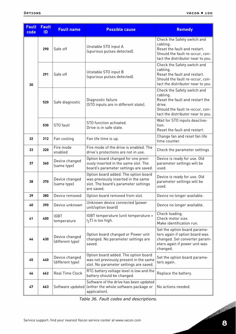
Options vacon • 100
30
290 Safe off Unstable STO input A(spurious pulses detected).
Check the Safety switch and cabling.Reset the fault and restart.Should the fault re-occur, con-tact the distributor near to you.
291 Safe off Unstable STO input B(spurious pulses detected).
Check the Safety switch and cabling.Reset the fault and restart.Should the fault re-occur, con-tact the distributor near to you.
520 Safe diagnostic Diagnostic failure(STO inputs are in different state).
Check the Safety switch and cabling.Reset the fault and restart the drive.Should the fault re-occur, con-tact the distributor near to you.
530 STO fault STO function activated.Drive is in safe state.
Wait for STO inputs deactiva-tion.Reset the fault and restart.
32 312 Fan cooling Fan life time is up. Change fan and reset fan life time counter.
33 320Fire mode enabled
Fire mode of the drive is enabled. The drive's protections are not in use. Check the parameter settings
37 360Device changed (same type)
Option board changed for one previ-ously inserted in the same slot. The board’s parameter settings are saved.
Device is ready for use. Old parameter settings will be used.
38 370Device changed (same type)
Option board added. The option board was previously inserted in the same slot. The board’s parameter settings are saved.
Device is ready for use. Old parameter settings will be used.
39 380 Device removed Option board removed from slot. Device no longer available.
40 390 Device unknown Unknown device connected (power unit/option board) Device no longer available.
41 400IGBT temperature
IGBT temperature (unit temperature + I2T) is too high.
Check loading.Check motor size.Make identification run.
44 430Device changed (different type)
Option board changed or Power unit changed. No parameter settings are saved.
Set the option board parame-ters again if option board was changed. Set converter param-eters again if power unit was changed.
45 440Device changed (different type)
Option board added. The option board was not previously present in the same slot. No parameter settings are saved.
Set the option board parame-ters again.
46 662 Real Time Clock RTC battery voltage level is low and the battery should be changed. Replace the battery.
47 663 Software updatedSoftware of the drive has been updated (either the whole software package or application).
No actions needed.
Fault code
FaultID Fault name Possible cause Remedy
Table 36. Fault codes and descriptions.
Service support: find your nearest Vacon service center at www.vacon.com 8

8
vacon • 101 Options
50 1050 AI low fault
At least one of the available analogue input signals has gone below 50% of the defined minimum signal range.Control cable is broken or loose.Signal source has failed.
Change the failed parts.Check the analog input circuit.Check that parameter AI1 sig-nal range is set correctly.
51 1051 External Fault Fault activated by digital input.Check the digital input or the device connected to it.Check the parameter settings.
5210521352
Keypad communication fault
The connection between the control keypad and frequency converter is bro-ken
Check keypad connection and possible keypad cable
53 1053Fieldbus communication fault
The data connection between the field-bus master and fieldbus board is bro-ken
Check installation and fieldbus master.
541654 Slot D fault
Defective option board or slot Check board and slot.1754 Slot E fault
57 1057 Identification Identification run has failed.
Check that motor is connected to the drive.Ensure that there is no load on the motor shaft. Ensure that the start command will not be removed before completion of identification run.
58 1058 Mechanical brakeActual status of mechanical brake remains different from the control sig-nal for longer than what is defined.
Check the status and connec-tions of the mechanical brake.
63
1063 Quick Stop fault
The Quick stop function isactivated
Find the cause for the quick stop activation. After you find it, correct it. Reset the fault and restart the drive. Once found and corrective actions taken, reset the fault and restart the drive.
1367 Quick Stop alarm
65 1065PC communication fault
The data connection between the PC and frequency converter is broken
66 1066 Thermistor fault The thermistor input has detected an increase of motor temperature
Check motor cooling and load.Check thermistor connection (If thermistor input is not in use it has to be short circuited)
68
1301Maintenance counter 1 alarm
Maintenance counter has reached the alarm limit.
Carry out the needed mainte-nance and reset counter.
1302Maintenance counter 2 alarm
Maintenance counter has reached the alarm limit.
Carry out the needed mainte-nance and reset counter.
1303Maintenance counter 3 alarm
Maintenance counter has reached the alarm limit.
Carry out the needed mainte-nance and reset counter.
1304Maintenance counter 4 alarm
Maintenance counter has reached the alarm limit.
Carry out the needed mainte-nance and reset counter.
Fault code
FaultID Fault name Possible cause Remedy
Table 36. Fault codes and descriptions.

Options vacon • 102
69
1310
Fieldbus mapping error
Non-existing ID number is used for mapping values to Fieldbus Process Data Out.
Check parameters in Fieldbus Data Mapping menu.
1311Not possible to convert one or more values for Fieldbus Process Data Out.
The value being mapped may be of undefined type. Check parameters in Fieldbus Data Mapping menu.
1312Overflow when mapping and converting values for Fieldbus Process Data Out (16-bit).
76 1076 Start prevented
Start command is active and was blocked in order to prevent uninten-tional rotation of the motor during the first power-up.
Reset drive to restore the nor-mal operation. The need of restart depends on the parame-ter settings.
77 1077 >5 connectionsMaximum number of 5 simultaneous active fieldbus or PC tool connections supported by the application exceeded.
Remove excessive active con-nections.
100 1100 Soft fill time-outThe Soft fill function in the PID control-ler has timed out. The wanted process value was not achieved within time.
Reason might be a pipe burst.
101 1101Process supervision fault (PID1)
PID controller: Feedback value outside of supervision limits (and the delay if set).
Check settings.
105 1105Process supervision fault (PID2)
PID controller: Feedback value outside of supervision limits (and the delay if set).
Check settings.
109
1109Input pressure supervision
Input pressure supervision signal has gone below the alarm limit.
Check the process.Check the parameters Check the input pressure sen-sor and connections.1409
Input pressure supervision signal has gone below the fault limit.
111
1315
Temperature fault 1
At least one of the selected tempera-ture input signals has reached the alarm limit. Find the cause of temperature
raise.Check the temperature sensor and connections.Check that the temperature input is hard wired if no sensor is connected. See option board manual for further information.
1316At least one of the selected tempera-ture input signals has reached the fault limit.
112
1317
Temperature fault 2
At least one of the selected tempera-ture input signals has reached the fault limit.
1318At least one of the selected tempera-ture input signals has reached the fault limit.
113
1113
Pump running time
In the Multipump system, 1 or more of the pump runtime counters is above a user-specified alarm limit.
Do the necessary maintenanceactions, reset the runtime counter and reset the alarm. See Pump running time coun-ters.1313
In the Multipump system, 1 or more of the pump runtime counters is above auser-specified Fault limit
Fault code
FaultID Fault name Possible cause Remedy
Table 36. Fault codes and descriptions.
Service support: find your nearest Vacon service center at www.vacon.com 8

8
vacon • 103 Options
300
700
Unsupported
The application is not compatible (it is unsupported). Replace the application.
701The option board or the slot is not com-patible (it is unsupported). Remove the option board.
Fault code
FaultID Fault name Possible cause Remedy
Table 36. Fault codes and descriptions.

Options vacon • 104
8.3 Heater (arctic option)
8.3.1 SafetyThis manual contains clearly marked cautions and warnings which are intended for your personal safety and to avoid any unintentional damage to the product or connected appliances.
Please read the information included in dangers carefully.
The optional heater allows the drive to operate in low temperature conditions down to -40°C. Thisoption is intended to be installed inside the drive.
Only VACON® authorized, trained and qualified personnel are allowed to install and maintain this component.
8.3.2 Dangers
8.3.3 Technical data
The optional heater has to be supplied with single-phase 230V. The thermal element is always sup-plied and if the drive is connected at -40°C the drive will be heated up until the temperature of -10°Cis exceeded. The heating is temperature controlled and an internal fan ensures that the air is equal-ly distributed inside the enclosure.
The integrated relay output (switching capacity: 24VDC / 3A, 250VAC / 3A) can be used to control thepower-up of the drive. The contact is closed when the internal temperature is higher than the min-imum allowed value for the power-up (~ -10°C). This can be included and manage in the logic of theentire system. A bi-color LED (on the enclosure of this option), shows the status of the drive, readyor not-ready.
The components of the optional heater are live when the element is connected tomains potential. Coming into contact with this voltage is extremely dangerousand may cause death or severe injury.
The heater can be used only inside the drive and in combination with only theVACON® 100X. Before connecting the heater to mains, make sure that theVACON® 100X drive is closed firmly.
Table 37. Dangers
Heater connections
Terminal Signal Technical information
L1 Line Supply voltage input terminals:1AC 230V 50Hz500 mAN Neutral
X1 Feedback relay outputSwitching capacity:24VDC / 3A250VAC /3A
Table 38. Technical information on input and relay terminals.
Service support: find your nearest Vacon service center at www.vacon.com 8

8
vacon • 105 Options
8.3.4 FusesThe recommended fuse types for the heater supply voltage are shown in the table below.
8.3.5 Mounting instructions: MM4 Example
Figure 77. Heater option for MM4.
Fuses for heater supply voltage input - 230VAC
gG/gL (IEC 60269-1)500V
class T ( UL& CSA)600V
class J ( UL& CSA)600V
1A 1A 1A
Table 39. Fuses ratings.
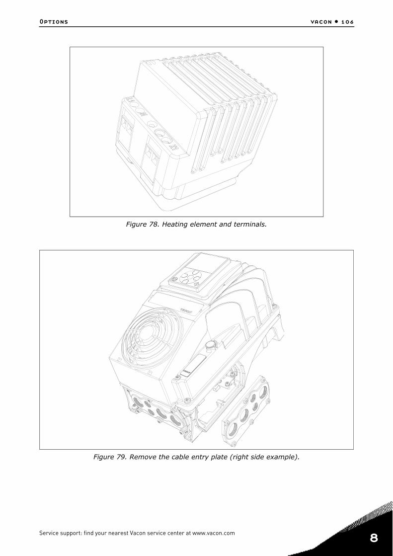
Options vacon • 106
Figure 78. Heating element and terminals.
Figure 79. Remove the cable entry plate (right side example).
Service support: find your nearest Vacon service center at www.vacon.com 8

8
vacon • 107 Options
Figure 80. Remove the powerhead from the terminal box.
Figure 81. Connect the supply voltage (black cable) and the output relay (red cable) to the op-tional heater through the bottom cable entry plate. Color of the cables is only as example.
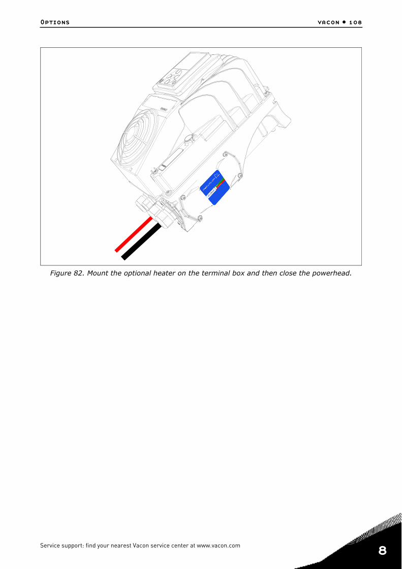
Options vacon • 108
Figure 82. Mount the optional heater on the terminal box and then close the powerhead.
Service support: find your nearest Vacon service center at www.vacon.com 8

8
vacon • 109 Options
8.4 Option boardsVACON® 100 X drive family embodies a wide selection of expander boards with which the available I/O of VACON® 100 X frequency converter can be increased and its versatility improved.
There are two board slots (labelled D and E) on the VACON® 100 X control board. To locate the slot, see chapter 5. Usually, when the AC drive is delivered from the factory, the control unit doesn’t in-clude any option board in the board slots.
The following option boards are supported:
See the Option boards User’s Manual to use and install the option boards.
Code Description Note
OPTB1 Option board with six bidirec-tional terminals.
With jumper blocks it’s possible to use each terminal as digital input or
as digital output.
OPTB2I/O expander board with a
thermistor input and two relay outputs.
OPTB4
I/O expander board with one galvanically isolated analogue
input and twogalvanically isolated analogue
outputs (standard signals 0(4)…20mA).
OPTB5 I/O expander board with three relay outputs
OPTB9I/O expander board with five
42…240 VAC digital inputs and one relay output.
OPTBFI/O expander board with ana-
logue output, digital output and relay output.
On the OPTBF board, there is one jumper block for selecting the ana-
logue output mode (mA/V).
OPTBHTemperature measurement board with three individual
channels.
Supported sensors: PT100, PT1000, NI1000, KTY84-130, KTY84-150,
KTY84-131
OPTBK AS-interface option board
OPTC4 Lonworks option board Pluggable connector with screw ter-minals
OPTE3 Profibus DP option board Pluggable connector with screw ter-minals
OPTE5 Profibus DP option board 9-pin Sub-D terminal
OPTE6 CANopen option board
OPTE7 DeviceNet option board
Table 40. Option boards supported in VACON® 100 X.

Options vacon • 110
8.5 Flange adapterVACON® 100 X is an IP66/Type 4X outdoor drive, designed to be installed as close as possible to the motor, minimizing the use of electrical rooms, integrating the drive as part of the machine, without the use of cabinets.
Vacon 100X drives are products than can be mounted directly onto the motor, machine or wherever the most efficient location for the drive is. This solution allows the machine designer, to use the available space in and around the machine, optimally. A decentralised solution provides a more flexible solution as an OEM manufacturer can deliver its machine in one piece, and there is no need to install the drives in a separate location. See the MM4 flange adapter in Figure 83.
Figure 83. Flange adapter for MM4.
These flange adapters can be used, for example, with the following motor types:
• B3 - Foot mounting• B34 - Foot - B14 face mounting• B35 - Foot - B5 flange mounting
Compared to a traditional solution, with the AC drives located in an electrical room, a decentralised solution offers significant savings potential in cabling and installation costs. By locating the drive near the machine or onto the motor, the length of the motor cable will be minimized.
ENC-QMMF-MM04 flange adapter can be used with 5 different motor sizes while both ENC-QMMF-MM05 and ENC-QMMF-MM06 flange adapters can be connected only to 3 different motor sizes. See Table 41 for further details.
Service support: find your nearest Vacon service center at www.vacon.com 8
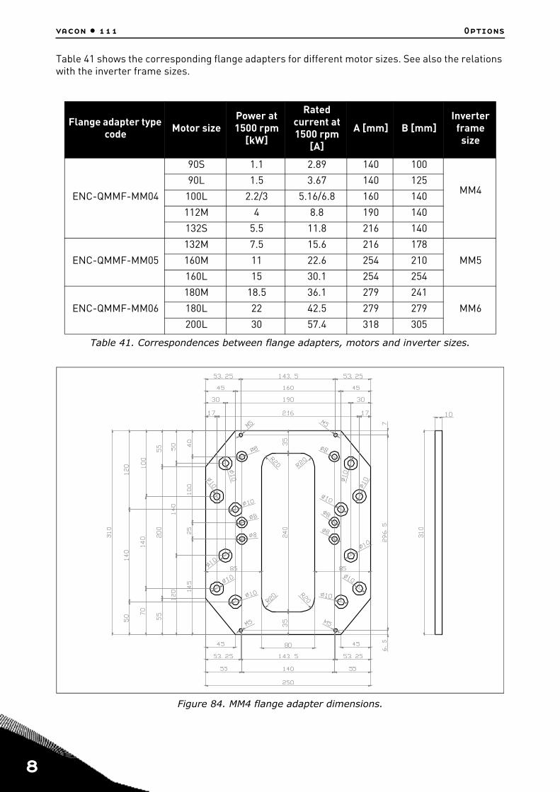
8
vacon • 111 Options
Table 41 shows the corresponding flange adapters for different motor sizes. See also the relations with the inverter frame sizes.
Figure 84. MM4 flange adapter dimensions.
Flange adapter type code Motor size
Power at 1500 rpm
[kW]
Rated current at 1500 rpm
[A]
A [mm] B [mm]Inverter
frame size
ENC-QMMF-MM04
90S 1.1 2.89 140 100
MM490L 1.5 3.67 140 125
100L 2.2/3 5.16/6.8 160 140
112M 4 8.8 190 140
132S 5.5 11.8 216 140
ENC-QMMF-MM05
132M 7.5 15.6 216 178
MM5160M 11 22.6 254 210
160L 15 30.1 254 254
ENC-QMMF-MM06
180M 18.5 36.1 279 241
MM6180L 22 42.5 279 279
200L 30 57.4 318 305
Table 41. Correspondences between flange adapters, motors and inverter sizes.

Options vacon • 112
Figure 85. MM5 flange adapter dimensions.
Figure 86. MM6 flange adapter dimensions.
Service support: find your nearest Vacon service center at www.vacon.com 8

8
vacon • 113 Options
8.5.1 Mounting instructions: MM4 Example
Figure 87. Flange adapter for MM4.
Figure 88. Mount the flange adapter on the motor.

Options vacon • 114
Figure 89. Mount the drive on the flange adapter using 4 screws.
Figure 90. Drive mounted onto the motor.
Service support: find your nearest Vacon service center at www.vacon.com 8

8
vacon • 115 Options

Safe Torque Off vacon • 116
9. SAFE TORQUE OFF This chapter describes the Safe Torque Off (STO) function which is a functional safety feature pres-ent into VACON® 100 X drive products as standard.
9.1 General descriptionThe STO function brings the motor in no-torque-state as defined by 4.2.2.2 of the IEC 61800-5-2:“Power that can cause rotation (or motion in the case of a linear motor) is not applied to themotor. The Power Drive System (Safety Related) will not provide energy to the motor which cangenerate torque (or force in the case of a linear motor).”
Therefore, the STO function is suitable for applications that rely on the immediate removal of powerto the actuator, resulting in an uncontrolled coast to stop (activated by an STO demand). Additionalprotective measures need to be applied when an application requires a different stop method.
9.2 WarningsDesigning of safety-related systems requires specialist knowledge and skills. Onlyqualified people are permitted to install and set up the STO function. The use of STOdoes not itself ensure safety. An overall risk evaluation is required for ensuring thatthe commissioned system is safe. Safety devices must be correctly incorporated intothe entire system which must be designed in compliance with all relevant standardswithin the field of industry.The information in this manual provides guidance on the use of the STO function. Thisinformation is in compliance with accepted practice and regulations at the time ofwriting. However, the end product/system designer is responsible for ensuring thatthe end-system is safe and in compliance with relevant regulations.When a permanent magnet motor is used and in case of a multiple IGBT power semi-conductor failure, when the STO option energizes the drive outputs to the off state,the drive system may still provide an alignment torque which maximally rotates themotor shaft by 180°/p (where p is the number of poles of the motor) before the torqueproduction ceases.Electronic means and contactors are not adequate for protection against electricshock. The Safe Torque Off function does not disconnect the voltage or the mainsfrom the drive. Therefore hazardous voltages may still be present on the motor. Ifelectrical or maintenance work has to be carried out on electrical parts of the driveor the motor, the drive has to be completely isolated from the main supply, e.g. usingan external supply disconnecting switch (see EN60204-1).This safety function corresponds to an uncontrolled stop in accordance with stop cat-egory 0 of IEC 60204-1. The STO function does not comply with Emergency SwitchingOff according to IEC 60204-1 (no galvanic insulation from the Mains in case the motoris stopped).The STO function is not a prevention of unexpected start-up. To fulfil those require-ments, additional external components are required according to appropriate stan-dards and application requirements.In circumstances where external influences (e.g. falling of suspended loads) arepresent additional measures (e.g. mechanical brakes) may be necessary to preventany hazard.STO shall not be used as a control for starting or stopping the drive.
Service support: find your nearest Vacon service center at www.vacon.com 9

9
vacon • 117 Safe Torque Off
9.3 StandardsThe STO function has been designed for use in accordance with the following standards:
The STO function has to be applied correctly to achieve the desired level of operational safety. Fourdifferent levels are allowed, depending on the use of the STO signals (see the following table).
Table 43. Four different STO levels. (*) see 9.5.1.
The same values are calculated for SIL and SIL CL. According to EN 60204-1, the emergency stop category is 0.
The SIL value for the safety related system, operating in high demand/continuous mode, is related to the probability of dangerous failure per hour (PFH), reported in the following table.
Standards
IEC 61508, Parts 1-7
EN 61800-5-2
EN 62061
ISO 13849-1
EN 954-1
IEC 60204-1
Table 42. Safety Standards.
STO inputs STO feedback Cat. PL SIL
Both dynamically used(*) Used 4 e 3
Both statically used Used 3 e 3
Connected in parallel Used 2 d 2
Connected in parallel Not used 1 c 1
STO inputs STO feedback PFH PFDav MTTFd(years) DCavg
Both dynamically used(*) Used 1.2 E-09 1/h 1.0 E-04 >4274 y HIGH
Both statically used Used 1.2 E-09 1/h 1.1 E-04 >4274 y MEDIUM
Connected in parallel Used 1.2 E-09 1/h 1.1 E-04 >4274 y MEDIUM
Connected in parallel Not used 1.5 E-09 1/h 1.3 E-04 >4274 y NONE
Table 44. SIL values. (*) see 9.5.1.
The STO inputs must always be supplied by a safety device.The power supply of the safety device may be external or taken from the drive (aslong as this is compliant with the rating specified for terminal 6).
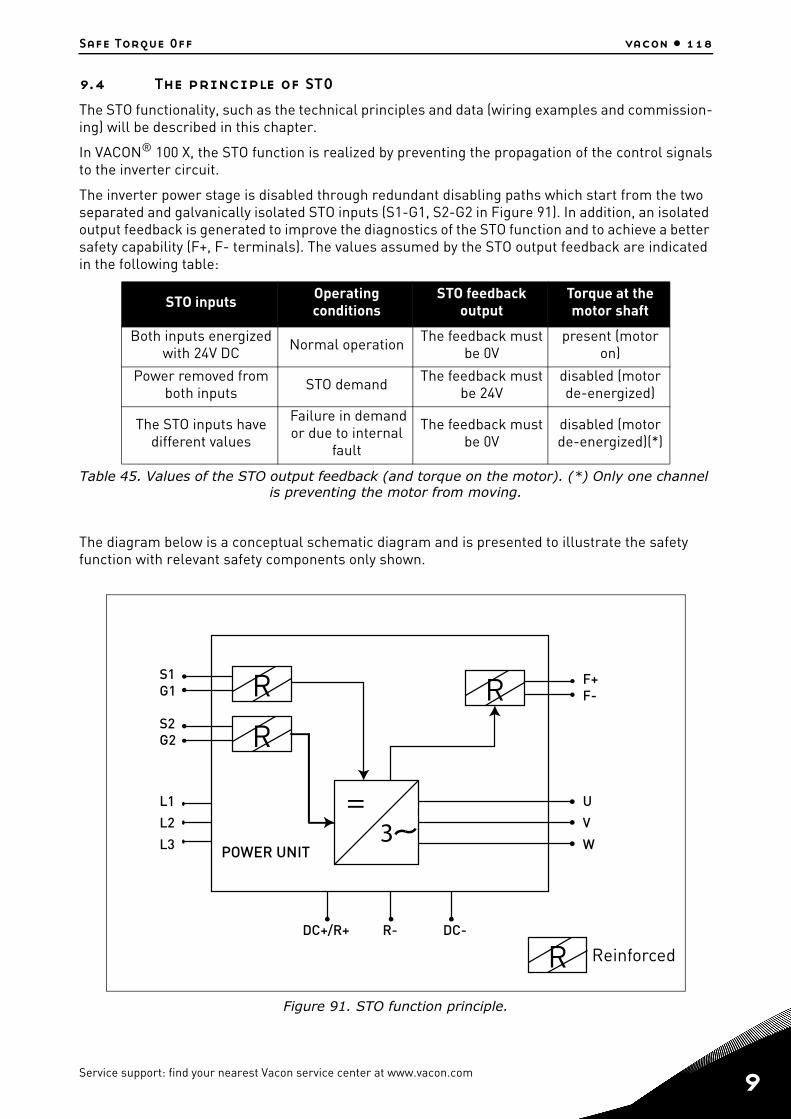
Safe Torque Off vacon • 118
9.4 The principle of STO The STO functionality, such as the technical principles and data (wiring examples and commission-ing) will be described in this chapter.
In VACON® 100 X, the STO function is realized by preventing the propagation of the control signalsto the inverter circuit.
The inverter power stage is disabled through redundant disabling paths which start from the two separated and galvanically isolated STO inputs (S1-G1, S2-G2 in Figure 91). In addition, an isolated output feedback is generated to improve the diagnostics of the STO function and to achieve a better safety capability (F+, F- terminals). The values assumed by the STO output feedback are indicated in the following table:
The diagram below is a conceptual schematic diagram and is presented to illustrate the safety function with relevant safety components only shown.
Figure 91. STO function principle.
STO inputs Operating conditions
STO feedback output
Torque at the motor shaft
Both inputs energized with 24V DC Normal operation The feedback must
be 0Vpresent (motor
on)
Power removed from both inputs STO demand The feedback must
be 24Vdisabled (motor de-energized)
The STO inputs have different values
Failure in demand or due to internal
fault
The feedback must be 0V
disabled (motor de-energized)(*)
Table 45. Values of the STO output feedback (and torque on the motor). (*) Only one channel is preventing the motor from moving.
R Reinforced
R
R R
=3
S1G1
S2G2
L1
L2
L3
F+F-
U
V
W
DC+/R+ R-
POWER UNIT
DC-
Service support: find your nearest Vacon service center at www.vacon.com 9

9
vacon • 119 Safe Torque Off
9.4.1 Technical detailsThe STO inputs are digital inputs intended for a nominal 24V d.c. input, positive logic (e.g. enabledwhen high).
The reaction time of the STO function is the amount of time which passes from the moment in which the STO is activated until the system is in the Safe State. For VACON® 100 X, the reaction time is 20 ms minimum.
Technical information: Technical values
Absolute maximum voltage range 24V ±20%
Typical input current at 24V 10...15 mA
Logic threshold according to IEC 61131-215V....30V = “1”0V....15V = “0”
Response time at nominal voltage:
Reaction time <20ms
Table 46. Electrical data.
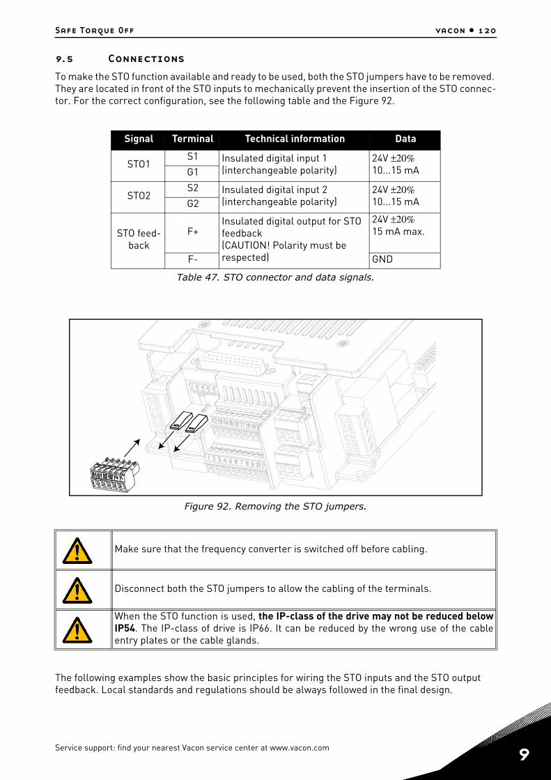
Safe Torque Off vacon • 120
9.5 ConnectionsTo make the STO function available and ready to be used, both the STO jumpers have to be removed. They are located in front of the STO inputs to mechanically prevent the insertion of the STO connec-tor. For the correct configuration, see the following table and the Figure 92.
Figure 92. Removing the STO jumpers.
The following examples show the basic principles for wiring the STO inputs and the STO output feedback. Local standards and regulations should be always followed in the final design.
Signal Terminal Technical information Data
STO1S1 Insulated digital input 1
(interchangeable polarity)24V ±20%10...15 mAG1
STO2S2 Insulated digital input 2
(interchangeable polarity)24V ±20%10...15 mAG2
STO feed-back
F+Insulated digital output for STO feedback(CAUTION! Polarity must be respected)
24V ±20%15 mA max.
F- GND
Table 47. STO connector and data signals.
Make sure that the frequency converter is switched off before cabling.
Disconnect both the STO jumpers to allow the cabling of the terminals.
When the STO function is used, the IP-class of the drive may not be reduced belowIP54. The IP-class of drive is IP66. It can be reduced by the wrong use of the cableentry plates or the cable glands.
Service support: find your nearest Vacon service center at www.vacon.com 9

9
vacon • 121 Safe Torque Off
9.5.1 Safety Capability Cat. 4 / PL e / SIL 3For this safety capability, an external safety device must be installed. This must be used to dynam-ically activate the STO inputs and to monitor the STO output feedback.
The STO inputs are dynamically used when they do not commute together (static use), but according to the following picture (where the inputs are released with delay in turn). The dynamic use of the STO inputs allows detecting faults that may otherwise accumulate.
Figure 93.
An emergency push button connected to the STO inputs does not assure the samequality, because no fault detection is performed at a sufficient frequency (once a dayis recommended).The external safety device, which forces the STO inputs and evaluates the STO outputfeedback, has to be a safe device and it has to fulfil the requirements of the specificapplication.
A simple switch cannot be used in this case!

Safe Torque Off vacon • 122
The picture below shows an example of connection for the STO function. The external device has to be connected with 6 wires to the drive.
Figure 94. STO example with automatic monitoring of the feedback and both STO inputs used.
The external device has to monitor the STO function in accordance with theTable 45. The device hasto periodically de-energize the STO inputs and it has to verify that the STO output feedback assumesthe expected value.
Any difference between the expected and the real value has to be considered as a failure and has todrive the system into a Safe State. In case of failure, check the wiring. If the fault recognized by theexternal safety device persists, the drive will have to be replaced/repaired.
R
R
R R
=3
S1G1
S2G2
L1
L2
L3
F+F-
U
V
W
DC+/R+ R- DC-
Reinforced
POWER UNIT
EXTERNAL DEVICE
Service support: find your nearest Vacon service center at www.vacon.com 9
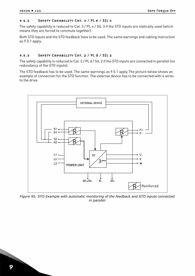
9
vacon • 123 Safe Torque Off
9.5.2 Safety Capability Cat. 3 / PL e / SIL 3The safety capability is reduced to Cat. 3 / PL e / SIL 3 if the STO inputs are statically used (which means they are forced to commute together).
Both STO inputs and the STO feedback have to be used. The same warnings and cabling instruction as 9.5.1 apply.
9.5.3 Safety Capability Cat. 2 / PL d / SIL 2The safety capability is reduced to Cat. 2 / PL d / SIL 2 if the STO inputs are connected in parallel (no redundancy of the STO inputs).
The STO feedback has to be used. The same warnings as 9.5.1 apply.The picture below shows an example of connection for the STO function. The external device has to be connected with 4 wires to the drive.
Figure 95. STO Example with automatic monitoring of the feedback and STO inputs connected in parallel.
R
R
R R
=3
S1G1
S2G2
L1
L2
L3
F+F-
U
V
W
DC+/R+ R- DC-
Reinforced
POWER UNIT
EXTERNAL DEVICE

Safe Torque Off vacon • 124
9.5.4 Safety Capability Cat. 1 / PL c / SIL 1Without any automatic monitoring of STO output feedback, the safety capability is reduced to Cat. 1 / PL c / SIL 1. The STO inputs (which can be connected in parallel) must be supplied by a safety push button or a safety relay.
The picture below shows an example of connection for the STO function. A switch (a safety push but-ton or a safety relay) may be connected with 2 wires to the drive.
When the contacts of the switch are opened, the STO is demanded, the drive indicates F30 (="SafeTorque Off") and the motor stops by coasting.
Figure 96. STO example without automatic monitoring of the feedback and STO inputs connect-ed in parallel.
The choice of using the STO inputs (without the automatic monitoring of the outputfeedback) does not allow other safety capabilities to be achieved.
The standards for functional safety require that functional proof tests are performedon the equipment at user-defined intervals. Therefore, this safety capability can beachieved, as long as the STO function is manually monitored at the frequency deter-mined by the specific application (once a month can be acceptable).
This safety capability can be achieved by connecting in parallel the STO inputs exter-nally and by ignoring the use of the STO output feedback.
R
R
R R
=3
S1G1
S2G2
L1
L2
L3
F+F-
U
V
W
DC+/R+ R- DC-
SWITCH
Reinforced
POWER UNIT
Service support: find your nearest Vacon service center at www.vacon.com 9

9
vacon • 125 Safe Torque Off
9.6 Commissioning
9.6.1 General wiring instructions
The wiring should be done according to the general wiring instructions for the specific product. Ashielded cable is required. In addition, the voltage drop from the supply point to the load shall notexceed 5% [EN 60204-1 part 12.5].
The following table indicates examples of cables to be used.
9.6.2 Checklist for commissioningFollow the checklist shown in the table below for the steps required to use the STO function.
Protect the STO cabling with a shielding or an enclosure to exclude external damage.
Wires ferrules are highly recommended for all STO signals (inputs and feedback).
STO feedback Cable size
STO feedback automatically monitored by an external safety
device3 x (2 + 1) x 0,5 mm2(*)
STO feedback ignored, simply safety device (switch) used 2 x (2 + 1) x 0,5 mm2
Table 48. Cable types required to meet the standards. (*) Additional wires are needed for restarting the drive after each STO demand.
Carry out a risk assessment of the system to ensure that the use of the STO function issafe and according to the local regulations
Include in the assessment an examination of whether the use of external devices, suchas a mechanical brake, are required.
Check if the switch (if used) has been chosen according to the required safety perfor-mance target (SIL/PL/Category) set during the risk evaluation
Check if the external device for automatic monitoring of the STO output feedback (ifused) has been chosen in accordance with the specific application
Check if the reset function with the STO function (if used) is edge sensitive.
The shaft of a permanent magnet motor might, in an IGBT fault situation, still provideenergy before the torque production ceases. This may result in a jerk of max. 180° elec-trically. Ensured that the system is designed in such a way that this can be accepted.
Check if the degree of protection of the enclosure is at least IP54. See paragraph 9.5.
Check if the recommendations on EMC for cables have been followed.
Check if the system has been designed in such a way that enabling of the drive through STO inputs will not lead to an unexpected start of the drive.
Check if only approved units and parts have been used.
Set up a routine to ensure that the functionality of the STO function is being checked atregular intervals.
Table 49. Checklist for commissioning of STO.

Safe Torque Off vacon • 126
9.7 Parameters and fault tracingThere are no parameters for the STO function itself.
To re-enable motor operation, after the STO state, it is necessary to perform the following steps:
• Release the switch or the external device (“F30” is displayed even after this has beenreleased).
• Reset the fault (through a digital input or from the keypad).• It is possible that a new start command is required for the restart (depending on the applica-
tion and your parameter settings).
9.8 Maintenance and diagnostics
The STO function or the STO input/output terminals do not need any maintenance.
The following table shows faults that may be generated by the software that monitors the hardware related to the STO safety function. If you detect any failure in safety functions, including STO, contact your local VACON® supplier.
Before testing the STO function, make sure that the checklist (Table 49) is inspectedand completed.
When STO function activates, the drive always generates a fault (“F30”) and themotor stops by coasting.
In the application the STO state can be indicated using a digital output.
If any service or repair is to be conducted on the drive installed, please inspect thechecklist given in Table 49
During maintenance breaks, or in case of service/repair, ALWAYS make sure that theSTO function is available and fully functional by testing it.
Fault Code Fault Cause Correction
30 Safe Torque Off
STO inputs in a differ-ent state or both de-
energizedCheck cabling
Table 50. Fault related to the STO function.
Service support: find your nearest Vacon service center at www.vacon.com 9


Document ID:
Order code:
Rev.H
Manual authoring:[email protected]
Vacon Plc.Runsorintie 765380 VaasaFinland
Subject to change without prior notice© 2015 Vacon Plc.
Find your nearest Vacon office on the Internet at:
www.vacon.com