installation & user guide - wind speed data loggers and ... · installation & user guide...
TRANSCRIPT
Installation & User
Guide
LeWL
August, 2008

Revision Sheet
Installation Manual Page i
Logic Energy Ltd. Registered in Scotland No. SC323404
Revision Sheet
Release No. Date Revision Description
Rev. 1 27-08-08 Initial Manual
Rev. 1a 30-09-08 Edited setup menu
Rev. 1c 28-10-08 Added wind direction setup
Rev. 1d 04-12-08 Edited setup menu
Rev. 1e 01-03-09 Wind rose changed to degrees
Rev. 1f 22-04-09 Setup via SD card

Revision Sheet
Installation Manual Page ii
Logic Energy Ltd. Registered in Scotland No. SC323404
Important Notice
You must read and agree to the License Agreement and conditions of use before you commence using the
product. If you do not agree, you must return the whole package to the point of purchase.
Disclaimers
Logic Energy Ltd. assumes no liability for damages consequent to the user of this product. This
document is being supplied to you solely for information purposes and may not be reproduced or
distributed to any other person or parties in whole or in part for any purpose. The information provided
in this manual is intended for instructional purposes only. This document is subject to change without
notice and does not represent a commitment on the part of the manufacturer. Every effort has been made
to make this guide as complete and as accurate as possible, but no warranty or fitness is implied. The
author and the publisher shall have neither responsibility nor liability to any person or entity with respect
to loss or damages arising from the use of information contained in this guide. Logic Energy Ltd accepts
no responsibility or liability for errors, omissions, or misleading information that may be contained in
this manual.
Copyright
This manual is copyrighted by Logic Energy Ltd. All rights are reserved. This document may not, in
whole or in part, be copied, photocopied, reproduced, translated, or pre-produced on any electronic
medium or machine-readable form without prior consent. © 2007 – 2008. Logic Energy Ltd. All rights
reserved.
Contact Details
Logic Energy Ltd.
1 Ainslie Road
Hillington Park
Glasgow, G52 4RU
Scotland, UK
Web : www.windlogger.co.uk
Email : [email protected]
Installation Manual Page iii
© Logic Energy Ltd.
INSTALLATION MANUAL
TABLE OF CONTENTS
Page #
1.0 GENERAL INFORMATION ......................................................................................................1-1
1.1 Safety .......................................................................................................................................1-1
1.2 Disclaimer................................................................................................................................1-2
2.0 INTRODUCTION........................................................................................................................2-1
2.1 System Operations..................................................................................................................2-1
2.2 Acronyms and Abbreviations................................................................................................2-1
3.0 INSTALLATION .........................................................................................................................3-1
3.1 Hardware Installation............................................................................................................3-1 3.1.1 Sensors................................................................................................................................................3-2
3.1.1.1 Anemometers and wind vanes ...................................................................................................3-2 3.1.2 Power ..................................................................................................................................................3-3 3.1.3 Operation ............................................................................................................................................3-3
3.2 Extracting data from the memory card ...............................................................................3-4 3.2.1 LeWL Setup menu ..............................................................................................................................3-5
3.2.1.1 Select data logging interval .......................................................................................................3-7 3.2.1.2 Change anemometer factor ........................................................................................................3-7 3.2.1.3 Adjust the time and date ............................................................................................................3-8 3.2.1.4 Select number of anemometers..................................................................................................3-8 3.2.1.5 Calibrate Wind direction ...........................................................................................................3-9
3.2.2 LeWL Setup via menu.txt file on the SD card ..................................................................................3-10 3.2.3 Receive data on the serial port ..........................................................................................................3-12
3.3 Physical Dimensions.............................................................................................................3-13
3.4 Product Technical Specification .........................................................................................3-13
4.0 TROUBLESHOOTING...............................................................................................................4-1
5.0 WARRANTY ................................................................................................................................5-1

1.0 General Information
Installation Manual
© Logic Energy Ltd.
1.0 GENERAL INFORMATION

1.0 General Information
Installation Manual Page 1-1
© Logic Energy Ltd.
1.0 GENERAL INFORMATION
1.1 Safety
Contact with AC electrical mains can cause a severe electric shock and could be lethal.
• Never remove the cover from LeWL if you are not sure what you are doing.
• Follow the set-up instructions in this manual to make sure all electrical connections are made
properly.
• Do not connect any equipment to the battery supply until you have properly connected all the
other leads.
• Never push anything into holes, slots or other openings in the LeWL unless specifically detailed
in this document.
• All Logic Energy products have been designed with ease of use in mind.
Caution:
• Do not use or store LeWL devices without its cover lid and/or open gland in hot, cold, damp or
dusty places as this could affect the unit’s performance and may prove to be a fire hazard.
• Do not put anything on the LeWL device that might spill (e.g. drinks, plants, etc).
• Do not place the unit on top of a unit which emits heat.
• Never leave the box’s cover removed while operation, unless indicated by this manual.
• A service should be carried out only by an authorised Logic Energy service centre or Logic
Energy authorised engineer.

1.0 General Information
Installation Manual Page 1-2
© Logic Energy Ltd.
1.2 Disclaimer
In no circumstances will Logic Energy be liable for any direct, indirect, consequential or incidental
damage, including loss of profits, business interruption and loss of data arising out of the use or the
inability to use the software or hardware however caused, save to the extent that such liability is not
capable of exclusion at law. These limitations of liability apply even if Logic Energy or a third party
reseller have been advised of the possibility of such damage occurring.

2.0 Introduction
Installation Manual
© Logic Energy Ltd.
2.0 INTRODUCTION
2.0 System Operations Overview
Installation Manual Page 2-1
© Logic Energy Ltd.
2.0 INTRODUCTION
2.1 System Operations
LeWL is an automatic stand alone data logger that provides flexible and powerful data logging
capabilities, specifically designed for the Energy Industry. LeWL is able to monitor 2 digital inputs, 1
analogue inputs and a built-in temperature sensor. LeWL works together with different anemometers and
wind vanes to log in real time wind speed and direction onto a flash memory card.
Each data record has a date and/or time stamp when stored on the memory card. Files (.CSV) are
archived either by month or day depending on the pre-set logging speed.
All data including settings are stored onto a SD or MMC card (up to 2GByte capacity). This simplifies
the collection of data by just removing the memory card from the LeWL wind logger and inserting it onto
a PC card reader. All stored files can be accessed with a standard text editor or any spreadsheet program
like MS EXcel or OpenOffice.
The LeWL wind logger is powered by two C type batteries which provide more than a year battery when
logging on 1 minute intervals or higher.
2.2 Acronyms and Abbreviations
CSV: A data format originally known as comma-separated values (CSV).
FAT16: Older version of the FAT file system, based on 16-bit integers.
FAT32: File Allocation Table, 32 bits; a modified form of the FAT16 file system.
RTC: Real Time Clock.
RS232: Standardised connection system for connecting a device to the serial port of a computer or
terminal.
IP65: Ingress Protection sealing 6 = Totally sealed against dust and water; 5 = Protected against low
pressure water jets from any direction.
Hertz: Frequency in cycles per second, 1 hertz equals 1 cycle per second.
3.0 Installation
Installation Manual
© Logic Energy Ltd.
3.0 INSTALLATION

3.0 Installation
Installation Manual Page 3-1
© Logic Energy Ltd.
3.0 INSTALLATION
3.1 Hardware Installation
LeWL can be wall mounted using the four holes provided on each corner of the box. These are
underneath the transparent lid:
Fig. 1
- Always make sure the logger is mounted with its gland facing down to avoid any possible water leaks -
The connectors are labelled and numbered as Input, Outputs, Power and Analogue on the circuit board.
See Fig. 2 for connector’s layout:
Fig.2
From left to right:
G: Common ground
A2: Input sensor 2
G: Common ground
A1: Input sensor 1 (lowest power consume)
G: Common ground
D: Input wind direction sensor
D+: Wind direction sensor power
V+: Lower DC positive power (red)
G: Common ground (black)

3.0 Installation
Installation Manual Page 3-2
© Logic Energy Ltd.
3.1.1 Sensors
LeWL has 2 digital inputs for anemometers and 1 analogue input for the wind direction sensor. For a set
of compatible wind sensors, please visit www.windlogger.co.uk
3.1.1.1 Anemometers and wind vanes
The anemometers are connected to the LeWL by using one of the common grounds and an “A” input. A1
input is the default when using just one anemone as it uses less power. Do not use A2 if you are gong to
use one anemometer only.
Fig. 3
For setting up the wind direction vane, please make sure to read section 3.2.1.5
3.0 Installation
Installation Manual Page 3-3
© Logic Energy Ltd.
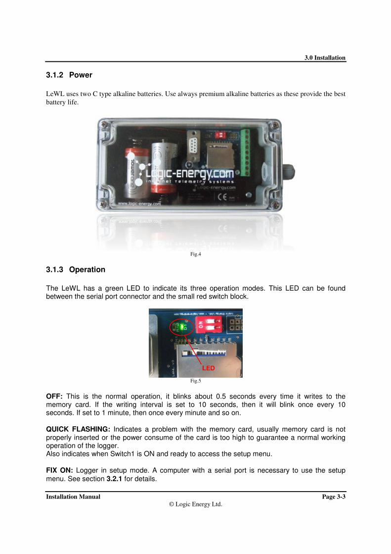
3.1.2 Power
LeWL uses two C type alkaline batteries. Use always premium alkaline batteries as these provide the best
battery life.
Fig.4
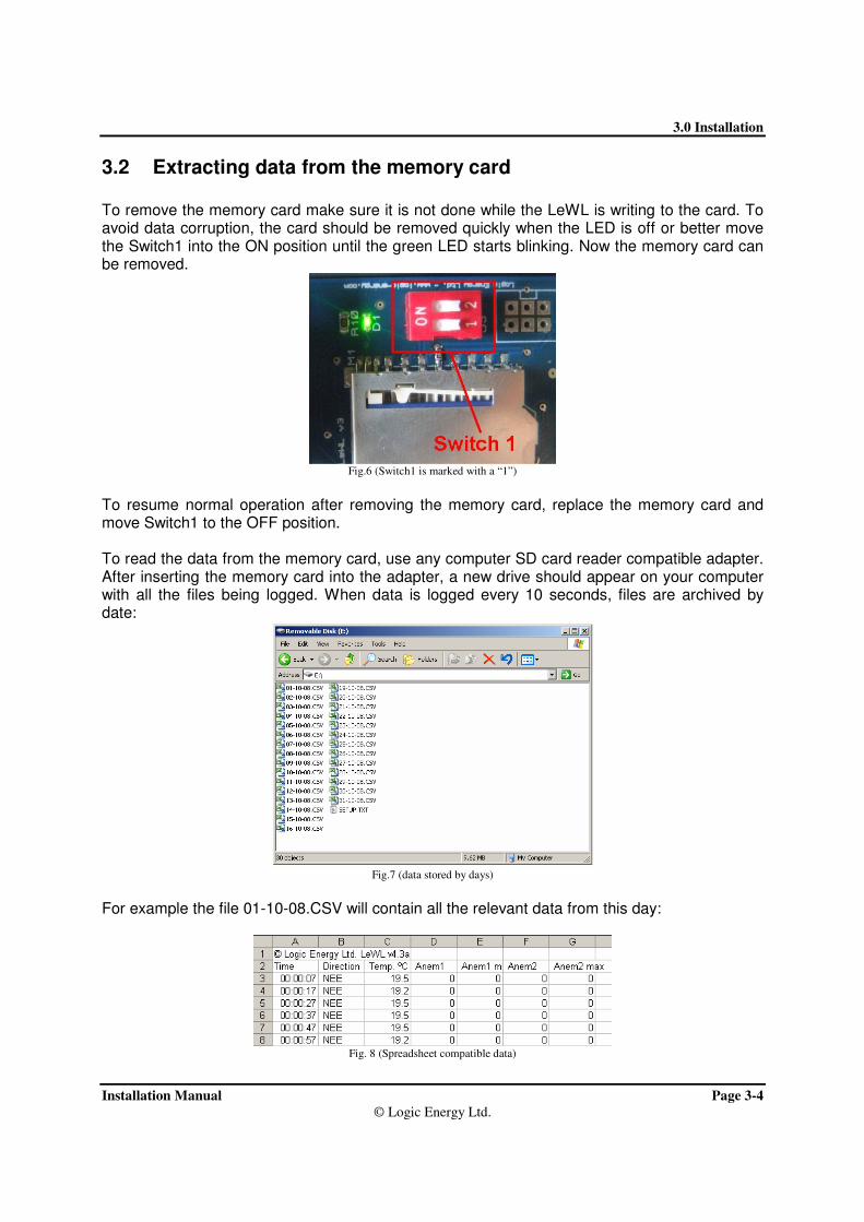
3.1.3 Operation
The LeWL has a green LED to indicate its three operation modes. This LED can be found between the serial port connector and the small red switch block.
Fig.5
OFF: This is the normal operation, it blinks about 0.5 seconds every time it writes to the memory card. If the writing interval is set to 10 seconds, then it will blink once every 10 seconds. If set to 1 minute, then once every minute and so on. QUICK FLASHING: Indicates a problem with the memory card, usually memory card is not properly inserted or the power consume of the card is too high to guarantee a normal working operation of the logger. Also indicates when Switch1 is ON and ready to access the setup menu. FIX ON: Logger in setup mode. A computer with a serial port is necessary to use the setup menu. See section 3.2.1 for details.
3.0 Installation
Installation Manual Page 3-4
© Logic Energy Ltd.
3.2 Extracting data from the memory card
To remove the memory card make sure it is not done while the LeWL is writing to the card. To avoid data corruption, the card should be removed quickly when the LED is off or better move the Switch1 into the ON position until the green LED starts blinking. Now the memory card can be removed.
Fig.6 (Switch1 is marked with a “1”)
To resume normal operation after removing the memory card, replace the memory card and move Switch1 to the OFF position. To read the data from the memory card, use any computer SD card reader compatible adapter. After inserting the memory card into the adapter, a new drive should appear on your computer with all the files being logged. When data is logged every 10 seconds, files are archived by date:
Fig.7 (data stored by days)
For example the file 01-10-08.CSV will contain all the relevant data from this day:
Fig. 8 (Spreadsheet compatible data)

3.0 Installation
Installation Manual Page 3-5
© Logic Energy Ltd.
By minute or 10 minutes, files are archived by months.
Fig. 9 (data stored by months)
The SETUP.TXT file contains details of the configuration done on the LeWL logger: date, time of the day a new configuration was done, recording interval and the conversion factors of the anemometers:
16-10-08, 17:16:51, Avg_time=10, Sensor1=1.05999994, Sensor2=1.05999994
19-10-08, 17:18:01, Avg_time=10, Sensor1=1.05999994, Sensor2=1.05999994
08-11-08, 21:43:04, Avg_time=10, Sensor1=1.05999994, Sensor2=1.05999994
09-11-08, 16:03:53, Avg_time=10, Sensor1=1.05999994, Sensor2=1.05999994
3.2.1 LeWL Setup menu
LeWL has a built-in menu system to allow for different configuration options. All the configured values but date and time are stored on “non volatile” memory, therefore it is not necessary to configure the LeWL wind logger everything it needs to be used. Old parameters will keep to be using unless re-configured again. To enter the menu mode connect a serial cable to the LeWL with the following settings on HyperTerminal (Windows OS) or similar terminal program:
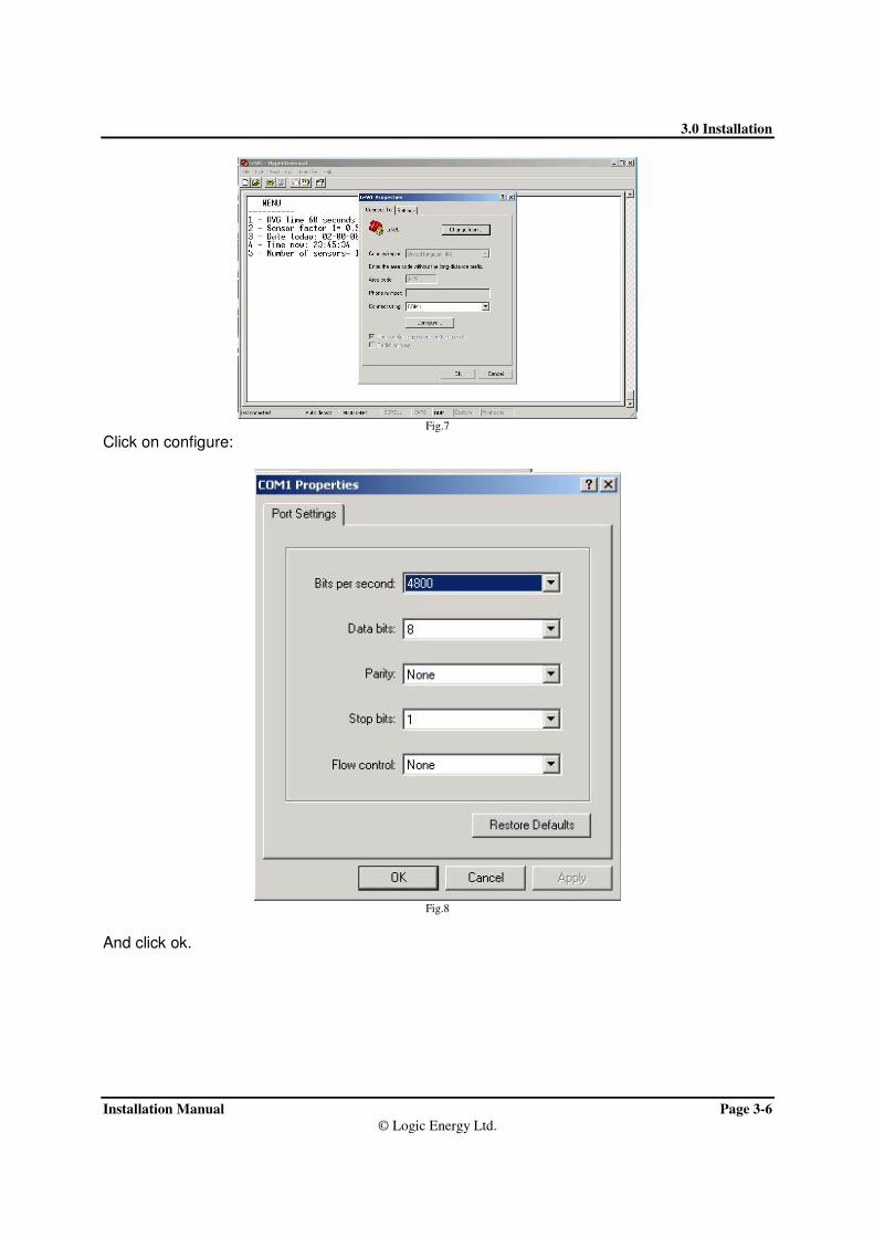
1. The COM port you are using 2. 4800 bits per second 3. Data bits 8 4. Parity None 5. Stop bits 1 6. Flow control None
3.0 Installation
Installation Manual Page 3-6
© Logic Energy Ltd.
Fig.7
Click on configure:
Fig.8
And click ok.

3.0 Installation
Installation Manual Page 3-7
© Logic Energy Ltd.
When this is done, place Switch1 into ON position, the LED will start blinking. Press capital “M” on your computer’s keyboard. You should see a menu like this:
MENU - 4.3.2a ------------ 1 - AVG Time 60 seconds 2 - Anemometer setup 3 - Date today: 12:09:08 4 - Time now: 13:49:25 5 - Number of anemometers = 1 6 - Wind direction calibration Select option and press Enter (Switch off menu switch and press Enter to start logging)
3.2.1.1 Select data logging interval
Select 1 and enter to change the averaging periods to write to the memory card:
1 - 10 secs 2 - 1 min 3 - 10 min 4 - Back (60) ?
Pick you choice and press enter (by default it is set to 1 minute average)
3.2.1.2 Change anemometer factor
Press 2 and enter to access the variables assigned to each sensor. Select from the list the anemometer you are using:
ANEMOMETER A1 = LE-Basic Select type: ------------ Anemometer LE-Access > 1 Anemometer LE-Pro > 2 Anemometer custom > 3 Exit > 4 ?
If using a custom anemometer, select 3 and enter the conversion factor from Hertz to meters per second or any other wished unit:
Sensor 1 Hz/= (0.5) ?
Enter value and press enter. The same menu will appear for Anemometer 2 (A2).

3.0 Installation
Installation Manual Page 3-8
© Logic Energy Ltd.
3.2.1.3 Adjust the time and date
Press 3 to access the date menu:
MENU - 4.3.2a ------------ 1 - AVG Time 60 seconds 2 - Anemometer setup 3 - Date today: 12:09:08 4 - Time now: 13:49:25 5 - Number of anemometers = 1 6 - Wind direction calibration Select option and press Enter
Enter date dd/mm/yy
Enter date and press Enter. Press 4 to adjust the time:
MENU - 4.3.2a ------------ 1 - AVG Time 60 seconds 2 - Anemometer setup 3 - Date today: 12:09:08 4 - Time now: 13:49:25 5 - Number of anemometers = 1 6 - Wind direction calibration Select option and press Enter
Enter time in 24h, hh:mm:ss
Enter time and press Enter.
- Notice that if batteries are removed, date and time will be reset -
3.2.1.4 Select number of anemometers
Press 5 and enter to select the number of anemometers. The option is 1 or 2.
MENU - 4.3.2a ------------ 1 - AVG Time 60 seconds 2 - Anemometer setup 3 - Date today: 12:09:08 4 - Time now: 13:49:25 5 - Number of anemometers = 1 6 - Wind direction calibration Select option and press Enter
Enter Number of Anemometers (1/2)
By default the number of anemometers is set to 1
• Note: 2 anemometers have considerable more power consumption than one.

3.0 Installation
Installation Manual Page 3-9
© Logic Energy Ltd.
3.2.1.5 Calibrate Wind direction
This is a new feature added to the LeWL version 4.3.a onwards. This option facilitates the orientation of the wind vane towards North. This is useful very useful to install the wind vane without necessarily pointing towards North. To do the wind vane calibration, follow the next steps:
MENU - 4.3.2a ------------ 1 - AVG Time 60 seconds 2 - Anemometer setup 3 - Date today: 12:09:08 4 - Time now: 13:49:25 5 - Number of anemometers = 1 6 - Wind direction calibration Select option and press Enter
Press 6 and Enter to enter wind vane calibration mode: Wind direction offset = nnn (number) Point Wind Vane to North and press Enter when ready
nnn => is an offset number that will have a different value depending on where the wind vane is pointing. After pressing Enter, a new value will be displayed: The new offset value is: nnn (number) Store value (Y/N)
If it was intended to change the offset value, press Yes (Y/y), otherwise No (N/n) to use the old value. Depending on the election, the new value will be used or rejected: Yes New value nnn stored
No Old value nnn used
After everything is ready, move Switch1 to the OFF position and press enter. Leave the serial cable connected and read Section 3.2.2, if the readings are of your satisfaction, disconnect the serial cable with care.

3.0 Installation
Installation Manual Page 3-10
© Logic Energy Ltd.
3.2.2 LeWL Setup via menu.txt file on the SD card
The LeWL wind logger can be also setup via the SD card. This is done by modifying the “menu.txt” file on the SD card supplied or download from www.windlogger.co.uk/menu.txt
Fig. 9
The file menu.txt contains all the parameters to setup the wind logger. The file SETUP.TXT contains a log of all the setup changes carried out on the LeWL wind logger. Please do not delete any of these. The LeWL wind logger will look at any changes done on the menu.txt file and only if the file has been modified with new settings, changes will be taken. Open the menu.txt file with Notepad or similar ASCII text editor and the following parameters will be displayed: Please follow the instructions on the manual carefully - use lower case always ------------------------------------------------------------------------------ You can download a default file from www.windlogger.co.uk/menu.txt ------------------------------------------------------------------ - Date: Type the date you want to setup the logger as "dd/mm/yy", no spaces - 07/04/09 - Time: Type the time you want to setup the logger as "hh:mm:ss" in 24h format, no spaces - 14:34:00 - Anemometers: Type the number of anemometer you will be using, "1" or "2" only - 1 - Average time: Type the logging interval, "10" for 10 seconds, "60" for 1 minute or "600" for 10 minutes only - 10 - Anemometer1 setup: "access" for Access Anemometer, "pro" for Pro Anemometer - pro - Anemometer1 setup: "access" for Access Anemometer, "pro" for Pro Anemometer - pro - Self North calibration: Point wind vane to north and write "yes" to re-adjust it. "no" to keep old calibration - yes
You should edit only the values marked here in yellow.

3.0 Installation
Installation Manual Page 3-11
© Logic Energy Ltd.
Anemomter1 and Anemometer2 setup: It is only possible to setup the anemometer to Access or Pro from the menu.txt file. If a custom value needs to be entered, please use the serial port interface and setup menu.
Self North calibration : When setting up the “Self North calibration” to yes, please make sure the wind vane is fixed pointing North when the new LeWL wind logger is switched on for the first time to take on the new parameters from the menu.txt file.
After the new settings have been edited, save the file on the SD card and insert it on the LeWL wind logger. The LeWL will detect these are new settings. After new settings have been changed, you should see the green LED on the LeWL do one long blink followed by two shorter blinks before going into normal operation. This indicates new settings have been setup successfully. If you want to be 100% sure the new parameters have been successfully setup, after the LeWL finishes writing to the SD card (indicated by the green LED), remove the SD card and open the SETUP.TXT file. You will find a log of all the changes done over time with the last one being the one you just did: 07-04-09, 14:34:00, Avg_time=10, Sensor1=1.006000039, Sensor2=1.006000039, WD offset=865
Date Time Logging interval Anem1 conversion factor Anem2 conversion factor Wind direction calibration

3.0 Installation
Installation Manual Page 3-12
© Logic Energy Ltd.
3.2.3 Receive data on the serial port
After everything is ready, move Switch1 to the OFF position and press enter. If you still have the serial port connected to the PC, you should see something like this: Card found: 120818 KB 16-06-08, 19:38:36, 90, 21.7, 0.7, 1.3 -> Everytime the LeWL writes to the memory card, it outputs a line to the serial port, this would happen every 10s, 1min or 10min. 16-06-08 -> Date in dd-mm-yy format 19:38:36 -> Time in 24h format 90 -> Wind direction in degrees, 90º = East. Value increasing clockwise into 16 bins 21.7 -> Temperature in ºC (Celsius) 0.7 -> Average wind speed m/s 1.3 -> Maximum wind speed in m/s during logging period
A fast blinking LED at any time means there’s a PROBLEM. If you leave the serial cable connected you can confirm that it is working by seeing a line of the data written every time it does so or the error message.
It is very important to check the data is being collected properly and the LeWL wind logger is setup properly before leaving the unit on site. To do this connect a
computer’s serial port to the LeWL as indicated in Section 3.2.1 and wait for at least the first stream of data on the serial port. Check the number of anemometer logged and the date and time is correct.

3.0 Installation
Installation Manual Page 3-13
© Logic Energy Ltd.
3.3 Physical Dimensions
Fig. 10
3.4 Product Technical Specification
Memory: SD/MMC flash card (FAT16/32)
Power: 2 x Alkaline batteries 1.5v C size
Operating Temperature: -15ºC to +50ºC
Sensor Input: 1 Analogue and 2 Digital input Channel.
Communications: RS232 @ 4800
Logging Interval: 10 second, 1 or 10 minutes, user-specified interval.
Output: CSV ASCII format data file.
By default data stored in meters per seconds [m/s]
Housing: Sealed plastic case. (IP65)
Dimensions: 160x80x55mm.
Weight: 450 gm (including batteries).

4.0 Troubleshooting
Installation Manual Page 4-1
© Logic Energy Ltd.
4.0 TROUBLESHOOTING

4.0 Troubleshooting
Installation Manual Page 4-2
© Logic Energy Ltd.
Problem: Data is not written to the memory card
Solution: This is likely to be a memory card corrupted or an excessive power being needed to power up the memory
card. Some memory cards use much more power than others. To warrantee a long battery life, LeWL limits the
current being supplied to the memory card. We recommend using the memory cards supplied by Logic Energy Ltd.
Problem: The time and date has been reset to 00
Solution: LeWL uses its battery to keep its internal clock working. If at any time the batteries are removed, LeWL
will reset its time and date to 00. Make sure to follow instructions on section 3.2.1 to setup the time and date.
Problem: LeWL’s green LED doesn’t stop blinking.
Solution: Make sure the memory card is properly inserted and Switch1 set to OFF.
.

4.0 Troubleshooting
Installation Manual Page 5-1
© Logic Energy Ltd.
5.0 WARRANTY

4.0 Troubleshooting
Logic Energy Ltd, 1 Ainslie Road, Hillington Park Page 5-2
Glasgow, G52 4RU, Scotland, UK
Tel: +44(0)141 585 6496 Fax: +44(0)141 585 6497
www.logic-energy.com e-mail: [email protected]
All products manufactured by Logic Energy Ltd., are warranted against defective materials for a period
of one year from the date of delivery to the original purchaser.
THE WARRANTY WILL NOT APPLY TO THE PRODUCT IF IT HAS BEEN DAMAGED BY
MISUSE, ALTERATION, ACCIDENT, IMPROPER HANDLING OR OPERATION, OR IF
UNAUTHORIZED REPAIRS ARE ATTEMPTED OR MADE. SOME EXAMPLES OF DAMAGES
NOT COVERED BY WARRANTY INCLUDE, BUT ARE NOT LIMITED TO, BATTERY
LEAKAGE, BENDING, OR VISIBLE CRACKING OF THE PCB, WHICH ARE PRESUMED TO BE
DAMAGES RESULTING FROM MISUSE OR ABUSE.
THIS WARRANTY DOES NOT COVER THE ACCURACY OF THE SENSORS CONNECTED TO
THE LeWL WIND LOGGER OR THE ACCURACY OF THE DATA COLLECTED BY THE LeWL
WIND LOGGER.