installation, user's, and maintenance
TRANSCRIPT
8/9/2019 Installation, User's, And Maintenance
http://slidepdf.com/reader/full/installation-users-and-maintenance 1/262
IBM System Storage DCS3700 Storage Subsystem andDCS3700 Storage Subsystem with Performance ModuleControllers
Installation, User's, and Maintenance Guide
GA32-0959-07
8/9/2019 Installation, User's, And Maintenance
http://slidepdf.com/reader/full/installation-users-and-maintenance 2/262
Note
Before using this information and the product it supports, be sure to read the general information in the “Safety” on pageix and “Notices” on page 217 sections.
This edition applies to the IBM System Storage DCS3700 Storage Subsystem and DCS3700 Storage Subsystem withPerformance Module Controllers, with controller firmware version 7.77, and to all subsequent releases andmodifications until otherwise indicated in new editions.
This edition replaces GA32-0959-06.
Printed in the U.S.A.
© Copyright IBM Corporation 2011, 2013.US Government Users Restricted Rights – Use, duplication or disclosure restricted by GSA ADP Schedule Contractwith IBM Corp.
8/9/2019 Installation, User's, And Maintenance
http://slidepdf.com/reader/full/installation-users-and-maintenance 3/262
8/9/2019 Installation, User's, And Maintenance
http://slidepdf.com/reader/full/installation-users-and-maintenance 4/262
Troubleshooting the storage subsystem . . . . 81Checking the LEDs . . . . . . . . . . . . 81
Front LEDs . . . . . . . . . . . . . 82Controller LEDs . . . . . . . . . . . . 82ESM LEDs. . . . . . . . . . . . . . 85Fan assembly LEDs . . . . . . . . . . . 86AC power-supply LEDs . . . . . . . . . 86Drive drawer LEDs . . . . . . . . . . . 87Disk drive LEDs . . . . . . . . . . . . 88Seven-segment numeric display LEDs . . . . 89
Cache memory and cache battery . . . . . . . 90Cache memory . . . . . . . . . . . . 90Controller cache battery . . . . . . . . . 90Cache battery learn cycle . . . . . . . . . 91
Turning off the storage subsystem . . . . . . . 91Performing an emergency shutdown . . . . . . 94Restoring power after an unexpected shutdown . . 94Recovering from an overheated power supply. . . 95
Chapter 5. Replacing components . . . 99Replacing components . . . . . . . . . . . 99
Service Action Allowed LED. . . . . . . . . 99Working with controllers . . . . . . . . . . 99Removing a controller . . . . . . . . . . 100Removing and installing a cover . . . . . . . 101Replacing a standard controller . . . . . . . 102Removing and disposing of the system-boardlithium battery . . . . . . . . . . . . . 106Installing an optional host interface adapter . . . 108Replacing an optional host interface adapter . . . 110Working with hot-swap DDMs . . . . . . . 112
Installing hot-swap hard disk drives. . . . . 116Replacing hot-swap hard disk drives . . . . 116Replacing multiple DDMs . . . . . . . . 117
Replacing an ac power supply. . . . . . . . 122
Replacing a battery . . . . . . . . . . . 127Replacing the memory cache DIMM. . . . . . 129Removing the DIMM . . . . . . . . . . . 129Installing the DIMM . . . . . . . . . . . 131Removing and replacing the cache backup flashmemory device . . . . . . . . . . . . . 131Replacing the bezel . . . . . . . . . . . 132Working with environmental service modules . . 133Replacing an ESM . . . . . . . . . . . . 133Replacing a fan assembly . . . . . . . . . 134Replacing a drive drawer . . . . . . . . . 135Replacing an enclosure chassis . . . . . . . 141Upgrading and replacing components of aDCS3700 storage subsystem with Performance
Module Controllers . . . . . . . . . . . 147Upgrading to Performance Module Controllers 147Replacing a Performance Module Controller . . 148Replacing a Cache Memory DIMM . . . . . 153Replacing a controller battery in the driveenclosure . . . . . . . . . . . . . . 158Installing/Replacing a HIC card in thecontroller-drive enclosure . . . . . . . . 164
Chapter 6. Hardware maintenance . . 175General checkout . . . . . . . . . . . . 175
Solving problems . . . . . . . . . . . . 175Troubleshooting problems in the DCS3700storage subsystem . . . . . . . . . . . 175
Parts listing . . . . . . . . . . . . . . 185Seven-segment display sequence codes and theircauses . . . . . . . . . . . . . . . . 188Determining basic information of drive FRUs . . 193
Chapter 7. Records . . . . . . . . . 195Identification numbers . . . . . . . . . . 195Storage subsystem and controller informationrecord . . . . . . . . . . . . . . . . 196
Sample information record . . . . . . . . 197Installed device records . . . . . . . . . . 197
Chapter 8. Rack mounting template 199
Chapter 9. Specifications for non-IBMrack installation . . . . . . . . . . 203General safety requirements for IBM productsinstalled in a non-IBM rack or cabinet . . . . . 203Rack specifications . . . . . . . . . . . 205
Chapter 10. Power cords . . . . . . 211
Chapter 11. Component weights . . . 215
Notices . . . . . . . . . . . . . . 217Trademarks . . . . . . . . . . . . . . 218Important notes . . . . . . . . . . . . 219Particulate contamination . . . . . . . . . 219Documentation format . . . . . . . . . . 220Noise . . . . . . . . . . . . . . . . 220Electronic emission notices . . . . . . . . . 221
Federal Communications Commission Statement 221Industry Canada Compliance Statement . . . 221Australia and New Zealand Class A Statement 221European Union Electromagnetic CompatibilityDirective . . . . . . . . . . . . . . 221Germany Electromagnetic CompatibilityDirective . . . . . . . . . . . . . . 222People's Republic of China Class A Statement 223Taiwan Class A Statement . . . . . . . . 223Taiwan Contact Information . . . . . . . 223 Japan Voluntary Control Council for InterferenceClass A Statement . . . . . . . . . . . 224 Japan Electronics and Information TechnologyIndustries Association Statement . . . . . . 224Korean Communications Commission Class AStatement . . . . . . . . . . . . . 224Russia Electromagnetic Interference Class AStatement . . . . . . . . . . . . . 224
Glossary . . . . . . . . . . . . . 227
Index . . . . . . . . . . . . . . . 239
iv IBM System Storage DCS3700 Storage Subsystem: Installation, User's, and Maintenance Guide
8/9/2019 Installation, User's, And Maintenance
http://slidepdf.com/reader/full/installation-users-and-maintenance 5/262
Figures
1. Isometric view of the DCS3700 . . . . . . 82. DCS3700 hot-swap drive drawers . . . . . 9
3. DCS3700 drive drawer . . . . . . . . . 94. Location of the DCS3700 controllers . . . . 105. DCS3700 connectors . . . . . . . . . . 116. Connectors on the DCS3700 storage subsystem
with Performance Module Controllers. . . . 117. Cache battery and memory cache DIMM
locations . . . . . . . . . . . . . 138. ESM SAS port locations . . . . . . . . 149. Location of seven-segment numeric display on
ESM . . . . . . . . . . . . . . . 1510. Power supply components . . . . . . . 1511. Fan assembly components . . . . . . . 1612. Storage expansion enclosure airflow . . . . 1713. SFP module and fibre optic cable . . . . . 18
14. DCS3700 airflow . . . . . . . . . . . 2315. Example of cold aisle/hot aisle rackconfiguration . . . . . . . . . . . . 26
16. Front rack mounting template . . . . . . 3617. Rear rack mounting template . . . . . . 3718. DCS3700 drive drawer with labeled disk
drives . . . . . . . . . . . . . . 4319. Dual-controller DS3700 storage subsystem
ports and controllers (with an optional SAShost port adapter) . . . . . . . . . . 47
20. DCS3700 storage subsystem with PerformanceModule Controllers (SAS port listed as SASexpansion) . . . . . . . . . . . . . 48
21. DCS3700 storage subsystem with Performance
Module Controllers (FC ports listed) . . . . 4822. Dual-controller DCS3700 storage subsystemports and controllers (with an optional FibreChannel host port adapter) . . . . . . . 49
23. FC HIC ports on a DCS3700 subsystem withPerformance Module Controllers . . . . . 50
24. Mini-SAS cable . . . . . . . . . . . 5125. Connecting a mini-SAS cable. . . . . . . 5126. Removing a mini-SAS cable . . . . . . . 5227. SFP module and protective cap . . . . . . 5328. Installing an SFP module into the host port 5429. Unlocking the SFP module latch - plastic
variety . . . . . . . . . . . . . . 5430. Unlocking the SFP module latch - wire variety 55
31. Recommended bending and loopingspecifications for fibre-optic cables . . . . . 5632. LC-LC Fibre Channel cable . . . . . . . 5633. Removing fibre-optic cable protective caps 5734. Inserting an LC-LC Fibre Channel cable into
an SFP module . . . . . . . . . . . 5835. LC-LC Fibre Channel cable lever and latches 5836. Removing the LC-LC Fibre Channel cable 5937. ESM connectors . . . . . . . . . . . 5938. Single Expansion Enclosures . . . . . . . 6139. Dual Expansion Enclosures . . . . . . . 6240. Host-agent (in-band) management . . . . . 65
41. Direct (out-of-band) management method 6642. Dual-controller direct-attached Fibre Channel
connection to two HBAs in the same host(redundant host connection) . . . . . . . 6843. Dual-controller direct-attached Fibre Channel
connections to multiple HBAs in multiplehosts . . . . . . . . . . . . . . . 68
44. Example of DCS3700 connected to a singleBladeCenter unit . . . . . . . . . . . 70
45. Example of a single Fibre Channel SAN fabricconfiguration . . . . . . . . . . . . 72
46. Example of a dual Fibre Channel SAN fabricconfiguration . . . . . . . . . . . . 72
47. Example of two storage subsystems in a dualFibre Channel SAN environment . . . . . 73
48. Example of a multiple-host, multiple-port, and
multiple-fabric (Fibre Channel and SAS)configuration . . . . . . . . . . . . 7349. Power-supply switches and connectors for
DS3500 dc models . . . . . . . . . . 7850. DCS3700 front LEDs and controls . . . . . 8251. DS3524 storage subsystem and EXP3524
storage enclosure front LEDs. . . . . . . 8252. Controller LEDs . . . . . . . . . . . 8353. Controller LEDs on a subsystem with
Performance Module Controllers . . . . . 8354. Fibre Channel host port adapter LEDs . . . 8455. SAS host port adapter LEDs . . . . . . . 8556. ESM LEDs . . . . . . . . . . . . . 8557. Fan assembly LEDs . . . . . . . . . . 86
58. AC power-supply LEDs . . . . . . . . 8659. Drive drawer LEDs . . . . . . . . . . 8760. Disk drive LEDs . . . . . . . . . . . 8861. Numeric display LEDs . . . . . . . . . 8962. Removing a controller . . . . . . . . 10163. Removing the cover . . . . . . . . . 10264. Removing and replacing a controller 10465. Removing the battery unit from the controller 10466. Cache backup flash memory device location 10567. Removing a controller . . . . . . . . 10868. Removing the host port adapter filler panel 10969. Installing a host port adapter . . . . . . 10970. Aligning the HIC connector . . . . . . . 11171. Opening the drive drawer . . . . . . . 114
72. Inserting a hard disk drive into the connector 11473. Raising the drive handle . . . . . . . . 11574. Aligning the drive . . . . . . . . . . 11575. Locking the drive in place . . . . . . . 11576. Replacing a power supply . . . . . . . 12677. Removing a controller . . . . . . . . 12878. Removing a battery unit from the controller 12879. Memory cache DIMM location . . . . . . 12980. Removing a controller . . . . . . . . 13081. Removing the DIMM from the controller 13082. Installing the DIMM in the controller 13183. Cache backup flash memory device . . . . 132
© Copyright IBM Corp. 2011, 2013 v
8/9/2019 Installation, User's, And Maintenance
http://slidepdf.com/reader/full/installation-users-and-maintenance 6/262
84. Removing the bezel . . . . . . . . . 13385. Removing an environmental service module 13486. Removing a fan assembly . . . . . . . 13587. Rear view of the storage expansion enclosure
with the right fan assembly removed . . . 13788. Vertical mounting bracket that connects to the
midplane . . . . . . . . . . . . . 13889. Horizontal mounting bracket that connects to
the drive drawer . . . . . . . . . . 13890. Drive drawer release lever on the side of the
drive drawer. . . . . . . . . . . . 13991. Lock-out tumbler located above the drawer
guide . . . . . . . . . . . . . . 14092. Removing a fan assembly . . . . . . . 14293. Rear view of the storage expansion enclosure
with the right fan assembly removed . . . 14394. Vertical mounting bracket that connects to the
midplane . . . . . . . . . . . . . 14495. Horizontal mounting bracket that connects to
the drive drawer . . . . . . . . . . 14496. Drive drawer release lever on the side of the
drive drawer. . . . . . . . . . . . 14597. Lock-out tumbler located above the drawer
guide . . . . . . . . . . . . . . 14598. Removing and replacing a controller 15099. Controller air diverter. . . . . . . . . 151
100. Inserting the controller air diverter into theopen controller slot . . . . . . . . . 152
101. Controller air diverter. . . . . . . . . 154102. Inserting the controller air diverter into the
open controller slot . . . . . . . . . 155
103. Three cache memory DIMM slots . . . . . 156104. Removing a cache memory DIMM . . . . 156105. Battery Service Action Required LED on the
controller . . . . . . . . . . . . . 159106. Controller LEDs. . . . . . . . . . . 159107. Removing and replacing a controller 160108. Controller air diverter. . . . . . . . . 161109. Inserting the controller air diverter into the
open controller slot . . . . . . . . . 162110. Controller top cover latch buttons. . . . . 163111. Controller LEDs. . . . . . . . . . . 164112. Controller Service Action LEDs . . . . . 166113. Controller LEDs. . . . . . . . . . . 167114. Removing and reinstalling a controller 168115. Controller air diverter. . . . . . . . . 169116. Inserting the controller air diverter into the
open controller slot . . . . . . . . . 170117. Host Interface Card replacement . . . . . 171118. Controller LEDs. . . . . . . . . . . 173119. DCS3700 storage subsystem enclosure parts
list . . . . . . . . . . . . . . . 186120. Seven-segment alphanumeric characters 189121. An IBM hologram label example . . . . . 193122. Front rack mounting template . . . . . . 200123. Rear rack mounting template . . . . . . 201124. Top View of non-IBM Rack Specifications
Dimensions . . . . . . . . . . . . 206125. Rack specifications dimensions, top front
view . . . . . . . . . . . . . . 207126. Rack specifications dimensions, bottom front
view . . . . . . . . . . . . . . 207
vi IBM System Storage DCS3700 Storage Subsystem: Installation, User's, and Maintenance Guide
8/9/2019 Installation, User's, And Maintenance
http://slidepdf.com/reader/full/installation-users-and-maintenance 7/262
Tables
1. DCS3700 features . . . . . . . . . . . 32. Minimum DCS3700 software and firmware
versions. . . . . . . . . . . . . . 183. Minimum software and firmware versions fora storage subsystem with Performance ModuleControllers . . . . . . . . . . . . . 19
4. DCS3700 storage expansion enclosuredimensions. . . . . . . . . . . . . 21
5. DCS3700 weights . . . . . . . . . . 216. DCS3700 component weights . . . . . . 217. DCS3700 shipping carton dimensions . . . . 228. Temperature and humidity requirements for
storage expansion enclosure when in storageor in transit . . . . . . . . . . . . 22
9. DCS3700 altitude ranges . . . . . . . . 2210. DCS3700 power and heat dissipation . . . . 23
11. Random vibration power spectral density 2412. DCS3700 sound levels . . . . . . . . . 2413. DCS3700 ac power requirements . . . . . 2414. Fibre Channel port LEDs . . . . . . . . 8415. Fan assembly LEDs . . . . . . . . . . 8616. Drive drawer LEDs . . . . . . . . . . 8717. Disk drive LEDs . . . . . . . . . . . 88
18. Drive state indicated by the LEDs . . . . . 8819. Drive LED activity . . . . . . . . . . 113
20. Troubleshooting . . . . . . . . . . . 17621. Parts listing (DCS3700 storage system andexpansion enclosure) . . . . . . . . . 186
22. Components listing for DCS3700 storagesubsystem with standard controllers . . . . 187
23. Components listing for the DCS3700 storagesubsystem with Performance ModuleControllers . . . . . . . . . . . . 188
24. Seven-segment display sequence codedefinitions . . . . . . . . . . . . 189
25. Repeating sequences on the seven-segmentdisplay and corresponding errors . . . . . 190
26. Controller numeric display diagnostic codes 19227. ESM numeric display diagnostic codes 192
28. Hard disk drive record . . . . . . . . 19529. Storage subsystem and controller informationrecord . . . . . . . . . . . . . . 196
30. Sample information record . . . . . . . 19731. IBM power cords . . . . . . . . . . 21132. DCS3700 component weights . . . . . . 21533. Limits for particulates and gases . . . . . 220
© Copyright IBM Corp. 2011, 2013 vii

8/9/2019 Installation, User's, And Maintenance
http://slidepdf.com/reader/full/installation-users-and-maintenance 8/262
viii IBM System Storage DCS3700 Storage Subsystem: Installation, User's, and Maintenance Guide
8/9/2019 Installation, User's, And Maintenance
http://slidepdf.com/reader/full/installation-users-and-maintenance 9/262
Safety
The caution and danger statements that this document contains can be referencedin the multilingual IBM® Safety Information document that is provided with your
IBM System Storage® DCS3700 storage expansion enclosure. Each caution anddanger statement is numbered for easy reference to the corresponding statementsin the translated document.v Danger: These statements indicate situations that can be potentially lethal or
extremely hazardous to you. A danger statement is placed just before thedescription of a potentially lethal or extremely hazardous procedure, step, orsituation.
v Caution: These statements indicate situations that can be potentially hazardousto you. A caution statement is placed just before the description of a potentiallyhazardous procedure step or situation.
v Attention: These notices indicate possible damage to programs, devices, or data.An attention notice is placed just before the instruction or situation in which
damage could occur.
Before installing this product, read the following danger and caution notices.
Statement 1
© Copyright IBM Corp. 2011, 2013 ix
8/9/2019 Installation, User's, And Maintenance
http://slidepdf.com/reader/full/installation-users-and-maintenance 10/262
DANGER
Electrical current from power, telephone, and communication cables ishazardous.
To avoid a shock hazard:
v Do not connect or disconnect any cables or perform installation,
maintenance, or reconfiguration of this product during an electrical storm.v Connect all power cords to a properly wired and grounded electrical outlet.
v Connect to properly wired outlets any equipment that will be attached tothis product.
v When possible, use one hand only to connect or disconnect signal cables.
v Never turn on any equipment when there is evidence of fire, water, orstructural damage.
v Disconnect the attached power cords, telecommunications systems,networks, and modems before you open the device covers, unlessinstructed otherwise in the installation and configuration procedures.
v Connect and disconnect cables as described in the following table wheninstalling, moving, or opening covers on this product or attached devices.
To Connect: To Disconnect:
1. Turn everything OFF.
2. First, attach all cables to devices.
3. Attach signal cables to connectors.
4. Attach power cords to outlet.5. Turn device ON.
1. Turn everything OFF.
2. First, remove power cords from outlet.
3. Remove signal cables from connectors.
4. Remove all cables from devices.
Statement 2
CAUTION:When replacing the lithium battery, use only an equivalent type batteryrecommended by the manufacturer. If your system has a module containing alithium battery, replace it only with the same module type made by the samemanufacturer. The battery contains lithium and can explode if not properly used,handled, or disposed of.
Do not:v Throw or immerse into water
v Heat to more than 100° C (212° F)
v Repair or disassemble
Dispose of the battery as required by local ordinances or regulations.
x IBM System Storage DCS3700 Storage Subsystem: Installation, User's, and Maintenance Guide
8/9/2019 Installation, User's, And Maintenance
http://slidepdf.com/reader/full/installation-users-and-maintenance 11/262
Statement 3
CAUTION:When laser products (such as CD-ROMs, DVD drives, fibre optic devices, ortransmitters) are installed, do not:
v Remove the covers of the laser product as it might expose the product tohazardous laser radiation. There are no serviceable parts inside the device.
v Perform procedures, or use controls or adjustments, other than those specifiedin this guide, as it might cause radiation exposure.
DANGER
Some laser products contain an embedded Class 3A or Class 3B laser diode.When laser radiation is open, do not stare into the beam or view with opticalinstruments.
Class 1 Laser statement
Class 1 Laser ProductLaser Klasse 1Laser Klass 1Luokan 1 Laserlaite
Apparell Laser de Calsse 1 À
IEC 825-11993 CENELEC EN 60 825
Statement 4
≥ 18 kg (39.7 lb) ≥ 32 kg (70.5 lb) ≥ 55 kg (121.2 lb)
CAUTION:Use safe practices when lifting.
Safety xi
8/9/2019 Installation, User's, And Maintenance
http://slidepdf.com/reader/full/installation-users-and-maintenance 12/262
Statement 5
CAUTION:The power control button on the device and the power switch on the powersupply do not turn off the electrical current supplied to the device. The devicealso might have more than one power cord. To remove all electrical current fromthe device, ensure that all power cords are disconnected from the power source.
1
2
Statement 8
CAUTION:Never remove the cover on a power supply or any part that has the followinglabel attached.
Hazardous voltage, current, and energy levels are present inside any componentthat has this label attached. There are no serviceable parts inside thesecomponents. If you suspect a problem with one of these parts, contact a servicetechnician.
xii IBM System Storage DCS3700 Storage Subsystem: Installation, User's, and Maintenance Guide
8/9/2019 Installation, User's, And Maintenance
http://slidepdf.com/reader/full/installation-users-and-maintenance 13/262
Statement 10
DANGER
Serious injury or death can occur if loaded lift tool falls over or if heavy loadfalls off the lift tool. Always completely lower the lift tool load plate andproperly secure the load on the lift tool before moving or using the lift tool tolift or move an object.
Statement 29
CAUTION:This equipment is designed to permit the connection of the earthed conductor ofthe dc supply circuit to the earthing conductor at the equipment.
This equipment is designed to permit the connection of the earthed conductor ofthe dc supply circuit to the earthing conductor at the equipment. If thisconnection is made, all of the following conditions must be met:
v This equipment shall be connected directly to the dc supply system earthingelectrode conductor or to a bonding jumper from an earthing terminal bar orbus to which the dc supply system earthing electrode conductor is connected.
v This equipment shall be located in the same immediate area (such as, adjacentcabinets) as any other equipment that has a connection between the earthedconductor of the same dc supply circuit and the earthing conductor, and alsothe point of earthing of the dc system. The dc system shall not be earthedelsewhere.
v The dc supply source shall be located within the same premises as thisequipment.
v Switching or disconnecting devices shall not be in the earthed circuitconductor between the dc source and the point of connection of the earthingelectrode conductor.
Statement 30
Safety xiii
8/9/2019 Installation, User's, And Maintenance
http://slidepdf.com/reader/full/installation-users-and-maintenance 14/262
CAUTION:To reduce the risk of electric shock or energy hazards:
v This equipment must be installed by trained service personnel in arestricted-access location, as defined by the NEC and IEC 60950-1, FirstEdition, The Standard for Safety of Information Technology Equipment.
v Connect the equipment to a reliably grounded safety extra low voltage (SELV)
source. An SELV source is a secondary circuit that is designed so that normaland single fault conditions do not cause the voltages to exceed a safe level (60V direct current).
v The branch circuit overcurrent protection must be rated 20 A.
v Use 12 American Wire Gauge (AWG) or 2.5 mm2 copper conductor only, notexceeding 4.5 meters in length.
v Incorporate a readily available approved and rated disconnect device in thefield wiring.
CAUTION:This unit has more than one power source. To remove all power from the unit,all dc MAINS must be disconnected.
Cable Warning
WARNING: Handling the cord on this product or cords associated withaccessories sold with this product, will expose you to lead, a chemical known tothe State of California to cause cancer, and birth defects or other reproductiveharm. Wash hands after handling.
xiv IBM System Storage DCS3700 Storage Subsystem: Installation, User's, and Maintenance Guide
8/9/2019 Installation, User's, And Maintenance
http://slidepdf.com/reader/full/installation-users-and-maintenance 15/262
About this document
This document provides instructions for installing and customizing theconfiguration of your IBM System Storage DCS3700 Storage Subsystem and the
DCS3700 expansion enclosure. It also provides maintenance procedures andtroubleshooting information.
Who should read this document
This document is intended for system operators and service technicians who haveextensive knowledge of Fibre Channel Serial Attached SCSI (SAS) and networktechnology.
How this document is organized
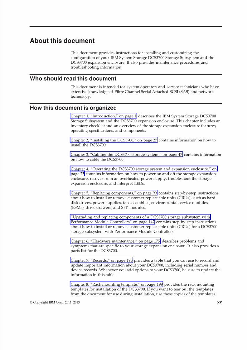
Chapter 1, “Introduction,” on page 1 describes the IBM System Storage DCS3700
Storage Subsystem and the DCS3700 expansion enclosure. This chapter includes aninventory checklist and an overview of the storage expansion enclosure features,operating specifications, and components.
Chapter 2, “Installing the DCS3700,” on page 27 contains information on how toinstall the DCS3700.
Chapter 3, “Cabling the DCS3700 storage system,” on page 47 contains informationon how to cable the DCS3700.
Chapter 4, “Operating the DCS3700 storage system and expansion enclosure,” onpage 75 contains information on how to power on and off the storage expansionenclosure, recover from an overheated power supply, troubleshoot the storage
expansion enclosure, and interpret LEDs.
Chapter 5, “Replacing components,” on page 99 contains step-by-step instructionsabout how to install or remove customer replaceable units (CRUs), such as harddisk drives, power supplies, fan assemblies, environmental service modules(ESMs), drive drawers, and SFP modules.
“Upgrading and replacing components of a DCS3700 storage subsystem withPerformance Module Controllers” on page 147 contains step-by-step instructionsabout how to install or remove customer replaceable units (CRUs) for a DCS3700storage subsystem with Performance Module Controllers.
Chapter 6, “Hardware maintenance,” on page 175 describes problems and
symptoms that are specific to your storage expansion enclosure. It also provides aparts list for the DCS3700.
Chapter 7, “Records,” on page 195 provides a table that you can use to record andupdate important information about your DCS3700, including serial number anddevice records. Whenever you add options to your DCS3700, be sure to update theinformation in this table.
Chapter 8, “Rack mounting template,” on page 199 provides the rack mountingtemplates for installation of the DCS3700. If you want to tear out the templatesfrom the document for use during installation, use these copies of the templates.
© Copyright IBM Corp. 2011, 2013 xv
8/9/2019 Installation, User's, And Maintenance
http://slidepdf.com/reader/full/installation-users-and-maintenance 16/262
Chapter 9, “Specifications for non-IBM rack installation,” on page 203 providessafety requirements and rack specifications for installing DCS3700 storagesubsystems and DCS3700 storage expansion enclosures into non-IBM racks.
Chapter 10, “Power cords,” on page 211 lists power cord information for theDCS3700.
Getting information, help, and service
If you need help, service, or technical assistance or just want more informationabout IBM products, you will find a wide variety of sources available from IBM toassist you. This section contains information about where to go for additionalinformation about IBM and IBM products, what to do if you experience a problemwith your system, and whom to call for service, if it is necessary.
Before you callBefore you call, take these steps to try to solve the problem yourself:v Check all cables to make sure that they are connected.v Check the power switches to make sure that the system is turned on.v Use the troubleshooting information in your system documentation, and use the
diagnostic tools that come with your system.v Check for technical information, hints, tips, and new device drivers at the IBM
System Storage Disk Support Web site pages that are listed in this section.v Use an IBM discussion forum on the IBM Web site to ask questions.
You can solve many problems without outside assistance by following thetroubleshooting procedures that IBM provides in the DS Storage Manager onlinehelp or in the documents that are provided with your system and software. Theinformation that comes with your system also describes the diagnostic tests thatyou can perform. Most subsystems, operating systems, and programs come withinformation that contains troubleshooting procedures and explanations of errormessages and error codes. If you suspect a software problem, see the informationfor the operating system or program.
Using the documentationInformation about your IBM system and preinstalled software, if any, is availablein the documents that come with your system; this includes printed books, onlinedocuments, README files, and help files. See the troubleshooting information inyour system documentation for instructions for using the diagnostic programs. Thetroubleshooting information or the diagnostic programs might tell you that youneed additional or updated device drivers or other software.
Finding Storage Manager software, controller firmware, andREADME files
DS Storage Manager software and controller firmware versions are available on theproduct DVD and can also be downloaded from the Web.
Important: Before you install DS Storage Manager software, consult the READMEfile. Updated README files contain the latest device driver versions, firmwarelevels, limitations, and other information not found in this document.
Storage Manager README files are found on the Web, at the following address:
xvi IBM System Storage DCS3700 Storage Subsystem: Installation, User's, and Maintenance Guide

8/9/2019 Installation, User's, And Maintenance
http://slidepdf.com/reader/full/installation-users-and-maintenance 17/262
http://www.ibm.com/support/entry/portal
To access the documentation related to your storage subsystem, operating system,and DS Storage Manager version from the IBM Support Portal, complete thefollowing steps:1. Go to http://www.ibm.com/support/entry/portal.
2. Under Choose your products, click Browse for a product or Search for aproduct.3. Under Choose your task, click Documentation.4. Under See your results, click View your page.
5. In the Product documentation box, click the link for the publication that youwant to access.
IBM System Storage Productivity CenterThe IBM System Storage Productivity Center (SSPC) is an integrated hardware andsoftware solution that provides a single point of entry for managing IBM SystemStorage, IBM System Storage SAN Volume Controller clusters, and othercomponents of your data storage infrastructure. Therefore, you can use the IBM
System Storage Productivity Center to manage multiple IBM System Storageproduct configurations from a single management interface.
To learn how to incorporate the DS Storage Manager with the IBM System StorageProductivity Center, see the IBM System Storage Productivity Center InformationCenter at the following Web site:
publib.boulder.ibm.com/infocenter/tivihelp/v4r1/index.jsp
Essential Web sites for DCS3700 support informationThe most up-to-date information about DCS3700 storage subsystems and DSStorage Manager, including documentation and the most recent software, firmware,
and NVSRAM downloads, can be found at the following Web site:1. Go to http://www.ibm.com/support/entry/portal.2. Under Choose your products, click Browse for a product or Search for a
product.
3. Under Choose your task, click Downloads.
4. Under See your results, click View your page.5. In the Downloads and fixes, click the link for the download that you want to
access.
Software service and supportThrough the IBM Support Line, for a fee you can get telephone assistance with
usage, configuration, and software problems. For information about whichproducts are supported by Support Line in your country or region, go to thefollowing Web site:
www.ibm.com/services/sl/products
For more information about the IBM Support Line and other IBM services, go tothe following Web sites:v www.ibm.com/servicesv www.ibm.com/planetwide
About this document xvii
8/9/2019 Installation, User's, And Maintenance
http://slidepdf.com/reader/full/installation-users-and-maintenance 18/262
Hardware service and supportYou can receive hardware service through IBM Integrated Technology Services orthrough your IBM reseller, if your reseller is authorized by IBM to providewarranty service. Go to the following Web site for support telephone numbers:
www.ibm.com/planetwide
In the U.S. and Canada, hardware service and support is available 24 hours a day,7 days a week. In the U.K., these services are available Monday through Friday,from 9 a.m. to 6 p.m.
Fire suppression systemsA fire suppression system is the responsibility of the customer. The customer's owninsurance underwriter, local fire marshal, or a local building inspector, or both,should be consulted in selecting a fire suppression system that provides the correctlevel of coverage and protection. IBM designs and manufactures equipment tointernal and external standards that require certain environments for reliableoperation. Because IBM does not test any equipment for compatibility with firesuppression systems, IBM does not make compatibility claims of any kind nordoes IBM provide recommendations on fire suppression systems.
xviii IBM System Storage DCS3700 Storage Subsystem: Installation, User's, and Maintenance Guide
8/9/2019 Installation, User's, And Maintenance
http://slidepdf.com/reader/full/installation-users-and-maintenance 19/262
Chapter 1. Introduction
This section describes the operating specifications, features, and components forthe IBM System Storage DCS3700 storage subsystem, DCS3700 expansion unit, and
DCS3700 storage subsystem with Performance Module Controllers.
Note: For Ethernet Interfaces: DCS3700 storage subsystem and DCS3700 storagesubsystem with Performance Module controllers are not intended to be connecteddirectly or indirectly by any means whatsoever to interfaces of publictelecommunication networks.
This chapter also includes an inventory checklist and important information about best practices guidelines and product updates for your DCS3700.
Overview
The DCS3700 Storage Subsystem is designed to meet the storage needs of highlyscalable, data streaming applications in high-performance computingenvironments.
The DCS3700 Storage Subsystem is designed to provide solutions to meet theneeds of midrange storage requirements, delivering high performance, advancedfunction, high availability, modular, and scalable storage capacity, withSAN-attached 6 Gbps Serial Attached SCSI (SAS) and 8 Gbps Fibre Channel (FC)connectivity, and support for RAID levels 0, 1, 3, 5, and 6. The storage subsystemoffers you data access and protection to meet your existing high-performancecomputing storage requirements and prepare for the future.
Note:
1. RAID 6 uses a P+Q design implementation.2. When RAID level 1 is implemented and the number of drives increases to more
than two, RAID level 10 is automatically implemented.
The DCS3700 Storage Subsystem supports attachment of the DCS3700 expansionenclosure. The DCS3700 supports configurations of SAS and Near-Line SAS disks,or a mix of these types of disk drives. For details on the maximum number of diskdrives supported, maximum storage capacity, and other features of the storagesubsystem, see “DCS3700 Features” on page 2.
The DCS3700 is a 4U rack-mountable storage enclosure that supports up to tworedundant, dual-active RAID storage controllers or environmental service modules,
depending on the model. As a standard, the DCS3700 storage subsystem RAIDcontrollers have two 6 Gbps x4 SAS host interface ports and a single 6 Gbps x4SAS expansion port on the base controller. Each controller has an additional slot inwhich you can install an optional Host Interface Card (HIC). The supported hostinterface cards are a four-port 8 Gbps Fibre Channel (FC) adapter or a two-port 6Gbps SAS adapter. Either host interface card can be used with the base SAS hostinterface. However, each controller must have the same type of host interface cardinstalled.
Advanced DCS3700 storage management, copy service options, and optionaladvanced disaster recovery functions are available, including FlashCopy®,
© Copyright IBM Corp. 2011, 2013 1
8/9/2019 Installation, User's, And Maintenance
http://slidepdf.com/reader/full/installation-users-and-maintenance 20/262
VolumeCopy, Enhanced Remote Mirroring, and Enhanced Global Mirroring. TheDS Storage Manager client is also available for the DCS3700 Storage Subsystem.This storage management software is designed to help centralize storagemanagement, simplify partitioning of the DCS3700 series storage into as many as128 virtual servers, and strategically allocate storage capacity to maximize storagespace.
SAS defined
The Serial Attached SCSI (SAS) is a point-to-point serial architecture that replacesthe parallel SCSI bus technology but still retains usage of the standard SCSIcommand set.
The SAS point-to-point architecture provides a dedicated, full-duplex channel thatcan transfer data at 6 Gbps in each direction. The Serial SCSI Protocol (SSP) is usedto support SAS-only drives.
Nearline SAS or NL-SAS drives are enterprise SATA drives that offer a native SASinterface. NL-SAS drives support dual I/O ports allowing for redundant datapaths, a faster interface compared to SATA, and the ability to support the SCSIcommand set.
Fibre Channel definedFibre Channel technology is a high-speed data transport technology that is usedfor mass storage and networking.
Fibre Channel technology is outlined in the SCSI-3 Fibre Channel Protocol(SCSI-FCP) standard.
Using a Fibre Channel arbitrated loop (FC-AL), more than 100 Fibre Channeldevices can be supported, compared to 15 small computer system interface (SCSI)devices.
Operating system supportFor supported operating systems, see the latest System README file.
For additional host operating system support, refer to the IBM DCS3700 product atthe following website:
www.ibm.com/systems/support/storage/config/ssic/index.jsp
See “Finding Storage Manager software, controller firmware, and README files”on page xvi to learn how to access the DCS3700 README files on the web.
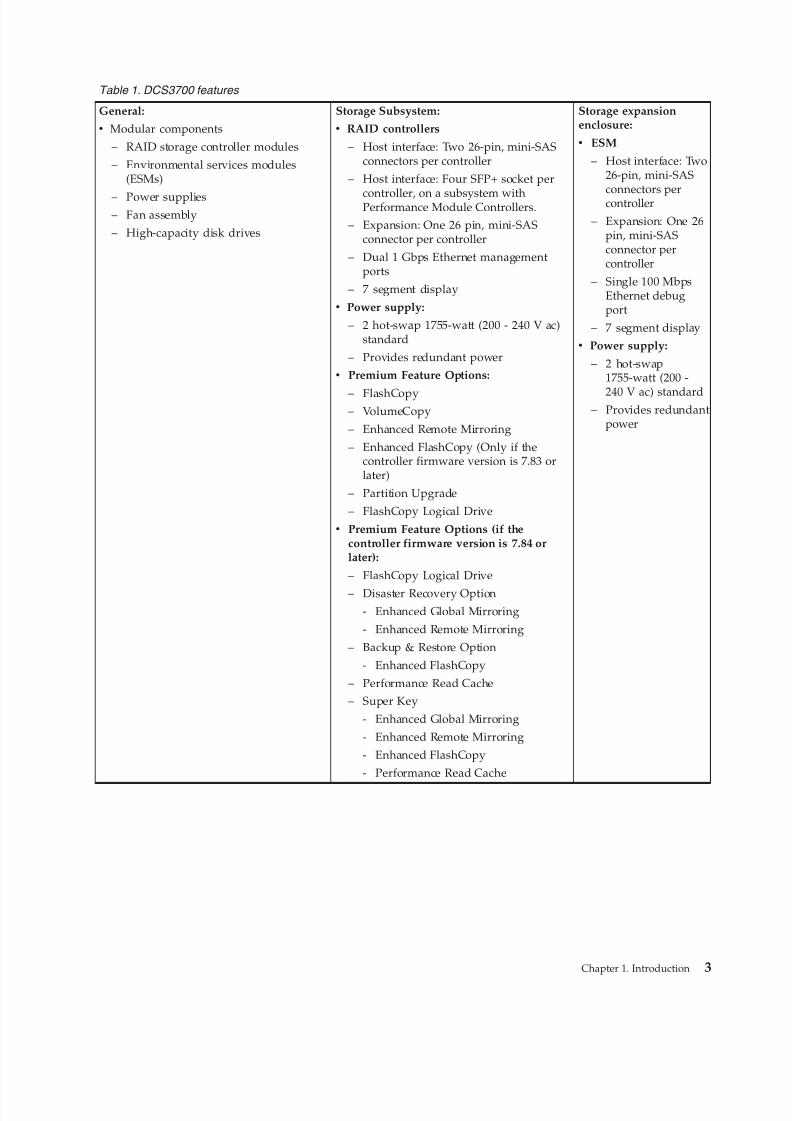
DCS3700 FeaturesA table summarizes the features of the DCS3700 storage subsystem and expansionenclosure.
For a list of the operating specifications, such as weight, height, and heat output,see “Specifications” on page 20.
2 IBM System Storage DCS3700 Storage Subsystem: Installation, User's, and Maintenance Guide
8/9/2019 Installation, User's, And Maintenance
http://slidepdf.com/reader/full/installation-users-and-maintenance 21/262
Table 1. DCS3700 features
General:
v Modular components
– RAID storage controller modules
– Environmental services modules(ESMs)
– Power supplies– Fan assembly
– High-capacity disk drives
Storage Subsystem:
v RAID controllers
– Host interface: Two 26-pin, mini-SASconnectors per controller
– Host interface: Four SFP+ socket per
controller, on a subsystem withPerformance Module Controllers.
– Expansion: One 26 pin, mini-SASconnector per controller
– Dual 1 Gbps Ethernet managementports
– 7 segment display
v Power supply:
– 2 hot-swap 1755-watt (200 - 240 V ac)standard
– Provides redundant power
v Premium Feature Options:
– FlashCopy– VolumeCopy
– Enhanced Remote Mirroring
– Enhanced FlashCopy (Only if thecontroller firmware version is 7.83 orlater)
– Partition Upgrade
– FlashCopy Logical Drive
v Premium Feature Options (if thecontroller firmware version is 7.84 orlater):
– FlashCopy Logical Drive
– Disaster Recovery Option- Enhanced Global Mirroring
- Enhanced Remote Mirroring
– Backup & Restore Option
- Enhanced FlashCopy
– Performance Read Cache
– Super Key
- Enhanced Global Mirroring
- Enhanced Remote Mirroring
- Enhanced FlashCopy
- Performance Read Cache
Storage expansionenclosure:
v ESM
– Host interface: Two26-pin, mini-SASconnectors percontroller
– Expansion: One 26pin, mini-SASconnector percontroller
– Single 100 MbpsEthernet debugport
– 7 segment display
v Power supply:
– 2 hot-swap1755-watt (200 -
240 V ac) standard– Provides redundant
power
Chapter 1. Introduction 3
8/9/2019 Installation, User's, And Maintenance
http://slidepdf.com/reader/full/installation-users-and-maintenance 22/262
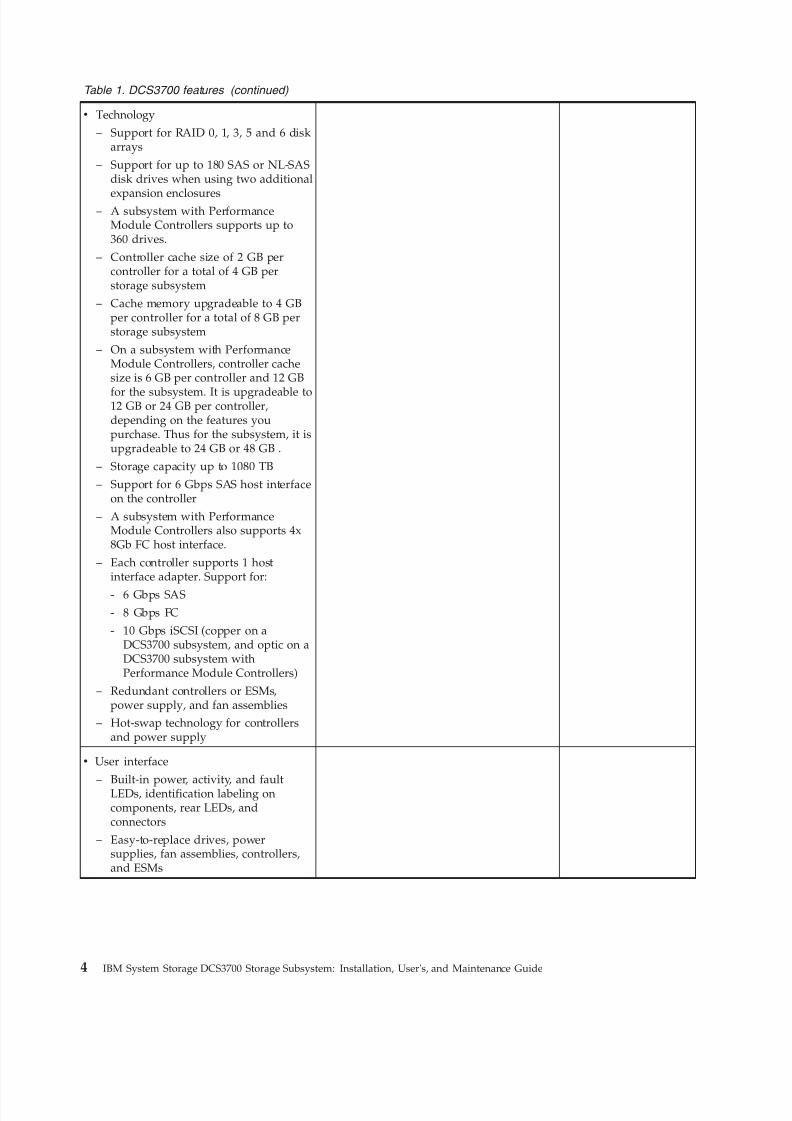
Table 1. DCS3700 features (continued)
v Technology
– Support for RAID 0, 1, 3, 5 and 6 diskarrays
– Support for up to 180 SAS or NL-SASdisk drives when using two additional
expansion enclosures– A subsystem with Performance
Module Controllers supports up to360 drives.
– Controller cache size of 2 GB percontroller for a total of 4 GB perstorage subsystem
– Cache memory upgradeable to 4 GBper controller for a total of 8 GB perstorage subsystem
– On a subsystem with PerformanceModule Controllers, controller cachesize is 6 GB per controller and 12 GB
for the subsystem. It is upgradeable to12 GB or 24 GB per controller,depending on the features youpurchase. Thus for the subsystem, it isupgradeable to 24 GB or 48 GB .
– Storage capacity up to 1080 TB
– Support for 6 Gbps SAS host interfaceon the controller
– A subsystem with PerformanceModule Controllers also supports 4x8Gb FC host interface.
– Each controller supports 1 hostinterface adapter. Support for:
- 6 Gbps SAS- 8 Gbps FC
- 10 Gbps iSCSI (copper on aDCS3700 subsystem, and optic on aDCS3700 subsystem withPerformance Module Controllers)
– Redundant controllers or ESMs,power supply, and fan assemblies
– Hot-swap technology for controllersand power supply
v User interface
– Built-in power, activity, and faultLEDs, identification labeling oncomponents, rear LEDs, andconnectors
– Easy-to-replace drives, powersupplies, fan assemblies, controllers,and ESMs
4 IBM System Storage DCS3700 Storage Subsystem: Installation, User's, and Maintenance Guide
8/9/2019 Installation, User's, And Maintenance
http://slidepdf.com/reader/full/installation-users-and-maintenance 23/262
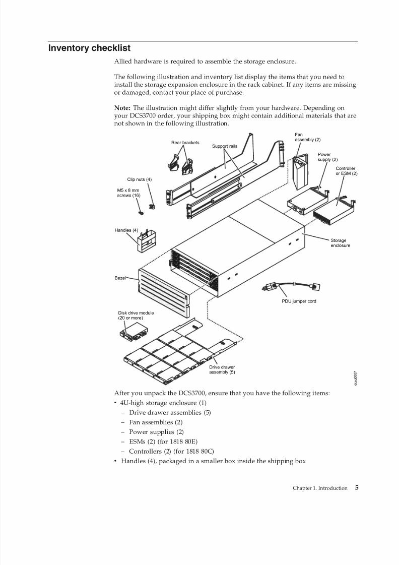
Inventory checklist
Allied hardware is required to assemble the storage enclosure.
The following illustration and inventory list display the items that you need toinstall the storage expansion enclosure in the rack cabinet. If any items are missingor damaged, contact your place of purchase.
Note: The illustration might differ slightly from your hardware. Depending onyour DCS3700 order, your shipping box might contain additional materials that arenot shown in the following illustration.
Support rails
Storageenclosure
M5 x 8 mmscrews (16)
PDU jumper cord
Rear brackets
Bezel
Clip nuts (4)
Fanassembly (2)
Power supply (2)
Controller or ESM (2)
Drive drawer assembly (5)
Disk drive module(20 or more)
Handles (4)
d c s q
0 0 0 7
After you unpack the DCS3700, ensure that you have the following items:v 4U-high storage enclosure (1)
– Drive drawer assemblies (5)– Fan assemblies (2)– Power supplies (2)– ESMs (2) (for 1818 80E)– Controllers (2) (for 1818 80C)
v Handles (4), packaged in a smaller box inside the shipping box
Chapter 1. Introduction 5
8/9/2019 Installation, User's, And Maintenance
http://slidepdf.com/reader/full/installation-users-and-maintenance 24/262
v DDMs (20 or more, depending on your DCS3700 order), packaged in a smaller box inside the shipping box
v Bezel (1)v Rack-mounting hardware kit (1), packaged in a smaller box inside the shipping
box, including:– Rails (2), right and left assembly
– Rear brackets (2)– M5 black hex-head slotted screws (16)
Note: The screws are either preinstalled in the support rails or packaged in aplastic bag.
– Washers (8)– Clip nuts (4)
Important: The DCS3700 does not ship with region-specific ac power cords. Youmust obtain the IBM-approved power cords for your region. For more information,see Chapter 10, “Power cords,” on page 211.
Receiving product updates and support notificationsDownload the latest versions of these packages at the time of initial installationand when product updates become available.v DS Storage Manager host softwarev DCS3700 storage subsystem controller firmware and NVSRAMv DCS3700 expansion unit ESM firmwarev Drive firmware
Important
Keep your system up-to-date with the latest firmware and other product updates
by subscribing to support notifications.
For more information about how to register for support notifications, see the StayInformed section of the IBM Disk Support website.
Best practices guidelinesIBM recommends guidelines/best practices for optimal operation of yoursubsystem.v Ensure that your system is in an optimal state before you shut it down. Never
turn off the power if any Service Action Required LED is lit. Ensure that youresolve any error conditions before you shut down the system.
v Back up the data on your storage drives periodically.v To maintain power redundancy, plug the right and left power supplies of the
DCS3700 storage subsystem into two independent external power circuitsthrough the distribution units that are inside a rack cabinet or directly intoexternal receptacles. The DCS3700 storage subsystem and all its attachedexpansion enclosures can then have power in the event that only one powercircuit is available. Also, during an unattended restoration of power, the storagedevices in the configuration can power on simultaneously.
Note: Do not overload the circuits that power your storage subsystem andstorage expansion enclosures. Use additional pairs of power distribution units
6 IBM System Storage DCS3700 Storage Subsystem: Installation, User's, and Maintenance Guide
8/9/2019 Installation, User's, And Maintenance
http://slidepdf.com/reader/full/installation-users-and-maintenance 25/262
(PDUs) if necessary. Refer to Table 10 on page 23 for information about storageexpansion enclosure power requirements. Contact your IBM servicerepresentative for additional information.
v Before a planned system shutdown or after system additions, removals, ormodifications (including firmware updates, logical drive creations, storagepartitioning definitions, hardware changes, and so on), complete the followingtasks:
1. Save the storage subsystem profile.2. Save the storage subsystem configuration.3. Save the Collect All Support Data (CASD).Ensure that you save the files in a location other than in the logical drives,which were created for the storage subsystem.For more information about how to complete these tasks, check the DS StorageManager online help or the DS Storage Manager guide for your operatingsystem.
v During any maintenance or attended power-up procedure, carefully follow thepower-up sequence listed in “Restoring power after an unexpected shutdown”on page 94. Ensure that each component of the subsystem is powered up in the
correct order, so that the controller can optimally access all the storagesubsystems.
v The storage subsystem supports simultaneous power-up to the systemcomponents. However, you must always follow the power-up sequence listed in“Restoring power after an unexpected shutdown” on page 94.
v A storage system in an optimal state should recover automatically from anunexpected shutdown and an unattended restoration of power to systemcomponents. After power is restored, call IBM support if any of the followingconditions occur:– The storage subsystem logical drives and subsystems do not display in the
DS Storage Manager graphical user interface (GUI).– The storage subsystem logical drives and subsystems are not online.– The storage subsystem logical drives and subsystems are degraded.
DCS3700 components
Field Replacable Components (FRUs) of the DCS3700 subsystem and an Isometricview of the subsystem.
The DCS3700 storage subsystem directs and manages the I/O activity between ahost and the drives in a RAID array. The DCS3700 expansion unit providesadditional storage capacity to the storage system.
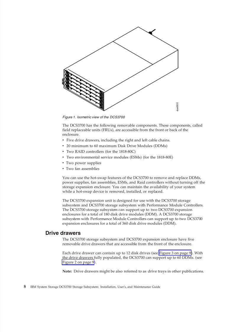
Figure 1 on page 8 shows the DCS3700 unit without the front bezel in place.
Note: The illustrations in this document might differ slightly from your hardware.
Chapter 1. Introduction 7
8/9/2019 Installation, User's, And Maintenance
http://slidepdf.com/reader/full/installation-users-and-maintenance 26/262
The DCS3700 has the following removable components. These components, calledfield replaceable units (FRUs), are accessible from the front or back of theenclosure.v Five drive drawers, including the right and left cable chains.v 20 minimum to 60 maximum Disk Drive Modules (DDMs)v Two RAID controllers (for the 1818-80C)v Two environmental service modules (ESMs) (for the 1818-80E)v Two power suppliesv Two fan assemblies
You can use the hot-swap features of the DCS3700 to remove and replace DDMs,power supplies, fan assemblies, ESMs, and Raid controllers without turning off thestorage expansion enclosure. You can maintain the availability of your systemwhile a hot-swap device is removed, installed, or replaced.
The DCS3700 expansion unit is designed for use with the DCS3700 storagesubsystem and DCS3700 storage subsystem with Performance Module Controllers.The DCS3700 storage subsystem can support up to two DCS3700 expansionenclosures for a total of 180 disk drive modules (DDM). A DCS3700 storagesubsystem with Performance Module Controllers can support up to two DCS3700expansion enclosures for a total of 360 disk drive modules (DDM).
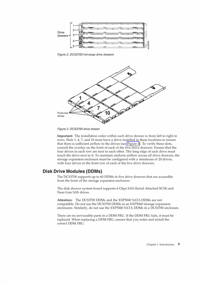
Drive drawersThe DCS3700 storage subsystem and DCS3700 expansion enclosure have fiveremovable drive drawers that are accessible from the front of the enclosure.
Each drive drawer can contain up to 12 disk drives (see Figure 3 on page 9). Withthe drive drawers fully populated, the DCS3700 can support up to 60 DDMs. (seeFigure 2 on page 9).
Note: Drive drawers might be also referred to as drive trays in other publications.
d c s i 0 0 3 1
Figure 1. Isometric view of the DCS3700
8 IBM System Storage DCS3700 Storage Subsystem: Installation, User's, and Maintenance Guide
8/9/2019 Installation, User's, And Maintenance
http://slidepdf.com/reader/full/installation-users-and-maintenance 27/262
Important: The installation order within each drive drawer is from left to right inrows. Slots 1, 4, 7, and 10 must have a drive installed in these locations to ensurethat there is sufficient airflow to the drives (see Figure 3). To verify these slots,
consult the overlay on the front of each of the five drive drawers. Ensure that thefour drives in each row are next to each other. The long edge of each drive musttouch the drive next to it. To maintain uniform airflow across all drive drawers, thestorage expansion enclosure must be configured with a minimum of 20 drives,with four drives in the front row of each of the five drive drawers.
Disk Drive Modules (DDMs)The DCS3700 supports up to 60 DDMs in five drive drawers that are accessiblefrom the front of the storage expansion enclosure.
The disk drawer system board supports 6 Gbps SAS (Serial Attached SCSI) andNear-Line SAS drives.
Attention: The DCS3700 DDMs and the EXP5060 SATA DDMs are notcompatible. Do not use the DCS3700 DDMs in an EXP5060 storage expansionenclosures. Similarly, do not use the EXP5060 SATA DDMs in a DCS3700 enclosure.
There are no serviceable parts in a DDM FRU. If the DDM FRU fails, it must bereplaced. When replacing a DDM FRU, ensure that you order and install thecorrect DDM FRU.
Drivedrawers
1
2
3
4
5 d c s q 0 0 0 4
Figure 2. DCS3700 hot-swap drive drawers
Front-rowdrives
Figure 3. DCS3700 drive drawer
Chapter 1. Introduction 9

8/9/2019 Installation, User's, And Maintenance
http://slidepdf.com/reader/full/installation-users-and-maintenance 28/262
Attention:
1. After you remove a drive FRU, wait 90 seconds before replacing or reseatingthe drive FRU to allow the drive to properly spin down. Failure to do so cancause undesired events.
2. Never hot-swap a drive FRU when its green Activity LED is flashing. Hot-swapa drive FRU only when its associated blue Service Action Allowed LED is lit
and the drive is inactive.If the DDM you want to remove is not in a failed or bypass state, always use theDS Storage Manager client program either to place the DDM in a failed state or toplace the array that is associated with the DDM (or DDMs) in an offline state
before you remove it from the enclosure.
ControllersThe DCS3700 storage subsystem (1818-80C) has two redundant controllers, whichcan be hot-swapped.
The controllers contain the storage subsystem control logic, interface ports, andLEDs. The controllers install from the rear of the storage enclosure. Controller A isinstalled in storage bridge bay slot A (SBB A) and controller B is installed instorage bridge bay slot B (SBB B). All connections to the hosts and the expansionenclosures are made through the controllers. Figure 4 shows the location of thecontrollers in the DCS3700.
Note: To preserve optimal airflow, do not remove a failed controller FRU from theDCS3700 chassis until you are ready to replace it with a new FRU.
Information about the condition of the controllers is conveyed by indicator LEDson the controller. See “Controller LEDs” on page 82 for more information about theLEDs found on the RAID controller.
Controller cable connectionsThe SAS ports, Ethernet ports, and the optional HIC on a DCS3700 subsystem anda DCS3700 subsystem with Performance Module Controllers are depicted with adiagram.
Each controller contains the following connections:v Two 6 Gbps x4 SAS host ports
ACDC
2
1
I
O
ACDC
2
1
I
O
Controller or ESM
SBB A
Controller or ESM
SBB B
d c s i 0 0 3 0
Figure 4. Location of the DCS3700 controllers
10 IBM System Storage DCS3700 Storage Subsystem: Installation, User's, and Maintenance Guide
8/9/2019 Installation, User's, And Maintenance
http://slidepdf.com/reader/full/installation-users-and-maintenance 29/262
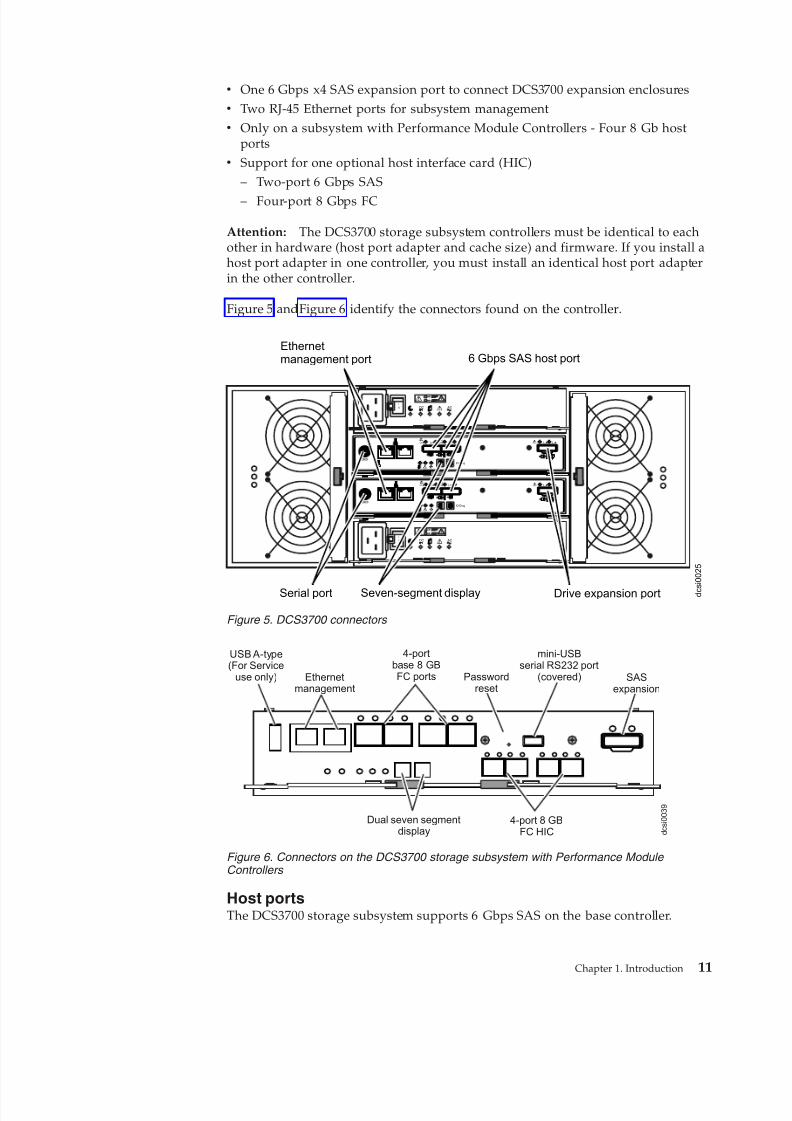
v One 6 Gbps x4 SAS expansion port to connect DCS3700 expansion enclosuresv Two RJ-45 Ethernet ports for subsystem managementv Only on a subsystem with Performance Module Controllers - Four 8 Gb host
portsv Support for one optional host interface card (HIC)
– Two-port 6 Gbps SAS
– Four-port 8 Gbps FC
Attention: The DCS3700 storage subsystem controllers must be identical to eachother in hardware (host port adapter and cache size) and firmware. If you install ahost port adapter in one controller, you must install an identical host port adapterin the other controller.
Figure 5 andFigure 6 identify the connectors found on the controller.
Host portsThe DCS3700 storage subsystem supports 6 Gbps SAS on the base controller.
d c s
i 0 0 2 5
Ethernetmanagement port 6 Gbps SAS host port
Drive expansion portSerial port Seven-segment display
Lnk Lnk Lnk Lnk
ID/Diag
L nk L nk
Lnk Lnk Lnk Lnk
ID/Diag
L nk L nk
ACDC
2
1
I
O
ACDC
2
1
I
O
Figure 5. DCS3700 connectors
SASexpansion
mini-USBserial RS232 port
(covered)Passwordreset
4-portbase 8 GBFC portsEthernet
management
USB A-type(For Service
use only)
d c s i 0 0 3 9
4-port 8 GBFC HIC
Dual seven segmentdisplay
Figure 6. Connectors on the DCS3700 storage subsystem with Performance Module Controllers
Chapter 1. Introduction 11
8/9/2019 Installation, User's, And Maintenance
http://slidepdf.com/reader/full/installation-users-and-maintenance 30/262
The controller also contains an upgradeable interface slot that can support anoptional 6 Gbps two-port SAS host interface card or 8 Gbps four-port FC hostinterface card.
The controller host interface ports automatically negotiate link speed when theyare connected to a host or a switch. The host ports can operate at the followingspeeds:v 6 Gbps SAS host ports can operate at either 3 or 6 Gbpsv 8 Gbps FC host ports can operate at 2, 4, or 8 Gbps
The controller performs link speed negotiation during the following events:v Controller reaches a fully powered-up statev Detection of a link-up event following a link-down event
Expansion portsEach controller has a single 6 Gbps x4 SAS expansion port that is used to connectexpansion enclosures to the storage system.
The two SAS expansion ports (one on each controller) are used to form a
redundant drive channel.
Ethernet management portsDefault IP addresses are assigned to the two ports on controllers A and B.
The Ethernet connections provide for out-of-band management of the controller.Each controller has two RJ-45 Ethernet ports that support either 100Base-T or1000Base-T connections.
One Ethernet port on each controller is used for daily management of the storagesubsystem. The second port is reserved for service personnel or acts as a backupport if the primary port fails.
The default IP addresses for the Ethernet ports are as follows:v Port 1 on controller A is 192.168.128.101v Port 2 on controller A is 192.168.129.101v Port 1 on controller B is 192.168.128.102v Port 2 on controller B is 192.168.129.102
The subnet mask for all Ethernet ports is 255.255.255.0.
Serial portThe serial port on each controller uses a 6-pin Mini-DIN connector. This port isintended to be used by service personnel only to provide diagnostic operations on
the RAID controllers.The maximum baud rate is 115200 bps and the factory default baud rate is 38400
bps.
Attention: Incorrect use of the serial port can result in loss of data access and, insome cases, in loss of data. Do not make any connections to the serial port unlessyou do so under the direct guidance of IBM support personnel.
12 IBM System Storage DCS3700 Storage Subsystem: Installation, User's, and Maintenance Guide
8/9/2019 Installation, User's, And Maintenance
http://slidepdf.com/reader/full/installation-users-and-maintenance 31/262
Cache memoryThe data cache memory is a buffer used to temporarily store hard disk drive dataduring data read and write operations.
Each RAID controller has data cache memory. The Cache Active LED on thecontroller turns on when the cache contains data that is not written to the harddisk drives. The Cache Active LED is off when there is no data stored in cache.
The DCS3700 storage subsystem is available with either 4 GB (2 GB per controller)or 8 GB (4 GB per controller) of cache memory. The DCS3700 storage subsystemwith Performance Module Controllers is available with a cache memory of 6 GBper controller, upgradeable to 12 GB or 24 GB. Thus, the DCS3700 storagesubsystem with Performance Module Controllers comes with a cache of 12 GBwhich can be upgraded up to 24 GB or 48 GB.
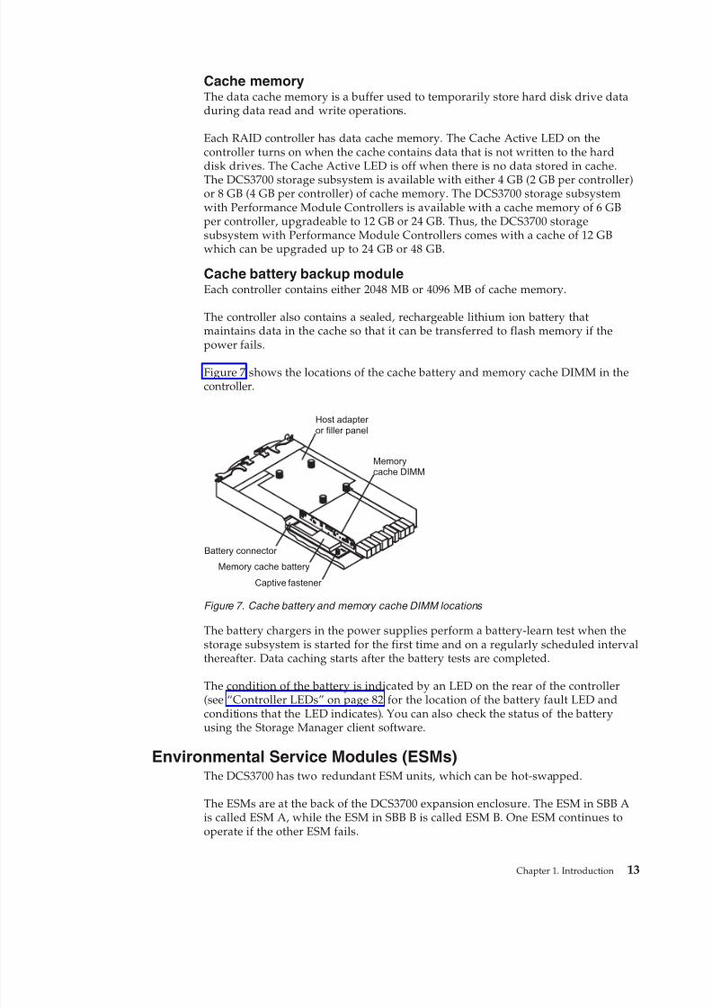
Cache battery backup moduleEach controller contains either 2048 MB or 4096 MB of cache memory.
The controller also contains a sealed, rechargeable lithium ion battery thatmaintains data in the cache so that it can be transferred to flash memory if thepower fails.
Figure 7 shows the locations of the cache battery and memory cache DIMM in thecontroller.
The battery chargers in the power supplies perform a battery-learn test when thestorage subsystem is started for the first time and on a regularly scheduled intervalthereafter. Data caching starts after the battery tests are completed.
The condition of the battery is indicated by an LED on the rear of the controller
(see “Controller LEDs” on page 82 for the location of the battery fault LED andconditions that the LED indicates). You can also check the status of the batteryusing the Storage Manager client software.
Environmental Service Modules (ESMs)The DCS3700 has two redundant ESM units, which can be hot-swapped.
The ESMs are at the back of the DCS3700 expansion enclosure. The ESM in SBB Ais called ESM A, while the ESM in SBB B is called ESM B. One ESM continues tooperate if the other ESM fails.
Battery connector
Captive fastener
Memory cache battery
Memorycache DIMM
Host adapter or filler panel
Figure 7. Cache battery and memory cache DIMM locations
Chapter 1. Introduction 13
8/9/2019 Installation, User's, And Maintenance
http://slidepdf.com/reader/full/installation-users-and-maintenance 32/262
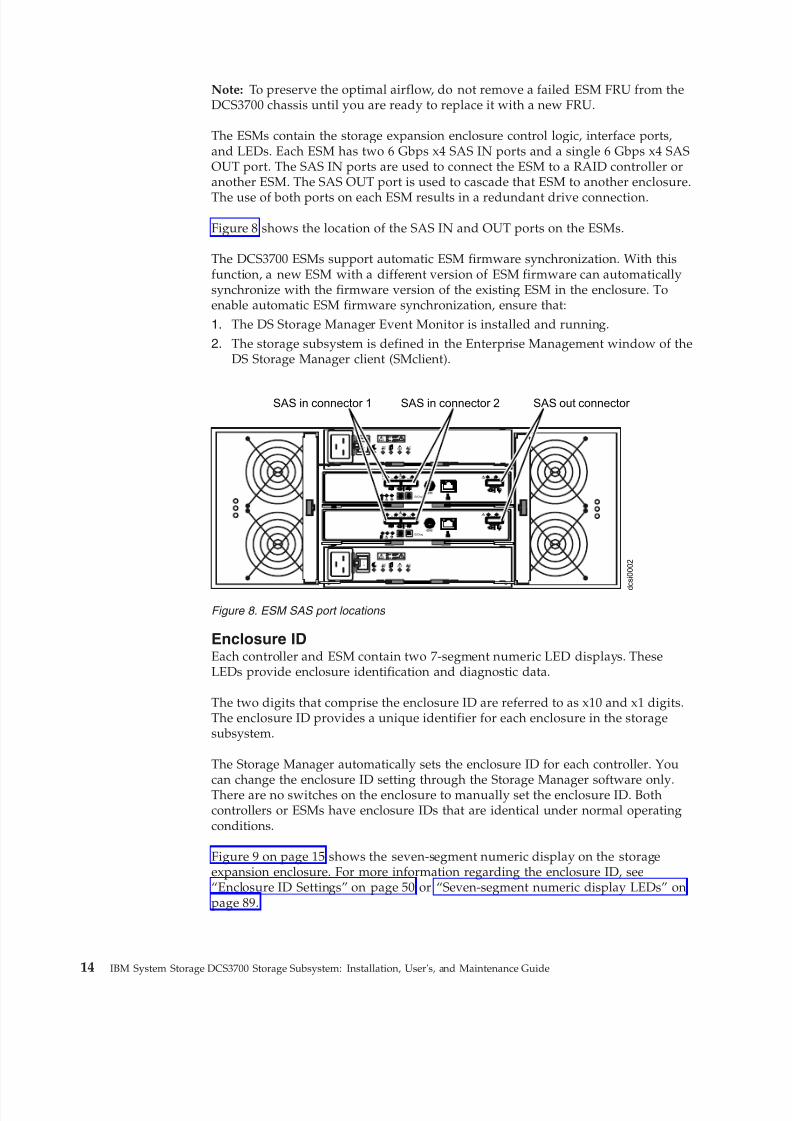
Note: To preserve the optimal airflow, do not remove a failed ESM FRU from theDCS3700 chassis until you are ready to replace it with a new FRU.
The ESMs contain the storage expansion enclosure control logic, interface ports,and LEDs. Each ESM has two 6 Gbps x4 SAS IN ports and a single 6 Gbps x4 SASOUT port. The SAS IN ports are used to connect the ESM to a RAID controller oranother ESM. The SAS OUT port is used to cascade that ESM to another enclosure.
The use of both ports on each ESM results in a redundant drive connection.
Figure 8 shows the location of the SAS IN and OUT ports on the ESMs.
The DCS3700 ESMs support automatic ESM firmware synchronization. With thisfunction, a new ESM with a different version of ESM firmware can automaticallysynchronize with the firmware version of the existing ESM in the enclosure. Toenable automatic ESM firmware synchronization, ensure that:
1. The DS Storage Manager Event Monitor is installed and running.
2. The storage subsystem is defined in the Enterprise Management window of theDS Storage Manager client (SMclient).
Enclosure IDEach controller and ESM contain two 7-segment numeric LED displays. TheseLEDs provide enclosure identification and diagnostic data.
The two digits that comprise the enclosure ID are referred to as x10 and x1 digits.The enclosure ID provides a unique identifier for each enclosure in the storagesubsystem.
The Storage Manager automatically sets the enclosure ID for each controller. You
can change the enclosure ID setting through the Storage Manager software only.There are no switches on the enclosure to manually set the enclosure ID. Bothcontrollers or ESMs have enclosure IDs that are identical under normal operatingconditions.
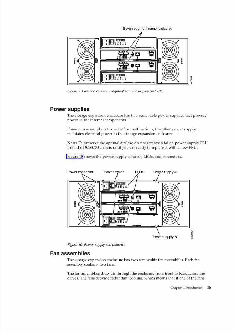
Figure 9 on page 15 shows the seven-segment numeric display on the storageexpansion enclosure. For more information regarding the enclosure ID, see“Enclosure ID Settings” on page 50 or “Seven-segment numeric display LEDs” onpage 89.
d
c s i 0 0 0 2
Lnk Lnk Lnk Lnk
ID/Diag
L nk L nk
Lnk Lnk Lnk Lnk
ID/Diag
L nk L nk
ACDC
2
1
I
O
ACDC
2
1
I
O
SAS out connector SAS in connector 2SAS in connector 1
Figure 8. ESM SAS port locations
14 IBM System Storage DCS3700 Storage Subsystem: Installation, User's, and Maintenance Guide
8/9/2019 Installation, User's, And Maintenance
http://slidepdf.com/reader/full/installation-users-and-maintenance 33/262
Power supplies
The storage expansion enclosure has two removable power supplies that providepower to the internal components.
If one power supply is turned off or malfunctions, the other power supplymaintains electrical power to the storage expansion enclosure.
Note: To preserve the optimal airflow, do not remove a failed power supply FRUfrom the DCS3700 chassis until you are ready to replace it with a new FRU.
Figure 10 shows the power supply controls, LEDs, and connectors.
Fan assembliesThe storage expansion enclosure has two removable fan assemblies. Each fanassembly contains two fans.
The fan assemblies draw air through the enclosure from front to back across thedrives. The fans provide redundant cooling, which means that if one of the fans
d c s i 0 0 0 1
Lnk Lnk Lnk Lnk
ID/Diag
L nk L nk
Lnk Lnk Lnk Lnk
ID/Diag
L nk L nk
ACDC
2
1
I
O
ACDC
2
1
I
O
Seven-segment numeric display
Figure 9. Location of seven-segment numeric display on ESM
d c s i 0 0
0 4
Lnk Lnk Lnk Lnk
ID/Diag
L nk L nk
Lnk Lnk L nk L nk
ID/Diag
L nk L nk
ACDC
2
1
I
O
ACDC
2
1
I
O
Power connector Power supply APower switch LEDs
Power supply B
Figure 10. Power supply components
Chapter 1. Introduction 15
8/9/2019 Installation, User's, And Maintenance
http://slidepdf.com/reader/full/installation-users-and-maintenance 34/262
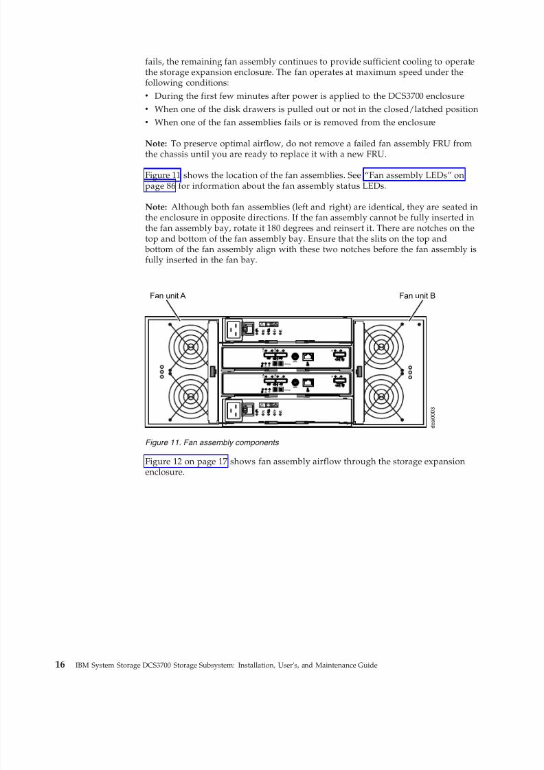
fails, the remaining fan assembly continues to provide sufficient cooling to operatethe storage expansion enclosure. The fan operates at maximum speed under thefollowing conditions:v During the first few minutes after power is applied to the DCS3700 enclosurev When one of the disk drawers is pulled out or not in the closed/latched positionv When one of the fan assemblies fails or is removed from the enclosure
Note: To preserve optimal airflow, do not remove a failed fan assembly FRU fromthe chassis until you are ready to replace it with a new FRU.
Figure 11 shows the location of the fan assemblies. See “Fan assembly LEDs” onpage 86 for information about the fan assembly status LEDs.
Note: Although both fan assemblies (left and right) are identical, they are seated inthe enclosure in opposite directions. If the fan assembly cannot be fully inserted inthe fan assembly bay, rotate it 180 degrees and reinsert it. There are notches on thetop and bottom of the fan assembly bay. Ensure that the slits on the top and
bottom of the fan assembly align with these two notches before the fan assembly isfully inserted in the fan bay.
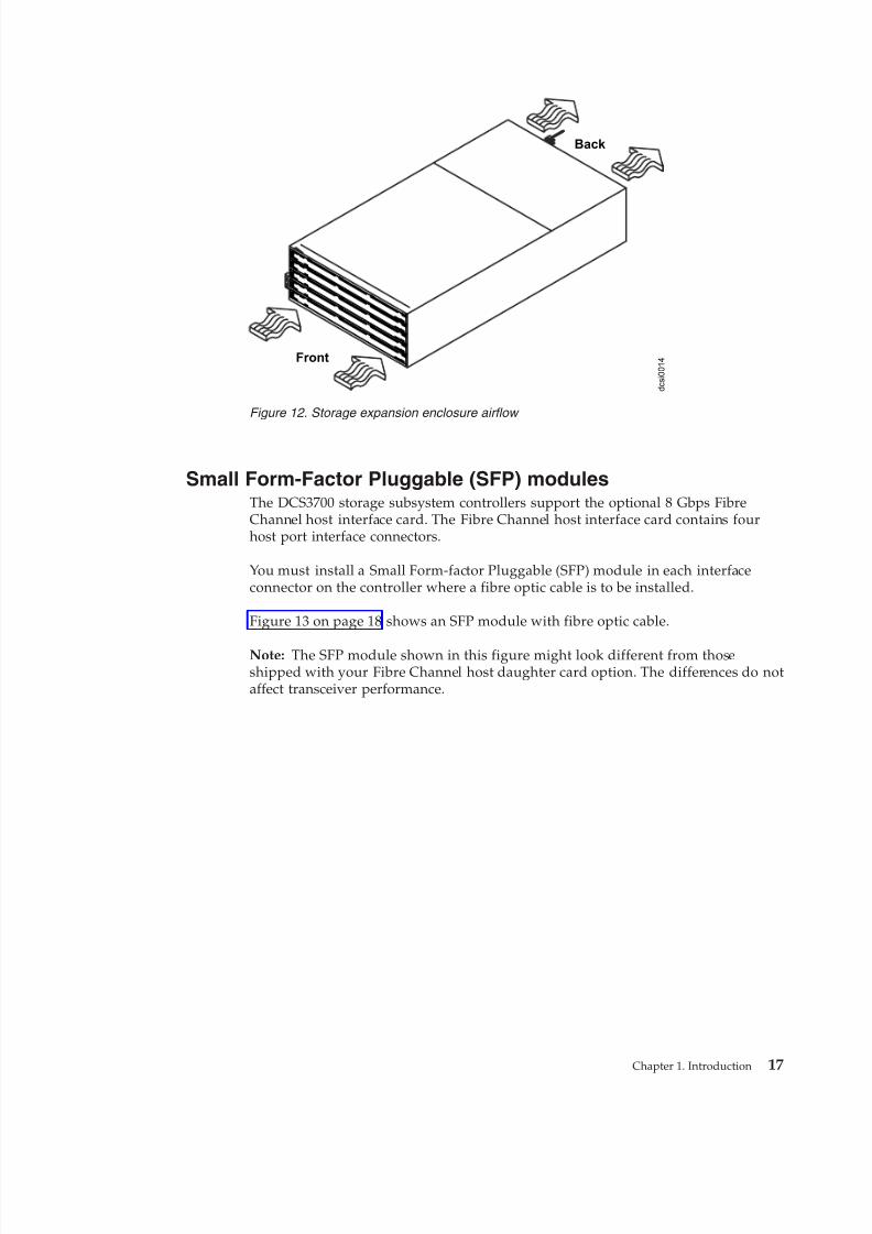
Figure 12 on page 17 shows fan assembly airflow through the storage expansionenclosure.
d c s i 0 0 0 3
Lnk Lnk Lnk Lnk
ID/Diag
L nk L nk
Lnk Lnk Ln k Ln k
ID/Diag
L nk L nk
ACDC
2
1
I
O
ACDC
2
1
I
O
Fan unit A Fan unit B
Figure 11. Fan assembly components
16 IBM System Storage DCS3700 Storage Subsystem: Installation, User's, and Maintenance Guide
8/9/2019 Installation, User's, And Maintenance
http://slidepdf.com/reader/full/installation-users-and-maintenance 35/262
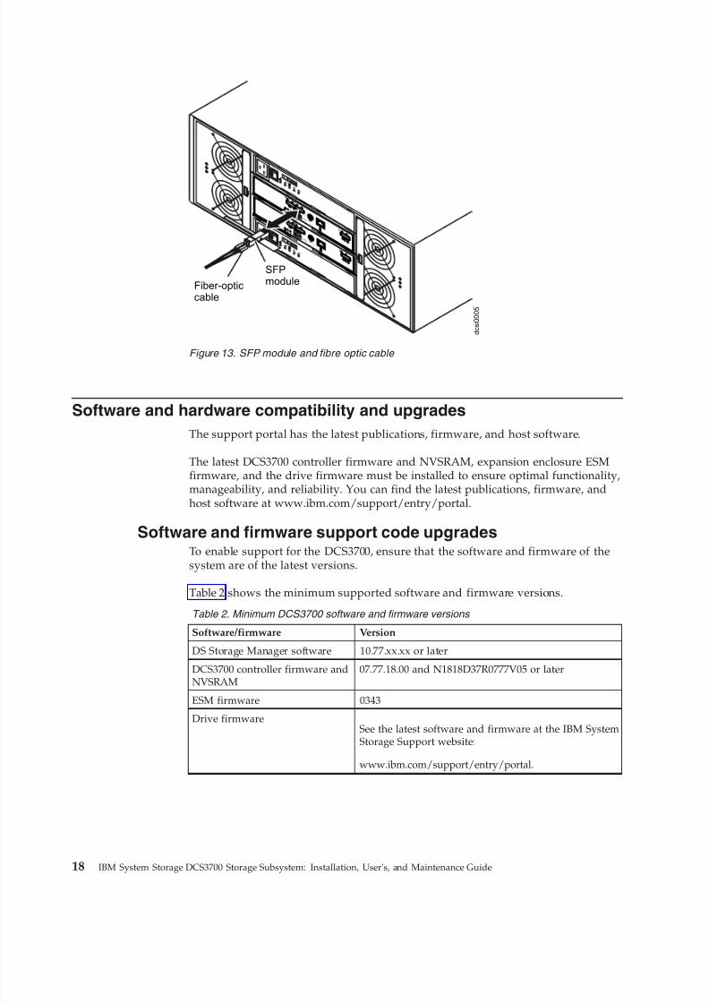
Small Form-Factor Pluggable (SFP) modulesThe DCS3700 storage subsystem controllers support the optional 8 Gbps FibreChannel host interface card. The Fibre Channel host interface card contains fourhost port interface connectors.
You must install a Small Form-factor Pluggable (SFP) module in each interfaceconnector on the controller where a fibre optic cable is to be installed.
Figure 13 on page 18 shows an SFP module with fibre optic cable.
Note: The SFP module shown in this figure might look different from thoseshipped with your Fibre Channel host daughter card option. The differences do notaffect transceiver performance.
Front
Back
d c s i 0 0 1 4
Figure 12. Storage expansion enclosure airflow
Chapter 1. Introduction 17
8/9/2019 Installation, User's, And Maintenance
http://slidepdf.com/reader/full/installation-users-and-maintenance 36/262
Software and hardware compatibility and upgrades
The support portal has the latest publications, firmware, and host software.
The latest DCS3700 controller firmware and NVSRAM, expansion enclosure ESMfirmware, and the drive firmware must be installed to ensure optimal functionality,manageability, and reliability. You can find the latest publications, firmware, andhost software at www.ibm.com/support/entry/portal.
Software and firmware support code upgradesTo enable support for the DCS3700, ensure that the software and firmware of thesystem are of the latest versions.
Table 2 shows the minimum supported software and firmware versions.
Table 2. Minimum DCS3700 software and firmware versions
Software/firmware Version
DS Storage Manager software 10.77.xx.xx or later
DCS3700 controller firmware andNVSRAM
07.77.18.00 and N1818D37R0777V05 or later
ESM firmware 0343Drive firmware
See the latest software and firmware at the IBM SystemStorage Support website:
www.ibm.com/support/entry/portal.
Lnk
LnkLnk
Lnk
ID/Diag
LnkLnk
Lnk
LnkLnk
Lnk
ID/Diag
LnkLnk
AC
DC
2
1
I
O
AC
DC
2
1
I
O
Fiber-opticcable
SFPmodule
d c s i 0 0 0 5
Figure 13. SFP module and fibre optic cable
18 IBM System Storage DCS3700 Storage Subsystem: Installation, User's, and Maintenance Guide
8/9/2019 Installation, User's, And Maintenance
http://slidepdf.com/reader/full/installation-users-and-maintenance 37/262
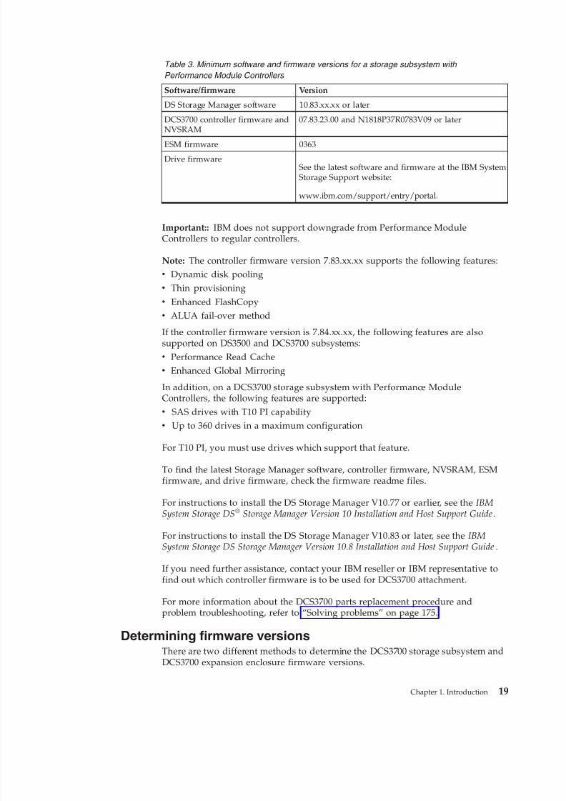
Table 3. Minimum software and firmware versions for a storage subsystem with
Performance Module Controllers
Software/firmware Version
DS Storage Manager software 10.83.xx.xx or later
DCS3700 controller firmware andNVSRAM
07.83.23.00 and N1818P37R0783V09 or later
ESM firmware 0363
Drive firmwareSee the latest software and firmware at the IBM SystemStorage Support website:
www.ibm.com/support/entry/portal.
Important:: IBM does not support downgrade from Performance ModuleControllers to regular controllers.
Note: The controller firmware version 7.83.xx.xx supports the following features:v Dynamic disk poolingv Thin provisioningv Enhanced FlashCopyv ALUA fail-over method
If the controller firmware version is 7.84.xx.xx, the following features are alsosupported on DS3500 and DCS3700 subsystems:v Performance Read Cachev Enhanced Global Mirroring
In addition, on a DCS3700 storage subsystem with Performance ModuleControllers, the following features are supported:v SAS drives with T10 PI capabilityv Up to 360 drives in a maximum configuration
For T10 PI, you must use drives which support that feature.
To find the latest Storage Manager software, controller firmware, NVSRAM, ESMfirmware, and drive firmware, check the firmware readme files.
For instructions to install the DS Storage Manager V10.77 or earlier, see the IBMSystem Storage DS® Storage Manager Version 10 Installation and Host Support Guide.
For instructions to install the DS Storage Manager V10.83 or later, see the IBMSystem Storage DS Storage Manager Version 10.8 Installation and Host Support Guide.
If you need further assistance, contact your IBM reseller or IBM representative tofind out which controller firmware is to be used for DCS3700 attachment.
For more information about the DCS3700 parts replacement procedure andproblem troubleshooting, refer to “Solving problems” on page 175.
Determining firmware versionsThere are two different methods to determine the DCS3700 storage subsystem andDCS3700 expansion enclosure firmware versions.
Chapter 1. Introduction 19
8/9/2019 Installation, User's, And Maintenance
http://slidepdf.com/reader/full/installation-users-and-maintenance 38/262
Each method uses the DS Storage Manager client that manages the DCS3700storage subsystem with the attached storage expansion enclosure.
Method One:
1. In the Subsystem Management window, click the Summary tab.2. In the Monitor section, click View Storage Subsystem Profile. The Storage
Subsystem Profile window opens. Scroll through the data to locate thefollowing information:
Note: The Storage Subsystem Profile window shows information for the entiresubsystem. Therefore, you might have to scroll through a large amount of information to locate the firmware version numbers.
DCS3700 storage system
v NVSRAM versionv Firmware version
Drives
v Drive firmware version
DCS3700 expansion unitv ESM card firmware version
Method Two:
To obtain the controller firmware version:Go to the Subsystem Management window. In the left pane of the PhysicalView tab, click the Controller icon. The properties of the controller aredisplayed in the right pane of the Physical View tab.
You must perform this step for every controller.
To obtain the drive firmware version:Go to the Subsystem Management window. In the left pane of the Physical
View tab, click the Drive icon. The properties of the drive are displayed inthe right pane of the Physical View tab.
You must perform this step for every drive.
To obtain the ESM and drive enclosure component firmware versions:
1. Go to the Subsystem Management window. In the left pane of thePhysical View tab, click the Drive Enclosure Component icon. TheDrive Enclosure Component Information window opens.
2. In the left pane, click the ESM icon. The ESM information is displayedin the right pane of the Drive Enclosure Component Informationwindow.
3. Locate the firmware version of each ESM in the drive enclosure.
Specifications
This section provides site specifications for the storage expansion enclosure.
Before installing a storage expansion enclosure, you must check whether yourplanned installation site meets these requirements, or prepare the site so that itmeets these requirements. Preparations might involve meeting area requirements,environmental requirements, and electrical requirements for storage expansionenclosure installation, service, and operation.
20 IBM System Storage DCS3700 Storage Subsystem: Installation, User's, and Maintenance Guide
8/9/2019 Installation, User's, And Maintenance
http://slidepdf.com/reader/full/installation-users-and-maintenance 39/262
Area requirementsThe floor space at the installation site must be strong enough to support theweight of the storage subsystem and associated equipment; have sufficient space toinstall, operate, and service the storage subsystem; and have sufficient ventilation.
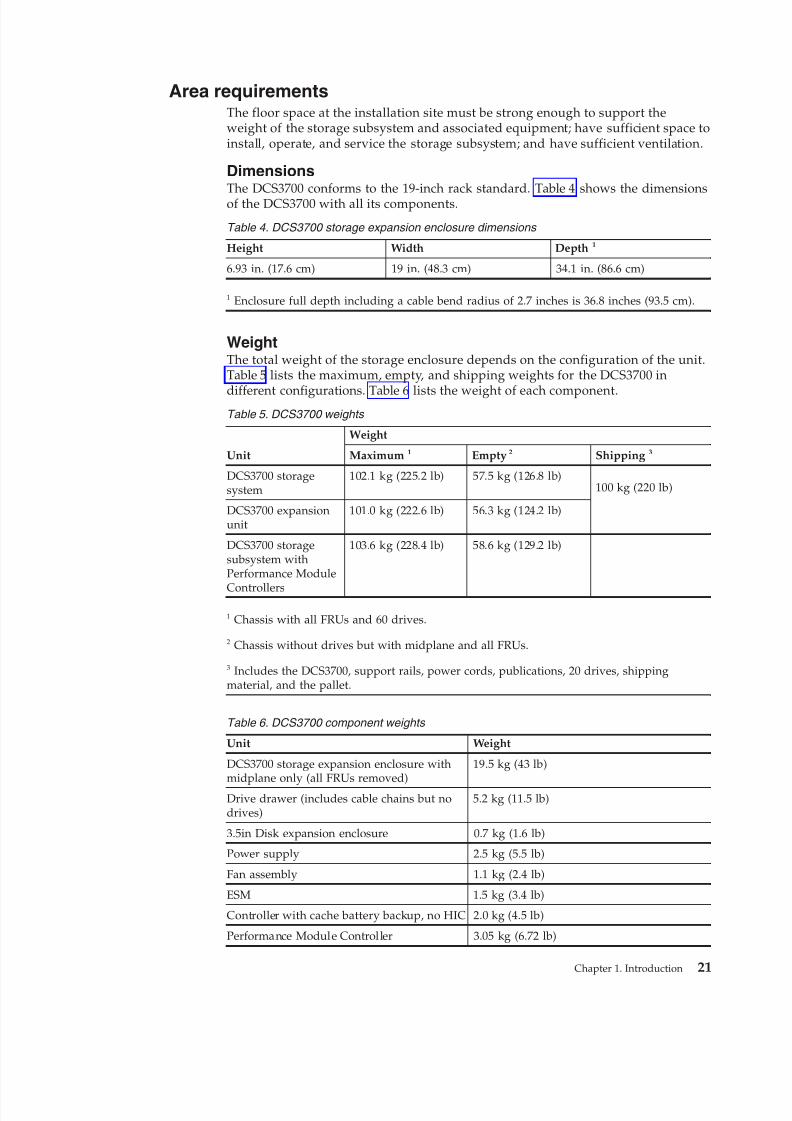
DimensionsThe DCS3700 conforms to the 19-inch rack standard. Table 4 shows the dimensionsof the DCS3700 with all its components.
Table 4. DCS3700 storage expansion enclosure dimensions
Height Width Depth 1
6.93 in. (17.6 cm) 19 in. (48.3 cm) 34.1 in. (86.6 cm)
1 Enclosure full depth including a cable bend radius of 2.7 inches is 36.8 inches (93.5 cm).
WeightThe total weight of the storage enclosure depends on the configuration of the unit.Table 5 lists the maximum, empty, and shipping weights for the DCS3700 in
different configurations. Table 6 lists the weight of each component.Table 5. DCS3700 weights
Unit
Weight
Maximum 1 Empty 2 Shipping 3
DCS3700 storagesystem
102.1 kg (225.2 lb) 57.5 kg (126.8 lb)100 kg (220 lb)
DCS3700 expansionunit
101.0 kg (222.6 lb) 56.3 kg (124.2 lb)
DCS3700 storagesubsystem withPerformance Module
Controllers
103.6 kg (228.4 lb) 58.6 kg (129.2 lb)
1 Chassis with all FRUs and 60 drives.
2 Chassis without drives but with midplane and all FRUs.
3 Includes the DCS3700, support rails, power cords, publications, 20 drives, shippingmaterial, and the pallet.
Table 6. DCS3700 component weights
Unit Weight
DCS3700 storage expansion enclosure withmidplane only (all FRUs removed)
19.5 kg (43 lb)
Drive drawer (includes cable chains but nodrives)
5.2 kg (11.5 lb)
3.5in Disk expansion enclosure 0.7 kg (1.6 lb)
Power supply 2.5 kg (5.5 lb)
Fan assembly 1.1 kg (2.4 lb)
ESM 1.5 kg (3.4 lb)
Controller with cache battery backup, no HIC 2.0 kg (4.5 lb)
Performance Module Controller 3.05 kg (6.72 lb)
Chapter 1. Introduction 21
8/9/2019 Installation, User's, And Maintenance
http://slidepdf.com/reader/full/installation-users-and-maintenance 40/262
Shipping dimensionsThe DCS3700 is shipped on a pallet. Table 7 lists shipping carton dimensions.
Table 7. DCS3700 shipping carton dimensions
Width Depth Height1
24 in. (61 cm) 39.75 in. (101 cm) 29.5 in. (74.9 cm)
1 The height shown includes the height of the pallet.
Environmental requirements and specificationsThis section contains information about the environmental requirements andspecifications for the storage expansion enclosure.
It includes temperature and humidity, altitude, airflow and heat dissipation, shockand vibration requirements, and acoustic noise levels.
Temperature and humidityTable 8 lists the acceptable temperature and humidity ranges for the DCS3700storage expansion enclosure when in storage or in transit.
Note: Substantial deviations from the suggested operating range, in eitherdirection, if sustained for extended periods of time, expose the unit to greater riskof failure from external causes.
Table 8. Temperature and humidity requirements for storage expansion enclosure when in
storage or in transit
Condition Parameter Requirement
Temperature Operating range 10° - 35° C (50° - 95° F)
Maximum rate of change 10° C (18° F) per hourStorage range -10° - 65° C (14° - 149° F)
Maximum rate of change 15° C (27° F) per hour
Transit range -40° C to 65° C (-40° F to 149°F)
Maximum rate of change 20° C (36° F) per hour
Relative humidity (nocondensation)
Operating range 20% to 80%
Storage range 10% to 90%
Transit range 5% to 95%
Maximum dew point 26° C (79° F)
Maximum gradient 10% per hour
AltitudeTable 9 lists the acceptable altitudes for operating, storing, and shipping theDCS3700.
Table 9. DCS3700 altitude ranges
Environment Altitude
Operating 30.5 m (100 ft.) below sea level to 3000 m(9,840 ft) above sea level
22 IBM System Storage DCS3700 Storage Subsystem: Installation, User's, and Maintenance Guide
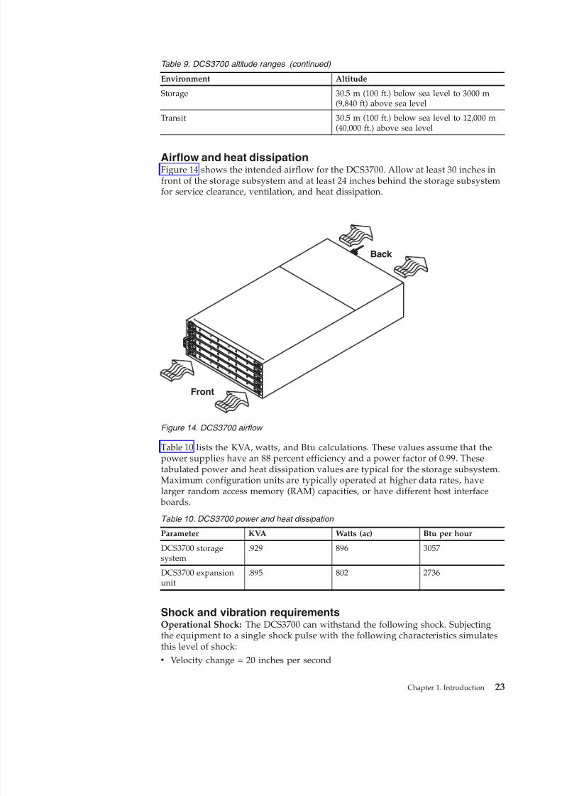
8/9/2019 Installation, User's, And Maintenance
http://slidepdf.com/reader/full/installation-users-and-maintenance 41/262
Table 9. DCS3700 altitude ranges (continued)
Environment Altitude
Storage 30.5 m (100 ft.) below sea level to 3000 m(9,840 ft) above sea level
Transit 30.5 m (100 ft.) below sea level to 12,000 m(40,000 ft.) above sea level
Airflow and heat dissipationFigure 14 shows the intended airflow for the DCS3700. Allow at least 30 inches infront of the storage subsystem and at least 24 inches behind the storage subsystemfor service clearance, ventilation, and heat dissipation.
Table 10 lists the KVA, watts, and Btu calculations. These values assume that thepower supplies have an 88 percent efficiency and a power factor of 0.99. Thesetabulated power and heat dissipation values are typical for the storage subsystem.Maximum configuration units are typically operated at higher data rates, havelarger random access memory (RAM) capacities, or have different host interface
boards.
Table 10. DCS3700 power and heat dissipation
Parameter KVA Watts (ac) Btu per hour
DCS3700 storage
system
.929 896 3057
DCS3700 expansionunit
.895 802 2736
Shock and vibration requirementsOperational Shock: The DCS3700 can withstand the following shock. Subjectingthe equipment to a single shock pulse with the following characteristics simulatesthis level of shock:v Velocity change = 20 inches per second
Front
Back
Figure 14. DCS3700 airflow
Chapter 1. Introduction 23
8/9/2019 Installation, User's, And Maintenance
http://slidepdf.com/reader/full/installation-users-and-maintenance 42/262
v Wave form = 1/2 Sine, 10 g @5ms
Operational Vibration (Random): While in its normal operating position, theDCS3700 continues operating when subjected to a random vibration test using thecriteria shown in Table 11. This test uses the indicated spectral power density for30 minutes in each of the three axes.
Table 11. Random vibration power spectral density Hz 5 17 150 200 500
g2/Hz 9.0x10⁻⁵ 3.0x10⁻⁴ 3.0x10⁻⁴ 9.0x10⁻⁵ 9.0x10⁻⁵
Acoustic noiseTable 12 lists the maximum sound levels emitted by the storage subsystem.
Table 12. DCS3700 sound levels
Measurement Level
Sound power (normal operation) 7.0 bels
Sound power (normal operation with 4 TB
drives)
7.2 bels
These levels are measured in controlled acoustical environments according to ISO7779 and are reported in accordance with ISO 9296. The declared sound powerlevels indicate an upper limit, below which a large portion of machines operate.Sound pressure levels in your location might exceed the average 1-meter valuesstated because of room reflections and other nearby noise. See “Noise” on page 220to know more about measures needed to ensure hearing protection of theoperating personnel.
Electrical requirementsThis section provides information regarding site power and wiring, storagesubsystem ac power requirements, and power cord routing instructions.
Consider the following factors when preparing the installation site:v Protective ground – Site wiring must include a protective ground connection to
the ac power source.
Note: Protective ground is also known as safety ground or chassis ground.v Circuit overloading – Power circuits and associated circuit breakers must
provide sufficient power and overload protection. To prevent possible damage tothe unit, isolate its power source from large switching loads (such as airconditioning motors, elevator motors, and factory loads).
v Power failures – If power fails, the unit automatically performs a power-uprecovery sequence without operator intervention after power is restored.
Attention: The DCS3700 does not support 90-136V AC sources. It supports200-240 V ac sources only. Ensure that the ac input is appropriate for the DCS3700
before turning on the power switches.
Table 13. DCS3700 ac power requirements
AC Power Requirements Range
Nominal Voltage 180 - 264 VAC
24 IBM System Storage DCS3700 Storage Subsystem: Installation, User's, and Maintenance Guide
8/9/2019 Installation, User's, And Maintenance
http://slidepdf.com/reader/full/installation-users-and-maintenance 43/262
Table 13. DCS3700 ac power requirements (continued)
AC Power Requirements Range
Frequency (Hertz) 50 - 60 Hz
Idle Current 4.27 Aa,b
Maximum Operating Current 4.10 Aa
Maximum Surge Current 7.82 Aa
a. Typical voltage: 220 V AC, 50 Hz
b. While the system is idle, it still performs background data scrubbing on all the drives.However, during regular I/O the system benefits from cache, which uses less power.
Note: The DCS3700 power supplies have C20 power inlets.
Power and site wiring requirements for models with powersupply and fan unitsThe storage expansion enclosure uses wide-ranging redundant power supplies that
automatically accommodate voltages to the power source. The power suppliesoperate within the ranges specified in Table 13 on page 24. The power suppliesmeet standard voltage requirements for both domestic (inside USA) andinternational (outside USA) operations. They use standard industrial wiring withline-to-neutral or line-to-line power connections.
The agency voltage and current ratings for the DCS3700 storage expansionenclosure are 200 VAC - 240 VAC and 7.56 A - 6.30 A.
Power recovery after a power failure: After normal power is restored, the storageexpansion enclosure performs power-up recovery procedures automaticallywithout operator intervention.
Power cords and receptacles: The DCS3700 ships with either two IEC C19 to C14 jumper cords or two IEC C19 to C20 jumper cords. The C19 plug connects to theDCS3700 power supply and the other end is used to connect to the rack PDUoutlets. It is not shipped with the power cords that can be used to connect itdirectly to an electrical outlet in the destination country. You must purchase thepower cords that are appropriate for use in a typical outlet in the destinationcountry. See Chapter 10, “Power cords,” on page 211 for more information.
Heat output, airflow, and coolingThe subsystem has a hot aisle and cold aisle requirement for disk subsystemreliability.
See “Airflow and heat dissipation” on page 23 for heat output, airflow, and coolingspecifications.
Note: In general, disk subsystem reliability tends to decrease as the ambienttemperature of the environment in which it is being used increases.
When racks that contain many storage expansion enclosures are to be installedtogether, the following requirements must be met to ensure that the storageexpansion enclosures are adequately cooled:v Air enters at the front of the rack and leaves at the back. To prevent the air that
is leaving the rack from entering the intake of another piece of equipment, you
Chapter 1. Introduction 25

8/9/2019 Installation, User's, And Maintenance
http://slidepdf.com/reader/full/installation-users-and-maintenance 44/262
must position the racks in alternate rows, back-to-back, and front-to-front. Thisarrangement is known as cold aisle and hot aisle and is shown in Figure 15.
v Where racks are in rows, each rack must touch the rack that is next to it toreduce the amount of hot air that can flow around from the back of the rack intothe intakes of the storage expansion enclosures that are in that rack. You mustuse Suite Attach Kits to completely seal any gaps that remain between the racks.For details about Suite Attach Kits, contact your marketing representative.
v Where racks are in rows front-to-front or back-to-back, a gap of at least 1220 mm(48 in.) must separate the rows across the cold aisle.
v To ensure correct airflow in each rack, the rack filler plates must be installed inunused positions. Also, all the gaps in the front of the racks must be sealed,including the gaps between the storage expansion enclosures.
1220 mm coldaisle width
2440 mm betweencenter lines of hotand cold aisle
Perforated tilesor gratings
back
back
T42 racks
T42 racks
T42 racks
Cold aisle
Hot aisle
A i r
c o n
d i t i o
n e r
back
front
front
front
Airflow
Figure 15. Example of cold aisle/hot aisle rack configuration
26 IBM System Storage DCS3700 Storage Subsystem: Installation, User's, and Maintenance Guide
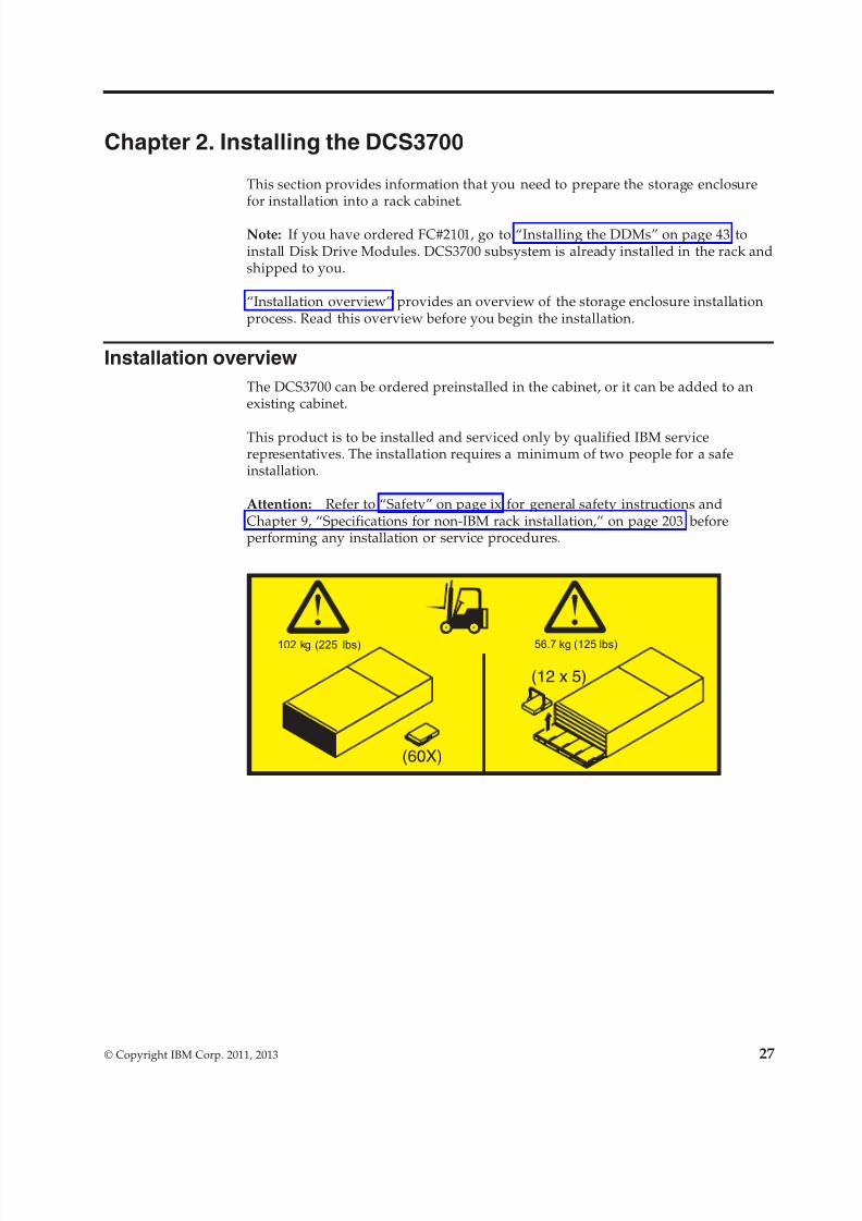
8/9/2019 Installation, User's, And Maintenance
http://slidepdf.com/reader/full/installation-users-and-maintenance 45/262
Chapter 2. Installing the DCS3700
This section provides information that you need to prepare the storage enclosurefor installation into a rack cabinet.
Note: If you have ordered FC#2101, go to “Installing the DDMs” on page 43 toinstall Disk Drive Modules. DCS3700 subsystem is already installed in the rack andshipped to you.
“Installation overview” provides an overview of the storage enclosure installationprocess. Read this overview before you begin the installation.
Installation overview
The DCS3700 can be ordered preinstalled in the cabinet, or it can be added to anexisting cabinet.
This product is to be installed and serviced only by qualified IBM servicerepresentatives. The installation requires a minimum of two people for a safeinstallation.
Attention: Refer to “Safety” on page ix for general safety instructions andChapter 9, “Specifications for non-IBM rack installation,” on page 203 beforeperforming any installation or service procedures.
56.7 kg (125 lbs)102 kg (225 lbs)
(12 x 5)
(60X)
© Copyright IBM Corp. 2011, 2013 27
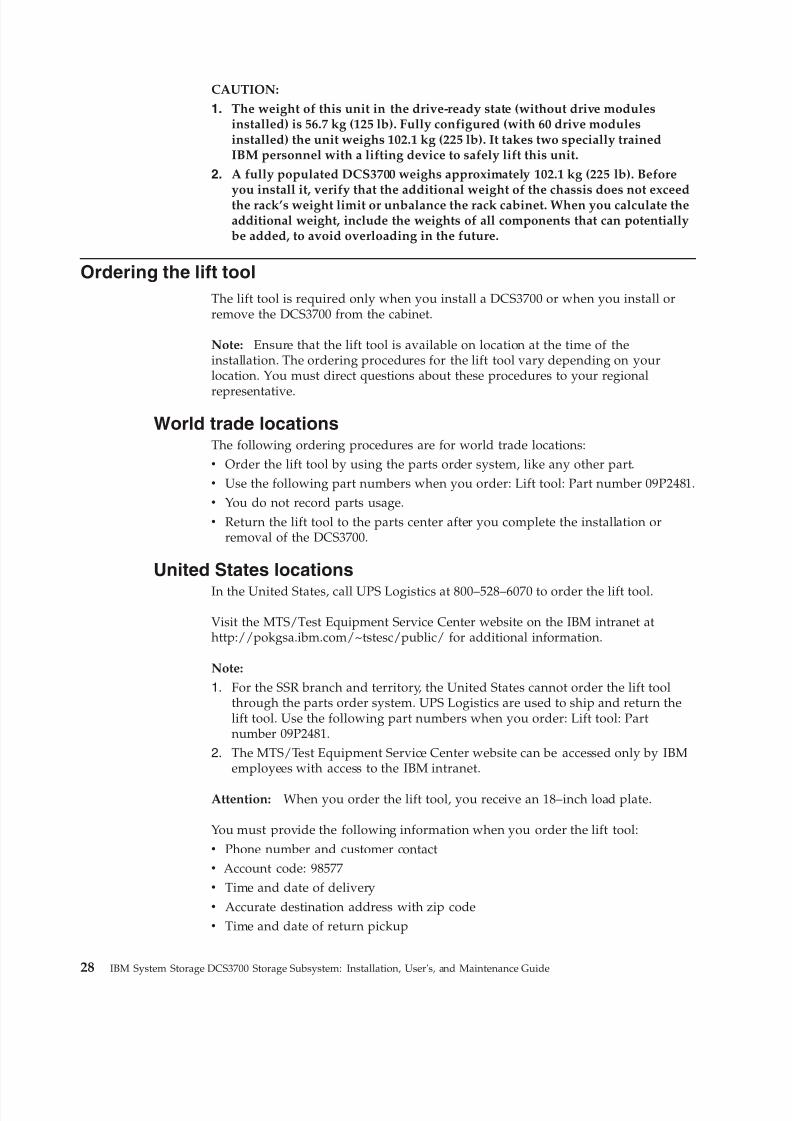
8/9/2019 Installation, User's, And Maintenance
http://slidepdf.com/reader/full/installation-users-and-maintenance 46/262
CAUTION:
1. The weight of this unit in the drive-ready state (without drive modulesinstalled) is 56.7 kg (125 lb). Fully configured (with 60 drive modulesinstalled) the unit weighs 102.1 kg (225 lb). It takes two specially trainedIBM personnel with a lifting device to safely lift this unit.
2. A fully populated DCS3700 weighs approximately 102.1 kg (225 lb). Before
you install it, verify that the additional weight of the chassis does not exceedthe rack’s weight limit or unbalance the rack cabinet. When you calculate theadditional weight, include the weights of all components that can potentiallybe added, to avoid overloading in the future.
Ordering the lift tool
The lift tool is required only when you install a DCS3700 or when you install orremove the DCS3700 from the cabinet.
Note: Ensure that the lift tool is available on location at the time of theinstallation. The ordering procedures for the lift tool vary depending on yourlocation. You must direct questions about these procedures to your regional
representative.
World trade locationsThe following ordering procedures are for world trade locations:v Order the lift tool by using the parts order system, like any other part.v Use the following part numbers when you order: Lift tool: Part number 09P2481.v You do not record parts usage.v Return the lift tool to the parts center after you complete the installation or
removal of the DCS3700.
United States locations
In the United States, call UPS Logistics at 800–528–6070 to order the lift tool.
Visit the MTS/Test Equipment Service Center website on the IBM intranet athttp://pokgsa.ibm.com/~tstesc/public/ for additional information.
Note:
1. For the SSR branch and territory, the United States cannot order the lift toolthrough the parts order system. UPS Logistics are used to ship and return thelift tool. Use the following part numbers when you order: Lift tool: Partnumber 09P2481.
2. The MTS/Test Equipment Service Center website can be accessed only by IBMemployees with access to the IBM intranet.
Attention: When you order the lift tool, you receive an 18–inch load plate.
You must provide the following information when you order the lift tool:v Phone number and customer contactv Account code: 98577v Time and date of deliveryv Accurate destination address with zip codev Time and date of return pickup
28 IBM System Storage DCS3700 Storage Subsystem: Installation, User's, and Maintenance Guide
8/9/2019 Installation, User's, And Maintenance
http://slidepdf.com/reader/full/installation-users-and-maintenance 47/262
Failure to provide this information might delay the completion of the order requestand the shipping request. You must return the lift tool at the time that wasscheduled with UPS Logistics. If you need to change the scheduled return time ordate, contact UPS Logistics. You are responsible for ensuring that all of thepaperwork and components are packed and restored in the lift tool shippingcontainer. Ensure that the lift tool is functioning properly before you release thetool to UPS Logistics for return. You are accountable for the lift tool until UPS
Logistics picks up the lift tool for return delivery to their parts storage facility.Contact your branch office tools coordinator or your region specialist if you haveany questions or concerns.
Installation sequence
The following sequence summarizes the installation steps:
1. Prepare the installation site and the rack cabinet.
2. Unpack the DCS3700 and other hardware from the shipping box. See“Preparing for installation” on page 30.
Attention:a. Because of the size and weight of the storage enclosure as shipped, you
require a lift tool and two trained service technicians to push the enclosureout of its custom-designed package and onto the lift tool. If a lift tool isnot available, see Chapter 11, “Component weights,” on page 215 foradditional information.
b. Before you move or relocate a rack that contains DCS3700 storageenclosures, see “Relocating the DCS3700” on page 74 for additionalinformation.
Note: For more information about how to use a lift tool, see thedocumentation that came with the lift tool.
3. Install the support rails in the rack. See “Installing the support rails” on page35.
4. Install the DCS3700 storage enclosure in the rack. See “Installing the DCS3700into a rack” on page 41.
5. Install disk drives in the DCS3700 storage enclosure. See “Installing theDDMs” on page 43.
6. If there are other DCS3700 storage enclosures to be installed in the same rack,repeat step 3 to step 5 for the other DCS3700 units.
56.7 kg (125 lbs)102 kg (225 lbs)
(12 x 5)
(60X)
Chapter 2. Installing the DCS3700 29
8/9/2019 Installation, User's, And Maintenance
http://slidepdf.com/reader/full/installation-users-and-maintenance 48/262
7. Install the power supply cables to the DCS3700s. Make sure that the DCS3700power supplies are connected to 240 V AC sources only. See “Cabling thepower supply” on page 73.
8. Cable the DCS3700 Storage system to any storage expansion enclosures. SeeChapter 3, “Cabling the DCS3700 storage system,” on page 47.
9. Install the DS Storage Manager host software to manage the DCS3700 Storage
system. See “Software and hardware compatibility and upgrades” on page 18for the appropriate version. For instructions to install the DS Storage Managersoftware, see the IBM System Storage DS Storage Manager Version 10 Installationand Host Support Guide (for DS Storage Manager V10.77 or earlier) or the IBMSystem Storage DS Storage Manager Version 10.8 Installation and Host SupportGuide (for DS Storage Manager V10.83 or later) for the applicable operatingsystem.
10. Turn on the DCS3700 (if you have not done so already). See “Powering on theDCS3700” on page 77.
11. Upgrade the controller firmware. See “Finding Storage Manager software,controller firmware, and README files” on page xvi for more information.
Handling static-sensitive devicesTo reduce the possibility of electrostatic discharge, follow these precautions.
Attention: Static electricity can damage electronic devices and your system. Toavoid damage, keep static-sensitive devices in their static-protective packages untilyou are ready to install them.v Limit your movement, so that it does not cause static electricity to build up
around you.v Handle the device carefully, holding it by its edges or its frame.v Do not touch solder joints, pins, or exposed printed circuitry.v Do not leave the device where others can handle and possibly damage the
device.v While the device is still in its static-protective package, touch it to an unpainted
metal part of the system unit for at least 2 seconds. This drains static electricityfrom the package and from your body.
v Remove the device from its package and install it directly into your system unitwithout setting it down. If it is necessary to set the device down, place it in itsstatic-protective package. Do not place the device on your system unit cover oron a metal table.
v Take additional care when handling devices during cold weather becauseheating reduces indoor humidity and increases static electricity.
Preparing for installation
Complete the following steps to prepare the storage enclosure for installation intoa rack cabinet.
Before installing the storage enclosure, create a detailed plan of how this unit will be used in your storage configuration. The plan should include determining RAIDlevels, failover requirements, operating systems to be used, and total storagecapacity requirements.1. Prepare the site according to the area, environmental, power, and site
requirements. For more information, see “Specifications” on page 20.
30 IBM System Storage DCS3700 Storage Subsystem: Installation, User's, and Maintenance Guide
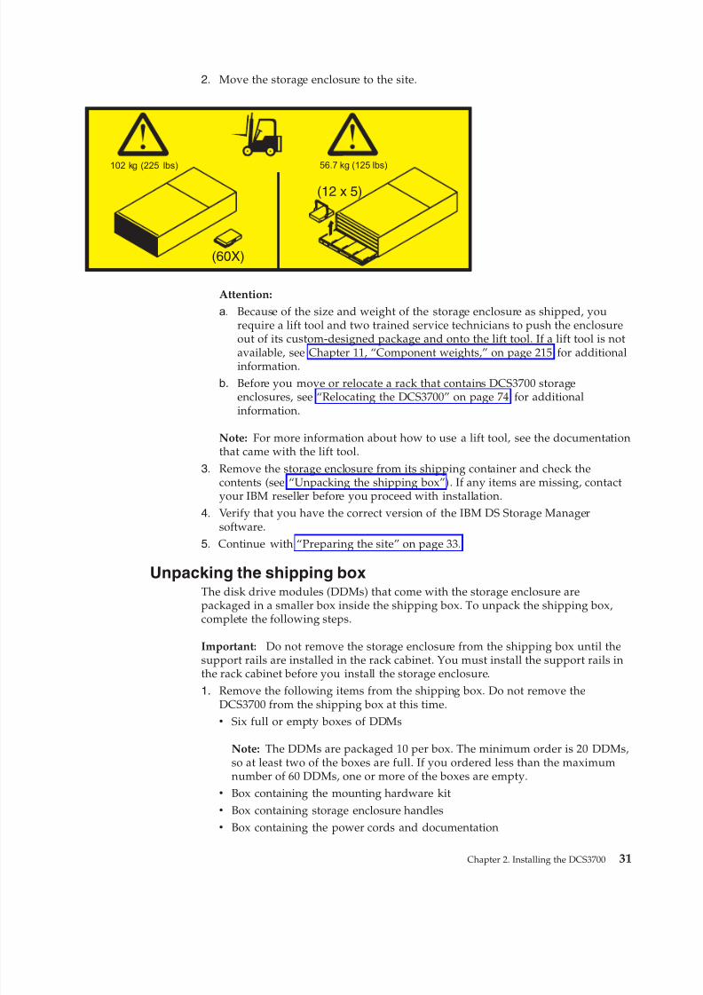
8/9/2019 Installation, User's, And Maintenance
http://slidepdf.com/reader/full/installation-users-and-maintenance 49/262
2. Move the storage enclosure to the site.
Attention:
a. Because of the size and weight of the storage enclosure as shipped, yourequire a lift tool and two trained service technicians to push the enclosureout of its custom-designed package and onto the lift tool. If a lift tool is notavailable, see Chapter 11, “Component weights,” on page 215 for additionalinformation.
b. Before you move or relocate a rack that contains DCS3700 storageenclosures, see “Relocating the DCS3700” on page 74 for additionalinformation.
Note: For more information about how to use a lift tool, see the documentationthat came with the lift tool.
3. Remove the storage enclosure from its shipping container and check thecontents (see “Unpacking the shipping box”). If any items are missing, contactyour IBM reseller before you proceed with installation.
4. Verify that you have the correct version of the IBM DS Storage Managersoftware.
5. Continue with “Preparing the site” on page 33.
Unpacking the shipping boxThe disk drive modules (DDMs) that come with the storage enclosure arepackaged in a smaller box inside the shipping box. To unpack the shipping box,complete the following steps.
Important: Do not remove the storage enclosure from the shipping box until thesupport rails are installed in the rack cabinet. You must install the support rails inthe rack cabinet before you install the storage enclosure.
1. Remove the following items from the shipping box. Do not remove theDCS3700 from the shipping box at this time.
v Six full or empty boxes of DDMs
Note: The DDMs are packaged 10 per box. The minimum order is 20 DDMs,so at least two of the boxes are full. If you ordered less than the maximumnumber of 60 DDMs, one or more of the boxes are empty.
v Box containing the mounting hardware kitv Box containing storage enclosure handlesv Box containing the power cords and documentation
56.7 kg (125 lbs)102 kg (225 lbs)
(12 x 5)
(60X)
Chapter 2. Installing the DCS3700 31
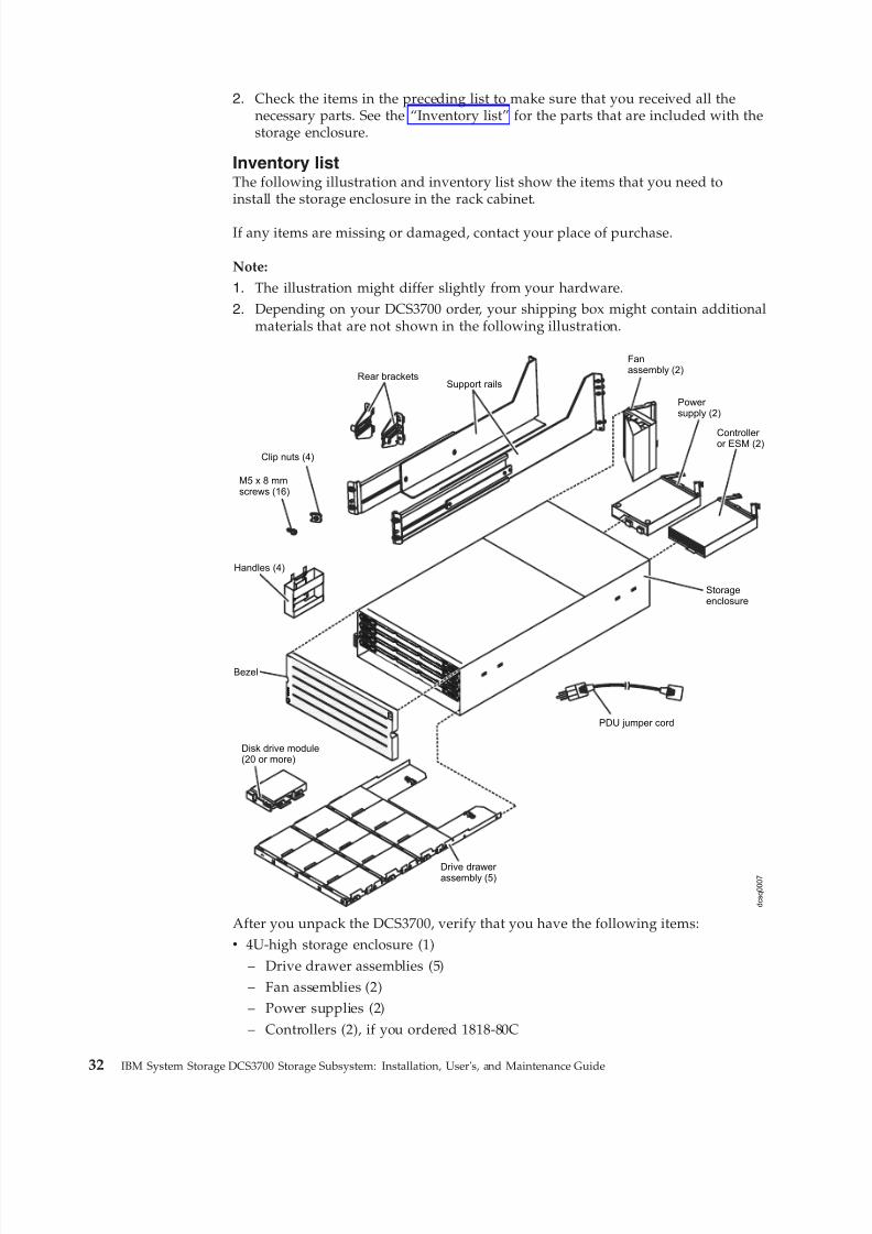
8/9/2019 Installation, User's, And Maintenance
http://slidepdf.com/reader/full/installation-users-and-maintenance 50/262
2. Check the items in the preceding list to make sure that you received all thenecessary parts. See the “Inventory list” for the parts that are included with thestorage enclosure.
Inventory listThe following illustration and inventory list show the items that you need toinstall the storage enclosure in the rack cabinet.
If any items are missing or damaged, contact your place of purchase.
Note:
1. The illustration might differ slightly from your hardware.
2. Depending on your DCS3700 order, your shipping box might contain additionalmaterials that are not shown in the following illustration.
Support rails
Storageenclosure
M5 x 8 mmscrews (16)
PDU jumper cord
Rear brackets
Bezel
Clip nuts (4)
Fanassembly (2)
Power supply (2)
Controller or ESM (2)
Drive drawer assembly (5)
Disk drive module(20 or more)
Handles (4)
d c s q
0 0 0 7
After you unpack the DCS3700, verify that you have the following items:v 4U-high storage enclosure (1)
– Drive drawer assemblies (5)– Fan assemblies (2)– Power supplies (2)– Controllers (2), if you ordered 1818-80C
32 IBM System Storage DCS3700 Storage Subsystem: Installation, User's, and Maintenance Guide
8/9/2019 Installation, User's, And Maintenance
http://slidepdf.com/reader/full/installation-users-and-maintenance 51/262
– ESMs (2), if you ordered 1818-80Ev Handles (4), packaged in a smaller box inside the shipping boxv DDMs (20 or more, depending on your DCS3700 order), packaged in a smaller
box inside the shipping boxv Bezel (1)v Rack-mounting hardware kit (1), packaged in a smaller box inside the shipping
box, including:– Rails (2), right and left assembly– Rear brackets (2)– M5 black hex-head slotted screws (16)
Note: The screws are either preinstalled in the support rails or packaged in aplastic bag.
– Washers (8)– Clip nuts (4)
Important: The DCS3700 does not ship with region-specific ac power cords. You
must obtain the IBM-approved power cords for your region. For more information,see Chapter 10, “Power cords,” on page 211.
ToolsThis is the list of tools you must be ready with before installation.
Before you install the storage enclosure, the installation area must have an internetconnection, and you must have the following tools:v A cart to hold the storage enclosure and its componentsv Labels for the cable connectorsv A medium flat-blade screwdriverv A No. 2 Phillips screwdriver or an M5 hex driver
v Anti-static protection
Tools and hardware requiredGather the tools and equipment you need for installation.
These might include:v A portable mechanized liftv A number 2 Phillips screwdriverv An M5 hex nut driverv A medium flat-blade screwdriverv anti-static protection (such as a grounding wrist strap)v The rack power jumper cords that are shipped with the storage enclosurev LC Fiber Optic and Ethernet interface cables and cable strapsv SFP/SFP+ modulesv Rack-mounting hardware that ships with the storage enclosure
Preparing the siteThis section lists the floor space requirements and weight information for thestorage enclosure.
Chapter 2. Installing the DCS3700 33
8/9/2019 Installation, User's, And Maintenance
http://slidepdf.com/reader/full/installation-users-and-maintenance 52/262
For information about interface cables and connections, see Chapter 3, “Cabling theDCS3700 storage system,” on page 47.
Floor space: The floor area at the installation site must provide the followingconditions:v Enough stability to support the weight of the fully configured storage enclosure
and associated systemsv Sufficient space to install the storage enclosure
Weight: The weight of the storage enclosure depends on the number of components that are installed. A fully configured storage enclosure with twopower supplies, two fan assemblies, two controllers or ESMs, and 60 hard diskdrives weighs up to 228.4 lb (103.6 kg). For more information, see Chapter 11,“Component weights,” on page 215.
Other: Before you prepare the rack:v Install uninterruptible power supply (UPS) devices.v Install host bus adapters (HBAs), switches, or other devices, if applicable.v
Route interface cables from the hosts or switches to the installation area.v Route main power cords to the installation area.
Preparing the rack Before you install the storage enclosure in a rack, keep in mind the followingconsiderations .v When DCS3700 enclosures are to be plant or field integrated into the IBM racks,
the rack must be configured with PDU power cords rated for 240 volt electricalservice.
v IBM does not support the ruggedized rack feature for the 2101-200 rack when itis used with the DCS3700. The DCS3700 does not fit in the 2101-200 rack if theruggedized rack feature is installed.
v Do not install the DCS3700 above EIA Unit position 32 in any rack. Installing theDCS3700 above U position 32 requires a ladder and is not supported.
v If you are using a non-IBM rack or cabinet, review the information in Chapter 9,“Specifications for non-IBM rack installation,” on page 203.
v Do not extend more than one device out of the rack cabinet at the same time.v To ensure proper airflow, do not block the air vents; 15 cm (6 in.) of air space is
sufficient.v To ensure rack stability, load the rack starting at the bottom.v If you install multiple components in the rack, do not overload the power
outlets.v Always connect the storage enclosure to a properly grounded outlet.
Complete the following steps to prepare the rack before you install the storageenclosure:1. Move, unpack, and level the rack at the installation site (if needed).
2. Remove the external rack panels.3. If necessary, stop all I/O activity to the devices in the rack.4. If necessary, turn off all drive enclosure and rack power. Disconnect existing
power, network, and other external cables.
5. Install any additional interface cables and power cables.
34 IBM System Storage DCS3700 Storage Subsystem: Installation, User's, and Maintenance Guide
8/9/2019 Installation, User's, And Maintenance
http://slidepdf.com/reader/full/installation-users-and-maintenance 53/262
After you have completed these steps, continue with “Installing the support rails.”
Installing the support rails
This is the procedure to install the support rails in the cabinet before installing theDCS3700 subsystem.
Note: Duplicate copies of the rack mounting templates are provided in Chapter 8,“Rack mounting template,” on page 199. If you want to tear out the templatesfrom this document for easier use, use the copies in Chapter 8, “Rack mountingtemplate,” on page 199 rather than the copies provided in this section.
Use the following templates (Figure 16 on page 36 and Figure 17 on page 37) toidentify the proper locations for inserting M5 screws when mounting the supportrails and DCS3700 to a rack. The locations for the M5 screws are highlighted in thetemplates.
The DCS3700 is 4U high. Align the template with the rack at a U boundary. U boundaries are shown as horizontal dashed lines in the rack mounting templates.
Note: The mounting holes that are shown in the following templates are round.The holes in the rack might be round, square, or threaded.
Chapter 2. Installing the DCS3700 35

8/9/2019 Installation, User's, And Maintenance
http://slidepdf.com/reader/full/installation-users-and-maintenance 54/262
3U3U
2U 2U
1U 1U
0U 0U
Rail assembly(front left)
Rail assembly(front right)
FRONT
Rack MountingTemplate
4U4U
Install second
Install first
Install second
Install first
Install first Install first
Install second Install second
Figure 16. Front rack mounting template
36 IBM System Storage DCS3700 Storage Subsystem: Installation, User's, and Maintenance Guide
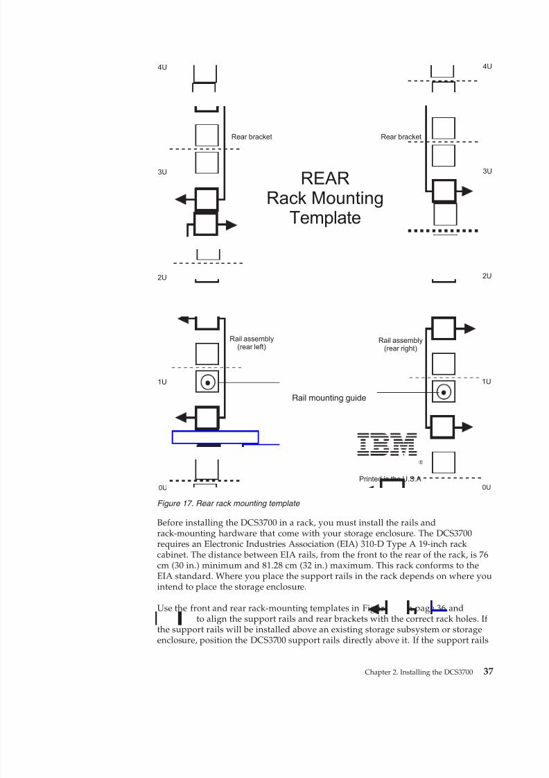
8/9/2019 Installation, User's, And Maintenance
http://slidepdf.com/reader/full/installation-users-and-maintenance 55/262
Before installing the DCS3700 in a rack, you must install the rails andrack-mounting hardware that come with your storage enclosure. The DCS3700
requires an Electronic Industries Association (EIA) 310-D Type A 19-inch rackcabinet. The distance between EIA rails, from the front to the rear of the rack, is 76cm (30 in.) minimum and 81.28 cm (32 in.) maximum. This rack conforms to theEIA standard. Where you place the support rails in the rack depends on where youintend to place the storage enclosure.
Use the front and rear rack-mounting templates in Figure 16 on page 36 andFigure 17 to align the support rails and rear brackets with the correct rack holes. If the support rails will be installed above an existing storage subsystem or storageenclosure, position the DCS3700 support rails directly above it. If the support rails
®
3U3U
2U 2U
1U 1U
0U 0U
Rail assembly(rear left)
Rail assembly(rear right)
Printed in the U.S.A
REARRack Mounting
Template
Rail mounting guide
4U4U
Rear bracket Rear bracket
Figure 17. Rear rack mounting template
Chapter 2. Installing the DCS3700 37
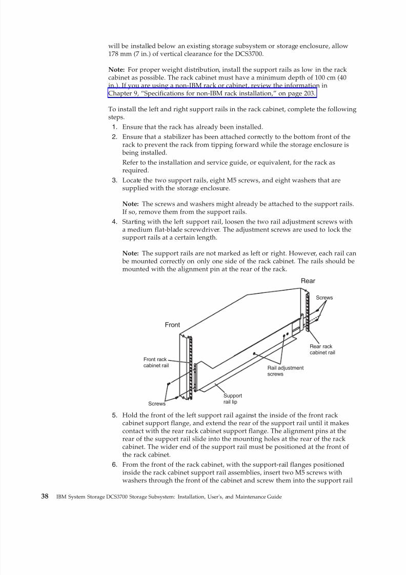
8/9/2019 Installation, User's, And Maintenance
http://slidepdf.com/reader/full/installation-users-and-maintenance 56/262
will be installed below an existing storage subsystem or storage enclosure, allow178 mm (7 in.) of vertical clearance for the DCS3700.
Note: For proper weight distribution, install the support rails as low in the rackcabinet as possible. The rack cabinet must have a minimum depth of 100 cm (40in.). If you are using a non-IBM rack or cabinet, review the information inChapter 9, “Specifications for non-IBM rack installation,” on page 203.
To install the left and right support rails in the rack cabinet, complete the followingsteps.1. Ensure that the rack has already been installed.
2. Ensure that a stabilizer has been attached correctly to the bottom front of therack to prevent the rack from tipping forward while the storage enclosure is
being installed.Refer to the installation and service guide, or equivalent, for the rack asrequired.
3. Locate the two support rails, eight M5 screws, and eight washers that aresupplied with the storage enclosure.
Note: The screws and washers might already be attached to the support rails.If so, remove them from the support rails.
4. Starting with the left support rail, loosen the two rail adjustment screws witha medium flat-blade screwdriver. The adjustment screws are used to lock thesupport rails at a certain length.
Note: The support rails are not marked as left or right. However, each rail can be mounted correctly on only one side of the rack cabinet. The rails should bemounted with the alignment pin at the rear of the rack.
Front
Rear
Front rackcabinet rail
Screws
Support
rail lip
Rail adjustmentscrews
Rear rackcabinet rail
Screws
5. Hold the front of the left support rail against the inside of the front rackcabinet support flange, and extend the rear of the support rail until it makescontact with the rear rack cabinet support flange. The alignment pins at therear of the support rail slide into the mounting holes at the rear of the rackcabinet. The wider end of the support rail must be positioned at the front of the rack cabinet.
6. From the front of the rack cabinet, with the support-rail flanges positionedinside the rack cabinet support rail assemblies, insert two M5 screws withwashers through the front of the cabinet and screw them into the support rail
38 IBM System Storage DCS3700 Storage Subsystem: Installation, User's, and Maintenance Guide
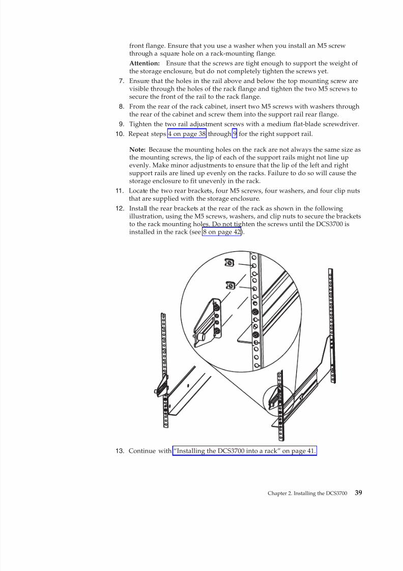
8/9/2019 Installation, User's, And Maintenance
http://slidepdf.com/reader/full/installation-users-and-maintenance 57/262
front flange. Ensure that you use a washer when you install an M5 screwthrough a square hole on a rack-mounting flange.Attention: Ensure that the screws are tight enough to support the weight of the storage enclosure, but do not completely tighten the screws yet.
7. Ensure that the holes in the rail above and below the top mounting screw arevisible through the holes of the rack flange and tighten the two M5 screws to
secure the front of the rail to the rack flange.8. From the rear of the rack cabinet, insert two M5 screws with washers throughthe rear of the cabinet and screw them into the support rail rear flange.
9. Tighten the two rail adjustment screws with a medium flat-blade screwdriver.
10. Repeat steps 4 on page 38 through 9 for the right support rail.
Note: Because the mounting holes on the rack are not always the same size asthe mounting screws, the lip of each of the support rails might not line upevenly. Make minor adjustments to ensure that the lip of the left and rightsupport rails are lined up evenly on the racks. Failure to do so will cause thestorage enclosure to fit unevenly in the rack.
11. Locate the two rear brackets, four M5 screws, four washers, and four clip nuts
that are supplied with the storage enclosure.12. Install the rear brackets at the rear of the rack as shown in the following
illustration, using the M5 screws, washers, and clip nuts to secure the bracketsto the rack mounting holes. Do not tighten the screws until the DCS3700 isinstalled in the rack (see 8 on page 42).
13. Continue with “Installing the DCS3700 into a rack” on page 41.
Chapter 2. Installing the DCS3700 39
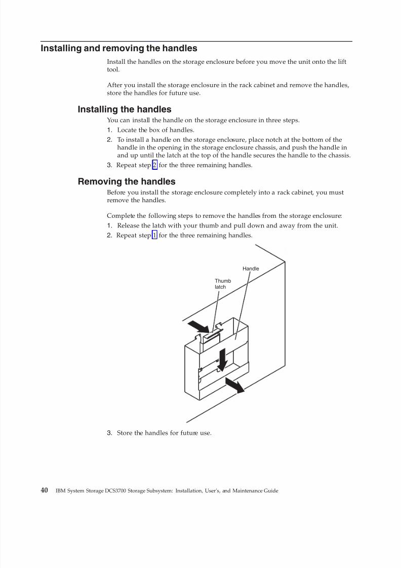
8/9/2019 Installation, User's, And Maintenance
http://slidepdf.com/reader/full/installation-users-and-maintenance 58/262
Installing and removing the handles
Install the handles on the storage enclosure before you move the unit onto the lifttool.
After you install the storage enclosure in the rack cabinet and remove the handles,store the handles for future use.
Installing the handlesYou can install the handle on the storage enclosure in three steps.
1. Locate the box of handles.2. To install a handle on the storage enclosure, place notch at the bottom of the
handle in the opening in the storage enclosure chassis, and push the handle inand up until the latch at the top of the handle secures the handle to the chassis.
3. Repeat step 2 for the three remaining handles.
Removing the handlesBefore you install the storage enclosure completely into a rack cabinet, you must
remove the handles.
Complete the following steps to remove the handles from the storage enclosure:
1. Release the latch with your thumb and pull down and away from the unit.2. Repeat step 1 for the three remaining handles.
Thumblatch
Handle
3. Store the handles for future use.
40 IBM System Storage DCS3700 Storage Subsystem: Installation, User's, and Maintenance Guide
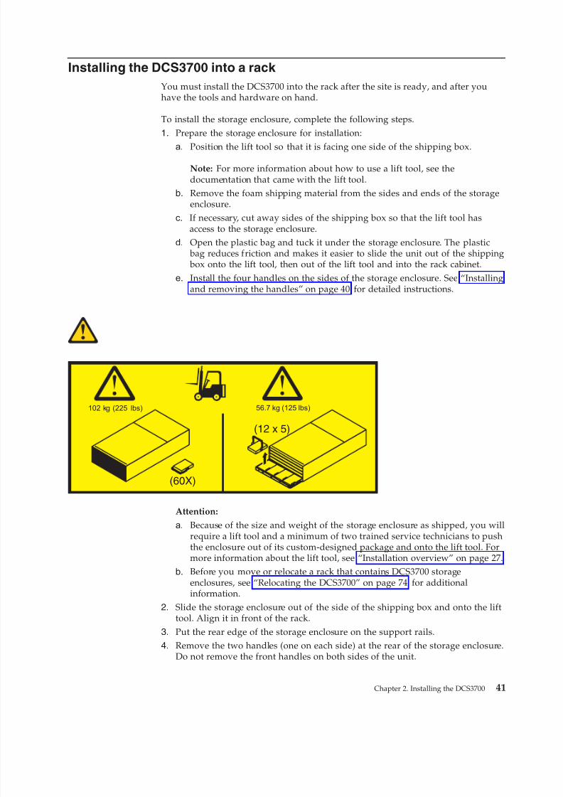
8/9/2019 Installation, User's, And Maintenance
http://slidepdf.com/reader/full/installation-users-and-maintenance 59/262
Installing the DCS3700 into a rack
You must install the DCS3700 into the rack after the site is ready, and after youhave the tools and hardware on hand.
To install the storage enclosure, complete the following steps.
1. Prepare the storage enclosure for installation:a. Position the lift tool so that it is facing one side of the shipping box.
Note: For more information about how to use a lift tool, see thedocumentation that came with the lift tool.
b. Remove the foam shipping material from the sides and ends of the storageenclosure.
c. If necessary, cut away sides of the shipping box so that the lift tool hasaccess to the storage enclosure.
d. Open the plastic bag and tuck it under the storage enclosure. The plastic bag reduces friction and makes it easier to slide the unit out of the shipping box onto the lift tool, then out of the lift tool and into the rack cabinet.
e. Install the four handles on the sides of the storage enclosure. See “Installingand removing the handles” on page 40 for detailed instructions.
Attention:
a. Because of the size and weight of the storage enclosure as shipped, you willrequire a lift tool and a minimum of two trained service technicians to pushthe enclosure out of its custom-designed package and onto the lift tool. For
more information about the lift tool, see “Installation overview” on page 27.b. Before you move or relocate a rack that contains DCS3700 storage
enclosures, see “Relocating the DCS3700” on page 74 for additionalinformation.
2. Slide the storage enclosure out of the side of the shipping box and onto the lifttool. Align it in front of the rack.
3. Put the rear edge of the storage enclosure on the support rails.4. Remove the two handles (one on each side) at the rear of the storage enclosure.
Do not remove the front handles on both sides of the unit.
56.7 kg (125 lbs)102 kg (225 lbs)
(12 x 5)
(60X)
Chapter 2. Installing the DCS3700 41
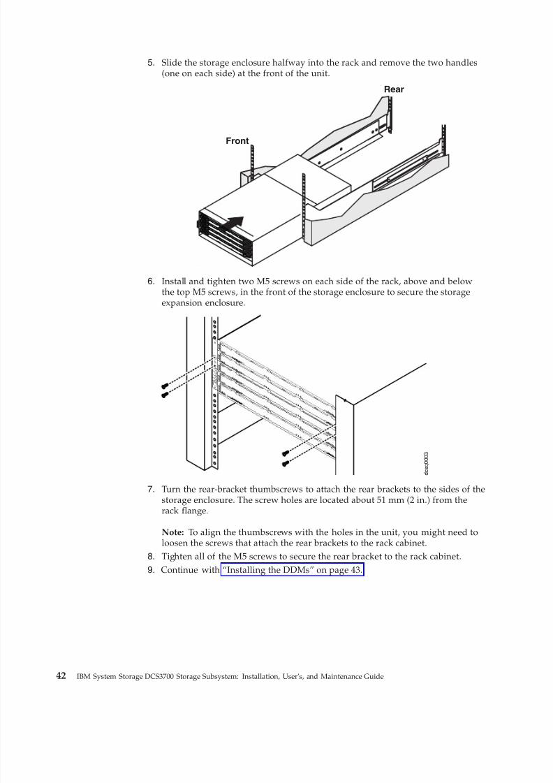
8/9/2019 Installation, User's, And Maintenance
http://slidepdf.com/reader/full/installation-users-and-maintenance 60/262
5. Slide the storage enclosure halfway into the rack and remove the two handles(one on each side) at the front of the unit.
Front
Rear
6. Install and tighten two M5 screws on each side of the rack, above and belowthe top M5 screws, in the front of the storage enclosure to secure the storageexpansion enclosure.
d c s q 0 0 0 3
7. Turn the rear-bracket thumbscrews to attach the rear brackets to the sides of thestorage enclosure. The screw holes are located about 51 mm (2 in.) from therack flange.
Note: To align the thumbscrews with the holes in the unit, you might need toloosen the screws that attach the rear brackets to the rack cabinet.
8. Tighten all of the M5 screws to secure the rear bracket to the rack cabinet.
9. Continue with “Installing the DDMs” on page 43.
42 IBM System Storage DCS3700 Storage Subsystem: Installation, User's, and Maintenance Guide
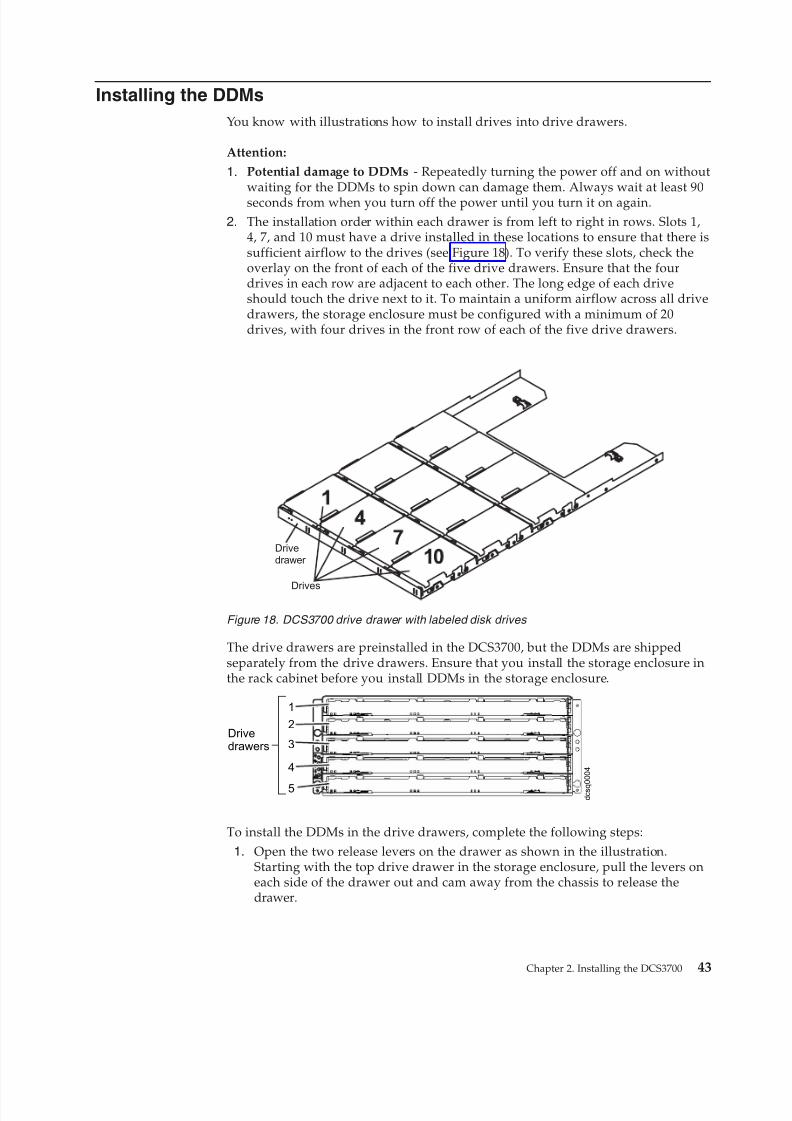
8/9/2019 Installation, User's, And Maintenance
http://slidepdf.com/reader/full/installation-users-and-maintenance 61/262
Installing the DDMs
You know with illustrations how to install drives into drive drawers.
Attention:
1. Potential damage to DDMs - Repeatedly turning the power off and on withoutwaiting for the DDMs to spin down can damage them. Always wait at least 90seconds from when you turn off the power until you turn it on again.
2. The installation order within each drawer is from left to right in rows. Slots 1,4, 7, and 10 must have a drive installed in these locations to ensure that there issufficient airflow to the drives (see Figure 18). To verify these slots, check theoverlay on the front of each of the five drive drawers. Ensure that the fourdrives in each row are adjacent to each other. The long edge of each driveshould touch the drive next to it. To maintain a uniform airflow across all drivedrawers, the storage enclosure must be configured with a minimum of 20drives, with four drives in the front row of each of the five drive drawers.
The drive drawers are preinstalled in the DCS3700, but the DDMs are shippedseparately from the drive drawers. Ensure that you install the storage enclosure inthe rack cabinet before you install DDMs in the storage enclosure.
Drivedrawers
1
2
3
4
5 d c s q 0 0 0 4
To install the DDMs in the drive drawers, complete the following steps:
1. Open the two release levers on the drawer as shown in the illustration.Starting with the top drive drawer in the storage enclosure, pull the levers oneach side of the drawer out and cam away from the chassis to release thedrawer.
Drivedrawer
Drives
Figure 18. DCS3700 drive drawer with labeled disk drives
Chapter 2. Installing the DCS3700 43
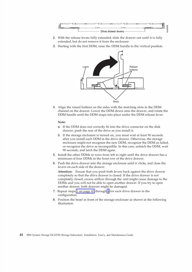
8/9/2019 Installation, User's, And Maintenance
http://slidepdf.com/reader/full/installation-users-and-maintenance 62/262
Drive drawer levers d c s q
0 0 0 5
2. With the release levers fully extended, slide the drawer out until it is fullyextended, but do not remove it from the enclosure.
3. Starting with the first DDM, raise the DDM handle to the vertical position.
Raisedbuttons
Slots
Latch
4. Align the raised buttons on the sides with the matching slots in the DDMchannel on the drawer. Lower the DDM down onto the drawer, and rotate theDDM handle until the DDM snaps into place under the DDM release lever.
Note:
a. If the DDM does not correctly fit into the drive connector on the diskdrawer, push the rear of the drive as you install it.
b. If the storage enclosure is turned on, you must wait at least 90 secondsafter you install each DDM in the drive drawer. Otherwise, the storage
enclosure might not recognize the new DDM, recognize the DDM as failed,or recognize the drive as incompatible. In this case, unlatch the DDM, wait90 seconds, and latch the DDM again.
5. Install the other DDMs in rows from left to right until the drive drawer has aminimum of four DDMs in the front row of the drive drawer.
6. Push the drive drawer into the storage enclosure until it clicks, and close thelevers on each side of the drawer.Attention: Ensure that you push both levers back against the drive drawercompletely so that the drive drawer is closed. If the drive drawer is notcompletely closed, excess airflow through the unit might cause damage to theDDMs and you will not be able to open another drawer. If you try to openanother drawer, both drawers might be damaged.
7. Repeat steps 1 on page 43 through 6 for each drive drawer in theconfiguration.
8. Position the bezel in front of the storage enclosure as shown in the followingillustration.
44 IBM System Storage DCS3700 Storage Subsystem: Installation, User's, and Maintenance Guide
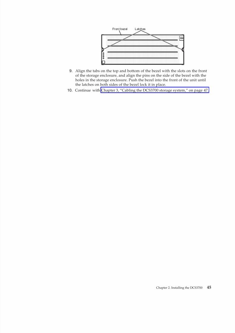
8/9/2019 Installation, User's, And Maintenance
http://slidepdf.com/reader/full/installation-users-and-maintenance 63/262
Front bezel Latches
9. Align the tabs on the top and bottom of the bezel with the slots on the frontof the storage enclosure, and align the pins on the side of the bezel with theholes in the storage enclosure. Push the bezel into the front of the unit untilthe latches on both sides of the bezel lock it in place.
10. Continue with Chapter 3, “Cabling the DCS3700 storage system,” on page 47.
Chapter 2. Installing the DCS3700 45

8/9/2019 Installation, User's, And Maintenance
http://slidepdf.com/reader/full/installation-users-and-maintenance 64/262
46 IBM System Storage DCS3700 Storage Subsystem: Installation, User's, and Maintenance Guide
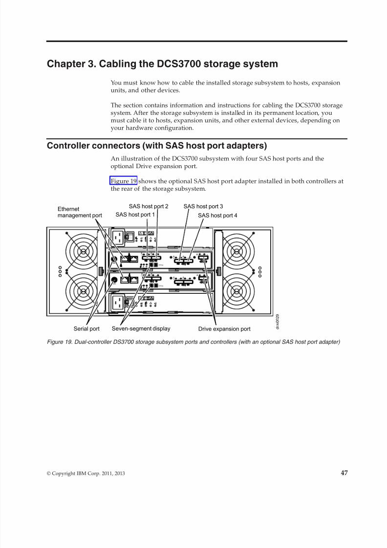
8/9/2019 Installation, User's, And Maintenance
http://slidepdf.com/reader/full/installation-users-and-maintenance 65/262
Chapter 3. Cabling the DCS3700 storage system
You must know how to cable the installed storage subsystem to hosts, expansionunits, and other devices.
The section contains information and instructions for cabling the DCS3700 storagesystem. After the storage subsystem is installed in its permanent location, youmust cable it to hosts, expansion units, and other external devices, depending onyour hardware configuration.
Controller connectors (with SAS host port adapters)
An illustration of the DCS3700 subsystem with four SAS host ports and theoptional Drive expansion port.
Figure 19 shows the optional SAS host port adapter installed in both controllers at
the rear of the storage subsystem.
d c s i 0 0 2 9
Lnk Lnk Lnk Lnk
ID/Diag
Ln k L nk
Lnk Lnk Lnk Lnk
ID/Diag
Ln k L nk
ACDC
2
1
I
O
ACDC
2
1
I
O
Ethernetmanagement port
Drive expansion port
SAS host port 1
Lnk Lnk Lnk Lnk
Lnk Lnk Lnk Lnk
Serial port Seven-segment display
SAS host port 2
SAS host port 4
SAS host port 3
Figure 19. Dual-controller DS3700 storage subsystem ports and controllers (with an optional SAS host port adapter)
© Copyright IBM Corp. 2011, 2013 47
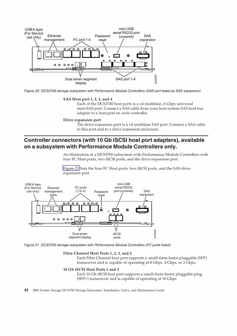
8/9/2019 Installation, User's, And Maintenance
http://slidepdf.com/reader/full/installation-users-and-maintenance 66/262
SAS Host port 1, 2, 3, and 4Each of the DCS3700 host ports is a x4 multilane, 6 Gbps universalmini-SAS port. Connect a SAS cable from your host system SAS host busadapter to a host port on each controller.
Drive expansion portThe drive expansion port is a x4 multilane SAS port. Connect a SAS cableto this port and to a drive expansion enclosure.
Controller connectors (with 10 Gb iSCSI host port adapters), available
on a subsystem with Performance Module Controllers only.
An illustration of a DCS3700 subsystem with Performance Module Controllers withfour FC Host ports, two iSCSI ports, and the drive expansion port.
Figure 21 lists the four FC Host ports, two iSCSI ports, and the SAS driveexpansion port.
Fibre Channel Host Ports 1, 2, 3, and 4Each Fibre Channel host port supports a small-form-factor pluggable (SFP)transceiver and is capable of operating at 8 Gbps, 4 Gbps, or 2 Gbps.
10 Gb iSCSI Host Ports 1 and 2Each 10 Gb iSCSI host port supports a small-form-factor pluggable plug(SFP+) transceiver and is capable of operating at 10 Gbps.
SASexpansion
mini-USBserial RS232 port
(covered)PasswordresetFC port 1-4
Ethernetmanagement
USB A-type(For Service
use only)
d c s i 0 0 4 3
SAS port 1-4Dual seven segmentdisplay
Figure 20. DCS3700 storage subsystem with Performance Module Controllers (SAS port listed as SAS expansion)
SASexpansion
mini-USBserial RS232port (covered)Password
reset
FC ports(1 to 4)
Ethernetmanagement
ports
USB A-type(For Service
use only)
d c s
i 0 0 4 4
iSCSIportsDual seven
segment display
Figure 21. DCS3700 storage subsystem with Performance Module Controllers (FC ports listed)
48 IBM System Storage DCS3700 Storage Subsystem: Installation, User's, and Maintenance Guide
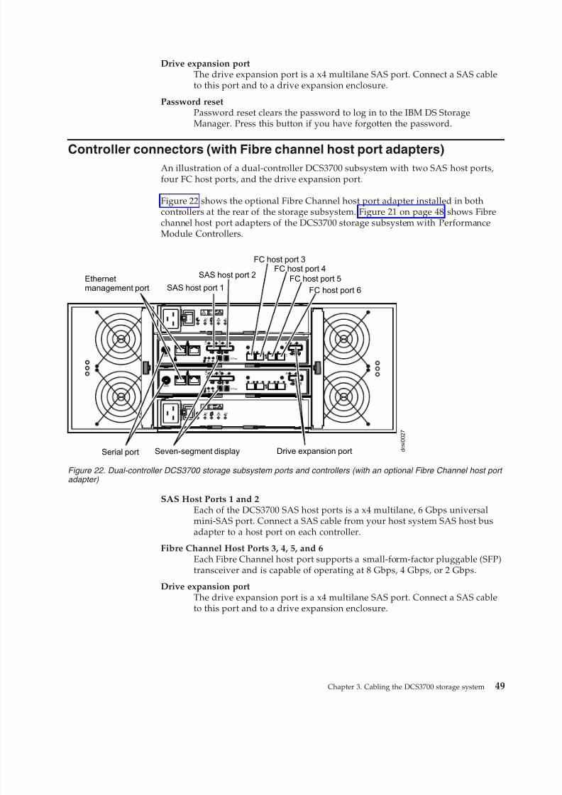
8/9/2019 Installation, User's, And Maintenance
http://slidepdf.com/reader/full/installation-users-and-maintenance 67/262
Drive expansion portThe drive expansion port is a x4 multilane SAS port. Connect a SAS cableto this port and to a drive expansion enclosure.
Password resetPassword reset clears the password to log in to the IBM DS StorageManager. Press this button if you have forgotten the password.
Controller connectors (with Fibre channel host port adapters)
An illustration of a dual-controller DCS3700 subsystem with two SAS host ports,four FC host ports, and the drive expansion port.
Figure 22 shows the optional Fibre Channel host port adapter installed in bothcontrollers at the rear of the storage subsystem. Figure 21 on page 48 shows Fibrechannel host port adapters of the DCS3700 storage subsystem with PerformanceModule Controllers.
SAS Host Ports 1 and 2Each of the DCS3700 SAS host ports is a x4 multilane, 6 Gbps universalmini-SAS port. Connect a SAS cable from your host system SAS host busadapter to a host port on each controller.
Fibre Channel Host Ports 3, 4, 5, and 6
Each Fibre Channel host port supports a small-form-factor pluggable (SFP)transceiver and is capable of operating at 8 Gbps, 4 Gbps, or 2 Gbps.
Drive expansion portThe drive expansion port is a x4 multilane SAS port. Connect a SAS cableto this port and to a drive expansion enclosure.
d c s i 0 0 2 7
Lnk Lnk Lnk Lnk
ID/Diag
L nk L nk
Lnk Lnk Lnk Lnk
ID/Diag
L nk L nk
ACDC
2
1
I
O
ACDC
2
1
I
O
Ethernetmanagement port
Drive expansion port
FC host port 6
2 48
2 48
2 48
2 48
FC
3
FC6
FC
4
5
2 48
2 48
2 48
2 48
FC3
FC
6FC
4
5
Serial port Seven-segment display
SAS host port 1SAS host port 2 FC host port 5
FC host port 4FC host port 3
Figure 22. Dual-controller DCS3700 storage subsystem ports and controllers (with an optional Fibre Channel host port adapter)
Chapter 3. Cabling the DCS3700 storage system 49

8/9/2019 Installation, User's, And Maintenance
http://slidepdf.com/reader/full/installation-users-and-maintenance 68/262
Fibre Channel Host Ports 1 to 8Each Fibre Channel host port supports a small-form-factor pluggable (SFP)transceiver and is capable of operating at 8 Gbps, 4 Gbps, or 2 Gbps.
Drive expansion port
The drive expansion port is a x4 multilane SAS port. Connect a SAS cableto this port and to a drive expansion enclosure.
Password resetPassword reset clears the password to log in to the IBM DS StorageManager. Press this button if you have forgotten the password.
Enclosure ID Settings
The enclosure ID is a unique two-digit identifier for each enclosure in the storagesubsystem configuration.
In a dual controller or ESM configuration, both enclosure IDs are identical under
normal operating conditions. Each DCS3700 storage system and DCS3700expansion enclosure in the storage subsystem configuration must have a uniquestorage enclosure ID.
The controller automatically sets the enclosure ID. You can change the settingthrough the DS Storage Manager software, if necessary. The range of supportedenclosure ID settings is 0 through 99. The enclosure ID is normally set to a value of 00 at the factory.
The enclosure ID is displayed on the seven-segment numeric display located onthe back of each controller and ESM.
Working with SAS cablesEach storage controller has up to four x4 multilane SAS host ports and a single x4multilane SAS port for drive channel connections.
Use a 1M or 3M (1-meter or 3-meter) SAS cable with a mini-SAS 4x multilane SASconnector on each end to connect a controller host port to a host HBA and toconnect the drive expansion port to an storage enclosure.
The following illustration shows the 1M and 3M mini-SAS cable.
SASexpansion
mini-USBserial RS232 port
(covered)Passwordreset
4-portbase 8 GBFC portsEthernet
management
USB A-type(For Service
use only)
d c s i 0 0 3 9
4-port 8 GBFC HIC
Dual seven segmentdisplay
Figure 23. FC HIC ports on a DCS3700 subsystem with Performance Module Controllers
50 IBM System Storage DCS3700 Storage Subsystem: Installation, User's, and Maintenance Guide
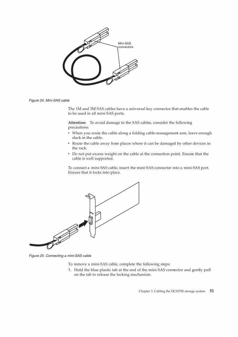
8/9/2019 Installation, User's, And Maintenance
http://slidepdf.com/reader/full/installation-users-and-maintenance 69/262
The 1M and 3M SAS cables have a universal key connector that enables the cableto be used in all mini-SAS ports.
Attention: To avoid damage to the SAS cables, consider the followingprecautions:v When you route the cable along a folding cable-management arm, leave enough
slack in the cable.v Route the cable away from places where it can be damaged by other devices in
the rack.v Do not put excess weight on the cable at the connection point. Ensure that the
cable is well supported.
To connect a mini-SAS cable, insert the mini-SAS connector into a mini-SAS port.Ensure that it locks into place.
To remove a mini-SAS cable, complete the following steps:
1. Hold the blue plastic tab at the end of the mini-SAS connector and gently pullon the tab to release the locking mechanism.
Mini-SASconnectors
Figure 24. Mini-SAS cable
Figure 25. Connecting a mini-SAS cable
Chapter 3. Cabling the DCS3700 storage system 51
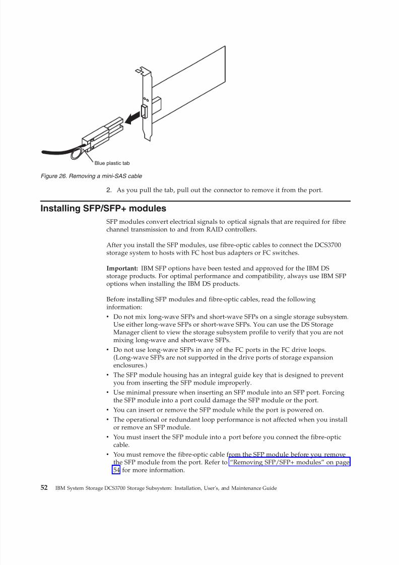
8/9/2019 Installation, User's, And Maintenance
http://slidepdf.com/reader/full/installation-users-and-maintenance 70/262
2. As you pull the tab, pull out the connector to remove it from the port.
Installing SFP/SFP+ modules
SFP modules convert electrical signals to optical signals that are required for fibrechannel transmission to and from RAID controllers.
After you install the SFP modules, use fibre-optic cables to connect the DCS3700storage system to hosts with FC host bus adapters or FC switches.
Important: IBM SFP options have been tested and approved for the IBM DSstorage products. For optimal performance and compatibility, always use IBM SFPoptions when installing the IBM DS products.
Before installing SFP modules and fibre-optic cables, read the followinginformation:v Do not mix long-wave SFPs and short-wave SFPs on a single storage subsystem.
Use either long-wave SFPs or short-wave SFPs. You can use the DS StorageManager client to view the storage subsystem profile to verify that you are notmixing long-wave and short-wave SFPs.
v Do not use long-wave SFPs in any of the FC ports in the FC drive loops.(Long-wave SFPs are not supported in the drive ports of storage expansionenclosures.)
v The SFP module housing has an integral guide key that is designed to preventyou from inserting the SFP module improperly.
v
Use minimal pressure when inserting an SFP module into an SFP port. Forcingthe SFP module into a port could damage the SFP module or the port.v You can insert or remove the SFP module while the port is powered on.v The operational or redundant loop performance is not affected when you install
or remove an SFP module.v You must insert the SFP module into a port before you connect the fibre-optic
cable.v You must remove the fibre-optic cable from the SFP module before you remove
the SFP module from the port. Refer to “Removing SFP/SFP+ modules” on page54 for more information.
Blue plastic tab
Figure 26. Removing a mini-SAS cable
52 IBM System Storage DCS3700 Storage Subsystem: Installation, User's, and Maintenance Guide
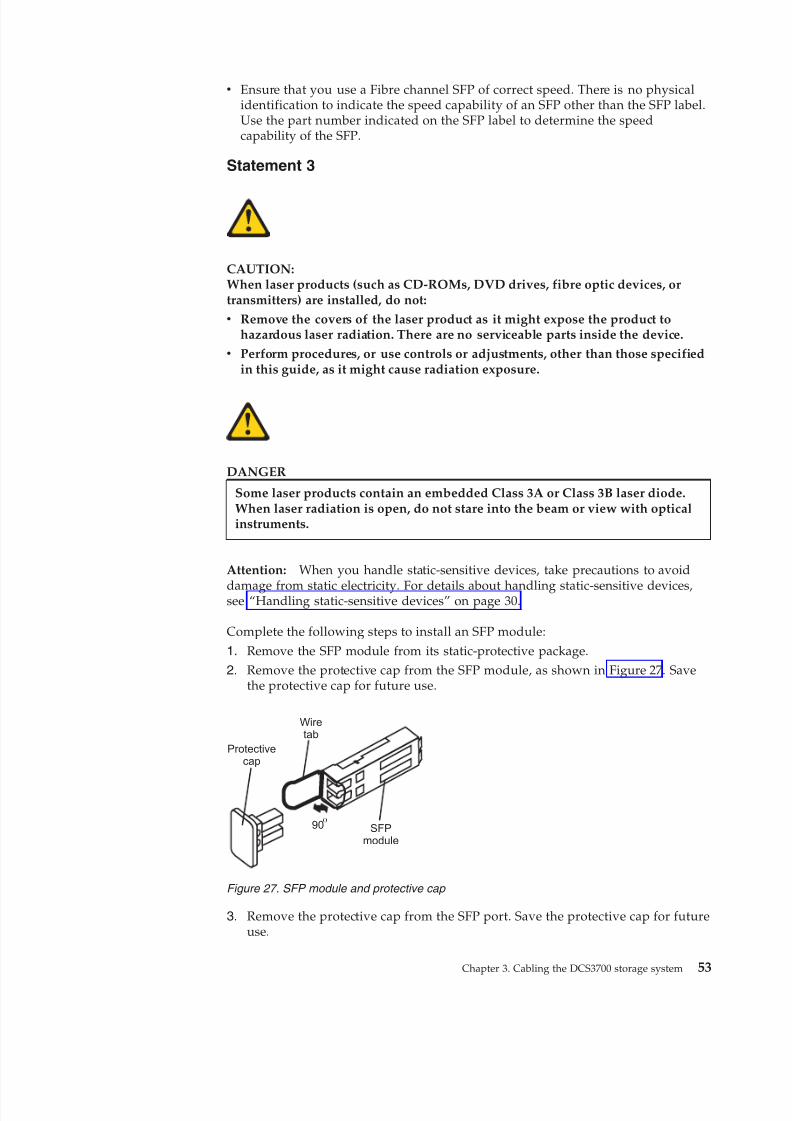
8/9/2019 Installation, User's, And Maintenance
http://slidepdf.com/reader/full/installation-users-and-maintenance 71/262
v Ensure that you use a Fibre channel SFP of correct speed. There is no physicalidentification to indicate the speed capability of an SFP other than the SFP label.Use the part number indicated on the SFP label to determine the speedcapability of the SFP.
Statement 3
CAUTION:When laser products (such as CD-ROMs, DVD drives, fibre optic devices, ortransmitters) are installed, do not:
v Remove the covers of the laser product as it might expose the product tohazardous laser radiation. There are no serviceable parts inside the device.
v Perform procedures, or use controls or adjustments, other than those specifiedin this guide, as it might cause radiation exposure.
DANGER
Some laser products contain an embedded Class 3A or Class 3B laser diode.When laser radiation is open, do not stare into the beam or view with opticalinstruments.
Attention: When you handle static-sensitive devices, take precautions to avoid
damage from static electricity. For details about handling static-sensitive devices,see “Handling static-sensitive devices” on page 30.
Complete the following steps to install an SFP module:
1. Remove the SFP module from its static-protective package.2. Remove the protective cap from the SFP module, as shown in Figure 27. Save
the protective cap for future use.
3. Remove the protective cap from the SFP port. Save the protective cap for futureuse.
o
Protectivecap
Wiretab
SFPmodule
90
Figure 27. SFP module and protective cap
Chapter 3. Cabling the DCS3700 storage system 53
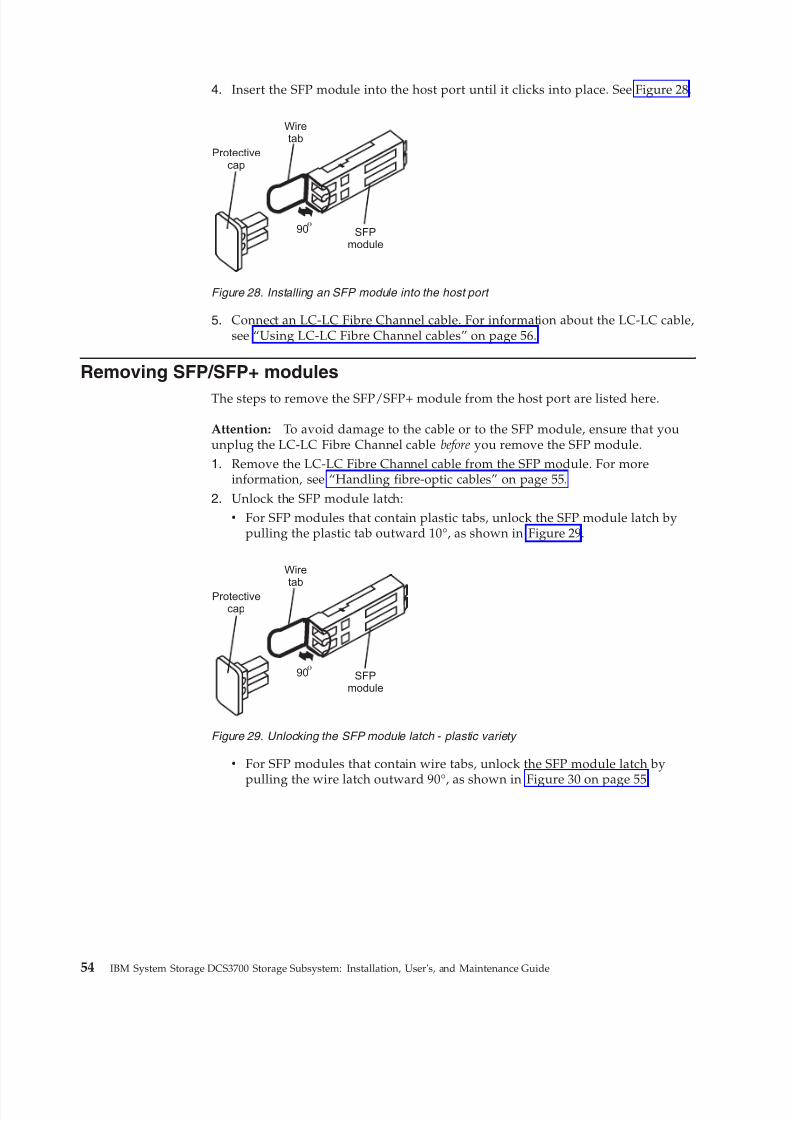
8/9/2019 Installation, User's, And Maintenance
http://slidepdf.com/reader/full/installation-users-and-maintenance 72/262
4. Insert the SFP module into the host port until it clicks into place. See Figure 28.
5. Connect an LC-LC Fibre Channel cable. For information about the LC-LC cable,see “Using LC-LC Fibre Channel cables” on page 56.
Removing SFP/SFP+ modules
The steps to remove the SFP/SFP+ module from the host port are listed here.
Attention: To avoid damage to the cable or to the SFP module, ensure that youunplug the LC-LC Fibre Channel cable before you remove the SFP module.1. Remove the LC-LC Fibre Channel cable from the SFP module. For more
information, see “Handling fibre-optic cables” on page 55.
2. Unlock the SFP module latch:v For SFP modules that contain plastic tabs, unlock the SFP module latch by
pulling the plastic tab outward 10°, as shown in Figure 29.
v For SFP modules that contain wire tabs, unlock the SFP module latch by
pulling the wire latch outward 90°, as shown in Figure 30 on page 55.
o
Protectivecap
Wiretab
SFPmodule
90
Figure 28. Installing an SFP module into the host port
o
Protectivecap
Wiretab
SFPmodule
90
Figure 29. Unlocking the SFP module latch - plastic variety
54 IBM System Storage DCS3700 Storage Subsystem: Installation, User's, and Maintenance Guide
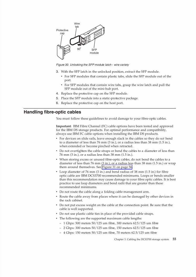
8/9/2019 Installation, User's, And Maintenance
http://slidepdf.com/reader/full/installation-users-and-maintenance 73/262
3. With the SFP latch in the unlocked position, extract the SFP module.v For SFP modules that contain plastic tabs, slide the SFP module out of the
port.v For SFP modules that contain wire tabs, grasp the wire latch and pull the
SFP module out of the mini-hub port.4. Replace the protective cap on the SFP module.
5. Place the SFP module into a static-protective package.6. Replace the protective cap on the host port.
Handling fibre-optic cables
You must follow these guidelines to avoid damage to your fibre-optic cables.
Important: IBM Fibre Channel (FC) cable options have been tested and approvedfor the IBM DS storage products. For optimal performance and compatibility,always use IBM FC cable options when installing the IBM DS products.v For devices on slide rails, leave enough slack in the cables so they do not bend
to a diameter of less than 76 mm (3 in.), or a radius less than 38 mm (1.5 in.),
when extended or become pinched when retracted.v Do not overtighten the cable straps or bend the cables to a diameter of less than
76 mm (3 in.), or a radius less than 38 mm (1.5 in.).v When storing excess or unused fibre-optic cables, do not bend the cables to a
diameter of less than 76 mm (3 in.), or a radius less than 38 mm (1.5 in.) or wrapthem around themselves. See Figure 31 on page 56.
v Loop diameter of 76 mm (3 in.) and bend radius of 38 mm (1.5 in.) for fibreoptic cable are IBM DCS3700 recommended minimums. Loops or bends smallerthan this recommendation may cause damage to your fibre optic cables. It is bestpractice to use loop diameters and bend radii that are greater than theserecommended minimums.
v Do not route the cable along a folding cable-management arm.v Route the cable away from places where it can be damaged by other devices in
the rack cabinet.v Do not put excess weight on the cable at the connection point. Be sure that the
cable is well supported.v Do not use plastic cable ties in place of the provided cable straps.v The following are the supported maximum cable lengths:
– 1 Gbps: 500 meters 50/125 um fibre, 300 meters 62.5/125 um fibre– 2 Gbps: 300 meters 50/125 um fibre, 150 meters 62.5/125 um fibre– 4 Gbps: 150 meters 50/125 um fibre, 70 meters 62.5/125 um fibre
o
Protectivecap
Wiretab
SFPmodule
90
Figure 30. Unlocking the SFP module latch - wire variety
Chapter 3. Cabling the DCS3700 storage system 55
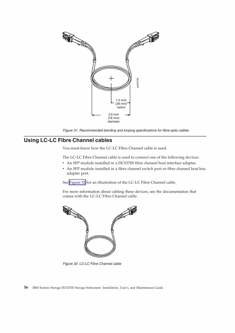
8/9/2019 Installation, User's, And Maintenance
http://slidepdf.com/reader/full/installation-users-and-maintenance 74/262
Using LC-LC Fibre Channel cables
You must know how the LC-LC Fibre Channel cable is used.
The LC-LC Fibre Channel cable is used to connect one of the following devices:v An SFP module installed in a DCS3700 fibre channel host interface adapter.v An SFP module installed in a fibre channel switch port or fibre channel host bus
adapter port.See Figure 32 for an illustration of the LC-LC Fibre Channel cable.
For more information about cabling these devices, see the documentation thatcomes with the LC-LC Fibre Channel cable.
1.5 inch(38 mm)radius
3.0 inch(76 mm)diameter
d s 4 7 0 1 0 4
Figure 31. Recommended bending and looping specifications for fibre-optic cables
Figure 32. LC-LC Fibre Channel cable
56 IBM System Storage DCS3700 Storage Subsystem: Installation, User's, and Maintenance Guide
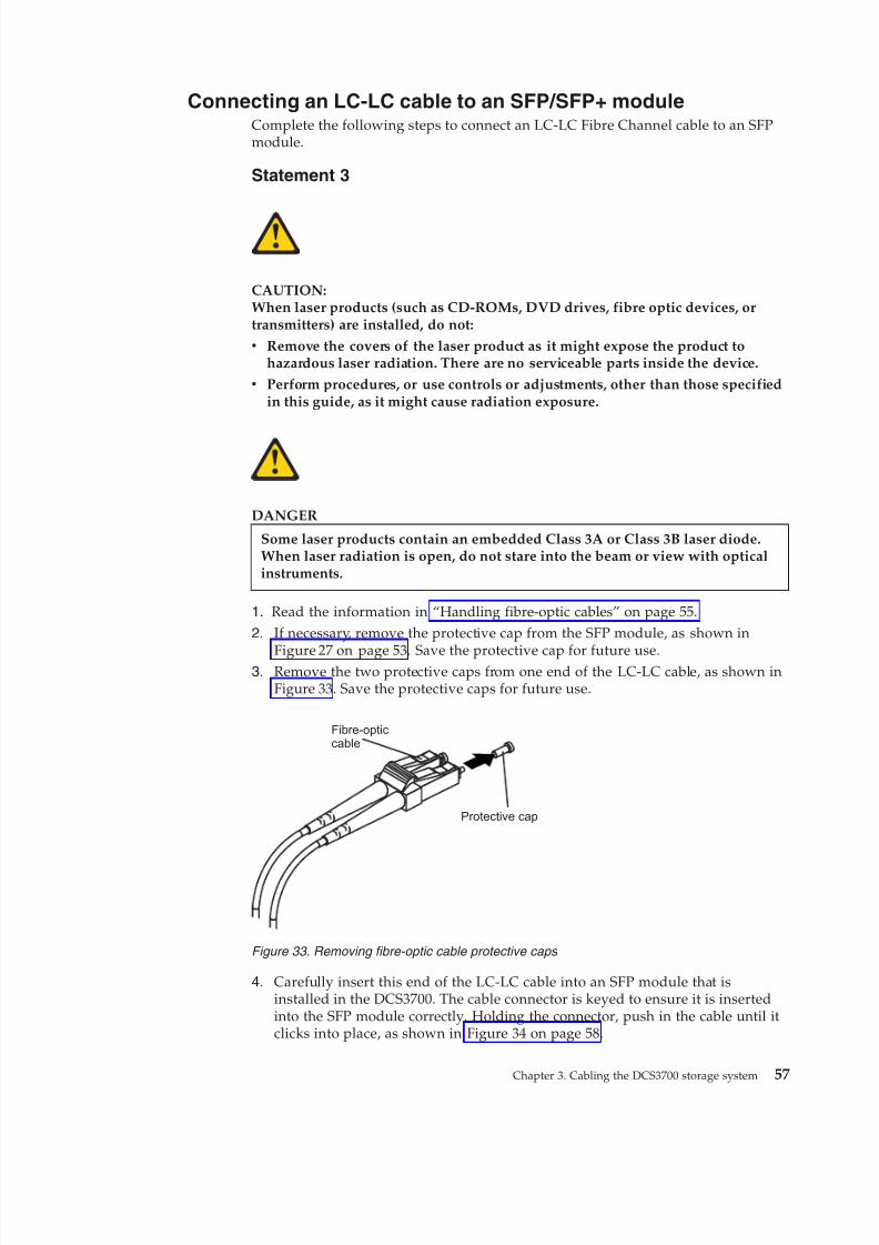
8/9/2019 Installation, User's, And Maintenance
http://slidepdf.com/reader/full/installation-users-and-maintenance 75/262
Connecting an LC-LC cable to an SFP/SFP+ moduleComplete the following steps to connect an LC-LC Fibre Channel cable to an SFPmodule.
Statement 3
CAUTION:When laser products (such as CD-ROMs, DVD drives, fibre optic devices, ortransmitters) are installed, do not:
v Remove the covers of the laser product as it might expose the product tohazardous laser radiation. There are no serviceable parts inside the device.
v Perform procedures, or use controls or adjustments, other than those specifiedin this guide, as it might cause radiation exposure.
DANGER
Some laser products contain an embedded Class 3A or Class 3B laser diode.When laser radiation is open, do not stare into the beam or view with opticalinstruments.
1. Read the information in “Handling fibre-optic cables” on page 55.
2. If necessary, remove the protective cap from the SFP module, as shown in
Figure 27 on page 53. Save the protective cap for future use.3. Remove the two protective caps from one end of the LC-LC cable, as shown in
Figure 33. Save the protective caps for future use.
4. Carefully insert this end of the LC-LC cable into an SFP module that isinstalled in the DCS3700. The cable connector is keyed to ensure it is insertedinto the SFP module correctly. Holding the connector, push in the cable until itclicks into place, as shown in Figure 34 on page 58.
Protective cap
Fibre-opticcable
Figure 33. Removing fibre-optic cable protective caps
Chapter 3. Cabling the DCS3700 storage system 57
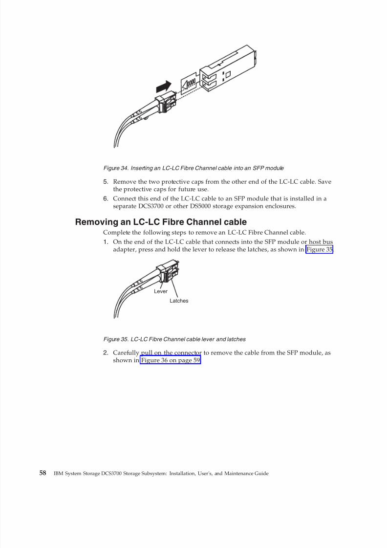
8/9/2019 Installation, User's, And Maintenance
http://slidepdf.com/reader/full/installation-users-and-maintenance 76/262
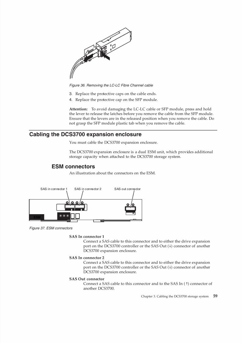
8/9/2019 Installation, User's, And Maintenance
http://slidepdf.com/reader/full/installation-users-and-maintenance 77/262
3. Replace the protective caps on the cable ends.
4. Replace the protective cap on the SFP module.
Attention: To avoid damaging the LC-LC cable or SFP module, press and holdthe lever to release the latches before you remove the cable from the SFP module.
Ensure that the levers are in the released position when you remove the cable. Donot grasp the SFP module plastic tab when you remove the cable.
Cabling the DCS3700 expansion enclosure
You must cable the DCS3700 expansion enclosure.
The DCS3700 expansion enclosure is a dual ESM unit, which provides additionalstorage capacity when attached to the DCS3700 storage system.
ESM connectorsAn illustration about the connectors on the ESM.
SAS In connector 1
Connect a SAS cable to this connector and to either the drive expansionport on the DCS3700 controller or the SAS Out (↓) connector of anotherDCS3700 expansion enclosure.
SAS In connector 2Connect a SAS cable to this connector and to either the drive expansionport on the DCS3700 controller or the SAS Out (↓) connector of anotherDCS3700 expansion enclosure.
SAS Out connectorConnect a SAS cable to this connector and to the SAS In (↑) connector of another DCS3700.
Figure 36. Removing the LC-LC Fibre Channel cable
1 2
ESM
SAS in connector 1 SAS in connector 2 SAS out connector
Figure 37. ESM connectors
Chapter 3. Cabling the DCS3700 storage system 59
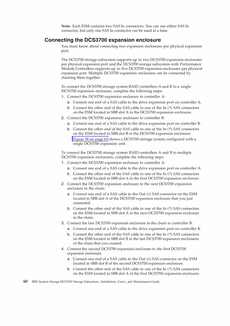
8/9/2019 Installation, User's, And Maintenance
http://slidepdf.com/reader/full/installation-users-and-maintenance 78/262
Note: Each ESM contains two SAS In connectors. You can use either SAS Inconnector, but only one SAS In connector can be used at a time.
Connecting the DCS3700 expansion enclosureYou must know about connecting two expansion enclosures per physical expansionport.
The DCS3700 storage subsystem supports up to two DCS3700 expansion enclosuresper physical expansion port and the DCS3700 storage subsystem with PerformanceModule Controllers supports up to five DCS3700 expansion enclosures per physicalexpansion port. Multiple DCS3700 expansion enclosures can be connected bychaining them together.
To connect the DCS3700 storage system RAID controllers A and B to a singleDCS3700 expansion enclosure, complete the following steps:
1. Connect the DCS3700 expansion enclosure to controller A:
a. Connect one end of a SAS cable to the drive expansion port on controller A.b. Connect the other end of the SAS cable to one of the In (↑) SAS connectors
on the ESM located in SBB slot A in the DCS3700 expansion enclosure.2. Connect the DCS3700 expansion enclosure to controller B:a. Connect one end of a SAS cable to the drive expansion port on controller B.b. Connect the other end of the SAS cable to one of the In (↑) SAS connectors
on the ESM located in SBB slot B in the DCS3700 expansion enclosure.Figure 38 on page 61 shows a DCS3700 storage system configured with asingle DCS3700 expansion unit.
To connect the DCS3700 storage system RAID controllers A and B to multipleDCS3700 expansion enclosures, complete the following steps:1. Connect the DCS3700 expansion enclosure to controller A:
a. Connect one end of a SAS cable to the drive expansion port on controller A.
b. Connect the other end of the SAS cable to one of the In (↑) SAS connectorson the ESM located in SBB slot A in the first DCS3700 expansion enclosure.
2. Connect the DCS3700 expansion enclosure to the next DCS3700 expansionenclosure in the chain:
a. Connect one end of a SAS cable to the Out (↓) SAS connector on the ESMlocated in SBB slot A of the DCS3700 expansion enclosure that you justconnected.
b. Connect the other end of the SAS cable to one of the In (↑) SAS connectorson the ESM located in SBB slot A in the next DCS3700 expansion enclosurein the chain.
3. Connect the last DCS3700 expansion enclosure in the chain to controller B:
a. Connect one end of a SAS cable to the drive expansion port on controller B.b. Connect the other end of the SAS cable to one of the In (↑) SAS connectors
on the ESM located in SBB slot B in the last DCS3700 expansion enclosuresof the chain that you created.
4. Connect the second DCS3700 expansion enclosure to the first DCS3700expansion enclosure.a. Connect one end of a SAS cable to the Out (↓) SAS connector on the ESM
located in SBB slot B of the second DCS3700 expansion enclosure.
b. Connect the other end of the SAS cable to one of the In (↑) SAS connectorson the ESM located in SBB slot A of the first DCS3700 expansion enclosure.
60 IBM System Storage DCS3700 Storage Subsystem: Installation, User's, and Maintenance Guide
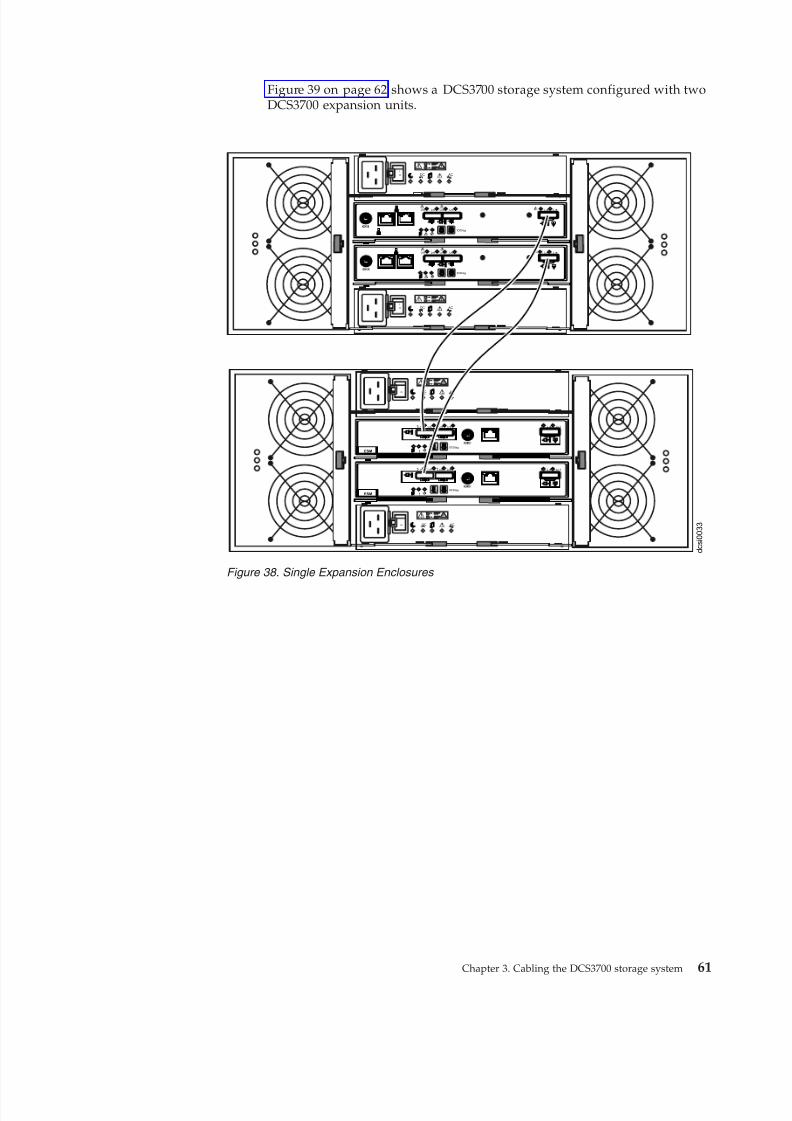
8/9/2019 Installation, User's, And Maintenance
http://slidepdf.com/reader/full/installation-users-and-maintenance 79/262
Figure 39 on page 62 shows a DCS3700 storage system configured with twoDCS3700 expansion units.
d c s i 0 0 3 3
L nk Ln k
ACDC
2
1
I
O
ACDC
2
1
I
O
!
ID/Diag
!
Lnk Lnk Lnk Lnk! !
ESM
L nk Ln k!
ID/Diag
!
Lnk Lnk Lnk Lnk! !
ESM
Lnk Lnk Lnk Lnk
ID/Diag
L nk L nk
Lnk Lnk Lnk Lnk
ID/Diag
L nk L nk
ACDC
2
1
I
O
ACDC
2
1
I
O
Figure 38. Single Expansion Enclosures
Chapter 3. Cabling the DCS3700 storage system 61
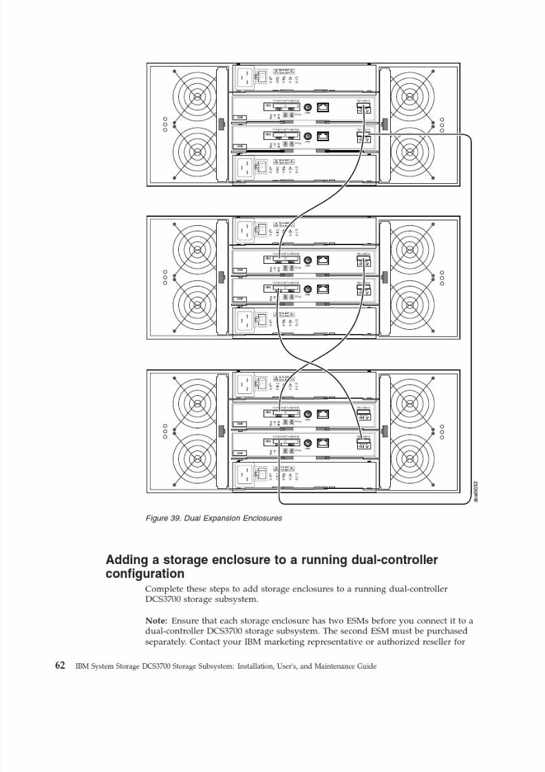
8/9/2019 Installation, User's, And Maintenance
http://slidepdf.com/reader/full/installation-users-and-maintenance 80/262
8/9/2019 Installation, User's, And Maintenance
http://slidepdf.com/reader/full/installation-users-and-maintenance 81/262
more information about purchasing a second ESM. For more information aboutinstalling a second ESM, see the Installation Guide that is shipped with the storageenclosure.
1. Ensure that the DCS3700 storage subsystem status is Optimal in the StorageManager software.
2. Use the storage enclosure Rack Installation Instructions document to install
the new storage enclosure in the rack.3. Connect the power cables to the new storage enclosure.4. Power on the storage enclosure.5. Connect one end of a Serial Attached SCSI (SAS) cable to the Drive expansion
port on Controller A in the DCS3700 storage subsystem.
6. Connect the other end of the SAS cable to either of the In ports on the leftESM in the storage enclosure.
7. Connect one end of a second SAS cable to the Drive expansion port onController B in the DCS3700 storage subsystem.
8. Connect the other end of the second SAS cable to the In port on the right ESMin the storage enclosure.
9. Wait until the storage subsystem status is Optimal in the Storage Managersoftware before proceeding to step 10.10. Add the drives to the storage enclosure. Ensure that you wait for at least 30
seconds for the Storage Manager software to recognize each newly addeddrive before you install another drive.To add additional storage enclosures after the first storage enclosure isconnected to a dual-controller DCS3700 storage subsystem, complete thefollowing steps:
a. Ensure that the storage subsystem status is Optimal in the StorageManager software.
b. Use the storage enclosure Rack Installation Instructions document to installthe new storage enclosure in the rack.
c. Connect the power cables to the new storage enclosure.d. Power on the storage enclosure.e. Connect one end of a Serial Attached SCSI (SAS) cable to the In port on
the left ESM in the storage enclosure that is being added to theconfiguration.
f. Connect the other end of the SAS cable to the Out port on the left ESM inthe last storage enclosure in the configuration (this storage enclosure isdirectly connected to the Drive expansion port on controller A of theDCS3700).
g. On the last storage enclosure in the configuration, disconnect the SAScable from the In port on the right ESM and connect it to the In port onthe right ESM on the new storage enclosure that is being added to theconfiguration.
Note: When the SAS cable is disconnected, a loss of path redundancyoccurs and an error message is displayed in the Storage Manager RecoveryGuru. Ignore this error message. The redundant path is restored in thenext step after the SAS cable is connected.
h. Connect a SAS cable to the Out port on the right ESM of the new storageenclosure and connect the other end to either of the In port on the rightESM in the storage enclosure that was previously connected to controller Bof the DCS3700.
Chapter 3. Cabling the DCS3700 storage system 63
8/9/2019 Installation, User's, And Maintenance
http://slidepdf.com/reader/full/installation-users-and-maintenance 82/262
i. Wait until the storage subsystem status is Optimal in the Storage Managersoftware before proceeding to the next step.
j. Add the drives to the storage enclosure. Ensure that you wait for at least 30seconds for the Storage Manager software to recognize each newly addeddrive before you install another drive.
Redundant drive channel pairThe drive channel from each controller of a dual-controller DCS3700 combine toform a redundant drive channel pair.
Each storage controller on the DCS3700 storage system has a drive expansionchannel that contains an x4 SAS port. The storage expansion enclosures that areconnected to this connector form a drive channel. The maximum number of drivesthat can be installed in one drive channel is 180. In a dual-controller DCS3700, onedrive channel from each controller combines to form a redundant drive-channelpair. For a DCS3700 subsystem with Performance Module Controllers, themaximum number of drives that can be installed in one drive channel is 360. If any component of the drive channel fails, the controllers can still access the storageenclosures in the redundant drive-channel pair.
Connecting secondary interface cablesThis section applies to direct (out-of-band) management configurations only. If your configuration uses host-agent (in-band) management, skip this section.
Use the Ethernet management port on the rear of the DCS3700 system storagecontrollers for direct management of the storage subsystems (see Figure 41 on page66).
Important:
1. To minimize security risks, do not connect the DCS3700 to a public LAN orpublic subnet. Use a local private network for the DCS3700 and the storage
management station Ethernet connectors.2. For proper EMI shielding, always use quality braided and if necessary, shielded
cables.
Connect an Ethernet cable from the management station to the Ethernet connectoron controller A and controller B on the rear of the DCS3700 storage system.
Configuring the storage subsystemYou must configure the storage system and the enclosure you have installed.
After you install the DCS3700 storage system and DCS3700 expansion enclosuresin a rack, it is necessary to configure the storage subsystem. Use the information in
the following sections to configure your storage subsystem.
Storage subsystem management methodsYou can manage the storage subsystems in one of these two ways: host-agent(in-band) management or direct (out-of-band) management.
Before you configure the storage subsystem, determine which method of storagesubsystem management you want to use.
64 IBM System Storage DCS3700 Storage Subsystem: Installation, User's, and Maintenance Guide
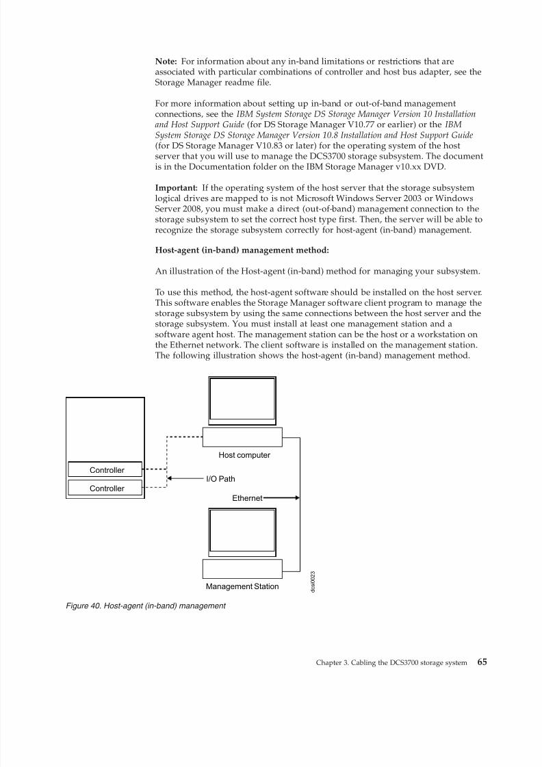
8/9/2019 Installation, User's, And Maintenance
http://slidepdf.com/reader/full/installation-users-and-maintenance 83/262
Note: For information about any in-band limitations or restrictions that areassociated with particular combinations of controller and host bus adapter, see theStorage Manager readme file.
For more information about setting up in-band or out-of-band managementconnections, see the IBM System Storage DS Storage Manager Version 10 Installationand Host Support Guide (for DS Storage Manager V10.77 or earlier) or the IBM
System Storage DS Storage Manager Version 10.8 Installation and Host Support Guide(for DS Storage Manager V10.83 or later) for the operating system of the hostserver that you will use to manage the DCS3700 storage subsystem. The documentis in the Documentation folder on the IBM Storage Manager v10.xx DVD.
Important: If the operating system of the host server that the storage subsystemlogical drives are mapped to is not Microsoft Windows Server 2003 or WindowsServer 2008, you must make a direct (out-of-band) management connection to thestorage subsystem to set the correct host type first. Then, the server will be able torecognize the storage subsystem correctly for host-agent (in-band) management.
Host-agent (in-band) management method:
An illustration of the Host-agent (in-band) method for managing your subsystem.
To use this method, the host-agent software should be installed on the host server.This software enables the Storage Manager software client program to manage thestorage subsystem by using the same connections between the host server and thestorage subsystem. You must install at least one management station and asoftware agent host. The management station can be the host or a workstation onthe Ethernet network. The client software is installed on the management station.The following illustration shows the host-agent (in-band) management method.
d c s i 0 0 2 3
Controller
Controller
Host computer
Management Station
I/O Path
Ethernet
Figure 40. Host-agent (in-band) management
Chapter 3. Cabling the DCS3700 storage system 65
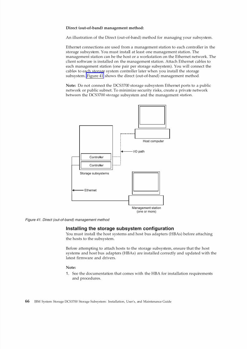
8/9/2019 Installation, User's, And Maintenance
http://slidepdf.com/reader/full/installation-users-and-maintenance 84/262
Direct (out-of-band) management method:
An illustration of the Direct (out-of-band) method for managing your subsystem.
Ethernet connections are used from a management station to each controller in thestorage subsystem. You must install at least one management station. Themanagement station can be the host or a workstation on the Ethernet network. The
client software is installed on the management station. Attach Ethernet cables toeach management station (one pair per storage subsystem). You will connect thecables to each storage system controller later when you install the storagesubsystem. Figure 41 shows the direct (out-of-band) management method.
Note: Do not connect the DCS3700 storage subsystem Ethernet ports to a publicnetwork or public subnet. To minimize security risks, create a private network
between the DCS3700 storage subsystem and the management station.
Installing the storage subsystem configurationYou must install the host systems and host bus adapters (HBAs) before attachingthe hosts to the subsystem.
Before attempting to attach hosts to the storage subsystem, ensure that the hostsystems and host bus adapters (HBAs) are installed correctly and updated with thelatest firmware and drivers.
Note:
1. See the documentation that comes with the HBA for installation requirementsand procedures.
Figure 41. Direct (out-of-band) management method
66 IBM System Storage DCS3700 Storage Subsystem: Installation, User's, and Maintenance Guide
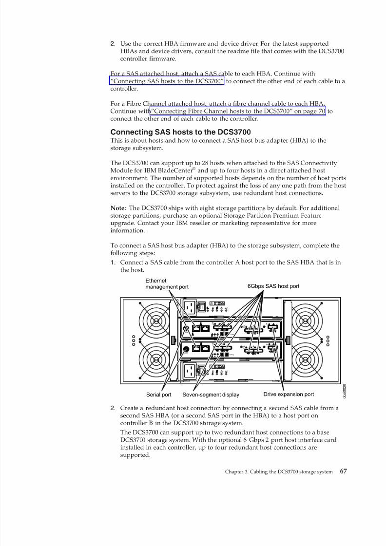
8/9/2019 Installation, User's, And Maintenance
http://slidepdf.com/reader/full/installation-users-and-maintenance 85/262
2. Use the correct HBA firmware and device driver. For the latest supportedHBAs and device drivers, consult the readme file that comes with the DCS3700controller firmware.
For a SAS attached host, attach a SAS cable to each HBA. Continue with“Connecting SAS hosts to the DCS3700” to connect the other end of each cable to acontroller.
For a Fibre Channel attached host, attach a fibre channel cable to each HBA.Continue with“Connecting Fibre Channel hosts to the DCS3700” on page 70 toconnect the other end of each cable to the controller.
Connecting SAS hosts to the DCS3700This is about hosts and how to connect a SAS host bus adapter (HBA) to thestorage subsystem.
The DCS3700 can support up to 28 hosts when attached to the SAS ConnectivityModule for IBM BladeCenter® and up to four hosts in a direct attached hostenvironment. The number of supported hosts depends on the number of host portsinstalled on the controller. To protect against the loss of any one path from the host
servers to the DCS3700 storage subsystem, use redundant host connections.
Note: The DCS3700 ships with eight storage partitions by default. For additionalstorage partitions, purchase an optional Storage Partition Premium Featureupgrade. Contact your IBM reseller or marketing representative for moreinformation.
To connect a SAS host bus adapter (HBA) to the storage subsystem, complete thefollowing steps:
1. Connect a SAS cable from the controller A host port to the SAS HBA that is inthe host.
d c s i 0 0 2 8
Lnk Lnk Lnk Lnk
ID/Diag
L nk L nk
Lnk Lnk Lnk Lnk
ID/Diag
L nk L nk
ACDC
2
1
I
O
ACDC
2
1
I
O
Ethernet
management port
Drive expansion port
6Gbps SAS host port
Lnk Lnk Lnk Lnk
Lnk Lnk Lnk Lnk
Serial port Seven-segment display
2. Create a redundant host connection by connecting a second SAS cable from asecond SAS HBA (or a second SAS port in the HBA) to a host port oncontroller B in the DCS3700 storage system.The DCS3700 can support up to two redundant host connections to a baseDCS3700 storage system. With the optional 6 Gbps 2 port host interface cardinstalled in each controller, up to four redundant host connections aresupported.
Chapter 3. Cabling the DCS3700 storage system 67
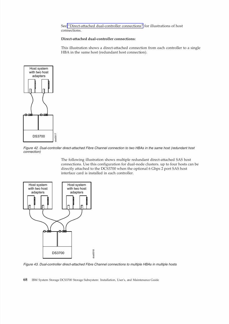
8/9/2019 Installation, User's, And Maintenance
http://slidepdf.com/reader/full/installation-users-and-maintenance 86/262
See “Direct-attached dual-controller connections” for illustrations of hostconnections.
Direct-attached dual-controller connections:
This illustration shows a direct-attached connection from each controller to a singleHBA in the same host (redundant host connection).
The following illustration shows multiple redundant direct-attached SAS hostconnections. Use this configuration for dual-node clusters. up to four hosts can be
directly attached to the DCS3700 when the optional 6 Gbps 2 port SAS hostinterface card is installed in each controller.
DS3700
d c s i 0 0 1 7
Host systemwith two host
adapters
Figure 42. Dual-controller direct-attached Fibre Channel connection to two HBAs in the same host (redundant host connection)
d c s i 0 0 1 8
Host systemwith two host
adapters
Host systemwith two host
adapters
DS3700
Figure 43. Dual-controller direct-attached Fibre Channel connections to multiple HBAs in multiple hosts
68 IBM System Storage DCS3700 Storage Subsystem: Installation, User's, and Maintenance Guide
8/9/2019 Installation, User's, And Maintenance
http://slidepdf.com/reader/full/installation-users-and-maintenance 87/262
Overview of installing an IBM BladeCenter configuration to connect to
a DCS3700
This section gives an overview and guidelines for installing an IBM BladeCenterconfiguration to connect to a DCS3700 storage system.
Before you install the BladeCenter configuration:v Ensure that the BladeCenter chassis, blade server, SAS connectivity module, and
SAS expansion card are supported. Go to http://www.ibm.com/systems/support/storage/ssic/interoperability.wss and check the System StorageInteroperation Center for details of the hardware supported by the DCS3700storage system.
v Ensure that an Advanced Management Module is installed in the BladeCenterchassis. The latest level of management-module firmware is available athttp://www.ibm.com/bladecenter/.
v For the latest SAS connectivity module firmware, SAS expansion card firmware, blade server BIOS code, and device drivers, see http://www.ibm.com/systems/support/.
Installing the BladeCenter configurationYou can install the BladeCenter configuration in three steps.1. Install an IBM BladeCenter SAS Expansion Card (CFFv) in each blade server
that you want to connect to the DCS3700. See the documentation that comeswith the SAS expansion card for installation requirements and procedures.
2. Install the blade servers in the BladeCenter chassis. See the documentation thatcomes with the blade server for installation requirements and procedures.
3. Install the IBM BladeCenter SAS Connectivity Modules in the I/O bays inBladeCenter unit. See the documentation that comes with the SAS connectivitymodules for installation requirements and procedures.
4. Follow the instructions under “Connecting BladeCenter hosts to the DCS3700.”
Connecting BladeCenter hosts to the DCS3700The steps to connect the BladeCenter to the two SAS host connectors on eachcontroller of the DCS3700 are listed here.
The dual-controller DCS3700 comes with two SAS host connectors on eachcontroller, enabling up to 28 blade servers in two BladeCenter units to beredundantly connected to the storage subsystem.
To protect against the loss of any one path from the host blade servers to theDCS3700, use redundant host connections.
To connect a SAS expansion card that is installed in a blade server to the DCS3700,complete the following steps:1. Connect a SAS cable from the SAS host connector on the DCS3700 storage
system to any SAS port on an IBM BladeCenter SAS Connectivity Module thatis installed in a BladeCenter unit (port 3 is recommended).
2. To create a redundant host connection, connect a SAS cable from a second SASconnectivity module to a host connector on the other controller in the DCS3700.You can only create up to two redundant host connections in a dual-controllerDCS3700, one connection each from the blade center to the DCS3700 controllerhost port as shown in Figure 44 on page 70.
Chapter 3. Cabling the DCS3700 storage system 69
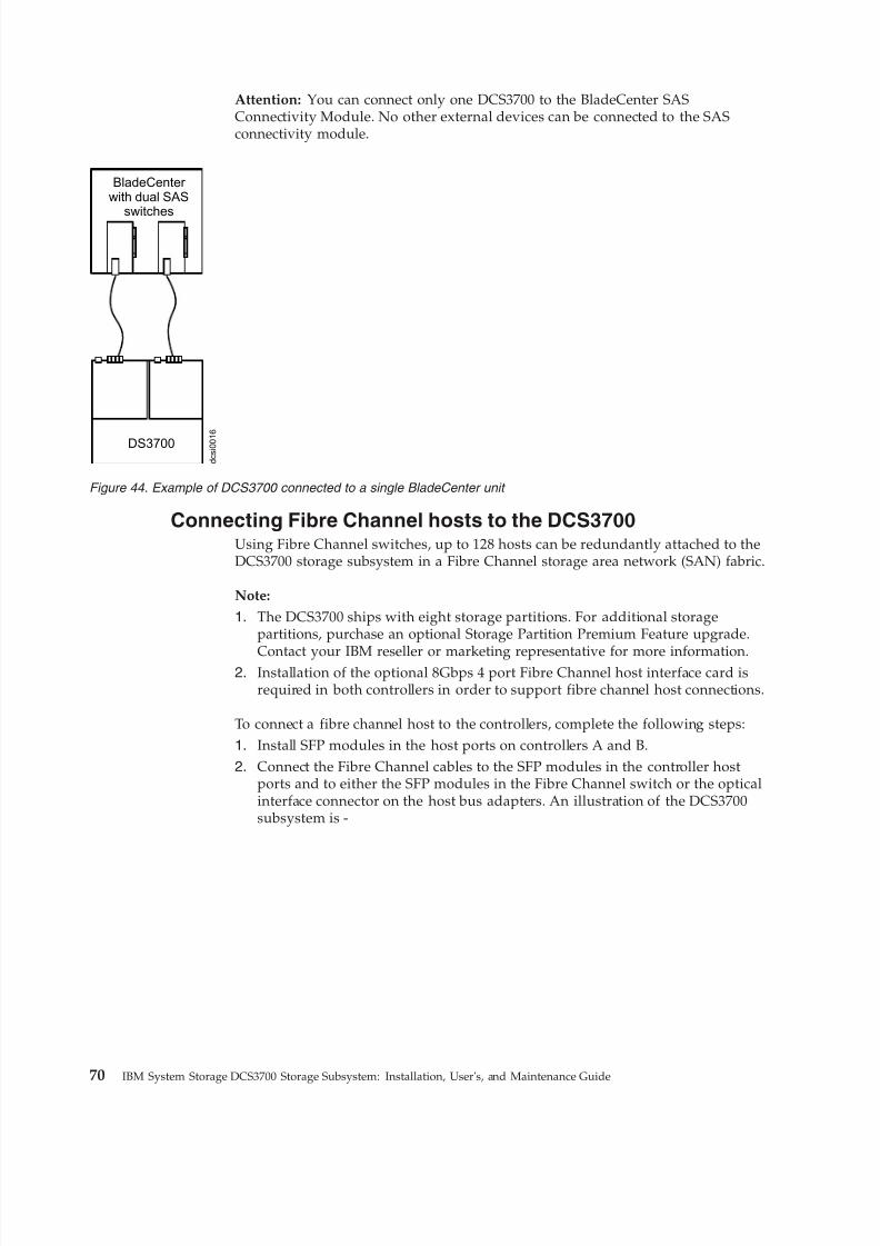
8/9/2019 Installation, User's, And Maintenance
http://slidepdf.com/reader/full/installation-users-and-maintenance 88/262
Attention: You can connect only one DCS3700 to the BladeCenter SASConnectivity Module. No other external devices can be connected to the SASconnectivity module.
Connecting Fibre Channel hosts to the DCS3700Using Fibre Channel switches, up to 128 hosts can be redundantly attached to theDCS3700 storage subsystem in a Fibre Channel storage area network (SAN) fabric.
Note:
1. The DCS3700 ships with eight storage partitions. For additional storagepartitions, purchase an optional Storage Partition Premium Feature upgrade.
Contact your IBM reseller or marketing representative for more information.2. Installation of the optional 8Gbps 4 port Fibre Channel host interface card is
required in both controllers in order to support fibre channel host connections.
To connect a fibre channel host to the controllers, complete the following steps:1. Install SFP modules in the host ports on controllers A and B.2. Connect the Fibre Channel cables to the SFP modules in the controller host
ports and to either the SFP modules in the Fibre Channel switch or the opticalinterface connector on the host bus adapters. An illustration of the DCS3700subsystem is -
d c s i 0 0 1
6
BladeCenter with dual SAS
switches
DS3700
Figure 44. Example of DCS3700 connected to a single BladeCenter unit
70 IBM System Storage DCS3700 Storage Subsystem: Installation, User's, and Maintenance Guide
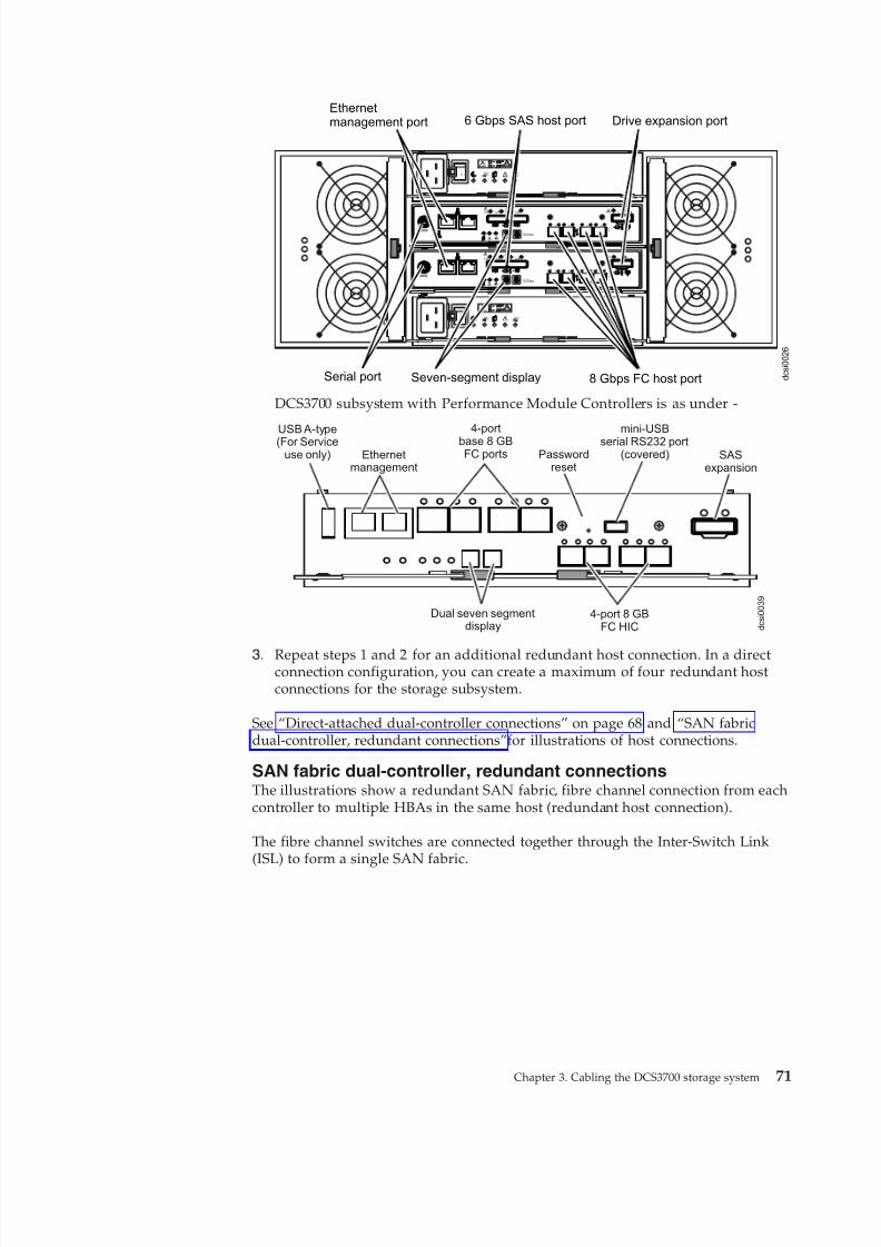
8/9/2019 Installation, User's, And Maintenance
http://slidepdf.com/reader/full/installation-users-and-maintenance 89/262
d c s i 0 0 2 6
Lnk Lnk Lnk Lnk
ID/Diag
L nk L nk
Lnk Lnk Lnk Lnk
ID/Diag
L nk L nk
ACDC
2
1
I
O
ACDC
2
1
I
O
Ethernetmanagement port Drive expansion port
8 Gbps FC host port
2 48
2 48
2 48
2 48
FC
3
FC
6
FC
4
5
2 48
2 48
2 48
2 48
FC
3
FC
6
FC
4
5
Serial port Seven-segment display
6 Gbps SAS host port
DCS3700 subsystem with Performance Module Controllers is as under -
SASexpansion
mini-USBserial RS232 port
(covered)Passwordreset
4-portbase 8 GBFC portsEthernet
management
USB A-type(For Service
use only)
d c s i 0 0 3 9
4-port 8 GBFC HIC
Dual seven segmentdisplay
3. Repeat steps 1 and 2 for an additional redundant host connection. In a directconnection configuration, you can create a maximum of four redundant hostconnections for the storage subsystem.
See “Direct-attached dual-controller connections” on page 68 and “SAN fabricdual-controller, redundant connections”f or illustrations of host connections.
SAN fabric dual-controller, redundant connectionsThe illustrations show a redundant SAN fabric, fibre channel connection from eachcontroller to multiple HBAs in the same host (redundant host connection).
The fibre channel switches are connected together through the Inter-Switch Link(ISL) to form a single SAN fabric.
Chapter 3. Cabling the DCS3700 storage system 71
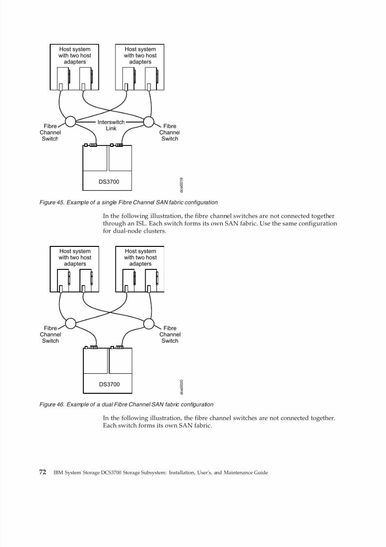
8/9/2019 Installation, User's, And Maintenance
http://slidepdf.com/reader/full/installation-users-and-maintenance 90/262
In the following illustration, the fibre channel switches are not connected togetherthrough an ISL. Each switch forms its own SAN fabric. Use the same configurationfor dual-node clusters.
In the following illustration, the fibre channel switches are not connected together.Each switch forms its own SAN fabric.
d c s i 0 0 1 9
Host systemwith two host
adapters
Host systemwith two host
adapters
FibreChannelSwitch
FibreChannelSwitch
InterswitchLink
DS3700
Figure 45. Example of a single Fibre Channel SAN fabric configuration
d c s i 0 0 2
0
Host systemwith two host
adapters
Host systemwith two host
adapters
FibreChannelSwitch
FibreChannelSwitch
DS3700
Figure 46. Example of a dual Fibre Channel SAN fabric configuration
72 IBM System Storage DCS3700 Storage Subsystem: Installation, User's, and Maintenance Guide
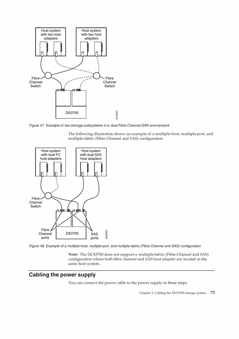
8/9/2019 Installation, User's, And Maintenance
http://slidepdf.com/reader/full/installation-users-and-maintenance 91/262
The following illustration shows an example of a multiple-host, multiple-port, andmultiple-fabric (Fibre Channel and SAS) configuration
Note: The DCS3700 does not support a multiple-fabric (Fibre Channel and SAS)configuration where both fibre channel and SAS host adapter are located in thesame host system.
Cabling the power supply
You can connect the power cable to the power supply in three steps.
d c s i 0 0 2 1
Host systemwith two host
adapters
Host systemwith two host
adapters
FibreChannelSwitch
FibreChannelSwitch
DS3700
Figure 47. Example of two storage subsystems in a dual Fibre Channel SAN environment
DS3700
d c
s i 0 0 2 2
Host systemwith dual FChost adapters
FibreChannelSwitch
Host systemwith dual SAShost adapters
FibreChannel
ports
SAS
ports
Figure 48. Example of a multiple-host, multiple-port, and multiple-fabric (Fibre Channel and SAS) configuration
Chapter 3. Cabling the DCS3700 storage system 73
8/9/2019 Installation, User's, And Maintenance
http://slidepdf.com/reader/full/installation-users-and-maintenance 92/262
The DCS3700 requires 200-240V AC power. Ensure that it is connected only to thecorrect AC supply voltage. If there are multiple DCS3700 units to be connected,ensure that the AC source and the rack Power Distribution Unit current ratings aresufficient to support the DCS3700 operating and surge current requirements.
Complete the following steps to connect the power supply cable.1. Using the strap that is provided with the power supply, tie the power supply
cord to the strap to provide strain relief and to prevent the power cord fromaccidently being unplugged.
2. Connect the power cable to the power supply.3. Continue with “Powering on the DCS3700” on page 77 for the initial startup of
the storage expansion enclosure.
Relocating the DCS3700
Using the rack relocation kit, you can relocate the populated DCS3700 storagesubsystem.
Before you move a DCS3700 with populated hard drive drawers, you must obtain
a relocation kit.v You can unmount the subsystem from the rack and move the subsystem alone.
Use the DS/DCS dense drive enclosure relocation kit.v You can also move the rack with the system mounted in it. Use the rack
relocation kit.
Follow the instructions provided with the relocation kit to avoid potential damageto the DCS3700:v You must remove the drives from the DCS3700 and place them in the boxes that
come with the relocating kit.v You must label the drives using the labels that come with the relocating kit.v
A lift tool must be used if the DCS3700 is to be removed from the rack.
74 IBM System Storage DCS3700 Storage Subsystem: Installation, User's, and Maintenance Guide
8/9/2019 Installation, User's, And Maintenance
http://slidepdf.com/reader/full/installation-users-and-maintenance 93/262
Chapter 4. Operating the DCS3700 storage system andexpansion enclosure
This section describes operating procedures for the DCS3700 storage system andexpansion enclosure.
To ensure optimal operation of your DCS3700 storage system and expansionenclosure, see “Best practices guidelines” on page 6.
Performing the DCS3700 Health Check process
Use the health check process to help you verify and maintain the optimalperformance of the storage configuration.
The information that you collect in these steps also helps provide IBM Service withimportant information that is needed during a service call.
Conduct the following health checks after the initial configuration of the storagesubsystem and after all configuration sessions.
1. Monitor the Recovery Guru in the Storage Manager software for any obviousstorage subsystem errors or problem conditions.
2. Gather and save the following storage subsystem event logs for review by IBMService. These event logs should be gathered periodically for regular healthcheck monitoring regardless of the state of the Recovery Guru. You can collectall these logs at once and compress them into a single file by clicking theSupport tab and then Gather Support Information in the SubsystemManagement window.v DCS3700 storage subsystem management event log (MEL)
v Storage Subsystem Profile or DCS3700 Profilev SAS PHY error logYou should also collect event logs for the host servers that have mapped logicaldrives from the storage subsystem.Attention: Save these event-log files to a server disk that will remainaccessible in the event of a DCS3700 storage configuration failure. Do not savethese event log files only to a LUN in the DCS3700 storage subsystem.
3. Use the Storage Subsystem Profile or DCS3700 Profile to make sure that thefollowing firmware levels are at the latest versions:v Controller firmwarev ESM firmware
v Drive firmwareIf the firmware is not up-to-date, upgrade the firmware and software to thelatest level that is applicable to the storage configuration. See “Software andhardware compatibility and upgrades” on page 18 for information about whereto find the latest firmware and software.Attention: You must resolve Recovery Guru errors or problems before youupgrade firmware.
© Copyright IBM Corp. 2011, 2013 75
8/9/2019 Installation, User's, And Maintenance
http://slidepdf.com/reader/full/installation-users-and-maintenance 94/262
Save the storage subsystem profile before you perform any controller or ESMfirmware upgrades. Save the storage subsystem profile and all .cfg files to aserver disk that will remain accessible in the event of a DCS3700 storageconfiguration failure.
4. Use the Storage Subsystem Profile or DCS3700 Profile to ensure that thefollowing functions are enabled:v
For the DCS3700, enable Media Scan both at the controller level and at theLUN level.v For the DCS3700, enable the read/write cache. In addition, use the Storage
Subsystem Profile to make sure that cache is matched between thecontrollers.
Set a regular schedule of periodic health check evaluations to keep the firmwarelevels current and to preserve optimal data access and performance.
Hardware inspection
You must perform regular hardware inspection and checks, and periodicalinspection of components so as to ensure optimal performance of the storage
configuration.
For best results:v Maintain an up-to-date storage subsystem profile for the storage configuration.
Save the profile to a server disk that will remain accessible in case of a DCS3700storage configuration failure. Do not save the profile only to a LUN in thestorage subsystem.
v Develop a change-management plan. The plan should include schedules forupdating subsystem firmware and server host software.
Note: Some updates might require storage subsystem downtime.v Use only IBM-approved cables. If any of the cables are not IBM-approved, note
this down in the configuration document.v Create and maintain a cabling diagram of the current configuration. Keep this
diagram updated as you make configuration changes, and keep the cablingdiagram available for review.
v Create and maintain a list of other components that are being used within thecabling diagram (such as the host system and other attached devices).
v Ensure that all controllers and ESMs are correctly seated.v Ensure that all drives are correctly seated.v Ensure that cables are managed correctly.v Ensure proper air flow and temperature for all components in the storage
configuration.
You can find details about many of these inspection and maintenanceresponsibilities in other sections of this document.
In addition to these inspection and maintenance responsibilities, conduct trainingfor staff that support storage configurations. Although it is not a part of the healthcheck process, training reduces the potential for configuration problems andcontributes to the correct operation of the system.
76 IBM System Storage DCS3700 Storage Subsystem: Installation, User's, and Maintenance Guide
8/9/2019 Installation, User's, And Maintenance
http://slidepdf.com/reader/full/installation-users-and-maintenance 95/262
Powering on the DCS3700
This section contains instructions for turning on the storage subsystem undernormal situations.
“Turning off the storage subsystem” on page 91 contains instructions for turningoff the storage subsystem under normal and emergency situations. When you turn
on and turn off the storage subsystem, ensure that you follow the startup sequencethat is described in this section. If you are turning on the storage subsystem afteran emergency shutdown or power outage, see “Restoring power after anunexpected shutdown” on page 94.
Follow this procedure keeping in mind these two scenarios:v The entire storage subsystem has been shut down (the main circuit breakers for
the rack are off).v Some storage enclosures are being powered-on while others remain online (the
main circuit breakers for the rack are on). You might encounter this if you areadding an expansion enclosure to increase storage capacity.Attention:
– Repeatedly turning the power off and on without waiting for the drives tospin down can damage the drives. Always wait at least 90 seconds after youturn off the power before you turn it on again.
– If you are connecting a power cord to a storage subsystem enclosure, turn off the power switches first. If the main circuit breaker is off, make sure that bothpower switches are off on each storage enclosure in the rack before you turnon the main circuit breakers.
– Turn on the power to the supporting devices (for example, Ethernet switchesand management stations) before powering on the storage subsystemenclosures.
1. Check whether the main circuit breakers are turned on. If yes, then turn off bothpower switches on each enclosure that you intend to connect to power. If not,then turn off both power switches on all enclosures in the storage subsystem.
2. Ensure that all power cords are connected.
Note: If the power cords are not connected, turn off both power switches on allmodules in the configuration before you connect power cords or turn on themain circuit breakers.
3. If the main circuit breakers are turned off, turn them on.Attention: You must turn on power to each attached expansion enclosure
before you turn on power to the storage system so that the controllersrecognize all drives in the configuration during the startup process.Depending on the number of storage enclosures in the configuration, thestorage subsystem might take up to 10 minutes to fully power-on. While eachstorage enclosure powers-on, the green and amber LEDs on the front and rearof the storage enclosure turn on and off intermittently. The cache battery
backup self-test might take up to an additional 15 minutes to be completed.During this time, the LEDs on the front and rear of the storage subsystemmight flash intermittently.
4.
Check the LEDs on the front and rear of all the storage enclosures. Ensure thatno amber LEDs are lit on any of the storage enclosures.
Chapter 4. Operating the DCS3700 storage system and expansion enclosure 77
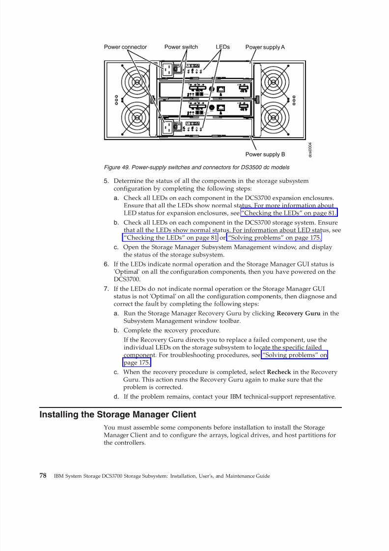
8/9/2019 Installation, User's, And Maintenance
http://slidepdf.com/reader/full/installation-users-and-maintenance 96/262
5. Determine the status of all the components in the storage subsystemconfiguration by completing the following steps:a. Check all LEDs on each component in the DCS3700 expansion enclosures.
Ensure that all the LEDs show normal status. For more information aboutLED status for expansion enclosures, see “Checking the LEDs” on page 81.
b. Check all LEDs on each component in the DCS3700 storage system. Ensurethat all the LEDs show normal status. For information about LED status, see“Checking the LEDs” on page 81 or “Solving problems” on page 175.
c. Open the Storage Manager Subsystem Management window, and displaythe status of the storage subsystem.
6. If the LEDs indicate normal operation and the Storage Manager GUI status is'Optimal' on all the configuration components, then you have powered on theDCS3700.
7. If the LEDs do not indicate normal operation or the Storage Manager GUIstatus is not 'Optimal' on all the configuration components, then diagnose andcorrect the fault by completing the following steps:
a. Run the Storage Manager Recovery Guru by clicking Recovery Guru in theSubsystem Management window toolbar.
b. Complete the recovery procedure.If the Recovery Guru directs you to replace a failed component, use theindividual LEDs on the storage subsystem to locate the specific failedcomponent. For troubleshooting procedures, see “Solving problems” onpage 175.
c. When the recovery procedure is completed, select Recheck in the RecoveryGuru. This action runs the Recovery Guru again to make sure that the
problem is corrected.d. If the problem remains, contact your IBM technical-support representative.
Installing the Storage Manager Client
You must assemble some components before installation to install the StorageManager Client and to configure the arrays, logical drives, and host partitions forthe controllers.
d c s i 0 0 0 4
Lnk Lnk Lnk Lnk
ID/Diag
L nk L nk
Lnk Lnk L nk Ln k
ID/Diag
L nk L nk
ACDC
2
1
I
O
ACDC
2
1
I
O
Power connector Power supply APower switch LEDs
Power supply B
Figure 49. Power-supply switches and connectors for DS3500 dc models
78 IBM System Storage DCS3700 Storage Subsystem: Installation, User's, and Maintenance Guide
8/9/2019 Installation, User's, And Maintenance
http://slidepdf.com/reader/full/installation-users-and-maintenance 97/262
For instructions to install the DS Storage Manager software, see the IBM SystemStorage DS Storage Manager Version 10 Installation and Host Support Guide (for DSStorage Manager V10.77 or earlier) or the IBM System Storage DS Storage ManagerVersion 10.8 Installation and Host Support Guide (for DS Storage Manager V10.83 orlater) for the applicable operating system. The document is in the Documentationfolder on the IBM Support Software DVD. Use this document and the online help toconfigure the arrays, logical drives, and host partitions for the controllers. Follow
the instructions in the operating-system documentation to make the new logicaldrives accessible to the operating system. Do not proceed with the configurationsetup until you have completed the Storage Manager installation.
Assemble any additional items in preparation for software installation. These itemsmight include the following items:v HBA device driversv Controller firmwarev IP addresses for controllers (for out-of-band management only)v Additional documentation for hosts, HBAs, and other storage components
Save the storage subsystem profile before any planned system shutdown or afterany system additions, removals, or modifications (including firmware updates,logical drive creations, storage partitioning definitions, hardware changes, and soon). For instructions to save the storage subsystem profile, see the IBM SystemStorage DS Storage Manager Version 10 Installation and Host Support Guide (for DSStorage Manager V10.77 or earlier) or the IBM System Storage DS Storage ManagerVersion 10.8 Installation and Host Support Guide (for DS Storage Manager V10.83 orlater) for the applicable operating system. Save the profile in a location other thanthe logical drives that are created for the storage subsystem.
Ensure that you read the readme file that is included with the DCS3700 storagesubsystem firmware package (whether the firmware is accessed by the Web or aDVD) for any special requirements or restrictions that apply to that firmware
version.Note: Ensure that you install the Storage Manager event monitoring service toenable continuous monitoring of the status of the storage subsystem. For moreinformation about the importance of this information, see “Monitoring statusthrough software.”
Monitoring status through software
Use the Storage Manager software to monitor the status of the storage subsystem.
Run the software constantly, and check it frequently.
Note: You can monitor only storage subsystems that are within the managementdomain of the Storage Manager. If you have not installed the Storage ManagerEvent Monitor service as part of the storage-management software installation, theStorage Manager Enterprise Management window must remain open. (If you closethe window, you will not receive any alert notifications from the managed storagesubsystems.)
For more information, see the Enterprise Management online help.
Important: For instructions to install the DS Storage Manager software, see theIBM System Storage DS Storage Manager Version 10 Installation and Host Support
Chapter 4. Operating the DCS3700 storage system and expansion enclosure 79
8/9/2019 Installation, User's, And Maintenance
http://slidepdf.com/reader/full/installation-users-and-maintenance 98/262
Guide (for DS Storage Manager V10.77 or earlier) or the IBM System Storage DSStorage Manager Version 10.8 Installation and Host Support Guide (for DS StorageManager V10.83 or later) for the applicable operating system. The document is inthe Documentation folder on the IBM Support Software DVD.
To download the latest version of the Storage Manager software, controllerfirmware, NVSRAM firmware, and the latest ESM firmware, go to
http://www.ibm.com/servers/storage/support/disk/.
The Storage Manager software provides the best way to diagnose and repairstorage-subsystem failures. The software can help you:v Determine the nature of the failurev Locate the failed componentv Determine the recovery procedures to repair the failure
Amber (needs attention) LEDs do not necessarily indicate which component hasfailed or must be replaced or which type of recovery procedure you must perform.In some cases (such as when a drive exceeds its Predictive Failure Analysis [PFA]threshold), the amber LED is not lit. Only the Storage Manager software can detect
the failure.
For example, the recovery procedure for a PFA flag (impending drive failure) on adrive varies depending on the drive status (hot spare, unassigned, RAID level,current logical drive status, and so on). Depending on the circumstances, a PFAflag on a drive can indicate a high risk of data loss (if the drive is in a RAID 0volume) or a minimal risk (if the drive is unassigned). Only the Storage Managersoftware can identify the risk level and provide the necessary recovery procedures.
Note: For PFA flags, the system-error LED and drive status LEDs are not lit, sochecking the LEDs will not notify you of the failure, even if the risk of data loss ishigh.
Attention: Not following the software-recovery procedures can result in data loss.In addition, always replace a failing component as soon as possible to minimizeadditional failures that might occur and cause loss of data access.
Firmware updatesYou must maintain the ESM firmware, controller firmware, drive firmware, and theNVSRAM firmware up-to-date and know the prerequisites, update instructions,download-sequence information, and host I/O restrictions.
Attention: Save the storage subsystem profile before you perform any controlleror ESM firmware upgrades. Save the profile and all configuration (.cfg) files to aserver disk that will remain accessible in the event of a DCS3700 storage
configuration failure. Do not save these files only to a LUN in the storagesubsystem.
Go to http://www.ibm.com/servers/storage/support/disk/ to get the latestupdates.
Ensure that you read the readme files that are included with the firmwarepackages for the most up-to-date information about firmware prerequisites,firmware update instructions, download-sequence information, and host I/Orestrictions, if any. Apply the necessary updates before you configure the storagesubsystem arrays and logical drives. Subscribe to My Support for automatic
80 IBM System Storage DCS3700 Storage Subsystem: Installation, User's, and Maintenance Guide
8/9/2019 Installation, User's, And Maintenance
http://slidepdf.com/reader/full/installation-users-and-maintenance 99/262
notifications of firmware or Storage Manager software updates or any importantinformation about the DCS3700 storage subsystems (see “Receiving productupdates and support notifications” on page 6).
Attention: Failure to observe the limitations, prerequisites, sequences, anddependencies in the readme file might result in a loss of data access.
Unless the readme file contains special requirements for the sequence in which youupgrade firmware, perform firmware upgrades in the following sequence:1. ESM firmware for the expansion enclosures2. Controller firmware
3. Controller NVSRAM4. Drive firmware
Troubleshooting the storage subsystemIBM DS Storage Manager is the best way to monitor the storage subsystem,diagnose a problem, and recover from a hardware failure.
Run the Storage Manager software continuously, and frequently check theconfiguration status.
To check the status of and identify a problem with the storage subsystem, completethe following steps. If a problem has occurred, use the Storage Manager softwareand the LEDs on the storage subsystem to help locate a failed component.1. Open the Subsystem Management window.2. Click the Summary tab, and view the status of the storage subsystem.
3. If any storage subsystem has a 'Needs Attention' status, click Recovery Guruon the toolbar. Perform the procedure in the Recovery Guru to correct theproblem. The Recovery Guru might direct you to replace the failed component.If so, go to step 4.
Attention: If the fault requires you to power-off an enclosure in your storagesubsystem, you might have to cycle the power on the DCS3700 storage systemand all remaining expansion enclosures that are part of the storage subsystem.Contact your IBM technical-support representative before you power-off anyother component of the storage subsystem.
4. If no storage subsystem has a 'Needs Attention' status, then all components areoptimal. Check the LEDs on the front and the rear of the storage enclosure. Agreen LED indicates a normal status; an amber LED indicates a hardware fault.
5. Check if the amber LED is lit. If yes, locate and troubleshoot the failedcomponents. See “Checking the LEDs.” If not, then you have completed thisprocedure. If you are still experiencing a problem with the storage subsystem,create, save, and print a storage subsystem profile, and contact your IBM
technical-support representative for assistance. When the recovery procedure iscompleted, select Recheck in the Recovery Guru to run the Recovery Guruagain to make sure that the problem is corrected.
Checking the LEDs
The LEDs indicate the status of the storage subsystem and components.
Green LEDs indicate a normal operating status; amber LEDs indicate a possiblefailure; a blue LED on a component indicates that it is safe to remove thecomponent.
Chapter 4. Operating the DCS3700 storage system and expansion enclosure 81
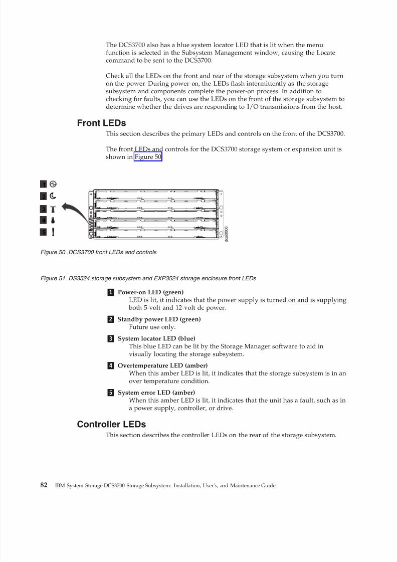
8/9/2019 Installation, User's, And Maintenance
http://slidepdf.com/reader/full/installation-users-and-maintenance 100/262
The DCS3700 also has a blue system locator LED that is lit when the menufunction is selected in the Subsystem Management window, causing the Locatecommand to be sent to the DCS3700.
Check all the LEDs on the front and rear of the storage subsystem when you turnon the power. During power-on, the LEDs flash intermittently as the storagesubsystem and components complete the power-on process. In addition to
checking for faults, you can use the LEDs on the front of the storage subsystem todetermine whether the drives are responding to I/O transmissions from the host.
Front LEDsThis section describes the primary LEDs and controls on the front of the DCS3700.
The front LEDs and controls for the DCS3700 storage system or expansion unit isshown in Figure 50.
1 Power-on LED (green)LED is lit, it indicates that the power supply is turned on and is supplying both 5-volt and 12-volt dc power.
2 Standby power LED (green)Future use only.
3 System locator LED (blue)This blue LED can be lit by the Storage Manager software to aid invisually locating the storage subsystem.
4 Overtemperature LED (amber)When this amber LED is lit, it indicates that the storage subsystem is in anover temperature condition.
5 System error LED (amber)When this amber LED is lit, it indicates that the unit has a fault, such as ina power supply, controller, or drive.
Controller LEDsThis section describes the controller LEDs on the rear of the storage subsystem.
d c s i 0 0 0 6
1
2
3
4
5
Figure 50. DCS3700 front LEDs and controls
Figure 51. DS3524 storage subsystem and EXP3524 storage enclosure front LEDs
82 IBM System Storage DCS3700 Storage Subsystem: Installation, User's, and Maintenance Guide
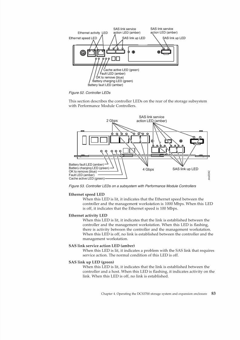
8/9/2019 Installation, User's, And Maintenance
http://slidepdf.com/reader/full/installation-users-and-maintenance 101/262
This section describes the controller LEDs on the rear of the storage subsystemwith Performance Module Controllers.
Ethernet speed LEDWhen this LED is lit, it indicates that the Ethernet speed between thecontroller and the management workstation is 1000 Mbps. When this LEDis off, it indicates that the Ethernet speed is 100 Mbps.
Ethernet activity LEDWhen this LED is lit, it indicates that the link is established between thecontroller and the management workstation. When this LED is flashing,there is activity between the controller and the management workstation.When this LED is off, no link is established between the controller and the
management workstation.SAS link service action LED (amber)
When this LED is lit, it indicates a problem with the SAS link that requiresservice action. The normal condition of this LED is off.
SAS link up LED (green)When this LED is lit, it indicates that the link is established between thecontroller and a host. When this LED is flashing, it indicates activity on thelink. When this LED is off, no link is established.
Figure 52. Controller LEDs
2 Gbps
d c
s i 0 0 4 2
Battery fault LED (amber)Battery charging LED (green)OK to remove (blue)Fault LED (amber)
Cache active LED (green)
4 Gbps
SAS link serviceaction LED (amber)
SAS link up LED
Figure 53. Controller LEDs on a subsystem with Performance Module Controllers
Chapter 4. Operating the DCS3700 storage system and expansion enclosure 83
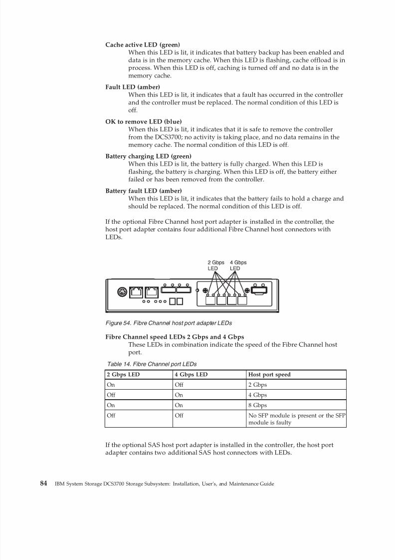
8/9/2019 Installation, User's, And Maintenance
http://slidepdf.com/reader/full/installation-users-and-maintenance 102/262
Cache active LED (green)When this LED is lit, it indicates that battery backup has been enabled anddata is in the memory cache. When this LED is flashing, cache offload is inprocess. When this LED is off, caching is turned off and no data is in thememory cache.
Fault LED (amber)
When this LED is lit, it indicates that a fault has occurred in the controllerand the controller must be replaced. The normal condition of this LED isoff.
OK to remove LED (blue)When this LED is lit, it indicates that it is safe to remove the controllerfrom the DCS3700; no activity is taking place, and no data remains in thememory cache. The normal condition of this LED is off.
Battery charging LED (green)When this LED is lit, the battery is fully charged. When this LED isflashing, the battery is charging. When this LED is off, the battery eitherfailed or has been removed from the controller.
Battery fault LED (amber)
When this LED is lit, it indicates that the battery fails to hold a charge andshould be replaced. The normal condition of this LED is off.
If the optional Fibre Channel host port adapter is installed in the controller, thehost port adapter contains four additional Fibre Channel host connectors withLEDs.
Fibre Channel speed LEDs 2 Gbps and 4 GbpsThese LEDs in combination indicate the speed of the Fibre Channel hostport.
Table 14. Fibre Channel port LEDs
2 Gbps LED 4 Gbps LED Host port speed
On Off 2 Gbps
Off On 4 Gbps
On On 8 Gbps
Off Off No SFP module is present or the SFPmodule is faulty
If the optional SAS host port adapter is installed in the controller, the host portadapter contains two additional SAS host connectors with LEDs.
Figure 54. Fibre Channel host port adapter LEDs
84 IBM System Storage DCS3700 Storage Subsystem: Installation, User's, and Maintenance Guide

8/9/2019 Installation, User's, And Maintenance
http://slidepdf.com/reader/full/installation-users-and-maintenance 103/262
SAS link service action LED (amber)When this LED is lit, it indicates a problem with the SAS link that requiresservice action. The normal condition of this LED is off.
SAS link up LED (green)When this LED is lit, it indicates that the link is established between thecontroller and a host. When this LED is flashing, it indicates activity on thelink. When this LED is off, no link is established.
ESM LEDsThis section describes the ESM LEDS.
Figure 56 shows the LEDs on the ESM.
Link fault LED (amber)When this amber LED is lit, it indicates that the link through the SAS cableis not successful.
Link up LED (green)
When this green LED is lit, it indicates that the link through the SAS cableis successful.
OK to remove LED (blue)This LED is supported only when the EXP3500 is attached to a DS3500controller. Do not remove the ESM unless this blue LED is lit.
Fault LED (amber)When this amber LED is lit, it indicates that the ESM has failed.
Power-on LED (green)When this green LED is lit, it indicates that the ESM is receiving power.
SAS link serviceaction (amber)LED
SAS link up LED
Figure 55. SAS host port adapter LEDs
S
Link fault LED(amber)
Link up LED(green)
OK to remove LED(blue) Fault LED
(amber)
Power-on LED(green)
Link fault LED(amber)
Link up LED(green)
Seven-segmentnumeric display
Figure 56. ESM LEDs
Chapter 4. Operating the DCS3700 storage system and expansion enclosure 85
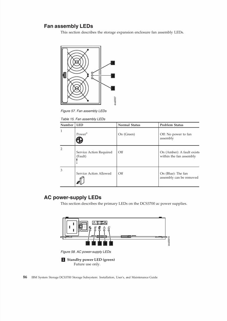
8/9/2019 Installation, User's, And Maintenance
http://slidepdf.com/reader/full/installation-users-and-maintenance 104/262
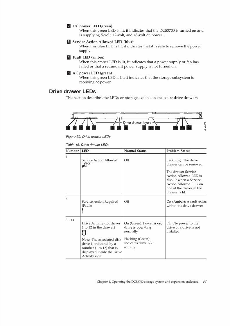
8/9/2019 Installation, User's, And Maintenance
http://slidepdf.com/reader/full/installation-users-and-maintenance 105/262
2 DC power LED (green)When this green LED is lit, it indicates that the DCS3700 is turned on andis supplying 5-volt, 12-volt, and 48-volt dc power.
3 Service Action Allowed LED (blue)When this blue LED is lit, it indicates that it is safe to remove the powersupply.
4 Fault LED (amber)When this amber LED is lit, it indicates that a power supply or fan hasfailed or that a redundant power supply is not turned on.
5 AC power LED (green)When this green LED is lit, it indicates that the storage subsystem isreceiving ac power.
Drive drawer LEDsThis section describes the LEDs on storage expansion enclosure drive drawers.
Table 16. Drive drawer LEDs
Number LED Normal Status Problem Status
1Service Action Allowed
OKOff On (Blue): The drive
drawer can be removed
The drawer ServiceAction Allowed LED isalso lit when a ServiceAction Allowed LED onone of the drives in thedrawer is lit.
2Service Action Required(Fault)
Off On (Amber): A fault existswithin the drive drawer
3 - 14Drive Activity (for drives
1 to 12 in the drawer)
Note: The associated diskdrive is indicated by anumber (1 to 12) that isdisplayed inside the DriveActivity icon.
On (Green): Power is on,
drive is operatingnormally
Flashing (Green):Indicates drive I/Oactivity
Off: No power to the
drive or a drive is notinstalled
d c s i 0 0 0 8
12 1 3 141 3 42 5 6 7 8 109 11
Drive drawer levers
Figure 59. Drive drawer LEDs
Chapter 4. Operating the DCS3700 storage system and expansion enclosure 87
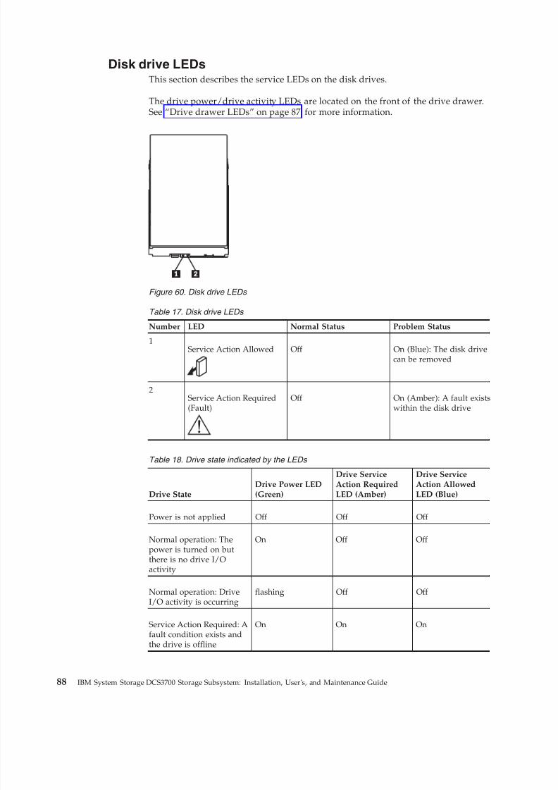
8/9/2019 Installation, User's, And Maintenance
http://slidepdf.com/reader/full/installation-users-and-maintenance 106/262
Disk drive LEDsThis section describes the service LEDs on the disk drives.
The drive power/drive activity LEDs are located on the front of the drive drawer.See “Drive drawer LEDs” on page 87 for more information.
Table 17. Disk drive LEDs
Number LED Normal Status Problem Status
1Service Action Allowed Off On (Blue): The disk drive
can be removed
2Service Action Required(Fault)
Off On (Amber): A fault existswithin the disk drive
Table 18. Drive state indicated by the LEDs
Drive StateDrive Power LED(Green)
Drive ServiceAction RequiredLED (Amber)
Drive ServiceAction AllowedLED (Blue)
Power is not applied Off Off Off
Normal operation: The
power is turned on butthere is no drive I/Oactivity
On Off Off
Normal operation: DriveI/O activity is occurring
flashing Off Off
Service Action Required: Afault condition exists andthe drive is offline
On On On
Figure 60. Disk drive LEDs
88 IBM System Storage DCS3700 Storage Subsystem: Installation, User's, and Maintenance Guide
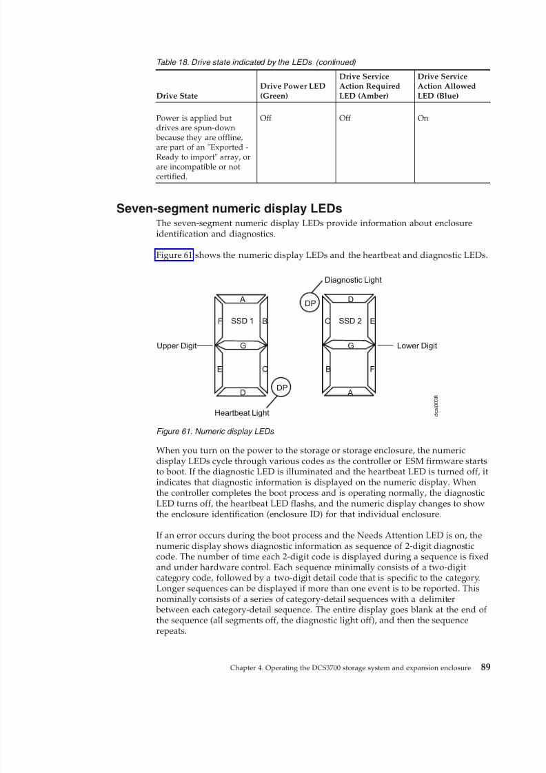
8/9/2019 Installation, User's, And Maintenance
http://slidepdf.com/reader/full/installation-users-and-maintenance 107/262
Table 18. Drive state indicated by the LEDs (continued)
Drive StateDrive Power LED(Green)
Drive ServiceAction RequiredLED (Amber)
Drive ServiceAction AllowedLED (Blue)
Power is applied butdrives are spun-down
because they are offline,are part of an "Exported -Ready to import" array, orare incompatible or notcertified.
Off Off On
Seven-segment numeric display LEDsThe seven-segment numeric display LEDs provide information about enclosureidentification and diagnostics.
Figure 61 shows the numeric display LEDs and the heartbeat and diagnostic LEDs.
When you turn on the power to the storage or storage enclosure, the numericdisplay LEDs cycle through various codes as the controller or ESM firmware startsto boot. If the diagnostic LED is illuminated and the heartbeat LED is turned off, itindicates that diagnostic information is displayed on the numeric display. Whenthe controller completes the boot process and is operating normally, the diagnosticLED turns off, the heartbeat LED flashs, and the numeric display changes to showthe enclosure identification (enclosure ID) for that individual enclosure.
If an error occurs during the boot process and the Needs Attention LED is on, thenumeric display shows diagnostic information as sequence of 2-digit diagnosticcode. The number of time each 2-digit code is displayed during a sequence is fixedand under hardware control. Each sequence minimally consists of a two-digitcategory code, followed by a two-digit detail code that is specific to the category.Longer sequences can be displayed if more than one event is to be reported. Thisnominally consists of a series of category-detail sequences with a delimiter
between each category-detail sequence. The entire display goes blank at the end of the sequence (all segments off, the diagnostic light off), and then the sequencerepeats.
A
D
BF
CE
G
SSD 1
D
A
EC
FB
G
SSD 2
DP
DP
Diagnostic Light
Heartbeat Light
Lower DigitUpper Digit
d c s i 0
0 3 8
Figure 61. Numeric display LEDs
Chapter 4. Operating the DCS3700 storage system and expansion enclosure 89
8/9/2019 Installation, User's, And Maintenance
http://slidepdf.com/reader/full/installation-users-and-maintenance 108/262
For more information about the diagnostic codes and their possible causes, see the"Seven-segment display sequence codes and their causes" section of this document.
Cache memory and cache battery
Cache memory size stores read and write operations in DCS3700 and DCS3700with Performance Module Controllers.
Each storage controller in the DCS3700 storage subsystem contains 2 GB or 4 GB of cache memory to store read and write operations. In a dual controllerconfiguration, both controllers in the DCS3700 must have the same amount of cache memory. For a DCS3700 storage subsystem with Performance ModuleControllers, the cache memory is 6 GB, upgradeable to 12 GB or 24 GB. The
battery unit contains enough charge to back up the cached data in each controllerto a flash drive in the event of a DCS3700 power failure.
Cache memoryThe controller has a cache active LED that indicates the current status of the cache.
The LED is lit when there is data in the cache, and it is off when there is no datain the cache.
If caching is enabled and the cache active LED is not lit during I/O, it indicatesone of the following conditions:v The cache memory from either controller A or controller B has failedv The cache sizes in controller A and controller B are not the samev The battery has failed
Note: Always use the Storage Manager client to check the cache memory settings before you assume that a hardware failure has occurred.
See“Controller LEDs” on page 82 for the location of the cache active LED on acontroller.
Controller cache batteryThe backup battery unit provides power to back up the cache memory of eachcontroller onto flash drives in the event of a power failure.
Each battery unit contains a sealed, rechargeable SMART lithium ion battery.
CAUTION:The battery is a lithium ion battery. To avoid possible explosion, do not burn.Exchange only with the IBM-approved part. Recycle or discard the battery asinstructed by local regulations. In the United States, IBM has a process for thecollection of this battery. For information, call 1-800-426-4333. Have the IBM partnumber for the battery unit available when you call. (C007)
90 IBM System Storage DCS3700 Storage Subsystem: Installation, User's, and Maintenance Guide
8/9/2019 Installation, User's, And Maintenance
http://slidepdf.com/reader/full/installation-users-and-maintenance 109/262
Replace the battery units in the DCS3700 storage system when they are identifiedas failing by the Storage Manager Subsystem Management window, or when the
battery fault LEDs light. See “Controller LEDs” on page 82 for the location of the battery fault LED.
Replace only the battery unit that is indicated as failed by the LEDs or in theStorage Manager Subsystem Management window. In a dual controller
configuration, you do not need to replace both battery units when the Battery faultLEDs indicate that only one battery unit has failed. Each controller has a greenBattery charging LED that indicates the status of the battery unit.v The LED is on when the battery is fully chargedv The LED flashes when the battery is charging or performing a self-testv The LED is off when the battery or the battery charger has failed or is missing
Cache battery learn cycleThe battery performs the learn cycle activity.
The battery performs a learn cycle the first time the storage subsystem is turned
on, and again every eight weeks thereafter, to assess the charge capacity of the battery. If the battery fails the learn cycle or takes too much time to reach fullcharge, the Battery charging LED turns off, the Battery fault LED turns on and theStorage Manager identifies the battery as failed.
The learn cycle takes up to three hours. During this time, the cache will be active if the battery is in optimal condition. If the learn cycle is interrupted, the currentlearn cycle will be terminated and the battery will perform a new learn cycle at thenext scheduled interval (eight weeks from the current learn cycle). A learn cycleinterruption is caused by removing the battery from the controller chassis, resettingthe power to the storage subsystem, or if an storage enclosure or battery overheats.
Data caching starts after the battery is charged to the programmed voltage level,
which occurs when the storage subsystem power is first turned on, when a new battery is installed to replace a failed battery, or when the subsystem power isturned on after months of inactivity.
Attention: Write caching is suspended while a battery pack is either charging orself-testing.
Turning off the storage subsystem
Only in certain situations, you can power off the storage subsystem.
The DCS3700 is designed to run continuously. After you turn it on, do not turn itoff. Turn off the power only in the following situations:v Instructions in a hardware or software procedure require that you turn off the
power.v An IBM technical-support representative instructs you to turn off the power.v A power outage or emergency situation occurs, see “Restoring power after an
unexpected shutdown” on page 94 .
Attention:: Except in an emergency, never turn off the power if any amber (needsattention) LEDs are lit. Correct the fault before you turn off the power. Use theStorage Manager software and the amber LEDs to check the overall status of the
Chapter 4. Operating the DCS3700 storage system and expansion enclosure 91
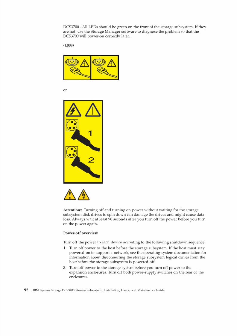
8/9/2019 Installation, User's, And Maintenance
http://slidepdf.com/reader/full/installation-users-and-maintenance 110/262
DCS3700 . All LEDs should be green on the front of the storage subsystem. If theyare not, use the Storage Manager software to diagnose the problem so that theDCS3700 will power-on correctly later.
(L003)
1 2
or
!
1
2
Attention:: Turning off and turning on power without waiting for the storagesubsystem disk drives to spin down can damage the drives and might cause dataloss. Always wait at least 90 seconds after you turn off the power before you turnon the power again.
Power-off overview
Turn off the power to each device according to the following shutdown sequence:
1. Turn off power to the host before the storage subsystem. If the host must staypowered-on to support a network, see the operating-system documentation forinformation about disconnecting the storage subsystem logical drives from thehost before the storage subsystem is powered-off.
2. Turn off power to the storage system before you turn off power to theexpansion enclosures. Turn off both power-supply switches on the rear of theenclosures.
92 IBM System Storage DCS3700 Storage Subsystem: Installation, User's, and Maintenance Guide
8/9/2019 Installation, User's, And Maintenance
http://slidepdf.com/reader/full/installation-users-and-maintenance 111/262
3. Turn off power to other supporting devices (for example, managementstations).
Note: You do not have to perform this step if you are servicing only thestorage subsystem.
To turn off power to one or more components of the storage subsystem for a
planned shutdown, complete the steps in the following procedure. To turn off power for an unplanned shutdown, see“Restoring power after an unexpectedshutdown” on page 94.
Figure 10 on page 15 shows the locations of the power switches on a storagesubsystem.
Before you proceed, use the Storage Manager software to determine the status of the storage subsystem components and special instructions. You might have tocomplete other procedures before you turn off the power.1. Stop all I/O activity to each storage subsystem.2. Determine the status of all storage subsystems components in the
configuration by completing the following steps:a. Check all LEDs on each component in the expansion enclosures. Ensure that
all the LEDs show normal status.b. Check all LEDs on each component in the storage system. Ensure that all
the LEDs show normal status.
c. Review the status of the configuration in the Subsystem Managementwindow by clicking the Summary tab.The status is either Optimal or Needs Attention.
3. If the LEDs do not indicate normal operation or the status on all configurationcomponents is not 'Optimal', diagnose and correct the fault:a. Run the Recovery Guru by clicking Recovery Guru in the toolbar of the
Subsystem Management window.b. If you need to replace a failed component, use the individual LEDs to locatethe failed component.
c. When the recovery procedure is completed, click Recheck in the RecoveryGuru. This action runs the Recovery Guru again to ensure that the problemis corrected.
d. If the problem has not been corrected, contact your IBM technical-supportrepresentative. Do not turn off power until all problems are corrected.
4. If the LEDs indicate normal operation and the status on all configurationcomponents is 'Optimal', check the cache active LED, and ensure that it is off.If the cache active LED is lit, the cache contains data. Wait for the data to clearfrom cache memory before you turn off the power.
5. Check the LEDs of the disk drive drawer to ensure that all drive activity LEDsare off.If one or more LEDs are flashing, it indicates that data is being written to orfrom the drives. Wait for all activity LEDs to stop flashing.
6. Turn off the ac power switch on the rear of the DCS3700 storage system in thestorage subsystem.
Note: Until the power switch on each power supply is turned off, powerremains turned on for both controllers.
Chapter 4. Operating the DCS3700 storage system and expansion enclosure 93
8/9/2019 Installation, User's, And Maintenance
http://slidepdf.com/reader/full/installation-users-and-maintenance 112/262
7. Turn off both power switches on the rear of each storage expansion enclosurein the configuration.
8. After you perform the necessary maintenance procedures, turn on the power,using the procedure in “Powering on the DCS3700” on page 77.
Performing an emergency shutdown
You must perform three steps to shutdown your subsystem in case of emergencies.
Attention: Emergency situations might include fire, flood, extreme weatherconditions, or other hazardous circumstances. If a power outage or emergencysituation occurs, turn off all power switches on all computing equipment. Thishelps to safeguard your equipment from potential damage due to electrical surgeswhen power is restored. If the storage subsystem loses power unexpectedly, itmight be due to a hardware failure in the power system or in the midplane.
To shut down the system during an emergency, complete the following steps:1. If you have time, stop all I/O activity to the storage subsystem by shutting
down the host or disconnecting the storage subsystem logical drives through
the host.2. Check the LEDs. Note down any amber LEDs that are lit so that you can
correct the problem when you turn on the power again.
3. Turn off all power-supply switches, starting with the DCS3700 storage systemfirst and followed by the DCS3700 expansion enclosures. Then, disconnect thepower cables from the storage subsystem.
Restoring power after an unexpected shutdown
You can restore power to the subsystem after an unplanned shutdown but afterensuring that there is no evidence of fire, power, or structural damage.
To restore power to the storage subsystem after an unplanned shutdown, completethe following steps.
DANGER
Never turn on any equipment when there is evidence of fire, water, orstructural damage.
1. After the emergency situation is over or power is restored, check the storagesubsystem for damage.
2. If there is evidence of damage to any of the storage subsystem components,cables, or equipment that is attached to the storage subsystem, do not continuewith this procedure. Contact your IBM technical-support representative for
assistance. Depending on the current service agreements, you might have toreturn the equipment to the factory or local service center for repair.Attention: To avoid potential data loss, ensure that the storage system and theexpansion enclosure power switches are turned off before you reset circuit
breakers in the rack. Resetting circuit breakers after an emergency situationwhile the storage system and the expansion enclosure power switches areturned on can cause data loss, because the configuration components might not
be powered-on in the correct sequence. See “Powering on the DCS3700” onpage 77 for details about the correct power-on sequence.
94 IBM System Storage DCS3700 Storage Subsystem: Installation, User's, and Maintenance Guide
8/9/2019 Installation, User's, And Maintenance
http://slidepdf.com/reader/full/installation-users-and-maintenance 113/262
3. After you check the storage subsystem for damage, ensure that the powerswitches are off; then connect the DCS3700 power cables, if required.
4. Check the system documentation of the hardware devices that you want toturn on and determine the correct startup sequence.
5. Turn on both of the power-supply switches on DCS3700 expansion enclosuresand make sure that no ESM or power-supply fault LEDs are lit before you
power on the DCS3700 storage system.In addition, consider the following items:v The storage subsystem supports simultaneous power-on of the system
components. However, always check the system documentation of thehardware devices that you want to turn on and determine the correct startupsequence.
v A storage subsystem in an optimal state recovers automatically from anunexpected shutdown and unattended simultaneous restoration of power tosystem components. After power is restored, contact your IBMtechnical-support representative if any of the following conditions occur:– The storage subsystem logical drives and arrays do not display in the
Storage Manager graphical user interface.
– The storage subsystem logical drives and arrays do not come online.– The storage subsystem logical drives and arrays seem to be degraded.
6. Turn on both of the power-supply switches on the DCS3700 storage system. See“Solving problems” on page 175.
Recovering from an overheated power supply
You can recover when the power supply on the storage enclosure is overheated.
Each storage enclosure contains two power supplies. Each power supply contains a built-in temperature sensor to prevent the power supply from overheating. Undernormal operating conditions, with an ambient air temperature range of 10°C to
40°C (50°F to 104°F), the fans in the power supplies maintain a suitable operatingtemperature inside the module.
If the internal temperature reaches 65°C (149°F), the power supply shuts downautomatically. If both power supplies shut down because of overheating, thestorage subsystem has no power, and all LEDs are off.
The following factors can cause the power supplies to overheat:v An unusually high room temperaturev Fan failures in the power suppliesv Defective circuitry in a power supplyv Blocked air ventsv Failures in other devices in the configuration or rack
If a fan failure causes overheating, the system-error LED and overtemperatureLEDs on the front bezel are lit. The fault LED on the power supply might also belit.“Checking the LEDs” on page 81 shows the location of the LEDs on theDCS3700.
If the storage subsystem temperature exceeds 45°C (113°F), the storagemanagement software displays a Needs Attention icon in the SubsystemManagement window. If the air temperature inside the rack reaches 65°C (149°F),
Chapter 4. Operating the DCS3700 storage system and expansion enclosure 95
8/9/2019 Installation, User's, And Maintenance
http://slidepdf.com/reader/full/installation-users-and-maintenance 114/262
the power supplies automatically shut down. If event monitoring is enabled andevent notification is configured, the software issues two critical-problemnotifications.v If one power supply shuts down, the storage management software displays a
Needs Attention status in the Subsystem Management window.v If both power supplies shut down, the storage subsystem shuts down, and the
storage management software displays a Not Responding status in theSubsystem Management window.Attention: To prevent damage to the storage subsystem components when thepower supplies automatically shut down, immediately remove all rack panels tohelp reduce the rack air temperature.
To resume normal operation after a power-supply shutdown, complete thefollowing steps:1. Confirm whether you used the procedure in “Troubleshooting the storage
subsystem” on page 81 to ensure that the power supplies have shut down because of an overheating problem.
2. Stop I/O activity to the storage system and all attached expansion enclosures.
3. Take all or some of the following measures to alleviate the overheatingproblem:v Remove all panels from the rack immediately.v Use external fans to cool the area.v Shut down the power to the storage enclosure, using the procedure that is
described in “Performing an emergency shutdown” on page 94.4. Wait for the air in and around the storage subsystem to cool.
After the temperature inside the power supplies drops to below 65°C (149°F),the storage subsystem is capable of power-on recovery without operatorintervention. After the air has cooled, the power supplies should turn onautomatically. If the power supplies restart automatically, the controllers willreset and return to normal operation.
5. If the power supplies restarted automatically, go to step 8.6. If the power supplies did not restart automatically, turn off both power
switches on the DCS3700 storage system (see Figure 10 on page 15 and thenpower-off all connected DCS3700 expansion enclosures. Wait for a minute andthen turn on power to all connected DCS3700 expansion enclosures.While the expansion enclosure powers on, the LEDs on the front and the rearof the enclosure flash intermittently. Depending on the configuration, theexpansion enclosure can take between 20 seconds and several minutes topower on.
7. Turn on both power switches on the rear of the DCS3700 storage system.The storage system can take up to 10 minutes to power on and up to 15
minutes for the battery self-test to be completed. During this time, the LEDson the front and the rear of the storage system flash intermittently.8. Check the LEDs on the front and rear of the storage system and each attached
expansion enclosure (a green LED indicates a normal status; an amber LEDindicates a hardware fault); then, check the array status in the SubsystemManagement window.v Open the Subsystem Management window for the storage subsystem.v Click the Summary tab and review the status of the configuration.
The status is either Optimal or Needs Attention.
96 IBM System Storage DCS3700 Storage Subsystem: Installation, User's, and Maintenance Guide
8/9/2019 Installation, User's, And Maintenance
http://slidepdf.com/reader/full/installation-users-and-maintenance 115/262
9. If any module (controller, power supply, ESM) does not display a green statusLED, or if the status for any module component is not 'Optimal', diagnose andcorrect the fault.
a. To run the Recovery Guru, click Recovery Guru in the toolbar in theSubsystem Management window.
b. If you need to replace a failed component, locate and troubleshoot that
component. See “Checking the LEDs” on page 81.c. When the procedure is completed, select Recheck in the Recovery Guru.This runs the Recovery Guru again to ensure that the problem is corrected.
d. If the problem remains, contact your IBM technical-support representative.
10. Replace the bezel on the storage enclosure, if applicable.
Chapter 4. Operating the DCS3700 storage system and expansion enclosure 97

8/9/2019 Installation, User's, And Maintenance
http://slidepdf.com/reader/full/installation-users-and-maintenance 116/262
98 IBM System Storage DCS3700 Storage Subsystem: Installation, User's, and Maintenance Guide
8/9/2019 Installation, User's, And Maintenance
http://slidepdf.com/reader/full/installation-users-and-maintenance 117/262
Chapter 5. Replacing components
Replacing components
This section contains information about replacing components or installing optionaldevices in the DCS3700 storage system and DCS3700 expansion unit.
Before you replace any component, ensure that you wear an anti-static wrist strap.
Attention: To avoid overheating the storage enclosure and causing damage to itscomponents, replace failed parts within 10 minutes, unless otherwise indicated.The Recovery Guru in the Storage Manager software identifies failed parts.
Do not remove the failed part from the storage enclosure until you:v Review the replacement procedure for the failed part in this guide.v Locate screw drivers or any other hand tools that you might need to replace the
failed part.v Receive the replacement part and are ready to install it in the enclosure.
Service Action Allowed LED
Blue Service Action Allowed LED indicator is useful to replace components.
Each controller, ESM, fan assembly, disk drive, disk drive drawer, and powersupply has a blue Service Action Allowed LED. The purpose of the Service ActionAllowed LED is to help ensure that a component is not removed before it is safe todo so. Do not remove any component unless the component Service ActionAllowed LED is lit.
Attention
If you remove a controller, ESM, disk drive, disk drive drawer, or power supplywhen the Service Action Allowed LED is not lit, a loss of data availability canresult. If an amber LED is lit and the associated Service Action Allowed LED is notlit, you must run additional diagnostics before you can remove the indicatedcomponent. Use the Recovery Guru instructions in the Subsystem Managementwindow or see the applicable component replacement instructions in this chapterfor the additional diagnostics that are required in this case.
The Service Action Allowed LED automatically turns on or off as conditionschange. Wait for at least two minutes after you replace a component for the storage
subsystem to recognize the new component and update the LED status. In mostcases, when a single component fails, the Service Action Allowed LED stays litwhen the amber LED is lit for the component.
Working with controllers
This section describes how to remove a controller, remove and install a cover,install a controller, replace a controller, and dispose of the system-board battery onthe controller.
Before you begin, ensure that you wear an anti-static wrist strap.
© Copyright IBM Corp. 2011, 2013 99
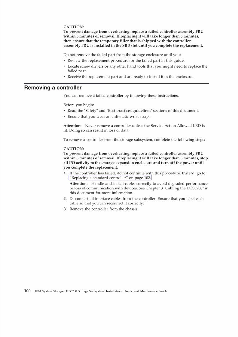
8/9/2019 Installation, User's, And Maintenance
http://slidepdf.com/reader/full/installation-users-and-maintenance 118/262
CAUTION:To prevent damage from overheating, replace a failed controller assembly FRUwithin 5 minutes of removal. If replacing it will take longer than 5 minutes,then ensure that the temporary filler that is shipped with the controllerassembly FRU is installed in the SBB slot until you complete the replacement.
Do not remove the failed part from the storage enclosure until you:v Review the replacement procedure for the failed part in this guide.v Locate screw drivers or any other hand tools that you might need to replace the
failed part.v Receive the replacement part and are ready to install it in the enclosure.
Removing a controller
You can remove a failed controller by following these instructions.
Before you begin:v Read the "Safety" and "Best practices guidelines" sections of this document.v
Ensure that you wear an anti-static wrist strap.Attention: Never remove a controller unless the Service Action Allowed LED islit. Doing so can result in loss of data.
To remove a controller from the storage subsystem, complete the following steps:
CAUTION:To prevent damage from overheating, replace a failed controller assembly FRUwithin 5 minutes of removal. If replacing it will take longer than 5 minutes, stopall I/O activity to the storage expansion enclosure and turn off the power untilyou complete the replacement.
1. If the controller has failed, do not continue with this procedure. Instead, go to
“Replacing a standard controller” on page 102.Attention: Handle and install cables correctly to avoid degraded performanceor loss of communication with devices. See Chapter 3 "Cabling the DCS3700" inthis document for more information.
2. Disconnect all interface cables from the controller. Ensure that you label eachcable so that you can reconnect it correctly.
3. Remove the controller from the chassis.
100 IBM System Storage DCS3700 Storage Subsystem: Installation, User's, and Maintenance Guide
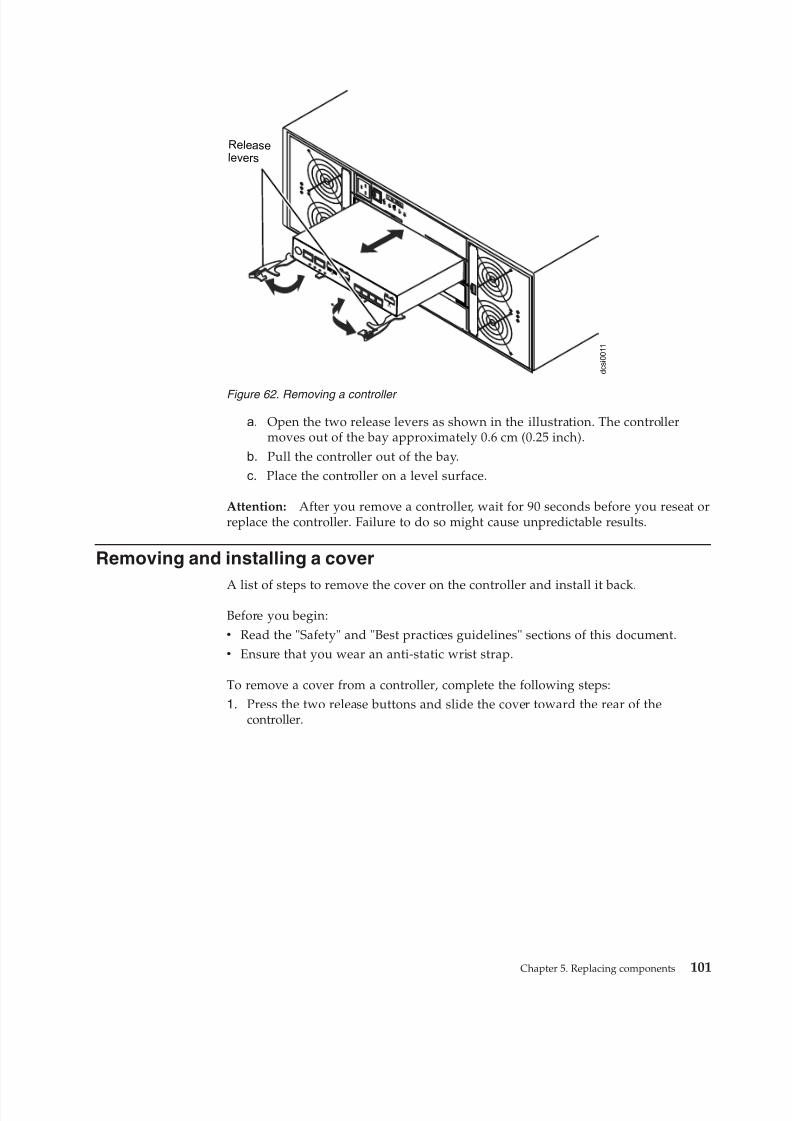
8/9/2019 Installation, User's, And Maintenance
http://slidepdf.com/reader/full/installation-users-and-maintenance 119/262
a. Open the two release levers as shown in the illustration. The controllermoves out of the bay approximately 0.6 cm (0.25 inch).
b. Pull the controller out of the bay.c. Place the controller on a level surface.
Attention: After you remove a controller, wait for 90 seconds before you reseat orreplace the controller. Failure to do so might cause unpredictable results.
Removing and installing a cover
A list of steps to remove the cover on the controller and install it back.Before you begin:v Read the "Safety" and "Best practices guidelines" sections of this document.v Ensure that you wear an anti-static wrist strap.
To remove a cover from a controller, complete the following steps:1. Press the two release buttons and slide the cover toward the rear of the
controller.
AC
DC
2
1
I
O
d c s i 0 0 1 1
Release
lever s
Figure 62. Removing a controller
Chapter 5. Replacing components 101
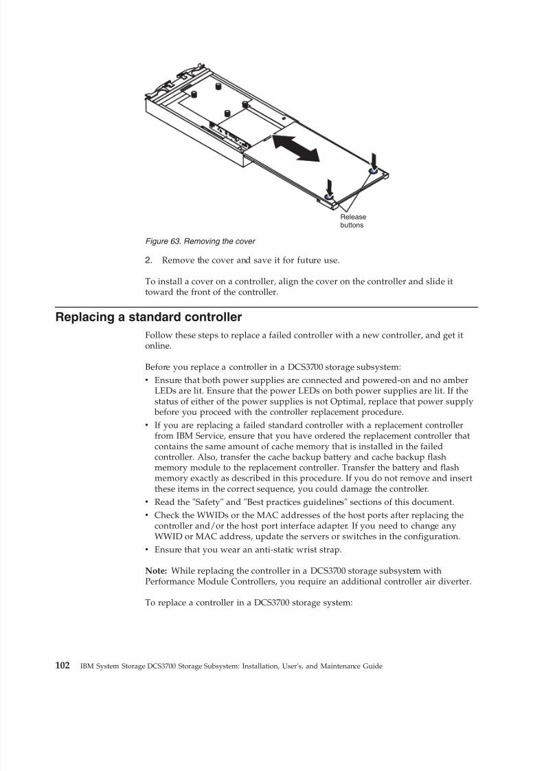
8/9/2019 Installation, User's, And Maintenance
http://slidepdf.com/reader/full/installation-users-and-maintenance 120/262
2. Remove the cover and save it for future use.
To install a cover on a controller, align the cover on the controller and slide ittoward the front of the controller.
Replacing a standard controller
Follow these steps to replace a failed controller with a new controller, and get itonline.
Before you replace a controller in a DCS3700 storage subsystem:v Ensure that both power supplies are connected and powered-on and no amber
LEDs are lit. Ensure that the power LEDs on both power supplies are lit. If the
status of either of the power supplies is not Optimal, replace that power supply before you proceed with the controller replacement procedure.v If you are replacing a failed standard controller with a replacement controller
from IBM Service, ensure that you have ordered the replacement controller thatcontains the same amount of cache memory that is installed in the failedcontroller. Also, transfer the cache backup battery and cache backup flashmemory module to the replacement controller. Transfer the battery and flashmemory exactly as described in this procedure. If you do not remove and insertthese items in the correct sequence, you could damage the controller.
v Read the "Safety" and "Best practices guidelines" sections of this document.v Check the WWIDs or the MAC addresses of the host ports after replacing the
controller and/or the host port interface adapter. If you need to change any
WWID or MAC address, update the servers or switches in the configuration.v Ensure that you wear an anti-static wrist strap.
Note: While replacing the controller in a DCS3700 storage subsystem withPerformance Module Controllers, you require an additional controller air diverter.
To replace a controller in a DCS3700 storage system:
Releasebuttons
Figure 63. Removing the cover
102 IBM System Storage DCS3700 Storage Subsystem: Installation, User's, and Maintenance Guide
8/9/2019 Installation, User's, And Maintenance
http://slidepdf.com/reader/full/installation-users-and-maintenance 121/262
CAUTION:To avoid overheating the storage enclosure and causing damage to itscomponents, replace failed parts within 10 minutes unless directed otherwise.The Recovery Guru in the Storage Manager software identifies failed parts.
1. Use the Storage Manager software to print a storage subsystem profile.2. Move logical drive ownership to the other controller. If the controller that you
are replacing has failed but is still operating, move the failed controller to theOffline state.Attention: Never remove a controller unless the OK to remove LED is lit.Doing so can result in a loss of data.
3. Locate the failed controller by checking the amber LEDs on the controllers inthe storage system.
4. If the OK to remove LED is not lit, another component might require attention before you remove the controller. Use the Recovery Guru in the SubsystemManagement window to identify and correct any additional failures. If thereare none, proceed with step 5 to replace the controller.Attention: Static electricity can damage the storage subsystem and otherelectronic devices. To avoid damage, keep static-sensitive devices in their
static-protective packages until you are ready to install them.5. Unpack the new controller. Save all packing materials in case you have to
return the new controller.6. Determine whether the replacement controller will be controller A or
controller B (controller A is installed in slot SBB A; controller B is installed inslot SBB B), and then paste the controller labels for host ports and driveexpansion ports to the replacement controller. The controller labels andinstructions are included with the replacement controller. Ensure that thelabels are aligned correctly and do not cover any connectors or LEDs.Attention: Handle and install cables correctly to avoid degradedperformance or loss of communication with devices. See Chapter 3 "Cablingthe DCS3700" for more information.
7. Disconnect all attached interface cables from the failed controller. Be sure tolabel each cable so that you can reconnect it correctly to the new controller.
8. Remove the controller from the chassis
Chapter 5. Replacing components 103
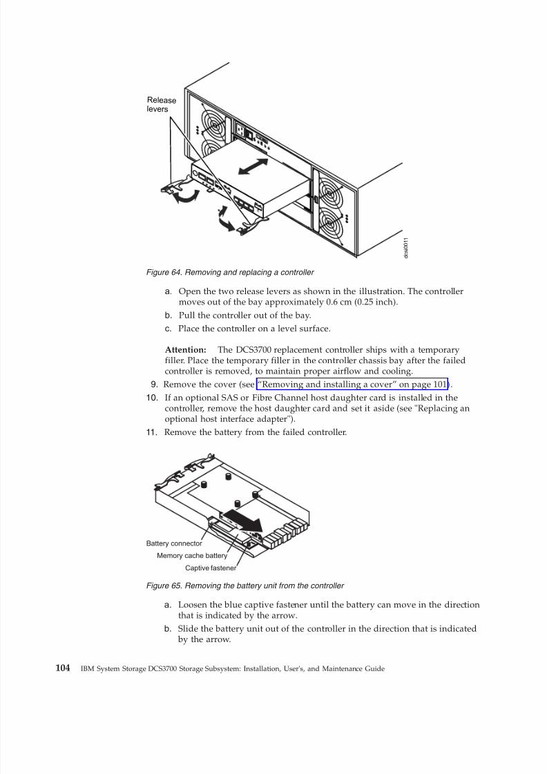
8/9/2019 Installation, User's, And Maintenance
http://slidepdf.com/reader/full/installation-users-and-maintenance 122/262
a. Open the two release levers as shown in the illustration. The controllermoves out of the bay approximately 0.6 cm (0.25 inch).
b. Pull the controller out of the bay.c. Place the controller on a level surface.
Attention: The DCS3700 replacement controller ships with a temporaryfiller. Place the temporary filler in the controller chassis bay after the failedcontroller is removed, to maintain proper airflow and cooling.
9. Remove the cover (see “Removing and installing a cover” on page 101).
10. If an optional SAS or Fibre Channel host daughter card is installed in the
controller, remove the host daughter card and set it aside (see "Replacing anoptional host interface adapter").
11. Remove the battery from the failed controller.
a. Loosen the blue captive fastener until the battery can move in the directionthat is indicated by the arrow.
b. Slide the battery unit out of the controller in the direction that is indicated by the arrow.
AC
DC
2
1
I
O
d c s i 0 0 1 1
Release
lever s
Figure 64. Removing and replacing a controller
Battery connector
Captive fastener
Memory cache battery
Figure 65. Removing the battery unit from the controller
104 IBM System Storage DCS3700 Storage Subsystem: Installation, User's, and Maintenance Guide
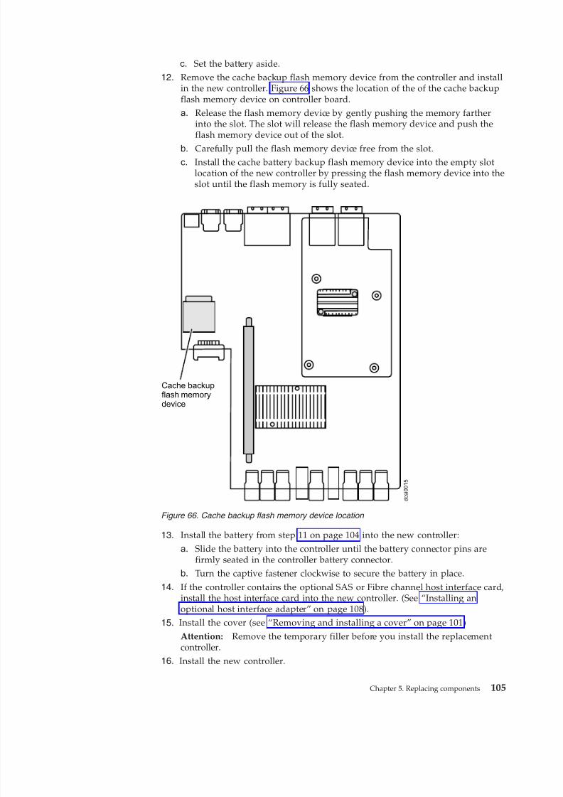
8/9/2019 Installation, User's, And Maintenance
http://slidepdf.com/reader/full/installation-users-and-maintenance 123/262
c. Set the battery aside.12. Remove the cache backup flash memory device from the controller and install
in the new controller. Figure 66 shows the location of the of the cache backupflash memory device on controller board.a. Release the flash memory device by gently pushing the memory farther
into the slot. The slot will release the flash memory device and push the
flash memory device out of the slot.b. Carefully pull the flash memory device free from the slot.c. Install the cache battery backup flash memory device into the empty slot
location of the new controller by pressing the flash memory device into theslot until the flash memory is fully seated.
13. Install the battery from step 11 on page 104 into the new controller:
a. Slide the battery into the controller until the battery connector pins are
firmly seated in the controller battery connector.b. Turn the captive fastener clockwise to secure the battery in place.
14. If the controller contains the optional SAS or Fibre channel host interface card,install the host interface card into the new controller. (See “Installing anoptional host interface adapter” on page 108).
15. Install the cover (see “Removing and installing a cover” on page 101)Attention: Remove the temporary filler before you install the replacementcontroller.
16. Install the new controller.
d c s i 0 0 1 5
Cache backupflash memorydevice
Figure 66. Cache backup flash memory device location
Chapter 5. Replacing components 105
8/9/2019 Installation, User's, And Maintenance
http://slidepdf.com/reader/full/installation-users-and-maintenance 124/262
a. Ensure that the release levers on the controller are in the open position.b. Slide the controller into the bay until it stops.
c. Push the release levers to the closed position.
17. Connect the cables that you disconnected in step 7 on page 103.18. Wait up to 5 minutes for the Storage Manager software to recognize the new
controller.
19. Complete any remaining Recovery Guru procedures for controllerreplacement.
20. Check the LEDs on the new controller to ensure that the controller is fullyoperational.
21. Use the Subsystem Management window to check the status of allcomponents in the storage subsystem.v If the new controller is online and the Subsystem Management window
indicates normal operation, go to step 25.v If the new controller is online and the Subsystem Management window
indicates a problem status, go to the "Troubleshooting" section of thisdocument.
v
If the new controller is offline, continue with step 22.22. If the newly inserted controller is in an offline state, see the Storage Manager
online help for instructions on bringing the controller online. If necessary,open the Subsystem Management window and place the controller online;select the offline controller and click Advanced > Recovery > Place controlleronline.
23. Check the state of the LEDs on the newly inserted controller. For moreinformation, see the "Controller LEDs" section of this document. You can alsouse the Subsystem Management window to identify any new faults.
24. If any storage subsystems has a fault (Needs Attention) status, click RecoveryGuru in the Subsystem Management window toolbar, and complete therecovery procedure. If the problem remains, contact your IBM
technical-support representative.25. If the storage subsystems have no fault, use the Storage Manager software to
print a new storage subsystem profile.26. Check the WWIDs or the MAC addresses of the host ports after replacing the
controller and/or the host port interface adapter. If you need to change anyWWID or MAC address, update the servers or switches in the configuration.
Note: You might have to reboot your system to remove the LUNs informationthat is associated with the WWID of the controller that you removed.
Removing and disposing of the system-board lithium battery
You must take these precautions while replacing a battery and know the batterytype which you must replace, and also the procedure to replace and dispose off theused battery.
Before you begin, ensure that you wear an anti-static wrist strap.
When you disassemble the storage subsystem for disposal, use the information inthis section to locate, remove, and dispose of the lithium batteries that are on thesystem boards in controller A and controller B.
Statement 2
106 IBM System Storage DCS3700 Storage Subsystem: Installation, User's, and Maintenance Guide
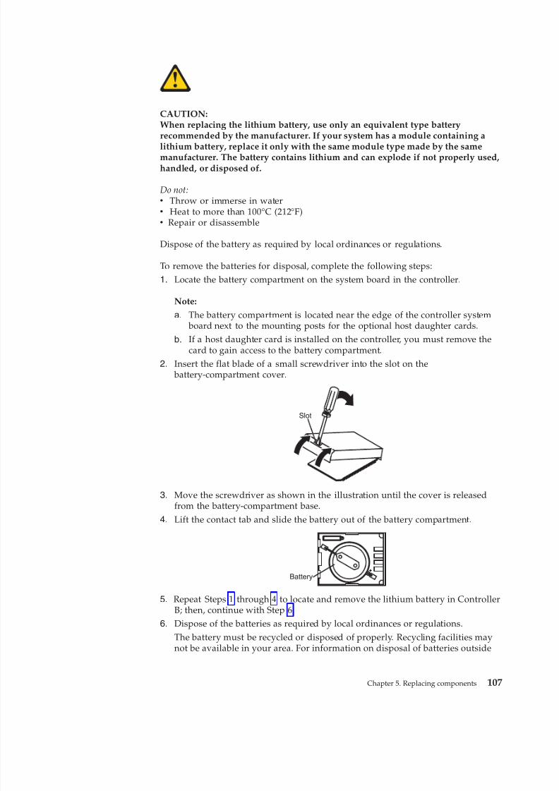
8/9/2019 Installation, User's, And Maintenance
http://slidepdf.com/reader/full/installation-users-and-maintenance 125/262
CAUTION:When replacing the lithium battery, use only an equivalent type battery
recommended by the manufacturer. If your system has a module containing alithium battery, replace it only with the same module type made by the samemanufacturer. The battery contains lithium and can explode if not properly used,handled, or disposed of.
Do not:v Throw or immerse in waterv Heat to more than 100°C (212°F)v Repair or disassemble
Dispose of the battery as required by local ordinances or regulations.
To remove the batteries for disposal, complete the following steps:
1. Locate the battery compartment on the system board in the controller.
Note:
a. The battery compartment is located near the edge of the controller system board next to the mounting posts for the optional host daughter cards.
b. If a host daughter card is installed on the controller, you must remove thecard to gain access to the battery compartment.
2. Insert the flat blade of a small screwdriver into the slot on the battery-compartment cover.
Slot
3. Move the screwdriver as shown in the illustration until the cover is releasedfrom the battery-compartment base.
4. Lift the contact tab and slide the battery out of the battery compartment.
Battery
5. Repeat Steps 1 through 4 to locate and remove the lithium battery in ControllerB; then, continue with Step 6.
6. Dispose of the batteries as required by local ordinances or regulations.The battery must be recycled or disposed of properly. Recycling facilities maynot be available in your area. For information on disposal of batteries outside
Chapter 5. Replacing components 107
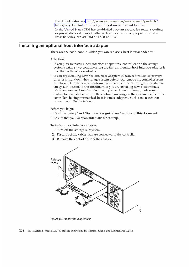
8/9/2019 Installation, User's, And Maintenance
http://slidepdf.com/reader/full/installation-users-and-maintenance 126/262
the United States, see http://www.ibm.com/ibm/environment/products/ batteryrecycle.shtml or contact your local waste disposal facility.In the United States, IBM has established a return process for reuse, recycling,or proper disposal of used batteries. For information on proper disposal of these batteries, contact IBM at 1-800-426-4333.
Installing an optional host interface adapterThese are the conditions in which you can replace a host interface adapter.
Attention:
v If you plan to install a host interface adapter in a controller and the storagesystem contains two controllers, ensure that an identical host interface adapter isinstalled in the other controller.
v If you are installing new host interface adapters in both controllers, to preventdata loss, shut down the storage system before you remove the controller fromthe chassis. For the correct shutdown sequence, see the "Turning off the storagesubsystem" section of this document. If you are installing new host interfaceadapters, you need to schedule time to power down the storage subsystem.
Failure to upgrade both controllers before powering on the system results in thecontrollers having mismatched host interface adapters. Such a mismatch cancause a controller lock-down.
Before you begin:v Read the "Safety" and "Best practices guidelines" sections of this document.v Ensure that you wear an anti-static wrist strap.
To install a host interface adapter:1. Turn off the storage subsystem.
2. Disconnect the cables that are connected to the controller.
3. Remove the controller from the chassis.
AC
DC
2
1
I
O
d c s i 0 0 1 1
Release
lever s
Figure 67. Removing a controller
108 IBM System Storage DCS3700 Storage Subsystem: Installation, User's, and Maintenance Guide
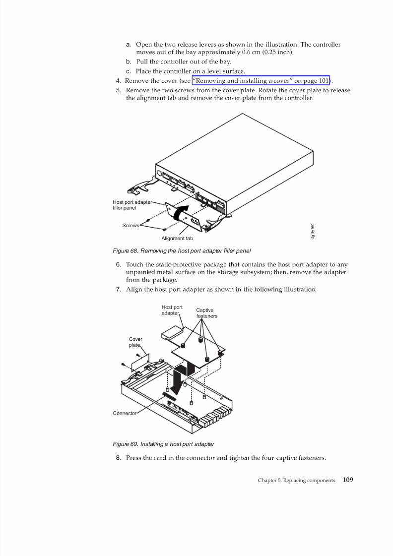
8/9/2019 Installation, User's, And Maintenance
http://slidepdf.com/reader/full/installation-users-and-maintenance 127/262
a. Open the two release levers as shown in the illustration. The controllermoves out of the bay approximately 0.6 cm (0.25 inch).
b. Pull the controller out of the bay.
c. Place the controller on a level surface.4. Remove the cover (see “Removing and installing a cover” on page 101).5. Remove the two screws from the cover plate. Rotate the cover plate to release
the alignment tab and remove the cover plate from the controller.
6. Touch the static-protective package that contains the host port adapter to anyunpainted metal surface on the storage subsystem; then, remove the adapterfrom the package.
7. Align the host port adapter as shown in the following illustration:
8. Press the card in the connector and tighten the four captive fasteners.
Host port adapter filler panel
Screws
Alignment tab d g 1 f y 1 6 0
Figure 68. Removing the host port adapter filler panel
Host portadapter
Captivefasteners
Cover plate
Connector
Figure 69. Installing a host port adapter
Chapter 5. Replacing components 109
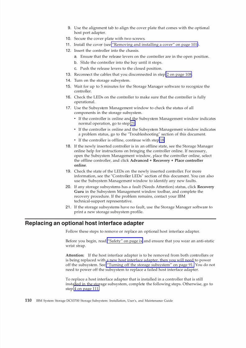
8/9/2019 Installation, User's, And Maintenance
http://slidepdf.com/reader/full/installation-users-and-maintenance 128/262
9. Use the alignment tab to align the cover plate that comes with the optionalhost port adapter.
10. Secure the cover plate with two screws.
11. Install the cover (see “Removing and installing a cover” on page 101).12. Insert the controller into the chassis.
a. Ensure that the release levers on the controller are in the open position.
b. Slide the controller into the bay until it stops.c. Push the release levers to the closed position.
13. Reconnect the cables that you disconnected in step 2 on page 108.
14. Turn on the storage subsystem.
15. Wait for up to 5 minutes for the Storage Manager software to recognize thecontroller.
16. Check the LEDs on the controller to make sure that the controller is fullyoperational.
17. Use the Subsystem Management window to check the status of allcomponents in the storage subsystem.v If the controller is online and the Subsystem Management window indicates
normal operation, go to step 21.v If the controller is online and the Subsystem Management window indicates
a problem status, go to the "Troubleshooting" section of this document.v If the controller is offline, continue with step 18.
18. If the newly inserted controller is in an offline state, see the Storage Manageronline help for instructions on bringing the controller online. If necessary,open the Subsystem Management window, place the controller online, selectthe offline controller, and click Advanced → Recovery → Place controlleronline.
19. Check the state of the LEDs on the newly inserted controller. For moreinformation, see the "Controller LEDs" section of this document. You can also
use the Subsystem Management window to identify any new faults.20. If any storage subsystems has a fault (Needs Attention) status, click RecoveryGuru in the Subsystem Management window toolbar, and complete therecovery procedure. If the problem remains, contact your IBMtechnical-support representative.
21. If the storage subsystems have no fault, use the Storage Manager software toprint a new storage subsystem profile.
Replacing an optional host interface adapter
Follow these steps to remove or replace an optional host interface adapter.
Before you begin, read “Safety” on page ix and ensure that you wear an anti-staticwrist strap.
Attention: If the host interface adapter is to be removed from both controllers oris being replaced with a new host interface adapter, then you will need to poweroff the subsystem. See “Turning off the storage subsystem” on page 91. You do notneed to power off the subsystem to replace a failed host interface adapter.
To replace a host interface adapter that is installed in a controller that is stillinstalled in the storage subsystem, complete the following steps. Otherwise, go tostep 4 on page 111.
110 IBM System Storage DCS3700 Storage Subsystem: Installation, User's, and Maintenance Guide
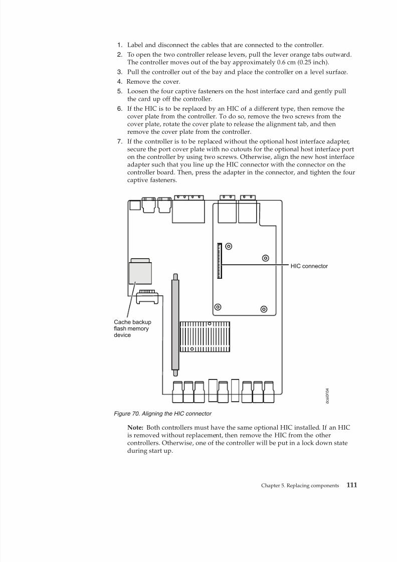
8/9/2019 Installation, User's, And Maintenance
http://slidepdf.com/reader/full/installation-users-and-maintenance 129/262
1. Label and disconnect the cables that are connected to the controller.2. To open the two controller release levers, pull the lever orange tabs outward.
The controller moves out of the bay approximately 0.6 cm (0.25 inch).
3. Pull the controller out of the bay and place the controller on a level surface.4. Remove the cover.5. Loosen the four captive fasteners on the host interface card and gently pull
the card up off the controller.6. If the HIC is to be replaced by an HIC of a different type, then remove the
cover plate from the controller. To do so, remove the two screws from thecover plate, rotate the cover plate to release the alignment tab, and thenremove the cover plate from the controller.
7. If the controller is to be replaced without the optional host interface adapter,secure the port cover plate with no cutouts for the optional host interface porton the controller by using two screws. Otherwise, align the new host interfaceadapter such that you line up the HIC connector with the connector on thecontroller board. Then, press the adapter in the connector, and tighten the fourcaptive fasteners.
Note: Both controllers must have the same optional HIC installed. If an HICis removed without replacement, then remove the HIC from the othercontrollers. Otherwise, one of the controller will be put in a lock down stateduring start up.
d c s i 0 0
3 4
Cache backupflash memorydevice
HIC connector
Figure 70. Aligning the HIC connector
Chapter 5. Replacing components 111
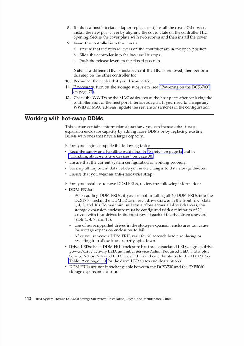
8/9/2019 Installation, User's, And Maintenance
http://slidepdf.com/reader/full/installation-users-and-maintenance 130/262
8. If this is a host interface adapter replacement, install the cover. Otherwise,install the new port cover by aligning the cover plate on the controller HICopening. Secure the cover plate with two screws and then install the cover.
9. Insert the controller into the chassis.a. Ensure that the release levers on the controller are in the open position.b. Slide the controller into the bay until it stops.
c. Push the release levers to the closed position.
Note: If a different HIC is installed or if the HIC is removed, then performthis step on the other controller too.
10. Reconnect the cables that you disconnected.
11. If necessary, turn on the storage subsystem (see “Powering on the DCS3700”on page 77).
12. Check the WWIDs or the MAC addresses of the host ports after replacing thecontroller and/or the host port interface adapter. If you need to change anyWWID or MAC address, update the servers or switches in the configuration.
Working with hot-swap DDMsThis section contains information about how you can increase the storageexpansion enclosure capacity by adding more DDMs or by replacing existingDDMs with ones that have a larger capacity.
Before you begin, complete the following tasks:v Read the safety and handling guidelines in “Safety” on page ix and in
“Handling static-sensitive devices” on page 30.v Ensure that the current system configuration is working properly.v Back up all important data before you make changes to data storage devices.v Ensure that you wear an anti-static wrist strap.
Before you install or remove DDM FRUs, review the following information:v DDM FRUs:
– When adding DDM FRUs, if you are not installing all 60 DDM FRUs into theDCS3700, install the DDM FRUs in each drive drawer in the front row (slots1, 4, 7, and 10). To maintain uniform airflow across all drive drawers, thestorage expansion enclosure must be configured with a minimum of 20drives, with four drives in the front row of each of the five drive drawers(slots 1, 4, 7, and 10).
– Use of non-supported drives in the storage expansion enclosures can causethe storage expansion enclosures to fail.
– After you remove a DDM FRU, wait for 90 seconds before replacing or
reseating it to allow it to properly spin down.v Drive LEDs: Each DDM FRU enclosure has three associated LEDs, a green drive
power/drive activity LED, an amber Service Action Required LED, and a blueService Action Allowed LED. These LEDs indicate the status for that DDM. SeeTable 19 on page 113 for the drive LED states and descriptions.
v DDM FRUs are not interchangeable between the DCS3700 and the EXP5060storage expansion enclosure.
112 IBM System Storage DCS3700 Storage Subsystem: Installation, User's, and Maintenance Guide
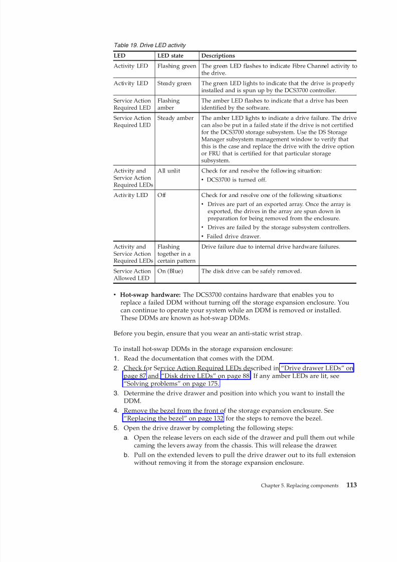
8/9/2019 Installation, User's, And Maintenance
http://slidepdf.com/reader/full/installation-users-and-maintenance 131/262
Table 19. Drive LED activity
LED LED state Descriptions
Activity LED Flashing green The green LED flashes to indicate Fibre Channel activity tothe drive.
Activity LED Steady green The green LED lights to indicate that the drive is properlyinstalled and is spun up by the DCS3700 controller.
Service ActionRequired LED
Flashingamber
The amber LED flashes to indicate that a drive has beenidentified by the software.
Service ActionRequired LED
Steady amber The amber LED lights to indicate a drive failure. The drivecan also be put in a failed state if the drive is not certifiedfor the DCS3700 storage subsystem. Use the DS StorageManager subsystem management window to verify thatthis is the case and replace the drive with the drive optionor FRU that is certified for that particular storagesubsystem.
Activity andService ActionRequired LEDs
All unlit Check for and resolve the following situation:
v DCS3700 is turned off.
Activity LED Off Check for and resolve one of the following situations:v Drives are part of an exported array. Once the array is
exported, the drives in the array are spun down inpreparation for being removed from the enclosure.
v Drives are failed by the storage subsystem controllers.
v Failed drive drawer.
Activity andService ActionRequired LEDs
Flashingtogether in acertain pattern
Drive failure due to internal drive hardware failures.
Service ActionAllowed LED
On (Blue) The disk drive can be safely removed.
v Hot-swap hardware: The DCS3700 contains hardware that enables you toreplace a failed DDM without turning off the storage expansion enclosure. Youcan continue to operate your system while an DDM is removed or installed.These DDMs are known as hot-swap DDMs.
Before you begin, ensure that you wear an anti-static wrist strap.
To install hot-swap DDMs in the storage expansion enclosure:1. Read the documentation that comes with the DDM.
2. Check for Service Action Required LEDs described in “Drive drawer LEDs” onpage 87 and “Disk drive LEDs” on page 88. If any amber LEDs are lit, see“Solving problems” on page 175.
3. Determine the drive drawer and position into which you want to install theDDM.
4. Remove the bezel from the front of the storage expansion enclosure. See“Replacing the bezel” on page 132 for the steps to remove the bezel.
5. Open the drive drawer by completing the following steps:
a. Open the release levers on each side of the drawer and pull them out whilecaming the levers away from the chassis. This will release the drawer.
b. Pull on the extended levers to pull the drive drawer out to its full extensionwithout removing it from the storage expansion enclosure.
Chapter 5. Replacing components 113
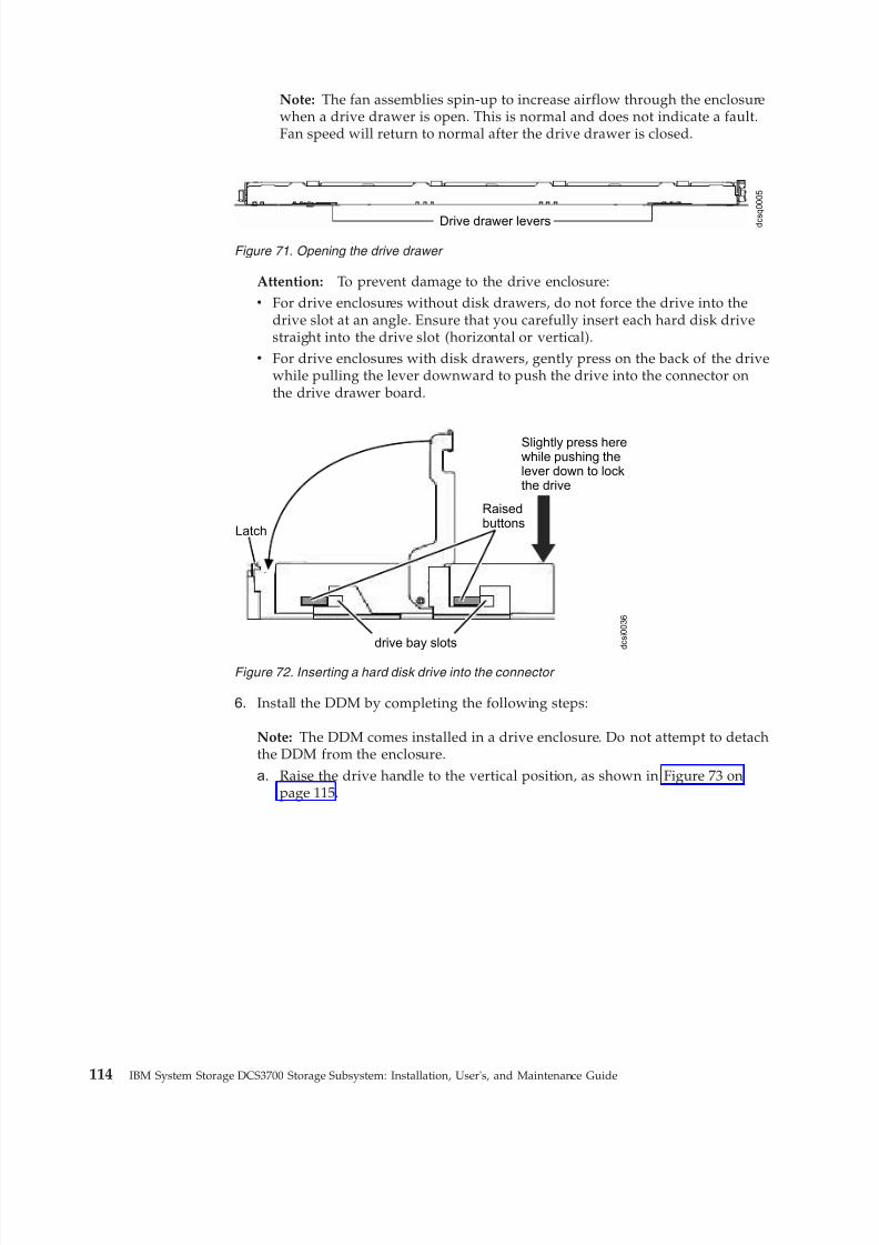
8/9/2019 Installation, User's, And Maintenance
http://slidepdf.com/reader/full/installation-users-and-maintenance 132/262
Note: The fan assemblies spin-up to increase airflow through the enclosurewhen a drive drawer is open. This is normal and does not indicate a fault.Fan speed will return to normal after the drive drawer is closed.
Attention: To prevent damage to the drive enclosure:v For drive enclosures without disk drawers, do not force the drive into the
drive slot at an angle. Ensure that you carefully insert each hard disk drivestraight into the drive slot (horizontal or vertical).
v For drive enclosures with disk drawers, gently press on the back of the drivewhile pulling the lever downward to push the drive into the connector onthe drive drawer board.
6. Install the DDM by completing the following steps:
Note: The DDM comes installed in a drive enclosure. Do not attempt to detachthe DDM from the enclosure.
a. Raise the drive handle to the vertical position, as shown in Figure 73 onpage 115.
Drive drawer levers d c s
q 0 0 0 5
Figure 71. Opening the drive drawer
Latch
drive bay slots
Raisedbuttons
Slightly press herewhile pushing thelever down to lockthe drive
d c s i 0 0 3 6
Figure 72. Inserting a hard disk drive into the connector
114 IBM System Storage DCS3700 Storage Subsystem: Installation, User's, and Maintenance Guide
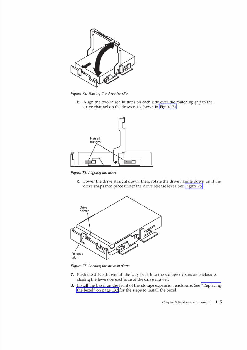
8/9/2019 Installation, User's, And Maintenance
http://slidepdf.com/reader/full/installation-users-and-maintenance 133/262
b. Align the two raised buttons on each side over the matching gap in thedrive channel on the drawer, as shown in Figure 74.
c. Lower the drive straight down; then, rotate the drive handle down until thedrive snaps into place under the drive release lever. See Figure 75.
7. Push the drive drawer all the way back into the storage expansion enclosure,closing the levers on each side of the drive drawer.
8. Install the bezel on the front of the storage expansion enclosure. See “Replacingthe bezel” on page 132 for the steps to install the bezel.
Figure 73. Raising the drive handle
Raisedbuttons
Figure 74. Aligning the drive
Drivehandle
Releaselatch
Figure 75. Locking the drive in place
Chapter 5. Replacing components 115
8/9/2019 Installation, User's, And Maintenance
http://slidepdf.com/reader/full/installation-users-and-maintenance 134/262
Installing hot-swap hard disk drivesWith the exception of the DCS3700 storage subsystem initial power on, you shouldadd DDMs while the storage expansion enclosure is turned on and running.
Attention: After you remove a DDM FRU, wait for 90 seconds before replacing orreseating it to allow it to properly spin down.
Replacing hot-swap hard disk drivesFollow these steps to replace hard disk drives.
DDM problems include any malfunctions that delay, interrupt, or preventsuccessful I/O activity between the hosts and the DDMs in the storage expansionenclosure. This includes transmission problems between the controllers, the ESMs,and the DDMs. This section explains how to replace a failed DDM.
Note: If you want to remove a DDM that is not in a failed or bypass state, use theDS Storage Manager client program either to place the DDM in a failed state or toplace the array that is associated with the DDM (or DDMs) in an offline state
before you remove it from the enclosure.Attention: Failure to replace the DDMs in their correct drawer and positionmight result in loss of data. If you are replacing a DDM that is part of a configuredarray and logical drive, ensure that you install the replacement DDM in the correctdrawer and position.
Before you begin, ensure that you wear an anti-static wrist strap.
To replace a hot-swap DDM:
1. Use the Storage Management client software to print a new storage systemprofile.
2. Determine the location of the DDM that you want to remove.Attention: Never hot-swap an DDM FRU when its associated green activityLED is flashing. Hot-swap an DDM FRU only when its associated blue ServiceAction Allowed LED is lit.
3. Put on anti-static protection.
4. Remove the bezel from the front of the storage enclosure. See “Replacing the bezel” on page 132 for the steps to remove the bezel.
5. Open the drive drawer by completing the following steps:a. Release the levers on each side of the drawer by pulling both levers away
from the enclosure.
b. Pull on the extended levers and cam them outward until they stop. Thenpull the drive drawer out to its full extension without removing it fromthe storage expansion enclosure.
Note: The fan assemblies spin-up to increase airflow through the enclosurewhen a drive drawer is open. This is normal and does not indicate a fault.Fan speed will return to normal after the drive drawer is closed.
6. Remove the DDM by completing the following steps:
a. Press the drive release lever and raise the drive handle to the verticalposition.
b. Wait for 90 seconds to allow the drive to properly spin down and thestorage subsystem controller to properly recognize that an DDM isremoved from the configuration.
116 IBM System Storage DCS3700 Storage Subsystem: Installation, User's, and Maintenance Guide
8/9/2019 Installation, User's, And Maintenance
http://slidepdf.com/reader/full/installation-users-and-maintenance 135/262
c. Ensure that there is proper identification (such as a label) on the DDMFRU, and then lift the drive up and remove it from the drive drawer.
7. Unpack the new DDM. Save all packing material in case you need to return it.
8. Install the new DDM FRU by completing the following steps:
Note: The DDM is installed in a drive enclosure. Do not attempt to detach the
DDM from the enclosure.a. Raise the drive handle to the vertical position.b. Align the two raised buttons on each side over the matching gap in the
drive channel on the drawer.
c. Lower the drive straight down; then, rotate the drive handle down untilthe drive snaps into place under the drive release lever.
9. Push the drive drawer all the way back into the storage expansion enclosure,closing the levers on each side of the drive drawer.
10. Check the DDM LEDs for the following:v When an DDM is ready for use, the green Activity LED lights and the
amber Fault LED is off.v
If the amber Fault LED lights and is not flashing (the Service ActionAllowed LED might also be lit), remove the DDM from the unit and wait90 seconds; then, install the DDM again. If the problem persists, use the DSStorage Manager to verify the drive state and contact IBM support if necessary.
v If the Service Action Allowed LED is lit and the Service Action RequiredLED is not lit, use the DS Storage Manager to check the drive state. Thedrive might be part of an exported array - ready for import, and also might
be incompatible or uncertified. Use the Recovery Guru to diagnose theproblem.
11. Use the DS Storage Manager subsystem management window to verify thatthe DDM is shown in the Storage Subsystem Management window.
12. Install the bezel on the front of the storage expansion enclosure. See“Replacing the bezel” on page 132 for the steps to install the bezel.
Replacing multiple DDMsThis section contains guidelines for upgrading the DDMs in the storage expansionenclosure.
Read the software documentation and this entire section to determine whether youshould use this procedure, use a modified version of this procedure, or use adifferent procedure that is provided by your operating system.
Note: Instructions that are provided with the software should supersede anythingstated in this document.
Before you begin, ensure that you wear an anti-static wrist strap.
Methods for upgrading DDMs are as follows:v Replacing all the DDMs at the same time
This method requires that you back up the data on the affected DDMs and thenturn off the DCS3700 storage subsystem.Attention: Turn off the DCS3700 storage system before you turn off theDCS3700 expansion enclosure.
Chapter 5. Replacing components 117
8/9/2019 Installation, User's, And Maintenance
http://slidepdf.com/reader/full/installation-users-and-maintenance 136/262
After replacing all the DDMs, you must reconfigure the new DDMs and restoredata from backup. See the procedure in “Replacing all DDMs at the same time.”This is the safest way to exchange DDMs without losing data. However, thismethod might take a long time to complete because of the backup,reconfiguration, and restoration processes. In addition, other users are not ableto use the storage subsystem (or any storage expansion enclosures attached tothe storage subsystem) until you finish the procedure. You must use this methodon RAID 0 logical drives.
v Replacing the DDMs one at a time
In this method, you manually fail each DDM, replace it, and wait for the systemto restore data to the new DDM before installing the next DDM. After youinstall the new DDMs, you can configure them to make the additional DDMspace available. See the procedure in “Replacing the drives one at a time” onpage 120.Using this method, you can replace the DDMs while the DCS3700 storagesubsystem is running, eliminating the down time that is required if you replaceall of them at once. However, this method is more risky because you can losedata if the drive restoration or storage subsystem reconfiguration process fails.In addition, the reconstruction process might take a long time. This methodworks only on redundant logical drives (RAID 1, 3, 5, or 6). You cannot use thismethod with any drives containing RAID 0 logical drives.Consider backing up your data if you use this method. This safeguards yourdata if the restoration and reconfiguration process fails or the new DDMmalfunctions.
The method you use depends on the following considerations:v Which method most closely matches the recommended drive upgrade procedure
that is provided in the operating system or the storage-management softwaredocumentation.
v Which RAID level is used on the affected drives. (RAID 0 requires you toreplace all the drives at the same time.)
v How much downtime is acceptable as you swap the DDMs.v How many DDMs exist in an array. Replacing DDMs one at a time is better
suited for arrays consisting of 3 to 5 DDMs. If you have more than 10 DDMs,consider replacing all of them at the same time.
v How much risk of losing data is acceptable. Because the array will be in adegraded state during the RAID array reconstruction and copyback process asresult of replacing an DDM in the array, any new DDM failure will cause thearray to fail (causing a loss of data availability and even a loss of data). Theduration of the reconstruction and copyback process can be quite long,depending on the size of the RAID array.
v How extensive are the changes to the data while the array is in a degraded state
during the RAID array reconstruction and copyback process as result of replacing an DDM in the array. The more extensive the data changes, the morework that will need to be performed to restore the data in the event that thearray failed because of an additional DDM failed while the array is in degradedstate.
Replacing all DDMs at the same timeUse this procedure to replace all DDMs at the same time.
You must use this method if you are upgrading DDMs containing RAID 0 logicaldrives. All the data currently on the DDMs is lost when you replace them;
118 IBM System Storage DCS3700 Storage Subsystem: Installation, User's, and Maintenance Guide
8/9/2019 Installation, User's, And Maintenance
http://slidepdf.com/reader/full/installation-users-and-maintenance 137/262
therefore, you must back up all data that is currently on the DDMs. This procedurealso requires you to turn off the DCS3700 storage subsystem, which makes thestorage subsystem inaccessible to other users.
Before you begin, review the following:v The information in “Replacing multiple DDMs” on page 117, particularly the
paragraphs that discuss the differences between the two possible upgradeprocedures
v The information in your software documentation regarding DDM upgrades andinstallation
v The documentation that comes with the new DDMsRead all precautionary notes, kit instructions, and other information. Kitinstructions often contain the most current information regarding the DDMs andtheir installation, plus upgrade or servicing procedures. Compare the kitinstructions with this procedure to determine if you need to modify thisprocedure.
To replace all the DDMs at the same time, perform the following steps:
1. Use the DS Storage Manager software to check the status of the DCS3700.Correct any problems that are reported.2. Perform a complete backup of the DDMs that you are replacing.
You need the backup to restore data on the DDMs later in this procedure.Attention: When you handle static-sensitive devices, take precautions toavoid damage from static electricity. For details about handling static-sensitivedevices, see “Handling static-sensitive devices” on page 30.
3. Unpack the new DDMs.Set the DDMs on a dry, level surface away from magnetic fields. Save thepacking material and documentation in case you need to return them.
4. Complete the following steps:
a. Stop all I/O activity to the storage subsystem and attached storageexpansion enclosures. Make sure of the following:1) All of the green Drive activity LEDs on the front of the storage
subsystem are not flashing.
2) The Cache active LEDs are off. Refer to “Checking the LEDs” on page81 for the location of the Cache active LEDs.
b. If applicable, use the operating system software to disconnect the storagesubsystem logical drives from the host before you power off the storagesubsystem.
Attention: To turn off all power to the storage subsystem, you must turn off both power-supply switches and disconnect both power cords. Use the
procedure in step 5 for the proper shutdown sequence.5. Turn off the power to each device based on the following shutdown sequence:a. Turn off power to the host before you turn off power to the storage
subsystem. If the host must stay powered on to support an existingnetwork, see the operating system documentation for information aboutdisconnecting the storage subsystem logical drives from the host before thestorage subsystem is powered off.
b. Turn off power to the DCS3700 storage system before you power off theDCS3700 expansion enclosure. Turn off both power supply switches on the
back of the storage subsystem.
Chapter 5. Replacing components 119
8/9/2019 Installation, User's, And Maintenance
http://slidepdf.com/reader/full/installation-users-and-maintenance 138/262
c. Turn off power to other supporting devices (for example, managementstations, Fibre Channel switches, or Ethernet switches).
6. Use the procedures in “Replacing hot-swap hard disk drives” on page 116 toremove the DDMs that you want to replace. Use the procedures in “Installinghot-swap hard disk drives” on page 116 to install the new DDMs into theDCS3700.
7. After you install all the new DDMs, check the system documentation for thehardware devices that you intend to power on, and then determine the properstartup sequence. Use the following power-on sequence, where applicable:a. Turn on the power to the supporting devices (for example, Ethernet
switches and management stations) before you turn off power to thestorage subsystem.
b. You must turn on the expansion enclosures before the storage system. Thecontrollers might not recognize the correct configuration if the drives arepowered up after the storage subsystem.
c. Turn on the power to the storage system; then restart or turn on the powerto the host.
8. Turn on the power to each device, based on the power-on sequence in step 7.
To turn on power to the DCS3700 storage system and expansion enclosures,turn on the power-supply switches on the back of the enclosures. You mustturn on both power-supply switches to take advantage of the redundantpower supplies.
9. Check the green Drive activity LEDs and the amber Drive fault LEDs abovethe new drive FRUs.Ensure that the Drive activity LEDs are on and the Drive fault LEDs are off.
Note: The Drive fault LEDs might flash intermittently while the DDMs spinup.v If the Drive activity LED is off, the DDM FRU might not be installed
correctly. Remove the DDM FRU, wait for 30 seconds, and then reinstall it.
v If the Drive fault LED stays on or the Drive activity LED stays off, the newDDM might be faulty. See the DS Storage Manager software for problemdetermination.
10. Use the DS Storage Manager software to configure the new DDMs. See the DSStorage Manager software online Help for detailed instructions.
11. Restore the data from backup to all the DDMs.
Replacing the drives one at a timeUse this procedure to replace all the drives one at a time.
You cannot use this procedure on RAID 0 logical drives (use the procedure in“Replacing all DDMs at the same time” on page 118).
Note: If your storage subsystem has hot spares assigned, you might want tounassign the hot spares while you perform this procedure. If you do unassign thehot spares, reconstruction might start on the hot spare before you insert the newdrive. The data on the new DDM is still rebuilt, but the process takes longer foreach DDM. Remember to reassign the hot spares when you are finished with thisprocedure.Attention: After you remove a DDM FRU, wait for 90 seconds before replacing orreseating it to allow it to properly spin down.
Before you begin, review the following:
120 IBM System Storage DCS3700 Storage Subsystem: Installation, User's, and Maintenance Guide

8/9/2019 Installation, User's, And Maintenance
http://slidepdf.com/reader/full/installation-users-and-maintenance 139/262
v “Replacing multiple DDMs” on page 117, particularly the paragraphs thatdiscuss the differences between the two possible upgrade procedures
v Your software documentation regarding drive upgrades and installationv The documentation that comes with the new drives
Read all precautionary notes, kit instructions, and other information. Kitinstructions often contain the most current information regarding the drives and
their installation, plus upgrade or servicing procedures. Compare the kitinstructions with this procedure to determine if you need to modify thisprocedure.
To replace the DDMs one at a time, perform the following steps:
1. Use the DS Storage Manager software to check the status of the unit. Correctany problems that are reported.
2. Back up the data in the arrays and logical drives that are configured using theDDMs that you are replacing.Attention: When you handle static-sensitive devices, take precautions toavoid damage from static electricity. For details about handling static-sensitivedevices, see “Handling static-sensitive devices” on page 30.
3. Unpack the new DDMs.Set the DDMs on a dry, level surface away from magnetic fields. Save thepacking material and documentation in case you need to return them.
4. Use the DS Storage Manager software to ensure that the array that was definedusing these DDMs is in optimal (not degraded) state before manually failingthe first DDM you want to replace. If the array is in degraded state, use therecovery procedures to bring the array into the optimal state.Ensure that you fail only one DDM. The software status should display a failedstatus for the appropriate DDM. The amber Drive fault LED (on the front bezel
below the DDM) should be on.Attention: Removing the wrong DDM can cause data loss. Ensure that youremove only the failed DDM FRU. The Drive fault LED below the failed DDMFRU should be on.
If you remove an active DDM accidentally, wait for 30 seconds and thenreinstall it. Because you failed two DDMs in a RAID array, the array might bemarked failed by the controller. This array will not be available to the host forI/O. See the DS Storage Manager software for further recovery instructions. Donot attempt to replace any DDMs until the array is brought back to optimalstate.
5. Use the procedures in “Replacing hot-swap hard disk drives” on page 116 toremove the failed drive. Use the procedures in “Installing hot-swap hard diskdrives” on page 116 to install the new DDMs into the DCS3700.The new DDM automatically reconstructs the data after you install it in the
drive slot.During data reconstruction, the amber Drive fault LED might come on for afew minutes, then turn off when the green Drive activity LED begins flashing.A flashing Drive activity LED indicates that data reconstruction is in progress.
Note: If your storage subsystem has active hot spares, data might not startcopying to the new DDM until the data is reconstructed on the hot spare. Thisincreases the time that is required to complete the procedure.
6. Check the green Drive activity LED and the amber Drive fault LED above thenew DDM FRUs.
Chapter 5. Replacing components 121
8/9/2019 Installation, User's, And Maintenance
http://slidepdf.com/reader/full/installation-users-and-maintenance 140/262
Ensure that the Drive activity LEDs are on and the Drive fault LEDs are off.
Note: The Drive fault LEDs might flash intermittently while the DDMs spinup.v If the Drive activity LED is off, the DDM FRU might not be installed
correctly. Remove the DDM FRU, wait for 30 seconds, and then reinstall it.v
If the Drive fault LED stays on or the Drive activity LED stays off, the newDDM might be faulty. See the DS Storage Manager software for problemdetermination.
7. Use the DS Storage Manager software to monitor the status of the new DDMand the progress of the data reconstruction. Wait for data reconstruction tofinish. (The Drive activity LED stops flashing.)
Note: The Drive activity LED will continue to flash after reconstruction isfinished if there is I/O activity to that DDM. In that case, use the host softwareto determine if the data reconstruction is finished.
8. When reconstruction is finished on the new DDM, repeat step 4 on page 121through step 7 for each additional DDM that you want to install.
9. Use the DS Storage Manager software to configure the additional space on thenew DDMs.
Replacing an ac power supply
You must take these precautions while replacing an AC power supply and followthe steps to replace the power supply.
(L003)1 2
or
122 IBM System Storage DCS3700 Storage Subsystem: Installation, User's, and Maintenance Guide
8/9/2019 Installation, User's, And Maintenance
http://slidepdf.com/reader/full/installation-users-and-maintenance 141/262
!
1
2
The power supplies are customer replaceable units (CRUs) and do not requirepreventive maintenance. Use only the supported power supplies for the storagesubsystem.
Each power supply has a built-in sensor that detects the following conditions:v Over-voltagev Over-currentv Overheated power supply
If any of these conditions occurs, one or both power supplies will shut down. If the power remains off (does not automatically restart), make sure that theenvironment is optimal (no overheating has occurred, all electrical receptacles are
working, and so on).
If both power supplies fail or if the power supplies cannot maintain an internaltemperature below 65°C (149°F), the power supplies will automatically shut down(an overtemperature condition). If this occurs, you must cool the storage subsystemand restart it.
Attention: Do not remove the failed power supply until you have thereplacement power supply. When you do remove the failed power supply, be sureto install the second power supply within 5 minutes to prevent any overheatingdue to the interruption to the air flow that cools the storage subsystem.
Do not run the storage subsystem without adequate ventilation and cooling,
because it might cause damage to the internal components and circuitry.
Before you begin:v Use the Storage Manager software to print a storage system profile, if required.v Read the "Safety" section of this document.v Ensure that you wear an anti-static wrist strap.
Chapter 5. Replacing components 123

8/9/2019 Installation, User's, And Maintenance
http://slidepdf.com/reader/full/installation-users-and-maintenance 142/262
DANGER
When working on or around the system, observe the following precautions:
Electrical voltage and current from power, telephone, and communicationcables are hazardous. To avoid a shock hazard:
v Connect power to this unit only with the provided power cord. Do not use
the provided power cord for any other product.v Do not open or service any power supply assembly.
v Do not connect or disconnect any cables or perform installation,maintenance, or reconfiguration of this product during an electrical storm.
v The product might be equipped with multiple power cords. To remove allhazardous voltages, disconnect all power cords.
v Connect all power cords to a properly wired and grounded electrical outlet.Ensure that the outlet supplies proper voltage and phase rotation accordingto the system rating plate.
v Connect any equipment that will be attached to this product to properlywired outlets.
v When possible, use one hand only to connect or disconnect signal cables.
v Never turn on any equipment when there is evidence of fire, water, orstructural damage.
v Disconnect the attached power cords, telecommunications systems,networks, and modems before you open the device covers, unlessinstructed otherwise in the installation and configuration procedures.
v Connect and disconnect cables as described in the following procedureswhen installing, moving, or opening covers on this product or attacheddevices.
To disconnect:
1. Turn off everything (unless instructed otherwise).
2. Remove the power cords from the outlets.
3. Remove the signal cables from the connectors.
4. Remove all cables from the devices.
To connect:
1. Turn off everything (unless instructed otherwise).
2. Attach all cables to the devices.
3. Attach the signal cables to the connectors.
4. Attach the power cords to the outlets.
5. Turn on the devices.
(D005a)
To replace a power supply, complete the following steps.
124 IBM System Storage DCS3700 Storage Subsystem: Installation, User's, and Maintenance Guide
8/9/2019 Installation, User's, And Maintenance
http://slidepdf.com/reader/full/installation-users-and-maintenance 143/262
CAUTION:To prevent damage to the storage subsystem components from overheating,replace a failed power supply within 5 minutes of removal. If replacing it willtake longer than 5 minutes, stop all I/O activity to the storage subsystem andturn off the power until you complete the replacement. Do not remove the failedpower supply from the storage enclosure until you:
v Review the replacement procedure in this section.
v Have the replacement power supply and are ready to install it in theenclosure.
(L001)
1. Ensure that you run the Recovery Guru to identify the failed component.
2. Unpack the new power supply. Save all packing material in case you have toreturn the failed power supply.
3. Turn off the power switch on the new unit.
4. Check the fault LED to locate the failed power supply. If a fault is detected,the amber fault LED is lit.
5. Ensure that the Service Action Allowed LED is lit. Do not remove the power
supply if the LED is off. For more information about the Service ActionAllowed LED, see “Service Action Allowed LED” on page 99.6. Turn off the power switch and disconnect the power cord from the failed
power supply.
7. Remove the power supply from the bay.
Chapter 5. Replacing components 125
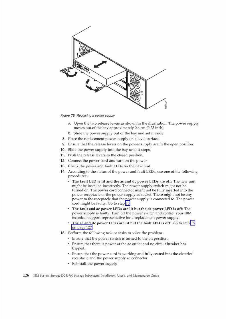
8/9/2019 Installation, User's, And Maintenance
http://slidepdf.com/reader/full/installation-users-and-maintenance 144/262
a. Open the two release levers as shown in the illustration. The power supplymoves out of the bay approximately 0.6 cm (0.25 inch).
b. Slide the power supply out of the bay and set it aside.8. Place the replacement power supply on a level surface.
9. Ensure that the release levers on the power supply are in the open position.
10. Slide the power supply into the bay until it stops.11. Push the release levers to the closed position.
12. Connect the power cord and turn on the power.
13. Check the power and fault LEDs on the new unit.14. According to the status of the power and fault LEDs, use one of the followingprocedures:v The fault LED is lit and the ac and dc power LEDs are off: The new unit
might be installed incorrectly. The power-supply switch might not beturned on. The power cord connector might not be fully inserted into thepower receptacle or the power-supply ac socket. There might not be anypower to the receptacle that the power supply is connected to. The powercord might be faulty. Go to step 15.
v The fault and ac power LEDs are lit but the dc power LED is off: Thepower supply is faulty. Turn off the power switch and contact your IBMtechnical-support representative for a replacement power supply.
v The ac and dc power LEDs are lit but the fault LED is off: Go to step 16on page 127.
15. Perform the following task or tasks to solve the problem:v Ensure that the power switch is turned to the on position.v Ensure that there is power at the ac outlet and no circuit breaker has
tripped.v Ensure that the power cord is working and fully seated into the electrical
receptacle and the power supply ac connector.v Reinstall the power supply.
AC
DC
2
1
I
O
d c s i 0 0 2 4
Figure 76. Replacing a power supply
126 IBM System Storage DCS3700 Storage Subsystem: Installation, User's, and Maintenance Guide
8/9/2019 Installation, User's, And Maintenance
http://slidepdf.com/reader/full/installation-users-and-maintenance 145/262
If these tasks do not solve the problem, contact your IBM technical-supportrepresentative.
16. Complete any remaining Recovery Guru procedures.
17. If any amber LEDs are lit on any of the components of the storage subsystem,click Recovery Guru in the Subsystem Management window toolbar andcomplete the recovery procedure. If a problem is still indicated, contact your
IBM technical-support representative.18. If the status of each component is 'Optimal', create, save, and print a newstorage subsystem profile.
Replacing a battery
Follow these steps to replace the failed cache battery.
The controller in the DCS3700 storage system contains a rechargeable battery backup unit that provides power to back up the cache memory onto flash memoryin the event of a power failure. Each battery unit contains a sealed, rechargeableSMART lithium ion battery. The cache battery is the only replaceable battery in thestorage subsystem.
Use the following procedure if the Storage Manager software instructs you toreplace the battery because the current battery has failed. You can also use theStorage Manager software to check the status of the battery. Because write-cachingis disabled when the battery fails, replace the failed battery as soon as possible tominimize any performance impact due to the disabling of the write-cachingfunction.
Attention: When you handle static-sensitive devices, take precautions to avoiddamage from static electricity. For details about handling static-sensitive devices,see the safety information in the prolog of this document.
Attention: To avoid overheating the storage enclosure and causing damage to itscomponents, replace failed parts within 10 minutes. The Recovery Guru in theStorage Manager software identifies failed parts.
Do not remove the failed part from the storage enclosure until you:v Review the replacement procedure for the failed part in this guide.v Locate screw drivers or any other hand tools that you might need to replace the
failed part.v Receive the replacement part and are ready to install it in the enclosure.
Before you begin:v Use the Storage Manager software to print a storage subsystem profile.v
Read the "Safety" section of this document.v Ensure that you wear an anti-static wrist strap.
To replace a battery unit:1. Locate the controller that contains the failed battery unit.2. Remove the controller from the chassis.
Chapter 5. Replacing components 127
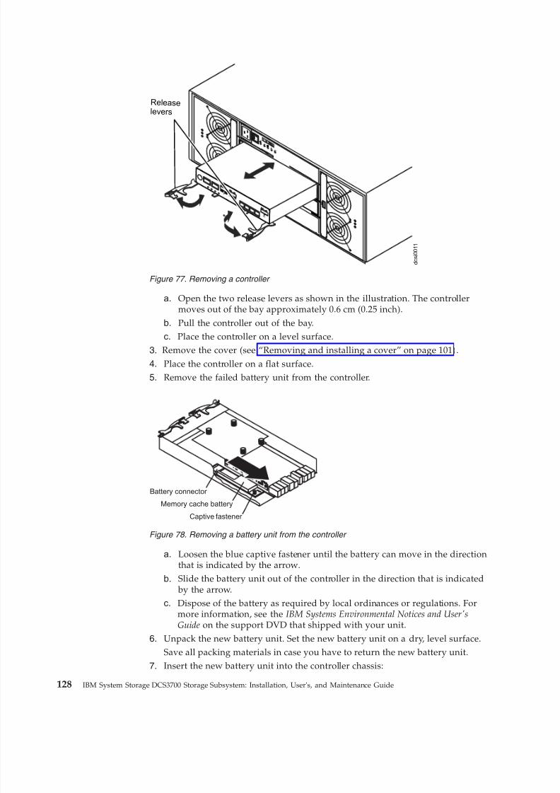
8/9/2019 Installation, User's, And Maintenance
http://slidepdf.com/reader/full/installation-users-and-maintenance 146/262
a. Open the two release levers as shown in the illustration. The controllermoves out of the bay approximately 0.6 cm (0.25 inch).
b. Pull the controller out of the bay.c. Place the controller on a level surface.
3. Remove the cover (see “Removing and installing a cover” on page 101).
4. Place the controller on a flat surface.5. Remove the failed battery unit from the controller.
a. Loosen the blue captive fastener until the battery can move in the directionthat is indicated by the arrow.
b. Slide the battery unit out of the controller in the direction that is indicated by the arrow.
c. Dispose of the battery as required by local ordinances or regulations. Formore information, see the IBM Systems Environmental Notices and User'sGuide on the support DVD that shipped with your unit.
6. Unpack the new battery unit. Set the new battery unit on a dry, level surface.Save all packing materials in case you have to return the new battery unit.
7. Insert the new battery unit into the controller chassis:
AC
DC
2
1
I
O
d c s i 0 0 1 1
Release
lever s
Figure 77. Removing a controller
Battery connector
Captive fastener
Memory cache battery
Figure 78. Removing a battery unit from the controller
128 IBM System Storage DCS3700 Storage Subsystem: Installation, User's, and Maintenance Guide
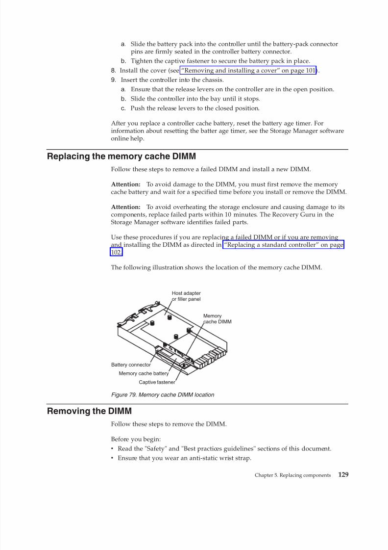
8/9/2019 Installation, User's, And Maintenance
http://slidepdf.com/reader/full/installation-users-and-maintenance 147/262
a. Slide the battery pack into the controller until the battery-pack connectorpins are firmly seated in the controller battery connector.
b. Tighten the captive fastener to secure the battery pack in place.
8. Install the cover (see “Removing and installing a cover” on page 101).9. Insert the controller into the chassis.
a. Ensure that the release levers on the controller are in the open position.
b. Slide the controller into the bay until it stops.c. Push the release levers to the closed position.
After you replace a controller cache battery, reset the battery age timer. Forinformation about resetting the batter age timer, see the Storage Manager softwareonline help.
Replacing the memory cache DIMM
Follow these steps to remove a failed DIMM and install a new DIMM.
Attention: To avoid damage to the DIMM, you must first remove the memory
cache battery and wait for a specified time before you install or remove the DIMM.
Attention: To avoid overheating the storage enclosure and causing damage to itscomponents, replace failed parts within 10 minutes. The Recovery Guru in theStorage Manager software identifies failed parts.
Use these procedures if you are replacing a failed DIMM or if you are removingand installing the DIMM as directed in “Replacing a standard controller” on page102.
The following illustration shows the location of the memory cache DIMM.
Removing the DIMM
Follow these steps to remove the DIMM.
Before you begin:v Read the "Safety" and "Best practices guidelines" sections of this document.v Ensure that you wear an anti-static wrist strap.
Battery connector
Captive fastener
Memory cache battery
Memorycache DIMM
Host adapter or filler panel
Figure 79. Memory cache DIMM location
Chapter 5. Replacing components 129
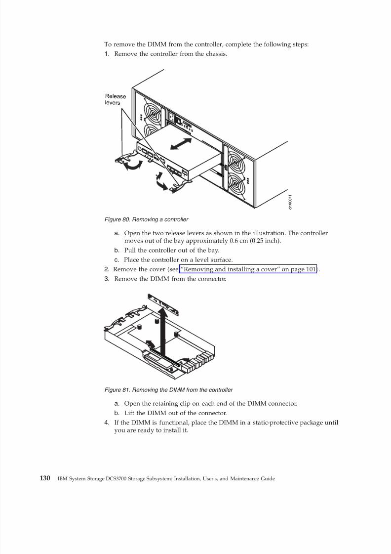
8/9/2019 Installation, User's, And Maintenance
http://slidepdf.com/reader/full/installation-users-and-maintenance 148/262
To remove the DIMM from the controller, complete the following steps:1. Remove the controller from the chassis.
a. Open the two release levers as shown in the illustration. The controllermoves out of the bay approximately 0.6 cm (0.25 inch).
b. Pull the controller out of the bay.c. Place the controller on a level surface.
2. Remove the cover (see “Removing and installing a cover” on page 101).
3. Remove the DIMM from the connector.
a. Open the retaining clip on each end of the DIMM connector.
b. Lift the DIMM out of the connector.4. If the DIMM is functional, place the DIMM in a static-protective package until
you are ready to install it.
AC
DC
2
1
I
O
d c s i 0 0 1 1
Releaselever s
Figure 80. Removing a controller
Figure 81. Removing the DIMM from the controller
130 IBM System Storage DCS3700 Storage Subsystem: Installation, User's, and Maintenance Guide

8/9/2019 Installation, User's, And Maintenance
http://slidepdf.com/reader/full/installation-users-and-maintenance 149/262
Installing the DIMM
Follow these steps to install a new DIMM.
Before you begin, ensure that you wear an anti-static wrist strap.
Complete the following steps to install the DIMM in the controller:
1. Open the retaining clip on each end of the DIMM connector.2. Touch the static-protective package that contains the DIMM to any unpainted
metal surface on the storage subsystem. Then, remove the DIMM from thepackage.
3. Turn the DIMM so that the DIMM keys align correctly with the slot.
4. Match the angle of the DIMM with the angle of the connector.5. Firmly press the DIMM into the connector. The retaining clips snap into the
locked position when the DIMM is firmly seated in the connector. If there is agap between the DIMM and the retaining clips, the DIMM has not been
correctly inserted. Open the retaining clips, remove the DIMM, and thenreinsert it.
6. Install the cover (see “Removing and installing a cover” on page 101).
7. Insert the controller into the chassis.
a. Ensure that the release levers on the controller are in the open position.b. Slide the controller into the bay until it stops.
c. Push the release levers to the closed position.
Attention: After you remove a controller, wait 90 seconds before you reseat orreplace the controller. Failure to do so might cause unpredictable results.
Removing and replacing the cache backup flash memory deviceFollow these steps to remove and replace the cache backup flash memory device.
Before you begin, ensure that you wear an anti-static wrist strap.
Complete the following steps to remove the cache backup flash memory devicefrom the controller.
Figure 82. Installing the DIMM in the controller
Chapter 5. Replacing components 131
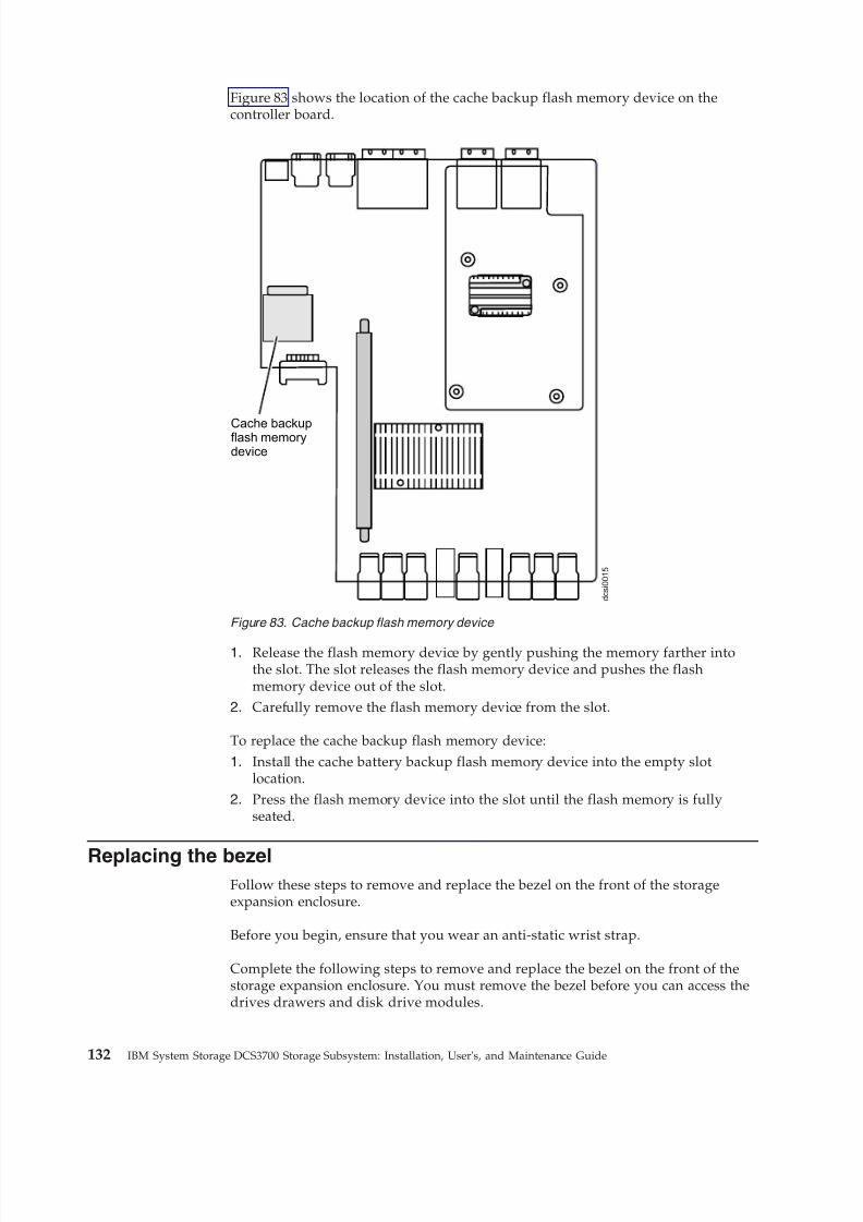
8/9/2019 Installation, User's, And Maintenance
http://slidepdf.com/reader/full/installation-users-and-maintenance 150/262
Figure 83 shows the location of the cache backup flash memory device on thecontroller board.
1. Release the flash memory device by gently pushing the memory farther intothe slot. The slot releases the flash memory device and pushes the flashmemory device out of the slot.
2. Carefully remove the flash memory device from the slot.
To replace the cache backup flash memory device:
1. Install the cache battery backup flash memory device into the empty slotlocation.
2. Press the flash memory device into the slot until the flash memory is fullyseated.
Replacing the bezelFollow these steps to remove and replace the bezel on the front of the storageexpansion enclosure.
Before you begin, ensure that you wear an anti-static wrist strap.
Complete the following steps to remove and replace the bezel on the front of thestorage expansion enclosure. You must remove the bezel before you can access thedrives drawers and disk drive modules.
d c s i 0 0 1 5
Cache backupflash memorydevice
Figure 83. Cache backup flash memory device
132 IBM System Storage DCS3700 Storage Subsystem: Installation, User's, and Maintenance Guide
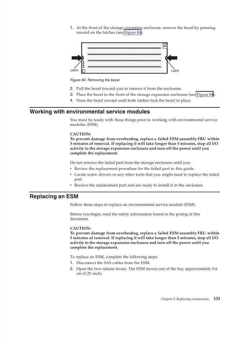
8/9/2019 Installation, User's, And Maintenance
http://slidepdf.com/reader/full/installation-users-and-maintenance 151/262
1. At the front of the storage expansion enclosure, remove the bezel by pressinginward on the latches (see Figure 84).
2. Pull the bezel toward you to remove it from the enclosure.
3. Place the bezel to the front of the storage expansion enclosure (see Figure 84).4. Press the bezel inward until both latches lock the bezel in place.
Working with environmental service modules
You must be ready with these things prior to working with environmental servicemodules (ESM).
CAUTION:To prevent damage from overheating, replace a failed ESM assembly FRU within5 minutes of removal. If replacing it will take longer than 5 minutes, stop all I/Oactivity to the storage expansion enclosure and turn off the power until youcomplete the replacement.
Do not remove the failed part from the storage enclosure until you:v Review the replacement procedure for the failed part in this guide.v Locate screw drivers or any other tools that you might need to replace the failed
part.v Receive the replacement part and are ready to install it in the enclosure.
Replacing an ESM
Follow these steps to replace an environmental service module (ESM).
Before you begin, read the safety information found in the prolog of thisdocument.
CAUTION:To prevent damage from overheating, replace a failed ESM assembly FRU within5 minutes of removal. If replacing it will take longer than 5 minutes, stop all I/O
activity to the storage expansion enclosure and turn off the power until youcomplete the replacement.
To replace an ESM, complete the following steps:
1. Disconnect the SAS cables from the ESM.2. Open the two release levers. The ESM moves out of the bay approximately 0.6
cm (0.25 inch).
Latch Latch
Figure 84. Removing the bezel
Chapter 5. Replacing components 133
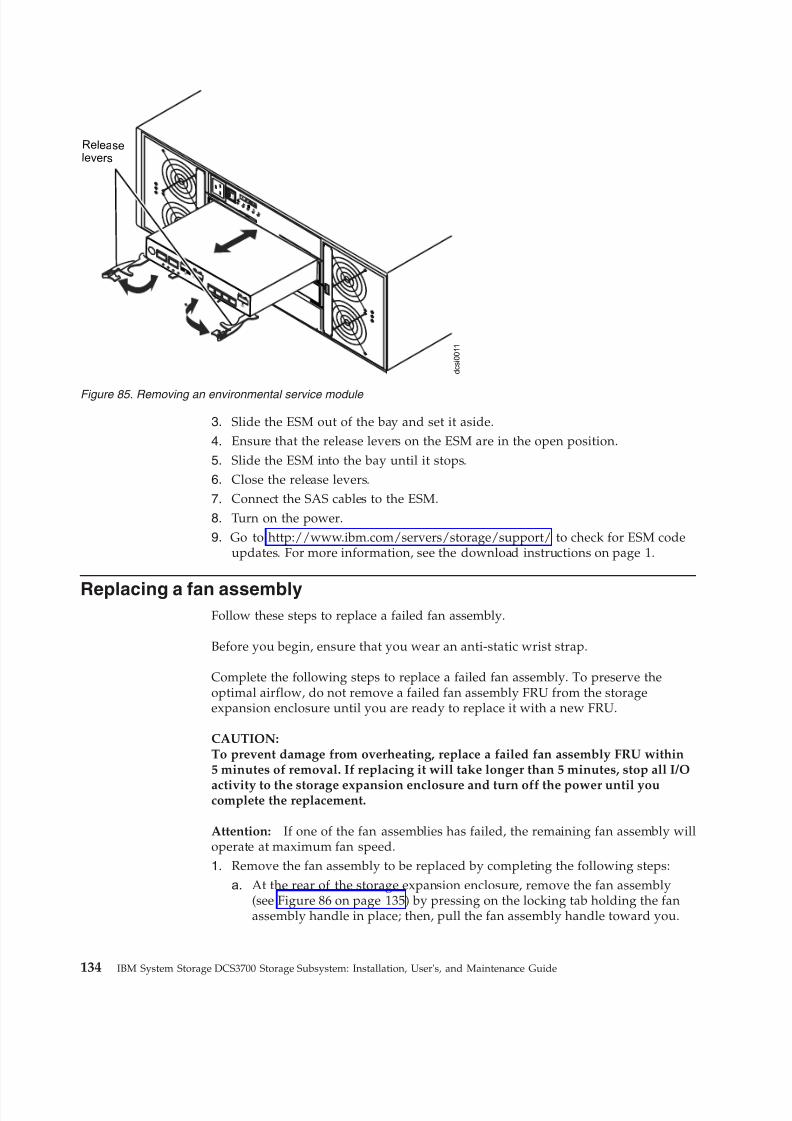
8/9/2019 Installation, User's, And Maintenance
http://slidepdf.com/reader/full/installation-users-and-maintenance 152/262
3. Slide the ESM out of the bay and set it aside.
4. Ensure that the release levers on the ESM are in the open position.
5. Slide the ESM into the bay until it stops.6. Close the release levers.
7. Connect the SAS cables to the ESM.
8. Turn on the power.9. Go to http://www.ibm.com/servers/storage/support/ to check for ESM code
updates. For more information, see the download instructions on page 1.
Replacing a fan assemblyFollow these steps to replace a failed fan assembly.
Before you begin, ensure that you wear an anti-static wrist strap.
Complete the following steps to replace a failed fan assembly. To preserve theoptimal airflow, do not remove a failed fan assembly FRU from the storageexpansion enclosure until you are ready to replace it with a new FRU.
CAUTION:To prevent damage from overheating, replace a failed fan assembly FRU within5 minutes of removal. If replacing it will take longer than 5 minutes, stop all I/O
activity to the storage expansion enclosure and turn off the power until youcomplete the replacement.
Attention: If one of the fan assemblies has failed, the remaining fan assembly willoperate at maximum fan speed.
1. Remove the fan assembly to be replaced by completing the following steps:
a. At the rear of the storage expansion enclosure, remove the fan assembly(see Figure 86 on page 135) by pressing on the locking tab holding the fanassembly handle in place; then, pull the fan assembly handle toward you.
AC
DC
2
1
I
O
d c s i 0 0 1 1
Release
lever s
Figure 85. Removing an environmental service module
134 IBM System Storage DCS3700 Storage Subsystem: Installation, User's, and Maintenance Guide
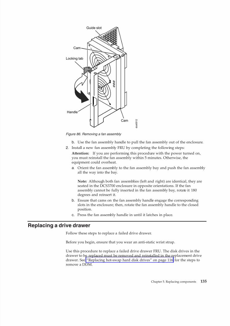
8/9/2019 Installation, User's, And Maintenance
http://slidepdf.com/reader/full/installation-users-and-maintenance 153/262
b. Use the fan assembly handle to pull the fan assembly out of the enclosure.2. Install a new fan assembly FRU by completing the following steps:
Attention: If you are performing this procedure with the power turned on,you must reinstall the fan assembly within 5 minutes. Otherwise, theequipment could overheat.a. Orient the fan assembly to the fan assembly bay and push the fan assembly
all the way into the bay.
Note: Although both fan assemblies (left and right) are identical, they areseated in the DCS3700 enclosure in opposite orientations. If the fanassembly cannot be fully inserted in the fan assembly bay, rotate it 180degrees and reinsert it.
b. Ensure that cams on the fan assembly handle engage the correspondingslots in the enclosure; then, rotate the fan assembly handle to the closedposition.
c. Press the fan assembly handle in until it latches in place.
Replacing a drive drawer
Follow these steps to replace a failed drive drawer.
Before you begin, ensure that you wear an anti-static wrist strap.
Use this procedure to replace a failed drive drawer FRU. The disk drives in thedrawer to be replaced must be removed and reinstalled in the replacement drivedrawer. See “Replacing hot-swap hard disk drives” on page 116 for the steps toremove a DDM.
Handle
Cam
Locking tab
Cam
Guide slot
d c s i 0 0 1 2
Figure 86. Removing a fan assembly
Chapter 5. Replacing components 135
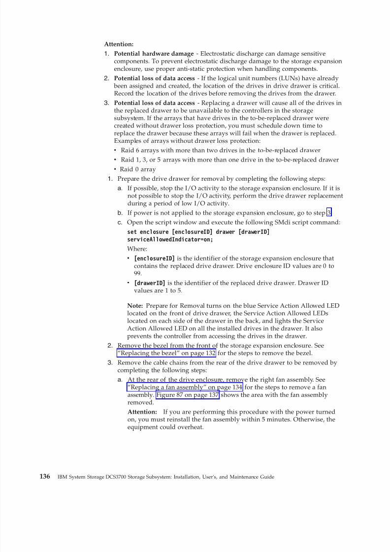
8/9/2019 Installation, User's, And Maintenance
http://slidepdf.com/reader/full/installation-users-and-maintenance 154/262
Attention:
1. Potential hardware damage - Electrostatic discharge can damage sensitivecomponents. To prevent electrostatic discharge damage to the storage expansionenclosure, use proper anti-static protection when handling components.
2. Potential loss of data access - If the logical unit numbers (LUNs) have already been assigned and created, the location of the drives in drive drawer is critical.
Record the location of the drives before removing the drives from the drawer.3. Potential loss of data access - Replacing a drawer will cause all of the drives inthe replaced drawer to be unavailable to the controllers in the storagesubsystem. If the arrays that have drives in the to-be-replaced drawer werecreated without drawer loss protection, you must schedule down time toreplace the drawer because these arrays will fail when the drawer is replaced.Examples of arrays without drawer loss protection:v Raid 6 arrays with more than two drives in the to-be-replaced drawerv Raid 1, 3, or 5 arrays with more than one drive in the to-be-replaced drawerv Raid 0 array
1. Prepare the drive drawer for removal by completing the following steps:a. If possible, stop the I/O activity to the storage expansion enclosure. If it is
not possible to stop the I/O activity, perform the drive drawer replacementduring a period of low I/O activity.
b. If power is not applied to the storage expansion enclosure, go to step 3.
c. Open the script window and execute the following SMcli script command:set enclosure [enclosureID] drawer [drawerID]
serviceAllowedIndicator=on;
Where:v [enclosureID] is the identifier of the storage expansion enclosure that
contains the replaced drive drawer. Drive enclosure ID values are 0 to99.
v [drawerID] is the identifier of the replaced drive drawer. Drawer ID
values are 1 to 5.
Note: Prepare for Removal turns on the blue Service Action Allowed LEDlocated on the front of drive drawer, the Service Action Allowed LEDslocated on each side of the drawer in the back, and lights the ServiceAction Allowed LED on all the installed drives in the drawer. It alsoprevents the controller from accessing the drives in the drawer.
2. Remove the bezel from the front of the storage expansion enclosure. See“Replacing the bezel” on page 132 for the steps to remove the bezel.
3. Remove the cable chains from the rear of the drive drawer to be removed bycompleting the following steps:a. At the rear of the drive enclosure, remove the right fan assembly. See
“Replacing a fan assembly” on page 134 for the steps to remove a fanassembly. Figure 87 on page 137 shows the area with the fan assemblyremoved.Attention: If you are performing this procedure with the power turnedon, you must reinstall the fan assembly within 5 minutes. Otherwise, theequipment could overheat.
136 IBM System Storage DCS3700 Storage Subsystem: Installation, User's, and Maintenance Guide
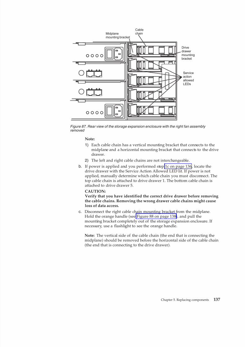
8/9/2019 Installation, User's, And Maintenance
http://slidepdf.com/reader/full/installation-users-and-maintenance 155/262
Note:
1) Each cable chain has a vertical mounting bracket that connects to themidplane and a horizontal mounting bracket that connects to the drivedrawer.
2) The left and right cable chains are not interchangeable.b. If power is applied and you performed step 1c on page 136, locate the
drive drawer with the Service Action Allowed LED lit. If power is notapplied, manually determine which cable chain you must disconnect. The
top cable chain is attached to drive drawer 1. The bottom cable chain isattached to drive drawer 5.CAUTION:Verify that you have identified the correct drive drawer before removingthe cable chains. Removing the wrong drawer cable chains might causeloss of data access.
c. Disconnect the right cable chain mounting bracket from the midplane.Hold the orange handle (see Figure 88 on page 138), and pull themounting bracket completely out of the storage expansion enclosure. If necessary, use a flashlight to see the orange handle.
Note: The vertical side of the cable chain (the end that is connecting themidplane) should be removed before the horizontal side of the cable chain(the end that is connecting to the drive drawer).
Midplanemounting bracket
Cablechain
Drivedrawer mountingbracket
ServiceactionallowedLEDs
Figure 87. Rear view of the storage expansion enclosure with the right fan assembly removed
Chapter 5. Replacing components 137

8/9/2019 Installation, User's, And Maintenance
http://slidepdf.com/reader/full/installation-users-and-maintenance 156/262
d. Disconnect the right cable chain mounting bracket from the drive drawer.Hold the orange handle (see Figure 89), and pull the mounting bracketcompletely out of the drive enclosure. Remove the right cable chain.
e. Reinstall the right fan assembly. Wait until the fan speed slows down andthe green Power LED is lit before proceeding to ensure that the right fanassembly is operating correctly before removing the left fan assembly. See“Replacing a fan assembly” on page 134 for the steps to install a fanassembly.
f. Remove the left fan assembly. See “Replacing a fan assembly” on page 134for the steps to remove a fan assembly.Attention: If you are performing this procedure with the power turnedon, you must reinstall the fan assembly within 10 minutes. Otherwise, theequipment could overheat.
g. Disconnect the left cable chain mounting bracket from the midplane. Holdthe orange handle and pull the mounting bracket completely out of thestorage expansion enclosure.
Orange circle
Figure 88. Vertical mounting bracket that connects to the midplane
Orange circle
Figure 89. Horizontal mounting bracket that connects to the drive drawer
138 IBM System Storage DCS3700 Storage Subsystem: Installation, User's, and Maintenance Guide
8/9/2019 Installation, User's, And Maintenance
http://slidepdf.com/reader/full/installation-users-and-maintenance 157/262
h. Disconnect the left cable chain mounting bracket from the drive drawer.Hold the orange handle and pull the mounting bracket completely out of the storage expansion enclosure. Remove the left cable chain.
i. Reinstall the left fan assembly. See “Replacing a fan assembly” on page 134for the steps to install a fan assembly.Attention: If you are performing this procedure with the power turned
on, you must reinstall the fan assemblies before you remove the drivedrawer. Otherwise, the equipment could overheat.4. Remove the drive drawer by completing the following steps:
a. At the front of the storage expansion enclosure, pull the handles on thedrive drawer to be removed until the drive drawer stops. The drivedrawer should not come completely out of the enclosure at this time.
b. Label all of the disk drives in the drawer before you remove them, so thatthe drives can be reinstalled in the same slot in the replacement drivedrawer.Attention: If the logical unit numbers (LUNs) have already been assignedand created, the location of the drives in drive drawer is critical. You mustrecord the location of the drives before removing them in the next step.
c. Remove all of the disk drive modules from the drive drawer. See“Replacing hot-swap hard disk drives” on page 116 for the steps to removea DDM.
d. Slide the drive drawer release lever (see Figure 90) on both sides of thedrive drawer toward you, and remove the drive drawer from theenclosure.
5. Install a new drive drawer FRU by completing the following steps:Attention: Damage might occur if the lock-out tumbler is in the middle of the drawer guide.a. At the front of the storage expansion enclosure, install the new drive
drawer into the slot, making sure the lock-out tumbler is located on thetop of the drawer guide. The lock-out tumbler is a small alignment piecethat is attached to the frame. Figure 91 on page 140 shows the location of the lock-out tumbler as shown from the front of the enclosure.
Rear Front
Drive drawer release lever
Figure 90. Drive drawer release lever on the side of the drive drawer
Chapter 5. Replacing components 139
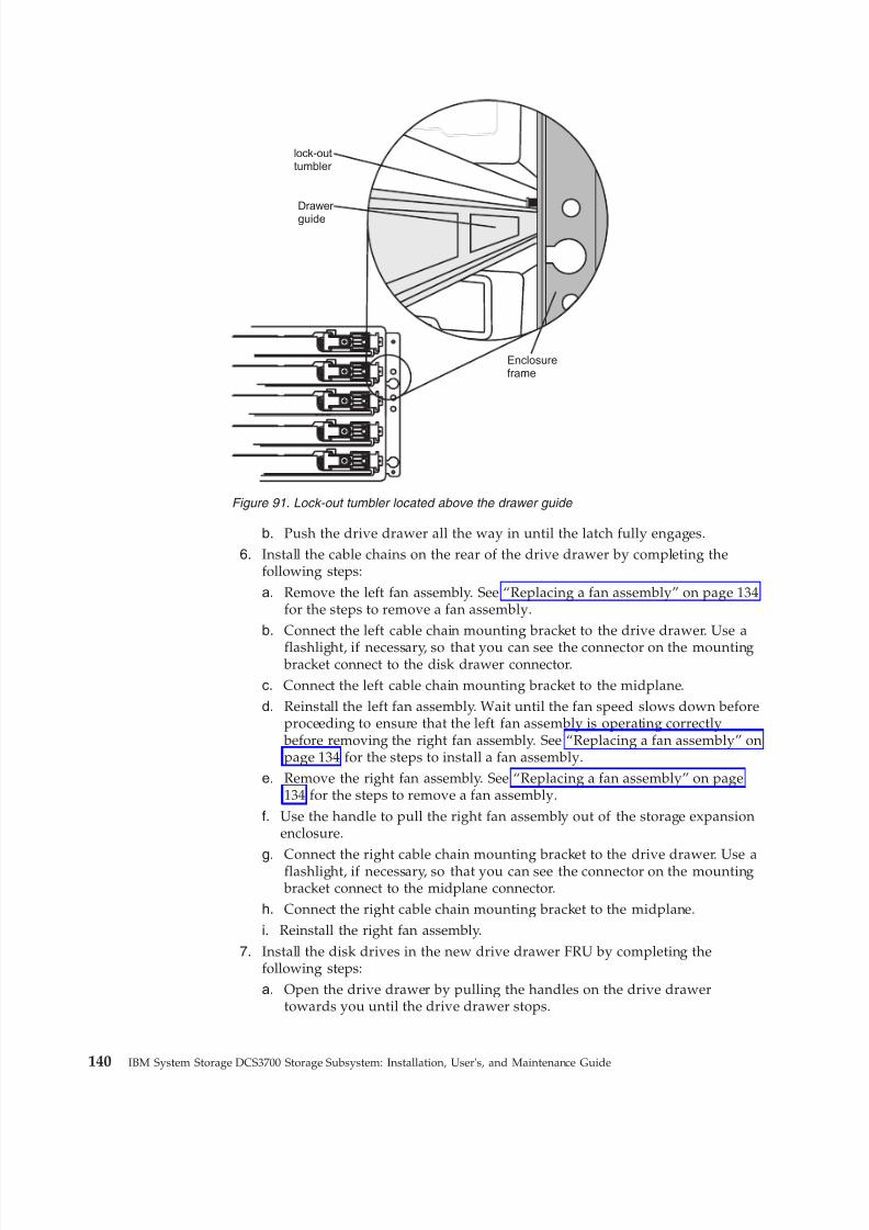
8/9/2019 Installation, User's, And Maintenance
http://slidepdf.com/reader/full/installation-users-and-maintenance 158/262
b. Push the drive drawer all the way in until the latch fully engages.6. Install the cable chains on the rear of the drive drawer by completing the
following steps:
a. Remove the left fan assembly. See “Replacing a fan assembly” on page 134for the steps to remove a fan assembly.
b. Connect the left cable chain mounting bracket to the drive drawer. Use a
flashlight, if necessary, so that you can see the connector on the mounting bracket connect to the disk drawer connector.
c. Connect the left cable chain mounting bracket to the midplane.d. Reinstall the left fan assembly. Wait until the fan speed slows down before
proceeding to ensure that the left fan assembly is operating correctly before removing the right fan assembly. See “Replacing a fan assembly” onpage 134 for the steps to install a fan assembly.
e. Remove the right fan assembly. See “Replacing a fan assembly” on page134 for the steps to remove a fan assembly.
f. Use the handle to pull the right fan assembly out of the storage expansionenclosure.
g. Connect the right cable chain mounting bracket to the drive drawer. Use aflashlight, if necessary, so that you can see the connector on the mounting bracket connect to the midplane connector.
h. Connect the right cable chain mounting bracket to the midplane.
i. Reinstall the right fan assembly.
7. Install the disk drives in the new drive drawer FRU by completing thefollowing steps:a. Open the drive drawer by pulling the handles on the drive drawer
towards you until the drive drawer stops.
Drawer
guide
lock-outtumbler
Enclosureframe
Figure 91. Lock-out tumbler located above the drawer guide
140 IBM System Storage DCS3700 Storage Subsystem: Installation, User's, and Maintenance Guide

8/9/2019 Installation, User's, And Maintenance
http://slidepdf.com/reader/full/installation-users-and-maintenance 159/262
b. Install the drives you that you removed previously in the drive drawer,one disk drive at a time. Wait at least 90 seconds or until each drive isrecognized in the DS Storage Manager Physical View before inserting thenext drive. If you do not wait until the drive is recognized by the DSStorage Manager, one or more drives will be marked as failed/bypassed orincompatible. If this occurs, you must remove the failed/bypassed drive,reinsert it, and wait at least 90 seconds or until it is recognized by the DS
Storage Manager. See “Installing hot-swap hard disk drives” on page 116for the steps to install the drives.Attention: You must add the drives to the same location in the drivedrawer that they were in before the drive drawer was replaced.
c. Push the drive drawer all the way in until the latch fully engages.
8. Install the bezel on the front of the storage expansion enclosure. See“Replacing the bezel” on page 132 for the steps to install the bezel.
9. Remove the anti-static protection.
10. Is the storage expansion enclosure power turned on?v No - You are finished with the procedure, and you can turn on the power.v Yes - Go to step 11
11. The Service Action Allowed LED on the replaced drive drawer should beturned off automatically by the controllers. If it is not turned off automatically,open the script window for the DCS3700 storage subsystem, and execute thefollowing SMcli script command:set enclosure [enclosureID] drawer [drawerID]
serviceAllowedIndicator=off;
Where:v [enclosureID] is the identifier of the storage expansion enclosure that
contains the replaced drive drawer. Drive enclosure ID values are 0 to 99.v [drawerID] is the identifier of the replaced drive drawer. Drawer ID values
are 1 to 5.
This command turns off the blue Service Action Allowed LED that is locatedon the drive drawer and allows the controller to access the storage expansionenclosure.
12. Use the DS Storage Manager to verify that the new drive drawer is operatingcorrectly.
Replacing an enclosure chassis
Follow these steps to replace an enclosure chassis.
The replacement chassis package includes a RID tag and a power supply module.You can either ship this power supply module or your existing power supply
module back to IBM along with the old enclosure chassis.Before you begin, ensure that you wear an anti-static wrist strap.
Complete the following steps to replace the enclosure chassis.1. Schedule downtime for the storage subsystem configuration, and:
a. Stop all applications in the servers, and either unmount or remove thedrive letters of the mapped LUNs from the storage subsystem.
Chapter 5. Replacing components 141
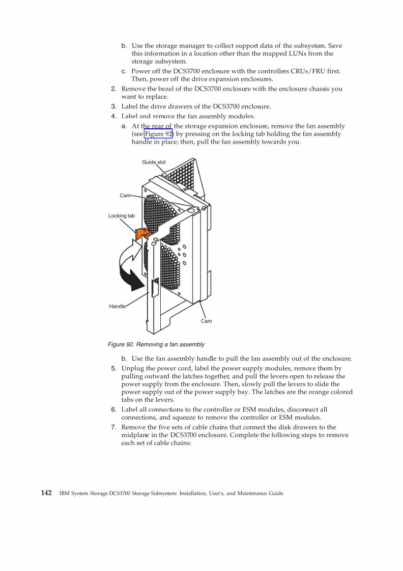
8/9/2019 Installation, User's, And Maintenance
http://slidepdf.com/reader/full/installation-users-and-maintenance 160/262
b. Use the storage manager to collect support data of the subsystem. Savethis information in a location other than the mapped LUNs from thestorage subsystem.
c. Power off the DCS3700 enclosure with the controllers CRUs/FRU first.Then, power off the drive expansion enclosures.
2. Remove the bezel of the DCS3700 enclosure with the enclosure chassis you
want to replace.3. Label the drive drawers of the DCS3700 enclosure.4. Label and remove the fan assembly modules.
a. At the rear of the storage expansion enclosure, remove the fan assembly(see Figure 92) by pressing on the locking tab holding the fan assemblyhandle in place; then, pull the fan assembly towards you.
b. Use the fan assembly handle to pull the fan assembly out of the enclosure.
5. Unplug the power cord, label the power supply modules, remove them bypulling outward the latches together, and pull the levers open to release thepower supply from the enclosure. Then, slowly pull the levers to slide thepower supply out of the power supply bay. The latches are the orange colored
tabs on the levers.6. Label all connections to the controller or ESM modules, disconnect all
connections, and squeeze to remove the controller or ESM modules.7. Remove the five sets of cable chains that connect the disk drawers to the
midplane in the DCS3700 enclosure. Complete the following steps to removeeach set of cable chains:
Handle
Cam
Locking tab
Cam
Guide slot
Figure 92. Removing a fan assembly
142 IBM System Storage DCS3700 Storage Subsystem: Installation, User's, and Maintenance Guide
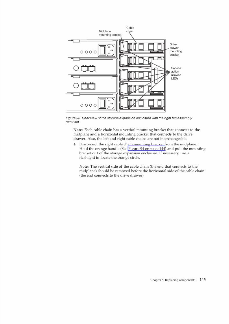
8/9/2019 Installation, User's, And Maintenance
http://slidepdf.com/reader/full/installation-users-and-maintenance 161/262
Note: Each cable chain has a vertical mounting bracket that connects to themidplane and a horizontal mounting bracket that connects to the drivedrawer. Also, the left and right cable chains are not interchangeable.
a. Disconnect the right cable chain mounting bracket from the midplane.Hold the orange handle (See Figure 94 on page 144) and pull the mounting
bracket out of the storage expansion enclosure. If necessary, use aflashlight to locate the orange circle.
Note: The vertical side of the cable chain (the end that connects to the
midplane) should be removed before the horizontal side of the cable chain(the end connects to the drive drawer).
Midplanemounting bracket
Cablechain
Drivedrawer mountingbracket
ServiceactionallowedLEDs
Figure 93. Rear view of the storage expansion enclosure with the right fan assembly removed
Chapter 5. Replacing components 143
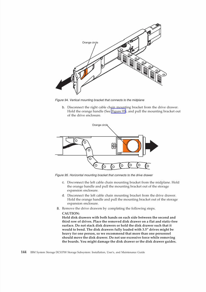
8/9/2019 Installation, User's, And Maintenance
http://slidepdf.com/reader/full/installation-users-and-maintenance 162/262
b. Disconnect the right cable chain mounting bracket from the drive drawer.Hold the orange handle (See Figure 95), and pull the mounting bracket outof the drive enclosure.
c. Disconnect the left cable chain mounting bracket from the midplane. Holdthe orange handle and pull the mounting bracket out of the storageexpansion enclosure.
d. Disconnect the left cable chain mounting bracket from the drive drawer.Hold the orange handle and pull the mounting bracket out of the storage
expansion enclosure.8. Remove the drive drawers by completing the following steps.CAUTION:Hold disk drawers with both hands on each side between the second andthird row of drives. Place the removed disk drawer on a flat and static-freesurface. Do not stack disk drawers or hold the disk drawer such that itwould to bend. The disk drawers fully loaded with 3.5” drives might beheavy for one person, so we recommend that more than one personnelshould move the disk drawer. Do not use excessive force while removingthe boards. You might damage the disk drawer or the disk drawer guides.
Orange circle
Figure 94. Vertical mounting bracket that connects to the midplane
Orange circle
Figure 95. Horizontal mounting bracket that connects to the drive drawer
144 IBM System Storage DCS3700 Storage Subsystem: Installation, User's, and Maintenance Guide
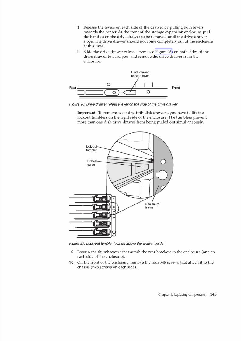
8/9/2019 Installation, User's, And Maintenance
http://slidepdf.com/reader/full/installation-users-and-maintenance 163/262
a. Release the levers on each side of the drawer by pulling both leverstowards the center. At the front of the storage expansion enclosure, pullthe handles on the drive drawer to be removed until the drive drawerstops. The drive drawer should not come completely out of the enclosureat this time.
b. Slide the drive drawer release lever (see Figure 96) on both sides of thedrive drawer toward you, and remove the drive drawer from theenclosure.
Important: To remove second to fifth disk drawers, you have to lift the
lockout tumblers on the right side of the enclosure. The tumblers preventmore than one disk drive drawer from being pulled out simultaneously.
9. Loosen the thumbscrews that attach the rear brackets to the enclosure (one oneach side of the enclosure).
10. On the front of the enclosure, remove the four M5 screws that attach it to thechassis (two screws on each side).
Rear Front
Drive drawer release lever
Figure 96. Drive drawer release lever on the side of the drive drawer
Drawer guide
lock-outtumbler
Enclosureframe
Figure 97. Lock-out tumbler located above the drawer guide
Chapter 5. Replacing components 145
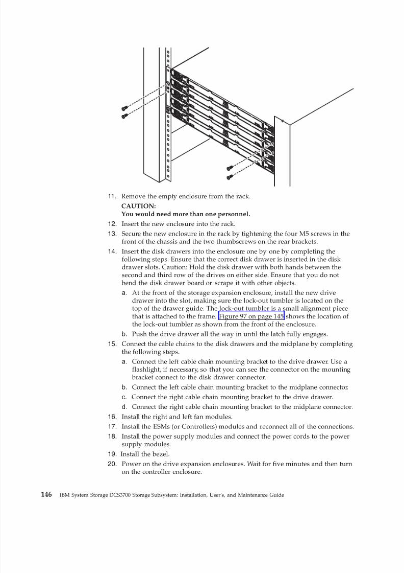
8/9/2019 Installation, User's, And Maintenance
http://slidepdf.com/reader/full/installation-users-and-maintenance 164/262
11. Remove the empty enclosure from the rack.CAUTION:You would need more than one personnel.
12. Insert the new enclosure into the rack.13. Secure the new enclosure in the rack by tightening the four M5 screws in the
front of the chassis and the two thumbscrews on the rear brackets.
14. Insert the disk drawers into the enclosure one by one by completing thefollowing steps. Ensure that the correct disk drawer is inserted in the diskdrawer slots. Caution: Hold the disk drawer with both hands between thesecond and third row of the drives on either side. Ensure that you do not
bend the disk drawer board or scrape it with other objects.a. At the front of the storage expansion enclosure, install the new drive
drawer into the slot, making sure the lock-out tumbler is located on thetop of the drawer guide. The lock-out tumbler is a small alignment piecethat is attached to the frame. Figure 97 on page 145 shows the location of the lock-out tumbler as shown from the front of the enclosure.
b. Push the drive drawer all the way in until the latch fully engages.
15. Connect the cable chains to the disk drawers and the midplane by completingthe following steps.a. Connect the left cable chain mounting bracket to the drive drawer. Use a
flashlight, if necessary, so that you can see the connector on the mounting bracket connect to the disk drawer connector.
b. Connect the left cable chain mounting bracket to the midplane connector.c. Connect the right cable chain mounting bracket to the drive drawer.
d. Connect the right cable chain mounting bracket to the midplane connector.
16. Install the right and left fan modules.17. Install the ESMs (or Controllers) modules and reconnect all of the connections.18. Install the power supply modules and connect the power cords to the power
supply modules.
19. Install the bezel.20. Power on the drive expansion enclosures. Wait for five minutes and then turn
on the controller enclosure.
146 IBM System Storage DCS3700 Storage Subsystem: Installation, User's, and Maintenance Guide
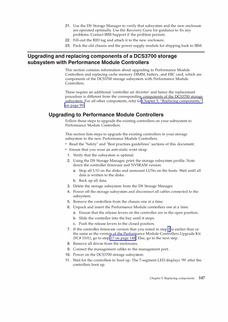
8/9/2019 Installation, User's, And Maintenance
http://slidepdf.com/reader/full/installation-users-and-maintenance 165/262
21. Use the DS Storage Manager to verify that subsystem and the new enclosureare operated optimally. Use the Recovery Guru for guidance to fix anyproblems. Contact IBM Support if the problem persists.
22. Fill-out the RID tag and attach it to the new enclosure.23. Pack the old chassis and the power supply module for shipping back to IBM.
Upgrading and replacing components of a DCS3700 storagesubsystem with Performance Module Controllers
This section contains information about upgrading to Performance ModuleControllers and replacing cache memory DIMM, battery, and HIC card, which arecomponents of the DCS3700 storage subsystem with Performance ModuleControllers.
These require an additional 'controller air diverter' and hence the replacementprocedure is different from the corresponding components of the DCS3700 storagesubsystem. For all other components, refer to Chapter 5, “Replacing components,”on page 99.
Upgrading to Performance Module ControllersFollow these steps to upgrade the existing controllers on your subsystem toPerformance Module Controllers.
This section lists steps to upgrade the existing controllers in your storagesubsystem to the new Performance Module Controllers.v Read the "Safety" and "Best practices guidelines" sections of this document.v Ensure that you wear an anti-static wrist strap.
1. Verify that the subsystem is optimal.2. Using the DS Storage Manager, print the storage subsystem profile. Note
down the controller firmware and NVSRAM version.
a. Stop all I/O on the disks and unmount LUNs on the hosts. Wait until alldata is written to the disks.
b. Back up all data.
3. Delete the storage subsystem from the DS Storage Manager.
4. Power off the storage subsystem and disconnect all cables connected to thesubsystem.
5. Remove the controllers from the chassis one at a time.
6. Unpack and insert the Performance Module controllers one at a time.
a. Ensure that the release levers on the controller are in the open position.b. Slide the controller into the bay until it stops.
c. Push the release levers to the closed position.7. If the controller firmware version that you noted in step 2 is earlier than or
the same as the version of the Performance Module Controllers Upgrade Kit(FC# 3101), go to step 17 on page 148. Else, go to the next step.
8. Remove all drives from the enclosures.
9. Connect the management cables to the management port.10. Power on the DCS3700 storage subsystem.11. Wait for the controllers to boot up. The 7-segment LED displays '99' after the
controllers boot up.
Chapter 5. Replacing components 147
8/9/2019 Installation, User's, And Maintenance
http://slidepdf.com/reader/full/installation-users-and-maintenance 166/262
12. Depending on the fabric design, add the storage subsystem to the DS StorageManager using the IP address. The ethernet ports have the following defaultIP addresses:v Ports 1 and 2 on controller A - 192.168.128.101 and 192.168.129.101v Ports 1 and 2 on controller B - 192.168.128.102 and 192.168.129.102
If you are using DHCP, check the DHCP server for the allocated IP addresses.
13. Download the controller firmware and NVSRAM, as noted down in step 2 onpage 147, to the Performance Module Controllers. The 7-segment LEDdisplays '99' after download is complete.
14. Power off the DCS3700 storage subsystem.
15. Remove the DCS3700 storage subsystem from the DS Storage Manager.16. Insert the drives in the same slots that they were in earlier.17. Reconnect the cables that you disconnected in step 4 on page 147.
18. Power on the DCS3700 storage subsystem. Wait for the subsystem tosynchronize with the existing configuration.
19. Check the 7-segment LED on the newly inserted controllers. The LED displays'99' after boot up.
20. Add the storage subsystem to the DS Storage Manager using DHCP or the IPaddress.
21. Using the Subsystem management window, verify that all components of thestorage subsystem are optimal.
Replacing a Performance Module ControllerFollow these steps to replace a failed controller on a subsystem with PerformanceModule Controllers.
This section lists steps to replace a failed controller in the DCS3700 storagesubsystem with Performance Module Controllers. Before you replace a controller:v
Ensure that both power supplies are connected and powered-on and no amberLEDs are lit. Ensure that the power LEDs on both power supplies are lit. If thestatus of either of the power supplies is not Optimal, replace that power supply
before you proceed with the controller replacement procedure.v If you are replacing a failed controller with a replacement controller from IBM
Service, ensure that the replacement controller's cache memory is the same as inthe failed controller. Also, transfer the cache backup battery to the replacementcontroller. Transfer the battery exactly as described in this procedure. If you donot remove and insert in the correct sequence, you could damage the controller.
v Read the "Safety" and "Best practices guidelines" sections of this document.v Check the WWIDs or the MAC addresses of the host ports after replacing the
controller and/or the host port interface adapter. If you need to change any
WWID or MAC address, update the servers or switches in the configuration.v Ensure that you wear an anti-static wrist strap.
Note: You require an additional controller air diverter while replacing thecontroller in a DCS3700 storage subsystem with Performance Module Controllers.This is the only difference between replacing the controller in a DCS3700 storagesubsystem and replacing the same in a DCS3700 storage subsystem withPerformance Module Controllers.
To replace a controller in a DCS3700 storage system with Performance ModuleControllers:
148 IBM System Storage DCS3700 Storage Subsystem: Installation, User's, and Maintenance Guide

8/9/2019 Installation, User's, And Maintenance
http://slidepdf.com/reader/full/installation-users-and-maintenance 167/262
CAUTION:To avoid overheating the storage enclosure and causing damage to itscomponents, replace failed parts within 10 minutes unless directed otherwise.The Recovery Guru in the Storage Manager software identifies failed parts.
1. Use the Storage Manager software to print a storage subsystem profile.2. Move logical drive ownership to the other controller. If the controller that you
are replacing has failed but is still operating, move the failed controller to theOffline state.Attention: Never remove a controller unless the OK to remove LED is lit.Doing so can result in a loss of data.
3. Locate the failed controller by checking the amber LEDs on the controllers inthe storage system.
4. If the OK to remove LED is not lit, another component might require attention before you remove the controller. Use the Recovery Guru in the SubsystemManagement window to identify and correct any additional failures. If thereare none, proceed with step 5 to replace the controller.Attention: Static electricity can damage the storage subsystem and otherelectronic devices. To avoid damage, keep static-sensitive devices in their
static-protective packages until you are ready to install them.5. Unpack the new controller. Save all packing materials in case you have to
return the new controller.6. Determine whether the replacement controller will be controller A or
controller B (controller A is installed in slot SBB A; controller B is installed inslot SBB B), and then paste the controller labels for host ports and driveexpansion ports to the replacement controller. The controller labels andinstructions are included with the replacement controller. Ensure that thelabels are aligned correctly and do not cover any connectors or LEDs.Attention: Handle and install cables correctly to avoid degradedperformance or loss of communication with devices. See Chapter 3 "Cablingthe DCS3700" for more information.
7. Disconnect all attached interface cables from the failed controller. Be sure tolabel each cable so that you can reconnect it correctly to the new controller.
8. Remove the controller from the chassis
Chapter 5. Replacing components 149
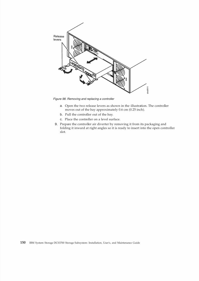
8/9/2019 Installation, User's, And Maintenance
http://slidepdf.com/reader/full/installation-users-and-maintenance 168/262
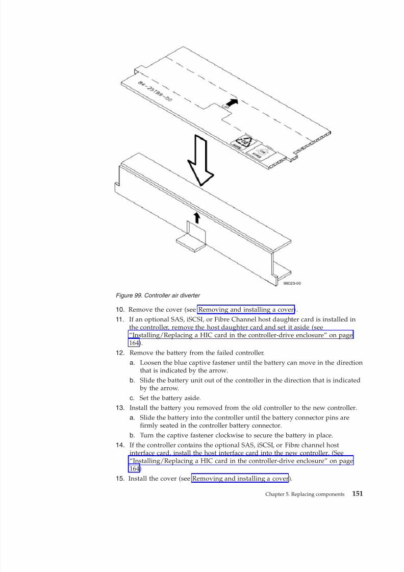
8/9/2019 Installation, User's, And Maintenance
http://slidepdf.com/reader/full/installation-users-and-maintenance 169/262
10. Remove the cover (see Removing and installing a cover).
11. If an optional SAS, iSCSI, or Fibre Channel host daughter card is installed inthe controller, remove the host daughter card and set it aside (see“Installing/Replacing a HIC card in the controller-drive enclosure” on page164).
12. Remove the battery from the failed controller.
a. Loosen the blue captive fastener until the battery can move in the directionthat is indicated by the arrow.
b. Slide the battery unit out of the controller in the direction that is indicated by the arrow.
c. Set the battery aside.13. Install the battery you removed from the old controller to the new controller.a. Slide the battery into the controller until the battery connector pins are
firmly seated in the controller battery connector.
b. Turn the captive fastener clockwise to secure the battery in place.14. If the controller contains the optional SAS, iSCSI, or Fibre channel host
interface card, install the host interface card into the new controller. (See“Installing/Replacing a HIC card in the controller-drive enclosure” on page164)
15. Install the cover (see Removing and installing a cover).
Figure 99. Controller air diverter
Chapter 5. Replacing components 151
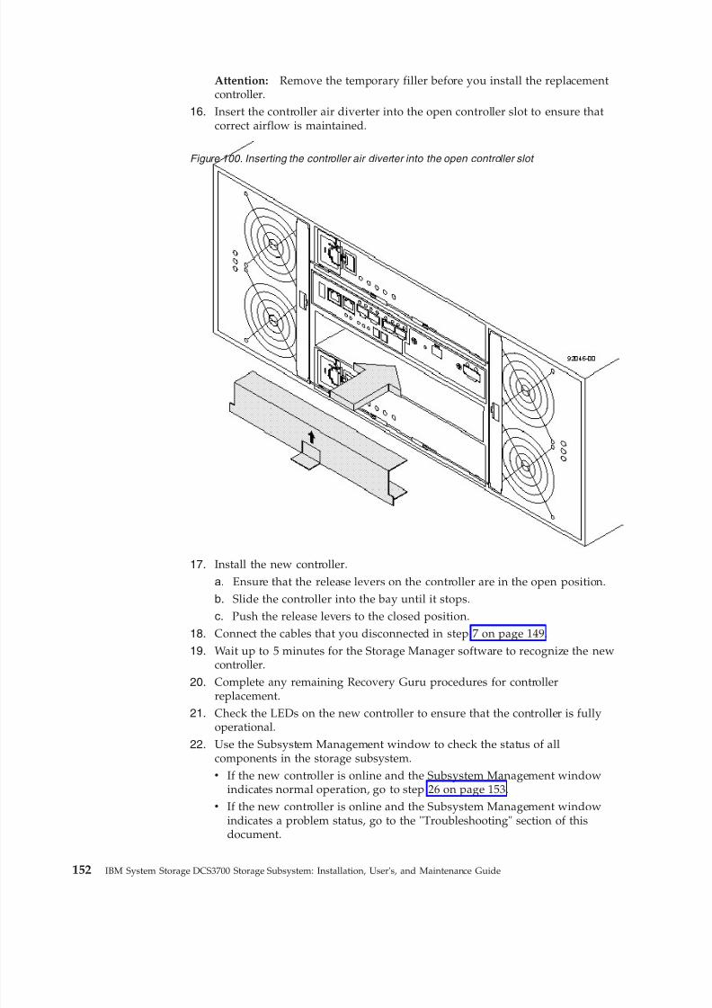
8/9/2019 Installation, User's, And Maintenance
http://slidepdf.com/reader/full/installation-users-and-maintenance 170/262
Attention: Remove the temporary filler before you install the replacementcontroller.
16. Insert the controller air diverter into the open controller slot to ensure thatcorrect airflow is maintained.
17. Install the new controller.
a. Ensure that the release levers on the controller are in the open position.b. Slide the controller into the bay until it stops.c. Push the release levers to the closed position.
18. Connect the cables that you disconnected in step 7 on page 149.
19. Wait up to 5 minutes for the Storage Manager software to recognize the newcontroller.
20. Complete any remaining Recovery Guru procedures for controllerreplacement.
21. Check the LEDs on the new controller to ensure that the controller is fullyoperational.
22. Use the Subsystem Management window to check the status of allcomponents in the storage subsystem.v If the new controller is online and the Subsystem Management window
indicates normal operation, go to step 26 on page 153.v If the new controller is online and the Subsystem Management window
indicates a problem status, go to the "Troubleshooting" section of thisdocument.
Figure 100. Inserting the controller air diverter into the open controller slot
152 IBM System Storage DCS3700 Storage Subsystem: Installation, User's, and Maintenance Guide
8/9/2019 Installation, User's, And Maintenance
http://slidepdf.com/reader/full/installation-users-and-maintenance 171/262
v If the new controller is offline, continue with step 23.23. If the newly inserted controller is in an offline state, see the Storage Manager
online help for instructions on bringing the controller online. If necessary,open the Subsystem Management window and place the controller online;select the offline controller and click Advanced → Recovery → Place controlleronline.
24. Check the state of the LEDs on the newly inserted controller. For moreinformation, see the "Controller LEDs" section of this document. You can alsouse the Subsystem Management window to identify any new faults.
25. If any storage subsystems has a fault (Needs Attention) status, click RecoveryGuru in the Subsystem Management window toolbar, and complete therecovery procedure. If the problem remains, contact your IBMtechnical-support representative.
26. If the storage subsystems have no fault, use the Storage Manager software toprint a new storage subsystem profile.
27. Check the WWIDs or the MAC addresses of the host ports after replacing thecontroller and/or the host port interface adapter. If you need to change anyWWID or MAC address, update the servers or switches in the configuration.
Note: You might have to reboot your system to remove the LUNs informationthat is associated with the WWID of the controller that you removed.
Replacing a Cache Memory DIMMFollow these steps to replace a Cache Memory DIMM on a subsystem withPerformance Module Controllers.1. Wear anti-static protection.
2. Remove the controller.
a. Unlock and pull out the release levers to release the controller.b. Using the release levers and your hands, pull the controller out of the
controller-drive enclosure.
3. Set the controller on a flat, static-free surface with release levers up.4. Prepare the controller air diverter by removing it from its packaging and
folding it inward at right angles so it is ready to insert into the open controllerslot.
Chapter 5. Replacing components 153
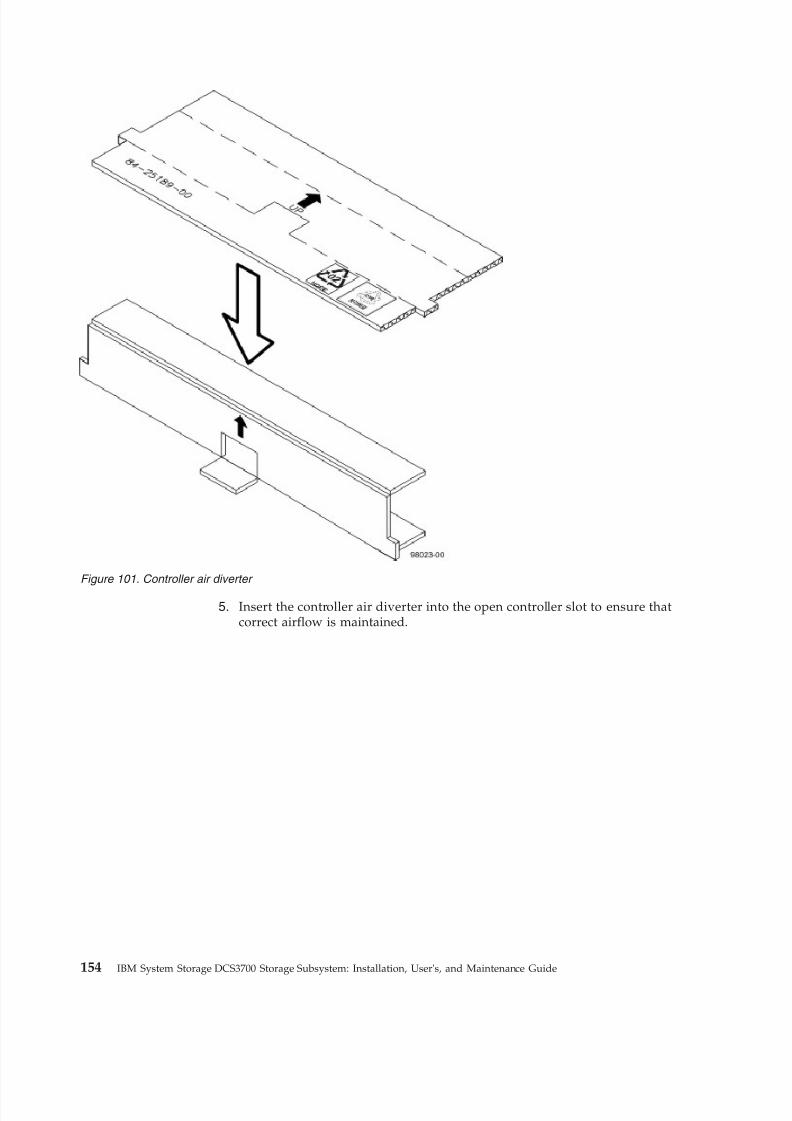
8/9/2019 Installation, User's, And Maintenance
http://slidepdf.com/reader/full/installation-users-and-maintenance 172/262
5. Insert the controller air diverter into the open controller slot to ensure thatcorrect airflow is maintained.
Figure 101. Controller air diverter
154 IBM System Storage DCS3700 Storage Subsystem: Installation, User's, and Maintenance Guide
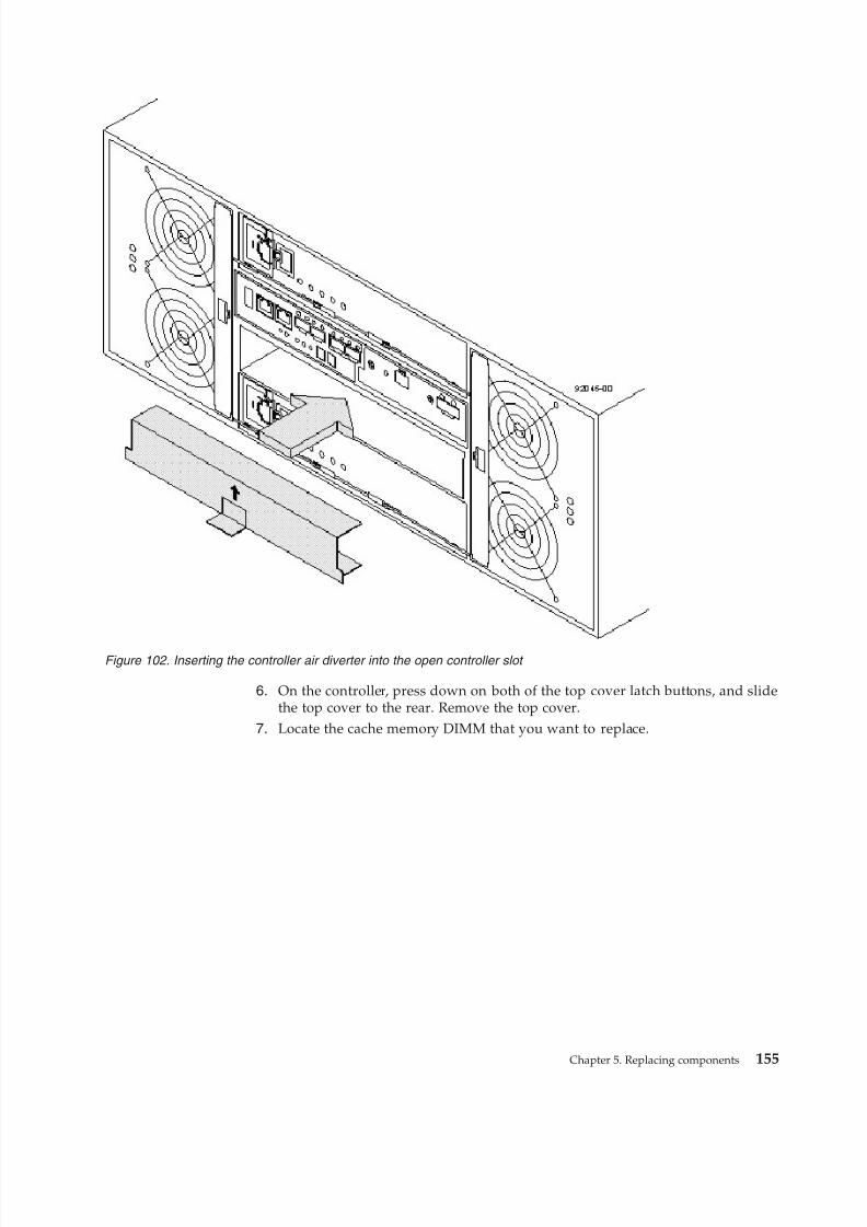
8/9/2019 Installation, User's, And Maintenance
http://slidepdf.com/reader/full/installation-users-and-maintenance 173/262
6. On the controller, press down on both of the top cover latch buttons, and slidethe top cover to the rear. Remove the top cover.
7. Locate the cache memory DIMM that you want to replace.
Figure 102. Inserting the controller air diverter into the open controller slot
Chapter 5. Replacing components 155
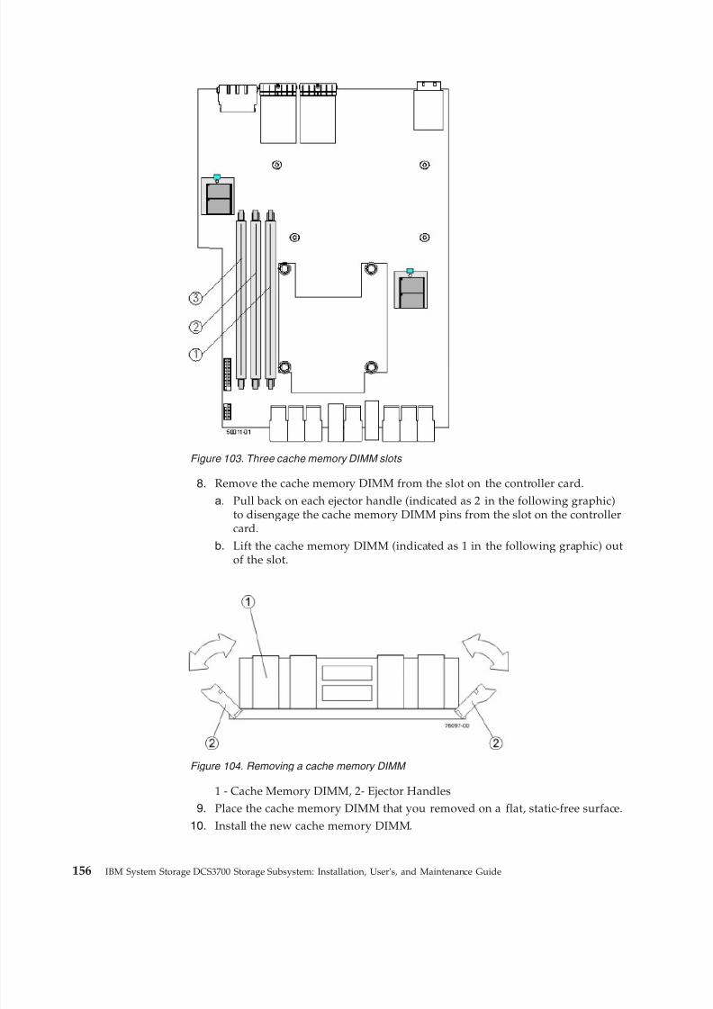
8/9/2019 Installation, User's, And Maintenance
http://slidepdf.com/reader/full/installation-users-and-maintenance 174/262
8. Remove the cache memory DIMM from the slot on the controller card.
a. Pull back on each ejector handle (indicated as 2 in the following graphic)to disengage the cache memory DIMM pins from the slot on the controller
card.b. Lift the cache memory DIMM (indicated as 1 in the following graphic) out
of the slot.
1 - Cache Memory DIMM, 2- Ejector Handles9. Place the cache memory DIMM that you removed on a flat, static-free surface.
10. Install the new cache memory DIMM.
Figure 103. Three cache memory DIMM slots
Figure 104. Removing a cache memory DIMM
156 IBM System Storage DCS3700 Storage Subsystem: Installation, User's, and Maintenance Guide
8/9/2019 Installation, User's, And Maintenance
http://slidepdf.com/reader/full/installation-users-and-maintenance 175/262
a. Align the new cache memory DIMM in the slot. (The DIMM is notched, soyou can install it in only one direction.)
b. Gently push down on the cache memory DIMM to seat the pins into theslot.The ejector handles rise up as the cache memory DIMM is inserted intothe slot. When these ejector handles are in the vertical position, the cache
memory DIMM is fully engaged and is locked in place.11. Reinstall the top cover on the controller by sliding it forward until the topcover latch buttons click.
12. Remove the controller air diverter.
13. Slide the controller into the controller-drive enclosure. Rotate the release leverstowards the center of the controller to lock it into place.
14. Reconnect all the cables to the appropriate ports on both controllers.15. Use either the GUI or the CLI to bring the controller online.
v From the Hardware pane in the Subsystem management Window,right-click the picture of the controller, and select Advanced > Place >Online.
v
Run the following command:smCLI <DNS-network-name-or-IP-address> -c
“set controller [(a | b)] availability=online”;
16. Check the LEDs on the controller to ensure that the controller is rebootingcorrectly. The seven-segment display shows the sequence OS+ Sd+ blank- toindicate that the controller is performing Start-of-day (SOD) processing. Afterthe controller successfully completes rebooting, the seven-segment displayshows the enclosure ID matching the seven-segment display on the secondcontroller. After this time, you can discover the controller by using the IBMDS Storage Manager. Depending on your type of HIC, you might receive anerror message about a failed host I/O card. If this problem occurs, follow theinstructions in the Recovery Guru.
17. Check the Controller Service Action Required LED, and check all of thecontroller-drive enclosure’s Service Action Required LEDs.v Any of the controller-drive enclosure Service Action Required LEDs are on,
or the Controller Service Action Required LED is on – Check if thecontroller is installed correctly. Reinstall the controller, if necessary. ContactIBM support if it is not resolved.
v All of the Service Action Required LEDs are off, and the Subsystemmanagement Window indicates an Optimal status – Go to the next step.
18. Using the LEDs and the IBM DS Storage Manager, check the status of all of the enclosures in the storage subsystem.
19. If any component has a Needs Attention status, Click Recovery Guru in theSubsystem management Window, and complete the recovery procedure. If the
problem has not been resolved, contact your Technical Support representative.20. Remove the anti-static protection.
21. Gather support data about your storage subsystem by using one of thesemethods:v Use the IBM DS Storage Manager to collect and save a support bundle of
your storage subsystem. From the Subsystem management window, selectMonitor > Health > Collect Support Data. Then name and specify alocation on your system where you want to store the support bundle.
v Use the command line interface (CLI) to run the save storageArraysupportData command to gather comprehensive support data about the
Chapter 5. Replacing components 157
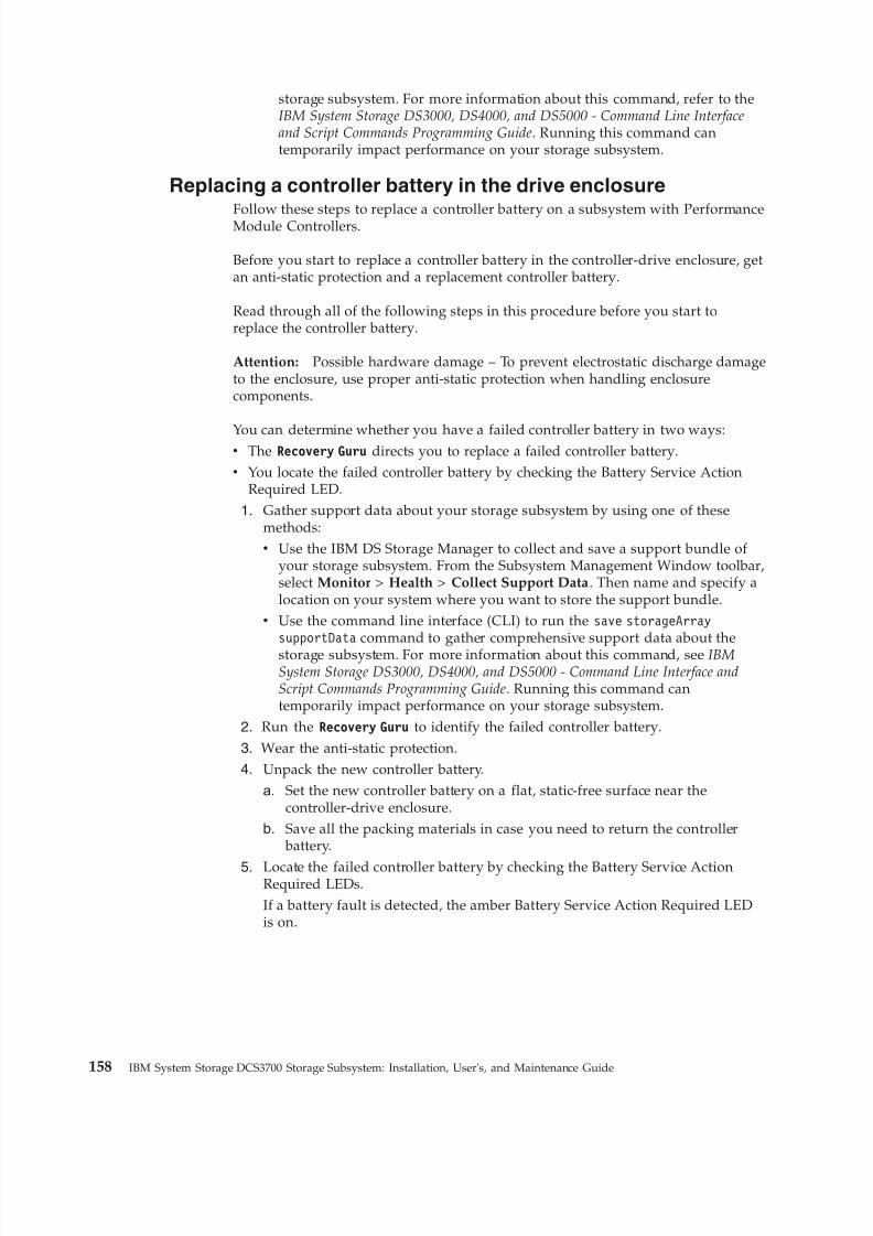
8/9/2019 Installation, User's, And Maintenance
http://slidepdf.com/reader/full/installation-users-and-maintenance 176/262
storage subsystem. For more information about this command, refer to theIBM System Storage DS3000, DS4000, and DS5000 - Command Line Interfaceand Script Commands Programming Guide. Running this command cantemporarily impact performance on your storage subsystem.
Replacing a controller battery in the drive enclosure
Follow these steps to replace a controller battery on a subsystem with PerformanceModule Controllers.
Before you start to replace a controller battery in the controller-drive enclosure, getan anti-static protection and a replacement controller battery.
Read through all of the following steps in this procedure before you start toreplace the controller battery.
Attention: Possible hardware damage – To prevent electrostatic discharge damageto the enclosure, use proper anti-static protection when handling enclosurecomponents.
You can determine whether you have a failed controller battery in two ways:v The Recovery Guru directs you to replace a failed controller battery.v You locate the failed controller battery by checking the Battery Service Action
Required LED.
1. Gather support data about your storage subsystem by using one of thesemethods:v Use the IBM DS Storage Manager to collect and save a support bundle of
your storage subsystem. From the Subsystem Management Window toolbar,select Monitor > Health > Collect Support Data. Then name and specify alocation on your system where you want to store the support bundle.
v Use the command line interface (CLI) to run the save storageArraysupportData command to gather comprehensive support data about thestorage subsystem. For more information about this command, see IBMSystem Storage DS3000, DS4000, and DS5000 - Command Line Interface andScript Commands Programming Guide. Running this command cantemporarily impact performance on your storage subsystem.
2. Run the Recovery Guru to identify the failed controller battery.
3. Wear the anti-static protection.4. Unpack the new controller battery.
a. Set the new controller battery on a flat, static-free surface near thecontroller-drive enclosure.
b. Save all the packing materials in case you need to return the controller battery.
5. Locate the failed controller battery by checking the Battery Service ActionRequired LEDs.If a battery fault is detected, the amber Battery Service Action Required LEDis on.
158 IBM System Storage DCS3700 Storage Subsystem: Installation, User's, and Maintenance Guide
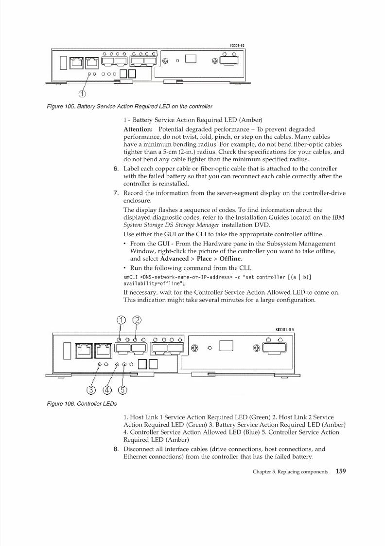
8/9/2019 Installation, User's, And Maintenance
http://slidepdf.com/reader/full/installation-users-and-maintenance 177/262
1 - Battery Service Action Required LED (Amber)Attention: Potential degraded performance – To prevent degradedperformance, do not twist, fold, pinch, or step on the cables. Many cableshave a minimum bending radius. For example, do not bend fiber-optic cablestighter than a 5-cm (2-in.) radius. Check the specifications for your cables, anddo not bend any cable tighter than the minimum specified radius.
6. Label each copper cable or fiber-optic cable that is attached to the controllerwith the failed battery so that you can reconnect each cable correctly after thecontroller is reinstalled.
7. Record the information from the seven-segment display on the controller-driveenclosure.The display flashes a sequence of codes. To find information about thedisplayed diagnostic codes, refer to the Installation Guides located on the IBMSystem Storage DS Storage Manager installation DVD.Use either the GUI or the CLI to take the appropriate controller offline.v From the GUI - From the Hardware pane in the Subsystem Management
Window, right-click the picture of the controller you want to take offline,and select Advanced > Place > Offline.
v Run the following command from the CLI.smCLI <DNS-network-name-or-IP-address> -c “set controller [(a | b)]availability=offline”;
If necessary, wait for the Controller Service Action Allowed LED to come on.This indication might take several minutes for a large configuration.
1. Host Link 1 Service Action Required LED (Green) 2. Host Link 2 ServiceAction Required LED (Green) 3. Battery Service Action Required LED (Amber)4. Controller Service Action Allowed LED (Blue) 5. Controller Service ActionRequired LED (Amber)
8. Disconnect all interface cables (drive connections, host connections, andEthernet connections) from the controller that has the failed battery.
Figure 105. Battery Service Action Required LED on the controller
Figure 106. Controller LEDs
Chapter 5. Replacing components 159
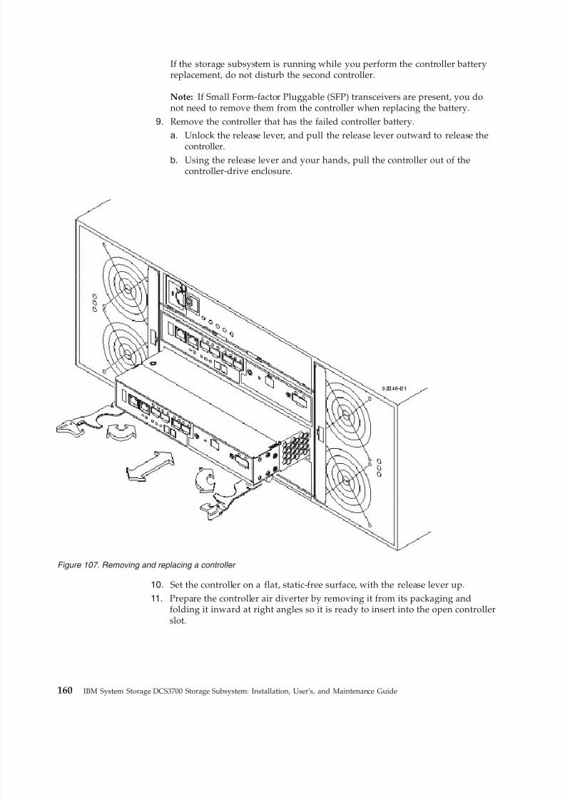
8/9/2019 Installation, User's, And Maintenance
http://slidepdf.com/reader/full/installation-users-and-maintenance 178/262
If the storage subsystem is running while you perform the controller batteryreplacement, do not disturb the second controller.
Note: If Small Form-factor Pluggable (SFP) transceivers are present, you donot need to remove them from the controller when replacing the battery.
9. Remove the controller that has the failed controller battery.
a. Unlock the release lever, and pull the release lever outward to release thecontroller.b. Using the release lever and your hands, pull the controller out of the
controller-drive enclosure.
10. Set the controller on a flat, static-free surface, with the release lever up.11. Prepare the controller air diverter by removing it from its packaging and
folding it inward at right angles so it is ready to insert into the open controllerslot.
Figure 107. Removing and replacing a controller
160 IBM System Storage DCS3700 Storage Subsystem: Installation, User's, and Maintenance Guide
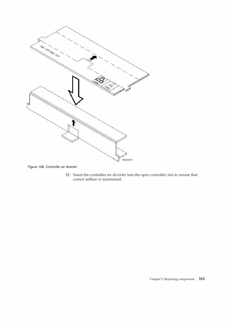
8/9/2019 Installation, User's, And Maintenance
http://slidepdf.com/reader/full/installation-users-and-maintenance 179/262
12. Insert the controller air diverter into the open controller slot to ensure thatcorrect airflow is maintained.
Figure 108. Controller air diverter
Chapter 5. Replacing components 161
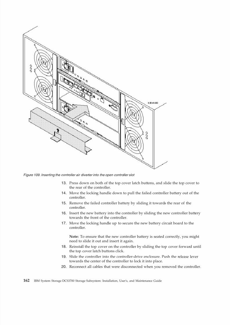
8/9/2019 Installation, User's, And Maintenance
http://slidepdf.com/reader/full/installation-users-and-maintenance 180/262
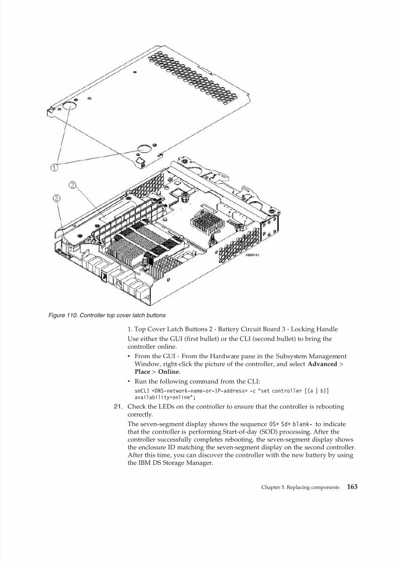
8/9/2019 Installation, User's, And Maintenance
http://slidepdf.com/reader/full/installation-users-and-maintenance 181/262
1. Top Cover Latch Buttons 2 - Battery Circuit Board 3 - Locking HandleUse either the GUI (first bullet) or the CLI (second bullet) to bring thecontroller online.v From the GUI - From the Hardware pane in the Subsystem Management
Window, right-click the picture of the controller, and select Advanced >Place > Online.
v Run the following command from the CLI:smCLI <DNS-network-name-or-IP-address> -c “set controller [(a | b)]availability=online”;
21. Check the LEDs on the controller to ensure that the controller is rebootingcorrectly.The seven-segment display shows the sequence OS+ Sd+ blank- to indicatethat the controller is performing Start-of-day (SOD) processing. After thecontroller successfully completes rebooting, the seven-segment display showsthe enclosure ID matching the seven-segment display on the second controller.After this time, you can discover the controller with the new battery by usingthe IBM DS Storage Manager.
Figure 110. Controller top cover latch buttons
Chapter 5. Replacing components 163
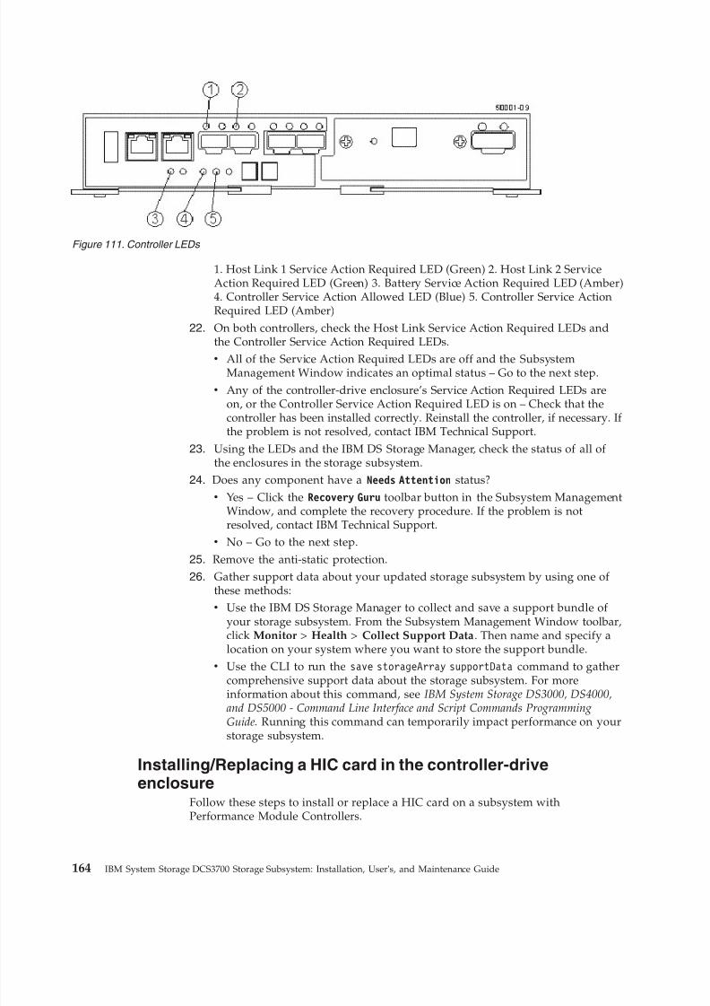
8/9/2019 Installation, User's, And Maintenance
http://slidepdf.com/reader/full/installation-users-and-maintenance 182/262
1. Host Link 1 Service Action Required LED (Green) 2. Host Link 2 ServiceAction Required LED (Green) 3. Battery Service Action Required LED (Amber)4. Controller Service Action Allowed LED (Blue) 5. Controller Service ActionRequired LED (Amber)
22. On both controllers, check the Host Link Service Action Required LEDs andthe Controller Service Action Required LEDs.v All of the Service Action Required LEDs are off and the Subsystem
Management Window indicates an optimal status – Go to the next step.v Any of the controller-drive enclosure’s Service Action Required LEDs are
on, or the Controller Service Action Required LED is on – Check that thecontroller has been installed correctly. Reinstall the controller, if necessary. If the problem is not resolved, contact IBM Technical Support.
23. Using the LEDs and the IBM DS Storage Manager, check the status of all of the enclosures in the storage subsystem.
24. Does any component have a Needs Attention status?v Yes – Click the Recovery Guru toolbar button in the Subsystem Management
Window, and complete the recovery procedure. If the problem is not
resolved, contact IBM Technical Support.v No – Go to the next step.
25. Remove the anti-static protection.26. Gather support data about your updated storage subsystem by using one of
these methods:v Use the IBM DS Storage Manager to collect and save a support bundle of
your storage subsystem. From the Subsystem Management Window toolbar,click Monitor > Health > Collect Support Data. Then name and specify alocation on your system where you want to store the support bundle.
v Use the CLI to run the save storageArray supportData command to gathercomprehensive support data about the storage subsystem. For moreinformation about this command, see IBM System Storage DS3000, DS4000,
and DS5000 - Command Line Interface and Script Commands ProgrammingGuide. Running this command can temporarily impact performance on yourstorage subsystem.
Installing/Replacing a HIC card in the controller-driveenclosure
Follow these steps to install or replace a HIC card on a subsystem withPerformance Module Controllers.
Figure 111. Controller LEDs
164 IBM System Storage DCS3700 Storage Subsystem: Installation, User's, and Maintenance Guide
8/9/2019 Installation, User's, And Maintenance
http://slidepdf.com/reader/full/installation-users-and-maintenance 183/262
Note: Only a qualified service technician should perform this procedure, orequipment damage might result.
Use this procedure to replace a host interface card (HIC) that has failed. Thereplacement HIC can have Fibre Channel connections. Both controllers in a duplexcontroller-drive enclosure must have the same arrangement of HICs. Eachcontroller must have the same type of HIC in the same relative position as the
other controller.
Note: Ensure that you have the correct host interface card (HIC), SmallForm-factor Pluggable (SFP) transceivers, and host bus adapters, or host channeladapters. Because you are replacing one HIC with a potentially different type of HIC, you might not be able to reuse the SFP transceivers. If both controllers in aduplex controller-drive enclosure are powered up at the same time with differenttypes of HICs, a mismatch results that causes both controllers to lock down (shutdown and stop operating). If one controller is already running, and you replace thealternate controller with a different HIC, then only the replacement controller locksdown, and the running controller remains operational.
Before you upgrade or replace a HIC, get an anti-static protection, and a new HIC.
1. Gather support data about your storage subsystem by using one of thesemethods:v Use the storage management software to collect and save a support bundle
of your storage subsystem. From the Subsystem Management Window,select Monitor > Health > Collect Support Data. Then name and specify alocation on your system where you want to store the support bundle.
v Use the command line interface (CLI) to run the save storageArraysupportData command to gather comprehensive support data about thestorage subsystem. For more information about this command, refer to theIBM System Storage DS3000, DS4000, and DS5000 - Command Line Interfaceand Script Commands Programming Guide. Running this command cantemporarily impact performance on your storage subsystem.
2. Run the Recovery Guru to identify the failed HIC.3. Wear the anti-static protection.4. Locate the controller with the failed HIC by checking the Controller Service
Action Required LEDs. If a fault is detected, the amber Controller ServiceAction Required LED is on. If you can safely remove the controller, the blueController Service Action Allowed LED is on.
Chapter 5. Replacing components 165
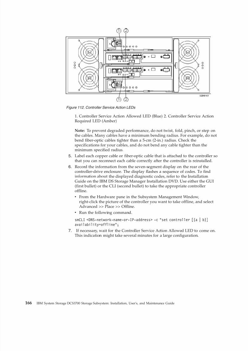
8/9/2019 Installation, User's, And Maintenance
http://slidepdf.com/reader/full/installation-users-and-maintenance 184/262
1. Controller Service Action Allowed LED (Blue) 2. Controller Service Action
Required LED (Amber)Note: To prevent degraded performance, do not twist, fold, pinch, or step onthe cables. Many cables have a minimum bending radius. For example, do not
bend fiber-optic cables tighter than a 5-cm (2-in.) radius. Check thespecifications for your cables, and do not bend any cable tighter than theminimum specified radius.
5. Label each copper cable or fiber-optic cable that is attached to the controller sothat you can reconnect each cable correctly after the controller is reinstalled.
6. Record the information from the seven-segment display on the rear of thecontroller-drive enclosure. The display flashes a sequence of codes. To findinformation about the displayed diagnostic codes, refer to the InstallationGuide on the IBM DS Storage Manager Installation DVD. Use either the GUI(first bullet) or the CLI (second bullet) to take the appropriate controlleroffline.v From the Hardware pane in the Subsystem Management Window,
right-click the picture of the controller you want to take offline, and selectAdvanced >> Place >> Offline.
v Run the following command.
smCLI <DNS-network-name-or-IP-address> -c “set controller [(a | b)]availability=offline”;
7. If necessary, wait for the Controller Service Action Allowed LED to come on.This indication might take several minutes for a large configuration.
Figure 112. Controller Service Action LEDs
166 IBM System Storage DCS3700 Storage Subsystem: Installation, User's, and Maintenance Guide
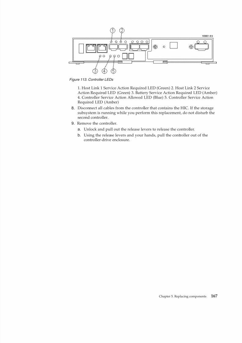
8/9/2019 Installation, User's, And Maintenance
http://slidepdf.com/reader/full/installation-users-and-maintenance 185/262
1. Host Link 1 Service Action Required LED (Green) 2. Host Link 2 ServiceAction Required LED (Green) 3. Battery Service Action Required LED (Amber)4. Controller Service Action Allowed LED (Blue) 5. Controller Service ActionRequired LED (Amber)
8. Disconnect all cables from the controller that contains the HIC. If the storagesubsystem is running while you perform this replacement, do not disturb thesecond controller.
9. Remove the controller.
a. Unlock and pull out the release levers to release the controller.b. Using the release levers and your hands, pull the controller out of the
controller-drive enclosure.
Figure 113. Controller LEDs
Chapter 5. Replacing components 167
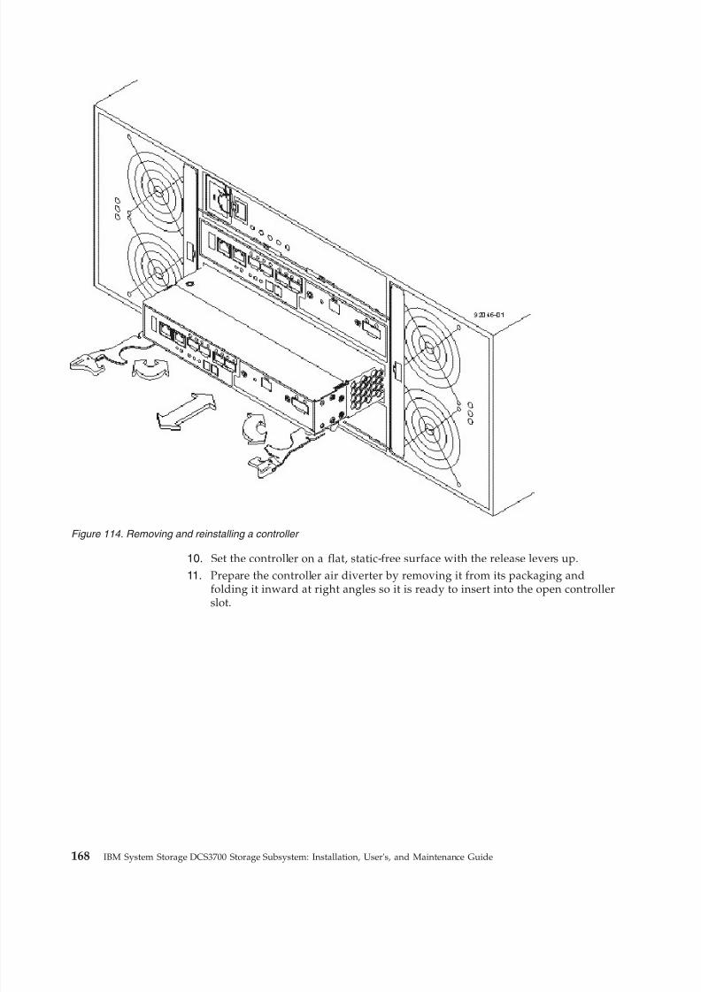
8/9/2019 Installation, User's, And Maintenance
http://slidepdf.com/reader/full/installation-users-and-maintenance 186/262
10. Set the controller on a flat, static-free surface with the release levers up.11. Prepare the controller air diverter by removing it from its packaging and
folding it inward at right angles so it is ready to insert into the open controllerslot.
Figure 114. Removing and reinstalling a controller
168 IBM System Storage DCS3700 Storage Subsystem: Installation, User's, and Maintenance Guide
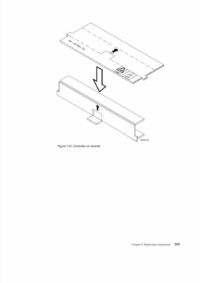
8/9/2019 Installation, User's, And Maintenance
http://slidepdf.com/reader/full/installation-users-and-maintenance 187/262
Figure 115. Controller air diverter
Chapter 5. Replacing components 169
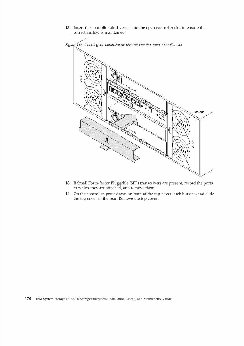
8/9/2019 Installation, User's, And Maintenance
http://slidepdf.com/reader/full/installation-users-and-maintenance 188/262
12. Insert the controller air diverter into the open controller slot to ensure thatcorrect airflow is maintained.
13. If Small Form-factor Pluggable (SFP) transceivers are present, record the portsto which they are attached, and remove them.
14. On the controller, press down on both of the top cover latch buttons, and slidethe top cover to the rear. Remove the top cover.
Figure 116. Inserting the controller air diverter into the open controller slot
170 IBM System Storage DCS3700 Storage Subsystem: Installation, User's, and Maintenance Guide
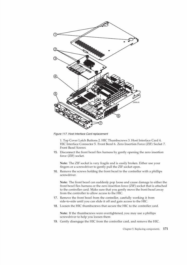
8/9/2019 Installation, User's, And Maintenance
http://slidepdf.com/reader/full/installation-users-and-maintenance 189/262
1. Top Cover Latch Buttons 2. HIC Thumbscrews 3. Host Interface Card 4.HIC Interface Connector 5. Front Bezel 6. Zero Insertion Force (ZIF) Socket 7.Front Bezel Screws
15. Disconnect the front bezel flex harness by gently opening the zero insertionforce (ZIF) socket.
Note: The ZIF socket is very fragile and is easily broken. Either use yourfingers or a screwdriver to gently pull the ZIF socket open.
16. Remove the screws holding the front bezel to the controller with a phillipsscrewdriver.
Note: The front bezel can suddenly pop loose and cause damage to either the
front bezel flex harness or the zero insertion force (ZIF) socket that is attachedto the controller card. Make sure that you gently move the front bezel awayfrom the controller to allow access to the HIC.
17. Remove the front bezel from the controller, carefully working it fromside-to-side until you can slide it off and gain access to the HIC.
18. Loosen the HIC thumbscrews that secure the HIC to the controller card.
Note: If the thumbscrews were overtightened, you may use a phillipsscrewdriver to help you loosen them
19. Gently disengage the HIC from the controller card, and remove the HIC.
Figure 117. Host Interface Card replacement
Chapter 5. Replacing components 171
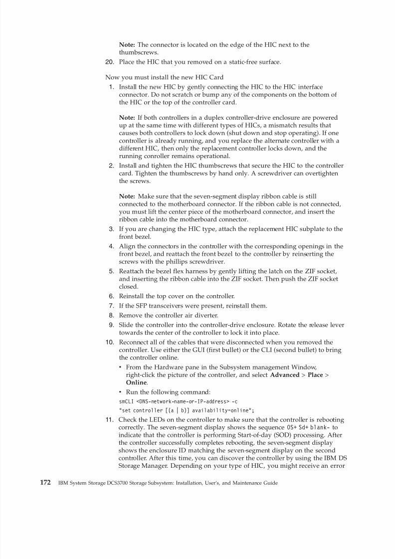
8/9/2019 Installation, User's, And Maintenance
http://slidepdf.com/reader/full/installation-users-and-maintenance 190/262
Note: The connector is located on the edge of the HIC next to thethumbscrews.
20. Place the HIC that you removed on a static-free surface.
Now you must install the new HIC Card1. Install the new HIC by gently connecting the HIC to the HIC interface
connector. Do not scratch or bump any of the components on the bottom of the HIC or the top of the controller card.
Note: If both controllers in a duplex controller-drive enclosure are poweredup at the same time with different types of HICs, a mismatch results thatcauses both controllers to lock down (shut down and stop operating). If onecontroller is already running, and you replace the alternate controller with adifferent HIC, then only the replacement controller locks down, and therunning conroller remains operational.
2. Install and tighten the HIC thumbscrews that secure the HIC to the controllercard. Tighten the thumbscrews by hand only. A screwdriver can overtightenthe screws.
Note: Make sure that the seven-segment display ribbon cable is stillconnected to the motherboard connector. If the ribbon cable is not connected,you must lift the center piece of the motherboard connector, and insert theribbon cable into the motherboard connector.
3. If you are changing the HIC type, attach the replacement HIC subplate to thefront bezel.
4. Align the connectors in the controller with the corresponding openings in thefront bezel, and reattach the front bezel to the controller by reinserting thescrews with the phillips screwdriver.
5. Reattach the bezel flex harness by gently lifting the latch on the ZIF socket,and inserting the ribbon cable into the ZIF socket. Then push the ZIF socketclosed.
6. Reinstall the top cover on the controller.7. If the SFP transceivers were present, reinstall them.8. Remove the controller air diverter.
9. Slide the controller into the controller-drive enclosure. Rotate the release levertowards the center of the controller to lock it into place.
10. Reconnect all of the cables that were disconnected when you removed thecontroller. Use either the GUI (first bullet) or the CLI (second bullet) to bringthe controller online.v From the Hardware pane in the Subsystem management Window,
right-click the picture of the controller, and select Advanced > Place >Online.
v Run the following command:smCLI <DNS-network-name-or-IP-address> -c
“set controller [(a | b)] availability=online”;
11. Check the LEDs on the controller to make sure that the controller is rebootingcorrectly. The seven-segment display shows the sequence OS+ Sd+ blank- toindicate that the controller is performing Start-of-day (SOD) processing. Afterthe controller successfully completes rebooting, the seven-segment displayshows the enclosure ID matching the seven-segment display on the secondcontroller. After this time, you can discover the controller by using the IBM DSStorage Manager. Depending on your type of HIC, you might receive an error
172 IBM System Storage DCS3700 Storage Subsystem: Installation, User's, and Maintenance Guide
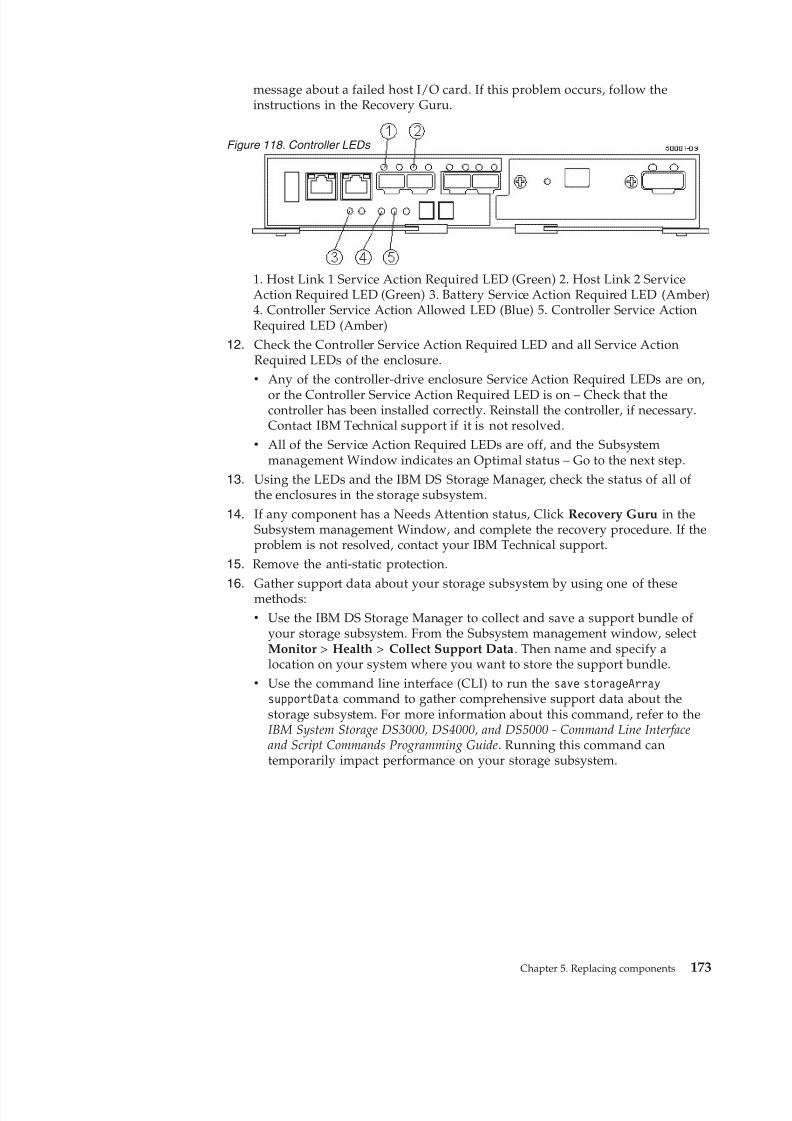
8/9/2019 Installation, User's, And Maintenance
http://slidepdf.com/reader/full/installation-users-and-maintenance 191/262
message about a failed host I/O card. If this problem occurs, follow theinstructions in the Recovery Guru.
1. Host Link 1 Service Action Required LED (Green) 2. Host Link 2 ServiceAction Required LED (Green) 3. Battery Service Action Required LED (Amber)4. Controller Service Action Allowed LED (Blue) 5. Controller Service ActionRequired LED (Amber)
12. Check the Controller Service Action Required LED and all Service ActionRequired LEDs of the enclosure.v Any of the controller-drive enclosure Service Action Required LEDs are on,
or the Controller Service Action Required LED is on – Check that thecontroller has been installed correctly. Reinstall the controller, if necessary.Contact IBM Technical support if it is not resolved.
v All of the Service Action Required LEDs are off, and the Subsystemmanagement Window indicates an Optimal status – Go to the next step.
13. Using the LEDs and the IBM DS Storage Manager, check the status of all of the enclosures in the storage subsystem.
14. If any component has a Needs Attention status, Click Recovery Guru in theSubsystem management Window, and complete the recovery procedure. If theproblem is not resolved, contact your IBM Technical support.
15. Remove the anti-static protection.
16. Gather support data about your storage subsystem by using one of thesemethods:v Use the IBM DS Storage Manager to collect and save a support bundle of
your storage subsystem. From the Subsystem management window, selectMonitor > Health > Collect Support Data. Then name and specify alocation on your system where you want to store the support bundle.
v Use the command line interface (CLI) to run the save storageArraysupportData command to gather comprehensive support data about thestorage subsystem. For more information about this command, refer to theIBM System Storage DS3000, DS4000, and DS5000 - Command Line Interfaceand Script Commands Programming Guide. Running this command cantemporarily impact performance on your storage subsystem.
Figure 118. Controller LEDs
Chapter 5. Replacing components 173

8/9/2019 Installation, User's, And Maintenance
http://slidepdf.com/reader/full/installation-users-and-maintenance 192/262
174 IBM System Storage DCS3700 Storage Subsystem: Installation, User's, and Maintenance Guide
8/9/2019 Installation, User's, And Maintenance
http://slidepdf.com/reader/full/installation-users-and-maintenance 193/262
Chapter 6. Hardware maintenance
This section contains information to help you solve some of the simpler problemsthat you might have with your storage subsystem.
It contains the problem indicators and error messages along with suggested actionsto take to resolve the problem.
For instructions on how to obtain service and technical assistance for your storagesubsystem and other IBM products, see “Getting information, help, and service” onpage xvi.
General checkout
You can carry out a general check to diagnose problems.
Use the indicator lights, the diagnostics and test information, the symptom-to-FRUindex, and the connected server HMM to diagnose problems.
Solving problems
This section contains information to help you solve some of the problems youmight have with your DCS3700 storage system or DCS3700 expansion enclosure.
The following table contains the problem, symptoms and error messages, alongwith suggested actions to take to resolve problems.
Always use the DS Storage Manager client to diagnose storage subsystemproblems and component failures and find solutions to problems that have definite
symptoms.
You can use the following table, which contains the problem symptoms and errormessages, along with suggested actions as a guide for troubleshooting problems inaddition to the DS Storage Manager Recovery Guru in the Subsystem Managementwindow. Do not depend solely on this table for a FRU replacement decision.
Troubleshooting problems in the DCS3700 storage subsystemA table lists the typical problems along with the possible cause and solution, andthe affected component.
© Copyright IBM Corp. 2011, 2013 175
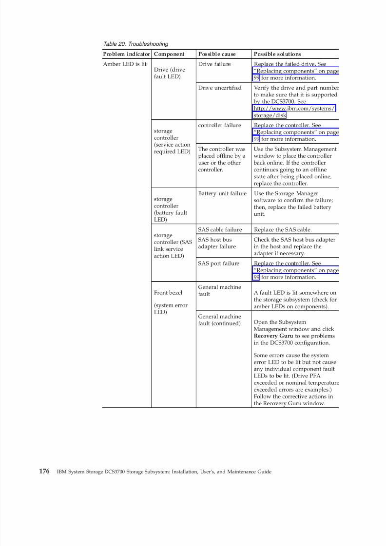
8/9/2019 Installation, User's, And Maintenance
http://slidepdf.com/reader/full/installation-users-and-maintenance 194/262
Table 20. Troubleshooting
Problem indicator Component Possible cause Possible solutions
Amber LED is litDrive (drivefault LED)
Drive failure Replace the failed drive. See“Replacing components” on page99 for more information.
Drive uncertified Verify the drive and part number
to make sure that it is supported by the DCS3700. Seehttp://www.ibm.com/systems/storage/disk
storagecontroller(service actionrequired LED)
controller failure Replace the controller. See“Replacing components” on page99 for more information.
The controller wasplaced offline by auser or the othercontroller.
Use the Subsystem Managementwindow to place the controller back online. If the controllercontinues going to an offlinestate after being placed online,replace the controller.
storagecontroller(battery faultLED)
Battery unit failure Use the Storage Managersoftware to confirm the failure;then, replace the failed batteryunit.
storagecontroller (SASlink serviceaction LED)
SAS cable failure Replace the SAS cable.
SAS host busadapter failure
Check the SAS host bus adapterin the host and replace theadapter if necessary.
SAS port failure Replace the controller. See“Replacing components” on page99 for more information.
Front bezel
(system errorLED)
General machinefault A fault LED is lit somewhere on
the storage subsystem (check foramber LEDs on components).
General machinefault (continued) Open the Subsystem
Management window and clickRecovery Guru to see problemsin the DCS3700 configuration.
Some errors cause the systemerror LED to be lit but not causeany individual component faultLEDs to be lit. (Drive PFA
exceeded or nominal temperatureexceeded errors are examples.)Follow the corrective actions inthe Recovery Guru window.
176 IBM System Storage DCS3700 Storage Subsystem: Installation, User's, and Maintenance Guide
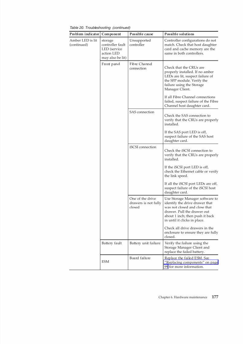
8/9/2019 Installation, User's, And Maintenance
http://slidepdf.com/reader/full/installation-users-and-maintenance 195/262
Table 20. Troubleshooting (continued)
Problem indicator Component Possible cause Possible solutions
Amber LED is lit(continued)
storagecontroller faultLED (serviceaction LEDmay also be lit)
Unsupportedcontroller
Controller configurations do notmatch. Check that host daughtercard and cache memory are thesame in both controllers.
Front panel Fibre Channelconnection Check that the CRUs are
properly installed. If no amberLEDs are lit, suspect failure of the SFP module. Verify thefailure using the StorageManager Client.
If all Fibre Channel connectionsfailed, suspect failure of the FibreChannel host daughter card.
SAS connectionCheck the SAS connection to
verify that the CRUs are properlyinstalled.
If the SAS port LED is off,suspect failure of the SAS hostdaughter card.
iSCSI connectionCheck the iSCSI connection toverify that the CRUs are properlyinstalled.
If the iSCSI port LED is off,check the Ethernet cable or verifythe link speed.
If all the iSCSI port LEDs are off,suspect failure of the iSCSI hostdaughter card.
One of the drivedrawers is not fullyclosed
Use Storage Manager software toidentify the drive drawer thatwas not closed and close thatdrawer. Pull the drawer outabout 1 inch; then push it backin until it clicks in place.
Check all drive drawers in theenclosure to ensure they are fullyclosed.
Battery fault Battery unit failure Verify the failure using theStorage Manager Client andreplace the failed battery.
ESMBoard failure Replace the failed ESM. See
“Replacing components” on page99 for more information.
Chapter 6. Hardware maintenance 177
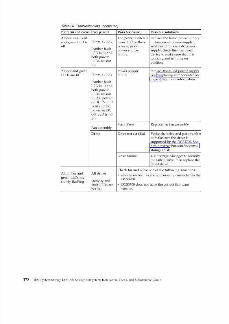
8/9/2019 Installation, User's, And Maintenance
http://slidepdf.com/reader/full/installation-users-and-maintenance 196/262
Table 20. Troubleshooting (continued)
Problem indicator Component Possible cause Possible solutions
Amber LED is litand green LED isoff
Power supply
(Amber faultLED is lit and
both powerLEDs are notlit)
The power switch isturned off or thereis an ac or dcpower sourcefailure.
Replace the failed power supplyor turn on all power-supplyswitches. If this is a dc powersupply, check the disconnectdevice to make sure that it isworking and is in the onposition.
Amber and greenLEDs are lit Power supply
(Amber faultLED is lit and both powerLEDs are notlit, AC poweror DC IN LEDis lit and DCpower or DC
out LED is notlit)
Power supplyfailure
Replace the failed power supply.See “Replacing components” onpage 99 for more information.
Fan assemblyFan failure Replace the fan assembly.
Drive Drive not certified Verity the drive and part numberto make sure the drive issupported by the DCS3700. Seehttp://www.ibm.com/systems/storage/disk
Drive failure Use Storage Manager to identifythe failed drive; then replace thefailed drive.
All amber andgreen LEDs areslowly flashing
All drives
(activity andfault LEDs arenot lit)
Check for and solve one of the following situations:v storage enclosures are not correctly connected to the
DCS3700.
v DCS3700 does not have the correct firmwareversion.
178 IBM System Storage DCS3700 Storage Subsystem: Installation, User's, and Maintenance Guide
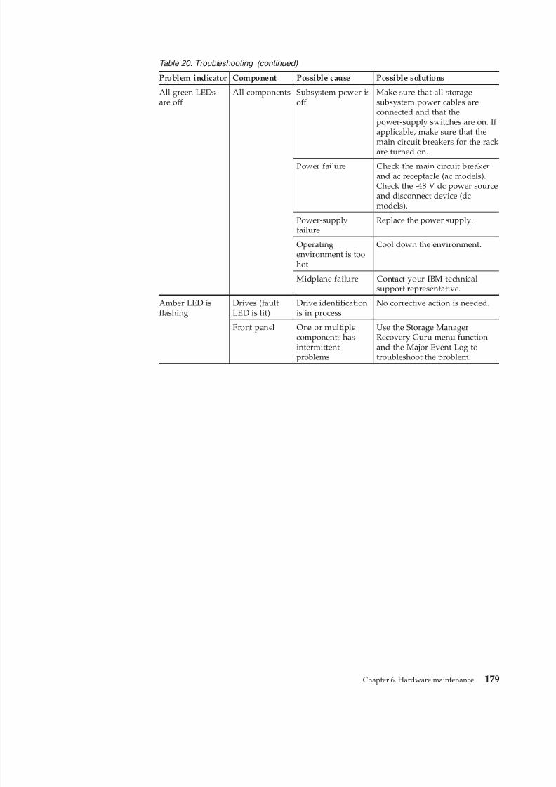
8/9/2019 Installation, User's, And Maintenance
http://slidepdf.com/reader/full/installation-users-and-maintenance 197/262
Table 20. Troubleshooting (continued)
Problem indicator Component Possible cause Possible solutions
All green LEDsare off
All components Subsystem power isoff
Make sure that all storagesubsystem power cables areconnected and that thepower-supply switches are on. If applicable, make sure that themain circuit breakers for the rackare turned on.
Power failure Check the main circuit breakerand ac receptacle (ac models).Check the -48 V dc power sourceand disconnect device (dcmodels).
Power-supplyfailure
Replace the power supply.
Operatingenvironment is toohot
Cool down the environment.
Midplane failure Contact your IBM technicalsupport representative.
Amber LED isflashing
Drives (faultLED is lit)
Drive identificationis in process
No corrective action is needed.
Front panel One or multiplecomponents hasintermittentproblems
Use the Storage ManagerRecovery Guru menu functionand the Major Event Log totroubleshoot the problem.
Chapter 6. Hardware maintenance 179
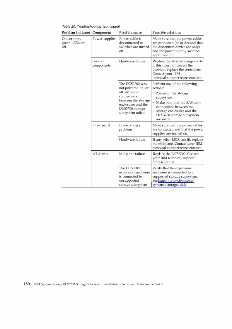
8/9/2019 Installation, User's, And Maintenance
http://slidepdf.com/reader/full/installation-users-and-maintenance 198/262
Table 20. Troubleshooting (continued)
Problem indicator Component Possible cause Possible solutions
One or moregreen LEDs areoff
Power supplies Power cable isdisconnected orswitches are turnedoff
Make sure that the power cablesare connected (ac or dc) and thatthe disconnect device (dc only)and the power-supply switchesare turned on.
Severalcomponents
Hardware failure Replace the affected components.If this does not correct theproblem, replace the controllers.Contact your IBMtechnical-support representative.
The DCS3700 wasnot powered-on, orall SAS cableconnections between the storageenclosures and theDCS3700 storagesubsystem failed.
Perform one of the followingactions:
v Power-on the storagesubsystem.
v Make sure that the SAS cableconnections between thestorage enclosures and the
DCS3700 storage subsystemare made.
Front panel Power supplyproblem
Make sure that the power cablesare connected and that the powersupplies are turned on.
Hardware failure If any other LEDs are lit, replacethe midplane. Contact your IBMtechnical-support representative.
All drives Midplane failure Replace the DCS3700. Contactyour IBM technical-supportrepresentative.
The DCS3700
expansion enclosureis connected tounsupportedstorage subsystem
Verify that the expansion
enclosure is connected to asupported storage subsystem.See http://www.ibm.com/systems/storage/disk
180 IBM System Storage DCS3700 Storage Subsystem: Installation, User's, and Maintenance Guide
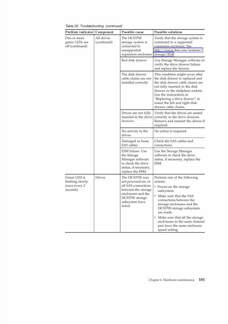
8/9/2019 Installation, User's, And Maintenance
http://slidepdf.com/reader/full/installation-users-and-maintenance 199/262
Table 20. Troubleshooting (continued)
Problem indicator Component Possible cause Possible solutions
One or moregreen LEDs areoff (continued)
All drives(continued)
The DCS3700storage system isconnected tounsupportedexpansion enclosure
Verify that the storage system isconnected to a supportedexpansion enclosure. Seehttp://www.ibm.com/systems/storage/disk
Bad disk drawer Use Storage Manager software toverify the drive drawer failureand replace the drawer.
The disk drawercable chains are notinstalled correctly
This condition might occur afterthe disk drawer is replaced andthe disk drawer cable chains arenot fully inserted in the diskdrawer or the midplane sockets.Use the instructions in“Replacing a drive drawer” toreseat the left and right diskdrawer cable chains.
Drives are not fullyinserted in the drivedrawers
Verify that the drives are seatedcorrectly in the drive drawers.Remove and reinsert the drives if required.
No activity to thedrives
No action is required.
Damaged or looseSAS cables
Check the SAS cables andconnections.
ESM failure. Usethe StorageManager softwareto check the drivestatus, if necessary,replace the ESM.
Use the Storage Managersoftware to check the drivestatus, if necessary, replace theESM.
Green LED isflashing slowly(once every 2seconds)
Drives The DCS3700 wasnot powered-on, orall SAS connections between the storageenclosures and theDCS3700 storagesubsystem havefailed.
Perform one of the followingactions:
v Power-on the storagesubsystem.
v Make sure that the SASconnections between thestorage enclosures and theDCS3700 storage subsystemare made.
v Make sure that all the storageenclosures in the same channel
pair have the same enclosurespeed setting.
Chapter 6. Hardware maintenance 181
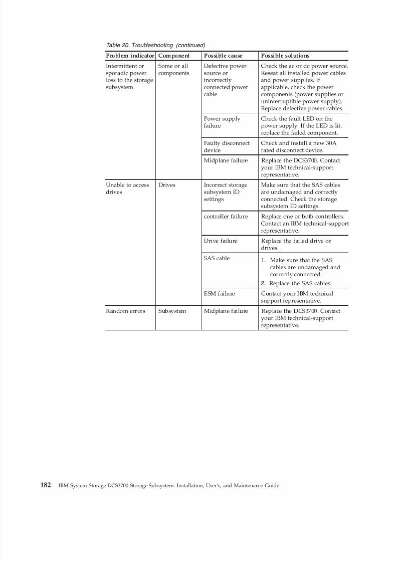
8/9/2019 Installation, User's, And Maintenance
http://slidepdf.com/reader/full/installation-users-and-maintenance 200/262
Table 20. Troubleshooting (continued)
Problem indicator Component Possible cause Possible solutions
Intermittent orsporadic powerloss to the storagesubsystem
Some or allcomponents
Defective powersource orincorrectlyconnected powercable
Check the ac or dc power source.Reseat all installed power cablesand power supplies. If applicable, check the powercomponents (power supplies oruninterruptible power supply).Replace defective power cables.
Power supplyfailure
Check the fault LED on thepower supply. If the LED is lit,replace the failed component.
Faulty disconnectdevice
Check and install a new 30Arated disconnect device.
Midplane failure Replace the DCS3700. Contactyour IBM technical-supportrepresentative.
Unable to accessdrives
Drives Incorrect storagesubsystem IDsettings
Make sure that the SAS cablesare undamaged and correctlyconnected. Check the storagesubsystem ID settings.
controller failure Replace one or both controllers.Contact an IBM technical-supportrepresentative.
Drive failure Replace the failed drive ordrives.
SAS cable 1. Make sure that the SAScables are undamaged andcorrectly connected.
2. Replace the SAS cables.
ESM failure Contact your IBM technicalsupport representative.
Random errors Subsystem Midplane failure Replace the DCS3700. Contactyour IBM technical-supportrepresentative.
182 IBM System Storage DCS3700 Storage Subsystem: Installation, User's, and Maintenance Guide
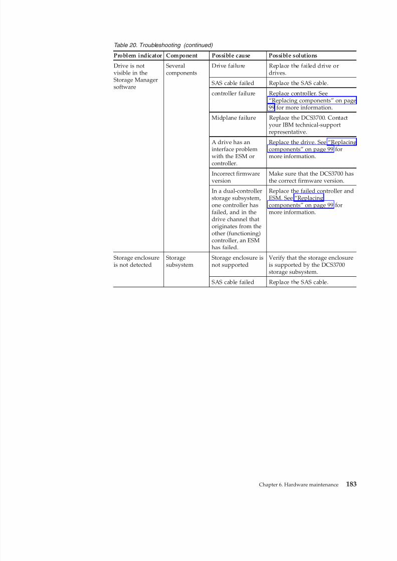
8/9/2019 Installation, User's, And Maintenance
http://slidepdf.com/reader/full/installation-users-and-maintenance 201/262
Table 20. Troubleshooting (continued)
Problem indicator Component Possible cause Possible solutions
Drive is notvisible in theStorage Managersoftware
Severalcomponents
Drive failure Replace the failed drive ordrives.
SAS cable failed Replace the SAS cable.
controller failure Replace controller. See“Replacing components” on page99 for more information.
Midplane failure Replace the DCS3700. Contactyour IBM technical-supportrepresentative.
A drive has aninterface problemwith the ESM orcontroller.
Replace the drive. See “Replacingcomponents” on page 99 formore information.
Incorrect firmwareversion
Make sure that the DCS3700 hasthe correct firmware version.
In a dual-controller
storage subsystem,one controller hasfailed, and in thedrive channel thatoriginates from theother (functioning)controller, an ESMhas failed.
Replace the failed controller and
ESM. See “Replacingcomponents” on page 99 formore information.
Storage enclosureis not detected
Storagesubsystem
Storage enclosure isnot supported
Verify that the storage enclosureis supported by the DCS3700storage subsystem.
SAS cable failed Replace the SAS cable.
Chapter 6. Hardware maintenance 183
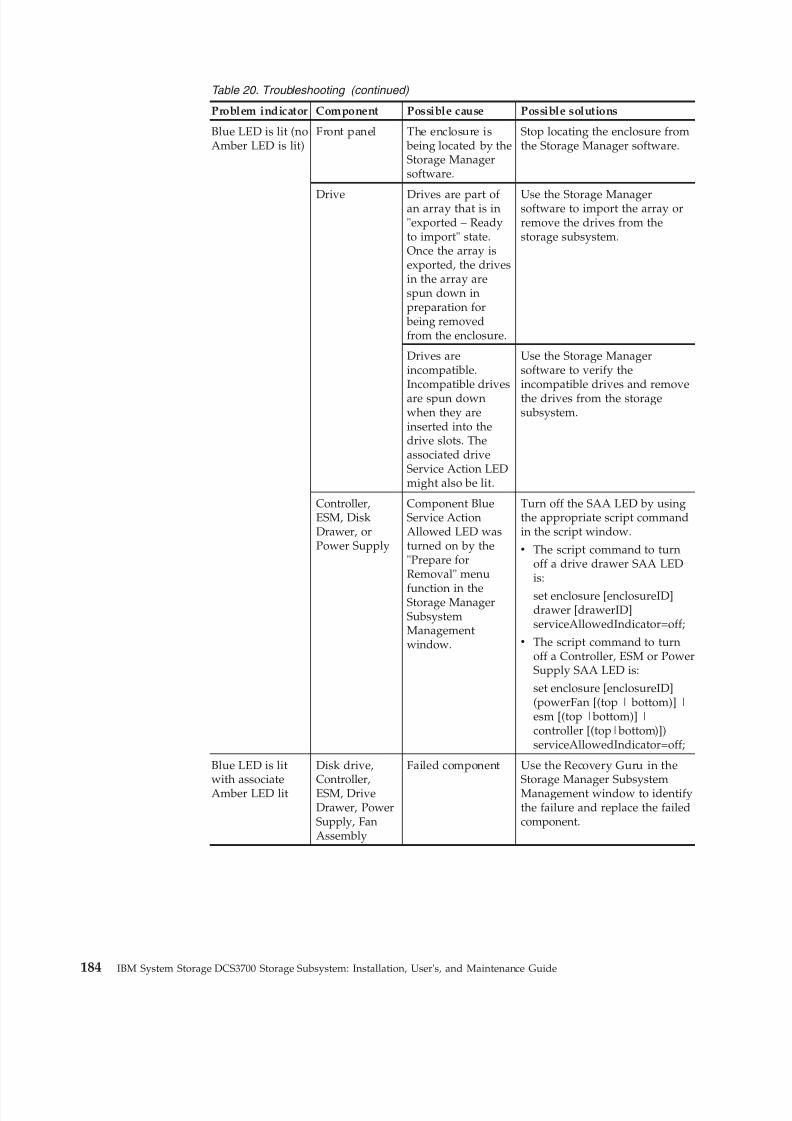
8/9/2019 Installation, User's, And Maintenance
http://slidepdf.com/reader/full/installation-users-and-maintenance 202/262
Table 20. Troubleshooting (continued)
Problem indicator Component Possible cause Possible solutions
Blue LED is lit (noAmber LED is lit)
Front panel The enclosure is being located by theStorage Managersoftware.
Stop locating the enclosure fromthe Storage Manager software.
Drive Drives are part of an array that is in"exported – Readyto import" state.Once the array isexported, the drivesin the array arespun down inpreparation for being removedfrom the enclosure.
Use the Storage Managersoftware to import the array orremove the drives from thestorage subsystem.
Drives areincompatible.Incompatible drivesare spun downwhen they areinserted into thedrive slots. Theassociated driveService Action LEDmight also be lit.
Use the Storage Managersoftware to verify theincompatible drives and removethe drives from the storagesubsystem.
Controller,ESM, DiskDrawer, orPower Supply
Component BlueService ActionAllowed LED wasturned on by the"Prepare forRemoval" menu
function in theStorage ManagerSubsystemManagementwindow.
Turn off the SAA LED by usingthe appropriate script commandin the script window.
v The script command to turnoff a drive drawer SAA LEDis:
set enclosure [enclosureID]drawer [drawerID]serviceAllowedIndicator=off;
v The script command to turnoff a Controller, ESM or PowerSupply SAA LED is:
set enclosure [enclosureID](powerFan [(top | bottom)] |esm [(top |bottom)] |controller [(top|bottom)])serviceAllowedIndicator=off;
Blue LED is lit
with associateAmber LED lit
Disk drive,
Controller,ESM, DriveDrawer, PowerSupply, FanAssembly
Failed component Use the Recovery Guru in the
Storage Manager SubsystemManagement window to identifythe failure and replace the failedcomponent.
184 IBM System Storage DCS3700 Storage Subsystem: Installation, User's, and Maintenance Guide
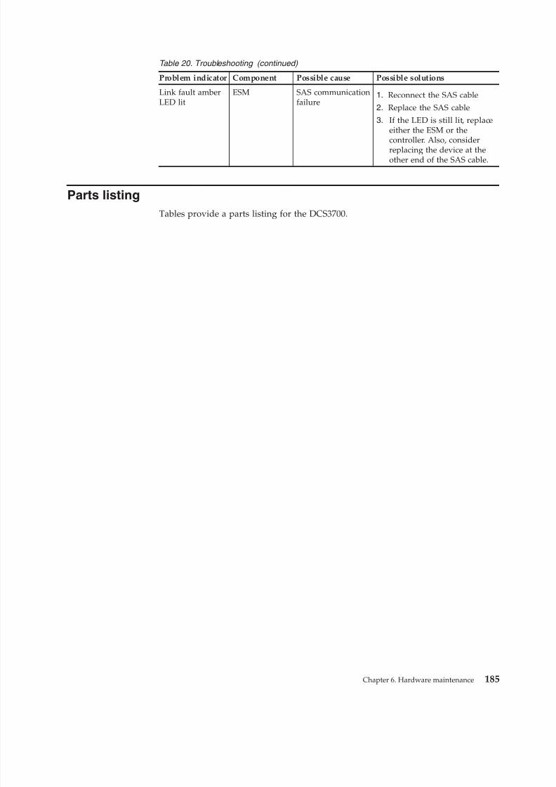
8/9/2019 Installation, User's, And Maintenance
http://slidepdf.com/reader/full/installation-users-and-maintenance 203/262
Table 20. Troubleshooting (continued)
Problem indicator Component Possible cause Possible solutions
Link fault amberLED lit
ESM SAS communicationfailure
1. Reconnect the SAS cable
2. Replace the SAS cable
3. If the LED is still lit, replaceeither the ESM or the
controller. Also, considerreplacing the device at theother end of the SAS cable.
Parts listing
Tables provide a parts listing for the DCS3700.
Chapter 6. Hardware maintenance 185
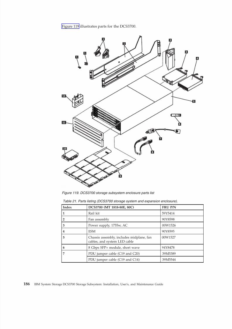
8/9/2019 Installation, User's, And Maintenance
http://slidepdf.com/reader/full/installation-users-and-maintenance 204/262
Figure 119 illustrates parts for the DCS3700.
Table 21. Parts listing (DCS3700 storage system and expansion enclosure) .
Index DCS3700 (MT 1818-80E, 80C) FRU P/N
1 Rail kit 59Y5414
2 Fan assembly 90Y8598
3 Power supply, 1755w, AC 00W1526
4 ESM 90Y85955 Chassis assembly, includes midplane, fan
cables, and system LED cable00W1527
6 8 Gbps SFP+ module, short wave 94Y8478
7 PDU jumper cable (C19 and C20) 39M5389
PDU jumper cable (C19 and C14) 39M5544
Figure 119. DCS3700 storage subsystem enclosure parts list
186 IBM System Storage DCS3700 Storage Subsystem: Installation, User's, and Maintenance Guide
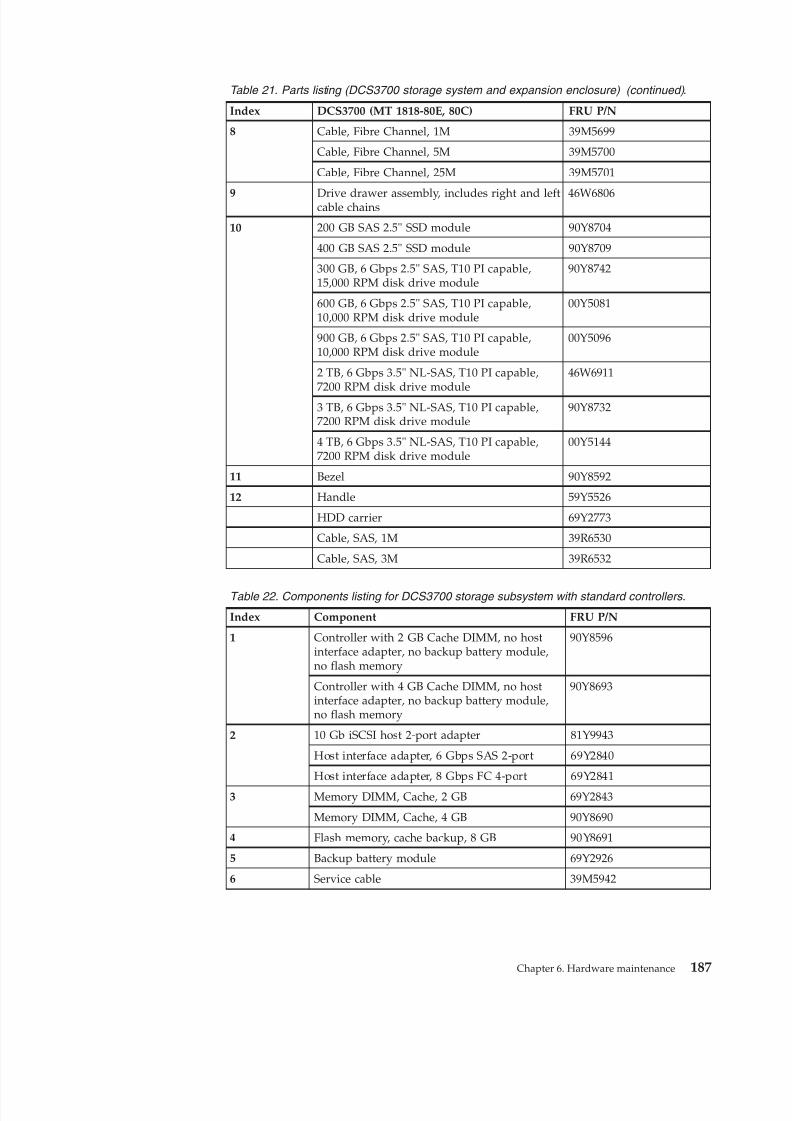
8/9/2019 Installation, User's, And Maintenance
http://slidepdf.com/reader/full/installation-users-and-maintenance 205/262
Table 21. Parts listing (DCS3700 storage system and expansion enclosure) (continued) .
Index DCS3700 (MT 1818-80E, 80C) FRU P/N
8 Cable, Fibre Channel, 1M 39M5699
Cable, Fibre Channel, 5M 39M5700
Cable, Fibre Channel, 25M 39M5701
9 Drive drawer assembly, includes right and leftcable chains 46W6806
10 200 GB SAS 2.5" SSD module 90Y8704
400 GB SAS 2.5" SSD module 90Y8709
300 GB, 6 Gbps 2.5" SAS, T10 PI capable,15,000 RPM disk drive module
90Y8742
600 GB, 6 Gbps 2.5" SAS, T10 PI capable,10,000 RPM disk drive module
00Y5081
900 GB, 6 Gbps 2.5" SAS, T10 PI capable,10,000 RPM disk drive module
00Y5096
2 TB, 6 Gbps 3.5" NL-SAS, T10 PI capable,
7200 RPM disk drive module
46W6911
3 TB, 6 Gbps 3.5" NL-SAS, T10 PI capable,7200 RPM disk drive module
90Y8732
4 TB, 6 Gbps 3.5" NL-SAS, T10 PI capable,7200 RPM disk drive module
00Y5144
11 Bezel 90Y8592
12 Handle 59Y5526
HDD carrier 69Y2773
Cable, SAS, 1M 39R6530
Cable, SAS, 3M 39R6532
Table 22. Components listing for DCS3700 storage subsystem with standard controllers .
Index Component FRU P/N
1 Controller with 2 GB Cache DIMM, no hostinterface adapter, no backup battery module,no flash memory
90Y8596
Controller with 4 GB Cache DIMM, no hostinterface adapter, no backup battery module,no flash memory
90Y8693
2 10 Gb iSCSI host 2-port adapter 81Y9943
Host interface adapter, 6 Gbps SAS 2-port 69Y2840
Host interface adapter, 8 Gbps FC 4-port 69Y2841
3 Memory DIMM, Cache, 2 GB 69Y2843
Memory DIMM, Cache, 4 GB 90Y8690
4 Flash memory, cache backup, 8 GB 90Y8691
5 Backup battery module 69Y2926
6 Service cable 39M5942
Chapter 6. Hardware maintenance 187
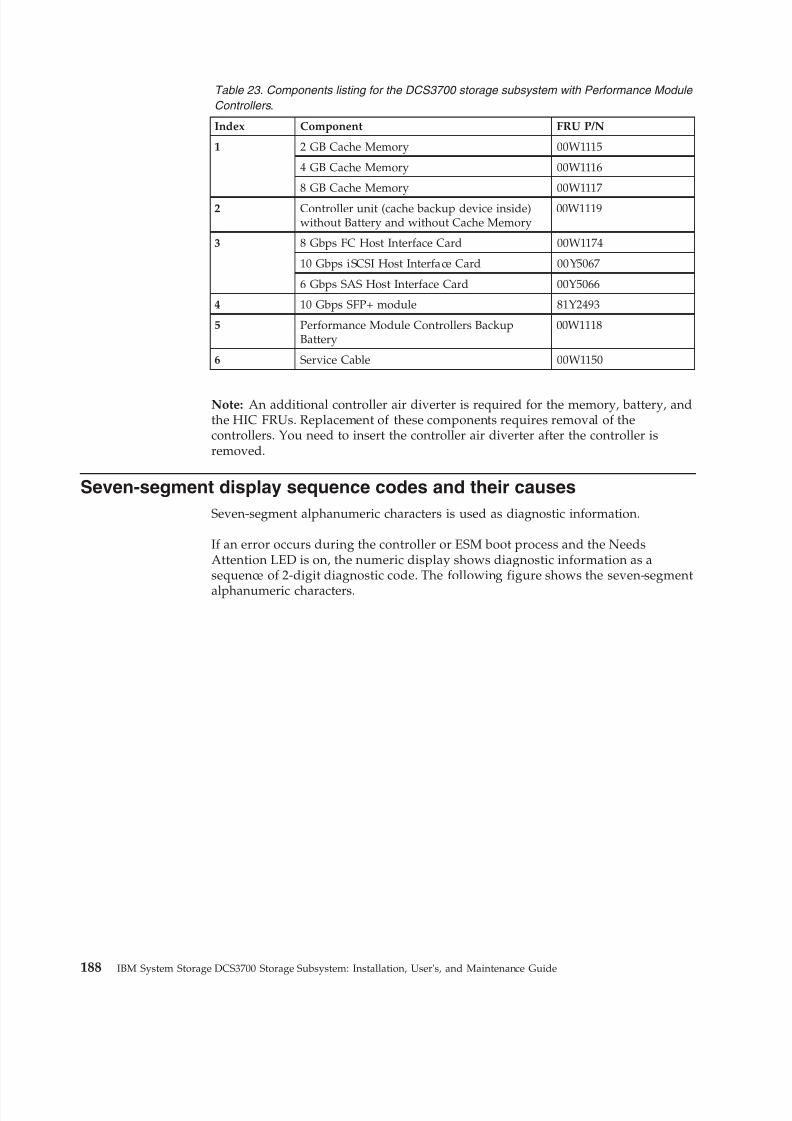
8/9/2019 Installation, User's, And Maintenance
http://slidepdf.com/reader/full/installation-users-and-maintenance 206/262
Table 23. Components listing for the DCS3700 storage subsystem with Performance Module
Controllers .
Index Component FRU P/N
1 2 GB Cache Memory 00W1115
4 GB Cache Memory 00W1116
8 GB Cache Memory 00W1117
2 Controller unit (cache backup device inside)without Battery and without Cache Memory
00W1119
3 8 Gbps FC Host Interface Card 00W1174
10 Gbps iSCSI Host Interface Card 00Y5067
6 Gbps SAS Host Interface Card 00Y5066
4 10 Gbps SFP+ module 81Y2493
5 Performance Module Controllers BackupBattery
00W1118
6 Service Cable 00W1150
Note: An additional controller air diverter is required for the memory, battery, andthe HIC FRUs. Replacement of these components requires removal of thecontrollers. You need to insert the controller air diverter after the controller isremoved.
Seven-segment display sequence codes and their causes
Seven-segment alphanumeric characters is used as diagnostic information.
If an error occurs during the controller or ESM boot process and the NeedsAttention LED is on, the numeric display shows diagnostic information as asequence of 2-digit diagnostic code. The following figure shows the seven-segment
alphanumeric characters.
188 IBM System Storage DCS3700 Storage Subsystem: Installation, User's, and Maintenance Guide
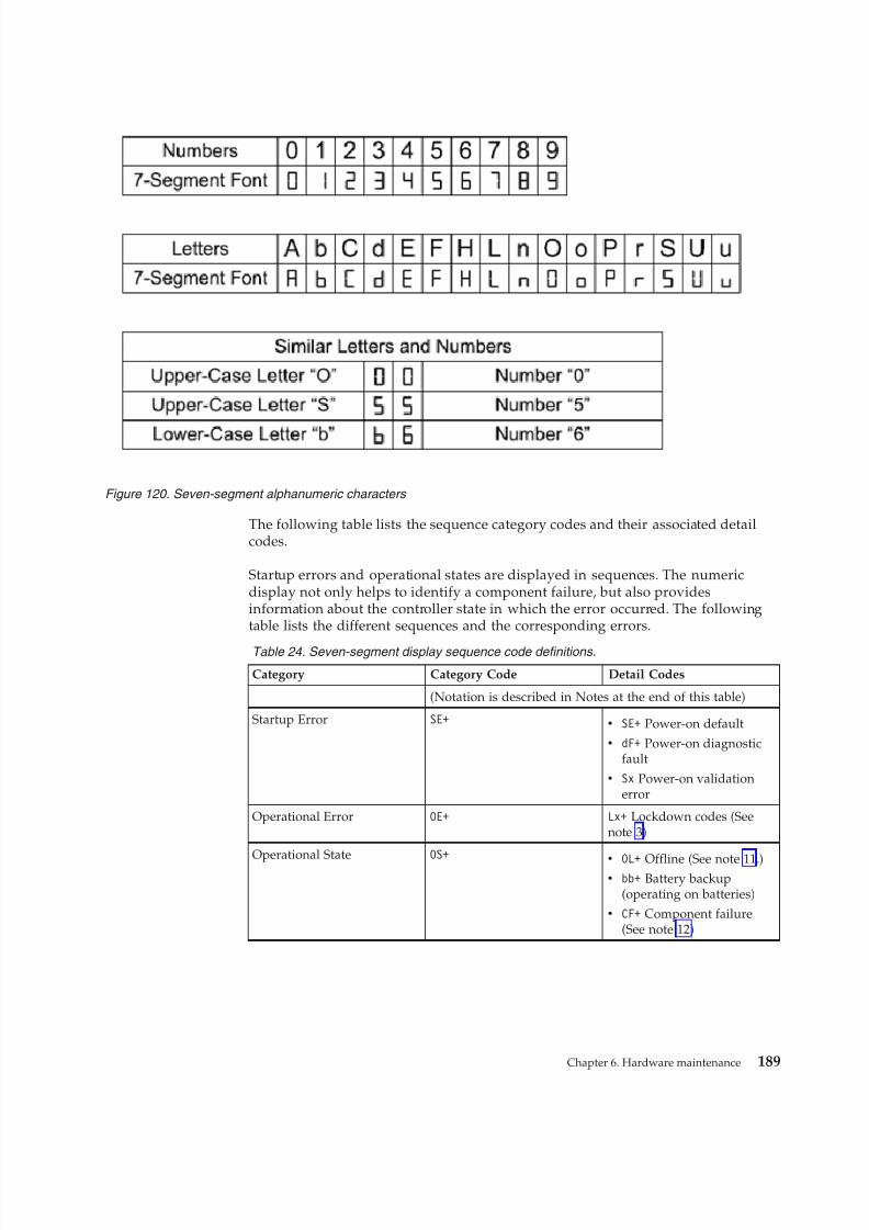
8/9/2019 Installation, User's, And Maintenance
http://slidepdf.com/reader/full/installation-users-and-maintenance 207/262
The following table lists the sequence category codes and their associated detailcodes.
Startup errors and operational states are displayed in sequences. The numericdisplay not only helps to identify a component failure, but also providesinformation about the controller state in which the error occurred. The followingtable lists the different sequences and the corresponding errors.
Table 24. Seven-segment display sequence code definitions .
Category Category Code Detail Codes
(Notation is described in Notes at the end of this table)
Startup Error SE+v SE+ Power-on default
v dF+ Power-on diagnosticfault
v Sx Power-on validationerror
Operational Error OE+ Lx+ Lockdown codes (Seenote 3)
Operational State OS+
v
OL+ Offline (See note 11.)v bb+ Battery backup
(operating on batteries)
v CF+ Component failure(See note 12)
Figure 120. Seven-segment alphanumeric characters
Chapter 6. Hardware maintenance 189

8/9/2019 Installation, User's, And Maintenance
http://slidepdf.com/reader/full/installation-users-and-maintenance 208/262
Table 24. Seven-segment display sequence code definitions (continued) .
Category Category Code Detail Codes
Component Failure CF+v dx+ Processor/Cache
DIMM (x = location. Seenote 6.)
v Cx+ Cache DIMM (x =
location. See note 7.)v Px+ Processor DIMM (x =
location. See note 8.)
v Hx+ Host card (x =location)
v Fx+ Flash drive (x =location)
v b1+ Base controller card
Diagnostic Failure dE+ Lx+ Lockdown code (Seenote 3)
Category Delimiter dash+ Separator betweencategory-detail code pairs
(See notes 4 and 9)End-Of-Sequence Delimiter blank- End-of-sequence indicator
(See notes 5 and 10)
Notes:
1. xy+ Indicates that the diagnostic LED is lit.
2. xy- Indicates that the diagnostic LED is turned off.
3. Lx+ Lockdown codes (See Table 26 on page 192)
4. dash+ All segments are off except the middle segments and the diagnostic light is on.5. blank- All segments are off and the diagnostic light is off.6. dx+ Used when there is a single memory system for processor and data cache.
7. Cx+ Used when there are separate processor and data cache memory systems.
8. Px+ Used when there are separate processor and data cache memory systems.9. Category-Detail separator is used when there is more than one category-detail pair in
the sequence. For examples, see Table 25
10. End-of-sequence indicator is automatically inserted by hardware at the end of thesequence. Example: SE+ 88+ blank- (repeat)
11. If an enclosure ID is being displayed, this sequence is programmed to display. Thecontroller is then held in reset.
12. The enclosure ID is nominally displayed during normal operation. This operationalstate is displayed if an internal controller component failure occurs while thecontroller is online. An additional detail code identifies the failed component asdefined for the Component Failure category. This sequence will continue to displayeven if the controller is later placed offline (held in reset) to service the failedcomponent.
Table 25. Repeating sequences on the seven-segment display and corresponding errors
Repeating Sequence Startup and Operational Error
Controller power-on failure:
SE+ 88+ blank-v Initial phase of normal power-on
controller insertion
v Insertion of a controller while held inreset
190 IBM System Storage DCS3700 Storage Subsystem: Installation, User's, and Maintenance Guide
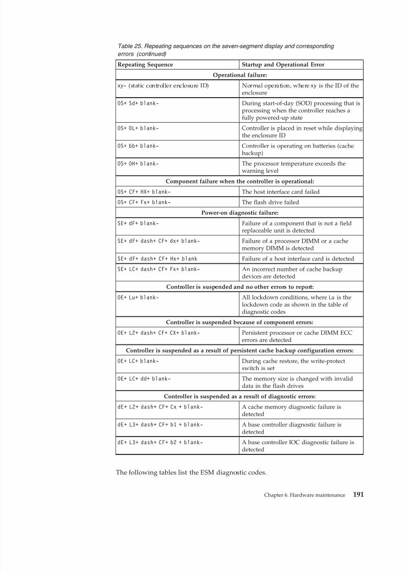
8/9/2019 Installation, User's, And Maintenance
http://slidepdf.com/reader/full/installation-users-and-maintenance 209/262
Table 25. Repeating sequences on the seven-segment display and corresponding
errors (continued)
Repeating Sequence Startup and Operational Error
Operational failure:
xy- (static controller enclosure ID) Normal operation, where xy is the ID of theenclosure
OS+ Sd+ blank- During start-of-day (SOD) processing that isprocessing when the controller reaches afully powered-up state
OS+ OL+ blank- Controller is placed in reset while displayingthe enclosure ID
OS+ bb+ blank- Controller is operating on batteries (cache backup)
OS+ OH+ blank- The processor temperature exceeds thewarning level
Component failure when the controller is operational:
OS+ CF+ HX+ blank- The host interface card failed
OS+ CF+ Fx+ blank- The flash drive failedPower-on diagnostic failure:
SE+ dF+ blank- Failure of a component that is not a fieldreplaceable unit is detected
SE+ dF+ dash+ CF+ dx+ blank- Failure of a processor DIMM or a cachememory DIMM is detected
SE+ dF+ dash+ CF+ Hx+ blank Failure of a host interface card is detected
SE+ LC+ dash+ CF+ Fx+ blank- An incorrect number of cache backupdevices are detected
Controller is suspended and no other errors to report:
OE+ Lu+ blank- All lockdown conditions, where Lu is thelockdown code as shown in the table of diagnostic codes
Controller is suspended because of component errors:
OE+ L2+ dash+ CF+ CX+ blank- Persistent processor or cache DIMM ECCerrors are detected
Controller is suspended as a result of persistent cache backup configuration errors:
OE+ LC+ blank- During cache restore, the write-protectswitch is set
OE+ LC+ dd+ blank- The memory size is changed with invaliddata in the flash drives
Controller is suspended as a result of diagnostic errors:
dE+ L2+ dash+ CF+ Cx + blank- A cache memory diagnostic failure isdetected
dE+ L3+ dash+ CF+ b1 + blank- A base controller diagnostic failure isdetected
dE+ L3+ dash+ CF+ b2 + blank- A base controller IOC diagnostic failure isdetected
The following tables list the ESM diagnostic codes.
Chapter 6. Hardware maintenance 191
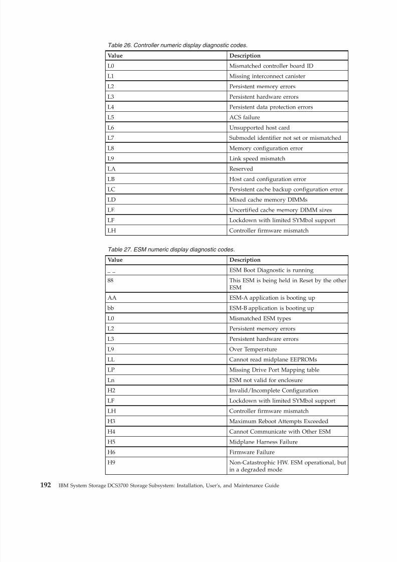
8/9/2019 Installation, User's, And Maintenance
http://slidepdf.com/reader/full/installation-users-and-maintenance 210/262
Table 26. Controller numeric display diagnostic codes .
Value Description
L0 Mismatched controller board ID
L1 Missing interconnect canister
L2 Persistent memory errors
L3 Persistent hardware errorsL4 Persistent data protection errors
L5 ACS failure
L6 Unsupported host card
L7 Submodel identifier not set or mismatched
L8 Memory configuration error
L9 Link speed mismatch
LA Reserved
LB Host card configuration error
LC Persistent cache backup configuration error
LD Mixed cache memory DIMMs
LE Uncertified cache memory DIMM sizes
LF Lockdown with limited SYMbol support
LH Controller firmware mismatch
Table 27. ESM numeric display diagnostic codes .
Value Description
_ _ ESM Boot Diagnostic is running
88 This ESM is being held in Reset by the otherESM
AA ESM-A application is booting up
bb ESM-B application is booting up
L0 Mismatched ESM types
L2 Persistent memory errors
L3 Persistent hardware errors
L9 Over Temperature
LL Cannot read midplane EEPROMs
LP Missing Drive Port Mapping table
Ln ESM not valid for enclosure
H2 Invalid/Incomplete Configuration
LF Lockdown with limited SYMbol support
LH Controller firmware mismatch
H3 Maximum Reboot Attempts Exceeded
H4 Cannot Communicate with Other ESM
H5 Midplane Harness Failure
H6 Firmware Failure
H9 Non-Catastrophic HW. ESM operational, butin a degraded mode
192 IBM System Storage DCS3700 Storage Subsystem: Installation, User's, and Maintenance Guide
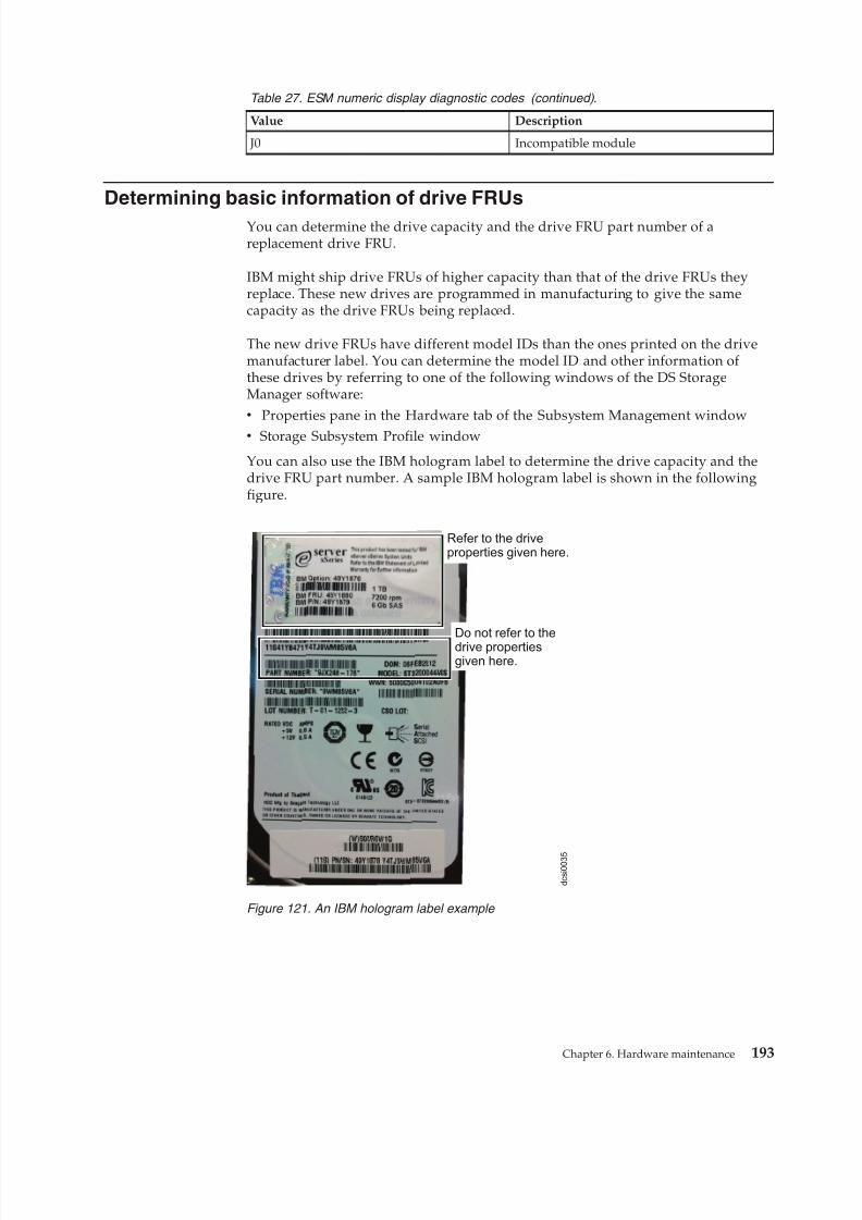
8/9/2019 Installation, User's, And Maintenance
http://slidepdf.com/reader/full/installation-users-and-maintenance 211/262
Table 27. ESM numeric display diagnostic codes (continued) .
Value Description
J0 Incompatible module
Determining basic information of drive FRUs
You can determine the drive capacity and the drive FRU part number of areplacement drive FRU.
IBM might ship drive FRUs of higher capacity than that of the drive FRUs theyreplace. These new drives are programmed in manufacturing to give the samecapacity as the drive FRUs being replaced.
The new drive FRUs have different model IDs than the ones printed on the drivemanufacturer label. You can determine the model ID and other information of these drives by referring to one of the following windows of the DS StorageManager software:v Properties pane in the Hardware tab of the Subsystem Management windowv Storage Subsystem Profile window
You can also use the IBM hologram label to determine the drive capacity and thedrive FRU part number. A sample IBM hologram label is shown in the followingfigure.
Do not refer to thedrive propertiesgiven here.
Refer to the driveproperties given here.
d c s i 0 0 3 5
Figure 121. An IBM hologram label example
Chapter 6. Hardware maintenance 193

8/9/2019 Installation, User's, And Maintenance
http://slidepdf.com/reader/full/installation-users-and-maintenance 212/262
194 IBM System Storage DCS3700 Storage Subsystem: Installation, User's, and Maintenance Guide
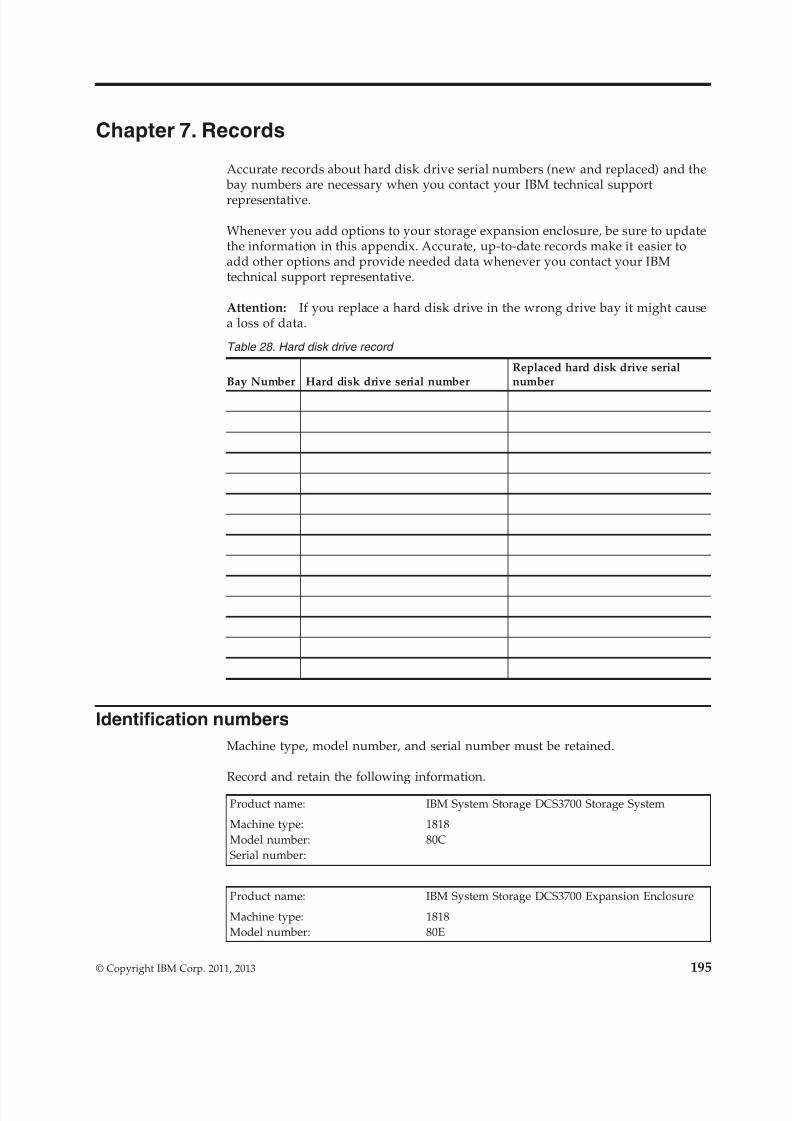
8/9/2019 Installation, User's, And Maintenance
http://slidepdf.com/reader/full/installation-users-and-maintenance 213/262
Chapter 7. Records
Accurate records about hard disk drive serial numbers (new and replaced) and the bay numbers are necessary when you contact your IBM technical support
representative.
Whenever you add options to your storage expansion enclosure, be sure to updatethe information in this appendix. Accurate, up-to-date records make it easier toadd other options and provide needed data whenever you contact your IBMtechnical support representative.
Attention: If you replace a hard disk drive in the wrong drive bay it might causea loss of data.
Table 28. Hard disk drive record
Bay Number Hard disk drive serial numberReplaced hard disk drive serialnumber
Identification numbers
Machine type, model number, and serial number must be retained.
Record and retain the following information.
Product name: IBM System Storage DCS3700 Storage System
Machine type: 1818Model number: 80CSerial number:
Product name: IBM System Storage DCS3700 Expansion Enclosure
Machine type: 1818Model number: 80E
© Copyright IBM Corp. 2011, 2013 195
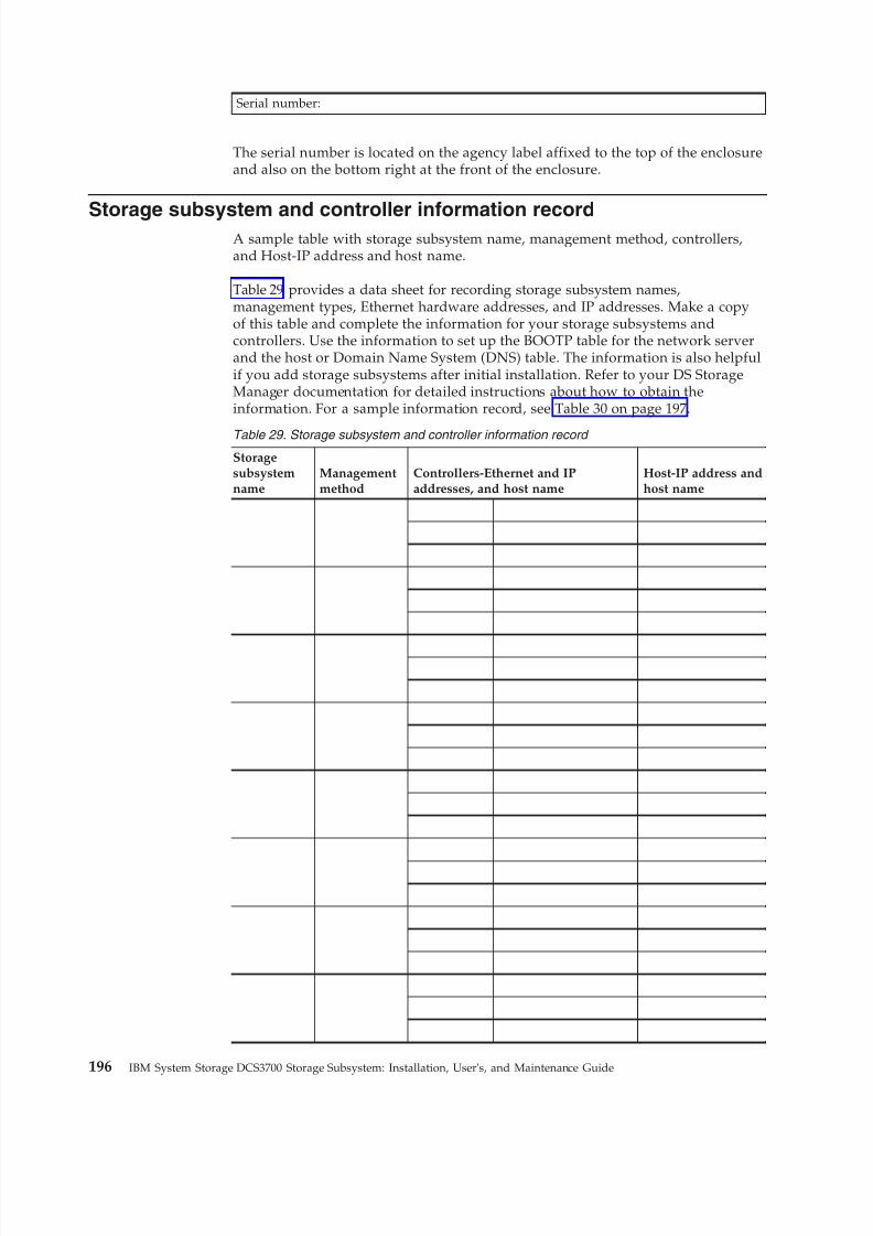
8/9/2019 Installation, User's, And Maintenance
http://slidepdf.com/reader/full/installation-users-and-maintenance 214/262
Serial number:
The serial number is located on the agency label affixed to the top of the enclosureand also on the bottom right at the front of the enclosure.
Storage subsystem and controller information recordA sample table with storage subsystem name, management method, controllers,and Host-IP address and host name.
Table 29 provides a data sheet for recording storage subsystem names,management types, Ethernet hardware addresses, and IP addresses. Make a copyof this table and complete the information for your storage subsystems andcontrollers. Use the information to set up the BOOTP table for the network serverand the host or Domain Name System (DNS) table. The information is also helpfulif you add storage subsystems after initial installation. Refer to your DS StorageManager documentation for detailed instructions about how to obtain theinformation. For a sample information record, see Table 30 on page 197.
Table 29. Storage subsystem and controller information record
Storagesubsystemname
Managementmethod
Controllers-Ethernet and IPaddresses, and host name
Host-IP address andhost name
196 IBM System Storage DCS3700 Storage Subsystem: Installation, User's, and Maintenance Guide
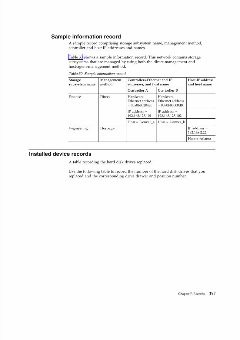
8/9/2019 Installation, User's, And Maintenance
http://slidepdf.com/reader/full/installation-users-and-maintenance 215/262
Sample information recordA sample record comprising storage subsystem name, management method,controller and host IP addresses and names.
Table 30 shows a sample information record. This network contains storagesubsystems that are managed by using both the direct-management andhost-agent-management method.
Table 30. Sample information record
Storagesubsystem name
Managementmethod
Controllers-Ethernet and IPaddresses, and host name
Host-IP addressand host name
Controller A Controller B
Finance Direct HardwareEthernet address= 00a0b8020420
HardwareEthernet address= 00a0b80000d8
IP address =192.168.128.101
IP address =192.168.128.102
Host = Denver_a Host = Denver_b
Engineering Host-agent IP address =192.168.2.22
Host = Atlanta
Installed device records
A table recording the hard disk drives replaced.
Use the following table to record the number of the hard disk drives that youreplaced and the corresponding drive drawer and position number.
Chapter 7. Records 197

8/9/2019 Installation, User's, And Maintenance
http://slidepdf.com/reader/full/installation-users-and-maintenance 216/262
198 IBM System Storage DCS3700 Storage Subsystem: Installation, User's, and Maintenance Guide
8/9/2019 Installation, User's, And Maintenance
http://slidepdf.com/reader/full/installation-users-and-maintenance 217/262
Chapter 8. Rack mounting template
Duplicate copies of the rack mounting templates to tear out and use.
This appendix provides duplicate copies of the rack mounting templates. If youwant to tear out the templates from this document for easier use, use these copiesrather than those provided in “Installing the support rails” on page 35.
Use the following templates (Figure 122 on page 200 and Figure 123 on page 201)to identify the proper locations for inserting M5 screws when mounting thesupport rails and DCS3700 to a rack. The locations for the M5 screws arehighlighted in the templates.
The DCS3700 is 4 U high. Align the template with the rack at a U boundary. U boundaries are shown as horizontal dashed lines in the rack mounting templates.
Note: The mounting holes that are shown in the following templates are square.The holes in your rack might be round or square.
© Copyright IBM Corp. 2011, 2013 199
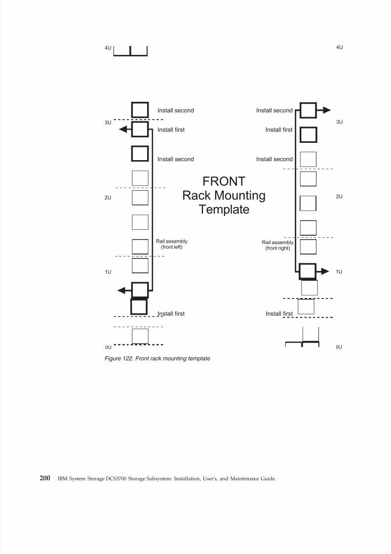
8/9/2019 Installation, User's, And Maintenance
http://slidepdf.com/reader/full/installation-users-and-maintenance 218/262
3U3U
2U 2U
1U 1U
0U 0U
Rail assembly(front left)
Rail assembly(front right)
FRONT
Rack MountingTemplate
4U4U
Install second
Install first
Install second
Install first
Install first Install first
Install second Install second
Figure 122. Front rack mounting template
200 IBM System Storage DCS3700 Storage Subsystem: Installation, User's, and Maintenance Guide
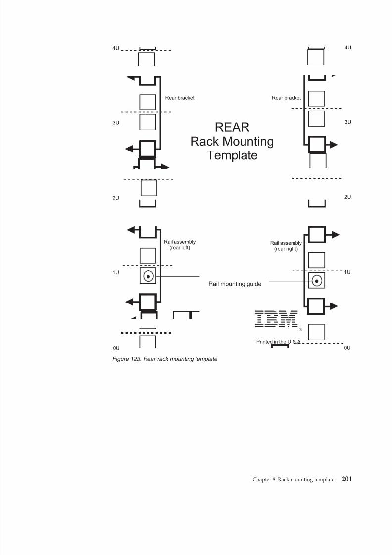
8/9/2019 Installation, User's, And Maintenance
http://slidepdf.com/reader/full/installation-users-and-maintenance 219/262
®
3U3U
2U 2U
1U 1U
0U 0U
Rail assembly(rear left)
Rail assembly(rear right)
Printed in the U.S.A
REARRack Mounting
Template
Rail mounting guide
4U4U
Rear bracket Rear bracket
Figure 123. Rear rack mounting template
Chapter 8. Rack mounting template 201

8/9/2019 Installation, User's, And Maintenance
http://slidepdf.com/reader/full/installation-users-and-maintenance 220/262
202 IBM System Storage DCS3700 Storage Subsystem: Installation, User's, and Maintenance Guide
8/9/2019 Installation, User's, And Maintenance
http://slidepdf.com/reader/full/installation-users-and-maintenance 221/262
Chapter 9. Specifications for non-IBM rack installation
Safety requirements and rack specifications to install the storage subsystem into anon-IBM rack.
The following instructions provide safety requirements and rack specifications forinstalling the DCS3700 storage system and DCS3700 storage expansion enclosuresinto non-IBM racks.
Note: The information in this section applies to 19–inch racks. It is yourresponsibility, working with your rack manufacturer, to ensure that the non-IBMrack chosen meets the safety requirements and specifications listed in this section.
General safety requirements for IBM products installed in a non-IBM
rack or cabinet
Safety requirements to follow for a non-IBM rack or cabinet.
The general safety requirements for IBM products installed in non-IBM racks are:1. Any product or component that plugs into either an IBM power distribution
unit or mains power (via a power cord), or uses any voltage over 42 V ac or60 V dc (considered to be hazardous voltage) must be Safety Certified by aNationally Recognized Test Laboratory (NRTL) for the country in which it will
be installed.Some of the items that require safety certification may include: the rack orcabinet (if it contains electrical components integral to the rack or cabinet), fantrays, power distribution unit, uninterruptible power supplies, multi-outletstrips, or any other products installed in the rack or cabinet that connect to
hazardous voltage.Examples of OSHA-approved NRTLs for the U.S.:v ULv ETLv CSA (with CSA NRTL or CSA US mark)Examples of approved NRTLs for Canada:
a. UL (Ulc mark)b. ETL (ETLc mark)
c. CSAThe European Union requires a CE mark and a Manufacturer's Declaration of Conformity (DOC).
Certified products should have the NRTL logos or marks somewhere on theproduct or product label. However, proof of certification must be madeavailable to IBM upon request. Proof consists of such items as copies of theNRTL license or certificate, a CB Certificate, a Letter of Authorization to applythe NRTL mark, the first few pages of the NRTL certification report, Listing inan NRTL publication, or a copy of the UL Yellow Card. Proof should containthe manufacturer's name, product type and model, standard to which it wascertified, the NRTL name or logo, the NRTL file number or license number,and a list of any Conditions of Acceptance or Deviations. A Manufacturer'sDeclaration is not proof of certification by an NRTL.
© Copyright IBM Corp. 2011, 2013 203
8/9/2019 Installation, User's, And Maintenance
http://slidepdf.com/reader/full/installation-users-and-maintenance 222/262
2. The rack or cabinet must meet all electrical and mechanical safety legalrequirements for the country in which it is installed.The rack or cabinet must be free of exposed hazards (such as voltages over 60V dc or 42 V ac, energy over 240 VA, sharp edges, mechanical pinch points, orhot surfaces).
3. There must be an accessible and unambiguous disconnect device for each
product in the rack, including any power distribution unit.A disconnect device may consist of either the plug on the power cord (if thepower cord is no longer than 1.8 m (6 ft.)), the appliance inlet receptacle (if the power cord is of a detachable type), or a power on/off switch, or anEmergency Power Off switch on the rack, provided all power is removed fromthe rack or product by the disconnect device.If the rack/or cabinet has electrical components (such as fan trays or lights),the rack must have an accessible and unambiguous disconnect device.
4. The rack or cabinet, power distribution unit and multi-outlet strips, andproducts installed in the rack or cabinet must all be properly grounded to thecustomer facility ground.There must be no more than 0.1 Ohms between the ground pin of the power
distribution unit or rack plug and any touchable metal or conductive surfaceon the rack and on the products installed in the rack. Grounding method mustcomply with applicable country's electric code (such as NEC or CEC). Groundcontinuity can be verified by your IBM service personnel, after the installationis completed, and should be verified prior to the first service activity.
5. The voltage rating of the power distribution unit and multi-outlet strips must be compatible with the products plugged into them.The power distribution unit or multi-outlet strips current and power ratingsare rated at 80 percent of the building supply circuit (as required by theNational Electrical Code and the Canadian Electrical Code). The total loadconnected to the power distribution unit must be less than the rating of thepower distribution unit. For example, a power distribution unit with a 30 A
connection will be rated for a total load of 24 A (30 A x 80 percent). Therefore,the sum of all equipment connected to the power distribution unit in thisexample must be lower than the 24 A rating.If an uninterruptible power supply is installed, it must meet all the aboveelectrical safety requirements as described for a power distribution unit(including certification by an NRTL).
6. The rack or cabinet, power distribution unit, uninterruptible power supply,multi-outlet strips and all products in the rack or cabinet must be installedaccording to the manufacturer's instructions, and in accordance with allnational, state or province, and local codes and laws.The rack or cabinet, power distribution unit, uninterruptible power supply,multi-outlet strips and all products in the rack or cabinet must be used as
intended by the manufacturer (per manufacturer's product documentation andmarketing literature).7. All documentation for use and installation of the rack or cabinet, power
distribution unit, uninterruptible power supply, and all products in the rack orcabinet, including safety information, must be available on-site.
8. If there is more than one source of power in the rack cabinet, there must beclearly visible safety labels for "Multiple Power Source" (in the languagesrequired for the country in which the product is installed).
204 IBM System Storage DCS3700 Storage Subsystem: Installation, User's, and Maintenance Guide
8/9/2019 Installation, User's, And Maintenance
http://slidepdf.com/reader/full/installation-users-and-maintenance 223/262
9. If the rack or cabinet or any products installed in the cabinet had safety orweight labels applied by the manufacturer, they must be intact and translatedinto the languages required for the country in which the product is installed.
10. The rack or cabinet configuration must comply with all IBM requirements for"safe to service" (contact your IBM Installation Planning Representative forassistance in determining if the environment is safe).
There must be no unique maintenance procedures or tools required forservice.11. Elevated service installations, where the product(s) to be serviced are installed
between 1.5 m and 3.7 m (5 ft. and 12 ft.) above the floor, require theavailability of an OSHA- and CSA-approved nonconductive step ladder. If aladder is required for service, the customer must supply the OSHA- and CSA-approved nonconductive step ladder (unless other arrangements have beenmade with the local IBM Service Branch Office). Products installed over 2.9 m(9 ft.) above the floor requires a Special Bid to be completed before they can
be serviced by IBM service personnel.For products not intended for rack-mounting to be serviced by IBM, theproducts and parts that will be replaced as part of that service must not weighover 11.4 kg (25 lb). (Contact your Installation Planning Representative if indoubt).
12. There must not be any special education or training required for safe servicingof any of the product(s) installed in the racks. (Contact your InstallationPlanning Representative if in doubt).
Rack specifications
Specifications to follow for a non-IBM rack.
When installing a DCS3700 storage system or DCS3700 storage expansionenclosure into a non-IBM rack, follow the specifications below.
1. The rack or cabinet must meet the EIA Standard EIA-310-D for 19-inch racks
published August 24, 1992. The EIA-310-D standard specifies internaldimensions, for example, the width of the rack opening (width of the chassis),the width of the module mounting flanges, the mounting hole spacing, and thedepth of the mounting flanges. The EIA-310-D standard does not control theoverall external width of the rack. There are no restrictions on the location of side walls and corner posts relative to the internal mounting space.The front rack opening must be 451 mm wide + 0.75 mm (17.75 in. + 0.03 in.),and the rail-mounting holes must be 465 mm + 0.8 mm (18.3 in. + 0.03 in.)apart on center (horizontal width between vertical columns of holes on the twofront-mounting flanges and on the two rear-mounting flanges).
Chapter 9. Specifications for non-IBM rack installation 205
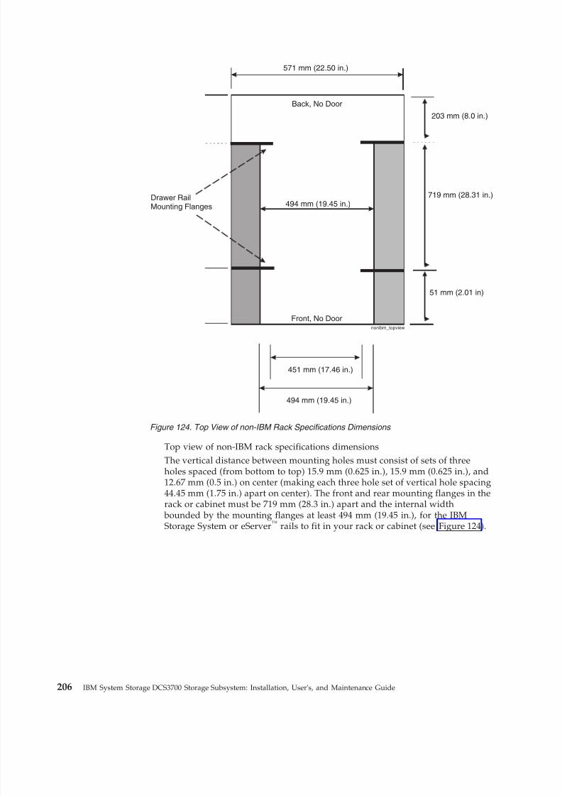
8/9/2019 Installation, User's, And Maintenance
http://slidepdf.com/reader/full/installation-users-and-maintenance 224/262
Top view of non-IBM rack specifications dimensionsThe vertical distance between mounting holes must consist of sets of threeholes spaced (from bottom to top) 15.9 mm (0.625 in.), 15.9 mm (0.625 in.), and12.67 mm (0.5 in.) on center (making each three hole set of vertical hole spacing44.45 mm (1.75 in.) apart on center). The front and rear mounting flanges in therack or cabinet must be 719 mm (28.3 in.) apart and the internal width
bounded by the mounting flanges at least 494 mm (19.45 in.), for the IBMStorage System or eServer™ rails to fit in your rack or cabinet (see Figure 124).
nonibm_topview
Back, No Door
571 mm (22.50 in.)
Drawer RailMounting Flanges 494 mm (19.45 in.)
Front, No Door
451 mm (17.46 in.)
494 mm (19.45 in.)
203 mm (8.0 in.)
719 mm (28.31 in.)
51 mm (2.01 in)
Figure 124. Top View of non-IBM Rack Specifications Dimensions
206 IBM System Storage DCS3700 Storage Subsystem: Installation, User's, and Maintenance Guide
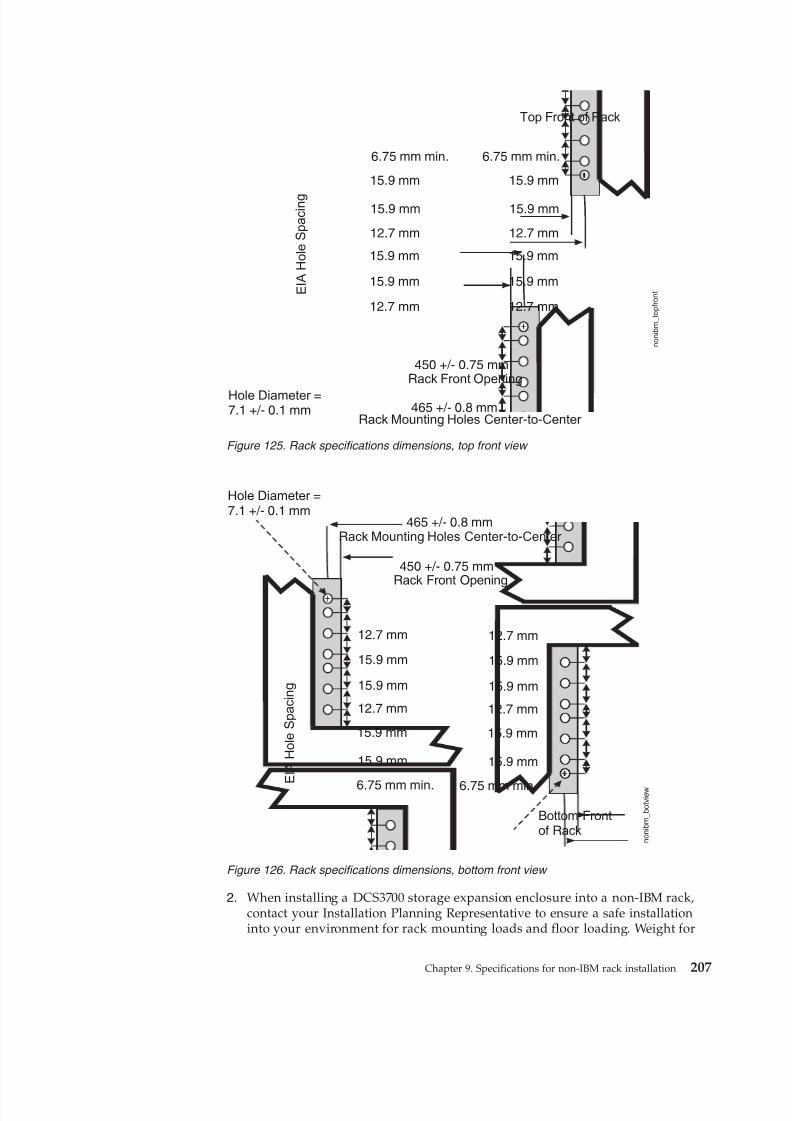
8/9/2019 Installation, User's, And Maintenance
http://slidepdf.com/reader/full/installation-users-and-maintenance 225/262
2. When installing a DCS3700 storage expansion enclosure into a non-IBM rack,contact your Installation Planning Representative to ensure a safe installationinto your environment for rack mounting loads and floor loading. Weight for
Top Front of Rack
E I A
H o l e S p a c i n g
6.75 mm min.
15.9 mm
15.9 mm
15.9 mm
15.9 mm
12.7 mm
12.7 mm
Hole Diameter =7.1 +/- 0.1 mm
450 +/- 0.75 mmRack Front Opening
465 +/- 0.8 mmRack Mounting Holes Center-to-Center
6.75 mm min.
15.9 mm
15.9 mm
12.7 mm
15.9 mm
15.9 mm
12.7 mm
n o n i b m_
t o p f r o n t
Figure 125. Rack specifications dimensions, top front view
Bottom Frontof Rack
E I A
H o l e S p a c i n g
6.75 mm min.
15.9 mm
15.9 mm
15.9 mm
15.9 mm
12.7 mm
12.7 mm
Hole Diameter =7.1 +/- 0.1 mm
450 +/- 0.75 mmRack Front Opening
465 +/- 0.8 mmRack Mounting Holes Center-to-Center
6.75 mm min.
15.9 mm
15.9 mm
12.7 mm
15.9 mm
15.9 mm
12.7 mm
n o n
i b m
_ b
o t v i e
w
Figure 126. Rack specifications dimensions, bottom front view
Chapter 9. Specifications for non-IBM rack installation 207
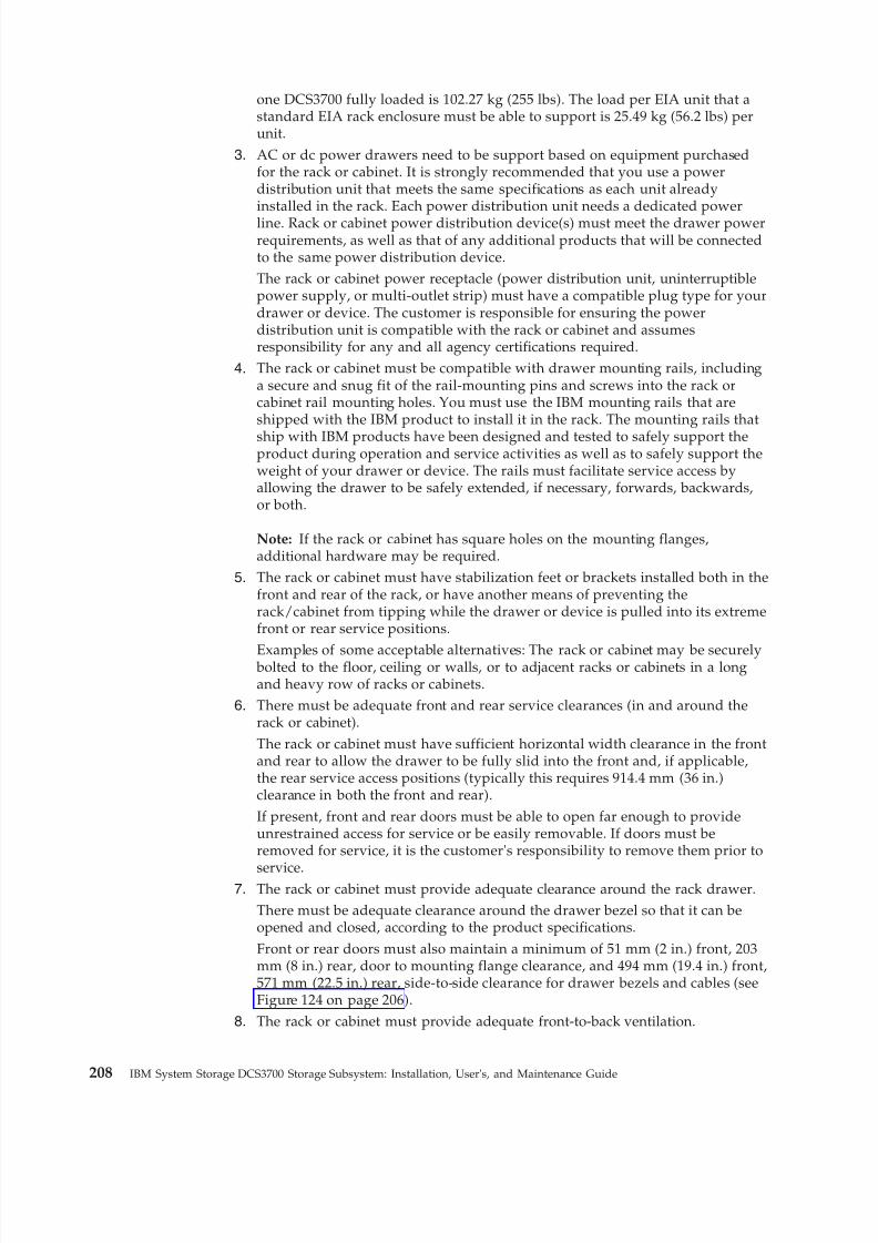
8/9/2019 Installation, User's, And Maintenance
http://slidepdf.com/reader/full/installation-users-and-maintenance 226/262
one DCS3700 fully loaded is 102.27 kg (255 lbs). The load per EIA unit that astandard EIA rack enclosure must be able to support is 25.49 kg (56.2 lbs) perunit.
3. AC or dc power drawers need to be support based on equipment purchasedfor the rack or cabinet. It is strongly recommended that you use a powerdistribution unit that meets the same specifications as each unit alreadyinstalled in the rack. Each power distribution unit needs a dedicated powerline. Rack or cabinet power distribution device(s) must meet the drawer powerrequirements, as well as that of any additional products that will be connectedto the same power distribution device.The rack or cabinet power receptacle (power distribution unit, uninterruptiblepower supply, or multi-outlet strip) must have a compatible plug type for yourdrawer or device. The customer is responsible for ensuring the powerdistribution unit is compatible with the rack or cabinet and assumesresponsibility for any and all agency certifications required.
4. The rack or cabinet must be compatible with drawer mounting rails, includinga secure and snug fit of the rail-mounting pins and screws into the rack orcabinet rail mounting holes. You must use the IBM mounting rails that areshipped with the IBM product to install it in the rack. The mounting rails that
ship with IBM products have been designed and tested to safely support theproduct during operation and service activities as well as to safely support theweight of your drawer or device. The rails must facilitate service access byallowing the drawer to be safely extended, if necessary, forwards, backwards,or both.
Note: If the rack or cabinet has square holes on the mounting flanges,additional hardware may be required.
5. The rack or cabinet must have stabilization feet or brackets installed both in thefront and rear of the rack, or have another means of preventing therack/cabinet from tipping while the drawer or device is pulled into its extremefront or rear service positions.
Examples of some acceptable alternatives: The rack or cabinet may be securely bolted to the floor, ceiling or walls, or to adjacent racks or cabinets in a longand heavy row of racks or cabinets.
6. There must be adequate front and rear service clearances (in and around therack or cabinet).The rack or cabinet must have sufficient horizontal width clearance in the frontand rear to allow the drawer to be fully slid into the front and, if applicable,the rear service access positions (typically this requires 914.4 mm (36 in.)clearance in both the front and rear).If present, front and rear doors must be able to open far enough to provideunrestrained access for service or be easily removable. If doors must beremoved for service, it is the customer's responsibility to remove them prior to
service.7. The rack or cabinet must provide adequate clearance around the rack drawer.
There must be adequate clearance around the drawer bezel so that it can beopened and closed, according to the product specifications.Front or rear doors must also maintain a minimum of 51 mm (2 in.) front, 203mm (8 in.) rear, door to mounting flange clearance, and 494 mm (19.4 in.) front,571 mm (22.5 in.) rear, side-to-side clearance for drawer bezels and cables (seeFigure 124 on page 206).
8. The rack or cabinet must provide adequate front-to-back ventilation.
208 IBM System Storage DCS3700 Storage Subsystem: Installation, User's, and Maintenance Guide

8/9/2019 Installation, User's, And Maintenance
http://slidepdf.com/reader/full/installation-users-and-maintenance 227/262
For optimum ventilation, it is recommended the rack or cabinet not have afront door. If the rack or cabinet has doors, the doors must be fully perforatedso that there is proper front-to-back airflow to maintain the required drawerambient inlet temperature as specified in the server specifications. Theperforations should yield at least 34 percent minimum open area per squareinch.
Chapter 9. Specifications for non-IBM rack installation 209

8/9/2019 Installation, User's, And Maintenance
http://slidepdf.com/reader/full/installation-users-and-maintenance 228/262
210 IBM System Storage DCS3700 Storage Subsystem: Installation, User's, and Maintenance Guide
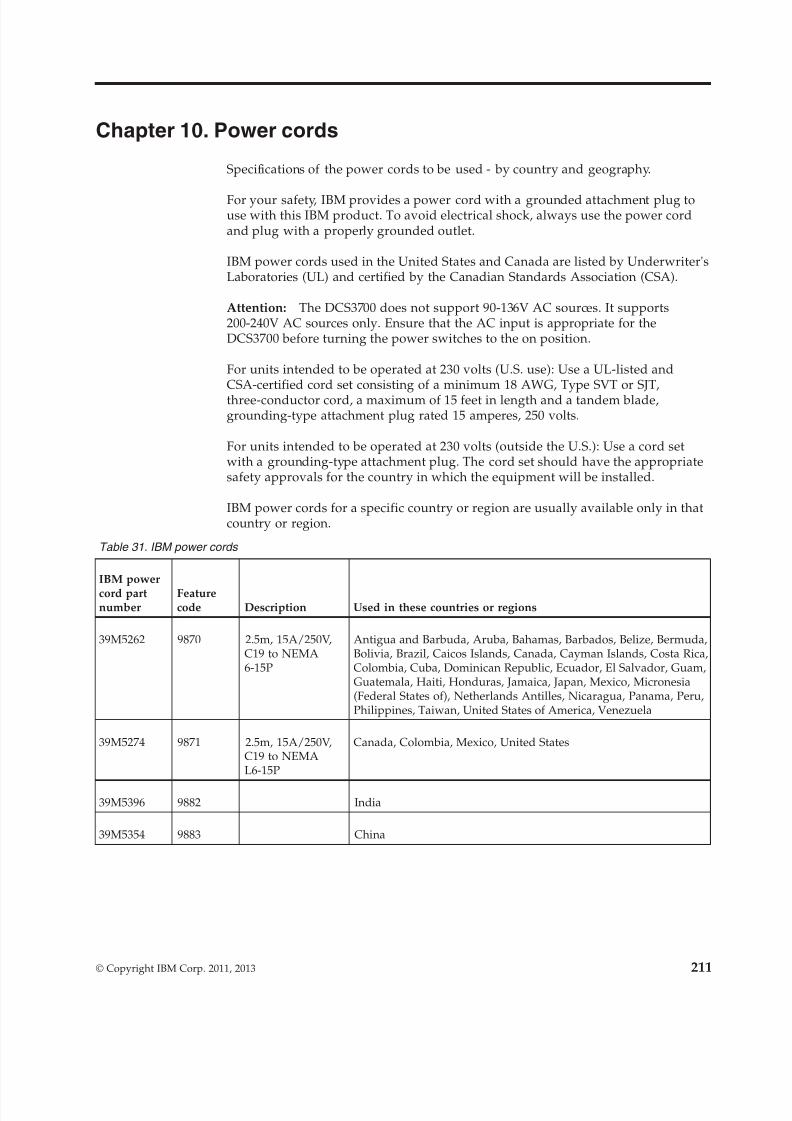
8/9/2019 Installation, User's, And Maintenance
http://slidepdf.com/reader/full/installation-users-and-maintenance 229/262
Chapter 10. Power cords
Specifications of the power cords to be used - by country and geography.
For your safety, IBM provides a power cord with a grounded attachment plug touse with this IBM product. To avoid electrical shock, always use the power cordand plug with a properly grounded outlet.
IBM power cords used in the United States and Canada are listed by Underwriter'sLaboratories (UL) and certified by the Canadian Standards Association (CSA).
Attention: The DCS3700 does not support 90-136V AC sources. It supports200-240V AC sources only. Ensure that the AC input is appropriate for theDCS3700 before turning the power switches to the on position.
For units intended to be operated at 230 volts (U.S. use): Use a UL-listed andCSA-certified cord set consisting of a minimum 18 AWG, Type SVT or SJT,three-conductor cord, a maximum of 15 feet in length and a tandem blade,grounding-type attachment plug rated 15 amperes, 250 volts.
For units intended to be operated at 230 volts (outside the U.S.): Use a cord setwith a grounding-type attachment plug. The cord set should have the appropriatesafety approvals for the country in which the equipment will be installed.
IBM power cords for a specific country or region are usually available only in thatcountry or region.
Table 31. IBM power cords
IBM power
cord partnumber
Featurecode Description Used in these countries or regions
39M5262 9870 2.5m, 15A/250V,C19 to NEMA6-15P
Antigua and Barbuda, Aruba, Bahamas, Barbados, Belize, Bermuda,Bolivia, Brazil, Caicos Islands, Canada, Cayman Islands, Costa Rica,Colombia, Cuba, Dominican Republic, Ecuador, El Salvador, Guam,Guatemala, Haiti, Honduras, Jamaica, Japan, Mexico, Micronesia(Federal States of), Netherlands Antilles, Nicaragua, Panama, Peru,Philippines, Taiwan, United States of America, Venezuela
39M5274 9871 2.5m, 15A/250V,C19 to NEMAL6-15P
Canada, Colombia, Mexico, United States
39M5396 9882 India
39M5354 9883 China
© Copyright IBM Corp. 2011, 2013 211
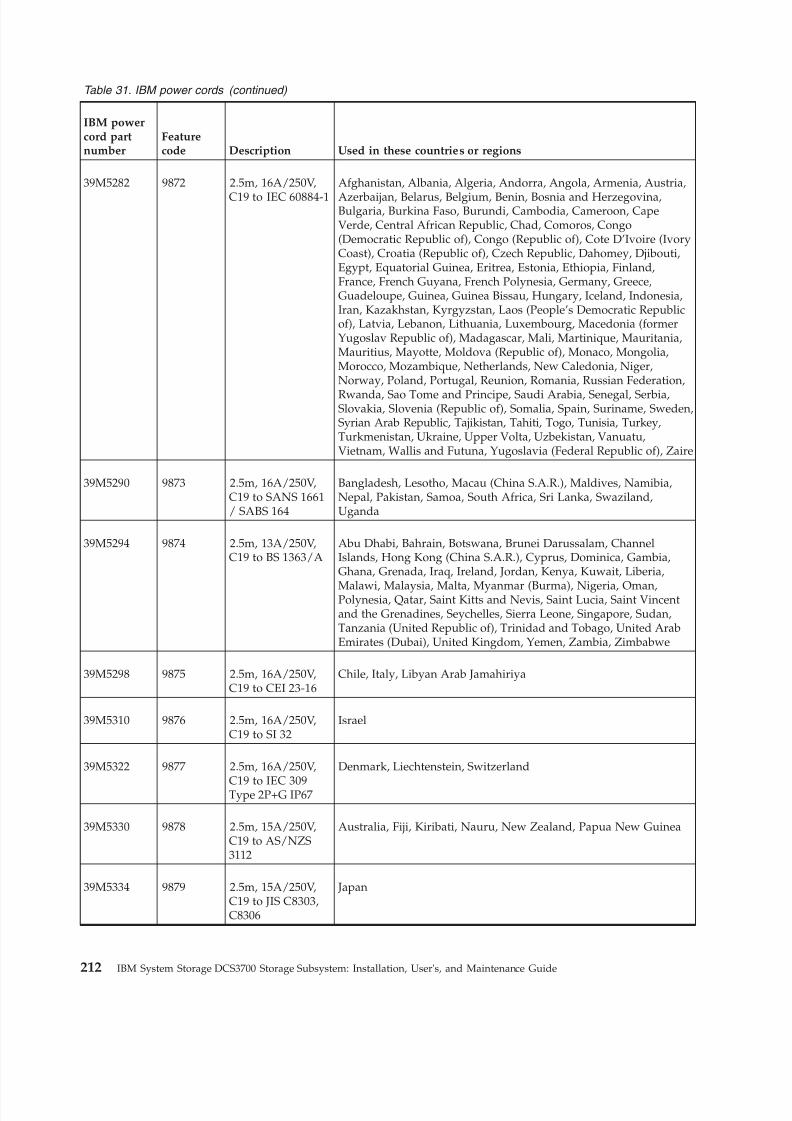
8/9/2019 Installation, User's, And Maintenance
http://slidepdf.com/reader/full/installation-users-and-maintenance 230/262
Table 31. IBM power cords (continued)
IBM powercord partnumber
Featurecode Description Used in these countries or regions
39M5282 9872 2.5m, 16A/250V,
C19 to IEC 60884-1
Afghanistan, Albania, Algeria, Andorra, Angola, Armenia, Austria,
Azerbaijan, Belarus, Belgium, Benin, Bosnia and Herzegovina,Bulgaria, Burkina Faso, Burundi, Cambodia, Cameroon, CapeVerde, Central African Republic, Chad, Comoros, Congo(Democratic Republic of), Congo (Republic of), Cote D’Ivoire (IvoryCoast), Croatia (Republic of), Czech Republic, Dahomey, Djibouti,Egypt, Equatorial Guinea, Eritrea, Estonia, Ethiopia, Finland,France, French Guyana, French Polynesia, Germany, Greece,Guadeloupe, Guinea, Guinea Bissau, Hungary, Iceland, Indonesia,Iran, Kazakhstan, Kyrgyzstan, Laos (People’s Democratic Republicof), Latvia, Lebanon, Lithuania, Luxembourg, Macedonia (formerYugoslav Republic of), Madagascar, Mali, Martinique, Mauritania,Mauritius, Mayotte, Moldova (Republic of), Monaco, Mongolia,Morocco, Mozambique, Netherlands, New Caledonia, Niger,Norway, Poland, Portugal, Reunion, Romania, Russian Federation,
Rwanda, Sao Tome and Principe, Saudi Arabia, Senegal, Serbia,Slovakia, Slovenia (Republic of), Somalia, Spain, Suriname, Sweden,Syrian Arab Republic, Tajikistan, Tahiti, Togo, Tunisia, Turkey,Turkmenistan, Ukraine, Upper Volta, Uzbekistan, Vanuatu,Vietnam, Wallis and Futuna, Yugoslavia (Federal Republic of), Zaire
39M5290 9873 2.5m, 16A/250V,C19 to SANS 1661/ SABS 164
Bangladesh, Lesotho, Macau (China S.A.R.), Maldives, Namibia,Nepal, Pakistan, Samoa, South Africa, Sri Lanka, Swaziland,Uganda
39M5294 9874 2.5m, 13A/250V,C19 to BS 1363/A
Abu Dhabi, Bahrain, Botswana, Brunei Darussalam, ChannelIslands, Hong Kong (China S.A.R.), Cyprus, Dominica, Gambia,Ghana, Grenada, Iraq, Ireland, Jordan, Kenya, Kuwait, Liberia,
Malawi, Malaysia, Malta, Myanmar (Burma), Nigeria, Oman,Polynesia, Qatar, Saint Kitts and Nevis, Saint Lucia, Saint Vincentand the Grenadines, Seychelles, Sierra Leone, Singapore, Sudan,Tanzania (United Republic of), Trinidad and Tobago, United ArabEmirates (Dubai), United Kingdom, Yemen, Zambia, Zimbabwe
39M5298 9875 2.5m, 16A/250V,C19 to CEI 23-16
Chile, Italy, Libyan Arab Jamahiriya
39M5310 9876 2.5m, 16A/250V,C19 to SI 32
Israel
39M5322 9877 2.5m, 16A/250V,
C19 to IEC 309Type 2P+G IP67
Denmark, Liechtenstein, Switzerland
39M5330 9878 2.5m, 15A/250V,C19 to AS/NZS3112
Australia, Fiji, Kiribati, Nauru, New Zealand, Papua New Guinea
39M5334 9879 2.5m, 15A/250V,C19 to JIS C8303,C8306
Japan
212 IBM System Storage DCS3700 Storage Subsystem: Installation, User's, and Maintenance Guide
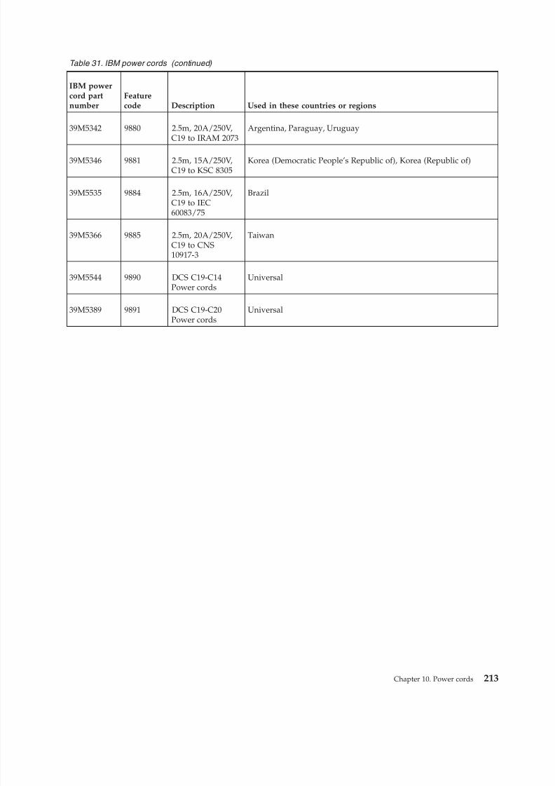
8/9/2019 Installation, User's, And Maintenance
http://slidepdf.com/reader/full/installation-users-and-maintenance 231/262
Table 31. IBM power cords (continued)
IBM powercord partnumber
Featurecode Description Used in these countries or regions
39M5342 9880 2.5m, 20A/250V,
C19 to IRAM 2073
Argentina, Paraguay, Uruguay
39M5346 9881 2.5m, 15A/250V,C19 to KSC 8305
Korea (Democratic People’s Republic of), Korea (Republic of)
39M5535 9884 2.5m, 16A/250V,C19 to IEC60083/75
Brazil
39M5366 9885 2.5m, 20A/250V,C19 to CNS10917-3
Taiwan
39M5544 9890 DCS C19-C14Power cords
Universal
39M5389 9891 DCS C19-C20Power cords
Universal
Chapter 10. Power cords 213

8/9/2019 Installation, User's, And Maintenance
http://slidepdf.com/reader/full/installation-users-and-maintenance 232/262
214 IBM System Storage DCS3700 Storage Subsystem: Installation, User's, and Maintenance Guide
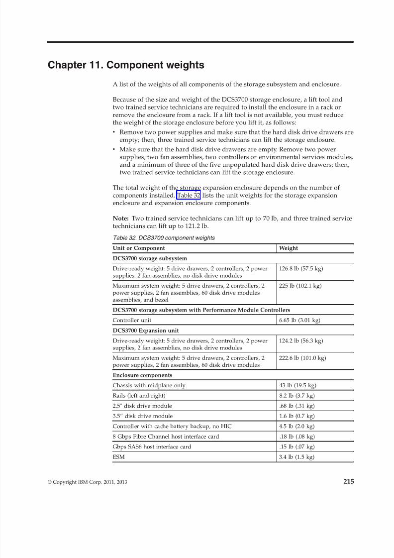
8/9/2019 Installation, User's, And Maintenance
http://slidepdf.com/reader/full/installation-users-and-maintenance 233/262
Chapter 11. Component weights
A list of the weights of all components of the storage subsystem and enclosure.
Because of the size and weight of the DCS3700 storage enclosure, a lift tool andtwo trained service technicians are required to install the enclosure in a rack orremove the enclosure from a rack. If a lift tool is not available, you must reducethe weight of the storage enclosure before you lift it, as follows:v Remove two power supplies and make sure that the hard disk drive drawers are
empty; then, three trained service technicians can lift the storage enclosure.v Make sure that the hard disk drive drawers are empty. Remove two power
supplies, two fan assemblies, two controllers or environmental services modules,and a minimum of three of the five unpopulated hard disk drive drawers; then,two trained service technicians can lift the storage enclosure.
The total weight of the storage expansion enclosure depends on the number of
components installed. Table 32 lists the unit weights for the storage expansionenclosure and expansion enclosure components.
Note: Two trained service technicians can lift up to 70 lb, and three trained servicetechnicians can lift up to 121.2 lb.
Table 32. DCS3700 component weights
Unit or Component Weight
DCS3700 storage subsystem
Drive-ready weight: 5 drive drawers, 2 controllers, 2 powersupplies, 2 fan assemblies, no disk drive modules
126.8 lb (57.5 kg)
Maximum system weight: 5 drive drawers, 2 controllers, 2
power supplies, 2 fan assemblies, 60 disk drive modulesassemblies, and bezel
225 lb (102.1 kg)
DCS3700 storage subsystem with Performance Module Controllers
Controller unit 6.65 lb (3.01 kg)
DCS3700 Expansion unit
Drive-ready weight: 5 drive drawers, 2 controllers, 2 powersupplies, 2 fan assemblies, no disk drive modules
124.2 lb (56.3 kg)
Maximum system weight: 5 drive drawers, 2 controllers, 2power supplies, 2 fan assemblies, 60 disk drive modules
222.6 lb (101.0 kg)
Enclosure components
Chassis with midplane only 43 lb (19.5 kg)
Rails (left and right) 8.2 lb (3.7 kg)
2.5" disk drive module .68 lb (.31 kg)
3.5” disk drive module 1.6 lb (0.7 kg)
Controller with cache battery backup, no HIC 4.5 lb (2.0 kg)
8 Gbps Fibre Channel host interface card .18 lb (.08 kg)
Gbps SAS6 host interface card .15 lb (.07 kg)
ESM 3.4 lb (1.5 kg)
© Copyright IBM Corp. 2011, 2013 215
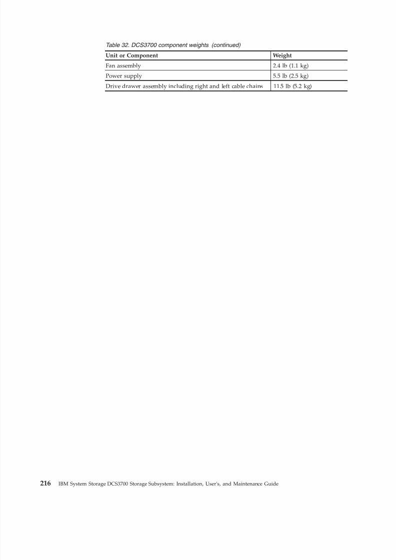
8/9/2019 Installation, User's, And Maintenance
http://slidepdf.com/reader/full/installation-users-and-maintenance 234/262
Table 32. DCS3700 component weights (continued)
Unit or Component Weight
Fan assembly 2.4 lb (1.1 kg)
Power supply 5.5 lb (2.5 kg)
Drive drawer assembly including right and left cable chains 11.5 lb (5.2 kg)
216 IBM System Storage DCS3700 Storage Subsystem: Installation, User's, and Maintenance Guide
8/9/2019 Installation, User's, And Maintenance
http://slidepdf.com/reader/full/installation-users-and-maintenance 235/262
Notices
This information was developed for products and services offered in the U.S.A.
IBM may not offer the products, services, or features discussed in this document inother countries. Consult your local IBM representative for information on theproducts and services currently available in your area. Any reference to an IBMproduct, program, or service is not intended to state or imply that only that IBMproduct, program, or service may be used. Any functionally equivalent product,program, or service that does not infringe any IBM intellectual property right may
be used instead. However, it is the user's responsibility to evaluate and verify theoperation of any non-IBM product, program, or service.
IBM may have patents or pending patent applications covering subject matterdescribed in this document. The furnishing of this document does not grant youany license to these patents. You can send license inquiries, in writing, to:
IBM Director of LicensingIBM CorporationNorth Castle DriveArmonk, NY 10504-1785U.S.A.
The following paragraph does not apply to the United Kingdom or any othercountry where such provisions are inconsistent with local law: INTERNATIONALBUSINESS MACHINES CORPORATION PROVIDES THIS PUBLICATION "AS IS"WITHOUT WARRANTY OF ANY KIND, EITHER EXPRESS OR IMPLIED,INCLUDING, BUT NOT LIMITED TO, THE IMPLIED WARRANTIES OFNON-INFRINGEMENT, MERCHANTABILITY OR FITNESS FOR A PARTICULAR
PURPOSE. Some states do not allow disclaimer of express or implied warranties incertain transactions, therefore, this statement may not apply to you.
This information could include technical inaccuracies or typographical errors.Changes are periodically made to the information herein; these changes will beincorporated in new editions of the publication. IBM may make improvementsand/or changes in the product(s) and/or the program(s) described in thispublication at any time without notice.
Any references in this information to non-IBM Web sites are provided forconvenience only and do not in any manner serve as an endorsement of those Websites. The materials at those Web sites are not part of the materials for this IBMproduct and use of those Web sites is at your own risk.
IBM may use or distribute any of the information you supply in any way it believes appropriate without incurring any obligation to you.
Any performance data contained herein was determined in a controlledenvironment. Therefore, the results obtained in other operating environments mayvary significantly. Some measurements may have been made on development-levelsystems and there is no guarantee that these measurements will be the same ongenerally available systems. Furthermore, some measurements may have beenestimated through extrapolation. Actual results may vary. Users of this documentshould verify the applicable data for their specific environment.
© Copyright IBM Corp. 2011, 2013 217
8/9/2019 Installation, User's, And Maintenance
http://slidepdf.com/reader/full/installation-users-and-maintenance 236/262
Information concerning non-IBM products was obtained from the suppliers of those products, their published announcements or other publicly available sources.IBM has not tested those products and cannot confirm the accuracy of performance, compatibility or any other claims related to non-IBM products.Questions on the capabilities of non-IBM products should be addressed to thesuppliers of those products.
All statements regarding IBM's future direction or intent are subject to change orwithdrawal without notice, and represent goals and objectives only.
All IBM prices shown are IBM's suggested retail prices, are current and are subjectto change without notice. Dealer prices may vary.
This information is for planning purposes only. The information herein is subject tochange before the products described become available.
This information contains examples of data and reports used in daily businessoperations. To illustrate them as completely as possible, the examples include thenames of individuals, companies, brands, and products. All of these names arefictitious and any similarity to the names and addresses used by an actual businessenterprise is entirely coincidental.
If you are viewing this information softcopy, the photographs and colorillustrations may not appear.
Trademarks
IBM, the IBM logo, and ibm.com® are trademarks or registered trademarks of International Business Machines Corp., registered in many jurisdictions worldwide.Other product and service names might be trademarks of IBM or other companies.A current list of IBM trademarks is available on the web at Copyright andtrademark information at http://www.ibm.com/legal/copytrade.shtml.
Adobe, the Adobe logo, PostScript, and the PostScript logo are either registeredtrademarks or trademarks of Adobe Systems Incorporated in the United States,and/or other countries.
Intel, Intel logo, Intel Inside, Intel Inside logo, Intel Centrino, Intel Centrino logo,Celeron, Intel Xeon, Intel SpeedStep, Itanium, and Pentium are trademarks orregistered trademarks of Intel Corporation or its subsidiaries in the United Statesand other countries.
Linux is a registered trademark of Linus Torvalds in the United States, othercountries, or both.
Microsoft, Windows, Windows NT, and the Windows logo are trademarks of Microsoft Corporation in the United States, other countries, or both.
UNIX is a registered trademark of The Open Group in the United States and othercountries.
Java and all Java-based trademarks and logos are trademarks or registeredtrademarks of Oracle and/or its affiliates.
Cell Broadband Engine is a trademark of Sony Computer Entertainment, Inc. in theUnited States, other countries, or both and is used under license therefrom.
218 IBM System Storage DCS3700 Storage Subsystem: Installation, User's, and Maintenance Guide
8/9/2019 Installation, User's, And Maintenance
http://slidepdf.com/reader/full/installation-users-and-maintenance 237/262
Important notes
Processor speed indicates the internal clock speed of the microprocessor; otherfactors also affect application performance.
CD or DVD drive speed is the variable read rate. Actual speeds vary and are oftenless than the possible maximum.
When referring to processor storage, real and virtual storage, or channel volume,KB stands for 1024 bytes, MB stands for 1 048 576 bytes, and GB stands for1 073 741 824 bytes.
When referring to hard disk drive capacity or communications volume, MB standsfor 1 000 000 bytes, and GB stands for 1 000 000 000 bytes. Total user-accessiblecapacity can vary depending on operating environments.
Maximum internal hard disk drive capacities assume the replacement of anystandard hard disk drives and population of all hard disk drive bays with thelargest currently supported drives that are available from IBM.
Maximum memory might require replacement of the standard memory with anoptional memory module.
IBM makes no representation or warranties regarding non-IBM products andservices that are ServerProven®, including but not limited to the implied warrantiesof merchantability and fitness for a particular purpose. These products are offeredand warranted solely by third parties.
IBM makes no representations or warranties with respect to non-IBM products.Support (if any) for the non-IBM products is provided by the third party, not IBM.
Some software might differ from its retail version (if available) and might not
include user manuals or all program functionality.
Particulate contamination
Attention: Airborne particulates (including metal flakes or particles) and reactivegases acting alone or in combination with other environmental factors such ashumidity or temperature might pose a risk to the storage expansion enclosure thatis described in this document. Risks that are posed by the presence of excessiveparticulate levels or concentrations of harmful gases include damage that mightcause the storage expansion enclosure to malfunction or cease functioningaltogether. This specification sets forth limits for particulates and gases that areintended to avoid such damage. The limits must not be viewed or used asdefinitive limits, because numerous other factors, such as temperature or moisture
content of the air, can influence the impact of particulates or environmentalcorrosives and gaseous contaminant transfer. In the absence of specific limits thatare set forth in this document, you must implement practices that maintainparticulate and gas levels that are consistent with the protection of human healthand safety. If IBM determines that the levels of particulates or gases in yourenvironment have caused damage to the storage expansion enclosure, IBM maycondition provision of repair or replacement of storage expansion enclosure orparts on implementation of appropriate remedial measures to mitigate suchenvironmental contamination. Implementation of such remedial measures is acustomer responsibility.
Notices 219
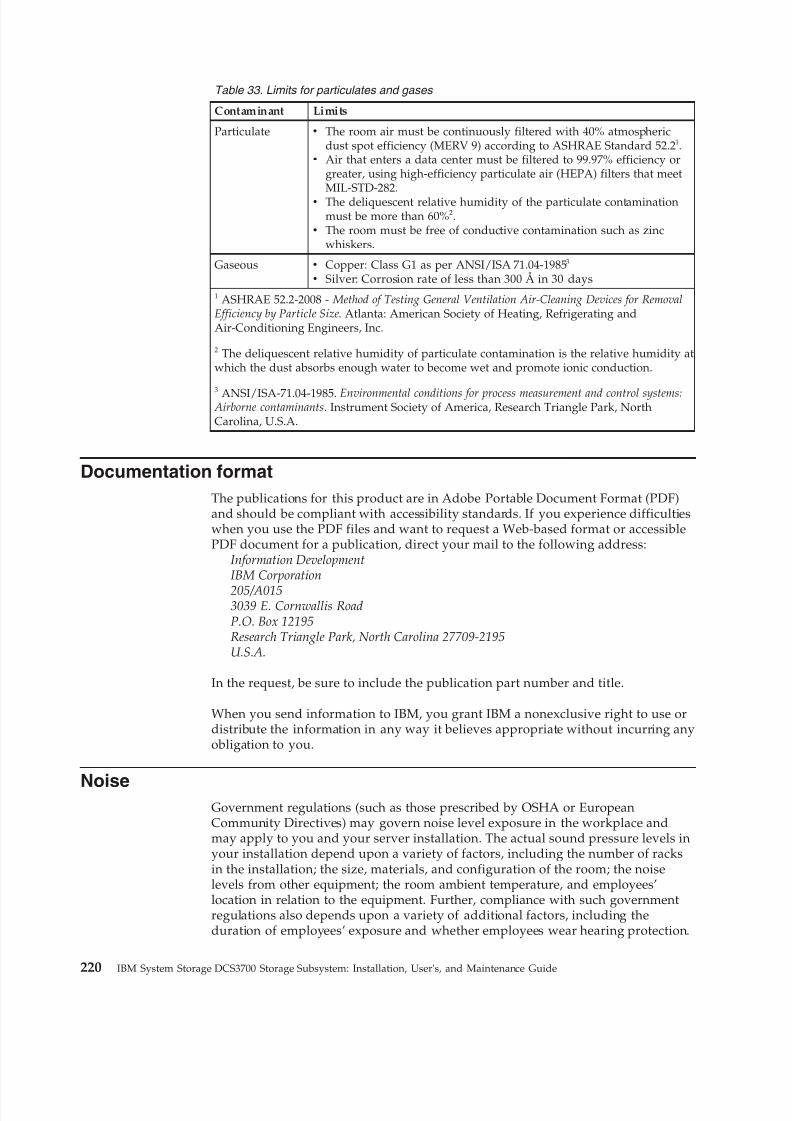
8/9/2019 Installation, User's, And Maintenance
http://slidepdf.com/reader/full/installation-users-and-maintenance 238/262
Table 33. Limits for particulates and gases
Contaminant Limits
Particulate v The room air must be continuously filtered with 40% atmosphericdust spot efficiency (MERV 9) according to ASHRAE Standard 52.21.
v Air that enters a data center must be filtered to 99.97% efficiency orgreater, using high-efficiency particulate air (HEPA) filters that meetMIL-STD-282.
v The deliquescent relative humidity of the particulate contaminationmust be more than 60%2.
v The room must be free of conductive contamination such as zincwhiskers.
Gaseous v Copper: Class G1 as per ANSI/ISA 71.04-19853
v Silver: Corrosion rate of less than 300 Å in 30 days1 ASHRAE 52.2-2008 - Method of Testing General Ventilation Air-Cleaning Devices for RemovalEfficiency by Particle Size. Atlanta: American Society of Heating, Refrigerating andAir-Conditioning Engineers, Inc.
2 The deliquescent relative humidity of particulate contamination is the relative humidity atwhich the dust absorbs enough water to become wet and promote ionic conduction.
3 ANSI/ISA-71.04-1985. Environmental conditions for process measurement and control systems: Airborne contaminants. Instrument Society of America, Research Triangle Park, NorthCarolina, U.S.A.
Documentation format
The publications for this product are in Adobe Portable Document Format (PDF)and should be compliant with accessibility standards. If you experience difficultieswhen you use the PDF files and want to request a Web-based format or accessiblePDF document for a publication, direct your mail to the following address:
Information DevelopmentIBM Corporation
205/A0153039 E. Cornwallis RoadP.O. Box 12195Research Triangle Park, North Carolina 27709-2195U.S.A.
In the request, be sure to include the publication part number and title.
When you send information to IBM, you grant IBM a nonexclusive right to use ordistribute the information in any way it believes appropriate without incurring anyobligation to you.
NoiseGovernment regulations (such as those prescribed by OSHA or EuropeanCommunity Directives) may govern noise level exposure in the workplace andmay apply to you and your server installation. The actual sound pressure levels inyour installation depend upon a variety of factors, including the number of racksin the installation; the size, materials, and configuration of the room; the noiselevels from other equipment; the room ambient temperature, and employees’location in relation to the equipment. Further, compliance with such governmentregulations also depends upon a variety of additional factors, including theduration of employees’ exposure and whether employees wear hearing protection.
220 IBM System Storage DCS3700 Storage Subsystem: Installation, User's, and Maintenance Guide

8/9/2019 Installation, User's, And Maintenance
http://slidepdf.com/reader/full/installation-users-and-maintenance 239/262
IBM recommends that you consult with qualified experts in this field to determinewhether you are in compliance with the applicable regulations.
Electronic emission notices
The following statements apply to this product. The statements for other productsintended for use with this product will appear in their accompanying manuals.
Federal Communications Commission StatementThis explains the Federal Communications Commission's (FCC’s) statement.
This equipment has been tested and found to comply with the limits for a Class Adigital device, pursuant to Part 15 of the FCC Rules. These limits are designed toprovide reasonable protection against harmful interference when the equipment isoperated in a commercial environment. This equipment generates, uses, and canradiate radio frequency energy and, if not installed and used in accordance withthe instruction manual, might cause harmful interference to radio communications.Operation of this equipment in a residential area is likely to cause harmfulinterference, in which case the user will be required to correct the interference at
his own expense.
Properly shielded and grounded cables and connectors must be used in order tomeet FCC emission limits. IBM is not responsible for any radio or televisioninterference caused by using other than recommended cables and connectors, or byunauthorized changes or modifications to this equipment. Unauthorized changesor modifications could void the user's authority to operate the equipment.
This device complies with Part 15 of the FCC Rules. Operation is subject to thefollowing two conditions: (1) this device might not cause harmful interference, and(2) this device must accept any interference received, including interference thatmight cause undesired operation.
Industry Canada Compliance StatementThis Class A digital apparatus complies with Canadian ICES-003.
Cet appareil numérique de la classe A est conform à la norme NMB-003 duCanada.
Australia and New Zealand Class A StatementAttention: This is a Class A product. In a domestic environment this productmight cause radio interference in which case the user might be required to takeadequate measures.
European Union Electromagnetic Compatibility DirectiveThis product is in conformity with the protection requirements of European Union(EU) Council Directive 2004/108/EC on the approximation of the laws of theMember States relating to electromagnetic compatibility. IBM cannot acceptresponsibility for any failure to satisfy the protection requirements resulting from anon-recommended modification of the product, including the fitting of non-IBMoption cards.
Attention: This is an EN 55022 Class A product. In a domestic environment thisproduct might cause radio interference in which case the user might be required totake adequate measures.
Notices 221

8/9/2019 Installation, User's, And Maintenance
http://slidepdf.com/reader/full/installation-users-and-maintenance 240/262
Responsible Manufacturer:
International Business Machines Corp.New Orchard RoadArmonk, New York 10504914-499-1900
European community contact:
IBM Deutschland GmbHTechnical Regulations, Department M372IBM-Allee 1, 71139 Ehningen, GermanyTele: +49 7032 15-2941Email: [email protected]
Germany Electromagnetic Compatibility DirectiveDeutschsprachiger EU Hinweis: Hinweis für Geräte der Klasse A EU-Richtliniezur Elektromagnetischen Verträglichkeit
Dieses Produkt entspricht den Schutzanforderungen der EU-Richtlinie2004/108/EG zur Angleichung der Rechtsvorschriften über die elektromagnetischeVerträglichkeit in den EU-Mitgliedsstaaten und hält die Grenzwerte der EN 55022Klasse A ein.
Um dieses sicherzustellen, sind die Geräte wie in den Handbüchern beschrieben zuinstallieren und zu betreiben. Des Weiteren dürfen auch nur von der IBMempfohlene Kabel angeschlossen werden. IBM übernimmt keine Verantwortung fürdie Einhaltung der Schutzanforderungen, wenn das Produkt ohne Zustimmung derIBM verändert bzw. wenn Erweiterungskomponenten von Fremdherstellern ohneEmpfehlung der IBM gesteckt/eingebaut werden.
EN 55022 Klasse A Geräte müssen mit folgendem Warnhinweis versehen werden:
“Warnung: Dieses ist eine Einrichtung der Klasse A. Diese Einrichtung kann imWohnbereich Funk-Störungen verursachen; in diesem Fall kann vom Betreiberverlangt werden, angemessene Mabnahmen zu ergreifen und dafüraufzukommen.”
Deutschland: Einhaltung des Gesetzes über die elektromagnetischeVerträglichkeit von Geräten
Dieses Produkt entspricht dem “Gesetz über die elektromagnetische Verträglichkeitvon Geräten (EMVG).” Dies ist die Umsetzung der EU-Richtlinie 2004/108/EG inder Bundesrepublik Deutschland.
Zulassungsbescheinigung laut dem Deutschen Gesetz über dieelektromagnetische Verträglichkeit von Geräten (EMVG) (bzw. der EMC EGRichtlinie 2004/108/EG) für Geräte der Klasse A
Dieses Gerät ist berechtigt, in übereinstimmung mit dem Deutschen EMVG dasEG-Konformitätszeichen - CE - zu führen.
Verantwortlich für die Einhaltung der EMV Vorschriften ist der Hersteller:
222 IBM System Storage DCS3700 Storage Subsystem: Installation, User's, and Maintenance Guide
8/9/2019 Installation, User's, And Maintenance
http://slidepdf.com/reader/full/installation-users-and-maintenance 241/262
International Business Machines Corp.New Orchard RoadArmonk,New York 10504Tel: 914-499-1900
Der verantwortliche Ansprechpartner des Herstellers in der EU ist:
IBM Deutschland GmbHTechnical Regulations, Abteilung M372IBM-Allee 1, 71139 Ehningen, GermanyTele: +49 7032 15-2941Email: [email protected]
Generelle Informationen:
Das Gerät erfüllt die Schutzanforderungen nach EN 55024 und EN 55022 KlasseA.
People's Republic of China Class A Statement
Taiwan Class A Statement
Taiwan Contact Information
This topic contains the product service contact information for Taiwan.
IBM Taiwan Product Service Contact Information:IBM Taiwan Corporation3F, No 7, Song Ren Rd., Taipei TaiwanTel: 0800-016-888
Notices 223
8/9/2019 Installation, User's, And Maintenance
http://slidepdf.com/reader/full/installation-users-and-maintenance 242/262
Japan Voluntary Control Council for Interference Class AStatement
This explains the Japan Voluntary Control Council for Interference (VCCI)statement.
Japan Electronics and Information Technology IndustriesAssociation Statement
This explains the Japan Electronics and Information Technology IndustriesAssociation (JEITA) statement for less than or equal to 20 A per phase.
This explains the JEITA statement for greater than 20 A per phase.
Korean Communications Commission Class A StatementThis explains the Korean Communications Commission (KCC) statement.
Russia Electromagnetic Interference Class A StatementThis statement explains the Russia Electromagnetic Interference (EMI) statement.
f 2 c 0 0 7 9 0
j j i e t a 1
j j i e t a 2
224 IBM System Storage DCS3700 Storage Subsystem: Installation, User's, and Maintenance Guide

8/9/2019 Installation, User's, And Maintenance
http://slidepdf.com/reader/full/installation-users-and-maintenance 243/262
r u s e m i
Notices 225

8/9/2019 Installation, User's, And Maintenance
http://slidepdf.com/reader/full/installation-users-and-maintenance 244/262
226 IBM System Storage DCS3700 Storage Subsystem: Installation, User's, and Maintenance Guide
8/9/2019 Installation, User's, And Maintenance
http://slidepdf.com/reader/full/installation-users-and-maintenance 245/262
Glossary
This glossary defines the special terms,abbreviations, and acronyms used in this
publication and other related publications. If youdo not find the term you are looking for, see theIBM Glossary of Computing Terms located at thefollowing Web site:
www.ibm.com/ibm/terminology
The following cross-reference conventions areused in this glossary:
See Refers you to (a) a term that is theexpanded form of an abbreviation oracronym, or (b) a synonym or more
preferred term.See also
Refers you to a related term.
Abstract Windowing Toolkit (AWT)A Java™ graphical user interface (GUI).
accelerated graphics port (AGP)A bus specification that gives low-cost 3Dgraphics cards faster access to mainmemory on personal computers than theusual peripheral component interconnect(PCI) bus. AGP reduces the overall cost of creating high-end graphics subsystems byusing existing system memory.
access volumeA special logical drive that allows thehost-agent to communicate with thecontrollers in the storage subsystem.
adapterA printed circuit assembly that transmitsuser data input/output (I/O) between theinternal bus of the host system and theexternal fibre-channel (FC) link and viceversa. Also called an I/O adapter, host
adapter, or FC adapter.advanced technology (AT) bus architecture
A bus standard for IBM compatibles. Itextends the XT bus architecture to 16 bitsand also allows for bus mastering,although only the first 16 MB of mainmemory are available for direct access.
agent A server program that receives virtualconnections from the network manager(the client program) in a Simple Network
Management Protocol-TransmissionControl Protocol/Internet Protocol
(SNMP-TCP/IP) network-managingenvironment.
AGP See accelerated graphics port.
AL_PASee arbitrated loop physical address.
arbitrated loopOne of three existing fibre-channeltopologies, in which 2 - 126 ports areinterconnected serially in a single loopcircuit. Access to the Fibre ChannelArbitrated Loop (FC-AL) is controlled by
an arbitration scheme. The FC-ALtopology supports all classes of serviceand guarantees in-order delivery of FCframes when the originator and responderare on the same FC-AL. The defaulttopology for the disk array is arbitratedloop. An arbitrated loop is sometimesreferred to as a Stealth Mode.
arbitrated loop physical address (AL_PA)An 8-bit value that is used to uniquelyidentify an individual port within a loop.A loop can have one or more AL_PAs.
array A collection of fibre-channel or SATA harddrives that are logically grouped together.All the drives in the array are assignedthe same RAID level. An array issometimes referred to as a "RAID set." Seealso redundant array of independent disks(RAID), RAID level.
AT See advanced technology (AT) busarchitecture.
ATA See AT-attached.
AT-attached
Peripheral devices that are compatiblewith the original IBM AT computerstandard in which signals on a 40-pinAT-attached (ATA) ribbon cable followedthe timings and constraints of theIndustry Standard Architecture (ISA)system bus on the IBM PC AT computer.Equivalent to integrated drive electronics(IDE).
© Copyright IBM Corp. 2011, 2013 227
8/9/2019 Installation, User's, And Maintenance
http://slidepdf.com/reader/full/installation-users-and-maintenance 246/262
auto-volume transfer/auto-disk transfer(AVT/ADT)
A function that provides automaticfailover in case of controller failure on astorage subsystem.
AVT/ADT
See auto-volume transfer/auto-disk transfer.AWT See Abstract Windowing Toolkit.
basic input/output system (BIOS)The personal computer code that controls
basic hardware operations, such asinteractions with diskette drives, harddisk drives, and the keyboard.
BIOS See basic input/output system.
BOOTPSee bootstrap protocol.
bootstrap protocol (BOOTP)
In Transmission Control Protocol/InternetProtocol (TCP/IP) networking, analternative protocol by which a disklessmachine can obtain its Internet Protocol(IP) address and such configurationinformation as IP addresses of variousservers from a BOOTP server.
bridge A storage area network (SAN) device thatprovides physical and transportconversion, such as fibre channel to smallcomputer system interface (SCSI) bridge.
bridge groupA bridge and the collection of devicesconnected to it.
broadcastThe simultaneous transmission of data tomore than one destination.
cathode ray tube (CRT)A display device in which controlledelectron beams are used to displayalphanumeric or graphical data on anelectroluminescent screen.
client A computer system or process thatrequests a service of another computersystem or process that is typically referredto as a server. Multiple clients can shareaccess to a common server.
commandA statement used to initiate an action orstart a service. A command consists of thecommand name abbreviation, and itsparameters and flags if applicable. A
command can be issued by typing it on acommand line or selecting it from amenu.
community stringThe name of a community contained ineach Simple Network Management
Protocol (SNMP) message.concurrent download
A method of downloading and installingfirmware that does not require the user tostop I/O to the controllers during theprocess.
CRC See cyclic redundancy check .
CRT See cathode ray tube.
CRU See customer replaceable unit.
customer replaceable unit (CRU)An assembly or part that a customer canreplace in its entirety when any of itscomponents fail. Contrast with fieldreplaceable unit (FRU).
cyclic redundancy check (CRC)(1) A redundancy check in which thecheck key is generated by a cyclicalgorithm. (2) An error detectiontechnique performed at both the sendingand receiving stations.
dac See disk array controller.
dar See disk array router.
DASDSee direct access storage device.
data stripingSee striping.
default host groupA logical collection of discovered hostports, defined host computers, anddefined host groups in thestorage-partition topology that fulfill thefollowing requirements:v Are not involved in specific logical
drive-to-LUN mappingsv Share access to logical drives with
default logical drive-to-LUN mappings
device typeIdentifier used to place devices in thephysical map, such as the switch, hub, orstorage.
DHCP See Dynamic Host Configuration Protocol.
228 IBM System Storage DCS3700 Storage Subsystem: Installation, User's, and Maintenance Guide
8/9/2019 Installation, User's, And Maintenance
http://slidepdf.com/reader/full/installation-users-and-maintenance 247/262
direct access storage device (DASD)A device in which access time iseffectively independent of the location of the data. Information is entered andretrieved without reference to previouslyaccessed data. (For example, a disk driveis a DASD, in contrast with a tape drive,
which stores data as a linear sequence.)DASDs include both fixed and removablestorage devices.
direct memory access (DMA)The transfer of data between memory andan input/output (I/O) device withoutprocessor intervention.
disk array controller (dac)A disk array controller device thatrepresents the two controllers of an array.See also disk array router.
disk array router (dar)A disk array router that represents anentire array, including current anddeferred paths to all logical unit numbers(LUNs) (hdisks on AIX®). See also disk array controller.
DMA See direct memory access.
domainThe most significant byte in the node port(N_port) identifier for the fibre-channel(FC) device. It is not used in the fibrechannel-small computer system interface
(FC-SCSI) hardware path ID. It is requiredto be the same for all SCSI targetslogically connected to an FC adapter.
drive channelsThe DS4200, DS4700, DS4800, and DS5000subsystems use dual-port drive channelsthat, from the physical point of view, areconnected in the same way as two driveloops. However, from the point of view of the number of drives and enclosures, theyare treated as a single drive loop insteadof two different drive loops. A group of
storage expansion enclosures areconnected to the DS4000/DS5000 storagesubsystems using a drive channel fromeach controller. This pair of drivechannels is referred to as a redundantdrive channel pair.
drive loopsA drive loop consists of one channel fromeach controller combined to form one pairof redundant drive channels or a
redundant drive loop. Each drive loop isassociated with two ports. Drive loops aremore commonly referred to as drivechannels. See drive channels.
DRAMSee dynamic random access memory.
Dynamic Host Configuration Protocol (DHCP)A protocol defined by the InternetEngineering Task Force that is used fordynamically assigning Internet Protocol(IP) addresses to computers in a network.
dynamic random access memory (DRAM)A storage in which the cells requirerepetitive application of control signals toretain stored data.
ECC See error correction coding.
EEPROM
See electrically erasable programmableread-only memory.
EISA See Extended Industry Standard Architecture.
electrically erasable programmable read-onlymemory (EEPROM)
A type of memory chip which can retainits contents without consistent electricalpower. Unlike the PROM which can beprogrammed only once, the EEPROM can
be erased electrically. Because it can only be reprogrammed a limited number of times before it wears out, it is appropriate
for storing small amounts of data that arechanged infrequently.
electrostatic discharge (ESD)The flow of current that results whenobjects that have a static charge come intoclose enough proximity to discharge.
environmental service module (ESM) canisterA component in a storage expansionenclosure that monitors the environmentalcondition of the components in thatenclosure. Not all storage subsystemshave ESM canisters.
E_port See expansion port.
error correction coding (ECC)A method for encoding data so thattransmission errors can be detected andcorrected by examining the data on thereceiving end. Most ECCs arecharacterized by the maximum number of errors they can detect and correct.
ESD See electrostatic discharge.
Glossary 229
8/9/2019 Installation, User's, And Maintenance
http://slidepdf.com/reader/full/installation-users-and-maintenance 248/262
ESM canisterSee environmental service module canister.
automatic ESM firmware synchronizationWhen you install a new ESM into anexisting storage expansion enclosure in aDS4000® storage subsystem that supports
automatic ESM firmware synchronization,the firmware in the new ESM isautomatically synchronized with thefirmware in the existing ESM.
EXP See storage expansion enclosure.
expansion port (E_port)A port that connects the switches for twofabrics.
Extended Industry Standard Architecture (EISA)A bus standard for IBM compatibles thatextends the Industry StandardArchitecture (ISA) bus architecture to 32
bits and allows more than one centralprocessing unit (CPU) to share the bus.See also Industry Standard Architecture.
fabric A fibre channel entity which interconnectsand facilitates logins of N_ports attachedto it. The fabric is responsible for routingframes between source and destinationN_ports using address information in theframe header. A fabric can be as simple asa point-to-point channel between twoN-ports, or as complex as a frame-routingswitch that provides multiple and
redundant internal pathways within thefabric between F_ports.
fabric port (F_port)In a fabric, an access point for connectinga user's N_port. An F_port facilitatesN_port logins to the fabric from nodesconnected to the fabric. An F_port isaddressable by the N_port connected to it.See also fabric.
FC See Fibre Channel.
FC-AL See arbitrated loop.
feature enable identifierA unique identifier for the storagesubsystem, which is used in the processof generating a premium feature key. Seealso premium feature key.
Fibre Channel (FC)A set of standards for a serialinput/output (I/O) bus capable of transferring data between two ports at upto 100 Mbps, with standards proposals to
go to higher speeds. FC supportspoint-to-point, arbitrated loop, andswitched topologies.
Fibre Channel Arbitrated Loop (FC-AL)See arbitrated loop.
Fibre Channel Protocol (FCP) for small computer
system interface (SCSI)A high-level fibre-channel mapping layer(FC-4) that uses lower-level fibre-channel(FC-PH) services to transmit SCSIcommands, data, and status information
between a SCSI initiator and a SCSI targetacross the FC link by using FC frame andsequence formats.
field replaceable unit (FRU)An assembly that is replaced in itsentirety when any one of its componentsfails. In some cases, a field replaceable
unit might contain other field replaceableunits. Contrast with customer replaceableunit (CRU).
FlashCopyA premium feature for DCS3700 that canmake an instantaneous copy of the datain a volume.
F_port See fabric port.
FRU See field replaceable unit.
GBIC See gigabit interface converter
gigabit interface converter (GBIC)A transceiver that performs serial,optical-to-electrical, andelectrical-to-optical signal conversions forhigh-speed networking. A GBIC can behot swapped. See also small form-factor
pluggable.
Global CopyRefers to a remote logical drive mirrorpair that is set up using Global Copywithout the write consistency groupoption. This is also referred to as'Enhanced Global Mirroring withoutConsistency Group'. Global Copy doesnot ensure that write requests to multipleprimary logical drives are carried out inthe same order on the secondary logicaldrives as they are on the primary logicaldrives. If it is critical that writes to theprimary logical drives are carried out inthe same order in the appropriatesecondary logical drives, Global Mirroring
230 IBM System Storage DCS3700 Storage Subsystem: Installation, User's, and Maintenance Guide
8/9/2019 Installation, User's, And Maintenance
http://slidepdf.com/reader/full/installation-users-and-maintenance 249/262
should be used instead of Global Copy.See also Global Mirroring, remote mirroring,
Metro Mirroring.
Global MirroringRefers to a remote logical drive mirrorpair that is set up using Global Copy with
the write consistency group option. Thisis also referred to as ''Enhanced GlobalMirroring with Consistency Group'.Global Mirroring ensures that writerequests to multiple primary logicaldrives are carried out in the same orderon the secondary logical drives as theyare on the primary logical drives,preventing data on the secondary logicaldrives from becoming inconsistent withthe data on the primary logical drives.See also Global Copy, remote mirroring,
Metro Mirroring.
graphical user interface (GUI)A type of computer interface that presentsa visual metaphor of a real-world scene,often of a desktop, by combininghigh-resolution graphics, pointing devices,menu bars and other menus, overlappingwindows, icons, and the object-actionrelationship.
GUI See graphical user interface.
HBA See host bus adapter.
hdisk An AIX term representing a logical unit
number (LUN) on an array.heterogeneous host environment
A host system in which multiple hostservers, which use different operatingsystems with their own unique diskstorage subsystem settings, connect to thesame DCS3700 storage subsystem at thesame time. See also host.
host A system that is directly attached to thestorage subsystem through a fibre-channelinput/output (I/O) path. This system isused to serve data (typically in the formof files) from the storage subsystem. Asystem can be both a storage managementstation and a host simultaneously.
host bus adapter (HBA)An interface between the fibre-channelnetwork and a workstation or server.
host computerSee host.
host groupAn entity in the storage partitiontopology that defines a logical collectionof host computers that require sharedaccess to one or more logical drives.
host port
Ports that physically reside on the hostadapters and are automatically discovered by the DCS3700 Storage Managersoftware. To give a host computer accessto a partition, its associated host portsmust be defined.
hot swapTo replace a hardware component withoutturning off the system.
hub In a network, a point at which circuits areeither connected or switched. Forexample, in a star network, the hub is the
central node; in a star/ring network, it isthe location of wiring concentrators.
IBMSAN driverThe device driver that is used in a NovellNetWare environment to providemultipath input/output (I/O) support tothe storage controller.
IC See integrated circuit.
IDE See integrated drive electronics.
in-bandTransmission of management protocol
over the fibre-channel transport.Industry Standard Architecture (ISA)
Unofficial name for the bus architecture of the IBM PC/XT personal computer. This
bus design included expansion slots forplugging in various adapter boards. Earlyversions had an 8-bit data path, laterexpanded to 16 bits. The "ExtendedIndustry Standard Architecture" (EISA)further expanded the data path to 32 bits.See also Extended Industry Standard
Architecture.
initial program load (IPL)The initialization procedure that causes anoperating system to commence operation.Also referred to as a system restart,system startup, and boot.
integrated circuit (IC)A microelectronic semiconductor devicethat consists of many interconnectedtransistors and other components. ICs areconstructed on a small rectangle cut from
Glossary 231
8/9/2019 Installation, User's, And Maintenance
http://slidepdf.com/reader/full/installation-users-and-maintenance 250/262
a silicon crystal or other semiconductormaterial. The small size of these circuitsallows high speed, low power dissipation,and reduced manufacturing costcompared with board-level integration.Also known as a chip.
integrated drive electronics (IDE)A disk drive interface based on the 16-bitIBM personal computer Industry StandardArchitecture (ISA) in which the controllerelectronics reside on the drive itself,eliminating the need for a separateadapter card. Also known as anAdvanced Technology AttachmentInterface (ATA).
Internet Protocol (IP)A protocol that routes data through anetwork or interconnected networks. IPacts as an intermediary between thehigher protocol layers and the physicalnetwork.
Internet Protocol (IP) addressThe unique 32-bit address that specifiesthe location of each device or workstationon the Internet. For example, 9.67.97.103is an IP address.
interrupt request (IRQ)A type of input found on manyprocessors that causes the processor tosuspend normal processing temporarily
and start running an interrupt handlerroutine. Some processors have severalinterrupt request inputs that allowdifferent priority interrupts.
IP See Internet Protocol.
IPL See initial program load.
IRQ See interrupt request.
ISA See Industry Standard Architecture.
Java Runtime Environment (JRE)A subset of the Java Development Kit(JDK) for end users and developers whowant to redistribute the Java RuntimeEnvironment (JRE). The JRE consists of the Java virtual machine, the Java CoreClasses, and supporting files.
JRE See Java Runtime Environment.
label A discovered or user entered propertyvalue that is displayed underneath eachdevice in the Physical and Data Pathmaps.
LAN See local area network .
LBA See logical block address.
local area network (LAN)A computer network located on a user'spremises within a limited geographicarea.
logical block address (LBA)The address of a logical block. Logical
block addresses are typically used inhosts' I/O commands. The SCSI diskcommand protocol, for example, useslogical block addresses.
logical partition (LPAR)A subset of a single system that containsresources (processors, memory, andinput/output devices). A logical partitionoperates as an independent system. If hardware requirements are met, multiplelogical partitions can exist within asystem.
A fixed-size portion of a logical volume.A logical partition is the same size as thephysical partitions in its array. Unless thelogical volume of which it is a part ismirrored, each logical partitioncorresponds to, and its contents are storedon, a single physical partition.
One to three physical partitions (copies).The number of logical partitions within a
logical volume is variable.logical unit number (LUN)
An identifier used on a small computersystem interface (SCSI) bus to distinguishamong up to eight devices (logical units)with the same SCSI ID.
loop addressThe unique ID of a node in fibre-channelloop topology sometimes referred to as aloop ID.
loop groupA collection of storage area network(SAN) devices that are interconnectedserially in a single loop circuit.
loop portA node port (N_port) or fabric port(F_port) that supports arbitrated loopfunctions associated with an arbitratedloop topology.
LPAR See logical partition.
LUN See logical unit number.
232 IBM System Storage DCS3700 Storage Subsystem: Installation, User's, and Maintenance Guide
8/9/2019 Installation, User's, And Maintenance
http://slidepdf.com/reader/full/installation-users-and-maintenance 251/262
MAC See medium access control.
management information base (MIB)The information that is on an agent. It isan abstraction of configuration and statusinformation.
man pages
In UNIX-based operating systems, onlinedocumentation for operating systemcommands, subroutines, system calls, fileformats, special files, stand-alone utilities,and miscellaneous facilities. Invoked bythe man command.
MCA See micro channel architecture.
media scanA media scan is a background processthat runs on all logical drives in thestorage subsystem for which it has beenenabled, providing error detection on thedrive media. The media scan processscans all logical drive data to verify that itcan be accessed, and optionally scans thelogical drive redundancy information.
medium access control (MAC)In local area networks (LANs), thesublayer of the data link control layer thatsupports medium-dependent functionsand uses the services of the physical layerto provide services to the logical linkcontrol sublayer. The MAC sublayerincludes the method of determining when
a device has access to the transmissionmedium.
Metro MirroringThis term is used to refer to a remotelogical drive mirror pair which is set upwith Metro Mirror. See also remotemirroring, Global Mirroring.
MIB See management information base.
micro channel architecture (MCA)Hardware that is used for PS/2 Model 50computers and above to provide better
growth potential and performancecharacteristics when compared with theoriginal personal computer design.
Microsoft Cluster Server (MSCS)MSCS, a feature of Windows NT Server(Enterprise Edition), supports theconnection of two servers into a clusterfor higher availability and easiermanageability. MSCS can automaticallydetect and recover from server or
application failures. It can also be used to balance server workload and provide forplanned maintenance.
mini hubAn interface card or port device thatreceives short-wave fiber channel GBICs
or SFPs. These devices enable redundantfibre channel connections from the hostcomputers, either directly or through afibre channel switch or managed hub,over optical fiber cables to the DS4000Storage Server controllers. Each DS4000controller is responsible for two minihubs. Each mini hub has two ports. Fourhost ports (two on each controller)provide a cluster solution without use of a switch. Two host-side mini hubs areshipped as standard. See also host port,
gigabit interface converter (GBIC), small
form-factor pluggable (SFP).mirroring
A fault-tolerance technique in whichinformation on a hard disk is duplicatedon additional hard disks. See also remotemirroring.
model The model identification that is assignedto a device by its manufacturer.
MSCS See Microsoft Cluster Server.
network management station (NMS)In the Simple Network Management
Protocol (SNMP), a station that runsmanagement application programs thatmonitor and control network elements.
NMI See non-maskable interrupt.
NMS See network management station.
non-maskable interrupt (NMI)A hardware interrupt that another servicerequest cannot overrule (mask). An NMI
bypasses and takes priority over interruptrequests generated by software, thekeyboard, and other such devices and is
issued to the microprocessor only indisastrous circumstances, such as severememory errors or impending powerfailures.
node A physical device that allows for thetransmission of data within a network.
node port (N_port)A fibre-channel defined hardware entitythat performs data communications overthe fibre-channel link. It is identifiable by
Glossary 233
8/9/2019 Installation, User's, And Maintenance
http://slidepdf.com/reader/full/installation-users-and-maintenance 252/262
a unique worldwide name. It can act asan originator or a responder.
nonvolatile storage (NVS)A storage device whose contents are notlost when power is cut off.
N_port
See node port.NVS See nonvolatile storage.
NVSRAMNonvolatile storage random accessmemory. See nonvolatile storage.
Object Data Manager (ODM)An AIX proprietary storage mechanismfor ASCII stanza files that are edited aspart of configuring a drive into thekernel.
ODM See Object Data Manager.
out-of-bandTransmission of management protocolsoutside of the fibre-channel network,typically over Ethernet.
partitioningSee storage partition.
parity checkA test to determine whether the numberof ones (or zeros) in an array of binarydigits is odd or even.
A mathematical operation on thenumerical representation of theinformation communicated between twopieces. For example, if parity is odd, anycharacter represented by an even numberhas a bit added to it, making it odd, andan information receiver checks that eachunit of information has an odd value.
PCI local busSee peripheral component interconnect localbus.
PDF See portable document format.
performance eventsEvents related to thresholds set on storagearea network (SAN) performance.
peripheral component interconnect local bus(PCI local bus)
A local bus for PCs, from Intel, thatprovides a high-speed data path betweenthe CPU and up to 10 peripherals (video,disk, network, and so on). The PCI buscoexists in the PC with the Industry
Standard Architecture (ISA) or ExtendedIndustry Standard Architecture (EISA)
bus. ISA and EISA boards plug into anIA® or EISA slot, while high-speed PCIcontrollers plug into a PCI slot. See alsoIndustry Standard Architecture, ExtendedIndustry Standard Architecture.
polling delayThe time in seconds between successivediscovery processes during whichdiscovery is inactive.
port A part of the system unit or remotecontroller to which cables for externaldevices (such as display stations,terminals, printers, switches, or externalstorage units) are attached. The port is anaccess point for data entry or exit. Adevice can contain one or more ports.
portable document format (PDF)A standard specified by Adobe Systems,Incorporated, for the electronicdistribution of documents. PDF files arecompact; can be distributed globally bye-mail, the Web, intranets, or CD-ROM;and can be viewed with the AcrobatReader, which is software from AdobeSystems that can be downloaded at nocost from the Adobe Systems home page.
premium feature keyA file that the storage subsystem
controller uses to enable an authorizedpremium feature. The file contains thefeature enable identifier of the storagesubsystem for which the premium featureis authorized, and data about thepremium feature. See also feature enableidentifier.
private loopA freestanding arbitrated loop with nofabric attachment. See also arbitrated loop.
program temporary fix (PTF)A temporary solution or bypass of a
problem diagnosed by IBM in a currentunaltered release of the program.
PTF See program temporary fix.
RAID See redundant array of independent disks(RAID).
RAID levelAn array's RAID level is a number thatrefers to the method used to achieveredundancy and fault tolerance in the
234 IBM System Storage DCS3700 Storage Subsystem: Installation, User's, and Maintenance Guide
8/9/2019 Installation, User's, And Maintenance
http://slidepdf.com/reader/full/installation-users-and-maintenance 253/262
array. See also array, redundant array of independent disks (RAID).
RAID setSee array.
RAM See random-access memory.
random-access memory (RAM)A temporary storage location in which thecentral processing unit (CPU) stores andexecutes its processes. Contrast withDASD.
RDACSee redundant disk array controller.
read-only memory (ROM)Memory in which stored data cannot bechanged by the user except under specialconditions.
recoverable virtual shared disk (RVSD)
A virtual shared disk on a server nodeconfigured to provide continuous accessto data and file systems in a cluster.
redundant array of independent disks (RAID)A collection of disk drives (array) thatappears as a single volume to the server,which is fault tolerant through anassigned method of data striping,mirroring, or parity checking. Each arrayis assigned a RAID level, which is aspecific number that refers to the methodused to achieve redundancy and fault
tolerance. See also array, parity check,mirroring, RAID level, striping.
redundant disk array controller (RDAC)(1) In hardware, a redundant set of controllers (either active/passive oractive/active). (2) In software, a layer thatmanages the input/output (I/O) throughthe active controller during normaloperation and transparently reroutes I/Osto the other controller in the redundantset if a controller or I/O path fails.
remote mirroring
Online, real-time replication of data between storage subsystems that aremaintained on separate media. TheEnhanced Remote Mirror Option is aDCS3700 premium feature that providessupport for remote mirroring. See alsoGlobal Mirroring, Metro Mirroring.
ROM See read-only memory.
router A computer that determines the path of
network traffic flow. The path selection ismade from several paths based oninformation obtained from specificprotocols, algorithms that attempt toidentify the shortest or best path, andother criteria such as metrics orprotocol-specific destination addresses.
RVSD See recoverable virtual shared disk .
SAI See Storage Array Identifier.
SA IdentifierSee Storage Array Identifier.
SAN See storage area network .
SATA See serial ATA.
scope Defines a group of controllers by theirInternet Protocol (IP) addresses. A scopemust be created and defined so thatdynamic IP addresses can be assigned tocontrollers on the network.
SCSI See small computer system interface.
segmented loop port (SL_port)A port that allows division of afibre-channel private loop into multiplesegments. Each segment can pass framesaround as an independent loop and canconnect through the fabric to othersegments of the same loop.
sense data(1) Data sent with a negative response,
indicating the reason for the response. (2)Data describing an I/O error. Sense datais presented to a host system in responseto a sense request command.
serial ATAThe standard for a high-speed alternativeto small computer system interface (SCSI)hard drives. The SATA-1 standard isequivalent in performance to a 10 000RPM SCSI drive.
serial storage architecture (SSA)An interface specification from IBM inwhich devices are arranged in a ringtopology. SSA, which is compatible withsmall computer system interface (SCSI)devices, allows full-duplex packetmultiplexed serial data transfers at ratesof 20 Mbps in each direction.
server A functional hardware and software unitthat delivers shared resources toworkstation client units on a computernetwork.
Glossary 235
8/9/2019 Installation, User's, And Maintenance
http://slidepdf.com/reader/full/installation-users-and-maintenance 254/262
server/device eventsEvents that occur on the server or adesignated device that meet criteria thatthe user sets.
SFP See small form-factor pluggable.
Simple Network Management Protocol (SNMP)
In the Internet suite of protocols, anetwork management protocol that isused to monitor routers and attachednetworks. SNMP is an application layerprotocol. Information on devices managedis defined and stored in the application'sManagement Information Base (MIB).
SL_portSee segmented loop port.
SMagentThe DCS3700 Storage Manager optional
Java-based host-agent software, which can be used on Microsoft Windows, NovellNetWare, AIX, HP-UX, Solaris, and Linuxon POWER® host systems to managestorage subsystems through the hostfibre-channel connection.
SMclientThe DCS3700 Storage Manager clientsoftware, which is a Java-based graphicaluser interface (GUI) that is used toconfigure, manage, and troubleshootstorage servers and storage expansionenclosures in a DCS3700 storage
subsystem. SMclient can be used on ahost system or on a storage managementstation.
SMruntimeA Java compiler for the SMclient.
SMutilThe DCS3700 Storage Manager utilitysoftware that is used on MicrosoftWindows, AIX, HP-UX, Solaris, and Linuxon POWER host systems to register andmap new logical drives to the operatingsystem. In Microsoft Windows, it alsocontains a utility to flush the cached dataof the operating system for a particulardrive before creating a FlashCopy.
small computer system interface (SCSI)A standard hardware interface thatenables a variety of peripheral devices tocommunicate with one another.
small form-factor pluggable (SFP)An optical transceiver that is used to
convert signals between optical fibercables and switches. An SFP is smallerthan a gigabit interface converter (GBIC).See also gigabit interface converter.
SNMPSee Simple Network Management Protocol
and SNMPv1.SNMP trap event
An event notification sent by the SNMPagent that identifies conditions, such asthresholds, that exceed a predeterminedvalue. See also Simple Network
Management Protocol.
SNMPv1The original standard for SNMP is nowreferred to as SNMPv1, as opposed toSNMPv2, a revision of SNMP. See alsoSimple Network Management Protocol.
SRAMSee static random access memory.
SSA See serial storage architecture.
static random access memory (SRAM)Random access memory based on thelogic circuit know as flip-flop. It is calledstatic because it retains a value as long aspower is supplied, unlike dynamicrandom access memory (DRAM), whichmust be regularly refreshed. It is however,still volatile, meaning that it can lose its
contents when the power is turned off.storage area network (SAN)
A dedicated storage network tailored to aspecific environment, combining servers,storage products, networking products,software, and services. See also fabric.
Storage Array Identifier (SAI or SA Identifier)The Storage Array Identifier is theidentification value used by the DCS3700Storage Manager host software (SMClient)to uniquely identify each managedstorage server. The DCS3700 StorageManager SMClient program maintainsStorage Array Identifier records of previously-discovered storage servers inthe host resident file, which allows it toretain discovery information in apersistent fashion.
storage expansion enclosure (EXP)A feature that can be connected to asystem unit to provide additional storageand processing capacity.
236 IBM System Storage DCS3700 Storage Subsystem: Installation, User's, and Maintenance Guide
8/9/2019 Installation, User's, And Maintenance
http://slidepdf.com/reader/full/installation-users-and-maintenance 255/262
storage management stationA system that is used to manage thestorage subsystem. A storage managementstation does not need to be attached tothe storage subsystem through thefibre-channel input/output (I/O) path.
storage partitionStorage subsystem logical drives that arevisible to a host computer or are sharedamong host computers that are part of ahost group.
storage partition topologyIn the DCS3700 Storage Manager client,the Topology view of the Mappingswindow displays the default host group,the defined host group, the hostcomputer, and host-port nodes. The hostport, host computer, and host grouptopological elements must be defined togrant access to host computers and hostgroups using logical drive-to-LUNmappings.
stripingSplitting data to be written into equal
blocks and writing blocks simultaneouslyto separate disk drives. Stripingmaximizes performance to the disks.Reading the data back is also scheduledin parallel, with a block being readconcurrently from each disk thenreassembled at the host.
subnetAn interconnected but independentsegment of a network that is identified byits Internet Protocol (IP) address.
sweep methodA method of sending Simple NetworkManagement Protocol (SNMP) requestsfor information to all the devices on asubnet by sending the request to everydevice in the network.
switch A fibre-channel device that provides full
bandwidth per port and high-speedrouting of data by using link-leveladdressing.
switch groupA switch and the collection of devicesconnected to it that are not in othergroups.
switch zoningSee zoning.
system nameDevice name assigned by the vendor'sthird-party software.
TCP See Transmission Control Protocol.
TCP/IPSee Transmission Control Protocol/Internet
Protocol.terminate and stay resident program (TSRprogram)
A program that installs part of itself as anextension of DOS when it is executed.
topologyThe physical or logical arrangement of devices on a network. The threefibre-channel topologies are fabric,arbitrated loop, and point-to-point. Thedefault topology for the disk array isarbitrated loop.
TL_portSee translated loop port.
transceiverA device that is used to transmit andreceive data. Transceiver is anabbreviation of transmitter-receiver.
translated loop port (TL_port)A port that connects to a private loop andallows connectivity between the privateloop devices and off loop devices (devicesnot connected to that particular TL_port).
Transmission Control Protocol (TCP)A communication protocol used in theInternet and in any network that followsthe Internet Engineering Task Force (IETF)standards for internetwork protocol. TCPprovides a reliable host-to-host protocol
between hosts in packed-switchedcommunication networks and ininterconnected systems of such networks.It uses the Internet Protocol (IP) as theunderlying protocol.
Transmission Control Protocol/Internet Protocol
(TCP/IP)A set of communication protocols thatprovide peer-to-peer connectivityfunctions for both local and wide-areanetworks.
trap In the Simple Network ManagementProtocol (SNMP), a message sent by amanaged node (agent function) to amanagement station to report anexception condition.
Glossary 237
8/9/2019 Installation, User's, And Maintenance
http://slidepdf.com/reader/full/installation-users-and-maintenance 256/262
trap recipientReceiver of a forwarded Simple NetworkManagement Protocol (SNMP) trap.Specifically, a trap receiver is defined byan Internet Protocol (IP) address and portto which traps are sent. Presumably, theactual recipient is a software application
running at the IP address and listening tothe port.
TSR programSee terminate and stay resident program.
uninterruptible power supplyA source of power from a battery that isinstalled between a computer system andits power source. The uninterruptiblepower supply keeps the system running if a commercial power failure occurs, untilan orderly shutdown of the system can beperformed.
user action eventsActions that the user takes, such aschanges in the storage area network(SAN), changed settings, and so on.
worldwide port name (WWPN)A unique identifier for a switch on localand global networks.
worldwide name (WWN)A globally unique 64-bit identifierassigned to each fibre channel port.
WORMSee write-once read-many.
write-once read many (WORM)Any type of storage medium to whichdata can be written only a single time, butcan be read from any number of times.After the data is recorded, it cannot bealtered.
WWN See worldwide name.
zoningIn fibre channel environments, thegrouping of multiple ports to form avirtual, private, storage network. Portsthat are members of a zone cancommunicate with each other, but areisolated from ports in other zones.
A function that allows segmentation of nodes by address, name, or physical portand is provided by fabric switches orhubs.
238 IBM System Storage DCS3700 Storage Subsystem: Installation, User's, and Maintenance Guide
8/9/2019 Installation, User's, And Maintenance
http://slidepdf.com/reader/full/installation-users-and-maintenance 257/262
Index
Numerics6 Gbps SAS host port 12
8 Gbps FC host port 12
Aaccessible documentation 220acoustical noise emission values 24airflow 15, 23, 25altitude ranges 22area requirements 21
B battery 158 battery, replacing 127
best practices 6 bezel, replacing 132 blank trays 112
Ccabling
an IBM DCS3700 56cache active LED 90cache backup flash memory device
removing 131replacing 131
cache battery backup module 13cache battery learn cycle 91cache memory 13, 90
Cache Memory DIMMreplacing on a subsystem with
Performance ModuleControllers 153
caution and danger noticessafety and caution ix
chassis, enclosure 141checking the LEDs 81codes
category 188detail 188
Component weights for DCS3700 215components
replacing 99upgrading, replacing on a subsystem
with Performance ModuleControllers 147weights 21
connectorsESM 59
contamination, particulate andgaseous 220
controller 158information record 196LEDs 82removing 100replacing 102, 148
controller cache battery 90
controller connectorsFibre channel host port adapters 49iSCSI host port adapters 48
controller coverinstalling 101removal 101
controllerslocation 10
controllers connectorsSAS host port adapters 47
controllers, working with 99cooling 25customer replaceable units (CRUs)
replacing a controller 102, 148replacing the battery 127
Ddata sheet 196DCS3700
cabling 59components 7dimensions 21environmental requirements and
specifications 22features 2front LEDs 82
DDM2 or 4 Gbps 9replacing all at same time 118replacing one at a time 118, 120
device drivers, downloading latestversions xvi
devices, installing and replacing 99diagnostic code 188DIMM
installing 131removing 129
disk drive2 or 4 Gbps 9drawers 8hot-swap 9LEDs 88
disposing of the system-board lithium battery 106
documentationfinding documents xviformat 220
Web site xviidrawers, disk drive 8drive 158
drawer LEDs 87drawers 8FRUs 112hard disk, replacing all at same
time 118hard disk, replacing one at a
time 120hard disk,replacing one at a time 118ID 14installation 43
drive (continued)LED activity 113LEDs 112
drive drawerreplacing 135
drivers xvidual-controller
direct-attached 68dual-controller configuration
adding storage enclosure 62
EEIA 310-D Type A 19-inch rack
cabinet 35electrical requirements 24emergency shutdown 94
enclosure 158enclosure chassis 141enclosure ID Settings 50environmental requirements and
specifications 22environmental service module (ESM)
description 13location 13working with 133
ESMfirmware updates 80LEDs 85replacing 133working with 133
ethernetports 12
Ethernet port 10expansion enclosure
connect 60expansion ports 12
Ffan assembly
description 15replacing 134
Fan assemblyLEDs 86
Features 1Fibre Channel hosts
connecting 70Fibre Channel overview 2fibre-optic cable, handling 55field replaceable units (FRUs) 186fire suppression xviiifirmware levels, determining 20firmware updates 80front LEDS, checking 82FRUs 186
© Copyright IBM Corp. 2011, 2013 239
8/9/2019 Installation, User's, And Maintenance
http://slidepdf.com/reader/full/installation-users-and-maintenance 258/262
Ggaseous contamination 220general checkout 175glossary 227guidelines, fibre-optic cables 55
Hhandlesinstall 40remove 40
hard disk driveinstallation 43replacing all at same time 118replacing one at a time 118, 120
hardwarefault indicator LEDs 81inspection 76maintenance 175service and support xviii
hardware tools 33Health Check process 75heat dissipation 23heat output 25HIC card
install on a subsystem withPerformance ModuleControllers 165
replace on a subsystem withPerformance ModuleControllers 165
host bus adapter 34host interface adapter
installing 108replacing 110
hot-swapcontrollers 99DDM, replacing 116
DDMs 112disk drives 9drive LED activity described 113hard disk drive, replacing 116hard disk drives 112hardware 113, 116power supplies 99, 122
IIBM
notices 217System Storage DCS3700 hardware
inspection 76System Storage DCS3700 Health
Check process 75System Storage DCS3700 powering
on 77System Storage Productivity
Center xviiIBM BladeCenter
Connecting 69Installing 69overview 69
identification numbers 195indicator LEDs, during power on 81indicator lights, power supply 15
information record, storage subsystemand controller 196
installationinto a rack 41into a rack cabinet 27preparation 30
Installation overview 27Installation sequence 29
installed device records 197installing and replacing devicesa drive drawer 135a fan assembly 134all DDMs at the same time 118 battery 127 blank trays 112cache backup flash memory
device 131components 99controllers 102, 148DDMs 112DIMM 129drives, one at a time 120host interface adapter 110host interface adapters 108hot-swap hard disk drives 116memory cache DIMM 129mulitple DDMs 117power supplies 122
inventory checklist 5, 32Inventory list 32
LLC-LC Fibre Channel cable 56
connecting to an SFP 57removing 58
LEDsAC power-supply 86disk drive 88drive drawer 87ESM 85fan assembly 86front of DCS3700 82seven-segment numeric display 89
lift tool 28lift tool order 28
United States 28loop redundancy 47
Mmanagement method
Direct (out-of-band) 66
Host-agent (in-band) 65memory cache DIMMinstalling and replacing 129
multiple DDMs, replacing 117multiple drives, replacing all at same
time 117My Support 6
Nnon-IBM rack installation 203notes, important 219notices 217
notices (continued)general 217IBM 217patents 217safety and caution ix
numbers, drive ID 14
Ooperating 75operating system support 2overview of the product 1
Ppart numbers, power cords 211particulate contamination 220parts listing 186Performance Module Controllers
Upgrading 147power
cords 211recovery 94redundancy 7requirements 25
power cord routing 34power cord use by country 211power cords and receptacles 25power recovery 25power supply
cabling 74description 15LEDs 86recovering from overheated power
supply 95replacing 122
powering on 77problem determination 175
product overview 1
Rrack cabinet
EIA 310-D Type A 19 inch 35preparatory procedures 34rail installation 35site preparation 30
rack mounting template forDCS3700 199
rack specifications 205RAID controllers 47rail installation 35records
identification numbers 195installed device 197
redundant connectionsSAN fabric dual-controller 71
Redundant drive channel pair 64replace on a subsystem with Performance
Module Controllers 158replacing 141replacing components
battery 127 bezel 132controller 102, 148DIMM 129, 131
240 IBM System Storage DCS3700 Storage Subsystem: Installation, User's, and Maintenance Guide
8/9/2019 Installation, User's, And Maintenance
http://slidepdf.com/reader/full/installation-users-and-maintenance 259/262
replacing components (continued)drive drawer 135ESM 133fan assembly 134power supply 122Service Action Allowed Status
LED 99system-board lithium battery 106
resourcesdocuments xviWeb site xvii
Ssafety requirements
non-IBM 203safety, static-sensitive devices 30sample information record 197SAS cables 50SAS hosts
connecting 67SAS overview 2SAS port 10
secondary interface cablesconnect 64sequence codes 188serial port 12seven-segment numeric display 89, 188SFP modules, described 17shipping box, unpacking 31shipping dimensions 22shock and vibrations requirements 23site preparation 34site wiring requirements 25small form-factor pluggable module (SFP)
connecting an LC-LC Fibre Channelcable 57
described 17important information about 52protective cap 52removal 54removing an LC-LC cable 58static-protective package 52
software service and support xviisolving problems 175specifications 20Specifications 1specifications, fibre-optic cables 55SSPC (System Storage Productivity
Center) xviistatic-sensitive devices, handling 30storage expansion enclosure
airflow 15cabling 47
checking status 81drive ID numbers 14fans 15fault indicator LEDs 81identification numbers 195power supplies 15records 195turning on before storage
subsystem 120Storage Manager
installing for use with IBM SystemStorage Productivity Center xvii
Storage Manager softwaremonitoring status 79Storage Manager Client 79where to obtain xvi
storage manager software and hardwarecompatibility 18
storage subsystemcabling 59
configuring 64information record 196monitoring status 79troubleshooting 81turning off 91
storage subsystem managementmethods 64
subsystemrelocating 74
subsystem configurationinstalling 66
support code upgradessoftware and firmware 18
support notifications 6support rails
install 35switches 34System Storage Productivity Center xvii
Ttemperature and humidity 22template, rack mounting 199tools 33trademarks 218troubleshooting 81, 175turning off the storage subsystem 91
Uuninterruptible power supply (UPS) 34updates (product updates) 6upgrades, support code 18user controls 13
WWeb sites, list xviiworking with controllers 99working with environmental service
modules 133
Index 241

8/9/2019 Installation, User's, And Maintenance
http://slidepdf.com/reader/full/installation-users-and-maintenance 260/262
242 IBM System Storage DCS3700 Storage Subsystem: Installation, User's, and Maintenance Guide

8/9/2019 Installation, User's, And Maintenance
http://slidepdf.com/reader/full/installation-users-and-maintenance 261/262
8/9/2019 Installation, User's, And Maintenance
http://slidepdf.com/reader/full/installation-users-and-maintenance 262/262