installation version 1 starter 2016 odyssey …€¦ · 2016 odyssey july 2015. parts list remote...
TRANSCRIPT

Publications No.
INSTALLATIONINSTRUCTIONS
Accessory Application
© 2015 American Honda Motor Co., Inc. – All Rights Re
VERSION 1
REMOTE CONTROL ENGINESTARTERserved. AII02125-20 (150
2016 ODYSSEY
7) 0
Issue Date
JULY 2015
PARTS LIST
Remote Engine Starter Unit KitP/N 08E91-E54-100
Transmitter
Control unit
Antenna
ID label
Remote Control Engine Starter Attachment KitP/N 08E92-TK8-100A
Engine starter harness
Control unit bracket
3 Relays
23 Wire ties
Aluminum tape
4 Urethane tapes
Caution label
Fuse label
Accessory User’s Information Manual
Quick Start Guide
1 of 228E92-TK8-1A00-90

TOOLS AND SUPPLIES REQUIRED
Phillips screwdriver
Flat-tip screwdriver
Diagonal cutters
Ratchet
8 mm, 10 mm, and 12 mm Sockets
10 mm Open end wrench
Isopropyl alcohol
Scissors
Shop towel
Ruler
Tape measure
HDS/MVCI
Torque wrench
Masking tape
Felt-tip pen
The following tools are available through the Honda Tooland Equipment Program. On the iN, click on: Service >Service Bay > Tool and Equipment Program, then enterthe number under “Search”. Or, call 888-424-6857.
• Trim Tool Set (T/N SOJATP2014)
• Plastic Trim Tool (T/N SILTRIMTL10)
Illustration of the Remote Control Engine StarterInstalled on the Vehicle
QC11807BB
ANTENNA
3 RELAYS3 A FUSE
CONTROLUNIT
20 AFUSES
ENGINE STARTERHARNESS
2 of 22 AII02125-2
INSTALLATION
Customer Information: The information in thisinstallation instruction is intended for use only by skilledtechnicians who have the proper tools, equipment, andtraining to correctly and safely add equipment to yourvehicle. These procedures should not be attempted by“do-it-yourselfers.”
NOTE: This antenna should only be installed if theambient air temperature 15°C (60°F) or above.
1. Move the driver’s seat all the way back.
2. Open the hood and remove the air duct (two clips).
QC10807AY
2 CLIPS
AIR DUCT
3. Disconnect the negative cable from the battery.
0 (1507) © 2015 American Honda Motor Co., Inc. – All Rights Reserved.

4. Attach the ID label.
• Using isopropyl alcohol on a shop towel, cleanthe area where the ID label will attach.
• Attach the ID label to the transmitter in the areaas shown.
QBD0601AE
ID LABEL
TRANSMITTER
Clean withisopropylalcohol.
© 2015 American Honda Motor Co., Inc. – All Rights Reserved. AII02125-2
5. Remove the roof console.
• Using a small flat-tip screwdriver wrapped with ashop towel, pry out and remove the left and rightlens (four retaining tabs each).
• Open the sunglass holder and remove the fourscrews.
• Remove the roof console (unplug the vehicleconnectors).
012802BX
VEHICLECONNECTORS
ROOFCONSOLE
4 SCREWS
4 RETAININGTABS
LEFT LENS
RIGHT LENS
4 RETAININGTABS
SUNGLASSHOLDER(Open.)
6. Rotate the sunvisor holders 45° counterclockwiseand remove the two sunvisor holders.
700215AE
Rotate.
DRIVER’SSUNVISORHOLDER
PASSENGER’SSUNVISORHOLDER
2 SUNVISORHOLDERS
0 (1507) 3 of 22

7. Remove the driver’s sunvisor.
• Turn the sunvisor toward the driver’s seat.
• Locate the slot in the sunvisor holder, and inserta flat-tip screwdriver into the slot. Push in andhold the retaining tab.
• While holding the retaining tab, push up on thesunvisor and rotate toward the door to remove.NOTE: If the retaining tab did not stay pushed in,return the driver’s sunvisor to its original positionand repeat the above steps.
• Remove the driver’s sunvisor (unplug the vehicleconnector).
021002BYDRIVER’SSUNVISOR
FRONT
VEHICLECONNECTOR
SLOT
HOLDER
Push and hold theretaining tab.
FLAT-TIPSCREWDRIVER
Rotate.
Push andhold.
Rotatetowardsthe door.
FRONT
FRONT
4 of 22 AII02125-2
8. Pull away the door opening seal from around thedriver’s A-pillar trim. Using a trim tool, remove theA-pillar cover (two retaining tabs and one hook).
021003BY
A-PILLAR COVER HOOK
2 RETAININGTABS
WASHER-BOLT
DRIVER’SA-PILLARTRIM
DOOR OPENING SEAL(Pull away.)
TRIMTOOL
A-PILLARCOVER
9. Remove the washer-bolt from the driver’s A-pillar.
10. Remove the driver’s A-pillar trim (three clips).
021004CY
DRIVER’SA-PILLARTRIM
CLIP
2 CLIPS
0 (1507) © 2015 American Honda Motor Co., Inc. – All Rights Reserved.

11. Lower the tilt lever and pull down the steering wheel.
021001AB
STEERING COLUMNUPPER COVER
4 RETAININGTABS
2 SELF-TAPPINGSCREWS
Push.
STEERING WHEEL
12. Remove the steering column upper cover (two self-tapping screws and four retaining tabs).NOTE: Adjust the angle of the steering wheel (rightor left) to access each self-tapping screw.
13. Remove the steering column lower cover (threewasher-screws).
021002BB 3 WASHER-SCREWS
STEERING COLUMNLOWER COVER
© 2015 American Honda Motor Co., Inc. – All Rights Reserved. AII02125-2
14. Remove the driver’s dashboard side panel (one clip,two clips, four retaining tabs, and one pin).
012702BE
4 RETAININGTABS
PIN
2 CLIPSDRIVER’SDASHBOARDSIDE PANEL
CLIP
0 (1507) 5 of 22

Routing the Engine Starter Harness
15. Using isopropyl alcohol on a shop towel, thoroughlyclean the fuse block and the fuse case where the 20A fuse labels and 3 A fuse label will attach.
QC11401AB
20 A FUSELABEL
RELAYBLOCK
ENGINESTARTERHARNESS
FUSECASE
3 A FUSELABEL
3 RELAYS
Clean withisopropyl alcohol.
Clean withisopropylalcohol.
20 A FUSELABEL
16. Attach the 20 A fuse labels, and the 3 A fuse label tothe fuse block, and the fuse case on the enginestarter harness.
17. Plug three relays into the relay block on the enginestarter harness.
6 of 22 AII02125-2
18. Route the engine starter harness under thedashboard as shown.
QC11402AB
FUSEBOX
PARKING BRAKEBRACKET
ENGINE STARTERHARNESS
BRAKEPEDAL
19. Secure the clip from the engine starter harness relayblock to the hole in the parking brake bracket.
QC11403AB
FUSEBOX
PARKING BRAKEBRACKET
BRAKEPEDAL CLIP
RELAYBLOCK
ENGINESTARTERHARNESS
HOLE
0 (1507) © 2015 American Honda Motor Co., Inc. – All Rights Reserved.

20. Secure the engine starter harness to the vehicleharness with one wire tie.
QC11404AB
PARKING BRAKEBRACKET
FUSEBOX BRAKE
PEDAL
ENGINESTARTERHARNESS
VEHICLEHARNESS
WIRETIE
21. Align the white tape on the engine starter harnesswith the vehicle clip, and secure the engine starterharness to the vehicle harness with one wire tie.
QC11405BB
STEERING COLUMN LOWERCOVER OPENING
WIRE TIE
WHITE TAPE(Align.)
ENGINESTARTERHARNESS
VEHICLE CLIP
VEHICLEHARNESS
© 2015 American Honda Motor Co., Inc. – All Rights Reserved. AII02125-2
22. Align the white tape on the engine starter harnesswith the vehicle clip, and secure the engine starterharness to the vehicle harness with one wire tie asshown.
QC11410BB
WIRETIE
ENGINESTARTERHARNESS
VEHICLEHARNESS
VEHICLECLIP
WHITETAPE(Align.)
WIRETIE
23. Secure the engine starter harness to the vehicleharness with one wire tie.
24. Route the engine starter harness up the steeringcolumn.
QC11407AB
STEERINGCOLUMN UPPERCOVER OPENING
ENGINE STARTERHARNESS 8-PINCONNECTORS
VEHICLE 8-PINCONNECTOR
STEERINGWHEEL
WIPER SWITCH
25. Unplug the vehicle 8-pin connector from the wiperswitch, and plug it into the engine starter harness8-pin connector. Plug the remaining engine starterharness 8-pin connector into the wiper switch.
0 (1507) 7 of 22

26. Unplug the cable reel 20-pin connector, and releasethe harness cover (two clips).
021202BYSTEERINGCOLUMN UPPERCOVER OPENING
STEERINGWHEEL
HARNESSCOVER
CLIP
CLIP
CABLE REEL20-PINCONNECTOR
27. Route the engine starter harness through thesteering column area as shown.
021203BY
ENGINESTARTERHARNESS12-PINCONNECTORS
VEHICLE 12-PINCONNECTOR
ENGINESTARTERHARNESS
STEERINGCOLUMN UPPERCOVER OPENING
STEERINGWHEEL
ENGINESTARTERHARNESS
VEHICLEHARNESS
LIGHTSWITCH
HARNESSCOVER
28. Unplug the vehicle 12-pin connector from the lightswitch, and plug it into the engine starter harness12-pin connector. Plug the remaining engine starterharness 12-pin connector into the light switch.
8 of 22 AII02125-2
29. Secure the 12-pin connectors and the engine starterharness with one wire tie.
QC11408AB
Do not unduestrain to the 12-pinconnector cord.
STEERINGWHEEL12-PIN
CONNECTORS ENGINESTARTERHARNESS
WIRETIE
30. Reinstall the harness cover, and re-plug the cablereel 20-pin connector unplugged in step 26.
0 (1507) © 2015 American Honda Motor Co., Inc. – All Rights Reserved.

31. Secure the 8-pin connector and engine starterharness to the vehicle harness with one wire tie asshown.NOTE: Make sure that the connectors and harnessare not pinched, or interfering the steering wheelwhen moved for adjustment.
QC11409AB
ENGINESTARTERHARNESS
VEHICLEHARNESSWIRE
TIESTEERINGWHEEL
FRONT
8-PINCONNECTORS
TAPE
Do not unduestrain to the 8-pinconnector cord.
© 2015 American Honda Motor Co., Inc. – All Rights Reserved. AII02125-2
32. Secure the engine starter harness to the vehicleharness with one wire tie.
QC11406AB
FUSE BOX
PARKINGBRAKEBRACKET
ENGINESTARTERHARNESS
VEHICLEHARNESS
2 WIRE TIES(Looselysecure.)
WIRETIE
DRIVER’SKICK PANEL
33. Loosely secure the engine starter harness to thevehicle harness with two wire ties.
34. Route the engine starter harness up, and looselysecure it to the vehicle harness with one wire tie.
QC11501AB
ENGINE STARTERHARNESS 12-PINCONNECTORS
ENGINESTARTERHARNESS
FUSEBOX
VEHICLEHARNESS
WIRE TIE(Loosely secure.)
WIRE TIE
35. Secure the engine starter harness to the vehicleharness with one wire tie.
0 (1507) 9 of 22

36. Route the engine starter harness, and looselysecure it to the vehicle harness with one wire tie.
QC11502AB
ENGINE STARTERHARNESS
FUSEBOX
VEHICLEHARNESSWIRE TIE
(Loosely secure.)
37. Using isopropyl alcohol on a shop towel, thoroughlyclean the left knee bolster where the urethane tapewill attach. Attach the one urethane tape to the leftknee bolster as shown.
QC11503AB
URETHANETAPE
FUSEBOX
DASHBOARD
Clean withisopropylalcohol.
HOLE
LEFT KNEEBOLSTER
RELAY UNIT
10 of 22 AII02125-2
38. Unplug the vehicle 2-pin connector from the relayunit, and plug it into the engine starter harness 2-pinconnector. Plug the remaining engine starterharness 2-pin connector into the relay unit.
QC11504ABVEHICLE 2-PINCONNECTOR
FUSEBOX
RELAY UNITENGINE STARTERHARNESS 2-PINCONNECTOR
ENGINE STARTERHARNESS 2-PINCONNECTOR
39. Unplug the vehicle 4-pin connector from the relayunit, and plug it into the engine starter harness 4-pinconnector. Plug the remaining engine starterharness 4-pin connector into the relay unit.
QC11505ABVEHICLE 4-PINCONNECTOR
FUSEBOX
RELAY UNITENGINE STARTERHARNESS 4-PINCONNECTOR
ENGINE STARTERHARNESS 4-PINCONNECTOR
0 (1507) © 2015 American Honda Motor Co., Inc. – All Rights Reserved.

40. Locate the 4-pin connector taped to the vehicleharness, and remove the tape to release theconnector. Plug the engine starter harness 4-pinconnector into the vehicle 4-pin connector.
QC11506AB
4-PINCONNECTORS
FUSEBOX
VEHICLEHARNESS
VEHICLEHARNESS
TAPE(Remove.)
VEHICLE 4-PINCONNECTOR
WIRE TIE(Looselysecure.)
ENGINE STARTERHARNESS 4-PINCONNECTOR
41. Loosely secure the 4-pin connectors to the vehicleharness with one wire tie.
42. Route the engine starter harness across thedashboard as shown.
QC11507AB
ENGINE STARTERHARNESS
OBD IIDATA LINKCONNECTOR
DASHBOARDLEFT KNEEBOLSTER
ENGINE STARTERHARNESS 12-PINCONNECTORS
© 2015 American Honda Motor Co., Inc. – All Rights Reserved. AII02125-2
43. Align the white tape on the engine starter harnesswith the hole on the vehicle bracket, and secure theengine starter harness to the vehicle bracket withone wire tie.
021213BY
ENGINESTARTERHARNESS
WHITETAPE
WIRETIE
VEHICLEBRACKET
HOLE
WHITETAPE(Align.)
VEHICLEBRACKET
OBD IIDATA LINKCONNECTOR
If the vehicle is equipped with the ambient light, go to step45; otherwise, continue with step 44.
44. Secure the engine starter harness to the dashboardwith one wire tie. Go to step 46.
021214BY
ENGINE STARTERHARNESS
WIRE TIE
DASHBOARD
0 (1507) 11 of 22

45. Secure the engine starter harness to the ambientlight harness with one wire tie.
021215BY
ENGINE STARTERHARNESS WIRE TIE
AMBIENT LIGHT AMBIENT LIGHTHARNESS
46. Using isopropyl alcohol on a shop towel, thoroughlyclean the left knee bolster where the aluminum tapewill attach. Attach the engine starter harness to theinside of the left knee bolster with the aluminum tape.
QC11508AB
ENGINESTARTERHARNESS
ALUMINUMTAPE
LEFT KNEEBOLSTER
ENGINESTARTERHARNESS
ALUMINUMTAPE
LEFT KNEEBOLSTER(Clean withisopropyl alcohol.)
12 of 22 AII02125-2
47. Continue routing the engine starter harness asshown.
021217CY ENGINE STARTERHARNESS
VEHICLE12-PINCONNECTOR
ENGINESTARTERHARNESS12-PINCONNECTORS
DRIVER’S DASHBOARDSIDE PANEL OPENING
SELECT LEVER
48. Unplug the vehicle 12-pin connector from the selectlever, and plug it into the engine starter harness12-pin connector. Plug the remaining engine starterharness 12-pin connector into the select lever.
49. Align the branch section of the engine starterharness to the branch section of the vehicle harnessand secure the engine starter harness to the vehicleharness with two wire ties.
021218CY
ENGINESTARTERHARNESS
DRIVER’SDASHBOARD SIDEPANEL OPENINGVEHICLE
HARNESS
2 WIRETIES
VEHICLECLIP
ENGINESTARTERHARNESS
VEHICLEHARNESS
BRANCHSECTION(Align.)
0 (1507) © 2015 American Honda Motor Co., Inc. – All Rights Reserved.

Installing the Antenna
50. Using scissors, cut one urethane tape in half. Wraptwo halves of urethane tape to the antenna cable asshown.
QB62501BK
ANTENNA
60 mm(2.4 in.)
60 mm(2.4 in.)
HALVES OFURETHANE TAPE(Do not foldthe antenna cable.)
URETHANE TAPE(Cut in half.)
ANTENNACABLE
51. Using scissors, cut two urethane tapes in half. Wrapfour halves of urethane tape around the antennacable at the measurements shown.
QC11509AB
ANTENNA
15 mm(0.6 in.)
770 mm(30.3 in.)
ANTENNACABLE
HALVES OFURETHANE TAPE
2 URETHANE TAPES(Cut in half.)
15 mm(0.6 in.)
15 mm(0.6 in.)
© 2015 American Honda Motor Co., Inc. – All Rights Reserved. AII02125-2
52. Attach the antenna.
• Attach masking tape to the front windshield atthe measurement shown.
With Camera Cover
QC13116AX
FRONTWINDSHIELD
10 mm(0.4 in.)
MASKING TAPE
MASKINGTAPE
FRONTWINDSHIELD
CAMERACOVER
CAMERACOVER
Without Camera Cover
QC11702AB
FRONTWINDSHIELD
45 mm(1.8 in.)
MASKING TAPE
MASKINGTAPE
FRONTWINDSHIELD
0 (1507) 13 of 22

• Fold the adhesive backing of the antenna asshown.
QB51401CH
ANTENNA
ADHESIVEBACKING
• Using isopropyl alcohol on a shop towel, cleanthe windshield where the antenna will attach.
• Attach the antenna with masking tape. Adjustthe position of the antenna so there is equalspacing on both sides.
QB51404CH
Clean withisopropyl alcohol.
ANTENNA
MASKING TAPE
HEADLINER
ANTENNA
Equal spacing on both sides.
FRONTWINDSHIELD
FRONTWINDSHIELD
14 of 22 AII02125-2
• Carefully remove the adhesive backing from theantenna, and attach the antenna to thewindshield. Press and hold the antenna firmly inplace for 30 seconds.
• Remove the masking tape.
QB51405CH
ADHESIVEBACKING(Remove.)
ANTENNA
MASKING TAPE(Remove.)
53. Gently pull down the headliner, and tuck the antennacable under the headliner. Be careful not to creasethe headliner.
QC11703AB
HEADLINER
ANTENNACABLE
ANTENNACABLE
HEADLINER
VEHICLEPANEL
0 (1507) © 2015 American Honda Motor Co., Inc. – All Rights Reserved.
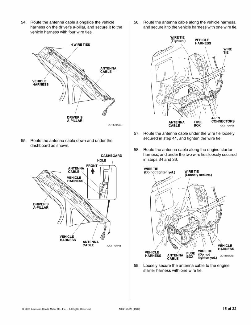
54. Route the antenna cable alongside the vehicleharness on the driver’s a-pillar, and secure it to thevehicle harness with four wire ties.
QC11704AB
ANTENNACABLE
4 WIRE TIES
VEHICLEHARNESS
DRIVER’SA-PILLAR
55. Route the antenna cable down and under thedashboard as shown.
QC11705AB
DRIVER’SA-PILLAR
VEHICLEHARNESS ANTENNA
CABLE
VEHICLEHARNESS
ANTENNACABLE
FRONT
HOLEDASHBOARD
© 2015 American Honda Motor Co., Inc. – All Rights Reserved. AII02125-2
56. Route the antenna cable along the vehicle harness,and secure it to the vehicle harness with one wire tie.
QC11706AB
VEHICLEHARNESS
FUSEBOX
4-PINCONNECTORS
WIRETIE
WIRE TIE(Tighten.)
ANTENNACABLE
57. Route the antenna cable under the wire tie looselysecured in step 41, and tighten the wire tie.
58. Route the antenna cable along the engine starterharness, and under the two wire ties loosely securedin steps 34 and 36.
QC11801ABFUSEBOX
VEHICLEHARNESS
WIRE TIE(Do nottighten yet.)
ANTENNACABLE
WIRE TIE(Loosely secure.)
VEHICLEHARNESS
WIRE TIE(Do not tighten yet.)
59. Loosely secure the antenna cable to the enginestarter harness with one wire tie.
0 (1507) 15 of 22

60. Route the antenna cable along the engine starterharness, and under the two wire ties loosely securedin step 33.
QC11802AB
FUSEBOX
VEHICLEHARNESS
ANTENNACABLE
2 WIRE TIES(Do not tighten yet.)
ENGINESTARTERHARNESS
16 of 22 AII02125-2
Installing the Control Unit
61. Under the dash near the fuse box, locate the parkingbrake bracket flange nut. Remove the parking brakebracket flange nut.
QC11803BB
PARKINGBRAKEBRACKET
VEHICLEPANELPARKING
BRAKEBRACKET
CONTROLUNITBRACKET
PARKING BRAKEBRACKETFLANGE NUT
CONTROLUNITBRACKET
PARKINGBRAKEBRACKETFLANGE NUT
PARKINGBRAKEBRACKET
Align.
CONTROL UNITBRACKET
NOTCH
FELT-TIPPEN
MARK
62. Install the control unit bracket on top of the parkingbrake bracket and align the notch in the control unitbracket with the edge of the parking brake bracket.Reinstall the parking brake bracket flange nut, andtorque it to 18.7 to 24.5 N·m (13.8 to 18.1 lbf·ft).
63. Using a felt-tip pen, mark the parking brake bracketflange nut and control unit bracket as shown.
0 (1507) © 2015 American Honda Motor Co., Inc. – All Rights Reserved.

64. Plug the antenna cable connector, and the enginestarter harness 28-pin connector into the controlunit.
QC11804AB
CONTROL UNIT
ANTENNACABLECONNECTOR
ENGINE STARTERHARNESS 28-PINCONNECTOR
65. Install the control unit to the control unit bracket.
QC11805AB
CONTROLUNIT
CONTROL UNITBRACKET
FUSECASE CLIP
CONTROL UNITBRACKET
HOLE
CONTROLUNIT
FUSECASE
CONTROLUNITBRACKETFUSE
BOX
66. Attach the clip on the engine starter harness fusecase to the hole in the control unit bracket.
© 2015 American Honda Motor Co., Inc. – All Rights Reserved. AII02125-2
67. Bundle up the excess antenna cable, and secure it tothe vehicle harness and engine starter harness withtwo wire ties loosely secured in steps 58 and 59.Tighten the lower three wire ties loosely secured insteps 58 and 60.
QC11806AB
20 mm (0.8 in.)or above.
ANTENNA CABLE(Bundle up the excess.)
2 WIRETIES
ENGINE STARTERHARNESS
VEHICLEHARNESS
68. Using isopropyl alcohol on a shop towel, thoroughlyclean the hood where the caution label will attach.
021515AY
ADHESIVEBACKING(Remove.)
CAUTIONLABEL
Clean withisopropyl alcohol.HOOD
69. Remove the adhesive backing from the caution label,and attach the caution label to the hood in the areashown.
0 (1507) 17 of 22

70. Check that all wire harness and cable are routedproperly and all connectors are plugged in.
71. Check the marks (step 64) of the parking brakebracket flange nut and control unit bracket and makesure that the parking brake bracket flange nut is notloose.
72. Check the overlap between the headliner and thedriver’s A-pillar trim. Refer to the Service Manual. Ifnecessary, adjust the overlap.
73. Reinstall all removed parts. Take care not to pinchthe airbag with the clip during reinstallation of theA-pillar trim. Do not push excessively on the A-pillartrim.
74. Reconnect the negative cable to the battery.
75. Check the operation of the headlights and wipers.
76. Reset the clock on vehicle without navigation.
77. Perform the “REMOTE ENGINE STARTERREGISTRATION” and the “FUNCTION CHECK”.
18 of 22 AII02125-2
REMOTE ENGINE STARTER REGISTRATION
NOTE: Register after making sure the HDS has beenupgraded to the latest version as described in the ServiceNews.
1. Acquire the PCM Code from the Interactive Network.
QC31909AC
CAR ICON
2. Connect the HDS/MVCI tester to the OBD II data linkconnector, then turn the ignition switch to the on (II)position.
3. Start the HDS, and click the car icon.
4. Input the VIN and other required information into theHDS, then click the check button.
QB32102BH
Input the VIN and otherrequired information. CHECK BUTTON
0 (1507) © 2015 American Honda Motor Co., Inc. – All Rights Reserved.

5. Select Honda Systems, then click the check button.
QB32103AH
Select“Honda Systems.”
CHECK BUTTON
6. Select R/C ENG STARTER and click the checkbutton.
QB32104AH
Select“R/C ENG STARTER.”
CHECK BUTTON
© 2015 American Honda Motor Co., Inc. – All Rights Reserved. AII02125-2
7. Select REGISTER REMOTE CONTROL ENGINESTARTER UNIT, then click the check button.
QB32105BH
Select“REGISTER REMOTECONTROL ENGINESTARTER UNIT.”
CHECK BUTTON
8. The following message will display: Obtain PCM-code (IMMOBILIZER PCM CODE) from iN. Thisvehicle’s VIN will be required to obtain thepassword. (USA) Click the check button.
QB32106AH
“Obtain PCM-code”message.
CHECK BUTTON
0 (1507) 19 of 22
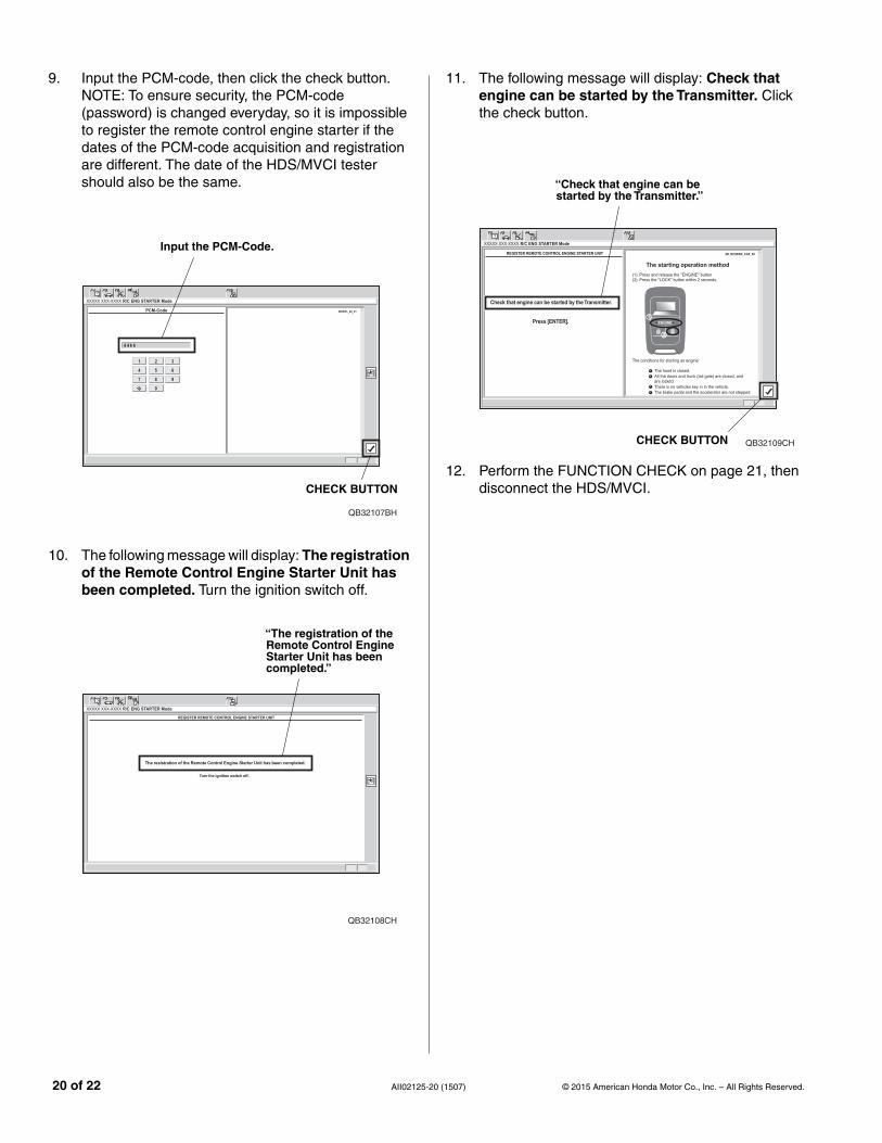
9. Input the PCM-code, then click the check button.NOTE: To ensure security, the PCM-code(password) is changed everyday, so it is impossibleto register the remote control engine starter if thedates of the PCM-code acquisition and registrationare different. The date of the HDS/MVCI testershould also be the same.
QB32107BH
Input the PCM-Code.
CHECK BUTTON
10. The following message will display: The registrationof the Remote Control Engine Starter Unit hasbeen completed. Turn the ignition switch off.
QB32108CH
“The registration of theRemote Control EngineStarter Unit has beencompleted.”
20 of 22 AII02125-2
11. The following message will display: Check thatengine can be started by the Transmitter. Clickthe check button.
QB32109CH
“Check that engine can bestarted by the Transmitter.”
CHECK BUTTON
12. Perform the FUNCTION CHECK on page 21, thendisconnect the HDS/MVCI.
0 (1507) © 2015 American Honda Motor Co., Inc. – All Rights Reserved.

FUNCTION CHECK
Operating Conditions
• The hood is closed
• The shift lever is in park
• Turn the ignition switch off and the key is outside the vehicle
• All doors and tailgate closed and locked
Inspection
1. Press the engine/command button on the transmitter and release, within 2 seconds, press the lock/start button onthe transmitter.
The engine should start if all operating conditions are met.
Does the engine start?
Yes - Operation is normal.
No:
• Make sure all “Operating Conditions” are met.
• Check the engine starter harness connections.
• Connect the HDS/MVCI and check for an indicated failure.
(Refer to the appropriate Service Manual for details.)
QB62902AB
ENGINE/COMMANDBUTTON
UNLOCK/STOPBUTTON
RECEPTIONINDICATOR
CHECKINGINDICATOR
ENGINE STARTOPERATION
Blinking
ENGINERUNNINGINDICATOR
REMAININGIDLING TIME
LOCK/STARTBUTTON
2. Press the engine/command button on the transmitterand release, within 2 seconds, press the unlock/stopbutton. The engine should stop.
Does the engine stop?
Yes - Operation is normal.
No - Check the engine starter harness connections.
3. After the engine has stopped, start the engine again,and check that the engine stops after each of thefollowing conditions:
NOTE: After each test the ignition key must be cycled, or thedriver’s door must be opened and closed.
• Move the shift lever out of the P position.
• Unlock or open the doors or the tailgate.
• Open the hood.
• Insert the key in the ignition.
• Press the engine start/stop button.
• Press on the brake pedal.
Does the engine stop after each of these tests?
Yes - Operation is normal.
No - Check the engine starter harness connections.
4. Check that the power windows and the moonroof do not function, and the shift lever does not move to any positionwhen the engine is started with the transmitter.
5. Check that the engine does not start under “Operating Conditions” with the key left inside the vehicle.
6. Start the engine again, press the engine/command button on the transmitter two times, and check the vehiclecondition on the display.
© 2015 American Honda Motor Co., Inc. – All Rights Reserved. AII02125-20 (1507) 21 of 22

7. Check the operation of the transmitter when the vehicle is 120 m (400 ft.) away and in direct sight.
8. Press the unlock/stop button on the transmitter and verify that the doors unlock. Press the lock/start button, andverify that the doors lock.
9. Check that the engine can start by the vehicle key and that the wiper and the headlight can be operated normally.
22 of 22 AII02125-20 (1507) © 2015 American Honda Motor Co., Inc. – All Rights Reserved.