installation/operating manual - pumps, valves and service … · installation/operating manual....
TRANSCRIPT
4073
.8/0
2-E
N
KSB Aktiengesellschaft
202H12GM 1450R031
*MG21H202*
PumpDrive R (KSB202)
Motor-independent Frequency Converterfor centrifugal pumps
Operating range 0.25-90 kW
Installation/Operating Manual

NOTICEUse the KSB202 frequency converter with synchronousreluctance motors (SynRM) only in pump and fanapplications.
NOTICEDo not operate the KSB202 frequency converter withsynchronous reluctance motors (SynRM) above 200 rpmwithout coupling of a load! For checking the sense ofrotation, use the designated functionchapter 5.5 Checking Motor Rotation.
MG21H202 4073.8/02-EN All rights reserved.

4073.8/02-EN All rights reserved. MG21H202

Contents
1 Introduction 4
1.1 Purpose of the Operating Instructions 4
1.2 Additional Resources 4
1.3 Document and Software Version 4
1.4 Product Overview 4
1.5 Approvals and Certifications 8
1.6 Disposal 8
2 Safety 9
2.1 Safety Symbols 9
2.2 Qualified Personnel 9
2.3 Safety Precautions 9
3 Mechanical Installation 11
3.1 Unpacking 11
3.2 Installation Environments 11
3.3 Mounting 11
4 Electrical Installation 13
4.1 Safety Instructions 13
4.2 EMC-compliant Installation 13
4.3 Grounding 13
4.4 Wiring Schematic 14
4.5 Access 16
4.6 Motor Connection 16
4.7 AC Mains Connection 17
4.8 Control Wiring 17
4.8.1 Control Terminal Types 17
4.8.2 Wiring to Control Terminals 19
4.8.3 Enabling Motor Operation (Terminal 27) 19
4.8.4 Voltage/Current Input Selection (Switches) 19
4.8.5 RS485 Serial Communication 20
4.9 Installation Check List 21
5 Commissioning 22
5.1 Safety Instructions 22
5.2 Applying Power 22
5.3 Local Control Panel Operation 22
5.3.1 Local Control Panel 22
5.3.2 GLCP Layout 23
Contents
MG21H202 4073.8/02-EN All rights reserved. 1

5.3.3 Parameter Settings 24
5.3.4 Uploading/Downloading Data to/from the LCP 24
5.3.5 Changing Parameter Settings 24
5.3.6 Restoring Default Settings 24
5.4 Basic Programming 25
5.4.1 Commissioning with SmartStart 25
5.4.2 Commissioning via [Main Menu] 25
5.4.3 Asynchronous Motor Set-up 26
5.4.4 PM Motor Setup in VVC+ 27
5.4.5 SynRM Motor Set-up with VVC+ 28
5.4.6 Automatic Energy Optimisation (AEO) 29
5.4.7 Automatic Motor Adaptation (AMA) 29
5.5 Checking Motor Rotation 29
5.6 Local-control Test 30
5.7 System Start-up 31
6 Application Set-up Examples 32
7 Maintenance, Diagnostics and Troubleshooting 36
7.1 Maintenance and Service 36
7.2 Status Messages 36
7.3 Warning and Alarm Types 38
7.4 List of Warnings and Alarms 39
7.5 Troubleshooting 46
8 Specifications 49
8.1 Electrical Data 49
8.1.1 Mains Supply 1x200–240 V AC 49
8.1.2 Mains Supply 3x200–240 V AC 50
8.1.3 Mains Supply 1x380–480 V AC 52
8.1.4 Mains Supply 3x380–480 V AC 53
8.1.5 Mains Supply 3x525–600 V AC 57
8.1.6 Mains Supply 3x525–690 V AC 61
8.2 Mains Supply 64
8.3 Motor Output and Motor Data 64
8.4 Ambient Conditions 65
8.5 Cable Specifications 65
8.6 Control Input/Output and Control Data 65
8.7 Connection Tightening Torques 68
8.8 Fuses and Circuit Breakers 69
8.9 Power Ratings, Weight, and Dimensions 76
Contents
2 4073.8/02-EN All rights reserved. MG21H202

9 Appendix 78
9.1 Symbols, Abbreviations, and Conventions 78
9.2 Parameter Menu Structure 78
Index 83
Contents
MG21H202 4073.8/02-EN All rights reserved. 3

1 Introduction
1.1 Purpose of the Operating Instructions
These operating instructions provide information for safeinstallation and commissioning of the frequency converter.
The operating instructions are intended for use byqualified personnel.Read and follow the operating instructions to use thefrequency converter safely and professionally, and payparticular attention to the safety instructions and generalwarnings. Keep these operating instructions available withthe frequency converter at all times.
1.2 Additional Resources
Other resources are available to understand advancedfrequency converter functions and programming.
• The Programming Guide provides greater detail onworking with parameters and many applicationexamples.
• The Design Guide provides detailed informationabout capabilities and functionality to designmotor control systems.
• Instructions for operation with optionalequipment.
1.3 Document and Software Version
This manual is regularly reviewed and updated. Allsuggestions for improvement are welcome. Please sendsuggestions via email [email protected], including areference to the document version.
Table 1.1 shows the document version and thecorresponding software version.
Edition Remarks Software version
MG21H2xx Replaces MG21H1xx 2.x
Table 1.1 Document and Software Version
1.4 Product Overview
1.4.1 Intended Use
The frequency converter is an electronic motor controllerintended for:
• Regulation of motor speed in response to systemfeedback or to remote commands from externalcontrollers. A power drive system consists of thefrequency converter, the motor, and equipmentdriven by the motor.
• System and motor status surveillance.
Depending on configuration, the frequency converter canbe used in standalone applications or form part of a largerappliance or installation.
The frequency converter is allowed for use in residential,industrial, and commercial environments in accordancewith local laws, standards, and emission limits as describedin the design guide.
Single phase frequency converters (S2 and S4) installedin the EUThe following limitations apply:
• Units with an input current below 16 A and aninput power above 1 kW are only intended forprofessional use in trades, professions, orindustries and not for sale to the general public.
• Designated application areas are public pools,public water supplies, agriculture, commercialbuildings, and industries. All other single phaseunits are only intended for use in private low-voltage systems interfacing with public supplyonly at a medium or high voltage level.
• Operators of private systems must ensure thatthe EMC environment complies with IEC610000-3-6 and/or the contractual agreements.
NOTICEIn a residential environment, this product can causeradio interference, in which case supplementarymitigation measures may be required.
Foreseeable misuseDo not use the frequency converter in applications, whichare non-compliant with specified operating conditions andenvironments. Ensure compliance with the conditionsspecified in chapter 8 Specifications.
Introduction
4 4073.8/02-EN All rights reserved. MG21H202
11
1.4.2 Features
The KSB202 is designed for water and wastewaterapplications. The range of standard and optional featuresincludes:
• Cascade control.
• Dry run detection.
• End of curve detection.
• SmartStart.
• Motor alternation.
• Deragging.
• 2-step ramps.
• Flow Confirmation.
• Check valve protection.
• Safe Torque Off.
• Low flow detection.
• Pre/Post Lubrication.
• Pipe fill mode.
• Sleep mode.
• Real-time clock.
• User configurable info texts.
• Warnings and alarms.
• Password protection.
• Overload protection.
• Smart logic control.
• Dual Power rating (High/Normal Overload).
Introduction
MG21H202 4073.8/02-EN All rights reserved. 5
1 1

1.4.3 Exploded Views
1 Local control panel (LCP) 11 Relay 2 (04, 05, 06)
2 Cover 12 Lifting ring
3 RS485 serial bus connector 13 Mounting slot
4 Digital I/O and 24 V power supply 14 Grounding clamp (PE)
5 Analog I/O connector 15 Cable screen connector
6 Cable screen connector 16 Brake terminal (-81, +82)
7 USB connector 17 Load sharing terminal (DC bus) (-88, +89)
8 Serial bus terminal switch 18 Motor output terminals 96 (U), 97 (V), 98 (W)
9 Analog switches (A53), (A54) 19 Mains input terminals 91 (L1), 92 (L2), 93 (L3)
10 Relay 1 (01, 02, 03)
Illustration 1.1 Exploded View Enclosure Types B and C, IP55 and IP66
Introduction
6 4073.8/02-EN All rights reserved. MG21H202
11

1 Local control panel (LCP) 10 Motor output terminals 96 (U), 97 (V), 98 (W)
2 RS485 serial bus connector (+68, -69) 11 Relay 2 (01, 02, 03)
3 Analog I/O connector 12 Relay 1 (04, 05, 06)
4 LCP input plug 13 Brake (-81, +82) and load sharing (-88, +89) terminals
5 Analog switches (A53), (A54) 14 Mains input terminals 91 (L1), 92 (L2), 93 (L3)
6 Cable screen connector 15 USB connector
7 Decoupling plate 16 Serial bus terminal switch
8 Grounding clamp (PE) 17 Digital I/O and 24 V power supply
9 Screened cable grounding clamp and strain relief 18 Cover
Illustration 1.2 Exploded View Enclosure Type A, IP20
Introduction
MG21H202 4073.8/02-EN All rights reserved. 7
1 1

Illustration 1.3 is a block diagram of the internalcomponents of the frequency converter. See the table forIllustration 1.3 for their functions.
Area Title Functions
1 Mains input• 3-phase AC mains supply to the
frequency converter.
2 Rectifier
• The rectifier bridge converts the
AC input to DC current to supplyinverter power.
3 DC bus• Intermediate DC bus circuit
handles the DC current.
4 DC reactors
• Filter the intermediate DC circuit
voltage.
• Prove mains transient protection.
• Reduce RMS current.
• Raise the power factor reflectedback to the line.
• Reduce harmonics on the ACinput.
5 Capacitor bank
• Stores the DC power.
• Provides ride-through protectionfor short power losses.
6 Inverter
• Converts the DC into a controlledPWM AC waveform for acontrolled variable output to themotor.
7 Output to motor• Regulated 3-phase output power
to the motor.
8 Control circuitry
• Input power, internal processing,output, and motor current aremonitored to provide efficientoperation and control.
• User interface and externalcommands are monitored andperformed.
• Status output and control can beprovided.
Illustration 1.3 Frequency Converter Block Diagram
1.4.4 Enclosure Types and Power Ratings
For enclosure types and power ratings of the frequencyconverters, refer to chapter 8.9 Power Ratings, Weight, andDimensions.
1.5 Approvals and Certifications
More approvals and certifications are available. Contact thelocal KSB partner. Frequency converters of enclosure typeT7 (525–690 V) are UL certified for only 525–600 V.
The frequency converter complies with UL508C thermalmemory retention requirements. For more information,refer to the section Motor Thermal Protection in the VLT®
AQUA Drive FC 202 Design Guide.
For compliance with the European Agreement concerningInternational Carriage of Dangerous Goods by InlandWaterways (ADN), refer to ADN-compliant Installation in theproduct specific design guide.
1.6 Disposal
Do not dispose of equipment containingelectrical components together withdomestic waste.Collect it separately in accordance withlocal and currently valid legislation.
Introduction
8 4073.8/02-EN All rights reserved. MG21H202
11

2 Safety
2.1 Safety Symbols
The following symbols are used in this manual:
WARNINGIndicates a potentially hazardous situation that couldresult in death or serious injury.
CAUTIONIndicates a potentially hazardous situation that couldresult in minor or moderate injury. It can also be used toalert against unsafe practices.
NOTICEIndicates important information, including situations thatcan result in damage to equipment or property.
2.2 Qualified Personnel
Correct and reliable transport, storage, installation,operation, and maintenance are required for the trouble-free and safe operation of the frequency converter. Onlyqualified personnel are allowed to install or operate thisequipment.
Qualified personnel are defined as trained staff, who areauthorised to install, commission, and maintain equipment,systems, and circuits in accordance with pertinent laws andregulations. Additionally, the qualified personnel must befamiliar with the instructions and safety measuresdescribed in these operating instructions.
2.3 Safety Precautions
WARNINGHIGH VOLTAGEFrequency converters contain high voltage whenconnected to AC mains input, DC supply, or load sharing.Failure to perform installation, start-up, and maintenanceby qualified personnel can result in death or seriousinjury.
• Installation, start-up, and maintenance must beperformed by qualified personnel only.
WARNINGUNINTENDED STARTWhen the frequency converter is connected to AC mains,DC supply, or load sharing, the motor may start at anytime. Unintended start during programming, service, orrepair work can result in death, serious injury, orproperty damage. The motor can start via an externalswitch, a serial bus command, an input reference signalfrom the LCP, or after a cleared fault condition.To prevent unintended motor start:
• Disconnect the frequency converter from themains.
• Press [Off/Reset] on the LCP beforeprogramming parameters.
• Fully wire and assembly the frequencyconverter, motor, and any driven equipmentbefore connecting the frequency converter toAC mains, DC supply, or load sharing.
WARNINGDISCHARGE TIMEThe frequency converter contains DC-link capacitors,which can remain charged even when the frequencyconverter is not powered. Failure to wait the specifiedtime after power has been removed before performingservice or repair work, could result in death or seriousinjury.
1. Stop the motor.
2. Disconnect the AC mains, permanent magnettype motors, and remote DC-link powersupplies, including battery back-ups, UPS, andDC-link connections to other frequencyconverters.
3. Wait for the capacitors to discharge fully beforeperforming any service or repair work. Theduration of waiting time is specified in Table 2.1.
Voltage [V]Minimum waiting time (minutes)
4 7 15
200–240 0.25–3.7 kW 5.5–45 kW
380–480 0.37–7.5 kW 11–90 kW
525–600 0.75–7.5 kW 11–90 kW
525–690 1.1–7.5 kW 11–90 kW
High voltage may be present even when the warning LEDindicator lights are off.
Table 2.1 Discharge Time
Safety
MG21H202 4073.8/02-EN All rights reserved. 9
2 2

WARNINGLEAKAGE CURRENT HAZARDLeakage currents exceed 3.5 mA. Failure to ground thefrequency converter properly can result in death orserious injury.
• Ensure the correct grounding of the equipmentby a certified electrical installer.
WARNINGEQUIPMENT HAZARDContact with rotating shafts and electrical equipmentcan result in death or serious injury.
• Ensure that only trained and qualified personnelperform installation, start-up, and maintenance.
• Ensure that electrical work conforms to nationaland local electrical codes.
• Follow the procedures in this manual.
WARNINGUNINTENDED MOTOR ROTATIONWINDMILLINGUnintended rotation of permanent magnet motorscreates voltage and can charge the unit, resulting indeath, serious injury, or equipment damage.
• Ensure that permanent magnet motors areblocked to prevent unintended rotation.
CAUTIONINTERNAL FAILURE HAZARDAn internal failure in the frequency converter can resultin serious injury, when the frequency converter is notproperly closed.
• Ensure that all safety covers are in place andsecurely fastened before applying power.
Safety
10 4073.8/02-EN All rights reserved. MG21H202
22

3 Mechanical Installation
3.1 Unpacking
3.1.1 Items Supplied
Items supplied may vary according to product configu-ration.
• Make sure the items supplied and the informationon the nameplate correspond to the order confir-mation.
• Check the packaging and the frequency convertervisually for damage caused by inappropriatehandling during shipment. File any claim fordamage with the carrier. Retain damaged partsfor clarification.
1 Type code
2 Order number
3 Serial number
4 Power rating
5Input voltage, frequency and current (at low/highvoltages)
6Output voltage, frequency and current (at low/highvoltages)
7 Enclosure type and IP rating
8 Maximum ambient temperature
9 Certifications
10 Discharge time (Warning)
Illustration 3.1 Product Nameplate (Example)
NOTICEDo not remove the nameplate from the frequencyconverter. Removing the nameplate voids the warranty.
3.1.2 Storage
Ensure that the requirements for storage are fulfilled. Referto chapter 8.4 Ambient Conditions for further details.
3.2 Installation Environments
NOTICEIn environments with airborne liquids, particles, orcorrosive gases, ensure that the IP/type rating of theequipment matches the installation environment. Failureto meet requirements for ambient conditions can reducethe lifetime of the frequency converter. Ensure thatrequirements for air humidity, temperature, and altitudeare met.
Vibration and shockThe frequency converter complies with requirements forunits mounted on the walls and floors of productionpremises, as well as in panels bolted to walls or floors.
For detailed ambient conditions specifications, refer to chapter 8.4 Ambient Conditions.
3.3 Mounting
NOTICEImproper mounting can result in overheating andreduced performance.
Cooling
• Ensure that top and bottom clearance for aircooling is provided. See Illustration 3.2 forclearance requirements.
Mechanical Installation
MG21H202 4073.8/02-EN All rights reserved. 11
3 3
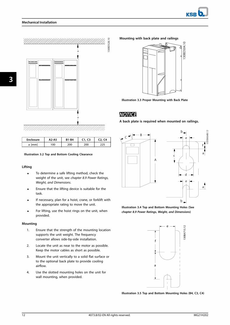
Enclosure A2-A5 B1-B4 C1, C3 C2, C4
a [mm] 100 200 200 225
Illustration 3.2 Top and Bottom Cooling Clearance
Lifting
• To determine a safe lifting method, check theweight of the unit, see chapter 8.9 Power Ratings,Weight, and Dimensions.
• Ensure that the lifting device is suitable for thetask.
• If necessary, plan for a hoist, crane, or forklift withthe appropriate rating to move the unit.
• For lifting, use the hoist rings on the unit, whenprovided.
Mounting
1. Ensure that the strength of the mounting locationsupports the unit weight. The frequencyconverter allows side-by-side installation.
2. Locate the unit as near to the motor as possible.Keep the motor cables as short as possible.
3. Mount the unit vertically to a solid flat surface orto the optional back plate to provide coolingairflow.
4. Use the slotted mounting holes on the unit forwall mounting, when provided.
Mounting with back plate and railings
Illustration 3.3 Proper Mounting with Back Plate
NOTICEA back plate is required when mounted on railings.
Illustration 3.4 Top and Bottom Mounting Holes (Seechapter 8.9 Power Ratings, Weight, and Dimensions)
Illustration 3.5 Top and Bottom Mounting Holes (B4, C3, C4)
Mechanical Installation
12 4073.8/02-EN All rights reserved. MG21H202
33
4 Electrical Installation
4.1 Safety Instructions
See chapter 2 Safety for general safety instructions.
WARNINGINDUCED VOLTAGEInduced voltage from output motor cables that runtogether can charge equipment capacitors, even with theequipment turned off and locked out. Failure to runoutput motor cables separately or use screened cablescould result in death or serious injury.
• Run output motor cables separately, or
• Use screened cables.
CAUTIONSHOCK HAZARDThe frequency converter can cause a DC current in thePE conductor. Failure to follow the recommendationmeans that the RCD may not provide the intendedprotection.
• When a residual current-operated protectivedevice (RCD) is used for protection againstelectrical shock, only an RCD of Type B ispermitted on the supply side.
Overcurrent protection
• Extra protective equipment, such as short-circuitprotection or motor thermal protection betweenfrequency converter and motor, is required forapplications with multiple motors.
• Input fusing is required to provide short-circuitand overcurrent protection. If not factory-supplied, the installer must provide fuses. Seemaximum fuse ratings in chapter 8.8 Fuses andCircuit Breakers.
Wire type and ratings
• All wiring must comply with local and nationalregulations regarding cross-section and ambienttemperature requirements.
• Power connection wire recommendation:Minimum 75 °C rated copper wire.
See chapter 8.1 Electrical Data and chapter 8.5 Cable Specifi-cations for recommended wire sizes and types.
4.2 EMC-compliant Installation
To obtain an EMC-compliant installation, follow theinstructions provided in chapter 4.3 Grounding, chapter 4.4 Wiring Schematic,chapter 4.6 Motor Connection,and chapter 4.8 Control Wiring.
4.3 Grounding
WARNINGLEAKAGE CURRENT HAZARDLeakage currents exceed 3.5 mA. Failure to ground thefrequency converter properly could result in death orserious injury.
• Ensure the correct grounding of the equipmentby a certified electrical installer.
For electrical safety
• Ground the frequency converter in accordancewith applicable standards and directives.
• Use a dedicated ground wire for input power,motor power, and control wiring.
• Do not ground one frequency converter toanother in a daisy chain fashion.
• Keep the ground wire connections as short aspossible.
• Follow motor manufacturer wiring requirements.
• Minimum cable cross-section: 10 mm2 (or 2 ratedground wires terminated separately).
For EMC-compliant installation
• Establish electrical contact between the cablescreen and the frequency converter enclosure byusing metal cable glands or by using the clampsprovided on the equipment (see chapter 4.6 MotorConnection).
• Use high-strand wire to reduce electricalinterference.
• Do not use pigtails.
NOTICEPOTENTIAL EQUALISATIONRisk of electrical interference, when the ground potentialbetween the frequency converter and the control systemis different. Install equalising cables between the systemcomponents. Recommended cable cross-section: 16 mm2.
Electrical Installation
MG21H202 4073.8/02-EN All rights reserved. 13
4 4

4.4 Wiring Schematic
Illustration 4.1 Basic Wiring Schematic
A=Analog, D=Digital*Terminal 37 (optional) is used for Safe Torque Off. For Safe Torque Off installation instructions, refer to the VLT® FrequencyConverters - Safe Torque Off Operating Instructions.**Do not connect cable screen.
Electrical Installation
14 4073.8/02-EN All rights reserved. MG21H202
44

1 PLC 6 Cable gland
2 Frequency converter 7 Motor, 3-phase and PE
3 Output contactor 8 Mains, 3-phase and reinforced PE
4 Grounding rail (PE) 9 Control wiring
5 Cable insulation (stripped) 10 Equalising min. 16 mm2 (0.025 in2)
Illustration 4.2 EMC-compliant Electrical Connection
NOTICEEMC INTERFERENCEUse screened cables for motor and control wiring and separate cables for input power, motor wiring, and control wiring.Failure to isolate power, motor, and control cables can result in unintended behaviour or reduced performance.Minimum clearance requirement between power, motor and control cables is 200 mm (7.9 in).
Electrical Installation
MG21H202 4073.8/02-EN All rights reserved. 15
4 4

4.5 Access
• Remove the cover with a screw driver (SeeIllustration 4.3) or by loosening the attachingscrews (See Illustration 4.4).
Illustration 4.3 Access to Wiring for IP20 and IP21 Enclosures
Illustration 4.4 Access to Wiring for IP55 and IP66 Enclosures
Tighten the cover screws using the tightening torquesspecified in Table 4.1.
Enclosure IP55 IP66
A4/A5 2 2
B1/B2 2.2 2.2
C1/C2 2.2 2.2
No screws to tighten for A2/A3/B3/B4/C3/C4.
Table 4.1 Tightening Torques for Covers [Nm]
4.6 Motor Connection
WARNINGINDUCED VOLTAGEInduced voltage from output motor cables that runtogether can charge equipment capacitors, even with theequipment turned off and locked out. Failure to runoutput motor cables separately or use screened cablescould result in death or serious injury.
• Run output motor cables separately, or
• Use screened cables.
• Comply with local and national electrical codesfor cable sizes. For maximum wire sizes see chapter 8.1 Electrical Data.
• Follow motor manufacturer wiring requirements.
• Motor wiring knockouts or access panels areprovided at the base of IP21 (NEMA1/12) andhigher units.
• Do not wire a starting or pole-changing device(e.g. Dahlander motor or slip ring inductionmotor) between the frequency converter and themotor.
Procedure
1. Strip a section of the outer cable insulation.
2. Position the stripped wire under the cable clampto establish mechanical fixation and electricalcontact between the cable screen and ground.
3. Connect the ground wire to the nearestgrounding terminal in accordance with thegrounding instructions provided in chapter 4.3 Grounding, see Illustration 4.5.
4. Connect the 3-phase motor wiring to terminals96 (U), 97 (V), and 98 (W), see Illustration 4.5.
5. Tighten the terminals in accordance with theinformation provided in chapter 8.7 ConnectionTightening Torques.
Electrical Installation
16 4073.8/02-EN All rights reserved. MG21H202
44
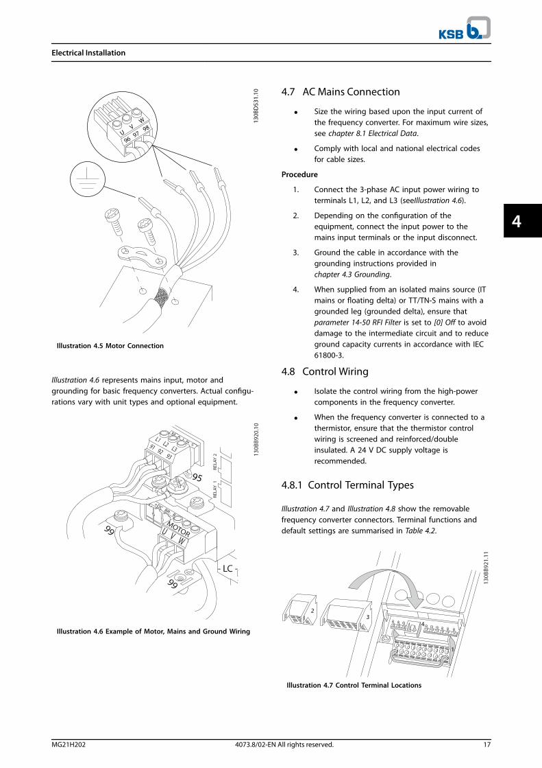
Illustration 4.5 Motor Connection
Illustration 4.6 represents mains input, motor andgrounding for basic frequency converters. Actual configu-rations vary with unit types and optional equipment.
Illustration 4.6 Example of Motor, Mains and Ground Wiring
4.7 AC Mains Connection
• Size the wiring based upon the input current ofthe frequency converter. For maximum wire sizes,see chapter 8.1 Electrical Data.
• Comply with local and national electrical codesfor cable sizes.
Procedure
1. Connect the 3-phase AC input power wiring toterminals L1, L2, and L3 (seeIllustration 4.6).
2. Depending on the configuration of theequipment, connect the input power to themains input terminals or the input disconnect.
3. Ground the cable in accordance with thegrounding instructions provided in chapter 4.3 Grounding.
4. When supplied from an isolated mains source (ITmains or floating delta) or TT/TN-S mains with agrounded leg (grounded delta), ensure thatparameter 14-50 RFI Filter is set to [0] Off to avoiddamage to the intermediate circuit and to reduceground capacity currents in accordance with IEC61800-3.
4.8 Control Wiring
• Isolate the control wiring from the high-powercomponents in the frequency converter.
• When the frequency converter is connected to athermistor, ensure that the thermistor controlwiring is screened and reinforced/doubleinsulated. A 24 V DC supply voltage isrecommended.
4.8.1 Control Terminal Types
Illustration 4.7 and Illustration 4.8 show the removablefrequency converter connectors. Terminal functions anddefault settings are summarised in Table 4.2.
Illustration 4.7 Control Terminal Locations
Electrical Installation
MG21H202 4073.8/02-EN All rights reserved. 17
4 4

Illustration 4.8 Terminal Numbers
• Connector 1 provides:
- 4 programmable digital inputs terminals.
- 2 additional digital terminalsprogrammable as either input or output.
- 24 V DC terminal supply voltage.
- Optional customer supplied 24 V DCvoltage.
• Connector 2 terminals (+)68 and (-)69 are for anRS485 serial communication connection.
• Connector 3 provides:
- 2 analog inputs.
- 1 analog output.
- 10 V DC supply voltage.
- Commons for the inputs and output.
• Connector 4 is a USB port available for use withthe MCT 10 Set-up Software.
Terminal description
Terminal ParameterDefaultsetting Description
Digital Inputs/Outputs
12, 13 - +24 V DC 24 V DC supply voltage
for digital inputs andexternal transducers.Maximum output
current 200 mA for all24 V loads.
18 5-10 [8] Start
Digital inputs.
19 5-11 [0] Nooperation
32 5-14 [0] Nooperation
33 5-15 [0] No
operation
27 5-12 [2] Coast
inverseFor digital input oroutput. Default settingis input.29 5-13 [14] JOG
20 - Common for digitalinputs and 0 V
potential for 24 Vsupply.
Terminal description
Terminal ParameterDefaultsetting Description
37 - Safe Torque
Off (STO)
Safe input (optional).
Used for STO.
Analog Inputs/Outputs
39 -
Common for analogoutput
42 6-50 Speed 0 -High Limit
Programmable analogoutput. 0–20 mA or 4–20 mA at a maximum
of 500 Ω50 - +10 V DC 10 V DC analog supply
voltage for potenti-ometer or thermistor.15 mA maximum
53 6-1 Reference Analog input. Forvoltage or current.Switches A53 and A54select mA or V.
54 6-2 Feedback
55 -
Common for analoginput
Serial Communication
61 - Integrated RC-Filter for
cable screen. ONLY forconnecting the screenin the event of EMC
problems.
68 (+) 8-3 RS485 Interface. Acontrol card switch isprovided fortermination resistance.
69 (-) 8-3
Relays
01, 02, 03 5-40 [0] [9] Alarm Form C relay output.For AC or DC voltageand resistive orinductive loads.
04, 05, 06 5-40 [1] [5] Running
Table 4.2 Terminal Description
Additional terminals:
• 2 form C relay outputs. Location of the outputsdepends on frequency converter configuration.
• Terminals located on built-in optional equipment.See the manual provided with the equipmentoption.
Electrical Installation
18 4073.8/02-EN All rights reserved. MG21H202
44

4.8.2 Wiring to Control Terminals
Control terminal connectors can be unplugged from thefrequency converter for ease of installation, as shown inIllustration 4.9.
NOTICEKeep control wires as short as possible and separatefrom high power cables to minimise interference.
1. Open the contact by inserting a small screwdriverinto the slot above the contact and push thescrewdriver slightly upwards.
Illustration 4.9 Connecting Control Wires
2. Insert the bare control wire into the contact.
3. Remove the screwdriver to fasten the control wireinto the contact.
4. Ensure that the contact is firmly established andnot loose. Loose control wiring can be the sourceof equipment faults or less than optimaloperation.
See chapter 8.5 Cable Specifications for control terminalwiring sizes and chapter 6 Application Set-up Examples fortypical control wiring connections.
4.8.3 Enabling Motor Operation(Terminal 27)
A jumper wire is required between terminal 12 (or 13) andterminal 27 for the frequency converter to operate whenusing factory default programming values.
• Digital input terminal 27 is designed to receive 24V DC external interlock command.
• When no interlock device is used, wire a jumperbetween control terminal 12 (recommended) or13 to terminal 27. The jumper provides aninternal 24 V signal on terminal 27.
• When the status line at the bottom of the LCPreads AUTO REMOTE COAST, it indicates that theunit is ready to operate but is missing an inputsignal on terminal 27.
• When factory installed optional equipment iswired to terminal 27, do not remove that wiring.
4.8.4 Voltage/Current Input Selection(Switches)
The analog input terminals 53 and 54 allow setting ofinput signal to voltage (0–10 V) or current (0/4–20 mA).
Default parameter setting:• Terminal 53: Speed reference signal in open loop
(see parameter 16-61 Terminal 53 Switch Setting).
• Terminal 54: Feedback signal in closed loop (seeparameter 16-63 Terminal 54 Switch Setting).
NOTICEDisconnect power to the frequency converter beforechanging switch positions.
1. Remove the LCP (local control panel) (seeIllustration 4.10).
2. Remove any optional equipment covering theswitches.
3. Set switches A53 and A54 to select the signaltype. U selects voltage, I selects current.
Illustration 4.10 Location of Terminal 53 and 54 Switches
Electrical Installation
MG21H202 4073.8/02-EN All rights reserved. 19
4 4

To run STO, additional wiring for the frequency converter isrequired. Refer to Safe Torque Off Operating Instructions forfurther information.
4.8.5 RS485 Serial Communication
Connect RS485 serial communication wiring to terminals(+)68 and (-)69.
• Use screened serial communication cable(recommended).
• See chapter 4.3 Grounding for proper grounding.
Illustration 4.11 Serial Communication Wiring Diagram
For basic serial communication set-up, select the following:
1. Protocol type in parameter 8-30 Protocol.
2. Frequency converter address inparameter 8-31 Address.
3. Baud rate in parameter 8-32 Baud Rate.
• 2 communication protocols are internal to thefrequency converter.
KSB FC
Modbus RTU
• Functions can be programmed remotely usingthe protocol software and RS485 connection or inparameter group 8-** Communications andOptions.
• Selecting a specific communication protocolchanges various default parameter settings tomatch that protocol’s specifications and makesadditional protocol-specific parameters available.
• Option cards for the frequency converter areavailable to provide additional communicationprotocols. See the option card documentation forinstallation and operation instructions.
Electrical Installation
20 4073.8/02-EN All rights reserved. MG21H202
44

4.9 Installation Check List
Before completing installation of the unit, inspect the entire installation as detailed in Table 4.3. Check and mark the itemswhen completed.
Inspect for Description Auxiliary equipment • Look for auxiliary equipment, switches, disconnects, or input fuses/circuit breakers, residing on the input
power side of the frequency converter, or output side to the motor. Ensure that they are ready for full-speed operation.
• Check the function and installation of any sensors used for feedback to the frequency converter.
• Remove any power factor correction caps on the motor.
• Adjust any power factor correction caps on the mains side and ensure that they are dampened.
Cable routing • Ensure that the motor wiring and control wiring are separated, screened, or in 3 separate metallic conduitsfor high-frequency interference isolation.
Control wiring • Check for broken or damaged wires and loose connections.
• Check that the control wiring is isolated from power and motor wiring for noise immunity.
• Check the voltage source of the signals, if necessary.
The use of screened cable or twisted pair is recommended. Ensure that the screen is terminated correctly.
Cooling clearance • Ensure that the top and bottom clearance is adequate to ensure proper air flow for cooling, see
chapter 3.3 Mounting.
Ambient conditions • Check that requirements for ambient conditions are met.
Fusing and circuit
breakers• Check for proper fusing or circuit breakers.
• Check that all fuses are inserted firmly and are in operational condition, and that all circuit breakers are inthe open position.
Grounding • Check for sufficient ground connections and ensure that those connections are tight and free of oxidation.
• Grounding to conduit, or mounting the back panel to a metal surface, is not a suitable grounding.
Input and outputpower wiring
• Check for loose connections.
• Check that the motor and mains cables are in separate conduit or separated screened cables.
Panel interior • Inspect that the unit interior is free of dirt, metal chips, moisture, and corrosion.
• Check that the unit is mounted on an unpainted, metal surface.
Switches • Ensure that all switch and disconnect settings are in the proper positions.
Vibration • Check that the unit is mounted solidly, or that shock mounts are used, as necessary.
• Check for an unusual amount of vibration.
Table 4.3 Installation Check List
CAUTIONPOTENTIAL HAZARD IN THE EVENT OF INTERNAL FAILURERisk of personal injury if the frequency converter is not properly closed.
• Before applying power, ensure that all safety covers are in place and securely fastened.
Electrical Installation
MG21H202 4073.8/02-EN All rights reserved. 21
4 4
5 Commissioning
5.1 Safety Instructions
See chapter 2 Safety for general safety instructions.
WARNINGHIGH VOLTAGEFrequency converters contain high voltage whenconnected to AC mains input power. Failure to performinstallation, start-up, and maintenance by qualifiedpersonnel could result in death or serious injury.
• Installation, start-up, and maintenance must beperformed by qualified personnel only.
Before applying power:1. Close the cover properly.
2. Check that all cable glands are firmly tightened.
3. Ensure that input power to the unit is OFF andlocked out. Do not rely on the frequencyconverter disconnect switches for input powerisolation.
4. Verify that there is no voltage on input terminalsL1 (91), L2 (92), and L3 (93), phase-to-phase andphase-to-ground.
5. Verify that there is no voltage on outputterminals 96 (U), 97 (V), and 98 (W), phase-to-phase and phase-to-ground.
6. Confirm continuity of the motor by measuring Ωvalues on U-V (96-97), V-W (97-98), and W-U(98-96).
7. Check for proper grounding of the frequencyconverter as well as the motor.
8. Inspect the frequency converter for looseconnections on the terminals.
9. Confirm that the supply voltage matches thevoltage of the frequency converter and themotor.
5.2 Applying Power
Apply power to the frequency converter using thefollowing steps:
1. Confirm that the input voltage is balanced within3%. If not, correct the input voltage imbalancebefore proceeding. Repeat this procedure afterthe voltage correction.
2. Ensure that any optional equipment wiring,matches the installation application.
3. Ensure that all operator devices are in the OFFposition. Panel doors must be closed and coverssecurely fastened.
4. Apply power to the unit. DO NOT start thefrequency converter now. For units with adisconnect switch, turn it to the ON position toapply power to the frequency converter.
5.3 Local Control Panel Operation
5.3.1 Local Control Panel
The local control panel (LCP) is the combined display andkeypad on the front of the unit.
The LCP has several user functions:
• Start, stop, and control speed when in localcontrol.
• Display operational data, status, warnings andcautions.
• Programme frequency converter functions.
• Manually reset the frequency converter after afault when auto-reset is inactive.
An optional numeric LCP (NLCP) is also available. The NLCPoperates in a manner similar to the LCP. See the productrelevant programming guide for details on use of the NLCP.
NOTICEFor commissioning via PC, install the MCT 10 Set-upSoftware.
Commissioning
22 4073.8/02-EN All rights reserved. MG21H202
55

5.3.2 GLCP Layout
The GLCP is divided into 4 functional groups (seeIllustration 5.1).
A. Display area
B. Display menu keys
C. Navigation keys and indicator lights (LEDs)
D. Operation keys and reset
Illustration 5.1 Graphic Local Control Panel (GLCP)
A. Display areaThe display area is activated when the frequency converterreceives power from the mains voltage, a DC bus terminal,or an external 24 V DC supply.
The information displayed on the LCP can be customisedfor user application. Select options in the Quick MenuQ3-13 Display Settings.
Display Parameter number Default setting
1 0-20 Speed [RPM]
2 0-21 Motor Current
3 0-22 Power [kW]
4 0-23 Frequency
5 0-24 Reference [%]
Table 5.1 Legend to Illustration 5.1, Display Area
B. Display menu keysMenu keys are used for menu access for parameter set-up,toggling through status display modes during normaloperation, and viewing fault log data.
Key Function
6 Status Shows operational information.
7 Quick Menu Allows access to programming parameters
for initial set-up instructions and manydetailed application instructions.
8 Main Menu Allows access to all programming
parameters.
9 Alarm Log Displays a list of current warnings, the last10 alarms, and the maintenance log.
Table 5.2 Legend to Illustration 5.1, Display Menu Keys
C. Navigation keys and indicator lights (LEDs)Navigation keys are used for programming functions andmoving the display cursor. The navigation keys alsoprovide speed control in local operation. There are also 3frequency converter status indicator lights in this area.
Key Function
10 Back Reverts to the previous step or list in themenu structure.
11 Cancel Cancels the last change or command as longas the display mode has not changed.
12 Info Press for a definition of the function beingdisplayed.
13 Navigation
Keys
Use the 4 navigation keys to move between
items in the menu.
14 OK Use to access parameter groups or to enable
a selection.
Table 5.3 Legend to Illustration 5.1, Navigation Keys
Indicator Light Function
15 On Green The ON light activates when the
frequency converter receivespower from the mains voltage, aDC bus terminal, or an external 24
V supply.
16 Warn Yellow When warning conditions are met,the yellow WARN light comes onand text appears in the displayarea identifying the problem.
17 Alarm Red A fault condition causes the redalarm light to flash and an alarmtext is displayed.
Table 5.4 Legend to Illustration 5.1, Indicator Lights (LEDs)
Commissioning
MG21H202 4073.8/02-EN All rights reserved. 23
5 5

D. Operation keys and resetOperation keys are located at the bottom of the LCP.
Key Function
18 Hand On Starts the frequency converter in localcontrol.
• An external stop signal by control inputor serial communication overrides thelocal hand on.
19 Off Stops the motor but does not remove power
to the frequency converter.
20 Auto On Puts the system in remote operational mode.
• Responds to an external start commandby control terminals or serial communi-cation.
21 Reset Resets the frequency converter manuallyafter a fault has been cleared.
Table 5.5 Legend to Illustration 5.1, Operation Keys and Reset
NOTICEThe display contrast can be adjusted by pressing [Status]and the []/[] keys.
5.3.3 Parameter Settings
Establishing the correct programming for applicationsoften requires setting functions in several relatedparameters. Details for parameters are provided in chapter 9.2 Parameter Menu Structure.
Programming data is stored internally in the frequencyconverter.
• For back-up, upload data into the LCP memory.
• To download data to another frequencyconverter, connect the LCP to that unit anddownload the stored settings.
• Restoring factory default settings does notchange data stored in the LCP memory.
5.3.4 Uploading/Downloading Data to/fromthe LCP
1. Press [Off] to stop the motor before uploading ordownloading data.
2. Press [Main Menu] parameter 0-50 LCP Copy andpress [OK].
3. Select [1] All to LCP to upload data to the LCP orselect [2] All from LCP to download data from theLCP.
4. Press [OK]. A progress bar shows the uploading ordownloading progress.
5. Press [Hand On] or [Auto On] to return to normaloperation.
5.3.5 Changing Parameter Settings
Parameter settings can be accessed and changed from theQuick Menu or from the Main Menu. The Quick Menu onlygives access to a limited number of parameters.
1. Press [Quick Menu] or [Main Menu] on the LCP.
2. Press [] [] to browse through the parametergroups, press [OK] to select a parameter group.
3. Press [] [] to browse through the parameters,press [OK] to select a parameter.
4. Press [] [] to change the value of a parametersetting.
5. Press [] [] to shift digit when a decimalparameter is in the editing state.
6. Press [OK] to accept the change.
7. Press either [Back] twice to enter Status, or press[Main Menu] once to enter the Main Menu.
View changesQuick Menu Q5 - Changes Made lists all parameterschanged from default settings.
• The list only shows parameters, which have beenchanged in the current edit set-up.
• Parameters, which have been reset to defaultvalues, are not listed.
• The message Empty indicates that no parametershave been changed.
5.3.6 Restoring Default Settings
NOTICERisk of losing programming, motor data, localisation, andmonitoring records by restoration of default settings. Toprovide a back-up, upload data to the LCP before initiali-sation.
Restoring the default parameter settings is done by initiali-sation of the frequency converter. Initialisation is carriedout through parameter 14-22 Operation Mode(recommended) or manually.
• Initialisation using parameter 14-22 OperationMode does not reset frequency converter settings,such as operating hours, serial communicationselections, personal menu settings, fault log,alarm log, and other monitoring functions.
• Manual initialisation erases all motor,programming, localisation, and monitoring dataand restores factory default settings.
Commissioning
24 4073.8/02-EN All rights reserved. MG21H202
55

Recommended initialisation procedure, viaparameter 14-22 Operation Mode
1. Press [Main Menu] twice to access parameters.
2. Scroll to parameter 14-22 Operation Mode andpress [OK].
3. Scroll to [2] Initialisation and press [OK].
4. Remove power to the unit and wait for thedisplay to turn off.
5. Apply power to the unit.
Default parameter settings are restored during start-up.This may take slightly longer than normal.
6. Alarm 80 is displayed.
7. Press [Reset] to return to operation mode.
Manual initialisation procedure
1. Remove power to the unit and wait for thedisplay to turn off.
2. Press and hold [Status], [Main Menu], and [OK] atthe same time while applying power to the unit(approximately 5 s or until audible click and fanstarts).
Factory default parameter settings are restored duringstart-up. This may take slightly longer than normal.
Manual initialisation does not reset the following frequencyconverter information:
• Parameter 15-00 Operating hours.
• Parameter 15-03 Power Up's.
• Parameter 15-04 Over Temp's.
• Parameter 15-05 Over Volt's.
5.4 Basic Programming
5.4.1 Commissioning with SmartStart
The SmartStart wizard enables fast configuration of basicmotor and application parameters.
• SmartStart starts automatically, at first power upor after initialisation of the frequency converter.
• Follow the on-screen instructions to complete thecommissioning of the frequency converter.Always reactivate SmartStart by selecting QuickMenu Q4 - SmartStart.
• For commissioning without use of the SmartStartwizard, refer to chapter 5.4.2 Commissioning via[Main Menu] or the programming guide.
NOTICEMotor data is required for the SmartStart set-up. Therequired data is normally available on the motornameplate.
The SmartStart configures the frequency converter in 3phases, each consisting of several steps, see Table 5.6.
Phase Comment
1 Basic ProgrammingProgramme, for examplemotor data
2 Application Section
Select and programmeappropriate application:
• Single pump/motor.
• Motor alternation.
• Basic cascade control.
• Master/follower.
3 Water and Pump FeaturesGo to water and pumpdedicated parameters.
Table 5.6 SmartStart, Setup in 3 Phases
5.4.2 Commissioning via [Main Menu]
Recommended parameter settings are intended for start-up and check-out purposes. Application settings may vary.
Enter data with power ON, but before operating thefrequency converter.
1. Press [Main Menu] on the LCP.
2. Press the navigation keys to scroll to parametergroup 0-** Operation/Display and press [OK].
Illustration 5.2 Main Menu
Commissioning
MG21H202 4073.8/02-EN All rights reserved. 25
5 5
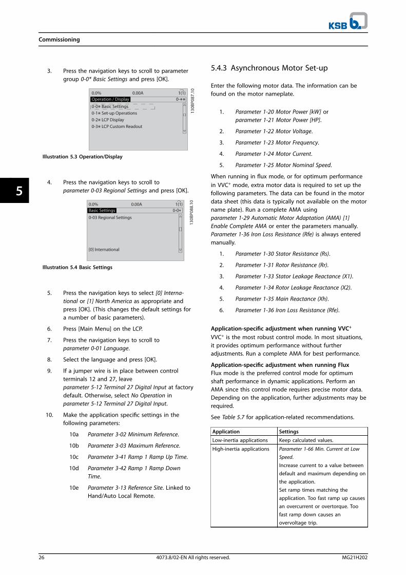
3. Press the navigation keys to scroll to parametergroup 0-0* Basic Settings and press [OK].
Illustration 5.3 Operation/Display
4. Press the navigation keys to scroll toparameter 0-03 Regional Settings and press [OK].
Illustration 5.4 Basic Settings
5. Press the navigation keys to select [0] Interna-tional or [1] North America as appropriate andpress [OK]. (This changes the default settings fora number of basic parameters).
6. Press [Main Menu] on the LCP.
7. Press the navigation keys to scroll toparameter 0-01 Language.
8. Select the language and press [OK].
9. If a jumper wire is in place between controlterminals 12 and 27, leaveparameter 5-12 Terminal 27 Digital Input at factorydefault. Otherwise, select No Operation inparameter 5-12 Terminal 27 Digital Input.
10. Make the application specific settings in thefollowing parameters:
10a Parameter 3-02 Minimum Reference.
10b Parameter 3-03 Maximum Reference.
10c Parameter 3-41 Ramp 1 Ramp Up Time.
10d Parameter 3-42 Ramp 1 Ramp DownTime.
10e Parameter 3-13 Reference Site. Linked toHand/Auto Local Remote.
5.4.3 Asynchronous Motor Set-up
Enter the following motor data. The information can befound on the motor nameplate.
1. Parameter 1-20 Motor Power [kW] orparameter 1-21 Motor Power [HP].
2. Parameter 1-22 Motor Voltage.
3. Parameter 1-23 Motor Frequency.
4. Parameter 1-24 Motor Current.
5. Parameter 1-25 Motor Nominal Speed.
When running in flux mode, or for optimum performancein VVC+ mode, extra motor data is required to set up thefollowing parameters. The data can be found in the motordata sheet (this data is typically not available on the motorname plate). Run a complete AMA usingparameter 1-29 Automatic Motor Adaptation (AMA) [1]Enable Complete AMA or enter the parameters manually.Parameter 1-36 Iron Loss Resistance (Rfe) is always enteredmanually.
1. Parameter 1-30 Stator Resistance (Rs).
2. Parameter 1-31 Rotor Resistance (Rr).
3. Parameter 1-33 Stator Leakage Reactance (X1).
4. Parameter 1-34 Rotor Leakage Reactance (X2).
5. Parameter 1-35 Main Reactance (Xh).
6. Parameter 1-36 Iron Loss Resistance (Rfe).
Application-specific adjustment when running VVC+
VVC+ is the most robust control mode. In most situations,it provides optimum performance without furtheradjustments. Run a complete AMA for best performance.
Application-specific adjustment when running FluxFlux mode is the preferred control mode for optimumshaft performance in dynamic applications. Perform anAMA since this control mode requires precise motor data.Depending on the application, further adjustments may berequired.
See Table 5.7 for application-related recommendations.
Application Settings
Low-inertia applications Keep calculated values.
High-inertia applications Parameter 1-66 Min. Current at LowSpeed.Increase current to a value betweendefault and maximum depending onthe application.Set ramp times matching theapplication. Too fast ramp up causesan overcurrent or overtorque. Toofast ramp down causes anovervoltage trip.
Commissioning
26 4073.8/02-EN All rights reserved. MG21H202
55

Application Settings
High load at low speed Parameter 1-66 Min. Current at LowSpeed.Increase current to a value betweendefault and maximum depending onthe application.
No-load application Adjust parameter 1-18 Min. Current at
No Load to achieve smoother motoroperation by reducing torque rippleand vibration.
Flux sensorless only Adjust parameter 1-53 Model Shift
Frequency.Example 1: If the motor oscillates at5 Hz and dynamics performance isrequired at 15 Hz, setparameter 1-53 Model Shift Frequencyto 10 Hz.Example 2: If the applicationinvolves dynamic load changes atlow speed, reduceparameter 1-53 Model Shift Frequency.Observe the motor behaviour tomake sure that the model shiftfrequency is not reduced too much.Symptoms of inappropriate modelshift frequency are motor oscillationsor frequency converter tripping.
Table 5.7 Recommendations for Flux Applications
5.4.4 PM Motor Setup in VVC+
NOTICEOnly use permanent magnet (PM) motor with fans andpumps.
Initial programming steps
1. Activate PM motor operationParameter 1-10 Motor Construction, select [1] PM,non salient SPM.
2. Set parameter 0-02 Motor Speed Unit to [0] RPM.
Programming motor dataAfter selecting PM motor in parameter 1-10 MotorConstruction, the PM motor-related parameters inparameter groups 1-2* Motor Data, 1-3* Adv. Motor Dataand 1-4* are active.The necessary data can be found on the motor nameplateand in the motor data sheet.Programme the following parameters in the listed order:
1. Parameter 1-24 Motor Current.
2. Parameter 1-26 Motor Cont. Rated Torque.
3. Parameter 1-25 Motor Nominal Speed.
4. Parameter 1-39 Motor Poles.
5. Parameter 1-30 Stator Resistance (Rs).Enter line to common stator winding resistance(Rs). If only line-line data is available, divide theline-line value with 2 to achieve the line tocommon (starpoint) value.
6. Parameter 1-37 d-axis Inductance (Ld).Enter line to common direct axis inductance ofthe PM motor.If only line-line data is available, divide the line-line value by 2 to achieve the line-common(starpoint) value.
7. Parameter 1-40 Back EMF at 1000 RPM.Enter line-to-line back EMF of the PM motor at1000 RPM mechanical speed (RMS value). BackEMF is the voltage generated by a PM motorwhen no frequency converter is connected andthe shaft is turned externally. Back EMF isnormally specified for nominal motor speed or for1000 RPM measured between 2 lines. If the valueis not available for a motor speed of 1000 RPM,calculate the correct value as follows: If back EMFis for example 320 V at 1800 RPM, it can becalculated at 1000 RPM as follows: Back EMF =(Voltage / RPM)*1000 = (320/1800)*1000 = 178.This is the value that must be programmed forparameter 1-40 Back EMF at 1000 RPM.
Test Motor Operation
1. Start the motor at low speed (100–200 RPM). Ifthe motor does not turn, check installation,general programming, and motor data.
2. Check if the start function in parameter 1-70 PMStart Mode fits the application requirements.
Rotor detectionThis function is the recommended choice for applicationswhere the motor starts from standstill, for example pumpsor conveyors. On some motors, an acoustic sound is heardwhen the impulse is sent out. This does not harm themotor.
ParkingThis function is the recommended choice for applicationswhere the motor is rotating at slow speed, for examplewindmilling in fan applications. Parameter 2-06 ParkingCurrent and parameter 2-07 Parking Time can be adjusted.Increase the factory setting of these parameters forapplications with high inertia.
Start the motor at nominal speed. If the application doesnot run well, check the VVC+ PM settings. Recommen-dations in different applications can be found in Table 5.7.
Commissioning
MG21H202 4073.8/02-EN All rights reserved. 27
5 5

Application Settings
Low inertia applicationsILoad/IMotor <5
Parameter 1-17 Voltage filter timeconst. to be increased by factor 5–10.Parameter 1-14 Damping Gain shouldbe reduced.Parameter 1-66 Min. Current at LowSpeed should be reduced (<100%).
Low inertia applications50>ILoad/IMotor >5
Keep calculated values.
High inertia applications
ILoad/IMotor > 50
Parameter 1-14 Damping Gain,
parameter 1-15 Low Speed Filter TimeConst., and parameter 1-16 HighSpeed Filter Time Const. should beincreased.
High load at low speed
<30% (rated speed)
Parameter 1-17 Voltage filter time
const. should be increased.Parameter 1-66 Min. Current at LowSpeed should be increased (>100%for a prolonged time can overheatthe motor).
Table 5.8 Recommendations in Different Applications
If the motor starts oscillating at a certain speed, increaseparameter 1-14 Damping Gain. Increase the value in smallsteps. Depending on the motor, a good value for thisparameter can be 10% or 100% higher than the defaultvalue.
The starting torque can be adjusted in parameter 1-66 Min.Current at Low Speed. 100% provides nominal torque asstarting torque.
5.4.5 SynRM Motor Set-up with VVC+
This section describes how to set up a SynRM motor withVVC+.
NOTICEThe SmartStart wizard covers the basic configuration ofSynRM motors.
Initial programming stepsTo activate SynRM motor operation, select [5] Sync.Reluctance in parameter 1-10 Motor Construction.
Programming motor dataAfter performing the initial programming steps, the SynRMmotor-related parameters in parameter groups 1-2* MotorData, 1-3* Adv. Motor Data, and 1-4* Adv. Motor Data II areactive. Use the motor nameplate data and the motor datasheet to programme the following parameters in the orderlisted:
• Parameter 1-23 Motor Frequency.
• Parameter 1-24 Motor Current.
• Parameter 1-25 Motor Nominal Speed.
• Parameter 1-26 Motor Cont. Rated Torque.
Run a complete AMA using parameter 1-29 AutomaticMotor Adaptation (AMA) [1] Enable Complete AMA or enterthe following parameters manually:
• Parameter 1-30 Stator Resistance (Rs).
• Parameter 1-37 d-axis Inductance (Ld).
• Parameter 1-44 d-axis Inductance Sat. (LdSat).
• Parameter 1-45 q-axis Inductance Sat. (LqSat).
• Parameter 1-48 Inductance Sat. Point.
Application-specific adjustmentsStart the motor at nominal speed. If the application doesnot run well, check the VVC+ SynRM settings. Table 5.9provides application-specific recommendations:
Commissioning
28 4073.8/02-EN All rights reserved. MG21H202
55

Application Settings
Low-inertia applicationsILoad/IMotor <5
Increase parameter 1-17 Voltage filtertime const. by factor 5 to 10.Reduce parameter 1-14 DampingGain.Reduce parameter 1-66 Min. Currentat Low Speed (<100%).
Low-inertia applications50>ILoad/IMotor >5
Keep the default values.
High-inertia applicationsILoad/IMotor > 50
Increase parameter 1-14 DampingGain, parameter 1-15 Low Speed FilterTime Const., and parameter 1-16 HighSpeed Filter Time Const.
High-load at low speed<30% (rated speed)
Increase parameter 1-17 Voltage filtertime const.Increase parameter 1-66 Min. Currentat Low Speed to adjust the startingtorque. 100% current providesnominal torque as starting torque.This parameter is independent ofparameter 30-20 High Starting TorqueTime [s] and parameter 30-21 HighStarting Torque Current [%]). Workingat a current level higher than 100%for a prolonged time can cause themotor to overheat.
Dynamic applications Increase parameter 14-41 AEOMinimum Magnetisation for highlydynamic applications. Adjustingparameter 14-41 AEO MinimumMagnetisation ensures a goodbalance between energy efficiencyand dynamics. Adjustparameter 14-42 Minimum AEOFrequency to specify the minimumfrequency at which the frequencyconverter should use minimummagnetisation.
Table 5.9 Recommendations for Various Applications
If the motor starts oscillating at a certain speed, increaseparameter 1-14 Damping Gain. Increase the damping gainvalue in small steps. Depending on the motor, thisparameter can be set to 10–100% higher than the defaultvalue.
5.4.6 Automatic Energy Optimisation (AEO)
NOTICEAEO is not relevant for permanent magnet motors.
AEO is a procedure which minimises voltage to the motor,thereby reducing energy consumption, heat, and noise.
To activate AEO, set parameter 1-03 Torque Characteristics to[2] Auto Energy Optim. CT or [3] Auto Energy Optim. VT.
5.4.7 Automatic Motor Adaptation (AMA)
AMA is a procedure which optimises compatibility betweenthe frequency converter and the motor.
• The frequency converter builds a mathematicalmodel of the motor for regulating output motorcurrent. The procedure also tests the input phasebalance of electrical power. It compares themotor characteristics with the entered nameplatedata.
• The motor shaft does not turn and no harm isdone to the motor while running the AMA.
• Some motors may be unable to run the completeversion of the test. In that case, select [2] Enablereduced AMA.
• If an output filter is connected to the motor,select [2] Enable reduced AMA.
• If warnings or alarms occur, see chapter 7.4 List ofWarnings and Alarms.
• Run this procedure on a cold motor for bestresults.
To run AMA1. Press [Main Menu] to access parameters.
2. Scroll to parameter group 1-** Load and Motorand press [OK].
3. Scroll to parameter group 1-2* Motor Data andpress [OK].
4. Scroll to parameter 1-29 Automatic MotorAdaptation (AMA) and press [OK].
5. Select [1] Enable complete AMA and press [OK].
6. Follow the on-screen instructions.
7. The test runs automatically and indicates when itis complete.
8. The advanced motor data is entered in parametergroup 1-3* Adv. Motor Data.
5.5 Checking Motor Rotation
NOTICERisk of damage to pumps/compressors caused by motorrunning in wrong direction. Before running thefrequency converter, check the motor rotation.
The motor runs briefly at 5 Hz or the minimum frequencyset in parameter 4-12 Motor Speed Low Limit [Hz].
Commissioning
MG21H202 4073.8/02-EN All rights reserved. 29
5 5

1. Press [Main Menu].
2. Scroll to parameter 1-28 Motor Rotation Check andpress [OK].
3. Scroll to [1] Enable.
The following text appears: Note! Motor may run in wrongdirection.
4. Press [OK].
5. Follow the on-screen instructions.
NOTICETo change the direction of rotation, remove power to thefrequency converter and wait for power to discharge.Reverse the connection of any 2 of the 3 motor wires onthe motor or frequency converter side of the connection.
5.6 Local-control Test
1. Press [Hand On] to provide a local start commandto the frequency converter.
2. Accelerate the frequency converter by pressing[] to full speed. Moving the cursor left of thedecimal point provides quicker input changes.
3. Note any acceleration problems.
4. Press [Off]. Note any deceleration problems.
In the event of acceleration or deceleration problems, see chapter 7.5 Troubleshooting. See chapter 7.4 List of Warningsand Alarms for resetting the frequency converter after atrip.
Commissioning
30 4073.8/02-EN All rights reserved. MG21H202
55

5.7 System Start-up
The procedure in this section requires user-wiring andapplication programming to be completed. The followingprocedure is recommended after application set-up iscompleted.
1. Press [Auto On].
2. Apply an external run command.
3. Adjust the speed reference throughout the speedrange.
4. Remove the external run command.
5. Check the sound and vibration levels of themotor to ensure that the system is working asintended.
If warnings or alarms occur, see chapter 7.3 Warning andAlarm Types or chapter 7.4 List of Warnings and Alarms.
Commissioning
MG21H202 4073.8/02-EN All rights reserved. 31
5 5
6 Application Set-up Examples
The examples in this section are intended as a quickreference for common applications.
• Parameter settings are the regional default valuesunless otherwise indicated (selected inparameter 0-03 Regional Settings).
• Parameters associated with the terminals andtheir settings are shown next to the drawings.
• Required switch settings for analog terminals A53or A54 are also shown.
NOTICEWhen using the optional STO feature, a jumper wire maybe required between terminal 12 (or 13) and terminal 37for the frequency converter to operate with factorydefault programming values.
6.1 Application Examples
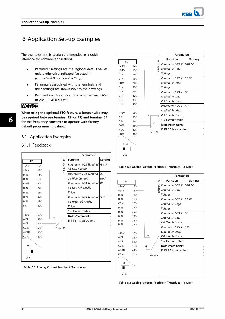
6.1.1 Feedback
Parameters
Function Setting
Parameter 6-22 Terminal54 Low Current
4 mA*
Parameter 6-23 Terminal
54 High Current
20
mA*
Parameter 6-24 Terminal54 Low Ref./Feedb.Value
0*
Parameter 6-25 Terminal54 High Ref./Feedb.Value
50*
* = Default value
Notes/comments:D IN 37 is an option.
Table 6.1 Analog Current Feedback Transducer
Parameters
Function Setting
Parameter 6-20 Terminal 54 LowVoltage
0.07 V*
Parameter 6-21 T
erminal 54 HighVoltage
10 V*
Parameter 6-24 T
erminal 54 LowRef./Feedb. Value
0*
Parameter 6-25 Terminal 54 HighRef./Feedb. Value
50*
* = Default value
Notes/comments:D IN 37 is an option.
Table 6.2 Analog Voltage Feedback Transducer (3-wire)
Parameters
Function Setting
Parameter 6-20 T
erminal 54 LowVoltage
0.07 V*
Parameter 6-21 Terminal 54 HighVoltage
10 V*
Parameter 6-24 Terminal 54 LowRef./Feedb. Value
0*
Parameter 6-25 Terminal 54 HighRef./Feedb. Value
50*
* = Default value
Notes/comments:D IN 37 is an option.
Table 6.3 Analog Voltage Feedback Transducer (4-wire)
Application Set-up Examples
32 4073.8/02-EN All rights reserved. MG21H202
66

6.1.2 Speed
Parameters
Function Setting
Parameter 6-10 Terminal 53 LowVoltage
0.07 V*
Parameter 6-11 T
erminal 53 HighVoltage
10 V*
Parameter 6-14 T
erminal 53 LowRef./Feedb. Value
0 Hz
Parameter 6-15 Terminal 53 HighRef./Feedb. Value
50 Hz
* = Default value
Notes/comments:D IN 37 is an option.
Table 6.4 Analog Speed Reference (Voltage)
Parameters
Function Setting
Parameter 6-12 Terminal 53 LowCurrent
4 mA*
Parameter 6-13 Terminal 53 HighCurrent
20 mA*
Parameter 6-14 Terminal 53 LowRef./Feedb. Value
0 Hz
Parameter 6-15 T
erminal 53 HighRef./Feedb. Value
50 Hz
* = Default value
Notes/comments:D IN 37 is an option.
Table 6.5 Analog Speed Reference (Current)
Parameters
Function Setting
Parameter 6-10 T
erminal 53 LowVoltage
0.07 V*
Parameter 6-11 Terminal 53 HighVoltage
10 V*
Parameter 6-14 Terminal 53 LowRef./Feedb. Value
0 Hz
Parameter 6-15 Terminal 53 HighRef./Feedb. Value
50 Hz
* = Default value
Notes/comments:D IN 37 is an option.
Table 6.6 Speed Reference (Using a Manual Potentiometer)
6.1.3 Run/Stop
Parameters
Function Setting
Parameter 5-10 Terminal 18Digital Input
[8] Start*
Parameter 5-12 Terminal 27Digital Input
[7] Externalinterlock
* = Default value
Notes/comments:D IN 37 is an option.
Table 6.7 Run/Stop Command with External Interlock
Application Set-up Examples
MG21H202 4073.8/02-EN All rights reserved. 33
6 6

Parameters
Function Setting
Parameter 5-10 T
erminal 18Digital Input
[8] Start*
Parameter 5-12 Terminal 27Digital Input
[7] Externalinterlock
* = Default value
Notes/comments:If parameter 5-12 Terminal 27Digital Input is set to [0] nooperation, a jumper wire toterminal 27 is not needed.D IN 37 is an option.
Table 6.8 Run/Stop Command without External Interlock
Parameters
Function Setting
Parameter 5-10 Terminal 18Digital Input
[8] Start*
Parameter 5-11 T
erminal 19Digital Input
[52] Run
Permissive
Parameter 5-12 Terminal 27Digital Input
[7] Externalinterlock
Parameter 5-40 Function Relay
[167] Startcommandact.
* = Default value
Notes/comments:D IN 37 is an option.
Table 6.9 Run Permissive
6.1.4 External Alarm Reset
Parameters
Function Setting
Parameter 5-11 Terminal 19Digital Input
[1] Reset
* = Default Value
Notes/comments:D IN 37 is an option.
Table 6.10 External Alarm Reset
Application Set-up Examples
34 4073.8/02-EN All rights reserved. MG21H202
66

6.1.5 RS485
Parameters
Function Setting
Parameter 8-30 Protocol FC*
Parameter 8-31
Address
1*
Parameter 8-32
Baud Rate
9600*
* = Default Value
Notes/comments:Select protocol, address andbaud rate in the abovementioned parameters.D IN 37 is an option.
Table 6.11 RS485 Network Connection
6.1.6 Motor Thermistor
WARNINGTHERMISTOR INSULATIONRisk of personal injury or equipment damage.
• Use only thermistors with reinforced or doubleinsulation to meet PELV insulationrequirements.
Parameters
Function Setting
Parameter 1-90 Motor ThermalProtection
[2]Thermistortrip
Parameter 1-93 Thermistor Source
[1] Analoginput 53
* = Default Value
Notes/comments:If only a warning is desired,parameter 1-90 Motor ThermalProtection should be set to [1]
Thermistor warning.D IN 37 is an option.
Table 6.12 Motor Thermistor
Application Set-up Examples
MG21H202 4073.8/02-EN All rights reserved. 35
6 6
7 Maintenance, Diagnostics and Troubleshooting
This chapter includes maintenance and service guidelines,status messages, warnings and alarms, and basic trouble-shooting.
7.1 Maintenance and Service
Under normal operating conditions and load profiles, thefrequency converter is maintenance-free throughout itsdesigned lifetime. To prevent breakdown, danger, anddamage, examine the frequency converter at regularintervals depending on the operating conditions. Replaceworn or damaged parts with original spare parts orstandard parts.
WARNINGUNINTENDED STARTWhen the frequency converter is connected to AC mains,DC power supply, or load sharing, the motor may start atany time. Unintended start during programming, service,or repair work can result in death, serious injury, orproperty damage. The motor can start by means of anexternal switch, a serial bus command, an inputreference signal from the LCP or LOP, via remoteoperation using MCT 10 Set-up Software, or after acleared fault condition.
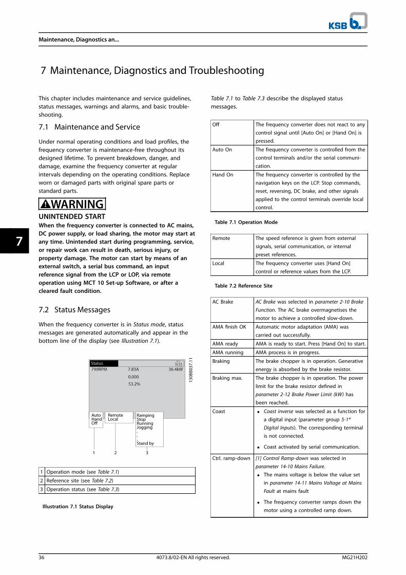
7.2 Status Messages
When the frequency converter is in Status mode, statusmessages are generated automatically and appear in thebottom line of the display (see Illustration 7.1).
1 Operation mode (see Table 7.1)
2 Reference site (see Table 7.2)
3 Operation status (see Table 7.3)
Illustration 7.1 Status Display
Table 7.1 to Table 7.3 describe the displayed statusmessages.
Off The frequency converter does not react to any
control signal until [Auto On] or [Hand On] ispressed.
Auto On The frequency converter is controlled from thecontrol terminals and/or the serial communi-cation.
Hand On The frequency converter is controlled by thenavigation keys on the LCP. Stop commands,reset, reversing, DC brake, and other signalsapplied to the control terminals override localcontrol.
Table 7.1 Operation Mode
Remote The speed reference is given from externalsignals, serial communication, or internalpreset references.
Local The frequency converter uses [Hand On]control or reference values from the LCP.
Table 7.2 Reference Site
AC Brake AC Brake was selected in parameter 2-10 BrakeFunction. The AC brake overmagnetises themotor to achieve a controlled slow-down.
AMA finish OK Automatic motor adaptation (AMA) wascarried out successfully.
AMA ready AMA is ready to start. Press [Hand On] to start.
AMA running AMA process is in progress.
Braking The brake chopper is in operation. Generative
energy is absorbed by the brake resistor.
Braking max. The brake chopper is in operation. The power
limit for the brake resistor defined inparameter 2-12 Brake Power Limit (kW) hasbeen reached.
Coast • Coast inverse was selected as a function fora digital input (parameter group 5-1*Digital Inputs). The corresponding terminal
is not connected.
• Coast activated by serial communication.
Ctrl. ramp-down [1] Control Ramp-down was selected in
parameter 14-10 Mains Failure.
• The mains voltage is below the value setin parameter 14-11 Mains Voltage at MainsFault at mains fault
• The frequency converter ramps down themotor using a controlled ramp down.
Maintenance, Diagnostics an...
36 4073.8/02-EN All rights reserved. MG21H202
77

Current High The frequency converter output current isabove the limit set in parameter 4-51 WarningCurrent High.
Current Low The frequency converter output current isbelow the limit set in parameter 4-52 WarningSpeed Low.
DC Hold [1] DC hold is selected inparameter 1-80 Function at Stop and a stopcommand is active. The motor is held by a DCcurrent set in parameter 2-00 DC Hold/PreheatCurrent.
DC Stop The motor is held with a DC current(parameter 2-01 DC Brake Current) for aspecified time (parameter 2-02 DC BrakingTime).
• The DC Brake cut in speed is reached inparameter 2-03 DC Brake Cut In Speed [RPM]and a stop command is active.
• DC Brake (inverse) is selected as a functionfor a digital input (parameter group 5-1*Digital Inputs). The corresponding terminalis not active.
• The DC Brake is activated via serialcommunication.
Feedback high The sum of all active feedbacks is above thefeedback limit set in parameter 4-57 WarningFeedback High.
Feedback low The sum of all active feedbacks is below thefeedback limit set in parameter 4-56 WarningFeedback Low.
Freeze output The remote reference is active, which holdsthe present speed.
• Freeze output was selected as a function fora digital input (parameter group 5-1*Digital Inputs). The corresponding terminalis active. Speed control is only possible viathe terminal functions Speed Up and SpeedDown.
• Hold ramp is activated via serial communi-cation.
Freeze outputrequest
A freeze output command was given, but themotor remains stopped until a run permissivesignal is received.
Freeze ref. Freeze Reference was selected as a function for
a digital input (parameter group 5-1* DigitalInputs). The corresponding terminal is active.The frequency converter saves the actualreference. Changing the reference is now onlypossible via terminal functions Speed Up andSpeed Down.
Jog request A jog command was given, but the motorremains stopped until a run permissive signalis received via a digital input.
Jogging The motor is running as programmed inparameter 3-19 Jog Speed [RPM].
• Jog was selected as a function for a digitalinput (parameter group 5-1* Digital Inputs).The corresponding terminal (for exampleTerminal 29) is active.
• The Jog function is activated via the serialcommunication.
• The Jog function was selected as areaction for a monitoring function (forexample No signal). The monitoring
function is active.
Motor check In parameter 1-80 Function at Stop, [2] MotorCheck was selected. A stop command is active.To ensure that a motor is connected to thefrequency converter, a permanent test currentis applied to the motor.
OVC control Overvoltage control was activated inparameter 2-17 Over-voltage Control, [2]Enabled. The connected motor supplies thefrequency converter with generative energy.The overvoltage control adjusts the V/Hz ratioto run the motor in controlled mode and toprevent the frequency converter from tripping.
PowerUnit Off (Only frequency converters with an external 24V power supply installed).Mains supply to the frequency converter wasremoved, and the control card is supplied bythe external 24 V.
Protection md Protection mode is active. The unit hasdetected a critical status (overcurrent orovervoltage).
• To avoid tripping, switching frequency isreduced to 4 kHz.
• If possible, protection mode ends afterapproximately 10 s.
• Protection mode can be restricted inparameter 14-26 Trip Delay at Inverter Fault.
QStop The motor is decelerating usingparameter 3-81 Quick Stop Ramp Time.
• Quick stop inverse was selected as afunction for a digital input (parametergroup 5-1* Digital Inputs). Thecorresponding terminal is not active.
• The quick stop function was activated viaserial communication.
Ramping The motor is accelerating/decelerating usingthe active ramp up/down. The reference, alimit value, or a standstill is not yet reached.
Ref. high The sum of all active references is above thereference limit set in parameter 4-55 WarningReference High.
Maintenance, Diagnostics an...
MG21H202 4073.8/02-EN All rights reserved. 37
7 7

Ref. low The sum of all active references is below thereference limit set in parameter 4-54 WarningReference Low.
Run on ref. The frequency converter is running in thereference range. The feedback value matchesthe setpoint value.
Run request A start command was given, but the motorremains stopped until a run permissive signalis received via digital input.
Running The motor is driven by the frequency
converter.
Sleep Mode The energy-saving function is enabled. Themotor has stopped, but restarts automaticallywhen required.
Speed high Motor speed is above the value set inparameter 4-53 Warning Speed High.
Speed low Motor speed is below the value set inparameter 4-52 Warning Speed Low.
Standby In Auto On mode, the frequency converterstarts the motor with a start signal from adigital input or serial communication.
Start delay In parameter 1-71 Start Delay, a delay startingtime was set. A start command is activatedand the motor starts after the start delay timeexpires.
Start fwd/rev Start forward and start reverse were selected as
functions for 2 different digital inputs(parameter group 5-1* Digital Inputs). Themotor starts in forward or reverse directiondepending on which corresponding terminal isactivated.
Stop The frequency converter has received a stop
command from the LCP, digital input, or serialcommunication.
Trip An alarm occurred and the motor is stopped.
Once the cause of the alarm is cleared, thefrequency converter can be reset manually bypressing [Reset] or remotely by control
terminals or serial communication.
Trip lock An alarm occurred and the motor is stopped.Once the cause of the alarm is cleared, powermust be cycled to the frequency converter.The frequency converter can then be resetmanually by pressing [Reset], or remotely bycontrol terminals or serial communication.
Table 7.3 Operation Status
NOTICEIn auto/remote mode, the frequency converter requiresexternal commands to execute functions.
7.3 Warning and Alarm Types
WarningsA warning is issued when an alarm condition is impendingor when an abnormal operating condition is present andmay result in the frequency converter issuing an alarm. Awarning clears by itself when the abnormal conditionceases.
AlarmsTripAn alarm is issued when the frequency converter istripped, meaning that the frequency converter suspendsoperation to prevent frequency converter or systemdamage. The motor coasts to a stop. The frequencyconverter logic continues to operate and monitor thefrequency converter status. After the fault condition isremedied, the frequency converter can be reset. It is thenready to start operation again.
Resetting the frequency converter after trip/trip lockA trip can be reset in any of 4 ways:
• Press [Reset] on the LCP.
• Digital reset input command.
• Serial communication reset input command.
• Auto reset.
Trip lockInput power is cycled. The motor coasts to a stop. Thefrequency converter continues to monitor the frequencyconverter status. Remove input power to the frequencyconverter, correct the cause of the fault, and reset thefrequency converter.
Warning and alarm displays
• A warning is displayed in the LCP along with thewarning number.
• An alarm flashes along with the alarm number.
Illustration 7.2 Alarm Display Example
Maintenance, Diagnostics an...
38 4073.8/02-EN All rights reserved. MG21H202
77

In addition to the text and alarm code in the LCP, there are3 status indicator lights.
Warning indicator light Alarm indicator light
Warning On Off
Alarm Off On (Flashing)
Trip-Lock On On (Flashing)
Illustration 7.3 Status Indicator Lights
7.4 List of Warnings and Alarms
The warning/alarm information in this chapter defines eachwarning/alarm condition, provides the probable cause forthe condition, and details a remedy or troubleshootingprocedure.
WARNING 1, 10 Volts lowThe control card voltage from terminal 50 is <10 V.Remove some of the load from terminal 50, as the 10 Vsupply is overloaded. Maximum 15 mA or minimum 590 Ω.
A short circuit in a connected potentiometer or improperwiring of the potentiometer can cause this condition.
Troubleshooting• Remove the wiring from terminal 50.
• If the warning clears, the problem is with thecustomer wiring.
• If the warning does not clear, replace the controlcard.
WARNING/ALARM 2, Live zero errorThis warning or alarm only appears if programmed inparameter 6-01 Live Zero Timeout Function. The signal onone of the analog inputs is less than 50% of the minimumvalue programmed for that input. Broken wiring or signalsbeing sent by a faulty device causes this condition.
Troubleshooting• Check connections on all the analog input
terminals. Control card terminals 53 and 54 forsignals, terminal 55 common. MCB 101 terminals11 and 12 for signals, terminal 10 common. MCB109 terminals 1, 3, 5 for signals, terminals 2, 4, 6common).
• Check that the frequency converter programmingand switch settings match the analog signal type.
• Perform an input terminal signal test.
WARNING/ALARM 3, No motorNo motor has been connected to the output of thefrequency converter.
WARNING/ALARM 4, Mains phase lossA phase is missing on the supply side, or the mainsvoltage imbalance is too high. This message also appearsin case of a fault in the input rectifier on the frequencyconverter. Options are programmed inparameter 14-12 Function at Mains Imbalance.
Troubleshooting• Check the supply voltage and supply currents to
the frequency converter.
WARNING 5, DC link voltage highThe intermediate circuit voltage (DC) is higher than thehigh-voltage warning limit. The limit depends on thefrequency converter voltage rating. The unit is still active.
WARNING 6, DC link voltage lowThe intermediate circuit voltage (DC) is lower than the low-voltage warning limit. The limit depends on the frequencyconverter voltage rating. The unit is still active.
WARNING/ALARM 7, DC overvoltageIf the intermediate circuit voltage exceeds the limit, thefrequency converter trips after some time.
Troubleshooting• Connect a brake resistor.
• Extend the ramp time.
• Change the ramp type.
• Activate the functions in parameter 2-10 BrakeFunction.
• Increase parameter 14-26 Trip Delay at InverterFault.
WARNING/ALARM 8, DC under voltageIf the intermediate circuit voltage (DC link) drops belowthe undervoltage limit, the frequency converter checks if a24 V DC back-up supply is connected. If no 24 V DC back-up supply is connected, the frequency converter trips aftera fixed time delay. The time delay varies with unit size.
Troubleshooting• Check that the supply voltage matches the
frequency converter voltage.
• Perform an input voltage test.
Maintenance, Diagnostics an...
MG21H202 4073.8/02-EN All rights reserved. 39
7 7
• Perform a soft charge circuit test.
WARNING/ALARM 9, Inverter overloadThe frequency converter is about to cut out because of anoverload (too high current for too long). The counter forelectronic thermal inverter protection issues a warning at98% and trips at 100%, while issuing an alarm. Thefrequency converter cannot be reset until the counter isbelow 90%.
Troubleshooting• Compare the output current shown on the LCP
with the frequency converter rated current.
• Compare the output current shown on the LCPwith measured motor current.
• Display the thermal drive load on the LCP andmonitor the value. When running above thefrequency converter continuous current rating,the counter should increase. When running belowthe frequency converter continuous currentrating, the counter should decrease.
WARNING/ALARM 10, Motor overload temperatureAccording to the electronic thermal protection (ETR), themotor is too hot. Select whether the frequency converterissues a warning or an alarm when the counter reaches100% in parameter 1-90 Motor Thermal Protection. The faultoccurs when the motor overload exceeds 100% for toolong.
Troubleshooting• Check for motor overheating.
• Check if the motor is mechanically overloaded.
• Check that the motor current set inparameter 1-24 Motor Current is correct.
• Ensure the motor data in parameters 1-20through 1-25 is set correctly.
• If an external fan is used, check that it is selectedin parameter 1-91 Motor External Fan.
• Running AMA in parameter 1-29 Automatic MotorAdaptation (AMA) tunes the frequency converterto the motor more accurately and reducesthermal loading.
WARNING/ALARM 11, Motor thermistor overtempThe thermistor might be disconnected. Select whether thefrequency converter issues a warning or an alarm inparameter 1-90 Motor Thermal Protection.
Troubleshooting• Check for motor overheating.
• Check if the motor is mechanically overloaded.
• Check that the thermistor is connected correctlybetween either terminal 53 or 54 (analog voltageinput) and terminal 50 (+10 V supply) and thatthe terminal switch for 53 or 54 is set for voltage.
Check parameter 1-93 Thermistor Source selectsterminal 53 or 54.
• When using digital inputs 18 or 19, check thatthe thermistor is connected correctly betweeneither terminal 18 or 19 (digital input PNP only)and terminal 50.
• If a KTY sensor is used, check for correctconnection between terminals 54 and 55.
• If using a thermal switch or thermistor, check thatthe programming if parameter 1-93 ThermistorSource matches sensor wiring.
• If using a KTY sensor, check the programming ofparameter 1-95 KTY Sensor Type, andparameter 1-97 KTY Threshold level match sensorwiring.
WARNING/ALARM 12, Torque limitThe torque has exceeded the value inparameter 4-16 Torque Limit Motor Mode or the value inparameter 4-17 Torque Limit Generator Mode.Parameter 14-25 Trip Delay at Torque Limit can change thisfrom a warning-only condition to a warning followed by analarm.
Troubleshooting• If the motor torque limit is exceeded during
ramp-up, extend the ramp-up time.
• If the generator torque limit is exceeded duringramp down, extend the ramp-down time.
• If torque limit occurs while running, possiblyincrease the torque limit. Be sure that the systemcan operate safely at a higher torque.
• Check the application for excessive current drawon the motor.
WARNING/ALARM 13, Over currentThe inverter peak current limit (approximately 200% of therated current) is exceeded. The warning lasts about 1.5 s,then the frequency converter trips and issues an alarm.Shock loading or fast acceleration with high-inertia loadscan cause this fault. If extended mechanical brake controlis selected, the trip can be reset externally.
Troubleshooting• Remove power and check if the motor shaft can
be turned.
• Check that the motor size matches the frequencyconverter.
• Check parameters 1-20 to 1-25 for correct motordata.
ALARM 14, Earth (ground) faultThere is current from the output phases to ground, eitherin the cable between the frequency converter and themotor or in the motor itself.
Maintenance, Diagnostics an...
40 4073.8/02-EN All rights reserved. MG21H202
77

Troubleshooting• Remove power from the frequency converter and
repair the ground fault.
• Check for ground faults in the motor bymeasuring the resistance to ground of the motorleads and the motor with a megohmmeter.
• Perform current sensor test.
ALARM 15, Hardware mismatchA fitted option is not operational with the present controlboard hardware or software.
Record the value of the following parameters and contactthe local KSB supplier:
• Parameter 15-40 FC Type.
• Parameter 15-41 Power Section.
• Parameter 15-42 Voltage.
• Parameter 15-43 Software Version.
• Parameter 15-45 Actual Typecode String.
• Parameter 15-49 SW ID Control Card.
• Parameter 15-50 SW ID Power Card.
• Parameter 15-60 Option Mounted.
• Parameter 15-61 Option SW Version (for eachoption slot).
ALARM 16, Short circuitThere is short-circuiting in the motor or motor wiring.
Troubleshooting• Remove power from the frequency converter and
repair the short circuit.
WARNING/ALARM 17, Control word timeoutThere is no communication to the frequency converter.The warning is only active when parameter 8-04 ControlWord Timeout Function is NOT set to [0] Off.If parameter 8-04 Control Word Timeout Function is set to [5]Stop and trip, a warning appears and the frequencyconverter ramps down until it trips, then it displays analarm.
Troubleshooting• Check the connections on the serial communi-
cation cable.
• Increase parameter 8-03 Control Word TimeoutTime.
• Check the operation of the communicationequipment.
• Verify a proper installation based on EMCrequirements.
WARNING/ALARM 22, Hoist mechanical brakeWhen this warning is active, the LCP shows the type ofissue.0 = The torque ref. was not reached before timeout.1 = There was no brake feedback before timeout.
WARNING 23, Internal fan faultThe fan warning function is an extra protective functionthat checks if the fan is running/mounted. The fan warningcan be disabled in parameter 14-53 Fan Monitor ([0]Disabled).
Troubleshooting• Check the fan resistance.
• Check the soft charge fuses.
WARNING 24, External fan faultThe fan warning function is an extra protective functionthat checks if the fan is running/mounted. The fan warningcan be disabled in parameter 14-53 Fan Monitor ([0]Disabled).
Troubleshooting• Check the fan resistance.
• Check the soft charge fuses.
WARNING 25, Brake resistor short circuitThe brake resistor is monitored during operation. If a shortcircuit occurs, the brake function is disabled and thewarning appears. The frequency converter is stilloperational but without the brake function. Remove powerfrom the frequency converter and replace the brakeresistor (see parameter 2-15 Brake Check).
WARNING/ALARM 26, Brake resistor power limitThe power transmitted to the brake resistor is calculated asa mean value over the last 120 s of run time. Thecalculation is based on the intermediate circuit voltage andthe brake resistance value set in parameter 2-16 AC brakeMax. Current. The warning is active when the dissipatedbraking is higher than 90% of the brake resistance power.If [2] Trip is selected in parameter 2-13 Brake PowerMonitoring, the frequency converter trips when thedissipated braking power reaches 100%.
WARNING/ALARM 27, Brake chopper faultThe brake transistor is monitored during operation. If ashort circuit occurs, the brake function is disabled and awarning is issued. The frequency converter is stilloperational, but since the brake transistor has short-circuited, substantial power is transmitted to the brakeresistor, even if it is inactive.Remove power from the frequency converter and removethe brake resistor.
This alarm/warning could also occur if the brake resistoroverheats. Terminals 104 and 106 are available as brakeresistor Klixon inputs, see Brake Resistor Temperature Switchin the design guide.
WARNING/ALARM 28, Brake check failedThe brake resistor is not connected or not working.Check parameter 2-15 Brake Check.
ALARM 29, Heat Sink tempThe maximum temperature of the heatsink has beenexceeded. The temperature fault does not reset until thetemperature drops below a defined heatsink temperature.
Maintenance, Diagnostics an...
MG21H202 4073.8/02-EN All rights reserved. 41
7 7

The trip and reset points vary based on the frequencyconverter power size.
TroubleshootingCheck for the following conditions:
• Ambient temperature too high.
• Motor cable too long.
• Incorrect airflow clearance above and below thefrequency converter.
• Blocked airflow around the frequency converter.
• Damaged heatsink fan.
• Dirty heatsink.
This alarm is based on the temperature measured by theheatsink sensor mounted inside the IGBT modules.
Troubleshooting• Check the fan resistance.
• Check the soft charge fuses.
• Check the IGBT thermal sensor.
ALARM 30, Motor phase U missingMotor phase U between the frequency converter and themotor is missing.
Troubleshooting• Remove power from the frequency converter and
check motor phase U.
ALARM 31, Motor phase V missingMotor phase V between the frequency converter and themotor is missing.
Troubleshooting• Remove power from the frequency converter and
check motor phase V.
ALARM 32, Motor phase W missingMotor phase W between the frequency converter and themotor is missing.
Troubleshooting• Remove power from the frequency converter and
check motor phase W.
ALARM 33, Inrush faultToo many power-ups have occurred within a short timeperiod. Let the unit cool to operating temperature.
WARNING/ALARM 34, Fieldbus communication faultThe fieldbus on the communication option card is notworking.
WARNING/ALARM 36, Mains failureThis warning/alarm is only active if the supply voltage tothe frequency converter is lost and parameter 14-10 MainsFailure is NOT set to [0] No Function.
Troubleshooting• Check the fuses to the frequency converter and
mains power supply to the unit.
ALARM 38, Internal faultWhen an internal fault occurs, a code number defined inTable 7.4 is displayed.
Troubleshooting• Cycle power.
• Check that the option is properly installed.
• Check for loose or missing wiring.
Contact the KSB supplier or KSB service if necessary. Notethe code number for further troubleshooting directions.
No. Text
0 Serial port cannot be initialised. Contact the KSBsupplier or KSB Service.
256–258 Power EEPROM data is defective or too old.
512 Control board EEPROM data is defective or too old.
513 Communication timeout reading EEPROM data.
514 Communication timeout reading EEPROM data.
515 Application-oriented control cannot recognise theEEPROM data.
516 Cannot write to the EEPROM because a writecommand is in progress.
517 Write command is under timeout.
518 Failure in the EEPROM.
519 Missing or invalid barcode data in EEPROM.
783 Parameter value outside of min/max limits.
1024–1279 Sending a CAN telegram failed.
1281 Digital signal processor flash timeout.
1282 Power micro software version mismatch.
1283 Power EEPROM data version mismatch.
1284 Cannot read digital signal processor softwareversion.
1299 Option SW in slot A is too old.
1300 Option SW in slot B is too old.
1301 Option SW in slot C0 is too old.
1302 Option SW in slot C1 is too old.
1315 Option SW in slot A is not supported (notallowed).
1316 Option SW in slot B is not supported (not allowed).
1317 Option SW in slot C0 is not supported (notallowed).
1318 Option SW in slot C1 is not supported (not
allowed).
1379 Option A did not respond when calculatingplatform version.
1380 Option B did not respond when calculatingplatform version.
1381 Option C0 did not respond when calculatingplatform version.
1382 Option C1 did not respond when calculatingplatform version.
1536 An exception in the application-oriented control is
registered. Debug information written in LCP.
Maintenance, Diagnostics an...
42 4073.8/02-EN All rights reserved. MG21H202
77

No. Text
1792 DSP watchdog is active. Debugging of power partdata, motor-oriented control data not transferredcorrectly.
2049 Power data restarted.
2064–2072 H081x: option in slot x has restarted.
2080–2088 H082x: option in slot x has issued a power-up wait.
2096–2104 H983x: option in slot x has issued a legal power-upwait.
2304 Could not read any data from power EEPROM.
2305 Missing SW version from power unit.
2314 Missing power unit data from power unit.
2315 Missing SW version from power unit.
2316 Missing lo_statepage from power unit.
2324 Power card configuration is determined to beincorrect at power-up.
2325 A power card has stopped communicating while
main power is applied.
2326 Power card configuration is determined to be
incorrect after the delay for power cards toregister.
2327 Too many power card locations have beenregistered as present.
2330 Power size information between the power cardsdoes not match.
2561 No communication from DSP to ATACD.
2562 No communication from ATACD to DSP (staterunning).
2816 Stack overflow control board module.
2817 Scheduler slow tasks.
2818 Fast tasks.
2819 Parameter thread.
2820 LCP stack overflow.
2821 Serial port overflow.
2822 USB port overflow.
2836 cfListMempool too small.
3072–5122 Parameter value is outside its limits.
5123 Option in slot A: Hardware incompatible withcontrol board hardware.
5124 Option in slot B: Hardware incompatible with
Control board hardware.
5125 Option in slot C0: Hardware incompatible with
control board hardware.
5126 Option in slot C1: Hardware incompatible withcontrol board hardware.
5376–6231 Out of memory.
Table 7.4 Code Numbers for Internal Faults
ALARM 39, Heat sink sensorNo feedback from the heat sink temperature sensor.
The signal from the IGBT thermal sensor is not available onthe power card. The problem could be on the power card,on the gate drive card, or the ribbon cable between thepower card and gate drive card.
WARNING 40, Overload of digital output terminal 27Check the load connected to terminal 27 or remove theshort-circuit connection. Check parameter 5-00 Digital I/OMode and parameter 5-01 Terminal 27 Mode.
WARNING 41, Overload of digital output terminal 29Check the load connected to terminal 29 or remove theshort-circuit connection. Check parameter 5-00 Digital I/OMode and parameter 5-02 Terminal 29 Mode.
WARNING 42, Overload of digital output on X30/6 oroverload of digital output on X30/7For X30/6, check the load connected to X30/6 or removethe short-circuit connection. Check parameter 5-32 TermX30/6 Digi Out (MCB 101).
For X30/7, check the load connected to X30/7 or removethe short-circuit connection. Check parameter 5-33 TermX30/7 Digi Out (MCB 101).
ALARM 46, Power card supplyThe supply on the power card is out of range.
There are 3 power supplies generated by the switch modepower supply (SMPS) on the power card: 24 V, 5 V, ±18 V.When powered with 24 V DC with the MCB 107 option,only the 24 V and 5 V supplies are monitored. Whenpowered with 3-phase mains voltage, all 3 supplies aremonitored.
WARNING 47, 24 V supply lowThe 24 V DC supply is measured on the control card. Theexternal 24 V DC back-up power supply may beoverloaded, otherwise contact the KSB supplier.
WARNING 48, 1.8 V supply lowThe 1.8 V DC supply used on the control card is outside ofthe allowable limits. The power supply is measured on thecontrol card. Check for a defective control card. If anoption card is present, check for an overvoltage condition.
WARNING 49, Speed limitWhen the speed is not within the specified range inparameter 4-11 Motor Speed Low Limit [RPM] andparameter 4-13 Motor Speed High Limit [RPM], the frequencyconverter displays a warning. When the speed is below thespecified limit in parameter 1-86 Trip Speed Low [RPM](except when starting or stopping) the frequency convertertrips.
ALARM 50, AMA calibration failedContact the KSB supplier or KSB Service.
ALARM 51, AMA check Unom and Inom
The settings for motor voltage, motor current, and motorpower are wrong. Check the settings in parameters 1-20 to1-25.
ALARM 52, AMA low Inom
The motor current is too low. Check the settings.
ALARM 53, AMA motor too bigThe motor is too big for the AMA to operate.
ALARM 54, AMA motor too smallThe motor is too small for the AMA to operate.
Maintenance, Diagnostics an...
MG21H202 4073.8/02-EN All rights reserved. 43
7 7

ALARM 55, AMA parameter out of rangeThe parameter values of the motor are outside of theacceptable range. AMA does not run.
ALARM 56, AMA interrupted by userThe user has interrupted the AMA.
ALARM 57, AMA internal faultTry to restart AMA a number of times, until the AMA iscarried out. Note that repeated runs may heat the motorto a level where the resistance Rs and Rr are increased. Inmost cases, however, this is not critical.
ALARM 58, AMA Internal faultContact the KSB supplier.
WARNING 59, Current limitThe current is higher than the value inparameter 4-18 Current Limit. Ensure that motor data inparameters 1-20 to 1-25 are set correctly. Possibly increasethe current limit. Be sure that the system can operatesafely at a higher limit.
WARNING 60, External interlockExternal interlock has been activated. To resume normaloperation:
1. Apply 24 V DC to the terminal programmed forexternal interlock.
2. Reset the frequency converter via
2a serial communication.
2b digital I/O.
2c by pressing [Reset].
WARNING 62, Output frequency at maximum limitThe output frequency is higher than the value set inparameter 4-19 Max Output Frequency.
WARNING 64, Voltage LimitThe load and speed combination demands a motorvoltage higher than the actual DC link voltage.
WARNING/ALARM 65, Control card over temperatureThe control card has reached its trip temperature of 75 °C.
WARNING 66, Heat sink temperature lowThe frequency converter is too cold to operate. Thiswarning is based on the temperature sensor in the IGBTmodule.Increase the ambient temperature of the unit. Also, atrickle amount of current can be supplied to the frequencyconverter whenever the motor is stopped by settingparameter 2-00 DC Hold/Preheat Current at 5% andparameter 1-80 Function at Stop.
Troubleshooting• Check the temperature sensor.
• Check the sensor wire between the IGBT and thegate drive card.
ALARM 67, Option module configuration has changedOne or more options have either been added or removedsince the last power-down. Check that the configurationchange is intentional and reset the unit.
ALARM 68, Safe Stop activatedSTO has been activated.
Troubleshooting• To resume normal operation, apply 24 V DC to
terminal 37, then send a reset signal (via bus,digital I/O, or by pressing [Reset]).
ALARM 69, Power card temperatureThe temperature sensor on the power card is either toohot or too cold.
Troubleshooting• Check the operation of the door fans.
• Check that the filters for the door fans are notblocked.
• Check that the gland plate is properly installedon IP21/IP54 (NEMA 1/12) frequency converters.
ALARM 70, Illegal FC configurationThe control card and power card are incompatible.
Troubleshooting• Contact the supplier with the type code of the
unit from the nameplate and the part numbers ofthe cards to check compatibility.
ALARM 71, PTC 1 safe stopSafe Stop has been activated from the VLT® PTC ThermistorCard MCB 112 (motor too warm). Normal operation can beresumed when the MCB 112 applies 24 V DC to T37 again(when the motor temperature reaches an acceptable level)and when the digital input from the MCB 112 isdeactivated. When that happens, a reset signal must be isbe sent (via bus, digital I/O, or by pressing [Reset]).
NOTICEIf automatic restart is enabled, the motor may startwhen the fault is cleared.
ALARM 72, Dangerous failureSafe Torque Off (STO) with trip lock. Unexpected signallevels on safe torque off (STO) and digital input from theVLT® PTC Thermistor Card MCB 112.
WARNING 73, Safe Stop auto restartSafe Torque Off (STO). With automatic restart enabled, themotor can start when the fault is cleared.
WARNING 76, Power unit setupThe required number of power units does not match thedetected number of active power units. When replacing anenclosure size F module, this warning occurs if the power-specific data in the module power card does not matchthe rest of the frequency converter. The warning is alsotriggered if the power card connection is lost.
Maintenance, Diagnostics an...
44 4073.8/02-EN All rights reserved. MG21H202
77
Troubleshooting• Confirm that the spare part and its power card
are the correct part number.
• Ensure that the 44-pin cables between the MDCICand power cards are mounted properly.
WARNING 77, Reduced power modeThis warning indicates that the frequency converter isoperating in reduced power mode (that is, less than theallowed number of inverter sections). This warning isgenerated on power cycle when the frequency converter isset to run with fewer inverters and remains on.
ALARM 79, Illegal power section configurationThe scaling card is the incorrect part number or notinstalled. Also, the MK102 connector on the power cardcould not be installed.
ALARM 80, Drive initialised to default valueParameter settings are initialised to default settings after amanual reset.
Troubleshooting• Reset the unit to clear the alarm.
ALARM 81, CSIV corruptCSIV (Customer Specific Initialisation Values) file has syntaxerrors.
ALARM 82, CSIV parameter errorCSIV (Customer Specific Initialisation Values) failed toinitialise a parameter.
ALARM 85, Dang fail PBPROFIBUS/PROFIsafe error.
ALARM 92, No flowA no-flow condition has been detected in the system.Parameter 22-23 No-Flow Function is set for alarm.
Troubleshooting• Troubleshoot the system and reset the frequency
converter after the fault has been cleared.
ALARM 93, Dry pumpA no-flow condition in the system with the frequencyconverter operating at high speed may indicate a drypump. Parameter 22-26 Dry Pump Function is set for alarm.
Troubleshooting• Troubleshoot the system and reset the frequency
converter after the fault has been cleared.
ALARM 94, End of curveThe feedback is lower than the setpoint. This may indicateleakage in the system. Parameter 22-50 End of CurveFunction is set for alarm.
Troubleshooting• Troubleshoot the system and reset the frequency
converter after the fault has been cleared.
ALARM 95, Broken beltTorque is below the torque level set for no load, indicatinga broken belt. Parameter 22-60 Broken Belt Function is setfor alarm.
Troubleshooting• Troubleshoot the system and reset the frequency
converter after the fault has been cleared.
ALARM 100, Derag limit faultThe Deragging feature failed during execution. Check thepump impeller for blockage.
WARNING/ALARM 104, Mixing fan faultThe fan monitor checks that the fan is spinning atfrequency converter power-up or whenever the mixing fanis turned on. If the fan is not operating, the fault is issued.The mixing-fan fault can be configured as a warning or analarm trip by parameter 14-53 Fan Monitor.
Troubleshooting• Cycle power to the frequency converter to
determine if the warning/alarm returns.
WARNING 250, New spare partA component in the frequency converter has beenreplaced. To resume normal operation, reset the frequencyconverter.
WARNING 251, New typecodeThe power card or other components have been replacedand the type code changed.
Troubleshooting• Reset to remove the warning and resume normal
operation.
Maintenance, Diagnostics an...
MG21H202 4073.8/02-EN All rights reserved. 45
7 7
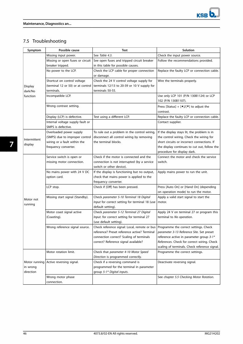
7.5 Troubleshooting
Symptom Possible cause Test Solution
Displaydark/Nofunction
Missing input power. See Table 4.3. Check the input power source.
Missing or open fuses or circuit
breaker tripped.
See open fuses and tripped circuit breaker
in this table for possible causes.
Follow the recommendations provided.
No power to the LCP. Check the LCP cable for proper connection
or damage.
Replace the faulty LCP or connection cable.
Shortcut on control voltage(terminal 12 or 50) or at controlterminals.
Check the 24 V control voltage supply forterminals 12/13 to 20-39 or 10 V supply forterminals 50-55.
Wire the terminals properly.
Incompatible LCP. Use only LCP 101 (P/N 130B1124) or LCP102 (P/N 130B1107).
Wrong contrast setting. Press [Status] + []/[] to adjust the
contrast.
Display (LCP) is defective. Test using a different LCP. Replace the faulty LCP or connection cable.
Internal voltage supply fault orSMPS is defective.
Contact supplier.
Intermittent
display
Overloaded power supply
(SMPS) due to improper controlwiring or a fault within thefrequency converter.
To rule out a problem in the control wiring,
disconnect all control wiring by removingthe terminal blocks.
If the display stays lit, the problem is in
the control wiring. Check the wiring forshort circuits or incorrect connections. Ifthe display continues to cut out, follow the
procedure for display dark.
Motor notrunning
Service switch is open or
missing motor connection.
Check if the motor is connected and the
connection is not interrupted (by a serviceswitch or other device).
Connect the motor and check the service
switch.
No mains power with 24 V DCoption card.
If the display is functioning but no output,check that mains power is applied to thefrequency converter.
Apply mains power to run the unit.
LCP stop. Check if [Off] has been pressed. Press [Auto On] or [Hand On] (dependingon operation mode) to run the motor.
Missing start signal (Standby). Check parameter 5-10 Terminal 18 DigitalInput for correct setting for terminal 18 (usedefault setting).
Apply a valid start signal to start themotor.
Motor coast signal active(Coasting).
Check parameter 5-12 Terminal 27 DigitalInput. for correct setting for terminal 27(use default setting).
Apply 24 V on terminal 27 or program thisterminal to No operation.
Wrong reference signal source. Check reference signal: Local, remote or busreference? Preset reference active? Terminalconnection correct? Scaling of terminalscorrect? Reference signal available?
Programme the correct settings. Checkparameter 3-13 Reference Site. Set presetreference active in parameter group 3-1*References. Check for correct wiring. Checkscaling of terminals. Check reference signal.
Motor runningin wrongdirection
Motor rotation limit. Check that parameter 4-10 Motor SpeedDirection is programmed correctly.
Programme the correct settings.
Active reversing signal. Check if a reversing command isprogrammed for the terminal in parametergroup 5-1* Digital inputs.
Deactivate reversing signal.
Wrong motor phase
connection.
See chapter 5.5 Checking Motor Rotation.
Maintenance, Diagnostics an...
46 4073.8/02-EN All rights reserved. MG21H202
77
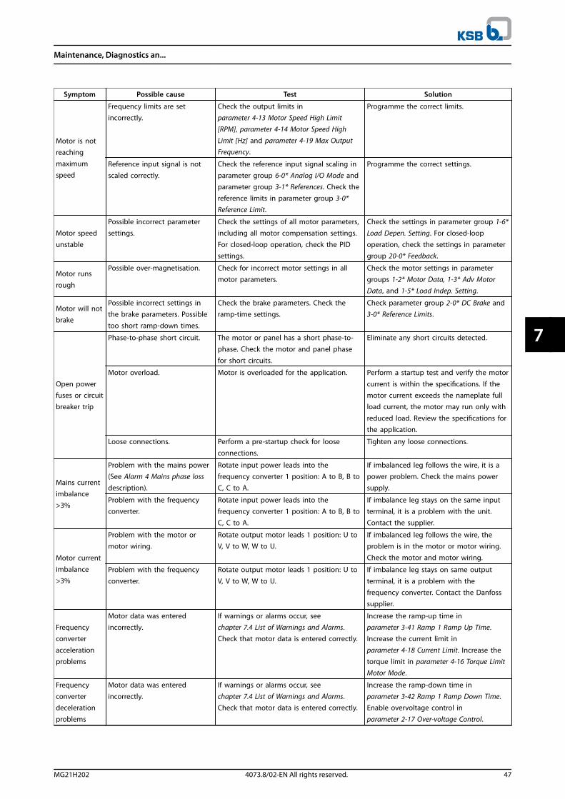
Symptom Possible cause Test Solution
Motor is notreachingmaximumspeed
Frequency limits are setincorrectly.
Check the output limits inparameter 4-13 Motor Speed High Limit[RPM], parameter 4-14 Motor Speed HighLimit [Hz] and parameter 4-19 Max OutputFrequency.
Programme the correct limits.
Reference input signal is notscaled correctly.
Check the reference input signal scaling inparameter group 6-0* Analog I/O Mode andparameter group 3-1* References. Check thereference limits in parameter group 3-0*Reference Limit.
Programme the correct settings.
Motor speedunstable
Possible incorrect parametersettings.
Check the settings of all motor parameters,including all motor compensation settings.For closed-loop operation, check the PIDsettings.
Check the settings in parameter group 1-6*Load Depen. Setting. For closed-loopoperation, check the settings in parametergroup 20-0* Feedback.
Motor runsrough
Possible over-magnetisation. Check for incorrect motor settings in allmotor parameters.
Check the motor settings in parametergroups 1-2* Motor Data, 1-3* Adv MotorData, and 1-5* Load Indep. Setting.
Motor will notbrake
Possible incorrect settings inthe brake parameters. Possibletoo short ramp-down times.
Check the brake parameters. Check theramp-time settings.
Check parameter group 2-0* DC Brake and3-0* Reference Limits.
Open powerfuses or circuitbreaker trip
Phase-to-phase short circuit. The motor or panel has a short phase-to-
phase. Check the motor and panel phasefor short circuits.
Eliminate any short circuits detected.
Motor overload. Motor is overloaded for the application. Perform a startup test and verify the motor
current is within the specifications. If themotor current exceeds the nameplate fullload current, the motor may run only with
reduced load. Review the specifications forthe application.
Loose connections. Perform a pre-startup check for looseconnections.
Tighten any loose connections.
Mains currentimbalance>3%
Problem with the mains power(See Alarm 4 Mains phase lossdescription).
Rotate input power leads into thefrequency converter 1 position: A to B, B toC, C to A.
If imbalanced leg follows the wire, it is apower problem. Check the mains powersupply.
Problem with the frequencyconverter.
Rotate input power leads into thefrequency converter 1 position: A to B, B toC, C to A.
If imbalance leg stays on the same inputterminal, it is a problem with the unit.Contact the supplier.
Motor current
imbalance>3%
Problem with the motor ormotor wiring.
Rotate output motor leads 1 position: U toV, V to W, W to U.
If imbalanced leg follows the wire, theproblem is in the motor or motor wiring.Check the motor and motor wiring.
Problem with the frequency
converter.
Rotate output motor leads 1 position: U to
V, V to W, W to U.
If imbalance leg stays on same output
terminal, it is a problem with thefrequency converter. Contact the Danfosssupplier.
Frequencyconverter
accelerationproblems
Motor data was entered
incorrectly.
If warnings or alarms occur, see
chapter 7.4 List of Warnings and Alarms.Check that motor data is entered correctly.
Increase the ramp-up time in
parameter 3-41 Ramp 1 Ramp Up Time.Increase the current limit in
parameter 4-18 Current Limit. Increase thetorque limit in parameter 4-16 Torque LimitMotor Mode.
Frequencyconverterdeceleration
problems
Motor data was entered
incorrectly.
If warnings or alarms occur, see
chapter 7.4 List of Warnings and Alarms.Check that motor data is entered correctly.
Increase the ramp-down time in
parameter 3-42 Ramp 1 Ramp Down Time.Enable overvoltage control in
parameter 2-17 Over-voltage Control.
Maintenance, Diagnostics an...
MG21H202 4073.8/02-EN All rights reserved. 47
7 7
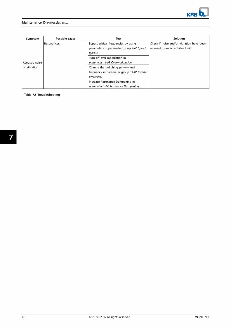
Symptom Possible cause Test Solution
Acoustic noise
or vibration
Resonances. Bypass critical frequencies by usingparameters in parameter group 4-6* SpeedBypass.
Check if noise and/or vibration have beenreduced to an acceptable limit.
Turn off over-modulation inparameter 14-03 Overmodulation.
Change the switching pattern and
frequency in parameter group 14-0* InverterSwitching.
Increase Resonance Dampening in
parameter 1-64 Resonance Dampening.
Table 7.5 Troubleshooting
Maintenance, Diagnostics an...
48 4073.8/02-EN All rights reserved. MG21H202
77
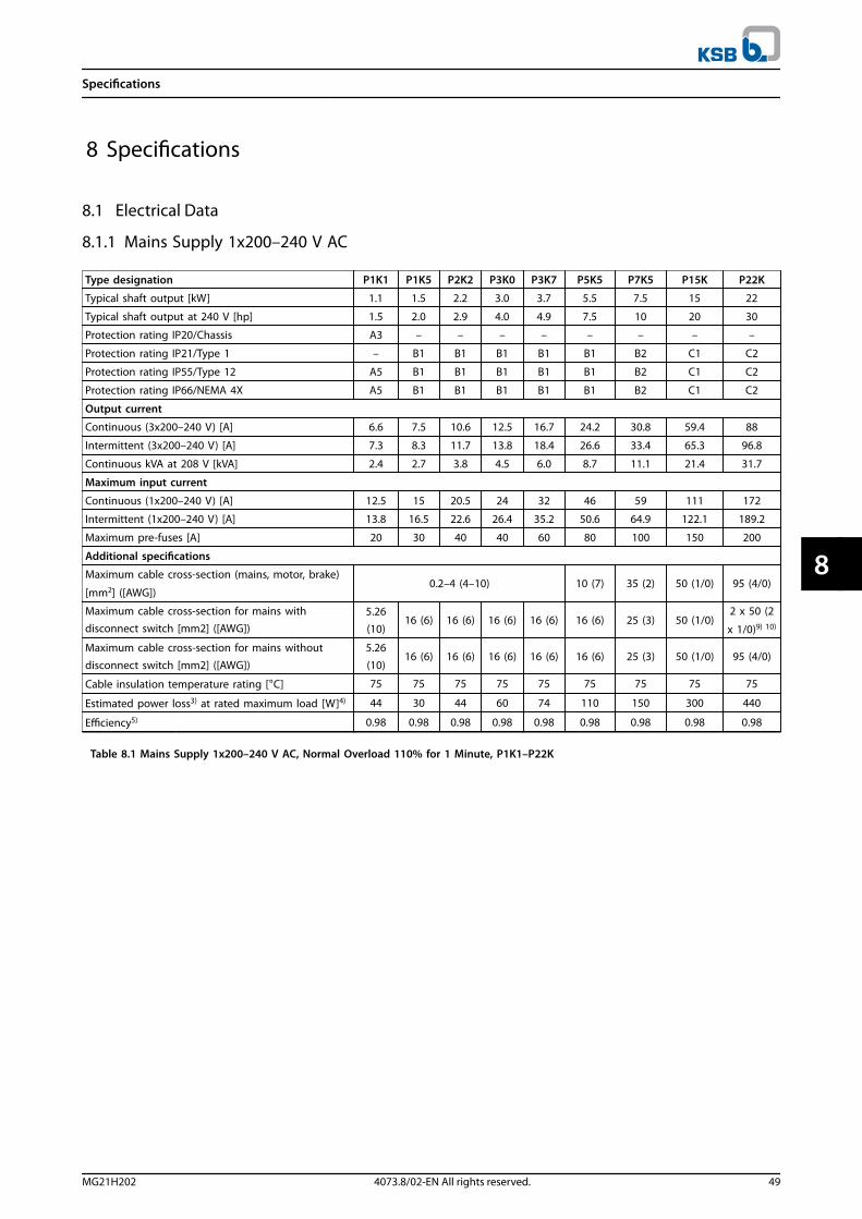
8 Specifications
8.1 Electrical Data
8.1.1 Mains Supply 1x200–240 V AC
Type designation P1K1 P1K5 P2K2 P3K0 P3K7 P5K5 P7K5 P15K P22K
Typical shaft output [kW] 1.1 1.5 2.2 3.0 3.7 5.5 7.5 15 22
Typical shaft output at 240 V [hp] 1.5 2.0 2.9 4.0 4.9 7.5 10 20 30
Protection rating IP20/Chassis A3 – – – – – – – –
Protection rating IP21/Type 1 – B1 B1 B1 B1 B1 B2 C1 C2
Protection rating IP55/Type 12 A5 B1 B1 B1 B1 B1 B2 C1 C2
Protection rating IP66/NEMA 4X A5 B1 B1 B1 B1 B1 B2 C1 C2
Output current
Continuous (3x200–240 V) [A] 6.6 7.5 10.6 12.5 16.7 24.2 30.8 59.4 88
Intermittent (3x200–240 V) [A] 7.3 8.3 11.7 13.8 18.4 26.6 33.4 65.3 96.8
Continuous kVA at 208 V [kVA] 2.4 2.7 3.8 4.5 6.0 8.7 11.1 21.4 31.7
Maximum input current
Continuous (1x200–240 V) [A] 12.5 15 20.5 24 32 46 59 111 172
Intermittent (1x200–240 V) [A] 13.8 16.5 22.6 26.4 35.2 50.6 64.9 122.1 189.2
Maximum pre-fuses [A] 20 30 40 40 60 80 100 150 200
Additional specifications
Maximum cable cross-section (mains, motor, brake)
[mm2] ([AWG])0.2–4 (4–10) 10 (7) 35 (2) 50 (1/0) 95 (4/0)
Maximum cable cross-section for mains withdisconnect switch [mm2] ([AWG])
5.26
(10)16 (6) 16 (6) 16 (6) 16 (6) 16 (6) 25 (3) 50 (1/0)
2 x 50 (2
x 1/0)9) 10)
Maximum cable cross-section for mains without
disconnect switch [mm2] ([AWG])
5.26
(10)16 (6) 16 (6) 16 (6) 16 (6) 16 (6) 25 (3) 50 (1/0) 95 (4/0)
Cable insulation temperature rating [°C] 75 75 75 75 75 75 75 75 75
Estimated power loss3) at rated maximum load [W]4) 44 30 44 60 74 110 150 300 440
Efficiency5) 0.98 0.98 0.98 0.98 0.98 0.98 0.98 0.98 0.98
Table 8.1 Mains Supply 1x200–240 V AC, Normal Overload 110% for 1 Minute, P1K1–P22K
Specifications
MG21H202 4073.8/02-EN All rights reserved. 49
8 8

8.1.2 Mains Supply 3x200–240 V AC
Type designation PK25 PK37 PK55 PK75
High/normal overload1) HO NO HO NO HO NO HO NO
Typical shaft output [kW] 0.25 0.37 0.55 0.75
Typical shaft output at 208 V [hp] 0.34 0.5 0.75 1
Protection rating IP20/Chassis6)
Protection rating IP21/Type 1A2 A2 A2 A2
Protection rating IP55/Type 12Protection rating IP66/NEMA 4X
A4/A5 A4/A5 A4/A5 A4/A5
Output current
Continuous (3x200–240 V) [A] 1.8 2.4 3.5 4.6
Intermittent (3x200–240 V) [A] 2.7 2.0 3.6 2.6 5.3 3.9 6.9 5.1
Continuous kVA at 208 V [kVA] 0.65 0.86 1.26 1.66
Maximum input current
Continuous (3x200–240 V) [A] 1.6 2.2 3.2 4.1
Intermittent (3x200–240 V) [A] 2.4 1.8 3.3 2.4 4.8 3.5 6.2 4.5
Maximum pre-fuses [A] 10 10 10 10
Additional specifications
Maximum cable cross-section2) for mains, motor, brake,
and load sharing [mm2] ([AWG])
4, 4, 4 (12, 12, 12)
(minimum 0.2 (24))
Maximum cable cross-section2) for mains disconnect
[mm2] ([AWG])6, 4, 4 (10, 12, 12)
Estimated power loss3) at rated maximum load [W]4) 21 29 42 54
Efficiency5) 0.94 0.94 0.95 0.95
Table 8.2 Mains Supply 3x200–240 V AC, PK25–PK75
Type designation P1K1 P1K5 P2K2 P3K0 P3K7
High/normal overload1) HO NO HO NO HO NO HO NO HO NO
Typical shaft output [kW] 1.1 1.5 2.2 3.0 3.7
Typical shaft output at 208 V [hp] 1.5 2 3 4 5
Protection rating IP20/Chassis6)
Protection rating IP21/Type 1A2 A2 A2 A3 A3
Protection rating IP55/Type 12Protection rating IP66/NEMA 4X
A4/A5 A4/A5 A4/A5 A5 A5
Output current
Continuous (3x200–240 V) [A] 6.6 7.5 10.6 12.5 16.7
Intermittent (3x200–240 V) [A] 9.9 7.3 11.3 8.3 15.9 11.7 18.8 13.8 25 18.4
Continuous kVA at 208 V [kVA] 2.38 2.70 3.82 4.50 6.00
Maximum input current
Continuous (3x200–240 V) [A] 5.9 6.8 9.5 11.3 15.0
Intermittent (3x200–240 V) [A] 8.9 6.5 10.2 7.5 14.3 10.5 17.0 12.4 22.5 16.5
Maximum pre-fuses [A] 20 20 20 32 32
Additional specifications
Maximum cable cross-section2) for mains, motor,
brake, and load sharing [mm2] ([AWG])
4, 4, 4 (12, 12, 12)
(minimum 0.2 (24))
Maximum cable cross-section2) for mains disconnect
[mm2] [(AWG)]6, 4, 4 (10, 12, 12)
Estimated power loss3) at rated maximum load [W]4) 63 82 116 155 185
Efficiency5) 0.96 0.96 0.96 0.96 0.96
Table 8.3 Mains Supply 3x200–240 V AC, P1K1–P3K7
Specifications
50 4073.8/02-EN All rights reserved. MG21H202
88

Type designation P5K5 P7K5 P11K P15K
High/normal overload1) HO NO HO NO HO NO HO NO
Typical shaft output [kW] 3.7 5.5 5.5 7.5 7.5 11 11 15
Typical shaft output at 208 V [hp] 5.0 7.5 7.5 10 10 15 15 20
IP20/Chassis7) B3 B3 B3 B4
Protection rating IP21/Type 1Protection rating IP55/Type 12Protection rating IP66/NEMA 4X
B1 B1 B1 B2
Output current
Continuous (3x200–240 V) [A] 16.7 24.2 24.2 30.8 30.8 46.2 46.2 59.4
Intermittent (3x200–240 V) [A] 26.7 26.6 38.7 33.9 49.3 50.8 73.9 65.3
Continuous kVA at 208 V [kVA] 6.0 8.7 8.7 11.1 11.1 16.6 16.6 21.4
Maximum input current
Continuous (3x200–240 V) [A] 15.0 22.0 22.0 28.0 28.0 42.0 42.0 54.0
Intermittent (3x200–240 V) [A] 24.0 24.2 35.2 30.8 44.8 46.2 67.2 59.4
Maximum pre-fuses [A] 63 63 63 80
Additional specifications
IP20 maximum cable cross-section2) for mains, brake,
motor, and load sharing [mm2] ([AWG]) 10, 10, – (8, 8, –) 10, 10, – (8, 8, –) 10, 10, – (8, 8, –) 35, –, – (2, –, –)
Protection rating IP21 maximum cable cross-section2)
for mains, brake, and load sharing [mm2] ([AWG])16, 10, 16 (6, 8, 6) 16, 10, 16 (6, 8, 6) 16, 10, 16 (6, 8, 6) 35, –, – (2, –, –)
Protection rating IP21 maximum cable cross-section2)
for motor
[mm2] ([AWG])
10, 10, – (8, 8, –) 10, 10, – (8, 8, –) 10, 10, – (8, 8, –) 35, 25, 25 (2, 4, 4)
Maximum cable cross-section2) for mains disconnect
[mm2] ([AWG])16, 10, 10 (6, 8, 8) 35 (2)
Estimated power loss3) at rated maximum load [W]4) 239 310 239 310 371 514 463 602
Efficiency5) 0.96 0.96 0.96 0.96
Table 8.4 Mains Supply 3x200–240 V AC, P5K5–P15K
Specifications
MG21H202 4073.8/02-EN All rights reserved. 51
8 8
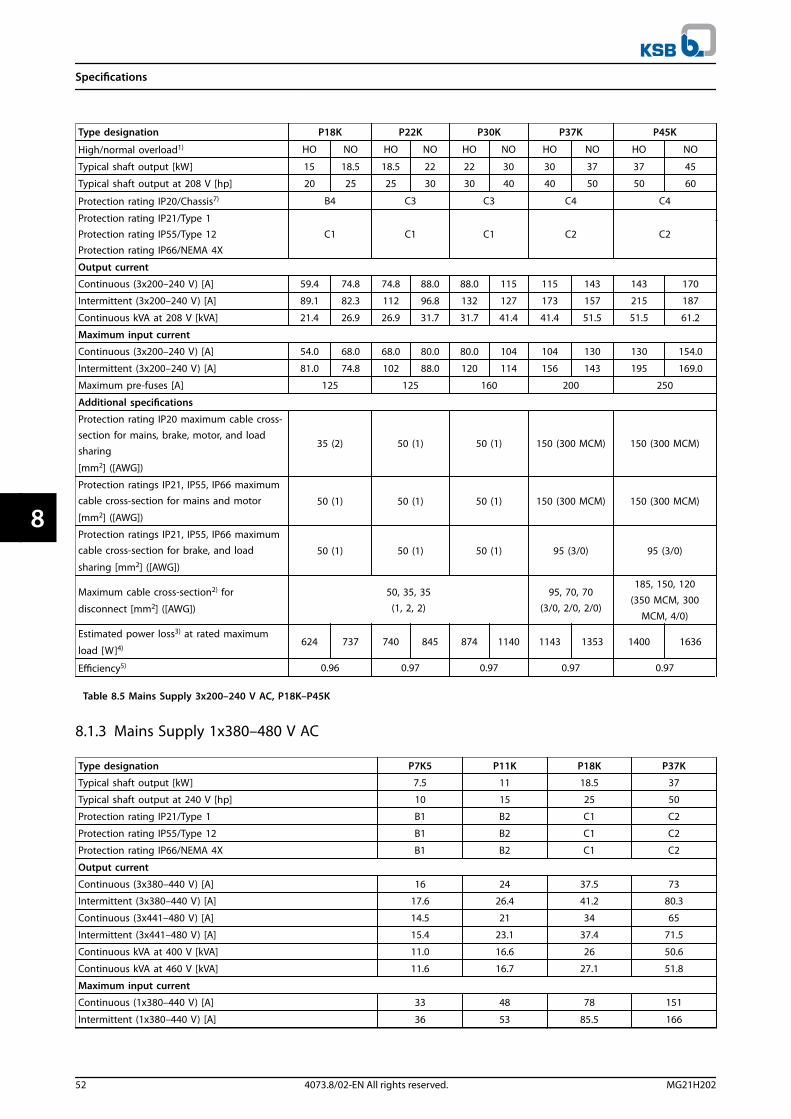
Type designation P18K P22K P30K P37K P45K
High/normal overload1) HO NO HO NO HO NO HO NO HO NO
Typical shaft output [kW] 15 18.5 18.5 22 22 30 30 37 37 45
Typical shaft output at 208 V [hp] 20 25 25 30 30 40 40 50 50 60
Protection rating IP20/Chassis7) B4 C3 C3 C4 C4
Protection rating IP21/Type 1Protection rating IP55/Type 12Protection rating IP66/NEMA 4X
C1 C1 C1 C2 C2
Output current
Continuous (3x200–240 V) [A] 59.4 74.8 74.8 88.0 88.0 115 115 143 143 170
Intermittent (3x200–240 V) [A] 89.1 82.3 112 96.8 132 127 173 157 215 187
Continuous kVA at 208 V [kVA] 21.4 26.9 26.9 31.7 31.7 41.4 41.4 51.5 51.5 61.2
Maximum input current
Continuous (3x200–240 V) [A] 54.0 68.0 68.0 80.0 80.0 104 104 130 130 154.0
Intermittent (3x200–240 V) [A] 81.0 74.8 102 88.0 120 114 156 143 195 169.0
Maximum pre-fuses [A] 125 125 160 200 250
Additional specifications
Protection rating IP20 maximum cable cross-section for mains, brake, motor, and loadsharing
[mm2] ([AWG])
35 (2) 50 (1) 50 (1) 150 (300 MCM) 150 (300 MCM)
Protection ratings IP21, IP55, IP66 maximumcable cross-section for mains and motor
[mm2] ([AWG])
50 (1) 50 (1) 50 (1) 150 (300 MCM) 150 (300 MCM)
Protection ratings IP21, IP55, IP66 maximumcable cross-section for brake, and load
sharing [mm2] ([AWG])
50 (1) 50 (1) 50 (1) 95 (3/0) 95 (3/0)
Maximum cable cross-section2) for
disconnect [mm2] ([AWG])
50, 35, 35(1, 2, 2)
95, 70, 70(3/0, 2/0, 2/0)
185, 150, 120
(350 MCM, 300MCM, 4/0)
Estimated power loss3) at rated maximum
load [W]4)624 737 740 845 874 1140 1143 1353 1400 1636
Efficiency5) 0.96 0.97 0.97 0.97 0.97
Table 8.5 Mains Supply 3x200–240 V AC, P18K–P45K
8.1.3 Mains Supply 1x380–480 V AC
Type designation P7K5 P11K P18K P37K
Typical shaft output [kW] 7.5 11 18.5 37
Typical shaft output at 240 V [hp] 10 15 25 50
Protection rating IP21/Type 1 B1 B2 C1 C2
Protection rating IP55/Type 12 B1 B2 C1 C2
Protection rating IP66/NEMA 4X B1 B2 C1 C2
Output current
Continuous (3x380–440 V) [A] 16 24 37.5 73
Intermittent (3x380–440 V) [A] 17.6 26.4 41.2 80.3
Continuous (3x441–480 V) [A] 14.5 21 34 65
Intermittent (3x441–480 V) [A] 15.4 23.1 37.4 71.5
Continuous kVA at 400 V [kVA] 11.0 16.6 26 50.6
Continuous kVA at 460 V [kVA] 11.6 16.7 27.1 51.8
Maximum input current
Continuous (1x380–440 V) [A] 33 48 78 151
Intermittent (1x380–440 V) [A] 36 53 85.5 166
Specifications
52 4073.8/02-EN All rights reserved. MG21H202
88

Type designation P7K5 P11K P18K P37K
Continuous (1x441–480 V) [A] 30 41 72 135
Intermittent (1x441–480 V) [A] 33 46 79.2 148
Maximum pre-fuses [A] 63 80 160 250
Additional specifications
Maximum cable cross-section for mains, motor, and brake
[mm2]] ([AWG])10 (7) 35 (2) 50 (1/0) 120 (4/0)
Estimated power loss3) at rated maximum load [W]4) 300 440 740 1480
Efficiency5) 0.96 0.96 0.96 0.96
Table 8.6 Mains Supply 1x380–480 V AC, Normal Overload 110% for 1 Minute, P7K5–P37K
8.1.4 Mains Supply 3x380–480 V AC
Type designation PK37 PK55 PK75 P1K1 P1K5
High/normal overload1) HO NO HO NO HO NO HO NO HO NO
Typical shaft output [kW] 0.37 0.55 0.75 1.1 1.5
Typical shaft output at 460 V [hp] 0.5 0.75 1.0 1.5 2.0
Protection rating IP20/Chassis6) A2 A2 A2 A2 A2
Protection rating IP55/Type 12Protection rating IP66/NEMA 4X
A4/A5 A4/A5 A4/A5 A4/A5 A4/A5
Output current
Continuous (3x380–440 V) [A] 1.3 1.8 2.4 3.0 4.1
Intermittent (3x380–440 V) [A] 2.0 1.4 2.7 2.0 3.6 2.6 4.5 3.3 6.2 4.5
Continuous (3x441–480 V) [A] 1.2 1.6 2.1 2.7 3.4
Intermittent (3x441–480 V) [A] 1.8 1.3 2.4 1.8 3.2 2.3 4.1 3.0 5.1 3.7
Continuous kVA at 400 V [kVA] 0.9 1.3 1.7 2.1 2.8
Continuous kVA at 460 V [kVA] 0.9 1.3 1.7 2.4 2.7
Maximum input current
Continuous (3x380–440 V) [A] 1.2 1.6 2.2 2.7 3.7
Intermittent (3x380–440 V) [A] 1.8 1.3 2.4 1.8 3.3 2.4 4.1 3.0 5.6 4.1
Continuous (3x441–480 V) [A] 1.0 1.4 1.9 2.7 3.1
Intermittent (3x441–480 V) [A] 1.5 1.1 2.1 1.5 2.9 2.1 4.1 3.0 4.7 3.4
Maximum pre-fuses [A] 10 10 10 10 10
Additional specifications
Protection ratings IP20, IP21
maximum cable cross-section2) formains, motor, brake, and load
sharing [mm2] ([AWG])
4, 4, 4 (12, 12, 12)(minimum 0.2 (24))
Protection ratings IP55, IP66
maximum cable cross-section2) formains, motor, brake, and load
sharing [mm2] ([AWG])
4, 4, 4 (12, 12, 12)
Maximum cable cross-section2) for
disconnect [mm2] ([AWG])6, 4, 4 (10, 12, 12)
Estimated power loss3)
at rated maximum load [W]4)35 42 46 58 62
Efficiency5) 0.93 0.95 0.96 0.96 0.97
Table 8.7 Mains Supply 3x380–480 V AC, PK37–P1K5
Specifications
MG21H202 4073.8/02-EN All rights reserved. 53
8 8

Type designation P2K2 P3K0 P4K0 P5K5 P7K5
High/normal overload1) HO NO HO NO HO NO HO NO HO NO
Typical shaft output [kW] 2.2 3.0 4.0 5.5 7.5
Typical shaft output at 460 V [hp] 2.9 4.0 5.3 7.5 10
Protection rating IP20/Chassis6) A2 A2 A2 A3 A3
Protection rating IP55/Type 12Protection rating IP66/NEMA 4X
A4/A5 A4/A5 A4/A5 A5 A5
Output current
Continuous (3x380–440 V) [A] 5.6 7.2 10 13 16
Intermittent (3x380–440 V) [A] 8.4 6.2 10.8 7.9 15.0 11.0 19.5 14.3 24.0 17.6
Continuous (3x441–480 V) [A] 4.8 6.3 8.2 11 14.5
Intermittent (3x441–480 V) [A] 7.2 5.3 9.5 6.9 12.3 9.0 16.5 12.1 21.8 16.0
Continuous kVA at 400 V [kVA] 3.9 5.0 6.9 9.0 11.0
Continuous kVA at 460 V [kVA] 3.8 5.0 6.5 8.8 11.6
Maximum input current
Continuous (3x380–440 V) [A] 5.0 6.5 9.0 11.7 14.4
Intermittent (3x380–440 V) [A] 7.5 5.5 9.8 7.2 13.5 9.9 17.6 12.9 21.6 15.8
Continuous(3x441–480 V) [A] 4.3 5.7 7.4 9.9 13.0
Intermittent (3x441–480 V) [A] 6.5 4.7 8.6 6.3 11.1 8.1 14.9 10.9 19.5 14.3
Maximum pre-fuses [A] 20 20 20 30 30
Additional specifications
Protection ratings IP20, IP21
maximum cable cross-section2) formains, motor, brake, and load
sharing [mm2] ([AWG])
4, 4, 4 (12, 12, 12)(minimum 0.2 (24))
Protection ratings IP55, IP66
maximum cable cross-section2) formains, motor, brake, and load
sharing [mm2] ([AWG])
4, 4, 4 (12, 12, 12)
Maximum cable cross-section2) for
disconnect [mm2] ([AWG])6, 4, 4 (10, 12, 12)
Estimated power loss3)
at rated maximum load [W]4)88 116 124 187 225
Efficiency5) 0.97 0.97 0.97 0.97 0.97
Table 8.8 Mains Supply 3x380–480 V AC, P2K2–P7K5
Specifications
54 4073.8/02-EN All rights reserved. MG21H202
88

Type designation P11K P15K P18K P22K P30K
High/normal overload1) HO NO HO NO HO NO HO NO HO NO
Typical shaft output [kW] 7.5 11 11 15 15 18.5 22.0 22.0 22.0 30
Typical shaft output at 460 V [hp] 10 15 15 20 20 25 30 30 30 40
Protection rating IP20/Chassis7) B3 B3 B3 B4 B4
Protection rating IP21/Type 1 B1 B1 B1 B2 B2
Protection rating IP55/Type 12
Protection rating IP66/NEMA 4XB1 B1 B1 B2 B2
Output current
Continuous (3x380–440 V) [A] – 24 24 32 32 37.5 37.5 44 44 61
Intermittent (60 s overload)(3x380–440 V) [A]
– 26.4 38.4 35.2 51.2 41.3 60 48.4 70.4 67.1
Continuous (3x441–480 V) [A] – 21 21 27 27 34 34 40 40 52
Intermittent (60 s overload)
(3x441–480 V) [A]– 23.1 33.6 29.7 43.2 37.4 54.4 44 64 61.6
Continuous kVA at 400 V [kVA] – 16.6 16.6 22.2 22.2 26 26 30.5 30.5 42.3
Continuous kVA at 460 V [kVA] – 16.7 16.7 21.5 21.5 27.1 27.1 31.9 31.9 41.4
Maximum input current
Continuous (3x380–440 V) [A] – 22 22 29 29 34 34 40 40 55
Intermittent (60 s overload)(3x380–440 V) [A]
– 24.2 35.2 31.9 46.4 37.4 54.4 44 64 60.5
Continuous (3x441–480 V) [A] – 19 19 25 25 31 31 36 36 47
Intermittent (60 s overload)(3x441–480 V) [A]
– 20.9 30.4 27.5 40 34.1 49.6 39.6 57.6 51.7
Maximum pre-fuses [A] – 63 63 63 63 80
Additional specifications
Protection ratings IP21, IP55, IP66
maximum cable cross-section2) formains, brake, and load sharing
[mm2] ([AWG])
16, 10, 16 (6, 8, 6) 35, –, – (2, –, –)
Protection ratings IP21, IP55, IP66
maximum cable cross-section2) for
motor [mm2] ([AWG])
10, 10,– (8, 8,–) 35, 25, 25 (2, 4, 4)
Protection rating IP20 maximum
cable cross-section2) for mains,brake, motor, and load sharing
[mm2] ([AWG])
10, 10,– (8, 8,–) 35, –, – (2, –, –)
Maximum cable cross-section2) for
disconnect [mm2] ([AWG])16, 10, 10 (6, 8, 8)
Estimated power loss3)
at rated maximum load [W]4)291 392 291 392 379 465 444 525 547 739
Efficiency5) 0.98 0.98 0.98 0.98 0.98
Table 8.9 Mains Supply 3x380–480 V AC, P11K–P30K
Specifications
MG21H202 4073.8/02-EN All rights reserved. 55
8 8

Type designation P37K P45K P55K P75K P90K
High/normal overload1) HO NO HO NO HO NO HO NO HO NO
Typical shaft output [kW] 30 37 37 45 45 55 55 75 75 90
Typical shaft output at 460 V [hp] 40 50 50 60 60 75 75 100 100 125
Protection rating IP20/Chassis6) B4 C3 C3 C4 C4
Protection rating IP21/Type 1 C1 C1 C1 C2 C2
Protection rating IP55/Type 12
Protection rating IP66/NEMA 4XC1 C1 C1 C2 C2
Output current
Continuous (3x380–440 V) [A] 61 73 73 90 90 106 106 147 147 177
Intermittent (60 s overload) (3x380–440 V) [A]
91.5 80.3 110 99 135 117 159 162 221 195
Continuous (3x441–480 V) [A] 52 65 65 80 80 105 105 130 130 160
Intermittent (60 s overload) (3x441–
480 V) [A]78 71.5 97.5 88 120 116 158 143 195 176
Continuous kVA at 400 V [kVA] 42.3 50.6 50.6 62.4 62.4 73.4 73.4 102 102 123
Continuous kVA at 460 V [kVA] 41.4 51.8 51.8 63.7 63.7 83.7 83.7 104 103.6 128
Maximum input current
Continuous (3x380–440 V) [A] 55 66 66 82 82 96 96 133 133 161
Intermittent (60 s overload) (3x380–440 V) [A]
82.5 72.6 99 90.2 123 106 144 146 200 177
Continuous (3x441–480 V) [A] 47 59 59 73 73 95 95 118 118 145
Intermittent (60 s overload) (3x441–480 V) [A]
70.5 64.9 88.5 80.3 110 105 143 130 177 160
Maximum pre-fuses [A] 100 125 160 250 250
Additional specifications
Protection rating IP20 maximumcable cross-section for mains and
motor [mm2] ([AWG])
35 (2) 50 (1) 50 (1) 150 (300 MCM) 150 (300 MCM)
Protection rating IP20 maximumcable cross-section for brake andload sharing
[mm2] ([AWG])
35 (2) 50 (1) 50 (1) 95 (4/0) 95 (4/0)
Protection ratings IP21, IP55, IP66maximum cable cross-section formains and motor
[mm2] ([AWG])
50 (1) 50 (1) 50 (1) 150 (300 MCM) 150 (300 MCM)
Protection ratings IP21, IP55, IP66
maximum cable cross-section for
brake and load sharing [mm2]([AWG])
50 (1) 50 (1) 50 (1) 95 (3/0) 95 (3/0)
Maximum cable cross-section2) formains disconnect
[mm2] ([AWG])
50, 35, 35(1, 2, 2)
95, 70, 70(3/0, 2/0, 2/0)
185, 150, 120(350 MCM, 300
MCM, 4/0)
Estimated power loss3)
at rated maximum load [W]4)570 698 697 843 891 1083 1022 1384 1232 1474
Efficiency5) 0.98 0.98 0.98 0.98 0.99
Table 8.10 Mains Supply 3x380–480 V AC, P37K–P90K
Specifications
56 4073.8/02-EN All rights reserved. MG21H202
88

8.1.5 Mains Supply 3x525–600 V AC
Type designation PK75 P1K1 P1K5 P2K2
High/normal overload1) HO NO HO NO HO NO HO NO
Typical shaft output [kW] 0.75 1.1 1.5 2.2
Typical shaft output [hp] 1 1.5 2 3
Protection rating IP20/ChassisProtection rating IP21/Type 1
A3 A3 A3 A3
Protection rating IP55/Type 12 A5 A5 A5 A5
Output current
Continuous (3x525–550 V) [A] 1.8 2.6 2.9 4.1
Intermittent (3x525–550 V) [A] 2.7 2.0 3.9 2.9 4.4 3.2 6.2 4.5
Continuous (3x551–600 V) [A] 1.7 2.4 2.7 3.9
Intermittent (3x551–600 V) [A] 2.6 1.9 3.6 2.6 4.1 3.0 5.9 4.3
Continuous kVA at 550 V [kVA] 1.7 2.5 2.8 3.9
Continuous kVA at 550 V [kVA] 1.7 2.4 2.7 3.9
Maximum input current
Continuous (3x525–600 V) [A] 1.7 2.4 2.7 4.1
Intermittent (3x525–600 V) [A] 2.6 1.9 3.6 2.6 4.1 3.0 6.2 4.5
Maximum pre-fuses [A] 10 10 10 20
Additional specifications
Maximum cable cross-section2) for
mains, motor, brake, and load sharing
[mm2] ([AWG])
4,4,4 (12,12,12)(minimum 0.2 (24))
Maximum cable cross-section2) for
mains disconnect [mm2] ([AWG])6,4,4 (10,12,12)
Estimated power loss3)
at rated maximum load [W]4)35 50 65 92
Efficiency5) 0.97 0.97 0.97 0.97
Table 8.11 Mains Supply 3x525–600 V AC, PK75–P2K2
Specifications
MG21H202 4073.8/02-EN All rights reserved. 57
8 8
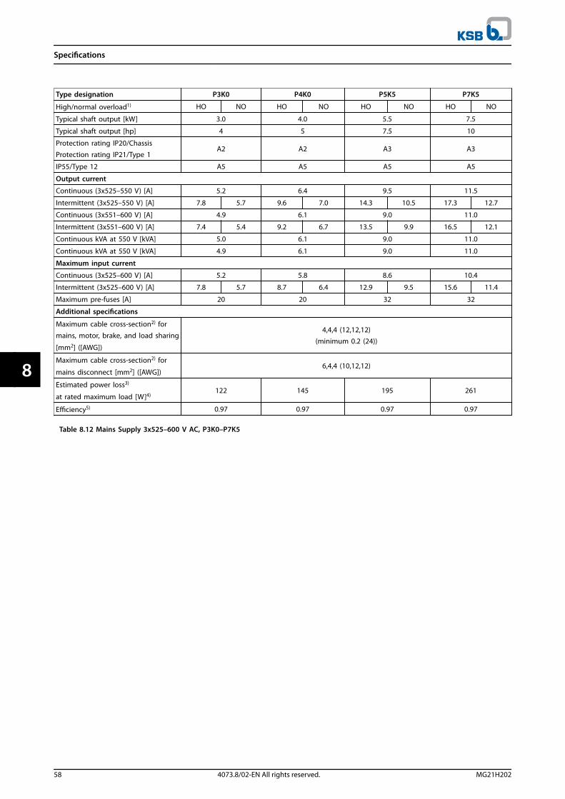
Type designation P3K0 P4K0 P5K5 P7K5
High/normal overload1) HO NO HO NO HO NO HO NO
Typical shaft output [kW] 3.0 4.0 5.5 7.5
Typical shaft output [hp] 4 5 7.5 10
Protection rating IP20/Chassis
Protection rating IP21/Type 1A2 A2 A3 A3
IP55/Type 12 A5 A5 A5 A5
Output current
Continuous (3x525–550 V) [A] 5.2 6.4 9.5 11.5
Intermittent (3x525–550 V) [A] 7.8 5.7 9.6 7.0 14.3 10.5 17.3 12.7
Continuous (3x551–600 V) [A] 4.9 6.1 9.0 11.0
Intermittent (3x551–600 V) [A] 7.4 5.4 9.2 6.7 13.5 9.9 16.5 12.1
Continuous kVA at 550 V [kVA] 5.0 6.1 9.0 11.0
Continuous kVA at 550 V [kVA] 4.9 6.1 9.0 11.0
Maximum input current
Continuous (3x525–600 V) [A] 5.2 5.8 8.6 10.4
Intermittent (3x525–600 V) [A] 7.8 5.7 8.7 6.4 12.9 9.5 15.6 11.4
Maximum pre-fuses [A] 20 20 32 32
Additional specifications
Maximum cable cross-section2) for
mains, motor, brake, and load sharing
[mm2] ([AWG])
4,4,4 (12,12,12)(minimum 0.2 (24))
Maximum cable cross-section2) for
mains disconnect [mm2] ([AWG])6,4,4 (10,12,12)
Estimated power loss3)
at rated maximum load [W]4)122 145 195 261
Efficiency5) 0.97 0.97 0.97 0.97
Table 8.12 Mains Supply 3x525–600 V AC, P3K0–P7K5
Specifications
58 4073.8/02-EN All rights reserved. MG21H202
88

Type designation P11K P15K P18K P22K P30K P37K
High/normal overload1) HO NO HO NO HO NO HO NO HO NO HO NO
Typical shaft output [kW] 7.5 11 11 15 15 18.5 18.5 22 22 30 30 37
Typical shaft output [hp] 10 15 15 20 20 25 25 30 30 40 40 50
Protection rating IP20/
ChassisB3 B3 B3 B4 B4 B4
Protection rating IP21/
Type 1Protection rating IP55/Type 12
Protection rating IP66/NEMA 4X
B1 B1 B1 B2 B2 C1
Output current
Continuous (3x525–550 V)[A]
11.5 19 19 23 23 28 28 36 36 43 43 54
Intermittent (3x525–550V) [A]
18.4 21 30 25 37 31 45 40 58 47 65 59
Continuous (3x551–600 V)
[A]11 18 18 22 22 27 27 34 34 41 41 52
Intermittent (3x551–600
V) [A]17.6 20 29 24 35 30 43 37 54 45 62 57
Continuous kVA at 550 V[kVA]
11 18.1 18.1 21.9 21.9 26.7 26.7 34.3 34.3 41.0 41.0 51.4
Continuous kVA at 575 V[kVA]
11 17.9 17.9 21.9 21.9 26.9 26.9 33.9 33.9 40.8 40.8 51.8
Maximum input current
Continuous at 550 V [A] 10.4 17.2 17.2 20.9 20.9 25.4 25.4 32.7 32.7 39 39 49
Intermittent at 550 V [A] 16.6 19 28 23 33 28 41 36 52 43 59 54
Continuous at 575 V [A] 9.8 16 16 20 20 24 24 31 31 37 37 47
Intermittent at 575 V [A] 15.5 17.6 26 22 32 27 39 34 50 41 56 52
Maximum pre-fuses [A] 40 40 50 60 80 100
Additional specifications
Protection rating IP20,
maximum cable cross-
section2) for mains, brake,motor, and load sharing
[mm2] ([AWG])
10, 10,–(8, 8,–)
35,–,–(2,–,–)
Protection ratings IP21,IP55, IP66 maximum cable
cross-section2) for mains,brake, and load sharing
[mm2] ([AWG])
16, 10, 10
(6, 8, 8)
35,–,–
(2,–,–)
Protection ratings IP21,IP55, IP66 maximum cable
cross-section2) for motor
[mm2] ([AWG])
10, 10,–(8, 8,–)
35, 25, 25(2, 4, 4)
Maximum cable cross-
section2) for mains
disconnect [mm2] ([AWG])
16, 10, 10(6, 8, 8)
50, 35, 35(1, 2, 2)
Estimated power loss3)
at rated maximum load
[W]4)
220 300 220 300 300 370 370 440 440 600 600 740
Efficiency5) 0.98 0.98 0.98 0.98 0.98 0.98
Table 8.13 Mains supply 3x525–600 V AC, P11K–P37K
Specifications
MG21H202 4073.8/02-EN All rights reserved. 59
8 8

Type designation P45K P55K P75K P90K
High/normal overload1) HO NO HO NO HO NO HO NO
Typical shaft output [kW] 37 45 45 55 55 75 75 90
Typical shaft output [hp] 50 60 60 75 75 100 100 125
Protection rating IP20/Chassis C3 C3 C4 C4
Protection rating IP21/Type 1
Protection rating IP55/Type 12Protection rating IP66/NEMA 4X
C1 C1 C2 C2
Output current
Continuous (3x525–550 V) [A] 54 65 65 87 87 105 105 137
Intermittent (3x525–550 V) [A] 81 72 98 96 131 116 158 151
Continuous (3x525–600 V) [A] 52 62 62 83 83 100 100 131
Intermittent (3x525–600 V) [A] 78 68 93 91 125 110 150 144
Continuous kVA at 525 V [kVA] 51.4 61.9 61.9 82.9 82.9 100 100.0 130.5
Continuous kVA at 575 V [kVA] 51.8 61.7 61.7 82.7 82.7 99.6 99.6 130.5
Maximum input current
Continuous at 550 V [A] 49 59 59 78.9 78.9 95.3 95.3 124.3
Intermittent at 550 V [A] 74 65 89 87 118 105 143 137
Continuous at 575 V [A] 47 56 56 75 75 91 91 119
Intermittent at 575 V [A] 70 62 85 83 113 100 137 131
Maximum pre-fuses [A] 150 160 225 250
Additional specifications
Protection rating IP20 maximum cable
cross-section for mains and motor
[mm2] ([AWG])
50 (1) 150 (300 MCM)
Protection rating IP20 maximum cablecross-section for brake and load
sharing [mm2] ([AWG])
50 (1) 95 (4/0)
Protection ratings IP21, IP55, IP66maximum cable cross-section formains and motor
[mm2] ([AWG])
50 (1) 150 (300 MCM)
Protection ratings IP21, IP55, IP66maximum cable cross-section for
brake and load sharing [mm2] ([AWG])
50 (1) 95 (4/0)
Maximum cable cross-section2) for
mains disconnect [mm2] ([AWG])
50, 35, 35(1, 2, 2)
95, 70, 70(3/0, 2/0, 2/0)
185, 150, 120
(350 MCM, 300 MCM,4/0)
Estimated power loss3)
at rated maximum load [W]4)740 900 900 1100 1100 1500 1500 1800
Efficiency5) 0.98 0.98 0.98 0.98
Table 8.14 Mains supply 3x525–600 V AC, P45K–P90K
Specifications
60 4073.8/02-EN All rights reserved. MG21H202
88

8.1.6 Mains Supply 3x525–690 V AC
Type designation P1K1 P1K5 P2K2 P3K0 P4K0 P5K5 P7K5
High/normal overload1) HO NO HO NO HO NO HO NO HO NO HO NO HO NO
Typical shaft output [kW] 1.1 1.5 2.2 3.0 4.0 5.5 7.5
Typical shaft output [hp] 1.5 2 3 4 5 7.5 10
IP20/Chassis A3 A3 A3 A3 A3 A3 A3
Output current
Continuous (3x525–550 V) [A] 2.1 2.7 3.9 4.9 6.1 9.0 11.0
Intermittent (3x525–550 V) [A] 3.2 2.3 4.1 3.0 5.9 4.3 7.4 5.4 9.2 6.7 13.5 9.9 16.5 12.1
Continuous (3x551–690 V) [A] 1.6 2.2 3.2 4.5 5.5 7.5 10.0
Intermittent (3x551–690 V) [A] 2.4 1.8 3.3 2.4 4.8 3.5 6.8 5.0 8.3 6.1 11.3 8.3 15.0 11.0
Continuous kVA at 525 V [kVA] 1.9 2.5 3.5 4.5 5.5 8.2 10.0
Continuous kVA at 690 V [kVA] 1.9 2.6 3.8 5.4 6.6 9.0 12.0
Maximum input current
Continuous (3x525–550 V) [A] 1.9 2.4 3.5 4.4 5.5 8.1 9.9
Intermittent (3x525–550 V) [A] 2.9 2.1 3.6 2.6 5.3 3.9 6.6 4.8 8.3 6.1 12.2 8.9 14.9 10.9
Continuous (3x551–690 V) [A] 1.4 2.0 2.9 4.0 4.9 6.7 9.0
Intermittent (3x551–690 V) [A] 2.1 1.5 3.0 2.2 4.4 3.2 6.0 4.4 7.4 5.4 10.1 7.4 13.5 9.9
Additional specifications
Maximum cable cross–section2)
for mains, motor, brake, and load
sharing [mm2] ([AWG])
4, 4, 4(12, 12, 12)
(min. 0.2 (24)
Maximum cable cross–section2)
for mains disconnect
[mm2] ([AWG])
6, 4, 4(10, 12, 12)
Estimated power loss3)
at rated maximum load [W]4) 44 60 88 120 160 220 300
Efficiency5) 0.96 0.96 0.96 0.96 0.96 0.96 0.96
Table 8.15 A3 Enclosure, Mains Supply 3x525–690 V AC IP20/Protected Chassis, P1K1–P7K5
Specifications
MG21H202 4073.8/02-EN All rights reserved. 61
8 8

Type designation P11K P15K P18K P22K P30K
High/normal overload1) HO NO HO NO HO NO HO NO HO NO
Typical shaft output at 550 V [kW] 5.9 7.5 7.5 11 11 15 15 18.5 18.5 22
Typical shaft output at 550 V [hp] 7.5 10 10 15 15 20 20 25 25 30
Typical shaft output at 690 V [kW] 7.5 11 11 15 15 18.5 18.5 22 22 30
Typical shaft output at 690 V [hp] 10 15 15 20 20 25 25 30 30 40
IP20/Chassis B4 B4 B4 B4 B4
IP21/Type 1IP55/Type 12 B2 B2 B2 B2 B2
Output current
Continuous (3x525–550 V) [A] 11 14 14.0 19.0 19.0 23.0 23.0 28.0 28.0 36.0
Intermittent (60 s overload) (3x525–550 V)
[A]17.6 15.4 22.4 20.9 30.4 25.3 36.8 30.8 44.8 39.6
Continuous (3x551–690 V) [A] 10 13 13.0 18.0 18.0 22.0 22.0 27.0 27.0 34.0
Intermittent (60 s overload) (3x551–690 V)[A]
16 14.3 20.8 19.8 28.8 24.2 35.2 29.7 43.2 37.4
Continuous kVA at 550 V [kVA] 10 13.3 13.3 18.1 18.1 21.9 21.9 26.7 26.7 34.3
Continuous kVA at 690 V kVA] 12 15.5 15.5 21.5 21.5 26.3 26.3 32.3 32.3 40.6
Maximum input current
Continuous at 550 V [A] 9.9 15 15.0 19.5 19.5 24.0 24.0 29.0 29.0 36.0
Intermittent (60 s overload) at 550 V [A] 15.8 16.5 23.2 21.5 31.2 26.4 38.4 31.9 46.4 39.6
Continuous (at 690 V) [A] 9 14.5 14.5 19.5 19.5 24.0 24.0 29.0 29.0 36.0
Intermittent (60 s overload) at 690 V [A] 14.4 16 23.2 21.5 31.2 26.4 38.4 31.9 46.4 39.6
Additional specifications
Maximum cable cross–section2 for mains,
motor, brake, and load sharing [mm2]([AWG])
35, 25, 25(2, 4, 4)
Maximum cable cross–section2) for mains
disconnect [mm2] ([AWG])
16,10,10
(6, 8, 8)
Estimated power loss3)
at rated maximum load [W]4)150 220 150 220 220 300 300 370 370 440
Efficiency5) 0.98 0.98 0.98 0.98 0.98
Table 8.16 B2/B4 Enclosure, Mains Supply 3x525–690 V AC IP20/IP21/IP55 – Chassis/NEMA 1/NEMA 12, P11K–P22K
Specifications
62 4073.8/02-EN All rights reserved. MG21H202
88
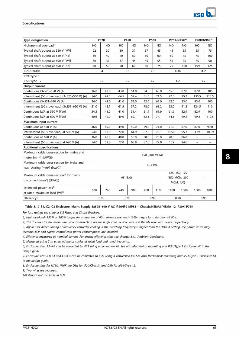
Type designation P37K P45K P55K P75K/N75K8) P90K/N90K8)
High/normal overload1) HO NO HO NO HO NO HO NO HO NO
Typical shaft output at 550 V [kW] 22 30 30 37 37 45 45 55 55 75
Typical shaft output at 550 V [hp] 30 40 40 50 50 60 60 75 75 100
Typical shaft output at 690 V [kW] 30 37 37 45 45 55 55 75 75 90
Typical shaft output at 690 V [hp] 40 50 50 60 60 75 75 100 199 125
IP20/Chassis B4 C3 C3 D3h D3h
IP21/Type 1IP55/Type 12 C2 C2 C2 C2 C2
Output current
Continuous (3x525–550 V) [A] 36.0 43.0 43.0 54.0 54.0 65.0 65.0 87.0 87.0 105
Intermittent (60 s overload) (3x525–550 V) [A] 54.0 47.3 64.5 59.4 81.0 71.5 97.5 95.7 130.5 115.5
Continuous (3x551–690 V) [A] 34.0 41.0 41.0 52.0 52.0 62.0 62.0 83.0 83.0 100
Intermittent (60 s overload) (3x551–690 V) [A] 51.0 45.1 61.5 57.2 78.0 68.2 93.0 91.3 124.5 110
Continuous kVA at 550 V [kVA] 34.3 41.0 41.0 51.4 51.4 61.9 61.9 82.9 82.9 100
Continuous kVA at 690 V [kVA] 40.6 49.0 49.0 62.1 62.1 74.1 74.1 99.2 99.2 119.5
Maximum input current
Continuous at 550 V [A] 36.0 49.0 49.0 59.0 59.0 71.0 71.0 87.0 87.0 99.0
Intermittent (60 s overload) at 550 V [A] 54.0 53.9 72.0 64.9 87.0 78.1 105.0 95.7 129 108.9
Continuous at 690 V [A] 36.0 48.0 48.0 58.0 58.0 70.0 70.0 86.0 – –
Intermittent (60 s overload) at 690 V [A] 54.0 52.8 72.0 63.8 87.0 77.0 105 94.6 – –
Additional specifications
Maximum cable cross-section for mains and
motor [mm2] ([AWG])150 (300 MCM)
Maximum cable cross-section for brake and
load sharing [mm2] ([AWG]) 95 (3/0)
Maximum cable cross-section2) for mains
disconnect [mm2] ([AWG])95 (3/0)
185, 150, 120(350 MCM, 300
MCM, 4/0)–
Estimated power loss3)
at rated maximum load [W]4)600 740 740 900 900 1100 1100 1500 1500 1800
Efficiency5) 0.98 0.98 0.98 0.98 0.98
Table 8.17 B4, C2, C3 Enclosure, Mains Supply 3x525–690 V AC IP20/IP21/IP55 – Chassis/NEMA1/NEMA 12, P30K–P75K
For fuse ratings see chapter 8.8 Fuses and Circuit Breakers.
1) High overload=150% or 160% torque for a duration of 60 s. Normal overload=110% torque for a duration of 60 s.2) The 3 values for the maximum cable cross-section are for single core, flexible wire and flexible wire with sleeve, respectively.3) Applies for dimensioning of frequency converter cooling. If the switching frequency is higher than the default setting, the power losses may
increase. LCP and typical control card power consumptions are included.4) Efficiency measured at nominal current. For energy efficiency class see chapter 8.4.1 Ambient Conditions.5) Measured using 5 m screened motor cables at rated load and rated frequency.
6) Enclosure sizes A2+A3 can be converted to IP21 using a conversion kit. See also Mechanical mounting and IP21/Type 1 Enclosure kit in thedesign guide.7) Enclosure sizes B3+B4 and C3+C4 can be converted to IP21 using a conversion kit. See also Mechanical mounting and IP21/Type 1 Enclosure kit
in the design guide.8) Enclosure sizes for N75K, N90K are D3h for IP20/Chassis, and D5h for IP54/Type 12.9) Two wires are required.
10) Variant not available in IP21.
Specifications
MG21H202 4073.8/02-EN All rights reserved. 63
8 8

8.2 Mains Supply
Mains supply (L1, L2, L3)Supply voltage 200–240 V ±10%Supply voltage 380–480 V ±10%Supply voltage 525–600 V ±10%Supply voltage 525–690 V ±10%
Mains voltage low/mains drop-out:During low mains voltage or a mains drop-out, the frequency converter continues until the intermediate circuit voltage dropsbelow the minimum stop level. Typically this corresponds to 15% below the lowest rated supply voltage of the frequencyconverter. Power-up and full torque cannot be expected at mains voltage <10% below the lowest rated supply voltage of thefrequency converter.
Supply frequency 50/60 Hz +4/-6%
The frequency converter power supply is tested in accordance with IEC61000-4-28, 50 Hz +4/-6%.
Maximum imbalance temporary between mains phases 3.0% of rated supply voltageTrue power factor (λ) ≥0.9 nominal at rated loadDisplacement power factor (cosφ) near unity (>0.98)Switching on input supply L1, L2, L3 (power-ups) ≤7.5 kW maximum 2 times/min.Switching on input supply L1, L2, L3 (power-ups) 11–90 kW maximum 1 time/min.Environment according to EN 60664-1 overvoltage category III/pollution degree 2
The unit is suitable for use on a circuit capable of delivering not more than 100000 RMS symmetrical Amperes,240/480/600/690 V maximum.
8.3 Motor Output and Motor Data
Motor output (U, V, W)Output voltage 0–100% of supply voltageOutput frequency 0–590 Hz1)
Switching on output UnlimitedRamp times 1–3600 s
1) Dependent on power size.
Torque characteristics, normal overloadStarting torque (constant torque) maximum 110% for 1 minute, once in 10 minutes2)
Overload torque (constant torque) maximum 110% for 1 minute, once in 10 minutes2)
Torque characteristics, high overloadStarting torque (constant torque) maximum 150/160% for 1 minute, once in 10 minutes2)
Overload torque (constant torque) maximum 150/160% for 1 minute, once in 10 minutes2)
2) Percentage relates to the nominal torque of the frequency converter, dependent on power size.
Specifications
64 4073.8/02-EN All rights reserved. MG21H202
88

8.4 Ambient Conditions
EnvironmentEnclosure size A IP20/Chassis, IP21/Type 1, IP55/Type 12, IP66/Type 4XEnclosure size B1/B2 IP21/Type 1, IP55/Type 12, IP66/Type 4XEnclosure size B3/B4 IP20/ChassisEnclosure size C1/C2 IP21/Type 1, IP55/Type 12, IP66/Type 4XEnclosure size C3/C4 IP20/ChassisEnclosure kit available ≤ enclosure size A IP21/TYPE 1/IP4X topVibration test enclosure A/B/C 1.0 gMaximum relative humidity 5–95% (IEC 721-3-3; Class 3K3 (non-condensing) during operationAggressive environment (IEC 721-3-3), uncoated class 3C2Aggressive environment (IEC 721-3-3), coated class 3C3Test method according to IEC 60068-2-43 H2S (10 days)Ambient temperature Maximum 50 °C
Derating for high ambient temperature, see section on special conditions in the Design Guide.
Minimum ambient temperature during full-scale operation 0 °CMinimum ambient temperature at reduced performance -10 °CTemperature during storage/transport -25 to +65/70 °CMaximum altitude above sea level without derating 1000 mMaximum altitude above sea level with derating 3000 m
Derating for high altitude, see section on special conditions in the Design Guide.
EMC standards, Emission EN 61800-3EMC standards, Immunity EN 61800-3Energy efficiency class1) IE2
1) Determined according to EN50598-2 at:
• Rated load
• 90% rated frequency
• Switching frequency factory setting
• Switching pattern factory setting
8.5 Cable Specifications
Maximum motor cable length, screened/armoured 150 mMaximum motor cable length, unscreened/unarmoured 300 mMaximum cross section to motor, mains, load sharing and brake1)
Maximum cross section to control terminals, rigid wire 1.5 mm2/16 AWG (2 x 0.75 mm2)Maximum cross section to control terminals, flexible cable 1 mm2/18 AWGMaximum cross section to control terminals, cable with enclosed core 0.5 mm2/20 AWGMinimum cross section to control terminals 0.25 mm2
1) See electrical data tables in chapter 8.1 Electrical Data for more information.
It is mandatory to ground the mains connection properly using T95 (PE) of the frequency converter. The ground connectioncable cross section must be at least 10 mm2 or 2 rated mains wires terminated separately according to EN 50178. See alsochapter 4.3.1 Grounding. Use unscreened cable.
8.6 Control Input/Output and Control Data
Control card, RS485 serial communicationTerminal number 68 (P,TX+, RX+), 69 (N,TX-, RX-)Terminal number 61 common for terminals 68 and 69
The RS485 serial communication circuit is functionally separated from other central circuits and galvanically isolated from thesupply voltage (PELV).
Specifications
MG21H202 4073.8/02-EN All rights reserved. 65
8 8

Analog inputsNumber of analog inputs 2Terminal number 53, 54Modes voltage or currentMode select switches S201 and S202Voltage mode switch S201/S202 = OFF (U)Voltage level 0-10 V (scaleable)Input resistance, Ri approximately 10 kΩMaximum voltage ±20 VCurrent mode switch S201/S202=On (I)Current level 0/4-20 mA (scaleable)Input resistance, Ri approximately 200 ΩMaximum current 30 mAResolution for analog inputs 10 bit (+ sign)Accuracy of analog inputs maximum error 0.5% of full scaleBandwidth 200 Hz
The analog inputs are galvanically isolated from the supply voltage (PELV) and other high-voltage terminals.
Illustration 8.1 PELV Isolation of Analog Inputs
Analog outputNumber of programmable analog outputs 1Terminal number 42Current range at analog output 0/4–20 mAMaximum resistor load to common at analog output 500 ΩAccuracy on analog output maximum error 0.8% of full scaleResolution on analog output 8 bit
The analog output is galvanically isolated from the supply voltage (PELV) and other high-voltage terminals.
Digital inputsProgrammable digital inputs 4 (6)Terminal number 18, 19, 271), 291), 32, 33,Logic PNP or NPNVoltage level 0–24 V DCVoltage level, logic 0 PNP <5 V DCVoltage level, logic 1 PNP >10 V DCVoltage level, logic 0 NPN >19 V DCVoltage level, logic '1' NPN <14 V DCMaximum voltage on input 28 V DCInput resistance, Ri approximately 4 kΩ
All digital inputs are galvanically isolated from the supply voltage (PELV) and other high-voltage terminals.1) Terminals 27 and 29 can also be programmed as output.
Specifications
66 4073.8/02-EN All rights reserved. MG21H202
88

Digital outputProgrammable digital/pulse outputs 2Terminal number 27, 291)
Voltage level at digital/frequency output 0–24 VMaximum output current (sink or source) 40 mAMaximum load at frequency output 1 kΩMaximum capacitive load at frequency output 10 nFMinimum output frequency at frequency output 0 HzMaximum output frequency at frequency output 32 kHzAccuracy of frequency output maximum error 0.1% of full scaleResolution of frequency outputs 12 bit
1) Terminal 27 and 29 can also be programmed as input.
The digital output is galvanically isolated from the supply voltage (PELV) and other high-voltage terminals.
Pulse inputsProgrammable pulse inputs 2Terminal number pulse 29, 33Maximum frequency at terminal 29, 33 110 kHz (push-pull driven)Maximum frequency at terminal 29, 33 5 kHz (open collector)Minimum frequency at terminal 29, 33 4 HzVoltage level see Digital inputsMaximum voltage on input 28 V DCInput resistance, Ri approx. 4 kΩPulse input accuracy (0.1–1 kHz) maximum error 0.1% of full scale
Control card, 24 V DC outputTerminal number 12, 13Maximum load 200 mA
The 24 V DC supply is galvanically isolated from the supply voltage (PELV), but has the same potential as the analog and digitalinputs and outputs.
Relay outputsProgrammable relay outputs 2Relay 01 terminal number 1-3 (break), 1-2 (make)Maximum terminal load (AC-1)1) on 1-3 (NC), 1-2 (NO) (resistive load) 240 V AC, 2 AMaximum terminal load (AC-15)1) (inductive load @ cosφ 0.4) 240 V AC, 0.2 AMaximum terminal load (DC-1)1) on 1-2 (NO), 1-3 (NC) (resistive load) 60 V DC, 1 AMaximum terminal load (DC-13)1) (inductive load) 24 V DC, 0.1 ARelay 02 terminal number 4-6 (break), 4-5 (make)Maximum terminal load (AC-1)1) on 4-5 (NO) (resistive load)2) 3) 400 V AC, 2 AMaximum terminal load (AC-15)1) on 4-5 (NO) (inductive load @ cosφ 0.4) 240 V AC, 0.2 AMaximum terminal load (DC-1)1) on 4-5 (NO) (resistive load) 80 V DC, 2 AMaximum terminal load (DC-13)1) on 4-5 (NO) (inductive load) 24 V DC, 0.1 AMaximum terminal load (AC-1)1) on 4-6 (NC) (resistive load) 240 V AC, 2 AMaximum terminal load (AC-15)1) on 4-6 (NC) (inductive load @ cosφ 0.4) 240 V AC, 0.2 AMaximum terminal load (DC-1)1) on 4-6 (NC) (resistive load) 50 V DC, 2 AMaximum terminal load (DC-13)1) on 4-6 (NC) (inductive load) 24 V DC, 0.1 AMinimum terminal load on 1-3 (NC), 1-2 (NO), 4-6 (NC), 4-5 (NO) 24 V DC, 10 mA, 24 V AC, 20 mAEnvironment according to EN 60664-1 overvoltage category III/pollution degree 2
1) IEC 60947 parts 4 and 5.The relay contacts are galvanically isolated from the rest of the circuit by reinforced isolation (PELV). 2) Overvoltage category II.3) UL applications 300 V AC 2 A.
Specifications
MG21H202 4073.8/02-EN All rights reserved. 67
8 8
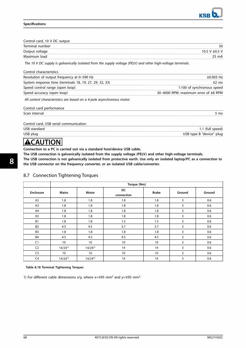
Control card, 10 V DC outputTerminal number 50Output voltage 10.5 V ±0.5 VMaximum load 25 mA
The 10 V DC supply is galvanically isolated from the supply voltage (PELV) and other high-voltage terminals.
Control characteristicsResolution of output frequency at 0–590 Hz ±0.003 HzSystem response time (terminals 18, 19, 27, 29, 32, 33) ≤2 msSpeed control range (open loop) 1:100 of synchronous speedSpeed accuracy (open loop) 30–4000 RPM: maximum error of ±8 RPM
All control characteristics are based on a 4-pole asynchronous motor.
Control card performanceScan interval 5 ms
Control card, USB serial communicationUSB standard 1.1 (full speed)USB plug USB type B “device” plug
CAUTIONConnection to a PC is carried out via a standard host/device USB cable.The USB connection is galvanically isolated from the supply voltage (PELV) and other high-voltage terminals.The USB connection is not galvanically isolated from protective earth. Use only an isolated laptop/PC as a connection tothe USB connector on the frequency converter, or an isolated USB cable/converter.
8.7 Connection Tightening Torques
Torque [Nm]
Enclosure Mains MotorDC
connectionBrake Ground Ground
A2 1.8 1.8 1.8 1.8 3 0.6
A3 1.8 1.8 1.8 1.8 3 0.6
A4 1.8 1.8 1.8 1.8 3 0.6
A5 1.8 1.8 1.8 1.8 3 0.6
B1 1.8 1.8 1.5 1.5 3 0.6
B2 4.5 4.5 3.7 3.7 3 0.6
B3 1.8 1.8 1.8 1.8 3 0.6
B4 4.5 4.5 4.5 4.5 3 0.6
C1 10 10 10 10 3 0.6
C2 14/241) 14/241) 14 14 3 0.6
C3 10 10 10 10 3 0.6
C4 14/241) 14/241) 14 14 3 0.6
Table 8.18 Terminal Tightening Torques
1) For different cable dimensions x/y, where x=≤95 mm2 and y=≥95 mm2.
Specifications
68 4073.8/02-EN All rights reserved. MG21H202
88

8.8 Fuses and Circuit Breakers
Use recommended fuses and/or circuit breakers on the supply side as protection in case of component break-down insidethe frequency converter (first fault).
NOTICEUse of fuses on the supply side is mandatory for IEC 60364 (CE) and NEC 2009 (UL) compliant installations.
Recommendations:
• gG type fuses.
• Moeller type circuit breakers. For other circuit breaker types, ensure that the energy into the frequency converter isequal to or lower than the energy provided by Moeller types.
Use of recommended fuses and circuit breakers ensures that possible damage to the frequency converter is limited todamages inside the unit. For further information, see Application Note Fuses and Circuit Breakers.
The fuses in chapter 8.8.1 CE Compliance to chapter 8.8.2 UL Compliance are suitable for use on a circuit capable of delivering100000 Arms (symmetrical), depending on the frequency converter voltage rating. With the proper fusing, the frequencyconverter short-circuit current rating (SCCR) is 100000 Arms.
8.8.1 CE Compliance
200–240 V, Enclosure sizes A, B, and C
Enclosure Power [kW] Recommendedfuse size
Recommendedmaximum fuse
Recommended circuitbreakerMoeller
Maximum trip level[A]
A2 0.25–2.2 gG-10 (0.25–1.5)
gG-16 (2.2)
gG-25 PKZM0-25 25
A3 3.0–3.7 gG-16 (3)gG-20 (3.7)
gG-32 PKZM0-25 25
A4 0.25–2.2 gG-10 (0.25–1.5)gG-16 (2.2)
gG-32 PKZM0-25 25
A5 0.25–3.7 gG-10 (0.25–1.5)gG-16 (2.2–3)
gG-20 (3.7)
gG-32 PKZM0-25 25
B1 5.5–11 gG-25 (5.5)
gG-32 (7.5)
gG-80 PKZM4-63 63
B2 15 gG-50 gG-100 NZMB1-A100 100
B3 5.5–11 gG-25 gG-63 PKZM4-50 50
B4 15–18 gG-32 (7.5)gG-50 (11)gG-63 (15)
gG-125 NZMB1-A100 100
C1 18.5–30 gG-63 (15)gG-80 (18.5)gG-100 (22)
gG-160 (15–18.5)aR-160 (22)
NZMB2-A200 160
C2 37–45 aR-160 (30)aR-200 (37)
aR-200 (30)aR-250 (37)
NZMB2-A250 250
C3 22–30 gG-80 (18.5)
aR-125 (22)
gG-150 (18.5)
aR-160 (22)
NZMB2-A200 150
C4 37–45 aR-160 (30)aR-200 (37)
aR-200 (30)aR-250 (37)
NZMB2-A250 250
Table 8.19 200–240 V, Enclosure Sizes A, B, and C
Specifications
MG21H202 4073.8/02-EN All rights reserved. 69
8 8
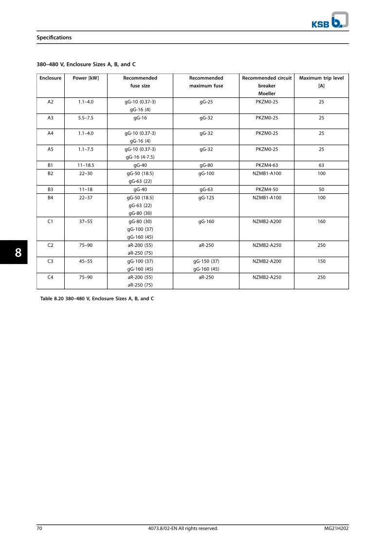
380–480 V, Enclosure Sizes A, B, and C
Enclosure Power [kW] Recommendedfuse size
Recommendedmaximum fuse
Recommended circuitbreakerMoeller
Maximum trip level[A]
A2 1.1–4.0 gG-10 (0.37-3)gG-16 (4)
gG-25 PKZM0-25 25
A3 5.5–7.5 gG-16 gG-32 PKZM0-25 25
A4 1.1–4.0 gG-10 (0.37-3)gG-16 (4)
gG-32 PKZM0-25 25
A5 1.1–7.5 gG-10 (0.37-3)gG-16 (4-7.5)
gG-32 PKZM0-25 25
B1 11–18.5 gG-40 gG-80 PKZM4-63 63
B2 22–30 gG-50 (18.5)gG-63 (22)
gG-100 NZMB1-A100 100
B3 11–18 gG-40 gG-63 PKZM4-50 50
B4 22–37 gG-50 (18.5)gG-63 (22)gG-80 (30)
gG-125 NZMB1-A100 100
C1 37–55 gG-80 (30)gG-100 (37)gG-160 (45)
gG-160 NZMB2-A200 160
C2 75–90 aR-200 (55)
aR-250 (75)
aR-250 NZMB2-A250 250
C3 45–55 gG-100 (37)
gG-160 (45)
gG-150 (37)
gG-160 (45)
NZMB2-A200 150
C4 75–90 aR-200 (55)aR-250 (75)
aR-250 NZMB2-A250 250
Table 8.20 380–480 V, Enclosure Sizes A, B, and C
Specifications
70 4073.8/02-EN All rights reserved. MG21H202
88

525–600 V, Enclosure Sizes A, B, and C
Enclosure Power [kW] Recommendedfuse size
Recommendedmaximum fuse
Recommended circuitbreakerMoeller
Maximum trip level[A]
A2 1.1–4.0 gG-10 gG-25 PKZM0-25 25
A3 5.5–7.5 gG-10 (5.5)gG-16 (7.5)
gG-32 PKZM0-25 25
A5 1.1–7.5 gG-10 (0.75-5.5)gG-16 (7.5)
gG-32 PKZM0-25 25
B1 11–18 gG-25 (11)
gG-32 (15)gG-40 (18.5)
gG-80 PKZM4-63 63
B2 22–30 gG-50 (22)gG-63 (30)
gG-100 NZMB1-A100 100
B3 11–18.5 gG-25 (11)gG-32 (15)
gG-63 PKZM4-50 50
B4 22–37 gG-40 (18.5)gG-50 (22)gG-63 (30)
gG-125 NZMB1-A100 100
C1 37–55 gG-63 (37)gG-100 (45)aR-160 (55)
gG-160 (37-45)aR-250 (55)
NZMB2-A200 160
C2 75–90 aR-200 (75) aR-250 NZMB2-A250 250
C3 45–55 gG-63 (37)
gG-100 (45)
gG-150 NZMB2-A200 150
C4 75–90 aR-160 (55)aR-200 (75)
aR-250 NZMB2-A250 250
Table 8.21 525–600 V, Enclosure Sizes A, B, and C
525-690 V, Enclosure Sizes A, B, and C
Enclosure Power [kW] Recommended fuse size Recommendedmaximum fuse
Recommended circuitbreaker
KSB
Maximum triplevel [A]
A3
1.1 gG-6 gG-25 CTI25M 10-16 16
1.5 gG-6 gG-25 CTI25M 10-16 16
2.2 gG-6 gG-25 CTI25M 10-16 16
3 gG-10 gG-25 CTI25M 10-16 16
4 gG-10 gG-25 CTI25M 10-16 16
5.5 gG-16 gG-25 CTI25M 10-16 16
7.5 gG-16 gG-25 CTI25M 10-16 16
B2
11 gG-25 gG-63
15 gG-25 gG-63
18 gG-32
22 gG-32
C2
30 gG-40
37 gG-63 gG-80
45 gG-63 gG-100
55 gG-80 gG-125
75 gG-100 gG-160
C337 gG-100 gG-125
45 gG-125 gG-160
Table 8.22 525–690 V, Enclosure Sizes A, B, and C
Specifications
MG21H202 4073.8/02-EN All rights reserved. 71
8 8
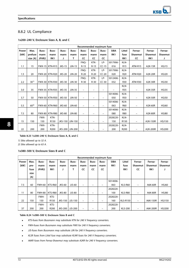
8.8.2 UL Compliance
1x200–240 V, Enclosure Sizes A, B, and C
Recommended maximum fuse
Power[kW]
Max.prefusesize [A]
Buss-mannJFHR2
Buss-mannRK1
Buss-mann
J
Buss-mann
T
Buss-mann
CC
Buss-mann
CC
Buss-mann
CC
SIBARK1
LittelfuseRK1
Ferraz-Shawmut
CC
Ferraz-Shawmut
RK1
Ferraz-Shawmut
J
1.1 15 FWX-15 KTN-R15 JKS-15 JJN-15FNQ-R-15
KTK-R-15
LP-CC-15
5017906-016
KLN-R15 ATM-R15 A2K-15R HSJ15
1.5 20 FWX-20 KTN-R20 JKS-20 JJN-20
FNQ-
R-20
KTK-
R-20
LP-
CC-20
5017906-
020
KLN-
R20 ATM-R20 A2K-20R HSJ20
2.2 301) FWX-30 KTN-R30 JKS-30 JJN-30
FNQ-
R-30
KTK-
R-30
LP-
CC-30
5012406-
032
KLN-
R30 ATM-R30 A2K-30R HSJ30
3.0 35 FWX-35 KTN-R35 JKS-35 JJN-35 – – – –KLN-R35 – A2K-35R HSJ35
3.7 50 FWX-50 KTN-R50 JKS-50 JJN-50 – – –5014006-
050KLN-R50 – A2K-50R HSJ50
5.5 602) FWX-60 KTN-R60 JKS-60 JJN-60 – – –5014006-
063KLN-R60 – A2K-60R HSJ60
7.5 80 FWX-80 KTN-R80 JKS-80 JJN-80 – – –
5014006-
080
KLN-
R80 – A2K-80R HSJ80
15 150
FWX-
150
KTN-
R150 JKS-150 JJN-150 – – –
2028220-
150
KLN-
R150 – A2K-150R HSJ150
22 200FWX-200
KTN-R200 JKS-200 JJN-200 – – –
2028220-200
KLN-R200 – A2K-200R HSJ200
Table 8.23 1x200–240 V, Enclosure Sizes A, B, and C
1) Siba allowed up to 32 A.2) Siba allowed up to 63 A.
1x380–500 V, Enclosure Sizes B and C
Recommended maximum fuse
Power[kW]
Max.pre-fusesize[A]
Buss-mannJFHR2
Buss-mannRK1
Buss-mann
J
Buss-mann
T
Buss-mann
CC
Buss-mann
CC
Buss-mann
CC
SIBARK1
LittelfuseRK1
Ferraz-Shawmut
CC
Ferraz-Shawmut
RK1
Ferraz-Shawmut
J
7.5 60 FWH-60 KTS-R60 JKS-60 JJS-60 – – –5014006-
063 KLS-R60 – A6K-60R HSJ60
11 80 FWH-80 KTS-R80 JKS-80 JJS-80 – – –2028220-
100 KLS-R80 – A6K-80R HSJ80
22 150
FWH-
150
KTS-
R150 JKS-150 JJS-150 – – –
2028220-
160 KLS-R150 – A6K-150R HSJ150
37 200
FWH-
200
KTS-
R200 JKS-200 JJS-200 – – –
2028220-
200 KLS-200 – A6K-200R HSJ200
Table 8.24 1x380–500 V, Enclosure Sizes B and C
• KTS-fuses from Bussmann may substitute KTN for 240 V frequency converters.
• FWH-fuses from Bussmann may substitute FWX for 240 V frequency converters.
• JJS-fuses from Bussmann may substitute JJN for 240 V frequency converters.
• KLSR fuses from Littel fuse may substitute KLNR fuses for 240 V frequency converters.
• A6KR fuses from Ferraz-Shawmut may substitute A2KR for 240 V frequency converters.
Specifications
72 4073.8/02-EN All rights reserved. MG21H202
88

3x200–240 V, Enclosure Sizes A, B, and C
Recommended maximum fuse
Power [kW] Bussmann
Type RK1 1)
BussmannType J
BussmannType T
BussmannType CC
Bussmann BussmannType CC
0.25–0.37 KTN-R-05 JKS-05 JJN-05 FNQ-R-5 KTK-R-5 LP-CC-5
0.55–1.1 KTN-R-10 JKS-10 JJN-10 FNQ-R-10 KTK-R-10 LP-CC-10
1.5 KTN-R-15 JKS-15 JJN-15 FNQ-R-15 KTK-R-15 LP-CC-15
2.2 KTN-R-20 JKS-20 JJN-20 FNQ-R-20 KTK-R-20 LP-CC-20
3.0 KTN-R-25 JKS-25 JJN-25 FNQ-R-25 KTK-R-25 LP-CC-25
3.7 KTN-R-30 JKS-30 JJN-30 FNQ-R-30 KTK-R-30 LP-CC-30
5.5–7.5 KTN-R-50 JKS-50 JJN-50 – – –
11 KTN-R-60 JKS-60 JJN-60 – – –
15 KTN-R-80 JKS-80 JJN-80 – – –
18.5–22 KTN-R-125 JKS-125 JJN-125 – – –
30 KTN-R-150 JKS-150 JJN-150 – – –
37 KTN-R-200 JKS-200 JJN-200 – – –
45 KTN-R-250 JKS-250 JJN-250 – – –
Table 8.25 3x200–240 V, Enclosure Sizes A, B, and C
Recommended maximum fuse
Power[kW]
SIBAType RK1
Littel fuseType RK1
Ferraz-ShawmutType CC
Ferraz-Shawmut
Type RK12)
Bussmann
Type JFHR23)
Littel fuseJFHR2
Ferraz-Shawmut
JFHR24)
Ferraz-Shawmut
J
0.25–0.37 5017906-005 KLN-R-05 ATM-R-05 A2K-05-R FWX-5 – – HSJ-6
0.55–1.1 5017906-010 KLN-R-10 ATM-R-10 A2K-10-R FWX-10 – – HSJ-10
1.5 5017906-016 KLN-R-15 ATM-R-15 A2K-15-R FWX-15 – – HSJ-15
2.2 5017906-020 KLN-R-20 ATM-R-20 A2K-20-R FWX-20 – – HSJ-20
3.0 5017906-025 KLN-R-25 ATM-R-25 A2K-25-R FWX-25 – – HSJ-25
3.7 5012406-032 KLN-R-30 ATM-R-30 A2K-30-R FWX-30 – – HSJ-30
5.5–7.5 5014006-050 KLN-R-50 – A2K-50-R FWX-50 – – HSJ-50
11 5014006-063 KLN-R-60 – A2K-60-R FWX-60 – – HSJ-60
15 5014006-080 KLN-R-80 – A2K-80-R FWX-80 – – HSJ-80
18.5–22 2028220-125 KLN-R-125 – A2K-125-R FWX-125 – – HSJ-125
30 2028220-150 KLN-R-150 – A2K-150-R FWX-150 L25S-150 A25X-150 HSJ-150
37 2028220-200 KLN-R-200 – A2K-200-R FWX-200 L25S-200 A25X-200 HSJ-200
45 2028220-250 KLN-R-250 – A2K-250-R FWX-250 L25S-250 A25X-250 HSJ-250
Table 8.26 3x200–240 V, Enclosure Sizes A, B, and C
1) KTS-fuses from Bussmann may substitute KTN for 240 V frequency converters.2) A6KR fuses from Ferraz-Shawmut may substitute A2KR for 240 V frequency converters.3) FWH-fuses from Bussmann may substitute FWX for 240 V frequency converters.4) A50X fuses from Ferraz-Shawmut may substitute A25X for 240 V frequency converters.
Specifications
MG21H202 4073.8/02-EN All rights reserved. 73
8 8
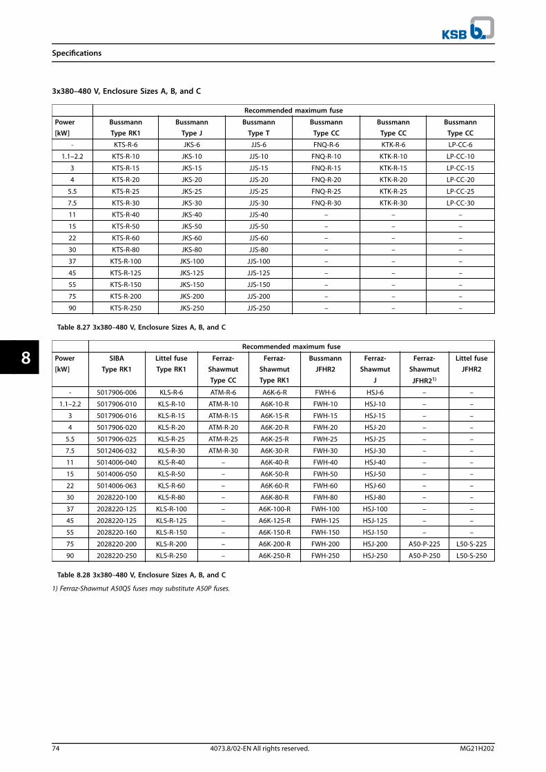
3x380–480 V, Enclosure Sizes A, B, and C
Recommended maximum fuse
Power[kW]
BussmannType RK1
BussmannType J
BussmannType T
BussmannType CC
BussmannType CC
BussmannType CC
- KTS-R-6 JKS-6 JJS-6 FNQ-R-6 KTK-R-6 LP-CC-6
1.1–2.2 KTS-R-10 JKS-10 JJS-10 FNQ-R-10 KTK-R-10 LP-CC-10
3 KTS-R-15 JKS-15 JJS-15 FNQ-R-15 KTK-R-15 LP-CC-15
4 KTS-R-20 JKS-20 JJS-20 FNQ-R-20 KTK-R-20 LP-CC-20
5.5 KTS-R-25 JKS-25 JJS-25 FNQ-R-25 KTK-R-25 LP-CC-25
7.5 KTS-R-30 JKS-30 JJS-30 FNQ-R-30 KTK-R-30 LP-CC-30
11 KTS-R-40 JKS-40 JJS-40 – – –
15 KTS-R-50 JKS-50 JJS-50 – – –
22 KTS-R-60 JKS-60 JJS-60 – – –
30 KTS-R-80 JKS-80 JJS-80 – – –
37 KTS-R-100 JKS-100 JJS-100 – – –
45 KTS-R-125 JKS-125 JJS-125 – – –
55 KTS-R-150 JKS-150 JJS-150 – – –
75 KTS-R-200 JKS-200 JJS-200 – – –
90 KTS-R-250 JKS-250 JJS-250 – – –
Table 8.27 3x380–480 V, Enclosure Sizes A, B, and C
Recommended maximum fuse
Power[kW]
SIBAType RK1
Littel fuseType RK1
Ferraz-ShawmutType CC
Ferraz-ShawmutType RK1
BussmannJFHR2
Ferraz-Shawmut
J
Ferraz-Shawmut
JFHR21)
Littel fuseJFHR2
- 5017906-006 KLS-R-6 ATM-R-6 A6K-6-R FWH-6 HSJ-6 – –
1.1–2.2 5017906-010 KLS-R-10 ATM-R-10 A6K-10-R FWH-10 HSJ-10 – –
3 5017906-016 KLS-R-15 ATM-R-15 A6K-15-R FWH-15 HSJ-15 – –
4 5017906-020 KLS-R-20 ATM-R-20 A6K-20-R FWH-20 HSJ-20 – –
5.5 5017906-025 KLS-R-25 ATM-R-25 A6K-25-R FWH-25 HSJ-25 – –
7.5 5012406-032 KLS-R-30 ATM-R-30 A6K-30-R FWH-30 HSJ-30 – –
11 5014006-040 KLS-R-40 – A6K-40-R FWH-40 HSJ-40 – –
15 5014006-050 KLS-R-50 – A6K-50-R FWH-50 HSJ-50 – –
22 5014006-063 KLS-R-60 – A6K-60-R FWH-60 HSJ-60 – –
30 2028220-100 KLS-R-80 – A6K-80-R FWH-80 HSJ-80 – –
37 2028220-125 KLS-R-100 – A6K-100-R FWH-100 HSJ-100 – –
45 2028220-125 KLS-R-125 – A6K-125-R FWH-125 HSJ-125 – –
55 2028220-160 KLS-R-150 – A6K-150-R FWH-150 HSJ-150 – –
75 2028220-200 KLS-R-200 – A6K-200-R FWH-200 HSJ-200 A50-P-225 L50-S-225
90 2028220-250 KLS-R-250 – A6K-250-R FWH-250 HSJ-250 A50-P-250 L50-S-250
Table 8.28 3x380–480 V, Enclosure Sizes A, B, and C
1) Ferraz-Shawmut A50QS fuses may substitute A50P fuses.
Specifications
74 4073.8/02-EN All rights reserved. MG21H202
88
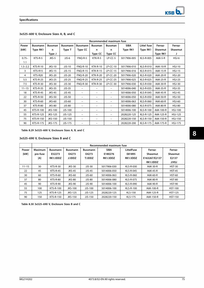
3x525–600 V, Enclosure Sizes A, B, and C
Recommended maximum fuse
Power[kW]
BussmannType RK1
Bussmann
Type J
BussmannType T
BussmannType CC
Bussmann
Type CC
Bussmann
Type CC
SIBAType RK1
Littel fuseType RK1
Ferraz-ShawmutType RK1
Ferraz-Shawmut
J
0.75–
1.1
KTS-R-5 JKS-5 JJS-6 FNQ-R-5 KTK-R-5 LP-CC-5 5017906-005 KLS-R-005 A6K-5-R HSJ-6
1.5–2.2 KTS-R-10 JKS-10 JJS-10 FNQ-R-10 KTK-R-10 LP-CC-10 5017906-010 KLS-R-010 A6K-10-R HSJ-10
3 KTS-R15 JKS-15 JJS-15 FNQ-R-15 KTK-R-15 LP-CC-15 5017906-016 KLS-R-015 A6K-15-R HSJ-15
4 KTS-R20 JKS-20 JJS-20 FNQ-R-20 KTK-R-20 LP-CC-20 5017906-020 KLS-R-020 A6K-20-R HSJ-20
5.5 KTS-R-25 JKS-25 JJS-25 FNQ-R-25 KTK-R-25 LP-CC-25 5017906-025 KLS-R-025 A6K-25-R HSJ-25
7.5 KTS-R-30 JKS-30 JJS-30 FNQ-R-30 KTK-R-30 LP-CC-30 5017906-030 KLS-R-030 A6K-30-R HSJ-30
11–15 KTS-R-35 JKS-35 JJS-35 – – – 5014006-040 KLS-R-035 A6K-35-R HSJ-35
18 KTS-R-45 JKS-45 JJS-45 – – – 5014006-050 KLS-R-045 A6K-45-R HSJ-45
22 KTS-R-50 JKS-50 JJS-50 – – – 5014006-050 KLS-R-050 A6K-50-R HSJ-50
30 KTS-R-60 JKS-60 JJS-60 – – – 5014006-063 KLS-R-060 A6K-60-R HSJ-60
37 KTS-R-80 JKS-80 JJS-80 – – – 5014006-080 KLS-R-075 A6K-80-R HSJ-80
45 KTS-R-100 JKS-100 JJS-100 – – – 5014006-100 KLS-R-100 A6K-100-R HSJ-100
55 KTS-R-125 JKS-125 JJS-125 – – – 2028220-125 KLS-R-125 A6K-125-R HSJ-125
75 KTS-R-150 JKS-150 JJS-150 – – – 2028220-150 KLS-R-150 A6K-150-R HSJ-150
90 KTS-R-175 JKS-175 JJS-175 – – – 2028220-200 KLS-R-175 A6K-175-R HSJ-175
Table 8.29 3x525–600 V, Enclosure Sizes A, B, and C
3x525–690 V, Enclosure Sizes B and C
Recommended maximum fuse
Power[kW]
Maximumpre-fuse
[A]
BussmannE52273
RK1/JDDZ
BussmannE4273J/JDDZ
BussmannE4273
T/JDDZ
SIBAE180276
RK1/JDDZ
LittelFuseE81895
RK1/JDDZ
Ferraz-Shawmut
E163267/E2137RK1/JDDZ
Ferraz-Shawmut
E2137J/HSJ
11–15 30 KTS-R-30 JKS-30 JJS-30 5017906-030 KLS-R-030 A6K-30-R HST-30
22 45 KTS-R-45 JKS-45 JJS-45 5014006-050 KLS-R-045 A6K-45-R HST-45
30 60 KTS-R-60 JKS-60 JJS-60 5014006-063 KLS-R-060 A6K-60-R HST-60
37 80 KTS-R-80 JKS-80 JJS-80 5014006-080 KLS-R-075 A6K-80-R HST-80
45 90 KTS-R-90 JKS-90 JJS-90 5014006-100 KLS-R-090 A6K-90-R HST-90
55 100 KTS-R-100 JKS-100 JJS-100 5014006-100 KLS-R-100 A6K-100-R HST-100
75 125 KTS-R-125 JKS-125 JJS-125 2028220-125 KLS-150 A6K-125-R HST-125
90 150 KTS-R-150 JKS-150 JJS-150 2028220-150 KLS-175 A6K-150-R HST-150
Table 8.30 3x525–690 V, Enclosure Sizes B and C
Specifications
MG21H202 4073.8/02-EN All rights reserved. 75
8 8

8.9 Power Ratings, Weight, and Dimensions
Enclosure size [kW] A2 A3 A4 A5
3x525-690 V T7 – – – –
3x525-600 V T6 – 0.75–7.5 – 0.75–7.5
3x380-480 V T4 0.37–4.0 5.5–7.5 0.37–4.0 0.37–7.5
1x380-480 V S4 – – 1.1–4.0 –
3x200-240 V T2 0.25–3.0 3.7 0.25–2.2 0.25–3.7
1x200-240 V S2 – 1.1 1.1–2.2 1.1
IPNEMA
20Chassis
21Type 1
20Chassis
21Type 1
55/66Type 12/4X
55/66Type 12/4X
Height [mm]
Height of back plate A1) 268 375 268 375 390 420
Height with de-coupling plate for fieldbuscables
A 374 – 374 – – –
Distance between mounting holes a 257 350 257 350 401 402
Width [mm]
Width of back plate B 90 90 130 130 200 242
Width of back plate with 1 C option B 130 130 170 170 – 242
Width of back plate with 2 C options B 90 90 130 130 – 242
Distance between mounting holes b 70 70 110 110 171 215
Depth2) [mm]
Without option A/B C 205 205 205 205 175 200
With option A/B C 220 220 220 220 175 200
Screw holes [mm]
c 8.0 8.0 8.0 8.0 8.25 8.2
d ø11 ø11 ø11 ø11 ø12 ø12
e ø5.5 ø5.5 ø5.5 ø5.5 ø6.5 ø6.5
f 9 9 9 9 6 9
Maximum weight [kg] 4.9 5.3 6.6 7.0 9.7 14
1) See Illustration 3.4 and Illustration 3.5 for top and bottom mounting holes.
2) Depth of enclosure will vary with different options installed.
Table 8.31 Power Ratings, Weight, and Dimensions, Enclosure Sizes A2-A5
Specifications
76 4073.8/02-EN All rights reserved. MG21H202
88

Enclosure size [kW] B1 B2 B3 B4 C1 C2 C3 C4
3x525-690 V T7 – 11–30 – – – 37–90 – –
3x525-600 V T6 11–18.5 22–30 11–18.5 22–37 37–55 75–90 45–55 75–90
3x380-480 V T4 11–18.5 22–30 11–18.5 22–37 37–55 75–90 45–55 75–90
1x380-480 V S4 7.5 11 – – 18 37 – –
3x200-240 V T2 5.5–11 15 5.5–11 15–18.5 18.5–30 37–45 22–30 37–45
1x200-240 V S2 1.5–3.7 7.5 – – 15 22 – –
IPNEMA
21/55/66Type 1/12/4X
21/55/66
Type1/12/4X
20Chassis
20Chassis
21/55/66
Type1/12/4X
21/55/66
Type1/12/4X
20Chassis
20Chassis
Height [mm]
Height of back plate A1) 480 650 399 520 680 770 550 660
Height with de-coupling plate for
fieldbus cablesA – – 419 595 – – 630 800
Distance between mountingholes
a 454 624 380 495 648 739 521 631
Width [mm]
Width of back plate B 242 242 165 231 308 370 308 370
Width of back plate with 1 Coption
B 242 242 205 231 308 370 308 370
Width of back plate with 2 C
optionsB 242 242 165 231 308 370 308 370
Distance between mountingholes
b 210 210 140 200 272 334 270 330
Depth2) [mm]
Without option A/B C 260 260 248 242 310 335 333 333
With option A/B C 260 260 262 242 310 335 333 333
Screw holes [mm]
c 12 12 8 – 12 12 – –
d ø19 ø19 12 – ø19 ø19 – –
e ø9 ø9 6.8 8.5 ø9.0 ø9.0 8.5 8.5
f 9 9 7.9 15 9.8 9.8 17 17
Maximum weight [kg] 23 27 12 23.5 45 65 35 50
1) See Illustration 3.4 and Illustration 3.5 for top and bottom mounting holes.2) Depth of enclosure will vary with different options installed.
Table 8.32 Power Ratings, Weight, and Dimensions, Enclosure Sizes B1-B4, C1-C4
Specifications
MG21H202 4073.8/02-EN All rights reserved. 77
8 8

9 Appendix
9.1 Symbols, Abbreviations, and Conventions
°C Degrees celsius
AC Alternating current
AEO Automatic energy optimization
AWG American wire gauge
AMA Automatic motor adaptation
DC Direct current
EMC Electro magnetic compatibility
ETR Electronic thermal relay
fM,N Nominal motor frequency
FC Frequency converter
IINV Rated inverter output current
ILIM Current limit
IM,N Nominal motor current
IVLT,MAX Maximum output current
IVLT,N Rated output current supplied by the frequency converter
IP Ingress protection
LCP Local control panel
MCT Motion control tool
ns Synchronous motor speed
PM,N Nominal motor power
PELV Protective extra low voltage
PCB Printed circuit board
PM Motor Permanent magnet motor
PWM Pulse width modulation
RPM Revolutions per minute
Regen Regenerative terminals
TLIM Torque limit
UM,N Nominal motor voltage
Table 9.1 Symbols and Abbreviations
ConventionsNumbered lists indicate procedures.Bullet lists indicate other information.Italicised text indicates:
• Cross reference.
• Link.
• Parameter name.
All dimensions are in [mm].
9.2 Parameter Menu Structure
Appendix
78 4073.8/02-EN All rights reserved. MG21H202
99

0-**
Ope
ratio
n /
Dis
play
0-0*
Basi
c Se
ttin
gs0-
01La
ngua
ge0-
02M
otor
Spe
ed U
nit
0-03
Regi
onal
Set
tings
0-04
Ope
ratin
g S
tate
at
Pow
er-u
p0-
05Lo
cal M
ode
Uni
t0-
1*Se
t-up
Ope
ratio
ns0-
10Ac
tive
Set-
up0-
11Pr
ogra
mm
ing
Set
-up
0-12
This
Set
-up
Lin
ked
to
0-13
Read
out:
Link
ed S
et-u
ps0-
14Re
adou
t: Pr
og. S
et-u
ps /
Cha
nnel
0-2*
LCP
Dis
play
0-20
Dis
play
Lin
e 1.
1 Sm
all
0-21
Dis
play
Lin
e 1.
2 Sm
all
0-22
Dis
play
Lin
e 1.
3 Sm
all
0-23
Dis
play
Lin
e 2
Larg
e0-
24D
ispl
ay L
ine
3 La
rge
0-25
My
Pers
onal
Men
u0-
3*LC
P C
usto
m R
eado
ut0-
30Cu
stom
Rea
dout
Uni
t0-
31Cu
stom
Rea
dout
Min
Val
ue0-
32Cu
stom
Rea
dout
Max
Val
ue0-
37D
ispl
ay T
ext
10-
38D
ispl
ay T
ext
20-
39D
ispl
ay T
ext
30-
4*LC
P K
eypa
d0-
40[H
and
on]
Key
on
LCP
0-41
[Off]
Key
on
LCP
0-42
[Aut
o o
n] K
ey o
n L
CP0-
43[R
eset
] Ke
y on
LCP
0-44
[Off/
Rese
t] K
ey o
n L
CP0-
45[D
rive
Bypa
ss]
Key
on L
CP0-
5*Co
py/S
ave
0-50
LCP
Copy
0-51
Set-
up C
opy
0-6*
Pass
wor
d0-
60M
ain
Men
u P
assw
ord
0-61
Acce
ss t
o M
ain
Men
u w
/o P
assw
ord
0-65
Pers
onal
Men
u P
assw
ord
0-66
Acce
ss t
o P
erso
nal M
enu
w/o
Pas
swor
d0-
67Bu
s Pa
ssw
ord
Acc
ess
0-7*
Cloc
k Se
ttin
gs0-
70D
ate
and
Tim
e0-
71D
ate
Form
at0-
72Ti
me
Form
at0-
74D
ST/S
umm
ertim
e0-
76D
ST/S
umm
ertim
e St
art
0-77
DST
/Sum
mer
time
End
0-79
Cloc
k Fa
ult
0-81
Wor
king
Day
s0-
82Ad
ditio
nal W
orki
ng D
ays
0-83
Addi
tiona
l Non
-Wor
king
Day
s0-
89D
ate
and
Tim
e Re
adou
t1-
**Lo
ad a
nd M
otor
1-0*
Gen
eral
Set
tings
1-00
Confi
gura
tion
Mod
e1-
01M
otor
Con
trol
Prin
cipl
e
1-03
Torq
ue C
hara
cter
istic
s1-
06Cl
ockw
ise
Dire
ctio
n1-
1*M
otor
Sel
ecti
on1-
10M
otor
Con
stru
ctio
n1-
1*VV
C+ P
M1-
14D
ampi
ng G
ain
1-15
Low
Spe
ed F
ilter
Tim
e Co
nst.
1-16
Hig
h S
peed
Filt
er T
ime
Cons
t.1-
17Vo
ltage
filte
r tim
e co
nst.
1-2*
Mot
or D
ata
1-20
Mot
or P
ower
[kW
]1-
21M
otor
Pow
er [H
P]1-
22M
otor
Vol
tage
1-23
Mot
or F
requ
ency
1-24
Mot
or C
urre
nt1-
25M
otor
Nom
inal
Spe
ed1-
26M
otor
Con
t. Ra
ted
Tor
que
1-28
Mot
or R
otat
ion
Che
ck1-
29Au
tom
atic
Mot
or A
dapt
atio
n (A
MA
)1-
3*A
dv. M
otor
Dat
a1-
30St
ator
Res
ista
nce
(Rs)
1-31
Roto
r Re
sist
ance
(Rr)
1-33
Stat
or L
eaka
ge R
eact
ance
(X1)
1-34
Roto
r Le
akag
e Re
acta
nce
(X2)
1-35
Mai
n R
eact
ance
(Xh)
1-36
Iron
Los
s Re
sist
ance
(Rfe
)1-
37d-
axis
Indu
ctan
ce (L
d)1-
38M
ax. q
-axi
s In
duct
ance
Lq
1-39
Mot
or P
oles
1-40
Back
EM
F at
100
0 RP
M1-
44M
in. d
-axi
s In
duct
ance
Ld
1-45
Min
. q-a
xis
Indu
ctan
ce L
d1-
46Po
sitio
n D
etec
tion
Gai
n1-
48Sa
tura
tion
poi
nt o
f Ld
in %
of
IN1-
5*Lo
ad In
dep.
Set
ting
1-50
Mot
or M
agne
tisat
ion
at
Zero
Spe
ed1-
51M
in S
peed
Nor
mal
Mag
netis
ing
[RPM
]1-
52M
in S
peed
Nor
mal
Mag
netis
ing
[Hz]
1-55
V/f
Char
acte
ristic
- V
1-56
V/f
Char
acte
ristic
- f
1-58
Flys
tart
Tes
t Pu
lses
Cur
rent
1-59
Flys
tart
Tes
t Pu
lses
Fre
quen
cy1-
6*Lo
ad D
epen
. Set
ting
1-60
Low
Spe
ed L
oad
Com
pens
atio
n1-
61H
igh
Spe
ed L
oad
Com
pens
atio
n1-
62Sl
ip C
ompe
nsat
ion
1-63
Slip
Com
pens
atio
n T
ime
Cons
tant
1-64
Reso
nanc
e D
ampe
ning
1-65
Reso
nanc
e D
ampe
ning
Tim
e Co
nsta
nt1-
66M
in. C
urre
nt a
t Lo
w S
peed
1-7*
Star
t A
djus
tmen
ts1-
70PM
Sta
rt M
ode
1-71
Star
t D
elay
1-72
Star
t Fu
nctio
n1-
73Fl
ying
Sta
rt1-
74St
art
Spee
d [R
PM]
1-75
Star
t Sp
eed
[Hz]
1-76
Star
t Cu
rren
t1-
8*St
op A
djus
tmen
ts
1-80
Func
tion
at
Stop
1-81
Min
Spe
ed fo
r Fu
nctio
n a
t St
op [R
PM]
1-82
Min
Spe
ed fo
r Fu
nctio
n a
t St
op [H
z]1-
86Tr
ip S
peed
Low
[RPM
]1-
87Tr
ip S
peed
Low
[Hz]
1-9*
Mot
or T
empe
ratu
re1-
90M
otor
The
rmal
Pro
tect
ion
1-91
Mot
or E
xter
nal F
an1-
93Th
erm
isto
r So
urce
2-**
Brak
es2-
0*D
C-Br
ake
2-00
DC
Hol
d/Pr
ehea
t Cu
rren
t2-
01D
C B
rake
Cur
rent
2-02
DC
Bra
king
Tim
e2-
03D
C B
rake
Cut
In S
peed
[RPM
]2-
04D
C B
rake
Cut
In S
peed
[Hz]
2-06
Park
ing
Cur
rent
2-07
Park
ing
Tim
e2-
1*Br
ake
Ener
gy F
unct
.2-
10Br
ake
Func
tion
2-11
Brak
e Re
sist
or (o
hm)
2-12
Brak
e Po
wer
Lim
it (k
W)
2-13
Brak
e Po
wer
Mon
itorin
g2-
15Br
ake
Chec
k2-
16AC
bra
ke M
ax. C
urre
nt2-
17O
ver-
volta
ge C
ontr
ol2-
19O
ver-
volta
ge G
ain
3-**
Refe
renc
e /
Ram
ps3-
0*Re
fere
nce
Lim
its
3-02
Min
imum
Ref
eren
ce3-
03M
axim
um R
efer
ence
3-04
Refe
renc
e Fu
nctio
n3-
1*Re
fere
nces
3-10
Pres
et R
efer
ence
3-11
Jog
Spe
ed [H
z]3-
13Re
fere
nce
Site
3-14
Pres
et R
elat
ive
Refe
renc
e3-
15Re
fere
nce
1 So
urce
3-16
Refe
renc
e 2
Sour
ce3-
17Re
fere
nce
3 So
urce
3-19
Jog
Spe
ed [R
PM]
3-4*
Ram
p 1
3-41
Ram
p 1
Ram
p U
p T
ime
3-42
Ram
p 1
Ram
p D
own
Tim
e3-
5*Ra
mp
23-
51Ra
mp
2 R
amp
Up
Tim
e3-
52Ra
mp
2 R
amp
Dow
n T
ime
3-8*
Oth
er R
amps
3-80
Jog
Ram
p T
ime
3-81
Qui
ck S
top
Ram
p T
ime
3-84
Initi
al R
amp
Tim
e3-
85Ch
eck
Valv
e Ra
mp
Tim
e3-
86Ch
eck
Valv
e Ra
mp
End
Spe
ed [R
PM]
3-87
Chec
k Va
lve
Ram
p E
nd S
peed
[HZ]
3-88
Fina
l Ram
p T
ime
3-9*
Dig
ital
Pot
.Met
er3-
90St
ep S
ize
3-91
Ram
p T
ime
3-92
Pow
er R
esto
re
3-93
Max
imum
Lim
it3-
94M
inim
um L
imit
3-95
Ram
p D
elay
4-**
Lim
its /
War
ning
s4-
1*M
otor
Lim
its4-
10M
otor
Spe
ed D
irect
ion
4-11
Mot
or S
peed
Low
Lim
it [R
PM]
4-12
Mot
or S
peed
Low
Lim
it [H
z]4-
13M
otor
Spe
ed H
igh
Lim
it [R
PM]
4-14
Mot
or S
peed
Hig
h L
imit
[Hz]
4-16
Torq
ue L
imit
Mot
or M
ode
4-17
Torq
ue L
imit
Gen
erat
or M
ode
4-18
Curr
ent
Lim
it4-
19M
ax O
utpu
t Fr
eque
ncy
4-5*
Adj
. War
ning
s4-
50W
arni
ng C
urre
nt L
ow4-
51W
arni
ng C
urre
nt H
igh
4-52
War
ning
Spe
ed L
ow4-
53W
arni
ng S
peed
Hig
h4-
54W
arni
ng R
efer
ence
Low
4-55
War
ning
Ref
eren
ce H
igh
4-56
War
ning
Fee
dbac
k Lo
w4-
57W
arni
ng F
eedb
ack
Hig
h4-
58M
issi
ng M
otor
Pha
se F
unct
ion
4-6*
Spee
d B
ypas
s4-
60By
pass
Spe
ed F
rom
[RPM
]4-
61By
pass
Spe
ed F
rom
[Hz]
4-62
Bypa
ss S
peed
To
[RPM
]4-
63By
pass
Spe
ed T
o [H
z]4-
64Se
mi-A
uto
Byp
ass
Set-
up5-
**D
igita
l In/
Out
5-0*
Dig
ital I
/O m
ode
5-00
Dig
ital I
/O M
ode
5-01
Term
inal
27
Mod
e5-
02Te
rmin
al 2
9 M
ode
5-1*
Dig
ital I
nput
s5-
10Te
rmin
al 1
8 D
igita
l Inp
ut5-
11Te
rmin
al 1
9 D
igita
l Inp
ut5-
12Te
rmin
al 2
7 D
igita
l Inp
ut5-
13Te
rmin
al 2
9 D
igita
l Inp
ut5-
14Te
rmin
al 3
2 D
igita
l Inp
ut5-
15Te
rmin
al 3
3 D
igita
l Inp
ut5-
16Te
rmin
al X
30/2
Dig
ital I
nput
5-17
Term
inal
X30
/3 D
igita
l Inp
ut5-
18Te
rmin
al X
30/4
Dig
ital I
nput
5-19
Term
inal
37
Dig
ital I
nput
5-3*
Dig
ital O
utpu
ts5-
30Te
rmin
al 2
7 D
igita
l Out
put
5-31
Term
inal
29
Dig
ital O
utpu
t5-
32Te
rm X
30/6
Dig
i Out
(MCB
101
)5-
33Te
rm X
30/7
Dig
i Out
(MCB
101
)5-
4*Re
lays
5-40
Func
tion
Rel
ay5-
41O
n D
elay
, Rel
ay5-
42O
ff D
elay
, Rel
ay5-
5*Pu
lse
Inpu
t5-
50Te
rm. 2
9 Lo
w F
requ
ency
5-51
Term
. 29
Hig
h F
requ
ency
5-52
Term
. 29
Low
Ref
./Fee
db. V
alue
5-53
Term
. 29
Hig
h R
ef./F
eedb
. Val
ue5-
54Pu
lse
Filte
r Ti
me
Cons
tant
#29
5-55
Term
. 33
Low
Fre
quen
cy5-
56Te
rm. 3
3 H
igh
Fre
quen
cy5-
57Te
rm. 3
3 Lo
w R
ef./F
eedb
. Val
ue5-
58Te
rm. 3
3 H
igh
Ref
./Fee
db. V
alue
5-59
Puls
e Fi
lter
Tim
e Co
nsta
nt #
335-
6*Pu
lse
Out
put
5-60
Term
inal
27
Puls
e O
utpu
t Va
riabl
e5-
62Pu
lse
Out
put
Max
Fre
q #
275-
63Te
rmin
al 2
9 Pu
lse
Out
put
Varia
ble
5-65
Puls
e O
utpu
t M
ax F
req
#29
5-66
Term
inal
X30
/6 P
ulse
Out
put
Varia
ble
5-68
Puls
e O
utpu
t M
ax F
req
#X3
0/6
5-8*
I/O O
ptio
ns5-
80A
HF
Cap
Rec
onne
ct D
elay
5-9*
Bus
Cont
rolle
d5-
90D
igita
l & R
elay
Bus
Con
trol
5-93
Puls
e O
ut #
27 B
us C
ontr
ol5-
94Pu
lse
Out
#27
Tim
eout
Pre
set
5-95
Puls
e O
ut #
29 B
us C
ontr
ol5-
96Pu
lse
Out
#29
Tim
eout
Pre
set
5-97
Puls
e O
ut #
X30/
6 Bu
s Co
ntro
l5-
98Pu
lse
Out
#X3
0/6
Tim
eout
Pre
set
6-**
Ana
log
In/O
ut6-
0*A
nalo
g I/
O M
ode
6-00
Live
Zer
o T
imeo
ut T
ime
6-01
Live
Zer
o T
imeo
ut F
unct
ion
6-1*
Ana
log
Inpu
t 53
6-10
Term
inal
53
Low
Vol
tage
6-11
Term
inal
53
Hig
h V
olta
ge6-
12Te
rmin
al 5
3 Lo
w C
urre
nt6-
13Te
rmin
al 5
3 H
igh
Cur
rent
6-14
Term
inal
53
Low
Ref
./Fee
db. V
alue
6-15
Term
inal
53
Hig
h R
ef./F
eedb
. Val
ue6-
16Te
rmin
al 5
3 Fi
lter
Tim
e Co
nsta
nt6-
17Te
rmin
al 5
3 Li
ve Z
ero
6-2*
Ana
log
Inpu
t 54
6-20
Term
inal
54
Low
Vol
tage
6-21
Term
inal
54
Hig
h V
olta
ge6-
22Te
rmin
al 5
4 Lo
w C
urre
nt6-
23Te
rmin
al 5
4 H
igh
Cur
rent
6-24
Term
inal
54
Low
Ref
./Fee
db. V
alue
6-25
Term
inal
54
Hig
h R
ef./F
eedb
. Val
ue6-
26Te
rmin
al 5
4 Fi
lter
Tim
e Co
nsta
nt6-
27Te
rmin
al 5
4 Li
ve Z
ero
6-3*
Ana
log
Inpu
t X3
0/11
6-30
Term
inal
X30
/11
Low
Vol
tage
6-31
Term
inal
X30
/11
Hig
h V
olta
ge6-
34Te
rm. X
30/1
1 Lo
w R
ef./F
eedb
. Val
ue6-
35Te
rm. X
30/1
1 H
igh
Ref
./Fee
db. V
alue
6-36
Term
. X30
/11
Filte
r Ti
me
Cons
tant
6-37
Term
. X30
/11
Live
Zer
o6-
4*A
nalo
g In
put
X30/
126-
40Te
rmin
al X
30/1
2 Lo
w V
olta
ge6-
41Te
rmin
al X
30/1
2 H
igh
Vol
tage
6-44
Term
. X30
/12
Low
Ref
./Fee
db. V
alue
6-45
Term
. X30
/12
Hig
h R
ef./F
eedb
. Val
ue6-
46Te
rm. X
30/1
2 Fi
lter
Tim
e Co
nsta
nt
Appendix
MG21H202 4073.8/02-EN All rights reserved. 79
9 9

6-47
Term
. X30
/12
Live
Zer
o6-
5*A
nalo
g O
utpu
t 42
6-50
Term
inal
42
Out
put
6-51
Term
inal
42
Out
put
Min
Sca
le6-
52Te
rmin
al 4
2 O
utpu
t M
ax S
cale
6-53
Term
inal
42
Out
put
Bus
Cont
rol
6-54
Term
inal
42
Out
put
Tim
eout
Pre
set
6-55
Term
inal
42
Out
put
Filte
r6-
6*A
nalo
g O
utpu
t X3
0/8
6-60
Term
inal
X30
/8 O
utpu
t6-
61Te
rmin
al X
30/8
Min
. Sca
le6-
62Te
rmin
al X
30/8
Max
. Sca
le6-
63Te
rmin
al X
30/8
Out
put
Bus
Cont
rol
6-64
Term
inal
X30
/8 O
utpu
t Ti
meo
ut P
rese
t8-
**Co
mm
. and
Opt
ions
8-0*
Gen
eral
Set
tings
8-01
Cont
rol S
ite8-
02Co
ntro
l Sou
rce
8-03
Cont
rol T
imeo
ut T
ime
8-04
Cont
rol T
imeo
ut F
unct
ion
8-05
End-
of-T
imeo
ut F
unct
ion
8-06
Rese
t Co
ntro
l Tim
eout
8-07
Dia
gnos
is T
rigge
r8-
08Re
adou
t Fi
lterin
g8-
1*Co
ntro
l Set
tings
8-10
Cont
rol P
rofil
e8-
13Co
nfigu
rabl
e St
atus
Wor
d S
TW8-
14Co
nfigu
rabl
e Co
ntro
l Wor
d C
TW8-
3*FC
Por
t Se
ttin
gs8-
30Pr
otoc
ol8-
31Ad
dres
s8-
32Ba
ud R
ate
8-33
Parit
y /
Stop
Bits
8-35
Min
imum
Res
pons
e D
elay
8-36
Max
Res
pons
e D
elay
8-37
Max
imum
Inte
r-Ch
ar D
elay
8-4*
FC M
C p
roto
col s
et8-
40Te
legr
am S
elec
tion
8-42
PCD
Writ
e Co
nfigu
ratio
n8-
43PC
D R
ead
Con
figur
atio
n8-
5*D
igita
l/Bus
8-50
Coas
ting
Sel
ect
8-52
DC
Bra
ke S
elec
t8-
53St
art
Sele
ct8-
54Re
vers
ing
Sel
ect
8-55
Set-
up S
elec
t8-
56Pr
eset
Ref
eren
ce S
elec
t8-
7*BA
Cnet
8-70
BACn
et D
evic
e In
stan
ce8-
72M
S/TP
Max
Mas
ters
8-73
MS/
TP M
ax In
fo F
ram
es8-
74"I-
Am
" Se
rvic
e8-
75In
itial
isat
ion
Pas
swor
d8-
8*FC
Por
t D
iagn
ostic
s8-
80Bu
s M
essa
ge C
ount
8-81
Bus
Erro
r Co
unt
8-82
Slav
e M
essa
ge R
cvd
8-83
Slav
e Er
ror
Coun
t8-
9*Bu
s Jo
g /
Fee
dbac
k
8-90
Bus
Jog
1 S
peed
8-91
Bus
Jog
2 S
peed
8-94
Bus
Feed
back
18-
95Bu
s Fe
edba
ck 2
8-96
Bus
Feed
back
39-
**PR
OFI
driv
e9-
00Se
tpoi
nt9-
07Ac
tual
Val
ue9-
15PC
D W
rite
Confi
gura
tion
9-16
PCD
Rea
d C
onfig
urat
ion
9-18
Nod
e Ad
dres
s9-
22Te
legr
am S
elec
tion
9-23
Para
met
ers
for
Sign
als
9-27
Para
met
er E
dit
9-28
Proc
ess
Cont
rol
9-31
Safe
Add
ress
9-44
Faul
t M
essa
ge C
ount
er9-
45Fa
ult
Code
9-47
Faul
t N
umbe
r9-
52Fa
ult
Situ
atio
n C
ount
er9-
53Pr
ofibu
s W
arni
ng W
ord
9-63
Actu
al B
aud
Rat
e9-
64D
evic
e Id
entifi
catio
n9-
65Pr
ofile
Num
ber
9-67
Cont
rol W
ord
19-
68St
atus
Wor
d 1
9-71
Profi
bus
Save
Dat
a Va
lues
9-72
Profi
busD
riveR
eset
9-75
DO
Iden
tifica
tion
9-80
Defi
ned
Par
amet
ers
(1)
9-81
Defi
ned
Par
amet
ers
(2)
9-82
Defi
ned
Par
amet
ers
(3)
9-83
Defi
ned
Par
amet
ers
(4)
9-84
Defi
ned
Par
amet
ers
(5)
9-90
Chan
ged
Par
amet
ers
(1)
9-91
Chan
ged
Par
amet
ers
(2)
9-92
Chan
ged
Par
amet
ers
(3)
9-93
Chan
ged
Par
amet
ers
(4)
9-94
Chan
ged
Par
amet
ers
(5)
9-99
Profi
bus
Revi
sion
Cou
nter
10-*
*CA
N F
ield
bus
10-0
*Co
mm
on S
ettin
gs10
-00
CAN
Pro
toco
l10
-01
Baud
Rat
e Se
lect
10-0
2M
AC ID
10-0
5Re
adou
t Tr
ansm
it E
rror
Cou
nter
10-0
6Re
adou
t Re
ceiv
e Er
ror
Coun
ter
10-0
7Re
adou
t Bu
s O
ff C
ount
er10
-1*
Dev
iceN
et10
-10
Proc
ess
Dat
a Ty
pe S
elec
tion
10-1
1Pr
oces
s D
ata
Confi
g W
rite
10-1
2Pr
oces
s D
ata
Confi
g R
ead
10-1
3W
arni
ng P
aram
eter
10-1
4N
et R
efer
ence
10-1
5N
et C
ontr
ol10
-2*
COS
Filte
rs10
-20
COS
Filte
r 1
10-2
1CO
S Fi
lter
210
-22
COS
Filte
r 3
10-2
3CO
S Fi
lter
410
-3*
Para
met
er A
cces
s10
-30
Arra
y In
dex
10-3
1St
ore
Dat
a Va
lues
10-3
2D
evic
enet
Rev
isio
n10
-33
Stor
e A
lway
s10
-34
Dev
iceN
et P
rodu
ct C
ode
10-3
9D
evic
enet
F P
aram
eter
s12
-**
Ethe
rnet
12-0
*IP
Set
ting
s12
-00
IP A
ddre
ss A
ssig
nmen
t12
-01
IP A
ddre
ss12
-02
Subn
et M
ask
12-0
3D
efau
lt G
atew
ay12
-04
DH
CP S
erve
r12
-05
Leas
e Ex
pire
s12
-06
Nam
e Se
rver
s12
-07
Dom
ain
Nam
e12
-08
Hos
t N
ame
12-0
9Ph
ysic
al A
ddre
ss12
-1*
Ethe
rnet
Lin
k Pa
ram
eter
s12
-10
Link
Sta
tus
12-1
1Li
nk D
urat
ion
12-1
2Au
to N
egot
iatio
n12
-13
Link
Spe
ed12
-14
Link
Dup
lex
12-2
*Pr
oces
s D
ata
12-2
0Co
ntro
l Ins
tanc
e12
-21
Proc
ess
Dat
a Co
nfig
Writ
e12
-22
Proc
ess
Dat
a Co
nfig
Rea
d12
-27
Prim
ary
Mas
ter
12-2
8St
ore
Dat
a Va
lues
12-2
9St
ore
Alw
ays
12-3
*Et
herN
et/IP
12-3
0W
arni
ng P
aram
eter
12-3
1N
et R
efer
ence
12-3
2N
et C
ontr
ol12
-33
CIP
Revi
sion
12-3
4CI
P Pr
oduc
t Co
de12
-35
EDS
Para
met
er12
-37
COS
Inhi
bit
Tim
er12
-38
COS
Filte
r12
-4*
Mod
bus
TCP
12-4
0St
atus
Par
amet
er12
-41
Slav
e M
essa
ge C
ount
12-4
2Sl
ave
Exce
ptio
n M
essa
ge C
ount
12-8
*O
ther
Eth
erne
t Se
rvic
es12
-80
FTP
Ser
ver
12-8
1H
TTP
Serv
er12
-82
SMTP
Ser
vice
12-8
9Tr
ansp
aren
t So
cket
Cha
nnel
Por
t12
-9*
Adv
ance
d E
ther
net
Serv
ices
12-9
0Ca
ble
Dia
gnos
tic12
-91
MD
I-X12
-92
IGM
P Sn
oopi
ng12
-93
Cabl
e Er
ror
Leng
th12
-94
Broa
dcas
t St
orm
Pro
tect
ion
12-9
5Br
oadc
ast
Stor
m F
ilter
12-9
6Po
rt M
irror
ing
12-9
8In
terf
ace
Coun
ters
12-9
9M
edia
Cou
nter
s13
-**
Smar
t Lo
gic
13-0
*SL
C S
ettin
gs13
-00
SL C
ontr
olle
r M
ode
13-0
1St
art
Even
t13
-02
Stop
Eve
nt13
-03
Rese
t SL
C13
-1*
Com
para
tors
13-1
0Co
mpa
rato
r O
pera
nd13
-11
Com
para
tor
Ope
rato
r13
-12
Com
para
tor
Valu
e13
-2*
Tim
ers
13-2
0SL
Con
trol
ler
Tim
er13
-4*
Logi
c Ru
les
13-4
0Lo
gic
Rule
Boo
lean
113
-41
Logi
c Ru
le O
pera
tor
113
-42
Logi
c Ru
le B
oole
an 2
13-4
3Lo
gic
Rule
Ope
rato
r 2
13-4
4Lo
gic
Rule
Boo
lean
313
-5*
Stat
es13
-51
SL C
ontr
olle
r Ev
ent
13-5
2SL
Con
trol
ler
Actio
n14
-**
Spec
ial F
unct
ions
14-0
*In
vert
er S
witc
hing
14-0
0Sw
itchi
ng P
atte
rn14
-01
Switc
hing
Fre
quen
cy14
-03
Ove
rmod
ulat
ion
14-0
4PW
M R
ando
m14
-06
Dea
dtim
e Co
mpe
nsat
ion
14-1
*M
ains
On/
Off
14-1
0M
ains
Fai
lure
14-1
1M
ains
Vol
tage
at
Mai
ns F
ault
14-1
2Fu
nctio
n a
t M
ains
Imba
lanc
e14
-2*
Rese
t Fu
nctio
ns14
-20
Rese
t M
ode
14-2
1Au
tom
atic
Res
tart
Tim
e14
-22
Ope
ratio
n M
ode
14-2
3Ty
peco
de S
ettin
g14
-25
Trip
Del
ay a
t To
rque
Lim
it14
-26
Trip
Del
ay a
t In
vert
er F
ault
14-2
8Pr
oduc
tion
Set
tings
14-2
9Se
rvic
e Co
de14
-3*
Curr
ent
Lim
it C
trl.
14-3
0Cu
rren
t Li
m C
trl,
Prop
ortio
nal G
ain
14-3
1Cu
rren
t Li
m C
trl,
Inte
grat
ion
Tim
e14
-32
Curr
ent
Lim
Ctr
l, Fi
lter
Tim
e14
-4*
Ener
gy O
ptim
isin
g14
-40
VT L
evel
14-4
1A
EO M
inim
um M
agne
tisat
ion
14-4
2M
inim
um A
EO F
requ
ency
14-4
3M
otor
Cos
phi
14-5
*En
viro
nmen
t14
-50
RFI F
ilter
14-5
1D
C L
ink
Com
pens
atio
n14
-52
Fan
Con
trol
14-5
3Fa
n M
onito
r14
-55
Out
put
Filte
r14
-59
Actu
al N
umbe
r of
Inve
rter
Uni
ts
14-6
*A
uto
Der
ate
14-6
0Fu
nctio
n a
t O
ver
Tem
pera
ture
14-6
1Fu
nctio
n a
t In
vert
er O
verlo
ad14
-62
Inv.
Ove
rload
Der
ate
Curr
ent
14-8
*O
ptio
ns14
-80
Opt
ion
Sup
plie
d b
y Ex
tern
al 2
4VD
C14
-9*
Faul
t Se
ttin
gs14
-90
Faul
t Le
vel
15-*
*D
rive
Info
rmat
ion
15-0
*O
pera
ting
Dat
a15
-00
Ope
ratin
g h
ours
15-0
1Ru
nnin
g H
ours
15-0
2kW
h C
ount
er15
-03
Pow
er U
p's
15-0
4O
ver
Tem
p's
15-0
5O
ver
Volt'
s15
-06
Rese
t kW
h C
ount
er15
-07
Rese
t Ru
nnin
g H
ours
Cou
nter
15-0
8N
umbe
r of
Sta
rts
15-1
*D
ata
Log
Set
tings
15-1
0Lo
ggin
g S
ourc
e15
-11
Logg
ing
Inte
rval
15-1
2Tr
igge
r Ev
ent
15-1
3Lo
ggin
g M
ode
15-1
4Sa
mpl
es B
efor
e Tr
igge
r15
-2*
His
toric
Log
15-2
0H
isto
ric L
og: E
vent
15-2
1H
isto
ric L
og: V
alue
15-2
2H
isto
ric L
og: T
ime
15-2
3H
isto
ric lo
g: D
ate
and
Tim
e15
-3*
Ala
rm L
og15
-30
Ala
rm L
og: E
rror
Cod
e15
-31
Ala
rm L
og: V
alue
15-3
2A
larm
Log
: Tim
e15
-33
Ala
rm L
og: D
ate
and
Tim
e15
-34
Ala
rm L
og: S
etpo
int
15-3
5A
larm
Log
: Fee
dbac
k15
-36
Ala
rm L
og: C
urre
nt D
eman
d15
-37
Ala
rm L
og: P
roce
ss C
trl U
nit
15-4
*D
rive
Iden
tifica
tion
15-4
0FC
Typ
e15
-41
Pow
er S
ectio
n15
-42
Volta
ge15
-43
Soft
war
e Ve
rsio
n15
-44
Ord
ered
Typ
ecod
e St
ring
15-4
5Ac
tual
Typ
ecod
e St
ring
15-4
6Fr
eque
ncy
Conv
erte
r O
rder
ing
No
15-4
7Po
wer
Car
d O
rder
ing
No
15-4
8LC
P Id
No
15-4
9SW
ID C
ontr
ol C
ard
15-5
0SW
ID P
ower
Car
d15
-51
Freq
uenc
y Co
nver
ter
Seria
l Num
ber
15-5
3Po
wer
Car
d S
eria
l Num
ber
15-5
9CS
IV F
ilena
me
15-6
*O
ptio
n Id
ent
15-6
0O
ptio
n M
ount
ed15
-61
Opt
ion
SW
Ver
sion
15-6
2O
ptio
n O
rder
ing
No
15-6
3O
ptio
n S
eria
l No
Appendix
80 4073.8/02-EN All rights reserved. MG21H202
99
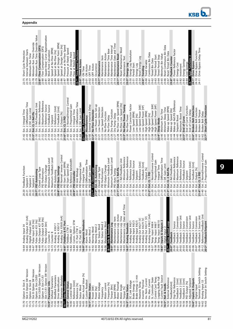
15-7
0O
ptio
n in
Slo
t A
15-7
1Sl
ot A
Opt
ion
SW
Ver
sion
15-7
2O
ptio
n in
Slo
t B
15-7
3Sl
ot B
Opt
ion
SW
Ver
sion
15-7
4O
ptio
n in
Slo
t C0
/E0
15-7
5Sl
ot C
0/E0
Opt
ion
SW
Ver
sion
15-7
6O
ptio
n in
Slo
t C1
/E1
15-7
7Sl
ot C
1/E1
Opt
ion
SW
Ver
sion
15-9
*Pa
ram
eter
Info
15-9
2D
efine
d P
aram
eter
s15
-93
Mod
ified
Par
amet
ers
15-9
8D
rive
Iden
tifica
tion
15-9
9Pa
ram
eter
Met
adat
a16
-**
Dat
a Re
adou
ts16
-0*
Gen
eral
Sta
tus
16-0
0Co
ntro
l Wor
d16
-01
Refe
renc
e [U
nit]
16-0
2Re
fere
nce
[%]
16-0
3St
atus
Wor
d16
-05
Mai
n A
ctua
l Val
ue [%
]16
-09
Cust
om R
eado
ut16
-1*
Mot
or S
tatu
s16
-10
Pow
er [k
W]
16-1
1Po
wer
[hp]
16-1
2M
otor
Vol
tage
16-1
3Fr
eque
ncy
16-1
4M
otor
cur
rent
16-1
5Fr
eque
ncy
[%]
16-1
6To
rque
[Nm
]16
-17
Spee
d [R
PM]
16-1
8M
otor
The
rmal
16-2
0M
otor
Ang
le16
-22
Torq
ue [%
]16
-3*
Driv
e St
atus
16-3
0D
C L
ink
Volta
ge16
-32
Brak
e En
ergy
/s
16-3
3Br
ake
Ener
gy /
2 m
in16
-34
Hea
tsin
k Te
mp.
16-3
5In
vert
er T
herm
al16
-36
Inv.
Nom
. Cur
rent
16-3
7In
v. M
ax. C
urre
nt16
-38
SL C
ontr
olle
r St
ate
16-3
9Co
ntro
l Car
d T
emp.
16-4
0Lo
ggin
g B
uffer
Ful
l16
-49
Curr
ent
Faul
t So
urce
16-5
*Re
f. &
Fee
db.
16-5
0Ex
tern
al R
efer
ence
16-5
2Fe
edba
ck[U
nit]
16-5
3D
igi P
ot R
efer
ence
16-5
4Fe
edba
ck 1
[Uni
t]16
-55
Feed
back
2 [U
nit]
16-5
6Fe
edba
ck 3
[Uni
t]16
-58
PID
Out
put
[%]
16-5
9Ad
just
ed S
etpo
int
16-6
*In
puts
& O
utpu
ts16
-60
Dig
ital I
nput
16-6
1Te
rmin
al 5
3 Sw
itch
Set
ting
16-6
2A
nalo
g In
put
5316
-63
Term
inal
54
Switc
h S
ettin
g
16-6
4A
nalo
g In
put
5416
-65
Ana
log
Out
put
42 [m
A]16
-66
Dig
ital O
utpu
t [b
in]
16-6
7Pu
lse
Inpu
t #2
9 [H
z]16
-68
Puls
e In
put
#33
[Hz]
16-6
9Pu
lse
Out
put
#27
[Hz]
16-7
0Pu
lse
Out
put
#29
[Hz]
16-7
1Re
lay
Out
put
[bin
]16
-72
Coun
ter
A16
-73
Coun
ter
B16
-75
Ana
log
In X
30/1
116
-76
Ana
log
In X
30/1
216
-77
Ana
log
Out
X30
/8 [m
A]16
-8*
Fiel
dbus
& F
C P
ort
16-8
0Fi
eldb
us C
TW 1
16-8
2Fi
eldb
us R
EF 1
16-8
4Co
mm
. Opt
ion
STW
16-8
5FC
Por
t CT
W 1
16-8
6FC
Por
t RE
F 1
16-9
*D
iagn
osis
Rea
dout
s16
-90
Ala
rm W
ord
16-9
1A
larm
Wor
d 2
16-9
2W
arni
ng W
ord
16-9
3W
arni
ng W
ord
216
-94
Ext.
Stat
us W
ord
16-9
5Ex
t. St
atus
Wor
d 2
16-9
6M
aint
enan
ce W
ord
18-*
*In
fo &
Rea
dout
s18
-0*
Mai
nten
ance
Log
18-0
0M
aint
enan
ce L
og: I
tem
18-0
1M
aint
enan
ce L
og: A
ctio
n18
-02
Mai
nten
ance
Log
: Tim
e18
-03
Mai
nten
ance
Log
: Dat
e an
d T
ime
18-3
*A
nalo
g R
eado
uts
18-3
0A
nalo
g In
put
X42/
118
-31
Ana
log
Inpu
t X4
2/3
18-3
2A
nalo
g In
put
X42/
518
-33
Ana
log
Out
X42
/7 [
V]
18-3
4A
nalo
g O
ut X
42/9
[V
]18
-35
Ana
log
Out
X42
/11
[V]
18-3
6A
nalo
g In
put
X48/
2 [m
A]
18-3
7Te
mp.
Inpu
t X4
8/4
18-3
8Te
mp.
Inpu
t X4
8/7
18-3
9Te
mp.
Inpu
t X4
8/10
18-6
*In
puts
& O
utpu
ts 2
18-6
0D
igita
l Inp
ut 2
20-*
*D
rive
Clos
ed L
oop
20-0
*Fe
edba
ck20
-00
Feed
back
1 S
ourc
e20
-01
Feed
back
1 C
onve
rsio
n20
-02
Feed
back
1 S
ourc
e U
nit
20-0
3Fe
edba
ck 2
Sou
rce
20-0
4Fe
edba
ck 2
Con
vers
ion
20-0
5Fe
edba
ck 2
Sou
rce
Uni
t20
-06
Feed
back
3 S
ourc
e20
-07
Feed
back
3 C
onve
rsio
n20
-08
Feed
back
3 S
ourc
e U
nit
20-1
2Re
fere
nce/
Feed
back
Uni
t20
-2*
Feed
back
/Set
poin
t
20-2
0Fe
edba
ck F
unct
ion
20-2
1Se
tpoi
nt 1
20-2
2Se
tpoi
nt 2
20-2
3Se
tpoi
nt 3
20-7
*PI
D A
utot
unin
g20
-70
Clos
ed L
oop
Typ
e20
-71
PID
Per
form
ance
20-7
2PI
D O
utpu
t Ch
ange
20-7
3M
inim
um F
eedb
ack
Leve
l20
-74
Max
imum
Fee
dbac
k Le
vel
20-7
9PI
D A
utot
unin
g20
-8*
PID
Bas
ic S
ettin
gs20
-81
PID
Nor
mal
/ In
vers
e Co
ntro
l20
-82
PID
Sta
rt S
peed
[RPM
]20
-83
PID
Sta
rt S
peed
[Hz]
20-8
4O
n R
efer
ence
Ban
dwid
th20
-9*
PID
Con
trol
ler
20-9
1PI
D A
nti W
indu
p20
-93
PID
Pro
port
iona
l Gai
n20
-94
PID
Inte
gral
Tim
e20
-95
PID
Diff
eren
tiatio
n T
ime
20-9
6PI
D D
iff. G
ain
Lim
it21
-**
Ext.
Clo
sed
Loo
p21
-0*
Ext.
CL
Aut
otun
ing
21-0
0Cl
osed
Loo
p T
ype
21-0
1PI
D P
erfo
rman
ce21
-02
PID
Out
put
Chan
ge21
-03
Min
imum
Fee
dbac
k Le
vel
21-0
4M
axim
um F
eedb
ack
Leve
l21
-09
PID
Aut
o T
unin
g21
-1*
Ext.
CL
1 Re
f./Fb
.21
-10
Ext.
1 Re
f./Fe
edba
ck U
nit
21-1
1Ex
t. 1
Min
imum
Ref
eren
ce21
-12
Ext.
1 M
axim
um R
efer
ence
21-1
3Ex
t. 1
Refe
renc
e So
urce
21-1
4Ex
t. 1
Feed
back
Sou
rce
21-1
5Ex
t. 1
Setp
oint
21-1
7Ex
t. 1
Refe
renc
e [U
nit]
21-1
8Ex
t. 1
Feed
back
[Uni
t]21
-19
Ext.
1 O
utpu
t [%
]21
-2*
Ext.
CL
1 PI
D21
-20
Ext.
1 N
orm
al/In
vers
e Co
ntro
l21
-21
Ext.
1 Pr
opor
tiona
l Gai
n21
-22
Ext.
1 In
tegr
al T
ime
21-2
3Ex
t. 1
Diff
eren
tatio
n T
ime
21-2
4Ex
t. 1
Dif.
Gai
n L
imit
21-3
*Ex
t. C
L 2
Ref./
Fb.
21-3
0Ex
t. 2
Ref./
Feed
back
Uni
t21
-31
Ext.
2 M
inim
um R
efer
ence
21-3
2Ex
t. 2
Max
imum
Ref
eren
ce21
-33
Ext.
2 Re
fere
nce
Sour
ce21
-34
Ext.
2 Fe
edba
ck S
ourc
e21
-35
Ext.
2 Se
tpoi
nt21
-37
Ext.
2 Re
fere
nce
[Uni
t]21
-38
Ext.
2 Fe
edba
ck [U
nit]
21-3
9Ex
t. 2
Out
put
[%]
21-4
*Ex
t. C
L 2
PID
21-4
0Ex
t. 2
Nor
mal
/Inve
rse
Cont
rol
21-4
1Ex
t. 2
Prop
ortio
nal G
ain
21-4
2Ex
t. 2
Inte
gral
Tim
e21
-43
Ext.
2 D
iffer
enta
tion
Tim
e21
-44
Ext.
2 D
if. G
ain
Lim
it21
-5*
Ext.
CL
3 Re
f./Fb
.21
-50
Ext.
3 R
ef./F
eedb
ack
Uni
t21
-51
Ext.
3 M
inim
um R
efer
ence
21-5
2Ex
t. 3
Max
imum
Ref
eren
ce21
-53
Ext.
3 R
efer
ence
Sou
rce
21-5
4Ex
t. 3
Fee
dbac
k So
urce
21-5
5Ex
t. 3
Set
poin
t21
-57
Ext.
3 R
efer
ence
[Uni
t]21
-58
Ext.
3 F
eedb
ack
[Uni
t]21
-59
Ext.
3 O
utpu
t [%
]21
-6*
Ext.
CL
3 PI
D21
-60
Ext.
3 N
orm
al/In
vers
e Co
ntro
l21
-61
Ext.
3 P
ropo
rtio
nal G
ain
21-6
2Ex
t. 3
Inte
gral
Tim
e21
-63
Ext.
3 D
iffer
enta
tion
Tim
e21
-64
Ext.
3 D
if. G
ain
Lim
it22
-**
App
l. Fu
nctio
ns22
-0*
Mis
cella
neou
s22
-00
Exte
rnal
Inte
rlock
Del
ay22
-2*
No-
Flow
Det
ectio
n22
-20
Low
Pow
er A
uto
Set
-up
22-2
1Lo
w P
ower
Det
ectio
n22
-22
Low
Spe
ed D
etec
tion
22-2
3N
o-Fl
ow F
unct
ion
22-2
4N
o-Fl
ow D
elay
22-2
6D
ry P
ump
Fun
ctio
n22
-27
Dry
Pum
p D
elay
22-2
8N
o-Fl
ow L
ow S
peed
[RPM
]22
-29
No-
Flow
Low
Spe
ed [H
z]22
-3*
No-
Flow
Pow
er T
unin
g22
-30
No-
Flow
Pow
er22
-31
Pow
er C
orre
ctio
n F
acto
r22
-32
Low
Spe
ed [R
PM]
22-3
3Lo
w S
peed
[Hz]
22-3
4Lo
w S
peed
Pow
er [k
W]
22-3
5Lo
w S
peed
Pow
er [H
P]22
-36
Hig
h S
peed
[RPM
]22
-37
Hig
h S
peed
[Hz]
22-3
8H
igh
Spe
ed P
ower
[kW
]22
-39
Hig
h S
peed
Pow
er [H
P]22
-4*
Slee
p M
ode
22-4
0M
inim
um R
un T
ime
22-4
1M
inim
um S
leep
Tim
e22
-42
Wak
e-up
Spe
ed [R
PM]
22-4
3W
ake-
up S
peed
[Hz]
22-4
4W
ake-
up R
ef./F
B D
iffer
ence
22-4
5Se
tpoi
nt B
oost
22-4
6M
axim
um B
oost
Tim
e22
-5*
End
of
Curv
e22
-50
End
of
Curv
e Fu
nctio
n22
-51
End
of
Curv
e D
elay
22-6
*Br
oken
Bel
t D
etec
tion
22-6
0Br
oken
Bel
t Fu
nctio
n22
-61
Brok
en B
elt
Torq
ue22
-62
Brok
en B
elt
Del
ay22
-7*
Shor
t Cy
cle
Prot
ectio
n
22-7
5Sh
ort
Cycl
e Pr
otec
tion
22-7
6In
terv
al b
etw
een
Sta
rts
22-7
7M
inim
um R
un T
ime
22-7
8M
inim
um R
un T
ime
Ove
rrid
e22
-79
Min
imum
Run
Tim
e O
verr
ide
Valu
e22
-8*
Flow
Com
pens
atio
n (D
FS)
22-8
0Fl
ow C
ompe
nsat
ion
(DFS
)22
-81
Squa
re-li
near
Cur
ve A
ppro
xim
atio
n22
-82
Wor
k Po
int
Calc
ulat
ion
22-8
3Sp
eed
at
No-
Flow
[RPM
]22
-84
Spee
d a
t N
o-Fl
ow [H
z]22
-85
Spee
d a
t D
esig
n P
oint
[RPM
]22
-86
Spee
d a
t D
esig
n P
oint
[Hz]
22-8
7Pr
essu
re a
t N
o-Fl
ow S
peed
22-8
8Pr
essu
re a
t Ra
ted
Spe
ed22
-89
Flow
at
Des
ign
Poi
nt22
-90
Flow
at
Rate
d S
peed
23-*
*Ti
me-
base
d F
unct
ions
23-0
*Ti
med
Act
ions
23-0
0O
N T
ime
23-0
1O
N A
ctio
n23
-02
OFF
Tim
e23
-03
OFF
Act
ion
23-0
4O
ccur
renc
e23
-1*
Mai
nten
ance
23-1
0M
aint
enan
ce It
em23
-11
Mai
nten
ance
Act
ion
23-1
2M
aint
enan
ce T
ime
Base
23-1
3M
aint
enan
ce T
ime
Inte
rval
23-1
4M
aint
enan
ce D
ate
and
Tim
e23
-1*
Mai
nten
ance
Res
et23
-15
Rese
t M
aint
enan
ce W
ord
23-1
6M
aint
enan
ce T
ext
23-5
*En
ergy
Log
23-5
0En
ergy
Log
Res
olut
ion
23-5
1Pe
riod
Sta
rt23
-53
Ener
gy L
og23
-54
Rese
t En
ergy
Log
23-6
*Tr
endi
ng23
-60
Tren
d V
aria
ble
23-6
1Co
ntin
uous
Bin
Dat
a23
-62
Tim
ed B
in D
ata
23-6
3Ti
med
Per
iod
Sta
rt23
-64
Tim
ed P
erio
d S
top
23-6
5M
inim
um B
in V
alue
23-6
6Re
set
Cont
inuo
us B
in D
ata
23-6
7Re
set
Tim
ed B
in D
ata
23-8
*Pa
ybac
k Co
unte
r23
-80
Pow
er R
efer
ence
Fac
tor
23-8
1En
ergy
Cos
t23
-82
Inve
stm
ent
23-8
3En
ergy
Sav
ings
23-8
4Co
st S
avin
gs24
-**
App
l. Fu
nctio
ns 2
24-1
*D
rive
Bypa
ss24
-10
Driv
e By
pass
Fun
ctio
n24
-11
Driv
e By
pass
Del
ay T
ime
Appendix
MG21H202 4073.8/02-EN All rights reserved. 81
9 9
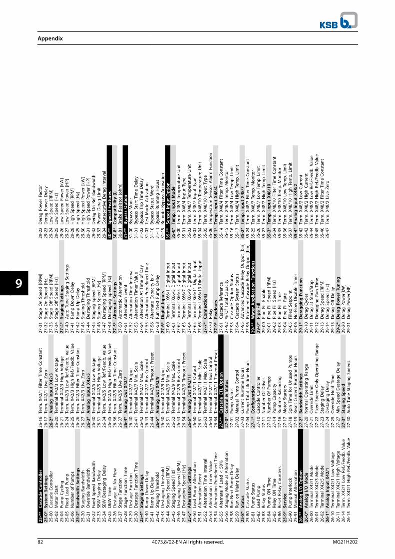
25-*
*Ca
scad
e Co
ntro
ller
25-0
*Sy
stem
Set
tings
25-0
0Ca
scad
e Co
ntro
ller
25-0
2M
otor
Sta
rt25
-04
Pum
p C
yclin
g25
-05
Fixe
d L
ead
Pum
p25
-06
Num
ber
of P
umps
25-2
*Ba
ndw
idth
Set
tings
25-2
0St
agin
g B
andw
idth
25-2
1O
verr
ide
Band
wid
th25
-22
Fixe
d S
peed
Ban
dwid
th25
-23
SBW
Sta
ging
Del
ay25
-24
SBW
Des
tagi
ng D
elay
25-2
5O
BW T
ime
25-2
6D
esta
ge A
t N
o-Fl
ow25
-27
Stag
e Fu
nctio
n25
-28
Stag
e Fu
nctio
n T
ime
25-2
9D
esta
ge F
unct
ion
25-3
0D
esta
ge F
unct
ion
Tim
e25
-4*
Stag
ing
Set
tings
25-4
0Ra
mp
Dow
n D
elay
25-4
1Ra
mp
Up
Del
ay25
-42
Stag
ing
Thr
esho
ld25
-43
Des
tagi
ng T
hres
hold
25-4
4St
agin
g S
peed
[RPM
]25
-45
Stag
ing
Spe
ed [H
z]25
-46
Des
tagi
ng S
peed
[RPM
]25
-47
Des
tagi
ng S
peed
[Hz]
25-5
*A
ltern
atio
n S
ettin
gs25
-50
Lead
Pum
p A
ltern
atio
n25
-51
Alte
rnat
ion
Eve
nt25
-52
Alte
rnat
ion
Tim
e In
terv
al25
-53
Alte
rnat
ion
Tim
er V
alue
25-5
4A
ltern
atio
n P
rede
fined
Tim
e25
-55
Alte
rnat
e if
Load
< 5
0%25
-56
Stag
ing
Mod
e at
Alte
rnat
ion
25-5
8Ru
n N
ext
Pum
p D
elay
25-5
9Ru
n o
n M
ains
Del
ay25
-8*
Stat
us25
-80
Casc
ade
Stat
us25
-81
Pum
p S
tatu
s25
-82
Lead
Pum
p25
-83
Rela
y St
atus
25-8
4Pu
mp
ON
Tim
e25
-85
Rela
y O
N T
ime
25-8
6Re
set
Rela
y Co
unte
rs25
-9*
Serv
ice
25-9
0Pu
mp
Inte
rlock
25-9
1M
anua
l Alte
rnat
ion
26-*
*A
nalo
g I/
O O
ptio
n26
-0*
Ana
log
I/O
Mod
e26
-00
Term
inal
X42
/1 M
ode
26-0
1Te
rmin
al X
42/3
Mod
e26
-02
Term
inal
X42
/5 M
ode
26-1
*A
nalo
g In
put
X42/
126
-10
Term
inal
X42
/1 L
ow V
olta
ge26
-11
Term
inal
X42
/1 H
igh
Vol
tage
26-1
4Te
rm. X
42/1
Low
Ref
./Fee
db. V
alue
26-1
5Te
rm. X
42/1
Hig
h R
ef./F
eedb
. Val
ue
26-1
6Te
rm. X
42/1
Filt
er T
ime
Cons
tant
26-1
7Te
rm. X
42/1
Liv
e Ze
ro26
-2*
Ana
log
Inpu
t X4
2/3
26-2
0Te
rmin
al X
42/3
Low
Vol
tage
26-2
1Te
rmin
al X
42/3
Hig
h V
olta
ge26
-24
Term
. X42
/3 L
ow R
ef./F
eedb
. Val
ue26
-25
Term
. X42
/3 H
igh
Ref
./Fee
db. V
alue
26-2
6Te
rm. X
42/3
Filt
er T
ime
Cons
tant
26-2
7Te
rm. X
42/3
Liv
e Ze
ro26
-3*
Ana
log
Inpu
t X4
2/5
26-3
0Te
rmin
al X
42/5
Low
Vol
tage
26-3
1Te
rmin
al X
42/5
Hig
h V
olta
ge26
-34
Term
. X42
/5 L
ow R
ef./F
eedb
. Val
ue26
-35
Term
. X42
/5 H
igh
Ref
./Fee
db. V
alue
26-3
6Te
rm. X
42/5
Filt
er T
ime
Cons
tant
26-3
7Te
rm. X
42/5
Liv
e Ze
ro26
-4*
Ana
log
Out
X42
/726
-40
Term
inal
X42
/7 O
utpu
t26
-41
Term
inal
X42
/7 M
in. S
cale
26-4
2Te
rmin
al X
42/7
Max
. Sca
le26
-43
Term
inal
X42
/7 B
us C
ontr
ol26
-44
Term
inal
X42
/7 T
imeo
ut P
rese
t26
-5*
Ana
log
Out
X42
/926
-50
Term
inal
X42
/9 O
utpu
t26
-51
Term
inal
X42
/9 M
in. S
cale
26-5
2Te
rmin
al X
42/9
Max
. Sca
le26
-53
Term
inal
X42
/9 B
us C
ontr
ol26
-54
Term
inal
X42
/9 T
imeo
ut P
rese
t26
-6*
Ana
log
Out
X42
/11
26-6
0Te
rmin
al X
42/1
1 O
utpu
t26
-61
Term
inal
X42
/11
Min
. Sca
le26
-62
Term
inal
X42
/11
Max
. Sca
le26
-63
Term
inal
X42
/11
Bus
Cont
rol
26-6
4Te
rmin
al X
42/1
1 Ti
meo
ut P
rese
t27
-**
Casc
ade
CTL
Opt
ion
27-0
*Co
ntro
l & S
tatu
s27
-01
Pum
p S
tatu
s27
-02
Man
ual P
ump
Con
trol
27-0
3Cu
rren
t Ru
ntim
e H
ours
27-0
4Pu
mp
Tot
al L
ifetim
e H
ours
27-1
*Co
nfigu
ratio
n27
-10
Casc
ade
Cont
rolle
r27
-11
Num
ber
Of
Driv
es27
-12
Num
ber
Of
Pum
ps27
-14
Pum
p C
apac
ity27
-16
Runt
ime
Bala
ncin
g27
-17
Mot
or S
tart
ers
27-1
8Sp
in T
ime
for
Unu
sed
Pum
ps27
-19
Rese
t Cu
rren
t Ru
ntim
e H
ours
27-2
*Ba
ndw
idth
Set
tings
27-2
0N
orm
al O
pera
ting
Ran
ge27
-21
Ove
rrid
e Li
mit
27-2
2Fi
xed
Spe
ed O
nly
Ope
ratin
g R
ange
27-2
3St
agin
g D
elay
27-2
4D
esta
ging
Del
ay27
-25
Ove
rrid
e H
old
Tim
e27
-27
Min
Spe
ed D
esta
ge D
elay
27-3
*St
agin
g S
peed
27-3
0Au
to T
une
Stag
ing
Spe
eds
27-3
1St
age
On
Spe
ed [R
PM]
27-3
2St
age
On
Spe
ed [H
z]27
-33
Stag
e O
ff S
peed
[RPM
]27
-34
Stag
e O
ff S
peed
[Hz]
27-4
*St
agin
g S
ettin
gs27
-40
Auto
Tun
e St
agin
g S
ettin
gs27
-41
Ram
p D
own
Del
ay27
-42
Ram
p U
p D
elay
27-4
3St
agin
g T
hres
hold
27-4
4D
esta
ging
Thr
esho
ld27
-45
Stag
ing
Spe
ed [R
PM]
27-4
6St
agin
g S
peed
[Hz]
27-4
7D
esta
ging
Spe
ed [R
PM]
27-4
8D
esta
ging
Spe
ed [H
z]27
-5*
Alte
rnat
e Se
ttin
gs27
-50
Auto
mat
ic A
ltern
atio
n27
-51
Alte
rnat
ion
Eve
nt27
-52
Alte
rnat
ion
Tim
e In
terv
al27
-53
Alte
rnat
ion
Tim
er V
alue
27-5
4Al
tern
atio
n A
t Ti
me
of D
ay27
-55
Alte
rnat
ion
Pre
defin
ed T
ime
27-5
6Al
tern
ate
Capa
city
is <
27-5
8Ru
n N
ext
Pum
p D
elay
27-6
*D
igita
l Inp
uts
27-6
0Te
rmin
al X
66/1
Dig
ital I
nput
27-6
1Te
rmin
al X
66/3
Dig
ital I
nput
27-6
2Te
rmin
al X
66/5
Dig
ital I
nput
27-6
3Te
rmin
al X
66/7
Dig
ital I
nput
27-6
4Te
rmin
al X
66/9
Dig
ital I
nput
27-6
5Te
rmin
al X
66/1
1 D
igita
l Inp
ut27
-66
Term
inal
X66
/13
Dig
ital I
nput
27-7
*Co
nnec
tions
27-7
0Re
lay
27-9
*Re
adou
ts27
-91
Casc
ade
Refe
renc
e27
-92
% O
f To
tal C
apac
ity27
-93
Casc
ade
Opt
ion
Sta
tus
27-9
4Ca
scad
e Sy
stem
Sta
tus
27-9
5Ad
vanc
ed C
asca
de R
elay
Out
put
[bin
]27
-96
Exte
nded
Cas
cade
Rel
ay O
utpu
t [b
in]
29-*
*W
ater
App
licat
ion
Fun
ctio
ns29
-0*
Pipe
Fill
29-0
0Pi
pe F
ill E
nabl
e29
-01
Pipe
Fill
Spe
ed [R
PM]
29-0
2Pi
pe F
ill S
peed
[Hz]
29-0
3Pi
pe F
ill T
ime
29-0
4Pi
pe F
ill R
ate
29-0
5Fi
lled
Set
poin
t29
-06
No-
Flow
Dis
able
Tim
er29
-1*
Der
aggi
ng F
unct
ion
29-1
0D
erag
Cyc
les
29-1
1D
erag
at
Star
t/St
op29
-12
Der
aggi
ng R
un T
ime
29-1
3D
erag
Spe
ed [R
PM]
29-1
4D
erag
Spe
ed [H
z]29
-15
Der
ag O
ff D
elay
29-2
*D
erag
Pow
er T
unin
g29
-20
Der
ag P
ower
[kW
]29
-21
Der
ag P
ower
[HP]
29-2
2D
erag
Pow
er F
acto
r29
-23
Der
ag P
ower
Del
ay29
-24
Low
Spe
ed [R
PM]
29-2
5Lo
w S
peed
[Hz]
29-2
6Lo
w S
peed
Pow
er [k
W]
29-2
7Lo
w S
peed
Pow
er [H
P]29
-28
Hig
h S
peed
[RPM
]29
-29
Hig
h S
peed
[Hz]
29-3
0H
igh
Spe
ed P
ower
[kW
]29
-31
Hig
h S
peed
Pow
er [H
P]29
-32
Der
ag O
n R
ef B
andw
idth
29-3
3Po
wer
Der
ag L
imit
29-3
4Co
nsec
utiv
e D
erag
Inte
rval
30-*
*Sp
ecia
l Fea
ture
s30
-8*
Com
patib
ility
(I)
30-8
1Br
ake
Resi
stor
(ohm
)31
-**
Bypa
ss O
ptio
n31
-00
Bypa
ss M
ode
31-0
1By
pass
Sta
rt T
ime
Del
ay31
-02
Bypa
ss T
rip T
ime
Del
ay31
-03
Test
Mod
e Ac
tivat
ion
31-1
0By
pass
Sta
tus
Wor
d31
-11
Bypa
ss R
unni
ng H
ours
31-1
9Re
mot
e By
pass
Act
ivat
ion
35-*
*Se
nsor
Inpu
t O
ptio
n35
-0*
Tem
p. In
put
Mod
e35
-00
Term
. X48
/4 T
empe
ratu
re U
nit
35-0
1Te
rm. X
48/4
Inpu
t Ty
pe35
-02
Term
. X48
/7 T
empe
ratu
re U
nit
35-0
3Te
rm. X
48/7
Inpu
t Ty
pe35
-04
Term
. X48
/10
Tem
pera
ture
Uni
t35
-05
Term
. X48
/10
Inpu
t Ty
pe35
-06
Tem
pera
ture
Sen
sor
Ala
rm F
unct
ion
35-1
*Te
mp.
Inpu
t X4
8/4
35-1
4Te
rm. X
48/4
Filt
er T
ime
Cons
tant
35-1
5Te
rm. X
48/4
Tem
p. M
onito
r35
-16
Term
. X48
/4 L
ow T
emp.
Lim
it35
-17
Term
. X48
/4 H
igh
Tem
p. L
imit
35-2
*Te
mp.
Inpu
t X4
8/7
35-2
4Te
rm. X
48/7
Filt
er T
ime
Cons
tant
35-2
5Te
rm. X
48/7
Tem
p. M
onito
r35
-26
Term
. X48
/7 L
ow T
emp.
Lim
it35
-27
Term
. X48
/7 H
igh
Tem
p. L
imit
35-3
*Te
mp.
Inpu
t X4
8/10
35-3
4Te
rm. X
48/1
0 Fi
lter
Tim
e Co
nsta
nt35
-35
Term
. X48
/10
Tem
p. M
onito
r35
-36
Term
. X48
/10
Low
Tem
p. L
imit
35-3
7Te
rm. X
48/1
0 H
igh
Tem
p. L
imit
35-4
*A
nalo
g In
put
X48/
235
-42
Term
. X48
/2 L
ow C
urre
nt35
-43
Term
. X48
/2 H
igh
Cur
rent
35-4
4Te
rm. X
48/2
Low
Ref
./Fee
db. V
alue
35-4
5Te
rm. X
48/2
Hig
h R
ef./F
eedb
. Val
ue35
-46
Term
. X48
/2 F
ilter
Tim
e Co
nsta
nt35
-47
Term
. X48
/2 L
ive
Zero
Appendix
82 4073.8/02-EN All rights reserved. MG21H202
99

Index
AAbbreviation........................................................................................... 78
ACinput.................................................................................................. 0mains................................................................................................. 0waveform......................................................................................... 0
AC input................................................................................................... 17
AC mains.................................................................................................. 17
Additional resources.............................................................................. 4
Alarm log................................................................................................. 23
Alarms....................................................................................................... 38
AMA............................................................................................. 36, 40, 43
Ambient conditions............................................................................. 65
Analog input............................................................................. 18, 39, 66
Analog output................................................................................ 18, 66
Analog signal......................................................................................... 39
Analog speed reference..................................................................... 33
Approval..................................................................................................... 8
Auto on................................................................................ 24, 31, 36, 38
Automatic energy optimisation...................................................... 29
Automatic motor adaptation........................................................... 29
Auto-reset................................................................................................ 22
Auxiliary equipment............................................................................ 21
BBack plate................................................................................................ 12
Braking.............................................................................................. 36, 41
CCable
routing................................................................................................. 21Motor cable.......................................................................... 13, 16, 63Motor cable length.......................................................................... 65Specifications.................................................................................... 65
Certification............................................................................................... 8
Circuit breaker.................................................................. 21, 69, 70, 71
Clearance requirements..................................................................... 11
Closed loop............................................................................................. 19
Communication option...................................................................... 42
Conduct................................................................................................... 21
Controlcharacteristic..................................................................................... 68
Control cardControl card....................................................................................... 39Control card performance............................................................ 68Control card, 10 V DC output....................................................... 68Control card, 24 V DC output....................................................... 67Control card, RS485 serial communication............................. 65USB serial communication............................................................ 68
Control signal......................................................................................... 36
Control terminal............................................................... 24, 26, 36, 38
Control wiring................................................................... 13, 15, 19, 21
Convention............................................................................................. 78
Cooling.............................................................................................. 11, 63
Cooling clearance................................................................................. 21
Cos φ.................................................................................................. 64, 67
Currentlevel....................................................................................................... 66limit....................................................................................................... 47mode.................................................................................................... 66range..................................................................................................... 66rating.................................................................................................... 40DC current................................................................................ 0 , 13Input current...................................................................................... 17Output current.................................................................................. 37
DDC current............................................................................................... 37
DC link....................................................................................................... 39
Default setting....................................................................................... 24
DeratingDerating............................................................................................... 65
Digital input................................................................ 18, 19, 38, 40, 66
Digital output......................................................................................... 67
Dimensions...................................................................................... 76, 77
Discharge time......................................................................................... 9
Disconnect switch................................................................................ 22
Displacement power factor.............................................................. 64
EEfficiency........................................................................................... 63, 65
Electrical interference......................................................................... 13
EMC............................................................................................................ 13
EMC interference.................................................................................. 15
Environment........................................................................................... 65
Exploded view..................................................................................... 6, 7
External alarm reset............................................................................. 34
External command................................................................ 0 , 8, 38
External controllers................................................................................ 4
External interlock.................................................................................. 34
Index
MG21H202 4073.8/02-EN All rights reserved. 83
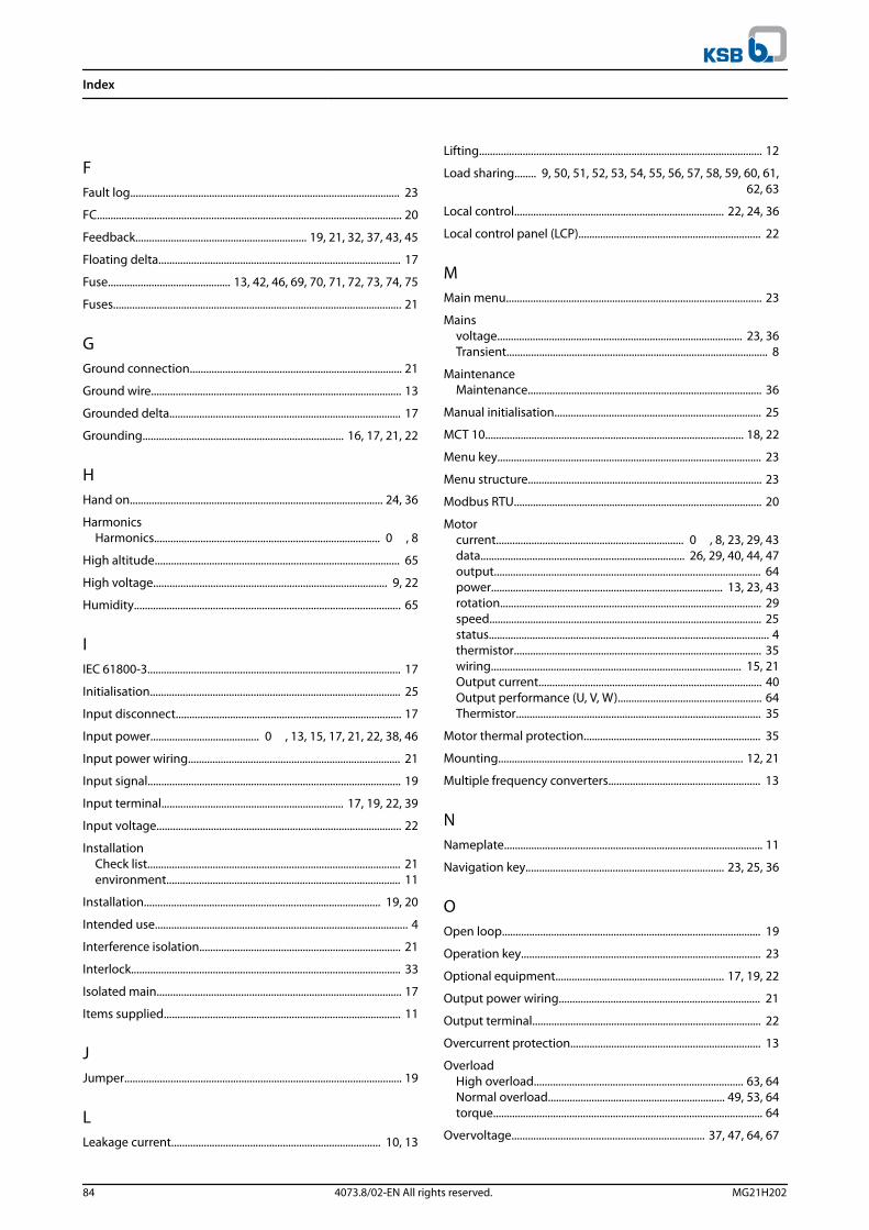
FFault log................................................................................................... 23
FC................................................................................................................ 20
Feedback............................................................... 19, 21, 32, 37, 43, 45
Floating delta......................................................................................... 17
Fuse............................................. 13, 42, 46, 69, 70, 71, 72, 73, 74, 75
Fuses.......................................................................................................... 21
GGround connection.............................................................................. 21
Ground wire............................................................................................ 13
Grounded delta..................................................................................... 17
Grounding.......................................................................... 16, 17, 21, 22
HHand on............................................................................................. 24, 36
HarmonicsHarmonics................................................................................... 0 , 8
High altitude.......................................................................................... 65
High voltage...................................................................................... 9, 22
Humidity.................................................................................................. 65
IIEC 61800-3............................................................................................. 17
Initialisation............................................................................................ 25
Input disconnect................................................................................... 17
Input power........................................ 0 , 13, 15, 17, 21, 22, 38, 46
Input power wiring.............................................................................. 21
Input signal............................................................................................. 19
Input terminal................................................................... 17, 19, 22, 39
Input voltage.......................................................................................... 22
InstallationCheck list............................................................................................. 21environment...................................................................................... 11
Installation....................................................................................... 19, 20
Intended use............................................................................................. 4
Interference isolation.......................................................................... 21
Interlock................................................................................................... 33
Isolated main.......................................................................................... 17
Items supplied....................................................................................... 11
JJumper...................................................................................................... 19
LLeakage current............................................................................. 10, 13
Lifting........................................................................................................ 12
Load sharing........ 9, 50, 51, 52, 53, 54, 55, 56, 57, 58, 59, 60, 61,62, 63
Local control............................................................................. 22, 24, 36
Local control panel (LCP)................................................................... 22
MMain menu.............................................................................................. 23
Mainsvoltage.......................................................................................... 23, 36Transient................................................................................................ 8
MaintenanceMaintenance...................................................................................... 36
Manual initialisation............................................................................ 25
MCT 10............................................................................................... 18, 22
Menu key................................................................................................. 23
Menu structure...................................................................................... 23
Modbus RTU........................................................................................... 20
Motorcurrent..................................................................... 0 , 8, 23, 29, 43data........................................................................... 26, 29, 40, 44, 47output.................................................................................................. 64power..................................................................................... 13, 23, 43rotation................................................................................................ 29speed.................................................................................................... 25status....................................................................................................... 4thermistor........................................................................................... 35wiring............................................................................................ 15, 21Output current.................................................................................. 40Output performance (U, V, W)..................................................... 64Thermistor.......................................................................................... 35
Motor thermal protection................................................................. 35
Mounting.......................................................................................... 12, 21
Multiple frequency converters........................................................ 13
NNameplate............................................................................................... 11
Navigation key......................................................................... 23, 25, 36
OOpen loop............................................................................................... 19
Operation key........................................................................................ 23
Optional equipment.............................................................. 17, 19, 22
Output power wiring.......................................................................... 21
Output terminal.................................................................................... 22
Overcurrent protection...................................................................... 13
OverloadHigh overload............................................................................. 63, 64Normal overload................................................................. 49, 53, 64torque................................................................................................... 64
Overvoltage....................................................................... 37, 47, 64, 67
Index
84 4073.8/02-EN All rights reserved. MG21H202

PParameter Menu Structure................................................................ 79
PELV............................................................................... 35, 65, 66, 67, 68
Phase loss................................................................................................ 39
PM Motor................................................................................................. 27
Potential equalisation......................................................................... 13
Potentiometer........................................................................................ 33
Power connection................................................................................ 13
Power factor.......................................................................... 0 , 21, 64
Programming............................................................. 19, 22, 23, 24, 39
Pulse input.............................................................................................. 67
QQualified personnel................................................................................ 9
Quick menu............................................................................................ 23
RRamp-down time.................................................................................. 47
Ramp-up time........................................................................................ 47
Reference................................................................................... 23, 36, 37
ReferenceReference............................................................................................ 32
RelayRelay..................................................................................................... 181.............................................................................................................. 672.............................................................................................................. 67output.................................................................................................. 67
Remote commands................................................................................ 4
Remote reference................................................................................. 37
Reset................................................................ 22, 23, 24, 25, 38, 40, 45
RFI filter.................................................................................................... 17
RMS current......................................................................................... 0
RS485........................................................................................................ 35
RS485 serial communication............................................................ 20
Run command....................................................................................... 31
Run permissive............................................................................... 34, 37
Run/Stop command............................................................................ 33
SSafe torque off....................................................................................... 20
Safety........................................................................................................ 10
Screened cable............................................................................... 15, 21
Serial communication............................................. 18, 24, 36, 37, 38
Service...................................................................................................... 36
Setpoint.................................................................................................... 38
Set-up....................................................................................................... 31
Shock......................................................................................................... 11
Short circuit............................................................................................ 41
Sleep mode............................................................................................. 38
SmartStart............................................................................................... 25
Specifications......................................................................................... 20
Speed reference............................................................... 19, 31, 33, 36
Start-up.................................................................................................... 25
Status display......................................................................................... 36
Status mode........................................................................................... 36
STO............................................................................................................. 20
Storage.............................................................................................. 11, 65
Supply voltage.................................................................. 17, 18, 22, 42
Switch....................................................................................................... 19
Switching frequency........................................................................... 37
Symbol...................................................................................................... 78
System feedback..................................................................................... 4
TTerminal 53............................................................................................. 19
Terminal 54............................................................................................. 19
Terminal tightening torques............................................................. 68
Thermal protection................................................................................ 8
Thermistor........................................................................................ 17, 40
Thermistor control wiring.................................................................. 17
TorqueStarting torque.................................................................................. 64characteristic..................................................................................... 64limit....................................................................................................... 47
Transient protection......................................................................... 0
TripTrip.................................................................................................. 35, 38level......................................................................................... 69, 70, 71lock........................................................................................................ 38
Troubleshooting................................................................................... 48
True power factor................................................................................. 64
UUL compliance....................................................................................... 72
Unintended motor rotation.............................................................. 10
Unintended start.............................................................................. 9, 36
VVibration.................................................................................................. 11
Voltage imbalance............................................................................... 39
Voltage level........................................................................................... 66
VVC+.......................................................................................................... 27
Index
MG21H202 4073.8/02-EN All rights reserved. 85

WWarnings.................................................................................................. 38
Weight............................................................................................... 76, 77
Windmilling............................................................................................ 10
Wire size............................................................................................ 13, 16
Wiring schematic.................................................................................. 14
Index
86 4073.8/02-EN All rights reserved. MG21H202

Index
MG21H202 4073.8/02-EN All rights reserved. 87

4073
.8/0
2-E
N
KSB Aktiengesellschaft
202H12GM 1450R031
*MG21H202*
PumpDrive R (KSB202)
Motor-independent Frequency Converterfor centrifugal pumps
Operating range 0.25-90 kW
Installation/Operating Manual