installation/owner’s manual model 9050model 9050
TRANSCRIPT
Installation/Owner’s Manual Model 9050Model 9050Model 9050
Copyright 2009 DoorKing, Inc. All rights reserved.
Copyright 2017 DoorKing, Inc. All rights reserved.
Use this manual for circuit board 4702-010 Revision AA or higher.
Date Installed:
Installer/Company Name:
Phone Number:
Leave Manual with Owner
Vehicular Slide Gate Operator
UL 325 Compliant
Circuit BoardSerial Numberand Revision Letter:
WARNING
MOVING GATE CAN CAUSE
Operate gate only when gate area is in sight
and free of people and obstructions.
Do not allow children to play in gate area
or operate gate.Do not stand in gate path or walk through
path while gate is moving.
Read owner’s manual and safety instructions.
SERIOUS INJURY OR DEATH
CLASS
CERTIFIED TO
CAN/CSA C22.2 NO. 247
CONFORMS TO
ANSI/UL-325
VEHICULAR GATE OPERATORHP
53382
MODELSERIALVOLTS
PHASE
AMPS
60 Hz
MAX GATE LOADDoorKing, Inc., Inglewood, CA
EXTERNAL ENTRAPMENT PROTECTION MUST be installed or the gate operator WILL NOT function.
THIS PRODUCT IS TO BE INSTALLED AND SERVICED BY A TRAINED GATE SYSTEMS TECHNICIAN ONLY. Visit www.dkslocator.com to find a professional installing and servicing dealer in your area.
9050-065-A-1-17

9050-065-A-1-172 Quick Guide - 1
QUICK GUIDE: DIP-Switches
Whenever a switch setting is changed, power MUST be cycled to the operator.
Every time the operator is powered up, the First open command will automatically run “Multiple gate cycles” that will locate and remember the gate’s open and close positions (See page 20).
7-OFF7-OFF7-ON7-ON
8-OFF8-ON
8-OFF8-ON
Gate CloseBack-OffPosition
Gate OpenBack-OffPosition
Normal Setting. Gate fully opens. Gate stops short 1” from full open position. Used for a reversing edge device.Gate stops short 2” from full open position. Used for a reversing edge device. Gate stops short 3” from full open position. Used for a reversing edge device.
Switch 1 Must OPEN the gate upon initial AC power up and open command. If the first open command begins to close the gate, turn AC power off and reverse this switch. Opening direction will vary depending on the chain setup position (See above).
Switch 2 Turns the auto-close timer on or off. Can be adjusted from 1 to 23 seconds to close gate.
Switch 3 This switch determines when the relay on the board will be activated. This relay can be used as a switch for various functions such as illuminating a warning light when the gate is not closed, or turning on a green light when the gate is full open.
Switch 4 This switch determines the operation of the built-in solenoid lock. The OFF setting is the factory setup. Caution: Do not set this switch to ON unless the 2600-862 fail-secure manual release kit has been installed in the operator. Changing this switch to the ON setting without installing the lock kit will damage the operator. See pages 31 and 32 for more information about Fail-Safe vs. Fail-Secure release systems.
Switches 5-6 These work in conjunction with each other and determine if the operator will stop the gate at the full open position, or if the gate should stop 1, 2 or 3 inches short of the full open position. Needed only when using a reversing edge entrapment protection device on the opening edge of the gate with an end post as the physical stop.
Switches 7-8 These work in conjunction with each other and determine if the operator will stop the gate at the full close position, or if the gate should stop 1, 2 or 3 inches short of the full close position. Needed only when using a reversing edge entrapment protection device on the closing edge of the gate with an end post as the physical stop.
Switch Function Setting Description
OFFON
5-OFF5-OFF5-ON5-ON
6-OFF6-ON
6-OFF6-ON
Auto-CloseTimer2
1
Relay OFFON
3
4
5 and 6
7 and 8
Relay is activated when gate is full open.Relay is activated when gate is not closed.
Auto-close timer is OFF. Manual input required to close gate.Auto-close timer is ON. Adjustable from 1-23 seconds to close gate.
OFF
ON
Built-InSolenoid Lock
See Page 31-32
Normal Setting. Fail-Safe (Factory Set). Lock engages only when an attempt is made to manually force the gate open.
Fail-Secure. Lock engages after each cycle. CAUTION: Do not use this setting unless the 2600-862 manual release kit has been installed or damage will occur to operator.
Normal Setting. Gate fully closes. Gate stops short 1” from full close position. Used for a reversing edge device.Gate stops short 2” from full close position. Used for a reversing edge device. Gate stops short 3” from full close position. Used for a reversing edge device.
Changes the direction the operator will open/close the gate depending on the different chain configurations.
Openingdirection
using OFFsetting.
Openingdirectionusing ONsetting.
Mount
FrontOpeningdirectionusing ON
setting.
Openingdirectionusing OFFsetting.
PostMounts
Center orOpenswith
OFFsetting.
MountsRight
All RearOpens
with
ONsetting.
MountsLeft
All Rear
9050-065-A-1-17 3Quick Guide - 2
NCNO
123456
4702
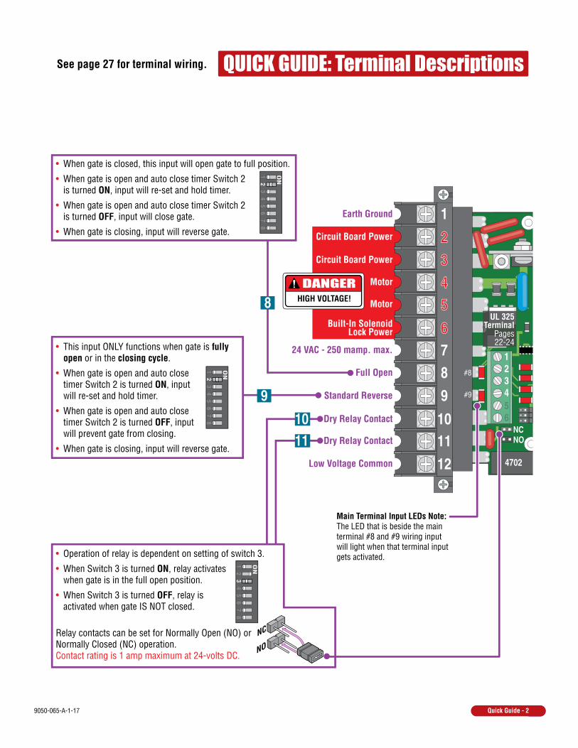
QUICK GUIDE: Terminal DescriptionsSee page 27 for terminal wiring.
DANGERHIGH VOLTAGE!
Low Voltage Common
Dry Relay Contact
Earth Ground
Circuit Board Power
Circuit Board Power
Motor
Motor
Built-In SolenoidLock Power
Full Open
Dry Relay Contact
Standard Reverse
• When gate is closed, this input will open gate to full position.
• When gate is open and auto close timer Switch 2 is turned ON, input will re-set and hold timer.
• When gate is open and auto close timer Switch 2 is turned OFF, input will close gate.
• When gate is closing, input will reverse gate.
• When gate is open and auto close timer Switch 2 is turned ON, input will re-set and hold timer.
• When gate is open and auto close timer Switch 2 is turned OFF, input will prevent gate from closing.
• When gate is closing, input will reverse gate.
• This input ONLY functions when gate is fully open or in the closing cycle.
• Operation of relay is dependent on setting of switch 3.
• When Switch 3 is turned ON, relay activates when gate is in the full open position.
• When Switch 3 is turned OFF, relay is activated when gate IS NOT closed.
Relay contacts can be set for Normally Open (NO) or Normally Closed (NC) operation. Contact rating is 1 amp maximum at 24-volts DC.
8
121110
98766
55443322
1
9
1011
24 VAC - 250 mamp. max.
UL 325Terminal
Pages22-24
NC
NO
ON
12
34
56
78
ON
12
34
56
78
ON
12
34
56
78
Main Terminal Input LEDs Note: The LED that is beside the main terminal #8 and #9 wiring input will light when that terminal input gets activated.
#8
#9
9050-065-A-1-174
11.5” 12”
14.75”
24”
Gate
Fra
me
1” Minimum
4” Minimum
WARNING
MOVING GATE CAN CAUSE
Operate gate only when gate area is in sightand free of people and obstructions.
Do not allow children to play in gate areaor operate gate.
Do not stand in gate path or walk throughpath while gate is moving.
Read owner’s manual and safety instructions.
SERIOUS INJURY OR DEATH
CLASS
CERTIFIED TOCAN/CSA C22.2 NO. 247
CONFORMS TOANSI/UL-325
VEHICULAR GATE OPERATOR
HP
53382
MODEL
SERIAL
VOLTS PHASE
AMPS 60 Hz
MAX GATE LOAD
DoorKing, Inc., Inglewood, CA
10.5”
Chain Height:Idler wheels intop position.
ConcretePad
ConcretePad
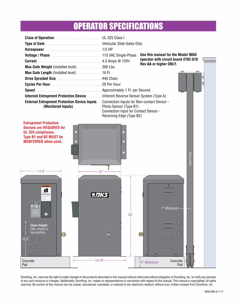
UL 325 Class I Vehicular Slide Gates Only 1/2 HP 115 VAC Single-Phase 4.3 Amps @ 120V 300 Lbs. 16 Ft.#40 Chain 20 Per Hour Approximately 1 Ft. per Second Inherent Reverse Sensor System (Type A)Connection inputs for Non-contact Sensor -Photo Sensor (Type B1)Connection input for Contact Sensor -Reversing Edge (Type B2)
Class of OperationType of GateHorsepowerVoltage / PhaseCurrentMax Gate Weight (Installed level)Max Gate Length (Installed level)Drive Sprocket SizeCycles Per HourSpeedInherent Entrapment Protection DeviceExternal Entrapment Protection Device Inputs (Monitored Inputs)
OPERATOR SPECIFICATIONS
Use this manual for the Model 9050 operator with circuit board 4702-010 Rev AA or higher ONLY.
DoorKing, Inc. reserves the right to make changes in the products described in this manual without notice and without obligation of DoorKing, Inc. to notify any persons of any such revisions or changes. Additionally, DoorKing, Inc. makes no representations or warranties with respect to this manual. This manual is copyrighted, all rights reserved. No portion of this manual may be copied, reproduced, translated, or reduced to any electronic medium without prior written consent from DoorKing, Inc.
Entrapment Protection Devices are REQUIRED for UL 325 compliance.Type B1 and B2 MUST be MONITORED when used.

9050-065-A-1-17 1
SECTION 1 - INSTALLATION 8889
10-131314
15-1616
1.1 Hardware for the Gate1.2 Physical Stops for the Gate1.3 Types of Gates1.4 Operator Mounting Positions1.5 Underground Conduit Requirements1.6 Pad, Post or Ceiling Mount without / with J-Box Setup1.7 Mounting Operator and Chain1.8 Installation of Warning Signs
SECTION 2 - AC POWER TO OPERATOR(S) 171717
2.1 High Voltage Wire Runs2.2 High Voltage Terminal Connection
SECTION 5 - WIRING 26262728
5.1 Main Terminal Description5.2 Control Wiring for Single/Primary Operator5.3 Bi-Parting Gates Wiring - Dual Gate Operators
SECTION 7 - MAINTENANCE AND TROUBLESHOOTING 337.1 Maintenance7.2 Troubleshooting7.3 Accessory ItemsModel 9050 Wiring Diagram
3334-35
3637
SECTION 6 - OPERATING INSTRUCTIONS 296.1 AC Power and Reset Switch6.2 Shutdown Conditions6.3 Manual Gate Operation
2930-3131-32
SECTION 3 - ADJUSTMENTS 183.1 4702 Circuit Board Description and Adjustments3.2 DIP-Switch Settings3.3 Automatic Open / Close Limit Adjustment3.4 Clutch Adjustment3.5 Inherent Reverse Sensor Adjustment
1819202121
SECTION 4 - ENTRAPMENT AND SAFETY PROTECTION 224.1 UL 325 Terminal Description4.2 Entrapment Protection Device Locations4.3 Loop Detector Wiring
2223-24
25
TABLE OF CONTENTS
Quick Guide: DIP-SwitchesQuick Guide: Terminal DescriptionsOperator Specifications
Slide Gate RequirementsSafety Information for Slide Gate OperatorsASTM 2200 Standard for Gate ConstructionImportant Safety InstructionsInstructions regarding intended installation:Important NoticesUL325 Entrapment ProtectionGlossary
Quick Guide-1Quick Guide-2Previous Page
23444567
QUICK GUIDES

9050-065-A-1-172
Slide Gate Requirements The operator is intended for installation only on gates used for vehicles. Pedestrians must be supplied with a separate access opening. The pedestrian access opening shall be designed to promote pedestrian usage. Locate the gate such that persons will not come in contact with the vehicular gate during the entire path of travel of the vehicular gate.(ref. UL 325 56.8.4.b)
All openings of a horizontal slide gate are guarded or screened from the bottom of the gate toa minimum of six (6) feet (1.83 m) above the ground to prevent a 2 1/4 inch (57.2 mm) diameter sphere from passing through the openings anywhere in the gate and in that portion of the adjacent fence that the gate covers in the open position.(ref. ASTM F2200-11a, 6.1.2)
Note: A filler post or barrier may need to be installed in the gap area to reduce the distance to 2 1/4 inches or less.A contact sensor should be installed in this area for safety.(See on nextpage and page 23).
A gap, measured in the horizontal plane parallel to the roadway, between a fixed stationary object
nearest the roadway (such as a gate support post) and the gate frame when the gate is in either the
fully open position or the fully closed position, shall not exceed 2 1/4 inch (57.2 mm).
(ref. ASTM F2200 6.1.4)
Closed Gate
High
Ris
k of
Ent
rapm
ent A
rea
High Risk of Entrapment Area X X X X X X X X X X X X X X X X X X X X X X X X X X X X X X X X X X X X X X X X X X X X X X X X X X X X
X X X X X X X X X X X X X X X X X X X X X X X X X X X X X X X X X X X X X X X X X X X X X X X X X
X X X
Adjacent fence that covers open gate position.
Gate
Sup
port
Post
Gate
Fra
me
A
Gates shall be designed, constructed and installed to not fall over more than 45
degrees from the vertical plane, when a gate is detatched from the supporting hardware. Gu
ide
Rolle
rs
Fall Over Bracket
2 1/
4” m
axim
um g
ap a
rea
Illustrations not to scale.
Screened Wire Mesh Less than 2 1/4”
DoorKing recommends installing screened wire mesh on the ENTIRE gate AND and on that portion of the adjacent fence that the gate covers in the open position. (See above).

9050-065-A-1-17 3
ReverseLoop
AutomaticExit Loop
Minimizes the potential of the gate closing when a vehicle is present. Number and placement of loops is dependent on the application.
ReverseLoop
Minimizes the potential of the gate closing when a vehicle is present. Number and placement of loops is dependent on the application.
(Optional) will provide an open command to the gate operator(s) when a vehicle is exiting the property.
Warning Sign
Moving Gate Can CauseSerious Injury or DeathKEEP CLEAR! Gate may move at any timewithout prior warning.Do not let children operate the gate or playin the gate area.This entrance is for vehicles only.Pedestrians must use separate entrance.
Moving Gate Can CauseSerious Injury or DeathKEEP CLEAR! Gate may move at any timewithout prior warning.Do not let children operate the gate or playin the gate area.This entrance is for vehicles only.Pedestrians must use separate entrance.
11
A
B
C
Closed Gate
Secure Side of Gate
Non-Secure Side of Gate
2
Safety Information for Slide Gate Operators
Physical Stop
Positive stops shall be required to limit travel to the designed fully open and fully closed positions. These stops shall be installed either at the top of the gate, or at the bottom of the gate where such stops shall horizontally or vertically project no more than is required to perform their intended function.
Physical Stops
Permanently mounted and easily visible from either side of the gate.
Warning Signs
Non-Contact Sensors (Photo Sensors)
1
2
Minimizes the potential of the gate closing on vehicular or other traffic that loops cannot sense. It can be installed on the secure OR non-secure side of gate.
Helps minimize the potential of entrapment during the back travel of the gate.
Entrapment protection devices are required to reduce the risk of injury. Install sensors where the risk of entrapment or obstruction exists while gate is moving. Individual requirements will vary. See pages 22-25 for more information on typical layout locations and setup.
Contact Sensor (Reversing Edges)A
Minimizes the potential of the gate closing on vehicular or other traffic that loops cannot sense.
Installed on the fence to help minimize the potential of entrapment between the gate and fence. A filler post or barrier MAY need to be installed between fence and gate.
B
C
Helps minimize the potential of entrapment during the back travel of the gate.
Guide RollersSee previous page for more information.
SeparatePedestrian
WalkwayLocated so pedestrians cannot come in contact with the vehicular gate.
High
Ris
k of
Ent
rapm
ent A
rea
X X
X
X X
X X
X X
X X
X
ScreenedWire MeshMay be necessary on part of fence AND entire gate. See previous page for more information.
Fenc
eFe
nce
Illustration not to scale.
External entrapment protection devices are REQUIRED for operator to function. see page 22

9050-065-A-1-174
Instructions regarding intended installation:
Vehicular gates should be constructed and installed in accordance with ASTM F2200; Standard Specification for Automated Vehicular Gate Construction. For a copy of this standard, contact ASTM directly at 610-832-9585; [email protected]; or www.astm.org.
Important Safety InstructionsWARNING - To reduce the risk of injury or death:1. READ AND FOLLOW ALL INSTRUCTIONS.2. Never let children operate or play with gate controls. Keep the remote control away from children.3. Always keep people and objects away from gate. NO ONE SHOULD CROSS THE PATH OF THE MOVING GATE.4. Test the operator monthly. The gate MUST reverse on contact with a rigid object or stop or reverse when an object activates the non-contact sensors. After adjusting the force or the limit of travel, retest the gate operator. Failure to adjust and retest the gate operator properly can increase the risk of injury or death.5. Use the emergency release only when the gate is not moving.6. KEEP GATES PROPERLY MAINTAINED. Read the owner's manual. Have a qualified service person make repairs to gate hardware.7. The entrance is for vehicles only. Pedestrians must use separate entrance.8. SAVE THESE INSTRUCTIONS!
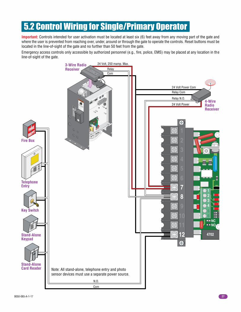
• Install the gate operator only if: 1. The operator is appropriate for the construction of the gate and the usage class of the gate. 2. All openings of a horizontal slide gate are guarded or screened from the bottom of the gate to a minimum of 6 feet (1.83 m) above the ground to prevent a 2 ¼ inch (57.2 mm) diameter sphere from passing through the openings anywhere in the gate, and in that portion of the adjacent fence that the gate covers in the open position. 3. All exposed pinch points are eliminated or guarded. 4. Guarding is supplied for exposed rollers. • The operator is intended for installation only on gates used for vehicles. Pedestrians must be supplied with a separate access opening. The pedestrian access opening shall be designed to promote pedestrian usage. Locate the gate such that persons will not come in contact with the vehicular gate during the entire path of travel of the vehicular gate. • The gate must be installed in a location so that enough clearance is supplied between the gate and adjacent structures when opening and closing to reduce the risk of entrapment. Swinging gates should not open into public access areas.• The gate must be properly installed and work freely in both directions prior to the installation of the gate operator. Do not over-tighten the operator clutch, pressure relief valve or reduce reversing sensitivity to compensate for a damaged gate.• For gate operators utilizing Type D protection: 1. The gate operator controls must be placed so that the user has full view of the gate area when the gate is moving. 2. A warning placard shall be placed adjacent to the controls. 3. An automatic closing device (such as a timer, loop sensor, or similar device) shall not be employed. 4. No other activation device shall be connected.• Controls intended for user activation must be located at least six feet (6’) away from any moving part of the gate and where the user is prevented from reaching over, under, around or through the gate to operate the controls. Outdoor or easily accessible controls should have a security feature to prevent unauthorized use.• The Stop and/or Reset button must be located in the line-of-sight of the gate. Activation of the reset control shall not cause the operator to start.• A minimum of two (2) WARNING SIGNS shall be installed, one on each side of the gate where easily visible.• For gate operators utilizing a non-contact sensor: 1. See the instructions on the placement of non-contact sensors for each type of application. 2. Care shall be exercised to reduce the risk of nuisance tripping, such as when a vehicle trips the sensor while the gate is still moving in the opening direction.
3. One or more non-contact sensors shall be located where the risk of entrapment or obstruction exist, such as the perimeter reachable by a moving gate or barrier.• For gate operators utilizing contact sensors: 1. One or more contact sensors shall be located where the risk of entrapment or obstruction exist, such as at the leading edge, trailing edge, and post mounted both inside and outside of a vehicular horizontal slide gate. 2. One or more contact sensors shall be located at the bottom edge of a vehicular vertical lift gate. 3. One or more contact sensors shall be located at the pinch point of a vehicular vertical pivot gate. 4. A hardwired contact sensor shall be located and its wiring arranged so that the communication between the sensor and the gate operator is not subjected to mechanical damage. 5. A wireless contact sensor such as one that transmits radio frequency (RF) signals to the gate operator for entrapment protection functions shall be located where the transmission of the signals are not obstructed or impeded by building structures, natural landscaping or similar obstructions. A wireless contact sensor shall function under the intended end-use conditions. 6. One or more contact sensors shall be located at the bottom edge of a vertical barrier (arm).
ASTM F2200 Standard for Gate Construction
9050-065-A-1-17 5
Vehicular gate operator products provide convenience and security. However, gate operators must use high levels of force to move gates and most people underestimate the power of these systems and do not realize the potential hazards associated with an incorrectly designed or installed system.These hazards may include:
• Pinch points
• Entrapment areas
• Reach through hazards
• Absence of entrapment protection devices
• Improperly located access controls
• Absence of vehicle protection devices
• Absence of controlled pedestrian access
In addition to these potential hazards, automated vehicular gate systems must be installed in accordance with the UL 325 Safety Standard and the ASTM F2200 Construction Standard. Most people are unaware of, or are not familiar with, these standards. If an automated vehicular gate system is not properly designed, installed, used and maintained, serious injuries or death can result. Be sure that the installer has instructed you on the proper operation of the gate and gate operator system.Be sure that the installer has trained you about the basic functions of the required reversing systems associated with your gate operating system and how to test them. These include reversing loops, inherent reversing system, electric edges, photoelectric cells, or other external devices.
• This Owner’s Manual is your property. Keep it in a safe place for future reference.
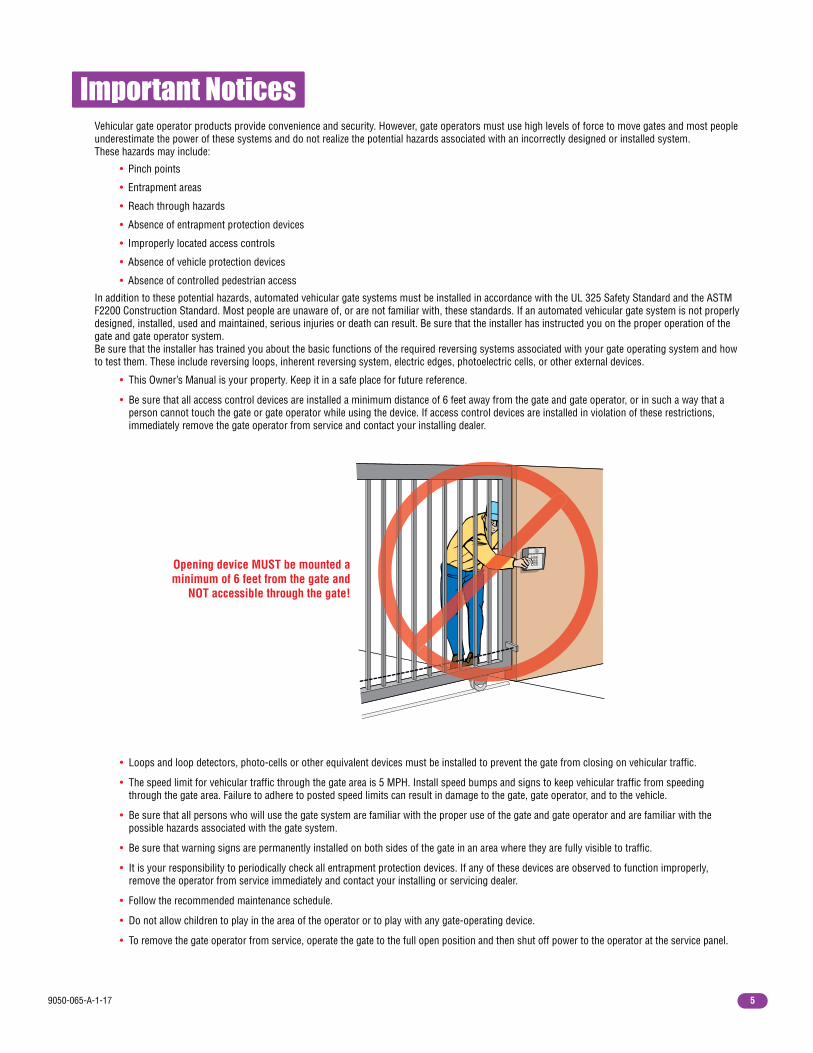
• Be sure that all access control devices are installed a minimum distance of 6 feet away from the gate and gate operator, or in such a way that a person cannot touch the gate or gate operator while using the device. If access control devices are installed in violation of these restrictions, immediately remove the gate operator from service and contact your installing dealer.
Important Notices
• Loops and loop detectors, photo-cells or other equivalent devices must be installed to prevent the gate from closing on vehicular traffic.
• The speed limit for vehicular traffic through the gate area is 5 MPH. Install speed bumps and signs to keep vehicular traffic from speeding through the gate area. Failure to adhere to posted speed limits can result in damage to the gate, gate operator, and to the vehicle.
• Be sure that all persons who will use the gate system are familiar with the proper use of the gate and gate operator and are familiar with the possible hazards associated with the gate system.
• Be sure that warning signs are permanently installed on both sides of the gate in an area where they are fully visible to traffic.
• It is your responsibility to periodically check all entrapment protection devices. If any of these devices are observed to function improperly, remove the operator from service immediately and contact your installing or servicing dealer.
• Follow the recommended maintenance schedule.
• Do not allow children to play in the area of the operator or to play with any gate-operating device.
• To remove the gate operator from service, operate the gate to the full open position and then shut off power to the operator at the service panel.
Opening device MUST be mounted a minimum of 6 feet from the gate and
NOT accessible through the gate!

9050-065-A-1-176
UL 325 Entrapment Protection
Class I - ResidentialVehicular Gate Operator
Entrapment Protection Types
Class II - Commercial/General AccessVehicular Gate Operator
Class III - Industrial/Limited AccessVehicular Gate Operator
Class IV -Restricted AccessVehicular Gate Operator
A vehicular gate operator (or system) intended for use in garages or parking areas associated with a residence of one-to four single families.
A vehicular gate operator (or system) intended for use in a commercial location or building such as a multi-family housing unit (five or more single family units), hotel, garages, retail store, or other buildings accessible by or servicing the general public.
A vehicular gate operator (or system) intended for use in an industrial location or building such as a factory or loading dock area or other locations not accessible by or intended to service the general public.
A vehicular gate operator (or system) intended for use in a guarded industrial location or building such as an airport security area or other restricted access locations not servicing the general public, in which unauthorized access is prevented via supervision by security personnel.
Gate Operator Category
UL 325 Classifications
Type A - Inherent entrapment protection system.
Type B1 - Non-contact sensor (photoelectric sensor or the equivalent).
Type B2 - Contact sensor (edge device or equivalent).
Type C - Inherent force limiting, inherent adjustable clutch or inherent pressure relief device.
Type D - Actuating device requiring constant pressure to maintain opening or closing motion of the gate.
* B1 and B2 means of entrapment protection must be MONITORED.
Vertical Barrier Note: Barrier gate operators (arm) that is not intended to move toward a rigid object closer than 16 inches (406 mm) are not required to be provided with a means of entrapment protection.
STATE PRISON
Horizontal Slide, Vertical Lift, Vertical Pivot Swing, Vertical Barrier (Arm)
A, B1*, B2* or D A, B1*, B2*, C or D
Effective January 12, 2016
AuthorizedPersonnel ONLY

9050-065-A-1-17 7
Glossary GATE - A moving barrier such as a swinging, sliding, raising, lowering, or the like, barrier, that is a stand-alone passage barrier or is that portion of a wall or fence system that controls entrance and/or egress by persons or vehicles and completes the perimeter of a defined area.
RESIDENTIAL VEHICULAR GATE OPERATOR – CLASS I - A vehicular gate operator (or system) intended for use in a home of one-to four single family dwelling, or garage or parking area associated therewith.
COMMERCIAL / GENERAL ACCESS VEHICULAR GATE OPERATOR - CLASS II - A vehicular gate operator (or system) intended for use in a commercial location or building such as a multi-family housing unit (five or more single family units), hotels, garages, retail store, or other building servicing the general public.
INDUSTRIAL / LIMITED ACCESS VEHICULAR GATE OPERATOR - CLASS III - A vehicular gate operator (or system) intended for use in an industrial location or building such as a factory or loading dock area or other locations not intended to service the general public.
RESTRICTED ACCESS VEHICULAR GATE OPERATOR - CLASS IV - A vehicular gate operator (or system) intended for use in a guarded industrial location or building such as an airport security area or other restricted access locations not servicing the general public, in which unauthorized access is prevented via supervision by security personnel.
VEHICULAR BARRIER (ARM) OPERATOR (OR SYSTEM) - An operator (or system) that controls a cantilever type device (or system), consisting of a mechanical arm or barrier that moves in a vertical arc, intended for vehicular traffic flow at entrances or exits to areas such as parking garages, lots or toll areas.
VEHICULAR HORIZONTAL SLIDE-GATE OPERATOR (OR SYSTEM) - A vehicular gate operator (or system) that controls a gate which slides in a horizontal direction that is intended for use for vehicular entrance and exit to a drive, parking lot, or the like.
VEHICULAR SWING-GATE OPERATOR (OR SYSTEM) - A vehicular gate operator (or system) that controls a gate which moves in an arc in a horizontal plane that is intended for use for vehicular entrance and exit to a drive, parking lot, or the like.
SYSTEM - In the context of these requirements, a system refers to a group of interacting devices intended to perform a common function.
WIRED CONTROL - A control implemented in a form of fixed physical interconnections between the control, the associated devices, and an operator to perform predetermined functions in response to input signals.
WIRELESS CONTROL - A control implemented in means other than fixed physical interconnections (such as radio waves or infrared beams) between the control, the associated devices, and an operator to perform predetermined functions in response to input signals.
INHERENT ENTRAPMENT PROTECTION SYSTEM - A system, examples being a motor current or speed sensing system, which provides protection against entrapment upon sensing an object and is incorporated as a permanent and integral part of the operator.
EXTERNAL ENTRAPMENT PROTECTION DEVICE - A device, examples being an edge sensor, a photoelectric sensor, or similar entrapment protection device, which provides protection against entrapment when activated and is not incorporated as a permanent part of an operator.
ENTRAPMENT - The condition when an object is caught or held in a position that increases the risk of injury.

9050-065-A-1-178
Gate End Retainer
End Post
SECTION 1 - INSTALLATION
1.2 Physical Stops for the Gate
1.1 Hardware for the Gate Good hardware is essential for proper operation of a sliding gate. DoorKing has a full line of gate hardware products that will ensure safe, reliable and long lasting gate operation. The gate must be properly installed and roll smoothly in both directions.
Rubber bumper faces toward operator. it will make contact with the operator housing
during the initial automatic “Multiple gate cycling” to set the open and close gate position.
The 9050 automatic open/close gate limits must have a physical stop on the open and close positions of the gate. This can be the use of end posts with gate end retainers or chain stops, depending on the mounting position of the operator. Chain stops DO NOT meet the ASTM F2200 requirements.
Gate End Retainer - Helps stabilize the end of the gate in the open or closed position. Recommended for all slide gate applications.
Endless Idler Assembly with Protective Cover - Helps to minimize a pinch point for a 180° chain return.
Guide Rollers with Protective Covers - Helps to minimize a pinch point on the gate.
Roller Bearing V-Wheels with Protective Cover - Helps to minimize a pinch point on the gate’s wheel and V-rail.
Chain Stops
Gate
Prior to beginning the installation of the slide gate operator, we suggest that you become familiar with the instructions, illustrations, and wiring guide-lines in this manual. This will help insure that your installation is performed in an efficient and professional manner compliant with UL 325 safety and ASTM F2200 construction standards. The proper installation of the vehicular slide gate operator is an extremely important and integral part of the overall access control system. Check all local building ordinances and building codes prior to installing this operator. Be sure your installation is in compliance with local codes.

9050-065-A-1-17 9
1.3 Typical Gate TypesThe Model 9050 operator is designed to be installed on these gate types. See the next 4 pages for specific operator mounting positions. Individual installations and physical stops can vary.
V-Rail V-Wheel Ornamental
Cantilever
• 300 lb max. weight per gate.
• Single Operator - 16 ft max. gate length.
• Dual Operators - 32 ft max. total gate length.
WARNING
MOVING GATE CAN CAUSE
Operate gate only when gate area is in sight
and free of people and obstructions.
Do not allow children to play in gate area
or operate gate.Do not stand in gate path or walk through
path while gate is moving.
Read owner’s manual and safety instructions.
SERIOUS INJURY OR DEATH
CLASS
CERTIFIED TO
CAN/CSA C22.2 NO. 247
CONFORMS TO
ANSI/UL-325
VEHICULAR GATE OPERATORHP
53382
MODELSERIALVOLTS
PHASE
AMPS
60 Hz
MAX GATE LOADDoorKing, Inc., Inglewood, CA
Front position with post mount shown.
Chain stops used as physical stops for gate.
Front position with concrete pad shown.
Gate end retainers on end posts used as physical stops for gate.
WARNING
MOVING GATE CAN CAUSE
Operate gate only when gate area is in sight
and free of people and obstructions.
Do not allow children to play in gate area
or operate gate.Do not stand in gate path or walk through
path while gate is moving.
Read owner’s manual and safety instructions.
SERIOUS INJURY OR DEATH
CLASS
CERTIFIED TO
CAN/CSA C22.2 NO. 247
CONFORMS TO
ANSI/UL-325
VEHICULAR GATE OPERATORHP
53382
MODELSERIALVOLTS
PHASE
AMPS
60 Hz
MAX GATE LOADDoorKing, Inc., Inglewood, CA

9050-065-A-1-1710
1.4 Operator Mounting Positions
• Operator’s chain idler wheels are factory set for the front position. • Remove only the top chain knockouts from each side of the operator.• Chain stops or gate end retainer can be used as the physical stop for the gate (Chain stops are shown).
Front Position with Concrete PadStandard method of installation.
Front Position with Post MountRaises operator and allows different chain heights.
Chain Stop
Chain Idler Wheels
Chain IdlerWheels
ChainStop
Gate End Retainer
Gate End Retainer
Gate End Retainer
Top View
Top View
The Model 9050 operator is designed to be installed in the front, rear, center or ceiling mounting positions shown on this page and the next 3 pages. V-wheel V-rail ornamental gates are shown as examples but other gate types on the previous page can use the same mounting setups. Once the mounting position has been determined, the chain idler wheels may need to be adjusted BEFORE the operator is mounted. Physical stops MUST be used in the open AND close positions for ANY gate installation (Chain stops, end posts with gate end retainers or a wall that the gate comes in contact with).
Chain Setup
Chain Setup
A filler post or barrier may need to be installed between the gate and wall area (See page 2 for more information).
A filler post or barrier may need to be installed between the gate and wall area (See page 2 for more information).
Additional hardware required. Post base plate (P/N 2600-418) 4 x 4 steel posts not available from DoorKing.Base plate stop brackets (P/N 2600-970) bolts on post base plate when using chain stops.
• Set operator chain idler wheels in the bottom position.• DO NOT remove chain knockouts.• Chain stops with base plate stop brackets or gate end retainer can be used as the physical stop for the gate (Both are shown, only one type is needed).
Base PlateStop Bracket
9050-065-A-1-17 11
See page 16 for more information about endless idlers.
EndlessIdler
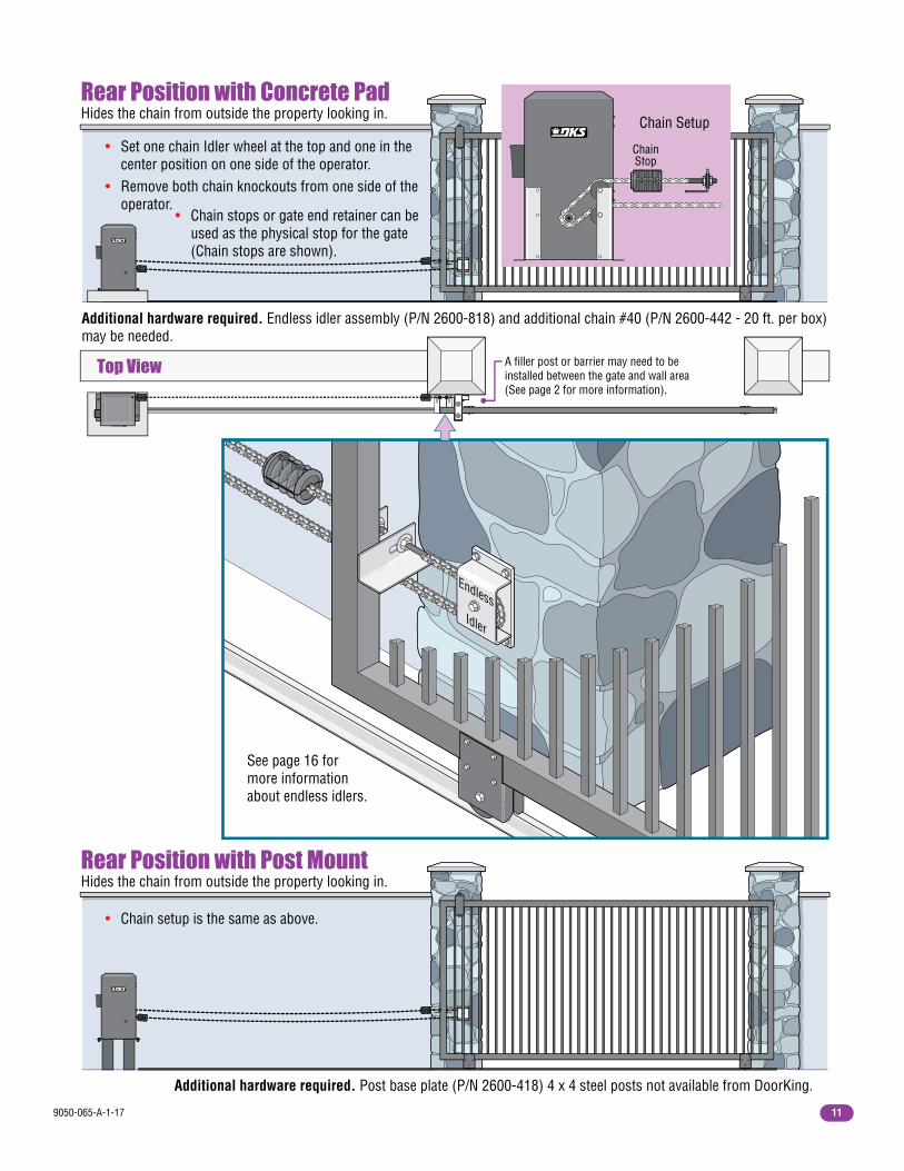
• Set one chain Idler wheel at the top and one in the center position on one side of the operator. • Remove both chain knockouts from one side of the operator.
• Chain stops or gate end retainer can be used as the physical stop for the gate (Chain stops are shown).
Additional hardware required. Endless idler assembly (P/N 2600-818) and additional chain #40 (P/N 2600-442 - 20 ft. per box) may be needed.
Additional hardware required. Post base plate (P/N 2600-418) 4 x 4 steel posts not available from DoorKing.
Rear Position with Concrete PadHides the chain from outside the property looking in.
• Chain setup is the same as above.
Rear Position with Post MountHides the chain from outside the property looking in.
Chain Idler Wheels
ChainStop
Chain Setup
Top View A filler post or barrier may need to be installed between the gate and wall area (See page 2 for more information).
9050-065-A-1-1712
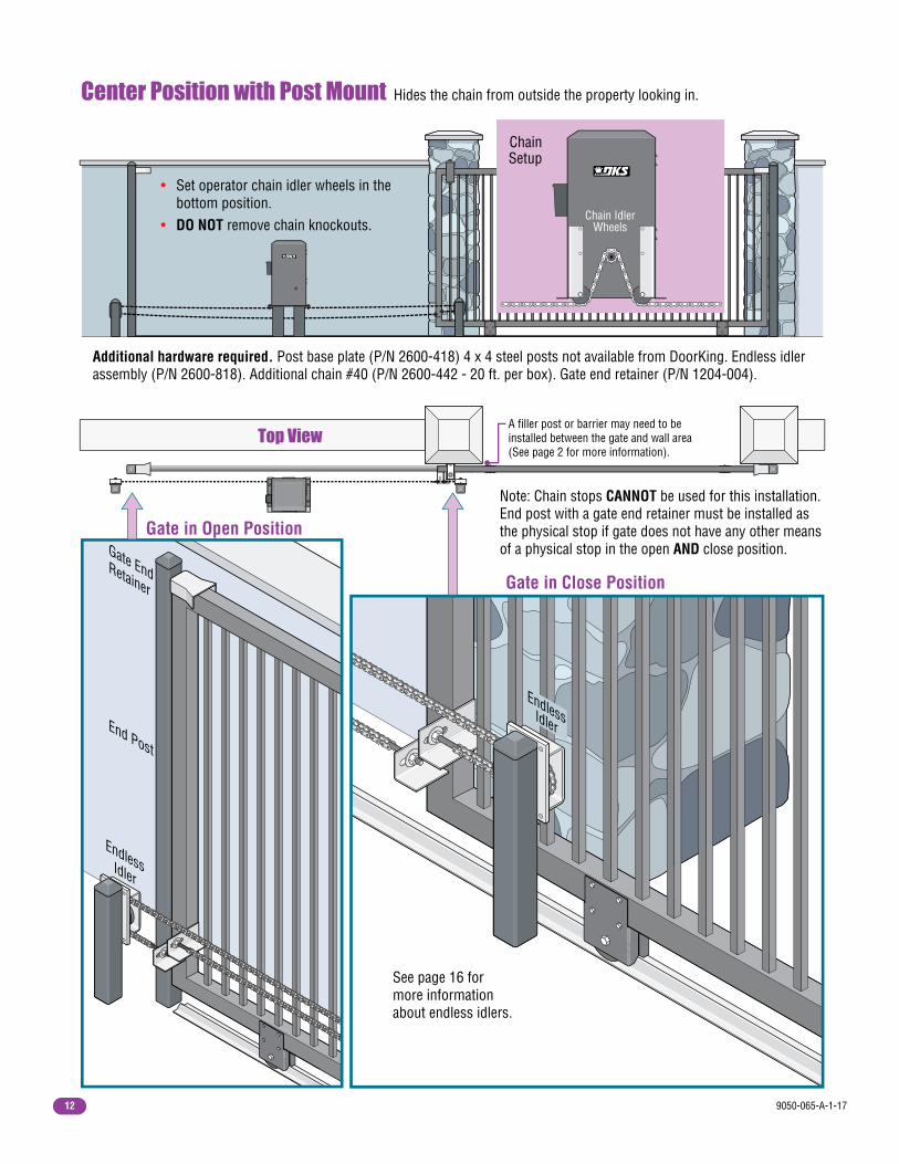
Note: Chain stops CANNOT be used for this installation. End post with a gate end retainer must be installed as the physical stop if gate does not have any other means of a physical stop in the open AND close position.
Gate in Close Position
EndlessIdler
Additional hardware required. Post base plate (P/N 2600-418) 4 x 4 steel posts not available from DoorKing. Endless idler assembly (P/N 2600-818). Additional chain #40 (P/N 2600-442 - 20 ft. per box). Gate end retainer (P/N 1204-004).
Center Position with Post Mount Hides the chain from outside the property looking in.
• Set operator chain idler wheels in the bottom position. • DO NOT remove chain knockouts.
Chain Idler Wheels
Gate End Retainer
End Post
Endless Idler
Gate in Open Position
Top View
ChainSetup
See page 16 for more information about endless idlers.
A filler post or barrier may need to be installed between the gate and wall area (See page 2 for more information).

9050-065-A-1-17 13
1.5 Underground Conduit Requirements
Sweeps
ConcretePad
PrimaryOperatorPosition
SecondaryOperatorPosition
• Operator’s setup is the same as the front position or rear position with concrete pad shown on page 10 and 11. (Front ceiling mount shown here).• Junction box connection is used for the ceiling mount installation (See page 14).
Front or Rear Position Ceiling MountCan be mounted on the ceiling to conserve floor space.
Chain Stop
Ceiling
Chain Idler Wheels
Note: There are NO fluids in the operator that can leak out.
Operator Bottom
Top View
Chain Setup
DoorKing’s Primary/Secondary Interconnection Cable (Dual Operator Application Only)(Secondary Power and Communication wires)
Loop Lead-In Wires (Low Voltage wire insulation)
AC Input Power (High Voltage wire insulation)AC Input Power (High Voltage wire insulation)
3/4 Inch Conduit Recommended
A filler post or barrier may need to be installed between the gate and wall area (See page 2 for more information).
ElbowNO
SweepYES
• The conduit requirements are for a typical slide gate operator installation (the secondary operator is shown for those applications where a secondary operator may be used). The conduit requirements for your application may vary from this depending on your specific needs.• Use only sweeps for conduit bends. Do not use 90° elbows as this will make wire pulls very difficult and can cause damage to wire insulation. DoorKing recommends using 3/4-inch conduit.• Installation of External Entrapment Protection Devices are REQUIRED (photo sensors and/or reversing edges).• Be sure that all conduits are installed in accordance with local codes.• Never run low voltage rated wire insulation in the same conduit as high voltage rated wire insulation.
External Safety Devices, Controls and P.A.M.S. Wires (Low Voltage wire insulation)

9050-065-A-1-1714
4” 11” Solenoid
Lock
Conduit Area
2.5”
Electronic Box
1.6 Pad, Post or Ceiling Mount without/with J-Box Setup
Post Mount with Conduit
Pad Mount with Conduit
15” Min.
21” Min. Concrete Pad
Center
Concrete Pad
Concrete Foundation Conduit
Conc
rete
Fou
ndat
ion
1” minimum from operator housing to gate.
4” min. above ground.
4” min. above ground.
1” minimum from operator housing to gate.
Underground depth of the concrete pad is determined by soil conditions and local building codes. Reinforced
concrete recommended.
Underground depth of the concrete foundation is
determined by soil conditions and local
building codes. Reinforced concrete recommended.
Concrete pad MUST be level.
Base Plate MUST be level.
Operator MUST be level.
Conduit area
inside post.
Conduit area
inside post.
Pad, Post or Ceiling Mount Connected with Junction BoxesAll wire connections
can be made on either side of the
operator housing after it has been installed.
Never run high voltage and low voltage in the same conduit.
Conduit Knock-Out Sizes
Low Volt
High Volt
1/2 1/2
3/4 1/2
Fail-Secure Key Lock
1/2
3/4 1/2
Note: Weld the posts to the base plate and mount assembly into concrete BEFORE attaching the operator. Conduit runs up through 4 x 4 steel posts.
Note: Operator must be mounted 1” min. away from gate.
Low Volt
High Volt
WARNING
MOVING GATE CAN CAUSE
Operate gate only when gate area is in sight and free of people and obstructions. Do not allow children to play in gate area or operate gate. Do not stand in gate path or walk through path while gate is moving. Read owner’s manual and safety instructions.
SERIOUS INJURY OR DEATH
CLASS
CERTIFIED TOCAN/CSA C22.2 NO. 247
CONFORMS TOANSI/UL-325
VEHICULAR GATE OPERATOR
HP
53382
MODEL
SERIAL
VOLTS PHASE
AMPS 60 Hz
MAX GATE LOAD
DoorKing, Inc., Inglewood, CA
Conduit Conduit
Base PlateP/N 2600-418
Pad, post or ceiling mount
Conduit
12” Min.
21” Min.
9050-065-A-1-17 15
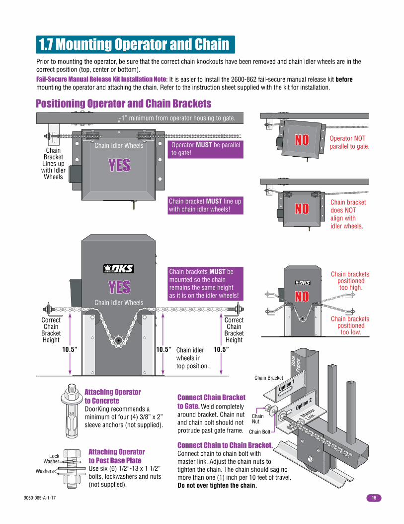
1.7 Mounting Operator and Chain
1” minimum from operator housing to gate.
Prior to mounting the operator, be sure that the correct chain knockouts have been removed and chain idler wheels are in the correct position (top, center or bottom). Fail-Secure Manual Release Kit Installation Note: It is easier to install the 2600-862 fail-secure manual release kit before mounting the operator and attaching the chain. Refer to the instruction sheet supplied with the kit for installation.
Operator MUST be parallel to gate!
DoorKing recommends a minimum of four (4) 3/8” x 2” sleeve anchors (not supplied).
Use six (6) 1/2”-13 x 1 1/2” bolts, lockwashers and nuts (not supplied).
Operator NOT parallel to gate.
Chain bracket does NOT align with idler wheels.
Chain bracket MUST line up with chain idler wheels!
Chain brackets MUST be mounted so the chain remains the same height as it is on the idler wheels!
YES YES
Positioning Operator and Chain Brackets
Attaching Operatorto Concrete
Attaching Operatorto Post Base Plate
Chain Bracket Lines up with Idler Wheels
Correct Chain
Bracket Height
Correct Chain
Bracket Height
Chain brackets positionedtoo high.
Chain brackets positionedtoo low.
LockWasher
Washers
Chain Idler Wheels
Chain Idler Wheels
3/8
YESYESNONO
NONO
NONO
Connect Chain Bracketto Gate. Weld completely around bracket. Chain nut and chain bolt should not protrude past gate frame.
Connect chain to chain bolt with master link. Adjust the chain nuts to tighten the chain. The chain should sag no more than one (1) inch per 10 feet of travel. Do not over tighten the chain.
Connect Chain to Chain Bracket.
ChainNut
Chain Bolt
Chain Bracket
Option 2
Master
Link
Option 1
Gate
Fram
e
10.5”10.5”10.5” Chain idler wheels in top position.

9050-065-A-1-1716
Endless Idler Assembly (On Select Installations)
1.8 Installation of Warning SignsThis DoorKing Slide Gate Operator is shipped with two warning signs. The purpose of the warning sign is to alert uninformed persons, and to remind persons familiar with the gate system, that a possible hazard exists so that appropriate action can be taken to avoid the hazard or to reduce exposure to the hazard. See page 3 for suggested mounting positions of signs.
• Permanently install the supplied warning signs in locations so that the signs are visible by persons on both sides of the gate.
• Use appropriate hardware such as wood or sheet metal screws (not supplied) to install the warning signs.
Lower chain does NOT align with upper chain.Note: Be sure that the chain is aligned and parallel to the gate. Installing the chain in any other manner will cause excessive noise, chain idler wheel wear and chain stretching.
Lower chain MUST align with upper chain!
NO
NO
NO
Gate Rail
Operator Idler Wheel
OperatorIdler Wheel
Lower chain mounted Too High.
Lower chain mountedToo Low.
DoorKing offers an endless idler assembly with a protective cover designed for the Model 9050 installations (P/N 2600-818). Make sure the endless idler assembly is securely fastened to the wall or post (Depending on which type of installation will be used). Extreme force will be exerted on this assembly during gate cycling.
Lower chain MUST be 1 inch lower than the endless idler’s 180° chain return.
Center and Rear Mount Positions (Top View)
Center Mount Position (Side View)
Gate Rail
ChainBracket
Chain Brackets
EndlessIdler
EndlessIdler
Upper Chain
Lower ChainChainBracket
ChainReturn
1”
YES
YES
Upper and lower chain MUST be the same height as they are on the operator idler wheels.
Gate Rail
ChainBracket
EndlessIdler
Upper Chain
Lower Chain
ChainBracket
ChainReturn
Operator Idler Wheels
NO
NO
Upper chain mounted Too High.
Upper chain mountedToo Low.
Rear Mount Position (Side View) YES
9050-065-A-1-17 17
2.1 High Voltage Wire Runs
2.2 High Voltage Terminal Connection
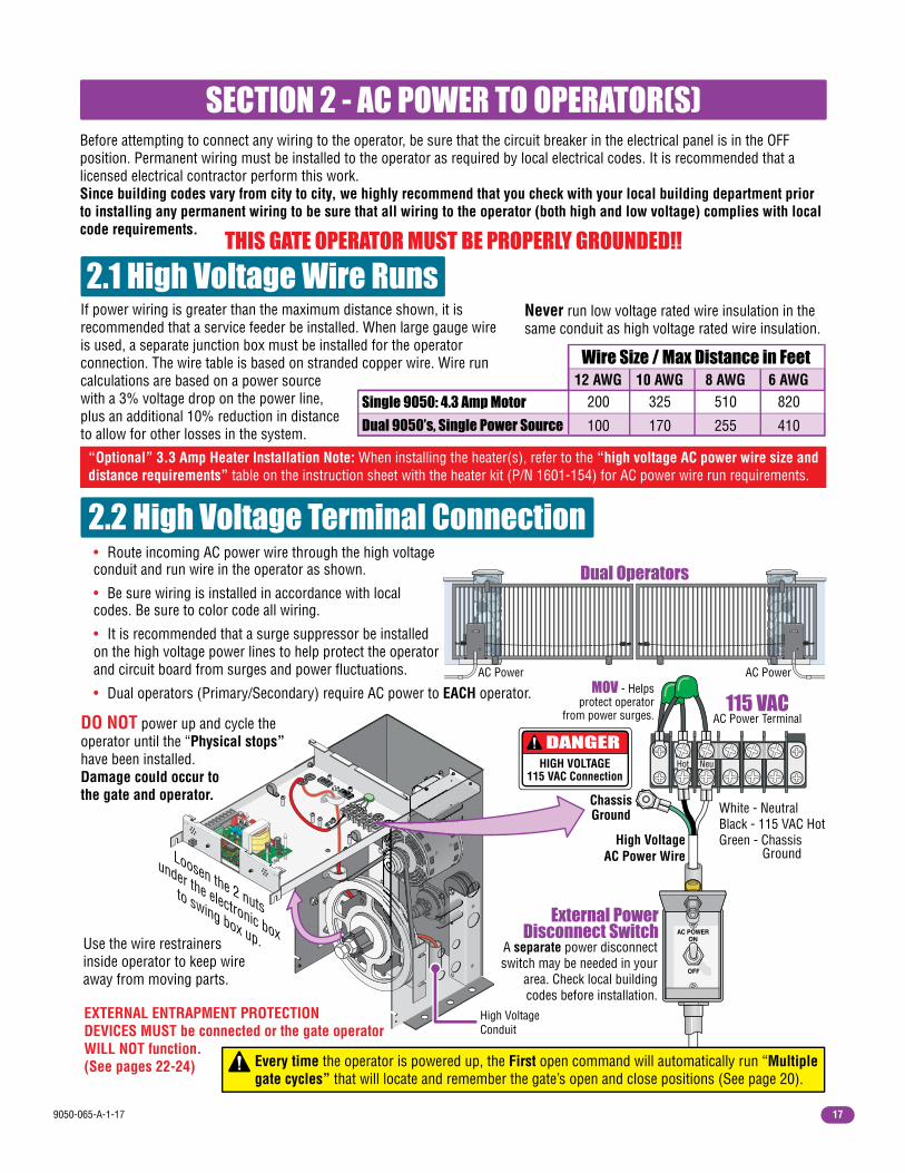
If power wiring is greater than the maximum distance shown, it is recommended that a service feeder be installed. When large gauge wire is used, a separate junction box must be installed for the operator connection. The wire table is based on stranded copper wire. Wire run calculations are based on a power source with a 3% voltage drop on the power line, plus an additional 10% reduction in distance to allow for other losses in the system.
Use the wire restrainersinside operator to keep wire away from moving parts.
Wire Size / Max Distance in Feet
200 325 510 82012 AWG 10 AWG 8 AWG 6 AWG
Single 9050: 4.3 Amp Motor
100 170 255 410Dual 9050’s, Single Power Source
ChassisGround
SECTION 2 - AC POWER TO OPERATOR(S)Before attempting to connect any wiring to the operator, be sure that the circuit breaker in the electrical panel is in the OFF position. Permanent wiring must be installed to the operator as required by local electrical codes. It is recommended that a licensed electrical contractor perform this work. Since building codes vary from city to city, we highly recommend that you check with your local building department prior to installing any permanent wiring to be sure that all wiring to the operator (both high and low voltage) complies with local code requirements.
THIS GATE OPERATOR MUST BE PROPERLY GROUNDED!!
DANGERHIGH VOLTAGE
115 VAC Connection
High VoltageConduit
MOV - Helps protect operator
from power surges.
• Route incoming AC power wire through the high voltage conduit and run wire in the operator as shown.
• Be sure wiring is installed in accordance with local codes. Be sure to color code all wiring.
• It is recommended that a surge suppressor be installed on the high voltage power lines to help protect the operator and circuit board from surges and power fluctuations.
• Dual operators (Primary/Secondary) require AC power to EACH operator.AC Power AC Power
Dual Operators
Loosen the 2 nuts
under the electronic box
to swing box up.
DO NOT power up and cycle the operator until the “Physical stops” have been installed.Damage could occur tothe gate and operator.
Never run low voltage rated wire insulation in the same conduit as high voltage rated wire insulation.
“Optional” 3.3 Amp Heater Installation Note: When installing the heater(s), refer to the “high voltage AC power wire size and distance requirements” table on the instruction sheet with the heater kit (P/N 1601-154) for AC power wire run requirements.
A separate power disconnect switch may be needed in your
area. Check local building codes before installation.
115 VACAC Power Terminal
White - NeutralBlack - 115 VAC HotGreen - Chassis Ground
Hot Neu
High VoltageAC Power Wire
External PowerDisconnect Switch AC POWER
ON
OFF
Every time the operator is powered up, the First open command will automatically run “Multiple gate cycles” that will locate and remember the gate’s open and close positions (See page 20).
EXTERNAL ENTRAPMENT PROTECTIONDEVICES MUST be connected or the gate operatorWILL NOT function.(See pages 22-24)

9050-065-A-1-1718
NCNO TIME
DELAY
REVSENS
REVERSE LOOP
EXIT LOOP
4702-010
123456
1 ON
23
4
ON
12
34
56
78
4
L1
121110
9876
5432
1
9410
L1
9410
3.1 4702 Circuit Board Description and Adjustments
SECTION 3 - ADJUSTMENTSThe switch settings and adjustments in this chapter should be made after your installation and wiring to the operator(s) is complete. Whenever any of the programming switches on the circuit board are changed, power must be shut-off, and then turned back on for the new setting to take effect. Every time the operator is powered up, the First open command will automatically run “Multiple gate cycles” that will locate and remember the gate’s open and close positions (See page 20).
Auto-close timer (when turned ON) Switch 2.
Adjust from 1 second (full counter clockwise) to approximately 23 seconds (full clockwise).
Auto-Close Timer
Dry Relay Contact
LEDs Indicates that low voltage power is applied to the circuit board. Input LEDs should be OFF and will only illuminate when the input is activated. Pulse LEDs will blink as the operator is running. They can be either ON or OFF when the operator is stopped.
Adjust reversing sensitivity.Full counter clockwise for minimum sensitivity, full clockwise for maximum sensitivity. See page 21.
LEDs will turn on when the inherent reverse sensor is activated.
Min MaxSensitivity
Inherent Reverse Sensor
UL 325TerminalPage 22
UL 325DIP-Switches
Page 22
Power LED
Pulse LEDs
98Input LEDs
Page 26 O1
UL 325 LEDsPage 22
Magnetic SensorsSee section 3.4 on page 21.
Loop Detector See page 25.Exit Loop Port Reverse Loop Port
Loop Detector See page 25.Single Channel
Single Channel
1 23
See switch setting chart on next page for DIP-Switch options.
DIP-SwitchesTypical setting shown.
Dry relay contacts (terminals 10-11) can be set for Normally Open (NO) or Normally Closed (NC) operationby placing the relay shorting baron the N.O. or N.C. pinsrespectively. DIP-switch 3 mustbe set to control relay.See next page and page 26.
TIMEDELAY
ON
12
34
56
78
ON
12
34
56
78
ON
12
34
56
78
NC
NO
Pulse LEDs will blink as the operator is running. They can be either ON or OFF when the operator is stopped.

9050-065-A-1-17 19
7-OFF7-OFF7-ON7-ON
8-OFF8-ON
8-OFF8-ON
Gate CloseBack-OffPosition
Gate OpenBack-OffPosition
Normal Setting. Gate fully opens. Gate stops short 1” from full open position. Used for a reversing edge device.Gate stops short 2” from full open position. Used for a reversing edge device. Gate stops short 3” from full open position. Used for a reversing edge device.
3.2 DIP-Switch Settings The DIP-switches located on the circuit board are used to program the operator to operate in various modes and to turn on or off various operating features. Whenever a switch setting is changed, power to the operator must be turned OFF and then turned back on for the new setting to take affect. Check and review ALL switch settings prior to applying power to the operator.
Switch 1 Must OPEN the gate upon initial AC power up and open command. If the first open command begins to close the gate, turn AC power off and reverse this switch. Opening direction will vary depending on the chain setup position (See above).
Switch 2 Turns the auto-close timer on or off. Can be adjusted from 1 to 23 seconds to close gate.
Switch 3 This switch determines when the relay on the board will be activated. This relay can be used as a switch for various functions such as illuminating a warning light when the gate is not closed, or turning on a green light when the gate is full open.
Switch 4 This switch determines the operation of the built-in solenoid lock. The OFF setting is the factory setup. Caution: Do not set this switch to ON unless the 2600-862 fail-secure manual release kit has been installed in the operator. Changing this switch to the ON setting without installing the lock kit will damage the operator. See pages 31 and 32 for more information about Fail-Safe vs. Fail-Secure release systems.
Switches 5-6 These work in conjunction with each other and determine if the operator will stop the gate at the full open position, or if the gate should stop 1, 2 or 3 inches short of the full open position. Needed only when using a reversing edge entrapment protection device on the opening edge of the gate with an end post as the physical stop.
Switches 7-8 These work in conjunction with each other and determine if the operator will stop the gate at the full close position, or if the gate should stop 1, 2 or 3 inches short of the full close position. Needed only when using a reversing edge entrapment protection device on the closing edge of the gate with an end post as the physical stop.
Switch Function Setting Description
OFFON
5-OFF5-OFF5-ON5-ON
6-OFF6-ON
6-OFF6-ON
Auto-CloseTimer2
1
Relay OFFON
3
4
5 and 6
7 and 8
Relay is activated when gate is full open.Relay is activated when gate is not closed.
Auto-close timer is OFF. Manual input required to close gate.Auto-close timer is ON. Adjustable from 1-23 seconds to close gate.
OFF
ON
Normal Setting. Fail-Safe (Factory Set). Lock engages only when an attempt is made to manually force the gate open.
Fail-Secure. Lock engages after each cycle. CAUTION: Do not use this setting unless the 2600-862 manual release kit has been installed or damage will occur to operator.
Normal Setting. Gate fully closes. Gate stops short 1” from full close position. Used for a reversing edge device.Gate stops short 2” from full close position. Used for a reversing edge device. Gate stops short 3” from full close position. Used for a reversing edge device.
Changes the direction the operator will open/close the gate depending on the different chain configurations.
Openingdirection
using OFFsetting.
Openingdirectionusing ONsetting.
Mount
FrontOpeningdirectionusing ON
setting.
Openingdirectionusing OFFsetting.
PostMounts
Center orOpenswith
OFFsetting.
MountsRight
All RearOpens
with
ONsetting.
MountsLeft
All Rear
Every time the operator is powered up, the First open command will automatically run “Multiple gate cycles” that will locate and remember the gate’s open and close positions (See next page).
Built-InSolenoid Lock
See Page 31-32
9050-065-A-1-1720
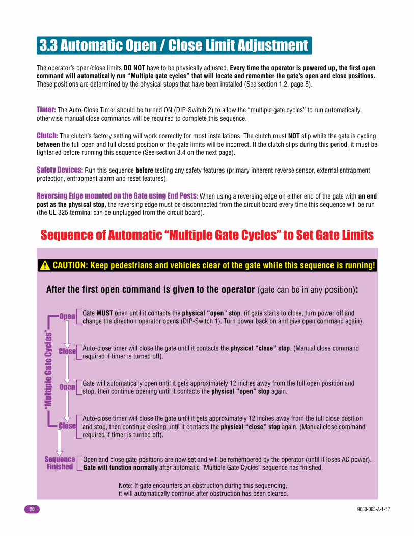
3.3 Automatic Open / Close Limit Adjustment
Gate MUST open until it contacts the physical “open” stop. (if gate starts to close, turn power off and change the direction operator opens (DIP-Switch 1). Turn power back on and give open command again).
Auto-close timer will close the gate until it contacts the physical “close” stop. (Manual close command required if timer is turned off).
Gate will automatically open until it gets approximately 12 inches away from the full open position and stop, then continue opening until it contacts the physical “open” stop again.
Auto-close timer will close the gate until it gets approximately 12 inches away from the full close position and stop, then continue closing until it contacts the physical “close” stop again. (Manual close command required if timer is turned off).
Sequence of Automatic “Multiple Gate Cycles” to Set Gate Limits
Open
Open
Close
Close
Sequence Finished
After the first open command is given to the operator (gate can be in any position):
Open and close gate positions are now set and will be remembered by the operator (until it loses AC power). Gate will function normally after automatic “Multiple Gate Cycles” sequence has finished.
The operator’s open/close limits DO NOT have to be physically adjusted. Every time the operator is powered up, the first open command will automatically run “Multiple gate cycles” that will locate and remember the gate’s open and close positions. These positions are determined by the physical stops that have been installed (See section 1.2, page 8).
Timer: The Auto-Close Timer should be turned ON (DIP-Switch 2) to allow the “multiple gate cycles” to run automatically, otherwise manual close commands will be required to complete this sequence.
Clutch: The clutch’s factory setting will work correctly for most installations. The clutch must NOT slip while the gate is cycling between the full open and full closed position or the gate limits will be incorrect. If the clutch slips during this period, it must be tightened before running this sequence (See section 3.4 on the next page).
Safety Devices: Run this sequence before testing any safety features (primary inherent reverse sensor, external entrapment protection, entrapment alarm and reset features).
Reversing Edge mounted on the Gate using End Posts: When using a reversing edge on either end of the gate with an end post as the physical stop, the reversing edge must be disconnected from the circuit board every time this sequence will be run (the UL 325 terminal can be unplugged from the circuit board).
CAUTION: Keep pedestrians and vehicles clear of the gate while this sequence is running!
Note: If gate encounters an obstruction during this sequencing, it will automatically continue after obstruction has been cleared.
“Mul
tipl
e Ga
te C
ycle
s”

9050-065-A-1-17 21
Give open command to cycle the gate or momentarily jumper terminals 8 and 12 to open gate.
While gate is cycling, slowly rotate reverse sensor clockwise until the gate reverses direction.Rotate reverse sensor back counter-clockwise approximately 1/8 turn.
Cycle the gate a few times to be sure that it cycles completely.
1
2
3
Min MaxSensitivity
ReverseSensitivity
Note: Each operator must be individually adjusted if dual operators have been installed.
3.4 Clutch Adjustment
Test the operator clutch adjustment:CAUTION: Keep pedestrians and vehicles clear of the gate while testing clutch! Place an immobile object along the gate path, allowing the gate to strike it while in the open and close cycles. The clutch must slip and the gate must reverse direction after striking the object. If it does not, readjust the clutch. Repeat this test until the correct clutch adjustment has been achieved. The operator will assume a soft shutdown after striking and reversing the gate which will require a key switch command to cycle operator again.
123
4
In addition to the inherent reverse sensor, this operator is equipped with a mechanical slip clutch (UL 325 Type C) to further reduce the possibility of injury should an entrapment occur. DO NOT over tighten the clutch to compensate for a gate that is damaged, poorly constructed or too heavy. Over tightening the clutch would create a hazard which could result in serious injury or death to persons who may become entrapped.
Hex Bolt
MagneticSpring Assembly
To adjust clutch:
Hex nut is connected to black plastic magnet holder.
Important Note: 2 magnetic sensors located on the bottom of the circuit board sense when the magnetic spring assembly is slipping during operation. Keep all high voltage wires away from the 2 sensors to avoid any electrical interference between the sensors and magnets.
Note: After power has been turned back on, the first open command will automatically run the “multiple gate cycles” to locate and remember the open and close gate positions (See section 3.4 on previous page).
Make sure power to operator is OFF when adjusting clutch.
Hold large pulley to loosen the hex bolt counter clockwise.
Magnetic spring assembly can now be loosened (counter clockwise) or tightened (clockwise) to adjust the clutch.
Tighten the hex bolt to lock assembly after adjustment.
3.5 Inherent Reverse Sensor Adjustment
Test the operator reversing sensitivity:Place an immobile object along the gate path, allowing the gate to strike it while in the open and close cycles. The gate must reverse direction after striking the object. If it does not, increase the reverse sensitivity (step ) and repeat this test until the correct sensitivity has been set. The operator will assume a soft shutdown after striking and reversing the gate which will require a key switch command to cycle operator again.
2
Ideal Clutch Adjustment: The operator will cycle the gate without the clutch slipping. The clutch will slip and the gate will reverse ONLY after striking an obstruction with no more than 75 Lbs of force. This force can be measured with a gate scale.
This vehicular gate operator is equipped with an inherent adjustable reversing sensor (Type A) used as entrapment protection according to UL 325 standards. The gate will reverse direction after “physically” encountering an obstruction in either the opening or closing gate cycle.
If the Auto-Close Timer (DIP-switch 2) is ON and the gate physically encounters an obstruction during the CLOSING cycle, it will reverse to the open position and HOLD the gate at this position (Soft shutdown condition). Another input command is needed before the gate will reset and close again.
For the reverse system to function correctly, the gate must be properly installed and work freely in both directions. The clutch must be properly adjusted before adjusting the reverse sensor.
Note: LEDs will turn on when the reverse sensor is activated.
9050-065-A-1-1722
NCNO TIME
DELAY
REVSENS
REVERSE LOOP
EXIT LOOP
4702-010
123456
1 ON
23
4
ON
12
34
56
78
4
121110
9876
5432
1
WARNING
MOVING GATE CAN CAUSE
Operate gate only when gate area is in sight
and free of people and obstructions.
Do not allow children to play in gate area
or operate gate.Do not stand in gate path or walk through
path while gate is moving.
Read owner’s manual and safety instructions.
SERIOUS INJURY OR DEATH
CLASS
CERTIFIED TO
CAN/CSA C22.2 NO. 247
CONFORMS TO
ANSI/UL-325
VEHICULAR GATE OPERATORHP
53382
MODELSERIALVOLTS
PHASE
AMPS
60 Hz
MAX GATE LOADDoorKing, Inc., Inglewood, CA
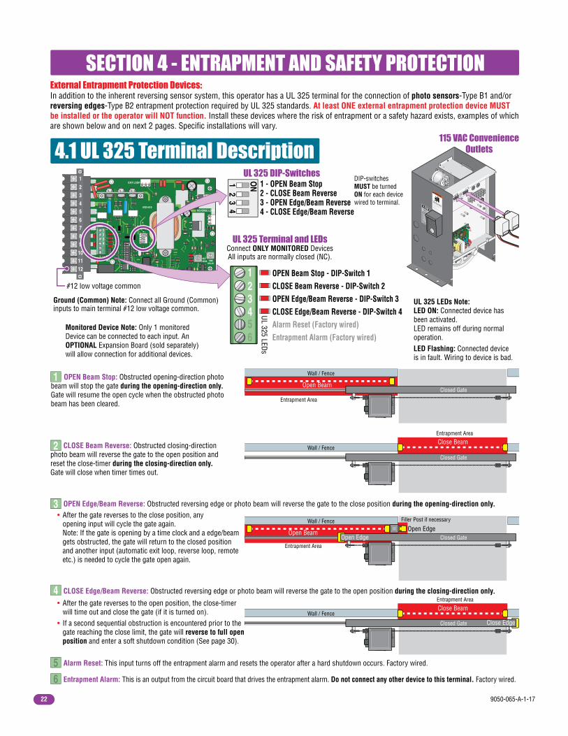
Ground (Common) Note: Connect all Ground (Common) inputs to main terminal #12 low voltage common.
115 VAC ConvenienceOutlets
OPEN Beam Stop - DIP-Switch 1CLOSE Beam Reverse - DIP-Switch 2OPEN Edge/Beam Reverse - DIP-Switch 3CLOSE Edge/Beam Reverse - DIP-Switch 4Alarm Reset (Factory wired)Entrapment Alarm (Factory wired)
SECTION 4 - ENTRAPMENT AND SAFETY PROTECTION
4.1 UL 325 Terminal Description
123456
Alarm Reset: This input turns off the entrapment alarm and resets the operator after a hard shutdown occurs. Factory wired.5 Entrapment Alarm: This is an output from the circuit board that drives the entrapment alarm. Do not connect any other device to this terminal. Factory wired.6
1 ON
23
4
1 - OPEN Beam Stop2 - CLOSE Beam Reverse3 - OPEN Edge/Beam Reverse4 - CLOSE Edge/Beam Reverse
UL 325 Terminal and LEDsConnect ONLY MONITORED DevicesAll inputs are normally closed (NC).
UL 325 DIP-Switches
CLOSE Edge/Beam Reverse: Obstructed reversing edge or photo beam will reverse the gate to the open position during the closing-direction only.
• After the gate reverses to the open position, the close-timer will time out and close the gate (if it is turned on). • If a second sequential obstruction is encountered prior to the gate reaching the close limit, the gate will reverse to full open position and enter a soft shutdown condition (See page 30).
OPEN Edge/Beam Reverse: Obstructed reversing edge or photo beam will reverse the gate to the close position during the opening-direction only. • After the gate reverses to the close position, any opening input will cycle the gate again. Note: If the gate is opening by a time clock and a edge/beam gets obstructed, the gate will return to the closed position and another input (automatic exit loop, reverse loop, remote etc.) is needed to cycle the gate open again.
CLOSE Beam Reverse: Obstructed closing-direction photo beam will reverse the gate to the open position and reset the close-timer during the closing-direction only.Gate will close when timer times out.
1
2
3
4
OPEN Beam Stop: Obstructed opening-direction photo beam will stop the gate during the opening-direction only. Gate will resume the open cycle when the obstructed photo beam has been cleared.
Closed Gate
Wall / Fence
Open Beam
Entrapment Area
Closed Gate
Wall / FenceClose Beam
Entrapment Area
Wall / Fence Filler Post if necessary
Closed GateOpen EdgeOpen Edge
Entrapment Area
Open Beam
Closed Gate
Wall / Fence
Close Edge
Entrapment Area
Close Beam
DIP-switches MUST be turned ON for each device wired to terminal.
Monitored Device Note: Only 1 monitored Device can be connected to each input. An OPTIONAL Expansion Board (sold separately) will allow connection for additional devices.
External Entrapment Protection Devices:In addition to the inherent reversing sensor system, this operator has a UL 325 terminal for the connection of photo sensors-Type B1 and/or reversing edges-Type B2 entrapment protection required by UL 325 standards. At least ONE external entrapment protection device MUST be installed or the operator will NOT function. Install these devices where the risk of entrapment or a safety hazard exists, examples of which are shown below and on next 2 pages. Specific installations will vary.
#12 low voltage common
UL 325 LEDs Note:LED ON: Connected device has been activated.LED remains off during normal operation.LED Flashing: Connected device is in fault. Wiring to device is bad.
UL 325 LEDs

9050-065-A-1-17 23
121110
9876
5432
1
NCNO
123456
Gate
Fra
me Ga
te F
ram
e
Non-Secure Side Outside Property
Secure Side Inside Property
Filler Post or Barrier
Reversing Edge (Open Contact Sensor)
4.2 Entrapment Protection Device LocationsTypical UL Photo Sensor mounting heightand distance away from gate.
If the distance between the gateand wall is greater than 2 1/4”.
Wall
UL s
enso
r mou
nted
on
post
.
UL s
enso
r mou
nted
on
wal
l.
A filler post or barrier may need to be installed between the gate and wall area to reduce the distance to 2 1/4” or less. A reversing edge should be installed on the post or barrier for safety (See page 2 for more information).
#12 Ground (Common) #12 Ground (Common)
Photo Sensor Power Note: Photo sensors can be powered by the built-in convenience outlets located on the operator (See previous page).
MainTerminal
Photo sensors may be installed on either side of gate frame, as close as practical to the gate but no further away than 5”.
No higher than 27.5” above grade.
21” is typical for most installations.
Note: Additional photo sensors can be added above the 27.5” height.
5”or
Less
5”or
Less
Photo Sensors (With Filler Post and Reverse Edge) Sample Setup
Closed Gate
WallClose Beam
Open Beam
UL 325 DIP-Switches
DIP-switches1, 2 and 3 ON
1 ON
23
4
UL 325 TerminalConnect ONLY MONITORED Devices
1 - OPEN Beam2 - CLOSE Beam3 - OPEN Edge/Beam4 - CLOSE Edge/Beam
IMPORTANT: Photo sensors must use Normally Closed (NC) contacts with the beam set for light operate (relay activated when beam is not obstructed).Only 1 monitored Device can be connected to each
input. An OPTIONAL Expansion Kit (sold separately) will allow connection for additional devices.
1 - OPEN Beam STOP (Switch 1)
2 - CLOSE Beam REVERSE (Switch 2)
3 - OPEN Edge/Beam REVERSE (Switch 3)
4 - CLOSE Edge/Beam REVERSE (Switch 4)
Filler Post If necessary
Open Edge
Normally Closed
Normally Closed
4702
123456
Normally Closed
9050-065-A-1-1724
NCNO
123456
121110
9876
5432
1
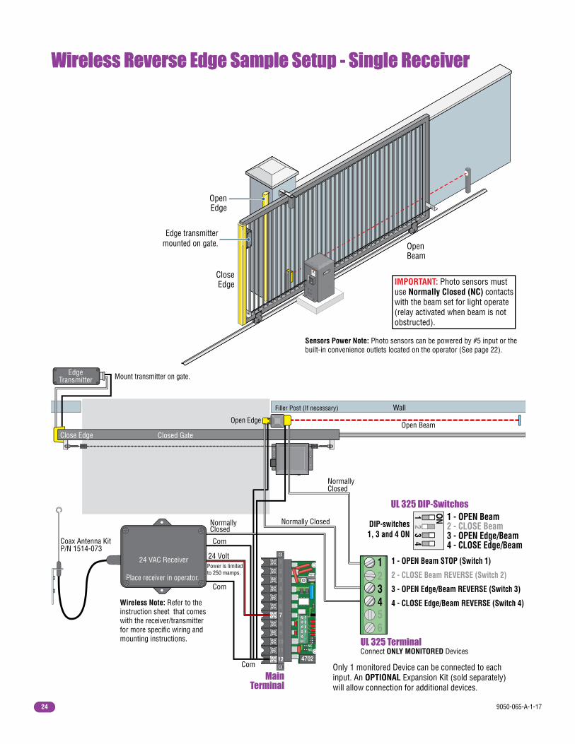
Wireless Reverse Edge Sample Setup - Single Receiver
Open Beam
Wireless Reverse Edge Sample Setup - Single Receiver
Closed Gate
Wall
Wireless Note: Refer to the instruction sheet that comes with the receiver/transmitter for more specific wiring and mounting instructions.
Close Edge
Mount transmitter on gate.
Filler Post (If necessary)
EdgeTransmitter
Coax Antenna KitP/N 1514-073
Com
Com
Com
24 VoltPower is limited to 250 mamps.
MainTerminal
UL 325 DIP-Switches
IMPORTANT: Photo sensors must use Normally Closed (NC) contacts with the beam set for light operate (relay activated when beam is not obstructed).
Open Edge
Normally Closed
NormallyClosed
Normally Closed
CloseEdge
OpenEdge
Edge transmitter mounted on gate. Open
Beam
Only 1 monitored Device can be connected to each input. An OPTIONAL Expansion Kit (sold separately) will allow connection for additional devices.
Sensors Power Note: Photo sensors can be powered by #5 input or the built-in convenience outlets located on the operator (See page 22).
WARNING
MOVING GATE CAN CAUSE
Operate gate only when gate area is in sight
and free of people and obstructions.
Do not allow children to play in gate area
or operate gate.Do not stand in gate path or walk through
path while gate is moving.
Read owner’s manual and safety instructions.
SERIOUS INJURY OR DEATH
CLASS
CERTIFIED TO
CAN/CSA C22.2 NO. 247
CONFORMS TO
ANSI/UL-325
VEHICULAR GATE OPERATORHP
53382
MODELSERIALVOLTS
PHASE
AMPS
60 Hz
MAX GATE LOADDoorKing, Inc., Inglewood, CA
DIP-switches1, 3 and 4 ON
1 ON
23
4
UL 325 TerminalConnect ONLY MONITORED Devices
1 - OPEN Beam2 - CLOSE Beam3 - OPEN Edge/Beam4 - CLOSE Edge/Beam
1 - OPEN Beam STOP (Switch 1)
2 - CLOSE Beam REVERSE (Switch 2)
3 - OPEN Edge/Beam REVERSE (Switch 3)
4 - CLOSE Edge/Beam REVERSE (Switch 4)
24 VAC Receiver
Place receiver in operator.
4702
123456
9050-065-A-1-17 25
NCNO TIME
DELAY
REVSENS
REVERSE LOOP
EXIT LOOP
4702-010
123456
1 ON
23
4
ON
12
34
56
78
4
Reverse
4 Ft. min. to avoid gate
movement interference.
4 Ft. min. to avoid gate
movement interference.4 Ft. min. to avoid reverse
loop interference.
Reverse
Automatic Exit
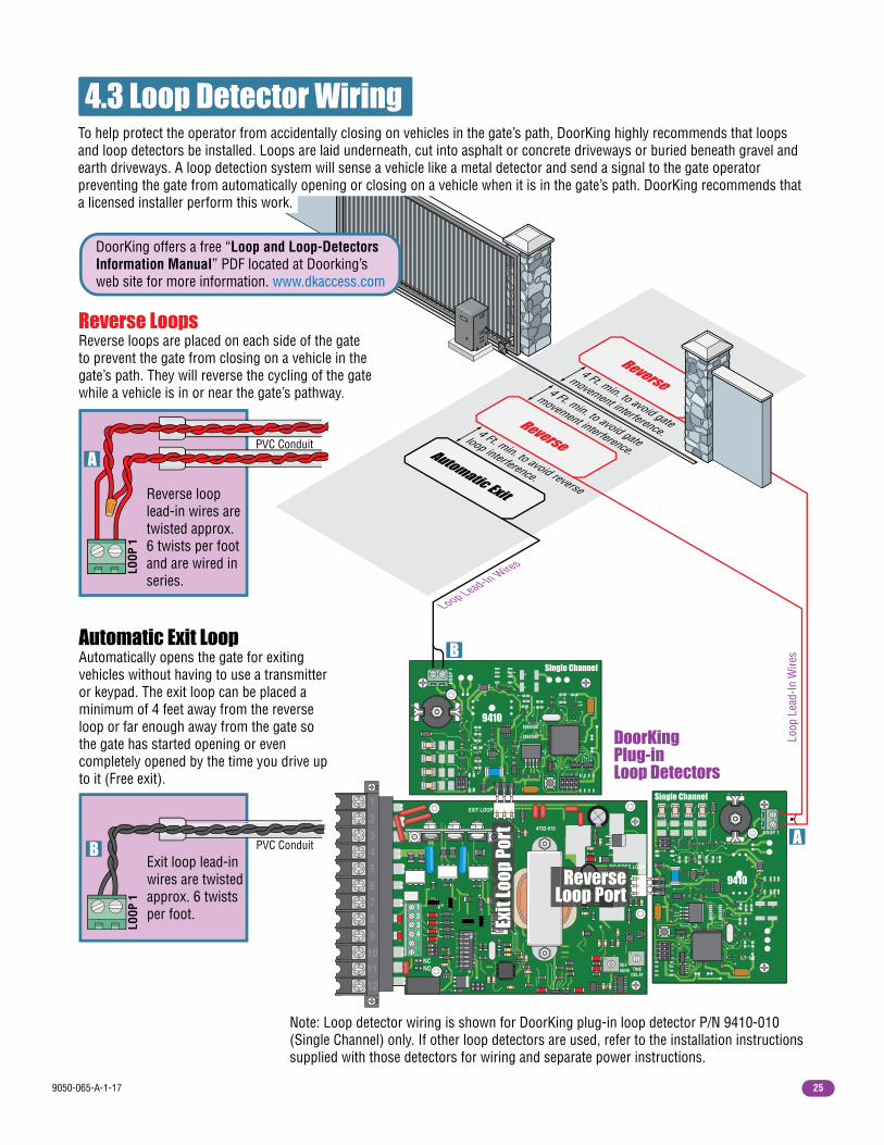
Note: Loop detector wiring is shown for DoorKing plug-in loop detector P/N 9410-010 (Single Channel) only. If other loop detectors are used, refer to the installation instructions supplied with those detectors for wiring and separate power instructions.
4.3 Loop Detector Wiring
Loop Lead-In Wires
DoorKingPlug-inLoop Detectors
B
L1
L1
L2
121110
9876
5432
1
9410
9410
Single Channel
Single Channel
A
Loop
Lea
d-In
Wire
s
Reverse LoopsReverse loops are placed on each side of the gate to prevent the gate from closing on a vehicle in the gate’s path. They will reverse the cycling of the gate while a vehicle is in or near the gate’s pathway.
To help protect the operator from accidentally closing on vehicles in the gate’s path, DoorKing highly recommends that loops and loop detectors be installed. Loops are laid underneath, cut into asphalt or concrete driveways or buried beneath gravel and earth driveways. A loop detection system will sense a vehicle like a metal detector and send a signal to the gate operator preventing the gate from automatically opening or closing on a vehicle when it is in the gate’s path. DoorKing recommends that a licensed installer perform this work.
Reverse loop lead-in wires are twisted approx. 6 twists per foot and are wired in series.
A
LOOP
1
PVC Conduit
Automatic Exit LoopAutomatically opens the gate for exiting vehicles without having to use a transmitter or keypad. The exit loop can be placed a minimum of 4 feet away from the reverse loop or far enough away from the gate so the gate has started opening or even completely opened by the time you drive up to it (Free exit).
B
LOOP
1
PVC ConduitExit loop lead-in wires are twisted approx. 6 twists per foot.
DoorKing offers a free “Loop and Loop-Detectors Information Manual” PDF located at Doorking’s web site for more information. www.dkaccess.com
1 ON
23
REVERSE
Exit
Loop
Por
t
ReverseLoop Port

9050-065-A-1-1726
NCNO
123456
DANGERHIGH VOLTAGE!
5.1 Main Terminal Description
Low Voltage Common
Dry Relay Contact
Earth Ground
Circuit Board Power
Circuit Board Power
Motor
Motor
Built-In SolenoidLock Power
Full Open
Dry Relay Contact
Standard Reverse
• When gate is closed, this input will open gate to full position.
• When gate is open and auto close timer Switch 2 is turned ON, input will re-set and hold timer.
• When gate is open and auto close timer Switch 2 is turned OFF, input will close gate.
• When gate is closing, input will reverse gate.
• When gate is open and auto close timer Switch 2 is turned ON, input will re-set and hold timer.
• When gate is open and auto close timer Switch 2 is turned OFF, input will prevent gate from closing.
• When gate is closing, input will reverse gate.
• This input ONLY functions when gate is fully open or in the closing cycle.
• Operation of relay is dependent on setting of switch 3.
• When Switch 3 is turned ON, relay activates when gate is in the full open position.
• When Switch 3 is turned OFF, relay is activated when gate IS NOT closed.
Relay contacts can be set for Normally Open (NO) or Normally Closed (NC) operation. Contact rating is 1 amp maximum at 24-volts DC.
8
121110
98766
55443322
1
9
1011
NC
NO
SECTION 5 - MAIN TERMINAL WIRING
24 VAC - 250 mamp. max.
UL 325Terminal
Pages22-24
ON
12
34
56
78
ON
12
34
56
78
ON
12
34
56
78
4702
Main Terminal Input LEDs Note: The LED that is beside the main terminal #8 and #9 wiring input will light when that terminal input gets activated.
#8
#9
9050-065-A-1-17 27
NCNO
123456
121110
9876
5432
1
5.2 Control Wiring for Single/Primary Operator
Key Switch
Stand-AloneKeypad
Stand-AloneCard Reader
TelephoneEntry
Fire Box
Note: All stand-alone, telephone entry and photo sensor devices must use a separate power source.
Com
Com
Relay
24 Volt, 250 mamp. Max.3-Wire Radio Receiver
Relay Com
Relay N.O.
N.O.
24 Volt Power Com
24 Volt Power4-WireRadioReceiver
WARNING
MOVING GATE CAN CAUSE
Operate gate only when gate area is in sight
and free of people and obstructions.
Do not allow children to play in gate area
or operate gate.Do not stand in gate path or walk through
path while gate is moving.
Read owner’s manual and safety instructions.
SERIOUS INJURY OR DEATH
CLASS
CERTIFIED TO
CAN/CSA C22.2 NO. 247
CONFORMS TO
ANSI/UL-325
VEHICULAR GATE OPERATORHP
53382
MODELSERIALVOLTS
PHASE
AMPS
60 Hz
MAX GATE LOADDoorKing, Inc., Inglewood, CA
Important: Controls intended for user activation must be located at least six (6) feet away from any moving part of the gate and where the user is prevented from reaching over, under, around or through the gate to operate the controls. Reset buttons must be located in the line-of-sight of the gate and no further than 50 feet from the gate. Emergency access controls only accessible by authorized personnel (e.g., fire, police, EMS) may be placed at any location in the line-of-sight of the gate.
4702

9050-065-A-1-1728
NCNO
123456
NCNO
123456
121110
9876
5432
1
NCNO
UL 325Terminal
Open BeamClose BeamOpen Edge
NO
121110
9876
5432
1
Open BeamClose BeamOpen Edge
47024702
Interconnection CableSold separately from DoorKing.
6 wires used (8 - 18 AWG wires total).External Loop DetectorsDKS plug-in loop detectors CANNOT be used in this primary / secondary arrangement. Use external detectors that have a normally open (N.O.) relay contact. Loop detectors must use a separate power source.
Reverse loop lead-in wires are wired in series.
AutomaticExit Loop
ReverseLoop
ReverseLoop
Seco
ndar
y Op
erat
or
Prim
ary
Oper
ator
24 Volt Power 250 mamp. max.
Relay
Com
#8 Y
ello
w
#8 Y
ello
w
#9 Brown
#9 Brown
#12 Orange
#12 Orange
Green toprimaryoperatorchassisground.
Green tosecondary
operatorchassisground.
Purple to Close Beam #2
BlueBlue
Red
to O
pen
Edge
#3
Red to Open Edge #3
GrayGray
Purp
le to
Clo
se B
eam
#2
Com
N.O.
N.O.
3-Wire Receiver4-wire receiver wiring, see page 27.
Note: Connect other opening devices to primary main terminal #8 and #12 as required (See page 27). They must use a separate power source if power is required.
• Requires AC power to each operator.
• Both operator DIP-switches must to be set.
• Connect all control devices, auxiliary devices and loops to the primary operator only.
5.3 Bi-Parting Gates Wiring - Dual Gate Operators
To Close Beam #2
To Open Edge #3 To Open Edge #3
To Common Main Terminal #12 To Common Main Terminal #12
To Common Main Terminal #12
Fence
Gate
Close Beam
Open Edge Open Edge Fence
Gate
Entrapment Protection Devices for Bi-Parting Gates• Separate power source for photo sensor (See page 22).
PrimaryOperator
SecondaryOperator
Open Beam Note:If Open beam is required for entrapment protection, #1 UL 325 terminal MUST be wired in parallel between primary and secondary operators.

9050-065-A-1-17 29
SECTION 6 - OPERATING INSTRUCTIONS
WARNING - To reduce the risk of injury or death: 1. READ AND FOLLOW ALL INSTRUCTIONS. 2. Never let children operate or play with gate controls. Keep the remote control away from children. 3. Always keep people and objects away from gate. NO ONE SHOULD CROSS THE PATH OF THE MOVING GATE. 4. Test the operator monthly. The gate MUST reverse on contact with a rigid object or stop or reverse when an object activates the non-contact sensors. After adjusting the force or the limit of travel, retest the gate operator. Failure to adjust and retest the gate operator properly can increase the risk of injury or death. 5. Use the emergency release only when the gate is not moving and power has been shut-off. 6. KEEP GATES PROPERLY MAINTAINED. Read the owner's manual. Have a qualified service person make repairs to gate hardware. 7. The entrance is for vehicles only. Pedestrians must use separate entrance. 8. SAVE THESE INSTRUCTIONS.
Unlock the power switch cover and open to access the Main Power, and the operator Reset Button.
AC POWER
OFF
RE
SE
T
6.1 AC Power Switch and Reset Button
Reset Button - Used to turn off the entrapment alarm and to reset the operator after a HARD shutdown has occurred. Alarm Siren AC Power Switch - Powers the operator ON (toggle up) or OFF (toggle down).
IMPORTANT SAFETY INSTRUCTIONS
WARNING
MOVING GATE CAN CAUSE
Operate gate only when gate area is in sight
and free of people and obstructions.
Do not allow children to play in gate area
or operate gate.
Do not stand in gate path or walk through
path while gate is moving.
Read owner’s manual and safety instructions.
SERIOUS INJURY OR DEATH
CLASS
CERTIFIED TO
CAN/CSA C22.2 NO. 247
CONFORMS TO
ANSI/UL-325
VEHICULAR GATE OPERATOR HP
53382
MODEL SERIAL VOLTS
PHASE
AMPS
60 Hz
MAX GATE LOAD DoorKing, Inc., Inglewood, CA
Every time the operator is powered up, the First open command will automatically run “Multiple gate cycles” that will locate and remember the gate’s open and close positions (See page 20).
Important: The operator WILL NOT lose its open and close limit positions after pressing the reset button.

9050-065-A-1-1730
6.2 Shutdown ConditionsUnder various entrapment conditions the operator will assume either a soft or hard (alarm) shutdown. To determine what type of reset action is required, you will need to understand how the different entrapment conditions affect the gate operator.
This occurs in various situations where the inherent or external entrapment protection devices have been activated. In a soft shutdown condition, the operator will not respond to any input that was present when the entrapment protection device sensed an obstruction. If the gate stops at the open position, the operator will not respond to the automatic close timer.
Note: In some systems, the time clock input comes from the telephone entry system relay. This same relay may also provide open commands for a card reader, MicroPLUS transmitters and the visitor telephone entry. If so, these devices will also be disabled in a soft shutdown condition.
In some conditions, a soft shutdown will reset as soon as the entrapment condition clears. For example, if a non-contact sensor (photo cell) is sensing an obstruction, the operator will stop the gate and assume a soft shutdown condition. When the photocell clears, the operator will return to normal operation.
When the operator is in a soft shutdown, activation of any "intended input" will reset the operator. An "intended input" includes any command, any standard safety input and any loop input. Activating any of these inputs will reset the gate. At that point the gate will return to normal operation. If the gate is open, the automatic close timer will then time out and close the gate.
• Example 1 - A time clock keys the gate open in the morning and an entrapment protection device senses an obstruction prior to the gate reaching the full open position. If the entrapment is sensed by the inherent system, the gate will reverse and run back to the closed position. The time clock input is still present, but the gate will not re-open.
• Example 2 - If the gate is closing and an entrapment protection device is activated, the gate will either stop or reverse and run back to the open position, depending upon if the secondary or inherent device was activated. The automatic close timer will not close the gate.
• Example 3 - Vehicle arrives at exit loop and gate runs towards the open position. If the inherent entrapment protection gets activated during this opening cycle, the gate reverses and runs back to the closed position. After the inherent entrapment protection is cleared, If the vehicle is still present at the exit loop, a soft shutdown condition does not occur. The exit loop input provides an immediate reset of the operator and the gate will again run to the open position.
Soft Shutdown
Resetting a Soft Shutdown
A hard shutdown condition occurs when: (1.) The inherent entrapment protection system (Type A) gets activated TWO consecutive times before the gate completes the open or close cycle. (2.) The reversing edge (Type B2) gets activated and reverses but before the gate completes the reverse cycle the inherent entrapment protection system (Type A) gets activated.
Hard Shutdown (Alarm Activated)
• Example of a Hard Shutdown - The gate is closing and the inherent entrapment protection system senses an obstruction and causes the gate to reverse direction. As the gate begins to run in the open direction, a second obstruction is sensed prior to the gate reaching the full open position. Once the second obstruction has been sensed, the operator will stop, the audio alarm will sound and all standard inputs are shut down (including open commands, safety commands, loop inputs, etc.).
– To silence the alarm, press the reset button or after 5 minutes, the audio alarm will shut off but will “chirp” every 5 seconds. This indicates that the operator is in a hard shutdown condition (The reset button must be pressed to reset the operator and stop the alarm “chirping”).

9050-065-A-1-17 31
6.3 Manual Gate Operation
Fail-Safe Manual Release System (Factory Installed)
This operator is equipped with one of two types of manual release systems, “Fail-Safe” (required by many city codes) or “Fail-Secure” that will allow the gate to be pushed open in the event of a power outage or equipment failure.
This manual release system is the most reliable and safest method for placing the gate operator in manual operation. It is the preferred method of emergency gate operation under worse case conditions by many Fire Chiefs and Building Inspectors and is typically used in Class I and Class II applications. This system is accessible from either side of the gate and requires NO keys, cranks or other tools to manually operate the gate. This prevents any delays for emergency vehicle access in the event of a power outage. The operator “Fails” (Loss of AC power) in a “Safe” (Manually operable) condition.
Note: DoorKing operators have a built-in alarm reset push button mounted on the operator above the power ON-OFF toggle switch. Activating this button will return the gate operator to normal operation, but will not cycle the gate operator. A remote alarm/reset station (P/N 1404-080) can be mounted external of the gate operator provided that it is installed in the line-of-sight of the gate and gate operator.
Solenoid lock does NOT secure the clutch plate during an AC power failure or turning AC power off. Gate can be immediately manually operated during these conditions.
Solenoid lock WILL retract and secure the clutch plate during normal operation ONLY if operator senses an unauthorized manual open attempt. Gate will NOT be allowed to move.
The operator is in a hard shutdown condition when the audio alarm is sounding OR “chirping” every 5 seconds.
Once the gate has been reset, an open or close command is needed to start the gate operator. Most activating commands will cause the gate operator to cycle to the open position. This includes activation of a key switch or open command and activation of an automatic exit loop. Activation of a close command will run the gate to the closed position.
• Before resetting a hard shutdown, determine why the shutdown occurred. Inspect the gate for any obstructions along its path that could have activated the inherent entrapment sensing system. Inspect the gate and gate hardware.
The gate operator WILL NOT lose its open and close positions after resetting a hard shutdown.
Resetting a Hard Shutdown
Caution: Never attempt to manually push open any gate with an operator attached to it until you have verified that power to the operator has been shut-off.
Solenoid Lock Clutch Plate
Switch 4 must be OFF.
The audio alarm will sound for five minutes, or until the operator’s reset button is pushed. After (5) five minutes the alarm will “chirp every 5 sec.” and the hard shutdown condition will remain in affect until the reset button is pushed.
ON
12
34
56
78

9050-065-A-1-1732
Key Release
Emergency Vehicle Access Conditions
Fail-Secure Manual Release System (Owner Installed)This manual release system (Installed 2600-862 Fail-Secure Manual Release Kit) allows the gate to be manually operated ONLY after unlocking the gate operator. Power outages or turning power off WILL NOT allow gate to be manually operated without physically unlocking the gate operator with the key first. This option is typically used in Class III and Class IV applications. The gate operator “Fails” (Loss of AC power) in a “Secure” (Manually in-operable) condition.
Solenoid lock does NOT allow the clutch plate to rotate when: • The AC power is on but the operator is not cycling. • The AC power is turned off. • AC power failure.
1. During normal AC powered operation, emergency vehicles access the gate by a separate emergency access device individually installed and wired to your gate system. The type of devices that can be used in your commu-nity depends on your city codes. These devices may include (but are not limited to) Fire Department lock boxes, Click-2-Enter radio receivers, strobe light sensors, siren sensors, etc. 2. In the event of an AC power failure, the emergency vehicle access device will not function because the gate operator is un-powered. “Fail-Safe” or “Fail-Secure” release systems for the gate operator allow the gate to be manually operated during AC power failure. ONLY the “Fail-Safe” release system allows the gate to be manually operated without unlocking the operator first and has been designed that way to allow emergency personnel to immediately manually operate the gate from either side under emergency situations.
This automatic vehicular gate system is designed to allow access to emergency vehicles under different operating conditions.
Solenoid Lock Clutch Plate
Clutch Plate Operator Housing
Solenoid lock automatically retracts and allows clutch plate to rotate ONLY during normal gate cycling.
Turning key 1/2 turn retracts solenoid lock and allows clutch plate to rotate for manual operation with or without AC power.
WARNING
MOVING GATE CAN CAUSE
Operate gate only when gate area is in sight
and free of people and obstructions.
Do not allow children to play in gate area
or operate gate.
Do not stand in gate path or walk through
path while gate is moving.
Read owner’s manual and safety instructions.
SERIOUS INJURY OR DEATH
CLASS
CERTIFIED TO
CAN/CSA C22.2 NO. 247
CONFORMS TO
ANSI/UL-325
VEHICULAR GATE OPERATOR HP
53382
MODEL SERIAL VOLTS
PHASE
AMPS
60 Hz
MAX GATE LOAD DoorKing, Inc., Inglewood, CA
Switch 4 must be ON. Important: solenoid lock MUST be in position shown.
ON
12
34
56
78

9050-065-A-1-17 33
7.1 Maintenance
SECTION 7 - MAINTENANCE AND TROUBLESHOOTINGInspection and service of this gate operator by a qualified technician should be performed anytime a malfunction is observed or suspected. High cycle usage may require more frequent service checks.
When servicing the gate operator, always check any external reversing devices (loops, photocells, etc.) for proper operation.If external reversing devices cannot be made operable, do not place this operator in service until the malfunction can be identified and corrected.
Always check the inherent reversing system when performing any maintenance. If the inherent reversing system cannot be made operable, remove this operator from service until the cause of the malfunction is identified and corrected. Keeping this operator in service when the inherent reversing system is malfunctioning creates a hazard for persons which can result in serious injury or death should they become entrapped in the gate.
When servicing this gate operator, always turn power OFF!!
Operator Component
Maintenance Monthly Interval
6 3 12
Alarm
Chain
Drive Belt
✓
✓
✓ ✓
✓ ✓
✓
✓
✓ ✓
✓
Fire Dept.
Gate
Loop(s)
Release
Inherent Reverse System
External Reverse Device
Complete System
Activate the inherent reverse system by blocking the gate with a solid object. When the gate reverses, block the gate in the opposite direction prior to the limit being reached. The entrap-ment alarm should activate. Press the reset button to silence the alarm.
Check for sagging. Tighten if necessary.
Clutch Check for proper slippage when an obstruction is encountered.
Check for alignment, tightness and wear.
Check vehicular exit and reverse loops for proper operation.
Check manual release for proper operation.
Pulleys Check for alignment. Check setscrews.
Complete check of gate and gate operating system.
Check emergency vehicle access device for proper operation.
Grease Wheels and guide rollers if necessary.
Inspect for damage. Check gate wheels. rollers and guides for wear and grease if necessary.
Check that the gate reverses on contact with an object in both the opening and closing cycles. Adjust the reversing sensor and/or clutch if necessary.
Check external reverse device(s) stop or reverse the gate when activated.
✓ ✓
Align clutch plate holes with screws to repair solenoid lock.
DO NOT
remove clutch
plate.
RemovePulley Assembly
Every time the operator is powered up, the First open command will automatically run “Multiple gate cycles” that will locate and remember the gate’s open and close positions (See page 20).

9050-065-A-1-1734
7.2 TroubleshootingHave a good VOM meter to check voltages and continuity. A Meg-Ohm meter capable of checking up to 500 meg-ohms of resistance is necessary to properly check the integrity of the ground loops. When a malfunction occurs, isolate the problem to one of three areas: 1. the operator, 2. the loop system, 3. the keying devices. Use caution when checking high voltage terminals, motor capacitor and the motor.
1. Check the input indicator LEDs. They should only come ON when a keying device (card reader, push button, etc.) is activated. If any of the input LEDs are ON continuously, this will cause the gate operator to hold open. Disconnect the keying devices one at a time until the LED goes OFF.
2. Check any external entrapment protection devices. Any short or malfunction in these devices can cause the gate operator to stop or to hold open.
3. A malfunction in a loop or loop detector can cause the gate operator to hold open, or to not detect a vehicle when it is present over the loop. Pull the loop detector circuit boards from the loop ports on the operator circuit board. If the malfunction persists, the problem is not with the loop system. For more information on trouble shooting loops and loop detectors, refer to your loop detector instruction sheet and to the DoorKing Loop and Loop Detector Information Manual.
4. Check to be sure that there are no shorted or open control wires from the keying devices to the gate operator. If a keying device fails to open the gate, momentarily jumper across terminals 8 and 12 on the operator circuit board. If the gate operator starts, this indicates that a problem exist with the keying device and is not with the gate operator.
5. Check the high voltage supply. A voltage drop on the supply line (usually caused by using too small supply voltage wires) will cause the operator to malfunction. Refer to the wire size chart in section 2.1, page 17.
Symptom Possible Solution(s)
• Check that AC power to the operator is turned ON. • Transformer may be overheated. Turn power off and allow board to cool for several minutes then retest. Check for low 115 VAC power and low voltage shorts. • Check for 115 VAC at high voltage terminal. If voltage measures 0, check the terminal strip or replace the circuit board.
• If a photo sensor is used as a entrapment protection device, check to be sure that the beam is not blocked.• Momentarily jumper terminal 8 to terminal 12. If the input LED does not come ON, check the terminal strip or replace the circuit board. If LED does come ON, proceed to next steps.• Be sure that the chain is not too tight. A too tight chain may cause the operator to stall.• Bypass circuit board and Check Motor: Turn power switch OFF and remove the circuit board. 1. Place a jumper wire from terminal 3 to terminal 4. CAUTION – HIGH VOLTAGE. Turn the power switch on. The motor should run. Turn the power switch OFF and remove the jumper. 2. Place a jumper wire from terminal 3 to terminal 5. CAUTION – HIGH VOLTAGE. Turn the power switch on. The motor should run in the opposite direction. Turn the power switch off and remove the jumper.• If the motor runs in both steps above, replace the control board. If the motor does not run, or runs in only one direction, problem can be a bad motor, motor capacitor, motor resistors, wire connections from the control board to the motor or a bad control board.
Operator will not run. Power LED is OFF.
Operator will not run. Power LED is ON.
Every time the operator is powered up, the First open command will automatically run “Multiple gate cycles” that will locate and remember the gate’s open and close positions (See page 20).

9050-065-A-1-17 35
Symptom Possible Solution(s)
• Check the input LEDs. Any ON will hold the gate open and indicates a problem with a keying device.• Check the external safety devices. Any activated will hold the gate open and indicates a problem with the safety device.• Check the loop detectors. Any activated can hold the gate open and indicates a problem with the loop detector or ground loop.• Operator may be in a “soft shutdown.” Activate any keying device to determine if operator returns to normal operation.• If automatic close is desired, be sure Switch 2 is ON and set timer open from 1-23 seconds.• Bypass circuit board and check motor as described on previous page.
Gate opens but will not close.
Gate closes but will not open.
• Operator may be in a “soft shutdown.” Check input LEDs. If any are ON, momentarily disconnect, then re-connect the wire going to the respective terminal. Operator should open. • Check to be sure that the operator is running in the proper direction. Turn power OFF, and then back ON. Activate a keying device. Operator should run in the open direction. If operator runs in the close direction, turn power OFF and change direction of Switch 1. Go to above section if operator now opens but will not close. • Be sure that the each LED on the control board lights when the keying device connected to the that terminal is activated. If LED does not light, momentarily place a jumper wire from terminal 12 to the input terminal being checked. If LED lights and gate opens, problem is with the keying device. If LED does not light, replace control board. • Bypass circuit board and check motor as described on previous page.
• Check that the clutch is adjusted properly and is not slipping.• Disconnect the gate from the gate operator and check that the gate slides freely without any binding.• Re-adjust the reverse sensitivity.• Check that the magnetic pickup transistors on control board are not obstructed by excess wires. Electrical interference from excess wires can diminish magnetic field.• Check that the magnetic pickup transistors on control board are within 1/8 inch of the clear plastic protective cover above the black plastic magnetic spring assembly on the main shaft.• Continue troubleshooting or replace the circuit board.
Gate opens a short distance, then stops and reverses.
Gate closes then re-opens.
Gate starts to close, then reverses to open.
Alarm chirps once every 5 seconds. Operator will not run.
Alarm is sounding. Operator will not run.
• Check that the clutch is adjusted properly and is not slipping.• Re-adjust the reverse sensitivity.• Disconnect the gate from the gate operator and check that the gate slides freely without any binding.• Check the loop detector LEDs and input LEDs. Any that flash ON will cause the gate to reverse.• Check the Magnetic Sensor LEDs on the circuit board. If either LED is not blinking as the operator is running, check that the magnetic pickup transistors are within 1/8 inch of the protective plastic cover above the magnet assembly on the main shaft.• Continue troubleshooting or replace the circuit board.
• Operator has been in a “hard shutdown” condition in excess of 5 minutes. Reset button must be pushed to return operator to normal operation, see Section 6.2 Shutdown Conditions, pages 30-31.
• Operator is in a “hard shutdown” condition. Reset button must be pushed to return operator to normal operation, see Section 6.2 Shutdown Conditions, pages 30-31.
• Check for any input or loop detector LED’s that are ON.• Check that the operator is running in the proper direction (see “gate closes but will not open”).• Turn power off, then back on to run multiple gate cycles to reset operator open and close positions.

9050-065-A-1-1736
7.3 Accessory ItemsUL 325 Monitored Entrapment Protection Devices available for model 9050 slide gate operator.
Type B2 Contact Sensors (Reversing Edge) Miller Edge Sensing Edges - all models with a T2 (resistive) termination. Miller Edge Monitored Gate Link Model MGL-K20 Type B1 Non-contact Sensors (Photo Cell) Miller Edge Reflective-Guard Model RG Miller Edge Prime-Guard Model PG EMX Industries Model IRB-MON EMX Industries Model IRB-RET Omron Model E3K-R10K4 Seco-Larm Model E-931-S50RRGQ Seco-Larm Model E-931-S33RRGQ Seco-Larm Model E-960-D90GQ Type B1 Non-contact Sensors (Photo Cell) requires DK P/N 9200-190 Photocell Resistor kit MMTC Model IR55 MMTC Model 60-278 Carlo Gavazzi Model PMP12 Carlo Gavazzi Model 8080-031 Monitored Expansion Kit Miller Edge Multi-Input Module Model MIM-62
Accessory items available for the model 9050 slide gate operator.
Contact Sensors - For use as a safety protection device. Miller Edge, Inc., MGO20, MGR20, MGS20Photo Cell - Non-contact (photocell) sensors for use as a safety protection device. MMTC, Inc. Model IR55 - P/N 8080-010 MMTC, Inc. Model 60-278 - P/N 8080-011 Carlo Gavazzi Type PMP12 - P/N 8080-030 Carlo Gavazzi Type PMT - P/N 8080-031Loop Detector - Detectors plug directly into ports on circuit board simplifying wiring. Single channel detector - P/N 9410-010 Dual channel detector - P/N 9409-010Loop Wire - 18 AWG loop wire with XLPE insulation is ideal for ground loops. Available in 500 and 1000 foot rolls. Red, blue or black insulation.Pre-Fab Loops - Prefabricated ground loops. 24-foot circumference with 50-foot lead-in. Available in yellow, red or blue jackets. Not for use in asphalt roadways.Loop Test Meter - Meg-ohm meter checks the integrity of ground loops. P/N 9401-045Interconnect Cable - Interconnect wire cable contains all the necessary wires to interconnect primary / secondary operators. Cable length: 30 ft. - P/N 2600-755 40 ft. - P/N 2600-756 50 ft. - P/N 2600-757Time Clock - 7 day and 365 day time clocks can be used to automatically open gate at pre-set time and days. Compact clock fits inside the operator. 7 day clock - P/N 2600-791 365 day clock - P/N 2600-795V-Wheels - 4 inch and 6 inch. UHMW or Steel. Roller bearings or sleeve bearings. Single or tandem wheel configurations.Endless Idler Assembly with Safety Cover - Use when gate operator chain needs 180° return. P/N 2600-818Guide Rollers with Safety Covers - A variety of sizes to support slide gates.Gate End Retainer - Fits on top of end post and helps stabilize the end of the gate in the open or closed position (End post not provided).P/N 1204-004Base Plate for 9050 - Required for post mount installation. P/N 2600-418Base Plate Stop Brackets for 9050 - Required for post mount installation when using chain stops. P/N 2600-970Additional #40 Chain - 20 ft. per box. P/N 2600-442 Fail-Secure Manual Release Kit - Changes the Fail-Safe manual release to a Fail-Secure manual release. P/N 2600-862Surge Devices - High and low voltage surge suppressors help prevent circuit board failure caused by lightning strikes and power surges. High Voltage - P/N 1876-010 Low Voltage - P/N 1878-010Speed Bumps - Prefabricated six-foot speed bump reduces traffic speed through gate system. P/N 1610-150

9050-065-A-1-17 37
NCNO TIME
DELAY
REVSENS
REVERSE LOOP
EXIT LOOP
4702-010
123456
1 ON
23
4
ON
12
34
56
78
4
Model 9050 1/2 HP 115 VAC
Reset
AC Power
Alarm
Blue
Blue
Blue
Red
Red
Red
White
White
Brown
Brown
Brow
n
Brow
n
Black
Black White
White
White
Red
Yellow
White
Green
White
Brown
Chassis Ground
Board Ground
MOV Assembly
115 VAC
NEUHOT
Convenience Outlets
Built-In Solenoid Lock
Power Neutral
Black
12 11 10
9 8 7 6
5 4 3 2
1
30uf Capacitor
Ground
1/2 HP4.3 Amp
MountingScrew

Installation/Owner’s Manual Model 9050Model 9050Model 9050
Copyright 2009 DoorKing, Inc. All rights reserved.
Use this manual for circuit board 4702-010 Revision AA or higher.
www.doorking.com
Vehicular Slide Gate Operator
DoorKing, Inc.120 S. Glasgow Avenue
Inglewood, California 90301U.S.A.
Phone: 310-645-0023Fax: 310-641-1586
THIS PRODUCT IS TO BE INSTALLED AND SERVICED BY A TRAINED GATE SYSTEMS TECHNICIAN ONLY. Visit www.dkslocator.com to find a professional installing and servicing dealer in your area.
EXTERNAL ENTRAPMENT PROTECTION MUST be installed or the gate operator WILL NOT function.
9050-065-A-1-17