installation/owner’s manual series 9200series 9200series 9200
TRANSCRIPT

Installation/Owner’s Manual Series 9200Series 9200Series 9200
Copyright 2009 DoorKing, Inc. All rights reserved.
TM
Copyright 2011 DoorKing, Inc. All rights reserved.
Use this manual for circuit board 4404-010 Revision A or higher.
Date Installed:
Installer/Company Name:
Phone Number:
Leave Manual with Owner
Heavy-Duty Vehicular Slide Gate Operator
UL 325 Compliant
Circuit BoardSerial Numberand Revision Letter:
WARNING
MOVING GATE CAN CAUSE
Operate gate only when gate area is in sight
and free of people and obstructions.
Do not allow children to play in gate area
or operate gate.Do not stand in gate path or walk through
path while gate is moving.
Read owner’s manual and safety instructions.
SERIOUS INJURY OR DEATH
CLASS
CERTIFIED TO
CAN/CSA C22.2 NO. 247
CONFORMS TO
ANSI/UL-325
VEHICULAR GATE OPERATORHP
53382
MODELSERIALVOLTS
PHASE
AMPS
60 Hz
MAX GATE LOADDoorKing, Inc., Inglewood, CA
9210-065-X-1-11

9210-065-X-1-11 1
DoorKing, Inc. reserves the right to make changes in the products described in this manual without notice and without obligation of DoorKing, Inc. to notify any persons of any such revisions or changes. Additionally, DoorKing, Inc. makes no representations or warranties with respect to this manual. This manual is copyrighted, all rights reserved. No portion of this manual may be copied, reproduced, translated, or reduced to any electronic medium without prior written consent from DoorKing, Inc.
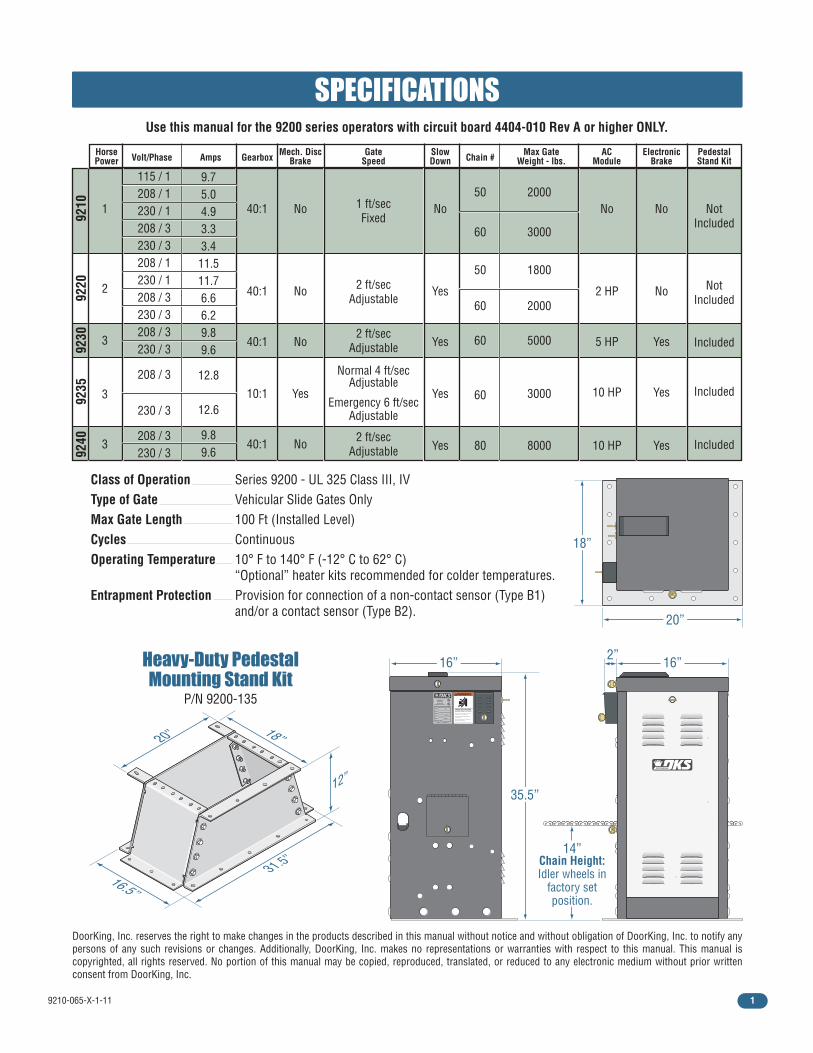
Class of Operation Series 9200 - UL 325 Class III, IV Type of Gate Vehicular Slide Gates OnlyMax Gate Length 100 Ft (Installed Level) Cycles ContinuousOperating Temperature 10° F to 140° F (-12° C to 62° C) “Optional” heater kits recommended for colder temperatures.Entrapment Protection Provision for connection of a non-contact sensor (Type B1) and/or a contact sensor (Type B2).
SPECIFICATIONS
16” 16”
20”
35.5”
14”Chain Height:Idler wheels in
factory set position.
18”
Max GateWeight - lbs.
ElectronicBrake
ACModule
SlowDown
Mech. DiscBrakeVolt/PhaseHorse
Power GearboxAmps Chain #
115 / 1208 / 1230 / 1208 / 3230 / 3208 / 1230 / 1208 / 3230 / 3208 / 3230 / 3
208 / 3
230 / 3
208 / 3230 / 3
1
2
3
3
3
40:1
40:1
40:1
10:1
40:1
No
No
No
Yes
No
No
Yes
Yes
Yes
Yes
50
60
2000
3000
NotIncluded
NotIncluded
Included
Included
Included
No
No
Yes
Yes
Yes
No
2 HP
5 HP
10 HP
10 HP
1 ft/secFixed
2 ft/secAdjustable
2 ft/secAdjustable
Normal 4 ft/secAdjustable
Emergency 6 ft/secAdjustable
2 ft/secAdjustable
9.75.04.93.33.4
11.511.76.66.29.89.6
12.8
12.6
9.89.6
WARNING
MOVING GATE CAN CAUSE
Operate gate only when gate area is in sightand free of people and obstructions.
Do not allow children to play in gate areaor operate gate.
Do not stand in gate path or walk throughpath while gate is moving.
Read owner’s manual and safety instructions.
SERIOUS INJURY OR DEATH
CLASS
CERTIFIED TOCAN/CSA C22.2 NO. 247
CONFORMS TOANSI/UL-325
VEHICULAR GATE OPERATOR
HP
53382
MODEL
SERIAL
VOLTS PHASE
AMPS 60 Hz
MAX GATE LOAD
DoorKing, Inc., Inglewood, CA
2”
9210
9220
9230
9235
9240
Heavy-Duty PedestalMounting Stand Kit
P/N 9200-135
16.5”
18”
12”
31.5”
20”
Use this manual for the 9200 series operators with circuit board 4404-010 Rev A or higher ONLY.
50
60
60
60
80
1800
2000
5000
3000
8000
GateSpeed
PedestalStand Kit

9210-065-X-1-112
SPECIFICATIONS 1
SECTION 1 - INSTALLATION 10
SECTION 2 - AC POWER TO OPERATOR(S) 17
Gate Construction
Important Safety Instructions
Instructions regarding intended installation:
Important Notices
UL325 Entrapment Protection
Glossary
Slide Gate Requirements
Slide Gate Protection
4
4
4
5
6
7
8
9
10
10
11-12
13
14-15
16
17
17
18
1.1 Gate Hardware
1.2 Underground Conduit Requirements
1.3 Installation Options, Gate Types
1.4 Installation #1
1.5 Installation #2, Chain Tray Kit
1.6 Chain Installation
1.7 Installation of Warning Signs
2.1 High Voltage Wire Runs
2.2 High Voltage Terminal Connection
SECTION 3 - ADJUSTMENTS 19
19
20-21
22
3.1 4404 Circuit Board Description and Adjustments
3.2 DIP-Switch SW 1 and SW 2 Settings
3.3 Limit Switches
TABLE OF CONTENTS

9210-065-X-1-11 3
29
30
31
32
5.1 Main Terminal Description
5.2 Control Wiring for Single/Primary Operator
5.3 Auxiliary Device Wiring
5.4 Bi-Parting Gates Wiring - Dual Gate Operators
23
23
24
3.4 Inherent Reverse Sensor Adjustment
3.5 Current Sensor Adjustment
3.6 AC Module Adjustment
SECTION 4 - ENTRAPMENT AND SAFETY PROTECTION 25
SECTION 5 - MAIN TERMINAL WIRING 29
SECTION 6 - OPERATING INSTRUCTIONS 33
SECTION 7 - MAINTENANCE AND TROUBLESHOOTING 36
4.1 UL 325 Terminal Description
4.2 Secondary Entrapment Protection Device Locations
4.3 Loop Detector Wiring
6.1 AC Power and Reset Button(s)
6.2 Shutdown ConditionsSoft Shutdown
Hard Shutdown
6.3 Manual Gate Operation
7.1 Maintenance
7.2 Built-In Diagnostic Tests
7.3 Troubleshooting
7.4 Accessory Items
25
26-27
28
36
37
37-38
39
35
33
34
TABLE OF CONTENTS
9210-065-X-1-114
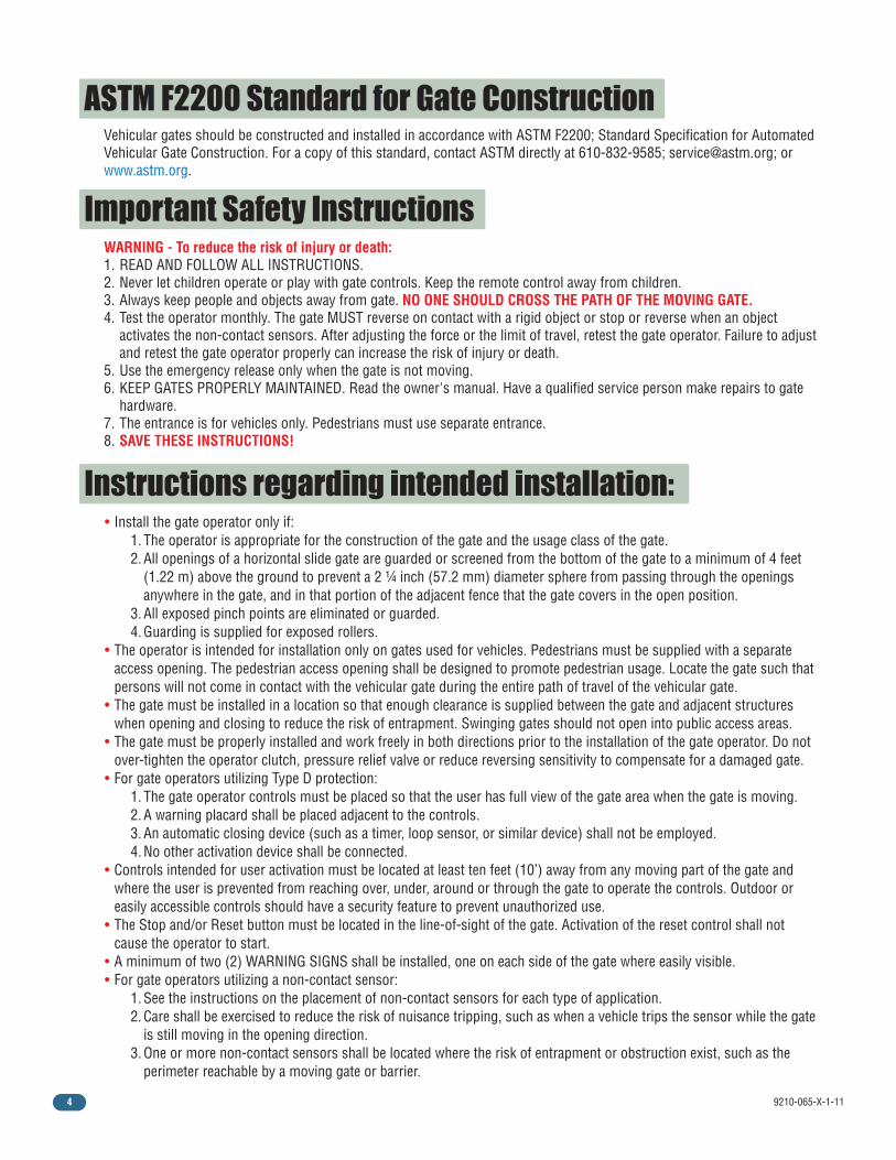
ASTM F2200 Standard for Gate Construction
Instructions regarding intended installation:
Vehicular gates should be constructed and installed in accordance with ASTM F2200; Standard Specification for Automated Vehicular Gate Construction. For a copy of this standard, contact ASTM directly at 610-832-9585; [email protected]; or www.astm.org.
Important Safety Instructions WARNING - To reduce the risk of injury or death: 1. READ AND FOLLOW ALL INSTRUCTIONS. 2. Never let children operate or play with gate controls. Keep the remote control away from children. 3. Always keep people and objects away from gate. NO ONE SHOULD CROSS THE PATH OF THE MOVING GATE. 4. Test the operator monthly. The gate MUST reverse on contact with a rigid object or stop or reverse when an object activates the non-contact sensors. After adjusting the force or the limit of travel, retest the gate operator. Failure to adjust and retest the gate operator properly can increase the risk of injury or death. 5. Use the emergency release only when the gate is not moving. 6. KEEP GATES PROPERLY MAINTAINED. Read the owner's manual. Have a qualified service person make repairs to gate hardware. 7. The entrance is for vehicles only. Pedestrians must use separate entrance. 8. SAVE THESE INSTRUCTIONS!
• Install the gate operator only if: 1. The operator is appropriate for the construction of the gate and the usage class of the gate. 2. All openings of a horizontal slide gate are guarded or screened from the bottom of the gate to a minimum of 4 feet (1.22 m) above the ground to prevent a 2 ¼ inch (57.2 mm) diameter sphere from passing through the openings anywhere in the gate, and in that portion of the adjacent fence that the gate covers in the open position. 3. All exposed pinch points are eliminated or guarded. 4. Guarding is supplied for exposed rollers. • The operator is intended for installation only on gates used for vehicles. Pedestrians must be supplied with a separate access opening. The pedestrian access opening shall be designed to promote pedestrian usage. Locate the gate such that persons will not come in contact with the vehicular gate during the entire path of travel of the vehicular gate. • The gate must be installed in a location so that enough clearance is supplied between the gate and adjacent structures when opening and closing to reduce the risk of entrapment. Swinging gates should not open into public access areas. • The gate must be properly installed and work freely in both directions prior to the installation of the gate operator. Do not over-tighten the operator clutch, pressure relief valve or reduce reversing sensitivity to compensate for a damaged gate. • For gate operators utilizing Type D protection: 1. The gate operator controls must be placed so that the user has full view of the gate area when the gate is moving. 2. A warning placard shall be placed adjacent to the controls. 3. An automatic closing device (such as a timer, loop sensor, or similar device) shall not be employed. 4. No other activation device shall be connected. • Controls intended for user activation must be located at least ten feet (10’) away from any moving part of the gate and where the user is prevented from reaching over, under, around or through the gate to operate the controls. Outdoor or easily accessible controls should have a security feature to prevent unauthorized use. • The Stop and/or Reset button must be located in the line-of-sight of the gate. Activation of the reset control shall not cause the operator to start. • A minimum of two (2) WARNING SIGNS shall be installed, one on each side of the gate where easily visible. • For gate operators utilizing a non-contact sensor: 1. See the instructions on the placement of non-contact sensors for each type of application. 2. Care shall be exercised to reduce the risk of nuisance tripping, such as when a vehicle trips the sensor while the gate is still moving in the opening direction. 3. One or more non-contact sensors shall be located where the risk of entrapment or obstruction exist, such as the perimeter reachable by a moving gate or barrier.
9210-065-X-1-11 5
• For gate operators utilizing contact sensors: 1. One or more contact sensors shall be located where the risk of entrapment or obstruction exist, such as at the leading edge, trailing edge, and post mounted both inside and outside of a vehicular horizontal slide gate. 2. One or more contact sensors shall be located at the bottom edge of a vehicular vertical lift gate. 3. One or more contact sensors shall be located at the pinch point of a vehicular vertical pivot gate. 4. A hardwired contact sensor shall be located and its wiring arranged so that the communication between the sensor and the gate operator is not subjected to mechanical damage. 5. A wireless contact sensor such as one that transmits radio frequency (RF) signals to the gate operator for entrapment protection functions shall be located where the transmission of the signals are not obstructed or impeded by building structures, natural landscaping or similar obstructions. A wireless contact sensor shall function under the intended end-use conditions. 6. One or more contact sensors shall be located at the bottom edge of a vertical barrier (arm).
Vehicular gate operator products provide convenience and security. However, gate operators must use high levels of force to move gates and most people underestimate the power of these systems and do not realize the potential hazards associ-ated with an incorrectly designed or installed system. These hazards may include: • Pinch points • Entrapment areas • Reach through hazards • Absence of entrapment protection devices • Improperly located access controls • Absence of vehicle protection devices • Absence of controlled pedestrian accessIn addition to these potential hazards, automated vehicular gate systems must be installed in accordance with the UL-325 Safety Standard and the ASTM F2200 Construction Standard. Most lay persons are unaware of, or are not familiar with, these standards. If an automated vehicular gate system is not properly designed, installed, used and maintained, serious injuries or death can result. Be sure that the installer has instructed you on the proper operation of the gate and gate operator system.Be sure that the installer has trained you about the basic functions of the required reversing systems associated with your gate operating system and how to test them. These include reversing loops, inherent reversing system, electric edges, photoelectric cells, or other external devices.
• This Owner’s Manual is your property. Keep it in a safe place for future reference.• Be sure that all access control devices are installed a minimum distance of 10 feet away from the gate and gate operator, or in such a way that a person cannot touch the gate or gate operator while using the device. If access control devices are installed in violation of these restrictions, immediately remove the gate operator from service and contact your installing dealer.• Loops and loop detectors, photo-cells or other equivalent devices must be installed to prevent the gate from closing on vehicular traffic.• The speed limit for vehicular traffic through the gate area is 5 MPH. Install speed bumps and signs to keep vehicular traffic from speeding through the gate area. Failure to adhere to posted speed limits can result in damage to the gate, gate operator, and to the vehicle.• Be sure that all persons who will use the gate system are familiar with the proper use of the gate and gate operator and are familiar with the possible hazards associated with the gate system.• Be sure that warning signs are permanently installed on both sides of the gate in an area where they are fully visible to traffic.• It is your responsibility to periodically check all entrapment protection devices. If any of these devices are observed to function improperly, remove the operator from service immediately and contact your installing or servicing dealer.• Follow the recommended maintenance schedule.• Do not allow children to play in the area of the operator or to play with any gate-operating device.• To remove the gate operator from service, operate the gate to the full open position and then shut off power to the operator at the service panel.
Important Notices
9210-065-X-1-116
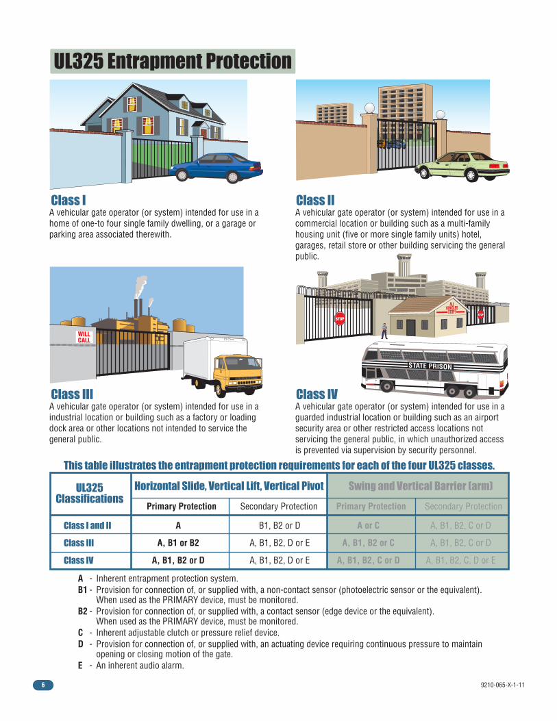
UL325 Entrapment Protection
Class I
Class I and II
Class III
Class IV
Class II
Class III Class IV
A vehicular gate operator (or system) intended for use in a home of one-to four single family dwelling, or a garage or parking area associated therewith.
A vehicular gate operator (or system) intended for use in a commercial location or building such as a multi-family housing unit (five or more single family units) hotel, garages, retail store or other building servicing the general public.
A vehicular gate operator (or system) intended for use in a industrial location or building such as a factory or loading dock area or other locations not intended to service the general public.
A vehicular gate operator (or system) intended for use in a guarded industrial location or building such as an airport security area or other restricted access locations not servicing the general public, in which unauthorized access is prevented via supervision by security personnel.
This table illustrates the entrapment protection requirements for each of the four UL325 classes.
A - Inherent entrapment protection system. B1 - Provision for connection of, or supplied with, a non-contact sensor (photoelectric sensor or the equivalent). When used as the PRIMARY device, must be monitored. B2 - Provision for connection of, or supplied with, a contact sensor (edge device or the equivalent). When used as the PRIMARY device, must be monitored. C - Inherent adjustable clutch or pressure relief device. D - Provision for connection of, or supplied with, an actuating device requiring continuous pressure to maintain opening or closing motion of the gate. E - An inherent audio alarm.
STATE PRISON
UL325 Classifications
Horizontal Slide, Vertical Lift, Vertical Pivot Swing and Vertical Barrier (arm)
Primary Protection
A B1, B2 or D A, B1, B2, C or D A or C
A, B1 or B2 A, B1, B2, D or E A, B1, B2, C or D A, B1, B2 or C
A, B1, B2 or D A, B1, B2, D or E A, B1, B2, C, D or E A, B1, B2, C or D
Secondary Protection Primary Protection Secondary Protection

9210-065-X-1-11 7
GlossaryGATE - A moving barrier such as a swinging, sliding, raising, lowering, or the like, barrier, that is a stand-alone passage barrier or is that portion of a wall or fence system that controls entrance and/or egress by persons or vehicles and completes the perimeter of a defined area.
RESIDENTIAL VEHICULAR GATE OPERATOR – CLASS I - A vehicular gate operator (or system) intended for use in a home of one-to four single family dwelling, or garage or parking area associated therewith.
COMMERCIAL / GENERAL ACCESS VEHICULAR GATE OPERATOR - CLASS II - A vehicular gate operator (or system) intended for use in a commercial location or building such as a multi-family housing unit (five or more single family units), hotels, garages, retail store, or other building servicing the general public.
INDUSTRIAL / LIMITED ACCESS VEHICULAR GATE OPERATOR - CLASS III - A vehicular gate operator (or system) intended for use in an industrial location or building such as a factory or loading dock area or other locations not intended to service the general public.
RESTRICTED ACCESS VEHICULAR GATE OPERATOR - CLASS IV - A vehicular gate operator (or system) intended for use in a guarded industrial location or building such as an airport security area or other restricted access locations not servicing the general public, in which unauthorized access is prevented via supervision by security personnel.
VEHICULAR BARRIER (ARM) OPERATOR (OR SYSTEM) - An operator (or system) that controls a cantilever type device (or system), consisting of a mechanical arm or barrier that moves in a vertical arc, intended for vehicular traffic flow at entrances or exits to areas such as parking garages, lots or toll areas.
VEHICULAR HORIZONTAL SLIDE-GATE OPERATOR (OR SYSTEM) - A vehicular gate operator (or system) that controls a gate which slides in a horizontal direction that is intended for use for vehicular entrance and exit to a drive, parking lot, or the like.
VEHICULAR SWING-GATE OPERATOR (OR SYSTEM) - A vehicular gate operator (or system) that controls a gate which moves in an arc in a horizontal plane that is intended for use for vehicular entrance and exit to a drive, parking lot, or the like.
SYSTEM - In the context of these requirements, a system refers to a group of interacting devices intended to perform a common function.
WIRED CONTROL - A control implemented in a form of fixed physical interconnections between the control, the associated devices, and an operator to perform predetermined functions in response to input signals.
WIRELESS CONTROL - A control implemented in means other than fixed physical interconnections (such as radio waves or infrared beams) between the control, the associated devices, and an operator to perform predetermined functions in response to input signals.
INHERENT ENTRAPMENT PROTECTION SYSTEM - A system, examples being a motor current or speed sensing system, which provides protection against entrapment upon sensing an object and is incorporated as a permanent and integral part of the operator.
EXTERNAL ENTRAPMENT PROTECTION DEVICE - A device, examples being an edge sensor, a photoelectric sensor, or similar entrapment protection device, which provides protection against entrapment when activated and is not incorporated as a permanent part of an operator.
ENTRAPMENT - The condition when an object is caught or held in a position that increases the risk of injury.
9210-065-X-1-118
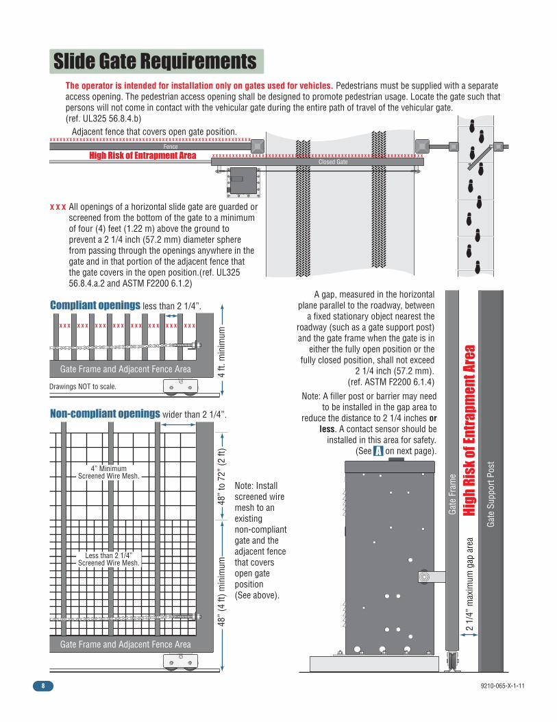
Note: A filler post or barrier may need to be installed in the gap area to
reduce the distance to 2 1/4 inches or less. A contact sensor should be
installed in this area for safety. (See on next page).
Slide Gate Requirements The operator is intended for installation only on gates used for vehicles. Pedestrians must be supplied with a separate access opening. The pedestrian access opening shall be designed to promote pedestrian usage. Locate the gate such that persons will not come in contact with the vehicular gate during the entire path of travel of the vehicular gate. (ref. UL325 56.8.4.b)
All openings of a horizontal slide gate are guarded or screened from the bottom of the gate to a minimum of four (4) feet (1.22 m) above the ground to prevent a 2 1/4 inch (57.2 mm) diameter sphere from passing through the openings anywhere in the gate and in that portion of the adjacent fence that the gate covers in the open position.(ref. UL325 56.8.4.a.2 and ASTM F2200 6.1.2)
Note: Install screened wire mesh to an existing non-compliant gate and the adjacent fence that covers open gate position (See above).
A gap, measured in the horizontal plane parallel to the roadway, between
a fixed stationary object nearest the roadway (such as a gate support post) and the gate frame when the gate is in
either the fully open position or the fully closed position, shall not exceed
2 1/4 inch (57.2 mm). (ref. ASTM F2200 6.1.4)
2 1/
4” m
axim
um g
ap a
rea
High
Ris
k of
Ent
rapm
ent A
rea
High Risk of Entrapment Area X X X X X X X X X X X X X X X X X X X X X X X X X X X X X X X X X X X X X X X X X X X X X X X X X X X X X X X X X X X X X X X X
X X X X X X X X X X X X X X X X X X X X X X X X X X X X X X X X X X X X X X X X X X X X X X X X X X X X X X X X X X X X X
X X X
X X XX X XX X XX X XX X XX X X X X XX X X
Adjacent fence that covers open gate position.
Drawings NOT to scale.
4 ft.
min
imum
Non-compliant openings wider than 2 1/4”.
Less than 2 1/4” Screened Wire Mesh.
4” Minimum Screened Wire Mesh.
Compliant openings less than 2 1/4”.
Gate
Sup
port
Post
Gate Frame and Adjacent Fence Area
Gate Frame and Adjacent Fence Area
A
Fence
Gate
Fra
me
Closed Gate
48”
(4 ft
) min
imum
48”
to 7
2” (2
ft)
9210-065-X-1-11 9
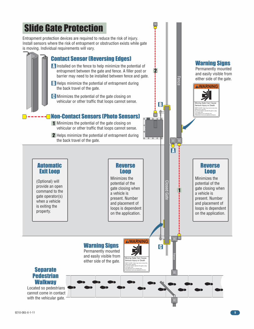
Slide Gate Protection
ReverseLoop
Automatic Exit Loop
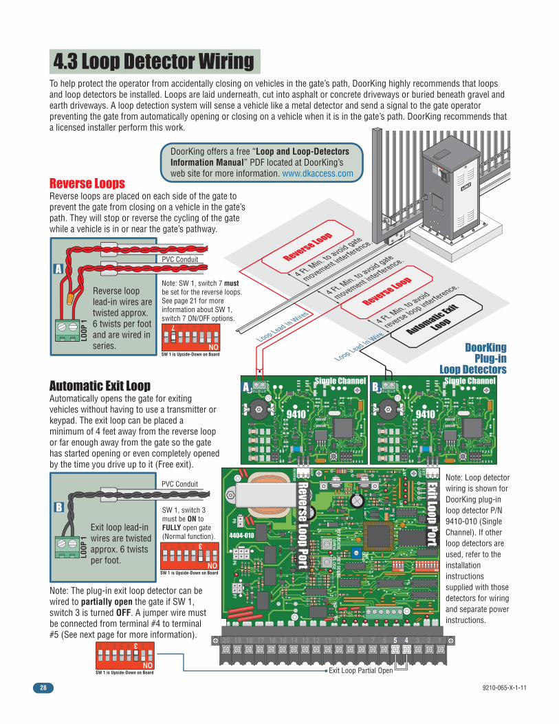
Minimizes the potential of the gate closing when a vehicle is present. Number and placement of loops is dependent on the application.
ReverseLoop
Minimizes the potential of the gate closing when a vehicle is present. Number and placement of loops is dependent on the application.
(Optional) will provide an open command to the gate operator(s) when a vehicle is exiting the property.
Warning SignsPermanently mounted and easily visible from either side of the gate.
Moving Gate Can CauseSerious Injury or DeathKEEP CLEAR! Gate may move at any timewithout prior warning.Do not let children operate the gate or playin the gate area.This entrance is for vehicles only.Pedestrians must use separate entrance.
Separate Pedestrian
Walkway Located so pedestrians cannot come in contact with the vehicular gate.
Non-Contact Sensors (Photo Sensors)
Contact Sensor (Reversing Edges)
1
2
A
Minimizes the potential of the gate closing on vehicular or other traffic that loops cannot sense.
Minimizes the potential of the gate closing on vehicular or other traffic that loops cannot sense.
Installed on the fence to help minimize the potential of entrapment between the gate and fence. A filler post or barrier may need to be installed between fence and gate.
B
C
Helps minimize the potential of entrapment during the back travel of the gate.
Helps minimize the potential of entrapment during the back travel of the gate.
Entrapment protection devices are required to reduce the risk of injury. Install sensors where the risk of entrapment or obstruction exists while gate is moving. Individual requirements will vary.
Fence
A
B
C
Closed Gate
Fence
Warning SignsPermanently mounted and easily visible from either side of the gate.
Moving Gate Can Cause Serious Injury or Death KEEP CLEAR! Gate may move at any time without prior warning. Do not let children operate the gate or play in the gate area. This entrance is for vehicles only. Pedestrians must use separate entrance.
2
1
9210-065-X-1-1110
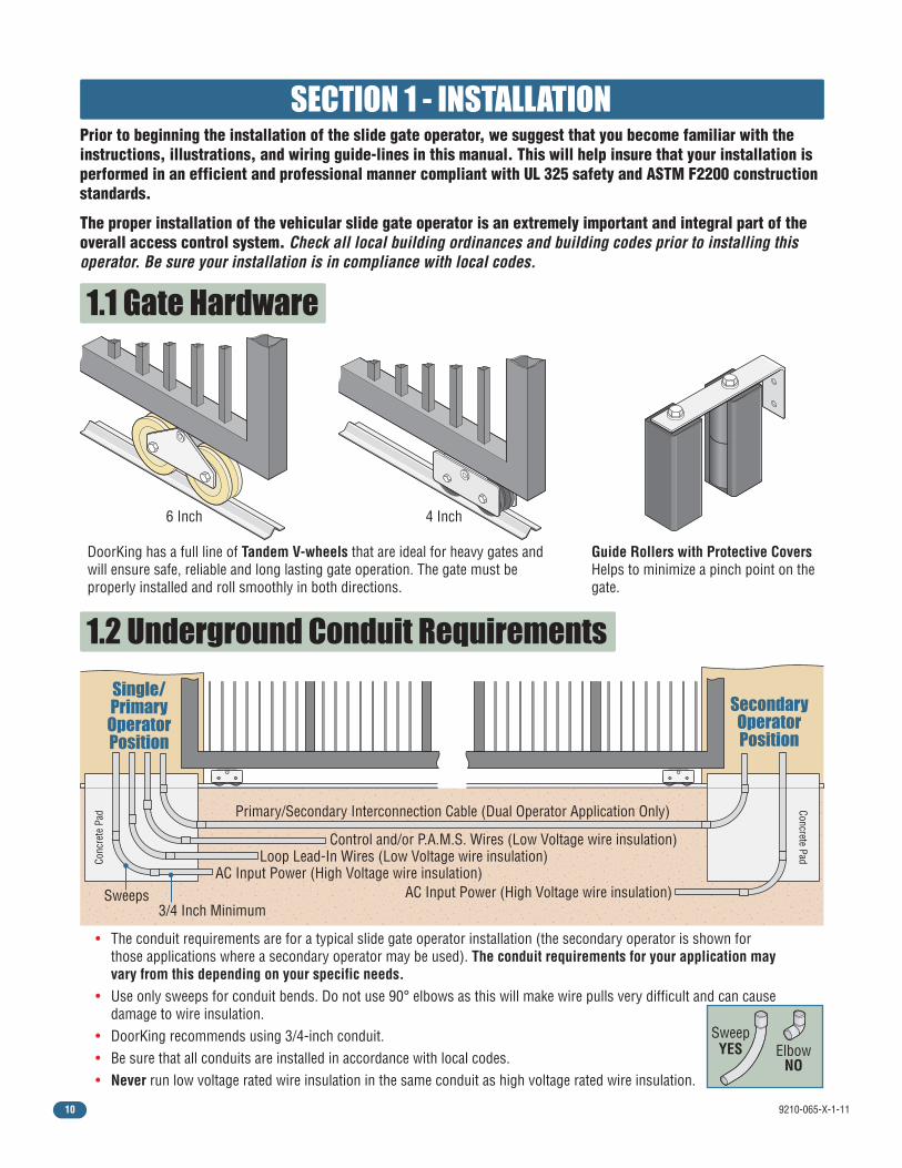
1.2 Underground Conduit Requirements
Primary/Secondary Interconnection Cable (Dual Operator Application Only)
Sweeps
Conc
rete
Pad
Concrete Pad
3/4 Inch Minimum
Single/Primary
OperatorPosition
Secondary Operator Position
SECTION 1 - INSTALLATION Prior to beginning the installation of the slide gate operator, we suggest that you become familiar with the instructions, illustrations, and wiring guide-lines in this manual. This will help insure that your installation is performed in an efficient and professional manner compliant with UL 325 safety and ASTM F2200 construction standards.
The proper installation of the vehicular slide gate operator is an extremely important and integral part of the overall access control system. Check all local building ordinances and building codes prior to installing this operator. Be sure your installation is in compliance with local codes.
1.1 Gate Hardware
DoorKing has a full line of Tandem V-wheels that are ideal for heavy gates and will ensure safe, reliable and long lasting gate operation. The gate must be properly installed and roll smoothly in both directions.
Guide Rollers with Protective Covers Helps to minimize a pinch point on the gate.
4 Inch6 Inch
• The conduit requirements are for a typical slide gate operator installation (the secondary operator is shown for those applications where a secondary operator may be used). The conduit requirements for your application may vary from this depending on your specific needs.• Use only sweeps for conduit bends. Do not use 90° elbows as this will make wire pulls very difficult and can cause damage to wire insulation.• DoorKing recommends using 3/4-inch conduit.• Be sure that all conduits are installed in accordance with local codes.• Never run low voltage rated wire insulation in the same conduit as high voltage rated wire insulation.
ElbowNO
SweepYES
Control and/or P.A.M.S. Wires (Low Voltage wire insulation)Loop Lead-In Wires (Low Voltage wire insulation)
AC Input Power (High Voltage wire insulation)AC Input Power (High Voltage wire insulation)

9210-065-X-1-11 11
1.3 Installation Options
#1 - Operator Mounted Directly on a Concrete Pad
#2 - Operator Mounted on the Heavy-Duty Pedestal Mounting Stand
Idler wheels are factory set in the correct position. Remove the chain knock-outs in operator housing.
The idler wheels must be moved to the lower position to use a chain tray. DO NOT remove the chain knock-outs.
The operator MUST be level. See the next page for typical gate types. We suggest that you contact the local building depart-ment to determine the required depth of the concrete pad since soil conditions and code requirements vary from city to city.
The pedestal mounting stand kit (P/N 9200-135) MUST be used when gates require a chain tray (Typically for gates that are longer than 20 feet in length). The chain tray helps support the weight of the chain and reduce the chain stretching that occurs over time. DoorKing offers a chain tray kit that will fit any length gate (P/N 2601-270 10 ft. connecting sections).DoorKing highly recommends using the pedestal stand for gates heavier than 2000 lbs. for a more secure attachment to a larger and heavier concrete pad. V-rail v-wheel gate type shown.
Typically used when gates are less than 20 feet in length and under 2000 lbs. in weight. V-rail v-wheel gate type shown.
WARNING
MOVING GATE CAN CAUSE
Operate gate only when gate area is in sight
and free of people and obstructions.
Do not allow children to play in gate area
or operate gate.
Do not stand in gate path or walk through
path while gate is moving.
Read owner’s manual and safety instructions.
SERIOUS INJURY OR DEATH
CLASS
CERTIFIED TO
CAN/CSA C22.2 NO. 247
CONFORMS TO
ANSI/UL-325
VEHICULAR GATE OPERATOR HP
53382
MODEL SERIAL VOLTS
PHASE
AMPS
60 Hz
MAX GATE LOAD DoorKing, Inc., Inglewood, CA
Idler Wheels
Idler Wheels
Chain Configuration
Chain Configuration
See page 13 for details.
See page16 fordetails.
See page16 fordetails.
See pages 14 and 15 for details.
Concrete Pad
Concrete Pad
WARNING
MOVING GATE CAN CAUSE
Operate gate only when gate area is in sight
and free of people and obstructions.
Do not allow children to play in gate area
or operate gate.
Do not stand in gate path or walk through
path while gate is moving.
Read owner’s manual and safety instructions.
SERIOUS INJURY OR DEATH
CLASS
CERTIFIED TO
CAN/CSA C22.2 NO. 247
CONFORMS TO
ANSI/UL-325
VEHICULAR GATE OPERATOR HP
53382
MODEL SERIAL VOLTS
PHASE
AMPS
60 Hz
MAX GATE LOAD DoorKing, Inc., Inglewood, CA
Pedestal
Mounting
StandChain Tra
y
9210-065-X-1-1112
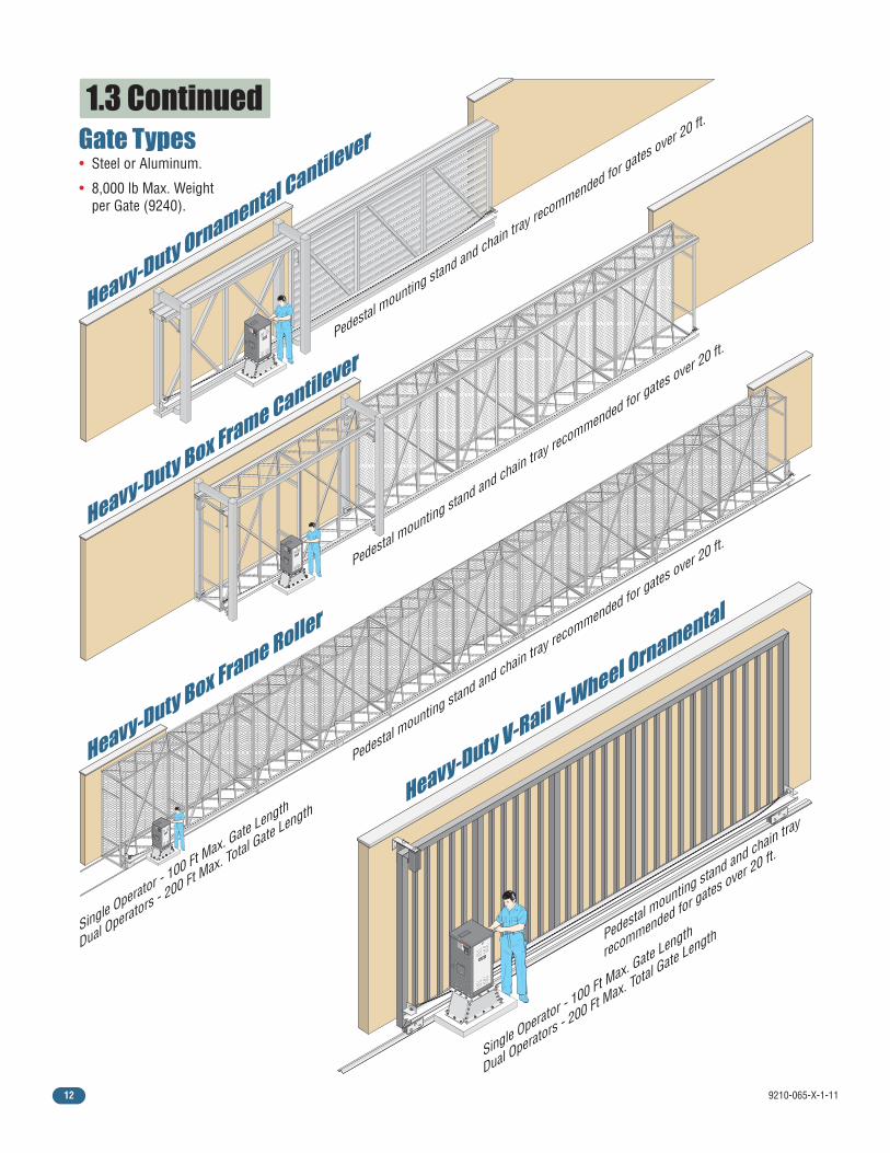
1.3 Continued
Pedestal mounting stand and chain tra
y recommended for gates over 20 ft.
Pedestal mounting stand and chain tra
y recommended for gates over 20 ft.
Pedestal mounting stand and chain tra
y recommended for gates over 20 ft.
Pedestal mounting stand and chain tra
y
recommended for gates over 20 ft.
Single Operator - 100 Ft M
ax. Gate Length
Dual Operators - 200 Ft M
ax. Total Gate Length
Single Operator - 100 Ft M
ax. Gate Length
Dual Operators - 200 Ft M
ax. Total Gate Length
Heavy-Duty Box Frame Roller
Heavy-Duty V-Rail V-Wheel Ornamental
Heavy-Duty Ornamental Cantilever
WARNING
MOVING GATE CAN CAUSE
Operate gate only when gate area is in sight
and free of people and obstructions.
Do not allow children to play in gate area
or operate gate.Do not stand in gate path or walk through
path while gate is moving.
Read owner’s manual and safety instructions.
SERIOUS INJURY OR DEATH
CLASS
CERTIFIED TO
CAN/CSA C22.2 NO. 247
CONFORMS TO
ANSI/UL-325
VEHICULAR GATE OPERATORHP
53382
MODELSERIALVOLTS
PHASE
AMPS
60 Hz
MAX GATE LOADDoorKing, Inc., Inglewood, CA
WARNING
MOVING GATE CAN CAUSE
Operate gate only when gate area is in sight
and free of people and obstructions.
Do not allow children to play in gate area
or operate gate.Do not stand in gate path or walk through
path while gate is moving.
Read owner’s manual and safety instructions.
SERIOUS INJURY OR DEATH
CLASS
CERTIFIED TO
CAN/CSA C22.2 NO. 247
CONFORMS TO
ANSI/UL-325
VEHICULAR GATE OPERATORHP
53382MODELSERIALVOLTS
PHASE
AMPS
60 Hz
MAX GATE LOADDoorKing, Inc., Inglewood, CA
Heavy-Duty Box Frame Cantilever
WARNING
MOVING GATE CAN CAUSE
Operate gate only when gate area is in sight
and free of people and obstructions.
Do not allow children to play in gate area
or operate gate.Do not stand in gate path or walk through
path while gate is moving.
Read owner’s manual and safety instructions.
SERIOUS INJURY OR DEATH
CLASS
CERTIFIED TO
CAN/CSA C22.2 NO. 247
CONFORMS TO
ANSI/UL-325VEHICULAR GATE OPERATOR
HP
53382MODELSERIALVOLTS
PHASE
AMPS
60 Hz
MAX GATE LOADDoorKing, Inc., Inglewood, CA
Gate Types
WARNING
MOVING GATE CAN CAUSE
Operate gate only when gate area is in sight
and free of people and obstructions.
Do not allow children to play in gate area
or operate gate.Do not stand in gate path or walk through
path while gate is moving.
Read owner’s manual and safety instructions.
SERIOUS INJURY OR DEATH
CLASS
CERTIFIED TO
CAN/CSA C22.2 NO. 247
CONFORMS TO
ANSI/UL-325
VEHICULAR GATE OPERATORHP
53382MODELSERIALVOLTS
PHASE
AMPS
60 Hz
MAX GATE LOADDoorKing, Inc., Inglewood, CA
• Steel or Aluminum.
• 8,000 lb Max. Weight per Gate (9240).
9210-065-X-1-11 13
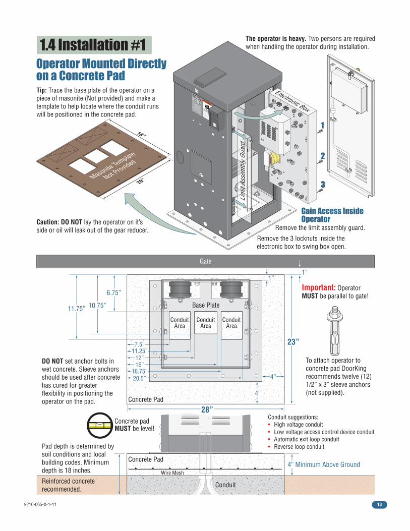
1.4 Installation #1
Remove the limit assembly guard.
Remove the 3 locknuts inside the electronic box to swing box open.
WARNING
MOVING GATE CAN CAUSE
Operate gate only when gate area is in sight
and free of people and obstructions.
Do not allow children to play in gate area
or operate gate.Do not stand in gate path or walk through
path while gate is moving.
Read owner’s manual and safety instructions.
SERIOUS INJURY OR DEATH
CLASS
CERTIFIED TO
CAN/CSA C22.2 NO. 247
CONFORMS TO
ANSI/UL-325
VEHICULAR GATE OPERATORHP
53382
MODELSERIALVOLTS
PHASE
AMPS
60 Hz
MAX GATE LOADDoorKing, Inc., Inglewood, CA
Lim
it As
sem
bly
Guar
d
Electronic Box
Tip: Trace the base plate of the operator on a piece of masonite (Not provided) and make a template to help locate where the conduit runs will be positioned in the concrete pad.
Caution: DO NOT lay the operator on it’s side or oil will leak out of the gear reducer.
The operator is heavy. Two persons are required when handling the operator during installation.
Pad depth is determined by soil conditions and local building codes. Minimum depth is 18 inches.
Reinforced concrete recommended.
DO NOT set anchor bolts in wet concrete. Sleeve anchors should be used after concrete has cured for greater flexibility in positioning the operator on the pad.
23”
6.75”
10.75”
7.5”
4”
4”
12”16”
16.75”
11.25”
20.5”
11.75”
4” Minimum Above Ground
28”Concrete Pad
Gain Access InsideOperator
Concrete Pad
Conduit
Conduit suggestions:• High voltage conduit• Low voltage access control device conduit• Automatic exit loop conduit• Reverse loop conduit
Base Plate
ConduitArea
ConduitArea
ConduitArea
Gate
1”
1
2
3
1”
Masonite Template
Not Provided
Important: Operator MUST be parallel to gate!
Concrete pad MUST be level!
1/2
To attach operator to concrete pad DoorKing recommends twelve (12) 1/2” x 3” sleeve anchors (not supplied).
Operator Mounted Directlyon a Concrete Pad
18”
20”
Wire Mesh
9210-065-X-1-1114
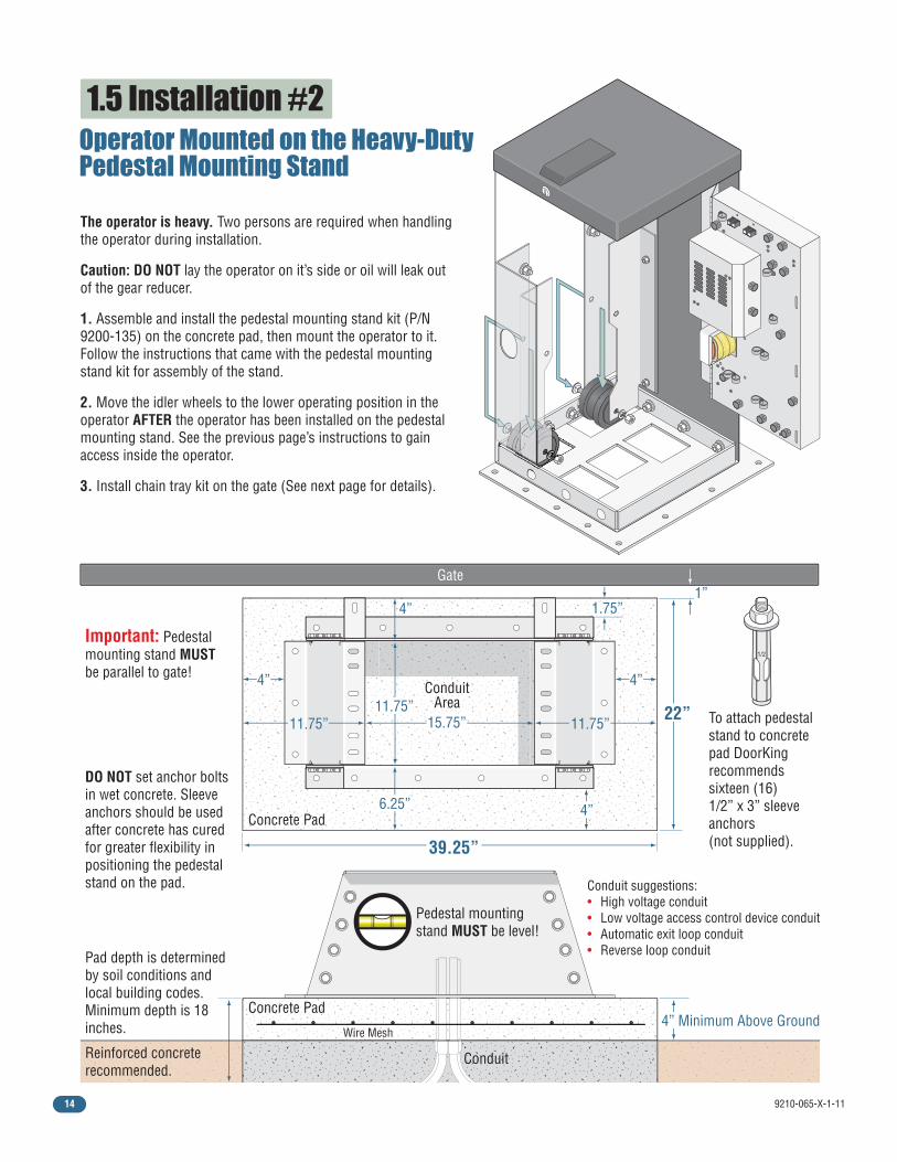
1.5 Installation #2
Pad depth is determined by soil conditions and local building codes. Minimum depth is 18 inches.
Reinforced concrete recommended.
DO NOT set anchor bolts in wet concrete. Sleeve anchors should be used after concrete has cured for greater flexibility in positioning the pedestal stand on the pad.
4” Minimum Above Ground
39.25”
Conduit
Conduit suggestions: • High voltage conduit • Low voltage access control device conduit • Automatic exit loop conduit • Reverse loop conduit
Gate 1”
The operator is heavy. Two persons are required when handling the operator during installation.
Caution: DO NOT lay the operator on it’s side or oil will leak out of the gear reducer.
1. Assemble and install the pedestal mounting stand kit (P/N 9200-135) on the concrete pad, then mount the operator to it. Follow the instructions that came with the pedestal mounting stand kit for assembly of the stand.
2. Move the idler wheels to the lower operating position in the operator AFTER the operator has been installed on the pedestal mounting stand. See the previous page’s instructions to gain access inside the operator.
3. Install chain tray kit on the gate (See next page for details).
22”
1.75”
11.75”
4”
11.75”
4” 4”
15.75” 11.75”
6.25” 4” Concrete Pad
Concrete Pad
Conduit Area
Important: Pedestal mounting stand MUST be parallel to gate!
Pedestal mounting stand MUST be level!
1/2
To attach pedestal stand to concrete pad DoorKing recommends sixteen (16) 1/2” x 3” sleeve anchors (not supplied).
Operator Mounted on the Heavy-DutyPedestal Mounting Stand
Wire Mesh
9210-065-X-1-11 15
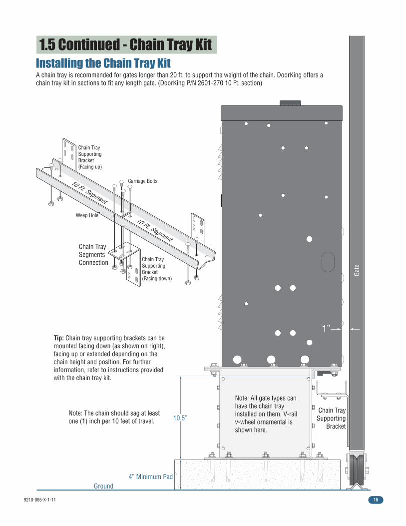
1.5 Continued - Chain Tray Kit
Tip: Chain tray supporting brackets can be mounted facing down (as shown on right), facing up or extended depending on the chain height and position. For further information, refer to instructions provided with the chain tray kit.
Chain TraySupporting
Bracket
A chain tray is recommended for gates longer than 20 ft. to support the weight of the chain. DoorKing offers a chain tray kit in sections to fit any length gate. (DoorKing P/N 2601-270 10 Ft. section)
Chain TraySupportingBracket(Facing down)
Chain TraySupportingBracket(Facing up)
Weep Hole
Carriage Bolts
Gate
Note: The chain should sag at least one (1) inch per 10 feet of travel.
Note: All gate types can have the chain tray installed on them, V-rail v-wheel ornamental is shown here.
1”
10 Ft. Segment
Chain TraySegmentsConnection
10 Ft. Segment
Installing the Chain Tray Kit
10.5”
4” Minimum PadGround
9210-065-X-1-1116
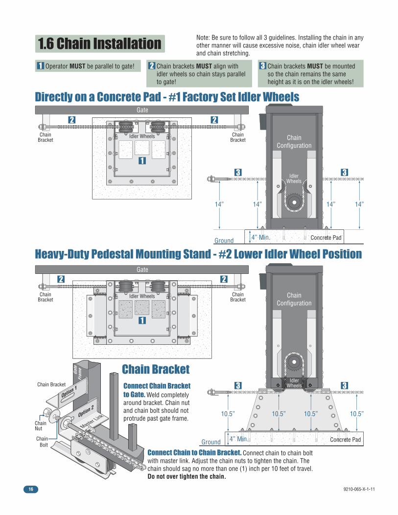
1.6 Chain Installation
Directly on a Concrete Pad - #1 Factory Set Idler Wheels
Heavy-Duty Pedestal Mounting Stand - #2 Lower Idler Wheel Position
Chain Bracket
IdlerWheels
IdlerWheels
Note: Be sure to follow all 3 guidelines. Installing the chain in any other manner will cause excessive noise, chain idler wheel wear and chain stretching.
10.5”
14”14” 14” 14”
10.5” 10.5” 10.5”
Gate
Gate
Operator MUST be parallel to gate! Chain brackets MUST align with idler wheels so chain stays parallel to gate!
Chain brackets MUST be mounted so the chain remains the same height as it is on the idler wheels!
1
1
1
2
2 2
2 2
3
3 3
3 3
ChainBracket
ChainBracket
ChainBracket
ChainBracket
Idler Wheels
Idler Wheels
ChainConfiguration
ChainConfiguration
Connect Chain Bracketto Gate. Weld completely around bracket. Chain nut and chain bolt should not protrude past gate frame.
Connect Chain to Chain Bracket. Connect chain to chain bolt with master link. Adjust the chain nuts to tighten the chain. The chain should sag no more than one (1) inch per 10 feet of travel. Do not over tighten the chain.
ChainNut
ChainBolt
Chain Bracket
Option 2
Master Link
Option 1
Gate
Fram
e
Concrete Pad4” Min.Ground
Ground Concrete Pad4” Min.
9210-065-X-1-11 17
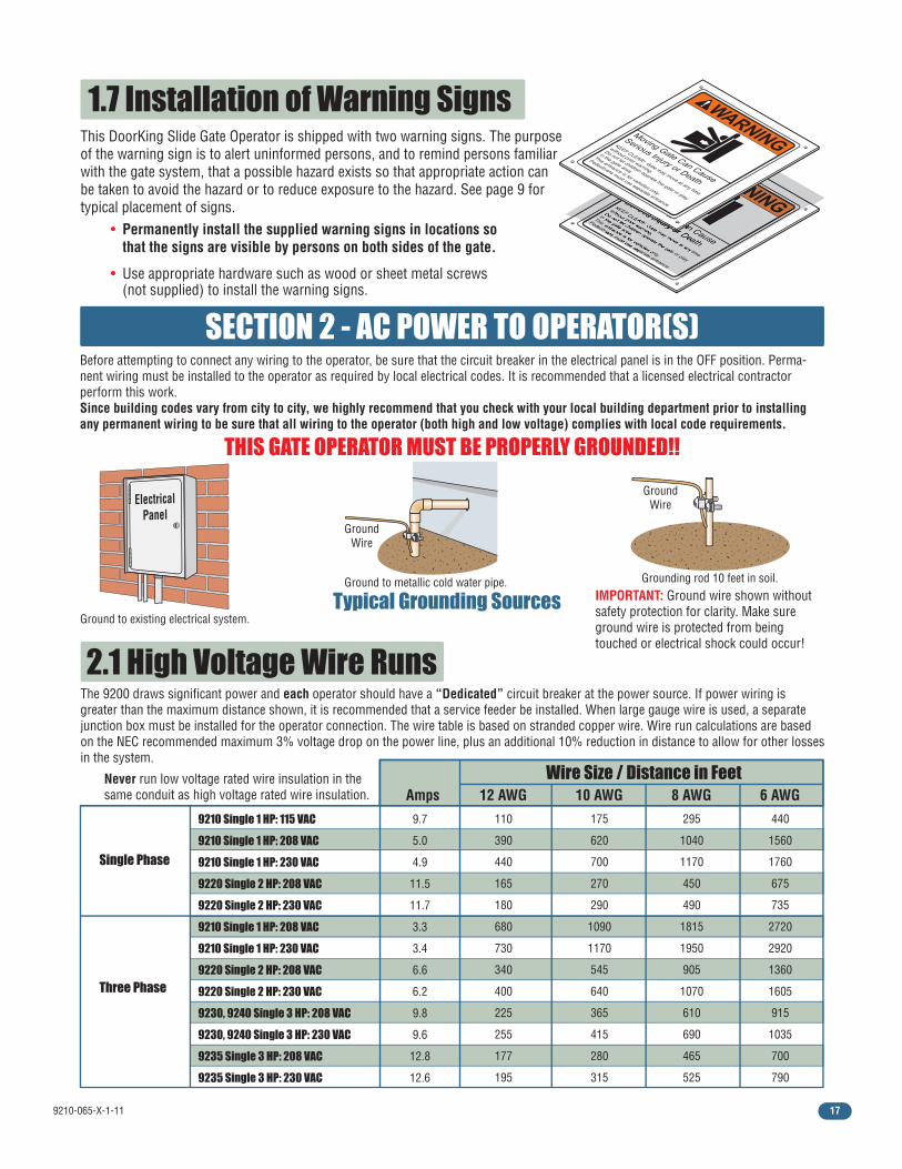
1.7 Installation of Warning SignsThis DoorKing Slide Gate Operator is shipped with two warning signs. The purpose of the warning sign is to alert uninformed persons, and to remind persons familiar with the gate system, that a possible hazard exists so that appropriate action can be taken to avoid the hazard or to reduce exposure to the hazard. See page 9 for typical placement of signs.
• Permanently install the supplied warning signs in locations so that the signs are visible by persons on both sides of the gate.
• Use appropriate hardware such as wood or sheet metal screws (not supplied) to install the warning signs.
2.1 High Voltage Wire RunsThe 9200 draws significant power and each operator should have a “Dedicated” circuit breaker at the power source. If power wiring is greater than the maximum distance shown, it is recommended that a service feeder be installed. When large gauge wire is used, a separate junction box must be installed for the operator connection. The wire table is based on stranded copper wire. Wire run calculations are based on the NEC recommended maximum 3% voltage drop on the power line, plus an additional 10% reduction in distance to allow for other losses in the system.
Wire Size / Distance in FeetAmps 12 AWG 10 AWG 8 AWG 6 AWG
9210 Single 1 HP: 115 VAC
9210 Single 1 HP: 208 VAC
9210 Single 1 HP: 230 VAC
9220 Single 2 HP: 208 VAC
9220 Single 2 HP: 230 VAC
9210 Single 1 HP: 208 VAC
9210 Single 1 HP: 230 VAC
9220 Single 2 HP: 208 VAC
9220 Single 2 HP: 230 VAC
9230, 9240 Single 3 HP: 208 VAC
9230, 9240 Single 3 HP: 230 VAC
9235 Single 3 HP: 208 VAC
9235 Single 3 HP: 230 VAC
Single Phase
Three Phase
SECTION 2 - AC POWER TO OPERATOR(S)Before attempting to connect any wiring to the operator, be sure that the circuit breaker in the electrical panel is in the OFF position. Perma-nent wiring must be installed to the operator as required by local electrical codes. It is recommended that a licensed electrical contractor perform this work. Since building codes vary from city to city, we highly recommend that you check with your local building department prior to installing any permanent wiring to be sure that all wiring to the operator (both high and low voltage) complies with local code requirements.
THIS GATE OPERATOR MUST BE PROPERLY GROUNDED!!
110
390
440
165
180
680
730
340
400
225
255
177
195
175
620
700
270
290
1090
1170
545
640
365
415
280
315
295
1040
1170
450
490
1815
1950
905
1070
610
690
465
525
440
1560
1760
675
735
2720
2920
1360
1605
915
1035
700
790
9.7
5.0
4.9
11.5
11.7
3.3
3.4
6.6
6.2
9.8
9.6
12.8
12.6
Never run low voltage rated wire insulation in thesame conduit as high voltage rated wire insulation.
Typical Grounding SourcesGround to metallic cold water pipe.
GroundWire
GroundWire
Ground to existing electrical system.
ElectricalPanel
Grounding rod 10 feet in soil.IMPORTANT: Ground wire shown without safety protection for clarity. Make sure ground wire is protected from being touched or electrical shock could occur!
9210-065-X-1-1118
1
2
3
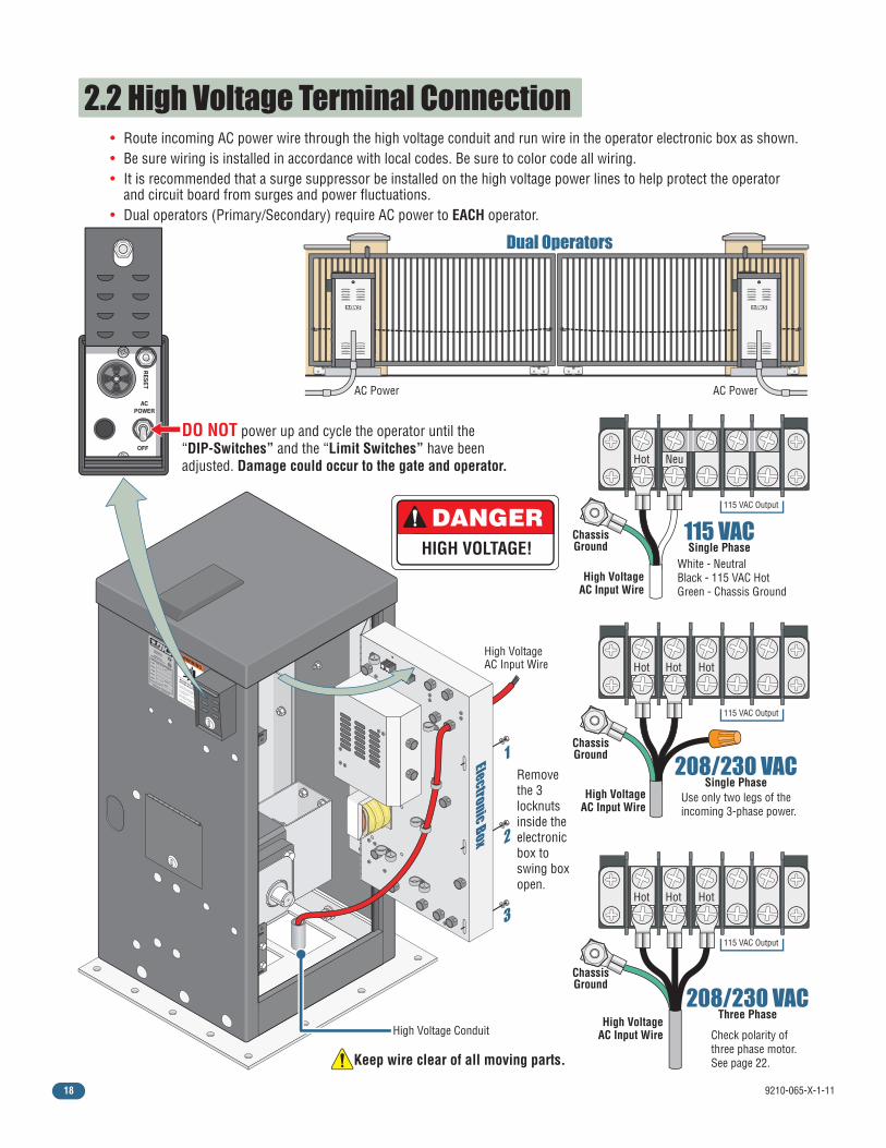
2.2 High Voltage Terminal Connection• Route incoming AC power wire through the high voltage conduit and run wire in the operator electronic box as shown.• Be sure wiring is installed in accordance with local codes. Be sure to color code all wiring.• It is recommended that a surge suppressor be installed on the high voltage power lines to help protect the operator and circuit board from surges and power fluctuations. • Dual operators (Primary/Secondary) require AC power to EACH operator.
DANGERHIGH VOLTAGE!
WARNING
MOVING GATE CAN CAUSE
Operate gate only when gate area is in sight
and free of people and obstructions.
Do not allow children to play in gate area
or operate gate.Do not stand in gate path or walk through
path while gate is moving.
Read owner’s manual and safety instructions.
SERIOUS INJURY OR DEATH
CLASS
CERTIFIED TO
CAN/CSA C22.2 NO. 247
CONFORMS TO
ANSI/UL-325
VEHICULAR GATE OPERATORHP
53382
MODELSERIALVOLTS
PHASE
AMPS
60 Hz
MAX GATE LOADDoorKing, Inc., Inglewood, CA
208/230 VACThree Phase
ChassisGround
High VoltageAC Input Wire
Hot
115 VAC Output
Hot Hot
ChassisGround
High VoltageAC Input Wire
Hot
115 VAC Output
Neu
115 VACSingle Phase
White - NeutralBlack - 115 VAC HotGreen - Chassis Ground
High Voltage Conduit
High VoltageAC Input Wire
Keep wire clear of all moving parts.
DO NOT power up and cycle the operator until the “DIP-Switches” and the “Limit Switches” have been adjusted. Damage could occur to the gate and operator.
ACPOWER
OFF
RE
SE
T
AC Power AC Power
Dual Operators
208/230 VACSingle Phase
ChassisGround
High VoltageAC Input Wire
Hot
115 VAC Output
Hot Hot
Use only two legs of the incoming 3-phase power.
Remove the 3 locknuts inside the electronic box to swing box open.
Check polarity of three phase motor. See page 22.
Electronic Box
9210-065-X-1-11 19
TIME
DELAY
EXIT LO
OP
LMT
LMT
REVERSE
LOO
P
REV SENSE O
PEN REV SENSE CLO
SE
1
ON
2 3 4 1
ON
2 3 4 5 6 7 8
NC NO
P8 P7
P6
4404-010
20 19 18 17 16 15 14 13 12 11 10 9 8 7 6 5 4 3 2 1
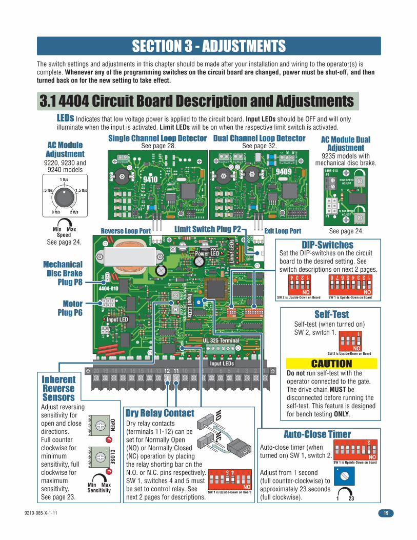
3.1 4404 Circuit Board Description and Adjustments
SECTION 3 - ADJUSTMENTS The switch settings and adjustments in this chapter should be made after your installation and wiring to the operator(s) is complete. Whenever any of the programming switches on the circuit board are changed, power must be shut-off, and then turned back on for the new setting to take effect.
Auto-close timer (when turned on) SW 1, switch 2.
Dry relay contacts (terminals 11-12) can be set for Normally Open (NO) or Normally Closed (NC) operation by placing the relay shorting bar on the N.O. or N.C. pins respectively. SW 1, switches 4 and 5 must be set to control relay. See next 2 pages for descriptions.
Auto-Close Timer
AC ModuleAdjustment
9220, 9230 and9240 models
Dual Channel Loop DetectorSingle Channel Loop Detector
Dry Relay Contact
Set the DIP-switches on the circuit board to the desired setting. See switch descriptions on next 2 pages.
DIP-Switches
LEDs Indicates that low voltage power is applied to the circuit board. Input LEDs should be OFF and will only illuminate when the input is activated. Limit LEDs will be on when the respective limit switch is activated.
Adjust reversing sensitivity for open and close directions.Full counter clockwise for minimum sensitivity, full clockwise for maximum sensitivity.See page 23.
InherentReverseSensors
MotorPlug P6
MechanicalDisc Brake
Plug P8
Limit Switch Plug P2
Self-test (when turned on) SW 2, switch 1.
CAUTION Do not run self-test with the operator connected to the gate. The drive chain MUST be disconnected before running the self-test. This feature is designed for bench testing ONLY.
Self-Test
UL 325 Terminal
Power LED
Exit Loop PortReverse Loop Port
LMT L
imit
LEDs
Input LEDs
Input LED
Input LEDs
94109409
1 23
Adjust from 1 second (full counter-clockwise) to approximately 23 seconds (full clockwise).
NC NO
Min Max
CLOSE
Sensitivity
OPEN
1 ft/s
.5 ft/s
0 ft/s 2 ft/s
1.5 ft/s
Min MaxSpeed
See page 24.
See page 24.
See page 32.See page 28.AC Module Dual
Adjustment9235 models with
mechanical disc brake.
HIGH SPEED ADJUST
SLOW SPEED ADJUST P1
P2 1495-010
1
ON
2345678
SW 1 is Upside-Down on Board
1
ON
234
SW 2 is Upside-Down on Board
1
ON
234
SW 2 is Upside-Down on Board
1
ON
2345678
SW 1 is Upside-Down on Board
1
ON
2345678
SW 1 is Upside-Down on Board
9210-065-X-1-1120
1
ON
23456781
ON
234
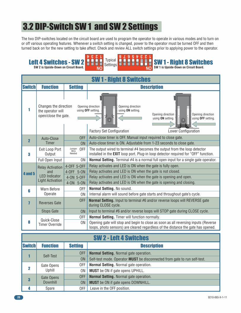
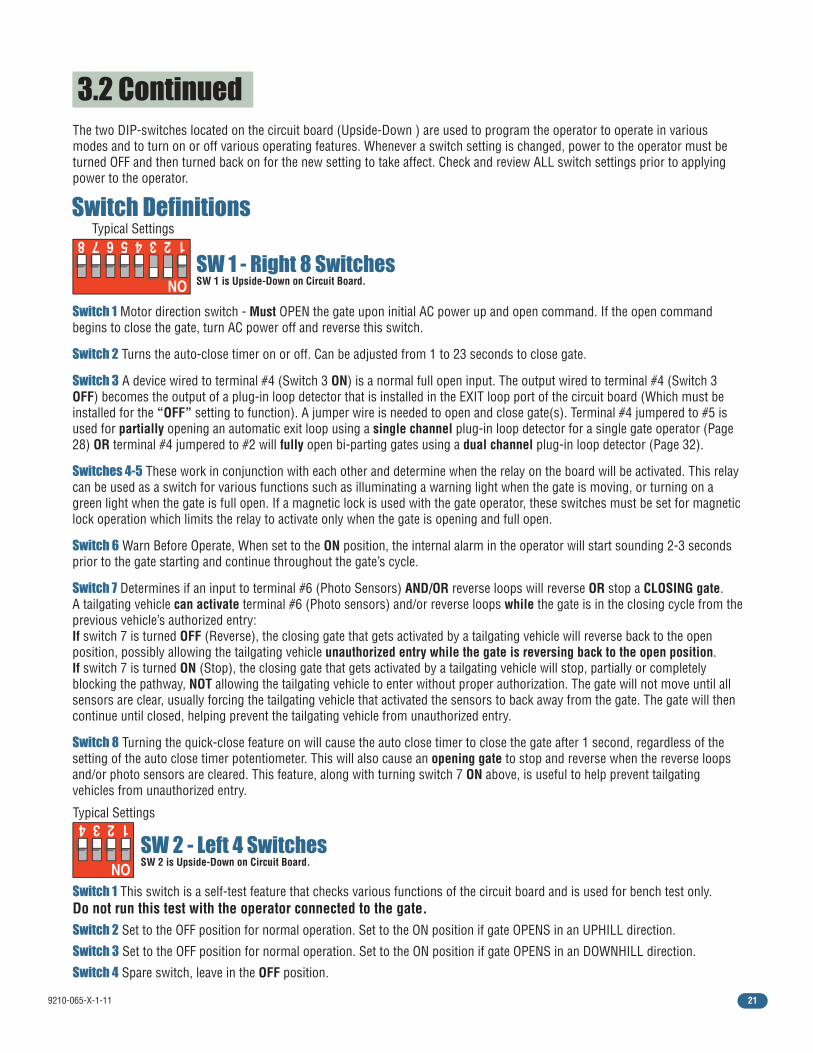
3.2 DIP-Switch SW 1 and SW 2 Settings The two DIP-switches located on the circuit board are used to program the operator to operate in various modes and to turn on or off various operating features. Whenever a switch setting is changed, power to the operator must be turned OFF and then turned back on for the new setting to take affect. Check and review ALL switch settings prior to applying power to the operator.
Switch Function Setting Description
SW 2 - Left 4 Switches
2
Spare4
Exit Loop PortOutput
TypicalSettings
Full Open Input
Factory Set Configuration Lower Configuration
Warn BeforeOperate
1
The output wired to terminal #4 becomes the output from the loop detector installed in the EXIT loop port. Plug-in loop detector required for “OFF” function. Normal Setting. Terminal #4 is a normal full open input for a single gate operator.
Reverses Gate
Stops Gate
Switch Function Setting Description
SW 1 - Right 8 Switches
OFFON
4-OFF4-OFF4-ON4-ON
5-OFF5-ON
5-OFF5-ON
Auto-CloseTimer
Relay Activationand
LED IndicatorLight Activation
2
1
3
4 and 5
7
8
OFFON
OFF
ON
Normal Setting. No sound.Internal alarm will sound before gate starts and throughout gate’s cycle.
Auto-close timer is OFF. Manual input required to close gate.Auto-close timer is ON. Adjustable from 1-23 seconds to close gate.
Self-Test
Gate OpensUphill
3Gate Opens
Downhill
6
Relay activates and LED is ON when the gate is fully open. Relay activates and LED is ON when the gate is not closed.Relay activates and LED is ON when the gate is opening and open. Relay activates and LED is ON when the gate is opening and closing.
Changes the direction the operator will open/close the gate. Opening direction
using ON setting.Opening directionusing OFF setting.
Opening directionusing ON setting.
Opening directionusing OFF setting.
OFFON
Normal Setting. Timer will function normally.Opening gate will stop and begin to close as soon as all reversing inputs (Reverse loops, photo sensors) are cleared regardless of the distance the gate has opened.
OFFON
Normal Setting. Normal gate operation.Self-test mode. Operator MUST be disconnected from gate to run self-test.
OFFON
Normal Setting. Normal gate operation.MUST be ON if gate opens UPHILL.
OFFON
Normal Setting. Normal gate operation.MUST be ON if gate opens DOWNHILL.
OFF Leave in the OFF position.
Left 4 Switches - SW 2SW 2 is Upside-Down on Circuit Board.
SW 1 - Right 8 SwitchesSW 1 is Upside-Down on Circuit Board.
OFF
ON
Normal Setting. Input to terminal #6 and/or reverse loops will REVERSE gate during CLOSE cycle.Input to terminal #6 and/or reverse loops will STOP gate during CLOSE cycle.
Quick-CloseTimer Override
JumperWire
Needed
9210-065-X-1-11 21
3.2 Continued
Switch 1 This switch is a self-test feature that checks various functions of the circuit board and is used for bench test only. Do not run this test with the operator connected to the gate.Switch 2 Set to the OFF position for normal operation. Set to the ON position if gate OPENS in an UPHILL direction.
Switch 3 Set to the OFF position for normal operation. Set to the ON position if gate OPENS in an DOWNHILL direction.
Switch 4 Spare switch, leave in the OFF position.
SW 2 - Left 4 SwitchesSW 2 is Upside-Down on Circuit Board.
SW 1 - Right 8 SwitchesSW 1 is Upside-Down on Circuit Board.
The two DIP-switches located on the circuit board (Upside-Down ) are used to program the operator to operate in various modes and to turn on or off various operating features. Whenever a switch setting is changed, power to the operator must be turned OFF and then turned back on for the new setting to take affect. Check and review ALL switch settings prior to applying power to the operator.
Switch Definitions
1
ON
2345678
1
ON
234Typical Settings
Typical Settings
Switch 1 Motor direction switch - Must OPEN the gate upon initial AC power up and open command. If the open command begins to close the gate, turn AC power off and reverse this switch.
Switch 2 Turns the auto-close timer on or off. Can be adjusted from 1 to 23 seconds to close gate.
Switch 3 A device wired to terminal #4 (Switch 3 ON) is a normal full open input. The output wired to terminal #4 (Switch 3 OFF) becomes the output of a plug-in loop detector that is installed in the EXIT loop port of the circuit board (Which must be installed for the “OFF” setting to function). A jumper wire is needed to open and close gate(s). Terminal #4 jumpered to #5 is used for partially opening an automatic exit loop using a single channel plug-in loop detector for a single gate operator (Page 28) OR terminal #4 jumpered to #2 will fully open bi-parting gates using a dual channel plug-in loop detector (Page 32).
Switches 4-5 These work in conjunction with each other and determine when the relay on the board will be activated. This relay can be used as a switch for various functions such as illuminating a warning light when the gate is moving, or turning on a green light when the gate is full open. If a magnetic lock is used with the gate operator, these switches must be set for magnetic lock operation which limits the relay to activate only when the gate is opening and full open.
Switch 6 Warn Before Operate, When set to the ON position, the internal alarm in the operator will start sounding 2-3 seconds prior to the gate starting and continue throughout the gate’s cycle.
Switch 7 Determines if an input to terminal #6 (Photo Sensors) AND/OR reverse loops will reverse OR stop a CLOSING gate.A tailgating vehicle can activate terminal #6 (Photo sensors) and/or reverse loops while the gate is in the closing cycle from the previous vehicle’s authorized entry:If switch 7 is turned OFF (Reverse), the closing gate that gets activated by a tailgating vehicle will reverse back to the open position, possibly allowing the tailgating vehicle unauthorized entry while the gate is reversing back to the open position.If switch 7 is turned ON (Stop), the closing gate that gets activated by a tailgating vehicle will stop, partially or completely blocking the pathway, NOT allowing the tailgating vehicle to enter without proper authorization. The gate will not move until all sensors are clear, usually forcing the tailgating vehicle that activated the sensors to back away from the gate. The gate will then continue until closed, helping prevent the tailgating vehicle from unauthorized entry.
Switch 8 Turning the quick-close feature on will cause the auto close timer to close the gate after 1 second, regardless of the setting of the auto close timer potentiometer. This will also cause an opening gate to stop and reverse when the reverse loops and/or photo sensors are cleared. This feature, along with turning switch 7 ON above, is useful to help prevent tailgating vehicles from unauthorized entry.
9210-065-X-1-1122
TIME
DELAY
EXITLO
OP
LMT
LMT
REVERSE
LOO
P
REV SENSEO
PENREV SENSECLO
SE
1
ON
234 1
ON
2345678
NCNO
P8P7
P6
4404-010
20 19 18 17 16 15 14 13 12 11 10 9 8 7 6 5 4 3 2 1
Limit Nut
AA1
C1B
C
Limit LEDs
CL CCCC
AAAAAAAAAAA
MTTTTTTTTT
LLLLT
LLLLLT
LLLLLLT
LLLLLLLT
LLLLLLMTT
LLLLLMTT
LLLMTT
LLMTT
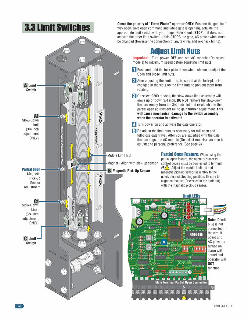
Note: If limit plug is not connected to the circuit board and AC power is turned on, alarm will sound and operator will NOT function.
Main Terminal Partial Open Connection
PushPush
Lock-Plate
Limit Nut
A
B
C
A
CCCC
Slow-Dow
n Limit
Slow-Dow
n Limit
A1
C1
Partial Open Adjustment Rail
3.3 Limit Switches
Adjust Limit NutsImportant: Turn power OFF and set AC module (On select models) to maximum speed before adjusting limit nuts!
Limit Nut
Push and hold the lock plate down where shown to adjust the Open and Close limit nuts.
After adjusting the limit nuts, be sure that the lock-plate is engaged in the slots on the limit nuts to prevent them from rotating.
On select 9200 models, the slow-down limit assembly will move up or down 3/4 inch. DO NOT remove the slow-down limit assembly from the 3/4 inch slot and re-attach it in the partial open adjustment rail to gain further adjustment. This will cause mechanical damage to the switch assembly when the operator is activated.
Turn power on and activate the gate operator.
Re-adjust the limit nuts as necessary for full-open and full-close gate travel. After you are satisified with the gate limit settings, the AC module (On select models) can then be adjusted to personal preference (See page 24).
1
2
45
3
Partial Open Feature: When using the partial open feature, the operator’s access control device must be connected to terminal #5 . Adjust the middle limit nut and magnetic pick-up sensor assembly to the gate’s desired stopping position. Be sure to align the magnet (Recessed in the limit nut) with the magnetic pick-up sensor.
Slow-DownLimit
(3/4 inchadjustment
ONLY)
Slow-DownLimit
(3/4 inchadjustment
ONLY)
Partial OpenMagnetic
Pick-upSensor
Adjustment
LimitSwitch
LimitSwitch
A
C
A1
C1
Middle Limit Nut
Magnet - Align with pick-up sensor
Magnetic Pick-Up SensorB
Check the polarity of “Three Phase” operator ONLY: Position the gate half way open. Give open command and while gate is opening, activate the appropriate limit switch with your finger. Gate should STOP. If it does not, activate the other limit switch. If this STOPS the gate, AC power wires must be changed (Reverse the connection of any 2 wires and re-check limits).
9210-065-X-1-11 23
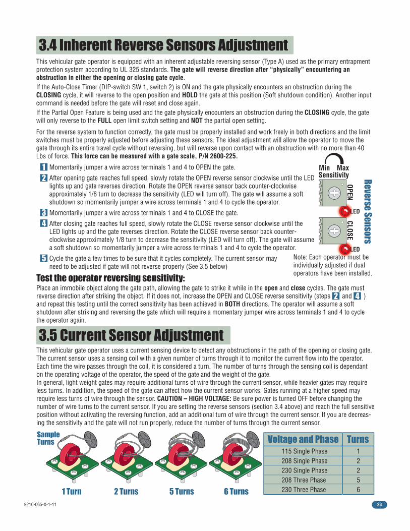
3.4 Inherent Reverse Sensors Adjustment
Test the operator reversing sensitivity:
Momentarily jumper a wire across terminals 1 and 4 to OPEN the gate.
After opening gate reaches full speed, slowly rotate the OPEN reverse sensor clockwise until the LED lights up and gate reverses direction. Rotate the OPEN reverse sensor back counter-clockwise approximately 1/8 turn to decrease the sensitivity (LED will turn off). The gate will assume a soft shutdown so momentarily jumper a wire across terminals 1 and 4 to cycle the operator.
Momentarily jumper a wire across terminals 1 and 4 to CLOSE the gate.
After closing gate reaches full speed, slowly rotate the CLOSE reverse sensor clockwise until the LED lights up and the gate reverses direction. Rotate the CLOSE reverse sensor back counter-clockwise approximately 1/8 turn to decrease the sensitivity (LED will turn off). The gate will assume a soft shutdown so momentarily jumper a wire across terminals 1 and 4 to cycle the operator.
Cycle the gate a few times to be sure that it cycles completely. The current sensor mayneed to be adjusted if gate will not reverse properly (See 3.5 below)
12
Place an immobile object along the gate path, allowing the gate to strike it while in the open and close cycles. The gate must reverse direction after striking the object. If it does not, increase the OPEN and CLOSE reverse sensitivity (steps and ) and repeat this testing until the correct sensitivity has been achieved in BOTH directions. The operator will assume a soft shutdown after striking and reversing the gate which will require a momentary jumper wire across terminals 1 and 4 to cycle the operator again.
2 4
34
5
3.5 Current Sensor AdjustmentThis vehicular gate operator uses a current sensing device to detect any obstructions in the path of the opening or closing gate. The current sensor uses a sensing coil with a given number of turns through it to monitor the current flow into the operator. Each time the wire passes through the coil, it is considered a turn. The number of turns through the sensing coil is dependant on the operating voltage of the operator, the speed of the gate and the weight of the gate. In general, light weight gates may require additional turns of wire through the current sensor, while heavier gates may require less turns. In addition, the speed of the gate can affect how the current sensor works. Gates running at a higher speed may require less turns of wire through the sensor. CAUTION – HIGH VOLTAGE: Be sure power is turned OFF before changing the number of wire turns to the current sensor. If you are setting the reverse sensors (section 3.4 above) and reach the full sensitive position without activating the reversing function, add an additional turn of wire through the current sensor. If you are decreas-ing the sensitivity and the gate will not run properly, reduce the number of turns through the current sensor.
Reverse Sensors
Note: Each operator must be individually adjusted if dual operators have been installed.
Min Max
CLOSE
Sensitivity
OPEN
Voltage and Phase Turns115 Single Phase 208 Single Phase 230 Single Phase 208 Three Phase 230 Three Phase
1 2 2 5 6
This vehicular gate operator is equipped with an inherent adjustable reversing sensor (Type A) used as the primary entrapment protection system according to UL 325 standards. The gate will reverse direction after “physically” encountering an obstruction in either the opening or closing gate cycle.If the Auto-Close Timer (DIP-switch SW 1, switch 2) is ON and the gate physically encounters an obstruction during the CLOSING cycle, it will reverse to the open position and HOLD the gate at this position (Soft shutdown condition). Another input command is needed before the gate will reset and close again.If the Partial Open Feature is being used and the gate physically encounters an obstruction during the CLOSING cycle, the gate will only reverse to the FULL open limit switch setting and NOT the partial open setting.
For the reverse system to function correctly, the gate must be properly installed and work freely in both directions and the limit switches must be properly adjusted before adjusting these sensors. The ideal adjustment will allow the operator to move the gate through its entire travel cycle without reversing, but will reverse upon contact with an obstruction with no more than 40 Lbs of force. This force can be measured with a gate scale, P/N 2600-225.
LED
LED
1 Turn 2 Turns 5 Turns 6 Turns
SampleTurns
1 2 5 6
9210-065-X-1-1124
1 2 5 6 11 12 2 14 13A
13B
13C
15 25 2 30 31 TXA
TXB
U
L1 L2 L3
VT2
W B- B+
Mode
EPM
T1 T3
2. 0
SCF seriesbasic I/O control
1 2 5 6 11 13A
13B
13E
25 16 17
U
L1 L2 L3 B- B+
V W PE PE
Mode
EPM 1. 0
SCM seriesbasic I/O control
1 ft/s
.5 ft/s
0 ft/s 2 ft/s
1.5 ft/s
Min MaxSpeed
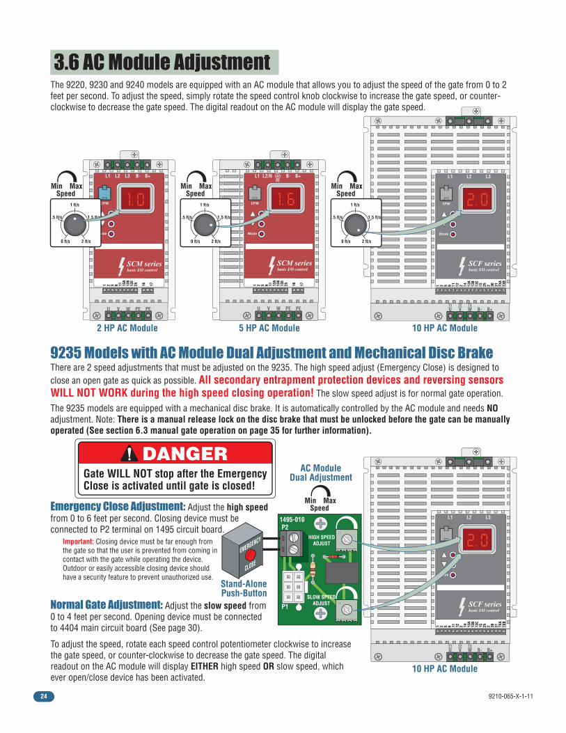
3.6 AC Module AdjustmentThe 9220, 9230 and 9240 models are equipped with an AC module that allows you to adjust the speed of the gate from 0 to 2 feet per second. To adjust the speed, simply rotate the speed control knob clockwise to increase the gate speed, or counter-clockwise to decrease the gate speed. The digital readout on the AC module will display the gate speed.
There are 2 speed adjustments that must be adjusted on the 9235. The high speed adjust (Emergency Close) is designed to close an open gate as quick as possible. All secondary entrapment protection devices and reversing sensors WILL NOT WORK during the high speed closing operation! The slow speed adjust is for normal gate operation.
The 9235 models are equipped with a mechanical disc brake. It is automatically controlled by the AC module and needs NO adjustment. Note: There is a manual release lock on the disc brake that must be unlocked before the gate can be manually operated (See section 6.3 manual gate operation on page 35 for further information).
9235 Models with AC Module Dual Adjustment and Mechanical Disc Brake
HIGH SPEEDADJUST
SLOW SPEEDADJUSTP1
P21495-010
Min MaxSpeedEmergency Close Adjustment: Adjust the high speed
from 0 to 6 feet per second. Closing device must be connected to P2 terminal on 1495 circuit board.
Normal Gate Adjustment: Adjust the slow speed from 0 to 4 feet per second. Opening device must be connected to 4404 main circuit board (See page 30).
To adjust the speed, rotate each speed control potentiometer clockwise to increase the gate speed, or counter-clockwise to decrease the gate speed. The digital readout on the AC module will display EITHER high speed OR slow speed, which ever open/close device has been activated.
DANGERGate WILL NOT stop after the EmergencyClose is activated until gate is closed!
Stand-AlonePush-Button
2 HP AC Module 5 HP AC Module 10 HP AC Module
Important: Closing device must be far enough from the gate so that the user is prevented from coming in contact with the gate while operating the device. Outdoor or easily accessible closing device should have a security feature to prevent unauthorized use.
EMERGENCY
CLOSE
1 2 5 6 11 13A
13B
13E
25 16 17
U
L1 L2/N B- B+
V W PE PE
Mode
EPM 1. 6 PE
SCM seriesbasic I/O control
1 2 5 6 11 12 2 14 13A
13B
13C
15 25 2 30 31 TXA
TXB
U
L1 L2 L3
VT2
W B- B+
Mode
EPM
T1 T3
2. 0
SCF seriesbasic I/O control
10 HP AC Module
AC ModuleDual Adjustment
1 ft/s
.5 ft/s
0 ft/s 2 ft/s
1.5 ft/s
Min MaxSpeed
1 ft/s
.5 ft/s
0 ft/s 2 ft/s
1.5 ft/s
Min MaxSpeed
9210-065-X-1-11 25
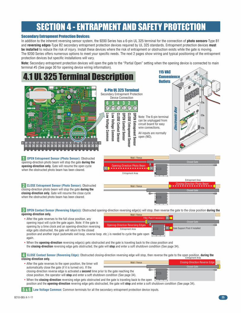
Note: The 6-pin terminal can be unplugged from circuit board for easy wire connections.
All inputs are normally open (NO).
6-Pin UL 325 TerminalSecondary Entrapment Protection
Device Connection
Secondary Entrapment Protection Devices:In addition to the inherent reversing sensor system, the 9200 Series has a 6-pin UL 325 terminal for the connection of photo sensors-Type B1 and reversing edges-Type B2 secondary entrapment protection devices required by UL 325 standards. Entrapment protection devices must be installed to reduce the risk of injury. Install these devices where the risk of entrapment or obstruction exists while the gate is moving.The 9200 Series offers numerous options to meet your specific needs. The next 2 pages show wiring and typical positioning of the entrapment protection devices but specific installations will vary.Note: Secondary entrapment protection devices will open the gate to the “Partial Open” setting when the opening device is connected to main terminal #5 (See page 30 for opening device wiring information).
OPEN Entrapment Sensor
CLOSE Entrapment Sensor
OPEN Contact SensorCLOSE Contact SensorLow Voltage Com
mon
Low Voltage Comm
on
SECTION 4 - ENTRAPMENT AND SAFETY PROTECTION
4.1 UL 325 Terminal Description
123456
Closed Gate
Wall / Fence
Opening-Direction Photo Beam
Wall / FenceFiller Post if necessary
Gate Support Post if Installed
Closed Gate
Wall / FenceClosing-Direction Photo Beam
Closed Gate
Wall / Fence
CLOSE Entrapment Sensor (Photo Sensor): Obstructed closing-direction photo beam will stop the gate during the closing-direction only. Gate will resume the close cycle when the obstructed photo beam has been cleared.
Closed Gate
Low Voltage Common: Common terminals for all the secondary entrapment protection device inputs.
CLOSE Contact Sensor (Reversing Edge): Obstructed closing-direction reversing edge will stop, then reverse the gate to the open position, during the closing-direction only. • After the gate reverses to the open position, the timer will automatically close the gate (if it is turned on). If the closing-direction reverse edge is activated a second time prior to the gate reaching the close position, the operator will stop and enter a soft shutdown condition (See page 34). • When the closing-direction reversing edge gets obstructed and the gate is traveling back to the open position and the opening-direction revering edge gets obstructed, the gate will stop and enter a soft shutdown condition (See page 34).
1
2
3
4
5 & 6
OPEN Entrapment Sensor (Photo Sensor): Obstructed opening-direction photo beam will stop the gate during the opening-direction only. Gate will resume the open cycle when the obstructed photo beam has been cleared.
OPEN Contact Sensor (Reversing Edge(s)): Obstructed opening-direction reversing edge(s) will stop, then reverse the gate to the close position during the opening-direction only. • After the gate reverses to the full close position, any opening input will cycle the gate again. Note: If the gate is opening by a time clock and an opening-direction reversing edge gets obstructed, the gate will return to the closed position and another input (automatic exit loop, reverse loop. etc.) is needed to cycle the gate open again. • When the opening-direction reversing edge(s) gets obstructed and the gate is traveling back to the close position and the closing-direction reversing edge gets obstructed, the gate will stop and enter a soft shutdown condition (See page 34).
Opening-Direction Reversing Edges
Closing-Direction Reverse Edge
Entrapment Area
Entrapment Area
Entrapment Area
Entrapment Area
EXITLO
OPLM
T
REVERSE
LOO
P
REV SENSECLO
SE
P8P7
P6
4404-010
1
2
4
3
1
2
4
3
1
2
4
3
Elec
tron
ic B
ox
TIME
DELAY
EXITLO
OP
LMT
LMT
REVERSE
LOO
P
REV SENSEO
PENREV SENSECLO
SE
1
ON
234 1
ON
2345678
NCNO
P8P7
P6
4404-010
20 19 18 17 16 15 14 13 12 11 10 9 8 7 6 5 4 3 2 1
115 VACConvenienceOutlets

9210-065-X-1-1126
TIME
DELAY
EXITLO
OP
LMT
LMT
REVERSE
LOO
P
REV SENSEO
PENREV SENSECLO
SE
1
ON
234 1
ON
2345678
NCNO
P8P7
P6
4404-101
20 19 18 17 16 15 14 13 12 11 10 9 8 7 6 5 4 3 2 1
Gate
Fra
me
or Lessor Less
Non-Secure Side Outside Property
Secure Side Inside Property
Filler Post or Barrier
Reversing Edge (Open Contact Sensor)
4.2 Secondary Entrapment Protection Device Locations
Photo Sensors (With Filler Post and Reverse Edge) Sample Setup
Typical UL Photo Sensor mounting heightand distance away from gate.
Photo sensors may be installed on either side of gate frame.
5”
21”Typical
If the distance between the gateand wall is greater than 2 1/4”.
Wall
UL s
enso
r mou
nted
on
post
.
UL s
enso
r mou
nted
on
wal
l.
Closed Gate
Wall
Normally Open Normally OpenNormally Open
CommonCommonCommon Common
Normally Open
A filler post or barrier may need to be installed between the gate and wall area to reduce the distance to 2 1/4” or less. A reversing edge should be installed on the post or barrier for safety (See page 8 for more information).
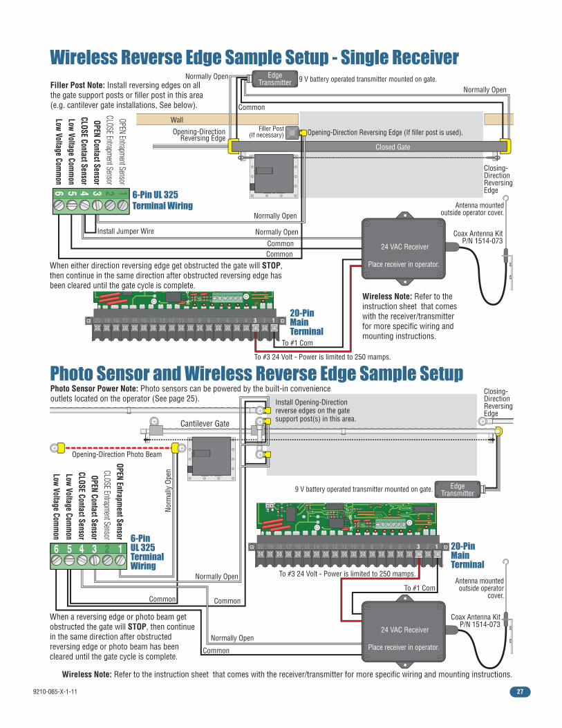
Photo Sensor Power Note: Photo sensors can be powered by the built-in convenience outlets located on the operator (See previous page).
Closing-direction photo sensors wired to UL 325 terminal.
Closing-Direction Photo Beam
Opening-Direction Photo Beam
6-PinUL 325
TerminalWiring
“Reverse” Closing-Direction Option
Filler Post with Opening-Direction Reversing Edge (If necessary, see above)
OPEN Entrapment Sensor
CLOSE Entrapment Sensor
OPEN Contact SensorCLOSE Contact Sensor
Low Voltage Comm
onLow Voltage Com
mon
SW 1, switch 7MUST be OFF.
IF the closing-direction photo sensor is wired to the UL 325 terminal, a closing-direction photo beam that gets obstructed will STOP the gate then resume closing the gate when the obstructed photo beam has been cleared.
IF the closing-direction photo sensor is wired to the #6 main terminal, a closing-direction photo beam that gets obstructed will REVERSE the gate back to the open position.
Gate
Fra
me
5”
1
ON
2345678
SW 1 is Upside-Down on Board
123456
9210-065-X-1-11 27
TIME
DELAY
EXITLO
OP
LMT
LMT
REVERSE
LOO
P
REV SENSEO
PENREV SENSECLO
SE
1
ON
234 1
ON
2345678
NCNO
P8P7
P6
4404-101
20 19 18 17 16 15 14 13 12 11 10 9 8 7 6 5 4 3 2 1
TIME
DELAY
EXITLO
OP
LMT
LMT
REVERSE
LOO
P
REV SENSEO
PENREV SENSECLO
SE
1
ON
234 1
ON
2345678
NCNO
P8P7
P6
4404-101
20 19 18 17 16 15 14 13 12 11 10 9 8 7 6 5 4 3 2 1
9 V battery operated transmitter mounted on gate.
Wireless Reverse Edge Sample Setup - Single Receiver
Photo Sensor and Wireless Reverse Edge Sample Setup
Closed Gate
Wall
Normally Open
Common
Normally OpenInstall Jumper Wire
Common
Normally Open
Normally Open
Common
When either direction reversing edge get obstructed the gate will STOP, then continue in the same direction after obstructed reversing edge has been cleared until the gate cycle is complete.
When a reversing edge or photo beam get obstructed the gate will STOP, then continue in the same direction after obstructed reversing edge or photo beam has been cleared until the gate cycle is complete.
Filler Post Note: Install reversing edges on all the gate support posts or filler post in this area (e.g. cantilever gate installations, See below).
Wireless Note: Refer to the instruction sheet that comes with the receiver/transmitter for more specific wiring and mounting instructions.
Closing-DirectionReversingEdge
Closing-DirectionReversingEdge
Opening-DirectionReversing Edge
Opening-Direction Reversing Edge (If filler post is used).
9 V battery operated transmitter mounted on gate.
Filler Post(If necessary)
EdgeTransmitter
EdgeTransmitter
To #3 24 Volt - Power is limited to 250 mamps.
To #3 24 Volt - Power is limited to 250 mamps.
Coax Antenna KitP/N 1514-073
To #1 Com
To #1 Com
Antenna mounted outside operator cover.
24 VAC Receiver
Place receiver in operator.
123456
6-PinUL 325TerminalWiring
6-Pin UL 325Terminal Wiring
Normally Open
Norm
ally
Ope
n
CommonCommon
Opening-Direction Photo Beam
Normally Open
Common
Wireless Note: Refer to the instruction sheet that comes with the receiver/transmitter for more specific wiring and mounting instructions.
20-PinMainTerminal
20-PinMainTerminal
Photo Sensor Power Note: Photo sensors can be powered by the built-in convenience outlets located on the operator (See page 25). Install Opening-Direction
reverse edges on the gate support post(s) in this area.
123456
Cantilever Gate
Coax Antenna KitP/N 1514-073
Antenna mounted outside operator
cover.
OPEN Entrapment SensorCLOSE Entrapment Sensor
OPEN Contact SensorCLOSE Contact SensorLow Voltage Com
mon
Low Voltage Comm
on
OPEN Entrapment Sensor
CLOSE Entrapment SensorOPEN Contact Sensor
CLOSE Contact SensorLow Voltage Com
mon
Low Voltage Comm
on
24 VAC Receiver
Place receiver in operator.
9210-065-X-1-1128
TIME
DELAY
EXITLO
OP
LMT
LMT
REVERSE
LOO
P
REV SENSEO
PENREV SENSECLO
SE
1
ON
234 1
ON
2345678
NCNO
P8P7
P6
4404-010
20 19 18 17 16 15 14 13 12 11 10 9 8 7 6 5 4 3 2 1
Reverse Loop
Reverse Loop
Automatic Exit
Loop
4 Ft. Min. to
avoid gate
movement interference.
4 Ft. Min. to
avoid gate
movement interference.
4 Ft. Min. to
avoid
reverse loop interference.
9410
Note: Loop detector wiring is shown for DoorKing plug-in loop detector P/N 9410-010 (Single Channel). If other loop detectors are used, refer to the installation instructions supplied with those detectors for wiring and separate power instructions.
Reverse LoopsReverse loops are placed on each side of the gate to prevent the gate from closing on a vehicle in the gate’s path. They will stop or reverse the cycling of the gate while a vehicle is in or near the gate’s pathway.
9410
Single Channel Single Channel
4.3 Loop Detector Wiring
Loop Lead In WireLoop Lead In Wires
DoorKingPlug-in
Loop Detectors
Note: SW 1, switch 7 must be set for the reverse loops. See page 21 for more information about SW 1, switch 7 ON/OFF options.
A B
Reverse loop lead-in wires are twisted approx. 6 twists per foot and are wired in series.
A
LOOP
1
WARNING
MOVING GATE CAN CAUSE
Operate gate only when gate area is in sight
and free of people and obstructions.
Do not allow children to play in gate area
or operate gate.Do not stand in gate path or walk through
path while gate is moving.
Read owner’s manual and safety instructions.
SERIOUS INJURY OR DEATH
CLASS
CERTIFIED TO
CAN/CSA C22.2 NO. 247
CONFORMS TO
ANSI/UL-325
VEHICULAR GATE OPERATORHP
53382
MODELSERIALVOLTS
PHASE
AMPS
60 Hz
MAX GATE LOADDoorKing, Inc., Inglewood, CA
PVC Conduit
Automatic Exit LoopAutomatically opens the gate for exiting vehicles without having to use a transmitter or keypad. The exit loop can be placed a minimum of 4 feet away from the reverse loop or far enough away from the gate so the gate has started opening or even completely opened by the time you drive up to it (Free exit).
To help protect the operator from accidentally closing on vehicles in the gate’s path, DoorKing highly recommends that loops and loop detectors be installed. Loops are laid underneath, cut into asphalt or concrete driveways or buried beneath gravel and earth driveways. A loop detection system will sense a vehicle like a metal detector and send a signal to the gate operator preventing the gate from automatically opening or closing on a vehicle when it is in the gate’s path. DoorKing recommends that a licensed installer perform this work.
B
LOOP
1
PVC Conduit
DoorKing offers a free “Loop and Loop-Detectors Information Manual” PDF located at DoorKing’s web site for more information. www.dkaccess.com
Exit loop lead-in wires are twisted approx. 6 twists per foot.
Exit Loop Port
Reverse Loop Port
1
ON
2345678
SW 1 is Upside-Down on Board
1
ON
2345678
SW 1 is Upside-Down on Board
1
ON
2345678
SW 1 is Upside-Down on Board
Note: The plug-in exit loop detector can be wired to partially open the gate if SW 1, switch 3 is turned OFF. A jumper wire must be connected from terminal #4 to terminal #5 (See next page for more information).
Exit Loop Partial Open
SW 1, switch 3 must be ON to FULLY open gate (Normal function).
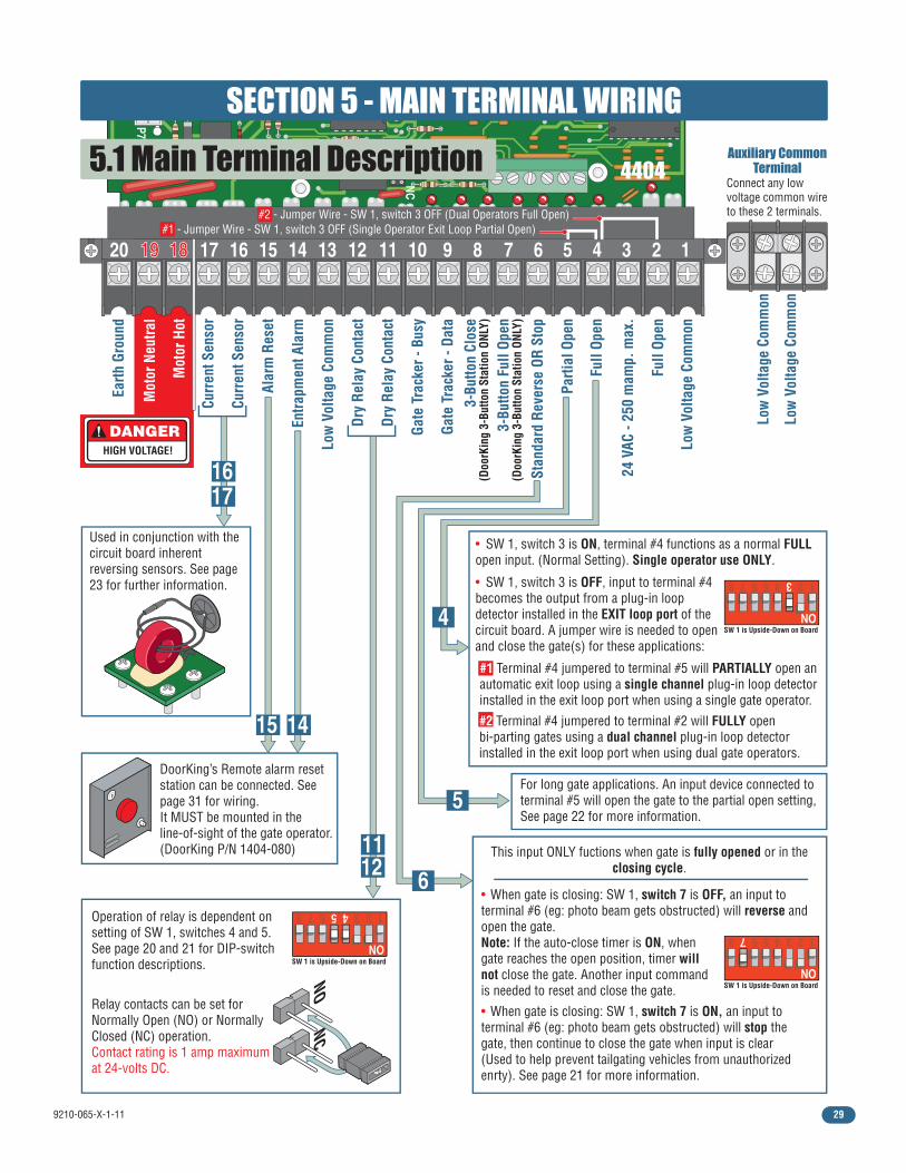
9210-065-X-1-11 29
NCNO
P7
20 1919 1818 17 16 15 14 13 12 11 10 9 8 7 6 5 4 3 2 1Cu
rren
t Sen
sor
Curr
ent S
enso
r
Earth
Gro
und
Mot
or H
ot
Mot
or N
eutra
l
Dry
Rela
y Co
ntac
t
Gate
Tra
cker
- Da
ta
Gate
Tra
cker
- Bu
sy
Entra
pmen
t Ala
rm
Alar
m R
eset
Full
Open
Dry
Rela
y Co
ntac
t
24 V
AC -
250
mam
p. m
ax.
Full
Open
Parti
al O
pen
Stan
dard
Rev
erse
OR
Stop
Low
Vol
tage
Com
mon
Low
Vol
tage
Com
mon
Low
Vol
tage
Com
mon
Low
Vol
tage
Com
mon
3-Bu
tton
Full
Open
(Doo
rKin
g 3-
Butto
n St
atio
n ON
LY)
3-Bu
tton
Clos
e(D
oorK
ing
3-Bu
tton
Stat
ion
ONLY
)
4404
Operation of relay is dependent on setting of SW 1, switches 4 and 5.See page 20 and 21 for DIP-switch function descriptions.
Relay contacts can be set for Normally Open (NO) or Normally Closed (NC) operation. Contact rating is 1 amp maximum at 24-volts DC.
NCNO
DoorKing’s Remote alarm reset station can be connected. See page 31 for wiring.It MUST be mounted in the line-of-sight of the gate operator.(DoorKing P/N 1404-080)
Used in conjunction with the circuit board inherent reversing sensors. See page 23 for further information.
DANGERHIGH VOLTAGE!
5.1 Main Terminal Description
1
ON
2345678
SW 1 is Upside-Down on Board
1
ON
2345678
SW 1 is Upside-Down on Board
1
ON
2345678
SW 1 is Upside-Down on Board
This input ONLY fuctions when gate is fully opened or in the closing cycle.
• When gate is closing: SW 1, switch 7 is OFF, an input to terminal #6 (eg: photo beam gets obstructed) will reverse and open the gate.Note: If the auto-close timer is ON, when gate reaches the open position, timer will not close the gate. Another input command is needed to reset and close the gate.
• When gate is closing: SW 1, switch 7 is ON, an input to terminal #6 (eg: photo beam gets obstructed) will stop the gate, then continue to close the gate when input is clear (Used to help prevent tailgating vehicles from unauthorized enrty). See page 21 for more information.
For long gate applications. An input device connected to terminal #5 will open the gate to the partial open setting, See page 22 for more information.
Auxiliary CommonTerminal
Connect any low voltage common wire to these 2 terminals.
#1 - Jumper Wire - SW 1, switch 3 OFF (Single Operator Exit Loop Partial Open) #2 - Jumper Wire - SW 1, switch 3 OFF (Dual Operators Full Open)
1617
1112
15 14
6
4
5
SECTION 5 - MAIN TERMINAL WIRING
#1 Terminal #4 jumpered to terminal #5 will PARTIALLY open an automatic exit loop using a single channel plug-in loop detector installed in the exit loop port when using a single gate operator.
#2 Terminal #4 jumpered to terminal #2 will FULLY open bi-parting gates using a dual channel plug-in loop detector installed in the exit loop port when using dual gate operators.
• SW 1, switch 3 is ON, terminal #4 functions as a normal FULL open input. (Normal Setting). Single operator use ONLY.
• SW 1, switch 3 is OFF, input to terminal #4 becomes the output from a plug-in loop detector installed in the EXIT loop port of the circuit board. A jumper wire is needed to open and close the gate(s) for these applications:
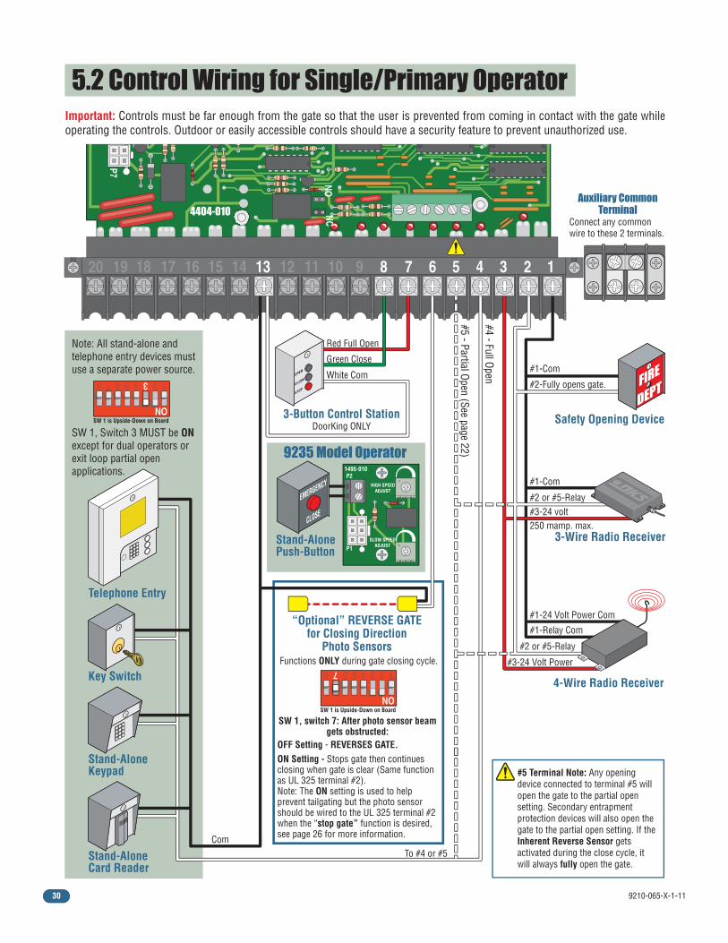
9210-065-X-1-1130
NCNO
P7
20 19 18 17 16 15 14 13 12 11 10 9 8 7 6 5 4 3 2 1
Red Full Open
Green Close
White Com
Key Switch
Stand-AloneKeypad
Stand-AloneCard Reader
Telephone Entry
3-Button Control StationDoorKing ONLY
Functions ONLY during gate closing cycle.
Note: All stand-alone and telephone entry devices must use a separate power source.
Important: Controls must be far enough from the gate so that the user is prevented from coming in contact with the gate while operating the controls. Outdoor or easily accessible controls should have a security feature to prevent unauthorized use.
“Optional” REVERSE GATEfor Closing Direction
Photo Sensors
#1-Com
#1-Com
#5 - Partial Open (See page 22)
#4 - Full Open
ComTo #4 or #5
#2 or #5-Relay
250 mamp. max.#3-24 volt
#1-Relay Com
#2 or #5-Relay
#1-24 Volt Power Com
#3-24 Volt Power
4-Wire Radio Receiver
#2-Fully opens gate.
3-Wire Radio Receiver
Safety Opening Device
4404-010
Stand-AlonePush-Button
9235 Model Operator
HIGH SPEEDADJUST
SLOW SPEEDADJUSTP1
P21495-010
SW 1, switch 7: After photo sensor beam gets obstructed:
OFF Setting - REVERSES GATE.ON Setting - Stops gate then continues closing when gate is clear (Same function as UL 325 terminal #2).Note: The ON setting is used to help prevent tailgating but the photo sensor should be wired to the UL 325 terminal #2 when the “stop gate” function is desired, see page 26 for more information.
#5 Terminal Note: Any opening device connected to terminal #5 will open the gate to the partial open setting. Secondary entrapment protection devices will also open the gate to the partial open setting. If the Inherent Reverse Sensor gets activated during the close cycle, it will always fully open the gate.
1
ON
2345678
SW 1 is Upside-Down on Board
1
ON
2345678
SW 1 is Upside-Down on Board
Auxiliary CommonTerminal
Connect any common wire to these 2 terminals.
SW 1, Switch 3 MUST be ON except for dual operators or exit loop partial open applications.
5.2 Control Wiring for Single/Primary Operator
EMERGENCY
CLOSE
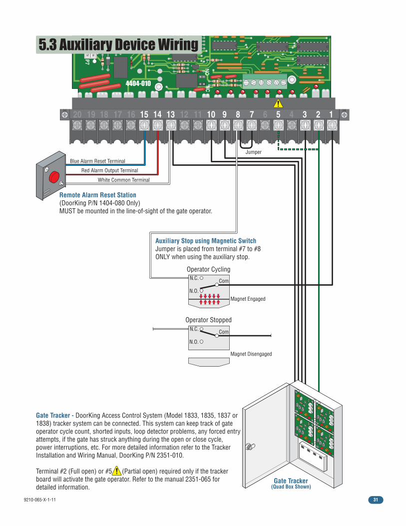
9210-065-X-1-11 31
NC NO
P7
20 19 18 17 16 15 14 13 12 11 10 9 8 7 6 5 4 3 2 1
Gate Tracker (Quad Box Shown)
Remote Alarm Reset Station(DoorKing P/N 1404-080 Only)MUST be mounted in the line-of-sight of the gate operator.
Auxiliary Stop using Magnetic SwitchJumper is placed from terminal #7 to #8 ONLY when using the auxiliary stop.
Red Alarm Output Terminal
Blue Alarm Reset Terminal
White Common Terminal
Jumper
N.O.
N.C. Com
Operator Cycling
Magnet Engaged
5.3 Auxiliary Device Wiring
Gate Tracker - DoorKing Access Control System (Model 1833, 1835, 1837 or 1838) tracker system can be connected. This system can keep track of gate operator cycle count, shorted inputs, loop detector problems, any forced entry attempts, if the gate has struck anything during the open or close cycle, power interruptions, etc. For more detailed information refer to the Tracker Installation and Wiring Manual, DoorKing P/N 2351-010. Terminal #2 (Full open) or #5 (Partial open) required only if the tracker board will activate the gate operator. Refer to the manual 2351-065 for detailed information.
N.O.
N.C. Com
Operator Stopped
Magnet Disengaged
4404-010
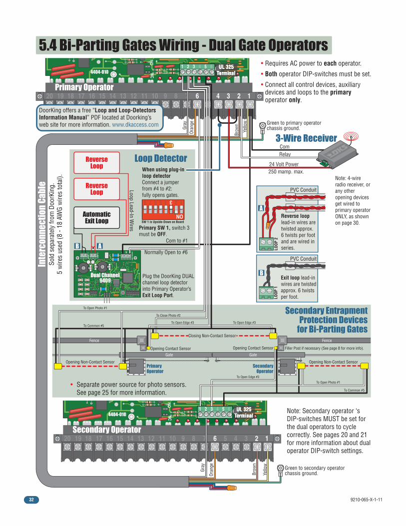
9210-065-X-1-1132
NC NO
P7
20 19 18 17 16 15 14 13 12 11 10 9 8 7 6 5 4 3 2 1
1 2 3 4 5 6 UL 325 Terminal UL 325
Terminal UL 325
Terminal UL 325
Terminal
Primary Operator
NC NO
P7
20 19 18 17 16 15 14 13 12 11 10 9 8 7 6 5 4 3 2 1
1 2 3 4 5 6 UL 325 Terminal UL 325
Terminal UL 325
Terminal UL 325
Terminal
Secondary Operator
5.4 Bi-Parting Gates Wiring - Dual Gate Operators
Plug the DoorKing DUALchannel loop detectorinto Primary Operator’sExit Loop Port.
Dual Channel9409
24 Volt Power
RelayCom
Green to primary operator chassis ground.
Com to #1
Normally Open to #6
AutomaticExit Loop
ReverseLoop
ReverseLoop
Loop Lead-In Wires
Loop Detector
3-Wire Receiver
250 mamp. max.
• Requires AC power to each operator.
• Both operator DIP-switches must be set.
• Connect all control devices, auxiliary devices and loops to the primary operator only.
Secondary EntrapmentProtection Devices
for Bi-Parting Gates
SecondaryOperator
PrimaryOperator
To Close Photo #2
To Open Edge #3 To Open Edge #3
To Open Edge #3
To Common #5
To Common #5
To Open Photo #1
To Open Photo #1
Fence
Gate
Opening Non-Contact Sensor
Closing Non-Contact Sensor
Opening Contact Sensor Opening Contact Sensor
Opening Non-Contact Sensor
Fence
Gate
Yello
w
Brow
n
Oran
ge
Gray
Green to secondary operator chassis ground.
Yello
w
Brow
n
Oran
ge
Gray
Primary SW 1, switch 3 must be OFF.
Inte
rcon
nect
ion
Cabl
eSo
ld s
epar
atel
y fro
m D
oorK
ing.
5 w
ires
used
(8 -
18 A
WG
wire
s to
tal).
4404-010
4404-010
• Separate power source for photo sensors. See page 25 for more information.
1
ON
2345678
SW 1 is Upside-Down on Board
When using plug-in loop detectorConnect a jumper from #4 to #2:fully opens gates.
Filler Post if necessary (See page 8 for more info).
Note: Secondary operator ‘s DIP-switches MUST be set for the dual operators to cycle correctly. See pages 20 and 21 for more information about dual operator DIP-switch settings.
Note: 4-wire radio receiver, or any other opening devices get wired to primary operator ONLY, as shown on page 30.
B
B
LOOP
1Exit loop lead-in wires are twisted approx. 6 twists per foot.
Reverse loop lead-in wires are twisted approx. 6 twists per foot and are wired in series.
A
A LOOP
2
PVC Conduit
PVC Conduit
DoorKing offers a free “Loop and Loop-Detectors Information Manual” PDF located at Doorking’s web site for more information. www.dkaccess.com
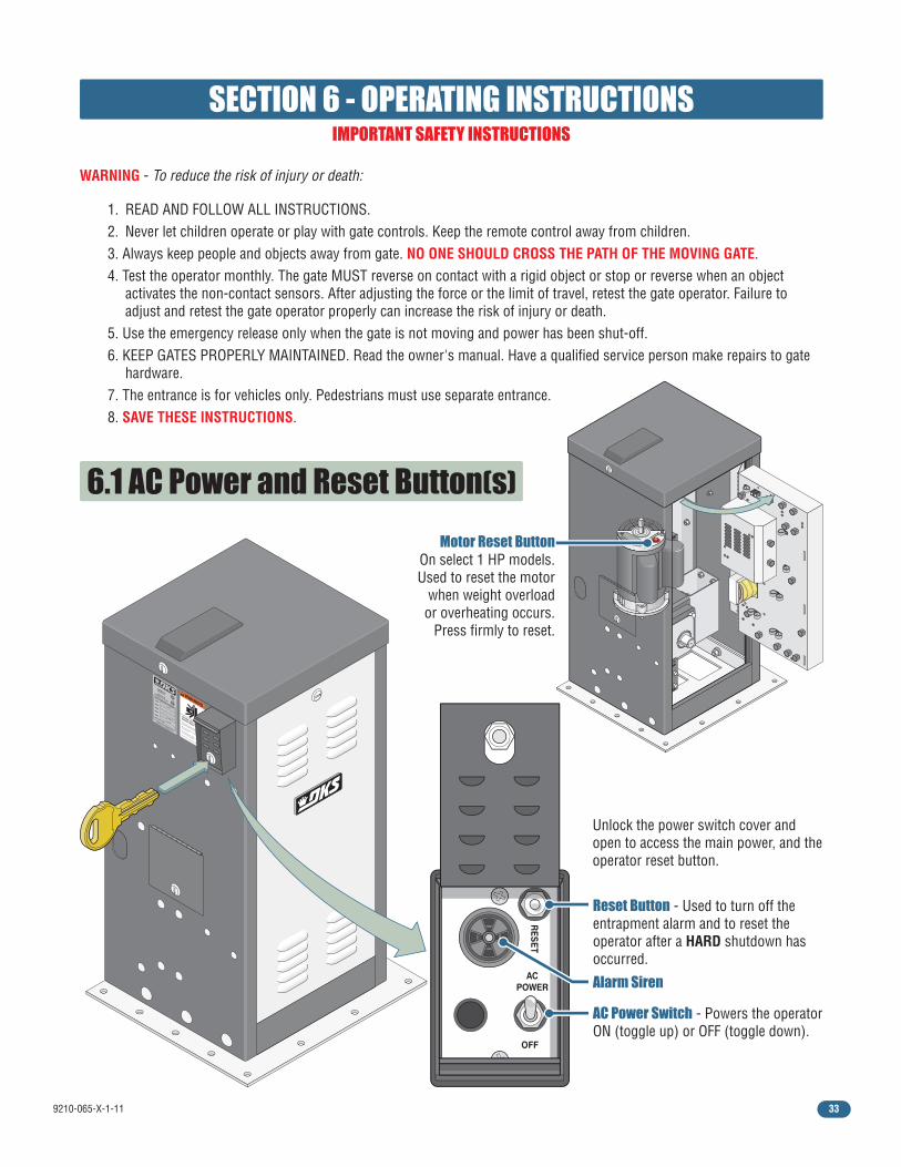
9210-065-X-1-11 33
WARNING
MOVING GATE CAN CAUSE
Operate gate only when gate area is in sight
and free of people and obstructions.
Do not allow children to play in gate area
or operate gate.
Do not stand in gate path or walk through
path while gate is moving.
Read owner’s manual and safety instructions.
SERIOUS INJURY OR DEATH
CLASS
CERTIFIED TO
CAN/CSA C22.2 NO. 247
CONFORMS TO
ANSI/UL-325
VEHICULAR GATE OPERATOR HP
53382
MODEL SERIAL VOLTS
PHASE
AMPS
60 Hz
MAX GATE LOAD DoorKing, Inc., Inglewood, CA
SECTION 6 - OPERATING INSTRUCTIONS
WARNING - To reduce the risk of injury or death:
1. READ AND FOLLOW ALL INSTRUCTIONS. 2. Never let children operate or play with gate controls. Keep the remote control away from children. 3. Always keep people and objects away from gate. NO ONE SHOULD CROSS THE PATH OF THE MOVING GATE. 4. Test the operator monthly. The gate MUST reverse on contact with a rigid object or stop or reverse when an object activates the non-contact sensors. After adjusting the force or the limit of travel, retest the gate operator. Failure to adjust and retest the gate operator properly can increase the risk of injury or death. 5. Use the emergency release only when the gate is not moving and power has been shut-off. 6. KEEP GATES PROPERLY MAINTAINED. Read the owner's manual. Have a qualified service person make repairs to gate hardware. 7. The entrance is for vehicles only. Pedestrians must use separate entrance. 8. SAVE THESE INSTRUCTIONS.
Unlock the power switch cover and open to access the main power, and the operator reset button.
AC POWER
OFF
RE
SE
T
6.1 AC Power and Reset Button(s)
Reset Button - Used to turn off the entrapment alarm and to reset the operator after a HARD shutdown has occurred.
Alarm Siren
AC Power Switch - Powers the operator ON (toggle up) or OFF (toggle down).
IMPORTANT SAFETY INSTRUCTIONS
Motor Reset Button On select 1 HP models. Used to reset the motor
when weight overload or overheating occurs.
Press firmly to reset.
R E S E T
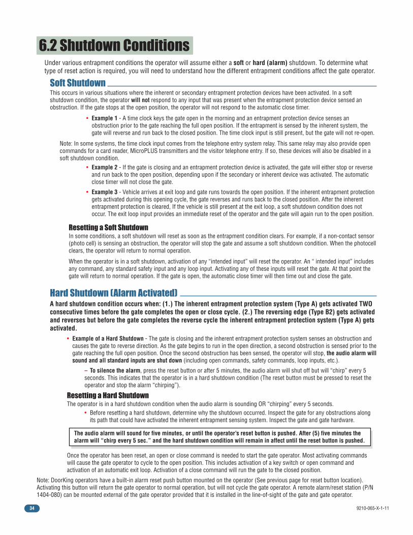
9210-065-X-1-1134
6.2 Shutdown ConditionsUnder various entrapment conditions the operator will assume either a soft or hard (alarm) shutdown. To determine what type of reset action is required, you will need to understand how the different entrapment conditions affect the gate operator.
This occurs in various situations where the inherent or secondary entrapment protection devices have been activated. In a soft shutdown condition, the operator will not respond to any input that was present when the entrapment protection device sensed an obstruction. If the gate stops at the open position, the operator will not respond to the automatic close timer.
Note: In some systems, the time clock input comes from the telephone entry system relay. This same relay may also provide open commands for a card reader, MicroPLUS transmitters and the visitor telephone entry. If so, these devices will also be disabled in a soft shutdown condition.
In some conditions, a soft shutdown will reset as soon as the entrapment condition clears. For example, if a non-contact sensor (photo cell) is sensing an obstruction, the operator will stop the gate and assume a soft shutdown condition. When the photocell clears, the operator will return to normal operation.
When the operator is in a soft shutdown, activation of any “intended input” will reset the operator. An “ intended input” includes any command, any standard safety input and any loop input. Activating any of these inputs will reset the gate. At that point the gate will return to normal operation. If the gate is open, the automatic close timer will then time out and close the gate.
• Example 1 - A time clock keys the gate open in the morning and an entrapment protection device senses an obstruction prior to the gate reaching the full open position. If the entrapment is sensed by the inherent system, the gate will reverse and run back to the closed position. The time clock input is still present, but the gate will not re-open.
• Example 2 - If the gate is closing and an entrapment protection device is activated, the gate will either stop or reverse and run back to the open position, depending upon if the secondary or inherent device was activated. The automatic close timer will not close the gate.
• Example 3 - Vehicle arrives at exit loop and gate runs towards the open position. If the inherent entrapment protection gets activated during this opening cycle, the gate reverses and runs back to the closed position. After the inherent entrapment protection is cleared, If the vehicle is still present at the exit loop, a soft shutdown condition does not occur. The exit loop input provides an immediate reset of the operator and the gate will again run to the open position.
Soft Shutdown
Resetting a Soft Shutdown
Hard Shutdown (Alarm Activated)
The audio alarm will sound for five minutes, or until the operator’s reset button is pushed. After (5) five minutes the alarm will “chirp every 5 sec.” and the hard shutdown condition will remain in affect until the reset button is pushed.
• Example of a Hard Shutdown - The gate is closing and the inherent entrapment protection system senses an obstruction and causes the gate to reverse direction. As the gate begins to run in the open direction, a second obstruction is sensed prior to the gate reaching the full open position. Once the second obstruction has been sensed, the operator will stop, the audio alarm will sound and all standard inputs are shut down (including open commands, safety commands, loop inputs, etc.).
A hard shutdown condition occurs when: (1.) The inherent entrapment protection system (Type A) gets activated TWO consecutive times before the gate completes the open or close cycle. (2.) The reversing edge (Type B2) gets activated and reverses but before the gate completes the reverse cycle the inherent entrapment protection system (Type A) gets activated.
Note: DoorKing operators have a built-in alarm reset push button mounted on the operator (See previous page for reset button location). Activating this button will return the gate operator to normal operation, but will not cycle the gate operator. A remote alarm/reset station (P/N 1404-080) can be mounted external of the gate operator provided that it is installed in the line-of-sight of the gate and gate operator.
The operator is in a hard shutdown condition when the audio alarm is sounding OR “chirping” every 5 seconds.
Once the operator has been reset, an open or close command is needed to start the gate operator. Most activating commands will cause the gate operator to cycle to the open position. This includes activation of a key switch or open command and activation of an automatic exit loop. Activation of a close command will run the gate to the closed position.
• Before resetting a hard shutdown, determine why the shutdown occurred. Inspect the gate for any obstructions along its path that could have activated the inherent entrapment sensing system. Inspect the gate and gate hardware.
Resetting a Hard Shutdown
– To silence the alarm, press the reset button or after 5 minutes, the audio alarm will shut off but will “chirp” every 5 seconds. This indicates that the operator is in a hard shutdown condition (The reset button must be pressed to reset the operator and stop the alarm “chirping”).
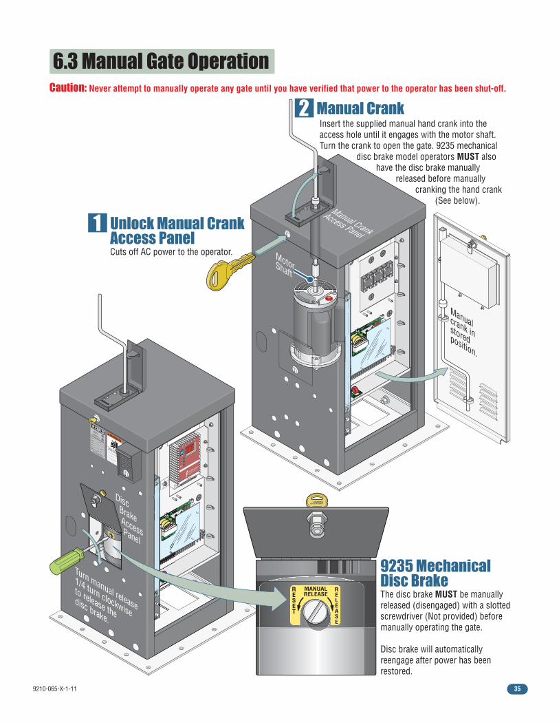
9210-065-X-1-11 35
WARNING
MOVING GATE CAN CAUSE
Operate gate only when gate area is in sight
and free of people and obstructions.
Do not allow children to play in gate area
or operate gate.
Do not stand in gate path or walk through
path while gate is moving.
Read owner’s manual and safety instructions.
SERIOUS INJURY OR DEATH
CLASS
CERTIFIED TO
CAN/CSA C22.2 NO. 247
CONFORMS TO
ANSI/UL-325
VEHICULAR GATE OPERATOR HP
53382
MODEL SERIAL VOLTS
PHASE
AMPS
60 Hz
MAX GATE LOAD DoorKing, Inc., Inglewood, CA
EXIT LO
OP LM
T
REVERSE
LOO
P
REV SENSE CLO
SE
6.3 Manual Gate OperationCaution: Never attempt to manually operate any gate until you have verified that power to the operator has been shut-off.
Unlock Manual Crank Access Panel Cuts off AC power to the operator.
Manual Crank
9235 Mechanical Disc BrakeThe disc brake MUST be manually released (disengaged) with a slotted screwdriver (Not provided) before manually operating the gate.
Disc brake will automatically reengage after power has been restored.
R E S E T
EXIT LO
OP LM
T
REVERSE
LOO
P
REV SENSE CLO
SE
1
2
4
3
1
2
4
3
1
2
4
3
Manual Crank
Access Panel
Insert the supplied manual hand crank into the access hole until it engages with the motor shaft. Turn the crank to open the gate. 9235 mechanical
disc brake model operators MUST also have the disc brake manually
released before manually cranking the hand crank
(See below).
MotorShaft
Manualcrank instoredposition.
Turn manual release
1/4 turn clockwise
to release thedisc brake.
MANUAL RELEASE
R E S E T
R E L E A S E
MANUAL RELEASE
R E S E T R
E L E A S E
1
2
1 2 5 6 11 13
A 13B 13
E 25 16
17
L1 L2 L3 B- B+
Mode
EPM
0 0 0
SCM series
basic I/O control
1 ft/s
.5 ft/s
0 ft/s
2 ft/s
1.5 ft/s
Disc Brake Access Panel
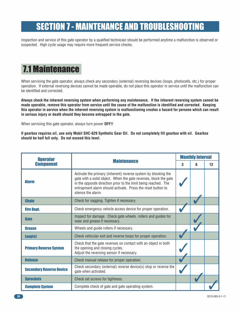
9210-065-X-1-1136
7.1 Maintenance
SECTION 7 - MAINTENANCE AND TROUBLESHOOTINGInspection and service of this gate operator by a qualified technician should be performed anytime a malfunction is observed or suspected. High cycle usage may require more frequent service checks.
When servicing the gate operator, always check any secondary (external) reversing devices (loops, photocells, etc.) for proper operation. If external reversing devices cannot be made operable, do not place this operator in service until the malfunction can be identified and corrected.
Always check the inherent reversing system when performing any maintenance. If the inherent reversing system cannot be made operable, remove this operator from service until the cause of the malfunction is identified and corrected. Keeping this operator in service when the inherent reversing system is malfunctioning creates a hazard for persons which can result in serious injury or death should they become entrapped in the gate.
When servicing this gate operator, always turn power OFF!!
If gearbox requires oil, use only Mobil SHC-629 Synthetic Gear Oil. Do not completely fill gearbox with oil. Gearbox should be half full only. Do not exceed this level.
Operator Component
Maintenance Monthly Interval
6 3 12
Alarm
Chain
✓
✓
✓ ✓
✓
✓
✓ ✓
✓
Fire Dept.
Gate
Loop(s)
Release
Primary Reverse System
Secondary Reverse Device
Complete System
Activate the primary (inherent) reverse system by blocking the gate with a solid object. When the gate reverses, block the gate in the opposite direction prior to the limit being reached. The entrapment alarm should activate. Press the reset button to silence the alarm.
Check for sagging. Tighten if necessary.
Check vehicular exit and reverse loops for proper operation.
Check manual release for proper operation.
Complete check of gate and gate operating system.
Check emergency vehicle access device for proper operation.
Grease Wheels and guide rollers if necessary.
Inspect for damage. Check gate wheels. rollers and guides for wear and grease if necessary.
Check that the gate reverses on contact with an object in both the opening and closing cycles. Adjust the reversing sensor if necessary.
Check secondary (external) reverse device(s) stop or reverse the gate when activated.
Sprockets Check set screws for tightness. ✓
✓
9210-065-X-1-11 37
7.3 Troubleshooting
7.2 Built-In Diagnostic Tests
Have a good VOM meter to check voltages and continuity. A Meg-Ohm meter capable of checking up to 500 meg-ohms of resistance is necessary to properly check the integrity of the ground loops. When a malfunction occurs, isolate the problem to one of three areas: 1. the operator, 2. the loop system, 3. the keying devices. Use caution when checking high voltage terminals, motor capacitor and the motor.
This gate operator is designed with built-in diagnostics that will alert you to potential or existing problems that the microproces-sor has detected. Specific fault conditions are checked and the operator will signal that a fault exist through the built-in alarm.
1. Check the input indicator LEDs. They should only come ON when a keying device (card reader, push button, etc.) is activated. If any of the input LEDs are ON continuously, this will cause the gate operator to hold open. Disconnect the keying devices one at a time until the LED goes OFF.
2. Check any external secondary entrapment protection devices. Any short or malfunction in these devices can cause the gate operator to stop or to hold open.
3. A malfunction in a loop or loop detector can cause the gate operator to hold open, or to not detect a vehicle when it is present over the loop. Pull the loop detector circuit boards from the loop ports on the operator circuit board. If the malfunction persists, the problem is not with the loop system. For more information on trouble shooting loops and loop detectors, refer to your loop detector instruction sheet and to the DoorKing Loop and Loop Detector Information Manual located on DoorKing’s web site.
4. Check to be sure that there are no shorted or open control wires from the keying devices to the gate operator. If a keying device fails to open the gate, press the Key Switch or momentarily jumper across terminals 1 and 4 on the operator circuit board. If the gate operator starts, this indicates that a problem exist with the keying device and is not with the gate operator.
5. If a three-button control station (open-close-stop) is connected to this gate operator, check for proper wiring. Only a DoorKing three button control station (P/N 1200-006 or 007) can be used with this gate operator. Others will cause a malfunction.
6. Check the high voltage supply. A voltage drop on the supply line (usually caused by using too small supply voltage wires) will cause the operator to malfunction. Refer to the wire size chart in section 2.1 on page 17.
Constant alarm is heard when power is applied: This indicates that the limit switch wire harness is not connected to the circuit board. In this condition, the operator will not run and the tone will continue until the fault is corrected. Check to be sure that the limit switch plug is properly inserted into the limit switch plug on the circuit board.
Constant alarm is heard: This indicates that the operator is in a hard shutdown condition (section 6.2 on page 34). The tone will continue to sound for five minutes, and then will beep once every five seconds. The operator-reset button must be pressed or power must be removed and then reapplied to return the operator to normal operation.
Short “chirp” is heard every five seconds: This indicates that the operator has been in a hard shutdown condition in excess of five minutes. This will continue until the operator-reset button is pressed or until power is removed from the operator (section 6.2 on page 34).
Operator runs for 1 second and stops, two short “chirps” are heard: This indicates that there may be a fault with the current sensor circuit.
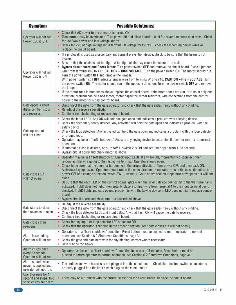
9210-065-X-1-1138
• Check the input LEDs. Any ON will hold the gate open and indicates a problem with a keying device. • Check the secondary safety devices. Any activated will hold the gate open and indicates a problem with the safety device. • Check the loop detectors. Any activated can hold the gate open and indicates a problem with the loop detector or ground loop. • Operator may be in a “soft shutdown.” Activate any keying device to determine if operator returns to normal operation. • If automatic close is desired, be sure SW 1, switch 2 is ON and set timer open from 1-23 seconds. • Bypass circuit board and check motor as above.
Gate opens but will not close.
Gate closes but will not open.
• Operator may be in a “soft shutdown.” Check input LEDs. If any are ON, momentarily disconnect, then re-connect the wire going to the respective terminal. Operator should open. • Check to be sure that the operator is running in the proper direction. Turn power OFF, and then back ON. Activate a keying device. Operator should run in the open direction. If operator runs in the close direction, turn power OFF and change direction switch SW 1, switch 1. Go to above section if operator now opens but will not close. • Be sure that the each LED on the control board lights when the keying device connected to the that terminal is activated. If LED does not light, momentarily place a jumper wire from terminal 1 to the input terminal being checked. If LED lights and gate opens, problem is with the keying device. If LED does not light, replace control board. • Bypass circuit board and check motor as described above.
• Disconnect the gate from the gate operator and check that the gate slides freely without any binding.• Re-adjust the reverse sensitivity.• Continue troubleshooting or replace circuit board.
Gate opens a short distance, then stops and reverses.
Gate closes then re-opens.
Gate starts to close, then reverses to open.
Operator runs for 1 second and stops, two short chirps are heard.
Alarm chirps once every 5 seconds. Operator will not run.
Alarm is sounding. Operator will not run.
Alarm sounds when power is applied and operator will not run.
• Re-adjust the reverse sensitivity.• Disconnect the gate from the gate operator and check that the gate slides freely without any binding.• Check the loop detector LEDs and input LEDs. Any that flash ON will cause the gate to reverse.• Continue troubleshooting or replace circuit board.
• Operator has been in a “hard shutdown” condition in excess of 5 minutes. Reset button must be pushed to return operator to normal operation, see Section 6.2 Shutdown Conditions, page 34.
• The limit switch wire harness is not plugged into the circuit board. Check that the limit switch connector is properly plugged into the limit switch plug on the circuit board.
• There may be a problem with the current sensor on the circuit board. Replace the circuit board.
• Operator is in a “hard shutdown” condition. Reset button must be pushed to return operator to normal operation, see Section 6.2 Shutdown Conditions, page 34.• Check the gate and gate hardware for any binding, correct where necessary.• Gate may be too heavy.
• Check for any input or loop detector LED’s that are ON.• Check that the operator is running in the proper direction (see “gate closes but will not open”).
Symptom Possible Solution(s)
• Check that AC power to the operator is turned ON. • Transformer may be overheated. Turn power off and allow board to cool for several minutes then retest. Check for low VAC power and low voltage shorts. • Check for VAC at high voltage input terminal. If voltage measures 0, check the incoming power wires or replace the circuit board. • If a photocell is used as a secondary entrapment prevention device, check to be sure that the beam is not blocked.• Be sure that the chain is not too tight. A too tight chain may cause the operator to stall.• Bypass circuit board and Check Motor: Turn power switch OFF and remove the circuit board. Place a jumper wire from terminal #18 to #17. CAUTION – HIGH VOLTAGE. Turn the power switch ON. The motor should run. Turn the power switch OFF and remove the jumper. With power switch still OFF, place a jumper wire from terminal #18 to #16. CAUTION – HIGH VOLTAGE. Turn the power switch ON. The motor should run in the opposite direction. Turn the power switch OFF and remove the jumper.• If the motor runs in both steps above, replace the control board. If the motor does not run, or runs in only one direction, problem can be a bad motor, motor capacitor, motor resistors, wire connections from the control board to the motor or a bad control board.
Operator will not run. Power LED is OFF.
Operator will not run. Power LED is ON.

9210-065-X-1-11 39
7.4 Accessory ItemsThe following accessory items are available for the series 9200 slide gate operators.
Contact Sensors - For use as a secondary entrapment protection device. Miller Edge, Inc., MGO20, MGR20, MGS20
Chain Tray Kit - 10 Ft. section. Sections connect together to fit any length gate. P/N 2601-270
Pedestal Mounting Stand - Heavy-duty pedestal mounting stand for the 9200 series operator. P/N 9200-135
Heater and Fan Kit - Recommended for cold weather climates.P/N 1601-195: 115 VAC models, P/N 1601-197: 208/230 VAC models
Photo Cell - Non-contact (photocell) sensors for use as a secondary entrapment protection device. MMTC, Inc. Model IR55 - P/N 8080-010 MMTC, Inc. Model 60-278 - P/N 8080-011 Carlo Gavazzi Type PMP12 - P/N 8080-030 Carlo Gavazzi Type PMT - P/N 8080-031
Loop Detector - Detectors plug directly into ports on circuit board simplifying wiring. Single channel detector - P/N 9410-010 Dual channel detector - P/N 9409-010
Loop Wire - 18 AWG loop wire with XLPE insulation is ideal for ground loops. Available in 500 and 1000 foot rolls. Red, blue or black insulation.
Pre-Fab Loops - Prefabricated ground loops. 24-foot circumference with 50-foot lead-in. Available in yellow, red or blue jackets. Not for use in asphalt roadways.
Loop Test Meter - Meg-ohm meter checks the integrity of ground loops. P/N 9401-045
3-Button Control Station - Provides open-close-stop manual operation of the gate. Stand Alone Box - P/N 1200-006 Interior (fits in single gang box) - P/N 1200-007
Interconnection Cable - Interconnect wire cable contains all the necessary wires to interconnect primary / secondary operators. Cable length: 30 ft. - P/N 2600-755 40 ft. - P/N 2600-756 50 ft. - P/N 2600-757
Time Clock - 7 day and 365 day time clocks can be used to automatically open gate at pre-set time and days. Compact clock fits inside the operator. 7 day clock - P/N 2600-791 365 day clock - P/N 2600-795
V-Wheels - 4 inch and 6 inch. UHMW or Steel. Roller bearings or sleeve bearings. Single or tandem wheel configurations.
Surge Devices - High and low voltage surge suppressors help prevent circuit board failure caused by lightning strikes and power surges. High Voltage - P/N 1876-010 Low Voltage - P/N 1878-010
Gate Scale - Use to test torque required to move gate. P/N 2600-225
Remote Alarm/Reset Station - Provides a remote station to reset an operator in a hard shutdown condition. Must be mounted in line-of-site of the gate and operator. Includes visual alarm light and audible siren. P/N 1404-080.
Speed Bumps - Prefabricated six-foot speed bump reduces traffic speed through gate system. P/N 1610-150

Copyright 2009 DoorKing, Inc. All rights reserved.
www.doorking.com
DoorKing, Inc.120 Glasgow Avenue
Inglewood, California 90301U.S.A.
Phone: 310-645-0023Fax: 310-641-1586
Installation/Owner’s Manual Series 9200Series 9200Series 9200
Use this manual for circuit board 4404-010 Revision A or higher.
Heavy-Duty Vehicular Slide Gate Operator
9210-065-X-1-11