installing the church-managed firewall - ldstech · installing the church-managed firewall ......
TRANSCRIPT
© 2008 by Intellectual Reserve, Inc. All rights reserved. 06798
Installing the Church-Managed Firewall
Version 3.0 – June 12, 2008
Cisco ASA 5505 firewall
Filtering Internet content and protecting local Church computers in accordance with Church policy
Section 1……………………………….. Select an Internet service provider Section 2……………………………………. Gather installation information Section 3………………………………………………… Identify all the parts Section 4...………………………………………….Prepare the computer(s) Section 5……………………………... Set up the Church-managed firewall Section 6………………………. ISP-assigned static IP or PPPoE settings Section 7…………………………… Activate the Church-managed firewall
The Church of Jesus Christ of Latter-day Saints
Symbols used in this guide Section number Information to record Action to take
Church Managed Firewall Installation Guide – ENGLISH: 2/08 1 © 2008 by Intellectual Reserve, Inc. All rights reserved. 06798
Select an Internet service provider.
Before setting up the firewall, you must have a working Internet connection from a local Internet service provider (ISP). NOTE: If a Church-managed firewall or wireless network for Internet use is already in the building, contact the facility manager to share the existing service. It is Church policy to share existing filtered Internet connections between ecclesiastical units (wards, stakes, districts, and branches) and field office units (family history centers, seminaries and institutes, facilities management offices, LDS Employment Resource Centers, etc.).
A. Select an Internet service provider (ISP).If Internet service to the building does not yet exist, please consider the following factors when selecting an ISP and Internet connection:
• Reputation and reliability (service uptime) • Performance (connection speed) • Cost (installation cost, equipment and service cost, other monthly charges) • Last Mile method (How is the Internet service physically delivered to the building from the ISP
network? Phone-line DSL, cable service, wireless, etc.) • Building demarcation (Where in the building will the ISP be able to hand-off the Internet service?)
CAUTION: Do not order Internet service from any ISP that requires the following:
• Bundled service (combining phone and Internet service on the same line) • Combined billing (combining the phone and Internet bill on a single customer invoice)
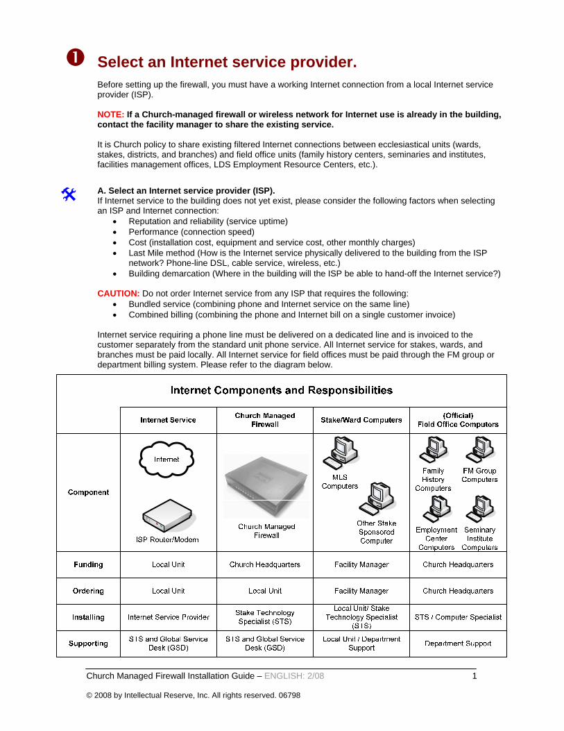
Internet service requiring a phone line must be delivered on a dedicated line and is invoiced to the customer separately from the standard unit phone service. All Internet service for stakes, wards, and branches must be paid locally. All Internet service for field offices must be paid through the FM group or department billing system. Please refer to the diagram below.
Church Managed Firewall Installation Guide – ENGLISH: 2/08 2 © 2008 by Intellectual Reserve, Inc. All rights reserved. 06798
Gather installation information.
A. Record your configuration and contact information in the tables below. In order to properly configure your network and to activate the firewall, you need to first gather the information listed below. Consult the person who ordered the Internet service or the Internet service provider (ISP) for details. NOTE: Before setting up the firewall, you must have a working Internet connection from a local ISP.
ISP Assigned Settings: If the ISP assigns a static IP or PPPoE authentication setting, complete the corresponding table below for step 6 of this guide. Skip these tables and step 6 if a dynamic IP is assigned by the ISP.
Church Unit and Local Support Contact
Unit number or property number
Unit name
Local support contact name
Support contact phone number
Support contact e-mail address
Internet Connection
Internet service provider (ISP) name
ISP technical support phone number
ISP account number
Connection type(for example, DSL, cable, wireless, etc.)
Connection speed (download / upload)(for example, 1.5Mbps/768k) /
ISP assigned settings(Dynamic IP, Static IP, or PPPoE)
If connection requires a static IP address
IP address
Subnet mask
Default gateway
Primary DNS
Secondary DNS
If connection requires a PPPoE profile on thefirewall. No required if PPPoE settings are only on the ISP router.
User name / password
PPPoE authentication (PAP, CHAP, MSCHAP)
Church Managed Firewall Installation Guide – ENGLISH: 2/08 3 © 2008 by Intellectual Reserve, Inc. All rights reserved. 06798
Identify all the parts.
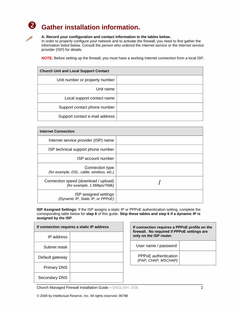
A. Unpack the equipment and confirm that you have each part.If you discover that any of the parts are missing, please call toll free 800-537-5971 with your name, contact information, unit number, and a description of what is missing.
Church-Managed Firewall Picture courtesy of Cisco Systems, Inc. Unauthorized use not permitted.This packages includes:
Cisco ASA 5505 firewall AC/DC power supply (connects to firewall) Power cable (connects supply to wall outlet) Yellow Ethernet network cables (2) Console Cable (light blue)
Support Documentation Cisco Documentation CD Installation Guide (this document)
B. Record the firewall information.Locate and record the following information from the sticker on the top or bottom of the firewall.
Firewall Information
Serial number (SN: XXXXXXXXXXX)
Firewall IP address (IP: X.X.X.X)
NOTE: Please keep and store all items that are shipped with this package for future support use.
Church Managed Firewall Installation Guide – ENGLISH: 2/08 4 © 2008 by Intellectual Reserve, Inc. All rights reserved. 06798
Prepare the computer(s). If you will be using this Internet connection for any computers that run the Church's Membership and
Leader Services (MLS) program, you must update the machine with the latest security patches and desktop software necessary for secure Internet use.
A. Install the required desktop security software. All computers that are provided by Church headquarters and its departments must be running the latest desktop image. MLS Computers Go to: http://mls.lds.org Enter the stake or ward unit # (for example, 12345) in the Username field and enter the password. This site contains the following required software for download:
MLS latest release Local Unit Security Software
Other Church-Provided Computers Contact the sponsoring department support group. Donated Computers Contact the sponsoring department support group.
B. Ensure that the computers have a network interface card (NIC).Make certain that each computer that will connect to the network has a network card to connect to the Church-managed firewall. The network card adapter is usually on the back of the computer: look for a square port large enough to connect the yellow Ethernet cable that came in the Church-managed firewall box. A wireless network card can also be used if there will be a secure wireless network in the building connected to the Church-managed firewall. Local units are responsible for all NIC devices, cabling, or secure wireless networks.
Church Managed Firewall Installation Guide – ENGLISH: 2/08 5 © 2008 by Intellectual Reserve, Inc. All rights reserved. 06798
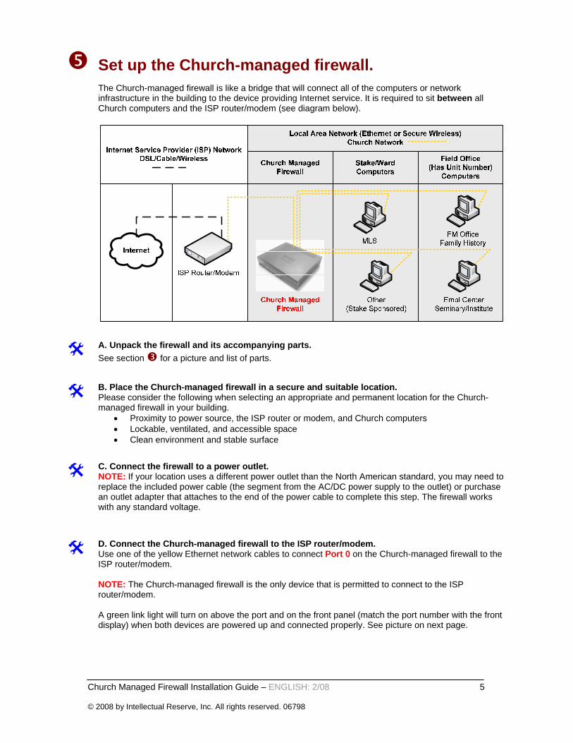
Set up the Church-managed firewall.
The Church-managed firewall is like a bridge that will connect all of the computers or network infrastructure in the building to the device providing Internet service. It is required to sit between all Church computers and the ISP router/modem (see diagram below).
A. Unpack the firewall and its accompanying parts.See section for a picture and list of parts.
B. Place the Church-managed firewall in a secure and suitable location.Please consider the following when selecting an appropriate and permanent location for the Church-managed firewall in your building.
• Proximity to power source, the ISP router or modem, and Church computers • Lockable, ventilated, and accessible space • Clean environment and stable surface
C. Connect the firewall to a power outlet.NOTE: If your location uses a different power outlet than the North American standard, you may need to replace the included power cable (the segment from the AC/DC power supply to the outlet) or purchase an outlet adapter that attaches to the end of the power cable to complete this step. The firewall works with any standard voltage.
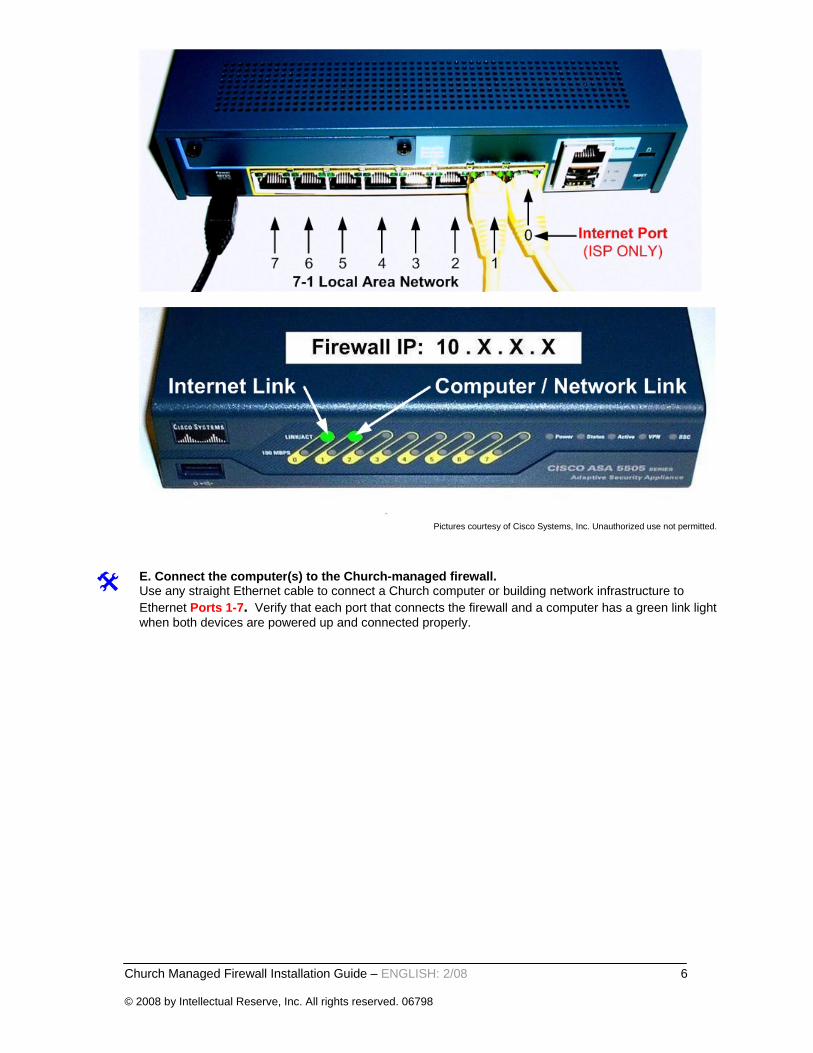
D. Connect the Church-managed firewall to the ISP router/modem.Use one of the yellow Ethernet network cables to connect Port 0 on the Church-managed firewall to the ISP router/modem. NOTE: The Church-managed firewall is the only device that is permitted to connect to the ISP router/modem. A green link light will turn on above the port and on the front panel (match the port number with the front display) when both devices are powered up and connected properly. See picture on next page.
Church Managed Firewall Installation Guide – ENGLISH: 2/08 6 © 2008 by Intellectual Reserve, Inc. All rights reserved. 06798
Pictures courtesy of Cisco Systems, Inc. Unauthorized use not permitted.
E. Connect the computer(s) to the Church-managed firewall.Use any straight Ethernet cable to connect a Church computer or building network infrastructure to Ethernet Ports 1-7. Verify that each port that connects the firewall and a computer has a green link light when both devices are powered up and connected properly.
Church Managed Firewall Installation Guide – ENGLISH: 2/08 7 © 2008 by Intellectual Reserve, Inc. All rights reserved. 06798
ISP-assigned static IP or PPPoE settings. (Skip this section if the ISP assigns a dynamic IP address.)
Some sites may require manual configuration changes on the Church-managed firewall in order to connect to the Internet via the ISP router or modem. Static IP or PPPoE assigned settings will need to be recorded in section of this installation guide. NOTE: Only make changes on the Church-managed firewall as outlined in this section. If any other changes are made, this device will not work as designed. Follow these steps to open the command line for administration using the console port on the ASA 5505. To do so, connect a PC to the firewall console port and run a serial terminal emulator on the PC or laptop.
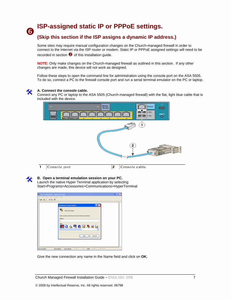
A. Connect the console cable. Connect any PC or laptop to the ASA 5505 (Church-managed firewall) with the flat, light blue cable that is included with the device.
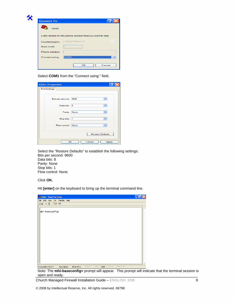
B. Open a terminal emulation session on your PC.Launch the native Hyper Terminal application by selecting Start>Programs>Accessories>Communications>HyperTerminal
Give the new connection any name in the Name field and click on OK.
Church Managed Firewall Installation Guide – ENGLISH: 2/08 8 © 2008 by Intellectual Reserve, Inc. All rights reserved. 06798
Select COM1 from the “Connect using:” field.
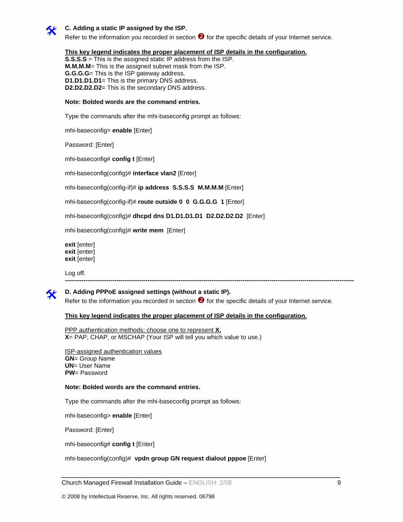
Select the “Restore Defaults” to establish the following settings: Bits per second: 9600 Data bits: 8 Parity: None Stop bits: 1 Flow control: None Click OK. Hit [enter] on the keyboard to bring up the terminal command line.
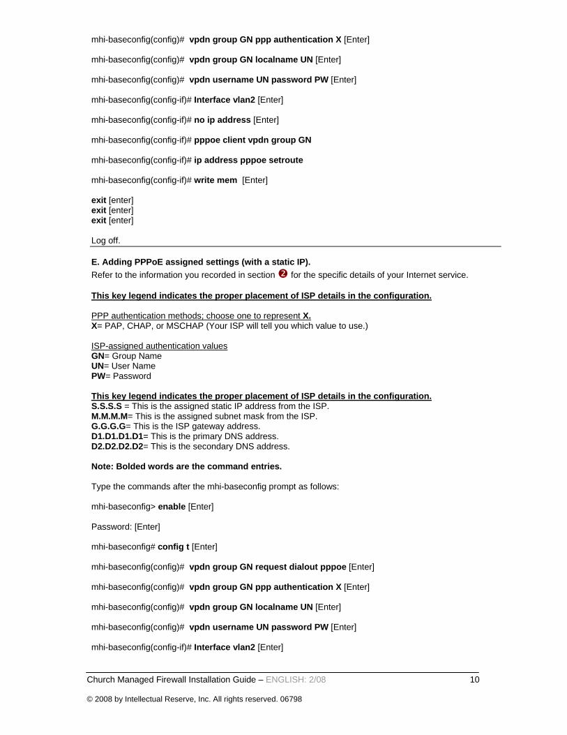
Note: The mhi-baseconfig> prompt will appear. This prompt will indicate that the terminal session is open and ready.
Church Managed Firewall Installation Guide – ENGLISH: 2/08 9 © 2008 by Intellectual Reserve, Inc. All rights reserved. 06798
C. Adding a static IP assigned by the ISP.Refer to the information you recorded in section for the specific details of your Internet service. This key legend indicates the proper placement of ISP details in the configuration. S.S.S.S = This is the assigned static IP address from the ISP. M.M.M.M= This is the assigned subnet mask from the ISP. G.G.G.G= This is the ISP gateway address. D1.D1.D1.D1= This is the primary DNS address. D2.D2.D2.D2= This is the secondary DNS address. Note: Bolded words are the command entries. Type the commands after the mhi-baseconfig prompt as follows: mhi-baseconfig> enable [Enter] Password: [Enter] mhi-baseconfig# config t [Enter] mhi-baseconfig(config)# interface vlan2 [Enter] mhi-baseconfig(config-if)# ip address S.S.S.S M.M.M.M [Enter] mhi-baseconfig(config-if)# route outside 0 0 G.G.G.G 1 [Enter] mhi-baseconfig(config)# dhcpd dns D1.D1.D1.D1 D2.D2.D2.D2 [Enter] mhi-baseconfig(config)# write mem [Enter] exit [enter] exit [enter] exit [enter] Log off. --------------------------------------------------------------------------------------------------------------------------------------------
D. Adding PPPoE assigned settings (without a static IP). Refer to the information you recorded in section for the specific details of your Internet service. This key legend indicates the proper placement of ISP details in the configuration. PPP authentication methods; choose one to represent X. X= PAP, CHAP, or MSCHAP (Your ISP will tell you which value to use.) ISP-assigned authentication values GN= Group Name UN= User Name PW= Password Note: Bolded words are the command entries. Type the commands after the mhi-baseconfig prompt as follows: mhi-baseconfig> enable [Enter] Password: [Enter] mhi-baseconfig# config t [Enter] mhi-baseconfig(config)# vpdn group GN request dialout pppoe [Enter]
Church Managed Firewall Installation Guide – ENGLISH: 2/08 10 © 2008 by Intellectual Reserve, Inc. All rights reserved. 06798
mhi-baseconfig(config)# vpdn group GN ppp authentication X [Enter] mhi-baseconfig(config)# vpdn group GN localname UN [Enter] mhi-baseconfig(config)# vpdn username UN password PW [Enter] mhi-baseconfig(config-if)# Interface vlan2 [Enter] mhi-baseconfig(config-if)# no ip address [Enter] mhi-baseconfig(config-if)# pppoe client vpdn group GN mhi-baseconfig(config-if)# ip address pppoe setroute mhi-baseconfig(config-if)# write mem [Enter] exit [enter] exit [enter] exit [enter] Log off. E. Adding PPPoE assigned settings (with a static IP). Refer to the information you recorded in section for the specific details of your Internet service. This key legend indicates the proper placement of ISP details in the configuration. PPP authentication methods; choose one to represent X. X= PAP, CHAP, or MSCHAP (Your ISP will tell you which value to use.) ISP-assigned authentication values GN= Group Name UN= User Name PW= Password This key legend indicates the proper placement of ISP details in the configuration. S.S.S.S = This is the assigned static IP address from the ISP. M.M.M.M= This is the assigned subnet mask from the ISP. G.G.G.G= This is the ISP gateway address. D1.D1.D1.D1= This is the primary DNS address. D2.D2.D2.D2= This is the secondary DNS address. Note: Bolded words are the command entries. Type the commands after the mhi-baseconfig prompt as follows: mhi-baseconfig> enable [Enter] Password: [Enter] mhi-baseconfig# config t [Enter] mhi-baseconfig(config)# vpdn group GN request dialout pppoe [Enter] mhi-baseconfig(config)# vpdn group GN ppp authentication X [Enter] mhi-baseconfig(config)# vpdn group GN localname UN [Enter] mhi-baseconfig(config)# vpdn username UN password PW [Enter] mhi-baseconfig(config-if)# Interface vlan2 [Enter]
Church Managed Firewall Installation Guide – ENGLISH: 2/08 11 © 2008 by Intellectual Reserve, Inc. All rights reserved. 06798
mhi-baseconfig(config-if)# no ip address [Enter] mhi-baseconfig(config-if)# pppoe client vpdn group GN mhi-baseconfig(config-if)# ip address S.S.S.S M.M.M.M pppoe [Enter] mhi-baseconfig(config-if)# route outside 0 0 G.G.G.G 1 [Enter] mhi-baseconfig(config)# dhcpd dns D1.D1.D1.D1 D2.D2.D2.D2 [Enter] mhi-baseconfig(config-if)# write mem [Enter] exit [enter] exit [enter] exit [enter] Log off. Note: The console cable can now be unplugged and stored nearby for future use. At this point the firewall device should be connected to the ISP router or modem. Proceed to section for additional steps before “activation.” If the commands above do not load, or if you have trouble understanding the procedure, please stop here and call the Global Service Desk for assistance. Try one of these toll-free numbers:
+1-866-678-2763 (North America) +800-2950-2950 (Europe and Africa)
Church Managed Firewall Installation Guide – ENGLISH: 2/08 12 © 2008 by Intellectual Reserve, Inc. All rights reserved. 06798
Activate the Church-managed firewall.
Once the Church-managed firewall is in place and connected to the ISP router/modem and a computer, you can proceed to activate the firewall for the site network.
A. Verify that you have recorded all the installation details.Make sure you have completely filled out the tables in section and section of this document. You will need to give this information to the Church Global Service Center (GSC) over the phone to register the device to your unit and allow the GSC to finalize the firewall configuration.
B. Confirm that the Church-managed firewall is properly connected to the ISP router/modem.Make sure that the Church-managed firewall and the ISP router/modem have power. If the two devices are on and connected properly by the yellow Ethernet cable, you should see a green light on in the top-left corner of Port 0 where the Ethernet cable from the ISP router/modem plugs into the firewall. The front display of the firewall will also indicate when a proper link is up with the ISP router/modem by displaying a lit green light on the LINK/ACT LED on Port 0.
C. Confirm that the Church-managed firewall is properly connected to a computer. Make sure you have at least one computer powered on and connected by an Ethernet cable to the Church-managed firewall. Check again to see that the port where the cable connects to the firewall (in any of ports 1-7) has a green link light on.
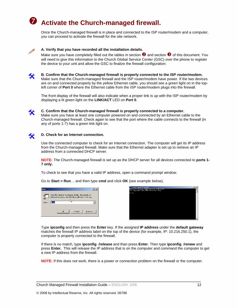
D. Check for an Internet connection. Use the connected computer to check for an Internet connection. The computer will get its IP address from the Church-managed firewall. Make sure that the Ethernet adapter is set up to retrieve an IP address from a connected DHCP server. NOTE: The Church-managed firewall is set up as the DHCP server for all devices connected to ports 1-7 only. To check to see that you have a valid IP address, open a command prompt window. Go to Start > Run… and then type cmd and click OK (see example below).
Type ipconfig and then press the Enter key. If the assigned IP address under the default gateway matches the firewall IP address label on the top of the device (for example, IP: 10.216.250.1), the computer is properly connected to the firewall. If there is no match, type ipconfig /release and than press Enter. Then type ipconfig /renew and press Enter. This will release the IP address that is on the computer and command the computer to get a new IP address from the firewall. NOTE: If this does not work, there is a power or connection problem on the firewall or the computer.

Church Managed Firewall Installation Guide – ENGLISH: 2/08 13 © 2008 by Intellectual Reserve, Inc. All rights reserved. 06798
E. Prepare the Web browser. Open the Internet browser and make sure that any proxy server settings are disabled on the Internet browser. In Internet Explorer, this is found under Tools > Internet Options > Connections. Click the LAN settings button and remove the check mark from "Use a proxy server for your LAN". Type www.google.com in the browser to attempt to connect to the Internet. Your Internet browser will redirect to the Internet Activation page. If you see this page, it means the firewall is connected properly and ready for Internet activation. This page will display a confirmation that the firewall is properly connected to the Internet and is ready for activation. Please follow the instructions on the displayed page on your Web browser.
F. Call the Global Service Center (GSC) to activate the firewall.Try one of these toll-free numbers:
+1-866-678-2763 (North America) +800-2950-2950 (Europe and Africa)
NOTE: If you cannot dial one of these numbers, please phone your area office and have them transfer your call to the Global Service Center. For additional information, go to www.lds.org and find the Clerk and Technology Support page under Serving in the Church > Melchizedek Priesthood.
Notes: