installing the superstack ii netbuilder ethernet...
TRANSCRIPT

SS2EthHWBook Page i Wednesday, April 30, 1997 5:26 PM
®
Installing the SuperStack® II NETBuilder® Ethernet Bridge/Router
http://www.3com.com/
Models 22x and 42x
Part No. 09-0850-003Published May 1997

SS2EthHWBook Page ii Wednesday, April 30, 1997 5:26 PM
3Com Corporation5400 Bayfront Plaza Santa Clara, California 95052-8145
Copyright © 3Com Corporation, 1997. All rights reserved. No part of this documentation may be reproduced in any form or by any means or used to make any derivative work (such as translation, transformation, or adaptation) without permission from 3Com Corporation.
3Com Corporation reserves the right to revise this documentation and to make changes in content from time to time without obligation on the part of 3Com Corporation to provide notification of such revision or change.
3Com Corporation provides this documentation without warranty of any kind, either implied or expressed, including, but not limited to, the implied warranties of merchantability and fitness for a particular purpose. 3Com may make improvements or changes in the product(s) and/or the program(s) described in this documentation at any time.
UNITED STATES GOVERNMENT LEGENDS:If you are a United States government agency, then this documentation and the software described herein are provided to you subject to the following restricted rights:
For units of the Department of Defense:Restricted Rights Legend: Use, duplication, or disclosure by the Government is subject to restrictions as set forth in subparagraph (c) (1) (ii) for Restricted Rights in Technical Data and Computer Software Clause at 48 C.F.R. 52.227-7013. 3Com Corporation, 5400 Bayfront Plaza, Santa Clara, California 95052-8145.
For civilian agencies:Restricted Rights Legend: Use, reproduction, or disclosure is subject to restrictions set forth in subparagraph (a) through (d) of the Commercial Computer Software - Restricted Rights Clause at 48 C.F.R. 52.227-19 and the limitations set forth in 3Com Corporation’s standard commercial agreement for the software. Unpublished rights reserved under the copyright laws of the United States.
If there is any software on removable media described in this documentation, it is furnished under a license agreement included with the product as a separate document, in the hard copy documentation, or on the removable media in a directory file named LICENSE.TXT. If you are unable to locate a copy, please contact 3Com and a copy will be provided to you.
Unless otherwise indicated, 3Com registered trademarks are registered in the United States and may or may not be registered in other countries.
3Com, NETBuilder, and SuperStack are registered trademarks of 3Com Corporation. 3TECH is a trademark of 3Com Corporation. 3ComFacts is a service mark of 3Com Corporation.
CompuServe is a registered trademark of CompuServe, Inc. IBM is a registered trademark of International Business Machines Corporation. AppleTalk is a registered trademark of Apple Corporation. Banyan and VINES are registered trademarks of Banyan Systems. UNIX is a registered trademark in the United States and other countries, licensed exclusively through X/Open Company Limited. XNS is a trademark of Xerox Corporation. Siemens and EWSD are registered trademarks of Siemens Aktiengesellschaft. AT&T and 5ESS are registered trademarks of American Telephone and Telegraph. DMS is a registered trademark of Nothern Telecom Limited.
Other brand and product names may be registered trademarks or trademarks of their respective holders.
Guide written by Ramona Boersma. Edited by Amy Guzules. Technical illustration by Debra Knodel. Production by Ramona Boersma.
The network connector RS-449 and the ISDN cable are TNV connection points as defined by EN 41 003. The ports 10 Base T, AUI, Console, V.35, and RS-232 are SELV ports as defined by EN 41 003.
Electromagnetic Compatibility InformationClassesVarious national agencies (in the United States, The Federal Communications Commission (FCC)) govern the levels of electromagnetic emissions from digital devices. Electromagnetic emissions can interfere with radio and television transmission. To reduce the risk of harmful interference these agencies have established requirements for manufacturers of digital devices
The manufacturer of a digital device must test and label a product to inform an end-user of the maximum emission level from the product when used in accordance with its instructions. The emission levels encountered are classified as Class A or Class B. A system that meets the Class A requirement can be marketed for use in an industrial or a commercial area. A system that meets the more stringent Class B requirement can be marketed for use in a residential area in addition to an industrial or a commercial area.
The end user is generally held responsible for ensuring that his system is suitable for its environment as stated in the above paragraph and bears the financial responsibility for correcting any harmful interference.
ii

SS2EthHWBook Page iii Wednesday, April 30, 1997 5:26 PM
ModificationsModifications or changes made to this device, and not approved by 3Com, may void the authority granted by the FCC, or other such agency, to operate this equipment.
Shielded CablesConnections between 3Com equipment and other equipment and peripherals must be made using shielded cables in order to maintain compliance with FCC, and other agency, electromagnetic frequency emissions limits. This statement does not apply to the ISDN cable or 10BASE-T cables.
Federal Communications Commission NoticeThis equipment has been tested and found to comply with the limits for a Class A digital device, pursuant to Part 15 of the FCC rules. These limits are designed to provide reasonable protection against harmful interference when the equipment is operated in a commercial environment. This equipment generates, uses and can create radio frequency energy and, if not installed and used inaccordance with the instruction manual, may cause harmful interference to radio communications. Operation of this equipment in a residential area can cause harmful interference in which case the user will be required to correct the interference at his own expense.
Canadian NoticeThis digital apparatus does not exceed the Class A limits for radio noise emissions from digital apparatus set out in the interference-causing equipment standard entitled “Digital Apparatus,” ICES-003 of the Department of Communications.
Avis CanadienCet appareil numérique respecte les limites bruits radioélectriques applicables aux appareils numériques de Classe A prescrites dans la norme sur le matériel brouilleur: “Appareils Numériques”, NMB-003 édictée par le ministre des Communications.
Japanese Notice
Type Approval InformationThis apparatus has been approved for use for connection to the following public telecommunication services: ISDN basic access, X.25 (V.24, V.36, and X.21), X.21 leased lines, X.21bis leased lines (V.24 and V.36). Any other usage will invalidate the approval of the apparatus if as a result it then ceases to conform against the standards against which approval was granted.
NoticeThe Industry Canada label identifies certified equipment. This certification means that the equipment meets certain telecommunications network protective, operational, and safety requirements. The Department does not guarantee the equipment will operate to the users’ satisfaction.
Before installing this equipment, users should ensure that it is permissible to be connected to the facilities of the local telecommunications company. The equipment must also be installed using an acceptable method of connection. In some cases, the inside wiring associated with a single line individual service may be extended by means of a certified connector assembly. The customer should be aware that compliance with the above conditions may not prevent degradation of service in some situations.
Repairs to certified equipment should be made by an authorized Canadian maintenance facility designated by the supplier. Any repairs or alterations made by the user to this equipment, or equipment malfunctions, may give the telecommunications company cause to request the user to disconnect the equipment.
Users should ensure for their own protection that the electrical ground connections of the power utility, telephone lines, and internal metallic water pipe system, if present, are connected together. This precaution may be particularly important in rural areas.
CAUTION: Users should not attempt to make electrical ground connections by themselves, but should contact the appropriate inspection authority or an electrician, as appropriate.
iii

SS2EthHWBook Page iv Wednesday, April 30, 1997 5:26 PM
CE NoticeMarking by the following symbol indicates compliance of this equipment with the EMC and Telecom Directives of the European Community. Such marking is indicative that this equipment meets or exceeds the following technical standards:
■ EN 55022 — Limits and methods of measurement of radio interference characteristics of information technology equipment.
■ EN 50082-1 — Electromagnetic compatibility – generic immunity standard part 1: residential, commercial, and light industrial.
■ I-CTR2 — For connection to X.25 packet switched services and X.21 leased lines.
■ I-CTR3 — For models with ISDN interfaces: connection to basic rate ISDN services.
iv

SS2EthHWBook Page v Wednesday, April 30, 1997 5:26 PM
CONTENTS
ABOUT THIS GUIDE
Conventions 1
1 INSTALLING THE HARDWARE
Required Equipment 1-1Mounting 1-2
Rack-Mount Kit 1-2Installing on a Tabletop 1-2Stacking with Brackets 1-3Installing in a Rack 1-3
Cabling the Connectors 1-4Cabling the LAN Connector 1-4Cabling the ISDN Connector (Models 42x) 1-5Cabling the Serial Connectors 1-6
Models 22x 1-6Models 42x 1-6
Attaching a Redundant Power System 1-7Connecting a PC, Terminal, or Modem 1-8Shutting Down 1-9
2 OVERVIEW
Model Features 2-1Chassis Panels 2-2LEDs 2-4Hardware Interrupt Switch 2-4Connectors and Cables 2-4
Console Cables 2-4PC Cable 2-5Terminal Cable 2-6Modem Cable 2-7
v

SS2EthHWBook Page vi Wednesday, April 30, 1997 5:26 PM
LAN Connectors and Cables 2-7AUI Connector and Cable 2-710 Base T Connector and Cable 2-8Cabling Standards 2-9
Serial Cables 2-10V.35 Straight-Through Cable (22x) 2-10RS-449 Straight-Through Cable 2-11RS-232 Straight-Through Cable 2-12RS-449 to RS-530 Conversion Cable 2-13V.36/RS-449 to V.35 Adapter Cable (Model 42x) 2-14V.36/RS-449 to V.36 Adapter Cable (Model 42x) 2-15RS-449 to X.21 Adapter Cable 2-16
ISDN Cable (Model 42x ) 2-17Physical Specifications 2-18
3 UPGRADING MEMORY
Removing the Cover 3-1Installing Flash Memory 3-2Installing DRAM 3-4Reinstalling the Cover 3-4
4 TROUBLESHOOTING
Troubleshooting During the Test Phase 4-2Troubleshooting During the Load Phase 4-2LED Meanings 4-3
A PROVISIONING YOUR ISDN LINE
Ordering North American ISDN BRI Services A-1North American Switch Provisioning Tables A-3
AT&T 5ESS Switch A-4AT&T 5ESS Custom Switch A-5DMS 100 and National ISDN A-6Siemens EWSD Switch A-7
SPIDs A-7NT1s and Power Supplies A-8Ordering German ISDN BRI Services A-9
vi

SS2EthHWBook Page vii Wednesday, April 30, 1997 5:26 PM
B TECHNICAL SUPPORT
Online Technical Services B-1World Wide Web Site B-13Com Bulletin Board Service B-1
Access by Analog Modem B-2Access by Digital Modem B-2
3ComFacts Automated Fax Service B-23ComForum on CompuServe Online Service B-3
Support from Your Network Supplier B-3Support from 3Com B-4Returning Products for Repair B-5
INDEX
3COM CORPORATION LIFETIME LIMITED WARRANTY
vii

SS2EthHWBook Page viii Wednesday, April 30, 1997 5:26 PM
viii

SS2EthHWBook Page 1 Wednesday, April 30, 1997 5:26 PM
ABOUT THIS GUIDE
This guide includes complete hardware installation and cabling information for your SuperStack® II NETBuilder® bridge/router model 22x or 42x.
This guide is for the following audience:
■ Inexperienced end users configuring their first internetworking device
■ Experienced network administrators who are configuring the central node as well as the peripheral node (boundary router)
■ Experienced system integrators
If the information in the release notes shipped with your product differs from the information in this guide, follow the release notes.
Conventions Table 1 provides a list notice icons that are used throughout this guide.
Table 1 Notice Icons
Icon Notice Type Alerts you to...
Information note Important features or instructions
Caution Risk of personal safety, system damage, or loss of data
Warning Risk of severe personal injury

2
C
HAPTER
: A
BOUT
T
HIS
G
UIDE
SS2EthHWBook Page 2 Wednesday, April 30, 1997 5:26 PM

SS2EthHWBook Page 1 Wednesday, April 30, 1997 5:26 PM
1
INSTALLING THE HARDWAREThis chapter describes how to install your SuperStack II NETBuilder bridge/router.
Required Equipment
Table 1-1 lists the items you receive in the shipping carton and items you need to provide.
* The software is preinstalled in the flash memory drive of the bridge/router and automatically loads when you turn on thepower. The software CD-ROM is for software recovery purposes only.
Table 1-1 Equipment Received and Equipment Needed
Shipping carton contents SuperStack II NETBuilder bridge/router
Power cable
Rack-mount kit
Software CD-ROM* (models 222, 224, 227, 228, 422, 424, and 427 only)
Documentation and documentation CD-ROM
NETBuilder Upgrade Utilities CD-ROM (models 222, 224, 227, 228, 422, 424, and 427 only)
What you need to provide
Channel service unit/digital service unit (CSU/DSU) device or modem for all wide area ports except Integrated Services Digital Network (ISDN)
10BASE-T or AUI network cable
V.35, RS-449, or RS-232 cable
ISDN cable (42x models only)
V.35 adapter cable (42x models only. 3Com® part number 3C8035)
V.36 adapter cable (42x models only. Not supplied by 3Com)
X.21 adapter cable (3Com part number 3C8021)
A cable (3Com part number 3C8101) to connect to a SuperStack II Redundant Power System (RPS).
Terminal, PC, or modem and cable

1-2
C
HAPTER
1: I
NSTALLING
THE
H
ARDWARE
SS2EthHWBook Page 2 Wednesday, April 30, 1997 5:26 PM
WARNING: To eliminate cable noise emission in excess of FCC regulations, part 15, subpart J, and EN55022B, all interconnection cables should be equipped with shielded connectors, the backshells of which must completely surround the cable shield.
For more information on cables, refer to Chapter 2.
Mounting You can mount your bridge/router on a tabletop, stack it, or mount it in a rack.
Rack-Mount Kit The rack-mount kit contains the following hardware:
Figure 1-1 Rack-Mount Kit Contents
Installing on aTabletop
If you plan to install your bridge/router on a tabletop, attach the rubber feet as shown.
Two rack-mount brackets Two stacking brackets
Four M4x8 mm Phillipspanhead screws for usewith stacking brackets
Six M4x10 mm Phillips flatheadmachine screws for use
with rack-mount brackets
Four adhesive-backedrubber feet
Attach feet to cornersof chassis bottom
Flex plastic sheet untilfeet pop loose

Mounting 1-3
SS2EthHWBook Page 3 Wednesday, April 30, 1997 5:26 PM
Stacking withBrackets
The stacking brackets can be used to securely stack several bridge/routers on a tabletop. Use the stacking brackets and the M4x8 mm panhead stacking screws shown in Figure 1-1.
Installing in a Rack To install the bridge/router in a rack, use the rack-mount brackets and the M4x10 mm flathead rack-mount screws shown in Figure 1-1 and follow these steps:
1 Secure the rack-mount brackets to each side of the chassis using three flathead screws per bracket.
Bottom bracket acts as a support
Attach brackets as shownto lock two units together
Place screws in holes as shown

1-4 CHAPTER 1: INSTALLING THE HARDWARE
SS2EthHWBook Page 4 Wednesday, April 30, 1997 5:26 PM
2 Hold the chassis between the poles of the rack and attach the brackets to the rack using panhead screws (you must provide these screws). Tighten each screw securely.
CAUTION: Using fewer than two screws to secure the brackets to the rack may cause the boundary router to fall and sustain damage not covered by the warranty.
Cabling the Connectors
This section describes how to cable the LAN, ISDN, and serial connectors on your bridge/router.
If you are planning to connect your SuperStack II bridge/router directly to another SuperStack II system or to a NETBuilder II® bridge/router with an HSS V.35 3-port module installed, you must use a modem eliminator between the two devices. Be sure the default setting of External for the -PATH CLock parameter is maintained on each device. Contact your 3Com supplier for a list of suggested modem eliminators.
Cabling the LANConnector
You can use only one type of LAN connector on each bridge/router. The following figure shows how to cable a LAN connector.
For more information on AUI and 10BASE-T cables, refer to Chapter 2.
Send
Active
Fault
Link
10BT
+/-
10 Base T AUILAN
10BASE-Tcable
ORAUIcable

Cabling the Connectors 1-5
SS2EthHWBook Page 5 Wednesday, April 30, 1997 5:26 PM
Cabling the ISDNConnector
(Models 42x)
This section applies to model 42x bridge/routers only. The following figure shows how to cable an ISDN connector.
The NT1 and power supply shown in the figure above must either be leased from the telephone company or purchased from an ISDN equipment vendor in the U.S. and Canada only. In other countries, you do not need to provide this equipment because the function of the equipment is provided by the ISDN switch. For more information about ISDN, refer to Appendix A.
For more information on ISDN cables, refer to Chapter 2.
ISDN cable
Wall outlet
*required for U.S. and Canada only
Console S/T B1Link
LineAct
LineError
Connect
Fault
ISDNB2
Networktermination(nt1)/power
supply*

1-6 CHAPTER 1: INSTALLING THE HARDWARE
SS2EthHWBook Page 6 Wednesday, April 30, 1997 5:26 PM
Cabling the SerialConnectors
The following figures show how to cable the serial connectors.
Models 22x
Boundary router models 221 and 223 can use one serial port for main communication and an additional serial port for backup if the main port malfunctions.
Full router models 222, 224, 227, and 228 can use all three serial ports concurrently.
For more information on serial cables, refer to Chapter 2.
Models 42x
Only one serial port may be used at a time. Cabling more than one serial port may cause unpredictable results.
For more information on serial cables, refer to Chapter 2.
V.35cable
RS-232cable
SYSTEM
SuperStack IINETBuilder
Status
Run
Load
Test
Console
SERIAL
RS-449 (B)V.35 (A)
RS-232 (C)
A
Link
Active
FaultB C
RS-449, RS-530 adapter orX.21 adapter cables
RS-449V.35 adapterV.36 adapter
X.21 adapter orRS-530 adapter cables
RS-232cable
OR
SYSTEM
SuperStack IINETBuilder
Status
Run
Load
Test
SERIAL
V.36 (A) / RS-449 (B) RS-232 (C) A Link
Active
Fault
B
C

Attaching a Redundant Power System 1-7
SS2EthHWBook Page 7 Wednesday, April 30, 1997 5:26 PM
Attaching a Redundant Power System
You can attach your SuperStack II bridge/router to a SuperStack II Redundant Power System (RPS). You will need to order the connecting cable (part number 3C8101) from 3Com. The following figure shows where to attach this cable.
For full power supply redundancy, attach one end of the RPS cable to the rear panel on the bridge/router and the other end to the RPS. Then attach one end of the power cord to the rear panel on the bridge/router and the other end to a power outlet.
In this configuration, the internal supply provides power. If the internal supply fails or is switched off, or if there is a power failure, the RPS is activated and the bridge/router reboots.
To reset a bridge/router in this configuration, turn the power off, wait 5 seconds and turn it back on. The bridge/router switches to the RPS, then switches back to the internal supply to reboot.
CAUTION: For system susceptibility protection, always leave the AC cord attached to the bridge/router hardware and to a power outlet.
Internal power supply failure is rare. If it occurs, the power switch on your bridge/router will not operate. To reboot you will need to unplug the RPS cable and then plug it back in. Replace your bridge/router with another bridge/router that has a functioning internal power supply as soon as possible. Contact your 3Com representative to replace your bridge/router.
Rear panel of unit
Attach RPS cable here

1-8 CHAPTER 1: INSTALLING THE HARDWARE
SS2EthHWBook Page 8 Wednesday, April 30, 1997 5:26 PM
Connecting a PC, Terminal, or Modem
Connect a PC running a terminal emulation program, a terminal, or a modem to the Console port on the SuperStack II bridge/router to configure the bridge/router software and review startup and system operation messages.
To connect a PC, terminal, or modem to the DPE module, follow these steps:
1 Obtain a cable to connect the console to the Console port on the bridge/router. See “Console Cables” on page 2-4 for cable pinouts.
The Console port is a 9-pin male connector.
For the PC, use a 9-pin female to 9-pin female PC cable. A null modem-type cable may be used.
For the terminal, use a 9-pin female to 25-pin terminal cable. A null modem-type cable may be used.
For the modem, use a 9-pin female to 25-pin male modem cable. A straight-through-type cable may be used.
2 Connect one end of the cable to the Console port on the SuperStack II system and the other end to the serial port on the back of your console.
3 Verify that configurable parameters of your console match the configuration settings of the Console port specified in Table 1-2.
4 Turn on the console.
Table 1-2 CONSOLE Port Configuration Settings
Characteristic Setting
Baud rate 9600
Databits 8
Parity None
Stop bits 1
DTR Ignored
Duplex Full
Echo Off
Flow control X-on/X-off

Shutting Down 1-9
SS2EthHWBook Page 9 Wednesday, April 30, 1997 5:26 PM
Shutting Down If your SuperStack II system is not connected to an RPS, turn off the power by pressing the off (0) side of the power switch on the back panel. If your system is connected to an RPS, turn off the power by unplugging the RPS cable from the system and then pressing the off (0) side of the power switch.

1-10 CHAPTER 1: INSTALLING THE HARDWARE
SS2EthHWBook Page 10 Wednesday, April 30, 1997 5:26 PM

SS2EthHWBook Page 1 Wednesday, April 30, 1997 5:26 PM
2
OVERVIEWThis chapter provides an overview of the SuperStack II NETBuilder bridge/router, including information on:
■ Model features
■ Chassis panels
■ LEDs
■ DIP switches
■ Hardware interrupt switch
■ Connectors and cables
■ Physical specifications
Model Features Table 2-1 lists each SuperStack II NETBuilder model along with memory, port, and upgrade information.
Table 2-1 SuperStack II NETBuilder Model Features
ModelFlash Memory DRAM LAN Ports
Active WAN Ports
Flash Memory Upgradeable To
DRAM Upgradeable To
Software Upgradeable
221 2 MB 4 MB 1 10BASE-T or AUI
1 serial
1 backup serial
6 MB 8 MB Yes
222 2 MB 4 MB 1 10BASE-T or AUI
3 serial 6 MB 8 MB Yes
223 4 MB 8 MB 1 10BASE-T or AUI
1 serial
1 backup serial
8 MB 12 MB Yes
224 2 MB 4 MB 1 10BASE-T or AUI
3 serial 6 MB 8 MB Yes
227 4 MB 8 MB 1 10BASE-T or AUI
3 serial 8 MB 12 MB Yes
228 4 MB 8 MB 1 10BASE-T or AUI
3 serial 8 MB 12 MB No
(continued)

2-2 CHAPTER 2: OVERVIEW
SS2EthHWBook Page 2 Wednesday, April 30, 1997 5:26 PM
Chassis Panels The following figures show the front and back panels for each chassis.
421 2 MB 4 MB 1 10BASE-T or AUI
1 ISDN BRI 6 MB 8 MB Yes
422 2 MB 4 MB 1 10BASE-T or AUI
1 ISDN BRI,
1 serial
6 MB 8 MB Yes
423 4 MB 8 MB 1 10BASE-T or AUI
1 ISDN BRI,
1 serial
8 MB 12 MB Yes
424 2 MB 4 MB 1 10BASE-T or AUI
1 ISDN BRI,
1 serial
6 MB 8 MB Yes
427 4 MB 8 MB 1 10BASE-T or AUI
1 ISDN BRI,
1 serial
8 MB 12 MB No
Table 2-1 SuperStack II NETBuilder Model Features (continued)
ModelFlash Memory DRAM LAN Ports
Active WAN Ports
Flash Memory Upgradeable To
DRAM Upgradeable To
Software Upgradeable

Chassis Panels
2-3
Figu
re 2-1 Chassis Front Panels
ower/ault
wer/ult
RunadstDs
Power/FaultLED
lt)
nadstDs
Power/FaultLED
SS2EthH
WB
ook Page 3 Wednesday, A
pril 30, 1997 5:26 PM
SYSTEM
SuperStack IINETBuilder
Status
Run
Load
Test
Console
SERIAL
RS-449 (B)V.35 (A)
RS-232 (C)Send
Active
Fault
Link
10BT
+/-
10 Base T AUILAN
A
Link
Active
FaultB C
SYSTEM
SuperStack IINETBuilder
Status
Run
Load
Test
Console
SERIAL
V.36 (A) / RS-449 (B) RS-232 (C)Send
Active
Fault
Link
10BT
+/-
10 Base T AUILAN
A Link
Active
Fault
B
C
S/T B1Link
LineAct
LineError
Connect
Fault
ISDNB2
Fwd PF
Fwd PoFa
Model 22x
Model 42x
Link10BT+/-LEDs
10 Base Tconnector
10 Base Tconnector
Consoleconnector
RS-449connector
V.36/RS-449connector
RS-232connector
RS-232connector
V.35connector
SendActiveFaultLEDs
LinkActiveFaultLEDs (A, B, and Cfor serial connectors)
LoTeLE
FwdLED
StatusLEDs
AUIconnector
Link10BT+/-LEDs
Consoleconnector
S/Tconnector
LineActLED
LineErrorLED
LinkConnectFaultLEDs (B1 and B2)
SendActiveFaultLEDs
LinkActiveFaultLEDs
ABCLEDs(serial connectorsfor Link, Active, and Fau
RuLoTeLE
FwdLED
StatusLEDs
AUIconnector
2-4 CHAPTER 2: OVERVIEW
SS2EthHWBook Page 4 Wednesday, April 30, 1997 5:26 PM
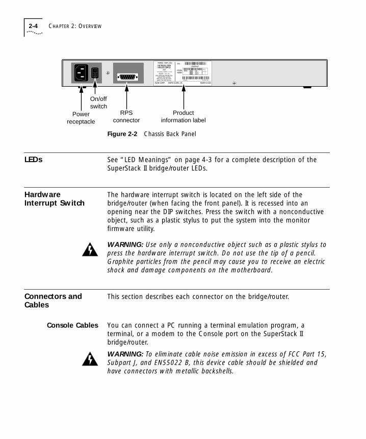
Figure 2-2 Chassis Back Panel
LEDs See “LED Meanings” on page 4-3 for a complete description of the SuperStack II bridge/router LEDs.
Hardware Interrupt Switch
The hardware interrupt switch is located on the left side of the bridge/router (when facing the front panel). It is recessed into an opening near the DIP switches. Press the switch with a nonconductive object, such as a plastic stylus to put the system into the monitor firmware utility.
WARNING: Use only a nonconductive object such as a plastic stylus to press the hardware interrupt switch. Do not use the tip of a pencil. Graphite particles from the pencil may cause you to receive an electric shock and damage components on the motherboard.
Connectors and Cables
This section describes each connector on the bridge/router.
Console Cables You can connect a PC running a terminal emulation program, a terminal, or a modem to the Console port on the SuperStack II bridge/router.
WARNING: To eliminate cable noise emission in excess of FCC Part 15, Subpart J, and EN55022 B, this device cable should be shielded and have connectors with metallic backshells.
Powerreceptacle
On/offswitch
MODEL: ESPL-310
REMOTE OFFICENETBUILDER
222
S/N:1SC05427
100-240VAC, 50/60HZ, 1.0-0.5A
250V, F2A
8.3
FOR CONTINUED PROTECTIONAGAINST FIRE HAZARD
REPLACE FUSE ONY WITHSAME TYPE AND RATING
NTWKADDR:
3COM CORP. SANTA CLARA, CA. MADE IN USA
080002 04BA1E LAN04BA1F04BA2004BA21
WAN-AWAN-BWAN-C
20-0261-00007/31/95
RPSconnector
Productinformation label

Connectors and Cables 2-5
SS2EthHWBook Page 5 Wednesday, April 30, 1997 5:26 PM
PC Cable
Figure 2-3 shows the pinouts for a 9-pin female to 9-pin female PC cable. A null modem-type cable may be used.
Figure 2-3 9-pin to 9-pin PC Cable (Null Modem-Type)
5 4 3 2 1
9 8 7 6
5 4 3 2 1
9 8 7 6
Name Abbr Pin Pin Abbr Name
9-pin female connector9-pin female connector
23187
546
327
81564
TxDRxDRTS
CTSCDGNDDSRDTR
RxDTxDCD
CTSRTS
GndDTRDSR
Transmit DataReceive DataRequest to Send
Clear to SendCarrier DetectSignal GroundData Set ReadyData Terminal Ready
Receive DataTransmit DataCarrier DetectClear to Send
Request to Send
Signal GroundData Terminal Ready
Data Set Ready
To Console port To PC serial port

2-6 CHAPTER 2: OVERVIEW
SS2EthHWBook Page 6 Wednesday, April 30, 1997 5:26 PM
Terminal Cable
Figure 2-4 shows the pinouts for a 9-pin female to 25-pin terminal cable. A null modem-type cable may be used.
Figure 2-4 9-pin to 25-pin Terminal Cable (Null Modem-Type)
1 2 3 4 5 6 7 8 9 10 11 12 13
14 15 16 17 18 19 20 21 22 23 24 25
5 4 3 2 1
9 8 7 6
Name Abbr Pin Pin Abbr Name
25-pin male or female connector9-pin female connector
23187
546
234
5876
20
TxDRxDRTS
CTSCDGNDDSRDTR
RxDTxDCD
CTSRTS
GNDDTRDSR
Transmit DataReceive DataRequest to Send
Clear to SendCarrier DetectSignal GroundData Set ReadyData Terminal Ready
Receive DataTransmit DataCarrier DetectClear to Send
Request to Send
Signal GroundData Terminal Ready
Data Set Ready
To Console port To terminal

Connectors and Cables 2-7
SS2EthHWBook Page 7 Wednesday, April 30, 1997 5:26 PM
Modem Cable
Figure 2-5 shows the pinouts for a 9-pin female to 25-pin male modem cable. A straight-through-type cable may be used.
Figure 2-5 9-pin to 25-pin Modem Cable (Straight-Through-Type)
LAN Connectors andCables
There are two Ethernet connectors on the bridge/router. Only one connector can be used at one time.
AUI Connector and Cable
The following figure shows the pinouts of the AUI connector (DB-15) used with 10BASE-5 Ethernet. The connector bodies connect the cable shield to chassis ground. Table 2-2 lists cable type and emissions classes compatible with the AUI connector.
1 2 3 4 5 6 7 8 9 10 11 12 13
14 15 16 17 18 19 20 21 22 23 24 25
5 4 3 2 1
9 8 7 6
25-pin male connector9-pin female connector
To Console port To modem
Name Abbr Pin Pin Abbr Name3248576
20
Receive DataTransmit DataRequest to SendCarrier DetectClear to SendSignal GroundData Set ReadyData Terminal Ready
RxDTxDRTSCDCTSGNDDSRDTR
TxDRxDRTSCD
CTSGNDDSRDTR
Transmit DataReceive Data
Request to SendCarrier DetectClear to SendSignal Ground
Data Set ReadyData Terminal Ready
32718564
5
12 11 10 915 14 13
4 38 7 6 2 1
AUI
DB-15 female (shielded)
1 Gnd2 Collision +3 TX+4 GND5 RX+6 GND7 N/A8 GND
9 Collision-10 TX-11 GND12 RX-13 +12V, .5A14 GND15 N/A

2-8 CHAPTER 2: OVERVIEW
SS2EthHWBook Page 8 Wednesday, April 30, 1997 5:26 PM
Auxiliary Power. Auxiliary +12 volt power is available on the AUI connector. To use the auxiliary power pins, follow the guidelines in Table 2-3.
3Com does not guarantee compatibility with external devices that use the auxiliary power pins of the AUI connector. Consult the manufacturer of external devices to ensure compliance with the maximum current allowed and to ensure the device does not compromise signalling.
10 Base T Connector and Cable
The following figure shows the pinouts of the 10 Base T connector (RJ-45). The connector bodies connect the cable shield to chassis ground. Table 2-4 lists cable types and emissions classes compatible with the 10 Base T connector.
* Shielding of all cable types should be terminated 360 degrees at the cable plug.
Table 2-2 AUI Cable Type and Emissions Compliance
Emissions Compliance*
Cable Type FCC and VCCI Class A EN55022 Class B
AUI (Transceiver)
78 ohm yes yes
Table 2-3 Auxiliary Pin Use
Pinout (AUI) Maximum Current
Pin 13 +12 volts (+/- 10%), 500 mA (fused at 1.0 A)
Pin 6 +12 volt ground return
12345 786
10 Base T
1 TX+2 TX-3 RX+6 RX-
RJ-45 female (shielded)

Connectors and Cables 2-9
SS2EthHWBook Page 9 Wednesday, April 30, 1997 5:26 PM
Cabling Standards
Cabling should be installed in accordance with the following standards:
■ EIA/ TIA-568 – Commercial building telecommunications wiring standard
■ TSB-36 – Additional cable specifications for unshielded twisted pair cables
■ IBM cabling guidelines
* Shielding of all cable types should be terminated 360 degrees at the cable plug.† All UTP compliance testing was accomplished using cables built with Stewart Connector
Co. connector, part number 940 SP-36-08-08.
Table 2-4 10BASE-T Cable Types and Emissions Compliance
Emissions Compliance*
Cable Type FCC and VCCI Class A EN55022 Class B
UTP† 100 ohm:
Category 3 yes no
Category 4 yes no
Category 5 yes no
Shielded TP† 100 ohm:
Category 3 yes yes
Category 4 yes yes
Category 5 yes yes

2-10 CHAPTER 2: OVERVIEW
SS2EthHWBook Page 10 Wednesday, April 30, 1997 5:26 PM
Serial Cables The following cables can be used with the serial port connectors.
V.35 Straight-Through Cable (22x)
This straight-through cable connects the V.35 port on a bridge/router to a standard V.35 DCE device.
Figure 2-6 V.35 Straight-Through Cable
3Com does not sell this cable.
BFLRVZDD
JJNN
DJNTXBB
FF
LL
CHMSWAEE
KK
AEKPUYCC
HH
MM
BFLRVZDD
JJNN
DJNTXBB
FF
LL
CHMSWAEE
KK
AEKPUYCC
HH
MM
Name Abbr Pin Pin Abbr Name
V.35 male connector V.35 male connector
To V.35 port on bridge/router To DCE
FG
SG
RTS
CTS
DSR
RLSD
DTR
SD+
RD+
SD-
RD-
SCTE+
SCR+
SCTE-
SCR-
SCT+
SCT-
FG
SG
RTS
CTS
DSR
RLSD
DTR
SD+
RD+
SD-
RD-
SCTE+
SCR+
SCTE-
SCR-
SCT+
SCT-
Frame Ground
Signal Ground
Request to Send
Clear to Sent
Data Set Ready
Receive Line Signal Detect
Data Terminal Ready
Send Data (A)
Receive Data (A)
Send Data
Received Data (B)
Serial clock Transmit External (A)
Serial Clock Receive (A)
Serial clock Transmit External (B)
Serial Clock Receive (B)
Serial Clock Transmit (A)
Serial Clock Transmit (B)
Frame Ground
Signal Ground
Request to Send
Clear to Sent
Data Set Ready
Receive Line Signal Detect
Data Terminal Ready
Send Data (A)
Receive Data (A)
Send Data
Received Data (B)
Serial Clock Transmit External (A)
Serial Clock Receive (A)
Serial Clock Transmit External (B)
Serial Clock Receive (B)
Serial Clock Transmit (A)
Serial Clock Transmit (B)
A
B
C
D
E
F
H
P
R
S
T
U
V
W
X
Y
AA
A
B
C
D
E
F
H
P
R
S
T
U
V
W
X
Y
AA

Connectors and Cables 2-11
SS2EthHWBook Page 11 Wednesday, April 30, 1997 5:26 PM
RS-449 Straight-Through Cable
This straight-through cable connects the RS-449 or V.36/RS-449 port on a SuperStack II bridge/router to a standard RS-449 DCE device.
Figure 2-7 RS-449 Straight-Through Cable
3Com does not sell this cable.
1 2 3 4 5 6 7 8 9 10 11 12 13 14 15 16 17 18 19
20 21 22 23 24 25 26 27 28 29 30 31 32 33 34 35 36 37
1 2 3 4 5 6 7 8 9 10 11 12 13 14 15 16 17 18 19
20 21 22 23 24 25 26 27 28 29 30 31 32 33 34 35 36 37
Name Abbr Pin Pin Abbr Name
37-pin female connector
To RS-449 port on bridge/router To CSU/DSU
37-pin female connector
Shield
Send Data
Send Data
Send Timing
Send Timing
Receive Data
Receive Data
Request to Send
Request to Send
Receive Timing
Receive Timing
Data Mode
Data Mode
Terminal Ready
Terminal Ready
Receive Ready
Receive Ready
Terminal Timing
Terminal Timing
Signal Ground
Shield
Send Data
Send Data
Send Timing
Send Timing
Receive Data
Receive Data
Request to Send
Request to Send
Receive Timing
Receive Timing
Data Mode
Data Mode
Terminal Ready
Terminal Ready
Receive Ready
Receive Ready
Terminal Timing
Terminal Timing
Signal Ground
Sheild
SD (B)
SD (A)
ST (B)
ST (A)
RD (B)
RD (A)
EIA (B)
EIA (A)
RT (B)
RT (A)
DM (B)
DM (A)
TR (B)
TR (A)
RR (B)
RR (A)
TT (B)
TT (A)
SG
Sheild
SD (B)
SD (A)
ST (B)
ST (A)
RD (B)
RD (A)
EIA (B)
EIA (A)
RT (B)
RT (A)
DM (B)
DM (A)
TR (B)
TR (A)
RR (B)
RR (A)
TT (B)
TT (A)
SG
1
22
4
23
5
24
6
25
7
26
8
29
11
30
12
31
13
35
17
19
1
22
4
23
5
24
6
25
7
26
8
29
11
30
12
31
13
35
17
19

2-12 CHAPTER 2: OVERVIEW
SS2EthHWBook Page 12 Wednesday, April 30, 1997 5:26 PM
RS-232 Straight-Through Cable
This straight-through cable connects the RS-232 port on a SuperStack II bridge/router to a standard RS-232 DCE device.
Figure 2-8 shows the pin assignments of the RS-232 cable.
Figure 2-8 RS-232 Straight-Through Cable
3Com does not sell this cable.
1 2 3 4 5 6 7 8 9 10 11 12 13
14 15 16 17 18 19 20 21 22 23 24 25
1 2 3 4 5 6 7 8 9 10 11 12 13
14 15 16 17 18 19 20 21 22 23 24 25
Name Abbr Pin Pin Abbr Name
25-pin male connector 25-pin male connector
Shield
Transmit Data
Receive Data
Request to Send
Clear to Send
DCE Ready
Signal Ground
Carrier Detect
Transmit Clock
Receive Clock
DTE Ready
Remote Loopback
Ring Indicator
Transmit Clock (DTE Source)
Test Mode
Shield
Transmit Data
Receive Data
Request to Send
Clear to Send
DCE Ready
Signal Ground
Carrier Detect
Transmit Clock
Receive Clock
DTE Ready
Remote Loopback
Ring Indicator
Transmit Clock (DTE Source)
Test Mode
Chassis GND
TxD
RxD
RTS
CTS
DSR
GND
CD
TxC (SCT)
RxC (SCR)
DTR
RL
RI
TT (SCTE)
TM
Chassis GND
TxD
RxD
RTS
CTS
DSR
GND
CD
TxC (SCT)
RxC (SCR)
DTR
RL
RI
TT (SCTE)
TM
1
2
3
4
5
6
7
8
15
17
20
21
22
24
25
1
2
3
4
5
6
7
8
15
17
20
21
22
24
25
To RS-232 port on bridge/router To modem/TA or CSU/DSU

Connectors and Cables 2-13
SS2EthHWBook Page 13 Wednesday, April 30, 1997 5:26 PM
RS-449 to RS-530 Conversion Cable
This cable connects the RS-449 or V.36/RS-449 port on a bridge/router to a standard RS-530 DCE device.
Figure 2-9 RS-449 to RS-530 Conversion Cable
3Com does not sell this cable.
1 2 3 4 5 6 7 8 9 10 11 12 13 14 15 16 17 18 19
20 21 22 23 24 25 26 27 28 29 30 31 32 33 34 35 36 37
1 2 3 4 5 6 7 8 9 10 11 12 13
14 15 16 17 18 19 20 21 22 23 24 25
37-pin female connector
To RS-449 port on bridge/router To modem/TA or CSU/DSU
25-pin male connector
ShieldSend DataSend Data
Receive DataReceive Data
Request to SendRequest to Send
Clear to SendClear to Send
Data ModeData Mode
Terminal ReadyTerminal Ready
Signal GroundReceiver Ready Receiver Ready
Send TimingSend Timing
Receive TimingReceive TimingTerminal TimingTerminal Timing
–SD (A)SD (B)RD (A)RD (B)RS (A)RS (B)CS (A)CS (B)DM (A)DM (B)TR (A)TR (B)
SGRR (A)RR (B)ST (A)ST (B)RT (A)RT (B)TT (A)TT (B)
ShieldTransmitted DataTransmitted DataReceived DataReceived DataRequest to SendRequest to SendClear to SendClear to SendDCE ReadyRing IndicatorDTE ReadySignal CommonSignal CommonReceived Line Signal DetectorReceived Line Signal DetectorTransmit Signal Element TimingTransmit Signal Element TimingReceiver Signal Element TimingReceiver Signal Element TimingTransmit Signal Element TimingTransmit Signal Element Timing
–BA (A)BA (B)BB (A)BB (B)CA (A)CA (B)CB (A)CB (B)CCCECDACABCF (A)CF (B)DB (A)DB (B)DD (A)DD (B)DA (A)DA (B)
Name NameEIA
NameEIANamePin Pin
12143164195136222023781015121792411
14
226
247
259
27112912301913315
238
261735

2-14 CHAPTER 2: OVERVIEW
SS2EthHWBook Page 14 Wednesday, April 30, 1997 5:26 PM
V.36/RS-449 to V.35 Adapter Cable (Model 42x)To connect a model 42x bridge/router to a V.35 DCE device, cable the V.36/RS-449 connector using a V.35 adapter cable.
Figure 2-10 shows the pin assignments of the V.35 adapter cable.
When constructing your own V.35 adapter cables, the required cable type is equivalent to Belden part number 9835. Cable length is limited to CCITT standard V.11 Appendix I.2.
Figure 2-10 V.36/RS-449 to V.35 Adapter Cable
You can order this cable from 3Com (part number 3C8035).
37-pin female connector V.35 female connector
To V.36/RS-449 port on bridge/router
To CSU/DSU
= twisted pair
1 2 3 4 5 6 7 8 9 10 11 12 13 14 15 16 17 18 19
20 21 22 23 24 25 26 27 28 29 30 31 32 33 34 35 36 37
BFLRVZDD
JJNN
DJNTXBB
FF
LL
CHMSWAEE
KK
AEKPUYCC
HH
MM
AbbrSheild
SGTS
SD (A)SD (B)RD (A)RD (B)
SISFSQSS
TT (A)TT (B)ST (A)ST (B)RT (A)RT (B)
RLLLNSSB
NameShield
Signal GroundTerm in Service
Send DataSend Data
Received DataReceived Data
Signal Rate indicationSelect Frequency
Signal QualityStandby Select
Terminal TimingTerminal TimingSending TimingSending TimingReceive TimingReceive Timing
Remote LoopbackLocal Loopback
New SignalStandby Indicator
AbbrFGSGRTSSD+SD-RD+RD-CTSDSRRLSDDTRSCTE+SCTE-SCT+SCT-SCR+SCR---RI-
NameFrame GroundSignal GroundRequest to sendSend Data +Send Data -Received Data (A)Receive Data (B)Clear to SendData Set ReadyRecieve Line Signal DetectData Terminal ReadySerial Clock Transmit External (A)Serial Clock Transmit External (B)Serial Clock Transmit (A)Serial Clock Transmit (B)Serial Clock Receive (A)Serial Clock Receive (B)Reserved for future useReserved for future useRing IndicatorReserved for future use
braidPinABCPSRTDEFHUWY
AAVXNLJ
NN
Pin119284226242163332173552382614103436

Connectors and Cables 2-15
SS2EthHWBook Page 15 Wednesday, April 30, 1997 5:26 PM
V.36/RS-449 to V.36 Adapter Cable (Model 42x)To connect a model 42x bridge/router to a V.36 DCE device, cable the V.36/RS-449 connector using a V.36 adapter cable.
Figure 2-11 shows the pin assignments of the V.36 adapter cable.
When constructing your own V.36 adapter cables, the required cable type is equivalent to Belden part number 9835. Cable length is limited to CCITT standard V.11 Appendix I.2.
Figure 2-11 V.36/RS-449 to V.36 Adapter Cable
3Com does not sell this cable.
AbbrShieldSD (A)SD (B)RD (A)RD (B)ICSGCS (A)CS (B)EIA (A)EIA (B)DM (A)DM (B)TR (A)TR (B)RR (A)RR (B)RT (A)RT (B)TT (A)TT (B)ST (A)ST (B)SCRC
AbbrShieldSD (A)SD (B)RD (A)RD (B)
ICSG
CS (A)CS (B)EIA (A)EIA (B)DM (A)DM (B)TR (A)TR (B)RR (A)RR (B)RT (A)RT (B)TT (A)TT (B)ST (A)ST (B)
SCRC
NameShieldSend DataSend DataReceive DataReceive DataIncoming CallSignal GroundClear to SendClear to SendRequest to SendRequest to SendData ModeData ModeTerminal ReadyTerminal ReadyReceiver ReadyReceiver ReadyReceive TimingReceive TimingTerminal TimingTerminal TimingSend TimingSend TimingSend CommonReceive Common
NameShield
Send DataSend Data
Receive DataReceive DataIncoming Call
Signal GroundClear to SendClear to Send
Request to SendRequest to Send
Data ModeData Mode
Terminal ReadyTerminal ReadyReceiver ReadyReceiver ReadyReceive TimingReceive TimingTerminal TimingTerminal Timing
Send TimingSend Timing
Send CommonReceive Common
37-pin female connector 37-pin female connector
To V.36/RS-449 port on bridge/router To DCE
Pin1422624151992772511291230133182617355233720
1 2 3 4 5 6 7 8 9 10 11 12 13 14 15 16 17 18 19
20 21 22 23 24 25 26 27 28 29 30 31 32 33 34 35 36 37
1 2 3 4 5 6 7 8 9 10 11 12 13 14 15 16 17 18 19
20 21 22 23 24 25 26 27 28 29 30 31 32 33 34 35 36 37
Pin1422624151992772511291230133182617355233720

2-16 CHAPTER 2: OVERVIEW
SS2EthHWBook Page 16 Wednesday, April 30, 1997 5:26 PM
RS-449 to X.21 Adapter Cable
If you want to connect the SuperStack II bridge/router to an X.21 DCE device, cable the connector marked RS-449 or V.36/RS-449 using an X.21 adapter cable.
Figure 2-12 shows the pin assignments of the X.21 adapter cable.
Figure 2-12 RS-449 to X.21 Adapter Cable
Abbr SD (A)SD (B)RD (A)RD (B)ST (A)RT (A)ST (B)RT (B)TR (A)TR (B)DM (A)DM (B)EIA (A)RR (A)CS (A)EIA (B)RR (B)CS (B)
SGSheild
NameSend DataSend Data
Receive DataReceive DataSend Timing
Receive TimingSend Timing
Receive TimingTerminal ReadyTerminal Ready
Data ModeData Mode
Request to SendReceiver Ready
Clear to SendRequest to SendReceiver Ready
Clear to SendSignal Ground
Shield
Abbr TATBRARBSA
SB
CACBIAIB
GNDSheild
NameTransmit Data (A) Transmit Data (B)Receive Data (A)Receive Data (B)Receive Clock
Receive Clock
Control (A)Control (B)Indicate (A)Indicate (B)
GroundShield Drainbraid
37-pin female connector 15-pin male connector
To RS-449 port on bridge/router To modem/TA or CSU/DSU1 2 3 4 5 6 7 8 9 10 11 12 13 14 15 16 17 18 19
20 21 22 23 24 25 26 27 28 29 30 31 32 33 34 35 36 37
1 2 3 4 5 6 7 8
9 10 11 12 13 14 15
Pin422624582326123011297139253127191
Pin294116
13
310512
81

Connectors and Cables 2-17
SS2EthHWBook Page 17 Wednesday, April 30, 1997 5:26 PM
When constructing your own X.21 adapter cables, the required cable type is equivalent to Belden part number 9839. Cable length is limited to CCITT standard V.11 Appendix I.2.
You can order the X.21 adapter cable from 3Com (part number 3C8021).
X.21 European Connector Compliances. For installations where compliance to the European standard NET 1 is required, use an X.21 15-pin male connector (ISO 4903) to construct the RS-449-to-X.21 conversion cable. For compliance in Austria, Denmark, Finland, Germany, and the United Kingdom, use M3-threaded attaching screws with this connector.
ISDN Cable(Model 42x )
To connect a model 42x bridge/router to an ISDN network, use an ISDN cable with an RJ-45 connector. 3Com does not supply this cable.
Table 2-5 shows the pin assignments of the cable with both ends terminated in RJ-45 connectors.
Table 2-5 ISDN Cable Pinouts
Pin No. Function Signal
1 Not connected NC
2 Not connected NC
3 Transmit data (plus) TXD+
4 Receive data (plus) RXD+
5 Receive data (minus) RXD-
6 Transmit data (minus) TXD-
7 Not connected NC
8 Not connected NC

2-18 CHAPTER 2: OVERVIEW
SS2EthHWBook Page 18 Wednesday, April 30, 1997 5:26 PM
Physical Specifications
Table 2-6 provides the environmental requirements of model 2xx and 42x bridge/routers.
Table 2-6 Environmental Requirements for Model 22x and 42x Bridge/Routers
Parameter Minimum Requirement Maximum Requirement
Temperature
Operating 5 °C 40 °C
Nonoperating -40 °C 75 °C
Altitude
Operating 15,000 ft 15,000 ft
Nonoperating 40,000 ft 40,000 ft
Relative Humidity
Operating 10% noncondensing 90% noncondensing
Nonoperating 10% noncondensing 90% noncondensing

SS2EthHWBook Page 1 Wednesday, April 30, 1997 5:26 PM
3
UPGRADING MEMORYThe following memory upgrades are available from 3Com for your bridge/router:
■ 2 MB (3C8002) or 4 MB (3C8004) flash memory
■ 4 MB DRAM (3C8040)
Complete the following sections to install flash memory or DRAM in your SuperStack II bridge/router.
CAUTION: If you install the flash memory upgrade and then remove it from your system after startup, you will need to reload the system software using the procedures described in the software guide.
Removing the Cover
To remove the cover, follow these steps:
1 Turn off the power and unplug the power cord from your bridge/router. Unplug the RPS cable, if connected.
2 Remove the two screws on the back of the bridge/router.
Remove these two screws
MODEL: ESPL-310
REMOTE OFFICENETBUILDER
327
S/N:1SC05427
100-240VAC, 50/60HZ, 1.0-0.5A
250V, F2A
8.3
FOR CONTINUED PROTECTIONAGAINST FIRE HAZARD
REPLACE FUSE ONY WITHSAME TYPE AND RATING
NTWKADDR:
3COM CORP. SANTA CLARA, CA. MADE IN USA
080002 04BA1E LAN04BA1F04BA2004BA21
WAN-AWAN-BWAN-C
20-0261-00007/31/95

3-2 CHAPTER 3: UPGRADING MEMORY
SS2EthHWBook Page 2 Wednesday, April 30, 1997 5:26 PM
3 Slide the cover back and up off the bridge/router.
CAUTION: Make sure you do not accidentally alter the dip switch settings when you remove the cover.
Installing Flash Memory
If you purchased the DRAM upgrade kit, skip this section and go to “Installing DRAM” on page 3-4.
To install flash memory, follow these steps:
1 Remove the mounting screw from the standoff.
Dip switches should allbe in the down position
Remove screw from standoff

Installing Flash Memory 3-3
SS2EthHWBook Page 3 Wednesday, April 30, 1997 5:26 PM
2 Align the flash memory board so that the chips face down and the hole in the circuit board is over the standoff.
3 Engage a few threads of the screw you previously removed from the motherboard to prevent misalignment of the connectors. Do not tighten the screw.
4 Push down on the sides of the board above the connectors until the flash memory board is properly connected to the motherboard.
5 Tighten the screw.
Chips facedown
Align hole with standoffon motherboard
Reattach screw

3-4 CHAPTER 3: UPGRADING MEMORY
SS2EthHWBook Page 4 Wednesday, April 30, 1997 5:26 PM
Installing DRAM If you purchased the flash memory upgrade kit, complete “Installing Flash Memory” on page 3-2 then skip this section.
To install DRAM, follow these steps:
1 Insert the DRAM SIMM into the SIMM socket.
With the chips facing up, insert the connector side of the SIMM into the SIMM socket at approximately a 30-degree angle, aligning the holes in the circuit board over the pins on the SIMM socket. Once the holes are aligned, gently push down on the SIMM until it snaps into place.
Reinstalling the Cover
To reinstall the cover, follow these steps:
CAUTION: Before continuing with this section, be sure that all screws and pins are properly seated and the dip switches are properly aligned.
1 Reinstall the cover on the SuperStack II bridge/router and reattach it to the chassis with the two screws.
2
End view
1

SS2EthHWBook Page 1 Wednesday, April 30, 1997 5:26 PM
4
TROUBLESHOOTINGThis chapter describes troubleshooting using the LEDs on the front panel of the system.
If the Power/Fault LED appears yellow at any time during the startup process, the bridge/router has encountered a problem during system test or system software load. If the Power/Fault LED appears yellow, check the other LEDs as shown in the following figure.
If the Test LED is lit, a problem occurred during the system test phase. Note the pattern of the Status LEDs and compare the results with the information in Table 4-1.
If the Load LED is lit, a problem occurred during the system software load phase. Note the pattern of the Status LEDs and compare the results with the information in Table 4-2.
Status LEDs: (Left to right) is each one on or off?Load LED: is it on constantly, or flashing? Test LED: Is it on or off?
If the Power/Fault LED appears yellow duringstartup, check the other LEDs for relatedindications of the problem.
SuperStack IINETBuilder
A Link
Active
Fault
B
C
SYSTEM
Status
Run
Load
Test
Fwd Power/Fault
®

4-2 CHAPTER 4: TROUBLESHOOTING
SS2EthHWBook Page 2 Wednesday, April 30, 1997 5:26 PM
Troubleshooting During the Test Phase
When a problem occurs during the test phase, the Status LEDs light in a particular pattern. Table 4-1 shows the Status LED pattern, the problem associated with that pattern, and the action to take.
Troubleshooting During the Load Phase
When a problem occurs during the load phase, the Status LEDs light in particular patterns. Table 4-2 shows the Status LED patterns, the problems associated with these patterns, and the actions to take.
Table 4-1 System Self-test Errors
Status LEDs
1 2 3 4 Test LEDPower/Fault LED Meaning and Action
Off Off On On On Yellow EEPROM checksum test failed.
Contact your network supplier.
Table 4-2 System Software Load Errors
Status LEDs
1 2 3 4 Load LED Power/Fault LED Meaning and Action
Off Off On On On Yellow Software image file has been deleted or boot source and image file names do not match.
Reload the system software. Refer to the software guide.
On Off Off Off On Yellow Unable to transmit BOOTP request. Bridge/router is not connected to Ethernet correctly.
Check cable connections.
On Off Off On On Yellow No response to BOOTP request. BOOTP server not present or incorrectly configured.
Check TFTP server configuration and verify the MAC address of the bridge/router. Press Reset to retry the system software load. If the load is unsuccessful, call your network supplier for assistance.
On Off On Off On Yellow No response to Address Resolution Protocol (ARP) request from TFTP server. TFTP server not present or incorrectly configured.
Check TFTP server configuration and verify the MAC address of the bridge/router. Press Reset to retry the system software load If the load is unsuccessful, call your network supplier for assistance.
(continued)
LED Meanings 4-3
SS2EthHWBook Page 3 Wednesday, April 30, 1997 5:26 PM
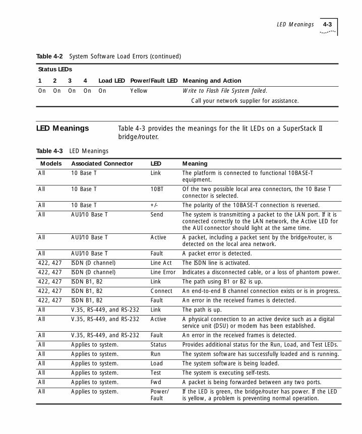
LED Meanings Table 4-3 provides the meanings for the lit LEDs on a SuperStack II bridge/router.
On On On On On Yellow Write to Flash File System failed.
Call your network supplier for assistance.
Table 4-2 System Software Load Errors (continued)
Status LEDs
1 2 3 4 Load LED Power/Fault LED Meaning and Action
Table 4-3 LED Meanings
Models Associated Connector LED Meaning
All 10 Base T Link The platform is connected to functional 10BASE-T equipment.
All 10 Base T 10BT Of the two possible local area connectors, the 10 Base T connector is selected.
All 10 Base T +/- The polarity of the 10BASE-T connection is reversed.
All AUI/10 Base T Send The system is transmitting a packet to the LAN port. If it is connected correctly to the LAN network, the Active LED for the AUI connector should light at the same time.
All AUI/10 Base T Active A packet, including a packet sent by the bridge/router, is detected on the local area network.
All AUI/10 Base T Fault A packet error is detected.
422, 427 ISDN (D channel) Line Act The ISDN line is activated.
422, 427 ISDN (D channel) Line Error Indicates a disconnected cable, or a loss of phantom power.
422, 427 ISDN B1, B2 Link The path using B1 or B2 is up.
422, 427 ISDN B1, B2 Connect An end-to-end B channel connection exists or is in progress.
422, 427 ISDN B1, B2 Fault An error in the received frames is detected.
All V.35, RS-449, and RS-232 Link The path is up.
All V.35, RS-449, and RS-232 Active A physical connection to an active device such as a digital service unit (DSU) or modem has been established.
All V.35, RS-449, and RS-232 Fault An error in the received frames is detected.
All Applies to system. Status Provides additional status for the Run, Load, and Test LEDs.
All Applies to system. Run The system software has successfully loaded and is running.
All Applies to system. Load The system software is being loaded.
All Applies to system. Test The system is executing self-tests.
All Applies to system. Fwd A packet is being forwarded between any two ports.
All Applies to system. Power/ Fault
If the LED is green, the bridge/router has power. If the LED is yellow, a problem is preventing normal operation.

4-4 CHAPTER 4: TROUBLESHOOTING
SS2EthHWBook Page 4 Wednesday, April 30, 1997 5:26 PM

SS2EthHWBook Page 1 Wednesday, April 30, 1997 5:26 PM
A
PROVISIONING YOUR ISDN LINEThis appendix provides North American (U.S. and Canada) and German provisioning information for the SuperStack II NETBuilder bridge/routers and boundary routers using an Integrated Services Digital Network (ISDN) line with a basic rate interface (BRI).
If your ISDN line is not provisioned correctly, you will not be able to use your SuperStack II bridge/router or boundary router to access a remote network.
Ordering North American ISDN BRI Services
To order ISDN service from your telephone company, follow these steps:
1 Call the telephone company and ask for the ISDN representative.
2 Tell the representative you want ISDN service for a SuperStack II NETBuilder ISDN bridge/router, and that you have the following information:
■ Line provisioning
■ ISDN outlet type
3 Give the representative the Bellcore ISDN ordering code (IOC). The IOC tells the telephone company which parameter settings to use for SuperStack II bridge/routers. The IOC for this product is “Capability R.”
Not all Regional Bell Operating Companies use IOCs. If the representative has the IOC for SuperStack II bridge/router listed, go to step 7; otherwise, continue on to step 4.
4 Ask the representative which ISDN switch type your line uses. Place a check mark in the appropriate box on the ISDN Information Sheet on on step 7.
5 Ask for an RJ-45 connector to be installed with your new ISDN outlet.

A-2 APPENDIX A: PROVISIONING YOUR ISDN LINE
SS2EthHWBook Page 2 Wednesday, April 30, 1997 5:26 PM
6 If desired, ask for an NT1 to connect your SuperStack II bridge/router to the ISDN line. (You can also purchase an NT1 from a reseller.)
7 Fill out the ISDN Information Sheet:
Ask for the following information:
■ ISDN Switch Type. Ask the representative which ISDN switch type your line uses. Place a check mark next to that switch on the ISDN Information Sheet. Each switch type has a corresponding provisioning information table later in this section.
■ Number of ISDN Phone Numbers. Your ISDN line can support one or two phone numbers. Specify how many phone numbers you are ordering.
■ Phone Numbers. Ask the telephone representative for your ISDN phone numbers and write them in the space provided.
■ Service Profile ID (SPID) Number. Ask the telephone representative for your SPID numbers. (For a multipoint line, the telephone representative should provide two SPID numbers.) A SPID number has 10–15 characters; for example, 0155512120. Your switch type may not require the SPID number.
ISDN Information Sheet
3Com SuperStack II Bridge/Router
ISDN Switch Type
AT&T 5ESS NI1 ❒
AT&T 5ESS Custom ❒
Northern Telecom DMS 100 ❒
Siemens EWSD ❒
Number of ISDN phone numbers (1 or 2)_________________________
Phone number 1 _____________________________________________
Phone number 2 _____________________________________________
SPID number for phone number 1 ______________________________
SPID number for phone number 2 ______________________________

North American Switch Provisioning Tables A-3
SS2EthHWBook Page 3 Wednesday, April 30, 1997 5:26 PM
Your telephone company gives you the phone number and SPID number after it installs your line.
If your telephone company has the IOC for a SuperStack II bridge/router or boundary router, you do not need to complete step 8.
8 Provide provisioning information that corresponds to your ISDN switch using the tables in the following sections.
This completes the ISDN ordering process for SuperStack II ISDN bridge/routers. Keep this information sheet handy; you will need it when you install your bridge/router.
North American Switch Provisioning Tables
This section provides provisioning information for the following switch types:
■ AT&T 5ESS
■ AT&T 5ESS Custom
■ DMS 100 and National ISDN
■ Siemens EWSD

A-4 APPENDIX A: PROVISIONING YOUR ISDN LINE
SS2EthHWBook Page 4 Wednesday, April 30, 1997 5:26 PM
AT&T 5ESS Switch To order ISDN service for an AT&T 5ESS switch, provide the telephone company with the information in Table A-1.
Table A-1 Ordering ISDN Service for an AT&T 5ESS Switch
Required Information Specification
Line type National ISDN 1 line
Line code 2B1Q (2B+D)
Interface type S/T interface with NT1 and RJ-45 jack
Maximum terminals (MAXTERM) 1
Maximum B channels (MAXB CHNL) 2
Actual user Yes
Circuit-switched data 2
Circuit-switched data channel Any
Terminal type A-Basic or E-Type (data only) Terminal
Display No
Circuit-switched data limit 2
Voice or data Data
Call appearance Idle
DN (directory number) must be set as follows:
Parameter Setting
B1 Circuit-switched data
B2 Circuit-switched data
D Signaling only
MAXTERM 1
MAXB CHNL 2
ACT USR Y
CSD 2
CSD CHL Any
TERMTYP TYPEA or TYPEE
Display No
CSD Limit 2
CA PREF 1

North American Switch Provisioning Tables A-5
SS2EthHWBook Page 5 Wednesday, April 30, 1997 5:26 PM
AT&T 5ESS CustomSwitch
To order ISDN service for an AT&T 5ESS custom switch, provide the telephone company with the information in Table A-2.
A point-to-point configuration on a SuperStack II bridge/router or boundary router is selected by setting the SPIDn1 and SPIDn2 parameters to none.
Table A-2 Ordering ISDN Service for an AT&T 5ESS Custom Switch
Required Information Specification
Line type ISDN line with point-to-point configuration
Line code 2B1Q (2B+D)
Interface type S/T interface with NT1 and RJ-45 jack
Maximum terminals (MAXTERM) 1
Maximum B channels (MAXB CHNL) 2
Circuit-switched data (CSD) 2
Circuit-switched data channel (CSD CHL)
Any
Terminal type (TERMTYP) A-Basic or E-Type (data only) Terminal
Display No
Voice or data Data
Call appearance preference Idle
DN must be set as follows:
Parameter Setting
B1 Circuit-switched data
B2 Circuit-switched data
D Signaling only
ACT USR Yes
TERMTYP TYPEA or TYPEE
CSD Limit 2
CA PREF 1

A-6 APPENDIX A: PROVISIONING YOUR ISDN LINE
SS2EthHWBook Page 6 Wednesday, April 30, 1997 5:26 PM
DMS 100 andNational ISDN
To order ISDN service for a DMS 100 or National ISDN switch, provide the telephone company with the information in Table A-3.
Table A-3 Ordering ISDN Service for a DMS 100 Switch
Required Information Specification
Line type DMS 100 or National ISDN 1line (in North America)
Line code 2B1Q (2B+D)
Interface type S/T interface with NT1 and RJ-45 jack
Circuit-switched option Yes
Bearer Restriction option No packet mode data (NOPMD)
Protocol Functional version 0 (PVC 0) for DMS 100
Functional version 2 (PVC 2) for National ISDN
SPID suffix 1 in North America only
Terminal endpoint identifier (TEI) Dynamic
Ring No
Key system (EKTS) No
Voice or data Data
DN must be set as follows:
Parameter Setting
B1 Circuit-switched data
B2 Circuit-switched data
D Signaling only
MAXTERM 1
MAXB CHNL 2
ACT USR Y
CSD 2
CSD CHL Any
Display No
CSD Limit 2
CA PREF 1

SPIDs A-7
SS2EthHWBook Page 7 Wednesday, April 30, 1997 5:26 PM
Siemens EWSDSwitch
To order ISDN service for a Siemens EWSD switch, provide the phone company with the information in Table A-3.
SPIDs When you request services, you may also need the following information about SPIDs and other service attributes:
■ Request multipoint, initializing terminal service; the maximum number of terminals is two. The service provider supplies you with two SPIDs.
■ If you request ISDN service from an AT&T 5ESS service provider and the switch is running custom (or non-national ISDN 1) software, the format is:
01 + 7-digit telephone number + 1-digit suffix.
■ If you request a different telephone number for each B channel, the suffix can be the same. A suffix of 0 is typical in this case. If you decide to use the same telephone number for both B channels, use a different suffix so that the two SPIDs are unique.
■ If you request NI-1 (national ISDN 1) service from an AT&T 5ESS service provider, the format is:
01 + 7-digit telephone number + 1-digit suffix + 2-digit TID (terminal identifier).
Table A-4 Ordering ISDN Service for a Siemens EWSD Switch
Required Information Specification
Line Type National ISDN 1 line
Line Code 2B+D
Interface Type S/T interface with NT1 and RJ-45 jack
Circuit-switched Option Yes
Bearer Restriction Option No packet mode data (NOPMD)
Protocol PPP
SPID suffix 1
Terminal Endpoint Identifier (TEI) Dynamic
Ring No
Maximum Keys 64
Key System (EKTS) No
Voice or Data Data
Lower Layer Compatibility Option for Data B channels

A-8 APPENDIX A: PROVISIONING YOUR ISDN LINE
SS2EthHWBook Page 8 Wednesday, April 30, 1997 5:26 PM
■ The SPID numbers must be unique. The 2-digit TID can be any number from 0 to 62. The TID has no effect on the operation of the SuperStack II bridge/router, but it is a necessary part of the SPID that the bridge/router uses to gain access to the ISDN network.
■ If you request ISDN service from a Northern Telecom DMS-100 service provider, the format is:
Area code + 7-digit telephone number + 0 to 8 digit suffix + 2 digit TID.
■ The TID can be any number from 0 to 62, but needs to be unique so that the SPIDs are also unique. This format applies when the switch is running Custom and NI-1 (North American 3) versions of software.
■ If you order AT&T 5ESS ISDN services, choose either a Type A or Type E terminal. The Type E terminal is preferable because it is for data only.
■ Do not request supplementary services, such as autohold or conference, because a SuperStack II bridge/router does not support them.
NT1s and Power Supplies
North American telephone companies require an NT1 and a power supply for every ISDN line. Your service provider or telephone company can provide you with an NT1 and power supply for a small monthly fee. However, you may prefer to purchase it from an ISDN equipment vendor. The NT1 and power supply may come in a single, standalone box or the two may be in separate units. In this discussion, the two units together are referred to as an NT1.
Telephone companies in North America use two kinds of NT1s, differentiated by the data encoding scheme used in transmitting data between the NT1 and the telephone company’s equipment. The two data encoding schemes are 2B1Q (two bits mapped into one quaternary symbol) and alternate mark inversion (AMI). The 2B1Q scheme is the dominant method in use today. The AMI scheme is older and rarely used.
Two power sources are available from an NT1 for CPE equipment. An ISDN telephone uses one power source. The SuperStack II bridge/router does not use either source. Instead, it detects the presence or absence of phantom power and can determine whether or not a telephone cord is plugged in.

Ordering German ISDN BRI Services A-9
SS2EthHWBook Page 9 Wednesday, April 30, 1997 5:26 PM
Not all NT1s provide phantom power; for example, the AMI NT1 from AT&T does not. If you connect the SuperStack II bridge/router to an NT1 that does not provide phantom power, you must turn off phantom power detection before you can dial successfully. Turn off phantom power detection by setting -PATH PhantomPower to Disable. For more information on this parameter, refer to the software reference guide.
Ordering German ISDN BRI Services
To order German ISDN services for a SuperStack II bridge/router, follow these steps:
1 Acquire a form entitled “Telefondienstauftrag im ISDN (Euro-ISDN-Anschluß)” from the Telekom.
2 At the top of the form, select “Neuanschluß.”
3 Under “Auftraggeber,” provide the requested information.
4 Under “Anschluß,” specify “Basisanschluß als Standardanschluß.”
By specifying “Basisanschluß als Standardanschluß, “ you are requesting standard basic rate interface (BRI) service. Under “Anschrift Standort,” provide the requested information.
5 Under “Anschlußnutzung,” specify “Mehrgeräteanschluß.”
By specifying “Mehrgeräteanschluß,” you are requesting a connection for multiple types of equipment, such as bridge/routers, telephones, faxes, and computers.
6 Sign your name at the bottom of the form.
The SuperStack II bridge/router software does not currently support the 1TR6 switch type. If you have an existing 1TR6 connection, request that the connection be changed to a Euro-ISDN connection using this form. In case the Telekom requests this information, the approval number for Germany (Bundesamt Für Zulassungen In Der Telekommunikation) is A115352E.
When ordering ISDN lines in Germany, make sure to order point-to-multipoint ISDN lines. The SuperStack II bridge/router does not support point-to-point configurations when attached to the German ISDN network.

A-10 APPENDIX A: PROVISIONING YOUR ISDN LINE
SS2EthHWBook Page 10 Wednesday, April 30, 1997 5:26 PM

SS2EthHWBook Page 1 Wednesday, April 30, 1997 5:26 PM
B
TECHNICAL SUPPORT3Com provides easy access to technical support information through a variety of services. This appendix describes these services.
Information contained in this appendix is correct at time of publication. For the very latest, we recommend that you access 3Com Corporation’s World Wide Web site as described below.
Online Technical Services
3Com offers worldwide product support 24 hours a day, 7 days a week, through the following online systems:
■ World Wide Web site
■ 3Com Bulletin Board Service (3ComBBS)
■ 3ComFactsSM automated fax service
■ 3ComForum on CompuServe® online service
World Wide Web Site Access the latest networking information on 3Com Corporation’s World Wide Web site by entering our URL into your Internet browser:
http://www.3Com.com/
This service features the latest information about 3Com solutions and technologies, customer service and support, news about the company, NetAge® Magazine, and more.
3Com Bulletin BoardService
3ComBBS contains patches, software, and drivers for all 3Com products, as well as technical articles. This service is available through analog modem or digital modem (ISDN) 24 hours a day, 7 days a week.

B-2 APPENDIX B: TECHNICAL SUPPORT
SS2EthHWBook Page 2 Wednesday, April 30, 1997 5:26 PM
Access by Analog Modem
To reach the service by modem, set your modem to 8 data bits, no parity, and 1 stop bit. Call the telephone number nearest you:
Access by Digital Modem
ISDN users can dial in to 3ComBBS using a digital modem for fast access up to 56 Kbps. To access 3ComBBS using ISDN, use the following number:
408 654 2703
3ComFactsAutomated Fax
Service
3Com Corporation’s interactive fax service, 3ComFacts, provides data sheets, technical articles, diagrams, and troubleshooting instructions on 3Com products 24 hours a day, 7 days a week.
Call 3ComFacts using your Touch-Tone telephone using one of these international access numbers:
Country Data Rate Telephone Number
Australia up to 14400 bps 61 2 9955 2073
Brazil up to 14400 bps 55 11 547 9666
France up to 14400 bps 33 1 6986 6954
Germany up to 28800 bps 4989 62732 188
Hong Kong up to 14400 bps 852 2537 5608
Italy (fee required) up to 14400 bps 39 2 27300680
Japan up to 14400 bps 81 3 3345 7266
Mexico up to 28800 bps 52 5 520 7853
P. R. of China up to 14400 bps 86 10 684 92351
Singapore up to 14400 bps 65 534 5693
Taiwan up to 14400 bps 886 2 377 5840
U.K. up to 28800 bps 44 1442 438278
U.S.A. up to 28800 bps 1 408 980 8204
Country Telephone Number
Hong Kong 852 2537 5610
U.K. 44 1442 438279
U.S.A. 1 408 727 7021

Support from Your Network Supplier B-3
SS2EthHWBook Page 3 Wednesday, April 30, 1997 5:26 PM
Local access numbers are available within the following countries:
3ComForum onCompuServe Online
Service
3ComForum is a CompuServe-based service containing patches, software, drivers, and technical articles about all 3Com products, as well as a messaging section for peer support. To use 3ComForum, you need a CompuServe account.
To use 3ComForum:
1 Log on to CompuServe.
2 Type go threecom
3 Press [Return] to see the 3ComForum main menu.
Support from Your Network Supplier
If additional assistance is required, contact your network supplier. Many suppliers are authorized 3Com service partners who are qualified to provide a variety of services, including network planning, installation, hardware maintenance, application training, and support services.
When you contact your network supplier for assistance, have the following information ready:
■ Diagnostic error messages
■ A list of system hardware and software, including revision levels
■ Details about recent configuration changes, if applicable
If you are unable to contact your network supplier, see the following section on how to contact 3Com.
CountryTelephone Number Country
Telephone Number
Australia 1800 678 515 Netherlands 06 0228049
Belgium 0800 71279 New Zealand 0800 446 398
Denmark 800 17319 Norway 800 11062
Finland 98 001 4444 Portugal 0505 442 607
France 05 90 81 58 Russia (Moscow only) 956 0815
Germany 0130 81 80 63 Singapore 800 6161 463
Hong Kong 800 933 486 Spain 900 964 445
Italy 1678 99085 Sweden 020 792954
Malaysia 1800 801 777 U.K. 0800 626403

B-4 APPENDIX B: TECHNICAL SUPPORT
SS2EthHWBook Page 4 Wednesday, April 30, 1997 5:26 PM
Support from 3Com If you are unable to receive support from your network supplier, technical support contracts are available from 3Com.
Contact your local 3Com sales office to find your authorized service provider using one of these numbers:
Regional Sales Office Telephone Number
3Com CorporationP.O. Box 581455400 Bayfront PlazaSanta Clara, California95052-8145U.S.A.
800 NET 3Com or 1 408 764 5000408 764 5001 (fax)
3Com Asia LimitedAustralia
China
Hong KongIndiaIndonesiaJapan
KoreaMalaysiaNew ZealandPhillippinesSingaporeTaiwanThailand
61 2 9937 5000 (Sydney)61 3 9866 8022 (Melbourne)8610 68492568 (Beijing)86 21 63740220 Ext 6115 (Shanghai)852 2501 111191 11 644 39746221 572 208881 6 536 3303 (Osaka)81 3 3345 7251 (Tokyo)822 2 319 471160 3 732 791064 9 366 9138632 892 447665 538 9368886 2 377 5850662 231 8151 4
3Com Benelux B.V.BelgiumNetherlands
32 2 725 020231 30 6029700
3Com CanadaCalgaryMontrealOttawaTorontoVancouver
403 265 3266514 683 3266613 566 7055416 498 3266604 434 3266
3Com European HQ 49 89 627320
3Com France 33 1 69 86 68 00
3Com GmbHAustriaCzech Republic/Slovak RepublicGermany (Central European HQ)HungaryPolandSwitzerland
43 1 513 4323420 2 21845 800
49 30 34 98790 (Berlin)49 89 627320 (Munich)36 1 250 83 4148 22 645135141 31 996 14 14
3Com Ireland 353 1 820 7077
3Com Latin AmericaU.S. HeadquartersNorthern Latin AmericaArgentinaBrazilChileColombiaMexicoPeruVenezuela
408 326 2093305 261 3266 (Miami, Florida)541 312 326655 11 546 0869562 633 9242571 629 411052 5 520 7841/784751 1 221 539958 2 953 8122
3Com MediterraneoItaly
Spain
39 2 253011 (Milan)39 6 5279941 (Rome)34 1 383 17 00
3Com Middle East 971 4 349049
3Com Nordic ABDenmarkFinlandNorwaySweden
45 39 27 85 00358 0 435 420 6747 22 18 40 0346 8 632 56 00
3Com Russia 007 095 258 09 40
3Com Southern Africa 27 11 807 4397
3Com UK Ltd. 44 131 220 8228 (Edinburgh)44 161 873 7717 (Manchester)44 162 889 7000 (Marlow)
Regional Sales Office Telephone Number

Returning Products for Repair B-5
SS2EthHWBook Page 5 Wednesday, April 30, 1997 5:26 PM
Returning Products for Repair
Before you send a product directly to 3Com for repair, you must first obtain a Return Materials Authorization (RMA) number. Products sent to 3Com without RMA numbers will be returned to the sender unopened, at the sender’s expense.
To obtain an RMA number, call or fax:
04/22/97
Country Telephone Number Fax Number
U.S.A. and Canada 1 800 876 3266, option 2 408 764 7120
Latin America 1 408 326 2927 408 764 7120
Europe, South Africa, and Middle East
44 1442 438125 44 1442 435822
Outside Europe, U.S.A., and Canada
1 408 326 2926 1 408 764 7120

SS2EthHWBook Page 6 Wednesday, April 30, 1997 5:26 PM

SS2EthHWBook Page 1 Wednesday, April 30, 1997 5:26 PM
INDEX
Numerics10BASE-T
cable 2-8connector 2-8
3Com Bulletin Board Service (3ComBBS) B-13Com sales offices B-43Com URL B-13ComFacts B-23ComForum B-3
AAT&T 5ESS switch
custom, ordering A-5standard, ordering A-4
AUIcable 2-7connector 2-7
auxiliary power 2-8
Bback panel 2-4bulletin board service B-1
Ccables
10BASE-T 2-8AUI 2-7console 2-4Ethernet 2-7, 2-8ISDN 2-17modem 2-7PC 2-5RS-232 straight-through 2-12RS-449 straight-through 2-11RS-449 to RS-530 2-13serial 2-10terminal 2-6V.35 adapter 2-14V.35 straight-through 2-10V.36 adapter 2-15X.21 adapter 2-16
cabling 1-4Ethernet 1-4ISDN 1-5serial connectors 1-6
cabling standards, Ethernet 2-9chassis panels 2-3CompuServe B-3connecting a console 1-8connectors
10 Base T 2-8AUI 2-7
conventionsnotice icons, About This Guide 1
coverreinstalling 3-4removing 3-1
Ddeleted image files 4-2DMS 100 switch, ordering A-6DRAM 2-1
installing 3-4
Eequipment required 1-1Ethernet
cables 2-7, 2-8cabling standards 2-9
Ffax service. See 3ComFactsfeet, attaching 1-2flash memory 2-1
installing 3-2front panel 2-3
GGerman ISDN BRI services A-9

2 INDEX
SS2EthHWBook Page 2 Wednesday, April 30, 1997 5:26 PM
Hhardware interrupt switch 2-4
Iinstalling
in a rack 1-3on a tabletop 1-2stacking with brackets 1-3
ISDNacquiring telecommunication services A-9cable 2-17German BRI services A-9information sheet A-2North American BRI services A-1phantom power A-9provisioning tables A-3SPIDs A-7
LLEDs
meanings 4-3normal 4-1
loading software, troubleshooting 4-2
Mmemory upgrading 3-1model features 2-1modem eliminator 1-4monitor utility 2-4mounting
in a rack 1-3on a tabletop 1-2stacking units 1-3
Nnetwork supplier support B-3NT1 1-5, A-8
Oonline technical services B-1
PPhantomPower parameter A-9physical specifications 2-18power supply redundancy 1-7power, turning off 1-9
Rrack-mount installation 1-3rack-mount kit 1-2Redundant Power System (RPS)
attaching 1-7cable 1-7
required equipment 1-1returning products for repair B-5RS-232 cable 2-12RS-449 cable
RS-530 conversion 2-13straight-through 2-11
Sserial
active ports 2-1cables 2-10
shipping carton contents 1-1shutting down 1-9Siemens EWSD switch, ordering A-7software recovery 1-1SPIDs A-7stacking units with mounting brackets 1-3switches
AT&T 5ESS A-4AT&T 5ESS (custom) A-5DMS 100 A-6National A-6Siemens EWSD A-7
Ttabletop installation 1-2technical support
3Com URL B-1bulletin board service B-1fax service B-2network suppliers B-3product repair B-5using CompuServe B-3
terminalconfiguration settings 1-8
troubleshootingdeleted image files 4-2during test phase 4-2LED meanings 4-3load errors 4-2load phase 4-2
UURL B-1

INDEX 3
SS2EthHWBook Page 3 Wednesday, April 30, 1997 5:26 PM
VV.35 cable
adapter 2-14straight-through 2-10
V.36 adapter cable 2-15
WWorld Wide Web (WWW) B-1
XX.21 adapter cable 2-16

4 INDEX
SS2EthHWBook Page 4 Wednesday, April 30, 1997 5:26 PM

SS2EthHWBook Page 5 Wednesday, April 30, 1997 5:26 PM
3Com Corporation LIFETIME LIMITED WARRANTY
INSTRUCTIONS FOR EDITING THIS WARRANTY (THIS CONDITONAL TEXT SHOULD BE TURNED OFF BY HIDING THE CONDITIONAL TAG “INSTRUCTIONS”:
YOU CAN MAKE THIS WARRANTY LIFETIME BY SHOWING THE CONDITIONAL TAG “LIFETIME”. USE THE SECTION BELOW ONLY IF WARRANTY IS DIFFERENT FROM THE STANDARD. REMEMBER TO INCLUDE ANY SPECIAL TERMS AND THEN SUBMIT IT TO LEGAL FOR REVIEW. IF YOU DO NOT REQUIRE THIS SECTION, HIDE THE CONDITIONAL TAG “SPECIAL WARRANTY”.
The duration of the warranty for the [name of product, 3C, ] is n years.
HARDWARE 3Com warrants its hardware products to be free from defects in workmanship and materials, under normal use and service, for the following lengths of time from the date of purchase from 3Com or its Authorized Reseller:
If a product does not operate as warranted above during the applicable warranty period, 3Com shall, at its option and expense, repair the defective product or part, deliver to Customer an equivalent product or part to replace the defective item, or refund to Customer the purchase price paid for the defective product. All products that are replaced will become the property of 3Com. Replacement products may be new or reconditioned. Any replaced or repaired product or part has a ninety (90) day warranty or the remainder of the initial warranty period, whichever is longer.
3Com shall not be responsible for any software, firmware, information, or memory data of Customer contained in, stored on, or integrated with any products returned to 3Com for repair, whether under warranty or not.
SOFTWARE 3Com warrants that the software programs licensed from it will perform in substantial conformance to the program specifications therefor for a period of ninety (90) days from the date of purchase from 3Com or its Authorized Reseller. 3Com warrants the media containing software against failure during the warranty period. No updates are provided. 3Com’s sole obligation with respect to this express warranty shall be (at 3Com’s discretion) to refund the purchase price paid by Customer for any defective software products, or to replace any defective media with software which substantially conforms to 3Com’s applicable published specifications. Customer assumes responsibility for the selection of the appropriate applications program and associated reference materials. 3Com makes no warranty or representation that its software products will work in combination with any hardware or applications software products provided by third-parties, that the operation of the software products will be uninterrupted or error free, or that all defects in the software products will be corrected. For any third-party products listed in the 3Com software product documentation or specifications as being compatible, 3Com will make reasonable efforts to provide compatibility, except where the noncompatibility is caused by a “bug” or defect in the third-party’s product.
STANDARD WARRANTY SERVICE
Standard warranty service for hardware products may be obtained by delivering the defective product, accompanied by a copy of the dated proof of purchase, to 3Com’s Corporate Service Center or to an Authorized 3Com Service Center during the applicable warranty period. Standard warranty service for software products may be obtained by telephoning 3Com’s Corporate Service Center or an Authorized 3Com Service Center, within the warranty period. Products returned to 3Com’s Corporate Service Center must be pre-authorized by 3Com with a Return Material Authorization (RMA) number marked on the outside of the package, and sent prepaid, insured, and packaged appropriately for safe shipment. The repaired or replaced item will be shipped to Customer, at 3Com’s expense, not later than thirty (30) days after receipt of the defective product by 3Com.
WARRANTIES EXCLUSIVE IF A 3COM PRODUCT DOES NOT OPERATE AS WARRANTED ABOVE, CUSTOMER’S SOLE REMEDY FOR BREACH OF THAT WARRANTY SHALL BE REPAIR, REPLACEMENT, OR REFUND OF THE PURCHASE PRICE PAID, AT 3COM’S OPTION. TO THE FULL EXTENT ALLOWED BY LAW, THE FOREGOING WARRANTIES AND REMEDIES ARE EXCLUSIVE AND ARE IN LIEU OF ALL OTHER WARRANTIES, TERMS, OR CONDITIONS, EXPRESS OR IMPLIED, EITHER IN FACT OR BY OPERATION OF LAW, STATUTORY OR OTHERWISE, INCLUDING WARRANTIES, TERMS, OR CONDITIONS OF MERCHANTABILITY, FITNESS FOR A PARTICULAR PURPOSE, AND SATISFACTORY QUALITY. 3COM NEITHER ASSUMES NOR AUTHORIZES ANY OTHER PERSON TO ASSUME FOR IT ANY OTHER LIABILITY IN CONNECTION WITH THE SALE, INSTALLATION, MAINTENANCE, OR USE OF ITS PRODUCTS.
Network adapters Lifetime
Other hardware products (unless otherwise specified above) 1 year
Spare parts and spares kits 90 days

SS2EthHWBook Page 6 Wednesday, April 30, 1997 5:26 PM
3COM SHALL NOT BE LIABLE UNDER THIS WARRANTY IF ITS TESTING AND EXAMINATION DISCLOSE THAT THE ALLEGED DEFECT IN THE PRODUCT DOES NOT EXIST OR WAS CAUSED BY CUSTOMER’S OR ANY THIRD PERSON’S MISUSE, NEGLECT, IMPROPER INSTALLATION OR TESTING, UNAUTHORIZED ATTEMPTS TO REPAIR OR MODIFY, OR ANY OTHER CAUSE BEYOND THE RANGE OF THE INTENDED USE, OR BY ACCIDENT, FIRE, LIGHTNING, OR OTHER HAZARD.
LIMITATION OF LIABILITY TO THE FULL EXTENT ALLOWED BY LAW, 3COM ALSO EXCLUDES FOR ITSELF AND ITS SUPPLIERS ANY LIABILITY, WHETHER BASED IN CONTRACT OR TORT (INCLUDING NEGLIGENCE), FOR INCIDENTAL, CONSEQUENTIAL, INDIRECT, SPECIAL, OR PUNITIVE DAMAGES OF ANY KIND, OR FOR LOSS OF REVENUE OR PROFITS, LOSS OF BUSINESS, LOSS OF INFORMATION OR DATA, OR OTHER FINANCIAL LOSS ARISING OUT OF OR IN CONNECTION WITH THE SALE, INSTALLATION, MAINTENANCE, USE, PERFORMANCE, FAILURE, OR INTERRUPTION OF ITS PRODUCTS, EVEN IF 3COM OR ITS AUTHORIZED RESELLER HAS BEEN ADVISED OF THE POSSIBILITY OF SUCH DAMAGES, AND LIMITS ITS LIABILITY TO REPAIR, REPLACEMENT, OR REFUND OF THE PURCHASE PRICE PAID, AT 3COM’S OPTION. THIS DISCLAIMER OF LIABILITY FOR DAMAGES WILL NOT BE AFFECTED IF ANY REMEDY PROVIDED HEREIN SHALL FAIL OF ITS ESSENTIAL PURPOSE.
Some countries, states, or provinces do not allow the exclusion or limitation of implied warranties or the limitation of incidental or consequential damages for certain products supplied to consumers or the limitation for personal injury, so the above limitations and exclusions may be limited in their application to you. This warranty gives you specific legal rights which may vary depending on local law.
GOVERNING LAW This Limited Warranty shall be governed by the laws of the state of California.
3Com Corporation, 5400 Bayfront Plaza, Santa Clara, CA 95052-8145 (408) 764-5000
9/1/96