instantaneous water heater hydraulic control, thermo...
TRANSCRIPT

VI.GE.Q1.02 Produced by Danfoss Redan A/S · 10.2010
Instantaneous water heater
Instructions
Table of contents
Hydraulic control, Thermo-hydraulic control
EASY START-UP..... ...............................................2
Types / Main components ..............................................3
General / Mounting & Start-up .....................................4
Akva Vita Type A .................................6
Akva Lux II Type B .................................7
Akva Vita II F Type C .................................8
Akva Lux II F Type D .................................9
DHW circulation - Types C + D ....................................10
Troubleshooting - Type A ............................................ 14
Troubleshooting - Types B, C, D ................................. 15
Maintenance .................................................................... 16
EU Declaration of conformity..................................... 19

2 VI.GE.Q1.02 Produced by Danfoss Redan A/S · 10.2010
Instructions Instantaneous water heater
1. The water heater is prepared for wall-mounting. The mounting sheet on the back of the water heater has got holes for screw installation. Fasten the water heater on the wall with two screws, bolts, expansion bolts or the like.
2. Prior to installation any unused connections and shut-off valves should be sealed with a plug.
3. IMPORTANT! Due to vibrations during trans-port all connections must be checked and tightened before the installation.
4. For systems with safety valve, connection for drain must be established in compliance with local regulations.
5. For installations with domestic hot wa-ter circulation remember to switch from bypass to DHW circulation control and to install circulation pump and non-return valve. Connect pump to power supply, but do not switch on the pump (see page 5 DHW circulation). Please see instructions for domestic hot water circulation control.
Mounting - start-up 6. Carefully open the ball valves on DH sup-ply. Subsequently open the remaining ball valves.
7. Check the water heater and the domestic installation carefully for any leakage.
8. Perform pressure testing of the domestic installation according to local regulations.
9. Switch on circulation pump, if any.
10. Finally adjust the water heater according to the enclosed installation instructions.
11. IMPORTANT! Heating and cooling of the sys-tem may cause leakages. Therefore tighten-ing of all connections may be necessary after commencement of operation.
Mounting holes
Supply ReturnDCW DHW
Circ.
DH
160
EASY START-UP !
Dimensioned sketch / ConnectionsType A (Please see page 3)Akva Vita
Type B (Please see page 3) Akva Lux II
Dimensioned sketches for type C - Akva Vita II F and type D - Akva Lux II F are not available. Connections, however, are as shown to the right.
Measurements:
H 550 x W 440 x D 150 mm
A A
B
B
Mounting and start-up.Please follow the below start-up instructions.
1. Domestic cold water (DCW)
2. Domestic hot water (DHW)
3. District heating (DH) supply
4. District heating (DH) return
5. Circulation
6. Blow-off pipe from safety valve
optional
70
5
632 1 4
8060 60
40
255
200
391
555
420
9025
430
200
305
1 23
4 5
463
6
Wall
Top view
6
43
5
21
175
200
60 80 60
40Mounting holes
305
3 VI.GE.Q1.02 Produced by Danfoss Redan A/S · 10.2010
Instructions Instantaneous water heater
1
2
3
4
4A
1
1
3
2
3
4a
2
5
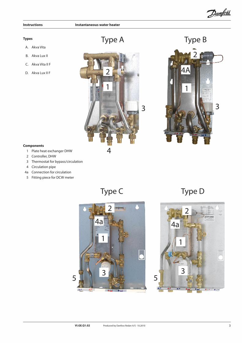
Types A. Akva Vita B. Akva Lux II C. Akva Vita II F D. Akva Lux II F
Components
1 Plate heat exchanger DHW
2 Controller, DHW
3 Thermostat for bypass/circulation
4 Circulation pipe
4a Connection for circulation
5 Fitting piece for DCW meter
Type A Type B
Type D
1
2
3
4a
5
Type C

4 VI.GE.Q1.02 Produced by Danfoss Redan A/S · 10.2010
Instructions Instantaneous water heater
Safety notes To avoid injury of persons and damages to the device, it is absolutely necessary to read and observe these instructions carefully.
Necessary assembly, start-up and maintenance work must be performed by qualified and authorized personnel only.
Please comply with the instructions of the system manufacturer or system operator.
Unused connections and shut-off valves must be sealed with a plug. The plugs must be removed by an authorized service technician only.
Choice of materialsChoice of materials always in compliance with local legislation
Warning of high pressure and temperatureThe maximum temperature of the flow medium in the Akva Lux II is 110 °C.
The maximum operating pressure of the water heater is 16 bar.
Be aware of the installation’s permissible system pressure and temperature.
The risk of persons being injured and equipment damaged increases considerably if the recom-mended permissible operating parameters are exceeded.
We recommend that the water heater is equipped with safety valve, however, always in compliance with local regulations.
Warning of hot surfaceThe water heater has got hot surfaces, which can cause skin burns. Please be extremely cautious in close proximity to the water heater.
Warning of transport damageBefore water heater installation, please make sure that the water heater has not been damaged during transport.
Sound level≤ 55 dB
Corrosion protectionAll pipes and components are made of stainless steel and brass.
The maximum chloride compounds of the flow medium should not be higher than 300 mg/l.
The risk of equipment corrosion increases consi-derably if the recommended permissible chloride compounds are exceeded
Storage If the water heater is stored before installation, make sure that the place is dry and heated.
Disposal
This product consists of materials which must not be disposed of together with domestic waste. Dismantle the product and sort the components in various groups before disposal. Observe the disposal rules of the local legislation.

5 VI.GE.Q1.02 Produced by Danfoss Redan A/S · 10.2010
Instructions Instantaneous water heater
DHW circulationFor house installations with DHW circulation a control change from bypass to circulation must be performed. Type A is supplied with circulation pipe.For DHW circulation control for types B, C and D a circulation set is available as optional equipment and must be fittet on site.
Remember circulation pump and non-return valve assembly. The pump must pump water in direction towards the water heater.
Control change from bypass to DHW circulation - please see separate instructions for the various types.
Mounting The water heater must be installed and connected by authorized service personnel only.
Installation must be in compliance with the local standards and regulations.
Allow for adequate space around the water heater for mounting and maintenance purposes.
Prior to the water heater installation all water heater pipes and connections should be cleaned and rinsed.
The water heater should be wall-mounted. The mounting sheet on the back of the water heater has got holes for screw installation.
A symbol for each of the different connections is placed on the water heater.
Tightening of connectionsDue to vibrations during transport all connections must be checked and tightened before the water heater is installed. After having added water to the system and after having observed that the water heaters operates in accordance with the
dimensioning basis, the connections must be tightened again and the water heater can be taken into continuous use.
DCW meter assembly, fitting piece The flat station is equipped with a fitting piece for insertion of a DCW meter.
Assembly of DCW meter Loosen nuts from fitting piece, remove fitting piece and replace with DCW meter. After mounting of DCW meter remember to check all threaded connections and tighten if necessary.
Filling, start-up Prior to the water heater installation all its pipes and connections should be cleaned and rinsed. After that the strainers should be cleaned.
Before starting-up, check if:- pipes are connected according to the circuit
diagram,- release valves are shut off,- threaded and flanged connections are
tightened.
Fill the heat exchanger / the system with water:
1) Carefully open ball valves on DH supply, 2) Finally open the other ball valves.(Please note that the ball valves are not part of the delivery).
After having added water to the system, that the shut-off valves should be opened and the operation of the substation must be ob-served (e.g. temperatures, pressure, thermal expansion, leakages). Observe the operation of the substation. If the substation operates in ac-cordance with the designed parameters, it can be taken into continuous use.
All Danfoss plate heat exchangers and substa-tions have been leak tested prior to delivery.
Electrical connection 230 V AC
DHW circulation

6 VI.GE.Q1.02 Produced by Danfoss Redan A/S · 10.2010
Instructions Instantaneous water heater - type A
PLEASE NOTE that other variants may be supplied. The control function, however, is basically as de-scribed below.
DescriptionThe domestic hot water is prepared in the heat exchanger based on the flow principle and the temperature is controlled by the hydraulic self-acting PM controller (2).
DHW temperature control.The DHW temperature control is realized by turn-ing the lever towards the red (hot) or blue (cold) mark. The temperature should be set to 45-50 °C at normal use (7-8 l/min). The temperature should never exceed 55 °C to avoid lime scale precipita-tion in the heat exchanger.If it is not possible to set the temperature accord-ing to the above recommendations, it is recom-mended to change the standard controller set-ting. - See separate instruction “Troubleshooting”.
Bypass or circulation thermostat.Bypass (standard).As a standard the substation is equipped with a bypass thermostat, Danfoss FJVR (3) with return temperature limiter 10/50 C° , which ensures that hot water is available immediately, when tapping starts. It is recommended to set the thermostat in pos.3.If the water temperature rises too slowly it can be necessary to set the thermostat at higher value.
DHW circulation Switching to DHW circulation control is possible from a constructional point of view, requiring no extra components.
Circulation thermostatIf the substation is connected to the DHW circulation system in the building, the FJVR thermostat (3) will function as a circulation thermostat and control the circulation water temperature, independently of the set DHW temperature. It is recommended to set the thermostat in pos 3.
• Loosennutonupperpartofcirculationpipe and remove blind plate.• Remove4mmconicalscrewinpos.B.• Loosenandmovecapillarytubetogetherwith union nut from pos. A to B.• Screwthe4mmconicalscrewfrompos.B onto the muff in pos. A.• ConnectDHWcirculationsystemwithwater heater connection pipe.
General
Domestic hot water
DHW temperature control
Bypass thermostat
DHW-circulation
Circulation thermostat
Control change from bypass to circulation
IMPORTANT
Remember circulation pump and non-
return valve asssembly (this is not part of
the delivery and must be fitted remotely
on site). The pump must pump water in
direction towards the substation.
Connection of capillary tube for circulation
Blind plate(remove if circulation)
Handle for temperature setting
Approximate scale setting:Pos. 2 = 30°C 3 = 40°C 4 = 45°C
B
4
3
2
A

7 VI.GE.Q1.02 Produced by Danfoss Redan A/S · 10.2010
Instructions Instantaneous water heater - type B
PLEASE NOTE that other variants may be supplied. The control function, however, is basically as de-scribed below.
DescriptionThe domestic hot water is prepared in the heat ex-changer based on the flow principle and the tem-perature is controlled by the combined hydraulic and thermostatic self-acting controller PTC2+P with integrated differential pressure controller (2).
DHW temperature control. The DHW temperature setting is adjusted with the handle for temperature setting, by turning the handle in “+” direction (warmer), or “-” direc-tion (colder). The temperature should be set to 45-50 °C at normal use (7-8 l/min.) The tempera-ture should never exceed 55 °C to avoid lime scale precipitation in the heat exchanger.
Bypass or circulation thermostat.Bypass (standard).As a standard the substation is equipped with a bypass thermostat, Danfoss FJVR (3) with return temperature limiter 10/50 C° , which ensures that hot water is available immediately, when tapping starts. It is recommended to set the thermostat in pos.3.If the water temperature rises too slowly it can be necessary to set the thermostat at higher value.
DHW circulation Switching to DHW circulation control is possible from a constructional point of view, requiring only an additional circulation set. The components for DHW circulation are not part of the delivery and must be ordered separately and mounted on site.
Circulation thermostatIf the substation is connected to the DHW circulation system in the building, the FJVR thermostat (3) will function as a circulation thermostat and control the circulation water temperature, independently of the set DHW temperature. It is recommended to set the thermostat in pos 3. • Demountplugsinpos.C and B (6 mm Allen key).• Mount3/8”x3/4”hexagonnippleinpos.C (pack) and mount circulation pipe in hexagon nipple.
4 mm capillary tube (heat exchanger XB 06H-1 26):• Mount1/4”hexagonnippleinpos.B(pack).• Loosenandmovecapillarytubetogetherwith union nut from pos. D to B. • Screwthe4mmconicalscrewfromposBonto the muff in pos. A.
6 mm capillary tube (heat exchanger XB 06H-1 40):• Mount1/4”hexagonnippleinpos.B(pack).• Demountcapillarytubeandunionnutinpos.F and G (scrap).• Plugtheholeinpos.Fwithunionnut+ball.• Fitnewcapillarytubefrompos.Ftopos.Bby means of union nut and cutting ring.
General
Domestic hot water
DHW temperature control
Bypass thermostat
DHW circulation
Circulation thermostat
Control change from bypass to circulation
IMPORTANT
Remember circulation pump and non-
return valve asssembly (this is not part of
the delivery and must be fitted remotely
on site). The pump must pump water in
direction towards the substation.
Connection of circulation pipe
Connection of capillary tube for circulation
Approximate scale setting:Pos. 2 = 30°C 3 = 40°C 4 = 45°C
3
2
6 mm F G
Handle for temperature setting
E
BC
4 mm D

8 VI.GE.Q1.02 Produced by Danfoss Redan A/S · 10.2010
Instructions Instantaneous water heater - Type C
PLEASE NOTE that other variants may be supplied. The control function, however, is basically as de-scribed below.
DescriptionThe domestic hot water is prepared in the heat exchanger based on the flow principle and the temperature is controlled by the hydraulic self-acting controller PM2+P with integrated differen-tial pressure controller (2)
DHW temperature control The DHW temperature setting is adjusted with the handle in “red” direction (warmer), or in “blue” direction (colder). The temperature should be set to 45-50 °C at normal use (7-8 l/min.) The tem-perature should never exceed 55 °C to avoid lime scale precipitation in the heat exchanger.
Bypass or circulation thermostat.Bypass (standard).As a standard the substation is equipped with a bypass thermostat, Danfoss FJVR (3) with return temperature limiter 10/50 C° , which ensures that hot water is available immediately, when tapping starts. It is recommended to set the thermostat in pos.3.If the water temperature rises too slowly it can be necessary to set the thermostat at higher value.
DHW circulation Switching to DHW circulation control is possible from a constructional point of view, requiring only an additional circulation set. The components for DHW circulation are not part of the delivery and must be ordered separately and mounted on site.
Circulation thermostatIf the substation is connected to the DHW circulation system in the building, the FJVR thermostat (3) will function as a circulation thermostat and control the circulation water temperature, independently of the set DHW temperature. It is recommended to set the thermostat in pos 3.
For DHW circulation control of the instanta-neous water heater type C - Akva Vita II F - 3 circulation sets are available as optional equip-ment.
The 3 circulation sets and control change pos-sibilities from bypass to DHW circulation will be described on pages 10, 11 and 12.
Please note, that this description applies both to Akva Vita II F and Akva Lux II F.
General
Domestic hot water
DHW temperature control
Bypass thermostat
DHW-Zirkulation
Circulation thermostat
Control change from bypass to DHW circulation
Approximate scale settingPos 2 = 30°C 3 = 40°C 4 = 45°C
3
2
Handle for temperature setting

9 VI.GE.Q1.02 Produced by Danfoss Redan A/S · 10.2010
Instructions Instantaneous water heater - type D
PLEASE NOTE that other variants may be supplied. The control function, however, is basically as de-scribed below.
DescriptionThe domestic hot water is prepared in the heat ex-changer based on the flow principle and the tem-perature is controlled by the combined hydraulic and thermostatic self-acting controller PTC2+P with integrated differential pressure controller (2).
DHW temperature control The DHW temperature setting is adjusted with the handle for temperature setting, by turning the handle in “+” direction (warmer), or “-” direc-tion (colder). The temperature should be set to 45-50 °C at normal use (7-8 l/min.) The tempera-ture should never exceed 55 °C to avoid lime scale precipitation in the heat exchanger.
Bypass or circulation thermostatBypass (standard).As a standard the substation is equipped with a bypass thermostat, Danfoss FJVR (3) with return temperature limiter 10/50 C° , which ensures that hot water is available immediately, when tapping starts. It is recommended to set the thermostat in pos.3.If the water temperature rises too slowly it can be necessary to set the thermostat at higher value.
DHW circulation Switching to DHW circulation control is possible from a constructional point of view, requiring only an additional circulation set. The components for DHW circulation are not part of the delivery and must be ordered separately and mounted on site.
Circulation thermostatIf the substation is connected to the DHW circulation system in the building, the FJVR thermostat (3) will function as a circulation thermostat and control the circulation water temperature, independently of the set DHW temperature. It is recommended to set the thermostat in pos 3.
For DHW circulation control of the instantaneous water heater type D - Akva Lux II F - 3 circulation sets are available as optional equipment.
The 3 circulation sets and control change pos-sibilities from bypass to DHW circulation will be described on pages 10, 11 and 12.
Please note, that this description applies both to Akva Vita II F and Akva Lux II F.
General
Domestic hot water
DHW temperature control
Bypass thermostat
DHW circulation
Circulation thermostat
Control change from bypass to DHW circulation
Approximate scale settingPos. 2 = 30°C 3 = 40°C 4 = 45°C
3
2
Handle for temperature setting

10 VI.GE.Q1.02 Produced by Danfoss Redan A/S · 10.2010
Instructions Instantaneous water heater - type C and D
3 + 6
3 + 4
BConnection of capil-lary tube by means of union nut + cutting ring.
• Demountplugs in pos. C and B (6 mm Allen key).• Mount3/8”x3/4”hexagonnipple,3/4Ø21,4 mm union nut and ½” x 28,5 mm hexagon nipple in pos. C (pack) (for mounting of circula- tion pipe (not part of the delivery)).
• Mount1/4”x6mmhexagonnippleinpos.B (pack).
• Demountcapillarytubeandunionnutinpos. F and G (scrap).• Plugtheholeinpos.Fwithunionnut+ball plug
• Demount3/4”pluginpos.H
• DemountFJVRthermostatinposI.Unscrew 3/4” reducer bushing from FJVR thermostat and scrap.
• Mount3/4”plug+gasketinpos.I.
• MountFJVRthermostatinpos.H.
• Fitnewcapillarytubefrompos.Gtopos.Bby means of union nut and cutting ring.
I
Union nut + ball plug
Union nut + cutting ring
I
Control change from bypass to DHW circulation
Circulation set 1
1) 1 pc. 3/8” x 3/4” hexagon nipple2) 1 pc. 1/4”x 6 mm hexagon nipple3) 3 pc. union nut 6 mm 4) 1 pc. ball plug 5)1pc.capillarytubeØ6mm6) 2 pc. cutting ring7)1pc.3/4Ø21,4mmunionnut8) 1 pc. ½” x 28,5 mm hexagon nipple
(Please note that this circulation set is prepared for application in other substation types too. - Therefore excess components may occur and we ask you please to ignore these).
Remember circulation pump and non-
return valve assembly (this is not part of the
delivery and must be fitted remotely on site).
The pump must pump water in direction
towards the substation.H
G
2
3 + 6
Connection of circulation pipe
Connection of capillary tube for circulation
6 mm F
G
B
C1
7 + 8

11 VI.GE.Q1.02 Produced by Danfoss Redan A/S · 10.2010
Instructions Instantaneous water heater - type C and D
3 + 6
3 + 4
BConnection of capil-lary tube by means of union nut + cutting ring
• Demountplugs in pos. C and B (6 mm Allen key).• Mount3/8”x3/4”hexagonnippleinpos.C (pack) and mount circulation pipe (E) in hexa- gon nipple (pos. C). (Please note that the width of the station will increase by 120 mm).
• Mount1/4”x6mmhexagonnippleinpos.B (pack).
• Demountcapillarytubeandunionnutinpos. F and G (scrap).• Plugtheholeinpos.Fwithunionnut+ball plug.
• Demount3/4”pluginpos.H.
• DemountFJVRthermostatinpos.I.Unscrew 3/4” reducer bushing from FJVR thermostat and scrap.
• Mount3/4”plug+gasketinpos.I.
• MountFJVRthermostatinpos.H.
• Fitnewcapillarytubefrompos.Gtopos.Bby means of union nut and cutting ring.
I
Union nut + ball plug
Union nut + cutting ring
I
H
G
2
3 +6
Connection of circulation pipe
Connection of capillary tube for circulation
6 mm F
G
E
B
C
1Control change from bypass to DHW circulation
Circulation set 2
1) 1 pc. 3/8” x 3/4” hexagon nipple2) 1 pc. 1/4”x 6 mm hexagon nipple3) 3 pc. union nut 6 mm 4) 1 pc. ball plug 5)1pc.capillarytubeØ6mm6) 2 pc. cutting ring7) 1 pc. hexagon nipple ½” x ½”8) 1 pc.circulation pipe ø15 mm
(Please note that this circulation set is prepared for multiple applica-tions. - Therefore excess compo-nents may occur and we ask you please to disregard these).
Remember circulation pump and non-
return valve assembly (this is not part of the
delivery and must be fitted remotely on site).
The pump must pump water in direction
towards the substation.
7 + 8

12 VI.GE.Q1.02 Produced by Danfoss Redan A/S · 10.2010
Instructions Instantaneous water heater - type C and D
3 + 6
3 + 4
BConnection of capil-lary tube by means of union nut + cutting ring
• Demountplugs in pos. C and B (6 mm Allen key).• Mount3/8”x3/4”hexagonnippleinpos.C (pack) and mount circulation pipe (E) in hexa- gon nipple (pos. C). (Please note that the width of the station will increase by 120 mm).
• Mount1/4”x6mmhexagonnippleinpos.B (pack).
• Demountcapillarytubeandunionnutinpos. F and G (scrap).• Plugtheholeinpos.Fwithunionnut+ball plug.
• Demount3/4”pluginpos.H.
• DemountFJVRthermostatinpos.I.Unscrew 3/4” reducer bushing from FJVR thermostat and scrap.
• Mount3/4”plug+gasketinpos.I.
• MountFJVRthermostatinpos.H.
• Fitnewcapillarytubefrompos.Gtopos.Bby means of union nut and cutting ring.
I
Union nut + ball plug
Union nut + cutting ring
I
H
G
2
3 +6
Connection of circulation pipe
Connection of capillary tube for circulation
6 mm F
G
E
B
C
1Control change from bypass to DHW circulation
Circulation set 3
1) 1 pc. 3/8” x 3/4” hexagon nipple2) 1 pc. 1/4”x 6 mm hexagon nipple3) 3 pc. union nut 6 mm 4) 1 pc. ball plug 5)1pc.capillarytubeØ6mm6) 2 pc. cutting ring7) 1 pc. hexagon nipple ½” x ½”8) 1 pc.circulation pipe ø15 mm9) 1 pc. pump Wilo Star-Z 1510) 1 pc. non-return valve
(Please note that this circulation set is prepared for multiple applica-tions. - Therefore excess compo-nents may occur and we ask you please to disregard these)
Remember circulation pump and non-
return valve assembly (this is not part of the
delivery and must be fitted remotely on site).
The pump must pump water in direction
towards the substation.
7

13 VI.GE.Q1.02 Produced by Danfoss Redan A/S · 10.2010
Instructions Instantaneous water heater - type C and D
Circulation pump Pump start-up Do not start up the pump until the system has been filled with the flow media. The pump vents itself au-tomatically after a short operational period. Short-term dry-running will not harm the pump.
For more information about the pump, please refer to enclosed installation and maintenance instruc-tions.WILO-STAR-Z 15Installation and Maintenance Instructions

14 VI.GE.Q1.02 Produced by Danfoss Redan A/S · 10.2010
Instructions Instantaneous water heater
TroubleshootingDomestic hot water
PM controller
Instantaneous water heaterType A
Problem Possible cause Solution
In general: Does the controller work incorrectly
If the quantity of tapping water is normal (temperature unim-portant) it indicates that the PM controller works correctly.
Locate defect in another part of the installation (see below).
In general: Are the operating conditions satisfactory?
The water heater requires a DH supply temperature of mini-mum 60 °C and a differential pressure during operation according to the information stated in the product sheet for the water heaters.
Contact district heating sup-plier.
PM controller leaking; Water leaking from Allen screws at the central part of PM controller.
One of the two O-rings is defec-tive (does not influence the PM operation). If a non-return valve is installed in the DCW inlet (e.g. in the house service connection or in DCW meter) a safety valve should be mounted between the non-return valve and the DHW plate heat exchanger.
Replace PM controller (use new sealing).
DHW tap load too low.The diaphragm of the PM con-troller is defective.
Replace diaphragm or PM controller.
DHW tap load too low; Tap temperature too low; Tap temperature fluctuates.
- PM controller wrongly ad- justed;- Strainer in DH supply clogged.- Defective non-return valve in thermostatic battery (DHW tap temperature lower than DHW from water heater).- Defective non-return valve in DHW circulation (DHW circula- tion return pipe is getting cold during tapping of DHW).- Lime scale precipitation in the DHW plate heat exchanger (DH Δt too low during DHW tapping.- Dirt in PM controller.- DCW flow too high (big nom- nal diameter of pipe, high DCW pressure), in total max. 16-17 litres per minute.
Setting, see Control chapter.
Clean strainer.
Clean or replace non-return valve.
Clean or replace non-return valve.
Replace the plate heat ex-changer.
Cleaning, see PM controller instruction.
DCW reduction
DH return temperature too high while on standby; The plate heat exchanger is cold.
The by-pass thermostat is de-fective or wrongly adjusted.
Replace or adjust by-pass ther-mostat correctly.
DH return temperature too high while on standby; The plate heat exchanger is hot.
Dirt (sand, iron splinters or simi-lar) in PM controller. Controller does not close. Noise from flow can often be heard.
Move handle several times be-tween red and blue markings; at the same time do several hot-water tappings. Clean PM controller.
DH return temperature too high during hot water tapping.
Lime scale precipitation in the DHW plate heat exchanger.
Replace the plate heat ex-changer.
Connecting pieces of the PM controller do not fit the water heater.
In particular when replacing PM controller in old water heater.
Loosen Allen screws; turn half of the PM controller 180°.

15 VI.GE.Q1.02 Produced by Danfoss Redan A/S · 10.2010
Instructions Instantaneous water heater
TroubleshootingDomestic hot water
PM 2 + P controllerPTC2 + P controller
Instantaneous water heatersTypes B, C and D
Problem Possible cause Solution
In general: Does the controller work incorrectly
If the quantity of tap water is normal (temperature unimportant), it indicates that the controller works correctly.
Locate defect in another part of the installation (see below).
In general: Are the operating conditions satisfactory?
The substation requires a DH supply temperature of mini-mum 60 °C and a differential pressure during operation according to the information stated in the product sheet.
Contact district heating sup-plier.
DHW tap load too low; Tap temperature too low; Tap temperature fluctuates
- Strainer in DH supply clogged.- Defective non-return valve in
thermostatic battery (DHW tap temperature lower than DHW from unit).
- Defective non-return valve in hot water circulation (circula-tion return pipe is getting cold during tapping of hot water).
- Lime scale precipitation in plate heat exchanger for DHW (Δt primary too low during DHW tapping).
- DCW flow too high (big nomi-nal diameter of pipe, high DCW pressure), in total max. 16-17 litres per minute.
Clean strainer.
Clean or replace non-return valve.
Clean or replace non-return valve.
Replace the plate heat exchanger.
DCW reduction.
DH return water temperature too high while on standby; The plate heat exchanger is cold.
The bypass thermostat is defective or wrongly adjusted.
Replace or adjust bypass ther-mostat correctly.
DH return water temperature too high while on standby; The plate heat exchanger is hot.
Short-circuiting of plate heat exchanger or defective control-ler.
Replace plate heat exchanger or controller.
DH return temperature too high during hot water tapping.
Lime scale precipitation in the plate heat exchanger for DHW.
Replace the plate heat exchanger.

16 VI.GE.Q1.02 Produced by Danfoss Redan A/S · 10.2010
Instructions Instantaneous water heater
The substation requires little monitoring, apart from routine checks and cleaning of strainers. To ensure the best operating conditions regular in-spection of the substation and a check of all re-levant operating parameters are recommended, for example in connection with meter reading.
Meter readingWe recommend that you read your meter regu-larly and that you write down the meter readings.
Cooling / Return temperature readingThe cooling, i.e. the temperature difference be-tween district heating supply and district heat-ing return is of great importance for the total heat economy. It is therefore very important to observe the supply and return temperatures. Nor-mal temperature difference is 30-35 °C CleaningAll strainers should be checked and cleaned at least once every year, typically in connection with start-up of the heating system.
Tightening of connectionsAll threaded and flanged connections should be checked and tightened in connection with meter reading. All threaded and flanged connections should be tightened regularly and especially in connection with start-up after the summer pe-riod.
Safety valveThe safety valves’ task is to protect the substation from pressures exceeding the permissible pressure. The blow-off pipe of the safety valves must not be closed. The blow-off pipe outlet should be placed so that it provides safety relief and it is possible to observe water dropping from the safety valves. It is advisable to check the operation of the safety valves by turning the valve head in the indicated direction.
StrainerStrainers should frequently be cleaned from sediments by authorized personnel, according to producer’s instructions and dependent on the substation’s operating conditions.
Maintenance
Meter reading
Cooling
Cleaning
Tightening
Safety valve
Strainer

17 VI.GE.Q1.02 Produced by Danfoss Redan A/S · 10.2010
Instructions Instantaneous water heater
Notes:

18 VI.GE.Q1.02 Produced by Danfoss Redan A/S · 10.2010
Instructions Instantaneous water heater
Notes:

Danfoss Redan A/S District Energy
Omega 7, Søften DK-8382 Hinnerup
Telephone +45 87 43 89 43
EC-DECLARATION OF CONFORMITY
For CE marking in EU (European Union)
Danfoss Redan A/S District Energy DK-8382 Hinnerup
Declares under our sole responsibility that below products including all available power and control options:
Instantaneous Water Heaters Main components: See instruction
Covered by this declaration is in conformity with the following directive(s), standard(s) or other norma-tive document(s), provided that the products are used in accordance with our instructions. EU Directives:
EMC Directive 2004/108/EEC EN 61000-6-1 2007 Electromagnetic compatibility- Generic standard: Immunity for residential, commercial and light industry.
EN 61000-6-2 2007 Electromagnetic compatibility- Generic standard: Immunity industry. EN 61000-6-3 2007 Electromagnetic compatibility- Generic standard: Emission for residential, commercial and light industry. EN 61000-6-4 2007 Electromagnetic compatibility- Generic standard: Emission industry.
Machinery Directive 2006/42/EEC EN ISO 14121-1 Safety of machinery -- Risk assessment
EN 60204-1-Safety of machinery - Electrical equipment of machines — Part 1: General requirements
PED Directive 97/23/EEC Conformity assessment procedure followed: Module A - Internal control of production All substations that falls under Article 3 §3 and category 1 shall not be CE-marked according to this directive
CE marked affixed year 2010 Approved by: Place and date of issue: Hinnerup, Aug. 24th, 2010 Name: Thavarupan Perinpam Title: Quality and Lean Manager

20 VI.GE.R1.02 Produced by Danfoss Redan A/S · 10.2010
Instructions Instantaneous water heater
Danfoss Redan A/SOmega 7, Søften33-35DK-8382 HinnerupTelefon: +45 87438943Telefax: +45 [email protected]