institute of mechanics and advanced materials sensitivity analysis and shape optimisation with...
TRANSCRIPT

Institute of Mechanics and Advanced Materials
Institute of Mechanics and Advanced Materials
Sensitivity Analysis and Shape Optimisation with Isogeometric Boundary Element Method
Haojie Lian, Robert Simpson, Stéphane P.A. Bordas
Institute of Mechanics and Advanced materials, Theoretical and Computational mechanics, Cardiff university, Cardiff, CF24 3AA, Wales, UK
Institute of Mechanics and Advanced Materials
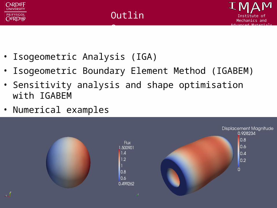
• Isogeometric Analysis (IGA)
• Isogeometric Boundary Element Method (IGABEM)
• Sensitivity analysis and shape optimisation with IGABEM
• Numerical examples
Outline
Institute of Mechanics and Advanced Materials
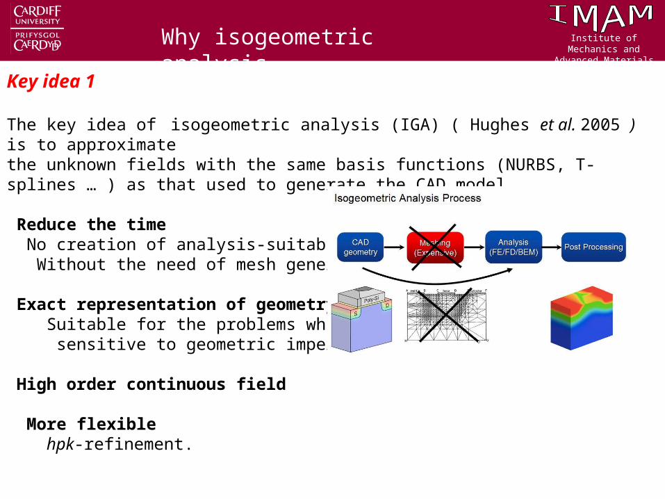
Key idea 1
The key idea of isogeometric analysis (IGA) ( Hughes et al. 2005 ) is to approximate the unknown fields with the same basis functions (NURBS, T-splines … ) as that used to generate the CAD model.
Reduce the time No creation of analysis-suitable geometry; Without the need of mesh generation.
Exact representation of geometry Suitable for the problems which are sensitive to geometric imperfections.
High order continuous field
More flexible hpk-refinement.
Why isogeometric analysis

Institute of Mechanics and Advanced Materials
1. Knot vector:
a non-decreasing set of coordinates in the parametric space.
Where n is the number of basis functions,
i is the knot index and p is the curve degree,
2. Control points:
3. NURBS basis function:
1
C B n
i ,p ii
N .
NURBS curve
1 2 1{ , , , }n p
Institute of Mechanics and Advanced Materials
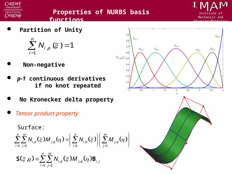
Properties of NURBS basis functions
Partition of Unity
Non-negative
p-1 continuous derivatives if no knot repeated
No Kronecker delta property
Tensor product property Surface:
1 1 1 1
n m n m
i ,p j ,q i ,p j ,qi j i j
N M N M
,1
( ) 1n
i pi
N
1 1
,
S B n m
i ,p j ,q i , ji j
N M

Institute of Mechanics and Advanced Materials
Challenges
domain parameterization,
Surface representation Domain representation

Institute of Mechanics and Advanced Materials
Key idea 2:
Isogeometric Boundary Element Method (IGABEM) (Simpson, et al. 2011).
The NURBS basis functions are used to discretise Boundary Integral Equation
(BIE). Recently this work is extended to incorporate analysis-suitable T-splines.
Reasons:
1. Representation of boundaries;
2. Easy to represent complex geometries.
IGABEM

Institute of Mechanics and Advanced Materials
Regularised form of boundary integral equation for 2D linear elasticity
where and are field point and source point respectively, and are
displacement and traction around the boundary, and are fundamental
solutions.
The geometry is discretised by:
The field is discretised by:
IGABEM formulation

Institute of Mechanics and Advanced Materials
IGABEM formulation
In Parametric space
Integration in parent element
Matrix equation

Institute of Mechanics and Advanced Materials
1. Collocation point (Greville abscissae)
2. Boundary condition
Collocate on the prescribed boundary
3. Integration
High order Gauss integration
Special techniques for IGABEM

Institute of Mechanics and Advanced Materials
Nuclear reactor
Institute of Mechanics and Advanced Materials
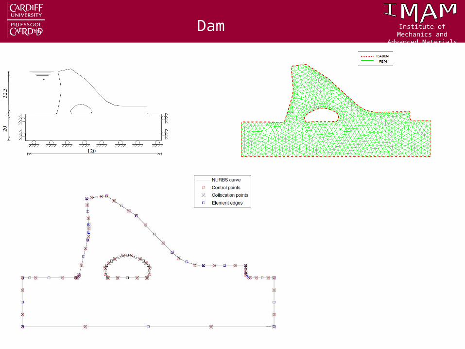
Dam

Institute of Mechanics and Advanced Materials
Propeller

Institute of Mechanics and Advanced Materials
The advantages of IGABEM for shape optimisation.
More efficient
An interaction with CAD:
1. Analysis can read the CAD data directly
without any preprocessing.
2. Analysis can return the data to CAD
without any postprocessing.
More accurate
Design velocity field is exactly obtained for
gradient-based shape optimisation.
IGABEM shape optimisation

Institute of Mechanics and Advanced Materials
• Governing equations in parametric space, which can be viewed as material coordinate system
• Differentiate the equation w.r.t. design variables (implicit differentiation)
• Discretise the derivatives of displacement and traction using NURBS basis
• Finally
IGABEM sensitivity analysis

Institute of Mechanics and Advanced Materials
Sensitivity Propagation
h-refinement algorithm is also suitable for shape derivatives refinement, but need to convert NURBS in to B-splines in

Institute of Mechanics and Advanced Materials
Pressure cylinder problem
Design variable is large radius b

Institute of Mechanics and Advanced Materials
Infinite plate with a hole
Design variable is radius R

Institute of Mechanics and Advanced Materials
Cantilever Beam
Design curve is AB
Minimise the area without violating von Mises stress criterion
Institute of Mechanics and Advanced Materials
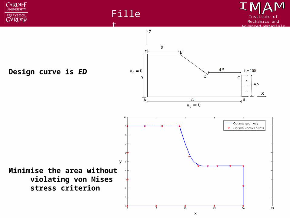
Fillet
Design curve is ED
Minimise the area without violating von Mises stress criterion

Institute of Mechanics and Advanced Materials
Conclusions• An isogeometric boundary element method (IGABEM) has been introduced.
• IGABEM can suppress the mesh burden and interact with CAD.
• IGABEM has been applied to gradient-based shape optimisation.
• IGABEM is more efficient and accurate for analysis and optimisation
Future work:• Topology optimisation with IGABEM Easy to handle topology optimisation compared to IGAFEM Easy to implement with the help of topology derivatives • T-spline based IGABEM for 3D shape optimisation Local refinement Analysis suitable and flexible to construct the complex geometry
Conclusions

Institute of Mechanics and Advanced Materials

Institute of Mechanics and Advanced Materials
TJR Hughes, JA Cottrell, and Y Bazilevs. Isogeometric analysis: CAD, finite elements, NURBS, exact geometry and mesh refinement. Computer Methods in Applied Mechanics and Engineering, 194(39-41):4135-4195, 2005.
T Greville. Numerical procedures for interpolation by spline functions. Journal of the society for Industrial and Applied mathematics: Series B, Numerical Analysis, 1964.
R Johnson. Higher order B-spline collocation at the Greville abscissae. Applied Numerical Mathematics, 52:63-75, 2005.
Les Piegl and W Tiller. The NURBS book. Springer, 1995.
RN Simpson, SPA Bordas, J Trevelyan and T Rabczuk. An Isogeometric boundary element method for elastostatic analysis. Computer Methods in Applied Mechanics and Engineering. 209-212 (2012) 87–100.
References