institute of publishing bioinspiration iomimetics … · 2020-03-21 · active articulation for...
TRANSCRIPT

INSTITUTE OF PHYSICS PUBLISHING BIOINSPIRATION amp BIOMIMETICS
Bioinsp Biomim 1 (2006) 52ndash61 doi1010881748-318212003
Active articulation for future spaceapplications inspired by the hydraulicsystem of spidersC Menon1 and C Lira2
1 Advanced Concepts Team European Space Agency ESTEC Keplerlaan 1 2201 AZ NoordwijkThe Netherlands2 Centre of Mechatronics Science Studies and Information University of Technology Kaunas Lithuania
E-mail carlomenonesaint and infoVSFprojectcom
Received 21 April 2006Accepted for publication 26 July 2006Published 17 August 2006Online at stacksioporgBB152
AbstractThis paper presents and discusses a novel mechanism which was conceived taking inspirationfrom the micro-hydraulic system used by spiders to extend their legs The mechanism has thepotential to be used in future space applications although the harsh space conditions and inparticular outgassing should be carefully addressed in the design of a space-qualified modelThe new system has one degree of freedom and is actuated by a pressurized fluidic systemThe prototype which has been designed simulated built and tested is of compact size andpresents a repeatable behaviour The relation between pressure and rotation is approximatelylinear The mechanism is suitable for a modular configuration in which several elastic jointmodules are joined together This modular configuration allows large rotations and does notincrease the complexity of the actuation A single module bends about 18 when the pressureof the working fluid is 12 MPa
1 Introduction
Most animals have opposing muscles to articulate their joints(6) flexors which are used to bend the limbs and (2) extensorswhich straighten the joints In spider legs however somejoints do not have extensors as a peculiar hydraulic system isused for this purpose Spiders have their legs directly attachedto a main body called the prosoma as shown in figure 1 Theprosoma similarly to a pump can increase the fluid pressureinside the spider by contracting and expanding When thepressure is increased the working fluid flows inside the limbsand extends some joints of the spiderrsquos legs
This paper proposes and analyses a novel mechanism[1] which takes inspiration from spider limb joints and canbe efficiently integrated in lightweight structures for spaceuse The paper is organized as follows this section presentsthe motivations that led us to study inflatable systems forspace applications and highlights the main challenges andinherent issues of this topic section 2 investigates the spiderhydraulic system and presents research results obtained so
far section 3 defines the problem that was studied section 4describes the novel mechanism called Smart Stick whichwas conceived section 5 presents the design of the SmartStick section 6 presents the fabrication procedure used toobtain a prototype section 7 discusses the modelling andthe numerical simulations performed section 8 describesthe optical test bench used for the tests and presents theexperimental characterization of the Smart Stick section 9presents discusses and compares numerical and experimentalresults section 10 proposes future improvements in the designand identifies the next development steps Section 11 drawsconclusions of the research performed and of the resultsobtained
11 Inflatable systems
Space applications require structures mechanisms andsystems that are able to fulfil challenging tasks while keepingtheir volumes and masses to a minimum Gossamer structuresare already a reality in the space field and research is
1748-318206020052+10$3000 copy 2006 IOP Publishing Ltd Printed in the UK 52
A bio-inspired fluidic actuator for future space applications
Figure 1 Spidersrsquo subsystems of interest for the design of abio-inspired fluidic mechatronic system
giving new results thanks to the use of innovative materialsand technologies The Echo Balloon the Inflatable TorusSolar Array Technology (ITSAT) the Inflatable AntennaExperiment (IAE) and the Inflated-Spherical-Wheel Rover arejust a few examples of space inflatable still structures whichhave been tested in the past few years [3ndash9]
The use of inflatable mechanisms has some limitationsdue to the harsh space environment Charged and high-energyparticles gas loss solar ultraviolet and space radiation play animportant role in the selection and development of inflatablematerials
In terrestrial use pneumatic systems are often used foractuation Pneumatic actuators are generally very fast butdifficult to control Often a lsquobangndashbangrsquo control is usedDouble-acting cylinders are advisable for differential pressurecontrol In this case however the complexity cost and weightare increased Muscle bio-inspired pneumatic actuators firstconceived for use in artificial limbs in the 1950ndash1960s [10]are now used and commercialized for anthroform bio-roboticarm development An example of bio-inspired pneumaticactuators is the McKibben actuator [11] This simple deviceconsists of a braided sleeve usually made of nylon wireswhich contains a deformable bladder Compressed air is usedto inflate the bladder and since the strand is less extensible anaxial contraction of the actuator occurs They are characterizedby a high strength-to-weight ratio but the need for storage ofcompressed air in autonomous systems limits their use
12 Hydraulic mechanisms
Literature on space inflatable systems that use liquid fluids asthe inflating means is not as common as that for gas inflatablesystems Hydraulic mechanisms are generally not chosen foron-orbitplanets applications [5] for several reasons eg
1 liquid fluids outgas2 liquids are temperature sensitive3 liquids are heavier than gases4 hydraulic pumps induce vibrations and cavitations can
occur
Table 1 Planet characteristics
T (C)
Range Average Pressure (kPa) Composition
Mercury [minus173 427] 179 None K (317)Venus [minus44 500] 464 9320 CO2 (gt964)Earth [minus69 58] 7 101 N2 (gt78)Mars [minus140 20] minus63 0699ndash0912 CO2 (gt953)Jupiter [minus163 ] minus121 Varies with depth H2 (gt81)Saturn [minus191 ] minus130 Varies with depth H2 (gt93)Uranus [minus214 ] minus205 Varies with depth H2 (gt82)Neptune [minus223 ] minus220 Varies with depth H2 (gt84)Pluto [minus240 minus218] minus229 None CH3
The use of liquid fluids can however lead to newsolutions and applications if the space hazards are carefullyconsidered The use of closed systems (no exchange withthe environment) and low outgassing fluids characterized bylow sensitivity to temperature changes can lead to the designof hydraulic space-qualified systems Inflatable systemscould also be designed by controlling the elasticity of theliquid tank Miniaturized hydraulic mechanisms can be ofparticular interest In fact space applications do not generallyrequire high force actuators while mass must always beminimized Taking advantage of their high strength-to-weightratio miniaturized hydraulic mechanisms could represent acompelling new approach
13 The challenging space environment
A fundamental challenge for the use of inflatable spacemechanisms is the space environment Temperature rangepressure and atmospheric (if any) composition must beconsidered when a space mechanism is designed Table 1summarizes salient characteristics of some planets of the solarsystems [4]
Outgassing and fluid leakage are important issues whichmust be considered during the design phase of spacemechanisms Considering for instance a probe on the Marssurface the pressure is in the range 07ndash09 kPa whereason Venus there is a pressure of 9320 kPa Mars has an averagetemperature of minus63 C whereas Venus is at about 464 Cwhich could be prohibitive for conventional inflatable spacearchitectures The design of inflatable systems must thereforecarefully take into account the surrounding operationalenvironment
In the framework of this study which is at an early stagethe Earth environment was considered because prototypingwas considered a necessary step for the mechanism synthesisModifications must therefore be introduced when a differentenvironment is considered
2 Leg extension system in spiders
The legs of several arthropods (arachnids diplopodschilopods pauropods) have joints that can be classified ashinge joints [13 14] The anatomical form of the jointoften does not permit the presence of antagonistic extensorswhich are often substituted by hydraulic systems The empty
53
C Menon and C Lira
spaces in between muscles and skeleton are usually filled withhaemolymph (spiderrsquos blood) This pressurized liquid is usedas a means to pressurize the spiderrsquos joints Thin channelssupply haemolymph to peripheral segments through the leg
In 1959 Parry and Brown carefully investigated spiderlegs and their pressurized mechanism They showedexperimentally that the active extension which occurs at thehinge joints of the Tegenaria legs is based on a hydraulicmechanism They measured the internal pressure in theleg of an intact spider established an empirical relationbetween the internal pressure and joint torque and performedmeasurements of the actual torque developed when a spideraccelerates a mass attached to its leg
Many methods used to measure the leg inner pressuretake advantage of the thin flexible articular membranes at thejoints For instance Parry and Brown used a sleeve sealed overthe leg The pressure in the sleeve was slowly raised until themembrane collapsed [15] Blickhan and Barth in 1985 used atransducer with a tip smaller than the leg blood channels Themeasurement system was mounted on freely moving spidersand also connected to several points of the hunting spiderCupiennius salei by means of tethers with negligible weight
The mechanism for leg extension is now well documentedfor various spiders and whipscorpions [18 19] Aphonopelmahave an inner pressure of about 53ndash8 kPa [22] and in walkingMastigoproctus the fluid arrives at a pressure up to 9 kPa[21] In 1985 Blickhan and Barth measured up to 70 kPaon Cupiennius salei legs (130 kPa during autonomy) Severalhypotheses have been supported by experiments to explainhow the prosoma natural pump works [2 15 21ndash23]
Biologists were also able to measure the torque exertedby pressurized limb joints It was shown that the torqueincreases approximately linearly with pressure [18] Thetibiandashbasitarsus joints of the tarantula Aphonopelma exert20ndash74 mN mm when a pressure over the range 25ndash98 kPais provided Recent research reported high-resolution imagesusing transmission electron microscopy (TEM) which showcross sections of spider legs By studying the legs ofLeiobunum nigripes Guffey [7] eg observed the presenceof a single tendon within a haemocoelic space connecting thetarsal claw to the claw-flexing musculature of the tibia Thespider mechanism is also able to provide explosive force Highpressure can extend the rear legs allowing spiders to jump[15 16]
There have not been many attempts to design engineeringmodels of spider joints One of the most remarkable workswas done by Schworer Kohl and Menz [20] Their mechanismwas actuated by nitrogen and was able to lift a weight of82 mN The mechanism was built using extremely expensiveequipment and processes (eg LIGA) suitable only for micro-systems
3 Problem definition
Figure 2 shows a flow diagram of the mechanism to bedesigned A command is given to an actuator whichcompresses the working fluid The fluid flows through amicro-pipeline and reversibly deforms an inflatable structure
Figure 2 Flow diagram
Figure 3 Fluidic actuator
that produces a rotation of a flexible joint The joint rotationis fed back by a sensor in order to correct the command
The system should have a closed fluid system in order toreduce leaking problems and outgassing phenomena whichare compelling challenges for space mechanisms There areno limitations on the working fluid which could be a gas or aliquid
The synthesis of the novel bio-inspired mechanismdescribed in this paper focuses on the inflatable structureembedded in a flexible joint The sensor unit and themechanism used to compress the working fluid are notanalysed at this stage The mechanism is intended foroperation in the space environment However the breadboarddescribed in this paper was designed for terrestrialexperiments
Besides space and robotic applications the proposedfluidic actuator could also be used in wearable equipmenteg smart bra [12]
4 Smart Stick
The novel conceived mechanism called lsquoSmart Stickrsquo is basedon the use of a miniaturized tube (outside diameter 1 mm)The tube can be embedded into flexible structures to obtainintegrated systems Figure 3 shows the shape and dimensionsof the miniaturized pipe obtained by plastic deformation Thepart of the mini-tube having elliptical shape constitutes thelsquofluidic actuatorrsquo of the system Figure 4 shows the tubeembedded in the lsquoSmart Stickrsquo structure The actuator actsupon hydraulic principles and the effects of the pressurizationare stiffness variation and bending force generation in thestructure
54
A bio-inspired fluidic actuator for future space applications
Figure 4 Elastic joint with two joint actuators
The actuator manufacturing process can be repeated alongthe whole tube The repeated process allows easy fabricationof a series of miniaturized fluidic actuators By folding anddeforming the mini-tube mechanical connectors are avoidedmaking the system simple reliable and light
The design was conceived taking into account themanufacturing process and the robustness of the actuator Thecase of a bi-phase fluid was also considered The system issuitable for a closed loop control which regulates the pressurep (effort variable) in the actuator
5 Prototype design
The length of the actuators which were designed was 30 mmThe elliptical section of the mini-tube (see figure 3) wasrepeated along the tube every 15 mm The tube was bentbetween each two elliptical sections in order to convey theworking fluid to different joints Figure 5 shows the rotationof a mechanism module induced by the deformation of thepressurized tube
The pressurized tube expands bending the inner metal foilalong the bay Eleven rigid spacers are glued to each side ofthe metal foil to ensure that each joint actuator works properlyIn order to guarantee a controllable bending variation of thejoint in both directions the Smart Stick module is symmetricalwith respect to its longitudinal axis
Figure 5 Smart Stick module rigid spacer (blue) metal foil (red) fluidic actuator (green)
Figure 6 Prototype with two series of fluidic actuators and tenelastic joints
Multiple modules of the Smart Stick can be embeddedinto one structure Figure 6 shows both the design and theprototype which was built This prototype has 10 elastic jointsand 20 fluidic actuators The action of actuators on the sameside of the mechanism makes it bend with a constant curvaturewhen no external loads are applied By changing the positionof simultaneously actuated joint actuators different shapes ofthe Smart Stick can be obtained
In order to assess the performance of the prototype acustom-made pump syringe used to increase the pressure ofthe working fluid inside the Smart Stick was designed andbuilt Figure 7(A) shows the three-dimensional model of thepump syringe A micrometre screw was used to regulate the
55
C Menon and C Lira
Table 2 Characteristics of the components of the Smart Stick system
Component Material Dimensions
Flexible joint (foil) X12CrNi177 (AISI 301) Length 94 plusmn 01 mmE = 193 GPa Width 30 plusmn 01 mmDensity = 8 g cmndash3 Thickness 01 plusmn 0004 mmTensile strength ultimate = 1280 MPaTensile strength yield = 965 MPaElongation at break = 9Modulus of elasticity = 193 GPa
Spacers Aluminium alloy AlndashMg series 6000 lsquoCrsquo shape (8 plusmn 01) mm times (2 plusmn 01) mmE = 70 GPa Thickness 1 plusmn 005 mm
Mini-tubes (fluidic actuators) AKEMA Poly Block Ammide (Pebax Rcopy 6333) Outer diameter 1 plusmn 002 mmE = 276 MPa Inner diameter 05 plusmn 002 mm (see figure 3)
(A) (B)
Figure 7 Screw actuated pump syringe used during testing toincrease the pressure of the working fluid
pressure of the syringe which was sealed to the micro-tube ofthe Smart Stick Figure 7(B) shows the screw actuated pumpsyringe built and then used for experimental tests
6 Fabrication
The prototype was built using the components described intable 2 The procedure to fabricate the prototype is as follows
1 The spacers which had a lsquoCrsquo shape were accurately gluedto a flexible joint (metallic foil)
2 The elliptical shape of the fluidic actuators was obtainedby compressing the mini-tubes between two parallelsurfaces
3 The fluidic actuators were positioned between twoconsecutive spacers Friction and compressive forceswere sufficient to keep the actuators in their positions
The data concerning the flexible joint which is theelement that mainly influences the linear elastic behaviourand stiffness of the Smart Stick were experimentally tested byusing the set-up shown in figure 8
Figure 8 Set-up for the characterization of the flexible joint (metalfoil) of the Smart Stick
7 Smart Stick modelling
The performance of the Smart Stick was numericallyassessed by modelling the mechanism Nonlinear numericalsimulations were performed using Marc a finite-elementmethod code Figure 9 shows the model of one Smart Stickmodule with just one fluidic actuator an elliptical tube (green)is set between two spacers (blue) which are attached by aflexible joint (red) The mesh of the model is also shown infigure 9 (white)
Positions of the nodes on the right-hand side of the modelwere fixed (black lines) Contact constraints were imposedat the tubespacer and tubejoint interfaces Nodes betweenthe spacers and the flexible joint were merged The two orangedots in figure 9 represent two nodes shared by the elliptictube and the spacers A constant pressure was imposed insidethe elliptical tube Figure 10 shows the deformation of thefluidic mechanism when the tube is pressurized
A sensitivity analysis was performed in order tounderstand the critical parameter of the design Dimensionsand material properties of the flexible joint (red in figure 9) playa fundamental role by defining the relation between rotation ofthe joint and inner pressure in the tube The linear behaviour ofthe flexible joint in large displacement ranges implies a linearbehaviour of the mechanism
A complete model including fluidic actuators on bothsides of the flexible joint was also designed Figure 11 showsthe deformation of a Smart Stick with six modules The total
56
A bio-inspired fluidic actuator for future space applications
Figure 9 Two-dimensional model
Figure 10 Visual deformation of one module
(A) (B)
Figure 11 Model of six Smart Stick modules Colours give a qualitative value of the deformations
Figure 12 Elastic joint in vertical position with only one fluidicactuator in the bay
rotation of the system increases linearly with the number of themodules used In this complete module the fluidic actuators atthe bottom of figure 11(A) act as antagonist muscles As a notnegligible force is requested to compress them (see squeezedantagonist fluidic actuators in figure 11) the rotation of theSmart Stick is expected to be reduced On the other handantagonist actuators allow negative rotations of the system asshown in figure 11(B)
8 Experimental characterization and optical testbench
A Smart Stick module was tested in order to obtain the relationbetween fluid pressure and joint rotation (water was used asthe working fluid) An empirical model is useful to predictthe behaviour of the Smart Stick in the control algorithmFigure 12 shows the elastic joint in vertical configurationobtained by fixing the rigid spacer (n minus 1) A verticalconfiguration was used to reduce the influence of thegravitational force
Gravitational forces do not cause appreciabledeformations as the inner metal foil has high flexuralstiffness around an axis perpendicular to the axis of jointrotation During the experiment no external loads wereapplied to the elastic joint (except gravity)
57
C Menon and C Lira
Figure 13 Sketch of the test bench
An optical test bench which is schematically shownin figure 13 was used to perform the experimentalcharacterization The first pair of rigid spacers was fixedand referred to the incoming ray trace Figure 13 shows thecircular mirror fixed on the second pair of rigid spacers Inthe nominal horizontal position the mirror is perpendicular tothe rays coming from a laser source fixed to a screen frameDepending on the mirror angle the reflected ray trace moveson the screen by a measured distance M
81 Test bench overall dimensions
The distance (D) between the mirror and the laser source(see figure 13) is 2 m The uncertainty associated with Dwith a level of confidence of 683 is δD = 15 mm Theuncertainty in the direct measurement of deflection distance(M) with a level of confidence of 683 is δM = 05 mm
The rotation of the Smart Stick module was computed bythe following equation
θ = 1
2arctg
(M
D
) (1)
For small angles the previous equation can be simplified
θ asymp 1
2
(M
D
) (2)
The uncertainty δθ associated with the angle θ can be computedas follows
δθ = f (θM) =radic[(
partθ
partM
)middot δM
]2
+
[(partθ
partD
)middot δD
]2
(3)
Substituting equation (2) in equation (3) yields
δθ =radic[(
1
2
1
D
)middot δM
]2
+
[(minus1
2
M
D2
)middot δD
]2
(4)
Considering the assumption of the model and additionalvariables that were neglected the uncertainty iθ of the angle θ
can be assumed to be equal to 03 (997 level of confidence)Figure 14 shows the experimental set-up (two fluidic actuatorsare represented)
Figure 14 Elastic joint in test bench
Figure 15 Stresses caused by the deformation of one single fluidicactuator module induced by a pressure of 12 MPa In the legendthe values are in MPa
The uncertainty in the effort variable p (pressure of theworking fluid) was ip = 0013 MPa (997 level of confidence)as declared in the calibration certificate of the pressure gaugewhich was used
9 Numerical and experimental results
Numerical simulations were extremely useful to predict theperformance and accurately define the geometry of the SmartStick Figure 15 shows the stresses in a single fluidicactuator module due to a deformation induced by a pressure of12 MPa Using the von Mises criterion the maximum stresswas 671 MPa localized in the flexible joint This value is belowthe tensile yield strength of the AISI 301 austenitic stainlesssteel foil (965 MPa) The use of a thinner flexible joint isbelieved to increase the structural stresses while increasingthe Smart Stick rotation for a fixed fluid pressure
Different quasi-static simulations of a single module of theSmart Stick were performed while changing the pressure valueinside the fluidic actuator Dimensions and material describedin section 5 were used The numerical model foresees good
58
A bio-inspired fluidic actuator for future space applications
0
1
2
3
4
0 02 04 06 08 1 12
Inner Pressure (MPa)
Ela
stic jo
int
rota
tio
n (
de
g)
Figure 16 Numerical prediction of one Smart Stick module withonly one fluidic actuator Red dots experimental results Blue linelinear fitting curve
1
2
3
5
4
0 02 04 06 08 1 12
Inner Pressure (MPa)
Ela
stic jo
int
rota
tio
n (
de
g)
Experimental dataBest fit
Figure 17 Experimental results of one Smart Stick module withonly one fluidic actuator Red line experimental results Blue linelinear fitting curve
performance of the system as presented in figure 16 Thisfigure shows that the rotation of a module is linearly changingwith the pressure inside the fluidic actuators (the red dotsrepresent single quasi-static numerical simulations the blueline is a fitting curve)
Several experimental tests were also performed using theSmart Stick prototype in order to characterize its behaviourFigure 17 shows that the rotation of the joint can beapproximated with a linear function (blue line) Figure 17concerns the use of one module of the Smart Stick havingonly one fluidic actuator embedded in the system Figure 18shows experimental results for eight cycles using the same jointmodule A fitting of the experimental data was performed inorder to obtain an empirical equation that could be used forcontrol purposes
θ = θ(p) = 357p + 013 (5)
where the angle is in degrees and the pressure in MPa Theuncertainty (997 level of confidence) associated with theslope of the function is plusmn013 MPandash1 and that associated withthe intercept is plusmn024
Figures 17 and 18 show the behaviour of the Smart Stickthat was correctly predicted by the numerical simulations(figure 16) Comparison of numerical end experimental testsproves both the correctness of the model and the quality of the
1
2
3
5
4
0 02 04 06 08 1 12
Inner Pressure (MPa)
Ela
stic jo
int
rota
tio
n (
de
g)
Uncertainty assess
plusmn 03
plusmn 0013
Single joint actuatorin the elastic joint
Figure 18 Multiple cycles of one Smart Stick module (only onefluidic actuator)
Figure 19 Stresses caused by the deformation of the Smart Stickinduced by a pressure of 12 MPa In the legend the values are inMPa
Figure 20 Strains caused by the deformation of the Smart Stickinduced by a pressure of 12 MPa In the legend the values are inpercentage
experimental set-up In addition figures 17 and 18 confirmthe high performance of the Smart Stick breadboard and showits potential for future applications
Numerical predictions of a complete Smart Stick werealso estimated by means of numerical simulations Stressesinduced on modules made of counteracting fluidic actuators areshown in figure 19 In this case the presence of the antagonistactuators reduces the bending stresses The maximum stresspick is still concentrated in the flexible joint and measures
59
C Menon and C Lira
0
1
2
0 02 04 06 08 1 12
Inner Pressure (MPa)
Ela
stic
join
t ro
tatio
n (
de
g)
Figure 21 Numerical prediction of one Smart Stick module withonly one fluidic actuator Blue dots experimental results Red linelinear fitting curve
0
1
2
02 04 06 08 1 12Inner Pressure (MPa)
Ela
stic
join
t ro
tatio
n (
de
g)
Pair of joint actuatorsin the elastic joint
Uncertainty assess
plusmn 03
plusmn 0013
Figure 22 Multiple cycles of one Smart Stick module (two fluidicactuators)
373 MPa Figure 20 shows that for the same pressure loadsthe maximum strain is reached by the compressed fluidicactuators The maximum value is about 4 which is in therange of deformations allowed by the material used for themicro-tubes (AKEMA Poly Block Ammide)
Quasi-static simulations of a single Smart Stick moduleequipped with opposing fluidic actuators were also performedand figure 21 shows the results The system still has a linear
Figure 23 Sketch of a closed fluid loop
behaviour which is guaranteed by the linear elasticity of theflexible joint Compared to the case shown in figure 16 thedeformation predicted by figure 21 is lower as an additionalforce is in this case required in order to compress the antagonistfluidic actuator
This predicted performance was validated byexperimental tests carried out considering a module ofthe Smart Stick equipped with two antagonistic fluidicactuators Figure 22 shows the experimental results ofeight pressurizationdepressurization cycles A fitting ofthe experimental data was performed in order to obtain anempirical equation that could be used for control purposes
θ = θ(p) = 149p + 004 (6)
where the angle is in degrees and the pressure in MPaThe uncertainty associated with the slope of the function isplusmn011 MPandash1 and uncertainty associated with the intercept isplusmn015
The consistency of the numerical prediction shown infigure 21 and the experimental results of figure 22 confirms thereliability of both the numerical model and the experimentalset-up
10 Future improvements and designs
In order to increase the performance of the Smart Stick acareful selection of the material employed is needed Theuse of aerogels and lighter and more flexible materials for thespacers is being considered Improvement in the design willfocus on multiple parallel mini-tubes which can bring moreflexibility to the system
The fundamental next step necessary to obtain a completemechatronic breadboard for space applications will be therealization of the multi-module Smart Stick incorporating aclosed fluid loop Figure 23 shows a sketch which presentsthe concept idea of two symmetric closed fluid loops in aspider inspired configuration In this figure the controllersends the commands to an actuator mechanism that squeezesan expandable reservoir The pressure of the working fluidwhich is confined inside a closed loop is thus increased Amicro-pipe links the reservoir to the Smart Stick which changes
60
A bio-inspired fluidic actuator for future space applications
its shape according to the pressure values The rotation ofthe flexible joint in which the Smart Stick is integrated ismeasured by embedded sensors that feed back the signal tothe controller
The use of a closed fluid loop which allows overcomingleakage and outgassing issues is considered to be a criticalpoint for a successful hydraulic space mechanism Futurework will be focused on the development of a completeclosed loop mechatronic system and particular attention willbe paid to the actuation system This could include smartmaterials such as piezoelectric materials shape memory alloysand electro-active polymers [17 24] In particular dielectricelectro-active polymers have promising characteristics for thisapplication as they exert considerable forces in a wide rangeof large deformations and can be space qualified Magneto-restrictive fluids will also be evaluated in order to improve thetorque performance of the system
11 Conclusions
A novel flexible joint with an embedded fluidic system ispresented in this paper The novel mechanism is inspired bythe joints and the hydraulic closed system of spiders Theproposed mechanism can be fabricated using traditional andinexpensive processes and methodologies The modularityof the mechanism can be used to design joints for largedisplacements The system was numerically simulated inorder to appropriately design the geometry and to predict itsquasi-static characteristics A miniaturized prototype was alsobuilt and tests were performed by using an optical test benchNumerical and experimental results are consistent and showthe feasibility of the design Improvements of the systemare also suggested and a closed fluid loop configuration isproposed for future investigations
Acknowledgments
The work was carried out thanks to NATO grant awarded toCristian Lira (grant no NATO-CNR 21536) The authorsalso thank Susanna Valpreda for her valuable support in thebibliographic review VICI AG International for providingcomponents of the screw actuated pump syringe Mario Vanninfor the characterization of the flexible metal foil and Devis andRomeo Facchin for their support in the manufacturing part
References
[1] Menon C and Lira C 2006 Spider-inspired embedded actuatorfor space applications AISBrsquo06mdashAdaptation in Artificialand Biological Systems (Bristol)
[2] Anderson J F and Prestwich K N 1975 The fluid pressurepumps of spiders (Chelicerata Araneae) Z Morphol Tiere81 257ndash77
[3] Bar-Cohen Y 2000 Electroactive polymers as artificialmusclesmdashcapabilities potentials and challenges Robotics2000 and Space 2000 (Albuquerque NM 28 Februaryndash2March)
[4] Barik M E 2000 Planetary Handbook (Cambridge CambridgeUniversity Press)
[5] Benaroya H Bernold L and Chua K M 2002 Engineeringdesign and construction of lunar bases J Aerospace Eng15 33ndash45
[6] Blickhan R and Barth F G 1985 Stains in the exoskeleton ofspiders J Comp Physiol 157 115ndash47
[7] Guffey C Townsend V R Jr and Felgenhauer B E 2000External morphology and ultrastructure of the prehensileregion of the legs of Leiobunum nigripes (ArachnidaOpiliones) J Arachnol 28 231ndash6
[8] Kitagawa A Tsukagoshi H and Segawa M 2000 Proposal of aconnective type active hose with many degrees of freedomfor the rescue operation 6th Triennial Int Symp on FluidControl Measurement and Visualization (SherbrookeCanada 2000)
[9] Jenkins C H M 2001 Gossamer spacecraft membrane andinflatable structures technology for space applicationsProg Astronaut Aeronaut 191 481ndash501
[10] Knight R and Nehmzow U 2002 Walking robots a survey anda research proposal Technical Report CSM-375 (Universityof Essex)
[11] Chou C P and Hannaford B 1994 Static and dynamiccharacteristics of McKibben pneumatic artificial musclesProc IEEE Int Conf on Robotics and Automation(San Diego CA May 1994)
[12] Lira C Angrilli F and Debei S 2002 Variable structure fabricand uses for it Patent Document WO02099172
[13] Manton S M 1958 Evolution of arthropodan locomotorymechanisms part 6 J Unn Soc (Zool) 43 488ndash556
[14] Manton S M 1958 Hydrostatic pressure and leg extension inarthropods Ann Mag Nat Hist (Series 13) 1 161ndash82
[15] Parry D A and Brown R H J 1959 The Hydraulic Mechanismof the Spider Leg (Department of Zoology University ofCambridge
[16] Parry D A and Brown R H J 1959 The jumping mechanism ofsalticid spiders J Exp Biol 36 654ndash64
[17] Rossi D Carpi F Jeronimidis G Gaudenzi P Tralli AZolesi V and Ayre M 2004 Electroactive Polymers forActuation and Sensing in Space Applications (IAC AIAAVancouver Canada)
[18] Sensenig A T and Shultz J W 2003 Mechanics of cuticularelastic energy storage in leg joints lacking extensor musclesin arachnids J Exp Biol 206 771ndash84
[19] Sensenig A T and Shultz J W 2004 Elastic energy storage inthe pedipalpal joints of scorpions and sun-spiders(Arachnida Scorpiones Solifugae) J Arachnol 32 1ndash10
[20] Schworer M Kohl M and Menz W 1998 Fluidic microjointsbased on spider legs Conf on New Actuators (Bremen)
[21] Shultz J W 1991 Evolution of locomotion in Arachnida thehydraulic pressure pump of the giant whipscorpionMastigoproctus giganteus (Uropygi) J Morphol210 13ndash31
[22] Stewart D M and Martin A W 1974 Blood pressure in thetarantula Dugesiella hentzi J Comp Physiol 88 141ndash72
[23] Wilson R S and Bullock J 1973 The hydraulic interactionbetween prosoma and opisthosoma in Amaurobius ferox(Chelicerata Araneae) Z Morphol Tiere 74 221ndash30
[24] Menon C Ayre M and Ellery A 2006 Biomimetics a newapproach for space systems design ESA Bull 125 20ndash6
61
- 1 Introduction
-
- 11 Inflatable systems
- 12 Hydraulic mechanisms
- 13 The challenging space environment
-
- 2 Leg extension system in spiders
- 3 Problem definition
- 4 Smart Stick
- 5 Prototype design
- 6 Fabrication
- 7 Smart Stick modelling
- 8 Experimental characterization and optical test bench
-
- 81 Test bench overall dimensions
-
- 9 Numerical and experimental results
- 10 Future improvements and designs
- 11 Conclusions
- Acknowledgments
- References
-

A bio-inspired fluidic actuator for future space applications
Figure 1 Spidersrsquo subsystems of interest for the design of abio-inspired fluidic mechatronic system
giving new results thanks to the use of innovative materialsand technologies The Echo Balloon the Inflatable TorusSolar Array Technology (ITSAT) the Inflatable AntennaExperiment (IAE) and the Inflated-Spherical-Wheel Rover arejust a few examples of space inflatable still structures whichhave been tested in the past few years [3ndash9]
The use of inflatable mechanisms has some limitationsdue to the harsh space environment Charged and high-energyparticles gas loss solar ultraviolet and space radiation play animportant role in the selection and development of inflatablematerials
In terrestrial use pneumatic systems are often used foractuation Pneumatic actuators are generally very fast butdifficult to control Often a lsquobangndashbangrsquo control is usedDouble-acting cylinders are advisable for differential pressurecontrol In this case however the complexity cost and weightare increased Muscle bio-inspired pneumatic actuators firstconceived for use in artificial limbs in the 1950ndash1960s [10]are now used and commercialized for anthroform bio-roboticarm development An example of bio-inspired pneumaticactuators is the McKibben actuator [11] This simple deviceconsists of a braided sleeve usually made of nylon wireswhich contains a deformable bladder Compressed air is usedto inflate the bladder and since the strand is less extensible anaxial contraction of the actuator occurs They are characterizedby a high strength-to-weight ratio but the need for storage ofcompressed air in autonomous systems limits their use
12 Hydraulic mechanisms
Literature on space inflatable systems that use liquid fluids asthe inflating means is not as common as that for gas inflatablesystems Hydraulic mechanisms are generally not chosen foron-orbitplanets applications [5] for several reasons eg
1 liquid fluids outgas2 liquids are temperature sensitive3 liquids are heavier than gases4 hydraulic pumps induce vibrations and cavitations can
occur
Table 1 Planet characteristics
T (C)
Range Average Pressure (kPa) Composition
Mercury [minus173 427] 179 None K (317)Venus [minus44 500] 464 9320 CO2 (gt964)Earth [minus69 58] 7 101 N2 (gt78)Mars [minus140 20] minus63 0699ndash0912 CO2 (gt953)Jupiter [minus163 ] minus121 Varies with depth H2 (gt81)Saturn [minus191 ] minus130 Varies with depth H2 (gt93)Uranus [minus214 ] minus205 Varies with depth H2 (gt82)Neptune [minus223 ] minus220 Varies with depth H2 (gt84)Pluto [minus240 minus218] minus229 None CH3
The use of liquid fluids can however lead to newsolutions and applications if the space hazards are carefullyconsidered The use of closed systems (no exchange withthe environment) and low outgassing fluids characterized bylow sensitivity to temperature changes can lead to the designof hydraulic space-qualified systems Inflatable systemscould also be designed by controlling the elasticity of theliquid tank Miniaturized hydraulic mechanisms can be ofparticular interest In fact space applications do not generallyrequire high force actuators while mass must always beminimized Taking advantage of their high strength-to-weightratio miniaturized hydraulic mechanisms could represent acompelling new approach
13 The challenging space environment
A fundamental challenge for the use of inflatable spacemechanisms is the space environment Temperature rangepressure and atmospheric (if any) composition must beconsidered when a space mechanism is designed Table 1summarizes salient characteristics of some planets of the solarsystems [4]
Outgassing and fluid leakage are important issues whichmust be considered during the design phase of spacemechanisms Considering for instance a probe on the Marssurface the pressure is in the range 07ndash09 kPa whereason Venus there is a pressure of 9320 kPa Mars has an averagetemperature of minus63 C whereas Venus is at about 464 Cwhich could be prohibitive for conventional inflatable spacearchitectures The design of inflatable systems must thereforecarefully take into account the surrounding operationalenvironment
In the framework of this study which is at an early stagethe Earth environment was considered because prototypingwas considered a necessary step for the mechanism synthesisModifications must therefore be introduced when a differentenvironment is considered
2 Leg extension system in spiders
The legs of several arthropods (arachnids diplopodschilopods pauropods) have joints that can be classified ashinge joints [13 14] The anatomical form of the jointoften does not permit the presence of antagonistic extensorswhich are often substituted by hydraulic systems The empty
53
C Menon and C Lira
spaces in between muscles and skeleton are usually filled withhaemolymph (spiderrsquos blood) This pressurized liquid is usedas a means to pressurize the spiderrsquos joints Thin channelssupply haemolymph to peripheral segments through the leg
In 1959 Parry and Brown carefully investigated spiderlegs and their pressurized mechanism They showedexperimentally that the active extension which occurs at thehinge joints of the Tegenaria legs is based on a hydraulicmechanism They measured the internal pressure in theleg of an intact spider established an empirical relationbetween the internal pressure and joint torque and performedmeasurements of the actual torque developed when a spideraccelerates a mass attached to its leg
Many methods used to measure the leg inner pressuretake advantage of the thin flexible articular membranes at thejoints For instance Parry and Brown used a sleeve sealed overthe leg The pressure in the sleeve was slowly raised until themembrane collapsed [15] Blickhan and Barth in 1985 used atransducer with a tip smaller than the leg blood channels Themeasurement system was mounted on freely moving spidersand also connected to several points of the hunting spiderCupiennius salei by means of tethers with negligible weight
The mechanism for leg extension is now well documentedfor various spiders and whipscorpions [18 19] Aphonopelmahave an inner pressure of about 53ndash8 kPa [22] and in walkingMastigoproctus the fluid arrives at a pressure up to 9 kPa[21] In 1985 Blickhan and Barth measured up to 70 kPaon Cupiennius salei legs (130 kPa during autonomy) Severalhypotheses have been supported by experiments to explainhow the prosoma natural pump works [2 15 21ndash23]
Biologists were also able to measure the torque exertedby pressurized limb joints It was shown that the torqueincreases approximately linearly with pressure [18] Thetibiandashbasitarsus joints of the tarantula Aphonopelma exert20ndash74 mN mm when a pressure over the range 25ndash98 kPais provided Recent research reported high-resolution imagesusing transmission electron microscopy (TEM) which showcross sections of spider legs By studying the legs ofLeiobunum nigripes Guffey [7] eg observed the presenceof a single tendon within a haemocoelic space connecting thetarsal claw to the claw-flexing musculature of the tibia Thespider mechanism is also able to provide explosive force Highpressure can extend the rear legs allowing spiders to jump[15 16]
There have not been many attempts to design engineeringmodels of spider joints One of the most remarkable workswas done by Schworer Kohl and Menz [20] Their mechanismwas actuated by nitrogen and was able to lift a weight of82 mN The mechanism was built using extremely expensiveequipment and processes (eg LIGA) suitable only for micro-systems
3 Problem definition
Figure 2 shows a flow diagram of the mechanism to bedesigned A command is given to an actuator whichcompresses the working fluid The fluid flows through amicro-pipeline and reversibly deforms an inflatable structure
Figure 2 Flow diagram
Figure 3 Fluidic actuator
that produces a rotation of a flexible joint The joint rotationis fed back by a sensor in order to correct the command
The system should have a closed fluid system in order toreduce leaking problems and outgassing phenomena whichare compelling challenges for space mechanisms There areno limitations on the working fluid which could be a gas or aliquid
The synthesis of the novel bio-inspired mechanismdescribed in this paper focuses on the inflatable structureembedded in a flexible joint The sensor unit and themechanism used to compress the working fluid are notanalysed at this stage The mechanism is intended foroperation in the space environment However the breadboarddescribed in this paper was designed for terrestrialexperiments
Besides space and robotic applications the proposedfluidic actuator could also be used in wearable equipmenteg smart bra [12]
4 Smart Stick
The novel conceived mechanism called lsquoSmart Stickrsquo is basedon the use of a miniaturized tube (outside diameter 1 mm)The tube can be embedded into flexible structures to obtainintegrated systems Figure 3 shows the shape and dimensionsof the miniaturized pipe obtained by plastic deformation Thepart of the mini-tube having elliptical shape constitutes thelsquofluidic actuatorrsquo of the system Figure 4 shows the tubeembedded in the lsquoSmart Stickrsquo structure The actuator actsupon hydraulic principles and the effects of the pressurizationare stiffness variation and bending force generation in thestructure
54
A bio-inspired fluidic actuator for future space applications
Figure 4 Elastic joint with two joint actuators
The actuator manufacturing process can be repeated alongthe whole tube The repeated process allows easy fabricationof a series of miniaturized fluidic actuators By folding anddeforming the mini-tube mechanical connectors are avoidedmaking the system simple reliable and light
The design was conceived taking into account themanufacturing process and the robustness of the actuator Thecase of a bi-phase fluid was also considered The system issuitable for a closed loop control which regulates the pressurep (effort variable) in the actuator
5 Prototype design
The length of the actuators which were designed was 30 mmThe elliptical section of the mini-tube (see figure 3) wasrepeated along the tube every 15 mm The tube was bentbetween each two elliptical sections in order to convey theworking fluid to different joints Figure 5 shows the rotationof a mechanism module induced by the deformation of thepressurized tube
The pressurized tube expands bending the inner metal foilalong the bay Eleven rigid spacers are glued to each side ofthe metal foil to ensure that each joint actuator works properlyIn order to guarantee a controllable bending variation of thejoint in both directions the Smart Stick module is symmetricalwith respect to its longitudinal axis
Figure 5 Smart Stick module rigid spacer (blue) metal foil (red) fluidic actuator (green)
Figure 6 Prototype with two series of fluidic actuators and tenelastic joints
Multiple modules of the Smart Stick can be embeddedinto one structure Figure 6 shows both the design and theprototype which was built This prototype has 10 elastic jointsand 20 fluidic actuators The action of actuators on the sameside of the mechanism makes it bend with a constant curvaturewhen no external loads are applied By changing the positionof simultaneously actuated joint actuators different shapes ofthe Smart Stick can be obtained
In order to assess the performance of the prototype acustom-made pump syringe used to increase the pressure ofthe working fluid inside the Smart Stick was designed andbuilt Figure 7(A) shows the three-dimensional model of thepump syringe A micrometre screw was used to regulate the
55
C Menon and C Lira
Table 2 Characteristics of the components of the Smart Stick system
Component Material Dimensions
Flexible joint (foil) X12CrNi177 (AISI 301) Length 94 plusmn 01 mmE = 193 GPa Width 30 plusmn 01 mmDensity = 8 g cmndash3 Thickness 01 plusmn 0004 mmTensile strength ultimate = 1280 MPaTensile strength yield = 965 MPaElongation at break = 9Modulus of elasticity = 193 GPa
Spacers Aluminium alloy AlndashMg series 6000 lsquoCrsquo shape (8 plusmn 01) mm times (2 plusmn 01) mmE = 70 GPa Thickness 1 plusmn 005 mm
Mini-tubes (fluidic actuators) AKEMA Poly Block Ammide (Pebax Rcopy 6333) Outer diameter 1 plusmn 002 mmE = 276 MPa Inner diameter 05 plusmn 002 mm (see figure 3)
(A) (B)
Figure 7 Screw actuated pump syringe used during testing toincrease the pressure of the working fluid
pressure of the syringe which was sealed to the micro-tube ofthe Smart Stick Figure 7(B) shows the screw actuated pumpsyringe built and then used for experimental tests
6 Fabrication
The prototype was built using the components described intable 2 The procedure to fabricate the prototype is as follows
1 The spacers which had a lsquoCrsquo shape were accurately gluedto a flexible joint (metallic foil)
2 The elliptical shape of the fluidic actuators was obtainedby compressing the mini-tubes between two parallelsurfaces
3 The fluidic actuators were positioned between twoconsecutive spacers Friction and compressive forceswere sufficient to keep the actuators in their positions
The data concerning the flexible joint which is theelement that mainly influences the linear elastic behaviourand stiffness of the Smart Stick were experimentally tested byusing the set-up shown in figure 8
Figure 8 Set-up for the characterization of the flexible joint (metalfoil) of the Smart Stick
7 Smart Stick modelling
The performance of the Smart Stick was numericallyassessed by modelling the mechanism Nonlinear numericalsimulations were performed using Marc a finite-elementmethod code Figure 9 shows the model of one Smart Stickmodule with just one fluidic actuator an elliptical tube (green)is set between two spacers (blue) which are attached by aflexible joint (red) The mesh of the model is also shown infigure 9 (white)
Positions of the nodes on the right-hand side of the modelwere fixed (black lines) Contact constraints were imposedat the tubespacer and tubejoint interfaces Nodes betweenthe spacers and the flexible joint were merged The two orangedots in figure 9 represent two nodes shared by the elliptictube and the spacers A constant pressure was imposed insidethe elliptical tube Figure 10 shows the deformation of thefluidic mechanism when the tube is pressurized
A sensitivity analysis was performed in order tounderstand the critical parameter of the design Dimensionsand material properties of the flexible joint (red in figure 9) playa fundamental role by defining the relation between rotation ofthe joint and inner pressure in the tube The linear behaviour ofthe flexible joint in large displacement ranges implies a linearbehaviour of the mechanism
A complete model including fluidic actuators on bothsides of the flexible joint was also designed Figure 11 showsthe deformation of a Smart Stick with six modules The total
56
A bio-inspired fluidic actuator for future space applications
Figure 9 Two-dimensional model
Figure 10 Visual deformation of one module
(A) (B)
Figure 11 Model of six Smart Stick modules Colours give a qualitative value of the deformations
Figure 12 Elastic joint in vertical position with only one fluidicactuator in the bay
rotation of the system increases linearly with the number of themodules used In this complete module the fluidic actuators atthe bottom of figure 11(A) act as antagonist muscles As a notnegligible force is requested to compress them (see squeezedantagonist fluidic actuators in figure 11) the rotation of theSmart Stick is expected to be reduced On the other handantagonist actuators allow negative rotations of the system asshown in figure 11(B)
8 Experimental characterization and optical testbench
A Smart Stick module was tested in order to obtain the relationbetween fluid pressure and joint rotation (water was used asthe working fluid) An empirical model is useful to predictthe behaviour of the Smart Stick in the control algorithmFigure 12 shows the elastic joint in vertical configurationobtained by fixing the rigid spacer (n minus 1) A verticalconfiguration was used to reduce the influence of thegravitational force
Gravitational forces do not cause appreciabledeformations as the inner metal foil has high flexuralstiffness around an axis perpendicular to the axis of jointrotation During the experiment no external loads wereapplied to the elastic joint (except gravity)
57
C Menon and C Lira
Figure 13 Sketch of the test bench
An optical test bench which is schematically shownin figure 13 was used to perform the experimentalcharacterization The first pair of rigid spacers was fixedand referred to the incoming ray trace Figure 13 shows thecircular mirror fixed on the second pair of rigid spacers Inthe nominal horizontal position the mirror is perpendicular tothe rays coming from a laser source fixed to a screen frameDepending on the mirror angle the reflected ray trace moveson the screen by a measured distance M
81 Test bench overall dimensions
The distance (D) between the mirror and the laser source(see figure 13) is 2 m The uncertainty associated with Dwith a level of confidence of 683 is δD = 15 mm Theuncertainty in the direct measurement of deflection distance(M) with a level of confidence of 683 is δM = 05 mm
The rotation of the Smart Stick module was computed bythe following equation
θ = 1
2arctg
(M
D
) (1)
For small angles the previous equation can be simplified
θ asymp 1
2
(M
D
) (2)
The uncertainty δθ associated with the angle θ can be computedas follows
δθ = f (θM) =radic[(
partθ
partM
)middot δM
]2
+
[(partθ
partD
)middot δD
]2
(3)
Substituting equation (2) in equation (3) yields
δθ =radic[(
1
2
1
D
)middot δM
]2
+
[(minus1
2
M
D2
)middot δD
]2
(4)
Considering the assumption of the model and additionalvariables that were neglected the uncertainty iθ of the angle θ
can be assumed to be equal to 03 (997 level of confidence)Figure 14 shows the experimental set-up (two fluidic actuatorsare represented)
Figure 14 Elastic joint in test bench
Figure 15 Stresses caused by the deformation of one single fluidicactuator module induced by a pressure of 12 MPa In the legendthe values are in MPa
The uncertainty in the effort variable p (pressure of theworking fluid) was ip = 0013 MPa (997 level of confidence)as declared in the calibration certificate of the pressure gaugewhich was used
9 Numerical and experimental results
Numerical simulations were extremely useful to predict theperformance and accurately define the geometry of the SmartStick Figure 15 shows the stresses in a single fluidicactuator module due to a deformation induced by a pressure of12 MPa Using the von Mises criterion the maximum stresswas 671 MPa localized in the flexible joint This value is belowthe tensile yield strength of the AISI 301 austenitic stainlesssteel foil (965 MPa) The use of a thinner flexible joint isbelieved to increase the structural stresses while increasingthe Smart Stick rotation for a fixed fluid pressure
Different quasi-static simulations of a single module of theSmart Stick were performed while changing the pressure valueinside the fluidic actuator Dimensions and material describedin section 5 were used The numerical model foresees good
58
A bio-inspired fluidic actuator for future space applications
0
1
2
3
4
0 02 04 06 08 1 12
Inner Pressure (MPa)
Ela
stic jo
int
rota
tio
n (
de
g)
Figure 16 Numerical prediction of one Smart Stick module withonly one fluidic actuator Red dots experimental results Blue linelinear fitting curve
1
2
3
5
4
0 02 04 06 08 1 12
Inner Pressure (MPa)
Ela
stic jo
int
rota
tio
n (
de
g)
Experimental dataBest fit
Figure 17 Experimental results of one Smart Stick module withonly one fluidic actuator Red line experimental results Blue linelinear fitting curve
performance of the system as presented in figure 16 Thisfigure shows that the rotation of a module is linearly changingwith the pressure inside the fluidic actuators (the red dotsrepresent single quasi-static numerical simulations the blueline is a fitting curve)
Several experimental tests were also performed using theSmart Stick prototype in order to characterize its behaviourFigure 17 shows that the rotation of the joint can beapproximated with a linear function (blue line) Figure 17concerns the use of one module of the Smart Stick havingonly one fluidic actuator embedded in the system Figure 18shows experimental results for eight cycles using the same jointmodule A fitting of the experimental data was performed inorder to obtain an empirical equation that could be used forcontrol purposes
θ = θ(p) = 357p + 013 (5)
where the angle is in degrees and the pressure in MPa Theuncertainty (997 level of confidence) associated with theslope of the function is plusmn013 MPandash1 and that associated withthe intercept is plusmn024
Figures 17 and 18 show the behaviour of the Smart Stickthat was correctly predicted by the numerical simulations(figure 16) Comparison of numerical end experimental testsproves both the correctness of the model and the quality of the
1
2
3
5
4
0 02 04 06 08 1 12
Inner Pressure (MPa)
Ela
stic jo
int
rota
tio
n (
de
g)
Uncertainty assess
plusmn 03
plusmn 0013
Single joint actuatorin the elastic joint
Figure 18 Multiple cycles of one Smart Stick module (only onefluidic actuator)
Figure 19 Stresses caused by the deformation of the Smart Stickinduced by a pressure of 12 MPa In the legend the values are inMPa
Figure 20 Strains caused by the deformation of the Smart Stickinduced by a pressure of 12 MPa In the legend the values are inpercentage
experimental set-up In addition figures 17 and 18 confirmthe high performance of the Smart Stick breadboard and showits potential for future applications
Numerical predictions of a complete Smart Stick werealso estimated by means of numerical simulations Stressesinduced on modules made of counteracting fluidic actuators areshown in figure 19 In this case the presence of the antagonistactuators reduces the bending stresses The maximum stresspick is still concentrated in the flexible joint and measures
59
C Menon and C Lira
0
1
2
0 02 04 06 08 1 12
Inner Pressure (MPa)
Ela
stic
join
t ro
tatio
n (
de
g)
Figure 21 Numerical prediction of one Smart Stick module withonly one fluidic actuator Blue dots experimental results Red linelinear fitting curve
0
1
2
02 04 06 08 1 12Inner Pressure (MPa)
Ela
stic
join
t ro
tatio
n (
de
g)
Pair of joint actuatorsin the elastic joint
Uncertainty assess
plusmn 03
plusmn 0013
Figure 22 Multiple cycles of one Smart Stick module (two fluidicactuators)
373 MPa Figure 20 shows that for the same pressure loadsthe maximum strain is reached by the compressed fluidicactuators The maximum value is about 4 which is in therange of deformations allowed by the material used for themicro-tubes (AKEMA Poly Block Ammide)
Quasi-static simulations of a single Smart Stick moduleequipped with opposing fluidic actuators were also performedand figure 21 shows the results The system still has a linear
Figure 23 Sketch of a closed fluid loop
behaviour which is guaranteed by the linear elasticity of theflexible joint Compared to the case shown in figure 16 thedeformation predicted by figure 21 is lower as an additionalforce is in this case required in order to compress the antagonistfluidic actuator
This predicted performance was validated byexperimental tests carried out considering a module ofthe Smart Stick equipped with two antagonistic fluidicactuators Figure 22 shows the experimental results ofeight pressurizationdepressurization cycles A fitting ofthe experimental data was performed in order to obtain anempirical equation that could be used for control purposes
θ = θ(p) = 149p + 004 (6)
where the angle is in degrees and the pressure in MPaThe uncertainty associated with the slope of the function isplusmn011 MPandash1 and uncertainty associated with the intercept isplusmn015
The consistency of the numerical prediction shown infigure 21 and the experimental results of figure 22 confirms thereliability of both the numerical model and the experimentalset-up
10 Future improvements and designs
In order to increase the performance of the Smart Stick acareful selection of the material employed is needed Theuse of aerogels and lighter and more flexible materials for thespacers is being considered Improvement in the design willfocus on multiple parallel mini-tubes which can bring moreflexibility to the system
The fundamental next step necessary to obtain a completemechatronic breadboard for space applications will be therealization of the multi-module Smart Stick incorporating aclosed fluid loop Figure 23 shows a sketch which presentsthe concept idea of two symmetric closed fluid loops in aspider inspired configuration In this figure the controllersends the commands to an actuator mechanism that squeezesan expandable reservoir The pressure of the working fluidwhich is confined inside a closed loop is thus increased Amicro-pipe links the reservoir to the Smart Stick which changes
60
A bio-inspired fluidic actuator for future space applications
its shape according to the pressure values The rotation ofthe flexible joint in which the Smart Stick is integrated ismeasured by embedded sensors that feed back the signal tothe controller
The use of a closed fluid loop which allows overcomingleakage and outgassing issues is considered to be a criticalpoint for a successful hydraulic space mechanism Futurework will be focused on the development of a completeclosed loop mechatronic system and particular attention willbe paid to the actuation system This could include smartmaterials such as piezoelectric materials shape memory alloysand electro-active polymers [17 24] In particular dielectricelectro-active polymers have promising characteristics for thisapplication as they exert considerable forces in a wide rangeof large deformations and can be space qualified Magneto-restrictive fluids will also be evaluated in order to improve thetorque performance of the system
11 Conclusions
A novel flexible joint with an embedded fluidic system ispresented in this paper The novel mechanism is inspired bythe joints and the hydraulic closed system of spiders Theproposed mechanism can be fabricated using traditional andinexpensive processes and methodologies The modularityof the mechanism can be used to design joints for largedisplacements The system was numerically simulated inorder to appropriately design the geometry and to predict itsquasi-static characteristics A miniaturized prototype was alsobuilt and tests were performed by using an optical test benchNumerical and experimental results are consistent and showthe feasibility of the design Improvements of the systemare also suggested and a closed fluid loop configuration isproposed for future investigations
Acknowledgments
The work was carried out thanks to NATO grant awarded toCristian Lira (grant no NATO-CNR 21536) The authorsalso thank Susanna Valpreda for her valuable support in thebibliographic review VICI AG International for providingcomponents of the screw actuated pump syringe Mario Vanninfor the characterization of the flexible metal foil and Devis andRomeo Facchin for their support in the manufacturing part
References
[1] Menon C and Lira C 2006 Spider-inspired embedded actuatorfor space applications AISBrsquo06mdashAdaptation in Artificialand Biological Systems (Bristol)
[2] Anderson J F and Prestwich K N 1975 The fluid pressurepumps of spiders (Chelicerata Araneae) Z Morphol Tiere81 257ndash77
[3] Bar-Cohen Y 2000 Electroactive polymers as artificialmusclesmdashcapabilities potentials and challenges Robotics2000 and Space 2000 (Albuquerque NM 28 Februaryndash2March)
[4] Barik M E 2000 Planetary Handbook (Cambridge CambridgeUniversity Press)
[5] Benaroya H Bernold L and Chua K M 2002 Engineeringdesign and construction of lunar bases J Aerospace Eng15 33ndash45
[6] Blickhan R and Barth F G 1985 Stains in the exoskeleton ofspiders J Comp Physiol 157 115ndash47
[7] Guffey C Townsend V R Jr and Felgenhauer B E 2000External morphology and ultrastructure of the prehensileregion of the legs of Leiobunum nigripes (ArachnidaOpiliones) J Arachnol 28 231ndash6
[8] Kitagawa A Tsukagoshi H and Segawa M 2000 Proposal of aconnective type active hose with many degrees of freedomfor the rescue operation 6th Triennial Int Symp on FluidControl Measurement and Visualization (SherbrookeCanada 2000)
[9] Jenkins C H M 2001 Gossamer spacecraft membrane andinflatable structures technology for space applicationsProg Astronaut Aeronaut 191 481ndash501
[10] Knight R and Nehmzow U 2002 Walking robots a survey anda research proposal Technical Report CSM-375 (Universityof Essex)
[11] Chou C P and Hannaford B 1994 Static and dynamiccharacteristics of McKibben pneumatic artificial musclesProc IEEE Int Conf on Robotics and Automation(San Diego CA May 1994)
[12] Lira C Angrilli F and Debei S 2002 Variable structure fabricand uses for it Patent Document WO02099172
[13] Manton S M 1958 Evolution of arthropodan locomotorymechanisms part 6 J Unn Soc (Zool) 43 488ndash556
[14] Manton S M 1958 Hydrostatic pressure and leg extension inarthropods Ann Mag Nat Hist (Series 13) 1 161ndash82
[15] Parry D A and Brown R H J 1959 The Hydraulic Mechanismof the Spider Leg (Department of Zoology University ofCambridge
[16] Parry D A and Brown R H J 1959 The jumping mechanism ofsalticid spiders J Exp Biol 36 654ndash64
[17] Rossi D Carpi F Jeronimidis G Gaudenzi P Tralli AZolesi V and Ayre M 2004 Electroactive Polymers forActuation and Sensing in Space Applications (IAC AIAAVancouver Canada)
[18] Sensenig A T and Shultz J W 2003 Mechanics of cuticularelastic energy storage in leg joints lacking extensor musclesin arachnids J Exp Biol 206 771ndash84
[19] Sensenig A T and Shultz J W 2004 Elastic energy storage inthe pedipalpal joints of scorpions and sun-spiders(Arachnida Scorpiones Solifugae) J Arachnol 32 1ndash10
[20] Schworer M Kohl M and Menz W 1998 Fluidic microjointsbased on spider legs Conf on New Actuators (Bremen)
[21] Shultz J W 1991 Evolution of locomotion in Arachnida thehydraulic pressure pump of the giant whipscorpionMastigoproctus giganteus (Uropygi) J Morphol210 13ndash31
[22] Stewart D M and Martin A W 1974 Blood pressure in thetarantula Dugesiella hentzi J Comp Physiol 88 141ndash72
[23] Wilson R S and Bullock J 1973 The hydraulic interactionbetween prosoma and opisthosoma in Amaurobius ferox(Chelicerata Araneae) Z Morphol Tiere 74 221ndash30
[24] Menon C Ayre M and Ellery A 2006 Biomimetics a newapproach for space systems design ESA Bull 125 20ndash6
61
- 1 Introduction
-
- 11 Inflatable systems
- 12 Hydraulic mechanisms
- 13 The challenging space environment
-
- 2 Leg extension system in spiders
- 3 Problem definition
- 4 Smart Stick
- 5 Prototype design
- 6 Fabrication
- 7 Smart Stick modelling
- 8 Experimental characterization and optical test bench
-
- 81 Test bench overall dimensions
-
- 9 Numerical and experimental results
- 10 Future improvements and designs
- 11 Conclusions
- Acknowledgments
- References
-

C Menon and C Lira
spaces in between muscles and skeleton are usually filled withhaemolymph (spiderrsquos blood) This pressurized liquid is usedas a means to pressurize the spiderrsquos joints Thin channelssupply haemolymph to peripheral segments through the leg
In 1959 Parry and Brown carefully investigated spiderlegs and their pressurized mechanism They showedexperimentally that the active extension which occurs at thehinge joints of the Tegenaria legs is based on a hydraulicmechanism They measured the internal pressure in theleg of an intact spider established an empirical relationbetween the internal pressure and joint torque and performedmeasurements of the actual torque developed when a spideraccelerates a mass attached to its leg
Many methods used to measure the leg inner pressuretake advantage of the thin flexible articular membranes at thejoints For instance Parry and Brown used a sleeve sealed overthe leg The pressure in the sleeve was slowly raised until themembrane collapsed [15] Blickhan and Barth in 1985 used atransducer with a tip smaller than the leg blood channels Themeasurement system was mounted on freely moving spidersand also connected to several points of the hunting spiderCupiennius salei by means of tethers with negligible weight
The mechanism for leg extension is now well documentedfor various spiders and whipscorpions [18 19] Aphonopelmahave an inner pressure of about 53ndash8 kPa [22] and in walkingMastigoproctus the fluid arrives at a pressure up to 9 kPa[21] In 1985 Blickhan and Barth measured up to 70 kPaon Cupiennius salei legs (130 kPa during autonomy) Severalhypotheses have been supported by experiments to explainhow the prosoma natural pump works [2 15 21ndash23]
Biologists were also able to measure the torque exertedby pressurized limb joints It was shown that the torqueincreases approximately linearly with pressure [18] Thetibiandashbasitarsus joints of the tarantula Aphonopelma exert20ndash74 mN mm when a pressure over the range 25ndash98 kPais provided Recent research reported high-resolution imagesusing transmission electron microscopy (TEM) which showcross sections of spider legs By studying the legs ofLeiobunum nigripes Guffey [7] eg observed the presenceof a single tendon within a haemocoelic space connecting thetarsal claw to the claw-flexing musculature of the tibia Thespider mechanism is also able to provide explosive force Highpressure can extend the rear legs allowing spiders to jump[15 16]
There have not been many attempts to design engineeringmodels of spider joints One of the most remarkable workswas done by Schworer Kohl and Menz [20] Their mechanismwas actuated by nitrogen and was able to lift a weight of82 mN The mechanism was built using extremely expensiveequipment and processes (eg LIGA) suitable only for micro-systems
3 Problem definition
Figure 2 shows a flow diagram of the mechanism to bedesigned A command is given to an actuator whichcompresses the working fluid The fluid flows through amicro-pipeline and reversibly deforms an inflatable structure
Figure 2 Flow diagram
Figure 3 Fluidic actuator
that produces a rotation of a flexible joint The joint rotationis fed back by a sensor in order to correct the command
The system should have a closed fluid system in order toreduce leaking problems and outgassing phenomena whichare compelling challenges for space mechanisms There areno limitations on the working fluid which could be a gas or aliquid
The synthesis of the novel bio-inspired mechanismdescribed in this paper focuses on the inflatable structureembedded in a flexible joint The sensor unit and themechanism used to compress the working fluid are notanalysed at this stage The mechanism is intended foroperation in the space environment However the breadboarddescribed in this paper was designed for terrestrialexperiments
Besides space and robotic applications the proposedfluidic actuator could also be used in wearable equipmenteg smart bra [12]
4 Smart Stick
The novel conceived mechanism called lsquoSmart Stickrsquo is basedon the use of a miniaturized tube (outside diameter 1 mm)The tube can be embedded into flexible structures to obtainintegrated systems Figure 3 shows the shape and dimensionsof the miniaturized pipe obtained by plastic deformation Thepart of the mini-tube having elliptical shape constitutes thelsquofluidic actuatorrsquo of the system Figure 4 shows the tubeembedded in the lsquoSmart Stickrsquo structure The actuator actsupon hydraulic principles and the effects of the pressurizationare stiffness variation and bending force generation in thestructure
54
A bio-inspired fluidic actuator for future space applications
Figure 4 Elastic joint with two joint actuators
The actuator manufacturing process can be repeated alongthe whole tube The repeated process allows easy fabricationof a series of miniaturized fluidic actuators By folding anddeforming the mini-tube mechanical connectors are avoidedmaking the system simple reliable and light
The design was conceived taking into account themanufacturing process and the robustness of the actuator Thecase of a bi-phase fluid was also considered The system issuitable for a closed loop control which regulates the pressurep (effort variable) in the actuator
5 Prototype design
The length of the actuators which were designed was 30 mmThe elliptical section of the mini-tube (see figure 3) wasrepeated along the tube every 15 mm The tube was bentbetween each two elliptical sections in order to convey theworking fluid to different joints Figure 5 shows the rotationof a mechanism module induced by the deformation of thepressurized tube
The pressurized tube expands bending the inner metal foilalong the bay Eleven rigid spacers are glued to each side ofthe metal foil to ensure that each joint actuator works properlyIn order to guarantee a controllable bending variation of thejoint in both directions the Smart Stick module is symmetricalwith respect to its longitudinal axis
Figure 5 Smart Stick module rigid spacer (blue) metal foil (red) fluidic actuator (green)
Figure 6 Prototype with two series of fluidic actuators and tenelastic joints
Multiple modules of the Smart Stick can be embeddedinto one structure Figure 6 shows both the design and theprototype which was built This prototype has 10 elastic jointsand 20 fluidic actuators The action of actuators on the sameside of the mechanism makes it bend with a constant curvaturewhen no external loads are applied By changing the positionof simultaneously actuated joint actuators different shapes ofthe Smart Stick can be obtained
In order to assess the performance of the prototype acustom-made pump syringe used to increase the pressure ofthe working fluid inside the Smart Stick was designed andbuilt Figure 7(A) shows the three-dimensional model of thepump syringe A micrometre screw was used to regulate the
55
C Menon and C Lira
Table 2 Characteristics of the components of the Smart Stick system
Component Material Dimensions
Flexible joint (foil) X12CrNi177 (AISI 301) Length 94 plusmn 01 mmE = 193 GPa Width 30 plusmn 01 mmDensity = 8 g cmndash3 Thickness 01 plusmn 0004 mmTensile strength ultimate = 1280 MPaTensile strength yield = 965 MPaElongation at break = 9Modulus of elasticity = 193 GPa
Spacers Aluminium alloy AlndashMg series 6000 lsquoCrsquo shape (8 plusmn 01) mm times (2 plusmn 01) mmE = 70 GPa Thickness 1 plusmn 005 mm
Mini-tubes (fluidic actuators) AKEMA Poly Block Ammide (Pebax Rcopy 6333) Outer diameter 1 plusmn 002 mmE = 276 MPa Inner diameter 05 plusmn 002 mm (see figure 3)
(A) (B)
Figure 7 Screw actuated pump syringe used during testing toincrease the pressure of the working fluid
pressure of the syringe which was sealed to the micro-tube ofthe Smart Stick Figure 7(B) shows the screw actuated pumpsyringe built and then used for experimental tests
6 Fabrication
The prototype was built using the components described intable 2 The procedure to fabricate the prototype is as follows
1 The spacers which had a lsquoCrsquo shape were accurately gluedto a flexible joint (metallic foil)
2 The elliptical shape of the fluidic actuators was obtainedby compressing the mini-tubes between two parallelsurfaces
3 The fluidic actuators were positioned between twoconsecutive spacers Friction and compressive forceswere sufficient to keep the actuators in their positions
The data concerning the flexible joint which is theelement that mainly influences the linear elastic behaviourand stiffness of the Smart Stick were experimentally tested byusing the set-up shown in figure 8
Figure 8 Set-up for the characterization of the flexible joint (metalfoil) of the Smart Stick
7 Smart Stick modelling
The performance of the Smart Stick was numericallyassessed by modelling the mechanism Nonlinear numericalsimulations were performed using Marc a finite-elementmethod code Figure 9 shows the model of one Smart Stickmodule with just one fluidic actuator an elliptical tube (green)is set between two spacers (blue) which are attached by aflexible joint (red) The mesh of the model is also shown infigure 9 (white)
Positions of the nodes on the right-hand side of the modelwere fixed (black lines) Contact constraints were imposedat the tubespacer and tubejoint interfaces Nodes betweenthe spacers and the flexible joint were merged The two orangedots in figure 9 represent two nodes shared by the elliptictube and the spacers A constant pressure was imposed insidethe elliptical tube Figure 10 shows the deformation of thefluidic mechanism when the tube is pressurized
A sensitivity analysis was performed in order tounderstand the critical parameter of the design Dimensionsand material properties of the flexible joint (red in figure 9) playa fundamental role by defining the relation between rotation ofthe joint and inner pressure in the tube The linear behaviour ofthe flexible joint in large displacement ranges implies a linearbehaviour of the mechanism
A complete model including fluidic actuators on bothsides of the flexible joint was also designed Figure 11 showsthe deformation of a Smart Stick with six modules The total
56
A bio-inspired fluidic actuator for future space applications
Figure 9 Two-dimensional model
Figure 10 Visual deformation of one module
(A) (B)
Figure 11 Model of six Smart Stick modules Colours give a qualitative value of the deformations
Figure 12 Elastic joint in vertical position with only one fluidicactuator in the bay
rotation of the system increases linearly with the number of themodules used In this complete module the fluidic actuators atthe bottom of figure 11(A) act as antagonist muscles As a notnegligible force is requested to compress them (see squeezedantagonist fluidic actuators in figure 11) the rotation of theSmart Stick is expected to be reduced On the other handantagonist actuators allow negative rotations of the system asshown in figure 11(B)
8 Experimental characterization and optical testbench
A Smart Stick module was tested in order to obtain the relationbetween fluid pressure and joint rotation (water was used asthe working fluid) An empirical model is useful to predictthe behaviour of the Smart Stick in the control algorithmFigure 12 shows the elastic joint in vertical configurationobtained by fixing the rigid spacer (n minus 1) A verticalconfiguration was used to reduce the influence of thegravitational force
Gravitational forces do not cause appreciabledeformations as the inner metal foil has high flexuralstiffness around an axis perpendicular to the axis of jointrotation During the experiment no external loads wereapplied to the elastic joint (except gravity)
57
C Menon and C Lira
Figure 13 Sketch of the test bench
An optical test bench which is schematically shownin figure 13 was used to perform the experimentalcharacterization The first pair of rigid spacers was fixedand referred to the incoming ray trace Figure 13 shows thecircular mirror fixed on the second pair of rigid spacers Inthe nominal horizontal position the mirror is perpendicular tothe rays coming from a laser source fixed to a screen frameDepending on the mirror angle the reflected ray trace moveson the screen by a measured distance M
81 Test bench overall dimensions
The distance (D) between the mirror and the laser source(see figure 13) is 2 m The uncertainty associated with Dwith a level of confidence of 683 is δD = 15 mm Theuncertainty in the direct measurement of deflection distance(M) with a level of confidence of 683 is δM = 05 mm
The rotation of the Smart Stick module was computed bythe following equation
θ = 1
2arctg
(M
D
) (1)
For small angles the previous equation can be simplified
θ asymp 1
2
(M
D
) (2)
The uncertainty δθ associated with the angle θ can be computedas follows
δθ = f (θM) =radic[(
partθ
partM
)middot δM
]2
+
[(partθ
partD
)middot δD
]2
(3)
Substituting equation (2) in equation (3) yields
δθ =radic[(
1
2
1
D
)middot δM
]2
+
[(minus1
2
M
D2
)middot δD
]2
(4)
Considering the assumption of the model and additionalvariables that were neglected the uncertainty iθ of the angle θ
can be assumed to be equal to 03 (997 level of confidence)Figure 14 shows the experimental set-up (two fluidic actuatorsare represented)
Figure 14 Elastic joint in test bench
Figure 15 Stresses caused by the deformation of one single fluidicactuator module induced by a pressure of 12 MPa In the legendthe values are in MPa
The uncertainty in the effort variable p (pressure of theworking fluid) was ip = 0013 MPa (997 level of confidence)as declared in the calibration certificate of the pressure gaugewhich was used
9 Numerical and experimental results
Numerical simulations were extremely useful to predict theperformance and accurately define the geometry of the SmartStick Figure 15 shows the stresses in a single fluidicactuator module due to a deformation induced by a pressure of12 MPa Using the von Mises criterion the maximum stresswas 671 MPa localized in the flexible joint This value is belowthe tensile yield strength of the AISI 301 austenitic stainlesssteel foil (965 MPa) The use of a thinner flexible joint isbelieved to increase the structural stresses while increasingthe Smart Stick rotation for a fixed fluid pressure
Different quasi-static simulations of a single module of theSmart Stick were performed while changing the pressure valueinside the fluidic actuator Dimensions and material describedin section 5 were used The numerical model foresees good
58
A bio-inspired fluidic actuator for future space applications
0
1
2
3
4
0 02 04 06 08 1 12
Inner Pressure (MPa)
Ela
stic jo
int
rota
tio
n (
de
g)
Figure 16 Numerical prediction of one Smart Stick module withonly one fluidic actuator Red dots experimental results Blue linelinear fitting curve
1
2
3
5
4
0 02 04 06 08 1 12
Inner Pressure (MPa)
Ela
stic jo
int
rota
tio
n (
de
g)
Experimental dataBest fit
Figure 17 Experimental results of one Smart Stick module withonly one fluidic actuator Red line experimental results Blue linelinear fitting curve
performance of the system as presented in figure 16 Thisfigure shows that the rotation of a module is linearly changingwith the pressure inside the fluidic actuators (the red dotsrepresent single quasi-static numerical simulations the blueline is a fitting curve)
Several experimental tests were also performed using theSmart Stick prototype in order to characterize its behaviourFigure 17 shows that the rotation of the joint can beapproximated with a linear function (blue line) Figure 17concerns the use of one module of the Smart Stick havingonly one fluidic actuator embedded in the system Figure 18shows experimental results for eight cycles using the same jointmodule A fitting of the experimental data was performed inorder to obtain an empirical equation that could be used forcontrol purposes
θ = θ(p) = 357p + 013 (5)
where the angle is in degrees and the pressure in MPa Theuncertainty (997 level of confidence) associated with theslope of the function is plusmn013 MPandash1 and that associated withthe intercept is plusmn024
Figures 17 and 18 show the behaviour of the Smart Stickthat was correctly predicted by the numerical simulations(figure 16) Comparison of numerical end experimental testsproves both the correctness of the model and the quality of the
1
2
3
5
4
0 02 04 06 08 1 12
Inner Pressure (MPa)
Ela
stic jo
int
rota
tio
n (
de
g)
Uncertainty assess
plusmn 03
plusmn 0013
Single joint actuatorin the elastic joint
Figure 18 Multiple cycles of one Smart Stick module (only onefluidic actuator)
Figure 19 Stresses caused by the deformation of the Smart Stickinduced by a pressure of 12 MPa In the legend the values are inMPa
Figure 20 Strains caused by the deformation of the Smart Stickinduced by a pressure of 12 MPa In the legend the values are inpercentage
experimental set-up In addition figures 17 and 18 confirmthe high performance of the Smart Stick breadboard and showits potential for future applications
Numerical predictions of a complete Smart Stick werealso estimated by means of numerical simulations Stressesinduced on modules made of counteracting fluidic actuators areshown in figure 19 In this case the presence of the antagonistactuators reduces the bending stresses The maximum stresspick is still concentrated in the flexible joint and measures
59
C Menon and C Lira
0
1
2
0 02 04 06 08 1 12
Inner Pressure (MPa)
Ela
stic
join
t ro
tatio
n (
de
g)
Figure 21 Numerical prediction of one Smart Stick module withonly one fluidic actuator Blue dots experimental results Red linelinear fitting curve
0
1
2
02 04 06 08 1 12Inner Pressure (MPa)
Ela
stic
join
t ro
tatio
n (
de
g)
Pair of joint actuatorsin the elastic joint
Uncertainty assess
plusmn 03
plusmn 0013
Figure 22 Multiple cycles of one Smart Stick module (two fluidicactuators)
373 MPa Figure 20 shows that for the same pressure loadsthe maximum strain is reached by the compressed fluidicactuators The maximum value is about 4 which is in therange of deformations allowed by the material used for themicro-tubes (AKEMA Poly Block Ammide)
Quasi-static simulations of a single Smart Stick moduleequipped with opposing fluidic actuators were also performedand figure 21 shows the results The system still has a linear
Figure 23 Sketch of a closed fluid loop
behaviour which is guaranteed by the linear elasticity of theflexible joint Compared to the case shown in figure 16 thedeformation predicted by figure 21 is lower as an additionalforce is in this case required in order to compress the antagonistfluidic actuator
This predicted performance was validated byexperimental tests carried out considering a module ofthe Smart Stick equipped with two antagonistic fluidicactuators Figure 22 shows the experimental results ofeight pressurizationdepressurization cycles A fitting ofthe experimental data was performed in order to obtain anempirical equation that could be used for control purposes
θ = θ(p) = 149p + 004 (6)
where the angle is in degrees and the pressure in MPaThe uncertainty associated with the slope of the function isplusmn011 MPandash1 and uncertainty associated with the intercept isplusmn015
The consistency of the numerical prediction shown infigure 21 and the experimental results of figure 22 confirms thereliability of both the numerical model and the experimentalset-up
10 Future improvements and designs
In order to increase the performance of the Smart Stick acareful selection of the material employed is needed Theuse of aerogels and lighter and more flexible materials for thespacers is being considered Improvement in the design willfocus on multiple parallel mini-tubes which can bring moreflexibility to the system
The fundamental next step necessary to obtain a completemechatronic breadboard for space applications will be therealization of the multi-module Smart Stick incorporating aclosed fluid loop Figure 23 shows a sketch which presentsthe concept idea of two symmetric closed fluid loops in aspider inspired configuration In this figure the controllersends the commands to an actuator mechanism that squeezesan expandable reservoir The pressure of the working fluidwhich is confined inside a closed loop is thus increased Amicro-pipe links the reservoir to the Smart Stick which changes
60
A bio-inspired fluidic actuator for future space applications
its shape according to the pressure values The rotation ofthe flexible joint in which the Smart Stick is integrated ismeasured by embedded sensors that feed back the signal tothe controller
The use of a closed fluid loop which allows overcomingleakage and outgassing issues is considered to be a criticalpoint for a successful hydraulic space mechanism Futurework will be focused on the development of a completeclosed loop mechatronic system and particular attention willbe paid to the actuation system This could include smartmaterials such as piezoelectric materials shape memory alloysand electro-active polymers [17 24] In particular dielectricelectro-active polymers have promising characteristics for thisapplication as they exert considerable forces in a wide rangeof large deformations and can be space qualified Magneto-restrictive fluids will also be evaluated in order to improve thetorque performance of the system
11 Conclusions
A novel flexible joint with an embedded fluidic system ispresented in this paper The novel mechanism is inspired bythe joints and the hydraulic closed system of spiders Theproposed mechanism can be fabricated using traditional andinexpensive processes and methodologies The modularityof the mechanism can be used to design joints for largedisplacements The system was numerically simulated inorder to appropriately design the geometry and to predict itsquasi-static characteristics A miniaturized prototype was alsobuilt and tests were performed by using an optical test benchNumerical and experimental results are consistent and showthe feasibility of the design Improvements of the systemare also suggested and a closed fluid loop configuration isproposed for future investigations
Acknowledgments
The work was carried out thanks to NATO grant awarded toCristian Lira (grant no NATO-CNR 21536) The authorsalso thank Susanna Valpreda for her valuable support in thebibliographic review VICI AG International for providingcomponents of the screw actuated pump syringe Mario Vanninfor the characterization of the flexible metal foil and Devis andRomeo Facchin for their support in the manufacturing part
References
[1] Menon C and Lira C 2006 Spider-inspired embedded actuatorfor space applications AISBrsquo06mdashAdaptation in Artificialand Biological Systems (Bristol)
[2] Anderson J F and Prestwich K N 1975 The fluid pressurepumps of spiders (Chelicerata Araneae) Z Morphol Tiere81 257ndash77
[3] Bar-Cohen Y 2000 Electroactive polymers as artificialmusclesmdashcapabilities potentials and challenges Robotics2000 and Space 2000 (Albuquerque NM 28 Februaryndash2March)
[4] Barik M E 2000 Planetary Handbook (Cambridge CambridgeUniversity Press)
[5] Benaroya H Bernold L and Chua K M 2002 Engineeringdesign and construction of lunar bases J Aerospace Eng15 33ndash45
[6] Blickhan R and Barth F G 1985 Stains in the exoskeleton ofspiders J Comp Physiol 157 115ndash47
[7] Guffey C Townsend V R Jr and Felgenhauer B E 2000External morphology and ultrastructure of the prehensileregion of the legs of Leiobunum nigripes (ArachnidaOpiliones) J Arachnol 28 231ndash6
[8] Kitagawa A Tsukagoshi H and Segawa M 2000 Proposal of aconnective type active hose with many degrees of freedomfor the rescue operation 6th Triennial Int Symp on FluidControl Measurement and Visualization (SherbrookeCanada 2000)
[9] Jenkins C H M 2001 Gossamer spacecraft membrane andinflatable structures technology for space applicationsProg Astronaut Aeronaut 191 481ndash501
[10] Knight R and Nehmzow U 2002 Walking robots a survey anda research proposal Technical Report CSM-375 (Universityof Essex)
[11] Chou C P and Hannaford B 1994 Static and dynamiccharacteristics of McKibben pneumatic artificial musclesProc IEEE Int Conf on Robotics and Automation(San Diego CA May 1994)
[12] Lira C Angrilli F and Debei S 2002 Variable structure fabricand uses for it Patent Document WO02099172
[13] Manton S M 1958 Evolution of arthropodan locomotorymechanisms part 6 J Unn Soc (Zool) 43 488ndash556
[14] Manton S M 1958 Hydrostatic pressure and leg extension inarthropods Ann Mag Nat Hist (Series 13) 1 161ndash82
[15] Parry D A and Brown R H J 1959 The Hydraulic Mechanismof the Spider Leg (Department of Zoology University ofCambridge
[16] Parry D A and Brown R H J 1959 The jumping mechanism ofsalticid spiders J Exp Biol 36 654ndash64
[17] Rossi D Carpi F Jeronimidis G Gaudenzi P Tralli AZolesi V and Ayre M 2004 Electroactive Polymers forActuation and Sensing in Space Applications (IAC AIAAVancouver Canada)
[18] Sensenig A T and Shultz J W 2003 Mechanics of cuticularelastic energy storage in leg joints lacking extensor musclesin arachnids J Exp Biol 206 771ndash84
[19] Sensenig A T and Shultz J W 2004 Elastic energy storage inthe pedipalpal joints of scorpions and sun-spiders(Arachnida Scorpiones Solifugae) J Arachnol 32 1ndash10
[20] Schworer M Kohl M and Menz W 1998 Fluidic microjointsbased on spider legs Conf on New Actuators (Bremen)
[21] Shultz J W 1991 Evolution of locomotion in Arachnida thehydraulic pressure pump of the giant whipscorpionMastigoproctus giganteus (Uropygi) J Morphol210 13ndash31
[22] Stewart D M and Martin A W 1974 Blood pressure in thetarantula Dugesiella hentzi J Comp Physiol 88 141ndash72
[23] Wilson R S and Bullock J 1973 The hydraulic interactionbetween prosoma and opisthosoma in Amaurobius ferox(Chelicerata Araneae) Z Morphol Tiere 74 221ndash30
[24] Menon C Ayre M and Ellery A 2006 Biomimetics a newapproach for space systems design ESA Bull 125 20ndash6
61
- 1 Introduction
-
- 11 Inflatable systems
- 12 Hydraulic mechanisms
- 13 The challenging space environment
-
- 2 Leg extension system in spiders
- 3 Problem definition
- 4 Smart Stick
- 5 Prototype design
- 6 Fabrication
- 7 Smart Stick modelling
- 8 Experimental characterization and optical test bench
-
- 81 Test bench overall dimensions
-
- 9 Numerical and experimental results
- 10 Future improvements and designs
- 11 Conclusions
- Acknowledgments
- References
-

A bio-inspired fluidic actuator for future space applications
Figure 4 Elastic joint with two joint actuators
The actuator manufacturing process can be repeated alongthe whole tube The repeated process allows easy fabricationof a series of miniaturized fluidic actuators By folding anddeforming the mini-tube mechanical connectors are avoidedmaking the system simple reliable and light
The design was conceived taking into account themanufacturing process and the robustness of the actuator Thecase of a bi-phase fluid was also considered The system issuitable for a closed loop control which regulates the pressurep (effort variable) in the actuator
5 Prototype design
The length of the actuators which were designed was 30 mmThe elliptical section of the mini-tube (see figure 3) wasrepeated along the tube every 15 mm The tube was bentbetween each two elliptical sections in order to convey theworking fluid to different joints Figure 5 shows the rotationof a mechanism module induced by the deformation of thepressurized tube
The pressurized tube expands bending the inner metal foilalong the bay Eleven rigid spacers are glued to each side ofthe metal foil to ensure that each joint actuator works properlyIn order to guarantee a controllable bending variation of thejoint in both directions the Smart Stick module is symmetricalwith respect to its longitudinal axis
Figure 5 Smart Stick module rigid spacer (blue) metal foil (red) fluidic actuator (green)
Figure 6 Prototype with two series of fluidic actuators and tenelastic joints
Multiple modules of the Smart Stick can be embeddedinto one structure Figure 6 shows both the design and theprototype which was built This prototype has 10 elastic jointsand 20 fluidic actuators The action of actuators on the sameside of the mechanism makes it bend with a constant curvaturewhen no external loads are applied By changing the positionof simultaneously actuated joint actuators different shapes ofthe Smart Stick can be obtained
In order to assess the performance of the prototype acustom-made pump syringe used to increase the pressure ofthe working fluid inside the Smart Stick was designed andbuilt Figure 7(A) shows the three-dimensional model of thepump syringe A micrometre screw was used to regulate the
55
C Menon and C Lira
Table 2 Characteristics of the components of the Smart Stick system
Component Material Dimensions
Flexible joint (foil) X12CrNi177 (AISI 301) Length 94 plusmn 01 mmE = 193 GPa Width 30 plusmn 01 mmDensity = 8 g cmndash3 Thickness 01 plusmn 0004 mmTensile strength ultimate = 1280 MPaTensile strength yield = 965 MPaElongation at break = 9Modulus of elasticity = 193 GPa
Spacers Aluminium alloy AlndashMg series 6000 lsquoCrsquo shape (8 plusmn 01) mm times (2 plusmn 01) mmE = 70 GPa Thickness 1 plusmn 005 mm
Mini-tubes (fluidic actuators) AKEMA Poly Block Ammide (Pebax Rcopy 6333) Outer diameter 1 plusmn 002 mmE = 276 MPa Inner diameter 05 plusmn 002 mm (see figure 3)
(A) (B)
Figure 7 Screw actuated pump syringe used during testing toincrease the pressure of the working fluid
pressure of the syringe which was sealed to the micro-tube ofthe Smart Stick Figure 7(B) shows the screw actuated pumpsyringe built and then used for experimental tests
6 Fabrication
The prototype was built using the components described intable 2 The procedure to fabricate the prototype is as follows
1 The spacers which had a lsquoCrsquo shape were accurately gluedto a flexible joint (metallic foil)
2 The elliptical shape of the fluidic actuators was obtainedby compressing the mini-tubes between two parallelsurfaces
3 The fluidic actuators were positioned between twoconsecutive spacers Friction and compressive forceswere sufficient to keep the actuators in their positions
The data concerning the flexible joint which is theelement that mainly influences the linear elastic behaviourand stiffness of the Smart Stick were experimentally tested byusing the set-up shown in figure 8
Figure 8 Set-up for the characterization of the flexible joint (metalfoil) of the Smart Stick
7 Smart Stick modelling
The performance of the Smart Stick was numericallyassessed by modelling the mechanism Nonlinear numericalsimulations were performed using Marc a finite-elementmethod code Figure 9 shows the model of one Smart Stickmodule with just one fluidic actuator an elliptical tube (green)is set between two spacers (blue) which are attached by aflexible joint (red) The mesh of the model is also shown infigure 9 (white)
Positions of the nodes on the right-hand side of the modelwere fixed (black lines) Contact constraints were imposedat the tubespacer and tubejoint interfaces Nodes betweenthe spacers and the flexible joint were merged The two orangedots in figure 9 represent two nodes shared by the elliptictube and the spacers A constant pressure was imposed insidethe elliptical tube Figure 10 shows the deformation of thefluidic mechanism when the tube is pressurized
A sensitivity analysis was performed in order tounderstand the critical parameter of the design Dimensionsand material properties of the flexible joint (red in figure 9) playa fundamental role by defining the relation between rotation ofthe joint and inner pressure in the tube The linear behaviour ofthe flexible joint in large displacement ranges implies a linearbehaviour of the mechanism
A complete model including fluidic actuators on bothsides of the flexible joint was also designed Figure 11 showsthe deformation of a Smart Stick with six modules The total
56
A bio-inspired fluidic actuator for future space applications
Figure 9 Two-dimensional model
Figure 10 Visual deformation of one module
(A) (B)
Figure 11 Model of six Smart Stick modules Colours give a qualitative value of the deformations
Figure 12 Elastic joint in vertical position with only one fluidicactuator in the bay
rotation of the system increases linearly with the number of themodules used In this complete module the fluidic actuators atthe bottom of figure 11(A) act as antagonist muscles As a notnegligible force is requested to compress them (see squeezedantagonist fluidic actuators in figure 11) the rotation of theSmart Stick is expected to be reduced On the other handantagonist actuators allow negative rotations of the system asshown in figure 11(B)
8 Experimental characterization and optical testbench
A Smart Stick module was tested in order to obtain the relationbetween fluid pressure and joint rotation (water was used asthe working fluid) An empirical model is useful to predictthe behaviour of the Smart Stick in the control algorithmFigure 12 shows the elastic joint in vertical configurationobtained by fixing the rigid spacer (n minus 1) A verticalconfiguration was used to reduce the influence of thegravitational force
Gravitational forces do not cause appreciabledeformations as the inner metal foil has high flexuralstiffness around an axis perpendicular to the axis of jointrotation During the experiment no external loads wereapplied to the elastic joint (except gravity)
57
C Menon and C Lira
Figure 13 Sketch of the test bench
An optical test bench which is schematically shownin figure 13 was used to perform the experimentalcharacterization The first pair of rigid spacers was fixedand referred to the incoming ray trace Figure 13 shows thecircular mirror fixed on the second pair of rigid spacers Inthe nominal horizontal position the mirror is perpendicular tothe rays coming from a laser source fixed to a screen frameDepending on the mirror angle the reflected ray trace moveson the screen by a measured distance M
81 Test bench overall dimensions
The distance (D) between the mirror and the laser source(see figure 13) is 2 m The uncertainty associated with Dwith a level of confidence of 683 is δD = 15 mm Theuncertainty in the direct measurement of deflection distance(M) with a level of confidence of 683 is δM = 05 mm
The rotation of the Smart Stick module was computed bythe following equation
θ = 1
2arctg
(M
D
) (1)
For small angles the previous equation can be simplified
θ asymp 1
2
(M
D
) (2)
The uncertainty δθ associated with the angle θ can be computedas follows
δθ = f (θM) =radic[(
partθ
partM
)middot δM
]2
+
[(partθ
partD
)middot δD
]2
(3)
Substituting equation (2) in equation (3) yields
δθ =radic[(
1
2
1
D
)middot δM
]2
+
[(minus1
2
M
D2
)middot δD
]2
(4)
Considering the assumption of the model and additionalvariables that were neglected the uncertainty iθ of the angle θ
can be assumed to be equal to 03 (997 level of confidence)Figure 14 shows the experimental set-up (two fluidic actuatorsare represented)
Figure 14 Elastic joint in test bench
Figure 15 Stresses caused by the deformation of one single fluidicactuator module induced by a pressure of 12 MPa In the legendthe values are in MPa
The uncertainty in the effort variable p (pressure of theworking fluid) was ip = 0013 MPa (997 level of confidence)as declared in the calibration certificate of the pressure gaugewhich was used
9 Numerical and experimental results
Numerical simulations were extremely useful to predict theperformance and accurately define the geometry of the SmartStick Figure 15 shows the stresses in a single fluidicactuator module due to a deformation induced by a pressure of12 MPa Using the von Mises criterion the maximum stresswas 671 MPa localized in the flexible joint This value is belowthe tensile yield strength of the AISI 301 austenitic stainlesssteel foil (965 MPa) The use of a thinner flexible joint isbelieved to increase the structural stresses while increasingthe Smart Stick rotation for a fixed fluid pressure
Different quasi-static simulations of a single module of theSmart Stick were performed while changing the pressure valueinside the fluidic actuator Dimensions and material describedin section 5 were used The numerical model foresees good
58
A bio-inspired fluidic actuator for future space applications
0
1
2
3
4
0 02 04 06 08 1 12
Inner Pressure (MPa)
Ela
stic jo
int
rota
tio
n (
de
g)
Figure 16 Numerical prediction of one Smart Stick module withonly one fluidic actuator Red dots experimental results Blue linelinear fitting curve
1
2
3
5
4
0 02 04 06 08 1 12
Inner Pressure (MPa)
Ela
stic jo
int
rota
tio
n (
de
g)
Experimental dataBest fit
Figure 17 Experimental results of one Smart Stick module withonly one fluidic actuator Red line experimental results Blue linelinear fitting curve
performance of the system as presented in figure 16 Thisfigure shows that the rotation of a module is linearly changingwith the pressure inside the fluidic actuators (the red dotsrepresent single quasi-static numerical simulations the blueline is a fitting curve)
Several experimental tests were also performed using theSmart Stick prototype in order to characterize its behaviourFigure 17 shows that the rotation of the joint can beapproximated with a linear function (blue line) Figure 17concerns the use of one module of the Smart Stick havingonly one fluidic actuator embedded in the system Figure 18shows experimental results for eight cycles using the same jointmodule A fitting of the experimental data was performed inorder to obtain an empirical equation that could be used forcontrol purposes
θ = θ(p) = 357p + 013 (5)
where the angle is in degrees and the pressure in MPa Theuncertainty (997 level of confidence) associated with theslope of the function is plusmn013 MPandash1 and that associated withthe intercept is plusmn024
Figures 17 and 18 show the behaviour of the Smart Stickthat was correctly predicted by the numerical simulations(figure 16) Comparison of numerical end experimental testsproves both the correctness of the model and the quality of the
1
2
3
5
4
0 02 04 06 08 1 12
Inner Pressure (MPa)
Ela
stic jo
int
rota
tio
n (
de
g)
Uncertainty assess
plusmn 03
plusmn 0013
Single joint actuatorin the elastic joint
Figure 18 Multiple cycles of one Smart Stick module (only onefluidic actuator)
Figure 19 Stresses caused by the deformation of the Smart Stickinduced by a pressure of 12 MPa In the legend the values are inMPa
Figure 20 Strains caused by the deformation of the Smart Stickinduced by a pressure of 12 MPa In the legend the values are inpercentage
experimental set-up In addition figures 17 and 18 confirmthe high performance of the Smart Stick breadboard and showits potential for future applications
Numerical predictions of a complete Smart Stick werealso estimated by means of numerical simulations Stressesinduced on modules made of counteracting fluidic actuators areshown in figure 19 In this case the presence of the antagonistactuators reduces the bending stresses The maximum stresspick is still concentrated in the flexible joint and measures
59
C Menon and C Lira
0
1
2
0 02 04 06 08 1 12
Inner Pressure (MPa)
Ela
stic
join
t ro
tatio
n (
de
g)
Figure 21 Numerical prediction of one Smart Stick module withonly one fluidic actuator Blue dots experimental results Red linelinear fitting curve
0
1
2
02 04 06 08 1 12Inner Pressure (MPa)
Ela
stic
join
t ro
tatio
n (
de
g)
Pair of joint actuatorsin the elastic joint
Uncertainty assess
plusmn 03
plusmn 0013
Figure 22 Multiple cycles of one Smart Stick module (two fluidicactuators)
373 MPa Figure 20 shows that for the same pressure loadsthe maximum strain is reached by the compressed fluidicactuators The maximum value is about 4 which is in therange of deformations allowed by the material used for themicro-tubes (AKEMA Poly Block Ammide)
Quasi-static simulations of a single Smart Stick moduleequipped with opposing fluidic actuators were also performedand figure 21 shows the results The system still has a linear
Figure 23 Sketch of a closed fluid loop
behaviour which is guaranteed by the linear elasticity of theflexible joint Compared to the case shown in figure 16 thedeformation predicted by figure 21 is lower as an additionalforce is in this case required in order to compress the antagonistfluidic actuator
This predicted performance was validated byexperimental tests carried out considering a module ofthe Smart Stick equipped with two antagonistic fluidicactuators Figure 22 shows the experimental results ofeight pressurizationdepressurization cycles A fitting ofthe experimental data was performed in order to obtain anempirical equation that could be used for control purposes
θ = θ(p) = 149p + 004 (6)
where the angle is in degrees and the pressure in MPaThe uncertainty associated with the slope of the function isplusmn011 MPandash1 and uncertainty associated with the intercept isplusmn015
The consistency of the numerical prediction shown infigure 21 and the experimental results of figure 22 confirms thereliability of both the numerical model and the experimentalset-up
10 Future improvements and designs
In order to increase the performance of the Smart Stick acareful selection of the material employed is needed Theuse of aerogels and lighter and more flexible materials for thespacers is being considered Improvement in the design willfocus on multiple parallel mini-tubes which can bring moreflexibility to the system
The fundamental next step necessary to obtain a completemechatronic breadboard for space applications will be therealization of the multi-module Smart Stick incorporating aclosed fluid loop Figure 23 shows a sketch which presentsthe concept idea of two symmetric closed fluid loops in aspider inspired configuration In this figure the controllersends the commands to an actuator mechanism that squeezesan expandable reservoir The pressure of the working fluidwhich is confined inside a closed loop is thus increased Amicro-pipe links the reservoir to the Smart Stick which changes
60
A bio-inspired fluidic actuator for future space applications
its shape according to the pressure values The rotation ofthe flexible joint in which the Smart Stick is integrated ismeasured by embedded sensors that feed back the signal tothe controller
The use of a closed fluid loop which allows overcomingleakage and outgassing issues is considered to be a criticalpoint for a successful hydraulic space mechanism Futurework will be focused on the development of a completeclosed loop mechatronic system and particular attention willbe paid to the actuation system This could include smartmaterials such as piezoelectric materials shape memory alloysand electro-active polymers [17 24] In particular dielectricelectro-active polymers have promising characteristics for thisapplication as they exert considerable forces in a wide rangeof large deformations and can be space qualified Magneto-restrictive fluids will also be evaluated in order to improve thetorque performance of the system
11 Conclusions
A novel flexible joint with an embedded fluidic system ispresented in this paper The novel mechanism is inspired bythe joints and the hydraulic closed system of spiders Theproposed mechanism can be fabricated using traditional andinexpensive processes and methodologies The modularityof the mechanism can be used to design joints for largedisplacements The system was numerically simulated inorder to appropriately design the geometry and to predict itsquasi-static characteristics A miniaturized prototype was alsobuilt and tests were performed by using an optical test benchNumerical and experimental results are consistent and showthe feasibility of the design Improvements of the systemare also suggested and a closed fluid loop configuration isproposed for future investigations
Acknowledgments
The work was carried out thanks to NATO grant awarded toCristian Lira (grant no NATO-CNR 21536) The authorsalso thank Susanna Valpreda for her valuable support in thebibliographic review VICI AG International for providingcomponents of the screw actuated pump syringe Mario Vanninfor the characterization of the flexible metal foil and Devis andRomeo Facchin for their support in the manufacturing part
References
[1] Menon C and Lira C 2006 Spider-inspired embedded actuatorfor space applications AISBrsquo06mdashAdaptation in Artificialand Biological Systems (Bristol)
[2] Anderson J F and Prestwich K N 1975 The fluid pressurepumps of spiders (Chelicerata Araneae) Z Morphol Tiere81 257ndash77
[3] Bar-Cohen Y 2000 Electroactive polymers as artificialmusclesmdashcapabilities potentials and challenges Robotics2000 and Space 2000 (Albuquerque NM 28 Februaryndash2March)
[4] Barik M E 2000 Planetary Handbook (Cambridge CambridgeUniversity Press)
[5] Benaroya H Bernold L and Chua K M 2002 Engineeringdesign and construction of lunar bases J Aerospace Eng15 33ndash45
[6] Blickhan R and Barth F G 1985 Stains in the exoskeleton ofspiders J Comp Physiol 157 115ndash47
[7] Guffey C Townsend V R Jr and Felgenhauer B E 2000External morphology and ultrastructure of the prehensileregion of the legs of Leiobunum nigripes (ArachnidaOpiliones) J Arachnol 28 231ndash6
[8] Kitagawa A Tsukagoshi H and Segawa M 2000 Proposal of aconnective type active hose with many degrees of freedomfor the rescue operation 6th Triennial Int Symp on FluidControl Measurement and Visualization (SherbrookeCanada 2000)
[9] Jenkins C H M 2001 Gossamer spacecraft membrane andinflatable structures technology for space applicationsProg Astronaut Aeronaut 191 481ndash501
[10] Knight R and Nehmzow U 2002 Walking robots a survey anda research proposal Technical Report CSM-375 (Universityof Essex)
[11] Chou C P and Hannaford B 1994 Static and dynamiccharacteristics of McKibben pneumatic artificial musclesProc IEEE Int Conf on Robotics and Automation(San Diego CA May 1994)
[12] Lira C Angrilli F and Debei S 2002 Variable structure fabricand uses for it Patent Document WO02099172
[13] Manton S M 1958 Evolution of arthropodan locomotorymechanisms part 6 J Unn Soc (Zool) 43 488ndash556
[14] Manton S M 1958 Hydrostatic pressure and leg extension inarthropods Ann Mag Nat Hist (Series 13) 1 161ndash82
[15] Parry D A and Brown R H J 1959 The Hydraulic Mechanismof the Spider Leg (Department of Zoology University ofCambridge
[16] Parry D A and Brown R H J 1959 The jumping mechanism ofsalticid spiders J Exp Biol 36 654ndash64
[17] Rossi D Carpi F Jeronimidis G Gaudenzi P Tralli AZolesi V and Ayre M 2004 Electroactive Polymers forActuation and Sensing in Space Applications (IAC AIAAVancouver Canada)
[18] Sensenig A T and Shultz J W 2003 Mechanics of cuticularelastic energy storage in leg joints lacking extensor musclesin arachnids J Exp Biol 206 771ndash84
[19] Sensenig A T and Shultz J W 2004 Elastic energy storage inthe pedipalpal joints of scorpions and sun-spiders(Arachnida Scorpiones Solifugae) J Arachnol 32 1ndash10
[20] Schworer M Kohl M and Menz W 1998 Fluidic microjointsbased on spider legs Conf on New Actuators (Bremen)
[21] Shultz J W 1991 Evolution of locomotion in Arachnida thehydraulic pressure pump of the giant whipscorpionMastigoproctus giganteus (Uropygi) J Morphol210 13ndash31
[22] Stewart D M and Martin A W 1974 Blood pressure in thetarantula Dugesiella hentzi J Comp Physiol 88 141ndash72
[23] Wilson R S and Bullock J 1973 The hydraulic interactionbetween prosoma and opisthosoma in Amaurobius ferox(Chelicerata Araneae) Z Morphol Tiere 74 221ndash30
[24] Menon C Ayre M and Ellery A 2006 Biomimetics a newapproach for space systems design ESA Bull 125 20ndash6
61
- 1 Introduction
-
- 11 Inflatable systems
- 12 Hydraulic mechanisms
- 13 The challenging space environment
-
- 2 Leg extension system in spiders
- 3 Problem definition
- 4 Smart Stick
- 5 Prototype design
- 6 Fabrication
- 7 Smart Stick modelling
- 8 Experimental characterization and optical test bench
-
- 81 Test bench overall dimensions
-
- 9 Numerical and experimental results
- 10 Future improvements and designs
- 11 Conclusions
- Acknowledgments
- References
-

C Menon and C Lira
Table 2 Characteristics of the components of the Smart Stick system
Component Material Dimensions
Flexible joint (foil) X12CrNi177 (AISI 301) Length 94 plusmn 01 mmE = 193 GPa Width 30 plusmn 01 mmDensity = 8 g cmndash3 Thickness 01 plusmn 0004 mmTensile strength ultimate = 1280 MPaTensile strength yield = 965 MPaElongation at break = 9Modulus of elasticity = 193 GPa
Spacers Aluminium alloy AlndashMg series 6000 lsquoCrsquo shape (8 plusmn 01) mm times (2 plusmn 01) mmE = 70 GPa Thickness 1 plusmn 005 mm
Mini-tubes (fluidic actuators) AKEMA Poly Block Ammide (Pebax Rcopy 6333) Outer diameter 1 plusmn 002 mmE = 276 MPa Inner diameter 05 plusmn 002 mm (see figure 3)
(A) (B)
Figure 7 Screw actuated pump syringe used during testing toincrease the pressure of the working fluid
pressure of the syringe which was sealed to the micro-tube ofthe Smart Stick Figure 7(B) shows the screw actuated pumpsyringe built and then used for experimental tests
6 Fabrication
The prototype was built using the components described intable 2 The procedure to fabricate the prototype is as follows
1 The spacers which had a lsquoCrsquo shape were accurately gluedto a flexible joint (metallic foil)
2 The elliptical shape of the fluidic actuators was obtainedby compressing the mini-tubes between two parallelsurfaces
3 The fluidic actuators were positioned between twoconsecutive spacers Friction and compressive forceswere sufficient to keep the actuators in their positions
The data concerning the flexible joint which is theelement that mainly influences the linear elastic behaviourand stiffness of the Smart Stick were experimentally tested byusing the set-up shown in figure 8
Figure 8 Set-up for the characterization of the flexible joint (metalfoil) of the Smart Stick
7 Smart Stick modelling
The performance of the Smart Stick was numericallyassessed by modelling the mechanism Nonlinear numericalsimulations were performed using Marc a finite-elementmethod code Figure 9 shows the model of one Smart Stickmodule with just one fluidic actuator an elliptical tube (green)is set between two spacers (blue) which are attached by aflexible joint (red) The mesh of the model is also shown infigure 9 (white)
Positions of the nodes on the right-hand side of the modelwere fixed (black lines) Contact constraints were imposedat the tubespacer and tubejoint interfaces Nodes betweenthe spacers and the flexible joint were merged The two orangedots in figure 9 represent two nodes shared by the elliptictube and the spacers A constant pressure was imposed insidethe elliptical tube Figure 10 shows the deformation of thefluidic mechanism when the tube is pressurized
A sensitivity analysis was performed in order tounderstand the critical parameter of the design Dimensionsand material properties of the flexible joint (red in figure 9) playa fundamental role by defining the relation between rotation ofthe joint and inner pressure in the tube The linear behaviour ofthe flexible joint in large displacement ranges implies a linearbehaviour of the mechanism
A complete model including fluidic actuators on bothsides of the flexible joint was also designed Figure 11 showsthe deformation of a Smart Stick with six modules The total
56
A bio-inspired fluidic actuator for future space applications
Figure 9 Two-dimensional model
Figure 10 Visual deformation of one module
(A) (B)
Figure 11 Model of six Smart Stick modules Colours give a qualitative value of the deformations
Figure 12 Elastic joint in vertical position with only one fluidicactuator in the bay
rotation of the system increases linearly with the number of themodules used In this complete module the fluidic actuators atthe bottom of figure 11(A) act as antagonist muscles As a notnegligible force is requested to compress them (see squeezedantagonist fluidic actuators in figure 11) the rotation of theSmart Stick is expected to be reduced On the other handantagonist actuators allow negative rotations of the system asshown in figure 11(B)
8 Experimental characterization and optical testbench
A Smart Stick module was tested in order to obtain the relationbetween fluid pressure and joint rotation (water was used asthe working fluid) An empirical model is useful to predictthe behaviour of the Smart Stick in the control algorithmFigure 12 shows the elastic joint in vertical configurationobtained by fixing the rigid spacer (n minus 1) A verticalconfiguration was used to reduce the influence of thegravitational force
Gravitational forces do not cause appreciabledeformations as the inner metal foil has high flexuralstiffness around an axis perpendicular to the axis of jointrotation During the experiment no external loads wereapplied to the elastic joint (except gravity)
57
C Menon and C Lira
Figure 13 Sketch of the test bench
An optical test bench which is schematically shownin figure 13 was used to perform the experimentalcharacterization The first pair of rigid spacers was fixedand referred to the incoming ray trace Figure 13 shows thecircular mirror fixed on the second pair of rigid spacers Inthe nominal horizontal position the mirror is perpendicular tothe rays coming from a laser source fixed to a screen frameDepending on the mirror angle the reflected ray trace moveson the screen by a measured distance M
81 Test bench overall dimensions
The distance (D) between the mirror and the laser source(see figure 13) is 2 m The uncertainty associated with Dwith a level of confidence of 683 is δD = 15 mm Theuncertainty in the direct measurement of deflection distance(M) with a level of confidence of 683 is δM = 05 mm
The rotation of the Smart Stick module was computed bythe following equation
θ = 1
2arctg
(M
D
) (1)
For small angles the previous equation can be simplified
θ asymp 1
2
(M
D
) (2)
The uncertainty δθ associated with the angle θ can be computedas follows
δθ = f (θM) =radic[(
partθ
partM
)middot δM
]2
+
[(partθ
partD
)middot δD
]2
(3)
Substituting equation (2) in equation (3) yields
δθ =radic[(
1
2
1
D
)middot δM
]2
+
[(minus1
2
M
D2
)middot δD
]2
(4)
Considering the assumption of the model and additionalvariables that were neglected the uncertainty iθ of the angle θ
can be assumed to be equal to 03 (997 level of confidence)Figure 14 shows the experimental set-up (two fluidic actuatorsare represented)
Figure 14 Elastic joint in test bench
Figure 15 Stresses caused by the deformation of one single fluidicactuator module induced by a pressure of 12 MPa In the legendthe values are in MPa
The uncertainty in the effort variable p (pressure of theworking fluid) was ip = 0013 MPa (997 level of confidence)as declared in the calibration certificate of the pressure gaugewhich was used
9 Numerical and experimental results
Numerical simulations were extremely useful to predict theperformance and accurately define the geometry of the SmartStick Figure 15 shows the stresses in a single fluidicactuator module due to a deformation induced by a pressure of12 MPa Using the von Mises criterion the maximum stresswas 671 MPa localized in the flexible joint This value is belowthe tensile yield strength of the AISI 301 austenitic stainlesssteel foil (965 MPa) The use of a thinner flexible joint isbelieved to increase the structural stresses while increasingthe Smart Stick rotation for a fixed fluid pressure
Different quasi-static simulations of a single module of theSmart Stick were performed while changing the pressure valueinside the fluidic actuator Dimensions and material describedin section 5 were used The numerical model foresees good
58
A bio-inspired fluidic actuator for future space applications
0
1
2
3
4
0 02 04 06 08 1 12
Inner Pressure (MPa)
Ela
stic jo
int
rota
tio
n (
de
g)
Figure 16 Numerical prediction of one Smart Stick module withonly one fluidic actuator Red dots experimental results Blue linelinear fitting curve
1
2
3
5
4
0 02 04 06 08 1 12
Inner Pressure (MPa)
Ela
stic jo
int
rota
tio
n (
de
g)
Experimental dataBest fit
Figure 17 Experimental results of one Smart Stick module withonly one fluidic actuator Red line experimental results Blue linelinear fitting curve
performance of the system as presented in figure 16 Thisfigure shows that the rotation of a module is linearly changingwith the pressure inside the fluidic actuators (the red dotsrepresent single quasi-static numerical simulations the blueline is a fitting curve)
Several experimental tests were also performed using theSmart Stick prototype in order to characterize its behaviourFigure 17 shows that the rotation of the joint can beapproximated with a linear function (blue line) Figure 17concerns the use of one module of the Smart Stick havingonly one fluidic actuator embedded in the system Figure 18shows experimental results for eight cycles using the same jointmodule A fitting of the experimental data was performed inorder to obtain an empirical equation that could be used forcontrol purposes
θ = θ(p) = 357p + 013 (5)
where the angle is in degrees and the pressure in MPa Theuncertainty (997 level of confidence) associated with theslope of the function is plusmn013 MPandash1 and that associated withthe intercept is plusmn024
Figures 17 and 18 show the behaviour of the Smart Stickthat was correctly predicted by the numerical simulations(figure 16) Comparison of numerical end experimental testsproves both the correctness of the model and the quality of the
1
2
3
5
4
0 02 04 06 08 1 12
Inner Pressure (MPa)
Ela
stic jo
int
rota
tio
n (
de
g)
Uncertainty assess
plusmn 03
plusmn 0013
Single joint actuatorin the elastic joint
Figure 18 Multiple cycles of one Smart Stick module (only onefluidic actuator)
Figure 19 Stresses caused by the deformation of the Smart Stickinduced by a pressure of 12 MPa In the legend the values are inMPa
Figure 20 Strains caused by the deformation of the Smart Stickinduced by a pressure of 12 MPa In the legend the values are inpercentage
experimental set-up In addition figures 17 and 18 confirmthe high performance of the Smart Stick breadboard and showits potential for future applications
Numerical predictions of a complete Smart Stick werealso estimated by means of numerical simulations Stressesinduced on modules made of counteracting fluidic actuators areshown in figure 19 In this case the presence of the antagonistactuators reduces the bending stresses The maximum stresspick is still concentrated in the flexible joint and measures
59
C Menon and C Lira
0
1
2
0 02 04 06 08 1 12
Inner Pressure (MPa)
Ela
stic
join
t ro
tatio
n (
de
g)
Figure 21 Numerical prediction of one Smart Stick module withonly one fluidic actuator Blue dots experimental results Red linelinear fitting curve
0
1
2
02 04 06 08 1 12Inner Pressure (MPa)
Ela
stic
join
t ro
tatio
n (
de
g)
Pair of joint actuatorsin the elastic joint
Uncertainty assess
plusmn 03
plusmn 0013
Figure 22 Multiple cycles of one Smart Stick module (two fluidicactuators)
373 MPa Figure 20 shows that for the same pressure loadsthe maximum strain is reached by the compressed fluidicactuators The maximum value is about 4 which is in therange of deformations allowed by the material used for themicro-tubes (AKEMA Poly Block Ammide)
Quasi-static simulations of a single Smart Stick moduleequipped with opposing fluidic actuators were also performedand figure 21 shows the results The system still has a linear
Figure 23 Sketch of a closed fluid loop
behaviour which is guaranteed by the linear elasticity of theflexible joint Compared to the case shown in figure 16 thedeformation predicted by figure 21 is lower as an additionalforce is in this case required in order to compress the antagonistfluidic actuator
This predicted performance was validated byexperimental tests carried out considering a module ofthe Smart Stick equipped with two antagonistic fluidicactuators Figure 22 shows the experimental results ofeight pressurizationdepressurization cycles A fitting ofthe experimental data was performed in order to obtain anempirical equation that could be used for control purposes
θ = θ(p) = 149p + 004 (6)
where the angle is in degrees and the pressure in MPaThe uncertainty associated with the slope of the function isplusmn011 MPandash1 and uncertainty associated with the intercept isplusmn015
The consistency of the numerical prediction shown infigure 21 and the experimental results of figure 22 confirms thereliability of both the numerical model and the experimentalset-up
10 Future improvements and designs
In order to increase the performance of the Smart Stick acareful selection of the material employed is needed Theuse of aerogels and lighter and more flexible materials for thespacers is being considered Improvement in the design willfocus on multiple parallel mini-tubes which can bring moreflexibility to the system
The fundamental next step necessary to obtain a completemechatronic breadboard for space applications will be therealization of the multi-module Smart Stick incorporating aclosed fluid loop Figure 23 shows a sketch which presentsthe concept idea of two symmetric closed fluid loops in aspider inspired configuration In this figure the controllersends the commands to an actuator mechanism that squeezesan expandable reservoir The pressure of the working fluidwhich is confined inside a closed loop is thus increased Amicro-pipe links the reservoir to the Smart Stick which changes
60
A bio-inspired fluidic actuator for future space applications
its shape according to the pressure values The rotation ofthe flexible joint in which the Smart Stick is integrated ismeasured by embedded sensors that feed back the signal tothe controller
The use of a closed fluid loop which allows overcomingleakage and outgassing issues is considered to be a criticalpoint for a successful hydraulic space mechanism Futurework will be focused on the development of a completeclosed loop mechatronic system and particular attention willbe paid to the actuation system This could include smartmaterials such as piezoelectric materials shape memory alloysand electro-active polymers [17 24] In particular dielectricelectro-active polymers have promising characteristics for thisapplication as they exert considerable forces in a wide rangeof large deformations and can be space qualified Magneto-restrictive fluids will also be evaluated in order to improve thetorque performance of the system
11 Conclusions
A novel flexible joint with an embedded fluidic system ispresented in this paper The novel mechanism is inspired bythe joints and the hydraulic closed system of spiders Theproposed mechanism can be fabricated using traditional andinexpensive processes and methodologies The modularityof the mechanism can be used to design joints for largedisplacements The system was numerically simulated inorder to appropriately design the geometry and to predict itsquasi-static characteristics A miniaturized prototype was alsobuilt and tests were performed by using an optical test benchNumerical and experimental results are consistent and showthe feasibility of the design Improvements of the systemare also suggested and a closed fluid loop configuration isproposed for future investigations
Acknowledgments
The work was carried out thanks to NATO grant awarded toCristian Lira (grant no NATO-CNR 21536) The authorsalso thank Susanna Valpreda for her valuable support in thebibliographic review VICI AG International for providingcomponents of the screw actuated pump syringe Mario Vanninfor the characterization of the flexible metal foil and Devis andRomeo Facchin for their support in the manufacturing part
References
[1] Menon C and Lira C 2006 Spider-inspired embedded actuatorfor space applications AISBrsquo06mdashAdaptation in Artificialand Biological Systems (Bristol)
[2] Anderson J F and Prestwich K N 1975 The fluid pressurepumps of spiders (Chelicerata Araneae) Z Morphol Tiere81 257ndash77
[3] Bar-Cohen Y 2000 Electroactive polymers as artificialmusclesmdashcapabilities potentials and challenges Robotics2000 and Space 2000 (Albuquerque NM 28 Februaryndash2March)
[4] Barik M E 2000 Planetary Handbook (Cambridge CambridgeUniversity Press)
[5] Benaroya H Bernold L and Chua K M 2002 Engineeringdesign and construction of lunar bases J Aerospace Eng15 33ndash45
[6] Blickhan R and Barth F G 1985 Stains in the exoskeleton ofspiders J Comp Physiol 157 115ndash47
[7] Guffey C Townsend V R Jr and Felgenhauer B E 2000External morphology and ultrastructure of the prehensileregion of the legs of Leiobunum nigripes (ArachnidaOpiliones) J Arachnol 28 231ndash6
[8] Kitagawa A Tsukagoshi H and Segawa M 2000 Proposal of aconnective type active hose with many degrees of freedomfor the rescue operation 6th Triennial Int Symp on FluidControl Measurement and Visualization (SherbrookeCanada 2000)
[9] Jenkins C H M 2001 Gossamer spacecraft membrane andinflatable structures technology for space applicationsProg Astronaut Aeronaut 191 481ndash501
[10] Knight R and Nehmzow U 2002 Walking robots a survey anda research proposal Technical Report CSM-375 (Universityof Essex)
[11] Chou C P and Hannaford B 1994 Static and dynamiccharacteristics of McKibben pneumatic artificial musclesProc IEEE Int Conf on Robotics and Automation(San Diego CA May 1994)
[12] Lira C Angrilli F and Debei S 2002 Variable structure fabricand uses for it Patent Document WO02099172
[13] Manton S M 1958 Evolution of arthropodan locomotorymechanisms part 6 J Unn Soc (Zool) 43 488ndash556
[14] Manton S M 1958 Hydrostatic pressure and leg extension inarthropods Ann Mag Nat Hist (Series 13) 1 161ndash82
[15] Parry D A and Brown R H J 1959 The Hydraulic Mechanismof the Spider Leg (Department of Zoology University ofCambridge
[16] Parry D A and Brown R H J 1959 The jumping mechanism ofsalticid spiders J Exp Biol 36 654ndash64
[17] Rossi D Carpi F Jeronimidis G Gaudenzi P Tralli AZolesi V and Ayre M 2004 Electroactive Polymers forActuation and Sensing in Space Applications (IAC AIAAVancouver Canada)
[18] Sensenig A T and Shultz J W 2003 Mechanics of cuticularelastic energy storage in leg joints lacking extensor musclesin arachnids J Exp Biol 206 771ndash84
[19] Sensenig A T and Shultz J W 2004 Elastic energy storage inthe pedipalpal joints of scorpions and sun-spiders(Arachnida Scorpiones Solifugae) J Arachnol 32 1ndash10
[20] Schworer M Kohl M and Menz W 1998 Fluidic microjointsbased on spider legs Conf on New Actuators (Bremen)
[21] Shultz J W 1991 Evolution of locomotion in Arachnida thehydraulic pressure pump of the giant whipscorpionMastigoproctus giganteus (Uropygi) J Morphol210 13ndash31
[22] Stewart D M and Martin A W 1974 Blood pressure in thetarantula Dugesiella hentzi J Comp Physiol 88 141ndash72
[23] Wilson R S and Bullock J 1973 The hydraulic interactionbetween prosoma and opisthosoma in Amaurobius ferox(Chelicerata Araneae) Z Morphol Tiere 74 221ndash30
[24] Menon C Ayre M and Ellery A 2006 Biomimetics a newapproach for space systems design ESA Bull 125 20ndash6
61
- 1 Introduction
-
- 11 Inflatable systems
- 12 Hydraulic mechanisms
- 13 The challenging space environment
-
- 2 Leg extension system in spiders
- 3 Problem definition
- 4 Smart Stick
- 5 Prototype design
- 6 Fabrication
- 7 Smart Stick modelling
- 8 Experimental characterization and optical test bench
-
- 81 Test bench overall dimensions
-
- 9 Numerical and experimental results
- 10 Future improvements and designs
- 11 Conclusions
- Acknowledgments
- References
-

A bio-inspired fluidic actuator for future space applications
Figure 9 Two-dimensional model
Figure 10 Visual deformation of one module
(A) (B)
Figure 11 Model of six Smart Stick modules Colours give a qualitative value of the deformations
Figure 12 Elastic joint in vertical position with only one fluidicactuator in the bay
rotation of the system increases linearly with the number of themodules used In this complete module the fluidic actuators atthe bottom of figure 11(A) act as antagonist muscles As a notnegligible force is requested to compress them (see squeezedantagonist fluidic actuators in figure 11) the rotation of theSmart Stick is expected to be reduced On the other handantagonist actuators allow negative rotations of the system asshown in figure 11(B)
8 Experimental characterization and optical testbench
A Smart Stick module was tested in order to obtain the relationbetween fluid pressure and joint rotation (water was used asthe working fluid) An empirical model is useful to predictthe behaviour of the Smart Stick in the control algorithmFigure 12 shows the elastic joint in vertical configurationobtained by fixing the rigid spacer (n minus 1) A verticalconfiguration was used to reduce the influence of thegravitational force
Gravitational forces do not cause appreciabledeformations as the inner metal foil has high flexuralstiffness around an axis perpendicular to the axis of jointrotation During the experiment no external loads wereapplied to the elastic joint (except gravity)
57
C Menon and C Lira
Figure 13 Sketch of the test bench
An optical test bench which is schematically shownin figure 13 was used to perform the experimentalcharacterization The first pair of rigid spacers was fixedand referred to the incoming ray trace Figure 13 shows thecircular mirror fixed on the second pair of rigid spacers Inthe nominal horizontal position the mirror is perpendicular tothe rays coming from a laser source fixed to a screen frameDepending on the mirror angle the reflected ray trace moveson the screen by a measured distance M
81 Test bench overall dimensions
The distance (D) between the mirror and the laser source(see figure 13) is 2 m The uncertainty associated with Dwith a level of confidence of 683 is δD = 15 mm Theuncertainty in the direct measurement of deflection distance(M) with a level of confidence of 683 is δM = 05 mm
The rotation of the Smart Stick module was computed bythe following equation
θ = 1
2arctg
(M
D
) (1)
For small angles the previous equation can be simplified
θ asymp 1
2
(M
D
) (2)
The uncertainty δθ associated with the angle θ can be computedas follows
δθ = f (θM) =radic[(
partθ
partM
)middot δM
]2
+
[(partθ
partD
)middot δD
]2
(3)
Substituting equation (2) in equation (3) yields
δθ =radic[(
1
2
1
D
)middot δM
]2
+
[(minus1
2
M
D2
)middot δD
]2
(4)
Considering the assumption of the model and additionalvariables that were neglected the uncertainty iθ of the angle θ
can be assumed to be equal to 03 (997 level of confidence)Figure 14 shows the experimental set-up (two fluidic actuatorsare represented)
Figure 14 Elastic joint in test bench
Figure 15 Stresses caused by the deformation of one single fluidicactuator module induced by a pressure of 12 MPa In the legendthe values are in MPa
The uncertainty in the effort variable p (pressure of theworking fluid) was ip = 0013 MPa (997 level of confidence)as declared in the calibration certificate of the pressure gaugewhich was used
9 Numerical and experimental results
Numerical simulations were extremely useful to predict theperformance and accurately define the geometry of the SmartStick Figure 15 shows the stresses in a single fluidicactuator module due to a deformation induced by a pressure of12 MPa Using the von Mises criterion the maximum stresswas 671 MPa localized in the flexible joint This value is belowthe tensile yield strength of the AISI 301 austenitic stainlesssteel foil (965 MPa) The use of a thinner flexible joint isbelieved to increase the structural stresses while increasingthe Smart Stick rotation for a fixed fluid pressure
Different quasi-static simulations of a single module of theSmart Stick were performed while changing the pressure valueinside the fluidic actuator Dimensions and material describedin section 5 were used The numerical model foresees good
58
A bio-inspired fluidic actuator for future space applications
0
1
2
3
4
0 02 04 06 08 1 12
Inner Pressure (MPa)
Ela
stic jo
int
rota
tio
n (
de
g)
Figure 16 Numerical prediction of one Smart Stick module withonly one fluidic actuator Red dots experimental results Blue linelinear fitting curve
1
2
3
5
4
0 02 04 06 08 1 12
Inner Pressure (MPa)
Ela
stic jo
int
rota
tio
n (
de
g)
Experimental dataBest fit
Figure 17 Experimental results of one Smart Stick module withonly one fluidic actuator Red line experimental results Blue linelinear fitting curve
performance of the system as presented in figure 16 Thisfigure shows that the rotation of a module is linearly changingwith the pressure inside the fluidic actuators (the red dotsrepresent single quasi-static numerical simulations the blueline is a fitting curve)
Several experimental tests were also performed using theSmart Stick prototype in order to characterize its behaviourFigure 17 shows that the rotation of the joint can beapproximated with a linear function (blue line) Figure 17concerns the use of one module of the Smart Stick havingonly one fluidic actuator embedded in the system Figure 18shows experimental results for eight cycles using the same jointmodule A fitting of the experimental data was performed inorder to obtain an empirical equation that could be used forcontrol purposes
θ = θ(p) = 357p + 013 (5)
where the angle is in degrees and the pressure in MPa Theuncertainty (997 level of confidence) associated with theslope of the function is plusmn013 MPandash1 and that associated withthe intercept is plusmn024
Figures 17 and 18 show the behaviour of the Smart Stickthat was correctly predicted by the numerical simulations(figure 16) Comparison of numerical end experimental testsproves both the correctness of the model and the quality of the
1
2
3
5
4
0 02 04 06 08 1 12
Inner Pressure (MPa)
Ela
stic jo
int
rota
tio
n (
de
g)
Uncertainty assess
plusmn 03
plusmn 0013
Single joint actuatorin the elastic joint
Figure 18 Multiple cycles of one Smart Stick module (only onefluidic actuator)
Figure 19 Stresses caused by the deformation of the Smart Stickinduced by a pressure of 12 MPa In the legend the values are inMPa
Figure 20 Strains caused by the deformation of the Smart Stickinduced by a pressure of 12 MPa In the legend the values are inpercentage
experimental set-up In addition figures 17 and 18 confirmthe high performance of the Smart Stick breadboard and showits potential for future applications
Numerical predictions of a complete Smart Stick werealso estimated by means of numerical simulations Stressesinduced on modules made of counteracting fluidic actuators areshown in figure 19 In this case the presence of the antagonistactuators reduces the bending stresses The maximum stresspick is still concentrated in the flexible joint and measures
59
C Menon and C Lira
0
1
2
0 02 04 06 08 1 12
Inner Pressure (MPa)
Ela
stic
join
t ro
tatio
n (
de
g)
Figure 21 Numerical prediction of one Smart Stick module withonly one fluidic actuator Blue dots experimental results Red linelinear fitting curve
0
1
2
02 04 06 08 1 12Inner Pressure (MPa)
Ela
stic
join
t ro
tatio
n (
de
g)
Pair of joint actuatorsin the elastic joint
Uncertainty assess
plusmn 03
plusmn 0013
Figure 22 Multiple cycles of one Smart Stick module (two fluidicactuators)
373 MPa Figure 20 shows that for the same pressure loadsthe maximum strain is reached by the compressed fluidicactuators The maximum value is about 4 which is in therange of deformations allowed by the material used for themicro-tubes (AKEMA Poly Block Ammide)
Quasi-static simulations of a single Smart Stick moduleequipped with opposing fluidic actuators were also performedand figure 21 shows the results The system still has a linear
Figure 23 Sketch of a closed fluid loop
behaviour which is guaranteed by the linear elasticity of theflexible joint Compared to the case shown in figure 16 thedeformation predicted by figure 21 is lower as an additionalforce is in this case required in order to compress the antagonistfluidic actuator
This predicted performance was validated byexperimental tests carried out considering a module ofthe Smart Stick equipped with two antagonistic fluidicactuators Figure 22 shows the experimental results ofeight pressurizationdepressurization cycles A fitting ofthe experimental data was performed in order to obtain anempirical equation that could be used for control purposes
θ = θ(p) = 149p + 004 (6)
where the angle is in degrees and the pressure in MPaThe uncertainty associated with the slope of the function isplusmn011 MPandash1 and uncertainty associated with the intercept isplusmn015
The consistency of the numerical prediction shown infigure 21 and the experimental results of figure 22 confirms thereliability of both the numerical model and the experimentalset-up
10 Future improvements and designs
In order to increase the performance of the Smart Stick acareful selection of the material employed is needed Theuse of aerogels and lighter and more flexible materials for thespacers is being considered Improvement in the design willfocus on multiple parallel mini-tubes which can bring moreflexibility to the system
The fundamental next step necessary to obtain a completemechatronic breadboard for space applications will be therealization of the multi-module Smart Stick incorporating aclosed fluid loop Figure 23 shows a sketch which presentsthe concept idea of two symmetric closed fluid loops in aspider inspired configuration In this figure the controllersends the commands to an actuator mechanism that squeezesan expandable reservoir The pressure of the working fluidwhich is confined inside a closed loop is thus increased Amicro-pipe links the reservoir to the Smart Stick which changes
60
A bio-inspired fluidic actuator for future space applications
its shape according to the pressure values The rotation ofthe flexible joint in which the Smart Stick is integrated ismeasured by embedded sensors that feed back the signal tothe controller
The use of a closed fluid loop which allows overcomingleakage and outgassing issues is considered to be a criticalpoint for a successful hydraulic space mechanism Futurework will be focused on the development of a completeclosed loop mechatronic system and particular attention willbe paid to the actuation system This could include smartmaterials such as piezoelectric materials shape memory alloysand electro-active polymers [17 24] In particular dielectricelectro-active polymers have promising characteristics for thisapplication as they exert considerable forces in a wide rangeof large deformations and can be space qualified Magneto-restrictive fluids will also be evaluated in order to improve thetorque performance of the system
11 Conclusions
A novel flexible joint with an embedded fluidic system ispresented in this paper The novel mechanism is inspired bythe joints and the hydraulic closed system of spiders Theproposed mechanism can be fabricated using traditional andinexpensive processes and methodologies The modularityof the mechanism can be used to design joints for largedisplacements The system was numerically simulated inorder to appropriately design the geometry and to predict itsquasi-static characteristics A miniaturized prototype was alsobuilt and tests were performed by using an optical test benchNumerical and experimental results are consistent and showthe feasibility of the design Improvements of the systemare also suggested and a closed fluid loop configuration isproposed for future investigations
Acknowledgments
The work was carried out thanks to NATO grant awarded toCristian Lira (grant no NATO-CNR 21536) The authorsalso thank Susanna Valpreda for her valuable support in thebibliographic review VICI AG International for providingcomponents of the screw actuated pump syringe Mario Vanninfor the characterization of the flexible metal foil and Devis andRomeo Facchin for their support in the manufacturing part
References
[1] Menon C and Lira C 2006 Spider-inspired embedded actuatorfor space applications AISBrsquo06mdashAdaptation in Artificialand Biological Systems (Bristol)
[2] Anderson J F and Prestwich K N 1975 The fluid pressurepumps of spiders (Chelicerata Araneae) Z Morphol Tiere81 257ndash77
[3] Bar-Cohen Y 2000 Electroactive polymers as artificialmusclesmdashcapabilities potentials and challenges Robotics2000 and Space 2000 (Albuquerque NM 28 Februaryndash2March)
[4] Barik M E 2000 Planetary Handbook (Cambridge CambridgeUniversity Press)
[5] Benaroya H Bernold L and Chua K M 2002 Engineeringdesign and construction of lunar bases J Aerospace Eng15 33ndash45
[6] Blickhan R and Barth F G 1985 Stains in the exoskeleton ofspiders J Comp Physiol 157 115ndash47
[7] Guffey C Townsend V R Jr and Felgenhauer B E 2000External morphology and ultrastructure of the prehensileregion of the legs of Leiobunum nigripes (ArachnidaOpiliones) J Arachnol 28 231ndash6
[8] Kitagawa A Tsukagoshi H and Segawa M 2000 Proposal of aconnective type active hose with many degrees of freedomfor the rescue operation 6th Triennial Int Symp on FluidControl Measurement and Visualization (SherbrookeCanada 2000)
[9] Jenkins C H M 2001 Gossamer spacecraft membrane andinflatable structures technology for space applicationsProg Astronaut Aeronaut 191 481ndash501
[10] Knight R and Nehmzow U 2002 Walking robots a survey anda research proposal Technical Report CSM-375 (Universityof Essex)
[11] Chou C P and Hannaford B 1994 Static and dynamiccharacteristics of McKibben pneumatic artificial musclesProc IEEE Int Conf on Robotics and Automation(San Diego CA May 1994)
[12] Lira C Angrilli F and Debei S 2002 Variable structure fabricand uses for it Patent Document WO02099172
[13] Manton S M 1958 Evolution of arthropodan locomotorymechanisms part 6 J Unn Soc (Zool) 43 488ndash556
[14] Manton S M 1958 Hydrostatic pressure and leg extension inarthropods Ann Mag Nat Hist (Series 13) 1 161ndash82
[15] Parry D A and Brown R H J 1959 The Hydraulic Mechanismof the Spider Leg (Department of Zoology University ofCambridge
[16] Parry D A and Brown R H J 1959 The jumping mechanism ofsalticid spiders J Exp Biol 36 654ndash64
[17] Rossi D Carpi F Jeronimidis G Gaudenzi P Tralli AZolesi V and Ayre M 2004 Electroactive Polymers forActuation and Sensing in Space Applications (IAC AIAAVancouver Canada)
[18] Sensenig A T and Shultz J W 2003 Mechanics of cuticularelastic energy storage in leg joints lacking extensor musclesin arachnids J Exp Biol 206 771ndash84
[19] Sensenig A T and Shultz J W 2004 Elastic energy storage inthe pedipalpal joints of scorpions and sun-spiders(Arachnida Scorpiones Solifugae) J Arachnol 32 1ndash10
[20] Schworer M Kohl M and Menz W 1998 Fluidic microjointsbased on spider legs Conf on New Actuators (Bremen)
[21] Shultz J W 1991 Evolution of locomotion in Arachnida thehydraulic pressure pump of the giant whipscorpionMastigoproctus giganteus (Uropygi) J Morphol210 13ndash31
[22] Stewart D M and Martin A W 1974 Blood pressure in thetarantula Dugesiella hentzi J Comp Physiol 88 141ndash72
[23] Wilson R S and Bullock J 1973 The hydraulic interactionbetween prosoma and opisthosoma in Amaurobius ferox(Chelicerata Araneae) Z Morphol Tiere 74 221ndash30
[24] Menon C Ayre M and Ellery A 2006 Biomimetics a newapproach for space systems design ESA Bull 125 20ndash6
61
- 1 Introduction
-
- 11 Inflatable systems
- 12 Hydraulic mechanisms
- 13 The challenging space environment
-
- 2 Leg extension system in spiders
- 3 Problem definition
- 4 Smart Stick
- 5 Prototype design
- 6 Fabrication
- 7 Smart Stick modelling
- 8 Experimental characterization and optical test bench
-
- 81 Test bench overall dimensions
-
- 9 Numerical and experimental results
- 10 Future improvements and designs
- 11 Conclusions
- Acknowledgments
- References
-
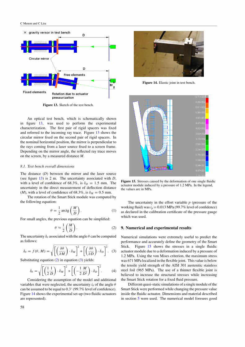
C Menon and C Lira
Figure 13 Sketch of the test bench
An optical test bench which is schematically shownin figure 13 was used to perform the experimentalcharacterization The first pair of rigid spacers was fixedand referred to the incoming ray trace Figure 13 shows thecircular mirror fixed on the second pair of rigid spacers Inthe nominal horizontal position the mirror is perpendicular tothe rays coming from a laser source fixed to a screen frameDepending on the mirror angle the reflected ray trace moveson the screen by a measured distance M
81 Test bench overall dimensions
The distance (D) between the mirror and the laser source(see figure 13) is 2 m The uncertainty associated with Dwith a level of confidence of 683 is δD = 15 mm Theuncertainty in the direct measurement of deflection distance(M) with a level of confidence of 683 is δM = 05 mm
The rotation of the Smart Stick module was computed bythe following equation
θ = 1
2arctg
(M
D
) (1)
For small angles the previous equation can be simplified
θ asymp 1
2
(M
D
) (2)
The uncertainty δθ associated with the angle θ can be computedas follows
δθ = f (θM) =radic[(
partθ
partM
)middot δM
]2
+
[(partθ
partD
)middot δD
]2
(3)
Substituting equation (2) in equation (3) yields
δθ =radic[(
1
2
1
D
)middot δM
]2
+
[(minus1
2
M
D2
)middot δD
]2
(4)
Considering the assumption of the model and additionalvariables that were neglected the uncertainty iθ of the angle θ
can be assumed to be equal to 03 (997 level of confidence)Figure 14 shows the experimental set-up (two fluidic actuatorsare represented)
Figure 14 Elastic joint in test bench
Figure 15 Stresses caused by the deformation of one single fluidicactuator module induced by a pressure of 12 MPa In the legendthe values are in MPa
The uncertainty in the effort variable p (pressure of theworking fluid) was ip = 0013 MPa (997 level of confidence)as declared in the calibration certificate of the pressure gaugewhich was used
9 Numerical and experimental results
Numerical simulations were extremely useful to predict theperformance and accurately define the geometry of the SmartStick Figure 15 shows the stresses in a single fluidicactuator module due to a deformation induced by a pressure of12 MPa Using the von Mises criterion the maximum stresswas 671 MPa localized in the flexible joint This value is belowthe tensile yield strength of the AISI 301 austenitic stainlesssteel foil (965 MPa) The use of a thinner flexible joint isbelieved to increase the structural stresses while increasingthe Smart Stick rotation for a fixed fluid pressure
Different quasi-static simulations of a single module of theSmart Stick were performed while changing the pressure valueinside the fluidic actuator Dimensions and material describedin section 5 were used The numerical model foresees good
58
A bio-inspired fluidic actuator for future space applications
0
1
2
3
4
0 02 04 06 08 1 12
Inner Pressure (MPa)
Ela
stic jo
int
rota
tio
n (
de
g)
Figure 16 Numerical prediction of one Smart Stick module withonly one fluidic actuator Red dots experimental results Blue linelinear fitting curve
1
2
3
5
4
0 02 04 06 08 1 12
Inner Pressure (MPa)
Ela
stic jo
int
rota
tio
n (
de
g)
Experimental dataBest fit
Figure 17 Experimental results of one Smart Stick module withonly one fluidic actuator Red line experimental results Blue linelinear fitting curve
performance of the system as presented in figure 16 Thisfigure shows that the rotation of a module is linearly changingwith the pressure inside the fluidic actuators (the red dotsrepresent single quasi-static numerical simulations the blueline is a fitting curve)
Several experimental tests were also performed using theSmart Stick prototype in order to characterize its behaviourFigure 17 shows that the rotation of the joint can beapproximated with a linear function (blue line) Figure 17concerns the use of one module of the Smart Stick havingonly one fluidic actuator embedded in the system Figure 18shows experimental results for eight cycles using the same jointmodule A fitting of the experimental data was performed inorder to obtain an empirical equation that could be used forcontrol purposes
θ = θ(p) = 357p + 013 (5)
where the angle is in degrees and the pressure in MPa Theuncertainty (997 level of confidence) associated with theslope of the function is plusmn013 MPandash1 and that associated withthe intercept is plusmn024
Figures 17 and 18 show the behaviour of the Smart Stickthat was correctly predicted by the numerical simulations(figure 16) Comparison of numerical end experimental testsproves both the correctness of the model and the quality of the
1
2
3
5
4
0 02 04 06 08 1 12
Inner Pressure (MPa)
Ela
stic jo
int
rota
tio
n (
de
g)
Uncertainty assess
plusmn 03
plusmn 0013
Single joint actuatorin the elastic joint
Figure 18 Multiple cycles of one Smart Stick module (only onefluidic actuator)
Figure 19 Stresses caused by the deformation of the Smart Stickinduced by a pressure of 12 MPa In the legend the values are inMPa
Figure 20 Strains caused by the deformation of the Smart Stickinduced by a pressure of 12 MPa In the legend the values are inpercentage
experimental set-up In addition figures 17 and 18 confirmthe high performance of the Smart Stick breadboard and showits potential for future applications
Numerical predictions of a complete Smart Stick werealso estimated by means of numerical simulations Stressesinduced on modules made of counteracting fluidic actuators areshown in figure 19 In this case the presence of the antagonistactuators reduces the bending stresses The maximum stresspick is still concentrated in the flexible joint and measures
59
C Menon and C Lira
0
1
2
0 02 04 06 08 1 12
Inner Pressure (MPa)
Ela
stic
join
t ro
tatio
n (
de
g)
Figure 21 Numerical prediction of one Smart Stick module withonly one fluidic actuator Blue dots experimental results Red linelinear fitting curve
0
1
2
02 04 06 08 1 12Inner Pressure (MPa)
Ela
stic
join
t ro
tatio
n (
de
g)
Pair of joint actuatorsin the elastic joint
Uncertainty assess
plusmn 03
plusmn 0013
Figure 22 Multiple cycles of one Smart Stick module (two fluidicactuators)
373 MPa Figure 20 shows that for the same pressure loadsthe maximum strain is reached by the compressed fluidicactuators The maximum value is about 4 which is in therange of deformations allowed by the material used for themicro-tubes (AKEMA Poly Block Ammide)
Quasi-static simulations of a single Smart Stick moduleequipped with opposing fluidic actuators were also performedand figure 21 shows the results The system still has a linear
Figure 23 Sketch of a closed fluid loop
behaviour which is guaranteed by the linear elasticity of theflexible joint Compared to the case shown in figure 16 thedeformation predicted by figure 21 is lower as an additionalforce is in this case required in order to compress the antagonistfluidic actuator
This predicted performance was validated byexperimental tests carried out considering a module ofthe Smart Stick equipped with two antagonistic fluidicactuators Figure 22 shows the experimental results ofeight pressurizationdepressurization cycles A fitting ofthe experimental data was performed in order to obtain anempirical equation that could be used for control purposes
θ = θ(p) = 149p + 004 (6)
where the angle is in degrees and the pressure in MPaThe uncertainty associated with the slope of the function isplusmn011 MPandash1 and uncertainty associated with the intercept isplusmn015
The consistency of the numerical prediction shown infigure 21 and the experimental results of figure 22 confirms thereliability of both the numerical model and the experimentalset-up
10 Future improvements and designs
In order to increase the performance of the Smart Stick acareful selection of the material employed is needed Theuse of aerogels and lighter and more flexible materials for thespacers is being considered Improvement in the design willfocus on multiple parallel mini-tubes which can bring moreflexibility to the system
The fundamental next step necessary to obtain a completemechatronic breadboard for space applications will be therealization of the multi-module Smart Stick incorporating aclosed fluid loop Figure 23 shows a sketch which presentsthe concept idea of two symmetric closed fluid loops in aspider inspired configuration In this figure the controllersends the commands to an actuator mechanism that squeezesan expandable reservoir The pressure of the working fluidwhich is confined inside a closed loop is thus increased Amicro-pipe links the reservoir to the Smart Stick which changes
60
A bio-inspired fluidic actuator for future space applications
its shape according to the pressure values The rotation ofthe flexible joint in which the Smart Stick is integrated ismeasured by embedded sensors that feed back the signal tothe controller
The use of a closed fluid loop which allows overcomingleakage and outgassing issues is considered to be a criticalpoint for a successful hydraulic space mechanism Futurework will be focused on the development of a completeclosed loop mechatronic system and particular attention willbe paid to the actuation system This could include smartmaterials such as piezoelectric materials shape memory alloysand electro-active polymers [17 24] In particular dielectricelectro-active polymers have promising characteristics for thisapplication as they exert considerable forces in a wide rangeof large deformations and can be space qualified Magneto-restrictive fluids will also be evaluated in order to improve thetorque performance of the system
11 Conclusions
A novel flexible joint with an embedded fluidic system ispresented in this paper The novel mechanism is inspired bythe joints and the hydraulic closed system of spiders Theproposed mechanism can be fabricated using traditional andinexpensive processes and methodologies The modularityof the mechanism can be used to design joints for largedisplacements The system was numerically simulated inorder to appropriately design the geometry and to predict itsquasi-static characteristics A miniaturized prototype was alsobuilt and tests were performed by using an optical test benchNumerical and experimental results are consistent and showthe feasibility of the design Improvements of the systemare also suggested and a closed fluid loop configuration isproposed for future investigations
Acknowledgments
The work was carried out thanks to NATO grant awarded toCristian Lira (grant no NATO-CNR 21536) The authorsalso thank Susanna Valpreda for her valuable support in thebibliographic review VICI AG International for providingcomponents of the screw actuated pump syringe Mario Vanninfor the characterization of the flexible metal foil and Devis andRomeo Facchin for their support in the manufacturing part
References
[1] Menon C and Lira C 2006 Spider-inspired embedded actuatorfor space applications AISBrsquo06mdashAdaptation in Artificialand Biological Systems (Bristol)
[2] Anderson J F and Prestwich K N 1975 The fluid pressurepumps of spiders (Chelicerata Araneae) Z Morphol Tiere81 257ndash77
[3] Bar-Cohen Y 2000 Electroactive polymers as artificialmusclesmdashcapabilities potentials and challenges Robotics2000 and Space 2000 (Albuquerque NM 28 Februaryndash2March)
[4] Barik M E 2000 Planetary Handbook (Cambridge CambridgeUniversity Press)
[5] Benaroya H Bernold L and Chua K M 2002 Engineeringdesign and construction of lunar bases J Aerospace Eng15 33ndash45
[6] Blickhan R and Barth F G 1985 Stains in the exoskeleton ofspiders J Comp Physiol 157 115ndash47
[7] Guffey C Townsend V R Jr and Felgenhauer B E 2000External morphology and ultrastructure of the prehensileregion of the legs of Leiobunum nigripes (ArachnidaOpiliones) J Arachnol 28 231ndash6
[8] Kitagawa A Tsukagoshi H and Segawa M 2000 Proposal of aconnective type active hose with many degrees of freedomfor the rescue operation 6th Triennial Int Symp on FluidControl Measurement and Visualization (SherbrookeCanada 2000)
[9] Jenkins C H M 2001 Gossamer spacecraft membrane andinflatable structures technology for space applicationsProg Astronaut Aeronaut 191 481ndash501
[10] Knight R and Nehmzow U 2002 Walking robots a survey anda research proposal Technical Report CSM-375 (Universityof Essex)
[11] Chou C P and Hannaford B 1994 Static and dynamiccharacteristics of McKibben pneumatic artificial musclesProc IEEE Int Conf on Robotics and Automation(San Diego CA May 1994)
[12] Lira C Angrilli F and Debei S 2002 Variable structure fabricand uses for it Patent Document WO02099172
[13] Manton S M 1958 Evolution of arthropodan locomotorymechanisms part 6 J Unn Soc (Zool) 43 488ndash556
[14] Manton S M 1958 Hydrostatic pressure and leg extension inarthropods Ann Mag Nat Hist (Series 13) 1 161ndash82
[15] Parry D A and Brown R H J 1959 The Hydraulic Mechanismof the Spider Leg (Department of Zoology University ofCambridge
[16] Parry D A and Brown R H J 1959 The jumping mechanism ofsalticid spiders J Exp Biol 36 654ndash64
[17] Rossi D Carpi F Jeronimidis G Gaudenzi P Tralli AZolesi V and Ayre M 2004 Electroactive Polymers forActuation and Sensing in Space Applications (IAC AIAAVancouver Canada)
[18] Sensenig A T and Shultz J W 2003 Mechanics of cuticularelastic energy storage in leg joints lacking extensor musclesin arachnids J Exp Biol 206 771ndash84
[19] Sensenig A T and Shultz J W 2004 Elastic energy storage inthe pedipalpal joints of scorpions and sun-spiders(Arachnida Scorpiones Solifugae) J Arachnol 32 1ndash10
[20] Schworer M Kohl M and Menz W 1998 Fluidic microjointsbased on spider legs Conf on New Actuators (Bremen)
[21] Shultz J W 1991 Evolution of locomotion in Arachnida thehydraulic pressure pump of the giant whipscorpionMastigoproctus giganteus (Uropygi) J Morphol210 13ndash31
[22] Stewart D M and Martin A W 1974 Blood pressure in thetarantula Dugesiella hentzi J Comp Physiol 88 141ndash72
[23] Wilson R S and Bullock J 1973 The hydraulic interactionbetween prosoma and opisthosoma in Amaurobius ferox(Chelicerata Araneae) Z Morphol Tiere 74 221ndash30
[24] Menon C Ayre M and Ellery A 2006 Biomimetics a newapproach for space systems design ESA Bull 125 20ndash6
61
- 1 Introduction
-
- 11 Inflatable systems
- 12 Hydraulic mechanisms
- 13 The challenging space environment
-
- 2 Leg extension system in spiders
- 3 Problem definition
- 4 Smart Stick
- 5 Prototype design
- 6 Fabrication
- 7 Smart Stick modelling
- 8 Experimental characterization and optical test bench
-
- 81 Test bench overall dimensions
-
- 9 Numerical and experimental results
- 10 Future improvements and designs
- 11 Conclusions
- Acknowledgments
- References
-

A bio-inspired fluidic actuator for future space applications
0
1
2
3
4
0 02 04 06 08 1 12
Inner Pressure (MPa)
Ela
stic jo
int
rota
tio
n (
de
g)
Figure 16 Numerical prediction of one Smart Stick module withonly one fluidic actuator Red dots experimental results Blue linelinear fitting curve
1
2
3
5
4
0 02 04 06 08 1 12
Inner Pressure (MPa)
Ela
stic jo
int
rota
tio
n (
de
g)
Experimental dataBest fit
Figure 17 Experimental results of one Smart Stick module withonly one fluidic actuator Red line experimental results Blue linelinear fitting curve
performance of the system as presented in figure 16 Thisfigure shows that the rotation of a module is linearly changingwith the pressure inside the fluidic actuators (the red dotsrepresent single quasi-static numerical simulations the blueline is a fitting curve)
Several experimental tests were also performed using theSmart Stick prototype in order to characterize its behaviourFigure 17 shows that the rotation of the joint can beapproximated with a linear function (blue line) Figure 17concerns the use of one module of the Smart Stick havingonly one fluidic actuator embedded in the system Figure 18shows experimental results for eight cycles using the same jointmodule A fitting of the experimental data was performed inorder to obtain an empirical equation that could be used forcontrol purposes
θ = θ(p) = 357p + 013 (5)
where the angle is in degrees and the pressure in MPa Theuncertainty (997 level of confidence) associated with theslope of the function is plusmn013 MPandash1 and that associated withthe intercept is plusmn024
Figures 17 and 18 show the behaviour of the Smart Stickthat was correctly predicted by the numerical simulations(figure 16) Comparison of numerical end experimental testsproves both the correctness of the model and the quality of the
1
2
3
5
4
0 02 04 06 08 1 12
Inner Pressure (MPa)
Ela
stic jo
int
rota
tio
n (
de
g)
Uncertainty assess
plusmn 03
plusmn 0013
Single joint actuatorin the elastic joint
Figure 18 Multiple cycles of one Smart Stick module (only onefluidic actuator)
Figure 19 Stresses caused by the deformation of the Smart Stickinduced by a pressure of 12 MPa In the legend the values are inMPa
Figure 20 Strains caused by the deformation of the Smart Stickinduced by a pressure of 12 MPa In the legend the values are inpercentage
experimental set-up In addition figures 17 and 18 confirmthe high performance of the Smart Stick breadboard and showits potential for future applications
Numerical predictions of a complete Smart Stick werealso estimated by means of numerical simulations Stressesinduced on modules made of counteracting fluidic actuators areshown in figure 19 In this case the presence of the antagonistactuators reduces the bending stresses The maximum stresspick is still concentrated in the flexible joint and measures
59
C Menon and C Lira
0
1
2
0 02 04 06 08 1 12
Inner Pressure (MPa)
Ela
stic
join
t ro
tatio
n (
de
g)
Figure 21 Numerical prediction of one Smart Stick module withonly one fluidic actuator Blue dots experimental results Red linelinear fitting curve
0
1
2
02 04 06 08 1 12Inner Pressure (MPa)
Ela
stic
join
t ro
tatio
n (
de
g)
Pair of joint actuatorsin the elastic joint
Uncertainty assess
plusmn 03
plusmn 0013
Figure 22 Multiple cycles of one Smart Stick module (two fluidicactuators)
373 MPa Figure 20 shows that for the same pressure loadsthe maximum strain is reached by the compressed fluidicactuators The maximum value is about 4 which is in therange of deformations allowed by the material used for themicro-tubes (AKEMA Poly Block Ammide)
Quasi-static simulations of a single Smart Stick moduleequipped with opposing fluidic actuators were also performedand figure 21 shows the results The system still has a linear
Figure 23 Sketch of a closed fluid loop
behaviour which is guaranteed by the linear elasticity of theflexible joint Compared to the case shown in figure 16 thedeformation predicted by figure 21 is lower as an additionalforce is in this case required in order to compress the antagonistfluidic actuator
This predicted performance was validated byexperimental tests carried out considering a module ofthe Smart Stick equipped with two antagonistic fluidicactuators Figure 22 shows the experimental results ofeight pressurizationdepressurization cycles A fitting ofthe experimental data was performed in order to obtain anempirical equation that could be used for control purposes
θ = θ(p) = 149p + 004 (6)
where the angle is in degrees and the pressure in MPaThe uncertainty associated with the slope of the function isplusmn011 MPandash1 and uncertainty associated with the intercept isplusmn015
The consistency of the numerical prediction shown infigure 21 and the experimental results of figure 22 confirms thereliability of both the numerical model and the experimentalset-up
10 Future improvements and designs
In order to increase the performance of the Smart Stick acareful selection of the material employed is needed Theuse of aerogels and lighter and more flexible materials for thespacers is being considered Improvement in the design willfocus on multiple parallel mini-tubes which can bring moreflexibility to the system
The fundamental next step necessary to obtain a completemechatronic breadboard for space applications will be therealization of the multi-module Smart Stick incorporating aclosed fluid loop Figure 23 shows a sketch which presentsthe concept idea of two symmetric closed fluid loops in aspider inspired configuration In this figure the controllersends the commands to an actuator mechanism that squeezesan expandable reservoir The pressure of the working fluidwhich is confined inside a closed loop is thus increased Amicro-pipe links the reservoir to the Smart Stick which changes
60
A bio-inspired fluidic actuator for future space applications
its shape according to the pressure values The rotation ofthe flexible joint in which the Smart Stick is integrated ismeasured by embedded sensors that feed back the signal tothe controller
The use of a closed fluid loop which allows overcomingleakage and outgassing issues is considered to be a criticalpoint for a successful hydraulic space mechanism Futurework will be focused on the development of a completeclosed loop mechatronic system and particular attention willbe paid to the actuation system This could include smartmaterials such as piezoelectric materials shape memory alloysand electro-active polymers [17 24] In particular dielectricelectro-active polymers have promising characteristics for thisapplication as they exert considerable forces in a wide rangeof large deformations and can be space qualified Magneto-restrictive fluids will also be evaluated in order to improve thetorque performance of the system
11 Conclusions
A novel flexible joint with an embedded fluidic system ispresented in this paper The novel mechanism is inspired bythe joints and the hydraulic closed system of spiders Theproposed mechanism can be fabricated using traditional andinexpensive processes and methodologies The modularityof the mechanism can be used to design joints for largedisplacements The system was numerically simulated inorder to appropriately design the geometry and to predict itsquasi-static characteristics A miniaturized prototype was alsobuilt and tests were performed by using an optical test benchNumerical and experimental results are consistent and showthe feasibility of the design Improvements of the systemare also suggested and a closed fluid loop configuration isproposed for future investigations
Acknowledgments
The work was carried out thanks to NATO grant awarded toCristian Lira (grant no NATO-CNR 21536) The authorsalso thank Susanna Valpreda for her valuable support in thebibliographic review VICI AG International for providingcomponents of the screw actuated pump syringe Mario Vanninfor the characterization of the flexible metal foil and Devis andRomeo Facchin for their support in the manufacturing part
References
[1] Menon C and Lira C 2006 Spider-inspired embedded actuatorfor space applications AISBrsquo06mdashAdaptation in Artificialand Biological Systems (Bristol)
[2] Anderson J F and Prestwich K N 1975 The fluid pressurepumps of spiders (Chelicerata Araneae) Z Morphol Tiere81 257ndash77
[3] Bar-Cohen Y 2000 Electroactive polymers as artificialmusclesmdashcapabilities potentials and challenges Robotics2000 and Space 2000 (Albuquerque NM 28 Februaryndash2March)
[4] Barik M E 2000 Planetary Handbook (Cambridge CambridgeUniversity Press)
[5] Benaroya H Bernold L and Chua K M 2002 Engineeringdesign and construction of lunar bases J Aerospace Eng15 33ndash45
[6] Blickhan R and Barth F G 1985 Stains in the exoskeleton ofspiders J Comp Physiol 157 115ndash47
[7] Guffey C Townsend V R Jr and Felgenhauer B E 2000External morphology and ultrastructure of the prehensileregion of the legs of Leiobunum nigripes (ArachnidaOpiliones) J Arachnol 28 231ndash6
[8] Kitagawa A Tsukagoshi H and Segawa M 2000 Proposal of aconnective type active hose with many degrees of freedomfor the rescue operation 6th Triennial Int Symp on FluidControl Measurement and Visualization (SherbrookeCanada 2000)
[9] Jenkins C H M 2001 Gossamer spacecraft membrane andinflatable structures technology for space applicationsProg Astronaut Aeronaut 191 481ndash501
[10] Knight R and Nehmzow U 2002 Walking robots a survey anda research proposal Technical Report CSM-375 (Universityof Essex)
[11] Chou C P and Hannaford B 1994 Static and dynamiccharacteristics of McKibben pneumatic artificial musclesProc IEEE Int Conf on Robotics and Automation(San Diego CA May 1994)
[12] Lira C Angrilli F and Debei S 2002 Variable structure fabricand uses for it Patent Document WO02099172
[13] Manton S M 1958 Evolution of arthropodan locomotorymechanisms part 6 J Unn Soc (Zool) 43 488ndash556
[14] Manton S M 1958 Hydrostatic pressure and leg extension inarthropods Ann Mag Nat Hist (Series 13) 1 161ndash82
[15] Parry D A and Brown R H J 1959 The Hydraulic Mechanismof the Spider Leg (Department of Zoology University ofCambridge
[16] Parry D A and Brown R H J 1959 The jumping mechanism ofsalticid spiders J Exp Biol 36 654ndash64
[17] Rossi D Carpi F Jeronimidis G Gaudenzi P Tralli AZolesi V and Ayre M 2004 Electroactive Polymers forActuation and Sensing in Space Applications (IAC AIAAVancouver Canada)
[18] Sensenig A T and Shultz J W 2003 Mechanics of cuticularelastic energy storage in leg joints lacking extensor musclesin arachnids J Exp Biol 206 771ndash84
[19] Sensenig A T and Shultz J W 2004 Elastic energy storage inthe pedipalpal joints of scorpions and sun-spiders(Arachnida Scorpiones Solifugae) J Arachnol 32 1ndash10
[20] Schworer M Kohl M and Menz W 1998 Fluidic microjointsbased on spider legs Conf on New Actuators (Bremen)
[21] Shultz J W 1991 Evolution of locomotion in Arachnida thehydraulic pressure pump of the giant whipscorpionMastigoproctus giganteus (Uropygi) J Morphol210 13ndash31
[22] Stewart D M and Martin A W 1974 Blood pressure in thetarantula Dugesiella hentzi J Comp Physiol 88 141ndash72
[23] Wilson R S and Bullock J 1973 The hydraulic interactionbetween prosoma and opisthosoma in Amaurobius ferox(Chelicerata Araneae) Z Morphol Tiere 74 221ndash30
[24] Menon C Ayre M and Ellery A 2006 Biomimetics a newapproach for space systems design ESA Bull 125 20ndash6
61
- 1 Introduction
-
- 11 Inflatable systems
- 12 Hydraulic mechanisms
- 13 The challenging space environment
-
- 2 Leg extension system in spiders
- 3 Problem definition
- 4 Smart Stick
- 5 Prototype design
- 6 Fabrication
- 7 Smart Stick modelling
- 8 Experimental characterization and optical test bench
-
- 81 Test bench overall dimensions
-
- 9 Numerical and experimental results
- 10 Future improvements and designs
- 11 Conclusions
- Acknowledgments
- References
-